technical report standard title page · pdf filetechnical report standard title page d....
TRANSCRIPT
TECHNICAL REPORT STANDARD TITLE PAGE D.
FHWA/TX-92/1219-1F 2. Government Accession No. 3. Recipient" Calala, No.
4. Tille and Subntle S. Repon Date
Two Post Driveable Sign Supports November 1991 6. Performing Organiza.ion Code
7. Author(s) 8. Performing Organizahon Repon No.
James R. Morgan and D. Lance Bullard, Jr. Report 1219-1F
9. Performing Organization Name and Address 10. Wort< Unit No.
Texas Transportation Institute The Texas A&M University System
11. Contract or Granl No. College Station, Texas 77843-3135
Study No. 2-5-91-1219 .
12. Sponsoring Ageru:y Name and Address 13. Type oC Report and Period Covered
Texas Department of Transportation Final - September 1990-P.O. Box 5051 August 1991 Austin, Texas 78763
14. Sponsoring Ageru:y Code
IS. Supplementary Notes
Research performed in cooperation of the U.S. Department of Transportation and Federal Highway Administration. Research Study Title: Two Post Driveable Sign Supports
16. Abs.ract
Small sign supports and installations represent a major and ongoing investment by the Texas Department of Transportation. The development of a generic system could result in substantial savings without sacrificing safety. To this end, during the period of 10/21/1987 - 8/31/1989, the Texas Department of Transportation and the Texas Transportation Institute conducted research project 2-18-88-1122. A single post system was developed and tested as a part of the project. In addition, a driveable anchor was developed and tested for tubular sign supports. The anchor successfully met all current federal impact performance criteria for single post installations in either strong or weak soils (NCHRP Report 230 classification SI and S2, respectively). Also, the anchor installation proved to be fully reusable following impact by a test vehicle. The anchor is easily driven and was designed to minimize field maintenance problems (such as leaning posts). While this anchor system has received good reviews, the two-post version with current 2-3/8 inch diameter steel tube sign posts fails to meet federal impact performance criteria for low impact speeds.
The concept of developing a successful generic dual post sign support system was extended under this study. Successful development and implementation of such a system would permit the vast majority of all small sign installations to be treated as a single system. This will result in substantial savings in acquisition, replacement and inventory costs.
18. Distribution Statement 17. Key Words
No restrictions. This document is available to the public sign supports, driveable, safety through the National Technical Information Service. 5285 Port Royal Road Springfield, Virginia 22161
19. Securily Classif. (of Ibis report) 20. Securily Class if. (or .his page) 21. No. of Pages 22. Price
Unclassified Unclassified 96
Form DOT F 1700.7 (8-69)

TWO POST DRIVEABLE SIGN SUPPORTS
Study No. 2-5-91-1219
Prepared by: James R. Morgan
D. Lance Bullard, Jr.
Prepared for: Texas Department of Transportation
Austin, Texas
TEXAS TRANSPORTATION INSTITUTE TEXAS A&M UNIVERSITY SYSTEM COLLEGE STATION, TEXAS 77843
August 1991

METRIC (SI*) CONVERSION FACTORS
APPROXIMATE CONVERSIONS TO SI UNITS APPROXIMATE CONVERSIONS TO SI UNITS lymboI When You Know Multiply By To F1ncf BrmboI Symbol WIMn You Know Multiply 8, To F1ncf S,mbol
LENGTH LENGTH .. 5 ... .. In Inches centimetres · E " mm mllllmetres 0.039 Inches In
2.54 em =-- ... 3.28 feel ft
It = m metres feet 0.3048 metres m
iiii.- - metres 1.09 yards yd · .. m yd yards 0.914 metres m = ml miles 1.81 kilometres km ft km kilometres 0.621 miles ml - ~
- = !: AREA · -
AREA .. - = = - mm' mlllimetres squared 0.0016 square Inches In'
'n' square Inches 645.2 c::entImetressquared cm' ~ e: m' metres squared 10.761 square feet ftl
ftl square feet 0.0929 metres squared m' = km' kilometres squared 0.39 square miles ml' · =--ydl square yards 0.836 metres squared m' .. - ha hectores (10000 m*) 2.53 acres ac
mil square miles 2.59 kilometres squared km' :! - -
ac acres 0.395 hectares ha - = !! MASS (weight) · : ... - ~ g grams 0.0353 ounces Ol
MASS (weight) - ~ ~ kg kilograms 2.205 pounds Ib -- = - Mg megagrams (1 000 kg) 1.103 short tons T Ol ounces 28.35 grams g -Ib pounds 0.454 kilograms kg -- VOLUME T short ton. (2000 Ib) 0.907 megagrams Mg -
mL mlllllltres 0.034 fluid ounces II Ol · l IItres 0.264 gallons gal
VOLUME -- m' metres cubed 35.315 cubic feet ft· --- m' metres cubed 1.308 cubic yards yd' fI 0% fluid ounc.s 21.57 mlllllltres mL -gal gallons 3.785 IItres L -ft, cubic feet 0.0328 metres cubed m' TEMPERATURE (exact) -ydl CObic yard. 0.0765 metre. cubed ml
- OC Celsius 9/5 (then Fahrenheit OF NOTE: Volumes greater than 1000 l shall be shown In mi. - temperature add 32) temperature -
- Of - Of 3Z a, 212
TEMPERATURE (exact) II - -f' , I ! I • ~ <t;O I ' , ~ , l,1~, I ,1?O, , ,~J ! - _ ~ i _ io i 0 io i 40 • eo ' ~ • 100
OF Fahrenheit 519 (after Celsius oc ~ u ~
temperature subtracting 32) temperature These factors conform to the requirement of FHWA Order 5190.1A .
• SI Is the symbol for the International System of Measurements

DISCLAIMER
This document is disseminated under the sponsorship of the Texas Department of
Transportation in the interest of information exchange. The Texas Department of
Transportation assumes no liability for its contents or use thereof. The contents of this
report reflect the views of the authors who are solely responsible for the opinions, fmdings,
and conclusions presented herein. The report does not necessarily reflect the official views
or policies of the Texas Department of Transportation. This report does not constitute a
standard, specification, or regulation.
The Texas Department of Transportation does not endorse products or manufacturers.
Trade or manufacturers' names may appear herein only because they are considered essential
to the object of this document.
11

PREFACE
Small sign supports and installations represent a major and ongoing investment by the
Texas Department of Transportation. The development of a generic system could result in
substantial savings without sacrificing safety. To this end, during the period of tO/2111987 -
8/3111989, the Texas Department of Transportation and the Texas Transportation Institute
conducted research project 2-18-88-1122. A single post system was developed and tested as
a part of the project. In addition, a driveable anchor was developed and tested for tubular
sign supports. The anchor successfully met all current federal impact perfonnance criteria
for single post installations in either strong or weak soils (NCHRP Report 230 classification
Sl and S2, respectively). Also, the anchor installation proved to be fully reusable following
impact by a test vehicle. The anchor is easily driven and was designed to minimize field
maintenance problems (such as leaning posts). While this anchor system has received good
reviews, the two-post version with current 2-3/8 inch diameter steel tube sign posts fails to
meet federal impact perfonnance criteria for low impact speeds.
The concept of developing a successful generic dual post sign support system was
extended under this study. Successful development and implementation of such a system
would permit the vast majority of all small sign installations to be treated as a single system.
This will result in substantial savings in acquisition, replacement and inventory costs.
iii

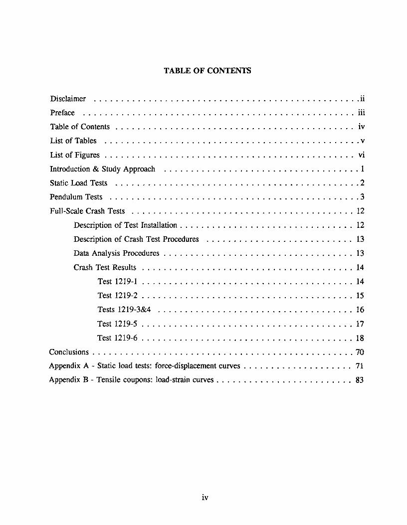
TABLE OF CONTENTS
Disclaimer .................................................11 Preface .................................................. iii
Table of Contents .... . . . . . . . . . . . . . . . . . . . . . . . . . . . . • . . . . . . . . . . . iv
List of Tables ............................................... v
List of Figures . . . . . . . . . . . . . . . . . . . . . . . . . . . . . . . . . . . . . . . . . . . . . . VI
Introduction & Study Approach .................................... 1
Static Load Tests ............................................. 2
Pendulum Tests .............................................. 3
Full-Scale Crash Tests ......................................... 12
Description of Test Installation. . . . . . . . . . . . . . . . . . . . . . . . . . . . . . . . 12
Description of Crash Test Procedures ........................... 13
Data Analysis Procedures . . . . . . . . . . . . . . . . . . . . . . . . . . . . . . . . . . . 13
Crash Test Results .. . . . . . . . . . . . . . . . . . . . . . . . . . . . . . . . . . . . . . 14
Test 1219-1 ....................................... 14
Test 1219-2 ....................................... 15
Tests 1219-3&4 .................................... 16
Test 1219-5 ....................................... 17
Test 1219-6 ....................................... 18
Conclusions . . . . . . . . . . . . . . . . . . . . . . . . . . . . . . . . . . . . . . . . . . . . . . . . 70
Appendix A - Static load tests: force-displacement curves . . . . . . . . . . . . • . . . . . . . 71
Appendix B - Tensile coupons: load-strain curves . . . . . . . . . . . . . . . . . . . . . . . . . 83
iv


LIST OF TABLES
Table Title ~
1. Performance Evaluation Summary - Pendulum Tests . . . . . . . . . . . . . . . 4
v

Fi~ure
1.
2.
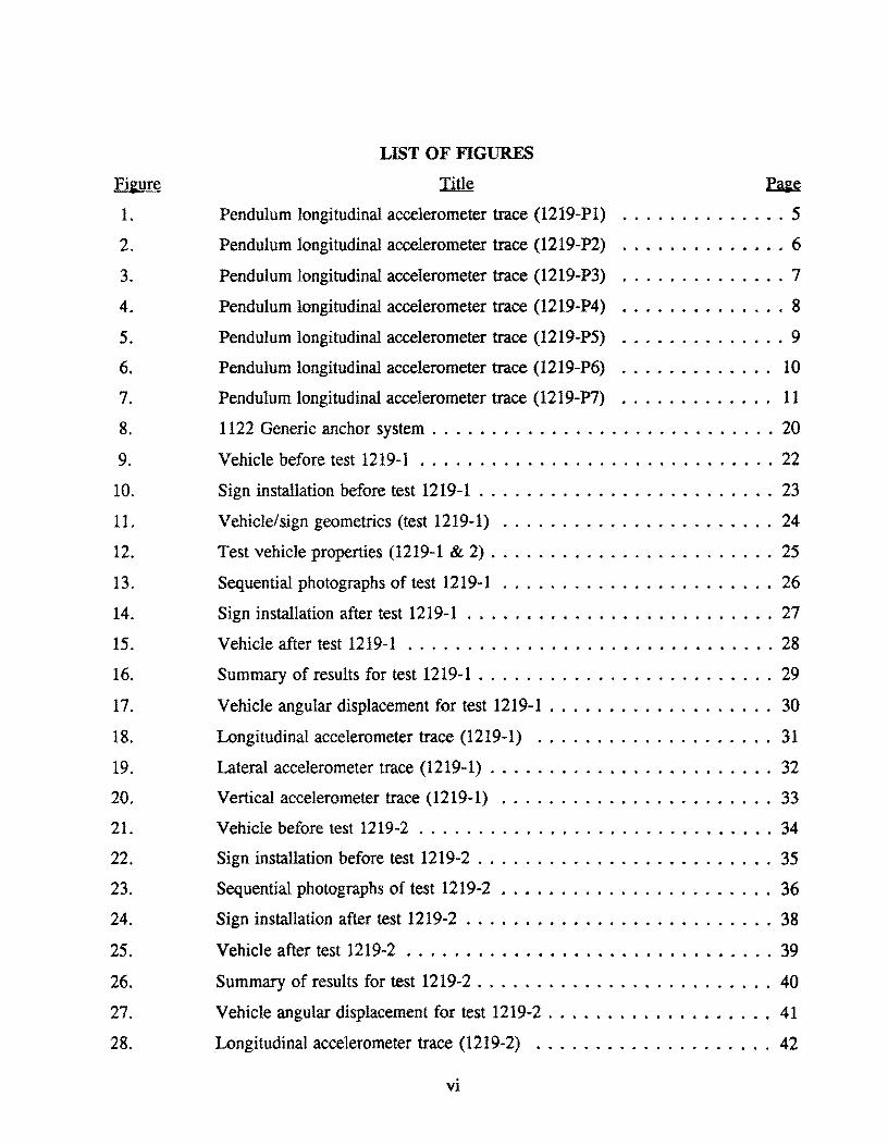
LIST OF FIGURES
Title ~
Pendulum longitudinal accelerometer trace (1219-Pl) .............. 5
Pendulum longitudinal accelerometer trace (1219-P2) .............. 6
3. Pendulum longitudinal accelerometer trace (1219-P3) .............. 7
4. Pendulum longitudinal accelerometer trace (1219-P4) .............. 8
5. Pendulum longitudinal accelerometer trace (1219-P5) .............. 9
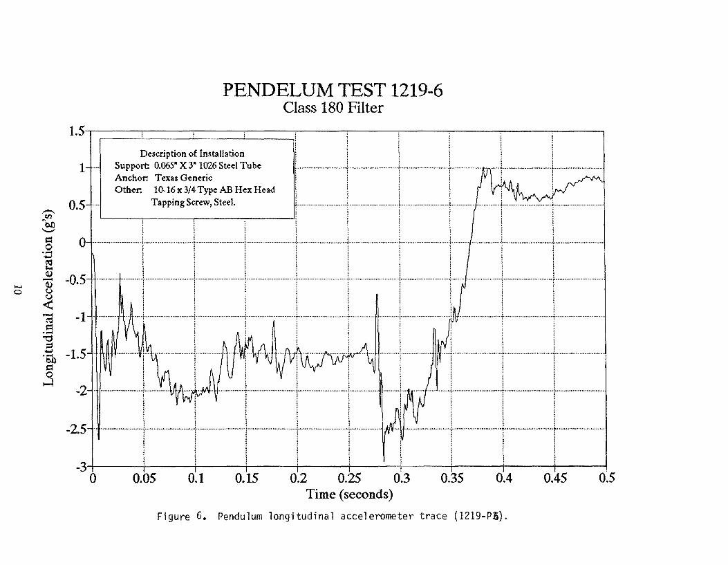
6. Pendulum longitudinal accelerometer trace (1219-P6) ............. 10
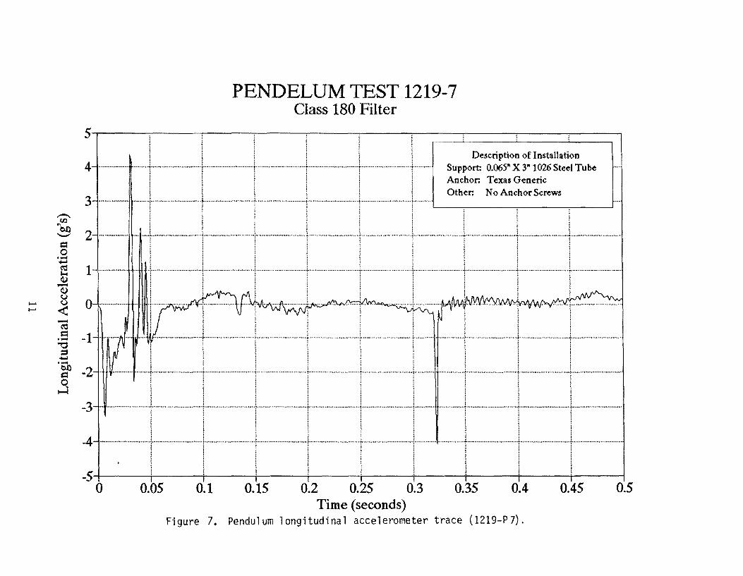
7. Pendulum longitudinal accelerometer trace (1219-P7) ............. 11
8. 1122 Generic anchor system . . . . . . . . . . . . . . . . . . . . . . . . . . . . . 20
9. Vehicle before test 1219-1 .............................. 22
10. Sign installation before test 1219-1 ......................... 23
11. Vehicle/sign geometries (test 1219-1) ....................... 24
12. Test vehicle properties (1219-1 & 2) ........................ 25
13. Sequential photographs of test 1219-1 ....................... 26
14. Sign installation after test 1219-1 .......................... 27
15. Vehicle after test 1219-1 ............................... 28
16. Summary of results for test 1219-1 ......................... 29
17. Vehicle angular displacement for test 1219-1 ................... 30
18. Longitudinal accelerometer trace (1219-1) .................... 31
19. Lateral accelerometer trace (1219-1) ........................ 32
20. Vertical accelerometer trace (1219-1) ....................... 33
21. Vehicle before test 1219-2 .............................. 34
22. Sign installation before test 1219-2 . . . . . . . . . . . . . . . . . . . . . . . . . 35
23. Sequential photographs of test 1219-2 . . . . . . . . . . . . . . . . . . . . . . . 36
24. Sign installation after test 1219-2 .......................... 38
25. Vehicle after test 1219-2 . . . . . . . . . . . . . . • . . . . . . . . . . . . . . . . 39
26. Summary of results for test 1219-2 ......................... 40
27. Vehicle angular displacement for test 1219-2 ................... 41
28. Longitudinal accelerometer trace (1219-2) .................... 42
VI

Fi~ure
29.
30.
31.
32.
33.
34.
35.
36.
37.
38.
39.
40.
41.
42.
43.
44.
45.
46.
47.
48.
49.
50.
51.
52.
53.
LIST OF FIGURES (continued)
Title Pa~e
Lateral accelerometer trace (1219-2) ........................ 43
Vertical accelerometer trace (1219-2) ....................... 44
Vehicle before test 1219-5 ...........•.................. 45
Sign installation before test 1219-5 . . . . . . . . . . . . . . . . . . . . . . . . . 46
Vehicle/sign geometries (test 1219-5) ....................... 47
Test vehicle properties (1219-5) .......................... 48
Sequential photographs of test 1219-5 . . . . . . . . . . . . . . . . . . . . . . . 49
Sign installation after test 1219-5 . . . . . . . . . . . . . . . . . . . . . . . . . . 51
Vehicle after test 1219-5 ............................... 52
Summary of results for test 1219-5 ......................... 53
Vehicle angular displacement for test 1219-5 . . . . . . . . . . . . . . . . . . . 54
Longitudinal accelerometer trace (1219-5) .................... 55
Lateral accelerometer trace (1219-5) ............ : ........... 56
Vertical accelerometer trace (1219-5) ....................... 57
Vehicle before test 1219-6 .............................. 58
Sign installation before test 1219-6 ......................... 59
Vehicle/sign geometries (test 1219-6) ....................... 60
Test vehicle properties (1219-6) .......................... 61
Sequential photographs of test 1219-6 . . . . . . . . . . . . . . . . . . . . . . . 62
Sign installation after test 1219-6 .......................... 64
Vehicle after test 1219-6 ............................... 65
Summary of results for test 1219-6 ......................... 66
Vehicle angular displacement for test 1219-6 ................... 67
Longitudinal accelerometer trace (1219-6) .................... 68
Lateral accelerometer trace (1219-6) ........................ 69
vii

INTRODUCTION & STUDY APPROACH
The Texas Department of Transportation (TxDOT) contracted with the Texas
Transportation Institution (TTl) to develop, crash test, and evaluate the performance of a
generic two post driveable sign support system. The scope of this project included an
examination of suitability of the generic driveable sign support anchor developed under a
previous project (#1122), the adaptability of this anchor to different post materials and the
crash testing of generic dual post sign systems.
The primary objective of the study was to determine if a generic driveable dual post
sign support system can satisfy safety impact criteria. The following two modifications were
made to the current steel post system in an effort to meet the project objectives:
1. Increase the diameter of the sign support to 3 inches (thereby
decreasing required wall thickness of the steel sign post and allowing
easier collapsing of the tube during impact), and
2. study alternative [to the set screw used in the 1122 design] attachment
details between the post and the anchor (possibly allowing easier
pullout of the sign post from the anchor under impact conditions while
still providing vandal resistance).
Increasing the sign post diameter to 3 in and altering the attachment mechanism also allows
for wider availability of alternative materials such as aluminum or fiber reinforced plastic
with adequate bending capacity to support wind loads. These substitutions may afford
superior impact performance but also should increase competition thereby reducing overall
cost of the system.
In addition, static and pendulum tests were performed during the development phase
of this project to 1) study the pull out characteristics of the various post-to-anchor attachment
systems, 2) verify wind load performance and 3) to study the performance of the modified
breakaway systems under low speed impacts.
The final phase of this project was full-scale vehicle crash testing. The crash tests
performed allowed for accessment of the actual safety performance of the appurtenance in
both strong and weak soils (NCHRP Report 230 classification SI and S2, respectively).
1

STATIC WAD TESTS
Static load tests were conducted using a small sign support test apparatus developed at
TIL Each static load test was conducted on a single support that was securely held vertical
and fixed against rotation while applying a horizontal concentrated load at a distance of 9 ft
(2.7 m) above the theoretical ground surface. Loading was perpendicular to the plane of the
post and applied continuously by means of a actuated hydraulic cylinder. The applied load
was measured using a load cell, also mounted 9 ft (2.7 m) above the ground surface. In
addition, sign post angle of rotation was measured near the theoretical ground surface. The
effective load and angle of rotation were electronically recorded. Loading of the post
specimen continued until a buckling failure occurred. The maximum load recorded prior to
failure defined the capacity of the support. Load versus displacement graphs for each
configuration tested are shown in Appendix A. For the purposes of this study, acceptable
supports were those which provide at least as much static bending capacity as the 2-3/8 in
steel Poz-Loc system currently used by TxDOT. The following supports and configurations
were found to be acceptable:
Poz-Loc (0.095 in x 2-3/8 in steel tube)
HwyCom (0.25 in x 3 in FRP tube)
0.065 in x 3 in 1026 Steel Tube - with or w/o champher
0.065 in x 3 in 1026 Steel Tube - with or w/o styrene sleeve
2
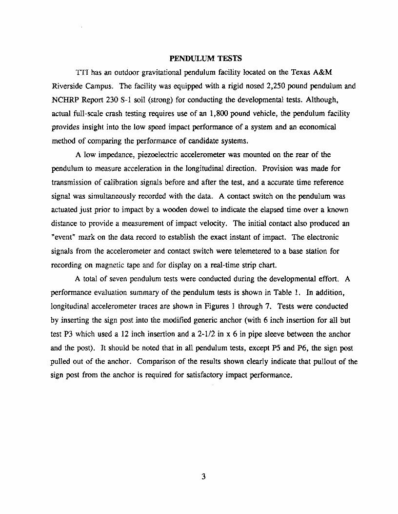
PENDULUM TESTS
TTl has an outdoor gravitational pendulum facility located on the Texas A&M
Riverside Campus. The facility was equipped with a rigid nosed 2,250 pound pendulum and
NCHRP Report 230 8-1 soil (strong) for conducting the developmental tests. Although,
actual full-scale crash testing requires use of an 1,800 pound vehicle, the pendulum facility
provides insight into the low speed impact performance of a system and an economical
method of comparing the performance of candidate systems.
A low impedance, piezoelectric accelerometer was mounted on the rear of the
pendulum to measure acceleration in the longitudinal direction. Provision was made for
transmission of calibration signals before and after the test, and a accurate time reference
signal was simultaneously recorded with the data. A contact switch on the pendulum was
actuated just prior to impact by a wooden dowel to indicate the elapsed time over a known
distance to provide a measurement of impact velocity. The initial contact also produced an
"event" mark on the data record to establish the exact instant of impact. The electronic
signals from the accelerometer and contact switch were telemetered to a base station for
recording on magnetic tape and for display on a real-time strip chart.
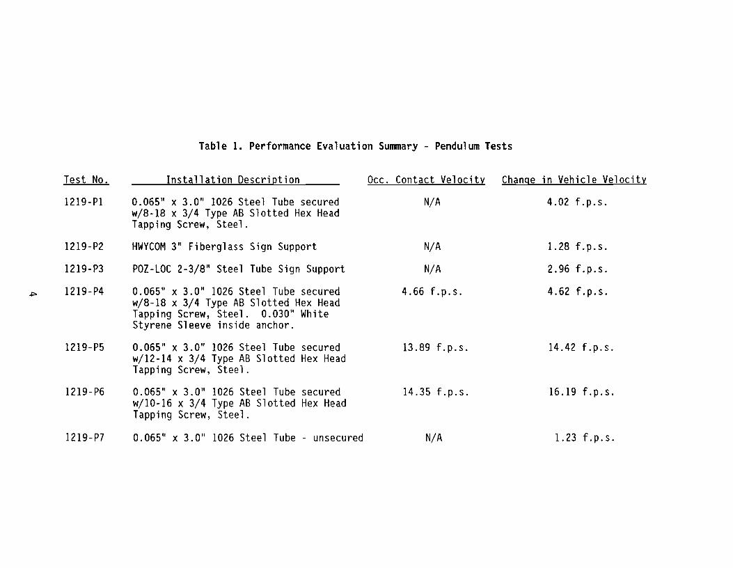
A total of seven pendulum tests were conducted during the developmental effort. A
performance evaluation summary of the pendulum tests is shown in Table 1. In addition,
longitudinal accelerometer traces are shown in Figures 1 through 7. Tests were conducted
by inserting the sign post into the modified generic anchor (with 6 inch insertion for all but
test P3 which used a 12 inch insertion and a 2-112 in x 6 in pipe sleeve between the anchor
and the post). It should be noted that in all pendulum tests, except P5 and P6, the sign post
pulled out of the anchor. Comparison of the results shown clearly indicate that pullout of the
sign post from the anchor is required for satisfactory impact performance.
3
Test No.
1219-Pl
1219-P2
1219-P3
1219-P4
1219-P5
1219-P6
1219-P7
Table 1. Performance Evaluation Summary - Pendulum Tests
Installation Description Occ. Contact Velocity Change in Vehicle Velocity
0.065" x 3.0" 1026 Steel Tube secured N/A 4.02 f.p.s. w/8-18 x 3/4 Type AB Slotted Hex Head Tapping Screw, Steel.
HWYCOM 3" Fiberglass Sign Support N/A 1.28 f.p.s.
POI-LOC 2-3/8" Steel Tube Sign Support N/A 2.96 f.p.s.
0.065" x 3.0" 1026 Steel Tube secured 4.66 f.p.s. 4.62 f.p.s. w/8-18 x 3/4 Type AB Slotted Hex Head Tapping Screw, Steel. 0.030" White Styrene Sleeve inside anchor.
0.065" x 3.0" 1026 Steel Tube secured 13.89 f.p.s. 14.42 f.p.s. w/12-14 x 3/4 Type AB Slotted Hex Head Tapping Screw, Steel.
0.065" x 3.0" 1026 Steel Tube secured 14.35 f.p.s. 16.19 f.p.s. w/l0-16 x 3/4 Type AB Slotted Hex Head Tapping Screw, Steel.
0.065" x 3.0" 1026 Steel Tube - unsecured N/A 1.23 f.p.s.

PENDELUM TEST 1219-1 Class 180 Filter
1~----~------~----~----~------~----~------~----~------~----~ l
I o 5 ,uU"~''''''''~.'''''.h •• ~ ••• i ...... ······· .... «·u •• u···i.···· •.•.•.•.•••••.• H ....... ·i_ ...... d ••••••• u ••••••••• ~ ..•••••••••••••••••••••••••• .i ........ h ....... u •••••• · •.• i .... u ...................... > .......................... hJ •••••••••••••••.••••••••.•• { ••• u ••• u ••••••••••••••.
• iii iii iii :! :;::: i : 1 :::::! i 1 ; iii I ~
~ 0-._--1- ...... _-1....--1.+-1 .. L ................ ! )1. ..... . .. "OJ) : i
i -0.5· ·························1·························· ·1····························1···························1····························+··························+··························t····························f···························l··············· .. . ..... ::: i : ; : : : ..... i 1 ill i 1 i 1 fl l! i ! 1 iii 1
..2 -1, . . . ..... .... ·1· ...... . ... ·· .. j····························I····················· ...... ~ ........................... ~ .................... ·······I···························~·················· ......... f. .......................... J.............. . ...... .
] I I I I ! I I I ] -1.5' .. ··········t··························(·························l·············· .. ··········j····························t····· .. ···················t·········· .. ·············1···························t·················· ......... 1""............ . ...... . -11""4 ! j 1 1 l i ~ ! ~ ~ i! i 1 i i 1 i i
::::I ! iii 1 i 1 i i ..... 2 l , l , : : , , , ........ _. • ............... _. __ •• ~ ••••••• _._ ............... h.~ ••• __ ••••••• _ ••••••••••••••• : ••••••• _ •• _ •••••••••••••••• ~ •• n •••• n ••• _._.uu ••••••• -:- •••••••• H ••••••••• _ •••• _ .. _~ ___ ._u ••••••••••• u •• _ •••• ":' ••• n ••••• _ ••••••••••••• H.~ •••• u ••••••••••• u ........ -:-............. __ •••••••
OJ) ~! ~ ! f ~ ~ l
.3 -2.5 ...... __ ......... / .......... -I._ ....... _ ..... j. ... __ .... ....... (._......_( ................ _ .. j ~Ption 0: In,tallation i
-3 . ··-I·-··I·-·~l-l--·I ~~~ :~~ i:~!:~e:e::e:d I 1 ! ! ! I Tapping Screw, Steel
~ ~ ~ 1 ! ~ -3.5-+----+----+----+----+----+-----;-----+----;------+-----1 o 0.05 0.1 0.15 0.2 0.25 0.3 0.35 0.4 0.45 0.5
Time (seconds) Figure 1. Pendulum longitudinal accelerometer trace (1219-Pl).
PENDELUM TEST 1219-2 Class 180 Filter
0.2~----~----~----~----~----~~----~----~----~----~----~
l
:; -0.2- -····t-I·ll· : ; : . . , . . . . 2 -0.4' ......... ········"j-··························l·················· ........ , ........................... j-................. ·········t··························-j-··························-[···························t···························t···························
I -0.6-1-·I-I---·I---I--l-~---j---I·--< iii i ~ j j j j
] -0.8 ····I·II----++--IL--j----I· "0 iii i : l i i = 1 iii iii , i i .~ -" ········ .. ···········T·· .. ··· .. ··· .... · .... ·····T··· .. ········ .. · .. ·· .. ····T .. ···· .... ········· .. · .. ··Y' .. ··· .. ··· .......... · .... ·y ...... · .. · .... · ........ ·· .. r ........ · .. · ........ · .... r··· .. · .. · .. ···· .... · ...... r ........ · ................. Y' ......................... .
~ j i j j ~ ~ ! ! i
,3 -1.2" ··········-·······r············I---·············1-_·····t······ .. ·--+-I Suppo~es;~i~~7:~n~~tion -1.4 .......... · .. ·· .......... 1 .. ··········· .. · ............ 1 .. · .. · .. ··· ...... · .......... [ .. · .............. · .. · .. ····t .............. · .... ···· .... t ...... · .... ·· ...... ········j ~:::;.r. z;:: ~:~~~: AB Hex Head
I ! ! ill Tapping Screw, Steel i ~ ~ ! l l : ! ! : : :~----~----~----------~
16~-----+:------+:------~:----~:~----~:------~:------~-----r----~r---~ - . ... o 0.05 0.1 0.15 0.2 0.25 0.3 0.35 0.4 0.45 0.5
Time (seconds)
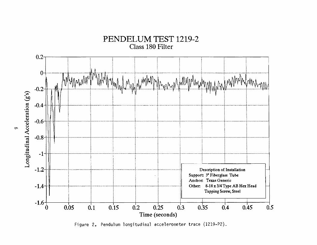
Figure 2. Pendulum longitudinal accelerometer trace (1219-P2).
PENDELUM TEST 1219-3 Class 180 Filter
0.5~----~i----~----~------~----~----~----~----~----~--~
O-r --- ------------------------1-( .. ~AA,---+---1: .... ~ .... 1+1'I
05 . . : . . . . . _.. .. .. u ..... nu.~._.~ .. ~~"' .. _~-_ .. _- ........ uu .....•. !."._ ... H._ ...................... ~..... .-.-•••• --•••• - ... -~ ........................ - ••• i .... --...................... !_u __ .. d .................. + .............. _ ..... H __ •••• ~ ................ n~" ... u_
1il' i j j j j j j j
~ , I I I I I i I d -1" ....... Uu • • ••• , ............. h.u •• uni.n .... u •••••••••••••••••••• , ••• u .......................... ~ •••••••••••••• _.u .. __ •••••• ~ ..................... u •••• ·i ................. U •• h._ .... ~~U.h ............... • •••• _4 ••••. _ •••••• u ............. ~ ........ H •••••••• _.0 ....... .
. g II!!! 1 ! ! ! E i 1 ! iii i ! 1 (j) iii iii i i 1
I -l~:--'-':I-~~-'~-'I--~-'I~]::I=-I--l::-'::::::I::-~-:-'-I:~=~-' ~ ~ l i ~ 1 ~ ~ ! ! = ::::::::: .~ -2.5" ; ; ; ; ; ; : : 1
! -3 ___=-.~[~:-~:-.:I-.~-_-.]I~r~:__J~~:~~~~~~}I~.~lI:~~~r--I I I i I I Support 2-3/8" Pos-Loe Tube
-3.5 .. ·· .. ··· ...... ···········1·········· .. ·"···,,,,,,,,,·1,, ...... ·,,,, .. ·,···"··,···I···················"" .... t .... ,·,,,,,,,··,, .. ,,·, .. ··t·········· .. · .. ···· .. ······1 ~:::;,r: ~~:~ ~:~: AB Hex Head I I I i I I Tapping Screw, Steel
l ~ ~ i 1 ~ _4~-----+------+------r----~r-----~----~------+------+------r-----~
o 0.05 0.1 0.15 0.2 0.25 0.3 0.35 0.4 0.45 0.5 Time (seconds)
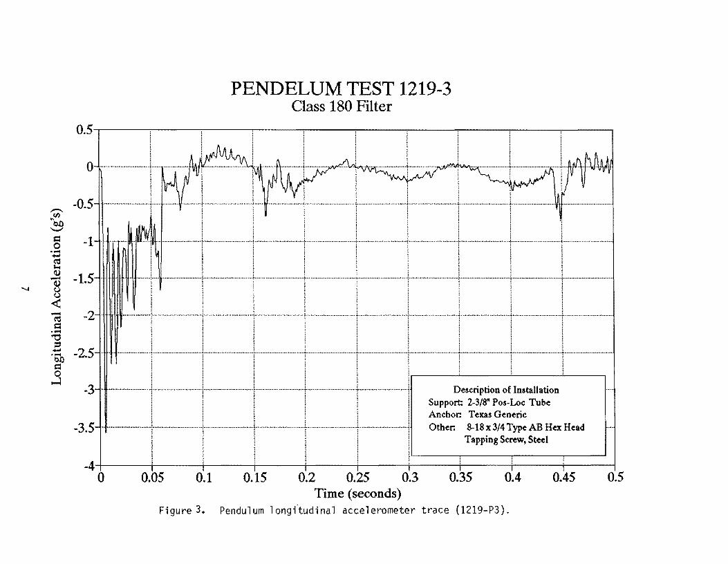
Figure 3. Pendul um 1 ongftudi na 1 accelerometer trace (1219-P3).

co
PENDELUM TEST 1219-4 Class 180 Filter
1.------r-----,1----~------~----~----~----~------~----~----~
O.S········T--1- 1· t·II·····j-1-...-r--
i .O.:-.::::-.:.L::.~~I··-:r:·:l:::::_:t·~::~:l~J...·~-.: ..... .... ~ (I) -~ <
-1
c; -1.5···· .. ······· .. ···iUH ...•. HHU.
I = ..... "'0 S ..... co = j
-2.5 Description of Installation
Support: 0.065" X 3" 1026 Steel Tube Anchor: Texas Generic Other: 8-18x 3/4 Type AB Hex Head
Tapping Screw, Steel. 0.030" White Styrene Friction Surface
·3.5-t-J---+---+-----i----+---+---i----+----i---+-----l o 0.05 0.1 0.15 0.2 0.25 0.3 0.35 0.4 0.45 0.5
Time (seconds) Figure 4. Pendulum longitudinal accelerometer trace (1219-P4).
-.. ",Vl. QO
---d o • .;:3
~ Q) .......
PENDELUM TEST 1219-5 Class 180 Filter
2~----~------~----~----~~----~----~------~----~------~----~
15 . . . . . . . . . • ~u •••......• ".~.~ ........ ! ....................... ~.u.~.~ •........... u~ .........•... ! ......................... -.. U:~H .. U.H .........•.. -.. u_1H~ .. -....•......•.......... ! ......... --............ u~.1· ................. unu •.. 1 ......... U .....•....•••••• t'U.hU.H ............... .
1..I ... _IJ.1J.IJL.L.
~ W < -0.5 ............... .
~ .9 -1, ............... ... . ........................... , .......................... , ........................... , ............................ , ............................ , ............................ ,.......... . ......... + ........................... , ........................... .
I .1.5 .. ... ~ ...... ... 1..... . ..... i .... . .. j ..... I.. .1. ... .:... ...... 1 .. -.-1 j I!: 'I I
-2 .................... ·1· .. · .... ·· .. ·· .. · ..... ! ........... ·······+ .... ·· .... ····· .. ··· .... ··1 ...... · .... · .. ····· ...... ··+ .......... ·· ............. +.... Description of Installation
-25···· ·f··················t-················I·············I···_·······[···········_··1 ~::.~ i~~:72fu;,~::~d -34-----~-----+------~----+-----~-----+~---.------~----.-----~
o 0.05 0.1 0.15 0.2 0.25 0.3 0.35 0.4 0.45 0.5 Time (seconds)
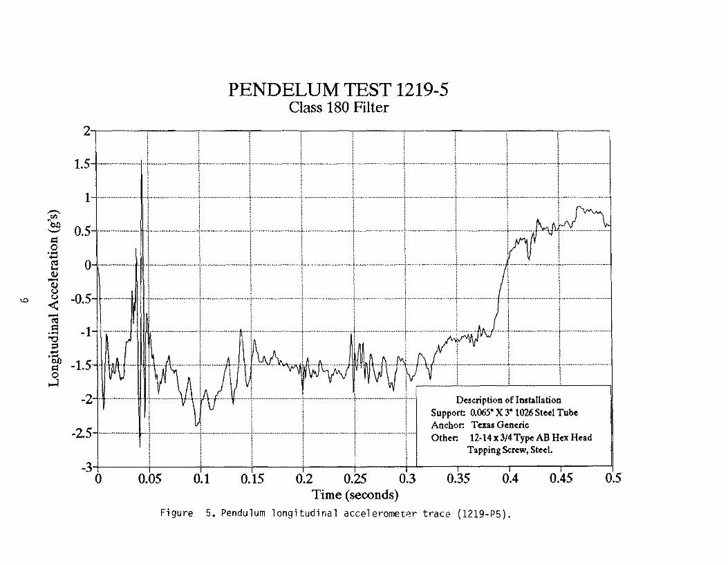
Figure 5. Pendulum longitudinal acceleromet~r trace (1219-P5).
,-. rn ~b£)
'-'
= 0 '.::1 e <I) -....... <I)
0 u
< -~ = ,~
"'0 e '6h = 0
.....:l
PENDELUM TEST 1219-6 Class 180 Filter
1,5~----~----~----~----~----~------~----~----~----~----~
Description of Installation \ Support: 0.065" X 3" 1026 Steel Tube : ............................ , ............................ j ............................ ; ....................... .;. •.•.•••.••••••••••••••••••• <. •..•.••••••••..............
Anchor: Texas Generic ! I i I I ! 1
0,5 .... Other: ~~:~:g3~:r::,~~.HexHead 1 ........................... 1-........................... j .......................... ..\. ......................... r ........................... : ........................... .
~--~------~----~----~! ! i I ! I ! : l : : :
-0.5
-1 . : : : :: ::
I ! I I! I! -1.5
~: ::: i i
~ -3;------;------~-----;------~----~------~T-------~----~------~----~
o 0.05 0.1 0.15 0.2 0.25 0.3 0.35 0.4 0.45 0.5 Time (seconds)
Figure 6. Pendulum longitudinal accelerometer trace (1219-Pi).
,-. "tn on '-" Cl 0 ...... +-I
S (1) -(1) ()
...... () ...... -< -~ = .-
~ := +-I .-on = 0
.....:l
PENDELUM TEST 1219-7 Class 180 Filter
5.-----,-----,-----~----~----~----~--~~--~~--~----~
1 ~ 4 ..... ~ ....... u .. u .u···~··i············· .. · .. u .. uu···i··~··uuu ............ ~.·~·i·······.H.U ..... ___ ....... .t. ..• H ....... ~.-u ....... ~.-.c····················· .. ·····t···UH .. H
3 -...J .. -I-J...-J-----l-..l
1 .............. .
o I I i
-1
-3
Description of Installation Support: 0.065" X 3" 1026 Steel Tube Anchor: Texas Generic Other: No Anchor Screws
L-__ ~ ____ ~ ______ ~ __ ~
-5~----~-----+----~~----+-----4-----~-----+------~----+-----~ o 0.05 0.1 0.15 0.2 0.25 0.3 0.35 0.4 0.45 0.5
Time (seconds) Figure 7. Pendulum longitudinal accelerometer trace (1219-P7).

FULL-SCALE CRASH TESTS
The objective of these tests were to determine the impact characteristics of dual
support sign installations when attached to Texas Generic Sign Anchors and placed in
NCHRP Report 230 "strong soil". These tests were conducted using an 1,800 lb vehicle
travelling at 20 and 60.0 mi/h. Standards established in AASHTO "Standard Specifications
for Structural Supports for Highway Signs, Luminaires, and Traffic Signals" and NCHRP
Report 230 were used for analyses and evaluation of these tests.
DESCRIPTION OF TEST INSTALLATION
The sign installations used in the full-scale crash tests consisted of a 5/8 in X 4 ft X 7
ft-3 in plywood sign blank mounted to two - 0.065 in x 3 in x 138 in 1026 DOM steel tube
supports. Each support was placed into a Texas Generic Sign Anchor driven into either
NCHRP Report 230 S-1 or S-2 (strong and weak, respectively) soil. The bottom of sign
mounting height was 7 ft-O in.
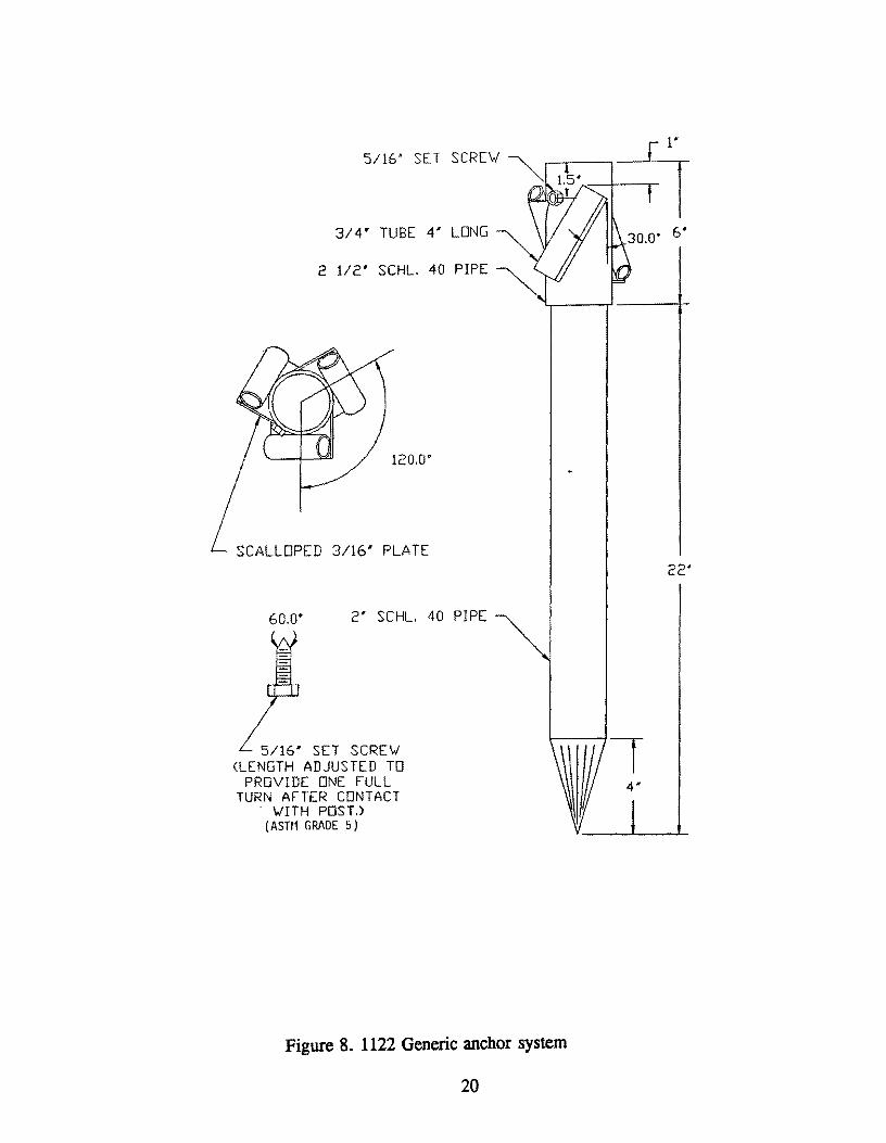
The Texas Generic Driveable Sign Anchor was developed at Texas Transportation
Institute (TTl) in cooperation with the Texas Department of Transportation (TxDOT) under a
previously conducted research project (Study No. 2-18-88-1122). Details of the 1122 anchor
system are shown in Figure 8. The body of the 1122 anchor is constructed from 2 in
schedule 40 steel pipe, 22 in. in length. Attached to the top of the 2 in pipe, by welding, is
a 2-112 in x 6 in schedule 40 section of pipe. The 2-1/2 in pipe is used as the sign support
anchoring sleeve. The 1122 anchor was modified for this project by shortening the bottom 2
in section to 16 in and adding a 3 in x 6 in schedule 40 section of pipe to the top to serve as
the anchoring sleeve for a 3 in diameter sign post. This modification allows the anchor to
accept either a 3 in post (with a 6 in insertion) or a 2-3/8 in post (with a 12 in insertion).
The anchor is designed to be manually driven into the ground and cross anchored using three
- #6 (314 in diameter x 36 in), grade 60 steel, concrete reinforcing bars. The cross anchors
are guided and attached through 3/4 in X 4 in steel tubes welded to the outer circumference
of the 2-1/2 in pipe at 120 degree intervals using 3/16 in scalloped steel plates. In addition,
the steel cross anchor tubes are rotated 30 degrees off of the anchors vertical axis. The
overall length of the anchor assembly is 28 in.
12

The sign posts are placed six inches into the 3 in pipe sleeve and in tests 1219-1,2 &
5 are secured by means of two 8-18 x 3/4 Type AB slotted hex head steel tapping screws per
post. In test 1219-6 the sign post is placed six inches into the 3 in pipe sleeve but is
unsecured.
DESCRIPTION OF CRASH TEST PROCEDURES
The crash test procedures were in accordance with guidelines presented in NCHRP
Report 230. The test vehicle was instrumented with three rate transducers to measure roll,
pitch, and yaw rates and a triaxial accelerometer near the vehicle center of gravity to
measure acceleration levels.
The electronic signals from the accelerometers and transducers were telemetered to a
base station for recording on magnetic tape and for display on a real-time strip chart.
Provision was made for transmission of calibration signals before and after the test, and
accurate time reference signal was simultaneously recorded with the data. Contact switches
on the bumper were actuated just prior to impact by wooden dowels to indicate the elapsed
time over a known distance to provide a measurement of impact velocity. The initial contact
also produced an "event" mark on the data record to establish the exact instant of impact.
In accordance with NCHRP Report 230, an unrestrained, uninstrumented special
purpose 50th percentile anthropomorphic test dummy was positioned in the front seat of the
test vehicle. This dummy was used to evaluate typical unsymmetrical vehicle mass
distribution and its effect on vehicle stability during impact.
Photographic coverage of the tests included two high-speed cameras, one perpendicular
to the sign installation and the other located downstream 45 degrees from the point of
impact. The films from these cameras were used to observe phenomena occurring during
collision and to obtain time-event, displacement and angular data. A 3/4-inch video-camera
and 35 mm still cameras were also used for documentary purposes.
DATA ANALYSIS PROCEDURES
The analog data from the accelerometers and transducers were digitized, using a
microcomputer, for analysis and evaluation of performance. The digitized data were then
13
analyzed using two computer programs: DIGITIZE and PLOTANGLE. Brief descriptions
on the functions of these two computer programs are provided as follows.
The DIGITIZE program uses digitized data from vehicle-mounted linear
accelerometers to compute occupant/compartment impact velocities, time of
occupant/compartment impact after vehicle impact, and the highest O.OIO-second average
ridedown acceleration. The DIGmZE program also calculates vehicle impact velocity and
the change in vehicle velocity at the end of a given impulse period. In addition, maximum
average accelerations over 0.050-second intervals in each of three directions are computed.
Acceleration versus time curves for the longitudinal, lateral, and vertical directions are then
plotted from the digitized data of the vehicle-mounted linear accelerometers using
commercially available software (Quattro Pro 3.0).
The PLOT ANGLE program uses the digitized data from the yaw, pitch, and roll rate
transducers to compute angular displacement in degrees at approximately O.OOI-second
intervals and then instructs a plotter to draw a reproducible plot: yaw, pitch, and roll versus
time. These displacements are in reference to the vehicle-fixed coordinate system with the
initial position and orientation of the vehicle-fixed coordinate system being that which existed
at initial impact.
CRASH TEST RESULTS
Test 1219-1
A 1986 Chevrolet Sprint (shown in Figure 9) impacted the sign installation (Figures
10 and 11) at 19.9 miles per hour (32.0 kIn/h) using a cable reverse tow and guidance
system. Test inertia mass of the vehicle was 1,800 Ib (817 kg) and its gross static mass was
1,9701b (894 kg). The height from roadway surface to the lower edge of the vehicle
bumper was 15.8 inches (40.0 cm) and 21.0 inches (53.3 cm) to the top of the bumper.
Other dimensions and information on the vehicle are given in Figure 12.
The vehicle was free wheeling and unrestrained just prior to impact. The point of
impact was the centerline of the sign installation with the centerline of the vehicle. Upon
impact, the sign supports began to yield at bumper height and ground level. By
14
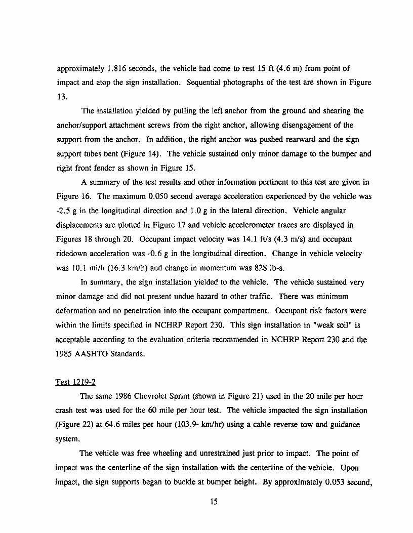
approximately 1.816 seconds, the vehicle had come to rest 15 ft (4.6 m) from point of
impact and atop the sign installation. Sequential photographs of the test are shown in Figure
13.
The installation yielded by pulling the left anchor from the ground and shearing the
anchor/support attachment screws from the right anchor, allowing disengagement of the
support from the anchor. In addition, the right anchor was pushed rearward and the sign
support tubes bent (Figure 14). The vehicle sustained only minor damage to the bumper and
right front fender as shown in Figure 15.
A summary of the test results and other information pertinent to this test are given in
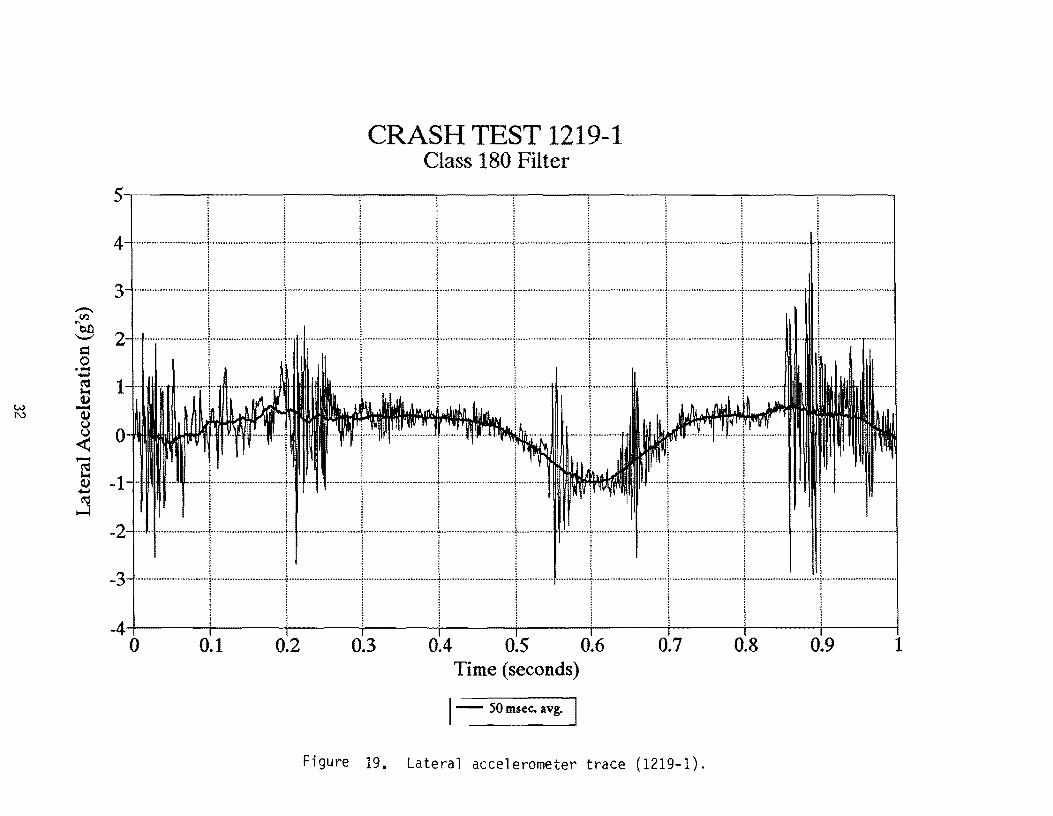
Figure 16. The maximum 0.050 second average acceleration experienced by the vehicle was
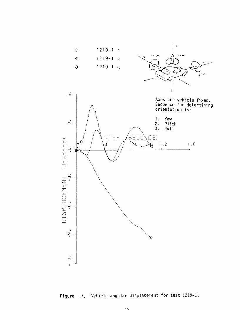
-2.5 g in the longitudinal direction and 1.0 g in the lateral direction. Vehicle angular
displacements are plotted in Figure 17 and vehicle accelerometer traces are displayed in
Figures 18 through 20. Occupant impact velocity was 14.1 ftls (4.3 mls) and occupant
ridedown acceleration was -0.6 g in the longitudinal direction. Change in vehicle velocity
was 10.1 mi/h (16.3 lan/h) and change in momentum was 828 lb-s.
In summary, the sign installation yielded to the vehicle. The vehicle sustained very
minor damage and did not present undue hazard to other traffic. There was minimum
deformation and no penetration into the occupant compartment. Occupant risk factors were
within the limits specified in NCHRP Report 230. This sign installation in "weak soil" is
acceptable according to the evaluation criteria recommended in NCHRP Report 230 and the
1985 AASHTO Standards.
Test 1219-2
The same 1986 Chevrolet Sprint (shown in Figure 21) used in the 20 mile per hour
crash test was used for the 60 mile per hour test. The vehicle impacted the sign installation
(Figure 22) at 64.6 miles per hour (103.9- kmlhr) using a cable reverse tow and guidance
system.
The vehicle was free wheeling and unrestrained just prior to impact. The point of
impact was the centerline of the sign installation with the centerline of the vehicle. Upon
impact, the sign supports began to buckle at bumper height. By approximately 0.053 second,
15
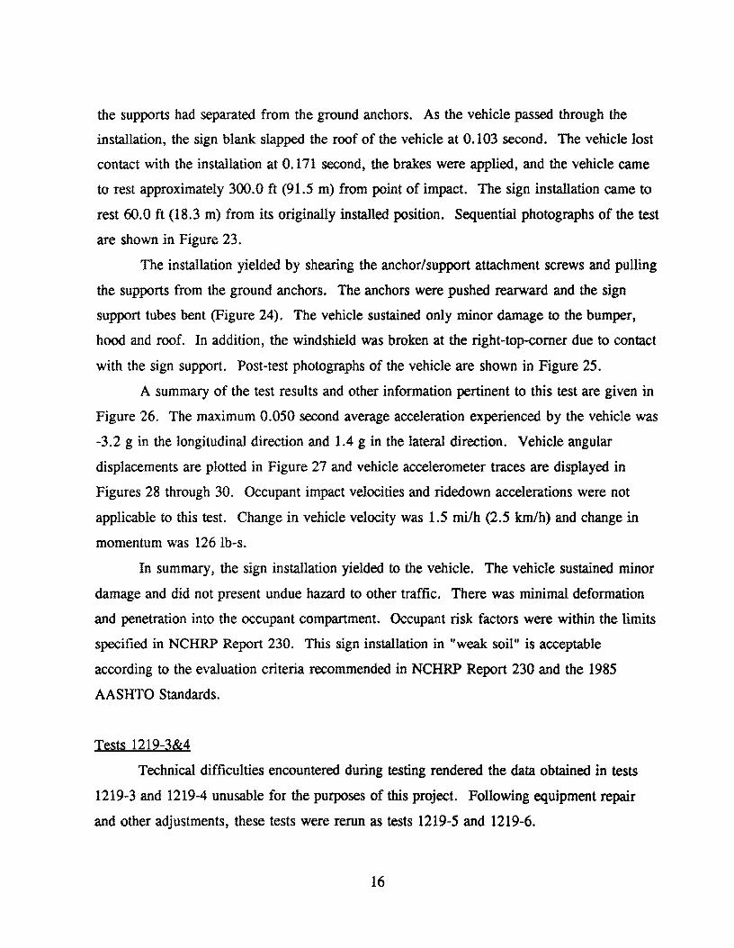
the supports had separated from the ground anchors. As the vehicle passed through the
installation, the sign blank slapped the roof of the vehicle at 0.103 second. The vehicle lost
contact with the installation at 0.171 second, the brakes were applied, and the vehicle came
to rest approximately 300.0 ft (91.5 m) from point of impact. The sign installation came to
rest 60.0 ft (18.3 m) from its originally installed position. Sequential photographs of the test
are shown in Figure 23.
The installation yielded by shearing the anchor/support attachment screws and pulling
the supports from the ground anchors. The anchors were pushed rearward and the sign
support tubes bent (Figure 24). The vehicle sustained only minor damage to the bumper,
hood and roof. In addition, the windshield was broken at the right-top-comer due to contact
with the sign support. Post-test photographs of the vehicle are shown in Figure 25.
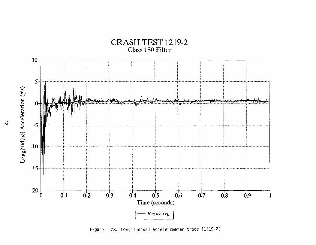
A summary of the test results and other information pertinent to this test are given in
Figure 26. The maximum 0.050 second average acceleration experienced by the vehicle was
-3.2 g in the longitudinal direction and 1.4 g in the lateral direction. Vehicle angular
displacements are plotted in Figure 27 and vehicle accelerometer traces are displayed in
Figures 28 through 30. Occupant impact velocities and ridedown accelerations were not
applicable to this test. Change in vehicle velocity was 1.5 milh (2.5 km/h) and change in
momentum was 126 lb-s.
In summary, the sign installation yielded to the vehicle. The vehicle sustained minor
damage and did not present undue hazard to other traffic. There was minimal deformation
and penetration into the occupant compartment. Occupant risk factors were within the limits
specified in NCHRP Report 230. This sign installation in "weak soil" is acceptable
according to the evaluation criteria recommended in NCHRP Report 230 and the 1985
AASHTO Standards.
Tests 1219-3&4
Technical difficulties encountered during testing rendered the data obtained in tests
1219-3 and 1219-4 unusable for the purposes of this project. Following equipment repair
and other adjustments, these tests were rerun as tests 1219-5 and 1219-6.
16
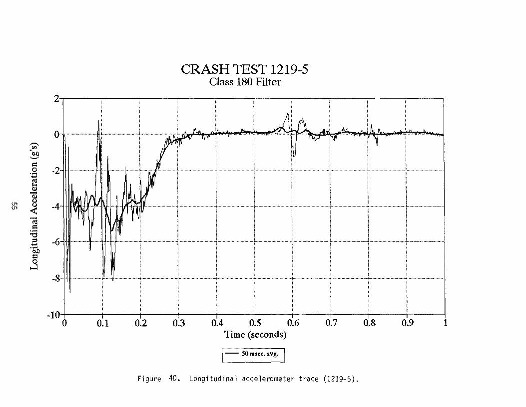
Test 1219-5
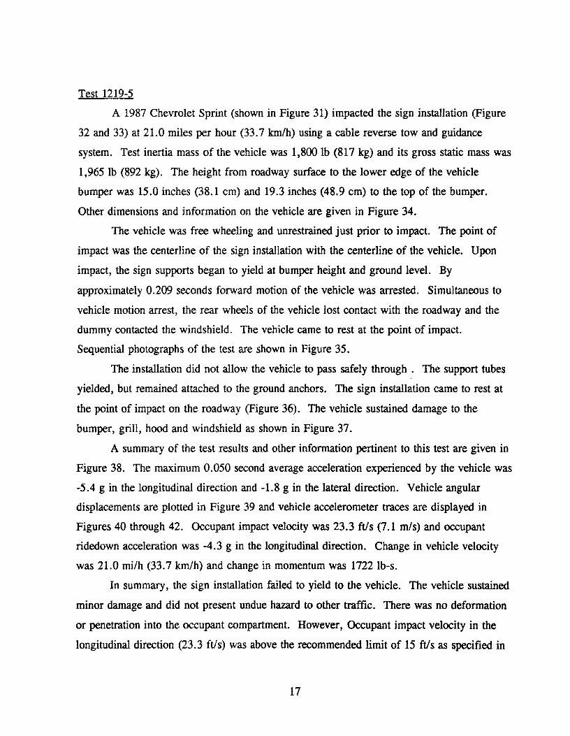
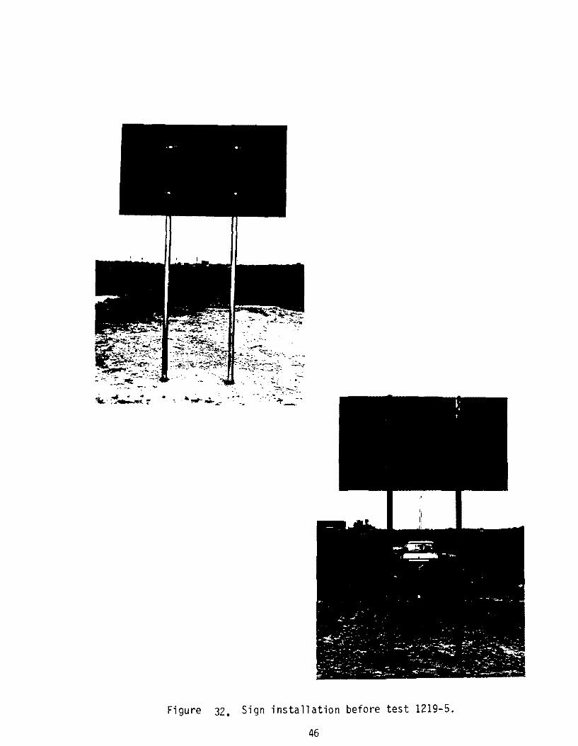
A 1987 Chevrolet Sprint (shown in Figure 31) impacted the sign installation (Figure
32 and 33) at 21.0 miles per hour (33.7 lan/h) using a cable reverse tow and guidance
system. Test inertia mass of the vehicle was 1,800 lb (817 kg) and its gross static mass was
1,965 Ib (892 kg). The height from roadway surface to the lower edge of the vehicle
bumper was 15.0 inches (38.1 cm) and 19.3 inches (48.9 cm) to the top of the bumper.
Other dimensions and information on the vehicle are given in Figure 34.
The vehicle was free wheeling and unrestrained just prior to impact. The point of
impact was the centerline of the sign installation with the centerline of the vehicle. Upon
impact, the sign supports began to yield at bumper height and ground level. By
approximately 0.209 seconds forward motion of the vehicle was arrested. Simultaneous to
vehicle motion arrest, the rear wheels of the vehicle lost contact with the roadway and the
dummy contacted the windshield. The vehicle came to rest at the point of impact.
Sequential photographs of the test are shown in Figure 35.
The installation did not allow the vehicle to pass safely through. The support tubes
yielded, but remained attached to the ground anchors. The sign installation came to rest at
the point of impact on the roadway (Figure 36). The vehicle sustained damage to the
bumper, grill, hood and windshield as shown in Figure 37.
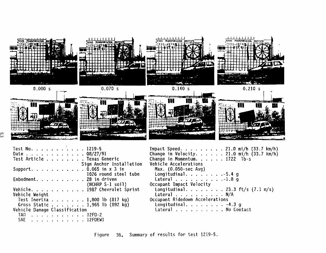
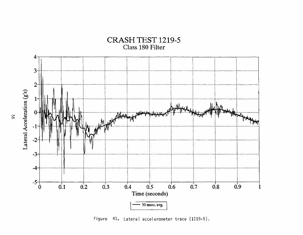
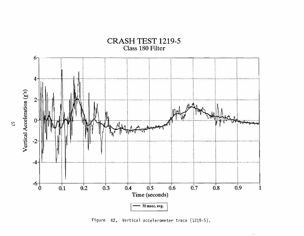
A summary of the test results and other information pertinent to this test are given in
Figure 38. The maximum 0.050 second average acceleration experienced by the vehicle was
-5.4 g in the longitudinal direction and -1.8 g in the lateral direction. Vehicle angular
displacements are plotted in Figure 39 and vehicle accelerometer traces are displayed in
Figures 40 through 42. Occupant impact velocity was 23.3 fils (7.1 m/s) and occupant
ridedown acceleration was -4.3 g in the longitudinal direction. Change in vehicle velocity
was 21.0 milh (33.7 lan/h) and change in momentum was 1722 lb-s.
In summary, the sign installation failed to yield to the vehicle. The vehicle sustained
minor damage and did not present undue hazard to other traffic. There was no deformation
or penetration into the occupant compartment. However, Occupant impact velocity in the
longitudinal direction (23.3 ftls) was above the recommended limit of 15 ftls as specified in
17

NCHRP 230. This sign installation in "strong soil" is not acceptable according to the
evaluation criteria recommended in NCHRP Report 230 and the AASHTO Standards.
Test 1219-6
A 1986 Yugo (shown in Figure 43) impacted the sign installation (Figures 44 and 45)
at 19.8 miles per hour (31.9 km/h) using a cable reverse tow and guidance system. Test
inertia mass of the vehicle was 1,800 lb (817 kg) and its gross static mass was 1,965 Ib (892
kg). The height from roadway surface to the lower edge of the vehicle bumper was 13.0
inches (33.0 cm) and 18.3 inches (46.4 cm) to the top of the bumper. Other dimensions and
information on the vehicle are given in Figure 46.
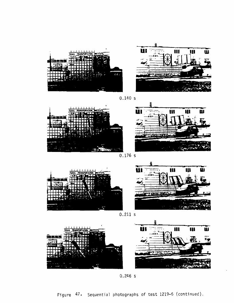
The vehicle was free wheeling and unrestrained just prior to impact. The point of
impact was the centerline of the sign installation with the centerline of the vehicle. Upon
impact, the sign supports began to yield at bumper height and ground level. By
approximately 0.208 seconds forward motion of the vehicle was arrested. Simultaneous to
vehicle motion arrest, the rear wheels of the vehicle lost contact with the roadway and the
dummy contacted the windshield. The vehicle came to rest at the point of impact.
Sequential photographs of the test are shown in Figure 47.
The installation did not allow the vehicle to pass safely through. The support tubes
yielded, but remained attached to the ground anchors. The sign installation came to rest at
the point of impact on the roadway (Figure 48). The vehicle sustained damage to the
bumper, grill, hood and right front strut shown in Figure 49.
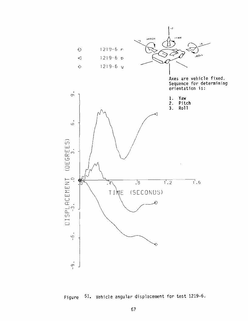
A summary of the test results and other information pertinent to this test are given in
Figure 50. The maximum 0.050 second average acceleration experienced by the vehicle was
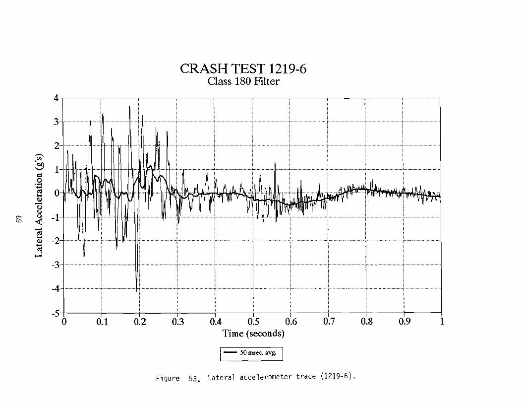
-4.6 g in the longitudinal direction and 1.1 g in the lateral direction. Vehicle angular
displacements are plotted in Figure 51 and vehicle accelerometer traces are displayed in
Figures 52 through 54. Occupant impact velocity was 22.3 ft/s (6.8 m/s) and occupant
ridedown acceleration was -5.4 g in the longitudinal direction. Change in vehicle velocity
was 19.8 mi/h (31.9 km/h) and change in momentum was 1623 lb-s.
In summary, the sign installation failed to yield to the vehicle. The vehicle sustained
minor damage and did not present undue hazard to other traffic. There was no deformation
18
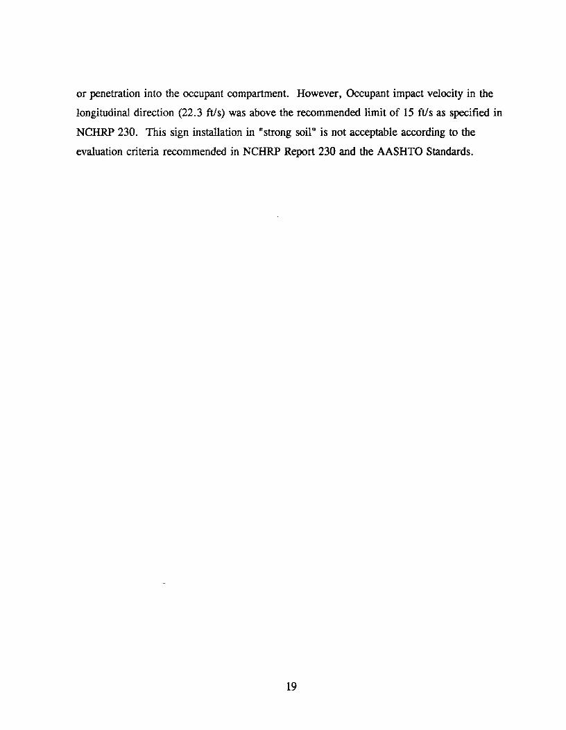
or penetration into the occupant compartment. However, Occupant impact velocity in the
longitudinal direction (22.3 fils) was above the recommended limit of 15 ftls as specified in
NCHRP 230. This sign installation in "strong soil" is not acceptable according to the
evaluation criteria recommended in NCHRP Report 230 and the AASHTO Standards.
19
3/4* TUBE 4' LONG
2 112* SCHL, 40 PIPE
120,0'
SCALLOPED 3/16' PLATE
60,0· 2' SCHL, 40 PIPE
5/16' SET SCREV (LENGTH ADJUSTED TO
PROVIDE ONE FULL TURN AFTER CONTACT
. VITH POST,) (ASm GRADE 5)
Figure 8. 1122 Generic anchor system
20
22'
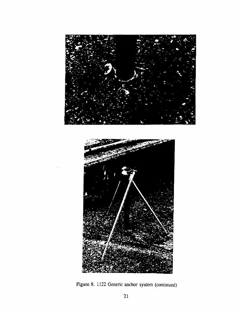
Figure 8. 1122 Generic anchor system (continued)
21

Figure 9. Vehicle before test 1219-1.
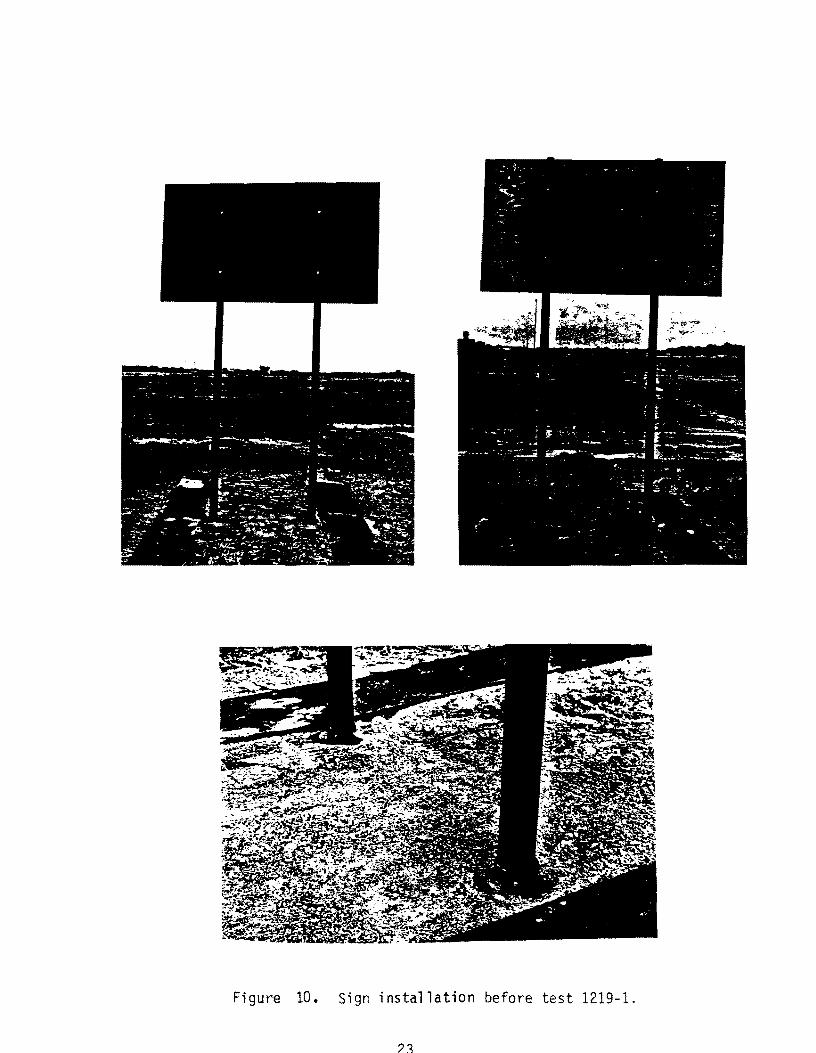
Figure 10. Sign installation before test 1219-1.
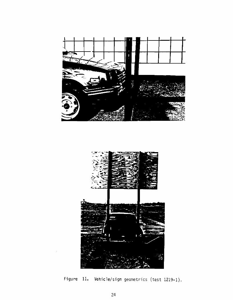
Figure 11. Vehicle/sign geometries (test 1219-1),
24

Date: 08/22/91 Test No. : 12i9-1 and 2 VIN: JGlMR0857GK725285
Make: Chevrolet Mode 1: Spri nt Yea r: -=1~9-",-8",,-6 __ _ Odome ter: --1...] 5 ....... 5LL2~1 __ _
Bias Ply: Tire Size: P145 80 R12 Ply Rating: ----- Be lted: Rad i a 1 :
f -r---t
l
a p
~
Ti re d i a----+~r4>-l ~yheel dia----+t+J1II-I
s
j
m 0
b
4-wheel weight for c.g. det. if 582
Mass - pounds Curb
Ml 477 /931/454
M2 283/568/285
MT 1499
Note any damage to vehicle
rf
Accelerometers
~311 T
101 11
Accelerometers
k
c
f
500 ir 365 rr 353
Test Inertial Gross Static
1082 1165
718 805
1800 1970
prior to test:
*d = overall height of vehicle
Tire Condition: good _
Height of. fair rear accelerometer badly worn __ 29~1I
9
Vehicle Geometry - inches
a 59 3/4" b --=---"
C 88~" d* 52~"
e 25~1I f 138~"
g h 35.3"
j 29"
k 14 3/4" i 42~1I
III 21" n 411
0 15 3/~11 , P 52 11
r 20f;;:" s ]3"
Engine Type: 3 cyl
Engine CID: 1.0ltr. Transmission Type:
K~KOOX~t~« or Manual FWD or ~ or ~X
Body Type: 3 door Steeri ng Col urnn Collapse
~1echa/1i Sill:
Behind wheel units --Convoluted tube -Cyl indrical mesh units -Embedded ba 11 --NOT collapsib1e -Other energy absorption --Unknown
Brakes: Front: disc Rear: disc
drum
drum..-X-
Figure 12. Test vehicle properties (1219-1 & 2).

0.000 s
0.216 s
0.433 5
I I - a 22 9:_
0.649 s
is 0.108 s
- -- ,!'. _. 1;.
- 1 ' - . 822-91: - -
0.325 s
~ :,... - t.'
_1_ --1-- - 822-9::
0.541 s is
_~ ___ a-
0.757 s
Figure 13. Sequential photographs of test 1219-1.

Fi gure 14. Sign installation after test 1219-1.

UI 111-0. = '1. • -OJ -It - ---. • • ~
~..,..
~~.~::- ~-~ -'"
Figure 15. Vehicle after test 1219-1.
28

1 1 :11 . 1I~2~) .. \
~ +", ••
0.000 s 0.216 s
Test No. .. . ..... 1219-1 Date . . . . . . .. . . 08/22/91 Test Article. . . Texas Generic
Sign Anchor Installation Support. . . 0.065 in x 3 in
1026 round steel tube Embedment. 28 in driven
(NCHRP S-2 soil) Vehicle. . . . . . . . .. 1986 Chevrolet Sprint Vehicle Weight
Test Inertia. 1,800 lb (817 kg) Gross Static ....... 1,970 lb (894 kg)
Vehicle Damage Classification TAD. . 12FD-l SAE . . . . . . . . . . . 12FDEWI
0.433 s
Impact Speed ..... Change in Velocity .. Change in Momentum ... Vehicle Accelerations
Max. (0.050-sec Avg) Longitudinal .... . Lateral ...... .
Occupant Impact Velocity
I I II /. 2 !J .. , ,
0.649 s
· 19.9 mi/h (32.0 km/h) · 10.1 mi/h (16.3 km/h) · 828.0 lb-s
.-2.5 g · 1.0 g
longitudinal. . . . .. . 14.1 ft/s (4.3 m/s) Lateral .......... N/A
Occupant Ridedown Accelerations Longitudinal. . . . . -0.6 g lateral . . . . . . .... No Contact
Figure 16. Summary of results for test 1219-1.
LD
(j)
w we:: 0:::: L'J W o
f-.-(Y) Zl
W L W U IT ....JLD (LI
en
o
Oi I
(\J
1219-1 r
1219-1 p
1219-1 y
Axes are vehicle fixed. Sequence for determining orientation is:
1. Yaw 2. Pitch 3. Roll
1.2 1.6
Figure 17., Vehicle angular displacement for test 1219-1.

I") ~.
1-······
--VJ.
"en 0-'-'
= 0 .~
~
~ 1-0
-1 (I) -w (I)
I-' U U
-< ·2- "'-
-~ = .~
"'0 -3-=:; ~ .~ en = 0 -4-~
-5
-6' o
..........
CRASH TEST 1219-1 Class 180 Filter
......
:
. ........ . .......
................
'N ~ .J J~ ~.
~yl~I~.,,~ ,~ ~ /I... .J.
!~r"".l In 'If'Y '~
1\
* ~ III ~
:
~ :
:
,/\
~ ............. I·········
~
: ...... . ....
~ .................. ....... ............................. . ........
:
......... 'I : I
0.1 0.2 0.3 0.4 0.5 0.6 0.7 0.8 0.9 Time (seconds)
1- 50 msec. avg. 1 Figure 18. Longitudinal accelerometer trace (1219-1).
1
W N
CRASH TEST 1219-1 Class 180 Filter
4 .......................... .; ............................ j ............................. ;, .......... ,. ............... + ........................... i- ............................. j ... •••••·•••·• .... •• .... ·;· .. • .... ••• .. ·············H .... · .. ············ .. · .. , .. · .. 1
-4 0 0.1 0.2 0.3 0.4 0.5 0.6 0.7 0.8 0.9
Time (seconds)
1- 50 msee. avg. I Fi gure 19. Lateral accelerometer trace (1219-1) .

w w
5
A "T
,., -'
2-
1
" 1
2
-3-'"
4-··· ..
5 I)
....•.....
'(
I) \: ~
CRASH TEST 1219-1 Class 180 Filter
:
! :
........
~. ~~ J~. h~t.lJ.l.
:
I
I ~ rv I'~ '1 ! u~~n I -W "'V'j VWI~ ~_~Ir if'r IIIV '1f'f ! I
........ ·1 .... ·
:
I··· .. : _.H.···
. ...............
0.1 0.2 0.3 0.4 0.5 0.6 0.7 Time (seconds)
1- 50 msec. avg. I Figure 20. Vertical accelerometer trace (1219-1).
.~ Itt. t'fl ,r.'
JY"
11
: .........
0.8 0.9
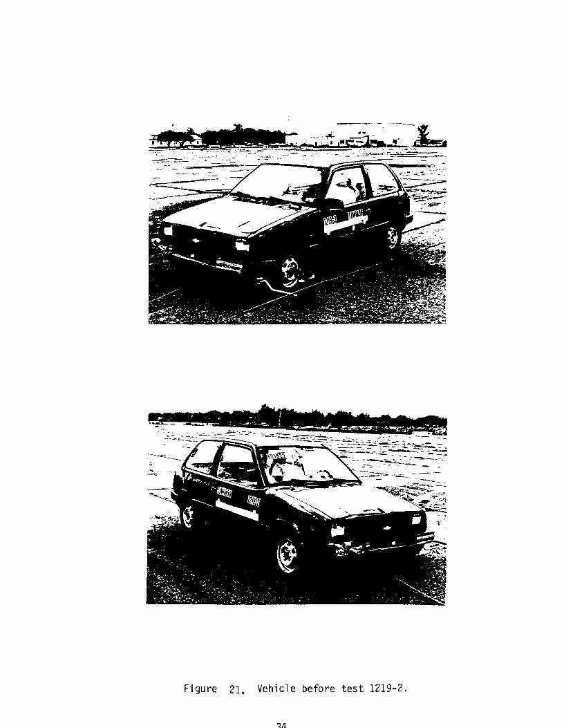
Figure 21. Vehicle before test 1219-2.
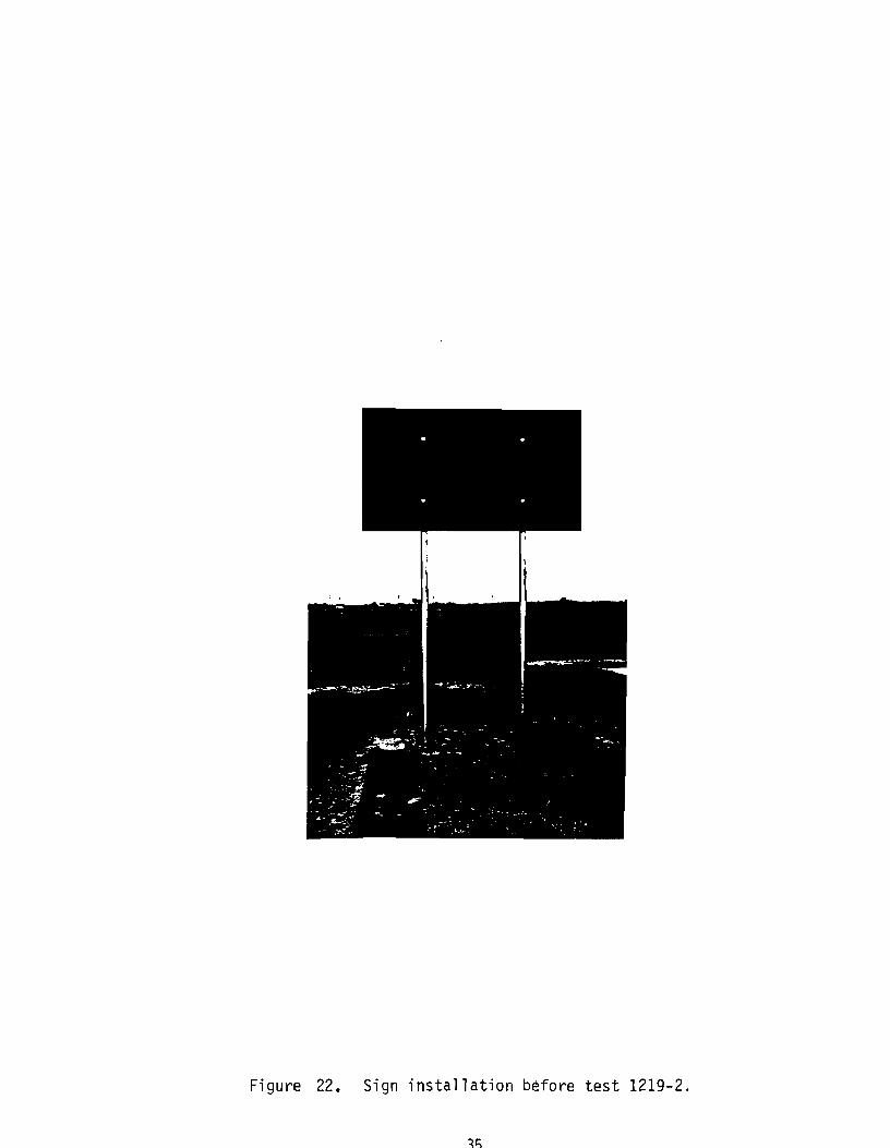
Figure 22. Sign installation before test 1219-2.

0.000 s
0.028 s
0.055 s
0.083 s
Figure 23. Sequential photographs of test 1219-2.
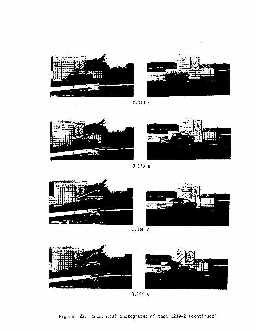
0.111 s
0.139 s
0.166 s
0.194 s
Figure 23. Sequential photographs of test 1219-2 (continued).

Figure 24. Sign installation after test 1219-2.

~l d l...m.-lbWa_ ~~ ~~ :.:....~--~. . ........ .:!....,.-.,~.~.:..;
rl -
-~~,#. " ,~ '-
Figure 25. Vehicle after test 1219-2.

.,
........... -.iIIIl..- ". ~ .. ..,.... ~r;u, .~I"'#'" ...
0.000 s
Test No. . . . Date . . . . . Test Article
Support. . .
Embedment ..
Vehicle ..... Vehicle Weight
0.055 s
· 1219-2 · 08/22/91
. . Texas Generic Sign Anchor Installation · 0.065 in x 3 in
1026 round steel tube · 28 in driven
(NCHRP S-2 soil) .. 1986 Chevrolet Sprint
Test Inertia. . . .1,800 lb (817 kg) Gross Static ....... 1,970 lb (894 kg)
Vehicle Damage Classification TAD 12FD-2 SAE . . . . . . . . . . . 12FDAWl
0.111 s
Impact Speed .... . Change in Velocity .. . Change in Momentum •... Vehicle Accelerations
Max. (0.050-sec Avg) Longitudinal .... . Lateral ...... .
Occupant Impact Velocity
0.166 s
.. 64.6 mi/h {103.9 km/h} 1.5 mi/h ( 2.5 km/h)
126.0 lb-s
.-3.2 g 1.4g
Longitudinal ........ N/A Lateral .......... N/A
Occupant Ridedown Accelerations Longitudinal ........ No Contact Lateral .......... No Contact
Figure 26. Summary of results for test 1219-2.

([)
w W 0:::: CJ W O(\J
"<T I
1219-2 r
1219-2 p
1219 2 y
Axes are vehicle fixed. Sequence for determining orientation is:
1. Yaw 2. Pitch 3 . Roll
1 .2 1.6
Figure 27. Vehicle angular displacement for test 1219-2.
41
1
I:. ,J
0- ItrI~~ ~
I:. -.7
1
15
0 0.1
LA ~tR ,OJ .f'l U
'I f 'V
.-_ .... ,
H>_.~_ ...........
0.2
CRASH TEST 1219-2 Class 180 Filter
. .......
~ ..bA..i...A A.A Ml. .f'< .if.. M. \II' • "'N' :
"If 11- :
)
......
1
0.3 0.4 0.5 0~6 Time (seconds)
1- 50 msec. avg. I
"'" 1ft Ii "''V
. ......
:
0.7 0.8
Figure 28. Longitudinal accelerometer trace (1219-2).
A 1ft R A. !''IT .......
0.9 1

...-.. Vl
" en --= 0 -..-I ~ C';I 1-4
+::> Q) -LV Q)
8 -< -~ Q) ~ C';I
......:l -4
0.1 0.2
Figure
CRASH TEST 1219-2 Class 180 Filter
0.3 0.4 0.5 0.6 Time (seconds)
1- 50 msec. avg. I 29. Lateral accelerometer trace
0.7 0.8 0.9 1
(1219-2) .

---rLl 0\
b.O '-'
= 0 .~ ....,;I
~ (I.)
~ -~ ~ (.)
< -~ .~
t! <U
>
CRASH TEST 1219-2 Class 180 Filter
10~----~----~----~----~------~----~----~----~----~----~
5
-1

Figure 31. Vehicle b~fore test 1219-5.
45
- --: .. ; ..... .. ,:.-....
Figure 32. Sign installation before test 1219-5.
46
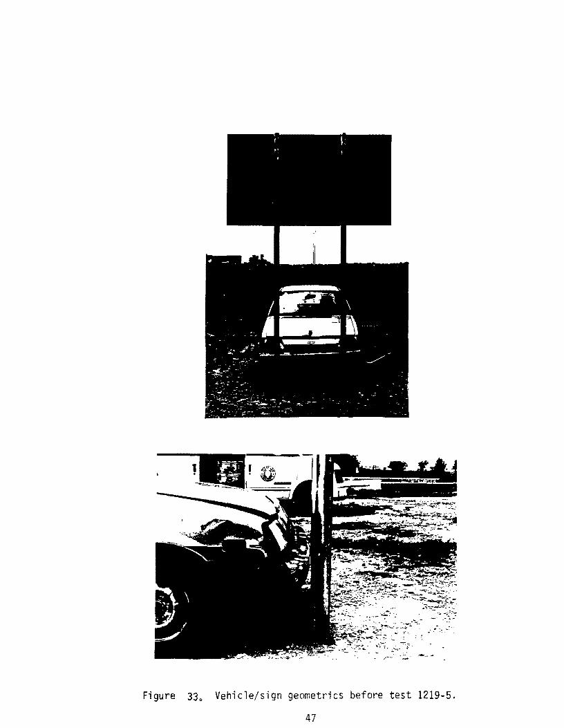
Figure 33 0 Vehicle/sign geometries before test 1219-5.
47
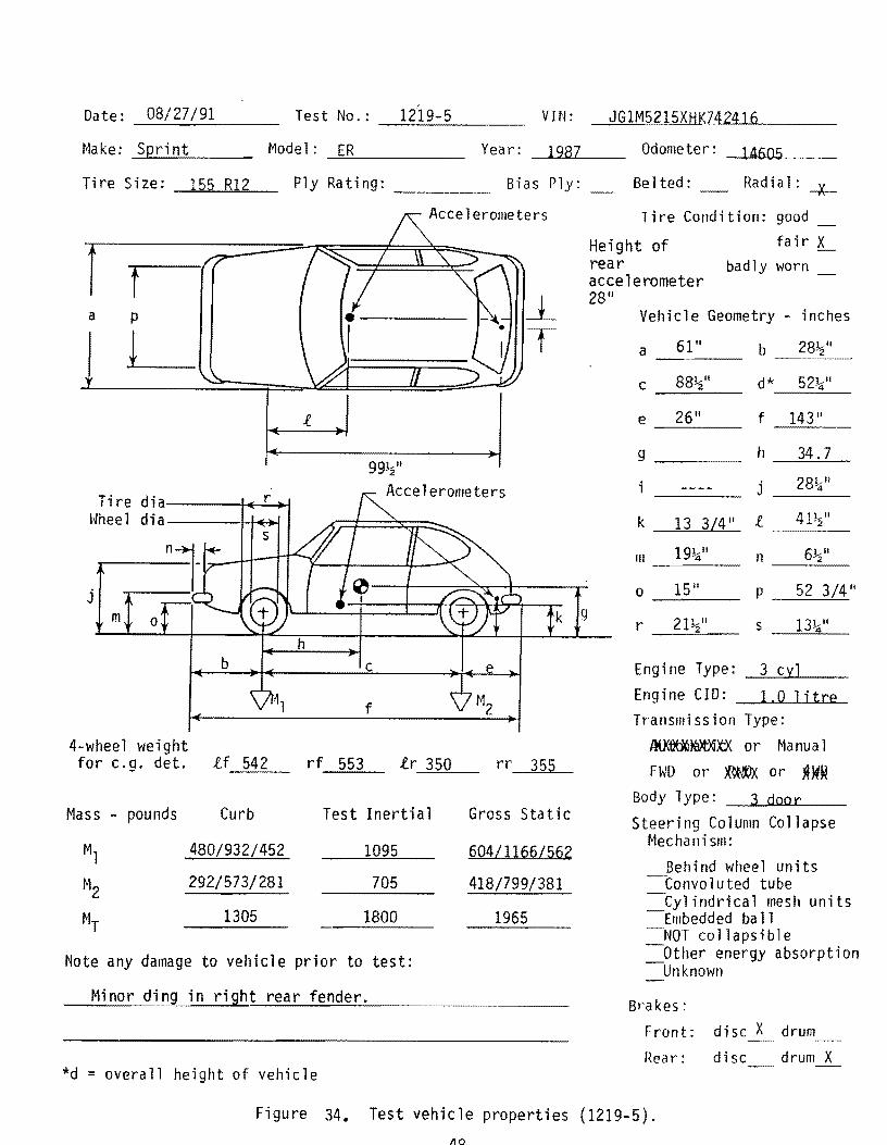
Date: 08/27/91 T est No.: _.::..:12::..:'1:.:9;,....-..=..5 ___ _ VIN:
Make: Spri nt Model: ----!::.E!..!..R ____ _ Year: 1987
Bias Ply: Tire Size: 155 R12
r f a p
±-
Tire d i a----f.('---!...r-4oo-l ~~heel dia----+-J.~
j m
b
4-wheel weight for c. g. det. if
Mass - pounds Curb
Ml 480/932/452
M2 292/573/281
MT 1305
Ply Rating: ____ _
rf 553
Accelerometers
99~"
Accelerometers
c
f
ir 350
k
Test Inertial Gross Static
1095 60411166/562
705 418/799/381
1800 1965
Note any damage to vehicle prior to test:
Minor ding in right rear fender.
*d = overall height of vehicle
9
JG1M5215XHK742416
Odometer: 14605
Be lted: Radial: -X-
Tire Condition: good
Height of rear
fair badly worn
aeee lerometer 28"
Vehicle Geometry - inches
61" a ___ _ b 28~"
c 88~" d* 52%i"
e 26" f 143"
g---- h 34.7
j 28%i"
k 13 3L4 11 .t 41~"
111 19%i" n 6~1I
0 lS 11 p 52 3/4"
r 21~1I s 13~"
Engine Type: 3 cyl Engine CID: 1.0 litre Transmission Type:
JlU(OO(]W.:tX or Manua 1
FWD or ~ or ~W~
Body Type: 3 door Steering Column Collapse
Mechanism: Behind wheel units
-Convoluted tube -Cyl indrieal mesh units -Embedded ba 11 -NOT collapsible -Other energy absorption -Unknown
Brakes: Front: disc X drum Rear: disc drum X
Figure 34. Test vehicle properties {1219-S}.

0.000 s
0.035 s
0.070 s
0.105 s
Figure 35. Sequential photographs of test 1219-5.
49
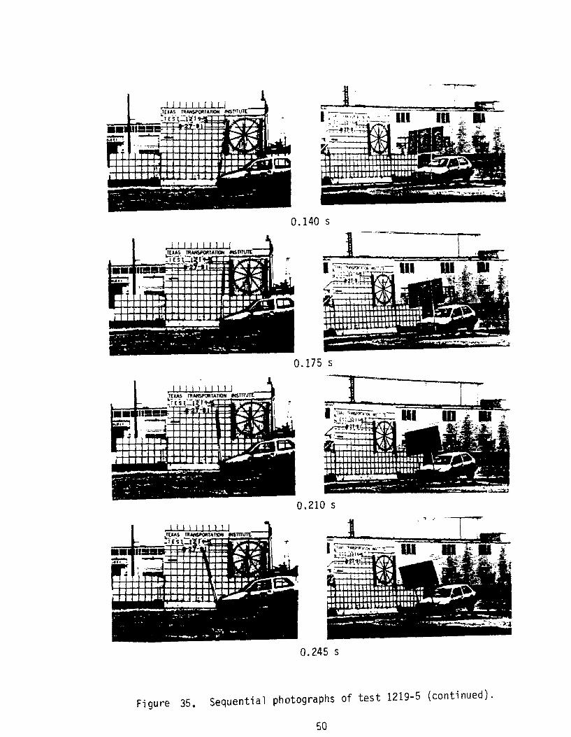
- - t --
0.140 s
0.175 s
0.210 s
0.245 s
Figure 35. Sequential photographs of test 1219-5 (continued).
50
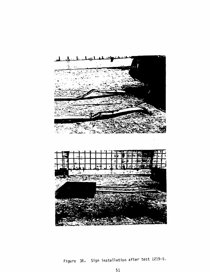
Fi glJre 36. Sign installation after test 1219-5.
51

~ ·r __
~ -~--- ...,--
Figure 37. Vehicle after test 1219-5.
52
U1 W
0.000 s 0.070 s
Test No ... Date . . . . Test Article
. . • . . 1219-5
Support. . .
Embedment ..
. . . . . • 08/27/91
. • • . . . Texas Generic Sign Anchor Installation
. • . . . 0.065 in x 3 in 1026 round steel tube
. 28 in driven (NCHRP S-1 soil)
Vehicle ..... . . 1987 Chevrolet Sprint Vehicle Weight
Test Inertia ....... 1,800 lb (817 kg) Gross Static ....... 1,965 lb (892 kg)
Vehicle Damage Classification TAD . . . .. .... 12FD-2 SAE . . . . . . . . . . . 12FDEWI
0.140 s
Impact Speed. . . . . . Change in Velocity ... Change in Momentum. . Vehicle Accelerations
Max. (0.050-sec Avg)
0.210 s t~
21.0 mi/h (33.7 km/h) 21.0 mi/h (33.7 km/h) 1722 lb-s
Longitudinal ........ -5.4 g Lateral. . . . . . .. .-1.8 g
Occupant Impact Velocity Longitudinal ........ 23.3 ft/s (7.1 m/s) Lateral . . . . . . . . . . N/A
Occupant Ridedown Accelerations Longitudinal ........ -4.3 g Lateral .......... No Contact
Figure 38. Summary of resul ts for test 1219-5.

o
co
(f)
w w' 0:::::t.D
l.9 W o
o
o
C\J I
1219 5 r
1219~5 p
1219-5 Y
.4
T I ME (SECONDS)
Axes are vehicle fixed. Sequence for determining orientation is:
1. Yaw 2. Pitch 3. Roll
1 .2 1 .6
Figure 39. Vehicle angular displacement for test 1219-5.
54
-.. rn ~bJ)
..........
= 0 • -t +01
t: Q) -Q)
(J'l (,) (,)
(J'l < -ctI = .-"'t:S ~
+01 .-t bJ)
= 0 ~
CRASH TEST 1219-5 Class 180 Filter
2.-----~----~----~~----~----~----~-----,------~----~----~
o ......................... 11-, ............................. + .......................... ,
2 .....,! - ...................... .. .......... 1 ...... • .. ·+ ...... :.,' .... · .. · .. · .......... : ............................ .:. ............................ , ............................ , ............................. : ............................ .:. ............................ , ........................... ..
-4 .
-6 ..................... .
-10+-----~----~----~-----r-----+-----+-----T----~----~----~ o 0.1 0.2 0.3 0.4 0.5 0.6 0.7 0.8 0.9 1
Time (seconds)
1- 50 msec. avg. 1 Figure 40. Longitudinal accelerometer trace (1219-5).
----"til boO --= 0
'.;:3
~ <.T1 Q) 0'\ -Q)
~ -~ ;... Q) ...... j
CRASH TEST 1219-5 Class 180 Filter
4~----~----~----~------~----~----~----~------~----~----~
!
:=:::~J::::-::l:-:::~r:l:--1~:J:~:i:~r:::::l~ 1 ...... -.. ..1 ..... ········)--···I·_·······l·················i···········-.1··············--1·························\----[-··.--
{ ~ ~ 1 .! ! 0-II1II"1.,"',,,," ... ... .. .. ..... . ............................... ,.................. .................... . .... ....... .... ..~.. ...... ......... ., ............................ .
: :: : ~ ~. l ~ 1 ~ :: ! :! :
-1 .
I I I I 1 I I I I -5~-----r----~----~r-----+------r-----+----~------r-----~----~ o 0.1 0.2 0.3 0.4 0.5 0.6 0.7 0.8 0.9 1
Time (seconds)
1- 50 msec. avg. I
Figure 41. Lateral accelerometer trace (1219-5).
£: \T
4 I ....
,-., r;n
~I:).Q --= 0 2- \
'.;:I ~ ~ -U1 8 ........
0-:
<: -«:I (,)
'-2 .2-~
> -4
£:
"V 0 0.1 0.2
:
CRASH TEST 1219-5 Class 180 Filter
........
.... , ........................
:
~ ~ ~ ~ ~J\ ~ ~ ~ J~l
,,~ 'Y V'T y v
1t A .~ r -1 i 'IJr<rll"IY
··h ....
:
: ...... :
0.3 0.4 0.5 0.6 0.7 0.8 0.9 Time (seconds)
1- 50 msec. avg. I Figure 42. Vertical accelerometer trace {1219-5}.
Y' "'T""IOl
1
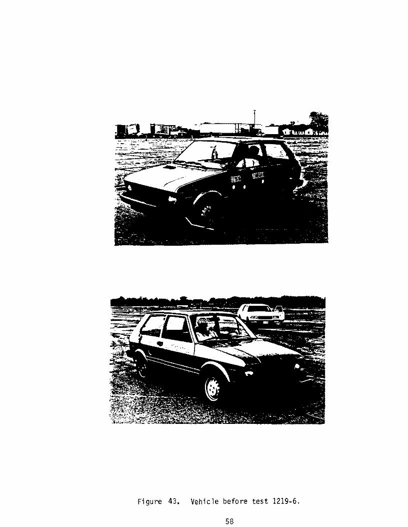
Figure 43. Vehicle before test 1219-6.
58
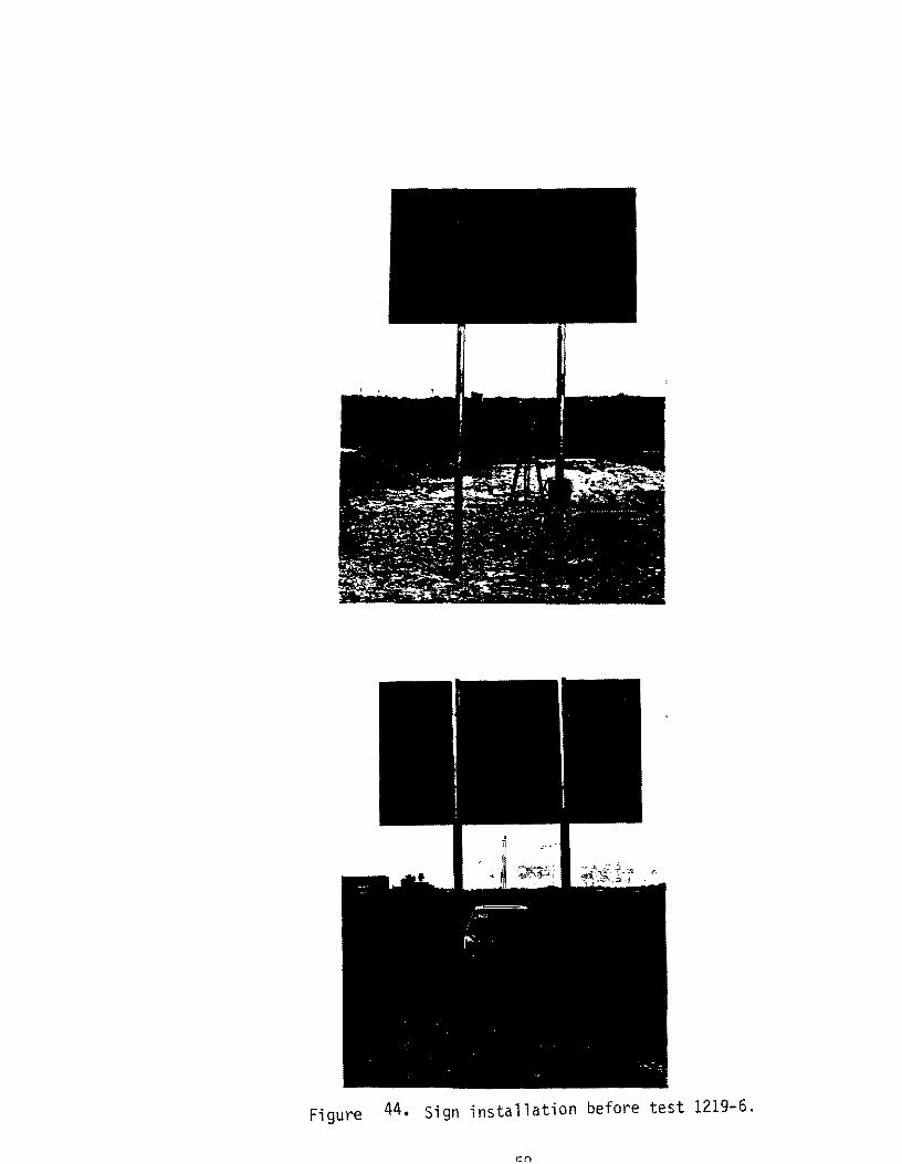
Figure 44. Sign installation before test 1219-6.
en

Figure 45. Vehicle/sign geometries (test 1219-6).
60
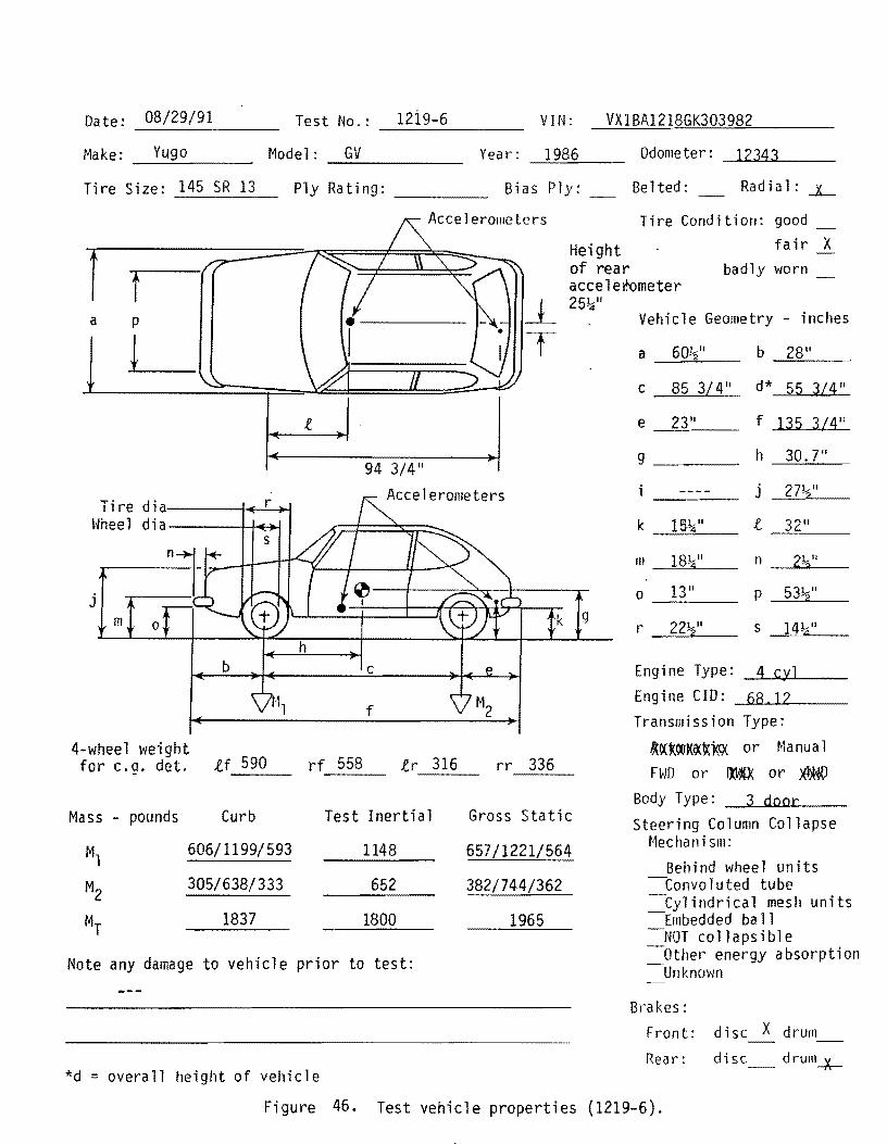
Date: 08/29/91 T t N 12i9-6 es 0.: ________ __ VIN: VXIBA1218GK303982
Make: Yugo -----=----
Tire Size: 145 SR 13
Model: GV Year: 1986 -------Ply Rating: ____ _ Bias Ply:
Accelerolileters
Height of rear
Odometer: ~12 ..... 3=4,-",,3 __ _
Be lted: Radial: -X...-
Tire Condition: good fa ir X
badly worn f t r aeee 1 erometer
a
Tire d i a.------f.of-.!..r-4>-l \~hee 1 d i a ----i-+oHo-I
j
m 0
b
4-wheel weight for e.g. det. tf 590
Mass - pounds Curb
Ml 606/1199/593
M2 305/638/333
MT 1837
Note any damage to vehicle
25!:i"
94 3/4" Accelerometers
k 9
c
f
rf 558 tr 316 rr 336
Test Inertial Gross Static
1148 657/1221/564
652 382/744/362
1800
prior to test:
*d = overall height of vehicle
Vehicle Geometry - inches
c 85 3/4"
e ll
--=::..::..---
9 ___ -
III 18~"
o 13"
r 22~"
b
d*
f
h
j
l
n
p
S
28"
55 3/4"
135 3L4"
30.7"
27!z."
32"
53~"
14~1J
Eng i ne T yp e: -.::;L4-'c .... yl'-J' __ _
Eng i n e C 10: -.loL68u.. ........ l ..... 2 __ _
Transmission Type:
~~~~~~Wx or Manual FWD or m or )El)WQ
Body Type: 3 door
Steering Column Collapse Mechan; SIll:
Behind wheel units --Convoluted tube -Cy1 indrical mesh units -Embedded ba 11 -NOT collapsible -Other energy absorption -Unknown
Brakes: Front: disc X drum
Rear: disc drunl-x--
Figure 46. Test vehicle properties (1219-6).

L P- J .. UI-' ~~-;-;--:-, _i!_ • w
0.000 s
0.035 s
0.070 s
--W UI · ---, - •• I ~ •
0.105 s
Figure 47. Sequential photographs of test 1219-6.
0.140 s
'IlL. I _ i ..
w
0.176 s
0.211 s
It! J ::;: s .... U I -:- -~:~-:;-;- , -.' III W
0.246 s
Figure 47. Sequential photographs of test 1219-6 (continued).
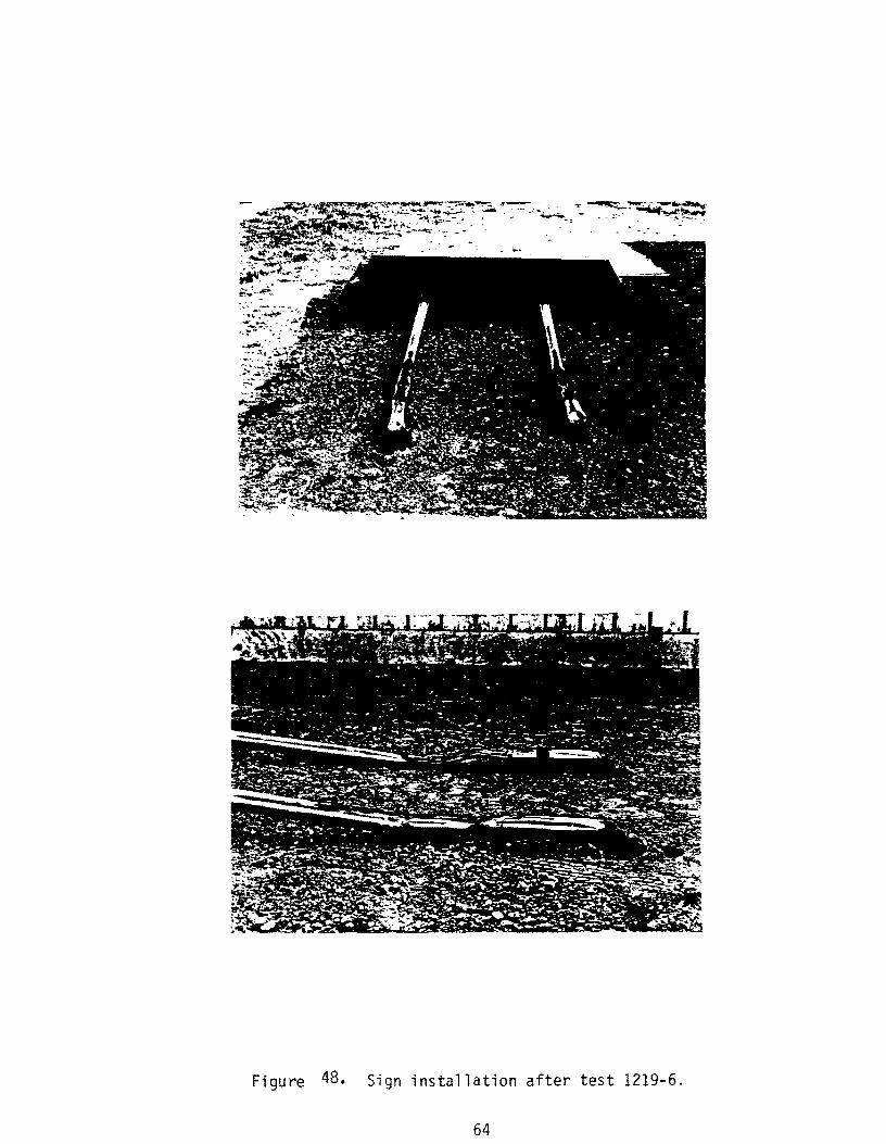
Figure 48. Sign installation after test 1219-6.
64
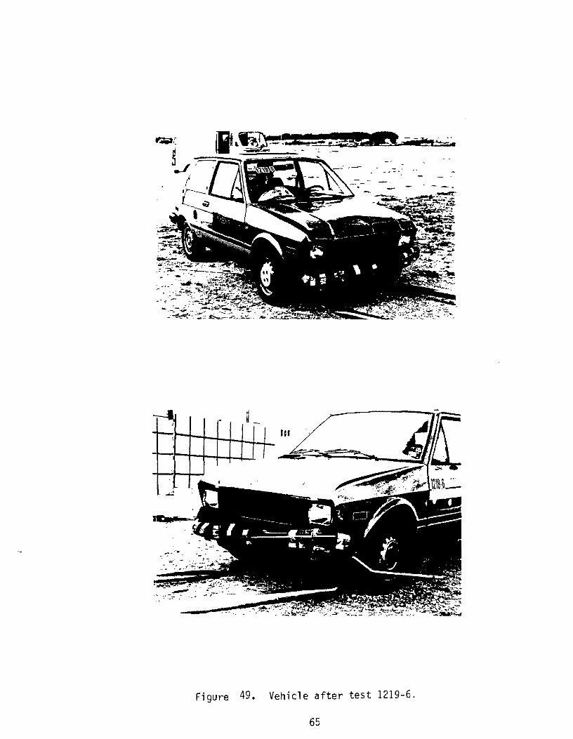
Figure 49. Vehicle after test 1219-6.
65

0.000 s 0.070 s -- -t , ......
, . ,
. " -. '.!' • ~ ~.~ t '11</ ...... • _ , .",a. •
. .. . ·r~ ... ,J ","'~." '.,
. 1219-6 Test No ... Date . . . . Test Article
. . . . . . 08/29/91
Support. . .
Embedment.
Vehicle.. .. Vehicle Weight
. . . . . Texas Generic Sign Anchor Installation
.. 0.065 in x 3 in 1026 round steel tube
. 28 in driven (NCHRP S-1 soil) 1986 Yugo GV
Test Inertia. . 1,800 lb (817 kg) Gross Static ....... 1,965 lb (892 kg)
Vehicle Damage Classification TAD . 12FD-2 SAE . . . . . . . . . . . 12FDEW1
0.140 s 0.211 s .Jl_ .1_
. , .... . " .. .~""J .. '. ~ ••
• f N. .... . ..... ~ , \"... ~tip: -.~ ... ~ , ~
. . ". '" ''': l!:' .~".1'",.", 1\' v ,,'"1
Impact Speed ..... Change in Velocity .. Change in Momentum .. Vehicle Accelerations
Max. (O.OSO-sec Avg)
. 19.8 mi/h (31.9 km/h) 19.8 mi/h (31.9 km/h) 1623 lb-s
Longitudinal ........ -4.6 g Lateral. . . . . .. . 1.1 g
Occupant Impact Velocity Longitudinal. . . . .. . 22.3 ft/s (6.8 m/s) Lateral .......... N/A
Occupant Ridedown Accelerations Longitudinal.. .. -5.4 g Lateral .......... No Contact
Figure 50. Summary of results for test 1219-6.
(j)
w w' 0:::::(') l:)
W o
f-O
w
w U IT
M (LI
(j)
U)
I
01 I
1219 G r
1219 6 p
1219-5 y
, .l
~®'"W~ ~ •• 0-'
.8
----- I ~ Axes are vehicle fixed. Sequence for determining orientation is:
1. Yaw 2. Pitch 3. Roll
1.2 1.6
E (SECONDS)
Figure 51. Vehicle angular displacement for test 1219-6.
67

en co
CRASH TEST 1219-6 Class 180 Filter
4.-----~----~------~----~----~----~----~------~----~----~
,
e i i ~ i
-~ = .....
~ I <8 -2 ........ ....... '" ...... .. ........ t.... .. .. ......... l· .. · .. · ........ · ...... ······t···· .. · .. ·· .... ···· .. ·· .. ···t··· .. ···· .......... ·· .. · .. ·t .. · .. ·· .. ····· .. ········ .. ··j .. · ........ •···· ...... ······t .. · .. · .. ···· .. ············ .. 1· .. ·······• .... ···· .... ···· ..
: : : : : : : : ! : : : : :
I I I I I I I "0 .a -4 ··+HVlllMVll ... .. ...... .. ............ 1.. .......................... 1. ........................... 1 ........................... 1. .......................... .1. ........................... 1 .......................... .1. ........................... .
iii iii i ..... bO = o ~
.::::1, ::::::: I I . I I I ! -6 ..- ..... r-- ...... -1·· ·············-I················-1-·············r············,·······-1--················1····························1·····························
-8~----~----~------~----+-----~-----+----~------+-----4-----~ o 0.1 0.2 0.3 0.4 0.5 0.6 0.7 0.8 0.9 1
Time (seconds)
1- 50 msee. avg. I Fi gure 52. Longitudinal accelerometer trace (1219-6) .
3
,-..... Vl
"'0.0 -..- 1 ... = 0 ..... ..... ~ o ..... Q) -Q) C,.)
0"1 C,.) ~ < -C":l
~ Q) ..... C":l
.....:l
0.1 0.2
CRASH TEST 1219-6 Class 180 Filter
0.3 0.4 0.5 0.6 Time (seconds)
1- 50 msec. avg. 1 Figure 53. Lateral accelerometer trace
0.7 0.8 0.9 1
(1219-6) .

CONCLUSIONS
The installation was found to be acceptable for application in weak soil (NCHRP 230
classification S2) -- tests 1219-1 & 2. However, the current steel post system fails to meet
federal impact performance criteria for low speed impacts for two post installations in strong
soil (NCHRP 230 classification SI) -- tests 1219-5 & 6.
Modifications in anchor design or attachment details and/or other sign post materials
(such as fiberglass or aluminum) may provide a satisfactory solution for multiple post
systems. However, from the results of tests 1219-6 (in which no screws were used to secure
the sign post to the anchor), it does not look like minor changes will cause a two steel post
system to work in strong soil.
The primary difference seems to be the enhanced ability of the anchor system to pull
out under impact loading in weak soil, whereas the post collapses around the anchor and the
anchor is unable to pull-out in strong soil. An anchor to post connection with a combined
pull-out and shear failure mechanism would appear to be a solution to the two soil problem.
In a stiff soil (SI) there would be enough resistance to activate a slip base. In a softer soil
(S2), where a slip base could not function, the anchor pull-out would soften the impact and
allow the system to satisfy impact criteria.
70

APPENDIX A
STATIC LOAD TESTS
FORCE-DISPLACEMENT CURVES
71

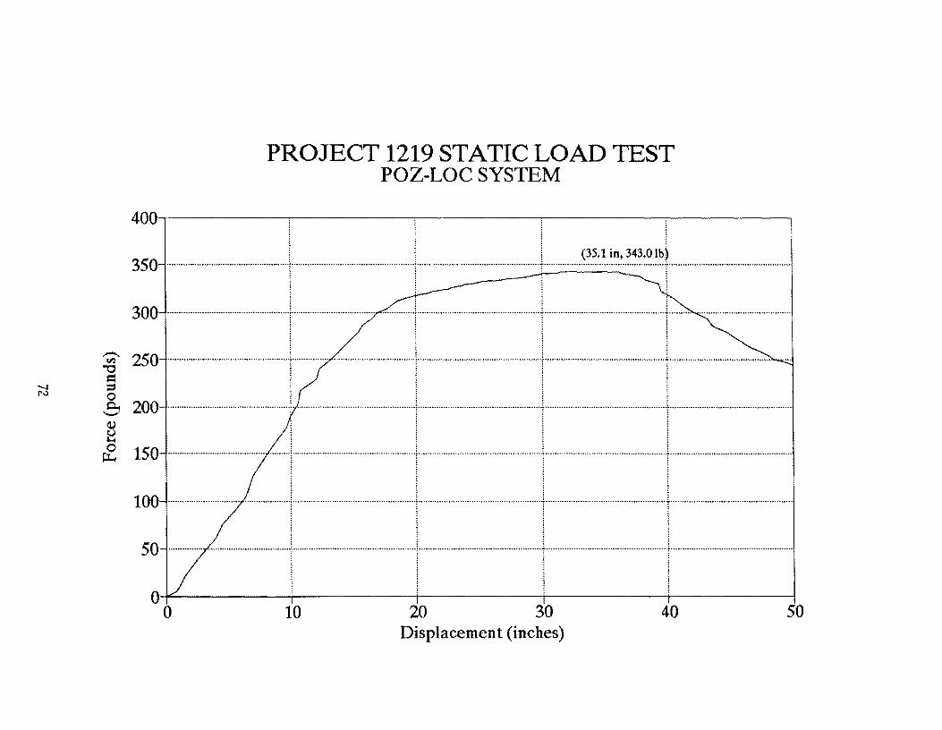
PROJECT 1219 STATIC LOAD TEST POZ-LOC SYSTEM
400~--------~--------~--------~--------~--------~
~ l l (35.1in, 343.0 Ib) 350 .................................................... "[" ................................................... "\" ........ ······ .. ····································t·········· ......................•................... 1" ................................................... .
o o 10 20 30 Displacement (inches)
40 50

PROJECT 1219 STATIC LOAD TEST HWYCOM SYSTEM
400~--------~--------~--------~--------~------~
~ (34.9 in, 362.4 Ib)
350·······1···\1··· 300 ·······--··I··+-·~ ...... ··+················f ........... ' ...................... + ..................................................... j
~ 250 ..................................................... f .................................... , ............... + ............. .. ~ ; ; d : : = ! ! i 200 .. · .. ····_····· .. ·1································· ~ 150 .. · .. · .......... ·· .............. · .... · .. · .. · .. · ...... f .... ··· .... · .... ·~ .... · ............ · ..... ..
! i
100 ................................................. ,!Y •• , ..................................................... : .............................. • .......... • .. I· .. · ........ ~ .... · .. · .......... ·· ...... ·· .. · ...... · .... ·· .......... ~· .. · ................... ..
50 ........................ :1 ........................... , ..................................................... , .... · .... ·· .......... ·· ...... ····f ........ , .... · ....... ··· ...... · ........ · .. ·· .............. · ...... · .... ••·· .. ", .......... · .... · .... ·· .. ··· .... · .. • .. · .. · .. · .... · .... 1
O+---------+---------+---~----T---------r-------~
o 10 20 30 40 50 Displacement (inches)
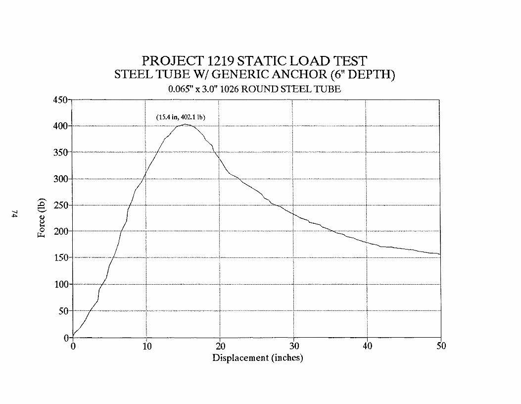
PROJECT 1219 STATIC LOAD TEST STEEL TUBE WI GENERIC ANCHOR (6" DEPTH)
0.065" x 3.0" 1026 ROUND STEEL TUBE 450~--------~--------~--------~--------~------~
; (15.4 in, 402.11b) l I : 400 ....................................................... ·t······················ ..... ····· .. ······· .. ···r······························· .. ···· ................. ")" ..................................... ··················r··································· ................... .
! ! I I 350 ........................................................ j ..................................................... + ........................................................ \ ..... ·························· .. ·······················1 .. ·· ................................................... .
! 1 l
300 ...................................................... T····················· .. ································t·············· ········································1············· ................•.......................... j ....................................................... . i l ~ l
-- j j j j
! ::~:-.::-.:::::=:::r:::-::~~::I::--:::-~::::::~:l~-.:::::~-::: 150-···--·-·--I--L-i---;---
I ! i I 100 -··-----1-1--'-1·-----50-_···-···-t-·····\-lt--O+---------~--------~--------~--------~--------~ o 10 20 30 40 50
Displacement (inches)
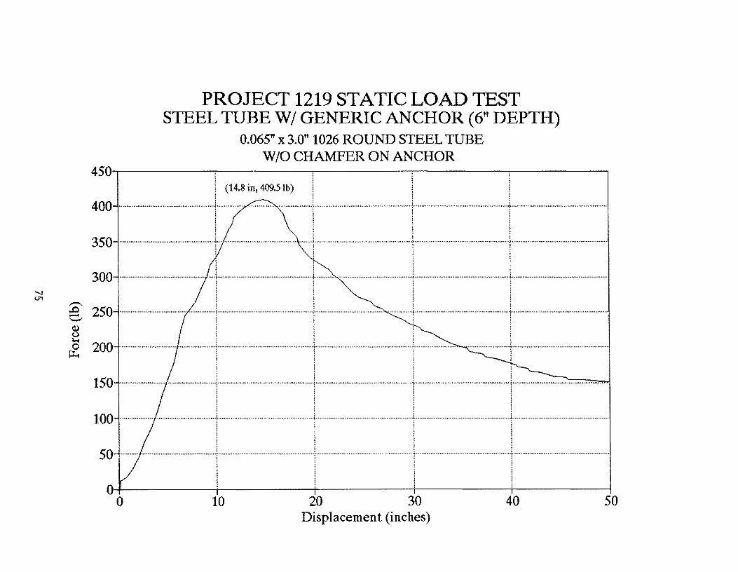
PROJECT 1219 STATIC LOAD TEST STEEL TUBE WI GENERIC ANCHOR (6" DEPTH)
0.065" x 3.0" 1026 ROUND STEEL TUBE WID CHAMFER ON ANCHOR
450~------~·~------~·--------~--------~·--------~
I (14.8 in, 409.5 Ib) I i 400-·1·- ····\·-I··j-········· 350 ..................................................... ; ........................................... · .. · .. ·j ........ ··· .. · .... · .... ·· .. · .. · ........ · ...... ··· .... ·f .... ···· .. ·· .... · .. ·· ........ · ........ · .... · ........ ·f .......... ·· ........ ······ .. · .. ·· ...... ····· ...... · ..
! : ! !
300··········j·····-····i·-···.J······j········--· 1 iii ___ 1 1 1 1
@., 250 ....................................... ·· .... · .. · .. 1 ...... ·· .. · ...... · .. · ............ ···· .. · .. ····· ...... 1·· .. ··· .... · .......................... ·· ........ ···t .. · ...... ···· ...... · .. · .. · .. · .. · .... · .... · ...... · .. ·t .......... · ...... · ................................. ..
~ 200 .................................................. .l. .................................................... ~ ............ · .. · ...... · .... · .......... · .... · ........ ··f ...... ····· ............ · ....................... + .................................................... .
~ iii ! 150 .................................................... \ ..................................................... 1· .... ··········· .. · ...... · .. · .. · .. ··········· ...... ··1·· ........ · .... · .................................... 1-................................................ .
o o 10 20 30 40
Displacement (inches) 50
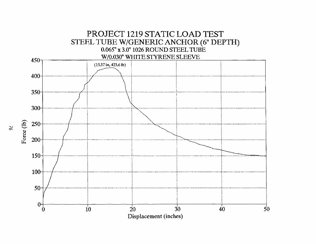
PROJECT 1219 STATIC LOAD TEST STEEL TUBE W/GENERIC ANCHOR (6" DEPTH)
0.065" x 3.0" 1026 ROUND STEEL TUBE 4501~ ________ ~ __ w~ro~.0~30~"~W~H~I~TE~STY~R~E~N~E~S~L~E~E~V~E~ __ ~ ______ ~
I (15.37 in, 425.61b)
400 ······ .. ··············· .. ······························t ........................................ " ........... ~ .... .
350 ······ .. ··············································1 ................................................. .
300 ...................................................... .1. ..................................... ··················t···""··· ................... . ~ ~
~ 250 ·····························--·1·············································l······-,·····~ .. ·············· .......... i ... ··· ................ ··· .. · .............. · ............... + .......................................................... j
8 i i M j j : & 200 ..................................................... "1" ....................................................... _ ......................... ······························t··········
o o 10 20 30 Displacement (inches)
40 50
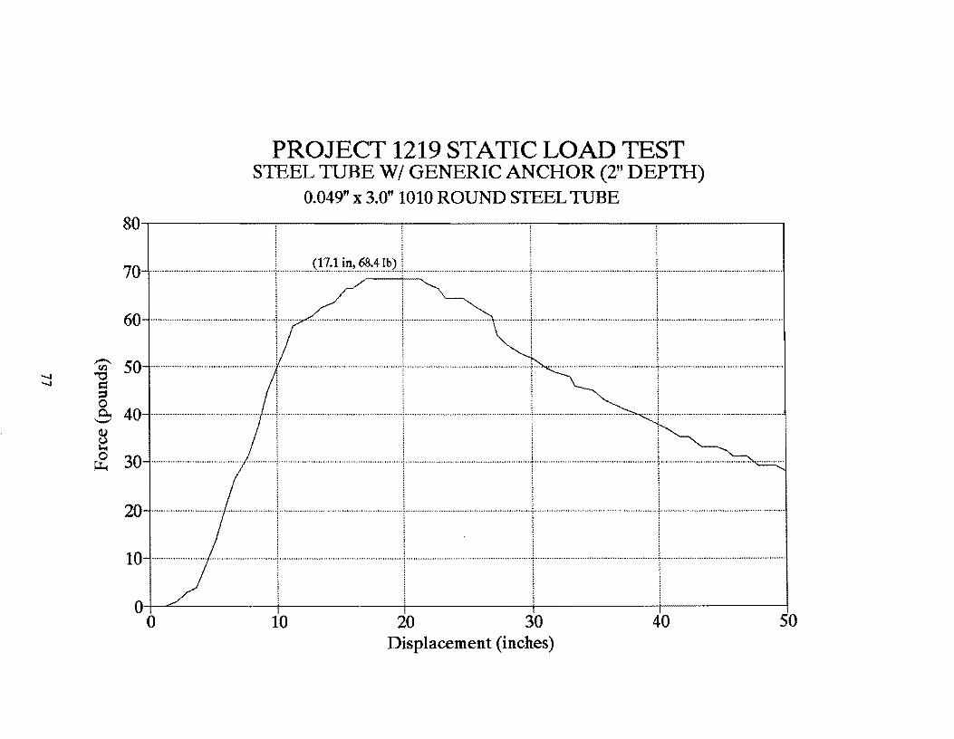
PROJECT 1219 STATIC LOAD TEST S1EEL TUBE WI GENERIC ANCHOR (2" DEPTH)
0.049" x 3.0" 1010 ROUND STEEL TUBE 80~--------~--------~--------~--------~------~
70 ..................................................... \ ............... (~?~~ .. ~~L~:~··~~)··I·············· .. ·····································1········ .. ·················· .. · .. •··· .. ·············f················ .. ········ .......................... . ~ !!
60-·····11··-\····· ! i:
"Ul' 50 ..................................................... ! ! · .. ···········································f······· ............................................. . "'d =I =' o C 40 .............................................. . .... "1" ................................................... .
§ ~ 30 ....................................... .; .............. ; ....................................................... ; .......................... · .... ·· .. · .. ···· .... ··········i···
20 ............................ ..
10 ············ .. ···· .. ···f .. · .... • .. ····•· .... ······ .. ·; ........ ··· ............................... ..
O+-~------+---------+---------+---------+-------~
o 10 20 30 40 50 Displacement (inches)
-\'I) "tj
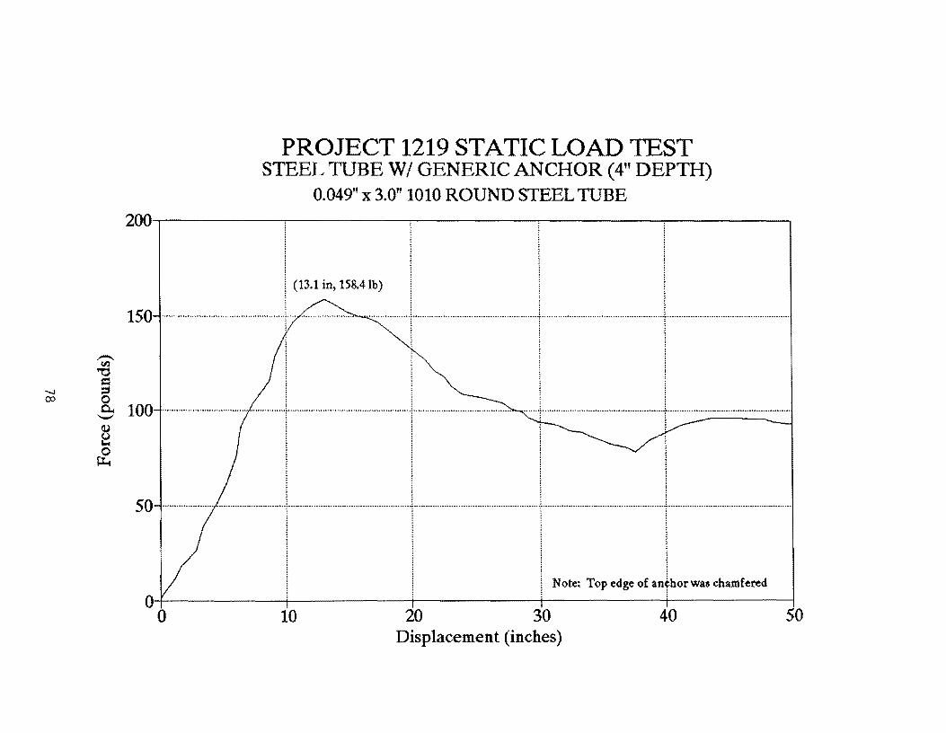
PROJECT 1219 STATIC LOAD TEST STEEL TUBE WI GENERIC ANCHOR (4" DEPTH)
0.049" x 3.0" 1010 ROUND STEEL TUBE 200'~--------~--------~----------~--------~--------~
I !
! ·r·ll-····· 150 ................... " ............ ...................... , .... yL. .................... ..
(13.1 in, 158.41b)
1 ~
t:I
} 100 .. ··_-1··1
~ I I
I ! 1 ~ : : : l ...... 'j .................................................... 1' ................................................... .
50-· -··_··I·---··I-··-·r·····_·,······· j j ! Note: Top edge of an¢horwas chamfered ~ l ! !
0+---------~--------~----------4----------+--------~ o 10 20 30 40 50
Displacement (inches)

PROJECT 1219 STATIC LOAD TEST STEEL TUBE WI GENERIC ANCHOR (4" DEPTH)
0.049" x 3.0" 1010 ROUND STEEL TUBE 200·~--------~--------~--------~--------~------~
l (127 in, 16231b) .
I !
150'--1\-1·1-·_· ~ I I' t 1 OO---I-·--t·~·l-·· o :: I
~ I I ' 50 ......................... ···· .............. ···· .... 1 ......... ···.· .... ··.·· .............................. \ ....................... ······························f····················································t························ ............................ .
i ill : : ; : ! : : :
I I I I O+---------+---------+---------+---------r-------~
o 10 20 30 40 50 Displacement (inches)
()) o
PROJECT 1219 STATIC LOAD TEST STEEL TUBE WI GENERIC ANCHOR (6" DEPTH)
0.049" x 3.0" 1010 ROUND STEEL TUBE 200·~--------~--------~--------~--------~------~
I (10.2 in, 182.9Ib) .
175-·······_················ ·r-·· ··············_·············i--·····_································1···········_·························· .......... j-_............._ ... .
150.._...I--I---L....\-.
i 125-·_··\-1--1-··1-~ 100 ........................................... · ........ 1 ................ · .................. · .. · .. · .. ·.. .. ....................................................... 1 ..................................................... [ ................................................... ..
~ 75 ........-.I-...I-.l..---J..-I i ~ I ~ 1 . l
O+---------+---------+---------T---------~------~
o 10 20 30 40 50 Displacement (inches)

PROJECT 1219 STATIC LOAD TEST HWYCOM POST W/GENERIC ANCHOR (6" DEPTH)
200~--------~------~~------~--------~--------~ i (21.0 in, 193.6Ib)
180 ..................................................... \ ....... ···· .. ·· ................ ·· .. ········· .... ·· .. ·1·· .... ·· .. ··· .......... ····· .......................... [ ................................................. ..l .................................................. .
160·····\·_··1·1···"' ........ , ................ ···· .. · .......... ·· .... .. 140 ..................................................... \ ..................................................... \ ............................................ .
..-.. . .
~ 120 ........ ·· ...... ··· ...... · .... · ...................... 1· .. · .. · .......... ·· .... ··· .. ··· .. ····· .......... · .... 1· .. ·· .. · .. · .......... ·/·· ........ · ............ · .... ~ .... ····· .. · .... ·/· .............. · .... · ........ · .... f· ............ · .. · .... · .. · .. ··· ............ · ............ 1 ~ : i ~ i ! ~ 100-.-
1, .................................................... ;
~ ~ 80 ..................................................... ! .................................... ·f .. · ...... · .... ·;· .... ·· .. ··· .. · .... ·
60 ..................................................... ! ................ . 40 ............................................. .
20 .................... "'" ~ ............................. ;
O+---------~------~~------~---------+--------~ o 5 10 15 20 25
Displacement (inches)
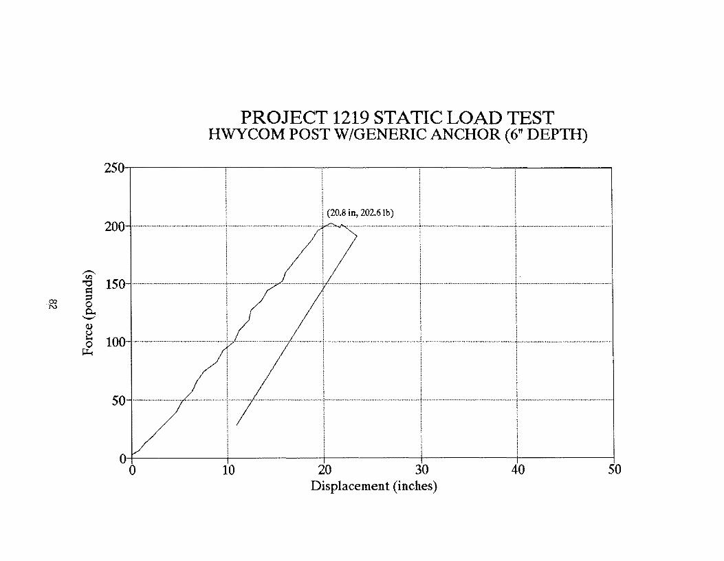
PROJECT 1219 STATIC LOAD TEST HWYCOM POST W/GENERIC ANCHOR (6" DEPTH)
250'~--------~--------~------~--------~--------~
I (20.8 in, 202.6Ib) 200 ·················· .. ················ .. · .. ·· .... ·····t······ .............................................. ! ... .
~ I 1150 ·· .. · .. --r.··········· ··-1.;······ .. · .. · ...... ··· .... · ..
~ 100 ................................................... + ............................... .; ................. +....... .......................................... . ....................................................... -f.............. .. ............ • .. ·· .. ·· ...... ·· .... ·1
~
50·-·············· ···················-1···
I O'+---------~------~~------~---------+--------~ o 10 20 30 40 50
Displacement (inches)

APPENDIX B
TENSILE COUPON
LOAD-STRAIN CURVES
83


TENSILE COUPON TEST 1219-1A 0.085" x 3.0" 1026 DOM Steel Tube
3.5-.-----:---------.,.-----:------..,.--------:--------:------...,----,-------. 1
I i
O+---~-~--~--~----r---~--T----r--~ o 0.005 0.01 0.015 0.02 0.025 0.03 0.035 0.04 0.045
Strain (in/in)

Co <.n
TENSILE COUPON TEST 1219-1B 0.085" x 3.0" 1026 DOM Steel Tube
3.5-,-----;-1 -----,-----,------:----:-------,------,-----,-------,
~
0+---+---~~--4---+---~--~---+---~-~
o 0.005 0.01 0.015 0.02 0.025 0.03 0.035 0.04 0.045 Strain (in/in)

.til
TENSILE COUPON TEST 1219-2A 0.065" x 3.0" 1026 DOM Steel Tube
3~--------~--------~--------~--------~--------~
!
205---- 0- 0--I-oo---oo+---!----! !
'I I i . I .
~ ~ ~ ~ : : : : ! ! : :
0+---------4---------~--------~---------+--------~ o 0.005 0.01 0.015 0.02 0.025
Strain (in/in)

TENSILE COUPON TEST 1219-2B 0.065" x 3.0" 1026 DOM Steel Tube
2.5-.--------:--------:----------,.---------:-------,
I ~ , .. : 2 ....................................................... j .................................................... ·····t················································ ....................................................... ··············1············ .. ·························· ................ .
I. I, i !
~ i i : :
l ~
o+-----+-----+-----~----~-----~ o 0.005 0.01 0.015 0.02 0.025
Strain (in/in)

TENSILE COUPON TEST 1219-3A 0.049" x 3.0" 1018 Steel Tube
1.4-.------~-----.,.------------,---------:--------,
o o 0.005 0.01
Strain (in/in) 0.015 0.02 0.025
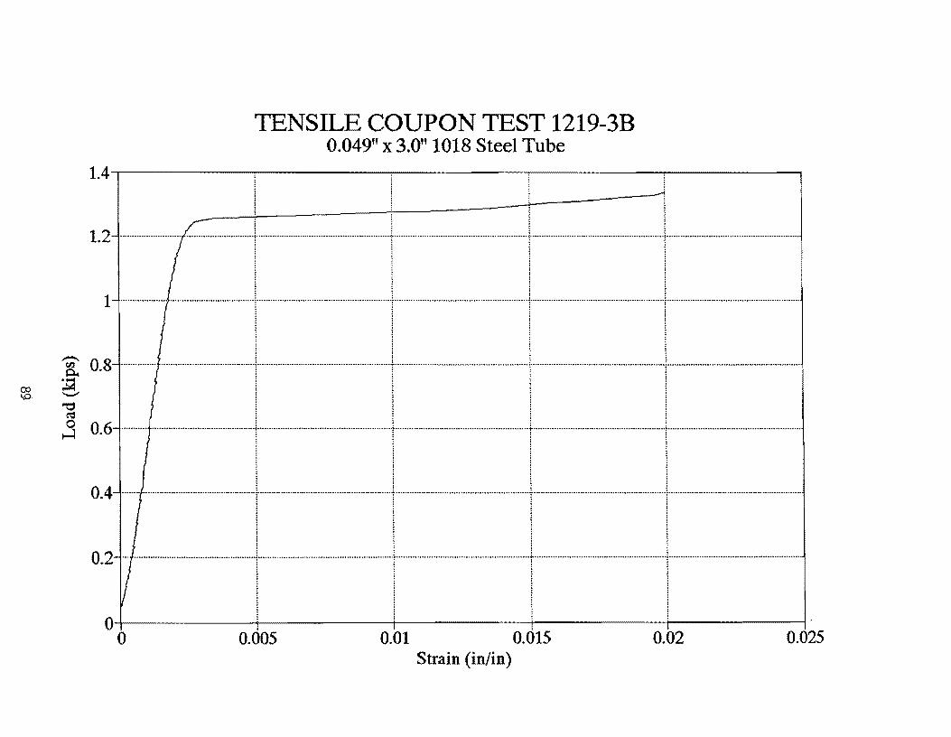
TENSILE COUPON TEST 1219-3B 0.049" x 3.0" 1018 Steel Tube
1.4-,-------.,--------,------..,-------,---------.
1.2 .......................... ·····························1·························································t·························································1················ .......................................... ! ........................................................ .
1---····· ._.....---1---1-1---1---. I I I I
~ 0 8 ....................................................... L ...................................................... .1 ......................................................... 1 ........................................................ .1 ........................................................ . ~ . ! ! ! I -- I I I I ~ 1 l l l :3 0.6 ........... ···········································t························································t·························································r························································1 ........................................................ .
i ! i ! : : : : : : : : ! i ! !
o+-----~-----+-----~----~----~ o 0.005 0.01 0.015 0.02 0.025
Strain (in/in)
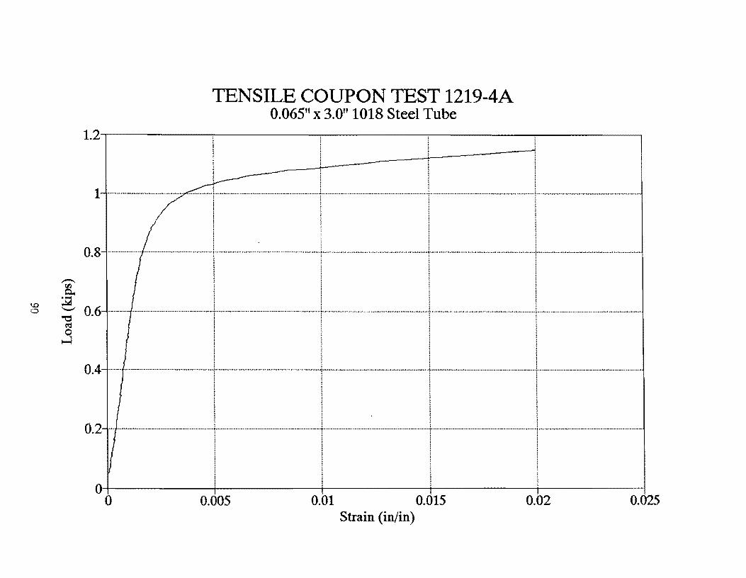
TENSILE COUPON TEST 1219-4A 0.065" x 3.0" 1018 Steel Tube
1.2-,--------,-------.,..---------:---------,..-------,
o o 0.005 0.01
Strain (in/in) 0.015 0.02 0.025
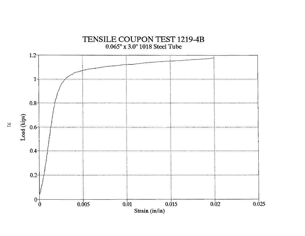
TENSILE COUPON TEST 1219-4B 0.065" x 3.0" 1018 Steel Tube
1.2,---------,--------,---------.--------.-----
_---l---------i--------~! .. ~ ,
, i
1······_···\··1·····1·····-1···· : : : 1
! ~ i i
0.8 ............. ",."" ..... , ... " ........ " .. """ ...... \ ... " ....... ,, ..... """",.""."." ..... ".".""",f""" ... ".,,"",, ......... ,,",, ... · .. ···,···"···"··t··· .. ·····,,·,,······ .. ,,""",,·· .. ······,,,, .. · ....... \."" .. "."""" ........... """"""""" .. ",,.,,.
~ 0.6-···-········-1·-1··1··········1········· Q iii i ~ I l j !
0.4 ·_···_·····1-······1·1··1·_··_··-i i ~ i
I I I I i ~ ! ~
O+-----+-------+--------~--------~-----~ o 0.005 0.01 0.015 0.02 0.025
Strain (in/in)
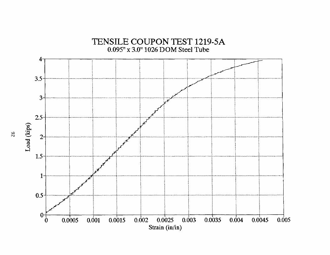
TENSILE COUPON TEST 1219-5A 0.095" x 3.0" 1026 DOM Steel Tube
4.---~----~--~----~----~--~----~--~----~--~
0+----4----4---~----~----~---+----+----+----+---~
o 0.0005 0.001 0.0015 0.002 0.0025 0.003 0.0035 0.004 0.0045 0.005 Strain (in/in)

1..0 W
TENSILE COUPON TEST 1219-SB 0.095" x 3.0" 1026 DOM Steel Tube
4.5-,-------,--------,----------,-------------,-------------,
4-_......1·······I···r-·--·'····· 3.5-······-·-1·······+·······_·-1-·····+····_·
I I i I 3 ............................... ··········· .. ············1····· .. ······················· ............................ \ ........................... ·········· .. ··················1··· .. ···································· .. ·· .. ···········1············· .. ······ ... · ............................... .
1 : : : 1 : : : : : : :
1 ......... ··············································1······· .................................................. {. ... ··························:··························t ......................................................... \ ........................................................ .
o 0.005 0.01 0.015 0.02 0.025 Strain (in/in)

TENSILE COUPON TEST 1219-6A 0.065" x 3.0" 1018 Steel Tube
1.21--t--==~======r===========II---l ~
1 ........................................................ j ................................................... ······f······································· .. ······· ........ + ............................................. ············1········································· ............... .
I I I I 0.8-...............--.......-1--.--...-..-1-.1---.......-1----.........-
~ ! ~ ~
0.4.--.---.---\------.. ]---.[.---... \.-.---.---: : : :
l ~ 1 ~
0.2 ................................................. · .. · .. 1 .... · .... · .... · .. ··· .... · .. · .. ·· ................ · ........ t ...................... ·· .......... ···· .......... ·· .. ·····t .. ·· .... ·· ............................................... , ....................................................... ..
I I I I i l ~ ~
0+---------4---------~--------·-+---------+--------~ o 0.005 0.01 0.015 0.02 0.025
Strain (in/in)
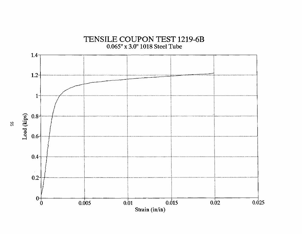
TENSILE COUPON TEST 1219-6B 0.065" x 3.0" 1018 Steel Tube
1.4...---------,-------,--------:--------:-------,
i , 1.2 ......................................................... I···················································· ..... + ........................................................ !.......... . ............................. , ........................................................ .
1-··-·--;··-··j--I·-----·-·I·········----~ 1 ~ ~ : : : :
~ ; ~ ; : 1 ! i
I I I I
0+-----4------~------+---------+-------~ o 0.005 0.01 0.015 0.02 0.025
Strain (in/in)

TENSILE COUPON TEST 1219-1X 0.065" x 3.0" 1026 DOM Steel Tube
3~----~----~----~----~----~----~----~----~----~
25 .=--L~==JL~==~: ====~====:t=====t=====r==~ : . -""'r'r"r'-'!--'I"-\'I" ~ ill 1 l 1
~ 2--.···.·\·······I.--r.-.. ·1.··.I-I-l··········-I··· ... f 1.5 - .... -........1.--.....1....--1........·-11··...-1-... 1"-,-1",,,-
1-··············\······j··I·\·II·\·\··_··· I I I I I 1 I I
I I I I I I I I
o 0.005 0.01 0.015 0.02 0.025" 0.03 0.035 0.04 0.045 Strain (in/in)
