technical report three - pennsylvania state university
TRANSCRIPT
Christopher Kelly
Technical Report Three Mechanical Systems and Existing Conditions
Evaluation
SALK HALL ADDITION
The University of Pittsburgh, Pittsburgh
Christopher Kelly, Mechanical Option
Professor James Freihaut, Advisor
Fall 2010, Senior Thesis Design Project

Christopher Kelly Technical Report Three → 2010
2
TABLE OF CONTENTS
Executive Summary……………………………………………………………….3
Mechanical Systems Description
Introduction………………………………………………………………...4
Design Objectives and Requirements……………………………………...4
Site and Budget……………………………………………………………..4
System Initial Cost………………………………………………………….5
Lost Space…………………………………………………………………..5
Energy Sources……………………………………………………………..6
Design Air Conditions……………………………………………………...6
Equipment Summaries……………………………………………………...7
System Operation
Air Side Schematics and Operation Strategy………………………………10
Chilled Water Loop Schematics and Operation Strategy…………………..11
Hot Water Loop Schematics and Operation Strategy……………………...13
Data Found in Previous Reports
Ventilation Requirements………………………………………………….15
Thermal Loads and Energy Use…………………………………………...16
LEED Analysis…………………………………………………………………...19
Overall Evaluation………………………………………………...……………...21
Christopher Kelly Technical Report Three → 2010
3
Executive Summary
This report summarizes the existing conditions of the mechanical systems found within the Salk Hall Addition. The University of Pittsburgh designed the addition to existing Salk Hall in order to accommodate increased learning in the Schools of Dental Medicine, Pharmacy, and the Graduate School of Public Health. Many factors influenced the design of the building, namely the constraints imposed by its laboratories and their support spaces. This is the final technical report within the Architectural Engineering Senior Thesis program.
After reviewing this report, it will be clear how the mechanical systems operate within the Salk Hall Addition. The existing systems have been evaluated and have been determined to meet the criteria set forth by ASHRAE design standards as well as the University of Pittsburgh’s lab standard. It will become clear, however, that the conventional VAV system designed for the Salk Hall addition could be improved. Keep in mind that the current design has been simulated and operates within an acceptable range of the per unit operating cost of neighboring buildings on campus. However, the current VAV system could be improved by using condensing boilers and heat recovery chillers. This design could ultimately provide “free reheat” for the terminal reheat coils in the VAV units. Chilled beam systems have also recently been proposed for laboratory designs. These options will be explored in the final proposal as well as in the AE Senior Thesis design phase next semester.

Christopher Kelly Technical Report Three → 2010
4
Mechanical Systems Description
Introduction
The scope for the Salk Hall Addition includes the construction of a new research tower of approximately 81,100 gross square feet connected to the existing Salk Hall. The project will create the much needed additional research laboratories and related ancillary spaces for the Schools of Dental Medicine, Pharmacy, and the Graduate School of Public Health.
Design Objectives and Requirements
The project scope includes renovations, upgrades, extensions, expansions and/or replacement of the following systems: HVAC, electrical, fire protection, water, waste, telecommunications, data, security, controls, and laboratory specialty systems in Salk Hall and the Salk Hall Annex. The underlining goals are to improve system function and increase energy efficiency, meet applicable Codes, and accommodate upgrades and the expansion of the buildings’ research, teaching, administrative, and auxiliary facilities.
Site and Budget The site for the proposed Salk Hall Addition is located on the University of Pittsburgh’s main campus and is situated within the 4th Ward of the City of Pittsburgh, Pennsylvania. The proposed site is located within a square city block bounded to the north by Allequippa Street, to the east by Sutherland Drive, to the south by Terrace Street, and to the west by Darragh Street. The city block is approximately 6.5 acres in size and consists of two properties owned by the University of Pittsburgh. The proposed project area is currently under conditions of an existing bituminous asphalt pavement parking lot with a heavily wooded hillside. Total building construction is estimated to cost around $42 million.

Christopher Kelly Technical Report Three → 2010
5
System Initial Cost
The estimated cost for the HVAC system in the Salk Hall Addition is about $3.5 million. This value would yield a unit cost of $43.15 per square foot. The estimated cost of the plumbing system is around $1 million. The estimated first costs of the HVAC and plumbing systems are $225,000 and $44,000, respectively. The total cost of the combined HVAC and plumbing systems is around 10.7% of the estimated total building cost.
Lost Space
The lost space due to mechanical systems is summarized in the following table. The first floor and the mechanical penthouse hold a majority of the HVAC and plumbing equipment. Shaft area was calculated on a floor‐by‐floor basis since shaft openings have accordingly as the ducts were sized to yield a minimum duct construction cost while still maintaining an appropriate aspect ratio.
Mechanical Spaces
Floor Lost Space (GSF) Type %
Total 1 1730 Equipment Room 20.00%2 150 Shafts 1.70% 3 250 Shafts 2.90% 4 250 Shafts 2.90% 5 250 Shafts 2.90%
Penthouse 6000 Equipment Room 69.50%Total 8630 100%
Christopher Kelly Technical Report Three → 2010
6
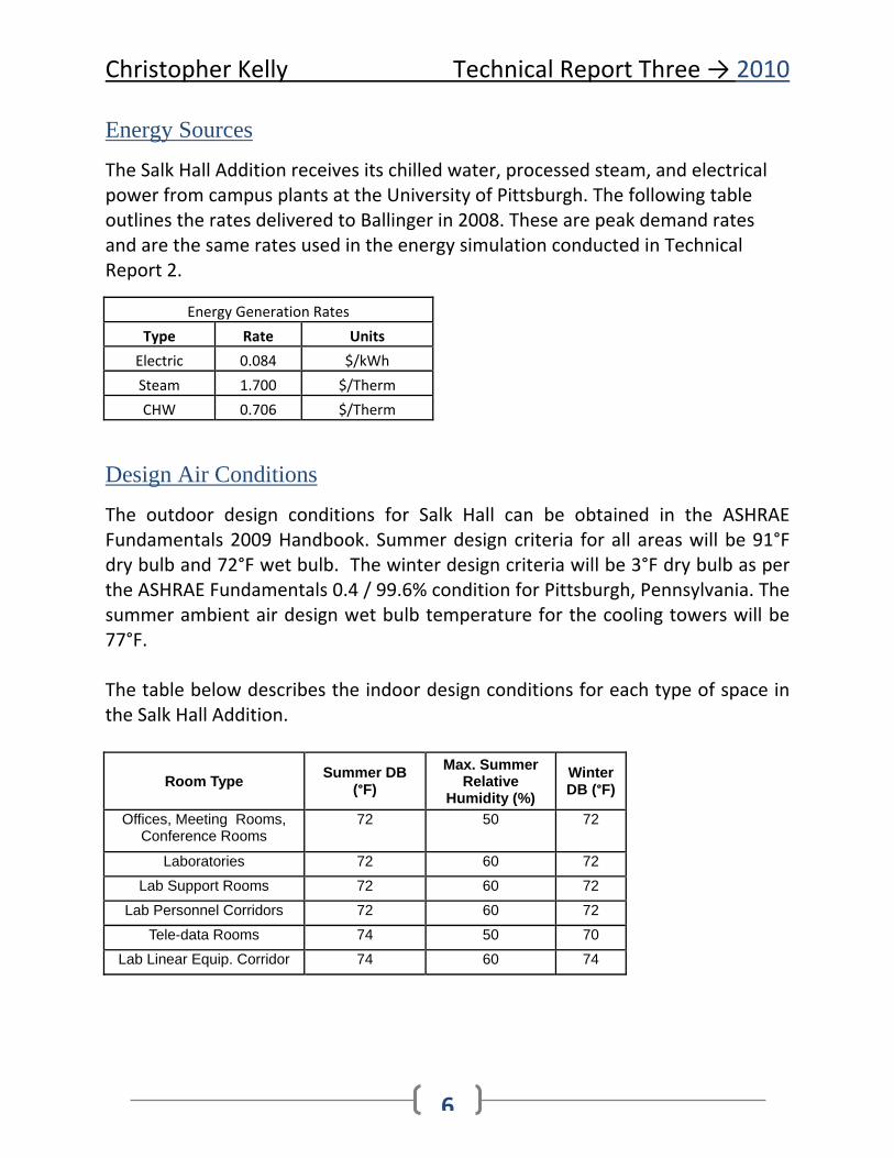
Energy Sources
The Salk Hall Addition receives its chilled water, processed steam, and electrical power from campus plants at the University of Pittsburgh. The following table outlines the rates delivered to Ballinger in 2008. These are peak demand rates and are the same rates used in the energy simulation conducted in Technical Report 2.
Energy Generation Rates Type Rate Units Electric 0.084 $/kWh Steam 1.700 $/Therm CHW 0.706 $/Therm
Design Air Conditions
The outdoor design conditions for Salk Hall can be obtained in the ASHRAE Fundamentals 2009 Handbook. Summer design criteria for all areas will be 91°F dry bulb and 72°F wet bulb. The winter design criteria will be 3°F dry bulb as per the ASHRAE Fundamentals 0.4 / 99.6% condition for Pittsburgh, Pennsylvania. The summer ambient air design wet bulb temperature for the cooling towers will be 77°F. The table below describes the indoor design conditions for each type of space in the Salk Hall Addition.
Room Type Summer DB (°F)
Max. Summer Relative
Humidity (%)
Winter DB (°F)
Offices, Meeting Rooms, Conference Rooms
72 50 72
Laboratories 72 60 72
Lab Support Rooms 72 60 72
Lab Personnel Corridors 72 60 72
Tele-data Rooms 74 50 70
Lab Linear Equip. Corridor 74 60 74
Christopher Kelly Technical Report Three → 2010
7
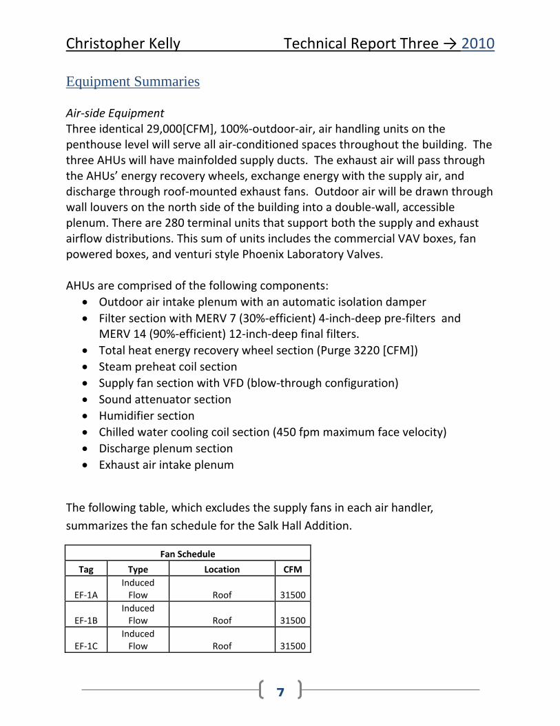
Equipment Summaries Air‐side Equipment Three identical 29,000[CFM], 100%‐outdoor‐air, air handling units on the penthouse level will serve all air‐conditioned spaces throughout the building. The three AHUs will have mainfolded supply ducts. The exhaust air will pass through the AHUs’ energy recovery wheels, exchange energy with the supply air, and discharge through roof‐mounted exhaust fans. Outdoor air will be drawn through wall louvers on the north side of the building into a double‐wall, accessible plenum. There are 280 terminal units that support both the supply and exhaust airflow distributions. This sum of units includes the commercial VAV boxes, fan powered boxes, and venturi style Phoenix Laboratory Valves. AHUs are comprised of the following components:
• Outdoor air intake plenum with an automatic isolation damper • Filter section with MERV 7 (30%‐efficient) 4‐inch‐deep pre‐filters and
MERV 14 (90%‐efficient) 12‐inch‐deep final filters. • Total heat energy recovery wheel section (Purge 3220 [CFM]) • Steam preheat coil section • Supply fan section with VFD (blow‐through configuration) • Sound attenuator section • Humidifier section • Chilled water cooling coil section (450 fpm maximum face velocity) • Discharge plenum section • Exhaust air intake plenum
The following table, which excludes the supply fans in each air handler, summarizes the fan schedule for the Salk Hall Addition.
Fan Schedule Tag Type Location CFM
EF‐1A Induced Flow Roof 31500
EF‐1B Induced Flow Roof 31500
EF‐1C Induced Flow Roof 31500
Christopher Kelly Technical Report Three → 2010
8
EF‐1D Induced Flow Roof 31500
SF‐2 Propeller Main Electric Room 10000EF‐2 Propeller Main Electric Room 10000SF‐3 SWSI Mechanical Level 10000EF‐4 Centrifugal 3rd Floor Roof 3000 EF‐5 Propeller Generator Room 3500 EF‐6 Centrifugal Roof 535 EF‐7 Centrifugal Roof 300
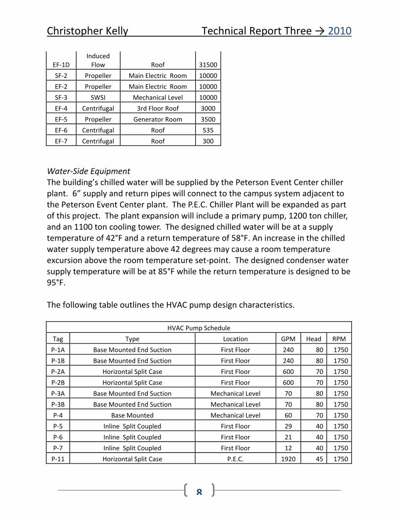
Water‐Side Equipment The building’s chilled water will be supplied by the Peterson Event Center chiller plant. 6” supply and return pipes will connect to the campus system adjacent to the Peterson Event Center plant. The P.E.C. Chiller Plant will be expanded as part of this project. The plant expansion will include a primary pump, 1200 ton chiller, and an 1100 ton cooling tower. The designed chilled water will be at a supply temperature of 42°F and a return temperature of 58°F. An increase in the chilled water supply temperature above 42 degrees may cause a room temperature excursion above the room temperature set‐point. The designed condenser water supply temperature will be at 85°F while the return temperature is designed to be 95°F. The following table outlines the HVAC pump design characteristics.
HVAC Pump Schedule Tag Type Location GPM Head RPM P‐1A Base Mounted End Suction First Floor 240 80 1750P‐1B Base Mounted End Suction First Floor 240 80 1750P‐2A Horizontal Split Case First Floor 600 70 1750P‐2B Horizontal Split Case First Floor 600 70 1750P‐3A Base Mounted End Suction Mechanical Level 70 80 1750P‐3B Base Mounted End Suction Mechanical Level 70 80 1750P‐4 Base Mounted Mechanical Level 60 70 1750P‐5 Inline Split Coupled First Floor 29 40 1750P‐6 Inline Split Coupled First Floor 21 40 1750P‐7 Inline Split Coupled First Floor 12 40 1750P‐11 Horizontal Split Case P.E.C. 1920 45 1750

Christopher Kelly Technical Report Three → 2010
9
The Peterson Event Center houses both the cooling tower and water‐cooled chiller associated with the Salk Hall addition. The cooling tower is of an induced draft design and processes 3000 [GPM]. The design entering water temperature is 90.6 degrees Fahrenheit and the design leaving temperature is 80.6 degrees Fahrenheit. The centrifugal chiller has a capacity of 1200 tons and uses R‐123 as its refrigerant.
Christ
Schem
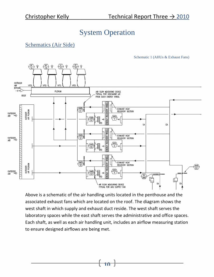
Above iassociatwest shlaboratoEach shto ensu
opher K
matics (Air
s a schemated exhausaft in whicory spacesaft, as welre designe
elly
Sr Side)
atic of the st fans which supply as while the ll as each aed airflows
System
air handlinich are locaand exhauseast shaft
air handling are being
Tech
10
m Opera
ng units located on thst duct rest serves theg unit, inclmet.
hnical Re
ation
Sche
cated in the roof. Theide. The we administudes an ai
eport Thr
ematic 1 (AHU
he penthoue diagram
west shaft strative andirflow mea
ree → 20
Us & Exhaust
use and thshows theserves the d office spaasuring stat
010
Fans)
e e
aces. tion

Christ
Air-SideThe laboair valveairflow provideservice Phoenixbe utilizpositionairflow.more cooverridd
Schem
opher K
e Control Soratory aires with Auand laboraed with airfto maintaix Controls zed to suppned to mai The supplooling. Phoden in case
matics (Ch
elly
Strategy rflow contrtomated Latory tempflow feedbin a constaVAV supplply 100% ontain airfloly valves woenix Conte of an em
hilled Wat
rol system Logic BAS Dperature coback cards,ant face vey air valveoutdoor maow based owill be overrols’ VAV g
mergency.
ter Side)
Tech
11
will be baDDC controontrol. Pho will be utilocity acro, providedakeup air ton total exrridden to ogeneral ex
S
hnical Re
sed on Phoollers perfooenix Contilized for fuoss the fumd with airfloto the laboxhaust flowopen furthhaust valv
Schematic 2
eport Thr
oenix Contorming thetrols CAV aume hood me hood opow feedbaoratory, anw minus thher upon aes can also
(Campus Ch
ree → 20
trols’ Analoe laboratorair valves, exhaust pening. ack cards, wnd will be e room off need for o be
hilled Water L
010
og ry
will
fset
Loop)
Christ
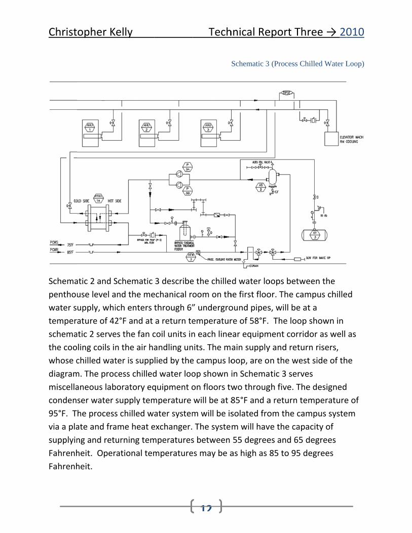
Schemapenthouwater stemperschemathe coowhose cdiagrammiscellaconden95°F. Tvia a plasupplyinFahrenhFahrenh
opher K
atic 2 and Suse level aupply, whiature of 42atic 2 serveling coils inchilled watm. The procaneous labser water he processate and frang and retuheit. Operheit.
elly
Schematic nd the meich enters 2°F and at es the fan cn the air hater is suppcess chilledboratory eqsupply tems chilled wame heat eurning temrational tem
3 describeechanical rothrough 6”a return tecoil units inandling unlied by thed water looquipment omperature ater systemexchanger.mperaturesmperature
Tech
12
e the chilleoom on th” undergroemperaturn each linenits. The me campus loop shown ion floors twwill be at 8m will be is The systes between es may be a
hnical Re
Schematic 3
d water lohe first flooound pipesre of 58°F. ear equipmain supplyoop, are oin Schemawo throug85°F and asolated from will hav55 degreeas high as 8
eport Thr
(Process Ch
oops betweor. The cams, will be at The loop
ment corridy and return the westtic 3 servegh five. Thea return teom the camve the capaes and 65 d85 to 95 d
ree → 20
hilled Water L
een the mpus chillet a shown in dor as welln risers, t side of thes e designedmperaturempus systeacity of degrees egrees
010
Loop)
ed
as
he
e of em

Christopher Kelly Technical Report Three → 2010
13
Chilled Water Control Strategies For multi‐bank coil arrangements, each coil will be furnished with an isolation valve, a P/T plug on the supply side of each coil, a balancing valve, and a P/T plug and isolation valve on the return side of each coil. The supply side of the coil bank will have an isolation valve, strainer with differential pressure gage, thermometer, pressure gage, vents, and drains. The return side of the coil bank will have a pressure gage, thermometer, modulating two‐way control valve, isolation valve, vents and drains.
Two‐way control valves will modulate flow of chilled water through the cooling coils to maintain leaving air temperature set points. Separate leaving air temperature transmitters, in the air handling unit discharges, will be provided for controlling the pre‐heat and chilled water coils. A low‐limit temperature sensor across the upstream face of the chilled water coil will be provided to de‐energize the supply fan in the event of frigid air temperatures, in order to minimize the probability of the chilled water coil freezing. When the low‐limit temperature sensor alarms and alerts the Building Automation System, the chilled water coil control valve will be driven open.
Schematics & Control Strategy (Hot Water Side)
The hot water heating system will consist of two shell‐and‐tube LPS‐to‐hot water heat exchangers. Each heat exchanger will be sized for 100% of the load. Two primary system pumps will be provided, each with a variable‐frequency drive and each sized for 100% of load. VFDs will maintain the differential pressure set point in the system. One or both pumps may operate to meet capacity for optimum energy use. Multiple secondary loops will be provided for the perimeter radiation. Each loop will consist of a 3 way mixing valve and hot water circulator pumps. This system will be constant volume.
Reheat coils and other heating equipment will be provided with modulating two‐way control valves located on the return side of each coil. Terminal reheat valves will modulate to maintain the room temperature set‐point.

Christ
Schema6” camplow predistributheir suand humheaterslocated
opher K
atic 4 detaipus line, is ssure condted to the pport spacmidifiers. L, domesticin the first
elly
ls the procreduced indensates asterilizers ces. The loLow pressuc hot watert floor mec
cess in whinto mediure also proand glass w pressureure steam ir heater, anchanical sp
Tech
14
Schem
ich high prm and lowoduced. Thcleaning ee condensais deliverednd the shepace.
hnical Re
matic 4 (Steam
ressure stew pressure he mediumequipment ate is delivd to the labell and tube
eport Thr
m Pressure R
am, delivesteam. M
m pressure in the labovered to thboratory he heat exch
ree → 20
Reducing Stat
ered from tedium andstream is oratories ahe heating hot water hangers
010
tions)
the d
and coils
Christopher Kelly Technical Report Three → 2010
15
Data Found in Previous Technical Reports Previous Technical Reports covered the information required for this report. The repeat areas include ASHRAE Standard 62.1, ASHRAE Standard 90.1, and TRANE Trace simulation data.
Ventilation Requirements
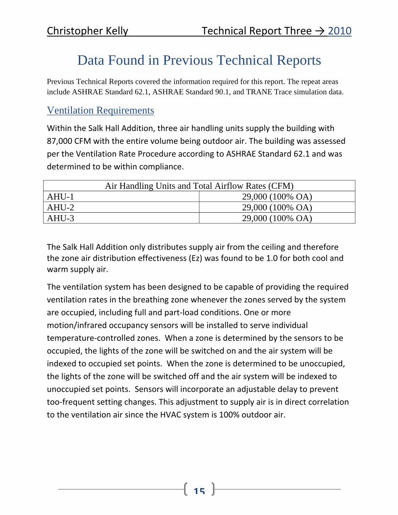
Within the Salk Hall Addition, three air handling units supply the building with 87,000 CFM with the entire volume being outdoor air. The building was assessed per the Ventilation Rate Procedure according to ASHRAE Standard 62.1 and was determined to be within compliance.
Air Handling Units and Total Airflow Rates (CFM) AHU-1 29,000 (100% OA) AHU-2 29,000 (100% OA) AHU-3 29,000 (100% OA)
The Salk Hall Addition only distributes supply air from the ceiling and therefore the zone air distribution effectiveness (Ez) was found to be 1.0 for both cool and warm supply air.
The ventilation system has been designed to be capable of providing the required ventilation rates in the breathing zone whenever the zones served by the system are occupied, including full and part‐load conditions. One or more motion/infrared occupancy sensors will be installed to serve individual temperature‐controlled zones. When a zone is determined by the sensors to be occupied, the lights of the zone will be switched on and the air system will be indexed to occupied set points. When the zone is determined to be unoccupied, the lights of the zone will be switched off and the air system will be indexed to unoccupied set points. Sensors will incorporate an adjustable delay to prevent too‐frequent setting changes. This adjustment to supply air is in direct correlation to the ventilation air since the HVAC system is 100% outdoor air.
Christopher Kelly Technical Report Three → 2010
16
The ventilation system designed for the Salk Hall Addition is also in compliance with the University of Pittsburgh’s laboratory design standard of 6 air changes per hour in laboratories and their associated spaces.
Thermal Loads and Energy Use Per TRACE 700
The TRACE 700 outputs state that Salk Hall will demand 4,260,888 [kWh] at a cost of $357,915 per year. The largest demand on the electrical system, relative to the mechanical systems, is the energy required for fan operation. The ventilation requirement of Salk Hall’s laboratories and their support spaces is the key factor which influences the high fan power demand. In the model, the supply fan delivers 86,000 [CFM] while the exhaust fans pull 91,754 CFM. The design for the Salk Hall Addition allows for 87,000 [CFM] of outdoor supply air.
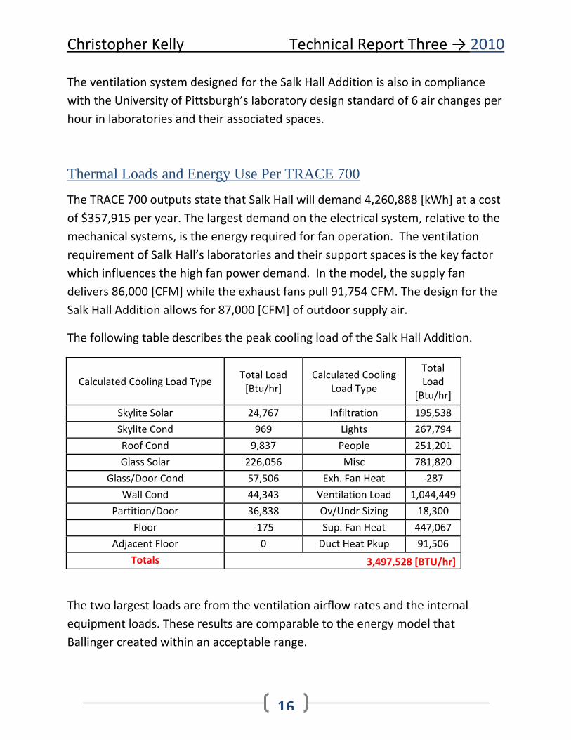
The following table describes the peak cooling load of the Salk Hall Addition.
Calculated Cooling Load Type Total Load [Btu/hr]
Calculated Cooling Load Type
Total Load
[Btu/hr] Skylite Solar 24,767 Infiltration 195,538 Skylite Cond 969 Lights 267,794 Roof Cond 9,837 People 251,201 Glass Solar 226,056 Misc 781,820
Glass/Door Cond 57,506 Exh. Fan Heat ‐287 Wall Cond 44,343 Ventilation Load 1,044,449
Partition/Door 36,838 Ov/Undr Sizing 18,300 Floor ‐175 Sup. Fan Heat 447,067
Adjacent Floor 0 Duct Heat Pkup 91,506 Totals 3,497,528 [BTU/hr]
The two largest loads are from the ventilation airflow rates and the internal equipment loads. These results are comparable to the energy model that Ballinger created within an acceptable range.

Christopher Kelly Technical Report Three → 2010
17
The following table is a breakdown of energy consumption by each respective piece of heating or cooling equipment. The heating energy requirement is much less than the cooling requirement. This is due to the high internal loads.
System
Elect Cons. (kWh)
PCldW Cons. (kBtu)
P.Stm Cons. (kBtu)
Total Building Energy (kBtu/yr)
Primary heating Primary heating 70,055 70,055
Other Htg Accessories 691 2,360 Primary cooling
Cooling Compressor 128,897 128,897 Auxiliary
Supply Fans 2,126,627 7,258,176 Pumps 14,400 49,147
Lighting Lighting 514,005 1,754,300
Receptacle Receptacles 1,604,740 5,476,976
Totals 4,260,463 128,897 70,055 14,739,912
Purchased chilled water for the Salk Hall Addition is estimated to cost the University under $1000 dollars per year. The amount of purchased steam required is under $1200 per year. These two values are relatively low due to the fact that both utilities are delivered from central plants on campus.
It is important to keep in mind that the building is under construction, therefore no actual demand values can be referenced, and the actual cooling demand may vary from the TRACE simulation outputs. The ASHRAE RSTM spreadsheet was used to model the northwest laboratory after Ballinger found discrepancies in the TRACE 700 results. The results were as follows:

Christopher Kelly Technical Report Three → 2010
18
Loads TRACE OUTPUT
RSTM OUTPUT % Difference (Trace to RSTM)
Glass Solar 13,505 Btu/h 9,358 Btu/h 44 % Larger Wall/Window Conduction
5,374 Btu/h 3,555.6 Btu/h 51 % Larger
Infiltration 8,771 Btu/h 7,689.4 Btu/h 14 % LargerLights 14,786 Btu/h 15,192.9 Btu/h 3 % SmallerPeople 9,468 Btu/h 4853.7 Btu/h 95% LargerMisc 63,509 Btu/h 61,670 Btu/h 2.9 % Larger
The RSTM outputs are significantly lower than the TRACE 700 outputs and this example can be used to show that the energy demand on any given building will most likely fall between a range of values.

Christopher Kelly Technical Report Three → 2010
19
LEED Analysis for Mechanical Systems
The Salk Hall addition plans to apply for LEED certification after the construction process is significantly underway. There are two main categories under LEED for assessing the building’s mechanical systems. They are Energy and Atmosphere and Indoor Environmental Quality. The Salk Hall addition will have to submit to the criteria established by LEED 3.0, in which there are 3 prerequisites for Energy and Atmosphere and 2 prerequisites for Indoor Environmental Quality. These prerequisites are mandatory benchmarks for sustainable design.
Energy and Atmosphere
EA Prerequisite 1 is to have fundamental commissioning of the building systems after construction has been completed. Since construction is in its early phases, the Salk Hall Addition cannot fulfill this requirement yet. EA Prerequisite 2 is a design phase prerequisite that states the building has to meet the minimum energy performance which is outlined in EA Credit 1. EA Prerequisite 3 is also a design phase prerequisite in which no CFC based refrigerants are to be used in the designed cooling equipment.
EA Credit 1 evaluates energy performance. This credit cannot be evaluated until a suitable baseline energy model is created for a comparison to the proposed design.
EA Credit 2 requires on‐site renewable energy. The Salk Hall Addition does not utilize renewable energy and therefore cannot receive any points for this credit.
EA Credit 3 deals with enhanced commissioning and is worth 2 points. Again, the Salk Hall Addition is in its early construction phases.
EA Credit 4 is enhanced refrigeration managements. The total refrigerant impact per ton must be less than 100.

Christopher Kelly Technical Report Three → 2010
20
EA Credit 5 is measurement and verification. If points are needed after construction is completed, measurement and verification of energy consumption can be done for an extra three points.
EA Credit 6 deals with buying green power from a utilities provider. The Salk Hall addition receives its utilities from the University of Pittsburgh’s central plants and therefore will not receive points for this credit.
Indoor Environmental Quality
EQ Prerequisite 1 requires ASHRAE Standard 62.1 to be met for indoor air quality. Based on the calculations of Technical Report 2, the Salk Hall Addition will meet these criteria. It is important to keep in mind that the University of Pittsburgh has its own standard for acceptable air quality in laboratories and their support spaces. The rate of 6 air changes per hour in these respective spaces has also been met.
EQ Prerequisite 2 deals with environmental tobacco smoke control. The Salk Hall Addition is a non‐smoking building.
EQ Credit 1 deals with the monitoring of outdoor air delivered to the conditioned spaces. The credit requires that C02 monitoring must be done in every densely occupied space. This credit will not be met by the current design of the Salk Hall Addition.
EQ Credit 2 is increased ventilation. The Salk Hall addition will most likely meet this requirement due to the high air change rates established by the University standard. While the addition will gain points in this category, the increased fan power will hurt the proposed case when it is compared to the baseline model required for EA Credit 1.
EQ Credit 6.2 requires individual comfort control for 50% of the buildings occupants including multi‐occupant spaces. This credit is met because each thermal zone is controlled by a thermostat and its own terminal VAV unit.

Christopher Kelly Technical Report Three → 2010
21
EQ Credit 7.1 deals with the thermal comfort of the occupants. ASHRAE Standard 55‐2004 is satisfied within the Salk Hall design.
EQ Credit 7.2 is the verification of thermal comfort. This credit cannot be gained until a post‐occupancy study is performed.
Overall Evaluation Overall the mechanical system of the Salk Hall addition is well designed. Laboratories often pose a greater design challenge than other buildings due to the large variation in internal loads as well as their high ventilation requirements. In order to maximize efficiency, a variable air volume system has been implemented. This system is capable of supplying the required ventilation air under full and part load conditions, as well to provide make‐up ventilation air when fume hoods or biological safety cabinets are active.
The estimated construction cost of the mechanical system is around 11% of the total cost. This is within an appropriate range since laboratories often require a large amount of lab equipment and its associated architectural casework. Since the Salk Hall Addition receives its utilities from campus plants, the most expensive pieces of mechanical equipment are the air handling units. Variable air volume systems are conventional and easy to install and operate.
The operating cost of the building is dominated by the ventilation requirement of the laboratories. Due to the fact that the laboratories require 6 air changes per hour, the supply fans’ have a high electrical demand. Lab equipment also drives the building’s operation costs up. The myriad of lab equipment associated with the respective spaces can often demand up to 6‐8 watts per square foot per hour. In total, the associated cost of operating the building is roughly $4.30 per square foot. This is within an acceptable range, based on the operation cost rates of other buildings on campus, of the $4.40 per square foot value.

Christopher Kelly Technical Report Three → 2010
22
The Salk Hall Addition demands a large amount of hot water for the reheat coils in the terminal supply units. If the mechanical system utilized waste hot water, it could be distributed to the terminal reheat coils which would ultimate yield an increase in energy savings.
One design issue that the Salk Hall Addition may run across is a lack of added capacity in case of future expansion or a change in the building program. The system currently provides an added 1000 [CFM] to the peak simulated demand. This simulated demand does not include duct losses and this fact could become problematic if extra fume hoods or biological safety cabinets are added to the building’s program.