technical research on evaporative air conditioners … · technical research on evaporative air...
TRANSCRIPT
TECHNICAL RESEARCH ON EVAPORATIVE AIR CONDITIONERS AND FEASIBILITY OF RATING THEIR ENERGY PERFORMANCE
Prepared for SA Department of Transport Energy
and Infrastructure
On behalf of the E3 Committee
Dept of the Environment, Water,
Heritage and Arts
Prepared by Professor Wasim Saman
Dr. Frank Bruno
Mr. Steven Tay
Date of issue March 2010

1
2
Contents
Executive Summary ........................................................................................................ 4
1. Product Profile ............................................................................................................. 6
1.1 Types of evaporative air conditioners ..................... 6
1.2 Suitability for use in Australia ................... 11
1.3 Market share of evaporative air conditioners ................... 14
1.4 Types of heating systems ................... 15
1.4.1 Reverse Cycle Air Conditioners ................................................................ 15
1.4.2 Ground Coupled System ............................................................................. 17
1.4.3 Gas Heating ...................................................................................................... 17
1.4.4 Wood Heating .................................................................................................. 18
1.4.5 Solar Heating ................................................................................................... 20
1.4.6 Hydronic Heating ............................................................................................ 20
1.5 Energy consumption of evaporative air conditioners ................... 21
1.5.1 Cooling effects and energy used .............................................................. 21
1.5.2 Estimates of energy consumption of cooling capacity of energy consumption in different parts of Australia ..................................................... 22
1.6 Energy consumption of the components of evaporative air conditioners ................... 25
2. Regulatory Approaches ....................................................................................... 26
2.1 Australian standards ................... 26
2.2 International regulations and standards ................... 26
2.3 Standard test conditions …………….. 29
2.4 Shortcomings of current standards ………………………. 29
3. Testing/Rating Method ....................................................................................... 30
3.1 Review of available energy consumption testing procedure/methodology ................... 30
3.2 Development of a test methodology ................... 30
3.3 Proposed test conditions ................... 32
3.4 Proposed parameter for rating energy performance ................... 32
3.5 Application of the proposed testing and rating procedures to new technologies ................... 33
4. Performance Evaluation Information ......................................................... 34
4.1 Development of information for rating/labelling ................... 34
4.2 Proposed information for rating/labelling ................... 34
4.3 A parameter for rating the energy performance of evaporative air conditioners ................... 35
3
4.4 Example of the calculation of SEER ................... 36
4.5 Procedure for evaluation of the rating of the energy, cooling
capacity and comfort performance parameters ................... 36
5. Conclusions and recommendations ............................................................. 38
References .............................................................................................................................. 39
Appendix 1: Available Evaporative Air Conditioners in Australia & Their Key
Specifications ........................................................................................................................ 40
Appendix 2: Raw Air Conditioner Data in Figs 6 & 7 (ABS data)............................... 47
Appendix 3: Energy Consumption in a Typical Adelaide Hot Day ........................... 49
Appendix 4: Energy Consumption in a Typical Adelaide Summer Day ................... 51
Appendix 5: Industry Contact List .................................................................................... 53
Appendix 6: Glossary of terms ........................................................................................... 54
4
Executive Summary The installation of mechanical air conditioning appliances has become a normal requirement
in almost all new and existing Australian dwellings. While the use of refrigerated air
conditioners have been rapidly increasing, the market share of evaporative air conditioners
has witnessed a steady decline and currently makes up less than 20% of the installed systems
in Australian dwellings. Domestic air conditioning has considerable impact on energy use and
peak power demand. Evaporative air conditioners generally consume less energy but require
water for their operation.
This report will build on the information provided by a previously completed initial report by
the authors (Saman and Bruno, 2008). The report was discussed by industry Commonwealth
and State Government representatives in a workshop held on June, 2008. The proposed work
takes into consideration feedback received from the workshop participants and aims to
implement some of the recommendations put forward by the report and agreed upon by the
workshop participants.
In developing a draft methodology for rating the energy performance of evaporative coolers,
it has been proposed previously that the process should be carried out alongside a parallel
process being instigated for rating the water consumption of evaporative coolers and
incorporating them in the Water Efficiency Labelling Scheme (WELS). The development of a
combined procedure for rating both energy and water consumption has been recommended in
a report recently submitted by the authors (Saman, Bruno and Liu, 2009). This report
incorporates and updates some of the information gathered in the previous reports on the size
and features on the evaporative air conditioning market.
The report includes available information on energy consumption of evaporative air
conditioners and calculations of typical energy consumption and performance of evaporative
air conditioners in different Australian locations. The results highlight the suitability of using
evaporative air conditioners in most Australian locations except in the hot humid regions. The
report also demonstrates the sensitivity of the cooling capacity and energy consumption to the
air moisture content.
This report also reviews currently available local and international regulations and standards
for testing, labelling and rating evaporative air conditioners. The California Appliance
Efficiency Regulations include a procedure for evaluating and rating the energy performance
of evaporative air conditioners. Iran is the only country that currently conducts a mandatory
comparative labelling program for energy consumption of evaporative air conditioners. A
proposed test and evaluation methodology for rating energy performance is put forward. It is
proposed that independent testing should be carried out alongside water consumption testing
using a single test facility. The report sets out a detailed proposed procedure for carrying out
standard testing of evaporative air conditioners to evaluate their energy consumption
characteristics. The proposed testing procedure supplements the current Australian Standards
AS/NZS 2913-2000.
The report proposes the use of a new location specific ―Seasonal Energy Efficiency Ratio‖ as
the key parameter for evaluating the energy performance of evaporative air conditioners. This
parameter can be evaluated through calculations based on the standard test results and the
annual temperature and humidity variations for a typical year. Based on the test and
calculation results, it also proposes the evaluation of a number of other parameters which will
5
characterize comfort provision, cooling capacity energy use and cost for tested systems. These
parameters will provide useful information to consumers, manufacturers/suppliers and
governments. As the performance of evaporative air conditioners, is dependant on local
temperature and humidity patterns, these parameters can be evaluated by computer modeling
for all main Australian locations. An interactive computational tool has been developed to
evaluate the key cooling capacity, comfort and energy consumption parameters for major
cities in Australia with the input data being the results of the proposed testing methodology.
Early consultation with manufacturers, suppliers and users groups is considered to be an
important step in progressing a labelling/rating system for energy and water use in
evaporative air conditioners. A technical study for further developing a standard test
procedure, testing facilities and methodology for independent testing, rating/labelling of both
water and energy use in evaporative air conditioners, as well as modifying the current test
standard to provide for this, is also recommended.
6
1. Product Profile
1.1 Types of evaporative air conditioners
The utilisation of water evaporation for cooling purposes has its origins well entrenched in
history. Evidence of evaporative cooling applications by ancient people of the Middle East is
widely documented and some of these applications are still in use in the Middle East today.
They include the use of porous water vessels, the wetting of pads made of dried vegetables
which cover the doors and windows facing the prevailing wind and directing the prevailing
wind into pools of running water in underground rooms (Saman, 1993). Early Australians also
used different forms of evaporative air cooling to obtain some comfort in the hot dry climates
of outback Australia.
Direct evaporative air conditioning is ideal for arid climates where water is available. The
direct evaporative air conditioners currently produced have, by and large, overcome the
drawbacks associated with older systems. In addition to more efficient fan and duct designs
and control systems, the use of plastics for the bodywork, cellulose and other synthetic
materials for the pads together with automatic water bleeding or flushing has resulted in more
reliable operation with little maintenance. Many of today‘s evaporative air conditioners have
quite sophisticated control systems with variable air speeds and pad wetting rates. The one
remaining inherent drawback associated with direct cooling is the water saturation limit
inherent in the process. Even with saturation efficiency over 80%, which is common for
many modern systems, the air supplied may not provide cooling comfort if the outside air
temperature is high and/or its moisture content is high and close to saturation with water
vapour. The lowest possible temperature limit attained by direct evaporative cooling is the
wet bulb temperature at which the delivered air is fully saturated with moisture.
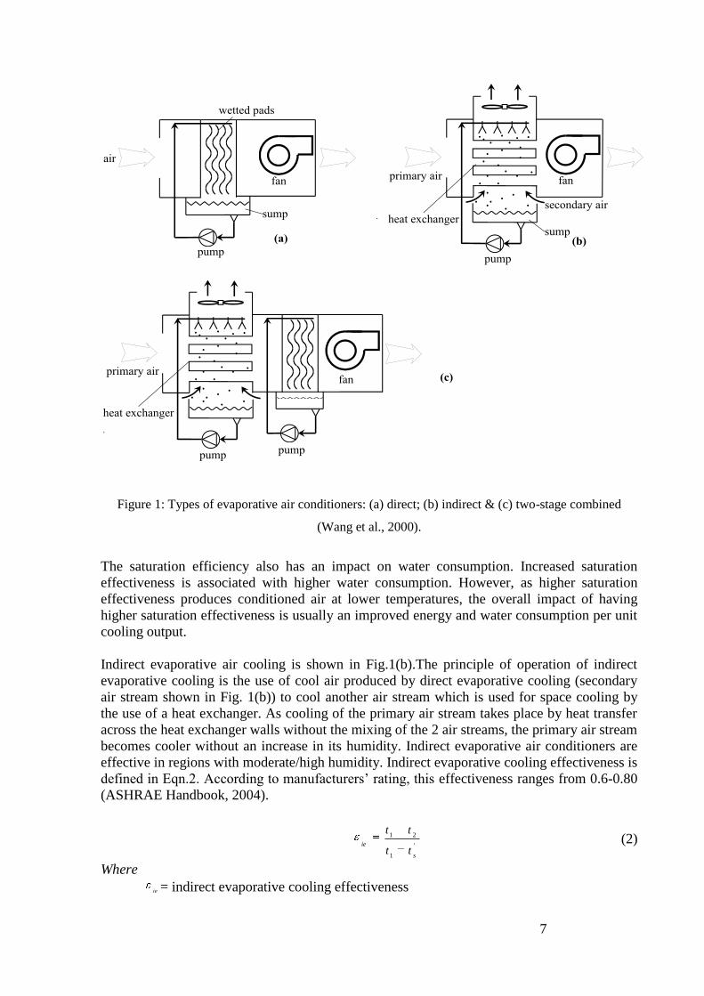
Evaporative air conditioners can be categorised as direct, indirect, two- and multi-stage.
Direct evaporative air conditioners are the most popular in the market. As shown in Fig.1 (a),
outside air is drawn through wetted filter pads, where the hot dry air is cooled and humidified
through water evaporation. The evaporation of water takes some heat away from the air
making it cooler and more humid. The dry-bulb temperature of the air leaving the wetted pads
approaches the wet-bulb temperature of the ambient air. Direct evaporative air conditioners
are more effective in dry climates. As they produce warmer, more humid air in comparison
with refrigerated air conditioners, considerably more air volumes are required to produce the
same cooling effect. The cool/humid air is used once and cannot be reused. Evaporation
(saturation) effectiveness is the key factor in determining the performance of evaporative air
conditioners. It is defined by Eqn.1. This property determines how close the air being
conditioned is to the state of saturation. Usually, the efficiency is 85-95% (ASHRAE
Handbook, 2007).
'tt
tte
1
21
100 (1)
Where
e = direct evaporation (saturation) efficiency, %
1t = dry-bulb temperature of entering air, oC
2t = dry-bulb temperature of leaving air, oC
't = wet-bulb temperature of entering air, oC
7
FAN
FAN
FAN
Figure 1: Types of evaporative air conditioners: (a) direct; (b) indirect & (c) two-stage combined
(Wang et al., 2000).
The saturation efficiency also has an impact on water consumption. Increased saturation
effectiveness is associated with higher water consumption. However, as higher saturation
effectiveness produces conditioned air at lower temperatures, the overall impact of having
higher saturation effectiveness is usually an improved energy and water consumption per unit
cooling output.
Indirect evaporative air cooling is shown in Fig.1(b).The principle of operation of indirect
evaporative cooling is the use of cool air produced by direct evaporative cooling (secondary
air stream shown in Fig. 1(b)) to cool another air stream which is used for space cooling by
the use of a heat exchanger. As cooling of the primary air stream takes place by heat transfer
across the heat exchanger walls without the mixing of the 2 air streams, the primary air stream
becomes cooler without an increase in its humidity. Indirect evaporative air conditioners are
effective in regions with moderate/high humidity. Indirect evaporative cooling effectiveness is
defined in Eqn.2. According to manufacturers‘ rating, this effectiveness ranges from 0.6-0.80
(ASHRAE Handbook, 2004).
'
1
21
s
ie
tt
tt (2)
Where
ie = indirect evaporative cooling effectiveness
8
1t = dry-bulb temperature of entering primary air, oC
2t = dry-bulb temperature of leaving primary air, oC
'st = wet-bulb temperature of entering secondary air,
oC
Two stage or indirect/direct evaporative air conditioners combine both direct and indirect
evaporative principles. In two-stage evaporative air conditioners, the first stage (indirect)
sensibly cools the primary air (without increasing its moisture content) and the air is
evaporatively cooled further in the second stage (direct) as shown in Fig.1(c). The dry-bulb
temperature of the supplied primary air can be reduced to 6 K or more below the secondary
air wet-bulb temperature (ASHRAE Handbook, 2004) without adding too much moisture. As
two-stage evaporative coolers produce lower temperatures, they consequently require less air
delivery in comparison with the direct systems. Heidarinejad et al. (2009) experimentally
studied the cooling performance of two-stage evaporative cooling systems under the climate
conditions of seven Iranian cities. It has been found that the saturation efficiency (as defined
in equation 1 above) of the indirect/direct evaporative air conditioner varies in a range of
108~111%. Also, over 60% energy can be saved using this system compared to a vapour
compression system. However, it consumes 55% more water in comparison with direct
evaporative cooling system for the same air delivery rate. Monitoring the electricity
consumption of evaporative and conventional refrigerated cooling systems in a small
commercial building has demonstrated considerable energy savings and improved thermal
comfort with evaporative cooling (Saman, et al. 1995). Indirect evaporative cooling can also
be used as a component of multistage air conditioning systems which may also include
refrigerated cooling stages. In such cases, the indirect evaporative cooling may be sufficient
for the provision of typical summer cooling requirements. The refrigerated stage operation is
limited to peak demand days.
Indirect evaporative air conditioners have been gaining more popularity in the market in
recent years. Recently, both Seeley International and Clear Solar have started marketing
indirect evaporative air conditioners. Seeley has been developing such air conditioners for a
number of years. Clear Solar is marketing a product developed in USA by Coolerado.
Both products produce air at conditions closer to refrigerated systems. Unlike conventional air
conditioning units, they use no ozone-depleting chemicals and have mainly one energy-
consuming component, the fan. The heart of both systems which sets them apart from
conventional evaporative coolers is a unique wetting system, a modular heat and mass
exchanger and the way the air flows through it.
In 2008, Coolerado received a grant to build a solar-powered mobile demonstration cooler
which brought Coolerado to the attention of a broader audience. The unit is outfitted with four
PV panels to power the cooler, and the cooler helps the solar array run at a lower temperature
and hence improved efficiency by about 15%.
Seeley has drawn together its most innovative and energy efficient technologies and merged
them with what it has been developing behind the scenes, over the past 14 years. The result is
Climate Wizard, a product that incorporates a patented revolutionary heat exchanger which
ensures that no moisture is added to the air entering the conditioned space, and at the same
time it maximises the effectiveness of all of the elements necessary to best facilitate the heat
exchange process.
9
Climate Wizard delivers significantly colder air than can be achieved by traditional
evaporative cooling. It delivers air at temperatures near, and at times, below, those produced
by refrigerated air conditioning. According to the manufacturer, Climate Wizard uses up to 54%
less energy than a fixed speed refrigerated system. Based on independent testing by the
University of South Australia, Climate Wizard is able to provide pre-cooled ―make-up air‖ to
large commercial refrigeration plants, resulting in energy savings of up to 35%, and at times,
even more. A Slim-line version for domestic applications, designed for installation against the
outer walls of homes, has approximately the same footprint as a water heater. Air is delivered
through the space between the outer wall and the roof into the home and then through a
conventional ducting system in the ceiling space, and into the rooms of homes. Ducting and
fittings are the same dimensions as for traditional refrigerated systems.
The main focus of this report is direct evaporative air conditioners as most units in current use
within Australia are of this variety. However, the scope of the report also includes indirect and
two-stage systems in view of their recent entry into the Australian market.
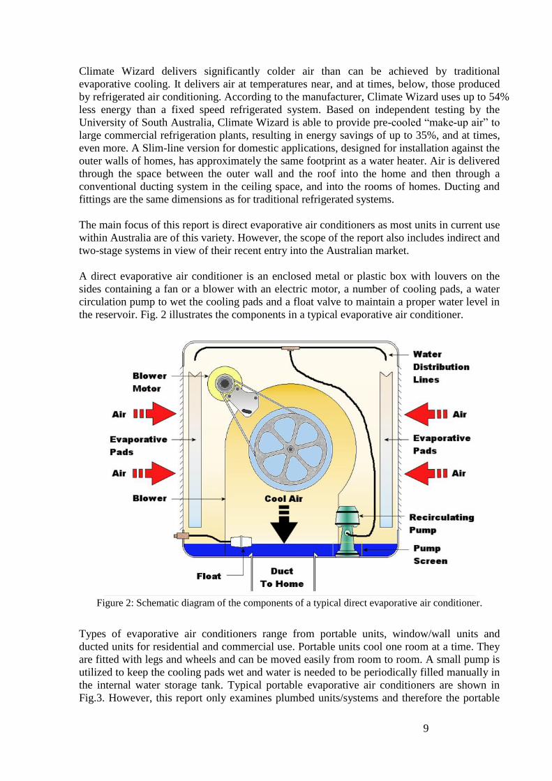
A direct evaporative air conditioner is an enclosed metal or plastic box with louvers on the
sides containing a fan or a blower with an electric motor, a number of cooling pads, a water
circulation pump to wet the cooling pads and a float valve to maintain a proper water level in
the reservoir. Fig. 2 illustrates the components in a typical evaporative air conditioner.
Figure 2: Schematic diagram of the components of a typical direct evaporative air conditioner.
Types of evaporative air conditioners range from portable units, window/wall units and
ducted units for residential and commercial use. Portable units cool one room at a time. They
are fitted with legs and wheels and can be moved easily from room to room. A small pump is
utilized to keep the cooling pads wet and water is needed to be periodically filled manually in
the internal water storage tank. Typical portable evaporative air conditioners are shown in
Fig.3. However, this report only examines plumbed units/systems and therefore the portable

10
units will be excluded from the discussion. Window/wall evaporative air conditioners are
mounted through exterior windows or walls and they can cool larger areas than the portable
units. A window evaporative unit is presented in Fig. 4. Ducted evaporative air conditioners
make up the vast majority in use in Australia. They are usually mounted on the roof and the
cooled air is delivered through ducts to each room in the building. Fig. 5 shows residential
roof ducted evaporative air conditioners with different profiles. Both window/wall and ducted
units have a water bleeding system to control the water salinity under a certain level.
Figure 3: Portable evaporative air conditioners
(http://www.convair.net.au/convairnew/peac/ConvairPEAC.html).

11
Figure 4: (a) Window evaporative air conditioner; (b) View from cooled space; (c) View from outside.
(http://www.bonaire.com.au/evaporativecooling/window/default.aspx)
Figure 5: Residential roof ducted evaporative air conditioners with different profiles.
1.2 Suitability for use in Australia
Using the Australian summer design conditions, Tables 1 and 2 include the estimates of the
performance parameters of direct and indirect evaporative air conditioners. The parameters
include the outlet temperature, relative humidity and cooling capacity for 8 Australian
locations.
(b)
(c)
(a)

12
Table 1: Performance of direct evaporative air conditioners at some Australian locations
AIRAH
Design
Conditions
Air conditioner
Supply Conditions
Cooling Capacity
(kW) Based on
10 000 m3/hr
air flow Dry Bulb
(°C) Wet Bulb
(°C) Dry Bulb
Temperature
(°C)
Relative
Humidity
(%)
Adelaide 37.0 20.1 22.6 46.3 14.9
Brisbane 30.8 22.8 24.0 75.9 10.2
Canberra 34.3 18.1 20.5 43.0 22.2
Darwin 34.4 23.6 25.2 69.3 6.1
Hobart 27.1 16.8 18.4 59.2 29.5
Melbourne 34.3 19.4 21.7 50.0 18.3
Perth 36.6 20.1 22.5 47.5 15.1
Sydney 31.1 19.8 21.5 61.8 18.8
The first two columns of Table 1 show the AIRAH design conditions of the dry and wet bulb
temperatures for eight cities in Australia. The dry bulb temperatures of the air leaving the
direct evaporative air conditioner are presented in the third column. The temperatures of the
air leaving the direct evaporative air conditioner can be calculated from Eqn. 1, based on the
assumption that the saturation efficiency of the direct evaporative air conditioner is 85%. The
relative humidity of the air leaving the evaporative air conditioner is also included in the table.
Based on a nominal volume flow rate of 10,000 m3/hr for the air conditioner, the cooling
capacity of the direct evaporative air conditioner is computed based on Eqn. 3 below. Table 1
shows that despite the relatively low temperatures achieved by direct evaporative air
conditioners, the low cooling capacity and high humidity produced in the tropical and
subtropical regions (Darwin, Brisbane) make their use impractical. However, comfort cooling
conditions (temperature and relative humidity) and high cooling capacities are achievable in
all other Australian locations having relatively cool and/or dry summers.
One option for extending the climatic regions where evaporative cooling is effective is the use
of indirect or 2 stage indirect/direct evaporative cooling. The use of a heat exchanger to cool
the outside air without humidifying it by making use of indirect evaporative cooling systems
was developed in Australia in the 1960s and 1970s; plate heat exchangers were manufactured
and marketed (Pescod, 1968 & Pescod, 1979). From the manufacturing view point, the main
challenge of the system is the size and cost of the heat exchanger required to achieve good
effectiveness and low pressure loss. Work has been done at the University of South Australia
13
to develop low cost heat exchangers optimised for heat recovery as well as indirect
evaporative cooling purposes (Saman & Kilsby, 1999).
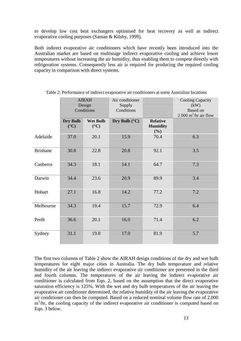
Both indirect evaporative air conditioners which have recently been introduced into the
Australian market are based on multistage indirect evaporative cooling and achieve lower
temperatures without increasing the air humidity, thus enabling them to compete directly with
refrigeration systems. Consequently less air is required for producing the required cooling
capacity in comparison with direct systems.
Table 2: Performance of indirect evaporative air conditioners at some Australian locations
AIRAH
Design
Conditions
Air conditioner
Supply Conditions
Cooling Capacity
(kW) Based on
2 000 m3/hr air flow
Dry Bulb
(°C) Wet Bulb
(°C) Dry Bulb (°C) Relative
Humidity
(%)
Adelaide 37.0 20.1 15.9 70.4 6.3
Brisbane 30.8 22.8 20.8 92.1 3.5
Canberra 34.3 18.1 14.1 64.7 7.3
Darwin 34.4 23.6 20.9 89.9 3.4
Hobart 27.1 16.8 14.2 77.2 7.2
Melbourne 34.3 19.4 15.7 72.9 6.4
Perth 36.6 20.1 16.0 71.4 6.2
Sydney 31.1 19.8 17.0 81.9 5.7
The first two columns of Table 2 show the AIRAH design conditions of the dry and wet bulb
temperatures for eight major cities in Australia. The dry bulb temperature and relative
humidity of the air leaving the indirect evaporative air conditioner are presented in the third
and fourth columns. The temperatures of the air leaving the indirect evaporative air
conditioner is calculated from Eqn. 2, based on the assumption that the direct evaporative
saturation efficiency is 125%. With the wet and dry bulb temperatures of the air leaving the
evaporative air conditioner determined, the relative humidity of the air leaving the evaporative
air conditioner can then be computed. Based on a reduced nominal volume flow rate of 2,000
m3/hr, the cooling capacity of the indirect evaporative air conditioner is computed based on
Eqn. 3 below.
14
1.3 Market share of evaporative air conditioners
There are currently four major local evaporative air conditioner manufacturers: Air Group
Australia Pty Ltd, Carrier Australia Pty Ltd, Climate Technologies Pty Ltd and Seeley
International Pty Ltd. The evaporative air conditioners that are currently available in Australia
together with their key available specifications (such as type, energy input, water bleeding
system, fan and pad type, supply flow rate, control system and evaporation efficiency) are
listed in Appendix 1.
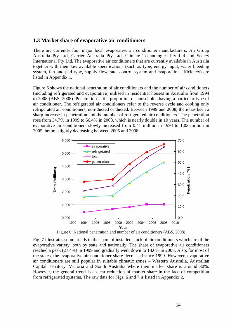
Figure 6 shows the national penetration of air conditioners and the number of air conditioners
(including refrigerated and evaporative) utilised in residential houses in Australia from 1994
to 2008 (ABS, 2008). Penetration is the proportion of households having a particular type of
air conditioner. The refrigerated air conditioners refer to the reverse cycle and cooling only
refrigerated air conditioners, non-ducted or ducted. Between 1999 and 2008, there has been a
sharp increase in penetration and the number of refrigerated air conditioners. The penetration
rose from 34.7% in 1999 to 66.4% in 2008, which is nearly double in 10 years. The number of
evaporative air conditioners slowly increased from 0.41 million in 1994 to 1.03 million in
2005, before slightly decreasing between 2005 and 2008.
Figure 6: National penetration and number of air conditioners (ABS, 2008)
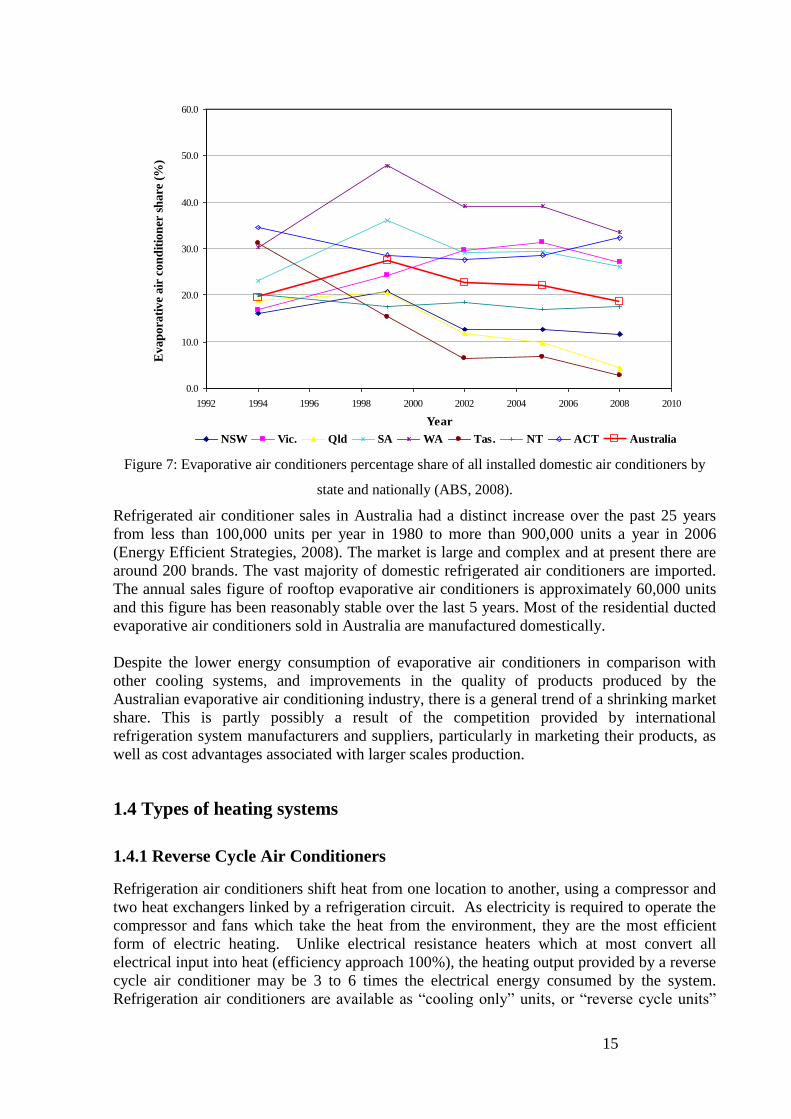
Fig. 7 illustrates some trends in the share of installed stock of air conditioners which are of the
evaporative variety, both by state and nationally. The share of evaporative air conditioners
reached a peak (27.4%) in 1999 and gradually went down to 18.6% in 2008. Also, for most of
the states, the evaporative air conditioner share decreased since 1999. However, evaporative
air conditioners are still popular in suitable climatic zones – Western Australia, Australian
Capital Territory, Victoria and South Australia where their market share is around 30%.
However, the general trend is a clear reduction of market share in the face of competition
from refrigerated systems. The raw data for Figs. 6 and 7 is listed in Appendix 2.
0.000
1.000
2.000
3.000
4.000
5.000
6.000
1992 1994 1996 1998 2000 2002 2004 2006 2008 2010
Year
Un
its
(mil
lio
ns)
0.0
10.0
20.0
30.0
40.0
50.0
60.0
70.0
Pen
etr
ati
on
(%
)
evaporative
refrigerated
total
penetration
15
Figure 7: Evaporative air conditioners percentage share of all installed domestic air conditioners by
state and nationally (ABS, 2008).
Refrigerated air conditioner sales in Australia had a distinct increase over the past 25 years
from less than 100,000 units per year in 1980 to more than 900,000 units a year in 2006
(Energy Efficient Strategies, 2008). The market is large and complex and at present there are
around 200 brands. The vast majority of domestic refrigerated air conditioners are imported.
The annual sales figure of rooftop evaporative air conditioners is approximately 60,000 units
and this figure has been reasonably stable over the last 5 years. Most of the residential ducted
evaporative air conditioners sold in Australia are manufactured domestically.
Despite the lower energy consumption of evaporative air conditioners in comparison with
other cooling systems, and improvements in the quality of products produced by the
Australian evaporative air conditioning industry, there is a general trend of a shrinking market
share. This is partly possibly a result of the competition provided by international
refrigeration system manufacturers and suppliers, particularly in marketing their products, as
well as cost advantages associated with larger scales production.
1.4 Types of heating systems
1.4.1 Reverse Cycle Air Conditioners
Refrigeration air conditioners shift heat from one location to another, using a compressor and
two heat exchangers linked by a refrigeration circuit. As electricity is required to operate the
compressor and fans which take the heat from the environment, they are the most efficient
form of electric heating. Unlike electrical resistance heaters which at most convert all
electrical input into heat (efficiency approach 100%), the heating output provided by a reverse
cycle air conditioner may be 3 to 6 times the electrical energy consumed by the system.
Refrigeration air conditioners are available as ―cooling only‖ units, or ―reverse cycle units‖
0.0
10.0
20.0
30.0
40.0
50.0
60.0
1992 1994 1996 1998 2000 2002 2004 2006 2008 2010
Year
Evap
ora
tive
air
con
dit
ion
er s
hare
(%
)
NSW Vic. Qld SA WA Tas. NT ACT Australia
16
which provide both cooling and energy efficient heating. There are a number of different
types of refrigeration air conditioners available:
window/wall units which are used for individual rooms or small open plan areas.
non-ducted split systems which are used for individual rooms or small open plan areas.
These differ to the above in that the 2 heat exchangers are separated, one being located
indoors and the other outdoors.
ducted systems (usually of the split type) which are used for large open plan areas or the
whole floor of a building.
multi-split systems, which have more than one indoor unit with more than one independent
indoor controls, with only one condenser unit located outside.
chillers which cool water as opposed to air. The cold water is then piped around the home
to cool the air with the use of heat exchangers.
Reverse cycle air conditioners are available as fixed-speed, inverter (variable speed) and
variable capacity (digital scroll).
Inverter (Variable Speed)
Conventional air conditioners have single speed compressors, which run at a constant speed
and vary their capacity by switching on and off at various times guided by the thermostat
setting. Their efficiency stays relatively constant at part load output. A new innovation in air
conditioner technology is the use of an inverter or variable speed drive in the motor system
that drives the compressor. While these systems tend to have lower performance at full load
than conventional air conditioners, they tend to be more efficient at part load operation, which
is a more common mode in a typical household. Air conditioners with a variable output
compressor allow the compressor output to be reduced to match the steady state output
required. They are, however, more expensive to buy. Inverter units are marked on the air
conditioner product listing at www.energyrating.gov.au and part load efficiency data is also
available for some inverter models.
Variable Capacity (Digital Scroll)
Varying the speed of a compressor is one means of varying the capacity of the cooler.
Another technology available to vary the capacity is the digital scroll.
Digital Scroll has two Scrolls which turn against each other around a common axis to
compress the refrigerant gas. The Digital Scroll compressor operates in two stages: the loaded
state and the unloaded state. During the loaded stage, the compressor operates like a standard
scroll and delivers full capacity. During the unloaded stage it does not deliver any capacity.
The continuous alternating of these stages of loaded and unloaded state in a specific period of
time (work cycle) determines the capacity modulation of the compressor.
The inverter technology usually allows the air conditioner to go down to about 40% capacity
whilst a digital scroll compressor can adjust between 10–100% capacity. Unlike an inverter,
the Energy Efficiency Ratio (see definition in section 1.5 below) of a digital scroll does not
improve as the capacity is reduced.
Generally the energy efficiency of refrigeration air conditioners is higher for space heating
compared to when they are used for space cooling.

17
1.4.2 Ground Coupled System
Like refrigeration air conditioners, ground coupled (sometimes referred to as geothermal)
systems are available as ―cooling only‖ types or ―reverse cycle‖.
Ground coupled heat pump systems can be used for residential space heating and cooling.
The ground just below the surface remains at approximately constant temperature all year
round. The underground temperature is greater than the outside air temperature in the winter
months, and less than the outside air temperature in the summer months. The ground source
heat pump can be used to draw the geothermal heat from the ground in the winter and release
the heat back into the ground in the summer.
The three principal components of a ground coupled heat pump system are the heat pump, the
ground connection and the conditioned air distribution system. The heat pump component is
a refrigeration system as used in a refrigeration air conditioner that uses outside air as a heat
sink/source, except it is connected to a ground loop and uses the ground, rather than the air, as
a heat sink/source. The ground connection, or ground loop, is buried underground, adjacent
to the residence to be heated and cooled.
The ground loop can be buried in various configurations. It can consist of loops of plastic
pipe placed vertically into the ground, several metres deep, and back-filled to provide good
ground contact. The loop can be buried horizontally in trenches, either in lengths of pipe or in
coils. The loop could also be placed at the bottom of a pond. A heat transfer fluid (usually
water) is circulated through the ground loop and the heat pump heat exchanger to complete its
ground connection. The heat pump system uses a standard conditioned air distribution system
of ductwork, like that which is used for other standard types of heating and cooling systems.
The relatively constant temperature of the earth enables a ground coupled heat pump system
to operate with a greater efficiency than an equivalent air-to-air system. It is generally
accepted that electrical energy use can be reduced by around 30% with ground coupled heat
pumps, when compared to a refrigerated air conditioner. Note that this comparison is
assuming both systems have fixed-speed compressors. Both of these systems could use an
inverter to increase energy efficiency.
The cost of a typical residential ground coupled heat pump installation, over a comparable air
sink/source system, would be in the range of 50 to 120% greater, depending on which type of
ground connection is used. Pond type ground source heat pumps tend to be the least
expensive of the systems. Although the initial cost is more, the annual savings can make
ground coupled heat pumps well worth the extra expense.
1.4.3 Gas Heating
Space heating systems using natural gas is very common in Australia where reticulated gas is
available. In areas where natural gas is not available, heaters can be run on liquefied
petroleum gas (LPG or ‗bottled‘ gas), although generally this is a significantly more
expensive option. Traditionally, gas heating has been used in dwellings having evaporative air
conditioning.
Victoria has the largest and most extensive gas distribution system and a high heating
requirement hence a high penetration of gas heating. Perth has milder climates but has well
18
established gas networks. Queensland has a very low heating requirement and a very limited
natural gas distribution system.
Gas space heaters consist of two main types; ducted units and non-ducted units.
Ducted units consist of a central heating unit, located either in the ceiling cavity, under the
floor or outside the home. The unit draws air from inside the house, warms it through a heat
exchanger and then pumps the warmed air back into the home through a system of ducts,
located in the ceiling or in the floor, depending on house design. The air for combustion is
drawn from outside and is flued to the outside after combustion so that no combustion
products enter the home. Some systems also allow zoning which gives the user control over
which rooms are heated, to what temperature, during what times of the day or night. Ducted
heating systems are generally more popular in colder climates, due to their large heating
capacity and their ability to heat the whole house. Ducted systems generally have a higher
capital and installation cost. All ducted systems use convection as the means of heating.
Non-ducted units consist of a range of types with differing heating delivery methods and
associated accessories. Non-ducted types can be split into flued and unflued systems. Fluing
systems externally exhaust the heater combustion products to the outside.
Unflued units are those where the gas combustion process takes place wholly within the room
being heated. The air for combustion is drawn from the room and the combustion products are
returned to the room. Typically unflued space heaters tend to be of smaller capacity. Portable
units are generally unflued. Unflued heaters also have nominally a high efficiency as all heat
is returned to the room, but there are requirements for ventilation as the combustion products
(water and carbon dioxide) also enter the room. There are several issues surrounding unflued
units. Each State has differing regulations pertaining to the use of unflued gas space heaters.
In Victoria, unflued heaters may only operate on LPG.
Non ducted units can also be split into three differing heat delivery methods; convection,
radiant and gas log (decorative) and combinations of these. Convection based units warm the
indrawn air and then pump it into the space to be warmed. Radiant units heat panels on the
face of the unit to a high temperature which then directs radiant heat energy towards the user,
who generally has be to in fairly close proximity to get the benefits. Many radiant heaters also
have a fan that moves air around the room as well (generally called radiant/convection
combination units). Gas log units use stylised ceramic logs and realistic flames to create a
traditional wood fire effect. They generally have large glass faces, which allows viewing of
the fire and radiation of some heat; most also have fans that help circulate the warmed air.
Gas space heaters display an Energy Rating Label with 1 to 6 stars. This label identifies the
energy efficiency of the heater—the more stars, the more efficient. Energy efficient units
produce more heat for each unit of gas consumed. High efficiency gas heaters use 90 per cent
of the heat contained in the gas.
1.4.4 Wood Heating
Wood heaters are available in a wide range of models that vary in output from small units
intended to heat a single room, to very large units with the capacity to heat relatively large
houses. The final selection will depend upon a number of factors: e.g. house design, insulation
levels and the length of time the heater is to be operated. Larger heaters are best suited to
homes with an open plan design where heat can be readily and effectively circulated to other
19
areas of the home. Most new wood heaters for sale in Australia are tested to determine their
output, energy efficiency and particle emissions levels under the Australian/New Zealand
Standards AS/NZS4012 and AS/NZS4013.
Wood heaters provide heat in one or a combination of the following ways:
(i) Radiation
(ii) Convection
(iii) Fan forced air distribution
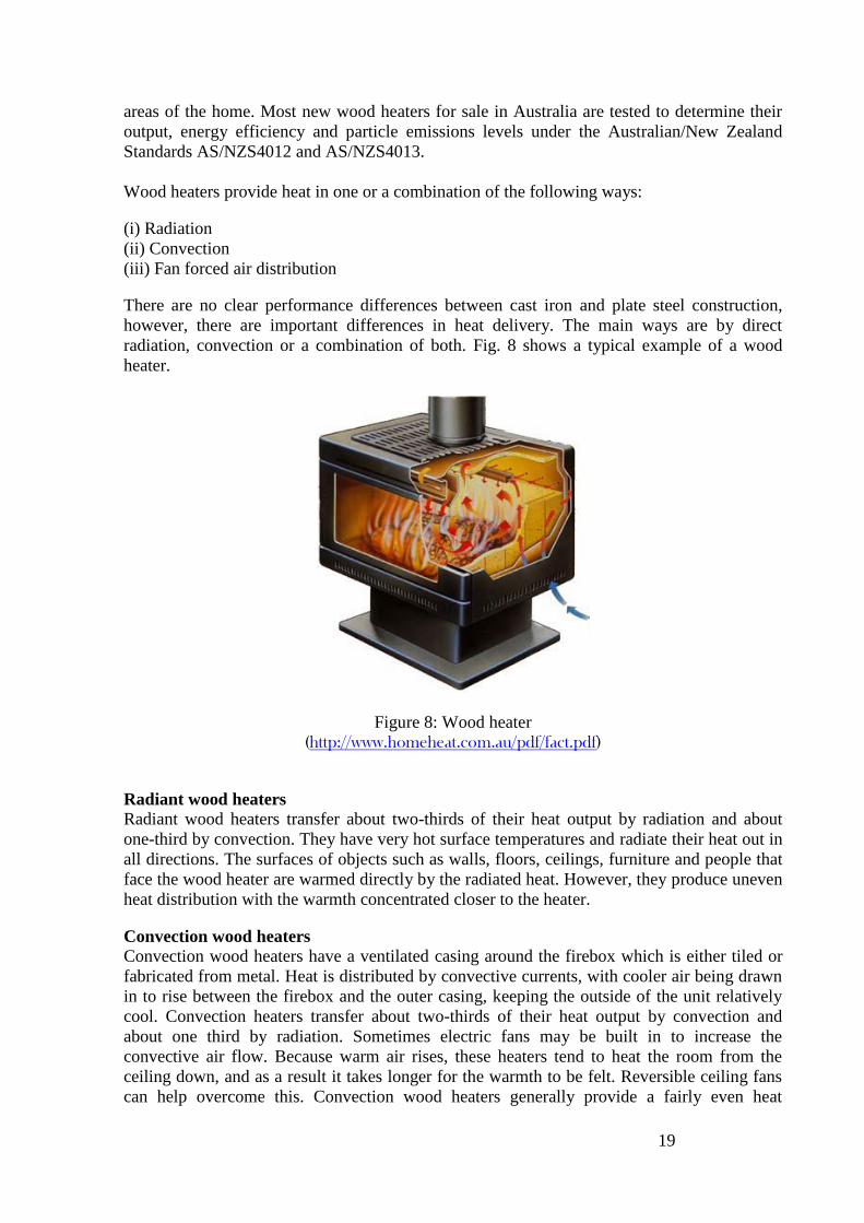
There are no clear performance differences between cast iron and plate steel construction,
however, there are important differences in heat delivery. The main ways are by direct
radiation, convection or a combination of both. Fig. 8 shows a typical example of a wood
heater.
Figure 8: Wood heater (http://www.homeheat.com.au/pdf/fact.pdf)
Radiant wood heaters
Radiant wood heaters transfer about two-thirds of their heat output by radiation and about
one-third by convection. They have very hot surface temperatures and radiate their heat out in
all directions. The surfaces of objects such as walls, floors, ceilings, furniture and people that
face the wood heater are warmed directly by the radiated heat. However, they produce uneven
heat distribution with the warmth concentrated closer to the heater.
Convection wood heaters
Convection wood heaters have a ventilated casing around the firebox which is either tiled or
fabricated from metal. Heat is distributed by convective currents, with cooler air being drawn
in to rise between the firebox and the outer casing, keeping the outside of the unit relatively
cool. Convection heaters transfer about two-thirds of their heat output by convection and
about one third by radiation. Sometimes electric fans may be built in to increase the
convective air flow. Because warm air rises, these heaters tend to heat the room from the
ceiling down, and as a result it takes longer for the warmth to be felt. Reversible ceiling fans
can help overcome this. Convection wood heaters generally provide a fairly even heat
20
throughout a room and because their exterior surfaces are lower in temperature than radiant
models, they are less likely to cause burns from direct contact.
1.4.5 Solar Heating
Solar space heating has attracted considerable popularity in some European countries such as
Austria, Germany and Denmark. It is usually combined with domestic hot water provision
systems. The combi system has a larger water tank and solar collection system and has
produced good operational results.
There are very few solar air space heating products available in Australia. UniSA developed a
roof integrated solar air heating system which has proved capable of integration into metal
roofs. The Victorian company Sun Lizard offers a box type air-heater system which provides
a small quantity of heat. T3 Energy Pty Ltd, based in the Blue Mountains in NSW, has a
commercial solar hot air space heating product, which is being made available to households
throughout Australia. It is a modular system of clip together units that can be formed into roof
integrated arrays.
There are a number of companies in Australia who are able to design solar space heating
systems using commercially available solar hot water collectors. The heat may be distributed
through a hydronic heating system (see next section).
1.4.6 Hydronic Heating
Hydronic heating uses hot water to provide whole home heating.
In hydronic systems, water is heated, and then pumped through piping to panel radiators or
convectors positioned in each room. Heat is transferred directly from these to the room air. In-
slab (floor coil) systems are also available. In these, the heated water is pumped through
piping laid in a concrete slab floor during its construction. Heat is released into the slab, and
subsequently into the room.
The water can be heated using a gas boiler, solar water collectors or an electric driven air-to-
water heat pump. If solar water collectors are used then an auxiliary heating system is usually
also required.
Benefits of hydronic heating include:
Individual control valves to each panel allowing individual rooms or zones to be heated
independently, enabling running costs to be substantially lowered.
Panel radiators can provide effective heating for rooms with higher ceilings.
There is no dust circulation and air movement with silent radiant heat distribution (unless
using fan convectors).
Hydronic heating has been widely used in Europe for almost a century and is a proven
technology.
21
1.5 Energy consumption of evaporative air conditioners
1.5.1 Cooling effects and energy used
As evaporative air conditioners pumps 100% outside air to the space to be cooled, cooling is
achieved through replacing the expelled air from the room by inlet air from the air conditioner.
Therefore, the cooling capacity of an evaporative air conditioner can be defined as:
S = ρ qv Cp (tr-tin) (3)
Where
S: cooling capacity (kW)
ρ: density of standard air (1.20 kg/m3 for standard air)
qv: air volume flow rate corrected to standard temperature and pressure (m3/s)
Cp: Specific heat capacity of moist air at constant pressure (1.024 kJ/kg, based on a humidity
ratio of 10 g/kg) tin: air inlet dry bulb temperature to the conditioned space (°C)
tr: air outlet temperature from the conditioned space (°C)
If the air delivered by the air conditioner is at a temperature equal or greater than the air being
expelled from the space, then evaporative air conditioning is ineffective. Consequently,
cooling is only achieved when S has a positive value.
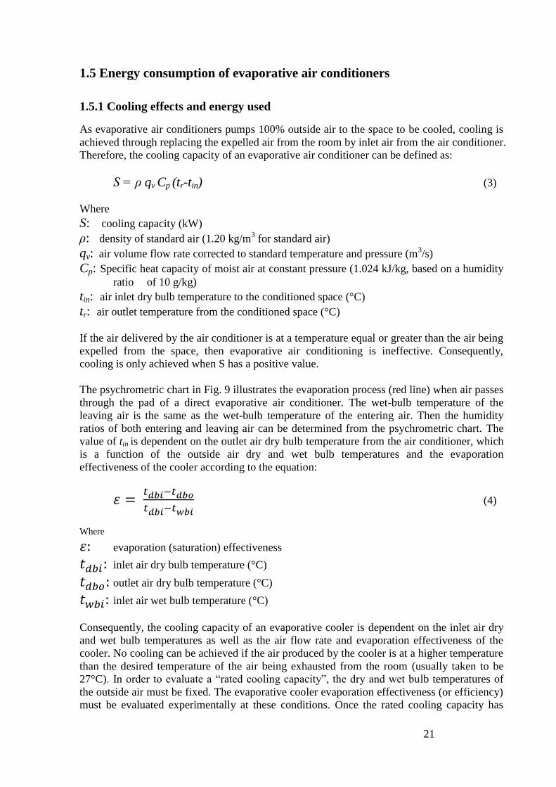
The psychrometric chart in Fig. 9 illustrates the evaporation process (red line) when air passes
through the pad of a direct evaporative air conditioner. The wet-bulb temperature of the
leaving air is the same as the wet-bulb temperature of the entering air. Then the humidity
ratios of both entering and leaving air can be determined from the psychrometric chart. The
value of tin is dependent on the outlet air dry bulb temperature from the air conditioner, which
is a function of the outside air dry and wet bulb temperatures and the evaporation
effectiveness of the cooler according to the equation:
(4)
Where
evaporation (saturation) effectiveness
inlet air dry bulb temperature (°C)
outlet air dry bulb temperature (°C)
inlet air wet bulb temperature (°C)
Consequently, the cooling capacity of an evaporative cooler is dependent on the inlet air dry
and wet bulb temperatures as well as the air flow rate and evaporation effectiveness of the
cooler. No cooling can be achieved if the air produced by the cooler is at a higher temperature
than the desired temperature of the air being exhausted from the room (usually taken to be
27°C). In order to evaluate a ―rated cooling capacity‖, the dry and wet bulb temperatures of
the outside air must be fixed. The evaporative cooler evaporation effectiveness (or efficiency)
must be evaluated experimentally at these conditions. Once the rated cooling capacity has
22
been established, a rated ―Energy Efficiency Ratio‖ can be determined as a measure of rating
the cooling effect being produced per unit electrical power being consumed.
(5)
Where
Energy Efficiency Ratio
cooling capacity (kW)
total input electrical Power (kW)
The total power consumption by the fan, pump and controller and the air flow rate under
conditions simulating the pressure losses in ducting along with all temperatures, must also be
measured at the same test under conditions simulating the rated outside dry and wet bulb
temperatures.
Figure 9: Psychrometrics of direct evaporative cooling.
1.5.2 Estimation of energy consumption in different parts of Australia
In an effort to provide indicative estimates of the energy required for evaporative air
conditioners, the energy consumption for cooling purposes has been calculated based on
typical yearly weather data for seven Australian cities (Adelaide, Brisbane, Canberra, Hobart,
Melbourne, Perth & Sydney) where cooling is necessary. The amount of energy consumption
for cooling purposes of the seven cities has been calculated based on the climatic data from
the Australian Climate Data Bank (ACDB). The results are presented in Tables 3 and 4. In
carrying out the calculation, it is assumed that the evaporation/saturation efficiency of the
cooling pad is 85%. The calculation is also based on a rule of thumb design guide used by
many suppliers which is that the evaporative air conditioner is assumed to be delivering the
equivalent volume of 30 air changes per hour. Two sizes of residential ducted units were
taken into consideration in the calculation:
Residential house with a conditioned area of 130m2 and a ceiling height of 2.4m. The
required air supply rate is 9360m3/h and the electricity consumption of the evaporative
cooler providing this air flow rate is estimated to be 810W.
Dry Bulb Temperature, °C
Hu
mid
ity ratio
, g m
oistu
re / kg
dry
air
Entering
air
Leaving
air

23
Residential house with a conditioned area of 200m2 and a ceiling height of 2.7m. The
required air supply rate is 16000m3/h and the electricity consumption of the evaporative
cooler is 1060W.
Table 3 shows that for all locations being considered except for Brisbane, there are only a few
hours in a typical year where a combination of high outside air temperature and high humidity
are encountered. This table demonstrates the suitability of direct evaporative air conditioners
to provide high cooling capacities and low temperature cooling in most Australian cities
except the tropical and semi tropical regions. Human thermal comfort can be normally
achieved when the temperature is below 27 °C and the moisture content is below 16 g/kg.
Therefore, the number of hours when the temperatures are above 27 °C and the moisture
content is above 16 g/kg for the different Australia locations have been specified in the table.
In order to have a better indication on the effectiveness of the evaporative cooler, the number
of hours that the dry bulb temperature of the air leaving the cooler that is above 25 °C are also
illustrated. The cooling capacity based on the air volume flow rate of 9,630 m3/hr and 16,000
m3/hr are calculated using Eqn. 3 for each hour of the day when cooling is deemed necessary
( when the outside dry bulb temperature is above 27 °C). The summation of the cooling
capacities will depict the total annual cooling capacity for each location. Dividing the total
annual cooling capacity by the number of hours when the outside dry bulb temperatures are
above 27 °C will result in the average cooling capacity.
Table 3: Estimates of cooling performance of Evaporative air conditioners for different unit sizes and
Australia locations.
Location
Duration
of
outside
dry bulb
temp
>27 °C
(hrs)
Duration
of cooler
moisture
content
>16 g/kg
(hrs)
Duration
of cooler
dry bulb
temp
>27 °C
(hrs)
Duration
of cooler
dry bulb
temp
>25 °C
(hrs)
Total annual
cooling capacity
(kWh)
Average
cooling
capacity
(kW)
9630
(m3/h)
16000
(m3/h)
9630
(m3/h)
16000
(m3/h)
Adelaide 845 38 4 18 20442.5 34944.5 24.2 41.4
Brisbane 572 325 0 39 7544.3 12896.3 13.2 22.5
Canberra 291 1 0 0 7845.3 13410.9 27.0 46.1
Hobart 36 0 0 0 867.6 1483.1 24.1 41.2
Melbourne 347 0 0 0 7401.8 12652.7 21.3 36.5
Perth 839 16 0 0 18261.8 31216.7 21.8 37.2
Sydney 276 100 0 0 4621.0 7452.1 16.7 28.6
The total annual electricity consumption to provide cooling during all hours when the outside
temperature is above 27°C has been calculated in Table 4 which demonstrates the low energy
consumption and cost associated with the use of these cooling systems. The table also
introduces a new parameter for evaluating the energy performance of evaporative air
conditioning systems, namely the Seasonal Energy Efficiency Ratio (SEER) which is the ratio
of annual cooling output of the air conditioner during the cooling season and the total annual
electrical energy usage to produce the cooling requirements. This ratio is a good measure of
the electrical energy effectiveness of cooling production under different climatic conditions. It
is a more comprehensive measure in comparison with the Energy Efficiency Ratio (EER)
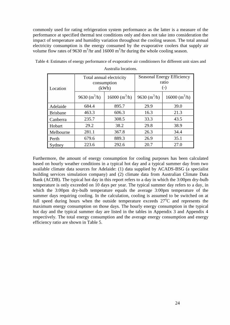
24
commonly used for rating refrigeration system performance as the latter is a measure of the
performance at specified thermal test conditions only and does not take into consideration the
impact of temperature and humidity variation throughout the cooling season. The total annual
electricity consumption is the energy consumed by the evaporative coolers that supply air
volume flow rates of 9630 m3/hr and 16000 m
3/hr during the whole cooling season.
Table 4: Estimates of energy performance of evaporative air conditioners for different unit sizes and
Australia locations.
Location
Total annual electricity
consumption
(kWh)
Seasonal Energy Efficiency
ratio
(-)
9630 (m3/h) 16000 (m
3/h) 9630 (m
3/h) 16000 (m
3/h)
Adelaide 684.4 895.7 29.9 39.0
Brisbane 463.3 606.3 16.3 21.3
Canberra 235.7 308.5 33.3 43.5
Hobart 29.2 38.2 29.8 38.9
Melbourne 281.1 367.8 26.3 34.4
Perth 679.6 889.3 26.9 35.1
Sydney 223.6 292.6 20.7 27.0
Furthermore, the amount of energy consumption for cooling purposes has been calculated
based on hourly weather conditions in a typical hot day and a typical summer day from two
available climate data sources for Adelaide: (1) data supplied by ACADS-BSG (a specialist
building services simulation company) and (2) climate data from Australian Climate Data
Bank (ACDB). The typical hot day in this report refers to a day in which the 3:00pm dry-bulb
temperature is only exceeded on 10 days per year. The typical summer day refers to a day, in
which the 3:00pm dry-bulb temperature equals the average 3:00pm temperature of the
summer days requiring cooling. In the calculation, cooling is assumed to be switched on at
full speed during hours when the outside temperature exceeds 27oC and represents the
maximum energy consumption on those days. The hourly energy consumption in the typical
hot day and the typical summer day are listed in the tables in Appendix 3 and Appendix 4
respectively. The total energy consumption and the average energy consumption and energy
efficiency ratio are shown in Table 5.

25
Table 5: Estimates of energy consumption of Evaporative air conditioners on typical days in Adelaide.
Conditions
Source
of
Climate
Data
Period requires
cooling
Total cooling
capacity for
various air flow
rates (kW)
Average
cooling
capacity for
various air flow
rates (kW)
Average EER
for various air
flow rates
Total electricity
consumed for
various air flow
rates (kWh)
9360
(m3/h)
16000
(m3/h)
9360
(m3/h)
16000
(m3/h)
9360
(m3/h)
16000
(m3/h)
9360
(m3/h)
16000
(m3/h)
Adelaide
typical hot
day
ACAD-
BSG 6:00am~12:00am 445.8 762.0 23.5 40.1 29.0 37.8 29.0 37.8
ACDB 11:00am~11:00pm 278.4 476.0 21.4 36.6 26.4 34.5 26.4 34.5
Adelaide
typical
summer
day
ACAD-
BSG 10:00am~7:00pm 221.5 378.6 22.1 37.9 27.3 35.7 27.3 35.7
ACDB 11:00am~8:00pm 250.7 428.5 25.1 42.8 30.9 40.4 30.9 40.4
1.6 Energy consumption of the components of evaporative air conditioners
The energy consuming components of an evaporative cooler are the fan motor, water pump
and controller (manual or remote). The breakdown of the power consumption of these
components for domestic applications under typical operation conditions are: fan motor
(230W to 2200W), water pump (30W to 136.8W) and controller (approximately 24W).
Details of the rated energy consumption for components of various brands and specifications
are found in Appendix 1.
26
2. Regulatory Approaches
2.1 Australian standards
AS/NZS 2913-2000: Evaporative Air-conditioning Equipment
In Australia, AS/NZS 2913-2000 is the only regulatory instrument available for testing
evaporative air conditioners. This Standard was prepared by Standards Australia Committee
ME-62, Ventilation and Air conditioning. It applies to evaporative air-conditioning devices
which cool air by the evaporation of water. It prescribes a basis for rating specified features of
evaporative air-conditioning equipment, and specifies the test procedures and equipment
applicable for rating an evaporative air conditioner. It also includes basic minimum
requirements for construction. The performance testing requirements are designed to evaluate:
Air flow
Evaporation efficiency
Sound power measurements
Electrical consumption
While the evaporation efficiency indicates how close the cooled air is to saturation point,
which is the maximum limit for direct evaporative air conditioners, it does not give a direct
indication of the cooling capacity or attempt to link it to the electricity consumption. Note that
the evaporation (saturation) efficiency is given as a percentage. It is also quoted as
evaporation effectiveness which is a fraction below 1. Typical evaporation efficiency values
are 70 - 85% (effectiveness 0.7- 0.85).
The Standard also includes information for evaluating a nominal rating for the evaluation of
the rated cooling performance for inlet dry and wet bulb temperatures of 38°C and 21°C
respectively and a room dry bulb temperature of 27.4°C.
The Standard contains a requirement that the electricity consumption of a particular unit
should be measured during the evaporation efficiency test. However, no energy rating is
available. The Standard also lacks requirements to evaluate the water consumption.
In addition, this Standard does not include requirements for evaluating the performance of
indirect or two stage evaporative air conditioners.
2.2 International regulations and standards
United States ANSI/ASHRAE Standard 133-2008: Method of Testing Direct Evaporative
Air Coolers
This Standard was prepared by the American Society for Heating, Refrigeration and Air
Conditioning Engineers (ASHRAE). It establishes a uniform test method for rating the
saturation effectiveness, airflow rate and total power of packaged and component direct
evaporative air coolers. Other parameters to be measured under equilibrium conditions are the
static pressure differential across the evaporative cooler, density of air and speed of rotation of
the fan. The Standard does require the measurement of flow rate of the supplied water and its
electrical conductivity as a measure of the water quality.

27
The Standard requires that the inlet plenum air dry-bulb temperature shall be 45oC maximum,
the wet-bulb temperature shall be 5oC minimum, and the difference between these two
temperatures shall be 11oC minimum during the testing period. It also requires that the
conductivity of the water supplied shall be between 350 and 3500 µS.
United States ANSI/ASHRAE Standard 143-2000: Method of Testing for Rating Indirect
Evaporative Coolers
This Standard was prepared by ASHRAE. It provides standard test methods and calculational
procedures for establishing the cooling capacities and power requirements for indirect
evaporative coolers. The indirect evaporative coolers can be either self-contained or
components of a packaged system. The parameters tested under steady-state conditions
include:
Air flow rates for primary and secondary airstreams
Dry-bulb and wet-bulb temperatures of both primary and secondary airstreams when
entering and leaving heat exchanger
Electrical consumption
However, the Standard does not include coolers using mechanical refrigeration or thermal
storage to cool the primary or secondary air streams. Also, it does not include coolers that dry
the primary or secondary airstreams. The Standard does not require the evaluation of water
consumption.
California Appliance Efficiency Regulations
The California Appliance Efficiency Regulations include a procedure for evaluating and
rating the energy performance of evaporative coolers. This is achieved by evaluating the
Evaporative Cooler Efficiency Ratio (ECER). ECER is evaluated by Eqn.6. The conditions
specified for the evaluation of ECER are intake dry and wet bulb temperatures of 32.8 and
20.6°C (91 and 69°F) respectively for testing the evaporation efficiency and assumed room
outlet air temperature of 26.7°C (80°F).
WQttttECER wbdbdbroom /)))(((.081 (6)
Where
roomt = room dry-bulb temperature, oC
dbt = outdoor dry-bulb temperature, oC
wbt = outdoor dry-bulb temperature, oC
= saturation effectiveness divided by 100
Q = air flow rate, cfm
W = total power, W
No water consumption requirements are included in the Regulations.
Iran Labelling Program
Iran is the only country that currently conducts a mandatory comparative labelling program
for energy consumption of evaporative air conditioners (see example of the label and rating,
Fig. 10 and Table 6). The label design is based on the European label concept but as a mirror
image with efficiency grades in numbers rather than letters (Persian script). It shows
efficiency grades from 1 (most efficient - the shortest bar, which appears in green on the
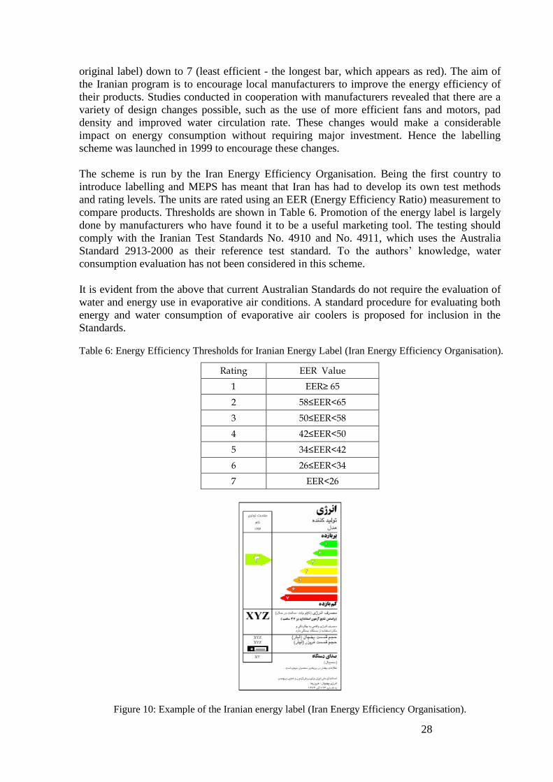
28
original label) down to 7 (least efficient - the longest bar, which appears as red). The aim of
the Iranian program is to encourage local manufacturers to improve the energy efficiency of
their products. Studies conducted in cooperation with manufacturers revealed that there are a
variety of design changes possible, such as the use of more efficient fans and motors, pad
density and improved water circulation rate. These changes would make a considerable
impact on energy consumption without requiring major investment. Hence the labelling
scheme was launched in 1999 to encourage these changes.
The scheme is run by the Iran Energy Efficiency Organisation. Being the first country to
introduce labelling and MEPS has meant that Iran has had to develop its own test methods
and rating levels. The units are rated using an EER (Energy Efficiency Ratio) measurement to
compare products. Thresholds are shown in Table 6. Promotion of the energy label is largely
done by manufacturers who have found it to be a useful marketing tool. The testing should
comply with the Iranian Test Standards No. 4910 and No. 4911, which uses the Australia
Standard 2913-2000 as their reference test standard. To the authors‘ knowledge, water
consumption evaluation has not been considered in this scheme.
It is evident from the above that current Australian Standards do not require the evaluation of
water and energy use in evaporative air conditions. A standard procedure for evaluating both
energy and water consumption of evaporative air coolers is proposed for inclusion in the
Standards.
Table 6: Energy Efficiency Thresholds for Iranian Energy Label (Iran Energy Efficiency Organisation).
Rating EER Value
1 EER≥ 65
2 58≤EER<65
3 50≤EER<58
4 42≤EER<50
5 34≤EER<42
6 26≤EER<34
7 EER<26
Figure 10: Example of the Iranian energy label (Iran Energy Efficiency Organisation).
29
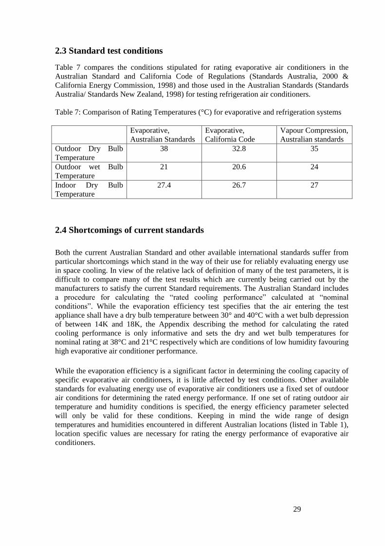
2.3 Standard test conditions
Table 7 compares the conditions stipulated for rating evaporative air conditioners in the
Australian Standard and California Code of Regulations (Standards Australia, 2000 &
California Energy Commission, 1998) and those used in the Australian Standards (Standards
Australia/ Standards New Zealand, 1998) for testing refrigeration air conditioners.
Table 7: Comparison of Rating Temperatures (°C) for evaporative and refrigeration systems
Evaporative,
Australian Standards
Evaporative,
California Code
Vapour Compression,
Australian standards
Outdoor Dry Bulb
Temperature
38 32.8 35
Outdoor wet Bulb
Temperature
21 20.6 24
Indoor Dry Bulb
Temperature
27.4 26.7 27
2.4 Shortcomings of current standards
Both the current Australian Standard and other available international standards suffer from
particular shortcomings which stand in the way of their use for reliably evaluating energy use
in space cooling. In view of the relative lack of definition of many of the test parameters, it is
difficult to compare many of the test results which are currently being carried out by the
manufacturers to satisfy the current Standard requirements. The Australian Standard includes
a procedure for calculating the ―rated cooling performance‖ calculated at ―nominal
conditions‖. While the evaporation efficiency test specifies that the air entering the test
appliance shall have a dry bulb temperature between 30° and 40°C with a wet bulb depression
of between 14K and 18K, the Appendix describing the method for calculating the rated
cooling performance is only informative and sets the dry and wet bulb temperatures for
nominal rating at 38°C and 21°C respectively which are conditions of low humidity favouring
high evaporative air conditioner performance.
While the evaporation efficiency is a significant factor in determining the cooling capacity of
specific evaporative air conditioners, it is little affected by test conditions. Other available
standards for evaluating energy use of evaporative air conditioners use a fixed set of outdoor
air conditions for determining the rated energy performance. If one set of rating outdoor air
temperature and humidity conditions is specified, the energy efficiency parameter selected
will only be valid for these conditions. Keeping in mind the wide range of design
temperatures and humidities encountered in different Australian locations (listed in Table 1),
location specific values are necessary for rating the energy performance of evaporative air
conditioners.

30
3. Testing/Rating Method
3.1 Review of available energy consumption testing procedure/methodology
Apart from the many references in the literature declaring the fact the energy consumption of
evaporative coolers being 20-50% of conventional vapour compression cooling systems, little
could be found in the international literature on methodologies proposed or being used for
rating evaporative air conditioners and comparing them with vapour compression systems.
Furthermore, no voluntary labelling programs covering evaporative air conditioners or
comparative or endorsement labels that include both evaporative and vapour compression air
conditioners could be found.
3.2 Development of a test methodology
It is proposed that both energy and water consumption testing be carried out using a single
test facility. A test rig presented in Fig. 11 is proposed to implement the testing for rating both
the energy and water consumption under controlled simulated outdoor temperature and
humidity conditions. The test requirements and conditions are to supplement current
Australian Standards AS/NZS 2913-2000 for measurement and will require additional
facilities for strict control to simulate the rating outdoor design conditions and input water
quality.
The test must comply with the following conditions:
Preset air temperature and humidity to simulate rating conditions with variation
allowed within specified tolerances
Input water quality to simulate mains water salinity level (measured by electrical
conductivity) within specified tolerances
Test measurements of new product to be carried out after a minimum number of hours
of operation, which would be a standardised time period
The following parameters need to be measured during the test after steady conditions have
been reached at each speed setting, for the purpose of evaluating both water and energy
performance:
Inlet and outlet dry and wet bulb temperatures
Air supply rates at different speed settings subject to a standardised pressure drop to
allow for the ducting system.
Electrical power consumption by the fan, water circulation pump and control/remote
systems
Pressure drop across the cooling system
Inlet water quality
Total water consumption
Total water dumped/bled off
Sound output level
The main significant output parameters of significance to energy/comfort considerations will
be evaluated at the rating conditions:
Evaporation effectiveness
Rated energy efficiency ratio; and
Cooling capacity
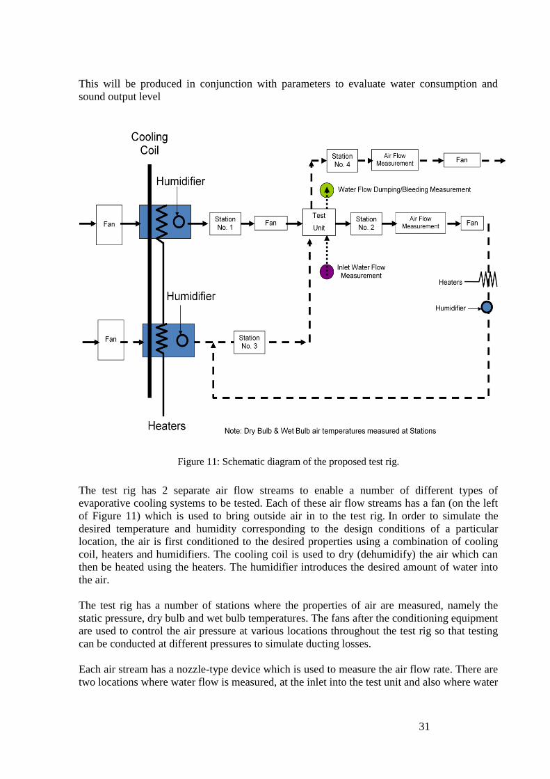
31
This will be produced in conjunction with parameters to evaluate water consumption and
sound output level
Figure 11: Schematic diagram of the proposed test rig.
The test rig has 2 separate air flow streams to enable a number of different types of
evaporative cooling systems to be tested. Each of these air flow streams has a fan (on the left
of Figure 11) which is used to bring outside air in to the test rig. In order to simulate the
desired temperature and humidity corresponding to the design conditions of a particular
location, the air is first conditioned to the desired properties using a combination of cooling
coil, heaters and humidifiers. The cooling coil is used to dry (dehumidify) the air which can
then be heated using the heaters. The humidifier introduces the desired amount of water into
the air.
The test rig has a number of stations where the properties of air are measured, namely the
static pressure, dry bulb and wet bulb temperatures. The fans after the conditioning equipment
are used to control the air pressure at various locations throughout the test rig so that testing
can be conducted at different pressures to simulate ducting losses.
Each air stream has a nozzle-type device which is used to measure the air flow rate. There are
two locations where water flow is measured, at the inlet into the test unit and also where water
32
dumping or bleeding occurs. The difference between the two is the water consumed in
cooling/humidifying the air.
In the test rig there is also another heater and humidifier (on the right of figure 11) which can
be used to simulate the heat load in a building. The heaters simulate heat and the humidifier
simulates moisture addition from perspiration and other sources.
3.3 Proposed test conditions
While the authors are unaware of the reasons behind the selection of the inlet air temperature
and humidity for evaporative air conditioner testing and rating, it is advisable that they should
be aligned with the values accepted by the wider air conditioning community which are those
used for rating other air conditioning systems in table 7 above. It is therefore proposed that the
outdoor dry and wet bulb temperatures used in the rating test procedure be modified to be
aligned with those used in vapour compression testing. From previous experience, it is
anticipated that the proposed changes will have little impact on the evaporation efficiency and
other output parameters of the tests which are almost independent of the test conditions within
the range under consideration. Furthermore, the parameter proposed below for rating the
seasonal energy consumption, while location sensitive will be little affected by the rating
conditions used in the test.
3.4 Proposed parameter for rating energy performance
Keeping in mind the performance sensitivity of evaporative air conditioners to the outdoor
temperature and humidity, a new parameter is proposed for providing the energy rating of
evaporative air conditioners. The proposed parameter is based on the annual performance of a
particular unit in a specific location. Using the test results (air supply rate, total electrical
power consumption and evaporation effectiveness) which are insensitive to temperature and
humidity variations, the hourly cooling capacity S for a specific unit can be evaluated in a
particular location for all hours of the year when cooling is required (temperature above 27oC)
as described in section 1.5 above. Typical year hourly weather data from the Australian
Climate Data Bank (ACDB) can be used for this purpose. The data will also enable an
estimation of the total electrical energy consumed during the hours of cooling. This enable the
evaluation of a new performance parameters which takes into consideration the overall annual
performance in a specific location, namely the Seasonal Energy Efficiency ratio, SEER,
where
(7)
33
3.5 Application of the proposed testing and rating procedures to new
technologies
Section 1 of this report has highlighted the emergence of new products which have been
developed to improve the comfort provisions of evaporative air conditioners throughout the
year by controlling the moisture content of the supplied air, namely indirect and two stage
evaporative air conditioners. The test procedure and methodology proposed in the report for
evaluating the energy and water use of evaporative air conditioners can be equally used for
the new products as well as the conventional systems. The test rig shown in Fig. 11 includes a
secondary air supply loop which is necessary for the indirect evaporative systems.
34
4. Performance Evaluation Information
4.1 Development of information for rating/labelling
Although evaporative air conditioners have been shown to generally consume less electrical
power compared with those based on refrigeration principles, their operation is only possible
in regions of low humidity where the air produced can be used to provide thermal comfort
cooling. In addition to their low energy consumption, other positive factors for their use are
the provision of 100% outside air and the high air velocities which decrease the perceived
operative temperature. On the other hand, the high humidity level associated with evaporative
air conditioners reduces the comfort perception.
Considering the Australian context, the climatic conditions in most Australian population
concentrations, except the tropical and semi tropical regions in Northern Australia, are
suitable for using evaporative cooling for most days in the year. Using typical performance
characteristics and typical year weather data for particular locations (specifically, the hourly
dry and wet bulb temperatures), the number of hours in the year when cooling is required, and
the number of hours when evaporative cooling is ineffective has been evaluated. This is a
significant piece of information which can be specified for particular evaporative coolers once
they have been tested as detailed in section 3 above. The information will assist the
consumers in determining their cooling system purchasing choice as well as governments
around Australia in making policy decisions on future energy and water requirements for air
conditioning.
4.2 Proposed information for rating/labelling
Both consumers and regulators require specific information to describe the performance of
evaporative air conditioners. Standardised information is necessary so that consumers can
compare between different products in order to make the purchasing decision. The
information outlets may comprise the following:
1. Manufacturers‘/suppliers‘ product information available on their websites, product
information booklets and publicity material
2. Government or independent publications and websites such as the energy rating
website www.energyrating.gov.au and the WELS water rating website
3. Rating labels affixed on the products (mandatory or voluntary)
The previous sections of this report have shown that once a specific evaporative air
conditioner has been subjected to a standard test (as described in section 3), a number of key
parameters can be evaluated to describe its performance at a particular location. As the rated
evaporation effectiveness and power consumption are almost independent of the climatic
condition for a particular air delivery rate, these will enable the evaluation of the following
parameters for a particular system:
1. Its cooling capabilities and potential provision of thermal comfort through the following
parameters:
Cooling capacity at the location design conditions
Number of hours per year when the system is unable to provide thermal comfort or as
a percentage of hours when cooling is required. The provision of thermal comfort is
deemed achievable at a particular hour if the outlet temperature of the evaporative air
conditioner does not exceed 25°C.
35
2. Its daily and annual energy consumption and cost through:
Average daily electrical energy use for cooling at the design conditions of the specific
location
Annual energy consumption and cost of cooling at the specific location
Energy use per kW of cooling
3. Its maximum power demand and contribution to the grid peak demand
4. Its greenhouse gas emission per kW of cooling and total annual greenhouse gas emission
This information along with similar parameters for water consumption will provide useful
data to consumers at the purchase stage. It is also significant for industry in aiding
competition and product development data. Government agencies will use the data in policy
formulation and planning.
4.3 A parameter for rating the energy performance of evaporative air
conditioners
In addition to the parameters proposed above for informing the stakeholders on the energy
and water consumptions of evaporative air conditioners, a single rating tool is necessary for
rating the energy consumption of different evaporative conditioners. The rating parameter will
enable direct comparison of different models. In order to enable the making of informed
purchasing decisions, the parameter should enable direct comparison with the performance of
vapour compression air conditioners.
The seasonal Energy efficiency Ratio (SEER) as described in section 3.4 above is proposed.
This SEER value is location specific. However, it is comparable with the EER values quoted
for other cooling systems as the latter gives an indication of the cooling effect produced per
unit electrical energy consumption at the standard test conditions. It is worth mentioning in
this context that SEER values can be evaluated for other types of air conditioners and is in
deed used in some countries as a means of providing good estimates of annual energy
consumption. However, this would require performance evaluation at a number of test
conditions rather than a single rating condition in current use.
The current energy star rating methodology of air conditioners is directly based on the rated
EER value. As shown in Table 8, cooling star rating is 1 for an EER value of 2.75. The rating
increases by one star for each 0.5 increase in the EER. As the proposed test conditions for
evaporative air conditioners is the same as the current test conditions for refrigeration air
conditioners, the measured EER values of specific refrigeration and evaporative air
conditioners can be used for a quick comparison between 2 specific appliances being
considered for a particular application.
It is proposed that SEER be converted to equivalent rating of evaporative air conditioners
using the equations developed for rating other air conditioners. This will serve as a means of
indirectly comparing the energy performance of evaporative coolers with other systems. It
will also reflect the suitability of evaporative air conditioning for use in particular locations. It
must be stressed here that the proposed methodology will be entirely separate from the star
rating system in use for refrigeration systems. The proposed rating methodology will produce
star ratings of above 10 for evaporative air conditioners. However, the two methods give
direct comparisons of the effectiveness of using electrical energy to generate a unit of cooling.
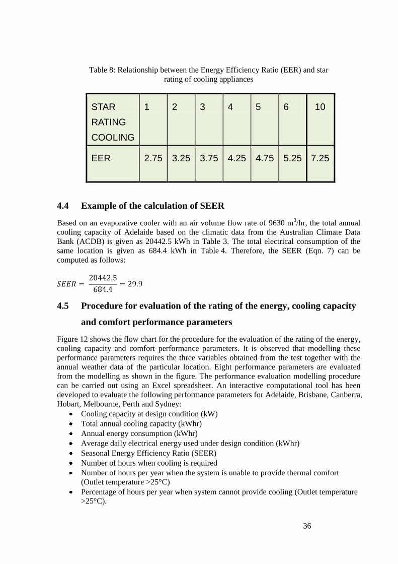
36
Table 8: Relationship between the Energy Efficiency Ratio (EER) and star
rating of cooling appliances
STAR
RATING
COOLING
1 2 3 4 5 6 10
EER
2.75 3.25 3.75 4.25 4.75 5.25 7.25
4.4 Example of the calculation of SEER
Based on an evaporative cooler with an air volume flow rate of 9630 m3/hr, the total annual
cooling capacity of Adelaide based on the climatic data from the Australian Climate Data
Bank (ACDB) is given as 20442.5 kWh in Table 3. The total electrical consumption of the
same location is given as 684.4 kWh in Table 4. Therefore, the SEER (Eqn. 7) can be
computed as follows:
4.5 Procedure for evaluation of the rating of the energy, cooling capacity
and comfort performance parameters
Figure 12 shows the flow chart for the procedure for the evaluation of the rating of the energy,
cooling capacity and comfort performance parameters. It is observed that modelling these
performance parameters requires the three variables obtained from the test together with the
annual weather data of the particular location. Eight performance parameters are evaluated
from the modelling as shown in the figure. The performance evaluation modelling procedure
can be carried out using an Excel spreadsheet. An interactive computational tool has been
developed to evaluate the following performance parameters for Adelaide, Brisbane, Canberra,
Hobart, Melbourne, Perth and Sydney:
Cooling capacity at design condition (kW)
Total annual cooling capacity (kWhr)
Annual energy consumption (kWhr)
Average daily electrical energy used under design condition (kWhr)
Seasonal Energy Efficiency Ratio (SEER)
Number of hours when cooling is required
Number of hours per year when the system is unable to provide thermal comfort
(Outlet temperature >25°C) Percentage of hours when cooling is required but t
Percentage of hours per year when system cannot provide cooling (Outlet temperature
>25°C).
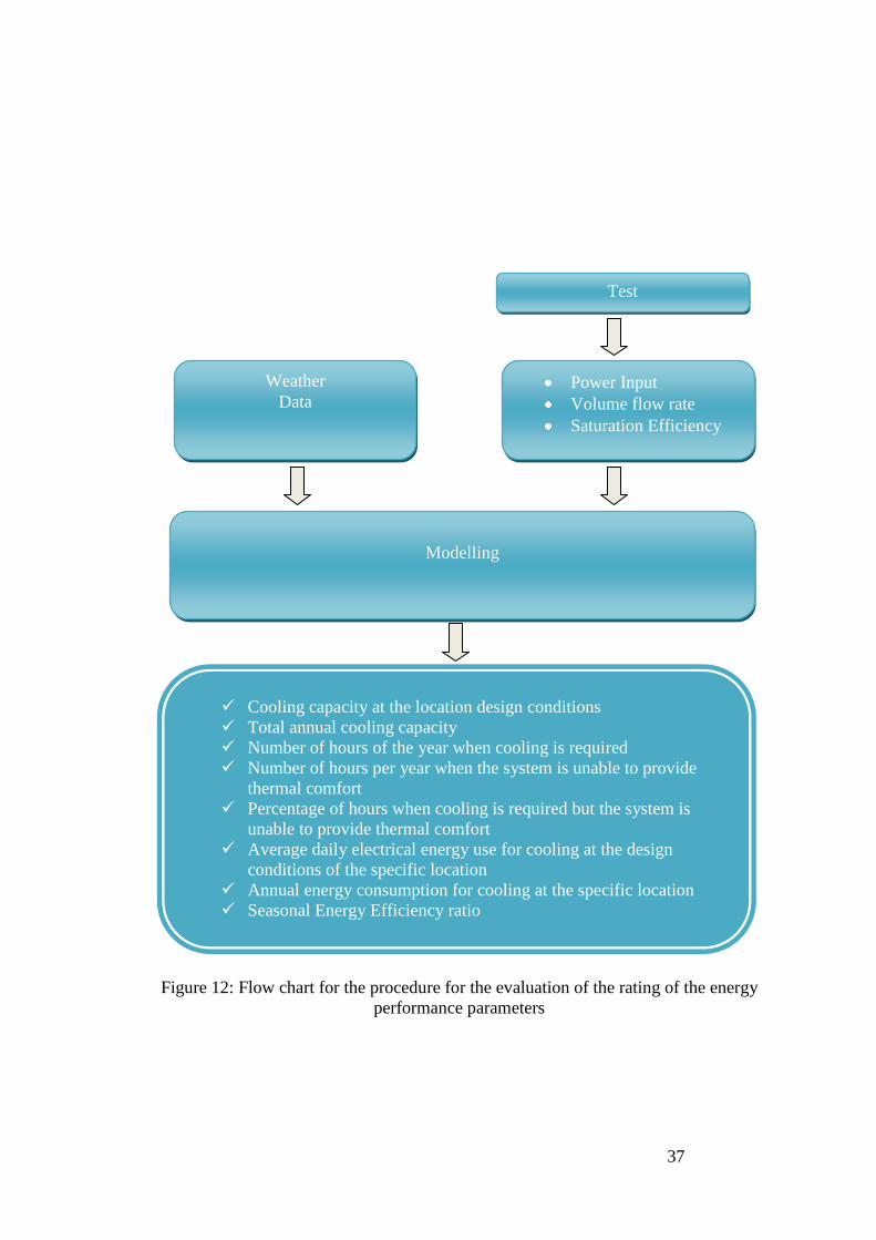
37
Figure 12: Flow chart for the procedure for the evaluation of the rating of the energy
performance parameters
Test
Test
Power Input
Volume flow rate
Saturation Efficiency
Cooling capacity at the location design conditions
Total annual cooling capacity
Number of hours of the year when cooling is required
Number of hours per year when the system is unable to provide
thermal comfort
Percentage of hours when cooling is required but the system is
unable to provide thermal comfort
Average daily electrical energy use for cooling at the design
conditions of the specific location
Annual energy consumption for cooling at the specific location
Seasonal Energy Efficiency ratio
Seasonal Energy Efficiency Ratio
Modelling
Weather
Data
38
5. Conclusions and recommendations The report has highlighted the current status, recent developments, challenges and features of
evaporative air conditions which are locally produced products. In order to fill the
information gap on their energy (and water) requirements, a standard test procedure is
proposed to enable the characterisation of different units. A number of parameters have been
proposed to enable assessment of their suitability and energy consumption in different
Australian locations. The Seasonal Energy Efficiency ratio is proposed as a single parameter
for defining the energy consumption of evaporative air conditioners and enabling comparison
with refrigeration cooling units. An interactive computational tool has been developed for
evaluating these performance parameters.
In order to implement the proposed testing/rating regime, the following steps are proposed:
1. Early consultation with manufacturers, suppliers, governments and users groups will
be an important step in progressing a labelling/rating system for energy and water use in
evaporative air conditioners. The consultative process need to consider the following issues:
Suitability of the proposed standard test methodology
Defining specific test conditions (dry and wet bulb temperatures, indoor
temperature, pad conditions, water conditions and static pressure drop)
Range of sizes of units to be subjected to testing/rating
Testing at different speed settings
Incorporation of thermostat setting in cooling calculations
The need to use the same test facility and procedures for testing/rating indirect
and two stage systems
Suitability and appropriateness of the proposed parameters for providing
rating/labelling information
Choice of Australian locations for evaluating the proposed rating/labelling
parameters
Suitability and appropriateness of the proposed location specific Seasonal Energy
Efficiency Ratio as the key energy rating parameter
Suitability and effectiveness of using the star rating relationship currently used for
refrigeration cooling system as a means for providing the equivalent star rating of
evaporative air conditioner
2. Once a consensus is reached on fixing the items listed above, a more detailed study to
develop a standard testing procedure, required testing facilities and methodology for
independent testing, rating/labelling of both water and energy use in evaporative air
conditioners is recommended as the next step for progressing the rating of these systems. This
should also incorporate modifications to the current testing standard in AS/NZS 2913-2000
Evaporative air conditioning equipment.
39
References AIRAH technical handbook (2007), The Australian Institute of Refrigeration, Air Conditioning
and Heating, Inc.
ANSI/ASHRAE Standard 143-2000 (2000), Method of Test for Rating Indirect Evaporative Coolers, American Society of Heating, Refrigerating and Air-Conditioning Engineers, Inc.,
Atlanta.
ANSI/ASHRAE Standard 133-2008 (2008), Method of Testing Direct Evaporative Coolers, American Society of Heating, Refrigerating and Air-Conditioning Engineers, Inc., Atlanta.
ASHRAE Handbook (2007), HVAC Applications, American Society of Heating, Refrigerating
and Air-Conditioning Engineers, Inc., Atlanta.
ASHRAE Handbook (2004), HVAC Systems and Equipment, American Society of Heating,
Refrigerating and Air-Conditioning Engineers, Inc., Atlanta.
Australian Bureau of Statistics (1988), National Energy Survey: Weekly Reticulated Energy and Appliance Usage Patterns by Season Households, Australia 1985-86. (cat no. 8218.0).
Australian Bureau of Statistics (2007), Environmental Issues: People’s Views and Practices (cat no. 4602.0). Available on:
http://www.abs.gov.au/AUSSTATS/[email protected]/DetailsPage/4602.0Mar%202007?OpenDocument.
Australian Bureau of Statistics (2008), Environmental Issues: Energy Use and Conservation (cat no. 4602.0.55.001). Available on:
http://www.abs.gov.au/AUSSTATS/[email protected]/DetailsPage/4602.0.55.001Mar%202008?OpenD
ocument.
American Society of Heating, Refrigerating and Air Conditioning engineers, 2001,
‗Method of Testing Direct Evaporative Air Coolers ANSI/ASHRAE Standard 133-2001’
American Society of Heating, Refrigerating and Air Conditioning engineers, 2000,
‗Method of Test for Rating Indirect Evaporative Air Coolers ANSI/ASHRAE Standard 143-
2000’
Bom, G.J. (1999), Evaporative air-conditioning, World Bank Publications.
California Energy Commission, 1998, ‗Appliance energy Regulations, California Code of
Regulations’, Title 20, CEC-400-2006-002.
California Energy Commission (2006), California Appliance Efficiency Regulations, CEC-400-
2006-002-REV2.
Energy Efficiency Strategies, 2006, ‗Status of Air Conditioners in Australia –Updated with
2005 data‘ report prepared for the National Appliance and Equipment Energy Efficiency
Committee.

40
Energy Efficient Strategies (2008), Regulatory Impact Statement for Revision to the Energy Labelling Algorithms and Revised MEPs levels and Other Requirements for Air Conditioners. Available on: http://www.energyrating.gov.au/library/details200809-ris-ac.html.
Energyconsult PTY Ltd, 2002 ‘Voluntary Energy Labelling Possibilities for Evaporative and
Refrigerative Air Conditioners’ Report no:2002/05, Final Report prepared for the Australian
Greenhouse Office
Heidarinejad, G., Bozorgmehr, M., Delfani, S. & Esmaeelian, J. (2009), Experimental Investigation of Two-stage Indirect/direct Evaporative Cooling System in Various Climatic Conditions, Building and Environment, doi:10.1016/j.buildenv.2009.02.017.
Iran Energy Efficiency Organisation, www.iraneeo.com.
Pescod, D., (1968), Unit Air Cooler using Plastic Heat Exchanger with Evaporatively Cooled Pads. Australian Refrigeration Air Conditioning and Heating, 22, 9, 22.
Pescod, D., (1979), A Heat Exchanger for Energy Savings in Air Conditioning Plant. ASHRAE,
Trans. 85, 2, 238.
Saman, W.Y., (1993), Developments in Evaporative and Desiccant Cooling Systems and their Potential Application in Australia. Proc. Australasian Heat and Mass Transfer Conference,
Brisbane.
Saman, W.Y, (1994), Energy Conscious Ventilation with Indirect Heating and Cooling for Better Air Quality. Proc Indoor Health and Comfort Seminar, The Australian Institute of
Refrigeration, Air Conditioning and Heating.
Saman, W. and Mudge, L. 2002, ‗Development, Implementation and Promotion of a
Scoresheet for Household Greenhouse Gas Reduction in South Australia, Final Report
submitted to the Australian Greenhouse Office, Sustainable Energy Centre, University of
South Australia.
Saman, W.Y, Bruno, F. (2008), Developing a Methodology for Rating Evaporative Air
Conditioners. Report Submitted to the Australian Evaporative Air conditioner Manufacturers
and to Australian State and Commonwealth Governments, March, 2008.
Saman, W.Y., and Kilsby, R., (1999), Energy Efficient Heating, Dehumidification and Cooling System. Proc OzTech99, Taiwan.
Saman, W.Y., Percy, A., Sardelis, P., and McNab J., (1995), A Comparison between a Conventional Heat Pump System and One Incorporating Heat Recovery/Evaporative Cooling. Proc International Symposium on Energy, Environment and Economics, University of
Melbourne.
Standards Australia (2000), Evaporative Air conditioning Equipment AS 2913-2000. Standards Australia/ Standards New Zealand, (1998), Performance of Electrical Appliances- Airconditioners and Heat Pumps, Part 1.1: Non-Ducted Airconditioners and Heat Pumps-Testing and Rating for Performance, AS/NZS 3823.1.1:1998’.

41
Wang, S.K., Lavan, Z., Kreith, F., & Norton, P. (2000), Air Conditioning and Refrigeration Engineering, CRC Press.
www.energyrating.gov.au
http://www.wapa.gov/es/pubs/esb/2005/june/jun057.htm
http://www.coolerado.com/news/articles/
http://www.climatewizard.com.au/pdf/Climate%20Wizard%20brochure%200909.pdf
http://www.climatewizard.com.au/
http://www.homeheat.com.au/pdf/fact.pdf
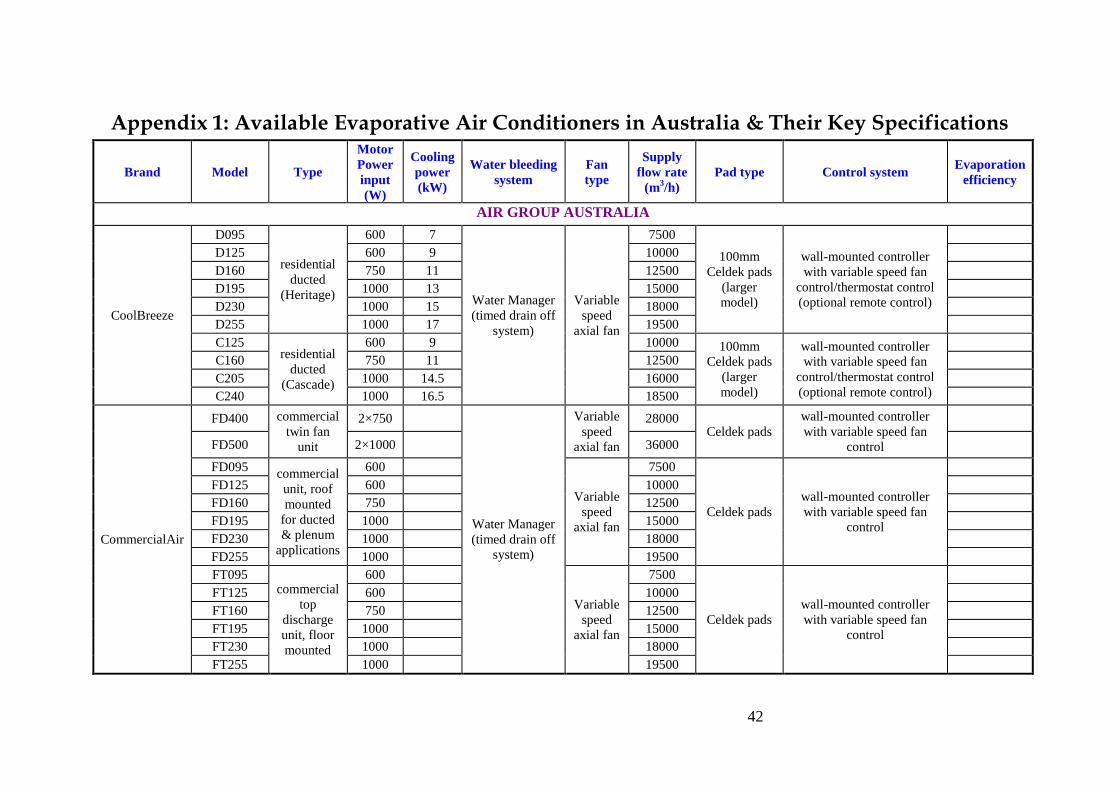
42
Appendix 1: Available Evaporative Air Conditioners in Australia & Their Key Specifications
Brand Model Type
Motor
Power
input
(W)
Cooling
power
(kW)
Water bleeding
system
Fan
type
Supply
flow rate
(m3/h)
Pad type Control system Evaporation
efficiency
AIR GROUP AUSTRALIA
CoolBreeze
D095
residential
ducted
(Heritage)
600 7
Water Manager
(timed drain off
system)
Variable
speed
axial fan
7500
100mm
Celdek pads
(larger
model)
wall-mounted controller
with variable speed fan
control/thermostat control
(optional remote control)
D125 600 9 10000
D160 750 11 12500
D195 1000 13 15000
D230 1000 15 18000
D255 1000 17 19500
C125 residential
ducted
(Cascade)
600 9 10000 100mm
Celdek pads
(larger
model)
wall-mounted controller
with variable speed fan
control/thermostat control
(optional remote control)
C160 750 11 12500
C205 1000 14.5 16000
C240 1000 16.5 18500
CommercialAir
FD400 commercial
twin fan
unit
2×750
Water Manager
(timed drain off
system)
Variable
speed
axial fan
28000 Celdek pads
wall-mounted controller
with variable speed fan
control
FD500 2×1000 36000
FD095 commercial
unit, roof
mounted
for ducted
& plenum
applications
600
Variable
speed
axial fan
7500
Celdek pads
wall-mounted controller
with variable speed fan
control
FD125 600 10000
FD160 750 12500
FD195 1000 15000
FD230 1000 18000
FD255 1000 19500
FT095 commercial
top
discharge
unit, floor
mounted
600
Variable
speed
axial fan
7500
Celdek pads
wall-mounted controller
with variable speed fan
control
FT125 600 10000
FT160 750 12500
FT195 1000 15000
FT230 1000 18000
FT255 1000 19500
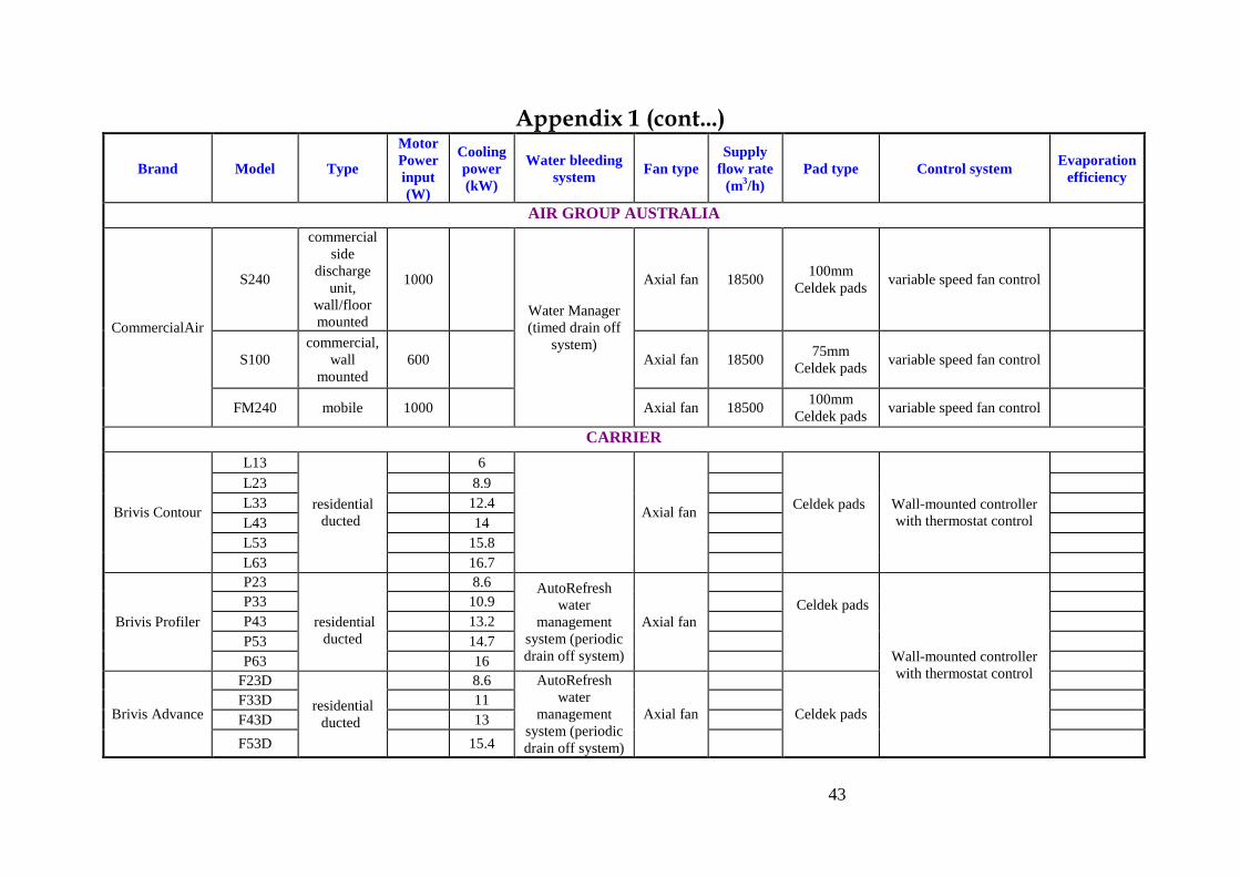
43
Appendix 1 (cont...)
Brand Model Type
Motor
Power
input
(W)
Cooling
power
(kW)
Water bleeding
system Fan type
Supply
flow rate
(m3/h)
Pad type Control system Evaporation
efficiency
AIR GROUP AUSTRALIA
CommercialAir
S240
commercial
side
discharge
unit,
wall/floor
mounted
1000
Water Manager
(timed drain off
system)
Axial fan 18500 100mm
Celdek pads variable speed fan control
S100
commercial,
wall
mounted
600 Axial fan 18500 75mm
Celdek pads variable speed fan control
FM240 mobile 1000 Axial fan 18500 100mm
Celdek pads variable speed fan control
CARRIER
Brivis Contour
L13
residential
ducted
6
Axial fan
Celdek pads
Wall-mounted controller
with thermostat control
L23 8.9
L33 12.4
L43 14
L53 15.8
L63 16.7
Brivis Profiler
P23
residential
ducted
8.6 AutoRefresh
water
management
system (periodic
drain off system)
Axial fan
Celdek pads
Wall-mounted controller
with thermostat control
P33 10.9
P43 13.2
P53 14.7
P63 16
Brivis Advance
F23D
residential
ducted
8.6 AutoRefresh
water
management
system (periodic
drain off system)
Axial fan
Celdek pads
F33D 11
F43D 13
F53D 15.4
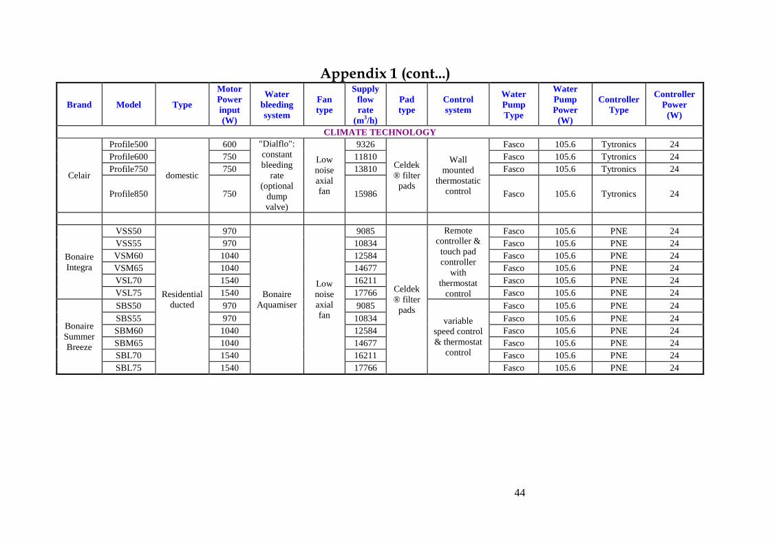
44
Appendix 1 (cont...)
Brand Model Type
Motor
Power
input
(W)
Water
bleeding
system
Fan
type
Supply
flow
rate
(m3/h)
Pad
type
Control
system
Water
Pump
Type
Water
Pump
Power
(W)
Controller
Type
Controller
Power
(W)
CLIMATE TECHNOLOGY
Celair
Profile500
domestic
600 "Dialflo":
constant
bleeding
rate
(optional
dump
valve)
Low
noise
axial
fan
9326
Celdek
® filter
pads
Wall
mounted
thermostatic
control
Fasco 105.6 Tytronics 24
Profile600 750 11810 Fasco 105.6 Tytronics 24
Profile750 750 13810 Fasco 105.6 Tytronics 24
Profile850 750 15986 Fasco 105.6 Tytronics 24
Bonaire
Integra
VSS50
Residential
ducted
970
Bonaire
Aquamiser
Low
noise
axial
fan
9085
Celdek
® filter
pads
Remote
controller &
touch pad
controller
with
thermostat
control
Fasco 105.6 PNE 24
VSS55 970 10834 Fasco 105.6 PNE 24
VSM60 1040 12584 Fasco 105.6 PNE 24
VSM65 1040 14677 Fasco 105.6 PNE 24
VSL70 1540 16211 Fasco 105.6 PNE 24
VSL75 1540 17766 Fasco 105.6 PNE 24
Bonaire
Summer
Breeze
SBS50 970 9085
variable
speed control
& thermostat
control
Fasco 105.6 PNE 24
SBS55 970 10834 Fasco 105.6 PNE 24
SBM60 1040 12584 Fasco 105.6 PNE 24
SBM65 1040 14677 Fasco 105.6 PNE 24
SBL70 1540 16211 Fasco 105.6 PNE 24
SBL75 1540 17766 Fasco 105.6 PNE 24
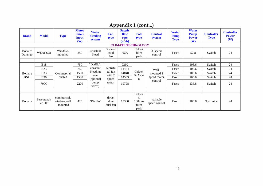
45
Appendix 1 (cont...)
Brand Model Type
Motor
Power
input
(W)
Water
bleeding
system
Fan
type
Supply
flow
rate
(m3/h)
Pad
type
Control
system
Water
Pump
Type
Water
Pump
Power
(W)
Controller
Type
Controller
Power
(W)
CLIMATE TECHNOLOGY
Bonaire
Durango WEAC628
Window-
mounted 250
Constant
bleed
3 speed
axial
fan
4500
Celdek
filter
pads
3 speed
control Fasco 52.8 Switch 24
Bonaire
B&C
B18
Commercial
ducted
750 "Dialflo":
constant
bleeding
rate
(optional
dump
valve)
centrifu
gal fan
with 2
speed
motor
9360
Celdek
®/Aspe
n
Wall-
mounted 2
speed motor
control
Fasco 105.6 Switch 24
B23 750 11484 Fasco 105.6 Switch 24
B33 1500 14040 Fasco 105.6 Switch 24
B36 1500 14583 Fasco 105.6 Switch 24
700C 2200 19798 Fasco 136.8 Switch 24
Bonaire Seasonmak
er DF
commercial,
window,wall
-mounted
425 "Dialflo"
direct
dive
dual fan
13300
Celdek
®
100mm
filter
pads
variable
speed control Fasco 105.6 Tytronics 24
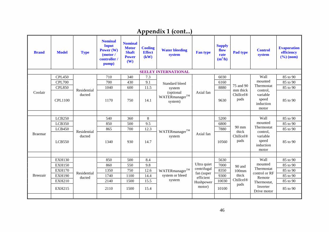
46
Appendix 1 (cont...)
Brand Model Type
Nominal
Input
Power (W)
(motor /
controller /
pump)
Nominal
Motor
Shaft
Power
(W)
Cooling
Effect
(kW)
Water bleeding
system Fan type
Supply
flow
rate
(m3/h)
Pad type Control
system
Evaporation
efficiency
(%) (nom)
SEELEY INTERNATIONAL
Coolair
CPL450
Residential
ducted
710 340 7.3
Standard bleed
system
(optional
WATERmanagerTM
system)
Axial fan
6030
75 and 90
mm thick
Chillcel®
pads
Wall
mounted
Thermostat
control,
variable
speed
induction
motor
85 to 90
CPL700 700 430 9.1 6160 85 to 90
CPL850 1040 600 11.5 8880 85 to 90
CPL1100 1170 750 14.1 9630 85 to 90
Braemar
LCB250
Residential
ducted
540 360 8
WATERmanagerTM
system Axial fan
5200
90 mm
thick
Chillcel®
pads
Wall
mounted
Thermostat
control,
variable
speed
induction
motor
85 to 90
LCB350 850 500 9.5 6800 85 to 90
LCB450 865 700 12.3 7880 85 to 90
LCB550 1340 930 14.7 10560 85 to 90
Breezair
EXH130
Residential
ducted
850 500 8.4
WATERmanagerTM
system or bleed
system
Ultra quiet
centrifugal
fan (super
efficient
Hushpower
motor)
5630
90 and
100mm
thick
Chillcel®
pads
Wall
mounted
Thermostat
control or RF
Remote
Thermostat,
Inverter
Drive motor
85 to 90
EXH150 860 550 9.8 7000 85 to 90
EXH170 1350 750 12.6 8350 85 to 90
EXH190 1740 1100 14.4 9300 85 to 90
EXH210 2140 1500 15.5 10030 85 to 90
EXH215 2110 1500 15.4 10100 85 to 90
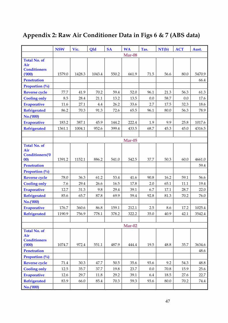
47
Appendix 2: Raw Air Conditioner Data in Figs 6 & 7 (ABS data)
NSW Vic. Qld SA WA Tas. NT(b) ACT Aust.
Mar-08 Total No. of Air Conditioners ('000) 1579.0 1428.3 1043.4 550.2 661.9 71.5 56.6 80.0 5470.9
Penetration 66.4
Proportion (%)
Reverse cycle 77.7 41.9 70.2 59.4 52.0 96.1 21.3 56.3 61.3
Cooling only 8.5 28.4 21.1 13.2 13.5 0.0 58.7 0.0 17.6
Evaporative 11.6 27.1 4.4 26.2 33.6 2.7 17.5 32.3 18.6
Refrigerated 86.2 70.3 91.3 72.6 65.5 96.1 80.0 56.3 78.9
No.('000)
Evaporative 183.2 387.1 45.9 144.2 222.4 1.9 9.9 25.8 1017.6
Refrigerated 1361.1 1004.1 952.6 399.4 433.5 68.7 45.3 45.0 4316.5
Mar-05 Total No. of Air Conditioners('000) 1391.2 1152.1 886.2 541.0 542.5 37.7 50.3 60.0 4661.0
Penetration 59.4
Proportion (%)
Reverse cycle 78.0 36.3 61.2 53.4 41.6 90.8 16.2 59.1 56.6
Cooling only 7.6 29.4 26.6 16.5 17.8 2.0 65.1 11.1 19.4
Evaporative 12.7 31.3 9.8 29.4 39.1 6.7 17.1 28.7 22.0
Refrigerated 85.6 65.7 87.8 69.9 59.4 92.8 81.3 70.2 76.0
No.('000)
Evaporative 176.7 360.6 86.8 159.1 212.1 2.5 8.6 17.2 1025.4
Refrigerated 1190.9 756.9 778.1 378.2 322.2 35.0 40.9 42.1 3542.4
Mar-02 Total No. of Air Conditioners ('000) 1074.7 972.4 551.1 487.9 444.4 19.5 48.8 35.7 3634.6
Penetration 48.6
Proportion (%)
Reverse cycle 71.4 30.3 47.7 50.5 35.6 93.6 9.2 54.3 48.8
Cooling only 12.5 35.7 37.7 19.8 23.7 0.0 70.8 15.9 25.6
Evaporative 12.6 29.7 11.8 29.2 39.1 6.4 18.5 27.6 22.7
Refrigerated 83.9 66.0 85.4 70.3 59.3 93.6 80.0 70.2 74.4
No.('000)
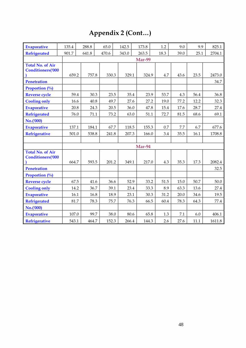
48
Appendix 2 (Cont…)
Evaporative 135.4 288.8 65.0 142.5 173.8 1.2 9.0 9.9 825.1
Refrigerated 901.7 641.8 470.6 343.0 263.5 18.3 39.0 25.1 2704.1
Mar-99 Total No. of Air Conditioners('000) 659.2 757.8 330.3 329.1 324.9 4.7 43.6 23.5 2473.0
Penetration 34.7
Proportion (%)
Reverse cycle 59.4 30.3 23.5 35.4 23.9 53.7 4.3 56.4 36.8
Cooling only 16.6 40.8 49.7 27.6 27.2 19.0 77.2 12.2 32.3
Evaporative 20.8 24.3 20.5 36.0 47.8 15.4 17.6 28.7 27.4
Refrigerated 76.0 71.1 73.2 63.0 51.1 72.7 81.5 68.6 69.1
No.('000)
Evaporative 137.1 184.1 67.7 118.5 155.3 0.7 7.7 6.7 677.6
Refrigerative 501.0 538.8 241.8 207.3 166.0 3.4 35.5 16.1 1708.8
Mar-94 Total No. of Air Conditioners('000) 664.7 593.5 201.2 349.1 217.0 4.3 35.3 17.3 2082.4
Penetration 32.5
Proportion (%)
Reverse cycle 67.5 41.6 36.6 52.9 33.2 51.5 15.0 50.7 50.0
Cooling only 14.2 36.7 39.1 23.4 33.3 8.9 63.3 13.6 27.4
Evaporative 16.1 16.8 18.9 23.1 30.3 31.2 20.0 34.6 19.5
Refrigerated 81.7 78.3 75.7 76.3 66.5 60.4 78.3 64.3 77.4
No.('000)
Evaporative 107.0 99.7 38.0 80.6 65.8 1.3 7.1 6.0 406.1
Refrigerative 543.1 464.7 152.3 266.4 144.3 2.6 27.6 11.1 1611.8
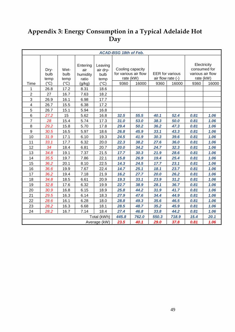
49
Appendix 3: Energy Consumption in a Typical Adelaide Hot Day
ACAD-BSG 18th of Feb.
Time
Dry-bulb temp (°C)
Wet-bulb temp (°C)
Entering air
humidity ratio
(g/kg)
Leaving air dry-
bulb temp (°C)
Cooling capacity for various air flow
rate (kW) EER for various air flow rate (-)
Electricity consumed for
various air flow rate (kW)
9360 16000 9360 16000 9360 16000
1 26.8 17.2 8.31 18.6
2 27 16.7 7.63 18.2
3 26.9 16.1 6.98 17.7
4 26.7 15.5 6.38 17.2
5 26.7 15.1 5.94 16.8
6 27.2 15 5.62 16.8 32.5 55.5 40.1 52.4 0.81 1.06
7 28 15.4 5.74 17.3 31.0 53.0 38.3 50.0 0.81 1.06
8 29.2 15.8 5.70 17.8 29.4 50.2 36.2 47.3 0.81 1.06
9 30.5 16.5 5.97 18.6 26.8 45.9 33.1 43.3 0.81 1.06
10 31.9 17.1 6.10 19.3 24.5 41.9 30.3 39.6 0.81 1.06
11 33.1 17.7 6.32 20.0 22.3 38.2 27.6 36.0 0.81 1.06
12 34 18.4 6.81 20.7 20.0 34.2 24.7 32.3 0.81 1.06
13 34.8 19.1 7.37 21.5 17.7 30.3 21.9 28.6 0.81 1.06
14 35.5 19.7 7.86 22.1 15.8 26.9 19.4 25.4 0.81 1.06
15 36.2 20.1 8.10 22.5 14.3 24.5 17.7 23.1 0.81 1.06
16 36.6 19.9 7.67 22.4 14.7 25.1 18.1 23.7 0.81 1.06
17 36.2 19.4 7.18 21.9 16.2 27.7 20.0 26.2 0.81 1.06
18 34.8 18.5 6.61 20.9 19.3 33.1 23.9 31.2 0.81 1.06
19 32.8 17.6 6.32 19.9 22.7 38.9 28.1 36.7 0.81 1.06
20 30.9 16.8 6.15 18.9 25.8 44.2 31.9 41.7 0.81 1.06
21 29.5 16.3 6.14 18.3 27.9 47.6 34.4 44.9 0.81 1.06
22 28.6 16.1 6.28 18.0 28.8 49.3 35.6 46.5 0.81 1.06
23 28.2 16.3 6.68 18.1 28.5 48.7 35.2 45.9 0.81 1.06
24 28.2 16.7 7.14 18.4 27.4 46.8 33.8 44.2 0.81 1.06
Total (kWh) 445.8 762.0 550.3 718.9 15.4 20.1
Average (kW) 23.5 40.1 29.0 37.8 0.81 1.06
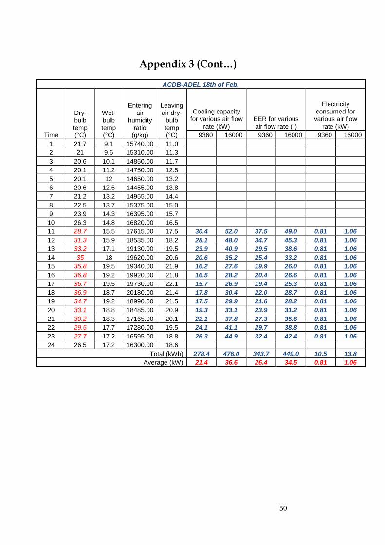
50
Appendix 3 (Cont…)
ACDB-ADEL 18th of Feb.
Time
Dry-bulb temp (°C)
Wet-bulb temp (°C)
Entering air
humidity ratio
(g/kg)
Leaving air dry-
bulb temp (°C)
Cooling capacity for various air flow
rate (kW) EER for various air flow rate (-)
Electricity consumed for
various air flow rate (kW)
9360 16000 9360 16000 9360 16000
1 21.7 9.1 15740.00 11.0
2 21 9.6 15310.00 11.3
3 20.6 10.1 14850.00 11.7
4 20.1 11.2 14750.00 12.5
5 20.1 12 14650.00 13.2
6 20.6 12.6 14455.00 13.8
7 21.2 13.2 14955.00 14.4
8 22.5 13.7 15375.00 15.0
9 23.9 14.3 16395.00 15.7
10 26.3 14.8 16820.00 16.5
11 28.7 15.5 17615.00 17.5 30.4 52.0 37.5 49.0 0.81 1.06
12 31.3 15.9 18535.00 18.2 28.1 48.0 34.7 45.3 0.81 1.06
13 33.2 17.1 19130.00 19.5 23.9 40.9 29.5 38.6 0.81 1.06
14 35 18 19620.00 20.6 20.6 35.2 25.4 33.2 0.81 1.06
15 35.8 19.5 19340.00 21.9 16.2 27.6 19.9 26.0 0.81 1.06
16 36.8 19.2 19920.00 21.8 16.5 28.2 20.4 26.6 0.81 1.06
17 36.7 19.5 19730.00 22.1 15.7 26.9 19.4 25.3 0.81 1.06
18 36.9 18.7 20180.00 21.4 17.8 30.4 22.0 28.7 0.81 1.06
19 34.7 19.2 18990.00 21.5 17.5 29.9 21.6 28.2 0.81 1.06
20 33.1 18.8 18485.00 20.9 19.3 33.1 23.9 31.2 0.81 1.06
21 30.2 18.3 17165.00 20.1 22.1 37.8 27.3 35.6 0.81 1.06
22 29.5 17.7 17280.00 19.5 24.1 41.1 29.7 38.8 0.81 1.06
23 27.7 17.2 16595.00 18.8 26.3 44.9 32.4 42.4 0.81 1.06
24 26.5 17.2 16300.00 18.6
Total (kWh) 278.4 476.0 343.7 449.0 10.5 13.8
Average (kW) 21.4 36.6 26.4 34.5 0.81 1.06
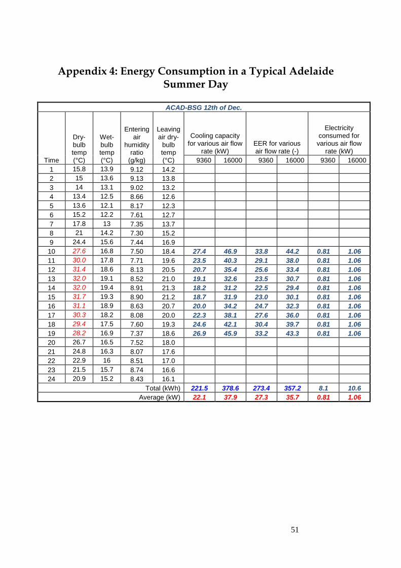
51
Appendix 4: Energy Consumption in a Typical Adelaide Summer Day
ACAD-BSG 12th of Dec.
Time
Dry-bulb temp (°C)
Wet-bulb temp (°C)
Entering air
humidity ratio
(g/kg)
Leaving air dry-
bulb temp (°C)
Cooling capacity for various air flow
rate (kW) EER for various air flow rate (-)
Electricity consumed for
various air flow rate (kW)
9360 16000 9360 16000 9360 16000
1 15.8 13.9 9.12 14.2
2 15 13.6 9.13 13.8
3 14 13.1 9.02 13.2
4 13.4 12.5 8.66 12.6
5 13.6 12.1 8.17 12.3
6 15.2 12.2 7.61 12.7
7 17.8 13 7.35 13.7
8 21 14.2 7.30 15.2
9 24.4 15.6 7.44 16.9
10 27.6 16.8 7.50 18.4 27.4 46.9 33.8 44.2 0.81 1.06
11 30.0 17.8 7.71 19.6 23.5 40.3 29.1 38.0 0.81 1.06
12 31.4 18.6 8.13 20.5 20.7 35.4 25.6 33.4 0.81 1.06
13 32.0 19.1 8.52 21.0 19.1 32.6 23.5 30.7 0.81 1.06
14 32.0 19.4 8.91 21.3 18.2 31.2 22.5 29.4 0.81 1.06
15 31.7 19.3 8.90 21.2 18.7 31.9 23.0 30.1 0.81 1.06
16 31.1 18.9 8.63 20.7 20.0 34.2 24.7 32.3 0.81 1.06
17 30.3 18.2 8.08 20.0 22.3 38.1 27.6 36.0 0.81 1.06
18 29.4 17.5 7.60 19.3 24.6 42.1 30.4 39.7 0.81 1.06
19 28.2 16.9 7.37 18.6 26.9 45.9 33.2 43.3 0.81 1.06
20 26.7 16.5 7.52 18.0
21 24.8 16.3 8.07 17.6
22 22.9 16 8.51 17.0
23 21.5 15.7 8.74 16.6
24 20.9 15.2 8.43 16.1
Total (kWh) 221.5 378.6 273.4 357.2 8.1 10.6
Average (kW) 22.1 37.9 27.3 35.7 0.81 1.06
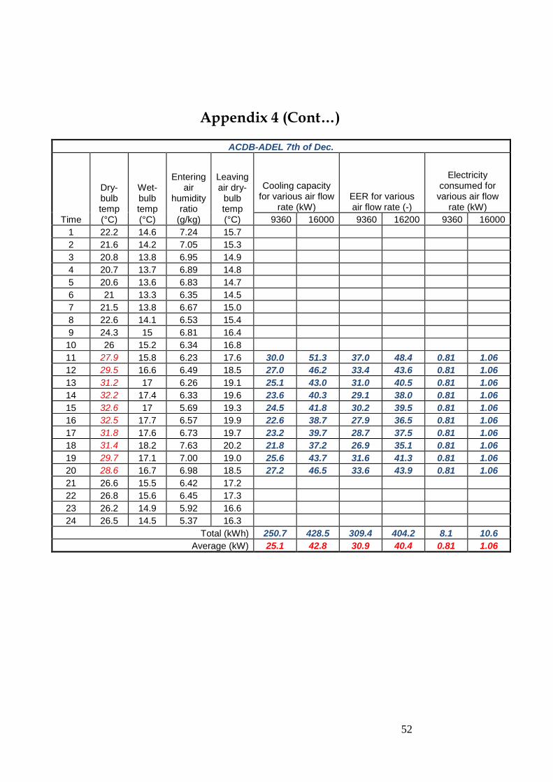
52
Appendix 4 (Cont…)
ACDB-ADEL 7th of Dec.
Time
Dry-bulb temp (°C)
Wet-bulb temp (°C)
Entering air
humidity ratio
(g/kg)
Leaving air dry-
bulb temp (°C)
Cooling capacity for various air flow
rate (kW) EER for various air flow rate (-)
Electricity consumed for
various air flow rate (kW)
9360 16000 9360 16200 9360 16000
1 22.2 14.6 7.24 15.7
2 21.6 14.2 7.05 15.3
3 20.8 13.8 6.95 14.9
4 20.7 13.7 6.89 14.8
5 20.6 13.6 6.83 14.7
6 21 13.3 6.35 14.5
7 21.5 13.8 6.67 15.0
8 22.6 14.1 6.53 15.4
9 24.3 15 6.81 16.4
10 26 15.2 6.34 16.8
11 27.9 15.8 6.23 17.6 30.0 51.3 37.0 48.4 0.81 1.06
12 29.5 16.6 6.49 18.5 27.0 46.2 33.4 43.6 0.81 1.06
13 31.2 17 6.26 19.1 25.1 43.0 31.0 40.5 0.81 1.06
14 32.2 17.4 6.33 19.6 23.6 40.3 29.1 38.0 0.81 1.06
15 32.6 17 5.69 19.3 24.5 41.8 30.2 39.5 0.81 1.06
16 32.5 17.7 6.57 19.9 22.6 38.7 27.9 36.5 0.81 1.06
17 31.8 17.6 6.73 19.7 23.2 39.7 28.7 37.5 0.81 1.06
18 31.4 18.2 7.63 20.2 21.8 37.2 26.9 35.1 0.81 1.06
19 29.7 17.1 7.00 19.0 25.6 43.7 31.6 41.3 0.81 1.06
20 28.6 16.7 6.98 18.5 27.2 46.5 33.6 43.9 0.81 1.06
21 26.6 15.5 6.42 17.2
22 26.8 15.6 6.45 17.3
23 26.2 14.9 5.92 16.6
24 26.5 14.5 5.37 16.3
Total (kWh) 250.7 428.5 309.4 404.2 8.1 10.6
Average (kW) 25.1 42.8 30.9 40.4 0.81 1.06
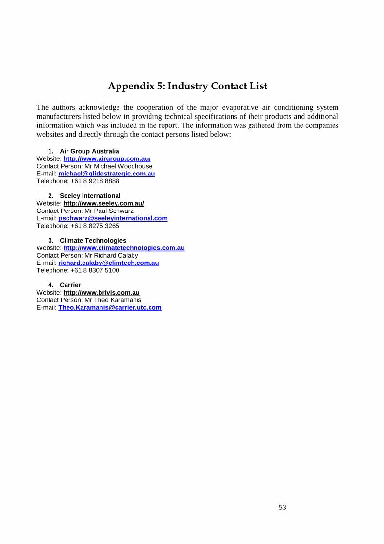
53
Appendix 5: Industry Contact List
The authors acknowledge the cooperation of the major evaporative air conditioning system
manufacturers listed below in providing technical specifications of their products and additional
information which was included in the report. The information was gathered from the companies‘
websites and directly through the contact persons listed below:
1. Air Group Australia
Website: http://www.airgroup.com.au/ Contact Person: Mr Michael Woodhouse E-mail: [email protected] Telephone: +61 8 9218 8888
2. Seeley International Website: http://www.seeley.com.au/ Contact Person: Mr Paul Schwarz E-mail: [email protected] Telephone: +61 8 8275 3265
3. Climate Technologies Website: http://www.climatetechnologies.com.au Contact Person: Mr Richard Calaby E-mail: [email protected] Telephone: +61 8 8307 5100
4. Carrier Website: http://www.brivis.com.au Contact Person: Mr Theo Karamanis E-mail: [email protected]

54
Appendix 6: Glossary of terms
Air change: the replacement of a quantity of air in a volume within a given period of time. This
is expressed in number of changes per hour. If a house has 1 air change per hour, all the air in the
house will be replaced in a 1-hour period.
Air change per hour (ach): a unit that denotes the number of times a house exchanges its entire
volume of air with outside air in an hour.
Air Flow: Measures the flow of air, often in CFMs. This should be carefully balanced to ensure
maximum cooling efficiency and optimal operation.
Air, ambient: surrounding air.
Air, saturated: moist air in which the partial pressure of water vapour equals the vapour
pressure of water at the existing temperature. This occurs when dry air and saturated water
vapour co-exist at the same dry-bulb temperature.
Air, standard: dry air at a pressure of 101.325 kPa at a temperature of exactly 20 °C. Under
these conditions, the density is 1.2041 kg/m3.
ASHRAE: The American Society of Heating Air Conditioning and Refrigeration Engineers.
Bleed Rate: The flow rate of water leaving the evaporative cooler sump, and which is replaced
with cleaner inlet water. Used to control the build-up of dust and minerals in the sump water.
CFM: Cubic feet per minute. Typical English measurement for the flow rate from a fan.
Collector, solar: a device for capturing solar energy, ranging from ordinary windows to
complex mechanical devices.
Combustion air: the air required to provide adequate oxygen for fuel burning appliances in the
building. The term ‗combustion air‘ is often used to refer to the total air requirement of a fuel
burning appliance including both air to support the combustion process and air to provide
chimney draft (dilution air).
Conditioned space: Space within a building which is provided with positive heat and/or cool
supply, or which has heated and/or cooled air or surfaces, or where required, with humidification
or dehumidification means, so as to be capable of maintaining a space condition falling within
the comfort zone set forth in the ASHRAE Handbooks.
Conductivity: the quantity of heat that will flow through one square metre of material, one
Metre thick, in one second, when there is a temperature difference of 1ºC between its surfaces.
Cooling Capacity: A measure of the ability of a unit to remove heat from an enclosed space.
COP: Coefficient of Performance of a heat pump means the ratio of the rate of useful heat
output delivered by the complete heat pump unit (exclusive of supplementary heating) to the
corresponding rate of energy input, in consistent units and under operating conditions.
Cooling Pads: Otherwise known as cool media. Pads that are found in an evaporative cooler;
water is directed onto these pads and fresh, outside air is pulled through the moist pads where it
is cooled by evaporation and circulated through an area.
Density: the mass of a substance, expressed in kilograms per cubic metre.
Design conditions: Specified environmental conditions, such as temperature and light intensity,
required to be produced and maintained by a system and under which the system must operate.
Direct radiation: the component of solar radiation that comes directly from the sun without
being diffused or reflected.
Dry bulb temperature: the temperature of a gas of mixture or gases indicated by an accurate
thermometer after correction for radiation.
Duct: A main trunk or branch round or rectangular tube, normally installed for air distribution of
heating and/or cooling air conditioning systems and which depends on a blower for air
circulation.
Ducted system: A ducted system is one that provides cooling to multiple rooms through a series
of ducts, which are usually installed in the roof.

55
Energy: The capacity for doing work taking a number of forms that may be transformed from
one into another, such as thermal (heat), mechanical (work), electrical and chemical in
customary units, measured in kilowatt-hours (kWh) or British thermal units (Btu).
Energy efficiency: The more efficient use of energy in order to reduce economic costs and
environmental impacts. Using less energy/electricity to perform the same function.
Energy efficiency Ratio (EER): The ratio of net equipment cooling capacity in Btu/h to total
rate of electric input in watts (W) under designated operating conditions. If the output capacity in
Btu/h is converted to watts (to create consistent units) the result is equal to the cooling COP
(EER X 3.41 = COP.)
Energy Star: Energy Star qualified appliances and air conditioners meet strict energy efficiency
guidelines set by the EPA and the U.S. Department of Energy and use at least 10% less energy
than conventional models.
Evaporation: phase change of a material from liquid to vapour at a temperature below the
boiling point of the liquid. Cooling occurs during the process of evaporation.
Evaporative Air-cooling: Lowering of the dry-bulb temperature as air moves over a water
surface.
Evaporative cooling: A heat removal process in which water vapour is added to air, increasing
its humidity while lowering its temperature. The total amount of heat in the air stays constant,
but is transferred from sensible heat in the air to latent heat in the moisture. In the process of
changing from liquid to vapour (evaporating), the water must absorb large amount of heat.
Evaporative cooling, Direct: a cooling process where the warm and dry air moves through a
wetted medium to evaporate moisture in the air. The cool humid air is then used to cool a place.
Evaporative cooling, Indirect: a cooling process where the evaporative process is remote from
the conditioned space. The cooled air is then used to lower the temperature of the building
surface, such as in a roof spray, or is passed through a heat exchanger to cool indoor air. The
indirect process has the advantage of lowering temperatures without adding humidity to the air,
thus extending the climate conditions and regions in which evaporate cooling is effective.
Geothermal: Literally, the heat of the earth. Where this heat occurs close to the earth's surface,
and is able to maintain a temperature in the surrounding rock or water at or above 150 degrees C,
it may be tapped to drive steam turbines.
Heat exchanger: a device usually consisting of a coiled arrangement of metal tubing used to
transfer heat through the tube walls from one fluid to another.
Heat pump: a thermodynamic device that transfers heat from one medium to another; the first
medium cools while the second warms up.
Human thermal comfort: Human thermal comfort is defined by ASHRAE as the state of mind
that expresses satisfaction with the surrounding environment (ASHRAE Standard 55).
Humidity: water vapour within a given space.
HVAC: mechanical system for heating, ventilating and air-conditioning that controls
temperature, humidity, and air quality.
Inverter: An "inverter" system is one with a variable speed compressor. This means that the air
conditioner can adjust its power output to suit the amount of cooling required at the time, which
usually results in an energy saving.
Kilowatt (kW): A kilowatt (abbreviation: kW) is 1000 watts and is a measure of cooling
capacity. It is also a measure of electrical input.
Kilowatt hour (kWh): A kilowatt hour (abbreviation: kWh) is the common unit of measure for
electrical energy consumption over time.
Multi-split system: A multi-split system is a split system that has a single outdoor unit
connected to multiple indoor units. It is possible to operate these systems independent of each
other or at the same time. These systems are best suited to cooling multiple rooms.
56
Portable air conditioner: Portable air conditioners are usually small in capacity, and may be
either refrigerated or evaporative. Normally the only installation they require is to be plugged
into an electrical outlet - if this is the case, they can be used without needing a licensed
contractor to install them. Some portable air conditioners may require hoses to be run to an
outside space (typically through a window) for water to drain and/or for heat to escape, as a
result they may not be suited to all applications.
Pressure: the normal force exerted by a homogenous liquid or gas, per unit area, on the wall of
container.
Pressure difference: the difference in pressure between the volume of air enclosed by the
building envelope and the air surrounding the envelope.
Psychrometric Chart: Graphic representation of the properties of moist air. Gives the readings
of DB, WB, and dew point temperatures, enthalpy, specific volume, RH, and water vapour
content. Enables one to graphically see cause and effect when the quality of air is changed.
Refrigerant: The working fluid in a vapour compression refrigerated air-conditioner.
Refrigerated system: A refrigerated system uses a refrigerant to take heat from the indoor space
and reject it outside.
Relative humidity: the percentage of water vapour in the atmosphere relative to the maximum
amount of water vapour that can be held by the air at a given temperature.
Reverse cycle: A reverse cycle system is one that can change modes to provide either heating or
cooling.
Saturation Effectiveness: A ratio of the change in dry-bulb temperature divided by the
difference between the outside air dry-bulb and the wet-bulb temperature. Used to predict the
discharge performance of an evaporative air cooler.
Seasonal Energy Efficiency Ratio, SEER: Air conditioners are given a SEER rating by the
industry. The value represents the average cooling output per unit input electrical energy
consumed during a cooling season.The higher the SEER rating, the greater the efficiency. An air
conditioning unit that has a rating of SEER 10 is 25% more efficient than one with a rating of 8.0.
Specific heat: a measure of the ability of a material to store heat. Specifically, the quantity of
heat required to raise the temperature of unit mass of a substance by one degree. (kJ/kg °C ).
Vapour Compression: Mechanical refrigeration that uses a refrigerant i.e. chilled water or
direct expansion (DX) of the refrigerant working fluid.
Variable Speed Drive (VSD): A device which when added to a device like a centrifugal fan or a
pump, can control the speed and output of the device. Variable speed drives are often referred to
as variable frequency drive (VFD) which is a common method of controlling fan speed.
Ventilation: The process of supplying or removing air by natural or mechanical means to or
from any space. Such air may or may not have been conditioned.
Ventilation (natural): air flow through and within a space stimulated by either the distribution
of pressure gradients around a building, or thermal forces caused by temperature gradients
between indoor and outdoor air.
Watt (W): a measure of power commonly used to express heat loss or heat gain, or to specify
electrical equipment. It is the power required to produce energy at the rate of one joule per
second.
Wet-bulb temperature: the air temperature measured using a thermometer with a wetted bulb
moved rapidly through the air to promote evaporation. The evaporating moisture and changing
phase lowers the temperature measured relative to that measured with a dry bulb. Wet bulb
temperature accounts for the effects of moisture in the air. It can be used along with the dry-bulb
temperature on a psychrometric chart to determine relative humidity.