technical service guide - applianceassistant.com · g ge consumer service training technical...
TRANSCRIPT
gGE Consumer Service Training
TECHNICAL SERVICE GUIDE
NEW 30" XL44™ SERIES RANGESFEATURING TRUETEMPTM COOKING
gPUB # 31-9008
MODEL SERIES:
JGBP90 AJGBP86 AJGBP85 AJGBP79 AJGBP35 AJGBP30 AJGBP26 A

CAUTION To avoid personal injury while servicing this unit, disconnect power before servicing. If grounding wires, screws, straps, clips, nuts, or washers used to complete a path to ground are removed for service, they must be returned to their original position and properly fastened.
!IMPORTANT SAFETY NOTICE
The information in this service guide is intended for use by individuals possessing adequate backgrounds of electrical, electronic and mechanical experience. Any attempt to repair a major appliance may result in personal injury and property damage. The manufacturer or seller cannot be responsible for the interpretation of this information, nor can it assume any liability in connection with it's use.
About This Service Guide
Outstanding New Features
New Features / Design
Features and Specifications
Cook Top / Surface Burners
Conversion & Orifice information
Control Panel Access
ERC III Special Features
True Temp™ Design
ERC On-Board Diagnostics
Lock Motor Circuit & Diagnostics
Schematics / Strip Circuits / Diagnostics
Illustrated Parts Information
Flow Chart - Bake / Broil Circuit
3-6
2
7
8-9
10
11-12
Table of Contents
13
14-15
16
17-18
19
20-24
25-30
31
– 1 –
TECHNICAL SERVICE GUIDENEW 30" XL44™ SERIES RANGES
FEATURING TRUE TEMP™ COOKING

Black on blackScratch-resistant glass backguardQuickSet V oven controls with digipad entry; auto oven shut-off with override; start pad; delay clean option; and self-clean cool down time displayFluorescent cooktop night lightFrameless glass oven door with Big View windowSure Grip handleDesigner-style control knobsOne-piece upswept porcelain-enameled cooktopSquare deluxe cast grates with rubber feetOne-piece drip pans
JGBP85EA (not shown)Almond on almond
JGBP85WEA (not shown)White on white
GE Profile™JGBP85BEA
ABOUT THIS TECHNICAL SERVICE GUIDE - FEATURED MODELThe new XL44™ series of gas ranges encompass over 40 different models. We have selected one model which covers most of the new features and designs reflected in the XL44™, 30" gas series of ranges. For model specific information, refer to the charts included in this Guide, on pages 8 & 9.
This service guide will focus primarily on the NEW changes introduced in the XL44™ series of ranges. What this guide will not cover are features, technology and serviceability that we have previously covered in prior training manuals. If you would like additional information on the XL44™ series of ranges which will not be coved in this manual, refer to the following previously issued training publications
FEATURED MODEL
– 2 –
31-0303 30" free standing ranges, 1990-91 "N" & "P" models; including XL44™ series and capacity plus models
31-1466 "V" line, XL44™ series
31-1465 Carbon monoxide measurements
PublicationNumber
Technical Training ManualTitle
XL44™: SELF-CLEANING WITH SEALED BURNERS

A FULL RANGE OF POWER
YOU DON'T COOK SPAGHETTI THE SAME WAY YOU SAUTÉ MUSHROOMS.
You don't want a sauce to boil when it's supposed to simmer. For best results,
different foods should be cooked over differing levels of heat. That's why, on GE
gas ranges, each burner has its own BTU rating. The high-output burner provides
quick heat-up and boiling—faster than the “high-power” burners found on most
gas ranges. This burner supplies the intense heat needed for the lobster pot, pasta
pan, or wok. At the other end of the spectrum is the ultra-low simmer burner. The
simmer burner provides precise temperature control and the consistently gentle
heating required for delicate foods or sauces. Between these extremes are two all-
purpose burners with a mid-range of power, for cooking over medium heat. It all
adds up to a full range of power, to help you control cooking with a greater degree
of precision. And GE makes it so easy. Simply choose the burner and heat level best
suited to the cooking—Maximum output, Precise simmer, or virtually any point
in between.
When it comes to BTUs, the GE gasrange delivers the highs, the lows andeverything in between.
– 3 –
BakingTemp.
Other Leading Manufacturers' AverageAmana, Magic Chef, Whirlpool, Maytag, KitchenAid, Tappan
GE TrueTemp™
Out-performs theother leading brands.
Maytag
Whirlpool
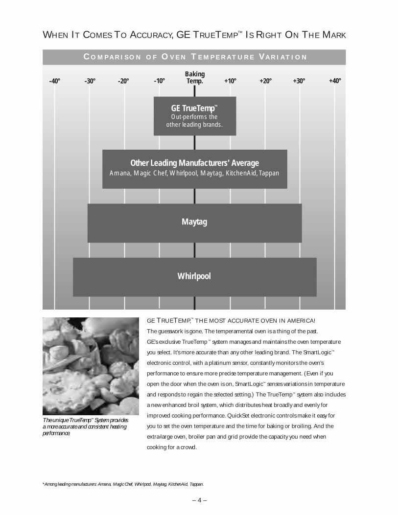
-40° -30° -20° -10° +10° +20° +30° +40°
GE TRUETEMP,™ THE MOST ACCURATE OVEN IN AMERICA!
The guesswork is gone. The temperamental oven is a thing of the past.
GE's exclusive TrueTemp™ system manages and maintains the oven temperature
you select. It's more accurate than any other leading brand. The SmartLogic™
electronic control, with a platinum sensor, constantly monitors the oven's
performance to ensure more precise temperature management. (Even if you
open the door when the oven is on, SmartLogic™ senses variations in temperature
and responds to regain the selected setting.) The TrueTemp™ system also includes
a new enhanced broil system, which distributes heat broadly and evenly for
improved cooking performance. QuickSet electronic controls make it easy for
you to set the oven temperature and the time for baking or broiling. And the
extra-large oven, broiler pan and grid provide the capacity you need when
cooking for a crowd.
WHEN IT COMES TO ACCURACY, GE TRUETEMP™ IS RIGHT ON THE MARK
The unique TrueTemp™ System provides a more accurate and consistent heating performance.
*Among leading manufacturers: Amana, Magic Chef, Whirlpool, Maytag, KitchenAid, Tappan.
C O M P A R I S O N O F O V E N T E M P E R A T U R E VA R I A T I O N
– 4 –
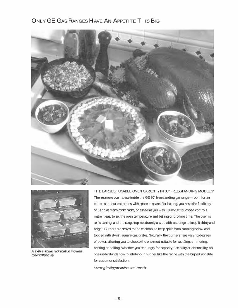
ONLY GE GAS RANGES HAVE AN APPETITE THIS BIG
THE LARGEST USABLE OVEN CAPACITY IN 30" FREE-STANDING MODELS*
There's more oven space inside the GE 30" free-standing gas range—room for an
entree and four casseroles, with space to spare. For baking, you have the flexibility
of using as many as six racks, or as few as you wish. QuickSet touchpad controls
make it easy to set the oven temperature and baking or broiling time. The oven is
self-cleaning, and the range top needs only a wipe with a sponge to keep it shiny and
bright. Burners are sealed to the cooktop, to keep spills from running below, and
topped with stylish, square cast grates. Naturally, the burners have varying degrees
of power, allowing you to choose the one most suitable for sautéing, simmering,
heating or boiling. Whether you're hungry for capacity, flexibility or cleanability, no
one understands how to satisfy your hunger like the range with the biggest appetite
for customer satisfaction.
*Among leading manufacturers' brands.
A sixth embossed rack position increasescooking flexibility.
– 5 –

THE FIRST THING YOU NOTICE IS THE STRIKING DESIGN. A bold,
geometric pattern tops off this GE gas range, but there's more to the cooktop than
its beauty. The big story here is convenience. The cast-iron platform, made up of
two interlocking grates, provides a flat surface for cooking and meal
preparation. To switch cookware from one burner to another, you don't have to
lift the pans, perform a balancing act, and risk spilling the contents. Just slide the
pans from burner to burner. The cooktop design allows you to easily rotate pots
and pans as needed—and it's especially helpful when you're handling a larger pot
of bubbling soup or stew. The space in the center can be used for preparing foods
or for transferring cooked foods to serving dishes. We've even simplified clean-up
for you, by making the grates easy to uncouple and remove for washing. Since
Americans do most of their cooking on top of the range, it just makes sense to
build convenience into the cooktop design. That's the way we see it. And that's the
way we've done it, “plain” and simple.
WE'VE PUT A NEW SPIN ON A GRATE TOP
GE's professional grate lets you slide hotpans on and off burners without lifting,balancing or spilling.
– 6 –
12,000 BTUNEW FOR ̀ 982 MAX OUTPUTBURNERS
5,000 BTU
NOTE:All four surface burnershave 270
o rotation
OFF LITE HI
LOW
NEW FOR `98BIG VIEW TRUETEMP
TM
ERC III
9,500 BTUALL PURPOSESEALED BURNER
12,000 BTUNEW FOR ̀ 98 - 2 MAX OUTPUTBURNERS
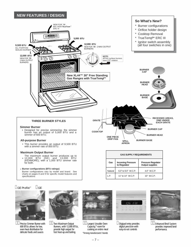
NEW FEATURES / DESIGN
Gas Incoming Pressure Pressure Regulator to Regulator Output supplies
Natural 6.0" to 9.0" W.C.P. 4.0" W.C.P.
L.P. 11" to 14" W.C.P. 10" W.C.P.
GAS SUPPLY REQUIREMENTS
So What's New?* Burner configurations* Orifice holder design* Cooktop Removal* TrueTemp™ ERC III* Ignitor switch assembly (all four switches in one)
BURNERCAP
BURNERBASE
BURNERHEAD
RECESSED AREAS,ONE UNDEREACH GRATE
BURNER CAP
BURNER HEAD
BURNER BASESPILLAPRON
ONE PIECEDRIP PAN
COOKTOP
GRATE
Designed for precise simmering; the simmer burner has an output of 5,000 BTU and a simmer of 600 BTU.
This burner provides an output of 9,500 BTU with a simmer rate of 850 BTU.
The maximum output burner produces up to 12,000 BTU (GE) and 13,000 BTU (KENMORE), with a 1,000 BTU simmer rate for both.
Simmer Burner
All-purpose Burner
Maximum Output Burner
THREE BURNER STYLES
Burner configurations (BTU ratings)Burner configurations vary by model and brand. See charts on pages 8 and 9 for specific model features and specifications
*
New XL44™ 30" Free StandingGas Ranges with TrueTemp™
– 7 –
z Digipad entry provides digital precision with easy-to-set controls
z z Largest Useable OvenCapacity,* room forcooking an entire meal
*Among manufacturers' brands
z z Two Maximum OutputBurners, with 12,000 BTUs,provide high output for fast heat-up and boiling
z z Precise Simmer Burner with600 BTUs allows for low,even heat distribution fordelicate foods and sauces
z z Enhanced Broil System provides improved broilperformance
z GE Profile™ z GE
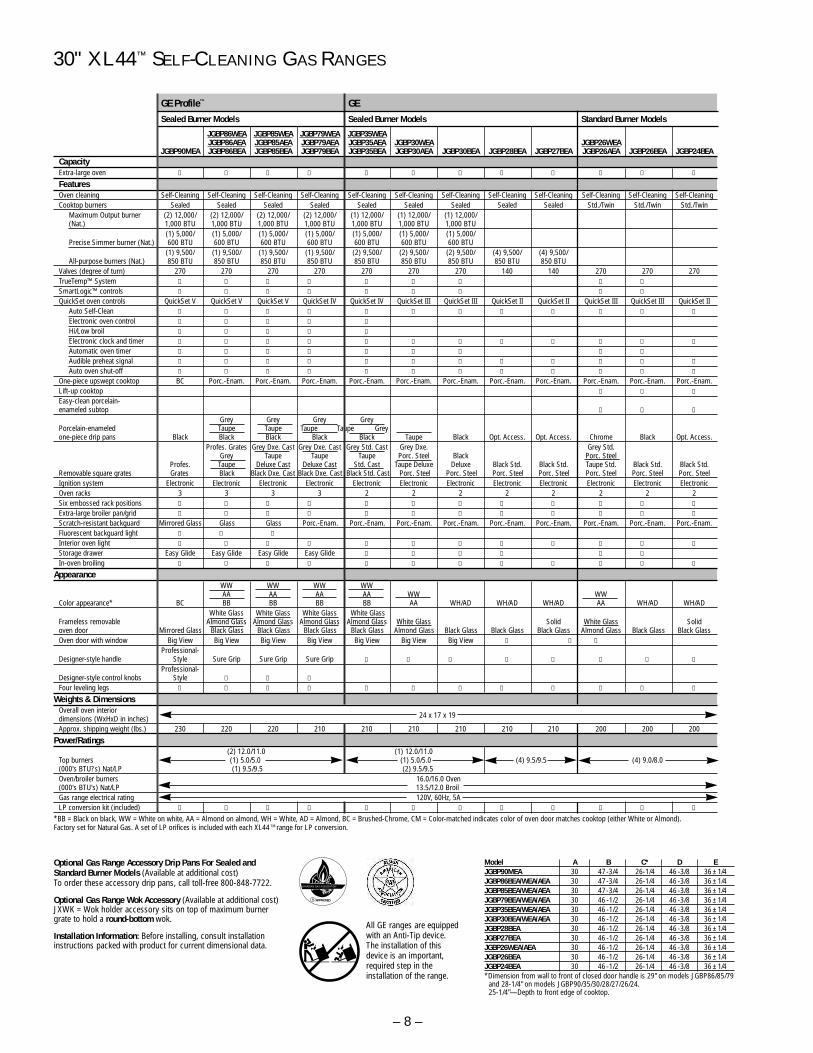
30" XL44™ SELF-CLEANING GAS RANGES
Optional Gas Range Accessory Drip Pans For Sealed and Standard Burner Models (Available at additional cost)To order these accessory drip pans, call toll-free 800-848-7722.
Optional Gas Range Wok Accessory (Available at additional cost) JXWK = Wok holder accessory sits on top of maximum burnergrate to hold a round-bottom wok.
Installation Information: Before installing, consult installationinstructions packed with product for current dimensional data.
CANADIAN GAS ASSOCIATION
R APPROVED
JGBP86WEA JGBP85WEA JGBP79WEA JGBP35WEAJGBP86AEA JGBP85AEA JGBP79AEA JGBP35AEA JGBP30WEA JGBP26WEA
JGBP90MEA JGBP86BEA JGBP85BEA JGBP79BEA JGBP35BEA JGBP30AEA JGBP30BEA JGBP28BEA JGBP27BEA JGBP26AEA JGBP26BEA JGBP24BEACapacityExtra-large oven l l l l l l l l l l l l
FeaturesOven cleaning Self-Cleaning Self-Cleaning Self-Cleaning Self-Cleaning Self-Cleaning Self-Cleaning Self-Cleaning Self-Cleaning Self-Cleaning Self-Cleaning Self-Cleaning Self-CleaningCooktop burners Sealed Sealed Sealed Sealed Sealed Sealed Sealed Sealed Sealed Std./Twin Std./Twin Std./Twin
Maximum Output burner (2) 12,000/ (2) 12,000/ (2) 12,000/ (2) 12,000/ (1) 12,000/ (1) 12,000/ (1) 12,000/(Nat.) 1,000 BTU 1,000 BTU 1,000 BTU 1,000 BTU 1,000 BTU 1,000 BTU 1,000 BTU
(1) 5,000/ (1) 5,000/ (1) 5,000/ (1) 5,000/ (1) 5,000/ (1) 5,000/ (1) 5,000/Precise Simmer burner (Nat.) 600 BTU 600 BTU 600 BTU 600 BTU 600 BTU 600 BTU 600 BTU
(1) 9,500/ (1) 9,500/ (1) 9,500/ (1) 9,500/ (2) 9,500/ (2) 9,500/ (2) 9,500/ (4) 9,500/ (4) 9,500/All-purpose burners (Nat.) 850 BTU 850 BTU 850 BTU 850 BTU 850 BTU 850 BTU 850 BTU 850 BTU 850 BTU
Valves (degree of turn) 270 270 270 270 270 270 270 140 140 270 270 270TrueTemp™ System l l l l l l l l l
SmartLogic™ controls l l l l l l l l l
QuickSet oven controls QuickSet V QuickSet V QuickSet V QuickSet IV QuickSet IV QuickSet III QuickSet III QuickSet II QuickSet II QuickSet III QuickSet III QuickSet IIAuto Self-Clean l l l l l l l l l l l l
Electronic oven control l l l l l
Hi/Low broil l l l l l
Electronic clock and timer l l l l l l l l l l l l
Automatic oven timer l l l l l l l l l
Audible preheat signal l l l l l l l l l l l l
Auto oven shut-off l l l l l l l l l l l l
One-piece upswept cooktop BC Porc.-Enam. Porc.-Enam. Porc.-Enam. Porc.-Enam. Porc.-Enam. Porc.-Enam. Porc.-Enam. Porc.-Enam. Porc.-Enam. Porc.-Enam. Porc.-Enam.Lift-up cooktop l l l
Easy-clean porcelain-enameled subtop l l l
Grey Grey Grey GreyPorcelain-enameled Taupe Taupe Taupe Taupe Greyone-piece drip pans Black Black Black Black Black Taupe Black Opt. Access. Opt. Access. Chrome Black Opt. Access.
Profes. Grates Grey Dxe. Cast Grey Dxe. Cast Grey Std. Cast Grey Dxe. Grey Std. Grey Taupe Taupe Taupe Porc. Steel Black Porc. Steel
Profes. Taupe Deluxe Cast Deluxe Cast Std. Cast Taupe Deluxe Deluxe Black Std. Black Std. Taupe Std. Black Std. Black Std.Removable square grates Grates Black Black Dxe. Cast Black Dxe. Cast Black Std. Cast Porc. Steel Porc. Steel Porc. Steel Porc. Steel Porc. Steel Porc. Steel Porc. SteelIgnition system Electronic Electronic Electronic Electronic Electronic Electronic Electronic Electronic Electronic Electronic Electronic ElectronicOven racks 3 3 3 3 2 2 2 2 2 2 2 2Six embossed rack positions l l l l l l l l l l l l
Extra-large broiler pan/grid l l l l l l l l l l l l
Scratch-resistant backguard Mirrored Glass Glass Glass Porc.-Enam. Porc.-Enam. Porc.-Enam. Porc.-Enam. Porc.-Enam. Porc.-Enam. Porc.-Enam. Porc.-Enam. Porc.-Enam.Fluorescent backguard light l l l
Interior oven light l l l l l l l l l l l l
Storage drawer Easy Glide Easy Glide Easy Glide Easy Glide l l l l l l
In-oven broiling l l l l l l l l l l l l
AppearanceWW WW WW WWAA AA AA AA WW WW
Color appearance* BC BB BB BB BB AA WH/AD WH/AD WH/AD AA WH/AD WH/ADWhite Glass White Glass White Glass White Glass
Frameless removable Almond Glass Almond Glass Almond Glass Almond Glass White Glass Solid White Glass Solid oven door Mirrored Glass Black Glass Black Glass Black Glass Black Glass Almond Glass Black Glass Black Glass Black Glass Almond Glass Black Glass Black GlassOven door with window Big View Big View Big View Big View Big View Big View Big View l l l
Professional-Designer-style handle Style Sure Grip Sure Grip Sure Grip l l l l l l l l
Professional-Designer-style control knobs Style l l l
Four leveling legs l l l l l l l l l l l l
Weights & DimensionsOverall oven interior dimensions (WxHxD in inches) 24 x 17 x 19
Approx. shipping weight (lbs.) 230 220 220 210 210 210 210 210 210 200 200 200
Power/Ratings(2) 12.0/11.0 (1) 12.0/11.0
Top burners (1) 5.0/5.0 (1) 5.0/5.0 (4) 9.5/9.5 (4) 9.0/8.0(000's BTU?s) Nat/LP (1) 9.5/9.5 (2) 9.5/9.5Oven/broiler burners 16.0/16.0 Oven(000's BTU's) Nat/LP 13.5/12.0 BroilGas range electrical rating 120V, 60Hz, 5ALP conversion kit (included) l l l l l l l l l l l l
*BB = Black on black, WW = White on white, AA = Almond on almond, WH = White, AD = Almond, BC = Brushed-Chrome, CM = Color-matched indicates color of oven door matches cooktop (either White or Almond).Factory set for Natural Gas. A set of LP orifices is included with each XL44 TM range for LP conversion.
Sealed Burner Models Sealed Burner Models Standard Burner Models
Model A B C* D EJGBP90MEA 30 47-3/4 26-1/4 46 -3/8 36 ± 1/4JGBP86BEA/WEA/AEA 30 47-3/4 26-1/4 46 -3/8 36 ± 1/4JGBP85BEA/WEA/AEA 30 47-3/4 26-1/4 46 -3/8 36 ± 1/4JGBP79BEA/WEA/AEA 30 46 -1/2 26-1/4 46 -3/8 36 ± 1/4JGBP35BEA/WEA/AEA 30 46 -1/2 26-1/4 46 -3/8 36 ± 1/4JGBP30BEA/WEA/AEA 30 46 -1/2 26-1/4 46 -3/8 36 ± 1/4JGBP28BEA 30 46 -1/2 26-1/4 46 -3/8 36 ± 1/4JGBP27BEA 30 46 -1/2 26-1/4 46 -3/8 36 ± 1/4JGBP26WEA/AEA 30 46 -1/2 26-1/4 46 -3/8 36 ± 1/4JGBP26BEA 30 46 -1/2 26-1/4 46 -3/8 36 ± 1/4JGBP24BEA 30 46 -1/2 26-1/4 46 -3/8 36 ± 1/4*Dimension from wall to front of closed door handle is 29" on models JGBP86/85/79
and 28-1/4" on models JGBP90/35/30/28/27/26/24. 25-1/4"—Depth to front edge of cooktop.
All GE ranges are equippedwith an Anti-Tip device. The installation of thisdevice is an important,required step in the installation of the range.
GE Profile™ GE
– 8 –
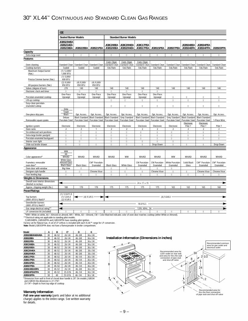
30" XL44™ CONTINUOUS AND STANDARD CLEAN GAS RANGES
A
B
C
D
E
24
30
8
4
92
2-1/2
Recommended area forthru the floor connection
of pipe stub and shut-off valve
Recommended area for 120V outlet on rear walland area for thru the wallconnection of pipe stub
and shut-off valve
Recommended common area for gas outlet and electrical outlet
Model A B C* D EJGBS23BEA/WEA/AEA 30 46-1/2 26-1/4 46 -3/8 36 ± 1/4JGBS22BEA 30 46-1/2 26-1/4 46 -3/8 36 ± 1/4JGBS21PEA 30 46-1/2 26-1/4 46 -3/8 36 ± 1/4JGBC20BEA 30 46-1/2 26-1/4 46 -3/8 36 ± 1/4JGBS20BEA 30 46-1/2 26-1/4 46 -3/8 36 ± 1/4JGBC20WEA 30 46-1/2 26-1/4 46 -3/8 36 ± 1/4JGBS20WEA 30 46-1/2 26-1/4 46 -3/8 36 ± 1/4JGBC17PEA 30 46-1/2 26-1/4 46 -1/4 36 ± 1/4JGBS17PEA 30 46-1/2 26-1/4 46 -1/4 36 ± 1/4JGBS15PEA 30 46-1/2 26-1/4 46 -1/4 36 ± 1/4JGBS07PEA 30 45-1/2 26-1/4 46 -1/4 36 ± 1/4JGBS04BEA/BPA 30 45-1/2 26-1/4 46 -3/8 36 ± 1/4JGBS04PEA/PPA 30 45-1/2 25-5/16 46 -1/4 36 ± 1/4JGBS03PPA 30 40 25-5/16 46 -1/4 36 ± 1/4*Dimension from wall to front of closed door handle is 29". On models JGBS04and JGBS03 the dimension is 27-7/16". 25-1/4"—Depth to front top edge of cooktop
Sealed Burner Models Standard Burner Models
Installation Information (Dimensions in inches)
GE
Warranty Information Full one-year warranty (parts and labor at no additionalcharge) applies to the entire range. See written warrantyfor details.
JGBS23WEAJGBS23AEA JGBC20BEA JGBC20WEA JGBC17PEA JGBS04BEA JGBS04PEAJGBS23BEA JGBS22BEA JGBS21PEA JGBS20BEA JGBS20WEA JGBS17PEA JGBS15PEA JGBS07PEA JGBS04BPA JGBS04PPA JGBS03PPA
CapacityExtra-large oven l l l l l l l l l l l
FeaturesCont. Clean Cont. Clean Cont. Clean
Oven cleaning Standard Clean Standard Clean Standard Clean Standard Clean Standard Clean Standard Clean Standard Clean Standard Clean Standard Clean Standard Clean Standard CleanCooktop burners Sealed Sealed Sealed Std./Twin Std./Twin Std./Twin Std./Twin Std./Twin Std./Twin Std./Twin Std./Twin
Maximum Output burner (1) 12,000/(Nat.) 1,000 BTU
(1) 5,000/Precise Simmer burner (Nat.) 600 BTU
(2) 9,500/ (4) 9,500/ (4) 9,500/All-purpose burners (Nat.) 850 BTU 850 BTU 850 BTU
Valves (degree of turn) 270 140 140 140 140 140 140 140 140 140 140Electronic clock and timer l l l l l l l
One-Piece One-Piece One-Piece One-Piece One-Piece One-Piece One-PiecePorcelain-enameled cooktop Upswept Upswept Upswept Upswept Upswept Upswept Upswept l l l l
Lift-up cooktop l l l l l l l l
Easy-clean porcelain-enameled subtop l l l l l l l l
GreyTaupe
One-piece drip pans Black Opt. Access. Opt. Access. Opt. Access. Opt. Access. Opt. Access. Opt. Access. Opt. Access. Opt. Access. Opt. Access. Opt. Access.Deluxe Black Standard Black Standard Black Standard Grey Standard Black Standard Black Standard Grey Standard Black Standard Black Standard
Removable square grates Porcelain Steel Porcelain Steel Porcelain Steel Porcelain Steel Porcelain Steel Porcelain Steel Porcelain Steel Porcelain Steel Porcelain Steel Porcelain Steel 1-Piece WireElectronic Electronic
Ignition system Electronic Electronic Electronic Electronic Electronic Electronic Electronic Electronic Pilot † Pilot † Pilot †Oven racks 2 2 1 2 2 2 2 2 2 2 2Six embossed rack positions l l l l l l l l l l l
Extra-large broiler pan/grid l l l l l l l l l l l
Porcelain-enameled backguard l l l l l l l l l l l
Interior oven light l l l l l l l
Slide-out broiler drawer l l l l l l Drop-Down l l l Drop-Down
AppearanceWWAA
Color appearance* WH/AD WH/AD WH/AD WH/AD WW WH/AD WH/AD WW WH/AD WH/AD WH/ADWhite Glass
Frameless removable Almond Glass CM* Porcelain- CM Porcelain- CM Porcelain- White Porcelain- Solid Black CM* Porcelain- CM* Porcelain- oven door* Black Glass Black Glass Enameled Black Glass White Glass Enameled Enameled Enameled Glass Enameled EnameledOven door with window Big View l l l l l l
Designer-style handle l l Chrome Visor l l l Chrome Visor l l Chrome Visor Chrome VisorFour leveling legs l l l l l l l l l l l
Weights & DimensionsOverall oven interior dimensions(WxHxD in inches) 24 x 17 x 19
Approx. shipping weight (lbs.) 180 170 170 175 175 175 175 165 165 165 160
Power/Ratings(1) 12.0/11.0
Top burners (1) 5.0/5.0 (4) 9.5/9.5 (4) 9.0/8.0(000's BTU's) Nat/LP (2) 9.5/9.5 Oven/broiler burners 18.0/16.5(000's BTU's) Nat/LPGas range electrical rating** 120V, 60Hz., 5ALP conversion kit (included) l l l l l l l l l l l
*WW= White on white, AA = Almond on almond, WH = White, AD = Almond, CM = Color-Matched indicates color of oven door matches cooktop (either White or Almond).**Electrical rating not applicable to standing pilot models.
†JGBS04BPA, JGBS04PPA and JGBS03PPA have standing pilot ignition.Factory set for Natural Gas. A set of LP orifices is included with each XL44 ™ range for LP conversion. Note: Model JGBS03PPA does not have a flamespreader in broiler compartment.
– 9 –
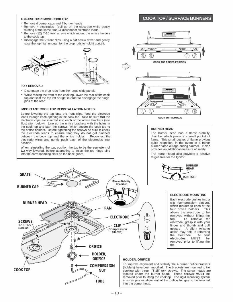
ELECTRODE MOUNTING
Each electrode pushes into a clip (compression sleeve), which mounts to each of the four orifice holders. This allows the electrode to be removed without lifting the top. To remove the electrode, grasp it with your finger and thumb and pull upward. A slight twisting action may help in removing the electrode. All four electrodes MUST be removed prior to lifting the top.
HOLDER, ORIFICE
To improve alignment and stability the 4 burner orifice brackets (holders) have been modified. The brackets are mounted to the cooktop with three "T-15" torx screws. The screw heads are located under the burner head. These screws MUST be removed prior to lifting the cooktop. The rigid mounting system ensures proper alignment of the orifice for gas to be injected into the burner head.
BURNER HEADThe burner head has a flame stability chamber which protects a small pocket of flame. This small pocket of flame provides quick reignition, in the event of a minor burner flame outage during simmer. It also provides an additional measure of safety.
The burner head also provides a positive target area for the Ignitor.
BURNERHEAD
IGNITOR
COOK TOP REMOVAL
COOK TOP RAISED POSITION
– 10 –
COOK TOP / SURFACE BURNERSTO RAISE OR REMOVE COOK TOP
FOR REMOVAL:
IMPORTANT COOK TOP REINSTALLATION NOTES:
Before lowering the top onto the front clips, feed the electrode leads through each opening in the cook top. Next be sure that the electrode clips are inserted into each of the orifice brackets (see illustration below). Line up the orifice brackets with the holes in the cook-top and start the screws, which secure the cook-top to the orifice holders. Before tightening the screws be sure to check the electrode leads to ensure that they do not get pinched between the cook top and the orifice holder. Reconnect the electrode wires and gently push each of the electrodes into position.
When reinstalling the top, position the top to be the equivalent of 1/2 way lowered, before attempting to insert the top hinge pins into the corresponding slots on the back-guard.
Remove 4 burner caps and 4 burner headsRemove 4 electrodes (pull up on the electrode while gently rotating at the same time) & disconnect electrode leads.Remove (12) T-15 torx screws which mount the orifice holders to the cook topDisengage the 2 front clips using a flat screw driver and gently raise the top high enough for the prop rods to hold it upright.
Disengage the prop rods from the range slide panelsWhile raising the front of the cooktop, lower the rear of the cook top and shift the top left or right in order to disengage the hinge pins at the rear.
GRATE
BURNER HEAD
BURNER CAP
PAN
ELECTRODE
CLIP(Compression
Sleeve)
COMPRESSIONNUT
TUBE
ORIFICE
COOK TOP
SCREWS
HOLDER,ORIFICE
Flame StabilityChamber
T-15 TorxScrews

Gas Valve(Safety Valve)LP Orifice Spuds
Natural
LP
Pressure Regulator
SHUT OFF LEVEROven Only
Lever shown "CLOSED"Pull lever to "OPEN"
CONVERSION TO LP (PROPANE) GAS
Convert Regulator - Regulator is located in the lower, left hand rear corner of the range as viewed from the front.Depending on the model, remove the storage drawer, broiler drawer or false panel to access the regulator. Some models with a broiler drawer will have a metal cover over the regulator that must be removed for conversion and reinstalled when conversion is complete.To Convert - remove the large hex-nut which is located in the center of the regulator. Remove the plastic pin from the bottom side of the cap, turn the pin 180 degrees and snap the pin back into the cap. There are raised letters on the flat side of the plastic pin, "NAT" and "L.P.". In the "LP" position the end of the pin marked "NAT" should be snapped into the bottom of the hex-nut.Remove surfaced burners and replace all 4 top burner orifices spuds with the L.P. orifice spuds supplied with the range (refer to the Technical Data Sheet supplied with the product for proper L.P. spud location and orifice color identification).Using a 1/2" wrench, tighten the orifice hood(s) supplying gas to the oven burner(s) clockwise until snug.Open the air shutter on the oven burner(s) to the full open position and adjust as needed.Adjust the low flame (simmer) setting on the surface burners.
2
3
4
5
1
The top burner valves have low flame/simmer adjustment screws in the center of the control shafts. A flashlight may be required to locate the screw. A small thin blade screwdriver (approx. 3/32" blade width) is needed to access the screw.
TO ADJUST THE LOW FLAME SETTING - at least two other burners must be lit. Lite the burner being adjusted and turn the knob to "LOW". Remove the knob and insert the screwdriver into the shaft of the control valve. Turn the adjustment screw to reach the desired flame size.
TEST FLAME STABILITY - by quickly turning the knob from "HI" to "LOW". If the flame goes out, increase the flame size and test again. Also test flame stability by quickly opening and closing the oven door. If the flame is extinguished by the air current created by the door movement, increase the flame size.
LOW FLAME (SIMMER) ADJUSTMENTS
The top burner orifices can be removed by removing the burner cap and burner heads. Using a 7 millimeter (mm) or a 9/32" nut-driver carefully slide the driver down over the orifice and rotate counterclockwise to remove.
IMPORTANT NOTE: the orifices have a spring loaded retaining ring around the hex head to hold the orifice in the nut driver during installation and removal. A slight amount of force is required to push the nut driver down over the ring.
RetainingRing
Yellow Tip& Soot
OuterCone
Flame LiftsOff Burner
Inner ConePushed ThroughOuter Cone
IMPROPER FLAMEYellow Tips, Soot and/orFlame Lifting off Burner
– 11 –
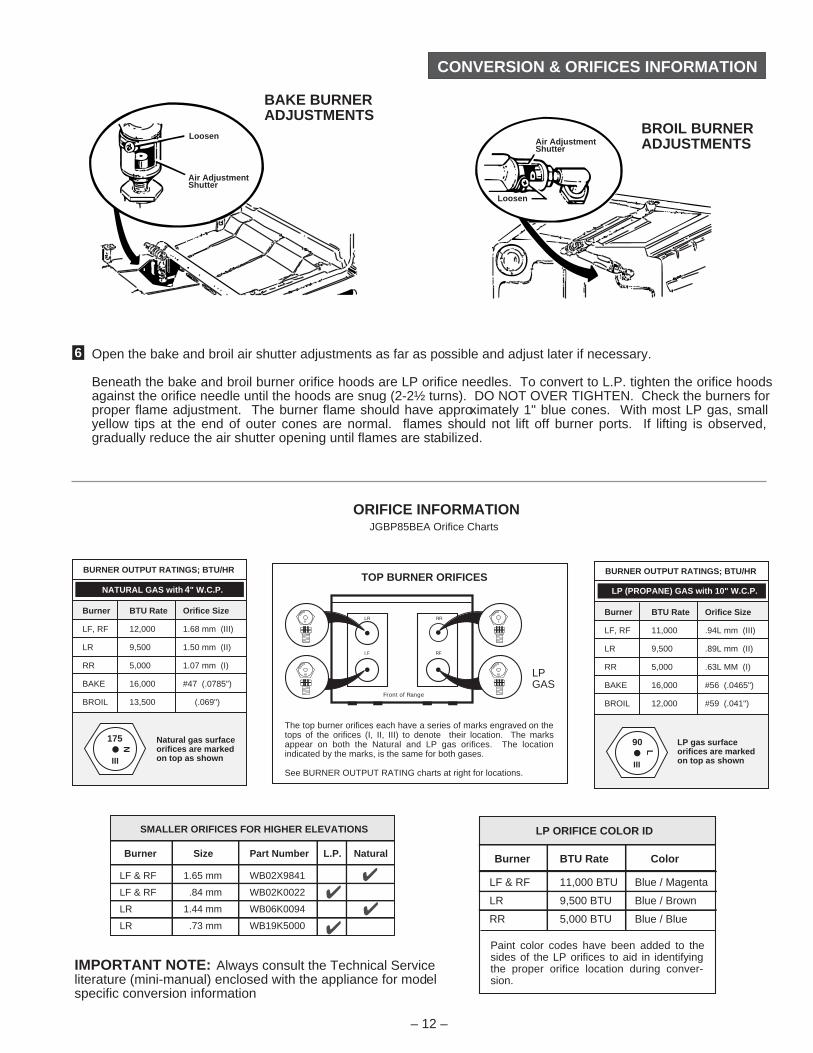
TOP BURNER FLAME ADJUSTMENTSThe top burners do not have air shutters adjustments and use non-adjustable orifices. If the flame lifts off of the burner, or if you experience "Yellow Tip" flames and/or soot in the flames, be sure to check the following:
Gas pressure: 4" W.C.P. (natural) and 10" W.C.P. (L.P.)Inspect orifice to be sure it is drilled in the center and free of debris or burrs.Be sure the correct size orifice is in the proper locationMake sure the range was properly converted if on L.P.If the cause of sooting can not be found in the above checks, replace the orifice with one having a smaller diameter opening
RR
LP GAS
LR
LF RF
Front of Range
TOP BURNER ORIFICES
The top burner orifices each have a series of marks engraved on the tops of the orifices (I, II, III) to denote their location. The marks appear on both the Natural and LP gas orifices. The location indicated by the marks, is the same for both gases.
See BURNER OUTPUT RATING charts at right for locations.
LF & RF 1.65 mm WB02X9841
LF & RF .84 mm WB02K0022
LR 1.44 mm WB06K0094
LR .73 mm WB19K5000
Burner Size Part Number L.P. Natural
SMALLER ORIFICES FOR HIGHER ELEVATIONS
LF & RF 11,000 BTU Blue / Magenta
LR 9,500 BTU Blue / Brown
RR 5,000 BTU Blue / Blue
Burner BTU Rate Color
LP ORIFICE COLOR ID
Paint color codes have been added to the sides of the LP orifices to aid in identifying the proper orifice location during conver-sion.
CONVERSION & ORIFICES INFORMATION
– 12 –
Burner BTU Rate Orifice Size
LF, RF 12,000 1.68 mm (III)
LR 9,500 1.50 mm (II)
RR 5,000 1.07 mm (I)
BAKE 16,000 #47 (.0785")
BROIL 13,500 (.069")
NATURAL GAS with 4" W.C.P.
BURNER OUTPUT RATINGS; BTU/HR
175
III
Natural gas surfaceorifices are markedon top as shown
N
Burner BTU Rate Orifice Size
LF, RF 11,000 .94L mm (III)
LR 9,500 .89L mm (II)
RR 5,000 .63L MM (I)
BAKE 16,000 #56 (.0465")
BROIL 12,000 #59 (.041")
LP (PROPANE) GAS with 10" W.C.P.
BURNER OUTPUT RATINGS; BTU/HR
III
90 LP gas surfaceorifices are markedon top as shown
L
Air AdjustmentShutter
Loosen
Air AdjustmentShutter
Loosen
6 Open the bake and broil air shutter adjustments as far as possible and adjust later if necessary.
Beneath the bake and broil burner orifice hoods are LP orifice needles. To convert to L.P. tighten the orifice hoods against the orifice needle until the hoods are snug (2-2½ turns). DO NOT OVER TIGHTEN. Check the burners for proper flame adjustment. The burner flame should have approximately 1" blue cones. With most LP gas, small yellow tips at the end of outer cones are normal. flames should not lift off burner ports. If lifting is observed, gradually reduce the air shutter opening until flames are stabilized.
ORIFICE INFORMATION
IMPORTANT NOTE: Always consult the Technical Serviceliterature (mini-manual) enclosed with the appliance for modelspecific conversion information
JGBP85BEA Orifice Charts
BAKE BURNERADJUSTMENTS
BROIL BURNERADJUSTMENTS
CONTROL PANEL ACCESS
– 13 –
HINGED ONBACK SIDE
FLIP PANEL UP TO ACCESSFLUORESCENT LIGHT
LOOSEN THIS SCREW TORAISE CONTROL PANEL
BE SURE TAB ISIN SLOT WHENREINSTALLING
REMOVE 2 SCREWS TO REMOVE CRYSTAL
A
BC
SIDEFRAME
VENT DEFLECTOR
Pull control panel down and forward to release it from the vent deflector
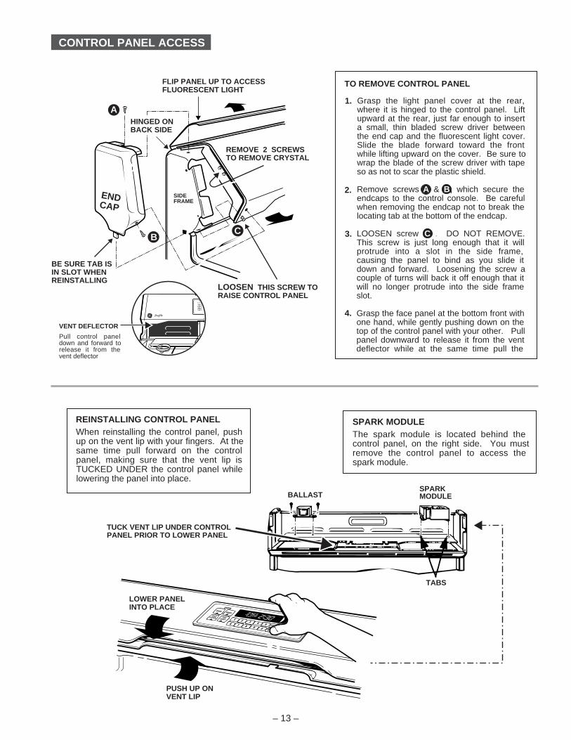
Grasp the light panel cover at the rear, where it is hinged to the control panel. Lift upward at the rear, just far enough to insert a small, thin bladed screw driver between the end cap and the fluorescent light cover. Slide the blade forward toward the front while lifting upward on the cover. Be sure to wrap the blade of the screw driver with tape so as not to scar the plastic shield.
Remove screws A & B, which secure the endcaps to the control console. Be careful when removing the endcap not to break the locating tab at the bottom of the endcap.
LOOSEN screw. C . DO NOT REMOVE. This screw is just long enough that it will protrude into a slot in the side frame, causing the panel to bind as you slide it down and forward. Loosening the screw a couple of turns will back it off enough that it will no longer protrude into the side frame slot.
Grasp the face panel at the bottom front with one hand, while gently pushing down on the top of the control panel with your other. Pull panel downward to release it from the vent deflector while at the same time pull the
TO REMOVE CONTROL PANEL
1.
2.
3.
4.
SPARK MODULEThe spark module is located behind the control panel, on the right side. You must remove the control panel to access the spark module.
REINSTALLING CONTROL PANELWhen reinstalling the control panel, push up on the vent lip with your fingers. At the same time pull forward on the control panel, making sure that the vent lip is TUCKED UNDER the control panel while lowering the panel into place.
PUSH UP ONVENT LIP
LOWER PANELINTO PLACE
SPARKMODULEBALLAST
TABS
TUCK VENT LIP UNDER CONTROLPANEL PRIOR TO LOWER PANEL
ENDCAP
SET
ON
SET
DELAYBROIL
BAKELOCKED
CLEANDOOR
STARTCOOK
CLOCKSTOP
CLEANTIMER
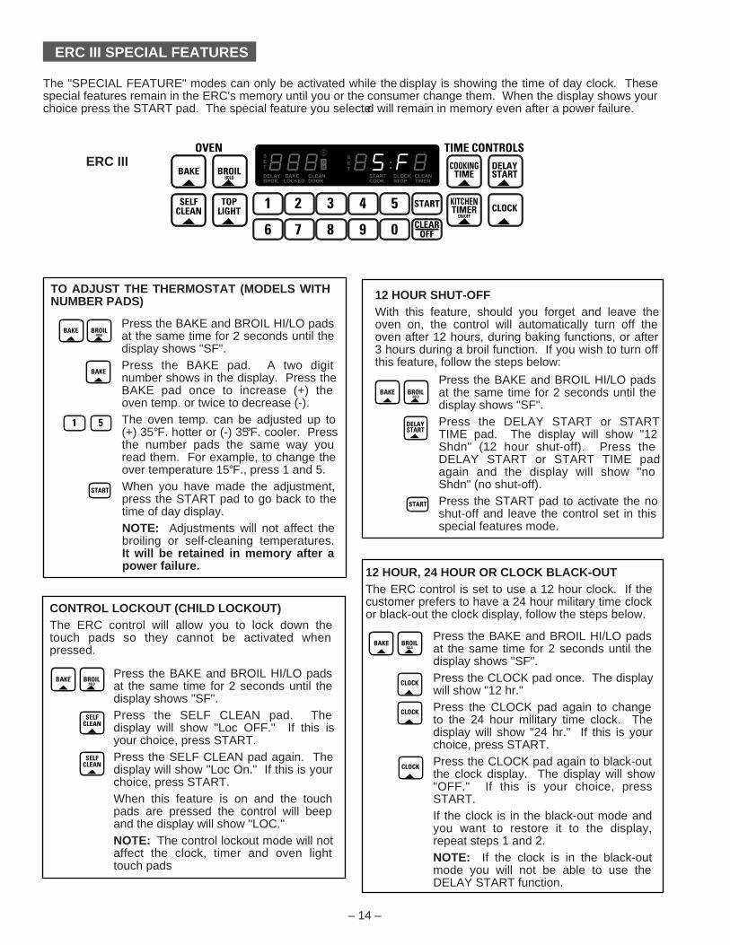
12 HOUR SHUT-OFFWith this feature, should you forget and leave the oven on, the control will automatically turn off the oven after 12 hours, during baking functions, or after 3 hours during a broil function. If you wish to turn off this feature, follow the steps below:
Press the BAKE and BROIL HI/LO pads at the same time for 2 seconds until the display shows "SF".Press the DELAY START or START TIME pad. The display will show "12 Shdn" (12 hour shut-off). Press the DELAY START or START TIME pad again and the display will show "no Shdn" (no shut-off).Press the START pad to activate the no shut-off and leave the control set in this special features mode.
ERC III SPECIAL FEATURES
CONTROL LOCKOUT (CHILD LOCKOUT)The ERC control will allow you to lock down the touch pads so they cannot be activated when pressed.
Press the BAKE and BROIL HI/LO pads at the same time for 2 seconds until the display shows "SF".Press the SELF CLEAN pad. The display will show "Loc OFF." If this is your choice, press START.Press the SELF CLEAN pad again. The display will show "Loc On." If this is your choice, press START.When this feature is on and the touch pads are pressed the control will beep and the display will show "LOC."NOTE: The control lockout mode will not affect the clock, timer and oven light touch pads
12 HOUR, 24 HOUR OR CLOCK BLACK-OUTThe ERC control is set to use a 12 hour clock. If the customer prefers to have a 24 hour military time clock or black-out the clock display, follow the steps below.
Press the BAKE and BROIL HI/LO pads at the same time for 2 seconds until the display shows "SF".Press the CLOCK pad once. The display will show "12 hr."Press the CLOCK pad again to change to the 24 hour military time clock. The display will show "24 hr." If this is your choice, press START.Press the CLOCK pad again to black-out the clock display. The display will show "OFF." If this is your choice, press START.If the clock is in the black-out mode and you want to restore it to the display, repeat steps 1 and 2.NOTE: If the clock is in the black-out mode you will not be able to use the DELAY START function.
TO ADJUST THE THERMOSTAT (MODELS WITH NUMBER PADS)
Press the BAKE and BROIL HI/LO pads at the same time for 2 seconds until the display shows "SF".Press the BAKE pad. A two digit number shows in the display. Press the BAKE pad once to increase (+) the oven temp. or twice to decrease (-).The oven temp. can be adjusted up to (+) 35°F. hotter or (-) 35°F. cooler. Press the number pads the same way you read them. For example, to change the over temperature 15°F., press 1 and 5.When you have made the adjustment, press the START pad to go back to the time of day display.NOTE: Adjustments will not affect the broiling or self-cleaning temperatures. It will be retained in memory after a power failure.
– 14 –
The "SPECIAL FEATURE" modes can only be activated while the display is showing the time of day clock. These special features remain in the ERC's memory until you or the consumer change them. When the display shows your choice press the START pad. The special feature you selected will remain in memory even after a power failure.
ERC III
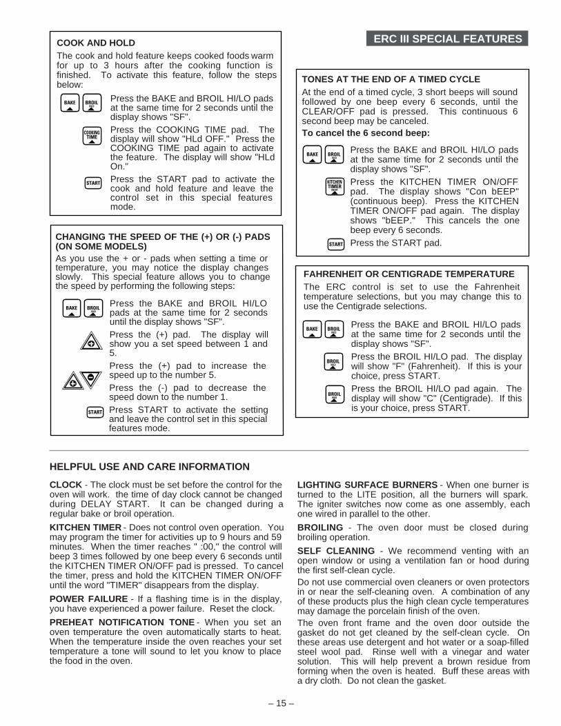
TONES AT THE END OF A TIMED CYCLEAt the end of a timed cycle, 3 short beeps will sound followed by one beep every 6 seconds, until the CLEAR/OFF pad is pressed. This continuous 6 second beep may be canceled.To cancel the 6 second beep:
Press the BAKE and BROIL HI/LO pads at the same time for 2 seconds until the display shows "SF".Press the KITCHEN TIMER ON/OFF pad. The display shows "Con bEEP" (continuous beep). Press the KITCHEN TIMER ON/OFF pad again. The display shows "bEEP." This cancels the one beep every 6 seconds.Press the START pad.
COOK AND HOLDThe cook and hold feature keeps cooked foods warm for up to 3 hours after the cooking function is finished. To activate this feature, follow the steps below:
Press the BAKE and BROIL HI/LO pads at the same time for 2 seconds until the display shows "SF".Press the COOKING TIME pad. The display will show "HLd OFF." Press the COOKING TIME pad again to activate the feature. The display will show "HLd On." Press the START pad to activate the cook and hold feature and leave the control set in this special features mode.
ERC III SPECIAL FEATURES
FAHRENHEIT OR CENTIGRADE TEMPERATUREThe ERC control is set to use the Fahrenheit temperature selections, but you may change this to use the Centigrade selections.
Press the BAKE and BROIL HI/LO pads at the same time for 2 seconds until the display shows "SF".Press the BROIL HI/LO pad. The display will show "F" (Fahrenheit). If this is your choice, press START.Press the BROIL HI/LO pad again. The display will show "C" (Centigrade). If this is your choice, press START.
CHANGING THE SPEED OF THE (+) OR (-) PADS (ON SOME MODELS)As you use the + or - pads when setting a time or temperature, you may notice the display changes slowly. This special feature allows you to change the speed by performing the following steps:
Press the BAKE and BROIL HI/LO pads at the same time for 2 seconds until the display shows "SF".Press the (+) pad. The display will show you a set speed between 1 and 5.Press the (+) pad to increase the speed up to the number 5.Press the (-) pad to decrease the speed down to the number 1.Press START to activate the setting and leave the control set in this special features mode.
– 15 –
HELPFUL USE AND CARE INFORMATION
CLOCK - The clock must be set before the control for the oven will work. the time of day clock cannot be changed during DELAY START. It can be changed during a regular bake or broil operation.
KITCHEN TIMER - Does not control oven operation. You may program the timer for activities up to 9 hours and 59 minutes. When the timer reaches " :00," the control will beep 3 times followed by one beep every 6 seconds until the KITCHEN TIMER ON/OFF pad is pressed. To cancel the timer, press and hold the KITCHEN TIMER ON/OFF until the word "TIMER" disappears from the display.
POWER FAILURE - If a flashing time is in the display, you have experienced a power failure. Reset the clock.
PREHEAT NOTIFICATION TONE - When you set an oven temperature the oven automatically starts to heat. When the temperature inside the oven reaches your set temperature a tone will sound to let you know to place the food in the oven.
LIGHTING SURFACE BURNERS - When one burner is turned to the LITE position, all the burners will spark. The igniter switches now come as one assembly, each one wired in parallel to the other.
BROILING - The oven door must be closed during broiling operation.
SELF CLEANING - We recommend venting with an open window or using a ventilation fan or hood during the first self-clean cycle.Do not use commercial oven cleaners or oven protectors in or near the self-cleaning oven. A combination of any of these products plus the high clean cycle temperatures may damage the porcelain finish of the oven.The oven front frame and the oven door outside the gasket do not get cleaned by the self-clean cycle. On these areas use detergent and hot water or a soap-filled steel wool pad. Rinse well with a vinegar and water solution. This will help prevent a brown residue from forming when the oven is heated. Buff these areas with a dry cloth. Do not clean the gasket.
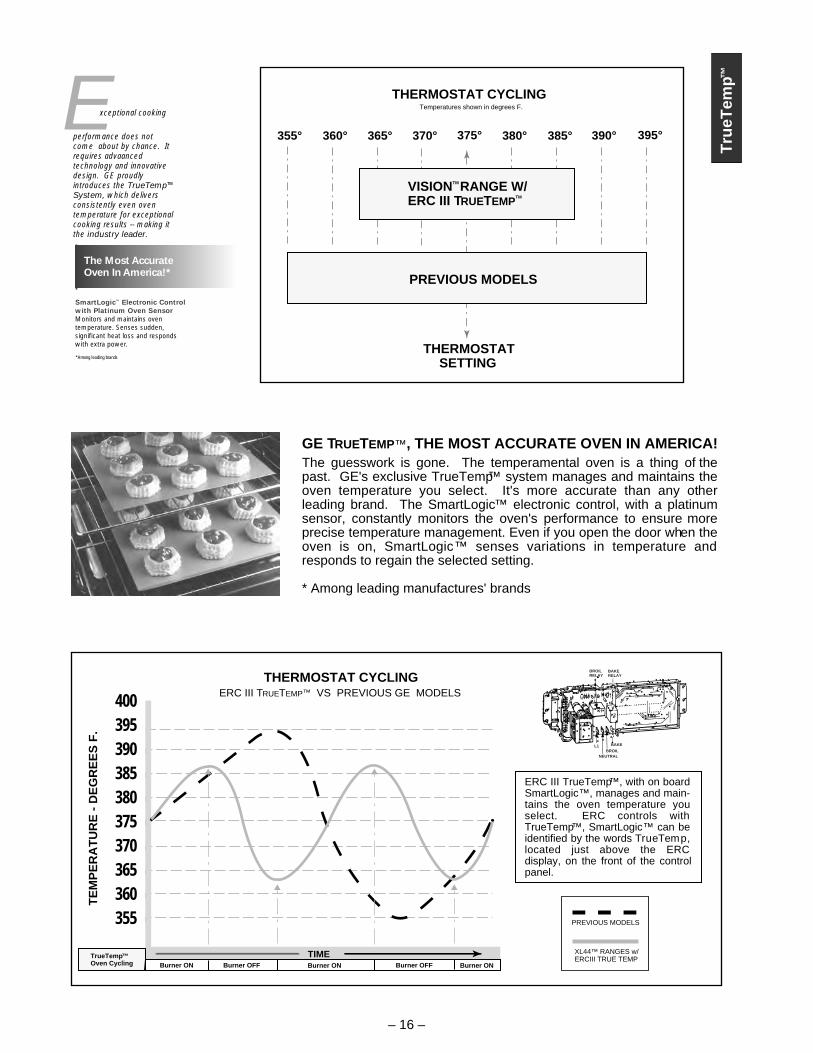
VISIONTM RANGE W/ERC III TRUETEMP
TM
375° 380° 395° 365° 370° 390° 360° 385° 355°
PREVIOUS MODELS
THERMOSTATSETTING
THERMOSTAT CYCLINGTemperatures shown in degrees F.
GE TRUETEMP™, THE MOST ACCURATE OVEN IN AMERICA!The guesswork is gone. The temperamental oven is a thing of the past. GE's exclusive TrueTemp™ system manages and maintains the oven temperature you select. It's more accurate than any other leading brand. The SmartLogic™ electronic control, with a platinum sensor, constantly monitors the oven's performance to ensure more precise temperature management. Even if you open the door when the oven is on, SmartLogic™ senses variations in temperature and responds to regain the selected setting.
* Among leading manufactures' brands
Tru
eTem
p™
– 16 –
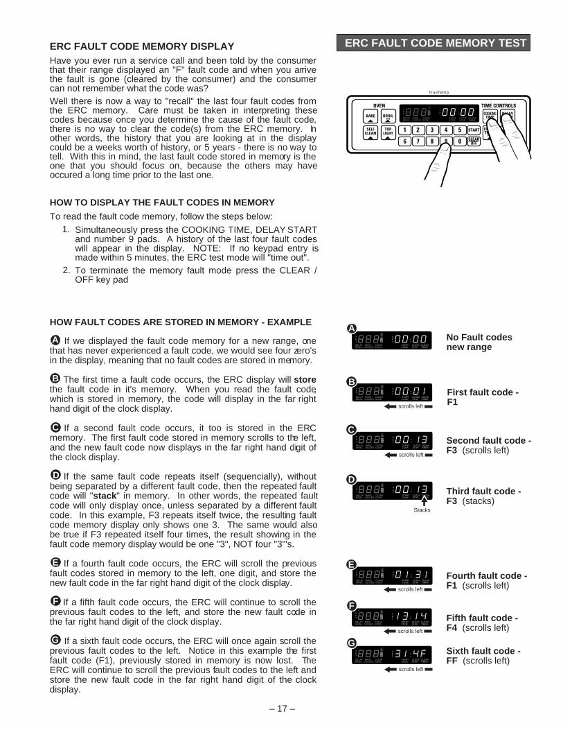
400 395 390 385 380 375 370 365 360 355
TE
MP
ER
AT
UR
E -
DE
GR
EE
S F
.
XL44™ RANGES w/ERCIII TRUE TEMP
PREVIOUS MODELS
THERMOSTAT CYCLINGERC III TRUETEMP™ VS PREVIOUS GE MODELS
TIMEBurner ON Burner ONBurner OFF Burner OFF Burner ON
TrueTemp™Oven Cycling
ERC III TrueTemp™, with on board SmartLogic™, manages and main-tains the oven temperature you select. ERC controls with TrueTemp™, SmartLogic™ can be identified by the words TrueTemp, located just above the ERC display, on the front of the control panel.
SmartLogic™ Electronic Controlwith Platinum Oven SensorMonitors and maintains oven temperature. Senses sudden, significant heat loss and respondswith extra power.
The Most AccurateOven In America!*
*Among leading brands
xceptional cooking
performance does not come about by chance. It requires advaanced technology and innovative design. GE proudly introduces the TrueTemp™ System, which delivers consistently even oven temperature for exceptional cooking results -- making it the industry leader.
E
BROILRELAY
BAKERELAY
BAKE
BROILNEUTRAL
L1
ERC FAULT CODE MEMORY TEST
– 17 –
TrueTemp
SET
ON
SET
DELAYBROIL
BAKELOCKED
CLEANDOOR
STARTCOOK
CLOCKSTOP
CLEANTIMER
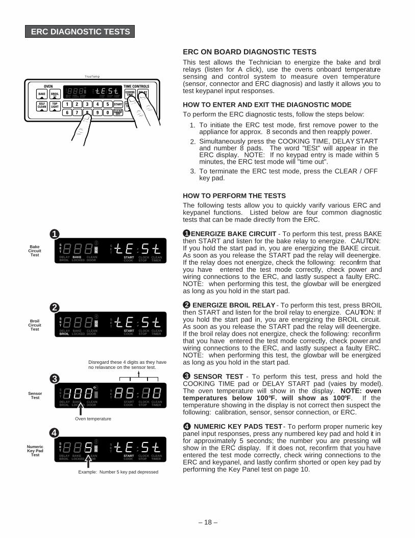
ERC FAULT CODE MEMORY DISPLAYHave you ever run a service call and been told by the consumer that their range displayed an "F" fault code and when you arrive the fault is gone (cleared by the consumer) and the consumer can not remember what the code was?Well there is now a way to "recall" the last four fault codes from the ERC memory. Care must be taken in interpreting these codes because once you determine the cause of the fault code, there is no way to clear the code(s) from the ERC memory. In other words, the history that you are looking at in the display could be a weeks worth of history, or 5 years - there is no way to tell. With this in mind, the last fault code stored in memory is the one that you should focus on, because the others may have occured a long time prior to the last one.
HOW TO DISPLAY THE FAULT CODES IN MEMORY
To read the fault code memory, follow the steps below:
If we displayed the fault code memory for a new range, one that has never experienced a fault code, we would see four zero's in the display, meaning that no fault codes are stored in memory.
The first time a fault code occurs, the ERC display will store the fault code in it's memory. When you read the fault code, which is stored in memory, the code will display in the far right hand digit of the clock display.
If a second fault code occurs, it too is stored in the ERC memory. The first fault code stored in memory scrolls to the left, and the new fault code now displays in the far right hand digit of the clock display.
If the same fault code repeats itself (sequencially), without being separated by a different fault code, then the repeated fault code will "stack" in memory. In other words, the repeated fault code will only display once, unless separated by a different fault code. In this example, F3 repeats itself twice, the resulting fault code memory display only shows one 3. The same would also be true if F3 repeated itself four times, the result showing in the fault code memory display would be one "3", NOT four "3"'s.
If a fourth fault code occurs, the ERC will scroll the previous fault codes stored in memory to the left, one digit, and store the new fault code in the far right hand digit of the clock display.
If a fifth fault code occurs, the ERC will continue to scroll the previous fault codes to the left, and store the new fault code in the far right hand digit of the clock display.
If a sixth fault code occurs, the ERC will once again scroll the previous fault codes to the left. Notice in this example the first fault code (F1), previously stored in memory is now lost. The ERC will continue to scroll the previous fault codes to the left and store the new fault code in the far right hand digit of the clock display.
Simultaneously press the COOKING TIME, DELAY START and number 9 pads. A history of the last four fault codes will appear in the display. NOTE: If no keypad entry is made within 5 minutes, the ERC test mode will "time out".To terminate the memory fault mode press the CLEAR / OFF key pad
1.
2.
SET
ON
SET
DELAYBROIL
BAKELOCKED
CLEANDOOR
STARTCOOK
CLOCKSTOP
CLEANTIMER
SET
ON
SET
DELAYBROIL
BAKELOCKED
CLEANDOOR
STARTCOOK
CLOCKSTOP
CLEANTIMER
SET
ON
SET
DELAYBROIL
BAKELOCKED
CLEANDOOR
STARTCOOK
CLOCKSTOP
CLEANTIMER
A
SET
ON
SET
DELAYBROIL
BAKELOCKED
CLEANDOOR
STARTCOOK
CLOCKSTOP
CLEANTIMER
G
SET
ON
SET
DELAYBROIL
BAKELOCKED
CLEANDOOR
STARTCOOK
CLOCKSTOP
CLEANTIMER
F
B
No Fault codesnew range
First fault code -F1
C
SET
ON
SET
DELAYBROIL
BAKELOCKED
CLEANDOOR
STARTCOOK
CLOCKSTOP
CLEANTIMER
D
SET
ON
SET
DELAYBROIL
BAKELOCKED
CLEANDOOR
STARTCOOK
CLOCKSTOP
CLEANTIMER
E
Second fault code -F3 (scrolls left)
Third fault code - F3 (stacks)
Fourth fault code - F1 (scrolls left)
Fifth fault code - F4 (scrolls left)
Sixth fault code - FF (scrolls left)
A
B
C
D
G
F
E
scrolls left
scrolls left
scrolls left
scrolls left
scrolls left
Stacks
HOW FAULT CODES ARE STORED IN MEMORY - EXAMPLE
ERC DIAGNOSTIC TESTS
– 18 –
ERC ON BOARD DIAGNOSTIC TESTSThis test allows the Technician to energize the bake and broil relays (listen for A click), use the ovens onboard temperature sensing and control system to measure oven temperature (sensor, connector and ERC diagnosis) and lastly it allows you to test keypanel input responses.
HOW TO ENTER AND EXIT THE DIAGNOSTIC MODETo perform the ERC diagnostic tests, follow the steps below:
HOW TO PERFORM THE TESTSThe following tests allow you to quickly varify various ERC and keypanel functions. Listed below are four common diagnostic tests that can be made directly from the ERC.
ENERGIZE BAKE CIRCUIT - To perform this test, press BAKE then START and listen for the bake relay to energize. CAUTION: If you hold the start pad in, you are energizing the BAKE circuit. As soon as you release the START pad the relay will deenergize. If the relay does not energize, check the following: reconfirm that you have entered the test mode correctly, check power and wiring connections to the ERC, and lastly suspect a faulty ERC. NOTE: when performing this test, the glowbar will be energized as long as you hold in the start pad.
ENERGIZE BROIL RELAY - To perform this test, press BROIL then START and listen for the broil relay to energize. CAUTION: If you hold the start pad in, you are energizing the BROIL circuit. As soon as you release the START pad the relay will deenergize. If the broil relay does not energize, check the following: reconfirm that you have entered the test mode correctly, check power and wiring connections to the ERC, and lastly suspect a faulty ERC. NOTE: when performing this test, the glowbar will be energized as long as you hold in the start pad.
SENSOR TEST - To perform this test, press and hold the COOKING TIME pad or DELAY START pad (vaies by model). The oven temperature will show in the display. NOTE: oven temperatures below 100°F. will show as 100°F. If the temperature showing in the display is not correct then suspect the following: calibration, sensor, sensor connection, or ERC.
NUMERIC KEY PADS TEST - To perform proper numeric key panel input responses, press any numbered key pad and hold it in for approximately 5 seconds; the number you are pressing will show in the ERC display. If it does not, reconfirm that you have entered the test mode correctly, check wiring connections to the ERC and keypanel, and lastly confirm shorted or open key pad by performing the Key Panel test on page 10.
1
2
3
4
To initiate the ERC test mode, first remove power to the appliance for approx. 8 seconds and then reapply power.Simultaneously press the COOKING TIME, DELAY START and number 8 pads. The word "tESt" will appear in the ERC display. NOTE: If no keypad entry is made within 5 minutes, the ERC test mode will "time out".To terminate the ERC test mode, press the CLEAR / OFF key pad.
1.
2.
3.
TrueTemp
SET
ON
SET
DELAYBROIL
BAKELOCKED
CLEANDOOR
STARTCOOK
CLOCKSTOP
CLEANTIMER
SET
ON
SET
DELAYBROIL
BAKELOCKED
CLEANDOOR
STARTCOOK
CLOCKSTOP
CLEANTIMER
2
SET
ON
SET
DELAYBROIL
BAKELOCKED
CLEANDOOR
STARTCOOK
CLOCKSTOP
CLEANTIMER
1
SET
ON
SET
DELAYBROIL
BAKELOCKED
CLEANDOOR
STARTCOOK
CLOCKSTOP
CLEANTIMER
4
BakeCircuit
Test
BroilCircuit
Test
SensorTest
NumericKey Pad
Test
SET
ON
SET
DELAYBROIL
BAKELOCKED
CLEANDOOR
STARTCOOK
CLOCKSTOP
CLEANTIMER
3o
Example: Number 5 key pad depressed
Oven temperature
Disregard these 4 digits as they haveno relavance on the sensor test.
LOCK MOTOR
LOCK MOTORCOVER
COM
NC
COM
NO
Y YOF1
W
F2
W
5 1 S
REARLatch Switch
FRONTLatch Switch
Oven Temp.Sensor1100W at 75o F.2634W at 865o F.Latch circuit shown in
UNLOCKED mode
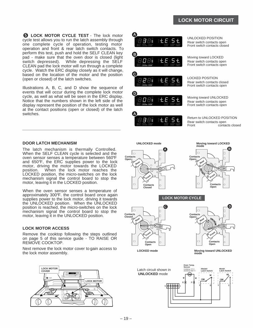
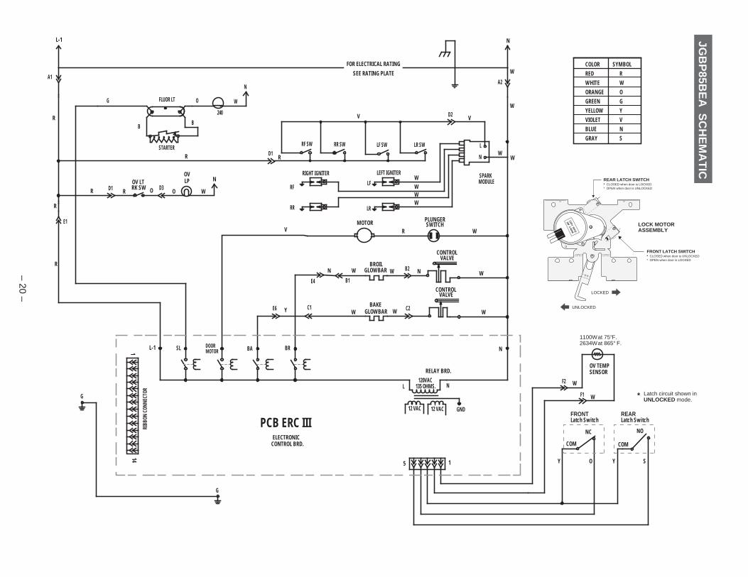
LOCK MOTOR CIRCUIT
DOOR LATCH MECHANISM
The latch mechanism is thermally Controlled. When the SELF CLEAN cycle is selected and the oven sensor senses a temperature between 560°F and 650°F, the ERC supplies power to the lock motor, driving the motor towards the LOCKED position. When the lock motor reaches the LOCKED position, the micro-switches on the lock mechanism signal the control board to stop the motor, leaving it in the LOCKED position.
When the oven sensor senses a temperature of approximately 300°F. the control board once again supplies power to the lock motor, driving it towards the UNLOCKED position. When the UNLOCKED position is reached, the micro-switches on the lock mechanism signal the control board to stop the motor, leaving it in the UNLOCKED position.
LOCK MOTOR ACCESSRemove the cooktop following the steps outlined on page 5 of this service guide - TO RAISE OR REMOVE COOKTOP.Next remove the lock motor cover to gain access to the lock motor assembly.
– 19 –
Rear
Front
Rear
Front
Rear
Front
Rear
Front
UNLOCKED mode Moving toward LOCKEDmode
LOCKED mode Moving toward UNLOCKEDmode
LOCK MOTOR CYCLE
A B
C D
ContactsClosed
ContactsOpen
ContactsOpen
ContactsOpen
LOCK MOTOR CYCLE TEST - The lock motor cycle test allows you to run the latch assembly through one complete cycle of operation, testing motor operation and front & rear latch switch contacts. To perform this test, push and hold the SELF CLEAN key pad - make sure that the oven door is closed (light switch depressed). While depressing the SELF CLEAN pad the lock motor will run through a complete cycle. Watch the ERC display closely as it will change, based on the location of the motor and the position (open or closed) of the latch switches.
Illustrations A, B, C, and D show the sequence of events that will occur during the complete lock motor cycle, as well as what will be seen in the ERC display. Notice that the numbers shown in the left side of the display represent the position of the lock motor as well at the contact positions (open or closed) of the latch switches.
5
SET
ON
SET
DELAYBROIL
BAKELOCKED
CLEANDOOR
STARTCOOK
CLOCKSTOP
CLEANTIMER
D
SET
ON
SET
DELAYBROIL
BAKELOCKED
CLEANDOOR
STARTCOOK
CLOCKSTOP
CLEANTIMER
A
SET
ON
SET
DELAYBROIL
BAKELOCKED
CLEANDOOR
STARTCOOK
CLOCKSTOP
CLEANTIMER
A
SET
ON
SET
DELAYBROIL
BAKELOCKED
CLEANDOOR
STARTCOOK
CLOCKSTOP
CLEANTIMER
B
SET
ON
SET
DELAYBROIL
BAKELOCKED
CLEANDOOR
STARTCOOK
CLOCKSTOP
CLEANTIMER
C
UNLOCKED POSITIONRear switch contacts openFront switch contacts closed
Moving toward LOCKEDRear switch contacts openFront switch contacts open
LOCKED POSITIONRear switch contacts closedFront switch contacts open
Moving toward UNLOCKEDRear switch contacts openFront switch contacts open
Return to UNLOCKED POSITIONRear switch contacts openFront contacts closed
ContactsOpen
ContactsOpen
ContactsOpen
ContactsClosed
BB
WC2
N
A2
E4
N
B1
BR
BROILGLOWBAR B2 N
D1
A1
L-1
R
BA
RK SWOV LT
OVLP
STARTER
G
G
SL
G
OR
C1
141
PCB ERC III
E1
D1 D3
E6
RIGHT IGNITER
RR
RF
RF SW RR SW
FLUOR LT
240
W
N
5 1
135 OHMS.
12 VAC
L120VAC
12 VAC
N
RELAY BRD.
ELECTRONICCONTROL BRD. COM
NO
FRONTLatch Switch
COM
NC
F1
F2
OV TEMPSENSOR
BAKEGLOWBAR
CONTROLVALVE
CONTROLVALVE
LEFT IGNITER
LR
LF
LF SW LR SW
MODULESPARK
N
L
WY
R
R
R
R
W
W
N
R
R
W
GND
Y YO
W
W
W
W
W W
W
W
WW
W
WW
FOR ELECTRICAL RATING
SEE RATING PLATE
O
O
S
DOORMOTOR
V
PLUNGERSWITCHMOTOR
V D2 V
JGB
P85B
EA
SC
HE
MA
TIC
RIBB
ON C
ONNE
CTOR
L-1 N
REARLatch Switch
COLOR SYMBOLRED RWHITE WORANGE OGREEN GYELLOW YVIOLET VBLUE NGRAY S
1100W at 75°F.2634W at 865° F.
– 20 –
120V 60HZ
3W 2 R
PM
LOCK MOTORASSEMBLY
REAR LATCH SWITCH* CLOSED when door is LOCKED* OPEN when door is UNLOCKED
FRONT LATCH SWITCH* CLOSED when door is UNLOCKED* OPEN when door is LOCKED
UNLOCKED
LOCKED
Latch circuit shown inUNLOCKED mode.
*
RK SWOV LT
OVLP
ORD1 D3R WO
A1
L-1
R
A2
N
W
BB
STARTER
G FLUOR LT
240
WOSL
ERC BOARD
A1
L-1
R
A2
N
WE1 R
R W
PLUNGERSWITCHMOTORDOOR
MOTOR
ERC BOARD
A2
N
W
A1
L-1
R E1 R V
A1
L-1
R
A2
N
WD1
RIGHT IGNITER
RR
RF
RF SW RR SW
LEFT IGNITER
LR
LF
LF SW LR SW
MODULESPARK
N
L
R R
W
WW
W
W
V D2 V
A2
N
W
E4
N
B1
BRBROIL
GLOWBAR B2 N
CONTROLVALVE
W W W
ERC BOARD
A1
L-1
R E1 R
A2
N
W
E6
Y
C1
BABAKE
GLOWBAR C2 N
CONTROLVALVE
W W W
ERC BOARD
A1
L-1
R E1 R
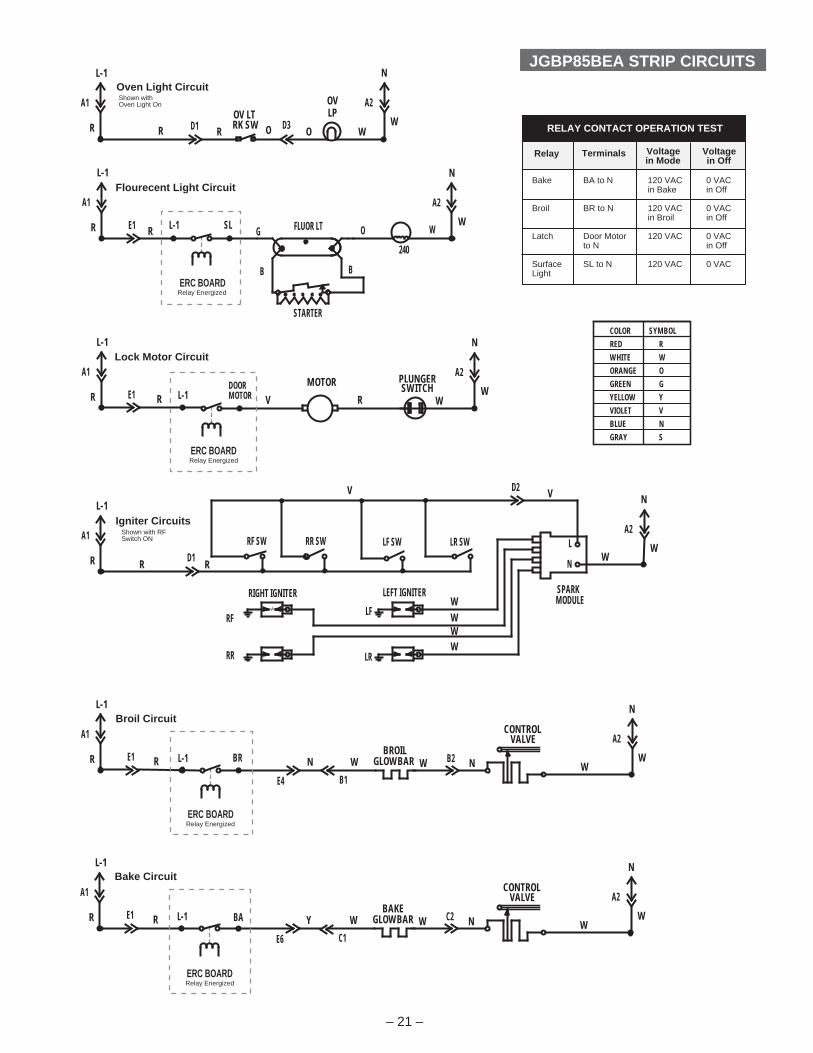
JGBP85BEA STRIP CIRCUITS
Relay Energized
Relay Energized
Relay Energized
Relay Energized
L-1
L-1
L-1
L-1
Oven Light Circuit
Flourecent Light Circuit
Lock Motor Circuit
Igniter Circuits
Broil Circuit
Bake Circuit
Bake BA to N 120 VAC 0 VAC in Bake in Off
Broil BR to N 120 VAC 0 VAC in Broil in Off
Latch Door Motor 120 VAC 0 VAC to N in Off
Surface SL to N 120 VAC 0 VACLight
Relay Terminals Voltagein Mode
RELAY CONTACT OPERATION TEST
Voltagein Off
COLOR SYMBOLRED RWHITE WORANGE OGREEN GYELLOW YVIOLET VBLUE NGRAY S
Shown withOven Light On
Shown with RFSwitch ON
– 21 –

JGBP85BEA DIAGNOSTIC INFO
– 22 –
FUNCTION TEST POINTS
Bake 11 to 13Broil 10 to 13Self Clean 8 to 13Top Light 8 to 121 9 to 142 8 to 143 5 to 136 6 to 127 7 to 148 7 to 12Cooking Time 10 to 12Delay Start 11 to 12Kitchen Timer 9 to 13Clock 9 to 124 5 to 125 6 to 13Start 1 to 2Clear 3 to 49 7 to 1310 10 to 14
KEY PANEL TESTS
KITCHEN End Of Cycle beep bEEP <–> Con bEEPTIMER selection of continuous or non-continuous tones
BROIL Degree switching from °F <–> °C Centigrade to Fahrenheit
CLOCK Time display mode 12 hr –> 24 hr –> OFF –> 12 hr 12 / 24 / Blank
COOKING Cook & Hold feature to HLd On <–> HLd OFFTIME maintain food at 170°F when timed cooking function ends. Enable / disable function
SELF CLEAN Child Lockout disables Loc On <–> Loc OFF heating mode keys and displays "LOC" when key depressed
DELAY START 12 hr Shut Down Override 12 Shdn <–> no Shdn enables / disables 12 hour safety shutdown feature
BAKE User Temperature Offset for oven temperature calibration
CLOCK and Sales Mode Display will scroll the following:KITCHEN Display offTIMER BAKE icon on Temp digits 350 On icon and BAKE icon on Pause 2 seconds Display off BROIL icon on Temp digits on LO ON icon & broil element icon on Pause 2 seconds Temp digit on HI and broil element icon Pause 2 seconds
ERC III SPECIAL FUNCTIONS (SF) MODEEnter Special Functions mode by holding BAKE and BROIL pads
for 2 seconds, until "SF" shows in display1
14
NOTE: Resistance values may vary from 20 to 90 ohms. An "OPEN" circuit would indicate a defect in the touch pad.
KEY PANELRIBBON
Failure Meaning Suspect / CheckCode
FFF Control error, failed ERC EEPROM
F0 Shorted CLEAR/OFF key Membrane switch ERC F7 Any shorted membrane Membrane switch key other than CLEAR/ ERC OFF
F2 Control senses oven High resistance connection inDuring temp. above 615 deg. sensor circuitBAKE F. ERC (welded bake relay con- tacts) F2 Control senses oven High resistance connection inDuring temp. above 915 deg. sensor circuitCLEAN F. ERC (welded clean relay con- tacts) Both Lock switch 1 & 2 closed at the same time F3 Open sensor; sensor re- Sensor / sensor circuit con- sistance exceeds 2900 nections ohms during bake broil or clean
F4 Shorted sensor; sensor Sensor / sensor circuit con- resistance is less than nections 2900 ohms during bake broil or clean
FF Door motor safety circuit ERC
FAILURE CODES - "F" CODES
ERC III WITH TRUE TEMP™ AND SMARTLOGIC™
TrueTemp
Bake BA to N 120 VAC 0 VAC in Bake in Off
Broil BR to N 120 VAC 0 VAC in Broil in Off
Door Door Motor 120 VAC 0 VACMotor to N in Off
Surface SL to N 120 VAC 0 VACLight
Relay /Mode
Terminals Voltagein Mode
ERC RELAY CONTACT OPERATION TEST
Voltagein Off
KEY PAD CONTROLS: ERC DISPLAY WILL SHOW:
IMPORTANT NOTE: While the information listed on this page is specific to one model, it reflects the type of information available on most mini-manuals enclosed with each product. Always consult the mini-manual for model specific information.

D1
COMNC
SWLCH
NO
1
BABR
F2
F1
5
D6
GND
N
4 OHMS.32VAC
4 OHMS.21VAC
120VAC135 OHMS.
B1
ELECTRONICCONTROL BRD.
GLOWBARBAKE
D5
A1
L-1
D4
C1
E1
RR
GLOWBARBROIL
LR
RR SWRF SW
RF
RIGHT IGNITER
LF SW
LF
LEFT IGNITER
D3LATCH SWITCH/DOOR SWITCH
NO = LOCKEDNC = UNLOCKED
A2
VALVECONTROL
E2
VALVECONTROL
D1
SPARKMODULE
LR SW
C2
N
L
N
SEE RATING PLATEFOR ELECTRICAL RATING
WW
S
YO
Y W W
R
R
O
R
N
RK SWOV LT
O
OV
O W
N
R
W W
R
W
N
W
WW
W
N
W
W
W
W
W
W
JGB
P30B
EA
SC
HE
MA
TIC
L-1
COLOR SYMBOLRED RWHITE WORANGE OGREEN GYELLOW YVIOLET VBLUE NGRAY S
– 23 –
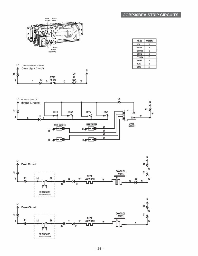
OVEN TEMP SENSOR1100W at 75°F.2634W at 865°F.
Terminals Voltage (AC)
L1 to N 120 VAC at all times
BA to N 120 VAC in BAKE mode
BR to N 120 VAC in BROIL mode
ERT CONTROL VOLTAGES
RK SWOV LT
OVLP
OOD6O W
A1
L-1
R
NOven Light Circuit
A1
L-1
R
A2
N
WC1
RIGHT IGNITER
RR
RF
RF SW RR SW
LEFT IGNITER
LR
LF
LF SW LR SW
MODULESPARK
N
L
R R
W
WW
W
W
C2Igniter Circuits
A2
N
W
D4
N
E1
BRBROIL
GLOWBAR
CONTROLVALVE
W W W
ERC BOARD
A1
L-1
R D1
Relay Energized
L-1
Broil Circuit
E2 N
D1W
A2
N
W
D6
Y
B1
BABROIL
GLOWBAR
CONTROLVALVE
W W
ERC BOARD
A1
L-1
R D1
Relay Energized
L-1
Bake Circuit
N
D1W
JGBP30BEA STRIP CIRCUITS
COLOR SYMBOLRED RWHITE WORANGE OGREEN GYELLOW YVIOLET VBLUE NGRAY S
– 24 –
RF Switch Shown ON
Oven Light show in ON position
BROILRELAY
BAKERELAY
BAKE
BROILNEUTRAL
L1
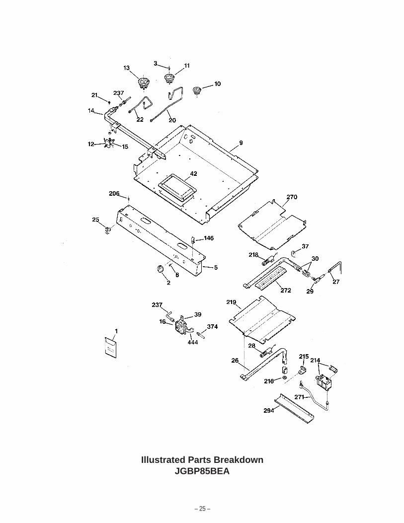
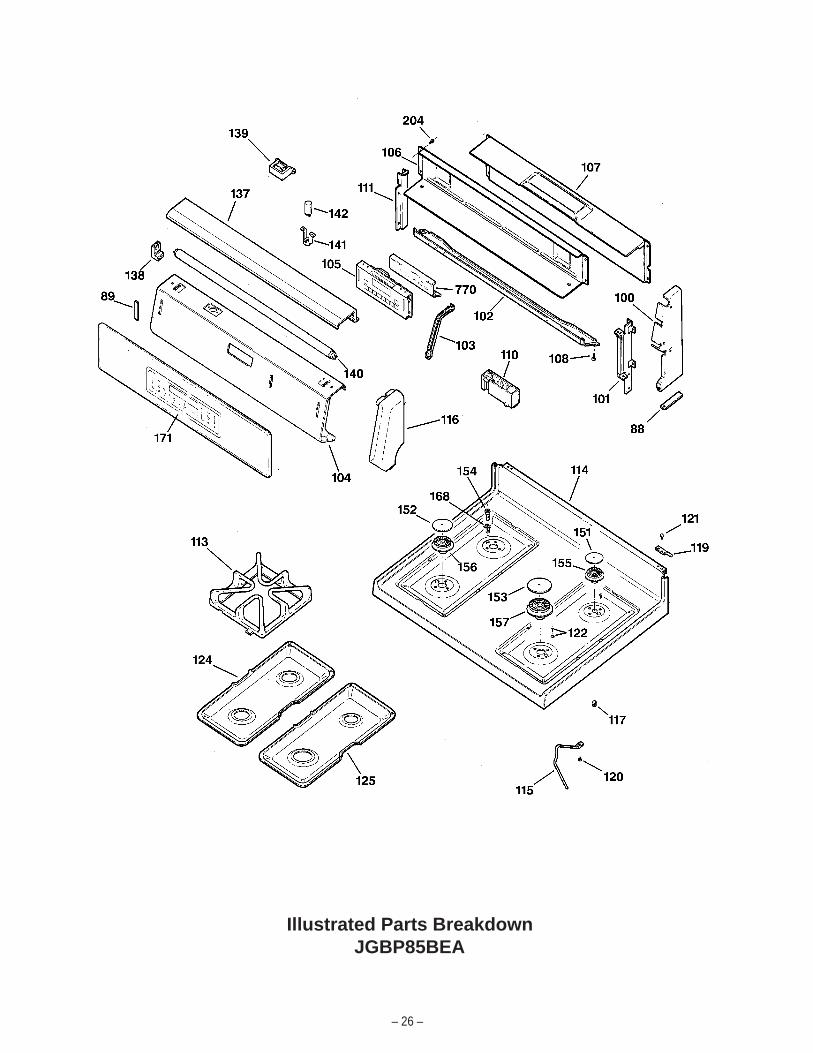
Illustrated Parts BreakdownJGBP85BEA
– 25 –
Illustrated Parts BreakdownJGBP85BEA
– 26 –
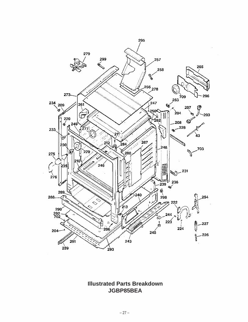
Illustrated Parts BreakdownJGBP85BEA
– 27 –
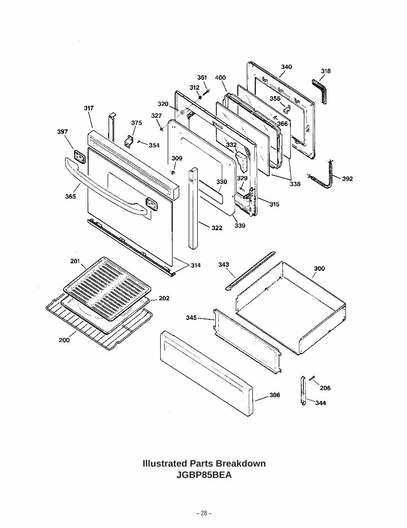
Illustrated Parts BreakdownJGBP85BEA
– 28 –

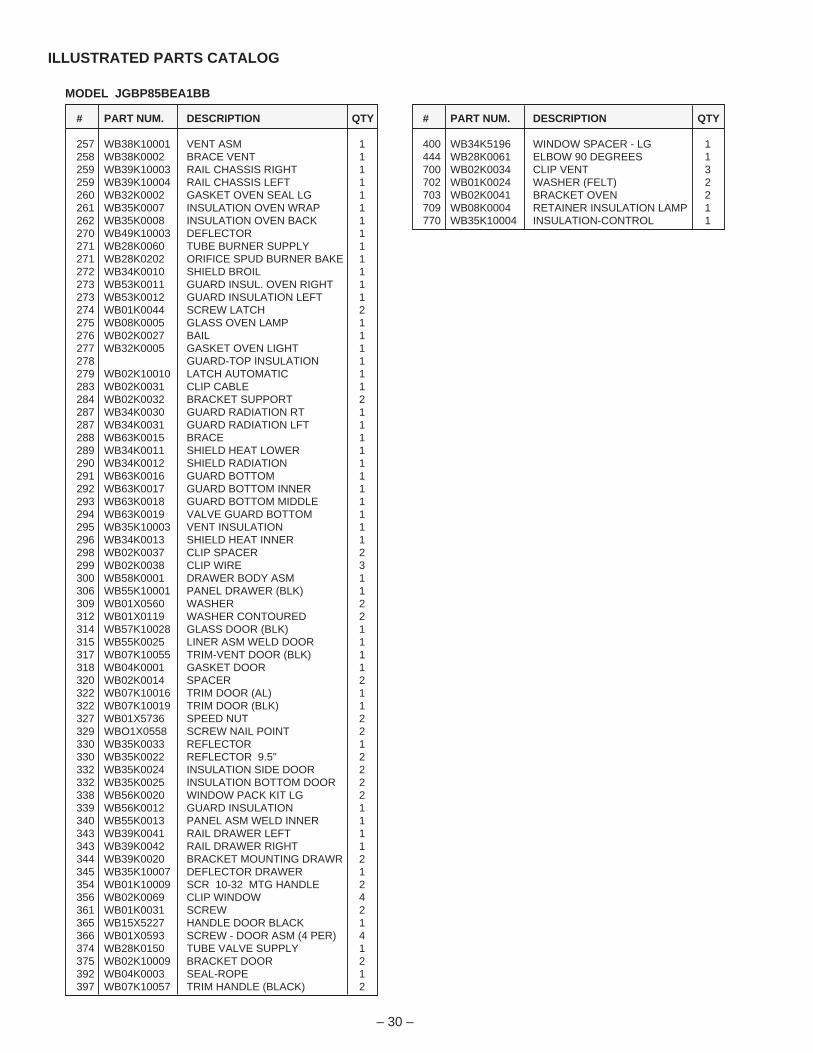
# PART NUM. DESCRIPTION QTY
1 49-8856 MANUAL-USE & CARE 11 31-20639 MANUAL-MINI/ELEC. DIAG. 11 WB02K0020 BRACKET ASM ANTI-TIP 12 WB03K10043 KNOB-TOP BURNERS (BLK) 13 WB28K10031 ORIFICE-LP RIGHT REAR 13 WB28K10022 ORIFICE-NG LEFT REAR 13 WB28K10023 ORIFICE-LP LEFT REAR 13 WB28K10030 ORIFICE-NG FRONT RT & LT 23 WB28K10032 ORIFICE-LP FRONT RT & LT 23 WB28K10029 ORIFICE-NG RIGHT REAR 15 WB36X10071 PANEL-MANIFOLD (BLK) 18 WB01K10002 SCREW 8-32 49 WB63K0023 BOX BURNER 110 WB02K10007 BRACKET-BURNER SMALL 111 WB02K10006 BRACKET-BURNER 212 WB24K10003 SWITCH-BURNER VALVE 413 WB02K10008 BRACKET-BURNER LARGE 114 WB28K10028 MANIFOLD PIPE 115 WB21K0040 VALVE BURNER RT FRONT 115 WB21K0041 VALVE BURNER LEFT 215 WB21K0042 VALVE BURNER RT RR 116 WB19K10001 REGULATOR PRESSURE 120 WB28K10026 TUBE-BURNER RIGHT REAR 120 WB28K10027 TUBE-BURNER LEFT REAR 121 WB01K0083 SCREW MTG VALVE BURNER 422 WB28K10024 TUBE-BURNER RIGHT FRONT 122 WB28K10025 TUBE-BURNER LEFT FRONT 125 WB24K0003 SWITCH ROCKER (BLK) 126 WB16K0022 BURNER BAKE 127 WB28K0055 TUBE BURNER SUPPLY 128 WB13K0004 IGNITOR BURNER BAKE 128 WB01K0050 SCREW MTG IGNITOR 429 WB28K10018 ELBOW HI-BROIL 129 WB28K10019 ORIFICE 130 WB16K10008 BURNER BROIL 137 WB34K0014 COVER IGNITOR 139 WB02K0088 BRACKET REGULATOR 142 WB63K0022 COVER BURNER BOX 143 WB20K0004 SENSOR 188 WB02K0064 PAD FELT (BLK) 289 WB02K0062 PAD FELT (2") 2100 WB07K10052 COVER END RT (BLK) 1100 WB07K10051 COVER END LT (BLK) 1101 WB37K0017 PLATE END RIGHT 1101 WB37K0018 PLATE END LEFT 1102 WB07K10056 LOWER FRONT TRIM (BLK) 1103 WB02K10005 BRACKET-TIMER 2104 WB36K10048 TRIM CONTROL (BLK) 1105 WB11K10015 CONTROL ERC III 1106 WB34K10003 COVER BACK UPPER 1107 WB34K10001 COVER LOWER BACK 1108 WB01X5364 SCREW (CR) 8108 WB01X5716 SCREW 8-18 (BLK) 2110 WB18K10005 HARNESS-IGNITION HV 1110 WB13K0025 SPARK MOD. TOP BURNERS 1111 WB34K0005 COVER WIRE 1113 WB31K10037 GRATE (BLACK) 2114 WB62K10012 COOKTOP (BLK) 1115 WB02K0091 SUPPORT RANGE TOP 2116 WB07K10054 END-CAP RT (BLK) 1116 WB07K10053 END-CAP LT (BLK) 1117 WB02K0017 PIN LOCATOR 4119 WB14K0005 PIN HINGE 2120 WB01K0045 SCREW WASHER ASM 2121 WB01K0001 SCREW 4122 WB01K10008 SCREW CKTP 12124 WB32K10009 PAN UNIT LFT (BLACK) 1
# PART NUM. DESCRIPTION QTY
125 WB32K10001 PAN UNIT RT (BLACK) 1137 WB34K10005 HOOD LAMP (BLK) 1138 WB08K0006 SOCKET FLUORESCENT LAM 2139 WB08K0003 BALLAST 1140 WB08K0008 LAMP FLUORESCENT T-8 1141 WB08K0010 BASE STARTER 1142 WB06K0007 STARTER 1146 WB02K0052 CLIP RANGE TOP 2151 WB29K10009 CAP-BURNER SMALL (BLK) 1152 WB29K10001 CAP-BURNER MED (BLK) 2153 WB29K10006 CAP-BURNER LARGE (BLK) 1154 WB13K10003 ELECTRODE-TOP BURNERS 4155 WB16K10006 BURNER-SMALL 1156 WB16K10005 BURNER 2157 WB16K10007 BURNER-LARGE 1168 WB01K10007 CLIP-ELECTRODE 4171 WB57K10027 CRYSTAL & OVERLAY ASM 1200 WB48K0004 RACK OVEN 1201 WB48K0002 RACK BROILER PAN 1202 WB49K0002 PAN BROILER 1203 WB18K0007 LINE CORD 1204 WZ04X0345 SCREW 8-18X5/8 HXW 13204 WB01K0042 SCREW (BLK) 15206 WB01K0021 SCREW 34207 WB02K0036 CLAMP CABLE 1208 WB63K0021 RANGE BACK 1209 WB63K0052 PANEL SIDE (BLK) 2210 WB53K0035 BOTTOM OVEN 1211 WB01K0005 BOTTOM OVEN SCREW 2212 WB01K0002 SPEED NUT 2213 WB01K0003 NUT SPEED 2214 WB19K0014 VALVE CONTROL 1215 WB02K0065 BRACKET SAFETY VALVE 1216 WB01K0006 NUT LOCK 2218 WB13K0003 IGNITER BURNER BROIL 2219 WB49K0044 FLAME SPREADER 1220 WB02K0008 GROMMET 2222 WB10K0012 HINGE ASM GUIDE 2223 WB02X6195 PIN HINGE DOOR 2224 WB02X1082 RING RETAINING 2226 WB02K0011 HOOK DOOR SPRING 2227 WB09K0005 SPRING DOOR 2228 WB02X7066 CLIP WIRE 1229 WB08K0001 HOUSING RECEPTACLE 1230 WB08K0002 RECEPTACLE PUSH IN 1231 WB02K0012 ARM ANTI-TIP 1233 WB24K10004 SWITCH PLUNGER 1234 WB02K0066 GUIDE SUPPORT RGTP 2235 STD372401 OVEN LAMP 1236 WB02K0022 CLIP WIRE 1237 WB28K10021 TUBE MANIFOLD SUPPLY 1239 WB63K0025 PANEL REAR BROIL 1240 WB63K0002 PANEL SIDE BROIL RT 1240 WB63K0003 PANEL SIDE BROIL LFT 1243 WB63K0006 BASE SUPPORT RIGHT 1243 WB63K0007 BASE SUPPORT LEFT 1244 WB02K0001 BRACKET GLIDER 4245 WB02X7701 LEVELING LEG 4246 WB63K10002 FRAME WELD ASM 1247 WB53K10004 OVEN TOP 1248 WB53K0002 OVEN SIDE RIGHT 1249 WB53K0003 OVEN SIDE LEFT 1250 WB53K0019 OVEN BACK 1254 WB10K0013 SUPPORT RIVET RT 1254 WB10K0014 SUPPORT RIVET LFT 1254 WB01K0053 SCREW MTG HINGE (TORX) 2256 WB32K0001 GASKET VENT 1
MODEL JGBP85BEA1BB
ILLUSTRATED PARTS CATALOG
– 29 –
# PART NUM. DESCRIPTION QTY
257 WB38K10001 VENT ASM 1258 WB38K0002 BRACE VENT 1259 WB39K10003 RAIL CHASSIS RIGHT 1259 WB39K10004 RAIL CHASSIS LEFT 1260 WB32K0002 GASKET OVEN SEAL LG 1261 WB35K0007 INSULATION OVEN WRAP 1262 WB35K0008 INSULATION OVEN BACK 1270 WB49K10003 DEFLECTOR 1271 WB28K0060 TUBE BURNER SUPPLY 1271 WB28K0202 ORIFICE SPUD BURNER BAKE 1272 WB34K0010 SHIELD BROIL 1273 WB53K0011 GUARD INSUL. OVEN RIGHT 1273 WB53K0012 GUARD INSULATION LEFT 1274 WB01K0044 SCREW LATCH 2275 WB08K0005 GLASS OVEN LAMP 1276 WB02K0027 BAIL 1277 WB32K0005 GASKET OVEN LIGHT 1278 GUARD-TOP INSULATION 1279 WB02K10010 LATCH AUTOMATIC 1283 WB02K0031 CLIP CABLE 1284 WB02K0032 BRACKET SUPPORT 2287 WB34K0030 GUARD RADIATION RT 1287 WB34K0031 GUARD RADIATION LFT 1288 WB63K0015 BRACE 1289 WB34K0011 SHIELD HEAT LOWER 1290 WB34K0012 SHIELD RADIATION 1291 WB63K0016 GUARD BOTTOM 1292 WB63K0017 GUARD BOTTOM INNER 1293 WB63K0018 GUARD BOTTOM MIDDLE 1294 WB63K0019 VALVE GUARD BOTTOM 1295 WB35K10003 VENT INSULATION 1296 WB34K0013 SHIELD HEAT INNER 1298 WB02K0037 CLIP SPACER 2299 WB02K0038 CLIP WIRE 3300 WB58K0001 DRAWER BODY ASM 1306 WB55K10001 PANEL DRAWER (BLK) 1309 WB01X0560 WASHER 2312 WB01X0119 WASHER CONTOURED 2314 WB57K10028 GLASS DOOR (BLK) 1315 WB55K0025 LINER ASM WELD DOOR 1317 WB07K10055 TRIM-VENT DOOR (BLK) 1318 WB04K0001 GASKET DOOR 1320 WB02K0014 SPACER 2322 WB07K10016 TRIM DOOR (AL) 1322 WB07K10019 TRIM DOOR (BLK) 1327 WB01X5736 SPEED NUT 2329 WBO1X0558 SCREW NAIL POINT 2330 WB35K0033 REFLECTOR 1330 WB35K0022 REFLECTOR 9.5" 2332 WB35K0024 INSULATION SIDE DOOR 2332 WB35K0025 INSULATION BOTTOM DOOR 2338 WB56K0020 WINDOW PACK KIT LG 2339 WB56K0012 GUARD INSULATION 1340 WB55K0013 PANEL ASM WELD INNER 1343 WB39K0041 RAIL DRAWER LEFT 1343 WB39K0042 RAIL DRAWER RIGHT 1344 WB39K0020 BRACKET MOUNTING DRAWR 2345 WB35K10007 DEFLECTOR DRAWER 1354 WB01K10009 SCR 10-32 MTG HANDLE 2356 WB02K0069 CLIP WINDOW 4361 WB01K0031 SCREW 2365 WB15X5227 HANDLE DOOR BLACK 1366 WB01X0593 SCREW - DOOR ASM (4 PER) 4374 WB28K0150 TUBE VALVE SUPPLY 1375 WB02K10009 BRACKET DOOR 2392 WB04K0003 SEAL-ROPE 1397 WB07K10057 TRIM HANDLE (BLACK) 2
# PART NUM. DESCRIPTION QTY
400 WB34K5196 WINDOW SPACER - LG 1444 WB28K0061 ELBOW 90 DEGREES 1700 WB02K0034 CLIP VENT 3702 WB01K0024 WASHER (FELT) 2703 WB02K0041 BRACKET OVEN 2709 WB08K0004 RETAINER INSULATION LAMP 1770 WB35K10004 INSULATION-CONTROL 1
MODEL JGBP85BEA1BB
ILLUSTRATED PARTS CATALOG
– 30 –
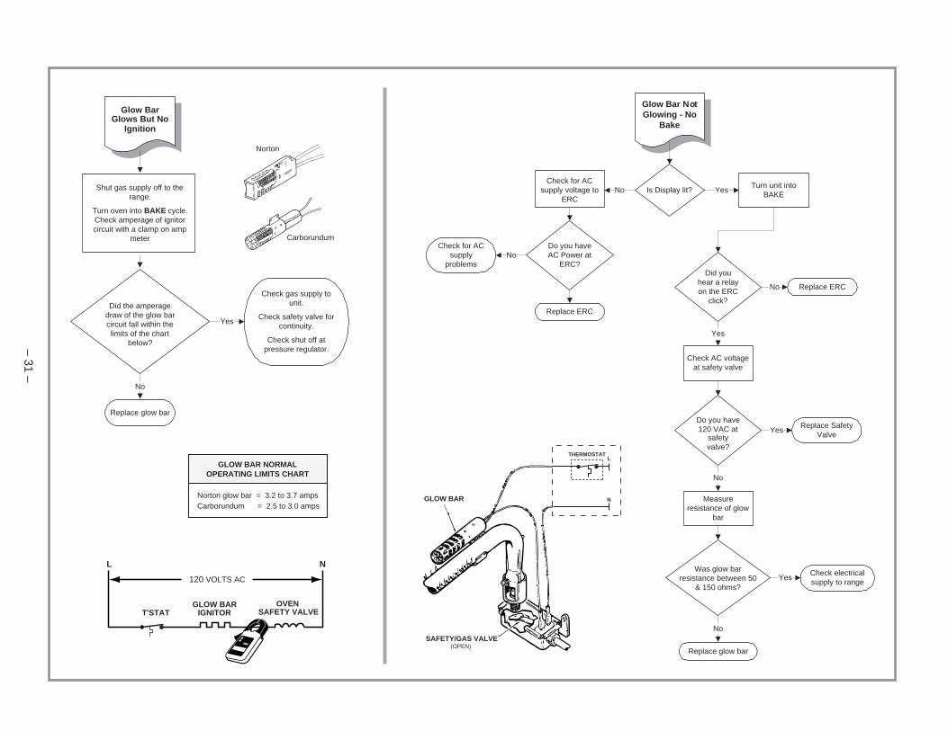
Glow BarGlows But No
Ignition
Shut gas supply off to therange.
Turn oven into BAKE cycle.Check amperage of ignitorcircuit with a clamp on amp
meter
Did the amperagedraw of the glow barcircuit fall within thelimits of the chart
below?
Yes
No
Replace glow bar
Check gas supply tounit.
Check safety valve forcontinuity.
Check shut off atpressure regulator.
Carborundum
Norton
GLOW BAR NORMALOPERATING LIMITS CHART
Norton glow bar = 3.2 to 3.7 ampsCarborundum = 2.5 to 3.0 amps
GLOW BARIGNITOR
OVENSAFETY VALVET'STAT
120 VOLTS AC
L N
Glow Bar NotGlowing - No
Bake
Is Display lit?Turn unit into
BAKE
Check for ACsupply voltage to
ERC
Do you haveAC Power at
ERC?Did you
hear a relayon the ERC
click?
Replace ERC
Check for ACsupply
problems
Check AC voltageat safety valve
Do you have120 VAC at
safetyvalve?
Replace SafetyValve
Measureresistance of glow
bar
Was glow barresistance between 50
& 150 ohms?
Check electricalsupply to range
Replace glow bar
Replace ERC
YesNo
No
Yes
Yes
No
Yes
No
No
L
N
THERMOSTAT
GLOW BAR
SAFETY/GAS VALVE(OPEN)
– 31 –
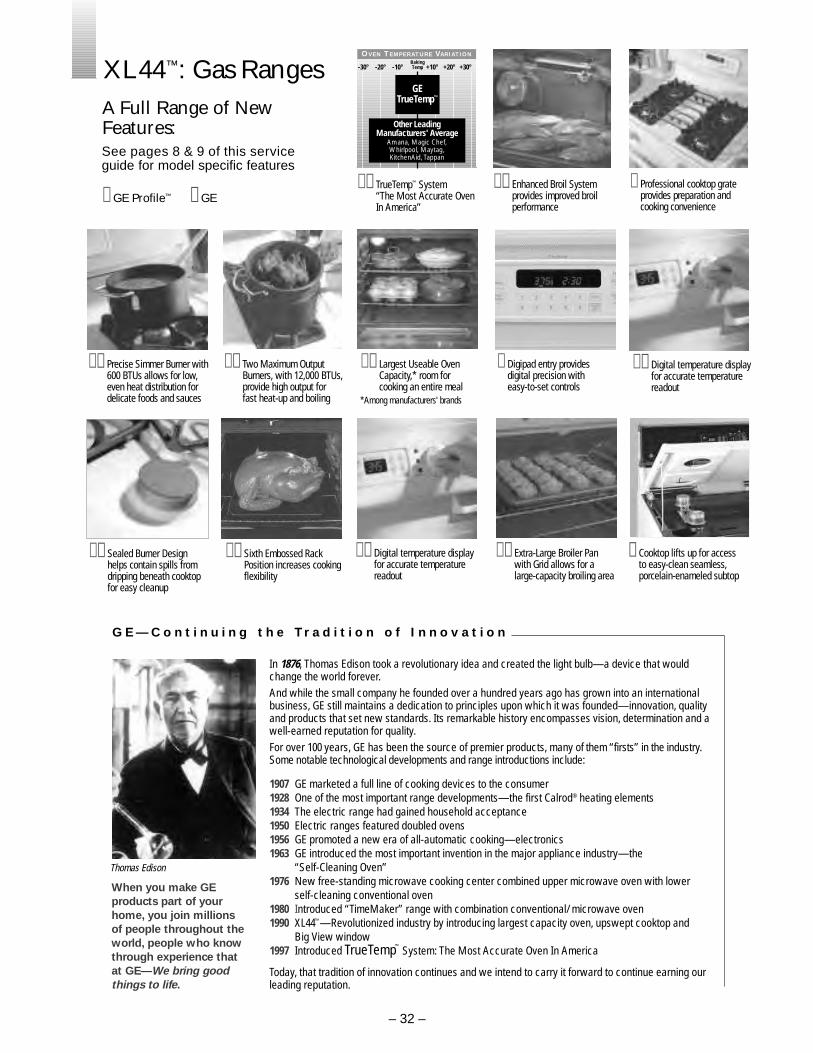
z z TrueTemp™ System “The Most Accurate Oven In America”
z Professional cooktop grateprovides preparation andcooking convenience
z z Enhanced Broil System provides improved broilperformance
Other LeadingManufacturers' Average
Amana, Magic Chef,Whirlpool, Maytag,KitchenAid, Tappan
GETrueTemp™
BakingTemp-30° -20° -10° +10° +20° +30°
OVEN TEMPERATURE VARIATION
z Digipad entry provides digital precision with easy-to-set controls
z z Largest Useable OvenCapacity,* room forcooking an entire meal
*Among manufacturers' brands
z z Two Maximum OutputBurners, with 12,000 BTUs,provide high output for fast heat-up and boiling
z z Precise Simmer Burner with600 BTUs allows for low,even heat distribution fordelicate foods and sauces
z z Digital temperature displayfor accurate temperaturereadout
z z Extra-Large Broiler Panwith Grid allows for alarge-capacity broiling area
z Cooktop lifts up for accessto easy-clean seamless,porcelain-enameled subtop
z z Digital temperature displayfor accurate temperaturereadout
z z Sixth Embossed RackPosition increases cookingflexibility
z z Sealed Burner Designhelps contain spills fromdripping beneath cooktopfor easy cleanup
Thomas Edison
When you make GEproducts part of yourhome, you join millions of people throughout theworld, people who knowthrough experience thatat GE—We bring goodthings to life.
In 1876, Thomas Edison took a revolutionary idea and created the light bulb—a device that wouldchange the world forever.And while the small company he founded over a hundred years ago has grown into an internationalbusiness, GE still maintains a dedication to principles upon which it was founded—innovation, qualityand products that set new standards. Its remarkable history encompasses vision, determination and awell-earned reputation for quality.For over 100 years, GE has been the source of premier products, many of them “firsts” in the industry.Some notable technological developments and range introductions include:
1907 GE marketed a full line of cooking devices to the consumer 1928 One of the most important range developments—the first Calrod® heating elements 1934 The electric range had gained household acceptance1950 Electric ranges featured doubled ovens1956 GE promoted a new era of all-automatic cooking—electronics1963 GE introduced the most important invention in the major appliance industry—the
“Self-Cleaning Oven”1976 New free-standing microwave cooking center combined upper microwave oven with lower
self-cleaning conventional oven1980 Introduced “TimeMaker” range with combination conventional/ microwave oven1990 XL44™—Revolutionized industry by introducing largest capacity oven, upswept cooktop and
Big View window1997 Introduced TrueTemp™ System: The Most Accurate Oven In America
Today, that tradition of innovation continues and we intend to carry it forward to continue earning ourleading reputation.
G E — C o n t i n u i n g t h e Tr a d i t i o n o f I n n o v a t i o n
XL44™: Gas RangesA Full Range of NewFeatures:See pages 8 & 9 of this service guide for model specific features
z GE Profile™ z GE
– 32 –