technical solutions for creepfeed grinding … · technical solutions for creepfeed grinding...
TRANSCRIPT
IN THE AEROSPACE & TURBINE MARKETS
TECHNICAL SOLUTIONS FOR
CREEPFEED GRINDING
TECHNICAL GUIDE
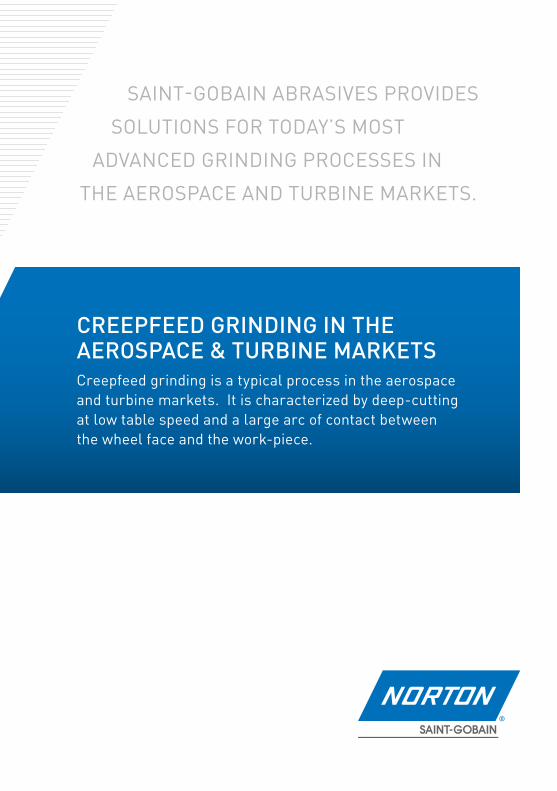
SAINT-GOBAIN ABRASIVES PROVIDES
SOLUTIONS FOR TODAY’S MOST
ADVANCED GRINDING PROCESSES IN
THE AEROSPACE AND TURBINE MARKETS.
CREEPFEED GRINDING IN THE AEROSPACE & TURBINE MARKETS Creepfeed grinding is a typical process in the aerospace and turbine markets. It is characterized by deep-cutting at low table speed and a large arc of contact between the wheel face and the work-piece.
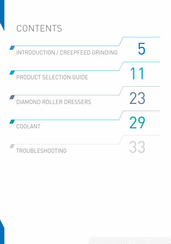
INTRODUCTION / CREEPFEED GRINDING 5PRODUCT SELECTION GUIDE 11DIAMOND ROLLER DRESSERS 23COOLANT 29TROUBLESHOOTING 33
CONTENTS
INTRODUCTION
5CREEPFEED GRINDING
CREEPFEED GRINDING
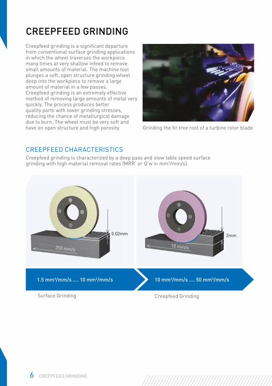
Grinding the fir tree root of a turbine rotor blade
Surface Grinding Creepfeed Grinding
Creepfeed grinding is a significant departure from conventional surface grinding applications in which the wheel traverses the workpiece many times at very shallow infeed to remove small amounts of material. The machine tool plunges a soft, open structure grinding wheel deep into the workpiece to remove a large amount of material in a few passes. Creepfeed grinding is an extremely effective method of removing large amounts of metal very quickly. The process produces better quality parts with lower grinding stresses, reducing the chance of metallurgical damage due to burn. The wheel must be very soft and have an open structure and high porosity.
CREEPFEED CHARACTERISTICSCreepfeed grinding is characterized by a deep pass and slow table speed surface grinding with high material removal rates (MRR’ or Q’w in mm3/mm/s).
0.02mm
250 mm/s
2mm
10 mm/s
1.5 mm3/mm/s .... 10 mm3/mm/s 10 mm3/mm/s .... 50 mm3/mm/s
6 CREEPFEED GRINDING
TYPICAL PARTS MACHINED
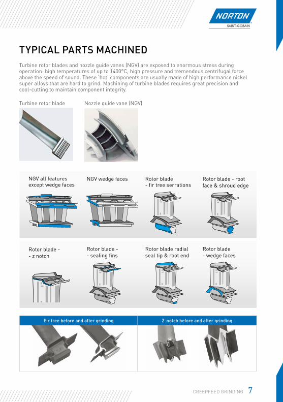
Turbine rotor blade Nozzle guide vane (NGV)
Turbine rotor blades and nozzle guide vanes (NGV) are exposed to enormous stress during operation: high temperatures of up to 1400°C, high pressure and tremendous centrifugal force above the speed of sound. These ‘hot’ components are usually made of high performance nickel super alloys that are hard to grind. Machining of turbine blades requires great precision and cool-cutting to maintain component integrity.
NGV wedge faces
Rotor blade - fir tree serrations
Rotor blade - root face & shroud edge
NGV all featuresexcept wedge faces
Rotor blade - - z notch
Rotor blade -- sealing fins
Rotor blade radial seal tip & root end
Rotor blade - wedge faces
Fir tree before and after grinding Z-notch before and after grinding
7CREEPFEED GRINDING
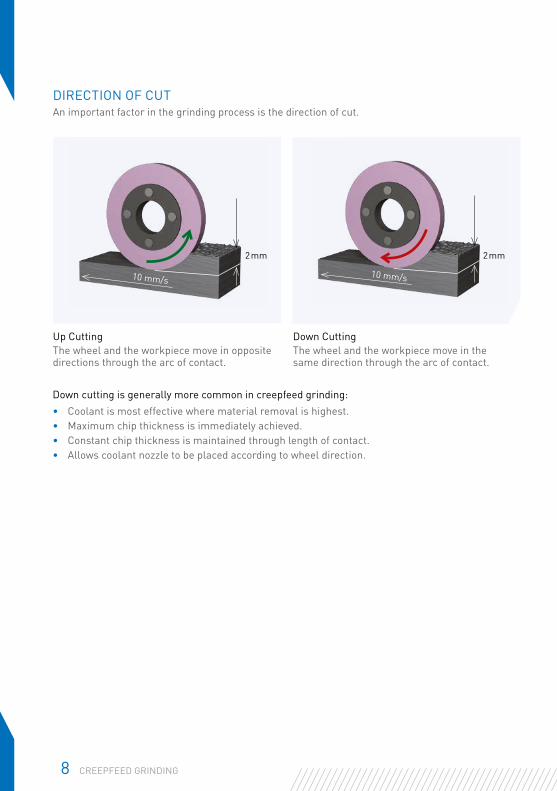
DIRECTION OF CUTAn important factor in the grinding process is the direction of cut.
Up Cutting The wheel and the workpiece move in opposite directions through the arc of contact.
Down Cutting The wheel and the workpiece move in the same direction through the arc of contact.
2mm
10 mm/s10 mm/s
Down cutting is generally more common in creepfeed grinding:• Coolant is most effective where material removal is highest.• Maximum chip thickness is immediately achieved.• Constant chip thickness is maintained through length of contact.• Allows coolant nozzle to be placed according to wheel direction.
8 CREEPFEED GRINDING
2mm
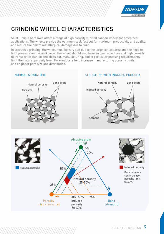
Abrasive grain (cutting)
Bond (strength)
Induced porosity 50-60%
Natural porosity 25-50%
Porosity (chip clearance)
60% 50% 25%
55%
35%
5%20%
Natural porosity Induced porosity
Pore inducers can increase porosity limit to 60%
GRINDING WHEEL CHARACTERISTICSSaint-Gobain Abrasives offers a range of high porosity vitrified bonded wheels for creepfeed applications. The wheels provide the optimum cool, fast cut for maximum productivity and quality, and reduce the risk of metallurgical damage due to burn.In creepfeed grinding, the wheel must be very soft due to the large contact area and the need to limit pressure on the workpiece. The wheel should also have an open structure and high porosity to transport coolant in and chips out. Manufacturing, and in particular pressing requirements, limit the natural porosity level. Pore inducers help increase manufacturing porosity limits, and engineer pore size and distribution.
NORMAL STRUCTURE
Natural porosity
Abrasive
STRUCTURE WITH INDUCED POROSITY
Bond postsBond posts Natural porosity
Induced porosity
Abrasive
9CREEPFEED GRINDING
10 CREEPFEED GRINDING
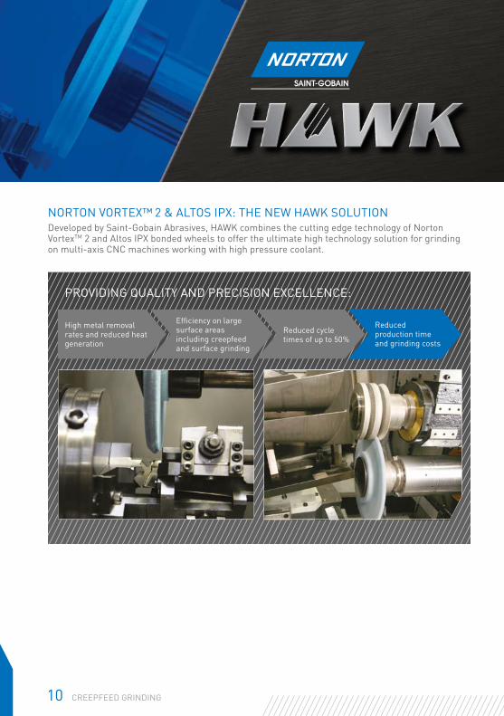
FOR THE VIPER GRINDING PROCESSNORTON VORTEX™ 2 & ALTOS IPX: THE NEW HAWK SOLUTIONDeveloped by Saint-Gobain Abrasives, HAWK combines the cutting edge technology of Norton VortexTM 2 and Altos IPX bonded wheels to offer the ultimate high technology solution for grinding on multi-axis CNC machines working with high pressure coolant.
PROVIDING QUALITY AND PRECISION EXCELLENCE:
Efficiency on large surface areas including creepfeed and surface grinding
Reduced cycle times of up to 50%
Reduced production time and grinding costs
High metal removal rates and reduced heat generation
PRODUCT SELECTION GUIDE
11PRODUCT SELECTION GUIDE
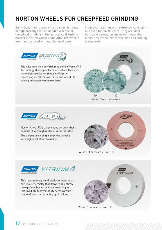
NORTON WHEELS FOR CREEPFEED GRINDINGSaint-Gobain Abrasives offers a specific range of high porosity vitrified bonded wheels for creepfeed grinding in the aerospace & turbine markets. Norton Vortex 2 and Altos IPX wheels are manufactured without chemical pore
inducers, resulting in an extremely consistent and even macrostructure. They are ideal for use in aerospace and power generation industries, where exact precision and stability is required.
Vortex 2 microstructure
Altos IPX microstructure 1:10
Vitrium3 microstructure 1:10
The advanced high performance bond in VortexTM 2 Technology, developed by Saint-Gobain Abrasives, maximises profile holding, significantly increasing metal removal rates and wheel life, raising productivity to a new level.
1:4 1:10
Norton Altos IPX is an extruded ceramic that is capable of very high material removal rates.
The unique grain shape gives the wheel a very high level of permeability.
This revolutionary bond platform features an exclusive chemistry that delivers an entirely new grain adhesion science, resulting in improved product versatility across a wide range of precision grinding applications.
12 PRODUCT SELECTION GUIDE
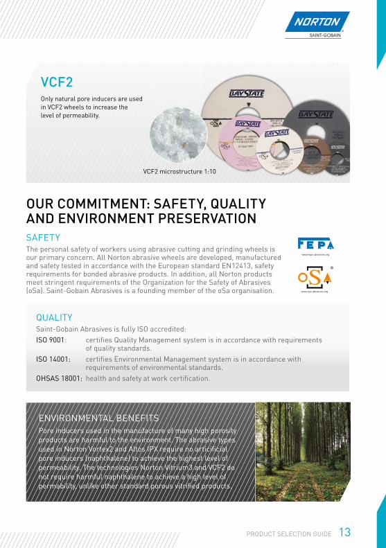
Only natural pore inducers are used in VCF2 wheels to increase the level of permeability.
VCF2
VCF2 microstructure 1:10
ENVIRONMENTAL BENEFITSPore inducers used in the manufacture of many high porosity products are harmful to the environment. The abrasive types used in Norton Vortex2 and Altos IPX require no articificial pore inducers (naphthalene) to achieve the highest level of permeability. The technologies Norton Vitrium3 and VCF2 do not require harmful naphthalene to achieve a high level of permability, unlike other standard porous vitrified products.
13PRODUCT SELECTION GUIDE
OUR COMMITMENT: SAFETY, QUALITY AND ENVIRONMENT PRESERVATIONSAFETYThe personal safety of workers using abrasive cutting and grinding wheels is our primary concern. All Norton abrasive wheels are developed, manufactured and safety tested in accordance with the European standard EN12413, safety requirements for bonded abrasive products. In addition, all Norton products meet stringent requirements of the Organization for the Safety of Abrasives (oSa). Saint-Gobain Abrasives is a founding member of the oSa organisation.
QUALITYSaint-Gobain Abrasives is fully ISO accredited:ISO 9001: certifies Quality Management system is in accordance with requirements
of quality standards.ISO 14001: certifies Environmental Management system is in accordance with
requirements of environmental standards.OHSAS 18001: health and safety at work certification.
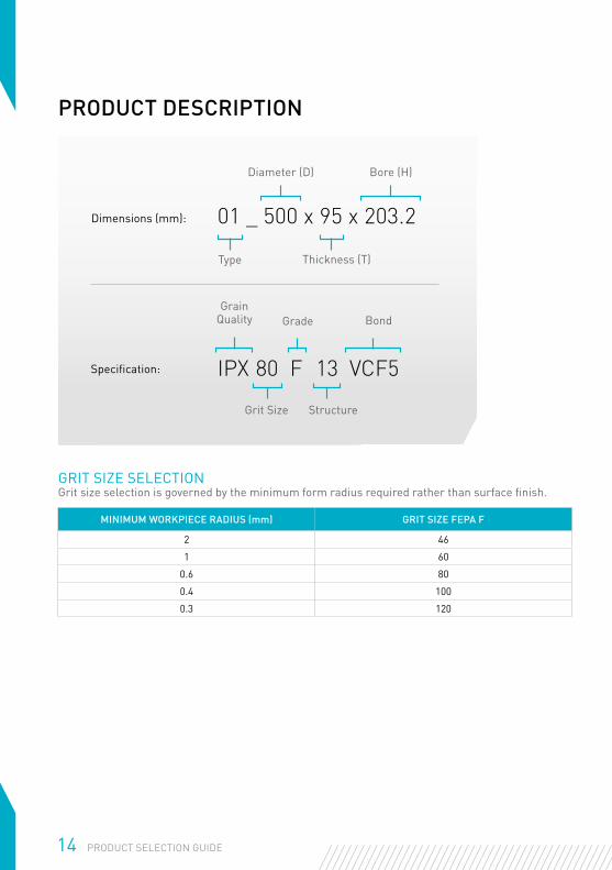
PRODUCT DESCRIPTION
MINIMUM WORKPIECE RADIUS (mm) GRIT SIZE FEPA F
2 46
1 60
0.6 80
0.4 100
0.3 120
GRIT SIZE SELECTIONGrit size selection is governed by the minimum form radius required rather than surface finish.
Type
Diameter (D)
01 _ 500 x 95 x 203.2
Thickness (T)
Bore (H)
Dimensions (mm):
GrainQuality
Grit Size Structure
IPX 80 F 13 VCF5
Bond
Specification:
Grade
14 PRODUCT SELECTION GUIDE
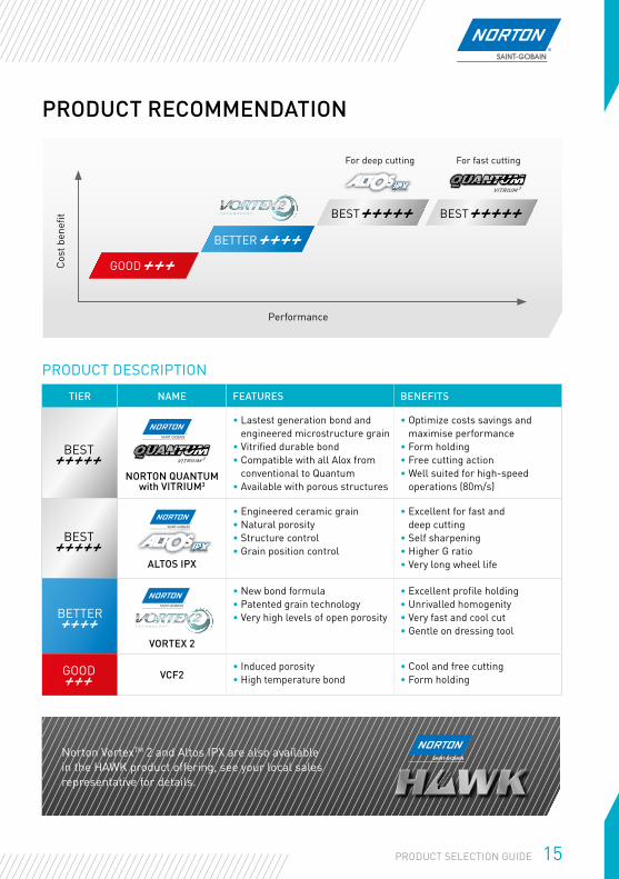
Performance
Cost
ben
efit
TIER NAME FEATURES BENEFITS
NORTON QUANTUM with VITRIUM3
• Lastest generation bond and engineered microstructure grain
• Vitrified durable bond• Compatible with all Alox from
conventional to Quantum• Available with porous structures
• Optimize costs savings and maximise performance
• Form holding• Free cutting action• Well suited for high-speed
operations (80m/s)
ALTOS IPX
• Engineered ceramic grain • Natural porosity• Structure control• Grain position control
• Excellent for fast and deep cutting
• Self sharpening• Higher G ratio• Very long wheel life
VORTEX 2
• New bond formula• Patented grain technology• Very high levels of open porosity
• Excellent profile holding• Unrivalled homogenity• Very fast and cool cut• Gentle on dressing tool
VCF2• Induced porosity• High temperature bond
• Cool and free cutting• Form holding
PRODUCT DESCRIPTION
BEST
BEST
T E C H N O L O G Y
TM
GOOD
BETTER
PRODUCT RECOMMENDATION
Norton VortexTM 2 and Altos IPX are also available in the HAWK product offering, see your local sales representative for details.
BEST BEST
BETTER
GOOD
For deep cutting For fast cutting
T E C H N O L O G Y
TM
15PRODUCT SELECTION GUIDE
MACHINE BRAND / MODEL
ABA
BLO
HM
DAN
OB
AT
ELB
HAA
S
JON
ES &
SH
IPM
AN
MÄG
ERLE
MAK
INO
Easy
line
/ Eco
line
Mut
lilin
e &
Pow
erlin
e
Profi
mat
MC
/ MT
/ RT
Plan
omat
HP
Prok
os
MC
/ MT
Mic
ro-C
ut
Mul
tigri
nd C
A / C
B
Dom
inat
or 6
24/6
34/6
44
MFP
/ M
FR /
MFS
A99ε
iG5
/ iG
7
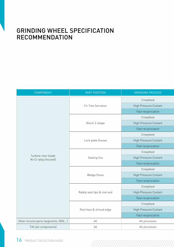
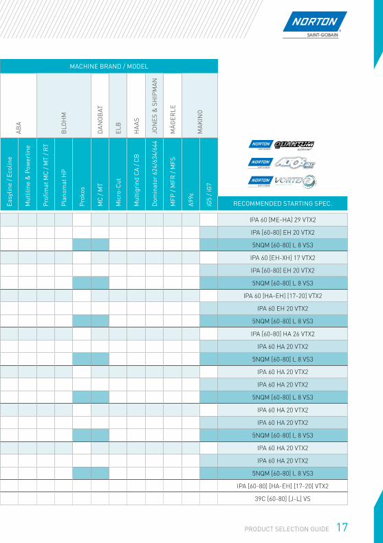
COMPONENT PART POSITION GRINDING PROCESS RECOMMENDED STARTING SPEC.
Turbine rotor bladeNi-Cr alloy (Inconel)
Fir Tree Serration
Creepfeed IPA 60 [ME-HA] 29 VTX2
High Pressure Coolant IPA [60-80] EH 20 VTX2
Fast reciprocation 5NQM [60-80] L 8 VS3
Notch Z shape
Creepfeed IPA 60 [EH-XH] 17 VTX2
High Pressure Coolant IPA [60-80] EH 20 VTX2
Fast reciprocation 5NQM [60-80] L 8 VS3
Lock plate Groove
Creepfeed IPA 60 [HA-EH] [17-20] VTX2
High Pressure Coolant IPA 60 EH 20 VTX2
Fast reciprocation 5NQM [60-80] L 8 VS3
Sealing fins
Creepfeed IPA [60-80] HA 26 VTX2
High Pressure Coolant IPA 60 HA 20 VTX2
Fast reciprocation 5NQM [60-80] L 8 VS3
Wedge Faces
Creepfeed IPA 60 HA 20 VTX2
High Pressure Coolant IPA 60 HA 20 VTX2
Fast reciprocation 5NQM [60-80] L 8 VS3
Radial seal tips & root end
Creepfeed IPA 60 HA 20 VTX2
High Pressure Coolant IPA 60 HA 20 VTX2
Fast reciprocation 5NQM [60-80] L 8 VS3
Root face & shroud edge
Creepfeed IPA 60 HA 20 VTX2
High Pressure Coolant IPA 60 HA 20 VTX2
Fast reciprocation 5NQM [60-80] L 8 VS3
Other Inconel parts (segments, NGV,…) All All processes IPA [60-80] [HA-EH] [17-20] VTX2
TiAl (all components) All All processes 39C [60-80] [J-L] VS
GRINDING WHEEL SPECIFICATION RECOMMENDATION
16 PRODUCT SELECTION GUIDE
MACHINE BRAND / MODEL
ABA
BLO
HM
DAN
OB
AT
ELB
HAA
S
JON
ES &
SH
IPM
AN
MÄG
ERLE
MAK
INO
Easy
line
/ Eco
line
Mut
lilin
e &
Pow
erlin
e
Profi
mat
MC
/ MT
/ RT
Plan
omat
HP
Prok
os
MC
/ MT
Mic
ro-C
ut
Mul
tigri
nd C
A / C
B
Dom
inat
or 6
24/6
34/6
44
MFP
/ M
FR /
MFS
A99ε
iG5
/ iG
7COMPONENT PART POSITION GRINDING PROCESS RECOMMENDED STARTING SPEC.
Turbine rotor bladeNi-Cr alloy (Inconel)
Fir Tree Serration
Creepfeed IPA 60 [ME-HA] 29 VTX2
High Pressure Coolant IPA [60-80] EH 20 VTX2
Fast reciprocation 5NQM [60-80] L 8 VS3
Notch Z shape
Creepfeed IPA 60 [EH-XH] 17 VTX2
High Pressure Coolant IPA [60-80] EH 20 VTX2
Fast reciprocation 5NQM [60-80] L 8 VS3
Lock plate Groove
Creepfeed IPA 60 [HA-EH] [17-20] VTX2
High Pressure Coolant IPA 60 EH 20 VTX2
Fast reciprocation 5NQM [60-80] L 8 VS3
Sealing fins
Creepfeed IPA [60-80] HA 26 VTX2
High Pressure Coolant IPA 60 HA 20 VTX2
Fast reciprocation 5NQM [60-80] L 8 VS3
Wedge Faces
Creepfeed IPA 60 HA 20 VTX2
High Pressure Coolant IPA 60 HA 20 VTX2
Fast reciprocation 5NQM [60-80] L 8 VS3
Radial seal tips & root end
Creepfeed IPA 60 HA 20 VTX2
High Pressure Coolant IPA 60 HA 20 VTX2
Fast reciprocation 5NQM [60-80] L 8 VS3
Root face & shroud edge
Creepfeed IPA 60 HA 20 VTX2
High Pressure Coolant IPA 60 HA 20 VTX2
Fast reciprocation 5NQM [60-80] L 8 VS3
Other Inconel parts (segments, NGV,…) All All processes IPA [60-80] [HA-EH] [17-20] VTX2
TiAl (all components) All All processes 39C [60-80] [J-L] VS
17PRODUCT SELECTION GUIDE
18 PRODUCT SELECTION GUIDE
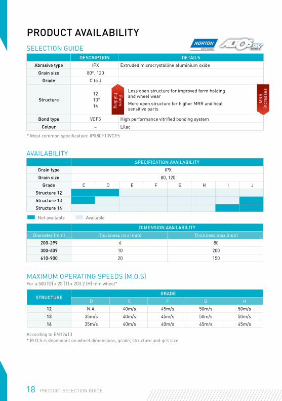
PRODUCT AVAILABILITYSELECTION GUIDE
DESCRIPTION DETAILS
Abrasive type IPX Extruded microcrystalline aluminium oxide
Grain size 80*, 120
Grade C to J
Structure12
13* 14
Less open structure for improved form holding and wheel wearMore open structure for higher MRR and heat sensitive parts
Bond type VCF5 High performance vitrified bonding system
Colour – Lilac
* Most common specification: IPX80F13VCF5
According to EN12413* M.O.S is dependant on wheel dimensions, grade, structure and grit size
SPECIFICATION AVAILABILITY
Grain type IPX
Grain size 80, 120
Grade C D E F G H I J
Structure 12
Structure 13
Structure 14
Not available Available
STRUCTUREGRADE
D E F G H
12 N.A. 40m/s 45m/s 50m/s 50m/s
13 35m/s 40m/s 45m/s 50m/s 50m/s
14 35m/s 40m/s 40m/s 45m/s 45m/s
MAXIMUM OPERATING SPEEDS (M.O.S)For a 500 (D) x 25 (T) x 203.2 (H) mm wheel*
DIMENSION AVAILABILITY
Diameter (mm) Thickness min (mm) Thickness max (mm)
200-299 6 80
300-609 10 200
610-900 20 150
AVAILABILITYForm
holding M
RR
in
crea
ses
19PRODUCT SELECTION GUIDE
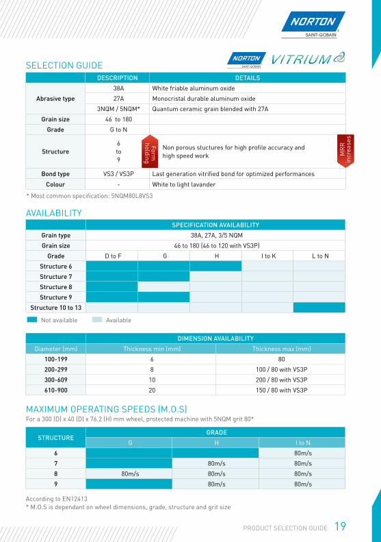
SELECTION GUIDEDESCRIPTION DETAILS
Abrasive type
38A White friable aluminum oxide
27A Monocristal durable aluminum oxide
3NQM / 5NQM* Quantum ceramic grain blended with 27A
Grain size 46 to 180
Grade G to N
Structure6 to 9
Non porous stuctures for high profile accuracy and high speed work
Bond type VS3 / VS3P Last generation vitrified bond for optimized performances
Colour - White to light lavander
* Most common specification: 5NQM80L8VS3
According to EN12413* M.O.S is dependant on wheel dimensions, grade, structure and grit size
SPECIFICATION AVAILABILITY
Grain type 38A, 27A, 3/5 NQM
Grain size 46 to 180 (46 to 120 with VS3P)
Grade D to F G H I to K L to N
Structure 6
Structure 7
Structure 8
Structure 9
Structure 10 to 13
Not available Available
STRUCTUREGRADE
G H I to N
6 80m/s
7 80m/s 80m/s
8 80m/s 80m/s 80m/s
9 80m/s 80m/s
MAXIMUM OPERATING SPEEDS (M.O.S)For a 300 (D) x 40 (D) x 76.2 (H) mm wheel, protected machine with 5NQM grit 80*
DIMENSION AVAILABILITY
Diameter (mm) Thickness min (mm) Thickness max (mm)
100-199 6 80
200-299 8 100 / 80 with VS3P
300-609 10 200 / 80 with VS3P
610-900 20 150 / 80 with VS3P
AVAILABILITYForm
holding
MR
R
incr
ease
s
20 PRODUCT SELECTION GUIDE
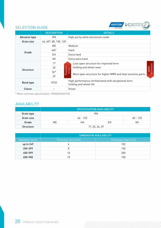
SELECTION GUIDE
* Most common specification: IPA60HA26VTX2
SPECIFICATION AVAILABILITY
Grain type IPA
Grain size 46 - 120 60 - 120
Grade ME HA EH XH
Structure 17, 20, 26, 29
DIMENSION AVAILABILITY
Diameter (mm) Thickness min (mm) Thickness max (mm)
up to 249 6 102
250-399 8 150
400-599 10 300
600-900 15 150
AVAILABILITY
DESCRIPTION DETAILS
Abrasive type IPA High purity white aluminium oxide
Grain size 46, 60*, 80, 100, 120
Grade
ME Medium
HA* Hard
EH Extra hard
XH Extra extra hard
Structure
17 Less open structure for improved formholding and wheel wear20
26*More open structure for higher MRR and heat sensitive parts
29
Bond type VTX2High performance vitrified bond with exceptional form holding and wheel life
Colour – GreenForm
holding
MR
R
incr
ease
s
STRUCTURE 1ST NUMBER
STRUCTURE 2ND NUMBER (POROSITY)
GRADE
F G H I J K L
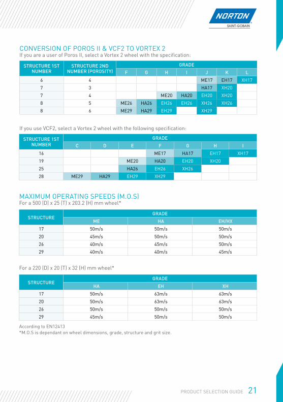
6 4 ME17 EH17 XH17
7 3 HA17 XH20
7 4 ME20 HA20 EH20 XH20
8 5 ME26 HA26 EH26 EH26 XH26 XH26
8 6 ME29 HA29 EH29 XH29
STRUCTURE 1ST NUMBER
GRADE
C D E F G H I
16 ME17 HA17 EH17 XH17
19 ME20 HA20 EH20 XH20
25 HA26 EH26 XH26
28 ME29 HA29 EH29 XH29
STRUCTUREGRADE
ME HA EH/HX
17 50m/s 50m/s 50m/s
20 45m/s 50m/s 50m/s
26 40m/s 45m/s 50m/s
29 40m/s 40m/s 45m/s
STRUCTUREGRADE
HA EH XH
17 50m/s 63m/s 63m/s
20 50m/s 63m/s 63m/s
26 50m/s 50m/s 50m/s
29 45m/s 50m/s 50m/s
If you use VCF2, select a Vortex 2 wheel with the following specification:
According to EN12413 *M.O.S is dependant on wheel dimensions, grade, structure and grit size.
CONVERSION OF POROS II & VCF2 TO VORTEX 2If you are a user of Poros II, select a Vortex 2 wheel with the specification:
MAXIMUM OPERATING SPEEDS (M.O.S)For a 500 (D) x 25 (T) x 203.2 (H) mm wheel*
For a 220 (D) x 20 (T) x 32 (H) mm wheel*
21PRODUCT SELECTION GUIDE
22 PRODUCT SELECTION GUIDE
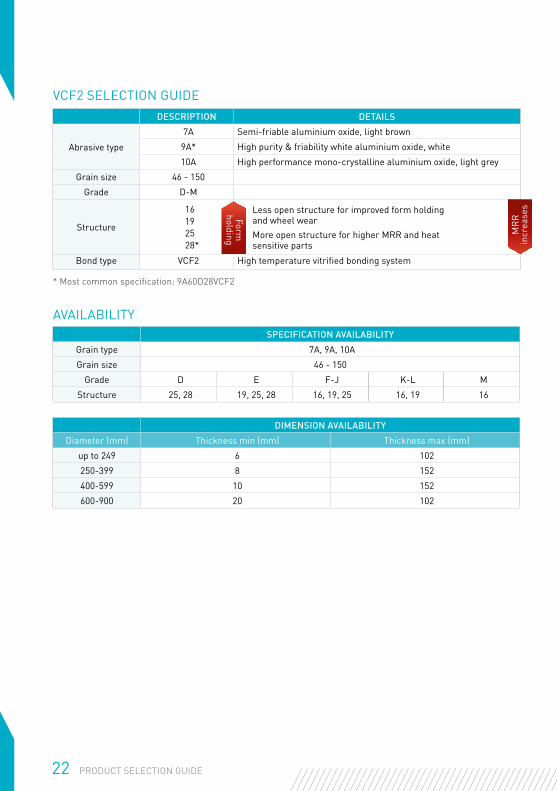
DESCRIPTION DETAILS
Abrasive type
7A Semi-friable aluminium oxide, light brown
9A* High purity & friability white aluminium oxide, white
10A High performance mono-crystalline aluminium oxide, light grey
Grain size 46 - 150
Grade D-M
Structure
16192528*
Less open structure for improved form holding and wheel wearMore open structure for higher MRR and heat sensitive parts
Bond type VCF2 High temperature vitrified bonding system
* Most common specification: 9A60D28VCF2
AVAILABILITY
VCF2 SELECTION GUIDE
DIMENSION AVAILABILITY
Diameter (mm) Thickness min (mm) Thickness max (mm)
up to 249 6 102
250-399 8 152
400-599 10 152
600-900 20 102
SPECIFICATION AVAILABILITY
Grain type 7A, 9A, 10A
Grain size 46 - 150
Grade D E F-J K-L M
Structure 25, 28 19, 25, 28 16, 19, 25 16, 19 16
Form
holding MR
R
incr
ease
s
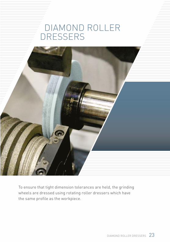
To ensure that tight dimension tolerances are held, the grinding wheels are dressed using rotating roller dressers which have the same profile as the workpiece.
DIAMOND ROLLER DRESSERS
23DIAMOND ROLLER DRESSERS
24 DIAMOND ROLLER DRESSERS
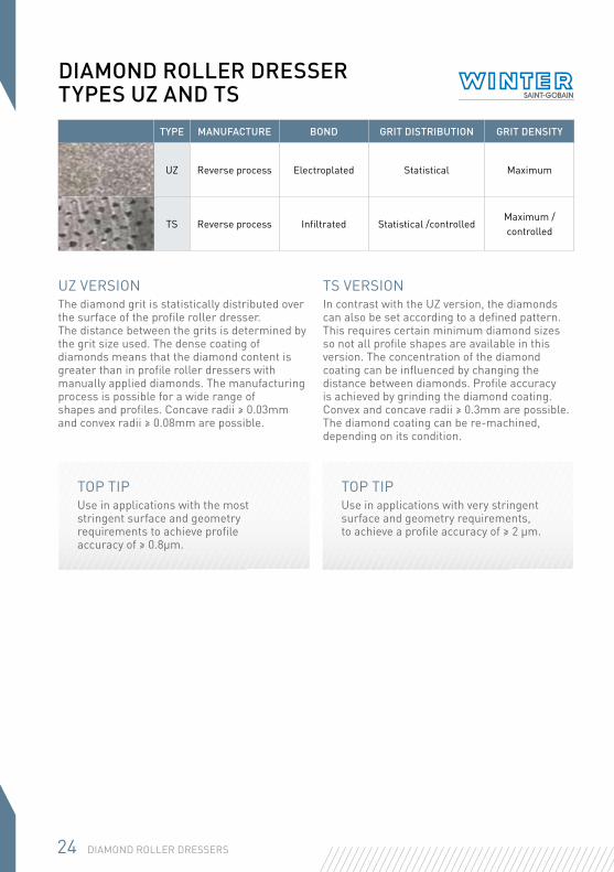
DIAMOND ROLLER DRESSER TYPES UZ AND TS
TYPE MANUFACTURE BOND GRIT DISTRIBUTION GRIT DENSITY
UZ Reverse process Electroplated Statistical Maximum
TS Reverse process Infiltrated Statistical /controlled Maximum /controlled
UZ VERSIONThe diamond grit is statistically distributed over the surface of the profile roller dresser. The distance between the grits is determined by the grit size used. The dense coating of diamonds means that the diamond content is greater than in profile roller dressers with manually applied diamonds. The manufacturing process is possible for a wide range of shapes and profiles. Concave radii ≥ 0.03mm and convex radii ≥ 0.08mm are possible.
TS VERSIONIn contrast with the UZ version, the diamonds can also be set according to a defined pattern. This requires certain minimum diamond sizes so not all profile shapes are available in this version. The concentration of the diamond coating can be influenced by changing the distance between diamonds. Profile accuracy is achieved by grinding the diamond coating. Convex and concave radii ≥ 0.3mm are possible. The diamond coating can be re-machined, depending on its condition.
TOP TIPUse in applications with the most stringent surface and geometry requirements to achieve profile accuracy of ≥ 0.8µm.
TOP TIPUse in applications with very stringent surface and geometry requirements, to achieve a profile accuracy of ≥ 2 μm.
25DIAMOND ROLLER DRESSERS
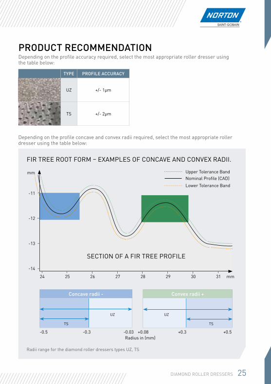
PRODUCT RECOMMENDATIONDepending on the profile accuracy required, select the most appropriate roller dresser using the table below:
FIR TREE ROOT FORM – EXAMPLES OF CONCAVE AND CONVEX RADII.
Depending on the profile concave and convex radii required, select the most appropriate roller dresser using the table below:
Radii range for the diamond roller dressers types UZ, TS
-11
-12
-13
-14
24 31302928272625
Upper Tolerance BandNominal Profile (CAD)Lower Tolerance Band
Concave radii -
TS
UZ
Convex radii +
UZ
TS
-0.5 -0.3 -0.03 +0.08 +0.3 +0.5Radius in (mm)
mm
mm
TYPE PROFILE ACCURACY
UZ +/- 1µm
TS +/- 2µm
SECTION OF A FIR TREE PROFILE
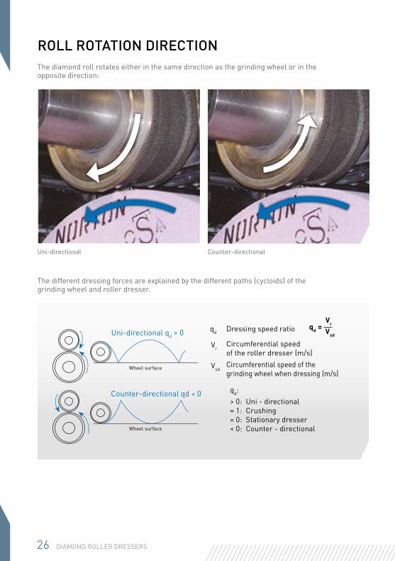
ROLL ROTATION DIRECTIONThe diamond roll rotates either in the same direction as the grinding wheel or in the opposite direction:
Uni-directional Counter-directional
The different dressing forces are explained by the different paths (cycloids) of the grinding wheel and roller dresser.
Uni-directional qd > 0
Counter-directional qd < 0> 0: Uni - directional= 1: Crushing= 0: Stationary dresser< 0: Counter - directionalWheel surface
Wheel surface
qd Dressing speed ratio
VrCircumferential speed of the roller dresser (m/s)
VsdCircumferential speed of the grinding wheel when dressing (m/s)
qd:
Vsd
qd = Vr
26 DIAMOND ROLLER DRESSERS
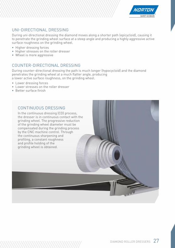
UNI-DIRECTIONAL DRESSINGDuring uni-directional dressing the diamond moves along a shorter path (epicycloid), causing it to penetrate the grinding wheel surface at a steep angle and producing a highly aggressive active surface roughness on the grinding wheel.• Higher dressing forces• Higher stresses on the roller dresser• Wheel is more aggressive
COUNTER-DIRECTIONAL DRESSINGDuring counter-directional dressing the path is much longer (hypocycloid) and the diamond penetrates the grinding wheel at a much flatter angle, producing a lower active surface roughness, on the grinding wheel.• Lower dressing forces• Lower stresses on the roller dresser• Better surface finish
CONTINUOUS DRESSINGIn the continuous dressing (CD) process, the dresser is in continuous contact with the grinding wheel. The progressive reduction of the grinding wheel diameter must be compensated during the grinding process by the CNC machine control. Through the continuous sharpening and profiling, a constant roughness and profile holding of the grinding wheel is obtained.
27DIAMOND ROLLER DRESSERS
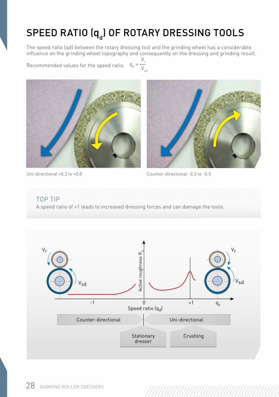
SPEED RATIO (qd) OF ROTARY DRESSING TOOLSThe speed ratio (qd) between the rotary dressing tool and the grinding wheel has a considerable influence on the grinding wheel topography and consequently on the dressing and grinding result.
Recommended values for the speed ratio,
Uni-directional +0.3 to +0.8 Counter-directional -0.3 to -0.5
Vsd
qd = Vr
TOP TIPA speed ratio of +1 leads to increased dressing forces and can damage the tools.
Vr Vr
Vsd
-1 0 +1 qd
Vsd
Uni-directionalCounter-directional
Stationary dresser
Crushing
Speed ratio (qd)
Activ
e ro
ughn
ess
Rts
28 DIAMOND ROLLER DRESSERS
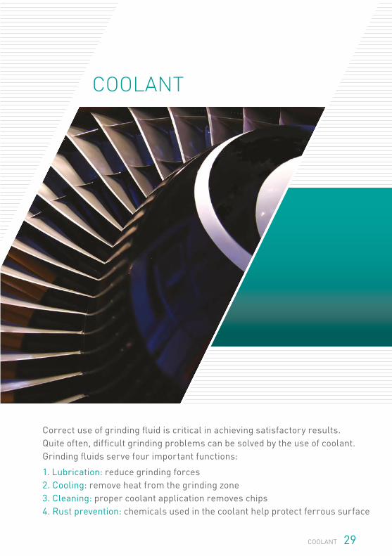
Correct use of grinding fluid is critical in achieving satisfactory results. Quite often, difficult grinding problems can be solved by the use of coolant. Grinding fluids serve four important functions:
1. Lubrication: reduce grinding forces 2. Cooling: remove heat from the grinding zone 3. Cleaning: proper coolant application removes chips 4. Rust prevention: chemicals used in the coolant help protect ferrous surface
COOLANT
29COOLANT
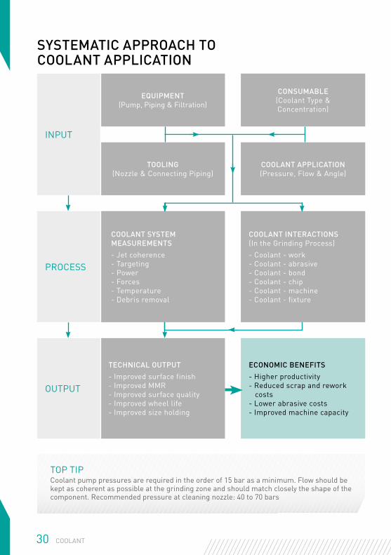
INPUT
EQUIPMENT(Pump, Piping & Filtration)
CONSUMABLE(Coolant Type & Concentration)
TOOLING(Nozzle & Connecting Piping)
COOLANT APPLICATION(Pressure, Flow & Angle)
PROCESS
COOLANT SYSTEM MEASUREMENTS- Jet coherence- Targeting- Power- Forces- Temperature- Debris removal
COOLANT INTERACTIONS(In the Grinding Process)- Coolant - work- Coolant - abrasive- Coolant - bond- Coolant - chip- Coolant - machine- Coolant - fixture
OUTPUT
TECHNICAL OUTPUT- Improved surface finish- Improved MMR- Improved surface quality- Improved wheel life- Improved size holding
ECONOMIC BENEFITS- Higher productivity- Reduced scrap and rework costs- Lower abrasive costs- Improved machine capacity
30 COOLANT
SYSTEMATIC APPROACH TO COOLANT APPLICATION
TOP TIPCoolant pump pressures are required in the order of 15 bar as a minimum. Flow should be kept as coherent as possible at the grinding zone and should match closely the shape of the component. Recommended pressure at cleaning nozzle: 40 to 70 bars
31COOLANT
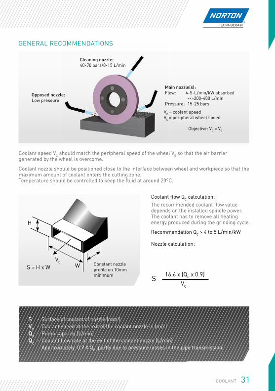
S - Surface of coolant of nozzle (mm2)VC - Coolant speed at the exit of the coolant nozzle in (m/s)QP - Pump capacity (L/min)QC - Coolant flow rate at the exit of the coolant nozzle (L/min)
Approximately 0.9 X QP (partly due to pressure losses in the pipe transmission)
Coolant flow QC calculation: The recommended coolant flow value depends on the installed spindle power. The coolant has to remove all heating energy produced during the grinding cycle.
Recommendation QC > 4 to 5 L/min/kW Nozzle calculation:
S = 16.6 x (QP x 0.9)
VC
GENERAL RECOMMENDATIONS
Coolant speed VC should match the peripheral speed of the wheel VS so that the air barrier generated by the wheel is overcome.
Coolant nozzle should be positioned close to the interface between wheel and workpiece so that the maximum amount of coolant enters the cutting zone.Temperature should be controlled to keep the fluid at around 20ºC.
Cleaning nozzle: 40-70 bars/8-15 L/min
Opposed nozzle: Low pressure
Main nozzle(s): Flow: 4-5-L/min/kW absorbed -->200-400 L/min Pressure: 15-25 bars
VC = coolant speed VS = peripheral wheel speed
Objective: VC = VS
Constant nozzleprofile on 10mm minimum
S = H x WVC
W
H
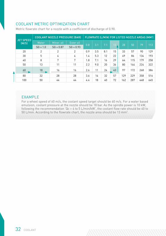
JET SPEED (M/S)
COOLANT NOZZLE PRESSURE (BAR) FLOWRATE (L/MIN) FOR LISTED NOZZLE AREAS (MM2)
Water Miner. oil Ester oil0.8 3.1 7.1 13 28 50 79 113
SG = 1.0 SG = 0.87 SG = 0.9320 2 2 2 0.9 3.5 8.1 15 33 57 90 12930 5 4 4 1.4 5.3 12 22 49 86 134 19340 8 7 7 1.8 7.1 16 29 64 115 179 25850 13 11 11 2.2 9.0 20 36 80 144 224 322
60 18 16 16 2.6 11 24 43 97 172 268 386
80 32 28 28 3.6 14 32 57 129 229 358 516100 50 44 44 4.4 18 40 72 162 287 448 645
COOLANT METRIC OPTIMIZATION CHARTMetric flowrate chart for a nozzle with a coefficient of discharge of 0.90.
EXAMPLEFor a wheel speed of 60 m/s, the coolant speed target should be 60 m/s. For a water based emulsion, coolant pressure at the nozzle should be 18 bar. As the spindle power is 10 kW, following the recommendation ‘Qc > 4 to 5 L/min/kW’, the coolant flow rate should be 40 to 50 L/min. According to the flowrate chart, the nozzle area should be 13 mm2.
32 COOLANT
TROUBLESHOOTING
33TROUBLESHOOTING
34 TROUBLESHOOTING
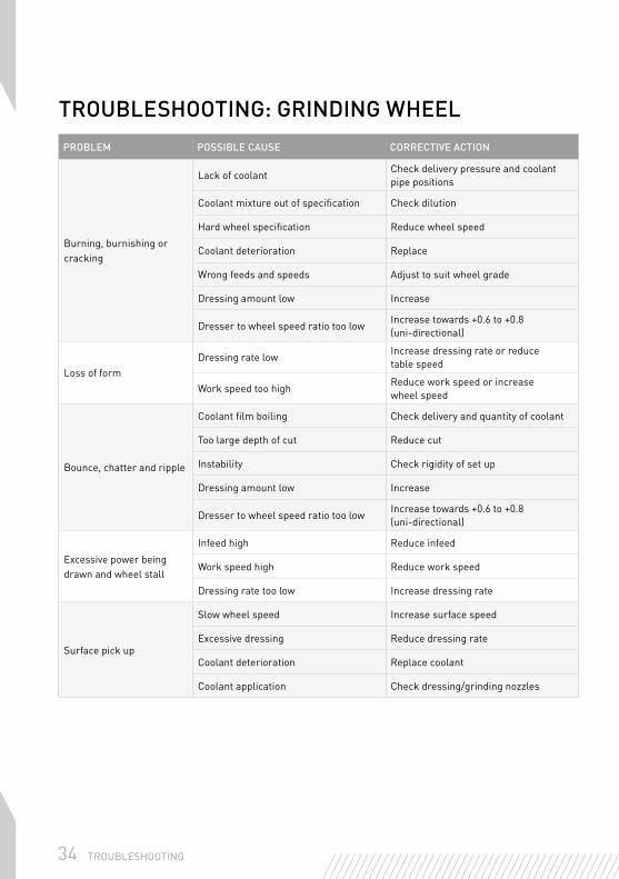
TROUBLESHOOTING: GRINDING WHEELPROBLEM POSSIBLE CAUSE CORRECTIVE ACTION
Burning, burnishing or cracking
Lack of coolantCheck delivery pressure and coolant pipe positions
Coolant mixture out of specification Check dilution
Hard wheel specification Reduce wheel speed
Coolant deterioration Replace
Wrong feeds and speeds Adjust to suit wheel grade
Dressing amount low Increase
Dresser to wheel speed ratio too lowIncrease towards +0.6 to +0.8 (uni-directional)
Loss of formDressing rate low
Increase dressing rate or reduce table speed
Work speed too highReduce work speed or increase wheel speed
Bounce, chatter and ripple
Coolant film boiling Check delivery and quantity of coolant
Too large depth of cut Reduce cut
Instability Check rigidity of set up
Dressing amount low Increase
Dresser to wheel speed ratio too lowIncrease towards +0.6 to +0.8 (uni-directional)
Excessive power being drawn and wheel stall
Infeed high Reduce infeed
Work speed high Reduce work speed
Dressing rate too low Increase dressing rate
Surface pick up
Slow wheel speed Increase surface speed
Excessive dressing Reduce dressing rate
Coolant deterioration Replace coolant
Coolant application Check dressing/grinding nozzles
35TROUBLESHOOTING
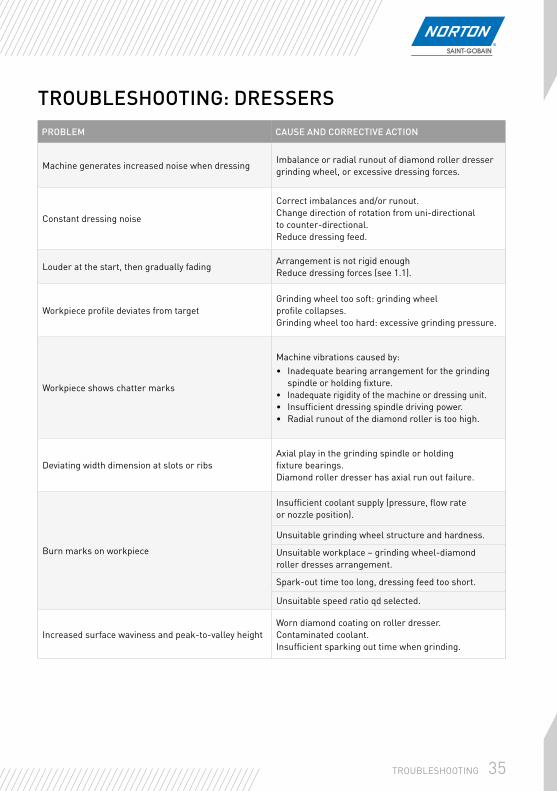
TROUBLESHOOTING: DRESSERSPROBLEM CAUSE AND CORRECTIVE ACTION
Machine generates increased noise when dressingImbalance or radial runout of diamond roller dresser grinding wheel, or excessive dressing forces.
Constant dressing noise
Correct imbalances and/or runout.Change direction of rotation from uni-directional to counter-directional.Reduce dressing feed.
Louder at the start, then gradually fadingArrangement is not rigid enoughReduce dressing forces (see 1.1).
Workpiece profile deviates from targetGrinding wheel too soft: grinding wheel profile collapses. Grinding wheel too hard: excessive grinding pressure.
Workpiece shows chatter marks
Machine vibrations caused by:• Inadequate bearing arrangement for the grinding
spindle or holding fixture.• Inadequate rigidity of the machine or dressing unit.• Insufficient dressing spindle driving power.• Radial runout of the diamond roller is too high.
Deviating width dimension at slots or ribs Axial play in the grinding spindle or holding fixture bearings.Diamond roller dresser has axial run out failure.
Burn marks on workpiece
Insufficient coolant supply (pressure, flow rate or nozzle position).
Unsuitable grinding wheel structure and hardness.
Unsuitable workplace – grinding wheel-diamond roller dresses arrangement.
Spark-out time too long, dressing feed too short.
Unsuitable speed ratio qd selected.
Increased surface waviness and peak-to-valley heightWorn diamond coating on roller dresser.Contaminated coolant.Insufficient sparking out time when grinding.
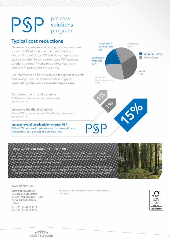
Decreasing the price of abrasivesA 30% price reduction will only reduce costs per part by 1%.
Typical cost reductionsOn average abrasives and cutting tools only account for about 3% of total manufacturing budgets. Norton Vitrium3, Altos IPX and Vortex 2 products optimised with Norton’s proprietary PSP (process solutions program) helps to optimise your total cost and improve your productivity.
For information on how to achieve the greatest overall cost savings, see the example below or go to www.saint-gobain-abrasives.com/psp-eu.aspx.
15%1%
1%
Increase overall productivity through PSPWith a 20% decrease in cycle time per part there will be a reduced total cost per part of more than 15%.
Increasing the life of abrasivesEven a 50% increase in product life will only reduce costs per part by 1%.
Machinery27%
Labour31%
Abrasives & cutting tools3%
Buildings & administration22%
Workpiecematerials17%
Variable CostsFixed Costs
IMPROVING OUR CARBON FOOTPRINTIncreased productivity with existing customer machine capacity. Able to work with higher feed rates, speed and pressure, to significantly increase production while using fewer wheels.Reduced energy consumption with optimal firing temperatures during manufacturing of Norton Vitrium3, Altos IPX and Vortex 2 wheels.
By choosing Norton Vitrium3, Altos IPX and Vortex 2 technology for your grinding operation, you help to preserve the environment. In addition, Norton Vitrium3, Altos and Vortex 2 eliminate costly re-validation of processes associated with using chemical pore inducers such as naphthalene.
Norton is a registered trademark of Saint-Gobain Abrasives.Form # 2596
www.norton.euSaint-Gobain AbrasifsEuropean HeadquartersRue de l’Ambassadeur - B.P.878 702 Conflans Cedex France
Tel: +33 (0)1 34 90 40 00 Fax: +33 (0)1 39 19 89 56