technical specification for canned … technical specification for canned motor centrifugal pump...
TRANSCRIPT
0
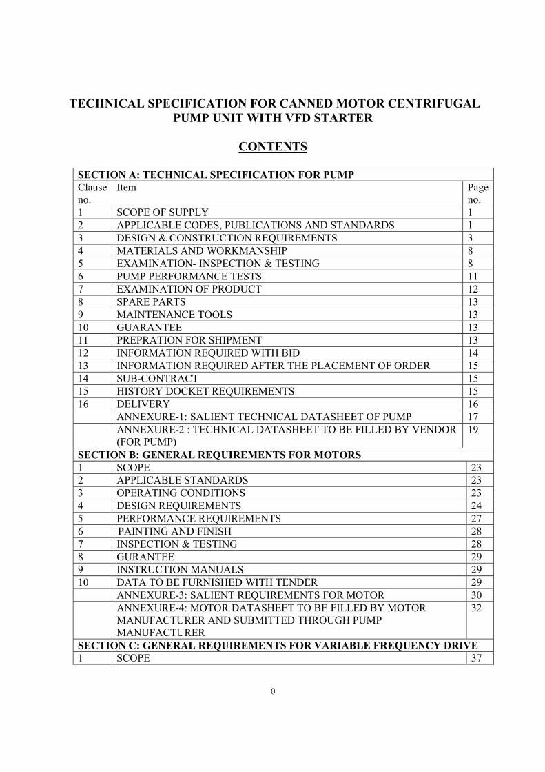
TECHNICAL SPECIFICATION FOR CANNED MOTOR CENTRIFUGAL PUMP UNIT WITH VFD STARTER
CONTENTS
SECTION A: TECHNICAL SPECIFICATION FOR PUMP Clause no.
Item Page no.
1 SCOPE OF SUPPLY 1 2 APPLICABLE CODES, PUBLICATIONS AND STANDARDS 1 3 DESIGN & CONSTRUCTION REQUIREMENTS 3 4 MATERIALS AND WORKMANSHIP 8 5 EXAMINATION- INSPECTION & TESTING 8 6 PUMP PERFORMANCE TESTS 11 7 EXAMINATION OF PRODUCT 12 8 SPARE PARTS 13 9 MAINTENANCE TOOLS 13 10 GUARANTEE 13 11 PREPRATION FOR SHIPMENT 13 12 INFORMATION REQUIRED WITH BID 14 13 INFORMATION REQUIRED AFTER THE PLACEMENT OF ORDER 15 14 SUB-CONTRACT 15 15 HISTORY DOCKET REQUIREMENTS 15 16 DELIVERY 16 ANNEXURE-1: SALIENT TECHNICAL DATASHEET OF PUMP 17 ANNEXURE-2 : TECHNICAL DATASHEET TO BE FILLED BY VENDOR
(FOR PUMP) 19
SECTION B: GENERAL REQUIREMENTS FOR MOTORS 1 SCOPE 23 2 APPLICABLE STANDARDS 23 3 OPERATING CONDITIONS 23 4 DESIGN REQUIREMENTS 24 5 PERFORMANCE REQUIREMENTS 27 6 PAINTING AND FINISH 28 7 INSPECTION & TESTING 28 8 GURANTEE 29 9 INSTRUCTION MANUALS 29 10 DATA TO BE FURNISHED WITH TENDER 29 ANNEXURE-3: SALIENT REQUIREMENTS FOR MOTOR 30 ANNEXURE-4: MOTOR DATASHEET TO BE FILLED BY MOTOR
MANUFACTURER AND SUBMITTED THROUGH PUMP MANUFACTURER
32
SECTION C: GENERAL REQUIREMENTS FOR VARIABLE FREQUENCY DRIVE 1 SCOPE 37
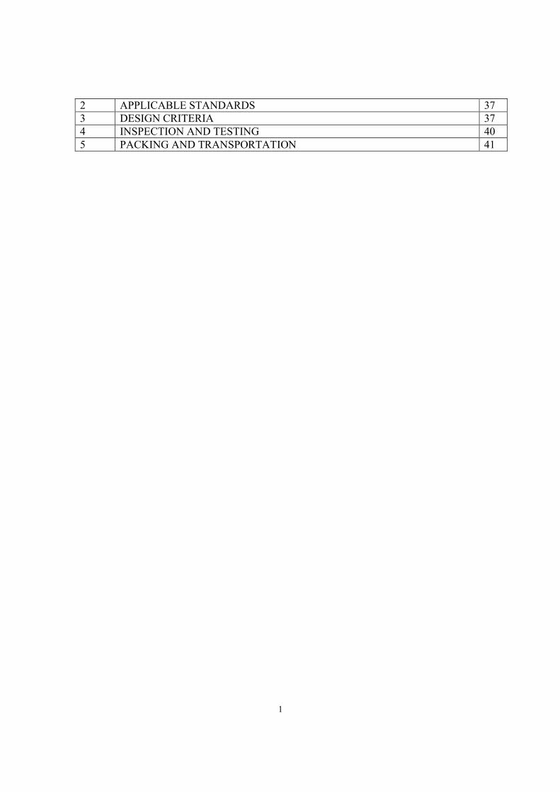
1
2 APPLICABLE STANDARDS 37 3 DESIGN CRITERIA 37 4 INSPECTION AND TESTING 40 5 PACKING AND TRANSPORTATION 41
1
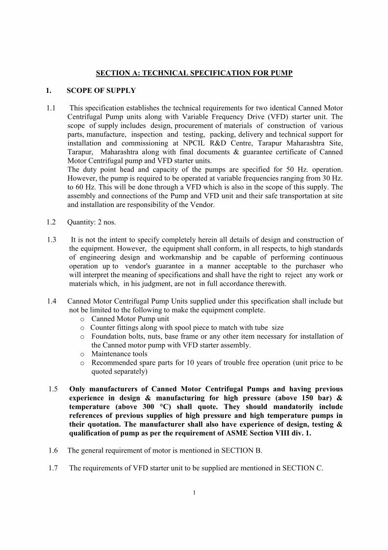
SECTION A: TECHNICAL SPECIFICATION FOR PUMP 1. SCOPE OF SUPPLY
1.1 This specification establishes the technical requirements for two identical Canned Motor
Centrifugal Pump units along with Variable Frequency Drive (VFD) starter unit. The scope of supply includes design, procurement of materials of construction of various parts, manufacture, inspection and testing, packing, delivery and technical support for installation and commissioning at NPCIL R&D Centre, Tarapur Maharashtra Site, Tarapur, Maharashtra along with final documents & guarantee certificate of Canned Motor Centrifugal pump and VFD starter units.
The duty point head and capacity of the pumps are specified for 50 Hz. operation. However, the pump is required to be operated at variable frequencies ranging from 30 Hz. to 60 Hz. This will be done through a VFD which is also in the scope of this supply. The assembly and connections of the Pump and VFD unit and their safe transportation at site and installation are responsibility of the Vendor.
1.2 Quantity: 2 nos. 1.3 It is not the intent to specify completely herein all details of design and construction of
the equipment. However, the equipment shall conform, in all respects, to high standards of engineering design and workmanship and be capable of performing continuous operation up to vendor's guarantee in a manner acceptable to the purchaser who will interpret the meaning of specifications and shall have the right to reject any work or materials which, in his judgment, are not in full accordance therewith.
1.4 Canned Motor Centrifugal Pump Units supplied under this specification shall include but
not be limited to the following to make the equipment complete. o Canned Motor Pump unit o Counter fittings along with spool piece to match with tube size o Foundation bolts, nuts, base frame or any other item necessary for installation of
the Canned motor pump with VFD starter assembly. o Maintenance tools o Recommended spare parts for 10 years of trouble free operation (unit price to be
quoted separately) 1.5 Only manufacturers of Canned Motor Centrifugal Pumps and having previous
experience in design & manufacturing for high pressure (above 150 bar) & temperature (above 300 °C) shall quote. They should mandatorily include references of previous supplies of high pressure and high temperature pumps in their quotation. The manufacturer shall also have experience of design, testing & qualification of pump as per the requirement of ASME Section VIII div. 1.
1.6 The general requirement of motor is mentioned in SECTION B. 1.7 The requirements of VFD starter unit to be supplied are mentioned in SECTION C.
2
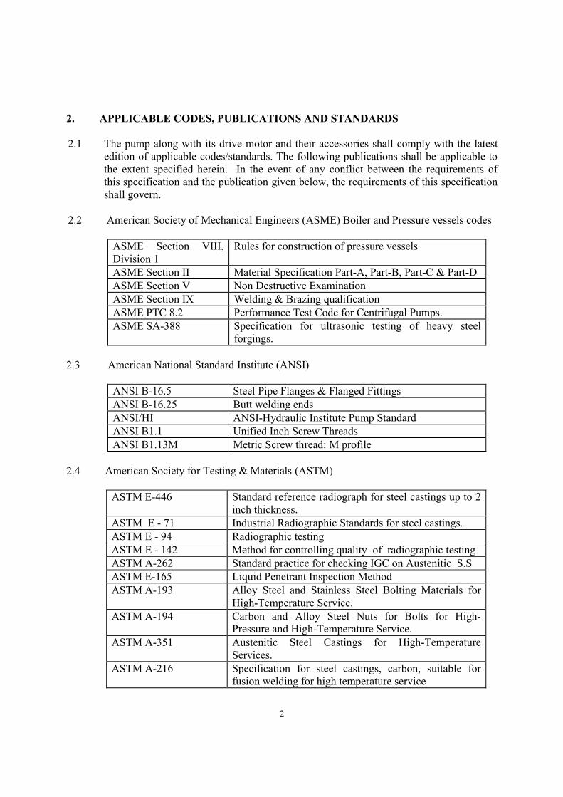
2. APPLICABLE CODES, PUBLICATIONS AND STANDARDS
2.1 The pump along with its drive motor and their accessories shall comply with the latest
edition of applicable codes/standards. The following publications shall be applicable to the extent specified herein. In the event of any conflict between the requirements of this specification and the publication given below, the requirements of this specification shall govern.
2.2 American Society of Mechanical Engineers (ASME) Boiler and Pressure vessels codes
ASME Section VIII, Division 1
Rules for construction of pressure vessels
ASME Section II Material Specification Part-A, Part-B, Part-C & Part-D ASME Section V Non Destructive Examination ASME Section IX Welding & Brazing qualification ASME PTC 8.2 Performance Test Code for Centrifugal Pumps. ASME SA-388 Specification for ultrasonic testing of heavy steel
forgings.
2.3 American National Standard Institute (ANSI)
ANSI B-16.5 Steel Pipe Flanges & Flanged Fittings ANSI B-16.25 Butt welding ends ANSI/HI ANSI-Hydraulic Institute Pump Standard ANSI B1.1 Unified Inch Screw Threads ANSI B1.13M Metric Screw thread: M profile
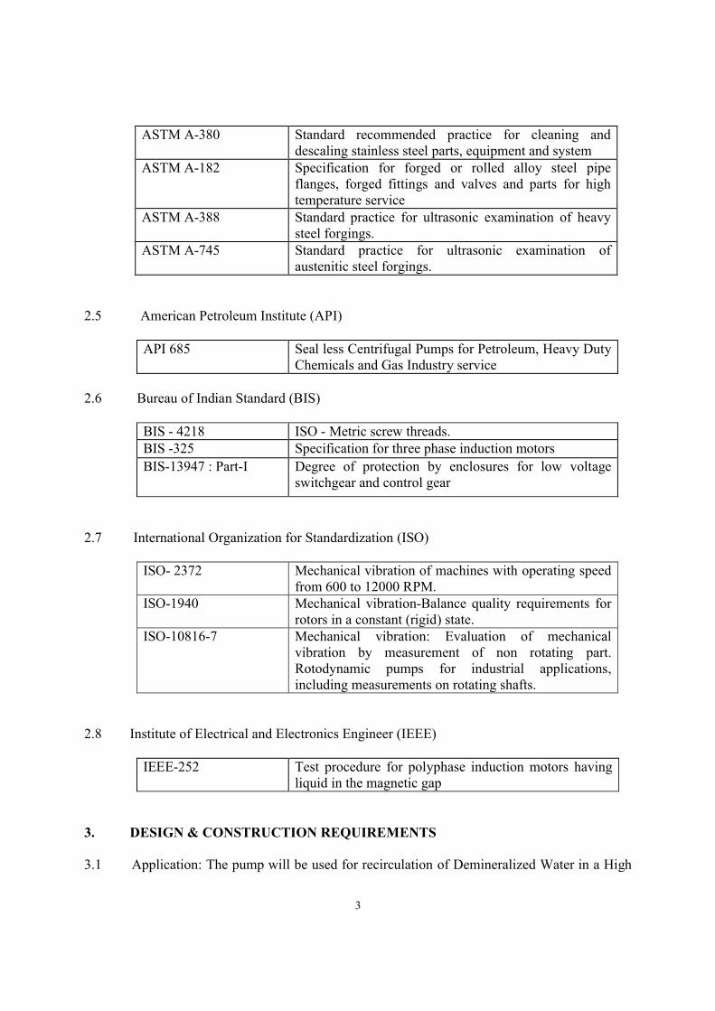
2.4 American Society for Testing & Materials (ASTM)
ASTM E-446 Standard reference radiograph for steel castings up to 2 inch thickness.
ASTM E - 71 Industrial Radiographic Standards for steel castings. ASTM E - 94 Radiographic testing ASTM E - 142 Method for controlling quality of radiographic testing ASTM A-262 Standard practice for checking IGC on Austenitic S.S ASTM E-165 Liquid Penetrant Inspection Method ASTM A-193 Alloy Steel and Stainless Steel Bolting Materials for
High-Temperature Service. ASTM A-194 Carbon and Alloy Steel Nuts for Bolts for High-
Pressure and High-Temperature Service. ASTM A-351 Austenitic Steel Castings for High-Temperature
Services. ASTM A-216 Specification for steel castings, carbon, suitable for
fusion welding for high temperature service
3
ASTM A-380 Standard recommended practice for cleaning and descaling stainless steel parts, equipment and system
ASTM A-182 Specification for forged or rolled alloy steel pipe flanges, forged fittings and valves and parts for high temperature service
ASTM A-388 Standard practice for ultrasonic examination of heavy steel forgings.
ASTM A-745 Standard practice for ultrasonic examination of austenitic steel forgings.
2.5 American Petroleum Institute (API)
API 685 Seal less Centrifugal Pumps for Petroleum, Heavy Duty Chemicals and Gas Industry service
2.6 Bureau of Indian Standard (BIS)
BIS - 4218 ISO - Metric screw threads. BIS -325 Specification for three phase induction motors
BIS-13947 : Part-I Degree of protection by enclosures for low voltage switchgear and control gear
2.7 International Organization for Standardization (ISO)
ISO- 2372 Mechanical vibration of machines with operating speed from 600 to 12000 RPM.
ISO-1940 Mechanical vibration-Balance quality requirements for rotors in a constant (rigid) state.
ISO-10816-7 Mechanical vibration: Evaluation of mechanical vibration by measurement of non rotating part. Rotodynamic pumps for industrial applications, including measurements on rotating shafts.
2.8 Institute of Electrical and Electronics Engineer (IEEE)
IEEE-252 Test procedure for polyphase induction motors having liquid in the magnetic gap
3. DESIGN & CONSTRUCTION REQUIREMENTS
3.1 Application: The pump will be used for recirculation of Demineralized Water in a High
4
pressure & High temperature Prototype Experimental Loop. The operation of loop can be continuous over several months or intermittent (as and when required) based on the experimentation needs. The various components of Experimental loop are mainly Stainless Steel 304L.
3.2 Design temperature and pressure of the pump is 360°C and 177 bar(g) respectively. Other salient technical requirements for pump are mentioned in Annexure-1.
3.3 The mechanical design of pump shall be as per ASME Section VIII, Division 1.
3.4 The pumps shall be horizontal, centrifugal with end suction and vertical upward discharge and electrically driven type. Nominal speed of Pump shall be 3500 rpm at 60Hz. frequency and 2900 rpm at 50 Hz. frequency.
3.5 The design and construction of pump-motor unit shall be suitable to take care of all aspects like balancing, misalignment, vibration, starting torque requirement etc. The design and construction shall be approved by the purchaser. Design report including stress analysis with all loading conditions & load combinations shall be submitted to purchaser for approval. The bid shall clearly indicate that they agree to comply with the requirement of supply of Design report including stress analysis with all load combination for the approval of purchaser after the placement of purchase order.
3.6 NPSH available for pump is greater than 5 m for duty point condition.
3.7 The drawings giving overall dimensions of the complete pump-motor assembly with foundation and base plate details must be submitted by the bidder for pump-Motor unit along with the quotation/bid to facilitate the technical evaluation.
3.8 The Pump-Motor unit will be located in an area where ambient temperature will be
between 10 to 50 oC. The units shall be suitable for the above service conditions. 3.9 The Pump-Motor unit shall be designed with regard to ease of maintenance, inspection
and repair. The design shall be such that any maintenance required can be performed by persons with the skills that are normally available in power plants. The design of the pump and motor shall be such that maintenance is not normally required more frequently than once in every three years and preferably not more frequently than once in every five years.
3.10 All pump components, with the exception of bearings and parts specifically designed for
easy replacement, shall be suitable for a minimum of 20 years continuous duty operation.
3.11 The pump drive motor must be suitable for operation at 60 Hz. frequency and shall
follow the requirements given in the specification for motors, which are enclosed herein (Section-B). Supply voltage will be 3 phase 415 V.
5
3.12 Instruments The pump-motor unit shall be provided with at least but not limited to following instruments for safe and satisfactory operation of the pump-motor unit
A) Bearing wear monitor indicator is to be provided to monitor the bearing condition. This shall give signal for replacement of bearing before excessive damage.
B)Thermostat on stator winding for protection against overheating. 3.13 External Nozzles forces & moments The pump shall withstand and be capable of satisfactory operation when subjected to the
forces and moments mentioned in API 685 corresponding to suction and discharge size of the pump volute. To minimize the misalignment of the pump and the driver shaft due to piping load effects, the pump and its base plate shall be constructed with sufficient structural stiffness to limit the displacement of the pump shaft at the driven end of the shaft. The pump supports shall be capable of accommodating the external loads without sustaining any significant displacements that would cause unacceptable misalignment of rotating parts.
3.14 Pump operation 3.14.1 The rating of the motor shall be suitable to drive the pump for the entire range of flow
up to 120% of rated flow while operating with high pressure and temperature DM water specific gravity 1.0. It should be designed to operate for frequency up to 60 Hz.
3.14.2 Performance The pump should have a continuously drooping characteristic such that the head
decreases with increasing capacity. It shall be stable when operating alone or in parallel with other similar pumps. The rise of total head from rated flow to shut off head at rated speed shall be as high as possible. The upper limit shall be specified by manufacturer and shall be compatible with design pressure.
3.14.3 The Operating conditions and Design conditions for pump-motor unit is given in Annexure-1.
3.15 Detailed requirement 3.15.1 The pump-motor unit shall be suitable for indoor installation/operation. 3.15.2 The impeller shall be securely keyed to the shaft. Means shall be provided to prevent
loosening of impeller during operation including rotation in reverse direction. 3.15.3 The impeller shall be of non-overloading type. The impeller shall be fully
enclosed/semi enclosed type and constructed as single piece casting. Fabricated impeller is not acceptable.
3.15.4 The pump casing shall be of robust construction. All liquid passages in the casing shall
be finished smooth.
3.15.5 Casing and its nozzles shall withstand usual moments and thrust. The maximum value of moments and forces in all directions that the casing can withstand shall be indicated.
6
However, the values shall not be less than that mentioned in API 685 Clause corresponding to suction and discharge nozzle size.
3.15.6 Suitable base plate shall be provided for pump-motor unit. Suitable holes shall be
provided for grouting and they shall be so located that the base can be grouted in place without disturbing the pump-motor unit.
3.15.7 The size of pipes where pump is to be connected is provided with 4” NB 2500 lbs
flanged fitting on both suction and discharge side. The vendor shall provide suitable spool piece to connect the Pump with the pipe.
3.15.8 The bearings shall be lubricated with pumped liquid (Water) itself i.e. no external lubrication shall be required. It shall permit easy removal and replacement. Provision for continuous venting shall be made to avoid dry running of bearing. The rated life of the bearings shall be guaranteed to be not less than 30,000 hours of operation. The vendor shall also furnish the relevant details regarding the bearings used in the pump-motor and indicate the expected life.
3.15.9 Mating components of same materials of construction shall have adequate
hardness difference and the replaceable component shall preferably have lower hardness than the non replaceable component.
3.15.10 The shaft shall be finished smooth and surface finish shall be indicated. 3.15.11 All the surfaces coming in contact with the liquid pumped shall be made smooth. 3.15.12 All welds and weld repairs subjected to hydrostatic pressure shall be made in
accordance with ASME section- VIII, Divison 1. 3.15.13 Examination of the cast pressure retaining materials shall be carried out as per
the requirements of ASME Section VIII, Division 1. However, additional examination as mentioned in Clause no. 5 shall also be carried out.
3.15.14 Shaft Design shall be such that the fatigue strength of the shaft is not reduced by notches and
surface finish shall be 3.2 micron Ra or better. 3.15.15 Balance and vibration The first critical speed of the complete rotating assembly shall be not less than 130%
of rated speed. The unit shall be mechanically and hydraulically balanced so that the maximum value of vibration of the pump-motor unit, while the unit is operating at rated conditions, shall be well within zone B of the applicable class of machine as per ISO 10816-7. Pressure pulsation or vibrations in the pumped fluid shall not cause excessive or undue vibrations of the connected piping and equipment. Dynamic balancing of the rotating assembly shall be carried out as per approved procedure. The rotating part pump-motor unit shall confirm to balance quality grade
7
G2.5 as per ISO 1940. The procedure shall conform to ISO-1940, "Balance quality of rotating rigid bodies."
3.15.16 Pump-Motor unit Base The pump-motor unit base shall be of sturdy construction to withstand the weight
of the complete pump-motor unit, vibration loads and normal piping loads. The final foundation details shall be worked out by the vendor in consultation with the purchaser.
3.15.17 Draining and venting Vent and drain connections with flanged valves, shall be provided and arranged so
that all spaces normally filled with the pumped liquid can be completely drained before the pump is opened for maintenance and similarly while filling, no air pockets are left.
3.15.18 Auxiliary connections and piping All nozzles for auxiliary connections e.g. drain & vent shall be welded to the pump
body, the details of which shall be subject to purchaser's approval. All tapping connections shall be brought out to accessible locations and shall be terminated with S.S. 304L gate valve. The free end of each valve shall have NPT threads and closed with a threaded S.S. plug.
3.15.19 Threaded fasteners Threads on screws, studs, bolts and nuts shall conform to metric system. All fasteners
shall be provided with corrosion resistant positive locking devices, to prevent loosening. Frictional locking device shall not be used. Threads on all screws, studs, bolts and nuts shall confirm to ANSI B1.1 or ANSI B 1.13M standard.
3.15.20 Surface condition and finish All fluid passages shall have a good surface finish. The internal and external surface of
cast pressure bearing components and welds shall have a surface finish of 10 microns RMS or better.
The local surface discontinuities which results because of defects which are acceptable
under Inspection/testing clause (Clause no. 5) are acceptable notwithstanding the above surface finish requirements.
3.15.21 Cleaning Cleaning of parts shall be carried out in accordance with ASTM A380. All inside
surfaces shall be degreased and then flushed with clean water. The de-greasing agent and water used for cleaning shall not contain more than 25 ppm sulphur and halogen. Surfaces shall be visibly clean and there shall be no discoloration or evidence of oil, grease, dirt etc.
3.15.22 Handling Pump-motor unit shall be provided with suitable lifting lugs or eye bolts for handling. 3.15.23 Identification
8
The pump-motor unit shall be provided with a corrosion resistant identification tag. This tag shall be attached to the pump by corrosion resistant tagging wires.
4. MATERIALS AND WORKMANSHIP 4.1 The material of construction of different parts of pumps shall be as per following
Casing ASTM A-182 Grade F 304L (Preferred)
or /ASTM A-351 Grade CF3 (SS 304L)
Impeller ASTM A-351 Grade CF3 (SS 304L) Shaft ASTM A-182 Grade F 304L Stator and Rotor CAN ASTM B 575 (N10276) Hastelloy C276 Auxiliary piping Stainless steel compatible with pump MOC Counter fitting along with spool piece Stainless steel 316L Base Plate IS 2062
4.2 The cobalt content in all wetted parts (In contact with circulating Fluid) shall be less than 0.1 % by weight.
4.3 Materials and standard parts which are not specifically described herein and which are necessary for the fulfillment of this specification shall be of good quality and in accordance with the best practice, adequate to ensure satisfactory operation, service life and ease of maintenance in accordance with the provision of this specification.
4.4 Other material of construction of other wetted parts shall be Stainless Steel or other corrosion resistant material for high pressure and temperature service.
4.5 Bolting materials shall not gall.
4.6 The materials of construction as indicated in this specification are the minimum acceptable. The vendor may offer equivalent or better materials provided each material is approved by the purchaser.
4.7 Materials shall be tested/inspected in accordance with Inspection & testing mentioned in this specification and the relevant ASTM material specification and shall meet all the requirements stated therein.
4.8 Heat treatment of castings, forgings and other parts shall be carried out as per requirements of materials specifications using calibrated furnace.
5. EXAMINATION- INSPECTION & TESTING
5.1 General The vendor shall be responsible for and shall provide and perform the examination, inspection and testing in accordance with the requirements of ASME Section VIII div. 1,
9
ASME Section V and test mentioned in relevant ASTM standard which are specified herein. All products shall be carefully examined during manufacture and after completion to determine their conformance with this specification with respect to material, workmanship, finishing, marking and dimensions and to assess their conformance with other requirements stated or reasonably implied and not covered by specific test. The vendor shall submit a detailed QAP for the approval of the purchaser before commencement of manufacture. Examination, inspection and testing shall be conducted in a manner satisfactory to and shall be subject to approval by purchaser. Inspection and test reports shall be submitted by the contractor to the purchaser for approval. The purchaser or his authorized representative shall have access to the contractor's premises at all reasonable times to the extent necessary to assess compliance with the provisions of this specification. The purchaser shall also have the right to conduct at his own expense any additional inspection or testing.
All the inspection/testing specified herein unless otherwise specified shall be witnessed by the purchaser/his authorized representative. The calibration certificate shall be provided before the inspection visits. Purchaser/ Inspector may witness the calibration of important instruments
5.2 Inspection or test failure In the event of the equipment or any part thereof failing to meet the examination or test requirements specified herein, the contractor shall furnish the detailed mapping of the defects/ failures and all relevant details to the purchaser. The contractor shall obtain written permission from purchaser before repair and subsequent use of such equipment or part. If the repairs, including re-design, are likely to affect the result of tests or work previously completed, appropriate re-examination and re-testing shall be conducted and resubmitted to Purchaser for approval. Permission from the purchaser is required to perform weld repairs on castings. A report shall be made on casting repairs describing the extent and location of repairs to each casting.
5.3 Material Examination All materials designated to be in conformance with an ASTM standard shall be tested as required by such standard and ASME Section VIII, Division 1. For pressure retaining parts, NABL accredited laboratory calibrated instrument shall be used for the material testing and the same shall be witnessed by purchaser or his authorized representative. For other materials, Proof in the form of certified test report or mill certificates with proper correlation that the required tests have been carried out at the source will be acceptable but if these are not available, these tests will be performed by

10
vendor. All casting materials (which are in contact with process fluid) shall be checked for Inter Granular Corrosion test as per ASTM A-262 practice A/B. For IGCT carried out as per ASTM-A-262-practice B, the corrosion rate shall not exceed 50 mpy.
5.4 Visual Examination It will be confirmed visually that all castings, forging and/or other raw materials are free of flaws, cracks, blow, holes or other defects. Visual examination shall be performed for external appearance of pump motor unit and internals shall be checked after dismantling.
5.5 Liquid penetrant examination 5.5.1 Liquid penetrant examination shall be performed as per ASME Section V. Procedure
shall be subject to Purchaser's approval. Following parts shall be subjected to Liquid penetration examination.
a) All accessible surfaces of pressure retaining parts b) First and last passes of all welds c) Impeller d) Shaft e) Weld repair areas, if any f) Machined parts in contact with pumped fluid g) Weld edge preparations h) Surface prior to and after hard facing i) Bolts j) Stator spacing rings, rotor bars, short circuit rings, retaining rings and brazed
joints in the motor.
Acceptance standards for shaft, shaft sleeve, castings, forgings, hard facing surfaces, for weldment, for bolts and for weld edge preparation shall be as per requirements of ASME Section VIII div. 1.
5.6 Radiographic examination 5.6.1 Radiographic examination in accordance with the approved procedure shall be performed
on the following components : i) All castings components which are pressure retaining. ii) Longitudinal weld of stator and rotor cans iii) All butt welds and weld repairs (if any), subjected to hydrostatic pressure.
Radiographic technique shall be as per relevant ASTM standard or ASME Section V standard.
5.7 Ultrasonic Examination
Ultrasonic examination in accordance with the standard procedure shall be performed on i) Shaft of pump-motor unit. ii) Pressure retaining components (which are subject to hydrostatic pressure) which are forged. iii) Body of the Motor. The examination shall be performed after heat treatment. It shall be examined in
11
accordance with ASTM A-388 (specification for ultrasonic examination of heavy forgings).
5.8 Ferrite control
Delta ferrite determination shall be carried out on casing, impeller, other pressure retaining Stainless Steel parts and also on stainless steel welding materials. Minimum delta ferrite shall be 5%.
5.9 Dimensional Examination Dimensional examination shall be carried out on all dimensions indicated on various approved drawings. The measured dimensions shall be within specified tolerances.
5.10 Hydrostatic test All pressure retaining components shall be subjected to hydrostatic pressure of at least 285 bar (g) (Which is near to1.3 times the design pressure multiplied with allowable stress ratio at room temperature to the design temperature). The test shall be conducted in accordance with ASME Section VIII division 1, latest edition. Hydrostatic test pressure shall be kept constant for a period of 10 minutes. No leakage or permanent distortion shall be allowed. Any permanent distortion or seepage of water shall be the cause of rejection of the units. Hydrostatic test shall be carried out using clear water.
5.11 Helium leak test After hydro test, helium leak test shall be performed on complete pump-motor assembly, at a differential pressure of 1.03 kg/cm2 with minimum 50% helium. Helium leak test of pressure retaining parts is to be carried out by vacuum method only. This will be followed by Pressure/Sniffer probe technique to locate the leaks, if leakage rate exceed the acceptance limits during Vacuum method. Prior to the test, the components shall be thoroughly dried at 150 °C for 2 hrs. while being purged with a flow of dry air. The pump-motor unit shall be enclosed in vinyl sheet. Vacuum will be pulled inside the pump and helium shall be injected in the vinyl sheet. The maximum leak rate of helium to the pump inside shall not exceed 10-6 std. cc/sec for weld joint. For Gasket/O-ring joints maximum leak rate preferably shall not exceed 10-5 std. cc/sec, However, leak rate more than 10-4 std. cc/sec is not acceptable for Gasket/O-ring.
6. PUMP PERFORMANCE TESTS 6.1 General
The pump-motor unit manufactured shall be subjected to the general performance test and rated performance test as specified below. The pump running tests shall be performed at different voltages and frequencies as mentioned below. The pump-motor unit shall not be modified for testing. The performance tests and acceptance criteria shall be made in accordance with the ANSI/HI pump standard or equivalent. The performance tests shall be witnessed by the purchaser/ his authorized representative.
12
The performance tests shall be carried out using clear water at near room temperature Since the pump required to be operated at different frequencies at our premises, the testing will be carried out at four electrical frequencies viz., 30, 40 50 and 60 Hz. set by the VFD. The performance requirements as specified in the following sections of this specification are for tests performed at rated voltage of 415V and 50 Hz. frequency unless stated otherwise
6.2 Pump performance test Measurement shall be made to determine the characteristics of the units over the entire range of flow from zero to maximum permissible flow (which shall not be less than 120% of duty point flow). A sufficient number of points shall be obtained on the characteristic curve to enable an accurate plot to be made. The characteristics to be determined and submitted as test curves are: Developed head, Required NPSH, Pump power, Shaft torque and Efficiency vs. flow. Water temperature and pump RPM shall also be noted and submitted. The test results shall be extrapolated for actual condition. Similar test has to be carried out for different frequencies viz., 30, 40 and 60 Hz..
6.3 Strip down test The pump-motor unit shall be operated at rated voltage, frequency (50 Hz.) and flow for 24 hours. The measurements shall include voltage, starting current and running current, frequency, power input, winding temperature, rpm, capacity, head, water temperature, vibration, noise, gasket leakage if any, overall efficiency of the unit etc. During this test, various measurements taken during general performance test as stated in above clause shall be made and recorded once in 2 hours. The observed values must match with required values. After the rated performance test, pump assembly shall be disassembled and after checking all components for any failure/ damage the pump shall be assembled back. In case of any part or component requires replacement/modification, re-testing (for 8.0 hrs at rated conditions) and re-examination shall be carried out. After reassembly, pump shall be checked for satisfactory operation for 10-15 minutes.
6.4 Vibration test The vibration test shall be carried out as per relevant industrial standard and shall confirm to Zone B as per the ISO-10816-7 standard.
6.5 Dynamic Balance test Dynamic balance test of pump-motor assembly is to be carried out as per ISO-1940. The rotating parts of pump-motor unit shall confirm to balance quality grade G2.5.
6.6 Impeller loss coefficient test This is not a standard test and will involve passing a metered flow rate (5-20 m3/hr) of water from suction to discharge end of the pump. During this test the pump will not be powered and the impeller will be free to rotate. The pressure drop from suction to
13
discharge end shall be measured. Measurement of flow and pressure drop will be reported for 10 points in the range of flow specified.
7. EXAMINATION OF PRODUCT The pump and motor unit shall be carefully examined during manufacture and after completion to determine their conformance with this specification with respect to materials and their testing and workmanship, finish, marking and dimensions and to assess their conformance with other requirements stated or reasonably implied and not covered by specific tests.
8. SPARE PARTS The supplier shall recommend a list of spares along with unit price that are required for 10 years operation to be stocked for maintenance purposes. The purchaser has right to purchase/not to purchase any or all spares and unit price of spare shall remain same.
9. MAINTENANCE TOOLS The bidder shall supply one set of maintenance tools required for installation and regular maintenance of pump-motor unit at no extra cost.
10. GUARANTEE The pump-motor-starter unit shall be guaranteed for a period of 18 months after installation or 36 months from the date of shipment whichever is earlier, against any malfunctioning, defects in design, materials or workmanship. If within the expiry of this guarantee period the equipment fails to operate satisfactorily at its rated conditions or the subject goods or any part thereof are found defective in design, workmanship or materials, the supplier shall be responsible to arrange repairs/ replacement (at Purchaser's premises) at his own cost. The guarantee period for the replaced parts or repair work shall be the same as above.
11. PREPRATION FOR SHIPMENT The units shall be prepared for shipment and prolonged storage as stated below: The interior of the pump-motor unit shall be thoroughly cleaned and dried. All external, internal, machined and unfinished surfaces susceptible to corrosion shall be protected against corrosion with a liberal coating of an approved easily removable rust preventive compound. The compound shall be such that it will not chemically react with the material and shall be stable up to an ambient temperature of 50 °C. It shall remain on the surfaces at temperatures encountered during the long periods of shipment and storage. It shall not be washable with water but shall be easily and thoroughly removable with a non-corrosive solvent. All machined surfaces shall be protected against mechanical damage. Paints or chemicals used for marking, preserving or testing shall be halogen and sulfur free. All openings shall be adequately sealed to prevent ingress of corrosive water vapor. Suitable desiccant or rust-inhibitor shall be kept inside, if necessary, prior to sealing. Flanged openings shall be closed with plywood blank flange held in place with bolts and
14
sealed with a blank gasket of natural rubber or equivalent. Threaded openings shall be closed with suitable threaded plugs or caps (for internally or externally threaded openings respectively) using a good quality thread tape. No thread sealant shall be used. All components shall be tropical packed, suitably boxed, crated and protected from damage and moisture in transit to site. The crates shall be suitably lined with water proof material to prevent ingress of moisture. Equipment shall be prepared for a period in transit exceeding two weeks. The construction and lining of the boxes shall provide protection for its components. The packaging shall provide adequate cushioning, blocking and bracing to protect against shocks and prevent internal movement of the unit. Adequate skidding, hoisting and tie down provisions shall be provided to facilitate easy handling and safe movement. Delivery of the pump-motor unit or any part must not take place until the purchaser has been notified and a written shipping release of the material is obtained.
12. INFORMATION REQUIRED WITH BID FOR PUMP Two copies of quotation complete in every respect should be forwarded along with detailed catalogues, specifications, data sheets etc. Quotations not giving complete information, as asked below, will be liable to rejection. Following information shall be provided by the bidders along with the quotation.
12.1 Sectional drawings of the pump-motor unit showing overall dimensions, materials of construction and details of suction/ discharge connections, motor, support details etc.
12.2 Base plate and foundation details 12.3 Required NPSH of the pumps. 12.4 Performance curves: Delivered head, NPSHR, Pump power, Shaft torque, Efficiency Vs.
flow at the rated speed (RPM).
12.5 Guaranteed Head and capacity of the unit. 12.6 Rated maximum operating temperature
12.7 Completed Pump and motor data sheet (Annexure-2 of Section A and Annexure-4 of
Section B). Offer without these filled data sheets shall not be considered for the evaluation.
15
12.8 A recommended spare parts list complete with unit prices and recommended quantities of each spare part required for at least ten years of trouble free service.
12.9 List of previous supply order where similar size, type & quality of high pressure &
temperature pumps have been supplied (indicate the P.O. number & total price). 12.10 Guaranteed life of the pump-motor unit. 12.11 Design, test pressure & Overall efficiency of the pump-motor unit. 12.12 Complete list of deviations from this specification, if any. 12.13 QAP including details of stage-wise inspection to be followed during manufacture.
13. INFORMATION REQUIRED AFTER THE PLACEMENT OF ORDER 13.1 Detailed shop drawings of the pump- motor unit indicating material of construction and
dimensions, shall be submitted for purchaser's approval.
13.2 Design report including analysis with all load combination shall be submitted for purchaser’s approval prior to commencement of fabrication/manufacture.
13.3 Inertia of the Pump-Motor Unit
13.4 Part list for the pump ordered.
13.5 Detailed Quality Assurance Plan for purchaser’s approval.
13.6 Detailed inspection/test procedures as per the specification shall be submitted to the purchaser for approval prior to start of manufacture of pump-motor units.
13.7 Material test certificates, tests and inspection reports shall be submitted.
13.8 Instruction manual containing installation, operation and maintenance instructions, part
list and dimensional drawings shall be submitted.
14. SUB-CONTRACT The vendor shall not sub-contract any or all of the work without the written consent from the purchaser. The vendor shall be responsible to the purchaser for all works under this contract including the works of the sub-contractors, as allowed by the purchaser. Sub-contracting should not affect the delivery schedule or product quality under any circumstances.
15. HISTORY DOCKET REQUIREMENTS Two copies of History docket shall be submitted along with CD containing Scanned copy of
the same. The docket shall contain following quality assurance records & documents. Purchase order with technical specification
16
All Official correspondence All Design and pump performance documents Approved and as built drawings Approved QAP Certified material test report Heat treatment records All NDT documents including approved procedures Hydrostatic test reports Performance test reports Guarantee certificate Instruction and maintenance manual Any other relevant documents
16. DELIVERY
The delivery of all the pump-motor units shall be within Eight (08) months after placement of purchase order.
17
ANNEXURE-1: SALIENT TECHNICAL DATASHEET OF PUMP
General
Type Centrifugal Canned motor type ( Leak proof centrifugal)
Configuration Single Volute, Horizontal end suction, vertical discharge
Quantity 2 nos.
Material of construction of wetted part
Stainless Steel 304L with relevant ASTM standard (as mentioned in Clause 4).
Cobalt content in all wetted parts (In contact with circulating Fluid) shall be less than 0.1 % by weight.
Applicable Code Design, fabrication & testing: ASME Section VIII,
Division 1. Performance test: ANSI/HI or equivalent standard
Suction & Discharge line size (Matching connection with pump is in scope of Vendor)
4” NB 2500 lbs flanged connection
Location Indoor Pump prime mover Induction motor as per specification mentioned in
Section B Pump starter To be provided with Variable Frequency Drive (VFD)
control. Design and Operating Conditions Operation Continuous
Fluid Handled Demineralized Water
Design Temperature 360 oC
Design Pressure 177 bar(g)
Operating temperature Max.: 340 °C Normal: 280°C - 325 °C Min.:25 °C
Operating suction pressure Max. : 157 bar(g) Normal: 145 bar (g) - 148 bar (g) Min.: 50 bar(g)
Duty point Capacity at 50 Hz. frequency
28.8 m3/hr
Duty point at 50 Hz. frequency 30 mWC
NPSH available at duty point condition > 5 mWC
Performance Head decreases with increasing capacity for entire range of flow.
External nozzles forces and moments As mentioned in Clause 3.14
18
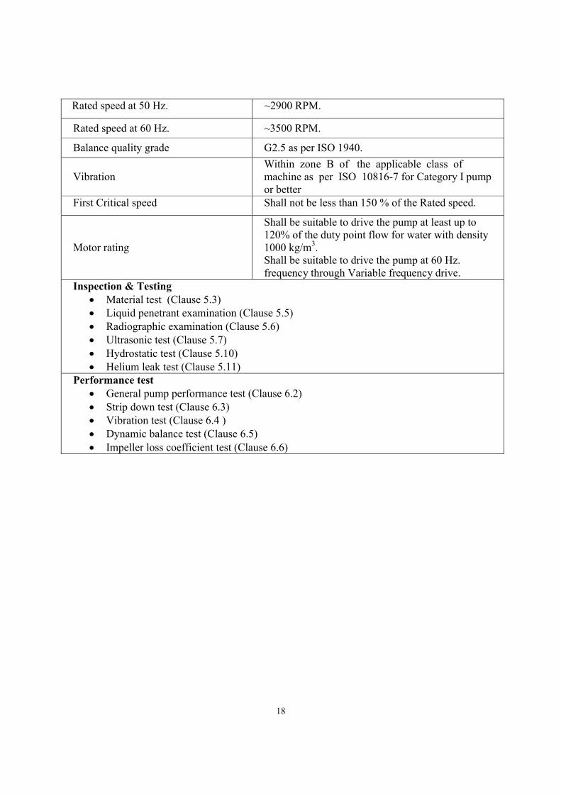
Rated speed at 50 Hz. ~2900 RPM.
Rated speed at 60 Hz. ~3500 RPM.
Balance quality grade G2.5 as per ISO 1940.
Vibration Within zone B of the applicable class of machine as per ISO 10816-7 for Category I pump or better
First Critical speed Shall not be less than 150 % of the Rated speed.
Motor rating
Shall be suitable to drive the pump at least up to 120% of the duty point flow for water with density 1000 kg/m3. Shall be suitable to drive the pump at 60 Hz. frequency through Variable frequency drive.
Inspection & Testing Material test (Clause 5.3) Liquid penetrant examination (Clause 5.5) Radiographic examination (Clause 5.6) Ultrasonic test (Clause 5.7) Hydrostatic test (Clause 5.10) Helium leak test (Clause 5.11)
Performance test General pump performance test (Clause 6.2) Strip down test (Clause 6.3) Vibration test (Clause 6.4 ) Dynamic balance test (Clause 6.5) Impeller loss coefficient test (Clause 6.6)
19
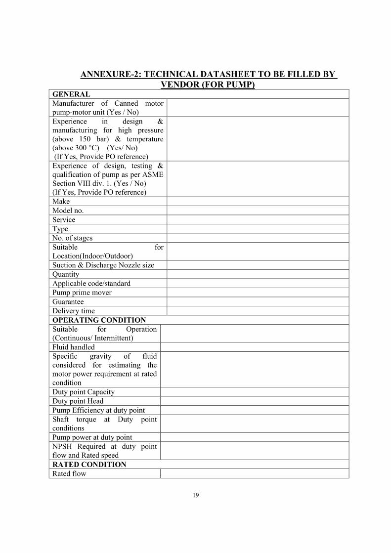
ANNEXURE-2: TECHNICAL DATASHEET TO BE FILLED BY VENDOR (FOR PUMP)
GENERAL Manufacturer of Canned motor pump-motor unit (Yes / No)
Experience in design & manufacturing for high pressure (above 150 bar) & temperature (above 300 °C) (Yes/ No) (If Yes, Provide PO reference)
Experience of design, testing & qualification of pump as per ASME Section VIII div. 1. (Yes / No) (If Yes, Provide PO reference)
Make Model no. Service Type No. of stages Suitable for Location(Indoor/Outdoor)
Suction & Discharge Nozzle size Quantity Applicable code/standard Pump prime mover Guarantee Delivery time OPERATING CONDITION Suitable for Operation (Continuous/ Intermittent)
Fluid handled Specific gravity of fluid considered for estimating the motor power requirement at rated condition
Duty point Capacity Duty point Head Pump Efficiency at duty point Shaft torque at Duty point conditions
Pump power at duty point NPSH Required at duty point flow and Rated speed
RATED CONDITION Rated flow
20
Rated head Rated Efficiency (BEP Efficiency)
Rated shaft torque Pump power at rated condition Max. Allowable operating temperature at suction.
Rated speed (RPM) Synchronous speed (RPM) DESIGN PARAMETERS Performance (Characteristics Curve to be attached for 30, 40, 50 and 60 Hz. operation)
Maximum permissible flow for continuous pump operation (run-out flow) at 30, 40, 50 and 60 Hz.
Pump power at run-out condition for 30, 40, 50 and 60 Hz.
Max. Pump rating Shut off head for 30, 40, 50 and 60 Hz.
Max. permissible duration for pump operation at shut off head
Minimum permissible flow for continuous pump operation
First critical speed (RPM) Specific speed Suction Specific speed Impeller type Nos. of Impeller stages Design pressure Design temperature Casting quality factor considered for pump casing design
Hydrostatic test pressure Rotating Mass moment of inertia of Pump-Motor unit
Overall size of Pump- motor unit Minimum required Foundation size for installing one pump-motor assembly
External nozzles forces and moments considered
Impeller dia. Impeller radial clearance

21
Max. diameter of impeller, the casing can accommodate and rated condition for the same impeller
Shaft dia. Weight of total pump-motor unit External (Jacket) cooling water requirement, if any (Category of Water/Flow/Inlet pressure/ Pressure drop/ Inlet temperature/ Heat to be removed etc.)
Bearing (Type and Lubrication) Direction of Rotation Balance Quality Grade of the rotors.
Vibration of the unit while operation
MATERIALS OF CONSTRUCTION ( With relevant ASTM standard, as applicable) Casing Impeller Shaft Stator and Rotor CAN Auxillary piping Counter fitting Spool piece for matching the tube size with Suction & discharge nozzle size of pump
Base Plate
Bearing Bearing sleeve Gasket O' Ring Stator body All bolts & nuts Other material of construction of wetted part
Cobalt content in all wetted parts (In contact with circulating Fluid) shall be less than 0.1 % by weight. (Yes/ No)
INSPECTION AND TESTING (Mention the different components & relevant standard for which the tests are to be carried out). Material test Liquid penetrant Examination Radiographic examination
22
Ultrasonic examination Hydrostatic test Helium leak test Confirm that all the above tests are to be carried out as per Clause no. 5 (Yes / No)
Agree for Witnessing of inspection/ testing by the purchaser (Yes / No)
PERFORMANCE TEST (Mention the relevant standard) General pump performance test Strip down test Vibration test on all pumps Dynamic balance test on all pumps
Confirm that all the above tests are to be carried out as per Clause no. 6 (Yes / No)
Agree for Witnessing of inspection/ testing by the purchaser (Yes / No)
MOTOR ( Please also fill Annexure-4 for of motor) Type Make Max. Rating Motor efficiency at duty point condition (at 50 Hz.)
OTHER Recommended spares (Please attach the list along with unit price) Regular maintenance tool to be provided with Pump-Motor unit
(Please attach the list)
Whether pump offered meet all the requirement mentioned in this specification (Yes/ No)
If no then attach the deviation list
END OF SECTION A
23
SECTION B: GENERAL REQUIREMENTS FOR MOTORS 1. SCOPE This specification covers the general requirements for design, manufacture, inspection, testing and supply of squirrel cage induction motors having a rated capacity to suit Pump as specified in the section A and requirement specified in this section B. This specification is meant only for the guidance to the supplier and it is not the intent to cover all aspects of design and manufacture. 2. APPLICABLE STANDARDS The motors shall conform to the latest editions of the following standards unless specified otherwise in this specification. 2.1 Bureau of Indian Standard (BIS)
BIS-325 Specification for Three-Phase Induction Motors BIS-12615 Energy efficient induction motors- Three phase squirrel
cage BIS-12075 Mechanical vibration of rotating electrical machines with
shaft heights 56 mm and higher measurement, evaluation and limits of vibration severity
BIS-15881 Three phase cage induction motor specifically designed for IGBT converter supply specification
In case of conflicts, requirement specified in this specification shall govern. 3. OPERATING CONDITIONS 3.1 Motors shall be suitable for continuous operation under the following conditions
Ambient temperature at the location of motor
10 to 50 °C
Site altitude Less than 1000 metres Relative Humidity 90% at 40 °C Rated voltage and its variation 415 V ± 5% at 50 Hz. Further, the motor
should be designed to also operate up to input frequency of 60 Hz.
Rated frequency and its variation 60 Hz ± 3 % Number of Phases 3 Sustained Combined variation of frequency and voltage (arithmetic addition)
10 %
Unbalance in supply voltage 3 % Permissible harmonics in the supply voltage Less than 5 % Method of power supply system grounding Effectively grounded system Temperature rise of motor winding under normal operating conditions of voltage and
Less than that mentioned for Class B
24
frequency (By winding resistance method) Temperature rise of motor winding under extreme conditions of voltage and frequency (By winding resistance method)
Less than that mentioned for Class F
4. DESIGN REQUIREMENTS 4.1 General 4.1.1 The salient technical requirement of Motor is mentioned in Annexure-3.
4.1.2 Motors shall be designed, manufactured and equipped with accessories in accordance
with this specification and the applicable standards. Materials and components not specifically stated in this specification and which are necessary for meeting the requirements of this specification shall be included in the scope of supply.
4.1.3 The design and workmanship shall be in accordance with the best engineering practices to ensure satisfactory performance and service life as specified herein.
4.1.4 The intent of this specification is that the contractor supplying the equipment shall provide motors which shall be suitable for properly starting and operating the equipments under operating and environmental conditions as specified in the specification.
4.1.5 The motors shall be preferably of the squirrel cage induction type and shall be manufactured, tested and shall perform in accordance with the latest revision of BIS-325 or equivalent.
4.1.6 Design and manufacture of the motors shall be coordinated with the requirements of the driven equipment. The motor manufacturer shall cooperate fully with the purchaser and the manufacturer of the driven equipment by furnishing the following information necessary for proper assembly and operation of the unit as a whole. i) A fully dimensioned outline drawing of the motor and its terminal box arrangement. ii) The relevant motor characteristics viz. speed/torque and speed/current etc. iii) The maximum permissible temperature under stalled rotor conditions for cold and hot motor, when started on full rated voltage. iv) Information required like rated speed, number of starts/restarts, operating duty, load on bearings, mounting, instrumentation, Weight etc.
4.1.7 The vendor shall make available to the motor manufacturer a copy of this specification and shall be responsible to the purchaser for coordinating with the motor manufacturer for the supply of the required motor and accessories and for the satisfactory operation of the complete unit.
4.1.8 Motor shall have the kW rating based on continuously driving the connected equipment under all specified operating conditions. The vendor may indicate the various de-rating factors considered, if any for the motors.
25
4.1.9 Minimum efficiency of motors shall be as per relevant Indian Standard (IS).
4.1.10 Motor shall be powered through a variable speed drive (as described in section C of this specification) and shall be suitably designed to take in to account harmonics and voltage surges generated by such drives. Suitability of the motor for operation with such drives shall be confirmed.
4.2 Enclosures Motors shall be provided with explosion proof enclosure providing degree of protection not less than IP 66.
4.3 Rotor The rotor design shall provide a rigid cage construction with bars firmly wedged in bar slots and solidly bonded to the end rings. The end ring assembly shall be such that it is free to move with the expansion of the bars without distortion and withstand mechanical stresses for the type of duty specified. The motor cage shall be designed to operate satisfactorily under respective starting and load cycles. In case the supplier prefers other type of rotor construction due to technical reasons, the same shall be intimated to the purchaser for approval. The ability of the cage construction to provide satisfactory operation under respective starting cycles, and load cycling shall be a matter of close attention during design and manufacture and this feature of the motor design shall be fully described in the tender. The motor shall be capable of operating on full speed requirement imposed by the driven equipment in the forward and reverse direction. The rotor bars shall not be insulated in the portion between the slot walls and the bars. The vendor shall furnish the details of construction provided to meet starting and load cycle duty.
4.4 Frame The motor frame may be of rigid fabricated steel or casting. Specific mention of the material offered shall be made in the offer indicating the complete details of the material.
4.5 Direction of Rotation The direction of rotation shall refer to the non-drive end of the machine. All motors shall be designed for operation in either direction of rotation. Motors shall have the specified direction of rotation as determined by the phase sequence on the terminal markings, marked by an arrow on the stator frame or on the name plate.
4.6 Insulation Motor shall be provided with Class C insulation except when stated otherwise. However the temperature rise of windings should be limited to those for Class-B for normal operation.
26
Motor winding shall be given special tropical, fungicidal and `power house' treatment for protection against tropical weather condition, fungus growth and moisture, oil, abrasive and conducting dust and sulphur fumes in combination with weak acid or alkali fumes respectively that are likely to be encountered in and around the plant area. Any joint in motor insulation such as at coil connections or between slot and end-winding sections, shall have protection equivalent to that of the slot sections of the coils. The insulation system should have high di-electric strength, high mechanical strength and long life. The temperature rise of the motor insulation shall not exceed the limits specified by BIS 325 for an ambient temperature of 50 °C.
4.7 Terminal boxes
The terminal box shall be fabricated from sheet steel plates with a steel plate cover for the fault rating specified for 600V system. The stator leads shall be brought into the terminal box as insulated cable through a suitable barrier and terminated in clamp or compression type terminals. The terminal box shall be suitable for top entry of cables and shall be provided with suitable gasket on the covers to make it moisture proof. However, the terminal box shall be hermetically sealed. Gasket of neoprene or approved equivalent shall be provided at cover joints and also between the box and the motor frame. The terminal box shall be provided with cable box/gland of adequate size of equipment rating. The exact number and size of cable would be intimated to successful supplier. The size of terminal box should have ample space to cater for bending radius of cables as per regulations. Terminal boxes should be totally water proof and protection should be equal to or better than IP 66.
4.8 Bearing and Bearing housing
Self lubricated bearings shall be used. The rated life of the bearings shall be guaranteed to be not less than 30,000 hours of operation. Motor manufacturer shall obtain from the driven equipment manufacturer all necessary details required for selection of bearings and in consultation with bearing vendor, select suitable bearings. Operating temperature of bearing under all conditions shall be within the limits prescribed by the manufacturer. The bearing shall be designed to permit motor running in either forward or reverse direction.
4.9 Grounding Provision shall be made on the motors for connecting purchaser's grounding conductors. The grounding practice shall be decided in consultation with purchaser.

27
4.10 Tropical Treatment The stator winding insulation, core punching and motor internal shall be tropicalised and given a special treatment of a fungus inhibiting coating.
5. PERFORMANCE REQUIREMENTS 5.1 Starting Duty 5.1.1 The motors shall be capable of starting and accelerating the driven equipment
satisfactorily at a minimum voltage of 80% of the normal voltage at the motor terminals.
5.1.2 The motors shall be capable of two successive restarts coupled to its drive equipment with coasting to rest between starts under both cold and hot conditions and a third restart shall be feasible after 20 minutes. The motor shall further be capable of three equally time spaced starts per hour under normal service conditions.
5.1.3 Motors shall be designed for direct on line, full voltage starting and shall withstand all stresses and give satisfactory performance when started with driven equipment connected under all operating conditions specified for the driven equipment mentioned in Section A. The total number of starts during the design life of motor shall be commensurate with the requirements of driven equipment and taking into account design life of motor.
5.2 Fast Bus Transfer Motors and driven equipment shall be capable of withstanding the voltage torque stresses and forces developed due to the vector difference between the motor residual voltage and the incoming supply voltage during fast changeover of the supply. Motor winding shall be adequately braced to withstand mechanical forces developed during such conditions.
5.3 Over speed The motors shall be capable of withstanding without mechanical damage at least 120% of rated speed (for 2 minutes) or as imposed by the driven equipment whichever is higher.
5.4 Locked rotor current Locked rotor current of motors shall have the lowest value consistent with good performance and economical design for their torque current class, but this shall not exceed 600% of full load current. The forgoing maximum permissible value of current shall be inclusive of tolerance permitted by relevant BIS standard.
5.5 Pull out Motor shall not pull out of step when the supply voltage drops to 70% of the rated motor voltage for a short duration of 25 cycles. To meet this requirement, the pull out torque of the motor at rated voltage shall be at least 200% of full load torque.
5.6 Critical Speed The first critical speed of the motor shall be minimum of 130% of rated motor speed to ensure that the first critical speed of the driven equipment-motor combination will be above the rated speed.

28
5.7 Other requirements
Motors shall be capable of satisfactory operation at full load for 10 minutes without injurious heating for the motor terminal voltage of 80% of rated voltage. Accelerating time of the motor with rated driven equipment load connected to it shall not exceed the corresponding safe stall time of the motor under hot condition, at all applied voltages from 80% to 110%.
6. PAINTING AND FINISH The external parts (non Stainless steel parts) shall be finished and painted to produce a neat and durable surface which would prevent rusting and corrosion. The equipment shall be thoroughly degreased, all rust, sharp edges, scale removed and treated with one coat of primer and finished with two coats of paint.
7. INSPECTION & TESTING 7.1 All routine tests mentioned in BIS-325 shall be conducted on motor by the manufacturer
at his work in the presence of main contractor and/or purchaser’s representative. Inspection call for routine tests shall be given two weeks in advance from date of commencement of routine tests as witness point. After lapse of the notice time, manufacturer can proceed with the routine tests. Routine test certificates shall be furnished to the Purchaser’s representative (QA) for review & acceptance. Cost for the same shall be included in the equipment prices.
7.2 Test certificates for type tests performed on identical motors as per IS 325 shall be submitted along with the documents and data sheets for review and approval of the Purchaser. In case type test reports are not acceptable to the Purchaser, type tests shall be performed at no extra cost to the Purchaser and without affecting the delivery period. Type test reports shall not be earlier than 5 years from the date of purchase order. Test certificates shall be submitted for review and approval of the Purchaser.
7.3 The following type tests certificate are required to be submitted by the vendor. a) Full load test to ascertain temperature rise at 90% or 110% of rated voltage and to
meet the requirements of pull out and heating. NOTE: The full load test at 90% of the rated voltage or at 110% of the
rated voltage shall be performed depending upon whichever is more stringent condition.
b) Torque values at starting, pull up, pull out and acceleration time with full load connected under starting condition is to be furnished by the vendor. This will be verified by testing.
c) Vibration test. d) Speed-torque characteristics. e) Starting current Vs. time characteristics at 80% and 100% voltage.
f) Stator temperature rise under locked-rotor condition: Temperature-time characteristics should be obtained as per relevant BIS.
29
7.4 The Purchaser or his authorised representative shall at all reasonable times have access to
those parts of the supplier’ s or sub-supplier’s works concerned with the manufacture of the motor for the purpose of witnessing tests and ascertaining compliance with the requirements of this specification. The Purchaser shall also have the right to conduct at his expense any additional tests or inspection he deems necessary.
7.5 All repairs and rework shall be informed to the Purchaser and his approval in writing taken before proceeding further. All such repair work shall be documented and photographic records shall be maintained. These documents shall be included in end documents.
8. GUARANTEE The motor shall be guaranteed for a period of 18 months after installation or 36 months from the date of shipment whichever is earlier, against any malfunctioning, defects in design, materials or workmanship. If within the expiry of this guarantee period the equipment fails to operate satisfactorily at its rated conditions or the subject goods or any part thereof are found defective in design, workmanship or materials, the supplier shall be responsible to arrange repairs/ replacement (at Purchaser's premises) at his own cost. The guarantee period for the replaced parts or repair work shall be the same as above
9. INSTRUCTION MANUALS Supplier shall furnish copy of instruction manuals covering installation, operation and maintenance of the motor.
10. DATA TO BE FURNISHED WITH TENDER FOR MOTOR In addition to the data required as per specifications, the following information shall also
be furnished with the tender. a) Schedule of delivery. b) Schedule of guaranteed performance figures as per Annexure -4. c) Schedule of Supplier's deviations from this specification. d) Descriptive pamphlets of the pump-motor unit. e) Description of insulation materials used and insulation treatment. f) Description of weather protection features for motors. g) List of accessories included in the scope of the supplier’s tender. h) Material specification for motor shaft and bearings.
30
ANNEXURE-3: SALIENT REQUIREMENTS FOR MOTOR 1. Motor Tag No. : As per pump-motor unit. 2. Type of rotor : Squirrel cage b) Type of starting : Through VFD
Additionally it should be possible to run the pump without VFD through usual star-delta or DOL starters with the same characteristics as corresponding to 50Hz. Adequate protection (including but not limited to Over current, Overload, Earth Fault, single phasing and short circuit) must be provided for direct starting as well as starting with VFD.
c) Service for which the : To drive horizontal motor is intended seal less canned motor centrifugal pump 3. a) Voltage : 3 phase 415V at 50 Hz. Capability to run at 60 Hz. through
VFD b) kW/ HP rating : Should be 110% of maximum kW/HP
Requirement of the pump considering 120 % of the flow corresponding to operation at 60 Hz.
c) Frequency : 60 Hz d) Synchronous speed : 3600 RPM e) Phase : 3 phase. f) Type of connection : Terminals to be brought out to allow direct operation as well
as operation through Variable Frequency drive 4. Degree of protection for : a) Motor : } Equal to or better than IP-66 } b) Power cable terminal } box: } : } c) Auxiliary terminal } boxes: 5. Type of cooling : To be mentioned by Manufacturer
31
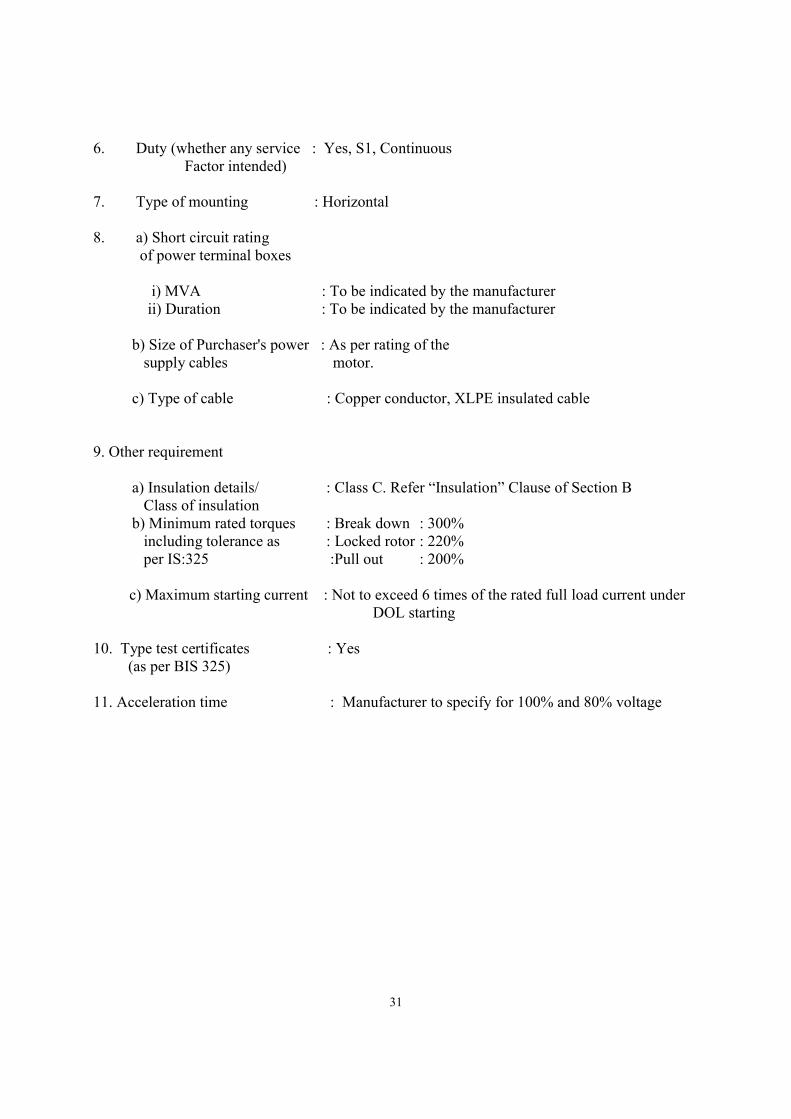
6. Duty (whether any service : Yes, S1, Continuous Factor intended)
7. Type of mounting : Horizontal 8. a) Short circuit rating of power terminal boxes i) MVA : To be indicated by the manufacturer ii) Duration : To be indicated by the manufacturer b) Size of Purchaser's power : As per rating of the supply cables motor. c) Type of cable : Copper conductor, XLPE insulated cable 9. Other requirement a) Insulation details/ : Class C. Refer “Insulation” Clause of Section B Class of insulation b) Minimum rated torques : Break down : 300% including tolerance as : Locked rotor : 220% per IS:325 :Pull out : 200% c) Maximum starting current : Not to exceed 6 times of the rated full load current under
DOL starting 10. Type test certificates : Yes (as per BIS 325) 11. Acceleration time : Manufacturer to specify for 100% and 80% voltage
32
ANNEXURE-4: MOTOR DATASHEET TO BE FILLED BY MOTOR MANUFACTURER AND SUBMITTED THROUGH PUMP MANUFACTURER
Sl.No. Particulars
1.0 Guaranteed operating conditions for the motor
1.1 Ambient temperature, 0C
1.2 Altitude, M
1.3 Humidity at 400C, (%)
1.4 Type of environment (corrosive/non-corrosive)
1.5 Location (indoors/outdoors)
1.6 Hazardous condition (Yes/No)
1.7 Rated voltage & its variations, (V)
1.8 Rated frequency & its variations, (Hz)
1.9 Permissible un-balance in supply voltage, (%)
1.10 Permissible harmonic content in supply voltage, (%)
1.11 Combined voltage & frequency variations, (%)
1.12 Number of phases
1.13 Method of system grounding.
1.14 Whether the motors are adequately designed to operate satisfactorily when supplied with power supply from electronic drives intended to be used for the driven equipment?
2.0 GENERAL
2.1 Make & Model no.
2.3 Application/Driven equipment
2.4 Method and type of coupling to driven equipment.
2.5 Type of motor
2.6 Frame size & design code no.
2.7 Mounting
2.8 Single shaft / double shaft extension.
2.9 Direction of rotation (viewed from drive end)
2.10 Rotation – uni /bi-directional
2.11 Reverse rotation stop provided?
2.12 Applicable standards/codes.
2.13 Stator winding connection
2.14 Winding resistance per phase*
3.0 RATING
3.1 Rated output (KW)
3.2 Rated speed (RPM)/Synchronous speed (RPM)
3.3 KW actually required by the drive equipment under specified operating conditions.
4.0 DUTY
4.1 Type of duty
5.0 STARTING
5.1 Method of starting
5.2 Starting current (% of full load current)
5.2.1 At rated voltage
33
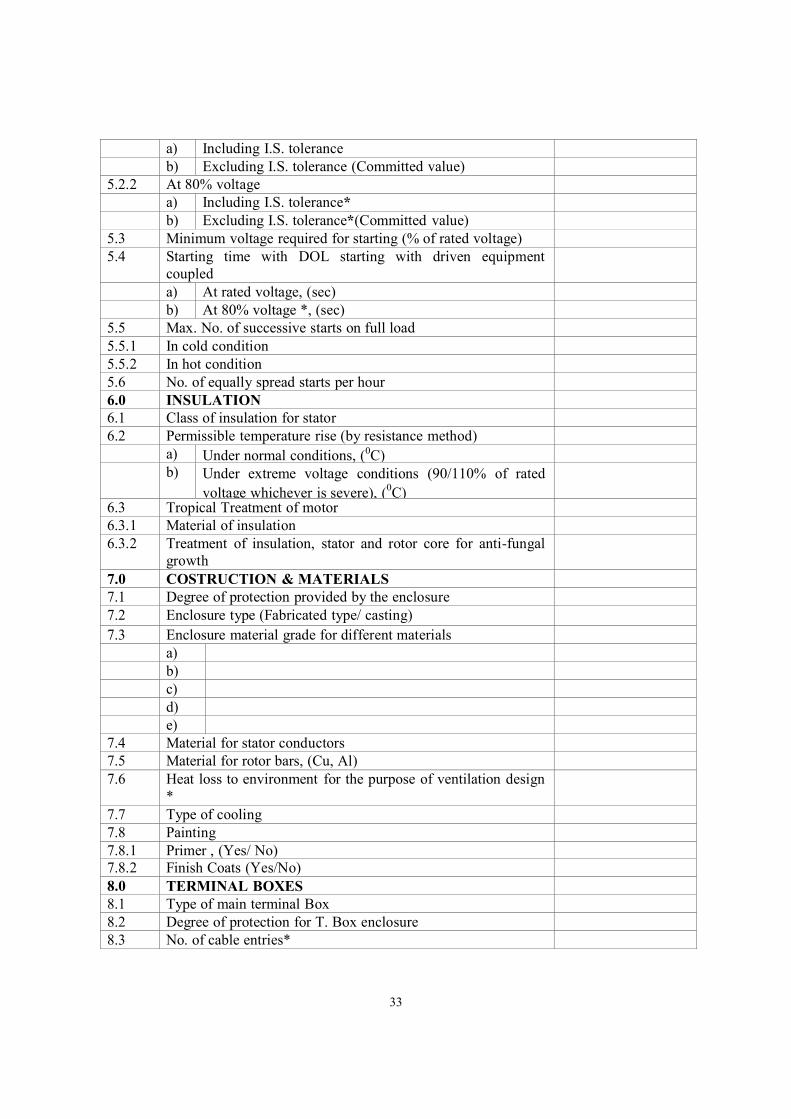
a) Including I.S. tolerance
b) Excluding I.S. tolerance (Committed value)
5.2.2 At 80% voltage
a) Including I.S. tolerance*
b) Excluding I.S. tolerance*(Committed value)
5.3 Minimum voltage required for starting (% of rated voltage)
5.4 Starting time with DOL starting with driven equipment coupled
a) At rated voltage, (sec)
b) At 80% voltage *, (sec)
5.5 Max. No. of successive starts on full load
5.5.1 In cold condition
5.5.2 In hot condition
5.6 No. of equally spread starts per hour
6.0 INSULATION
6.1 Class of insulation for stator
6.2 Permissible temperature rise (by resistance method)
a) Under normal conditions, (0C)
b) Under extreme voltage conditions (90/110% of rated
voltage whichever is severe), (0C)
6.3 Tropical Treatment of motor
6.3.1 Material of insulation
6.3.2 Treatment of insulation, stator and rotor core for anti-fungal growth
7.0 COSTRUCTION & MATERIALS
7.1 Degree of protection provided by the enclosure
7.2 Enclosure type (Fabricated type/ casting)
7.3 Enclosure material grade for different materials
a)
b)
c)
d)
e)
7.4 Material for stator conductors
7.5 Material for rotor bars, (Cu, Al)
7.6 Heat loss to environment for the purpose of ventilation design *
7.7 Type of cooling
7.8 Painting
7.8.1 Primer , (Yes/ No)
7.8.2 Finish Coats (Yes/No)
8.0 TERMINAL BOXES
8.1 Type of main terminal Box
8.2 Degree of protection for T. Box enclosure
8.3 No. of cable entries*
34
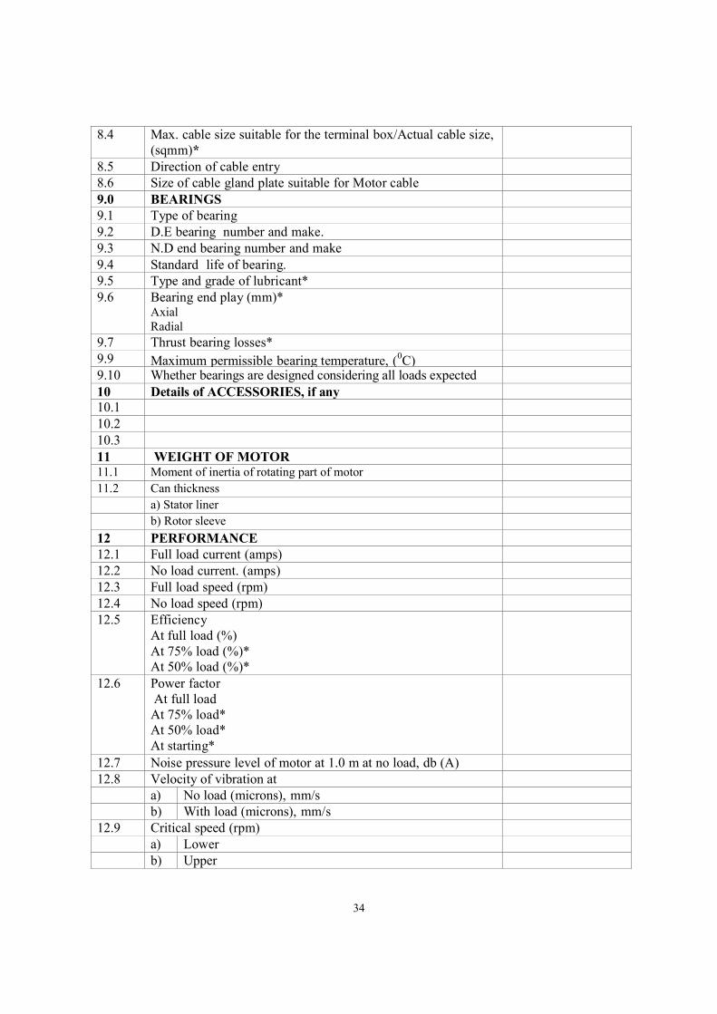
8.4 Max. cable size suitable for the terminal box/Actual cable size, (sqmm)*
8.5 Direction of cable entry
8.6 Size of cable gland plate suitable for Motor cable
9.0 BEARINGS
9.1 Type of bearing
9.2 D.E bearing number and make.
9.3 N.D end bearing number and make
9.4 Standard life of bearing.
9.5 Type and grade of lubricant*
9.6 Bearing end play (mm)* Axial Radial
9.7 Thrust bearing losses*
9.9 Maximum permissible bearing temperature, (0C)
9.10 Whether bearings are designed considering all loads expected during all operating conditions including seismic conditions (if
10 Details of ACCESSORIES, if any
10.1
10.2
10.3
11 WEIGHT OF MOTOR
11.1 Moment of inertia of rotating part of motor
11.2 Can thickness
a) Stator liner
b) Rotor sleeve
12 PERFORMANCE
12.1 Full load current (amps)
12.2 No load current. (amps)
12.3 Full load speed (rpm)
12.4 No load speed (rpm)
12.5 Efficiency At full load (%) At 75% load (%)* At 50% load (%)*
12.6 Power factor At full load At 75% load* At 50% load* At starting*
12.7 Noise pressure level of motor at 1.0 m at no load, db (A)
12.8 Velocity of vibration at
a) No load (microns), mm/s
b) With load (microns), mm/s
12.9 Critical speed (rpm)
a) Lower
b) Upper
35
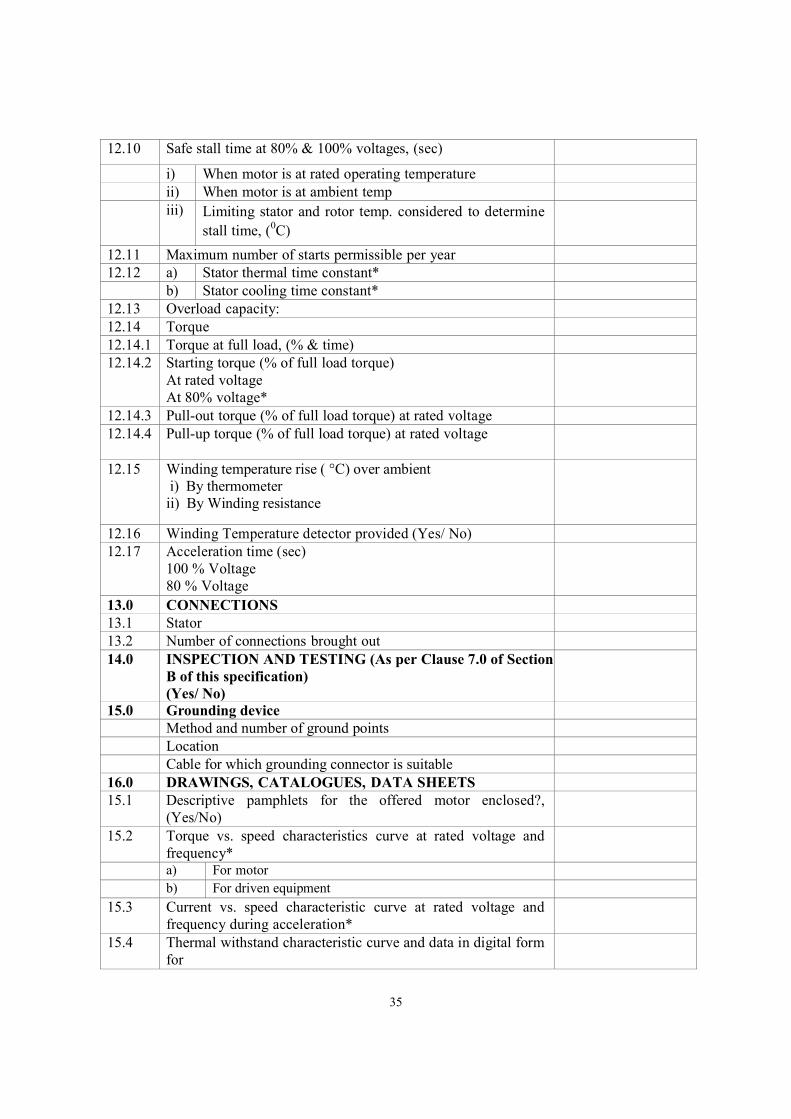
12.10 Safe stall time at 80% & 100% voltages, (sec)
i) When motor is at rated operating temperature
ii) When motor is at ambient temp
iii) Limiting stator and rotor temp. considered to determine
stall time, (0C)
12.11 Maximum number of starts permissible per year
12.12 a) Stator thermal time constant*
b) Stator cooling time constant*
12.13 Overload capacity:
12.14 Torque
12.14.1 Torque at full load, (% & time)
12.14.2 Starting torque (% of full load torque) At rated voltage At 80% voltage*
12.14.3 Pull-out torque (% of full load torque) at rated voltage
12.14.4 Pull-up torque (% of full load torque) at rated voltage
12.15 Winding temperature rise ( °C) over ambient i) By thermometer ii) By Winding resistance
12.16 Winding Temperature detector provided (Yes/ No)
12.17 Acceleration time (sec) 100 % Voltage 80 % Voltage
13.0 CONNECTIONS
13.1 Stator
13.2 Number of connections brought out
14.0 INSPECTION AND TESTING (As per Clause 7.0 of Section B of this specification) (Yes/ No)
15.0 Grounding device
Method and number of ground points
Location
Cable for which grounding connector is suitable
16.0 DRAWINGS, CATALOGUES, DATA SHEETS
15.1 Descriptive pamphlets for the offered motor enclosed?, (Yes/No)
15.2 Torque vs. speed characteristics curve at rated voltage and frequency*
a) For motor
b) For driven equipment
15.3 Current vs. speed characteristic curve at rated voltage and frequency during acceleration*
15.4 Thermal withstand characteristic curve and data in digital form for
36
a) Hot condition*
b) Cold condition*
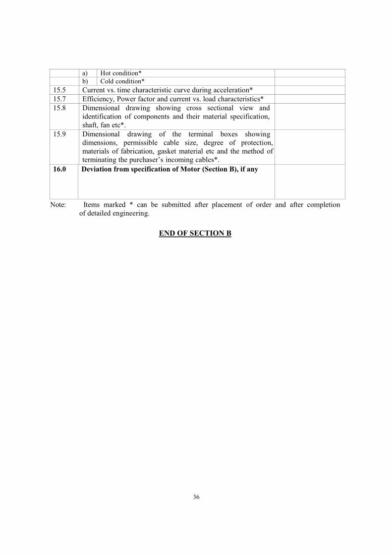
15.5 Current vs. time characteristic curve during acceleration*
15.7 Efficiency, Power factor and current vs. load characteristics*
15.8 Dimensional drawing showing cross sectional view and identification of components and their material specification, shaft, fan etc*.
15.9 Dimensional drawing of the terminal boxes showing dimensions, permissible cable size, degree of protection, materials of fabrication, gasket material etc and the method of terminating the purchaser’s incoming cables*.
16.0 Deviation from specification of Motor (Section B), if any
Note: Items marked * can be submitted after placement of order and after completion of detailed engineering.
END OF SECTION B
37
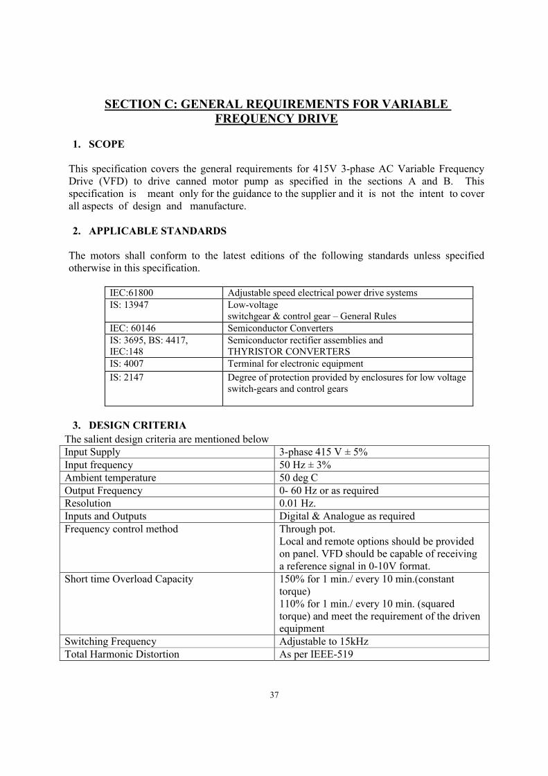
SECTION C: GENERAL REQUIREMENTS FOR VARIABLE FREQUENCY DRIVE
1. SCOPE
This specification covers the general requirements for 415V 3-phase AC Variable Frequency Drive (VFD) to drive canned motor pump as specified in the sections A and B. This specification is meant only for the guidance to the supplier and it is not the intent to cover all aspects of design and manufacture. 2. APPLICABLE STANDARDS
The motors shall conform to the latest editions of the following standards unless specified otherwise in this specification.
IEC:61800 Adjustable speed electrical power drive systems IS: 13947 Low-voltage
switchgear & control gear – General Rules IEC: 60146 Semiconductor Converters IS: 3695, BS: 4417, IEC:148
Semiconductor rectifier assemblies and THYRISTOR CONVERTERS
IS: 4007 Terminal for electronic equipment
IS: 2147
Degree of protection provided by enclosures for low voltage switch-gears and control gears
3. DESIGN CRITERIA
The salient design criteria are mentioned below Input Supply 3-phase 415 V ± 5% Input frequency 50 Hz ± 3% Ambient temperature 50 deg C Output Frequency 0- 60 Hz or as required Resolution 0.01 Hz. Inputs and Outputs Digital & Analogue as required Frequency control method Through pot.
Local and remote options should be provided on panel. VFD should be capable of receiving a reference signal in 0-10V format.
Short time Overload Capacity 150% for 1 min./ every 10 min.(constant torque) 110% for 1 min./ every 10 min. (squared torque) and meet the requirement of the driven equipment
Switching Frequency Adjustable to 15kHz Total Harmonic Distortion As per IEEE-519
38
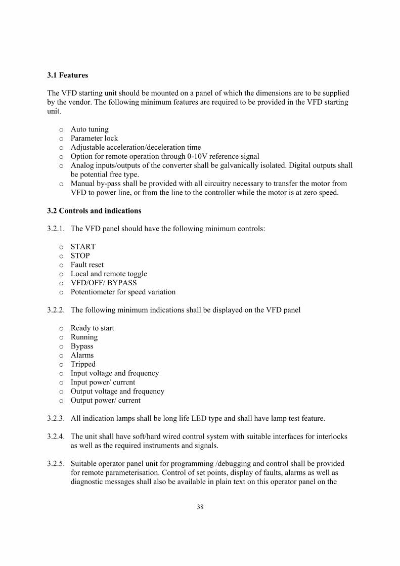
3.1 Features The VFD starting unit should be mounted on a panel of which the dimensions are to be supplied by the vendor. The following minimum features are required to be provided in the VFD starting unit.
o Auto tuning o Parameter lock o Adjustable acceleration/deceleration time o Option for remote operation through 0-10V reference signal o Analog inputs/outputs of the converter shall be galvanically isolated. Digital outputs shall
be potential free type. o Manual by-pass shall be provided with all circuitry necessary to transfer the motor from
VFD to power line, or from the line to the controller while the motor is at zero speed. 3.2 Controls and indications 3.2.1. The VFD panel should have the following minimum controls:
o START o STOP o Fault reset o Local and remote toggle o VFD/OFF/ BYPASS o Potentiometer for speed variation
3.2.2. The following minimum indications shall be displayed on the VFD panel
o Ready to start o Running o Bypass o Alarms o Tripped o Input voltage and frequency o Input power/ current o Output voltage and frequency o Output power/ current
3.2.3. All indication lamps shall be long life LED type and shall have lamp test feature. 3.2.4. The unit shall have soft/hard wired control system with suitable interfaces for interlocks
as well as the required instruments and signals. 3.2.5. Suitable operator panel unit for programming /debugging and control shall be provided
for remote parameterisation. Control of set points, display of faults, alarms as well as diagnostic messages shall also be available in plain text on this operator panel on the
39
panel door. It shall be sealed type with membrane switches & LCD display unit. This shall be user configurable type.
3.3 Protections All high speed electronic protections should also be available with the unit apart from self-diagnostic features. Few of them are listed below.
o Overcurrent protection and trip o Short circuit protection o Phase sequence failure protection o Single phasing prevention o Earth fault protection
3.4 EMC, Harmonics, and Filter Systems
3.4.1. The VFD system shall meet local and national standards for radio frequency emissions
and susceptibility.
3.4.2. Vendor shall calculate the total voltage harmonic distortion based on the power system data provided and the single line diagram for the installation. Particular attention should be paid to the effect that an increase in voltage harmonic distortion may have on existing electrical equipment. The maximum total harmonic distortion shall be approved by the Purchaser.
3.4.3. Harmonic current distortion values shall be according to IEEE 519 unless other limits are specified. In this Specification, the point of common coupling is defined as the first upstream bus that supplies other loads. Values of total harmonic voltage distortion at the point of common coupling shall be limited as follows: o Individual odd harmonics limited to less than 3 percent. o Individual even harmonics limited to less than 1.75 percent.
These values shall include any existing background harmonic levels provided by the Purchaser and shall be based on the minimum short-circuit level (maximum source impedance). Values of harmonic voltage as a percentage of fundamental shall be verified by Vendor during site testing of the VFD.
3.5 Noise level 3.5.1. The VFD system shall meet local and national standards for noise level and
susceptibility. 3.5.2. Noise level shall be limited to 85dbA when measured at one meter from edge of VFD
panel. 3.6 Construction
40
3.6.1. Power connections shall be of bolted type and mating surfaces shall be tinned copper. All busbars shall be adequately insulated for full circuit voltage. The VFD cubicle should have copper earth buses of adequate size running the entire cubicle height along the sides.
3.6.2. The cubicles housing the power semiconductors and drive level control system shall conform to IP 42 degree of protection for enclosures.
3.6.3. The panels shall be free standing, floor mounting type and comprise rigid welded structural frames enclosed completely with cold rolled steel sheet of thickness no less than 2.5 mm for front and rear portions and 2.0 mm for side, top and bottom portions. There shall be sufficient reinforcement to provide level surfaces, resistance to vibrations and rigidity during transportation and installation.
3.6.4. All doors, removable covers and panels shall be gasketed all around with neoprene gaskets.
3.6.5. Design, material selection and workmanship shall ensure in neat appearance inside and outside with no welds, rivets or belt heads apparent from outside and all exterior surfaces true and smooth.
3.6.6. All metal surfaces shall be thoroughly cleaned and degreased, pickled and phosphatised. Thereafter, a coat of phosphate paint and a coat of zinc chromate primer shall be applied. After removing all imperfections, all metal surfaces shall be sprayed with two coats of final paint as per colour shade RAL 7032. Final coat shall be of epoxy based. All unpainted parts shall be plated to prevent corrosion.
3.6.7. All equipment, accessories and wiring shall have fungus protection, involving special treatment of insulation and metal against fungus, insects and corrosion.
4. INSPECTION AND TESTING
4.1 The responsibility for inspection, certification, etc. of all materials, parts lies with the
Vendor.
4.2 The Vendor shall specify all of the inspection and testing requirements in the quality plan which shall identify the activities requiring the purchaser’s approval, review, witnessing etc.
4.3 Purchaser shall have the right to request additional inspections or tests to ensure that the equipment complies with the specification and all relevant codes & standards.
4.4 Manufacturer shall furnish valid Type Test Certificates of similar models along with the offer. Fresh type tests for the equipment are not needed, provided the Manufacturer can submit certificates that the equipment complies with all type tests as prescribed by IEC/IS Standard specifying the test requirements for that equipment.
4.5 The routine tests shall include but not necessarily limited to the following:
41
o Operation under service condition at pump manufacturer’s premises to ensure
accuracy of wiring, correctness of control scheme & proper functioning of the equipment.
o All wiring and current carrying part shall be given appropriate High Voltage test. o Primary current and voltage shall be applied to all instrument transformers.
4.6 Routine test shall be carried out on all equipment such as circuit breakers, instrument
transformers, relays, meters etc.
4.7 Routine Test certificates to be submitted for Equipment and its all auxiliaries. Type test certificate of similar equipment shall be submitted.
4.8 Vendor to furnish required copies of test certificates, reference documents, drawings, and instruction manuals before equipment are dispatched.
5. PACKING AND TRANSPORTATION
The manufacturer should ensure safe transportation of the VFD unit. The decision of supplying VFD and canned motor pump as separate units or as an assembly lies with the manufacturer.
END OF SECTION C