technical specification - optcl · technical specification index 1. general information and scope...
TRANSCRIPT
ODISHA POWER TRANSMISSION CORPORATION LIMITED
TECHNICAL SPECIFICATION
FOR
OPGW CABLE &
OPTIC FIBRE EQUIPMENT
TECHNICAL SPECIFICATION
INDEX
1. General Information and Scope
2. OPGW cabling and associated hardware & fittings
2.1 Fibre Optic Cabling
2.1.1 Required Optical Fibre Characteristics
2.1.1.1 Physical Characteristics
2.1.1.2 Attenuation
2.1.2 Fibre Optic Cable Construction
2.1.2.1 Transmission Line Details
2.1.2.2 Optical Fibre Cable Link Lengths
2.1.2.3 Optical Fibre Identification
2.1.2.4 Buffer Tube
2.1.2.5 Optical Fibre Strain & Sag-tension chart
2.1.2.6 Cable Materials
2.1.2.6.1 Filling Materials
2.1.2.6.2 Metallic Members
2.1.2.6.3 Marking, Packaging and Shipping
2.1.2.7 OPGW cable installation requirements
2.1.2.8 Optical Ground Wire (OPGW)
2.1.2.8.1 Central Fibre Optic Unit
2.1.2.8.2 Basic Construction
2.1.2.8.3 Breaking Strength
2.1.2.8.4 Electrical and Mechanical Requirements
2.1.2.8.5 Operating conditions
2.1.2.8.6 Installation
2.1.2.8.7 Installation Hardware
2.1.3 Fibre Optic Splice Enclosures (Joint Box)
2.1.3.1 Optical Fibre Splices
2.1.4 Fibre Optic Approach Cables
2.1.4.1 Basic Construction
2.1.4.2 Jacket Construction & Material
2.1.4.3 Optical, Electrical and Mechanical Requirements
2.1.5 Installation of Approach Cable
2.1.6 Optical Fibre Termination and Splicing
2.1.6.1 Fibre Optic Distribution Panel
2.1.6.2 Optical Fibre Connectors
2.1.7 Service Loops
2.1.8 Methodology for Installation and Termination
2.1.9 Cable Raceways
2.2 Type testing and FAT
2.2.1 Type testing
3. Optic Fibre Equipment and Network Configuration
3.1 Introduction 3.2 General Network Characteristics 3.2.1 Description 3.2.2 Functional Requirement 3.2.3 General Systems Requirements System Synchronisation System maintainability System Upgradability and Expandability
Equipment Availability General Equipment Characteristics
Revision Levels and Modifications
Equipment Capacities
Redundancy Requirements & Protection Scheme
Lost Signal Recovery
Equipment Lifespan
General Site Considerations
Fibre Optic Link Lengths
Fibre Optic Transmission System
3.3.1 SDH Equipment
3.3.1.1 Functional Requirement
3.3.1.2 Redundancy and Protection
3.3.1.3 Service Channel
3.3.1.4 Supervision and Alarms 3.3.1.5 Synchronisation 3.3.1.6 Electrical and Optical I/O Characteristics and General Parameters 3.3.2 Optical Link Performance Requirements 3.3.2.1 Link Budget Calculations
Link Performance
3.3.2.3 FODP to SDH Equipment
3.4 Termination Equipment Subsystem Functional Description First Order (Primary) Multiplexing Drop & Insert Primary Multiplexing Channel Banks (Mux, Drop/Insert)
3.4.2.3 Subscriber Line Units\Subscriber Line Interface Cards Digital Access Cross connect System Required DACS Applications Menus and Reports MDF, DDF and Cabling

3.5.1 MDF and DDF Patching Facilities 3.5.1.1 Digital Distribution Frame Functional Requirements 3.5.1.2 Main Distribution Frames 3.6 Patch Cords 3.7 Telecommunication Management Network / Network Management System 3.7.1 Performance Management 3.8 Communication Channel Requirement and Integration
3.9 Craft Terminal
3.9.1 Hardware Requirement 3.10 General Software/Firmware Requirements 3.10.1 Operating System Software 3.10.2 Applications Software 3.10.3 Software Utilities 3.10.4 Revisions, Upgrades, Maintainability 3.10.5 Help
1.2 General Information and Scope
1.2.1 The transmission lines where OPGW shall be commissioned, are of 132
kV voltage class or 220 kV voltage class. The bill of quantities for the same is
specified in the BPS/ BOQ.
1.2.3 : The quantities of hardware fittings such as tension assembly, suspension assembly, vibration damper, etc required for the stringing of the
OPGW are not reflected in the BPS/BOQ. The contractor has to assess the quantities of such hardware fittings required for the OPGW stringing per km as per the tower schedule and profile survey of the transmission line.
1.2.4 : The bidder shall submit along with the Bid the sag-tension chart of
the offered OPGW, based on the profile, for verification and approval by the employer. 2. OPGW cabling and associated hardware & fittings This section describes the functional & technical specifications of OPGW cabling and
associated hardware & fittings.
Fibre Optic Cabling
This section defines the requirements for G.652D Dual-window Single mode (DWSM)
telecommunications grade fibre optic cable. Bidders shall furnish with their bids,
detailed descriptions of the fibres & cable(s) proposed.
All optical fibre cabling including fibre itself and all associated installation hardware
shall have a minimum guaranteed design life span of 25 years. Documentary evidence
in support of guaranteed life span of cable & fibre shall be submitted by the Contractor
during detailed engineering.
Required Optical Fibre Characteristics
This section describes the characteristics of optical fibre to be provided under this
specification.
Physical Characteristics
Dual-Window Single mode (DWSM), G.652D optical fibres shall be provided in the
fibre optic cables. DWSM optical fibres shall meet the requirements defined in Table 1-
1(a).
Attenuation
The attenuation coefficient for wavelengths between 1525 nm and 1575 nm shall not
exceed the attenuation coefficient at 1550 nm by more than 0.05 dB/km. The
attenuation coefficient between 1285 nm and 1330 nm shall not exceed the
attenuation coefficient at 1310 nm by more than 0.05 dB/km. The attenuation of the
fibre shall be distributed uniformly throughout its length such that there are no point
discontinuities in excess of 0.10 dB. The fibre attenuation characteristics specified in
table 1-1 (a) shall be “guaranteed” fibre attenuation of any & every fibre reel.
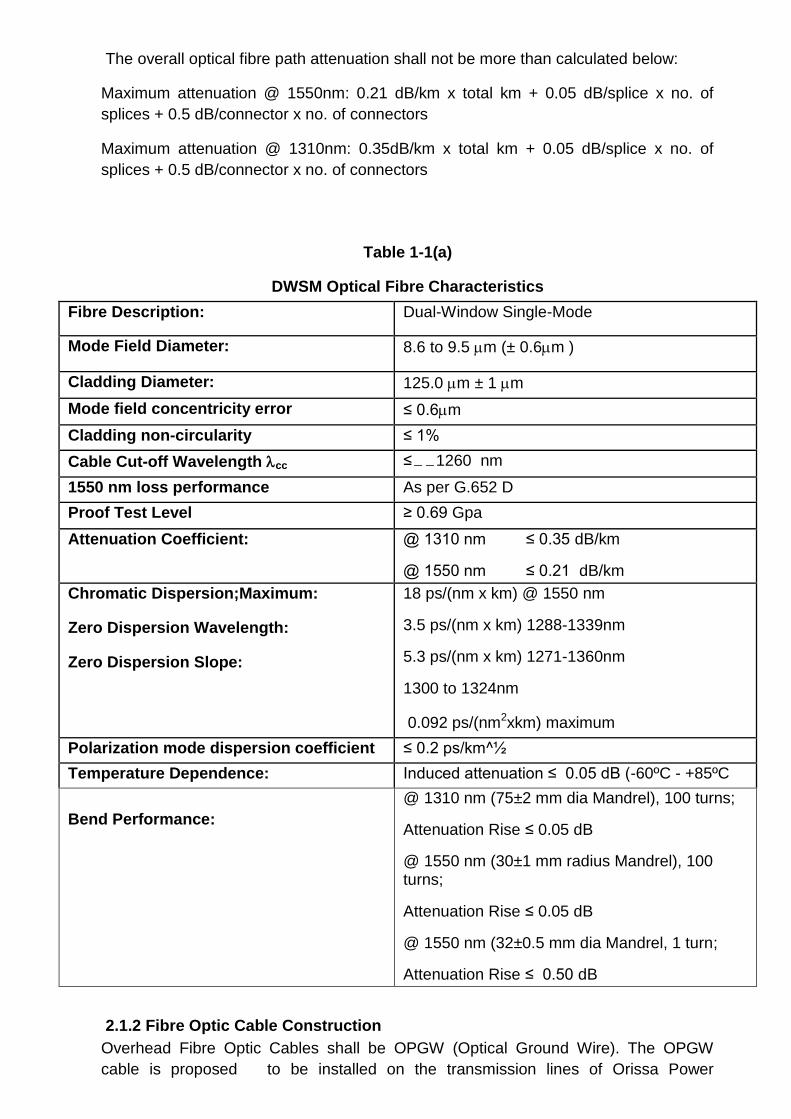
The overall optical fibre path attenuation shall not be more than calculated below:
Maximum attenuation @ 1550nm: 0.21 dB/km x total km + 0.05 dB/splice x no. of
splices + 0.5 dB/connector x no. of connectors
Maximum attenuation @ 1310nm: 0.35dB/km x total km + 0.05 dB/splice x no. of
splices + 0.5 dB/connector x no. of connectors
2.1.2 Fibre Optic Cable Construction
Overhead Fibre Optic Cables shall be OPGW (Optical Ground Wire). The OPGW
cable is proposed to be installed on the transmission lines of Orissa Power
Table 1-1(a)
DWSM Optical Fibre Characteristics
Fibre Description: Dual-Window Single-Mode
Mode Field Diameter: 8.6 to 9.5 m (± 0.6m )
Cladding Diameter: 125.0 m ± 1 m
Mode field concentricity error ≤ 0.6m
Cladding non-circularity ≤ 1%
Cable Cut-off Wavelength cc ≤ 1260 nm
1550 nm loss performance As per G.652 D
Proof Test Level ≥ 0.69 Gpa
Attenuation Coefficient: @ 1310 nm ≤ 0.35 dB/km
@ 1550 nm ≤ 0.21 dB/km
Chromatic Dispersion;Maximum:
Zero Dispersion Wavelength:
Zero Dispersion Slope:
18 ps/(nm x km) @ 1550 nm
3.5 ps/(nm x km) 1288-1339nm
5.3 ps/(nm x km) 1271-1360nm
1300 to 1324nm
0.092 ps/(nm2xkm) maximum
Polarization mode dispersion coefficient ≤ 0.2 ps/km^½
Temperature Dependence: Induced attenuation ≤ 0.05 dB (-60ºC - +85ºC
Bend Performance:
@ 1310 nm (75±2 mm dia Mandrel), 100 turns;
Attenuation Rise ≤ 0.05 dB
@ 1550 nm (30±1 mm radius Mandrel), 100 turns;
Attenuation Rise ≤ 0.05 dB
@ 1550 nm (32±0.5 mm dia Mandrel, 1 turn;
Attenuation Rise ≤ 0.50 dB
Transmission Corporation Ltd. (OPTCL). The design of cable shall account for the
varying operating and environmental conditions that the cable shall experience while in
service. The OPGW cable to be supplied shall be designed to meet the overall
requirements of all the transmission lines. Normally the tower span of the lines shall
not exceed 600 m, however, some of the spans may be up to around 1000 m or more.
The exact details shall be collected by the Contractor during survey. To meet the
overall requirement of all the transmission lines, the contractor may offer more than
one design without any additional cost to OPTCL , in case span length of 600 m is
found during survey. It may also be noted that some of the transmission lines route
may be added during the engineering stage.
Transmission Line Details
The list of transmission lines are indicated in Annexure-1 . The details required for
cable design etc. shall be collected by the Contractor during survey.
Optical Fibre Cable Link Lengths
The estimated optical fibre link lengths are provided in Appendices as transmission
line route length. However, the Contractor shall supply & install the optical fibre cable
as required based on detailed site survey to be carried out by the Contractor during the
project execution. The Contractor shall verify the transmission line route length during
the survey and the Contract price shall be adjusted accordingly. For the purpose of
payment, the optical fibre link lengths are defined as transmission line route lengths
from Gantry at one terminating station to the Gantry in the other terminating station.
The actual cable lengths to be delivered shall take into account various factors such as
sag, service loops, splicing, working lengths & wastage etc. and no additional payment
shall be payable in this regard. The unit rate for FO cable quoted in the Bid price
Schedules shall take into account all such factors.
Optical Fibre Identification
Individual optical fibres within a fibre unit and fibre units shall be identifiable in
accordance with EIA/TIA 598 or IEC 60304 or Bellcore GR-20 colour-coding scheme.
Colouring utilized for colour coding optical fibres shall be integrated into the fibre
coating and shall be homogenous. The colour shall not bleed from one fibre to another
and shall not fade during fibre preparation for termination or splicing.
Each cable shall have traceability of each fibre back to the original fibre manufacturer's
fibre number and parameters of the fibre. If more than the specified number of fibres
are included in any cable, the spare fibres shall be tested by the cable manufacturer
and any defective fibres shall be suitably bundled, tagged and identified at the factory
by the vendor.
Buffer Tube
Loose tube construction shall be implemented. The individually coated optical fibre(s)
shall be surrounded by a buffer for protection from physical damage during fabrication,
installation and operation of the cable. The fibre coating and buffer shall be strippable
for splicing and termination. Each fibre unit shall be individually identifiable utilizing
colour coding. Buffer tubes shall be filled with a water-blocking gel.

Optical Fibre Strain & Sag-Tension chart
The fibre optic cable shall be designed and installed such that the optical fibres
experience no strain under all loading conditions defined in IS 802. Zero fibre strain
condition shall apply even after a 25 year cable creep.
For the purpose of this specification, the following definitions shall apply:
Maximum Working Tension (MWT) is defined as the maximum cable tension at which there is no fibre strain. The no fibre strain condition is defined as fibre strain of less than or equal to 0.05%, as determined by direct measurements through IEC/ ETSI (FOTP) specified optical reflectometry techniques. The Cable strain margin is defined as the maximum cable strain at which there is no fibre strain. The cable Maximum Allowable Tension (MAT) is defined as the maximum tension experienced by the Cable under the worst case loading condition. The cable max strain is defined as the maximum strain experienced by the Cable under the worst case loading condition. The cable Every Day Tension (EDT) is defined as the maximum cable tension on any span under normal conditions. The Ultimate /Rated Tensile Strength (UTS/ RTS/ breaking strength) is defined as the maximum tensile load applied and held constant for one minute at which the specimen shall not break. While preparing the Sag-tension charts for the OPGW cable the following conditions
shall be met:
The Max Allowable Tension (MAT) / max strain shall be less than or equal to the MWT/ Strain margin of the cable. The sag shall not exceed the earth wire sag in all conditions. The Max Allowable Tension shall also be less than or equal to 0.4 times the UTS. The 25 year creep at 25% of UTS (creep test as per IEEE 1138) shall be such that the 25 year creep plus the cable strain at Max Allowable Tension (MAT) is less than or equal to the cable strain margin. The everyday tension (EDT) shall not exceed 20% of the UTS for the OPGW cable.
The Sag-tension chart of OPGW cable indicating the maximum tension, cable strain
and sag shall be calculated and submitted along with the bid under various conditions
mentioned below:
53° C , no wind and no ice 32° C, no wind and no ice 0°C, no wind and no ice 32° C, full wind and no ice 32° C, 75% full wind and no ice 0° C, 2/3rd / 36% of full wind (IS 802:1977/1995) The above cases shall be considered for the spans from 100 m to 600 m or higher span length in the range of 50 m spans. Max. vertical sag, max. tension and max sag at 0° C & no wind shall be considered for in line with the design parameter of transmission line. The typical details are indicated in the Appendices. The full wind load shall be considered as the design wind load for all the specified transmission lines as per relevant IS 802 version and the sag-tension chart shall be submitted considering the transmission lines. In case of any span higher than 600m, suitable OPGW cable meeting sag-tension requirement of transmission line shall also be

provided by the Contractor. The Contractor shall submit the stringing chart for review of OPTCL.
Cable Materials
The materials used for optical fibre cable construction, shall meet the following
requirements:
Filling Materials
The interstices of the fibre optic unit and cable shall be filled with a suitable compound
to prohibit any moisture ingress or any water longitudinal migration within the fibre
optic unit or along the fibre optic cable. The water tightness of the cable shall meet or
exceed the test performance criteria as per IEC 60794-1-F-5.
The filling compound used shall be a non-toxic homogenous waterproofing compound
that is free of dirt and foreign matter, non hygroscopic, electrically nonconductive and
non-nutritive to fungus. The compound shall also be fully compatible with all cable
components it may come in contact with and shall inhibit the generation of hydrogen
within the cable.
The waterproofing filling materials shall not affect fibre coating, colour coding, or
encapsulant commonly used in splice enclosures, shall be dermatologically safe, non-
staining and easily removable with a non-toxic cleaning solvent.
Metallic Members
When the fibre optic cable design incorporates metallic elements in its construction, all
metallic elements shall be electrically continuous.
Marking, Packaging and Shipping
This section describes the requirements for marking, packaging and shipping the
overhead fibre optic cable.
(a) Drum Markings: Each side of every reel of cable shall be permanently marked in
white lettering with the vendors' address, the Purchaser’s destination address, cable
part number and specification as to the type of cable, length, number of fibres, a
unique drum number including the name of the transmission line & segment no.,
factory inspection stamp and date.
(b) Cable Drums: All optical fibre cabling shall be supplied on strong drums
provided with lagging of adequate strength, constructed to protect the cabling against
all damage and displacement during transit, storage and subsequent handling during
installation. Both ends of the cable shall be sealed as to prevent the escape of filling
compounds and dust & moisture ingress during shipment and handling. Spare cable
caps shall be provided with each drum as required.
The spare cable shall be supplied on sturdy, corrosion resistant, steel drums suitable
for long periods of storage and re-transport & handling.
There shall be no factory splices allowed within a continuous length of cable. Only one
continuous cable length shall be provided on each drum. The lengths of cable to be
supplied on each drum shall be determined by a "schedule" prepared by the
Contractor.

OPGW cable installation requirements
Most of the OPGW fibre optic cables to be installed under this project shall be installed under live line conditions, i.e. with all the circuits of the transmission line charged to their rated voltage. However, some of OPGW cables may be installed in off-line conditions. The tentative bill of quantities for both live-line as well as off-line OPGW cable system installations have been specified in the appendices and the actual quantities for both types shall be finalised during project execution after detailed survey. The OPGW cable shall be installed at the top of the tower by replacing the existing ground wire. The Contractor shall carry out re-tensioning of the existing earth wire wherever required to maintain the adequate clearances for live line stringing of fibre optic cables. However, in exceptional cases installation of OPGW cable below conductor may also be considered on low voltage lines which shall be decided during detailed engineering.
Optical Ground Wire (OPGW)
OPGW cable construction shall comply with IEEE-1138, 2009. The cable provided
shall meet both the construction and performance requirements such that the ground
wire function, the optical fibre integrity and optical transmission characteristics are
suitable for the intended purpose. The cable shall consist of optical fibre units as
defined in this specification. There shall be no factory splices within the cable structure
of a continuous cable length.
The composite fibre optic overhead ground wire shall be made up of multiple buffer
tubes embedded in a water tight aluminium/aluminium alloy/stainless steel with
aluminium coating protective central fibre optic unit surrounded by concentric-lay
stranded metallic wires in single or multiple layers. Each buffer tube shall have
maximum 12 no. of fibres. All fibres in single buffer tube or directly in central fibre optic
unit is not acceptable. The dual purpose of the composite cable is to provide the
electrical and physical characteristics of conventional overhead ground wire while
providing the optical transmission properties of optical fibre
Central Fibre Optic Unit
The central fibre optic unit shall be designed to house and protect multiple buffered
optical fibre units from damage due to forces such as crushing, bending, twisting,
tensile stress and moisture. The central fibre optic unit and the outer stranded metallic
conductors shall serve together as an integral unit to protect the optical fibres from
degradation due to vibration and galloping, wind and ice loadings, wide temperature
variations, lightning and fault current, as well as environmental effects which may
produce hydrogen.
The OPGW design of dissimilar materials such as stainless steel tube with aluminium
or aluminium –clad-steel wire strands are not allowed. Central fibre optic unit may be
of aluminium or stainless steel tube with aluminium protective coating. In case of
aluminium protective coating, the coating must completely cover the tubes leaving no
exposed areas of tubing that can make electrical contact either directly or indirectly
through moisture, contamination, protrusions, etc with the surrounding stranded wires.
The tube may be fabricated as a seamless tube, seam welded, or a tube without a
welded seam.
Basic Construction
The cable construction shall conform to the applicable requirements of this
specification, applicable clauses of IEC 61089 related to stranded conductors and
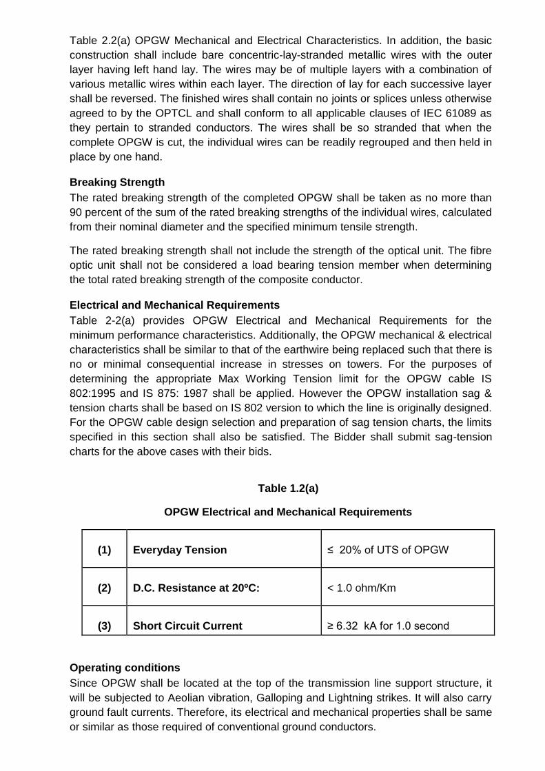
Table 2.2(a) OPGW Mechanical and Electrical Characteristics. In addition, the basic
construction shall include bare concentric-lay-stranded metallic wires with the outer
layer having left hand lay. The wires may be of multiple layers with a combination of
various metallic wires within each layer. The direction of lay for each successive layer
shall be reversed. The finished wires shall contain no joints or splices unless otherwise
agreed to by the OPTCL and shall conform to all applicable clauses of IEC 61089 as
they pertain to stranded conductors. The wires shall be so stranded that when the
complete OPGW is cut, the individual wires can be readily regrouped and then held in
place by one hand.
Breaking Strength
The rated breaking strength of the completed OPGW shall be taken as no more than
90 percent of the sum of the rated breaking strengths of the individual wires, calculated
from their nominal diameter and the specified minimum tensile strength.
The rated breaking strength shall not include the strength of the optical unit. The fibre
optic unit shall not be considered a load bearing tension member when determining
the total rated breaking strength of the composite conductor.
Electrical and Mechanical Requirements
Table 2-2(a) provides OPGW Electrical and Mechanical Requirements for the
minimum performance characteristics. Additionally, the OPGW mechanical & electrical
characteristics shall be similar to that of the earthwire being replaced such that there is
no or minimal consequential increase in stresses on towers. For the purposes of
determining the appropriate Max Working Tension limit for the OPGW cable IS
802:1995 and IS 875: 1987 shall be applied. However the OPGW installation sag &
tension charts shall be based on IS 802 version to which the line is originally designed.
For the OPGW cable design selection and preparation of sag tension charts, the limits
specified in this section shall also be satisfied. The Bidder shall submit sag-tension
charts for the above cases with their bids.
Table 1.2(a)
OPGW Electrical and Mechanical Requirements
(1)
Everyday Tension
≤ 20% of UTS of OPGW
(2)
D.C. Resistance at 20ºC:
< 1.0 ohm/Km
(3)
Short Circuit Current
≥ 6.32 kA for 1.0 second
Operating conditions
Since OPGW shall be located at the top of the transmission line support structure, it
will be subjected to Aeolian vibration, Galloping and Lightning strikes. It will also carry
ground fault currents. Therefore, its electrical and mechanical properties shall be same
or similar as those required of conventional ground conductors.

Installation
OPGW installed under live line condition, i.e. with all circuits charged to the rated line
voltage as specified in this section shall be generally in accordance with the IEEE
Guide to the Installation of Overhead Transmission Line Conductors (IEEE STD. 524
with latest revisions), with additional instructions and precautions for live line working
and fibre optic cable handling. Some of the cable may be installed in off-line condition
also. The stringing procedure shall be submitted by the Contractor to OPTCL for
approval prior to stringing .
A tower structural analysis shall be carried out by the Contractor, based on the
relevant data to be provided by OPTCL, to ensure that with the replacement of existing
earth wire with the OPGW cable, the tower members remain within the statutory safety
limits as per Indian Electricity rules and if required the Contractor shall carry out the
tower strengthening as necessary. The OPGW cable sections shall normally be
terminated & spliced only on tension towers. In exceptional circumstances, and on
OPTCL specific approval, cable may be terminated on Suspension towers, but in this
case tower strength shall be examined to ensure that tower loads are within safe limits
and if required, necessary tower strengthening shall be carried out by the Contractor.
Installation Hardware
The scope of supply of the optical cable includes the assessment, supply and
installation of all required fittings and hardware such as Tension assembly,
Suspension assembly, Vibration dampers, Reinforcing rods, Earthing clamps,
Downlead clamps, splice enclosure etc. The Bidder shall provide documentation
justifying the adequacy and suitability of the hardware supplied. The quantity of
hardware & fittings to meet any eventuality during site installation min@ 1% shall also
be provided as part of set/km for each transmission line without any additional cost to
OPTCL. The Contractor shall determine the exact requirements of all accessories
required to install and secure the OPGW.
The OPGW hardware fittings and accessories shall follow the general requirements
regarding design, materials, dimensions & tolerances, protection against corrosion and
markings as specified in clause 4.0 of EN 61284: 1997 (IEC 61284). The shear
strength of all bolts shall be at least 1.5 times the maximum installation torque. The
OPGW hardware & accessories drawing & Data Requirement Sheets (DRS) document
shall consist of three parts: (1) A technical particulars sheet (2) An assembly drawing
i.e. level 1 drawing and (3) Component level drawings i.e. level 2 & lower drawings. All
component reference numbers, dimensions and tolerances, bolt tightening torques &
shear strength and ratings such as UTS, slip strength etc shall be marked on the
drawings.
The fittings and accessories described herein are indicative of installation hardware typically used for OPGW installations and shall not necessarily be limited to the following:
(a) Suspension Assemblies: Preformed armour grip suspension clamps and
aluminium alloy armour rods/ reinforcing rods shall be used. The suspension clamps
shall be designed to carry a vertical load of not less than 25 KN. The suspension
clamps slippage shall occur between 12kN and 17 kN as measured in accordance with
type test procedures . The Contractor shall supply all the components of the

suspension assembly including shackles, bolts, nuts, washers, split pins, etc. The total
drop of the suspension assembly shall not exceed 150 mm (measured from the centre
point of attachment to the centre point of the OPGW). The design of the assembly
shall be such that the direction of run of the OPGW shall be the same as that of the
conductor.
(b) Dead End Clamp Assemblies: All dead end clamp assemblies shall
preferably be of performed armoured grip type and shall include all necessary
hardware for attaching the assembly to the tower strain plates. Dead end clamps shall
allow the OPGW to pass through continuously without cable cutting. The slip strength
shall be rated not less than 95% of the rated tensile strength of the OPGW.
(c) Clamp Assembly Earthing Wire: Earthing wire consisting of a 1500 mm length of
aluminium or aluminium alloy conductor equivalent in size to the OPGW shall be used
to earth suspension and dead end clamp assemblies to the tower structure. The
earthing wire shall be permanently fitted with lugs at each end. The lugs shall be
attached to the clamp assembly at one end and the tower structure at the other.
(d) Structure Attachment Clamp Assemblies: Clamp assemblies used to attach
the OPGW to the structures, shall have two parallel grooves for the OPGW, one on
either side of the connecting bolt. The clamps shall be such that clamping
characteristics do not alter adversely when only one OPGW is installed. The tower
attachment plates shall locate the OPGW on the inside of the tower and shall be
attached directly to the tower legs/cross-members without drilling or any other
structural modifications.
(e) Vibration Dampers: Vibration dampers type 4R Stockbridge or equivalent,
having four (4) different frequencies spread within the Aeolian frequency bandwidth
corresponding to wind speed of 1m/s to 7 m/s, shall be used for suspension and
tension points in each span. The Contractor shall determine the exact numbers and
placement(s) of vibration dampers through a detailed vibration analysis as specified in
technical specifications.
One damper minimum on each side per OPGW cable for suspension
points and two dampers minimum on each side per OPGW cable for tension points
shall be used for nominal design span of 400 meters. For all other ruling spans, the
number of vibration damper shall be based on vibration analysis.
The clamp of the vibration damper shall be made of high strength aluminum
alloy of type LM-6. It shall be capable of supporting the damper and prevent damage
or chaffing of the conductor during erection or continued operation. The clamp shall
have smooth and permanent grip to keep the damper in position on the OPGW cable
without damaging the strands or causing premature fatigue failure of the OPGW cable
under the clamp. The clamp groove shall be in uniform contact with the OPGW cable
over the entire clamping surface except for the rounded edges. The groove of the
clamp body and clamp cap shall be smooth, free from projections, grit or other
materials which could cause damage to the OPGW cable when the clamp is installed.
Clamping bolts shall be provided with self locking nuts and designed to prevent
corrosion of threads or loosening in service.
The messenger cable shall be made of high strength galvanised
steel/stain less steel. It shall be of preformed and post formed quality in order to
prevent subsequent drop of weight and to maintain consistent flexural stiffness of the
cable in service. The messenger cable other than stainless steel shall be hot dip
galvanised in accordance with the recommendations of IS:4826 for heavily coated
wires.
The damper mass shall be made of hot dip galvanised mild steel/cast
iron or a permanent mould cast zinc alloy. All castings shall be free from defects such
as cracks, shrinkage, inclusions and blow holes etc. The surface of the damper
masses shall be smooth.
The damper clamp shall be casted over the messenger cable and offer
sufficient and permanent grip on it. The messenger cable shall not slip out of the grip
at a load less than the mass pull-off value of the damper. The damper masses made of
material other-than zinc alloy shall be fixed to the messenger cable in a suitable
manner in order to avoid excessive stress concentration on the messenger cables
which shall cause premature fatigue failure of the same. The messenger cable ends
shall be suitably and effectively sealed to prevent corrosion. The damper mass made
of zinc alloy shall be casted over the messenger cable and have sufficient and
permanent grip on the messenger cable under all service conditions.
The contractor must indicate the clamp bolt tightening torque to ensure
that the slip strength of the clamp is maintained between 2.5 kN and 5 kN. The clamp
when installed on the OPGW cable shall not cause excessive stress concentration on
the OPGW cable leading to permanent deformation of the OPGW strands and
premature fatigue failure in operation.
The vibration analysis of the system, with and without damper and
dynamic characteristics of the damper as detailed in Technical Specification, shall
have to be submitted. The technical particulars for vibration analysis and damping
design of the system are as follows:
The damper placement chart for spans ranging from 100m to 1100m shall
be submitted by the Bidder. Placement charts should be duly supported with
relevant technical documents and sample calculations.
Sl No. Description Technical Particulars
1 Span Length in meters
Ruling design span :
Maximum span :
Minimum Span :
400 meters
1100 meters
100 meters
2 Configuration : As per Specifications
3 Tensile load in each : As per sag tension calculations
4 Armour rods used : Standard preformed armour rods/AGS
5 Maximum permissible
dynamic strain :
+/- 150 micro strains
The damper placement charts shall include the following
(1) Location of the dampers for various combinations of spans and line
tensions clearly indicating the number of dampers to be installed per OPGW cable
per span.
(2) Placement distances clearly identifying the extremities between which
the distances are to be measured.
(3) Placement recommendation depending upon type of suspension clamps
(viz Free center type/Armour grip type etc.)
(4) The influence of mid span compression joints, repair sleeves and armour rods
(standard and AGS) in the placement of damper
2.1.3 Fibre Optic Splice Enclosures (Joint Box)
All splices shall be encased in Fibre Optic Splice Enclosures. Suitable splice
enclosures shall be provided to encase the optical cable splices in protective, moisture
and dust free environment. Splice enclosures shall comply to ingress protection class
IP 66 or better. The splice enclosures shall be designed for the storage and protection
of required number of optical fibre splices and equipped with sufficient number of
splice trays for splicing all fibres in the cable. No more than 12 fibres shall be
terminated in a single splice tray. They shall be filled with suitable encapsulate that is
easily removable should re-entry be required into the enclosures.
Splice enclosures shall be suitable for outdoor use with each of the cable types
provided under this contract. Splice enclosures shall be appropriate for mounting on
transmission line towers above anti-climb guard levels at about 10 metres from top of
the tower and shall accommodate pass-through splicing. The actual mounting height
and location shall be finalised after Survey. Contractor shall be responsible for splicing
of fibres and installation of splice enclosures.
2.1.3.1 Optical Fibre Splices
Splicing of the optical fibre cabling shall be minimized through careful Contractor
planning. There shall be no mid-span splices allowed. All required splices shall be
planned to occur on tower structures. All optical fibre splicing shall comply with the
following:
(a) All fibre splices shall be accomplished through fusion splicing.
(b) Each fibre splice shall be fitted with a splice protection sheath fitted over the
final splice.
(c) All splices and bare fibre shall be neatly installed in covered splice trays.
(d) For each link, bi-directional attenuation of single mode fusion splices, shall not
average more than 0.05 dB and no single splice loss shall exceed 0.1 dB when
measured at 1550 nm.
(e) For splicing, fibre optic cable service loops of adequate length shall be provided
so that all splices occurring at tower structures can be performed at ground level.

Fibre Optic Approach Cables
For purposes of this specification, a fibre optic approach cable is defined as the Armoured underground fibre optic cable required to connect Overhead Fibre Optic Cable (OPGW) between the final in line splice enclosure on the gantry / tower forming the termination of the fibre cable on the power line and the Fibre Optic Distribution Panel (FODP) installed within the building. The estimated fibre optic approach cabling length requirements are indicated in the Annexure-V(A) & Annexure-V(B). However, the Contractor shall supply & install the optical fibre approach cable as required based on detailed site survey to be carried out by the Contractor during the project execution and the Contract price shall be adjusted accordingly.
Basic Construction
The cable shall be suitable for direct burial, laying in trenches & PVC/Hume ducts, laying under false flooring and on indoor or outdoor cable raceways.
Jacket Construction & Material
The Approach Cable shall be a UV resistant, rodent proof, armoured cable with
metallic type of armouring. The outer cable jacket for approach cable shall consist of
carbon black polyethylene resin to prevent damage from exposure to ultra-violet light,
weathering and high levels of pollution. The jacket shall conform to ASTM D1248 for
density.
Optical, Electrical and Mechanical Requirements
Approach cable shall contain fibres with identical optical/ physical characteristics as
those in the OPGW cables. The cable core shall comprise of tensile strength
member(s), fibre support/bedding structure, core wrap/bedding, and an overall
impervious jacket.
The fibre optic approach cable shall have a minimum outer jacket thickness of 3.0 milli meters and shall meet the following requirements.
i. Fire retardant and no acid gas evolution. ii. Resistance to ultra-violet deterioration. iii. Anti-moisture penetration.
1 Number of optical fibres in OFAC 24
2 Mode DWSM (Dual Window Single
Mode)
3 Optimised wavelength ( nm ) 1550 / 1310
4 Mode field diameter (μm) 9.2 +/- 0.5
5 Outside (Clad ) diameter (μm) : 125 +/- 0.5
6 Attenuation 0.22 dB / Km Max. at 1550
nm
0.36 dB / Km Max at 1310 nm
7 Chromatic Dispersion
At 1310 nm
At 1550 nm
2.8 ps/ (nm.km)
18 ps/ (nm.km)
8 Polarisation Mode dispersion ≤ 0.1 ps Sqrt.Km
2.1.5 Installation of Approach Cable
The existing cable trenches/ cable raceways proposed to be used shall be identified in
the survey report. The Contractor shall make its best effort to route the cable through
the existing available cable trenches. Where suitable existing cable trenches are not
available, suitable alternatives shall be provided after OPTCL approval. However, the
approach cable shall be laid in the HDPE pipe in all condition.
Suitable provisions shall be made by the Contractor to ensure adequate safety
earthing and insulated protection for the approach cable.
All required fittings, supports, accessories, ducts, inner ducts, conduits, risers and any
item not specially mentioned but required for laying and installation of approach
cables shall be supplied and installed by the Contractor.
Optical Fibre Termination and Splicing
Optical fibre terminations shall be installed in Fibre Optic Distribution Panels (FODP)
designed to provide protection for fibre splicing of preconnectorized pigtails and to
accommodate connectorized termination and coupling of the fibre cables. The
Contractor shall provide rack /wall mounted Fibre Optic Distribution Panels (FODPs)
sized as indicated in the appendices and shall terminate the fibre optic cabling up to
the FODPs. The location of FODP rack shall be fixed by the Contractor, with the
Employer’s approval.
Fibre Optic Distribution Panel
At each location requiring the termination of at least one fibre within a cable, all fibres
within that cable shall be connectorized and terminated in Fibre Optic Distribution
Panels in a manner consistent with the following:
(a) All fibre optic terminations shall be housed using FODPs provisioned with splice
organizers and splice trays. All fibres within a cable shall be fusion spliced to
preconnectorized pigtails and fitted to the "Back-side" of the provided fibre optic
couplings.
(b) FODPs shall be suitable for use with each of the cable types provided as part of
this contract. FODPs shall accommodate pass-through splicing and fibre terminations.
(c) FODPs for indoor use shall be supplied in suitable cabinets/racks with locking
arrangement
(d) All FODPs shall be of corrosion resistant, robust construction and shall allow
both top or bottom entry for access to the splice trays. Ground lugs shall be provided
on all FODPs and the Contractor shall ensure that all FODPs are properly grounded.
The FODP shall meet or exceed ingress protection class IP55 specifications.
(e) Flexible protection shall be provided to the patch cord bunches going out from
FODP to other equipment.
Optical Fibre Connectors
Optical fibres shall be connectorised with FC-PC type connectors preferably.
Alternatively connector with matching patch cord shall also be acceptable. Fibre optic
couplings supplied with FODPs shall be appropriate for the fibre connectors to be
supported. There shall be no adapters.
2.1.7 Service Loops

For purposes of this specification, cable and fibre service loops are defined as slack
(extra) cable and fibre provided for facilitating the installation, maintenance and repair
of the optical fibre cable plant.
(a) Outdoor Cable Service Loops: In-line splice enclosures installed outdoors and
mounted on the utility towers, shall be installed with sufficient fibre optic cable service
loops such that the recommended minimum bend radius is maintained while allowing
for installation or maintenance of the cable to be performed in a controlled environment
at ground level.
(b) Indoor Cable Service Loops: FODPs shall provide at least three (3) metres of
cable service loop. Service loops shall be neatly secured and stored, coiled such that
the minimum recommended bend radius' are maintained.
(c) Fibre Units Service Loops: For all fibre optic cable splicing, the cable shall be
stripped back a sufficient length such that the fan-out of fibre units shall provide for at
least one (1) metre of fibre unit service loop between the stripped cable and the
bare fibre fan-out.
(d) Pigtail Service Loops : Connectorised pigtails spliced to bare fibres shall provide at
least 1 metre of service loop installed in the FODP fibre organizer and at least one (1)
metre of service loop to the couplings neatly stored behind the FODP coupling panels.
(e) Fibre Service Loops : At least 0.5 metre of bare fibre service loop shall be
provided on each side of all fibre splices. The bare fibre service loops shall be neatly
and safely installed inside covered splice trays.
2.1.8 Methodology for Installation and Termination
All optical fibre cable termination, installation, stringing and handling plans, guides and
procedures, and engineering analysis (e.g. tension, sag, vibration etc.) shall be
submitted to OPTCL for review and approval in the engineering/design phase of the
project, prior to establishing the final cable lengths for manufacture. Installation
procedures including details of personnel and time required shall be documented in
detail and submitted to OPTCL for approval. All installation practices shall be field
proven and ISO accredited.
All cable segments shall include service loops as specified in this specification .The
maximum allowable stringing tension, maximum allowable torsional shear stress,
crush strength and other physical parameters of the cable shall not be exceeded. The
preventative measures to be taken shall be documented in detail and submitted to
OPTCL in advance of installation.
Optical fibre attenuation shall be measured after installation and before splicing. Any
increase in attenuation or step discontinuity in attenuation shall not be acceptable and
shall constitute a cable segment failure. In the event of cable damage or any fibre
damage, the complete section (tension location to tension location) shall be replaced
as mid-span joints are not acceptable.
Any or all additional steel work or modifications required to attach the fibre cabling to
the overhead transmission/ distribution line towers shall also be carried out by the
Contractor. It shall be the Contractors responsibility to provide adequate
communications among all crew members and support staff to ensure safe and
successful installations
2.1.9 Cable Raceways
To the extent possible, existing cable raceways shall be utilised. The Contractor is
required to provide and install any additional indoor cable raceways which may be
required for proper implementation of the fibre optic cabling system. This requirement
shall be finalised during survey. The cable raceways shall conform to the following:
(a) All cable raceways shall be sized to support full loading requirements plus at least
a 200% safety loading factor.
(b) Indoor cable raceways shall be fabricated from construction grade aluminum,
galvanized iron or anodized sheet metal or any other suitable material approved by
OPTCL. Suitable anti-corrosion measures shall be provided. Steel fabricated raceways
shall be finished inside and out, treated to resist rust and to form a metal-to- paint
bond.
(c) Mechanical construction drawings of the cable raceways shall be submitted for
OPTCL’s information & review.
2.0 Inspection & Testing Requirement All materials furnished and all work performed under this Contract shall be inspected and tested. Deliverables shall not be shipped until all required inspections and tests have been completed, and all deficiencies have been corrected to comply with this Specification and approved for shipment by the Employer. Except where otherwise specified, the Contractor shall provide all manpower and materials for tests, including testing facilities, logistics, power and instrumentation, and replacement of damaged parts. The costs shall be borne by the Contractor and shall be deemed to be included in the contract price.
The entire cost of testing for factory, production tests and other test during manufacture specified herein shall be treated as included in the quoted unit price of materials including the expenses of Inspector/Employer’s representative as per clause-41 of ITB..
Acceptance or waiver of tests shall not relieve the Contractor from the responsibility to furnish material in accordance with the specifications.
All tests shall be witnessed by the Employer and/or its authorized representative (hereinafter referred to as the Employer) unless the Employer authorizes testing to proceed without witness. The Employer representative shall sign the test form indicating approval of successful tests.
Should any inspections or tests indicate that specific item does not meet Specification requirements, the appropriate items shall be replaced, upgraded, or added by the Contractor as necessary to correct the noted deficiencies at no cost to the Employer. After correction of a deficiency, all necessary retests shall be performed to verify the effectiveness of the corrective action.

The Employer reserves the right to require the Contractor to perform, at the Employer's expense, any other reasonable test(s) at the Contractor's premises, on site, or elsewhere in addition to the specified Type, Acceptance, Routine, or Manufacturing tests to assure the Employer of specification compliance.
3.1 Testing Requirements
Following are the requirements of testing :
1. Type Testing 2. Factory Acceptance Testing 3. Site Acceptance Testing
3.1.1 Type Testing "Type Tests" shall be defined as those tests which are to be carried out to prove the design, process of manufacture and general conformity of the materials to this Specification. Type Testing shall comply with the following:
(a) All cable & equipment being supplied shall conform to type tests as per
technical specification.
(b) The test reports submitted shall be of the tests conducted within last seven (7) years for OPGW cable prior to the date of proposal/offer submitted. In case the test reports are older than seven (7) years for OPGW cable on the date of proposal/offer, the Contractor shall repeat these tests at no extra cost to the Employer.
(c) The Contractor shall submit, within 30 days of Contract Award, copies of test reports for all of the Type Tests that are specified in the specifications and that have previously ( before Contract award) been performed. These reports may be accepted by the Employer only if they apply to materials and equipment that are essentially identical to those due to be delivered under the Contract and only if test procedures and parameter values are identical to those specified in this specifications carried out at accredited labs and witnessed by third party / customer’s representatives.
In the event of any discrepancy in the test reports or any type tests not carried out, same shall be carried out by Contractor without any additional cost implication to the Employer.
In case the Type Test is required to be carried out, then following shall be applicable:-
(d) Type Tests shall be certified or performed by reputed laboratories using
material and equipment data sheets and test procedures that have been
approved by the Employer. The test procedures shall be formatted as
defined in the technical specifications and shall include a complete list of
the applicable reference standards and submitted for Employer approval at
least four (4) weeks before commencement of test(s). The Contractor shall
provide the Employer at least 30 days written notice of the planned
commencement of each type test.

(e) The Contractor shall provide a detailed schedule for performing all specified
type tests. These tests shall be performed in the presence of a representative of the Employer.
(f) The Contractor shall ensure that all type tests can be completed within the
time schedule offered in his Technical Proposal.
(g) In case of failure during any type test, the Supplier is either required to manufacture a fresh sample lot and repeat all type tests successfully or repeat that particular type test(s) at least three times successfully on the samples selected from the already manufactured lot at his own expenses. In case a fresh lot is manufactured for testing then the lot already manufactured shall be rejected.
3.1.2 Type Test Samples
The Contractor shall supply equipment/material for sample selection only after the Quality Assurance Plan has been approved by the Employer. The sample material shall be manufactured strictly in accordance with the approved Quality Assurance Plan. The Contractor shall submit for Employer approval, the type test sample selection procedure. The selection process for conducting the type tests shall ensure that samples are selected at random. For optical fibres/ Fibre Optic cables, at least three reels/ drums of each type of fibre/cable proposed shall be offered for selection. For FO cable installation hardware & fittings at least ten (10) samples shall be offered for selection. For Splice enclosures at least three samples shall be offered for selection.
3.1.3 List of Type Tests
The type testing shall be conducted on the following items
(a) Optical fibres (b) OPGW Cable (c) OPGW Cable fittings (d) Vibration Damper (e) Splice Enclosure (Joint Box) (f) Approach Cable
3.1.3.1 Type Tests for Optical Fibres
The type tests listed below in table 2-1 shall be conducted on DWSM fibres to be supplied as part of overhead cables. The tests specific to the cable type are listed in subsequent sections.

Table 3-1 Type Tests For Optical Fibres
S. No. Test Name Acceptance Criteria Test procedure
1 Attenuation As per Section-01 of TS IEC 60793-1-40
Or EIA/TIA 455-78A
2 Attenuation Variation with As per Section-01 of TS IEC 60793-1-40
3 Attenuation at Water Peak IEC 60793-1-40
Or EIA/TIA 455-78A
4 Temp. Cycling As per Section-01 of TS IEC 60793-1-52
(Temp dependence of Or EIA/TIA 455-3A, 2
Attenuation) cycles
5 Attenuation With Bending As per Section-01 of TS IEC 60793-1-47
(Bend Performance) Or EIA/TIA 455-62A
6 Mode Field dia. As per Section-01 of TS
IEC 60793-1-45 Or
EIA/TIA 455-
164A/167A/174
7 Chromatic Dispersion As per Section-01 of TS IEC 60793-1-42 Or
EIA/TIA 455-
168A/169A/175A
8 Cladding Diameter As per Section-01 of TS IEC 60793-1-20 Or
EIA/TIA 455-176
9 Point Discontinuities of
attenuation 10 Core -Clad concentricity
error
11 Fibre Tensile
Proof Testing
As per Section-01 of TS
As per Section-01 of TS
As per Section-01 of TS
IEC 60793-1-40 Or EIA/TIA 455-59 IEC 60793-1-20 Or EIA/TIA 455-176
IEC 60793-1-30 Or EIA/TIA 455-31B
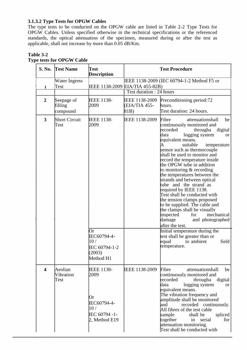
3.1.3.2 Type Tests for OPGW Cables The type tests to be conducted on the OPGW cable are listed in Table 2-2 Type Tests for OPGW Cables. Unless specified otherwise in the technical specifications or the referenced standards, the optical attenuation of the specimen, measured during or after the test as applicable, shall not increase by more than 0.05 dB/Km.
Table 3-2 Type tests for OPGW Cable
S. No. Test Name Test Test Procedure
Description
1
Water Ingress
Test IEEE 1138-2009
IEEE 1138-2009 (IEC 60794-1-2 Method F5 or
EIA/TIA 455-82B)
: Test duration : 24 hours
2 Seepage of IEEE 1138- IEEE 1138-2009 Preconditioning period:72
filling 2009 (EIA/TIA 455- hours.
compound 81B) Test duration: 24 hours.
3 Short Circuit IEEE 1138- IEEE 1138-2009 Fibre attenuation shall be
Test 2009 continuously monitored and
recorded through a digital
data logging system or
equivalent means.
A suitable temperature
sensor such as thermocouple
shall be used to monitor and
record the temperature inside
the OPGW tube in addition
to monitoring & recording
the temperatures between the
strands and between optical
tube and the strand as
required by IEEE 1138.
Test shall be conducted with
the tension clamps proposed
to be supplied. The cable and
the clamps shall be visually
inspected for mechanical
damage and photographed
after the test.
Or Initial temperature during the
IEC60794-4- test shall be greater than or
10 / equal to ambient field
IEC 60794-1-2 temperature.
(2003)
Method H1
4 Aeolian IEEE 1138- IEEE 1138-2009 Fibre attenuation shall be
Vibration 2009 continuously monitored and
Test recorded through a digital
data logging system or
equivalent means.
Or
The vibration frequency and
amplitude shall be monitored
IEC60794-4-
and recorded continuously.
10 /
All fibres of the test cable
IEC 60794 -1-
sample shall be spliced
2, Method E19 together in serial for
attenuation monitoring.
Test shall be conducted with
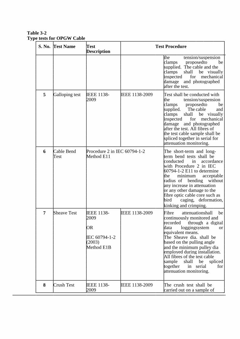
Table 3-2 Type tests for OPGW Cable
S. No. Test Name Test Test Procedure Description
the tension/suspension
clamps proposed to be supplied. The cable and the
clamps shall be visually inspected for mechanical damage and photographed
after the test.
5 Galloping test IEEE 1138- IEEE 1138-2009 Test shall be conducted with 2009 the tension/suspension
clamps proposed to be supplied. The cable and clamps shall be visually inspected for mechanical damage and photographed
after the test. All fibres of
the test cable sample shall be
spliced together in serial for
attenuation monitoring.
6 Cable Bend Procedure 2 in IEC 60794-1-2 The short-term and long- Test Method E11 term bend tests shall be
conducted in accordance with Procedure 2 in IEC
60794-1-2 E11 to determine
the minimum acceptable radius of bending without any increase in attenuation
or any other damage to the
fibre optic cable core such as
bird caging, deformation, kinking and crimping.
7 Sheave Test IEEE 1138- IEEE 1138-2009 Fibre attenuation shall be 2009 continuously monitored and
recorded through a digital OR data logging system or equivalent means.
IEC 60794-1-2 The Sheave dia. shall be
(2003) based on the pulling angle
Method E1B and the minimum pulley dia employed during installation.
All fibres of the test cable
sample shall be spliced together in serial for attenuation monitoring.
8 Crush Test IEEE 1138- IEEE 1138-2009 The crush test shall be 2009 carried out on a sample of
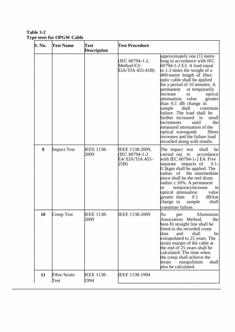
Table 3-2 Type tests for OPGW Cable
S. No. Test Name Test Test Procedure Description
approximately one (1) metre
(IEC 60794-1-2, long in accordance with IEC
Method E3/ 60794-1-2 E3. A load equal
EIA/TIA 455-41B) to 1.3 times the weight of a
400-metre length of fibre
optic cable shall be applied
for a period of 10 minutes. A
permanent or temporarily
increase in optical attenuation value greater than 0.1 dB change in
sample shall constitute failure. The load shall be
further increased in small increments until the measured attenuation of the
optical waveguide fibres increases and the failure load
recorded along with results.
9 Impact Test IEEE 1138- IEEE 1138-2009, The impact test shall be 2009 (IEC 60794-1-2 carried out in accordance E4/ EIA/TIA 455- with IEC 60794-1-2 E4. Five
25B) separate impacts of 0.1- 0.3kgm shall be applied. The
radius of the intermediate piece shall be the reel drum
radius ± 10%. A permanent
or temporary increase in optical attenuation value greater than 0.1 dB/km change in sample shall constitute failure.
10 Creep Test IEEE 1138- IEEE 1138-2009 As per Aluminium 2009 Association Method, the best-fit straight line shall be
fitted to the recorded creep
data and shall be extrapolated to 25 years. The
strain margin of the cable at
the end of 25 years shall be
calculated. The time when
the creep shall achieve the
strain margin limits shall also be calculated.
11 Fibre Strain IEEE 1138- IEEE 1138-1994
Test 1994

Table 3-2 Type tests for OPGW Cable
S. No. Test Name Test Test Procedure
Description
12 Strain Margin IEEE 1138- IEEE 1138-2009
Test 2009
13 Stress strain IEEE 1138- IEEE 1138-2009
Test 2009
14 Cable Cut-off IEEE 1138- IEEE 1138-1994
wavelength 1994
Test
15 Temperature IEEE 1138- IEEE 1138-2009
Cycling Test 2009 Or IEC 60794-1-2, Method F1
16 Corrosion EIA/TIA 455-16A
(Salt Spray)
Test
17 Tensile IEC 60794-1-2 E1 / EIA/TIA 455-33B The test shall be
Performance conducted on a sample of
Test sufficient length in
accordance with IEC
60794-1-2 E1. The
attenuation variation shall
not exceed 0.05 dB/Km
up to 90% of RTS of fibre
optic cable.
The load shall be
increased at a steady rate
up to rated tensile
strength and held for one
(1) minute. The fibre
optic cable sample shall
not fail during the period.
The applied load shall
then be increased until the
failing load is reached and
the value recorded.
18 Lightning IEC 60794-4-10 / The OPGW cable
construction shall be
Test IEC 60794-1-2 (2003)
tested in accordance with
IEC 60794-1-2, Method
H2 for Class 1.
19 DC On a fibre optic cable sample of minimum 1 metre length, two
Resistance contact clamps shall be fixed with a predetermined bolt torque. The
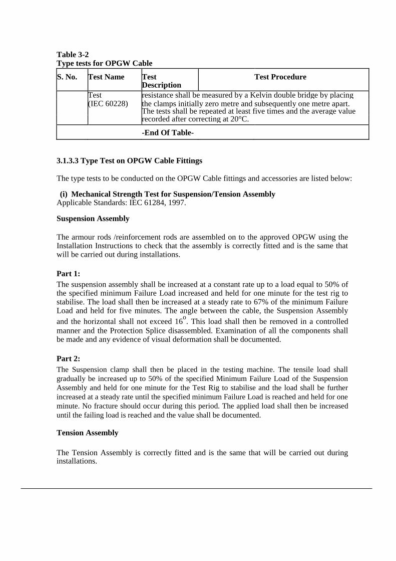
Table 3-2 Type tests for OPGW Cable
S. No. Test Name Test Test Procedure Description
Test resistance shall be measured by a Kelvin double bridge by placing (IEC 60228) the clamps initially zero metre and subsequently one metre apart. The tests shall be repeated at least five times and the average value recorded after correcting at 20°C.
-End Of Table-
3.1.3.3 Type Test on OPGW Cable Fittings The type tests to be conducted on the OPGW Cable fittings and accessories are listed below: (i) Mechanical Strength Test for Suspension/Tension Assembly
Applicable Standards: IEC 61284, 1997. Suspension Assembly
The armour rods /reinforcement rods are assembled on to the approved OPGW using the Installation Instructions to check that the assembly is correctly fitted and is the same that will be carried out during installations.
Part 1: The suspension assembly shall be increased at a constant rate up to a load equal to 50% of the specified minimum Failure Load increased and held for one minute for the test rig to stabilise. The load shall then be increased at a steady rate to 67% of the minimum Failure Load and held for five minutes. The angle between the cable, the Suspension Assembly
and the horizontal shall not exceed 16o. This load shall then be removed in a controlled
manner and the Protection Splice disassembled. Examination of all the components shall be made and any evidence of visual deformation shall be documented.
Part 2: The Suspension clamp shall then be placed in the testing machine. The tensile load shall
gradually be increased up to 50% of the specified Minimum Failure Load of the Suspension
Assembly and held for one minute for the Test Rig to stabilise and the load shall be further
increased at a steady rate until the specified minimum Failure Load is reached and held for one
minute. No fracture should occur during this period. The applied load shall then be increased
until the failing load is reached and the value shall be documented. Tension Assembly
The Tension Assembly is correctly fitted and is the same that will be carried out during installations.
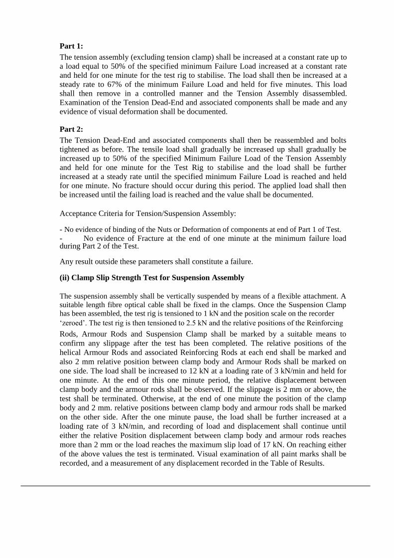
Part 1: The tension assembly (excluding tension clamp) shall be increased at a constant rate up to
a load equal to 50% of the specified minimum Failure Load increased at a constant rate
and held for one minute for the test rig to stabilise. The load shall then be increased at a
steady rate to 67% of the minimum Failure Load and held for five minutes. This load
shall then remove in a controlled manner and the Tension Assembly disassembled.
Examination of the Tension Dead-End and associated components shall be made and any
evidence of visual deformation shall be documented.
Part 2: The Tension Dead-End and associated components shall then be reassembled and bolts
tightened as before. The tensile load shall gradually be increased up shall gradually be
increased up to 50% of the specified Minimum Failure Load of the Tension Assembly
and held for one minute for the Test Rig to stabilise and the load shall be further
increased at a steady rate until the specified minimum Failure Load is reached and held
for one minute. No fracture should occur during this period. The applied load shall then
be increased until the failing load is reached and the value shall be documented.
Acceptance Criteria for Tension/Suspension Assembly: - No evidence of binding of the Nuts or Deformation of components at end of Part 1 of Test. - No evidence of Fracture at the end of one minute at the minimum failure load during Part 2 of the Test. Any result outside these parameters shall constitute a failure. (ii) Clamp Slip Strength Test for Suspension Assembly
The suspension assembly shall be vertically suspended by means of a flexible attachment. A suitable length fibre optical cable shall be fixed in the clamps. Once the Suspension Clamp has been assembled, the test rig is tensioned to 1 kN and the position scale on the recorder ‘zeroed’. The test rig is then tensioned to 2.5 kN and the relative positions of the Reinforcing Rods, Armour Rods and Suspension Clamp shall be marked by a suitable means to
confirm any slippage after the test has been completed. The relative positions of the
helical Armour Rods and associated Reinforcing Rods at each end shall be marked and
also 2 mm relative position between clamp body and Armour Rods shall be marked on
one side. The load shall be increased to 12 kN at a loading rate of 3 kN/min and held for
one minute. At the end of this one minute period, the relative displacement between
clamp body and the armour rods shall be observed. If the slippage is 2 mm or above, the
test shall be terminated. Otherwise, at the end of one minute the position of the clamp
body and 2 mm. relative positions between clamp body and armour rods shall be marked
on the other side. After the one minute pause, the load shall be further increased at a
loading rate of 3 kN/min, and recording of load and displacement shall continue until
either the relative Position displacement between clamp body and armour rods reaches
more than 2 mm or the load reaches the maximum slip load of 17 kN. On reaching either
of the above values the test is terminated. Visual examination of all paint marks shall be
recorded, and a measurement of any displacement recorded in the Table of Results.

Acceptance Criteria: The Suspension Clamp has passed the Slip Test if the following conditions are met:
No slippage* shall occur at or below the specified minimum slip load.
* Definition of no slippage in accordance with IEC 61284, 1997:- Any relative movement less than 2 mm is accepted. The possible couplings or elongations produced by the cable as a result of the test itself are not regarded as slippage.
Slippage shall occur between the specified maximum and minimum slip load of 12 - 17 kN.
There shall be no slippage of the Reinforcing Rods over the cable, and no slippage of the Armour Rods over the Reinforcing Rods.
The relative movement (i.e. more than 2 mm between Armour Rods & Clamp body) between minimum 12 kN and maximum slip 17 kN, shall be considered as slip.
The Armour Rods shall not be displaced from their original lay or damaged**.
** Definition of no damage in accordance with convention expressed in IEC 61284: 1997 no damage, other than surface flattening of the strands shall occur.
Any result outside these parameters is a failure.
(iii) Slip Strength Test of Tension Clamp
Tension clamps shall be fitted on an 8 m length of fibre optic cable on both ends. The
assembly shall be mounted on a tensile testing machine and anchored in a manner similar
to the arrangement to be used in service. A tensile load shall gradually be applied up to 20
% of the RTS of OPGW. Displacement transducers shall be installed to measure the
relative movement between the OPGW relative to the Reinforcing Rods and Tension
Dead -End relative to Reinforcing Rods. In addition, suitable marking shall be made on
the OPGW and Dead-End to confirm grip. The load shall be gradually increased at a
constant rate up to 50 % of the UTS and the position scale of the recorder is zeroed. The
load shall then gradually increased up to 95 % of the UTS and maintained for one minute.
After one minute pause, the load shall be slowly released to zero and the marking
examined and measured for any relative movement.
Acceptance Criteria:
- No movement* shall occur between the OPGW and the Reinforcing Rods, or between
the Reinforcing Rods and the Dead-End assembly. - No failure or damage or disturbance to the lay of the Tension Dead-End, Reinforcing
Rods or OPGW.

* Definition of no movement as defined in IEC 61284: Any relative movement less than 2 mm is accepted. The possible couplings or elongations produced by the conductor as a result of the test itself are not regarded as slippage.
Any result outside these parameters shall constitute a failure.
(iv) Grounding Clamp and Structure Mounting Clamp Fit Test
For structure mounting clamp, one series of tests shall be conducted with two fibre optic
cables installed, one series of tests with one fibre optic cable installed in one groove, and
one series of tests with one fibre optic cable in the other groove. Each clamp shall be
installed including clamping compound as required on the fibre optic cable. The nut shall
be tightened on to the bolt by using torque wrench with a torque of 5.5 kgm or supplier's
recommended torque and the tightened clamp shall be held for 10 minutes. After the test
remove the fibre optic cable and examine all its components for distortion, crushing or
breaking. Also the fibre optic cable shall be checked to ensure free movement within the
core using dial callipers to measure the diameter of the core tube. The material shall be
defined as failed if any visible distortion, crushing, cracking or breaking of the core tube
is observed or the fibre optic cable within the core tube is not free to move, or when the
diameter of the core tube as measured at any location in the clamped area is more than 0.5
mm larger or smaller of the core diameter as measured outside the clamped area.
(v) Structure Mounting Clamp Strength Test
The clamp and mounting assembly shall be assembled on a vertical 200 mm x 200 mm angle and a short length of fibre optic cable installed. A vertical load of 200 kg shall be applied at the end of the mounting clamp and held for 5 minutes. Subsequently, the load shall be increased to 400 kg and held for 30 seconds. Any visible distortion, slipping or breaking of any component of the mounting clamp or assembly shall constitute failure.
3.1.3.4 Type Test on Vibration Damper
The testing standard of vibration damper for OPGW shall be as per applicable international standard i.e. IEC 61897.
(a) Dynamic Characteristic Test
The damper shall be mounted with its clamp tightened with torque recommended by the manufacturer on shaker table capable of simulating sinusoidal vibrations for Critical Aeolian Vibration frequency band ranging from 0.18/d to 1.4/d – where d is the OPGW cable diameter in meters. The damper assembly shall be vibrated vertically with a ±1 mm amplitude from 5 to 15 Hz frequency and beyond 15 Hz at 0.5 mm to determine following characteristics with the help of suitable recording instruments.
(i) Force Vs frequency
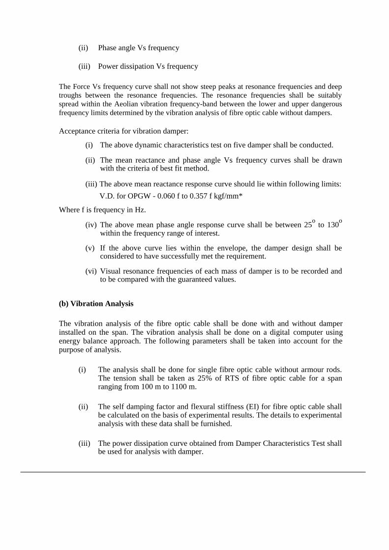
(ii) Phase angle Vs frequency
(iii) Power dissipation Vs frequency
The Force Vs frequency curve shall not show steep peaks at resonance frequencies and deep
troughs between the resonance frequencies. The resonance frequencies shall be suitably
spread within the Aeolian vibration frequency-band between the lower and upper dangerous
frequency limits determined by the vibration analysis of fibre optic cable without dampers.
Acceptance criteria for vibration damper:
(i) The above dynamic characteristics test on five damper shall be conducted.
(ii) The mean reactance and phase angle Vs frequency curves shall be drawn with the criteria of best fit method.
(iii) The above mean reactance response curve should lie within following limits:
V.D. for OPGW - 0.060 f to 0.357 f kgf/mm* Where f is frequency in Hz.
(iv) The above mean phase angle response curve shall be between 25o to 130
o
within the frequency range of interest.
(v) If the above curve lies within the envelope, the damper design shall be considered to have successfully met the requirement.
(vi) Visual resonance frequencies of each mass of damper is to be recorded and
to be compared with the guaranteed values.
(b) Vibration Analysis
The vibration analysis of the fibre optic cable shall be done with and without damper installed on the span. The vibration analysis shall be done on a digital computer using energy balance approach. The following parameters shall be taken into account for the purpose of analysis.
(i) The analysis shall be done for single fibre optic cable without armour rods. The tension shall be taken as 25% of RTS of fibre optic cable for a span ranging from 100 m to 1100 m.
(ii) The self damping factor and flexural stiffness (EI) for fibre optic cable shall be calculated on the basis of experimental results. The details to experimental analysis with these data shall be furnished.
(iii) The power dissipation curve obtained from Damper Characteristics Test shall
be used for analysis with damper.

(iv) Examine the Aeolian Vibration level of the fibre optic cable with and without vibration damper installed at the recommended location or wind velocity ranging from 0 to 30 Km per hour, predicting amplitude, frequency and vibration energy input.
(v) From vibration analysis of fibre optic cable without damper, antinode vibration amplitude and dynamic strain levels at clamped span extremities as well as antinodes shall be examined and thus lower and upper dangerous frequency limits between which the Aeolian vibration levels exceed the specified limits shall be determined.
(vi) From vibration analysis of fibre optic cable with damper(s) installed at the recommended location, the dynamic strain level at the clamped span extremities, damper attachment point and the antinodes on the fibre optic cable shall be determined. In addition to above damper clamp vibration amplitude and antinodes vibration amplitudes shall also be examined.
The dynamic strain levels at damper attachment point, clamped span extremities and antinodes shall not exceed the specified limits. The damper clamp vibration amplitude shall not be more than that of the specified fatigue limits.
(c) Fatigue Tests
(i) Test Set Up
The fatigue tests shall be conducted on a laboratory set up with a minimum effective span length of 30m. The fibre optic cable shall be tensioned at 25% of RTS of fibre optic cable and shall not be equipped with protective armour rods at any point.
Constant tension shall be maintained within the span by means of lever arm arrangement.
After the fibre optic cable has been tensioned, clamps shall be installed to support the
fibre optic cable at both ends and thus influence of connecting hardware fittings are
eliminated from the free span. The clamps shall not be used for holding the tension on the
fibre optic cable. There shall be no loose parts, such as suspension clamps, U bolts, on the
test span supported between clamps mentioned above. The span shall be equipped with
vibration inducing equipment suitable for producing steady standing vibration. The
inducing equipment shall have facilities for step less speed control as well as step less
amplitude arrangement. Equipment shall be available for measuring the frequency,
cumulative number of cycles and amplitude of vibration at any point along the span.
(ii) Fatigue Test
The vibration damper shall be installed on the test span with the manufacturer's specified tightening torque. It shall be ensured that the damper shall be kept minimum three loops away from the shaker to eliminate stray signals influencing damper movement.

The damper shall then be vibrated at the highest resonant frequency of each damper mass. For dampers involving torsional resonant frequencies, tests shall be done at torsional modes also in addition to the highest resonant frequencies at vertical modes. The resonance frequency shall be identified as the frequency at which each damper mass vibrates with the maximum amplitude on itself. The amplitude of vibration of the damper clamp shall be maintained not less than ±25/f mm where f is the frequency in Hz.
The test shall be conducted for minimum ten million cycles at each resonant frequency mentioned above. During the test, if resonance shift is observed, the test frequency shall be tuned to the new resonant frequency.
The clamp slip test as mentioned herein shall be repeated after fatigue tests without retorquing or adjusting the damper clamp, and the clamp shall withstand a minimum load equal to 80% of the slip strength for a minimum duration of one minute.
After the above tests, the damper shall be removed from fibre optic cable and subjected to
dynamic characteristics test. There shall not be any major deterioration in the characteristics
of the damper. The damper then shall be cut open and inspected. There shall not be any
broken, loose, or damaged part. There shall not be significant deterioration or wear of the
damper. The fibre optic cable under clamp shall also be free from any damage.
For purposes of acceptance, the following criteria shall be applied:
(1) There shall not be any resonant frequency shift before and after the test
by more than ± 20%
(2) The power dissipation of the damper before and after test at the
individual resonant frequencies do not differ by more than ± 20%
Beside above tests, the type tests listed below in the table shall also be conducted on Vibration Damper
Sl Test Name Test Procedure
No.
1 Visual examination & Dimensional and IEC 61897 Clause 7.1 & 7.2
material verification
2 Clamp Slip test IEC 61897 Clause 7.5
3 Clamp bolt tightening test IEC 61897 Clause 7.7
4 Attachments of weights to messenger IEC 61897 Clause 7.8
cable
5 Attachment of clamps to messenger IEC 61897 Clause 7.8
cable
6 Damper effectiveness evaluation IEC 61897 Clause 7.11.3.2
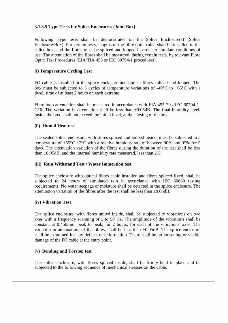
3.1.3.5 Type Tests for Splice Enclosures (Joint Box)
Following Type tests shall be demonstrated on the Splice Enclosure(s) (Splice Enclosure/Box). For certain tests, lengths of the fibre optic cable shall be installed in the splice box, and the fibres must be spliced and looped in order to simulate conditions of use. The attenuation of the fibres shall be measured, during certain tests, by relevant Fibre Optic Test Procedures (EIA/TIA 455 or IEC 60794-1 procedures).
(i) Temperature Cycling Test
FO cable is installed in the splice enclosure and optical fibres spliced and looped. The
box must be subjected to 5 cycles of temperature variations of -40C to +65C with a dwell time of at least 2 hours on each extreme.
Fibre loop attenuation shall be measured in accordance with EIA 455-20 / IEC 60794-1-C10. The variation in attenuation shall be less than ±0.05dB. The final humidity level, inside the box, shall not exceed the initial level, at the closing of the box.
(ii) Humid Heat test
The sealed splice enclosure, with fibres spliced and looped inside, must be subjected to a
temperature of +55C ±2C with a relative humidity rate of between 90% and 95% for 5 days. The attenuation variation of the fibres during the duration of the test shall be less than ±0.05dB, and the internal humidity rate measured, less than 2%.
(iii) Rain Withstand Test / Water Immersion test
The splice enclosure with optical fibres cable installed and fibres spliced fixed, shall be subjected to 24 hours of simulated rain in accordance with IEC 60060 testing requirements. No water seepage or moisture shall be detected in the splice enclosure. The attenuation variation of the fibres after the test shall be less than ±0.05dB.
(iv) Vibration Test
The splice enclosure, with fibres united inside, shall be subjected to vibrations on two axes with a frequency scanning of 5 to 50 Hz. The amplitude of the vibrations shall be constant at 0.450mm, peak to peak, for 2 hours, for each of the vibrations' axes. The variation in attenuation, of the fibres, shall be less than ±0.05dB. The splice enclosure shall be examined for any defects or deformation. There shall be no loosening or visible damage of the FO cable at the entry point.
(v) Bending and Torsion test
The splice enclosure, with fibres spliced inside, shall be firmly held in place and be subjected to the following sequence of mechanical stresses on the cable:
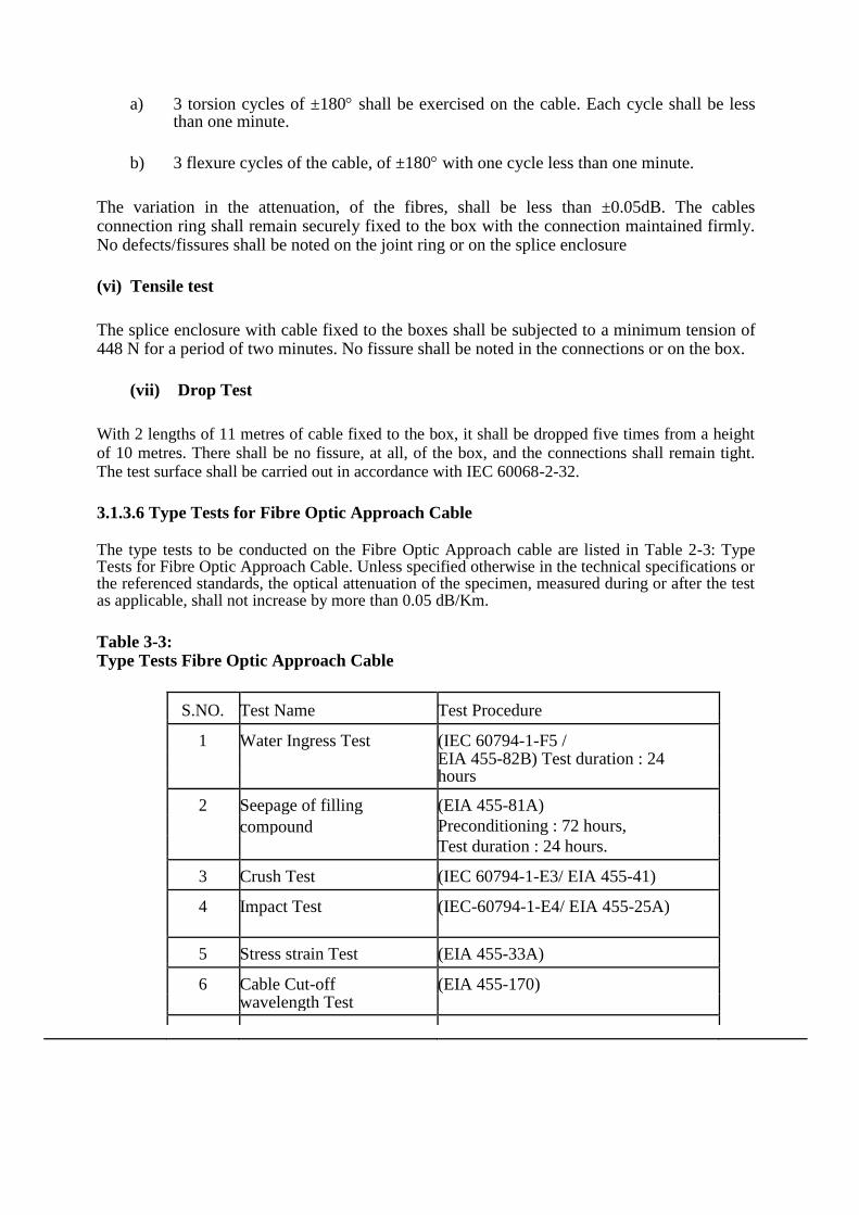
a) 3 torsion cycles of ±180 shall be exercised on the cable. Each cycle shall be less than one minute.
b) 3 flexure cycles of the cable, of ±180 with one cycle less than one minute.
The variation in the attenuation, of the fibres, shall be less than ±0.05dB. The cables connection ring shall remain securely fixed to the box with the connection maintained firmly. No defects/fissures shall be noted on the joint ring or on the splice enclosure
(vi) Tensile test
The splice enclosure with cable fixed to the boxes shall be subjected to a minimum tension of 448 N for a period of two minutes. No fissure shall be noted in the connections or on the box.
(vii) Drop Test
With 2 lengths of 11 metres of cable fixed to the box, it shall be dropped five times from a height of 10 metres. There shall be no fissure, at all, of the box, and the connections shall remain tight. The test surface shall be carried out in accordance with IEC 60068-2-32.
3.1.3.6 Type Tests for Fibre Optic Approach Cable
The type tests to be conducted on the Fibre Optic Approach cable are listed in Table 2-3: Type Tests for Fibre Optic Approach Cable. Unless specified otherwise in the technical specifications or the referenced standards, the optical attenuation of the specimen, measured during or after the test as applicable, shall not increase by more than 0.05 dB/Km.
Table 3-3: Type Tests Fibre Optic Approach Cable
S.NO. Test Name Test Procedure
1 Water Ingress Test (IEC 60794-1-F5 / EIA 455-82B) Test duration : 24
hours
2 Seepage of filling (EIA 455-81A)
compound Preconditioning : 72 hours,
Test duration : 24 hours.
3 Crush Test (IEC 60794-1-E3/ EIA 455-41)
4 Impact Test (IEC-60794-1-E4/ EIA 455-25A)
5 Stress strain Test (EIA 455-33A)
6 Cable Cut-off (EIA 455-170) wavelength Test

Table 3-3: Type Tests Fibre Optic Approach Cable
S.NO. Test Name Test Procedure
7 Temperature Cycling (IEC60794-1-F1/EIA-455-3A) – 2 Test cycles
-End Of Table-
3.1.3.6.1 Impact Test
The Impact test shall be carried out in accordance with IEC:60794-1-E4. Five separate impacts of 2.0 kg shall be applied at different locations. The radius of the intermediate piece shall be the reel drum radius ± 10%. A permanent or temporary increase in optical attenuation value greater than 0.05 dB/km shall constitute failure. 3.2 Factory Acceptance Tests Factory acceptance tests shall be conducted on randomly selected final assemblies of all equipment to be supplied. Factory acceptance testing shall be carried out on OPGW Cable and associated hardware & fittings, Approach Cable, Joint Box, FODP etc. and all other items for which price has been identified separately in the Bid Price Schedules. Material shall not be shipped to the Employer until required factory tests are completed
satisfactorily, all variances are resolved, full test documentation has been delivered to the
Employer, and the Employer has issued Material Inspection & Clearance Certificate
(MICC). Successful completion of the factory tests and the Employer approval to ship,
shall in no way constitute final acceptance of the system or any portion thereof. These
tests shall be carried out in the presence of the Employer's authorised representatives
unless waiver for witnessing by Employer’s representatives is intimated to the contractor.
Factory acceptance tests shall not proceed without the prior delivery to and approval of all test documentation by the Employer.
The factory acceptance tests for the supplied items shall be proposed by the Contractor in accordance with technical specifications and Contractor's (including Sub-Contractor's / supplier's) standard FAT testing program. In general the FAT for other items shall include at least: Physical verification, demonstration of technical characteristics, various operational modes, functional interfaces etc.
For Test equipment FAT shall include supply of proper calibration certificates, demonstration of satisfactory performance, evidence of correct equipment configuration and manufacturer’s final inspection certificate/ report.

3.2.1 Sampling for FAT
From each batch of equipment presented by the Contractor for Factory acceptance testing,
the Employer shall select random sample(s) to be tested for acceptance. Unless otherwise
agreed, all required FAT tests in the approved FAT procedures, shall be performed on all
samples. The Sampling rate for the Factory acceptance tests shall be minimum 10% of the
batch size (minimum 1) for all items. The physical verification shall be carried out on
100% of the offered quantities as per the approved FAT procedure. In case any of the
selected samples fail, the failed sample is rejected and additional 20% samples shall be
selected randomly and tested. In case any sample from the additional 20% also fails the
entire batch may be rejected.
For the OPGW cable hardware fittings & accessories, the minimum sampling rate, and batch acceptance criteria shall be as defined in IS 2486.
The Sampling rate for the Factory acceptance tests shall be 10% of the batch size (minimum 2) for FO cable drums, FODPs, Joint box and other similar items.
Since FAT testing provides a measure of assurance that the Quality Control objectives are being met during all phases of production, the Employer reserves the right to require the Contractor to investigate and report on the cause of FAT failures and to suspend further testing/ approvals until such a report is made and remedial actions taken, as applicable.
3.2.2 Production Testing
Production testing shall mean those tests which are to be carried out during the process of production by the Contractor to ensure the desired quality of end product to be supplied by him. The production tests to be carried out at each stage of production shall be based on the Contractor’s standard quality assurance procedures. The production tests to be carried out shall be listed in the Manufacturing Quality Plan (MQP), alongwith information such as sampling frequency, applicable standards, acceptance criteria etc.
The production tests would normally not be witnessed by the Employer. However, the Employer reserves the right to do so or inspect the production testing records in accordance with Inspection rights specified for this contract.
3.2.3 Factory Acceptance Tests on Optical Fibre to be supplied with OPGW
The factory acceptance tests listed in table below are applicable for the Optical fibres to be supplied. The listed tests follow testing requirements set forth in IEEE standard 1138/IEC 60794. The referenced sections specify the detailed test description. The acceptance norm shall be as specified in the above mentioned IEEE standards unless specified otherwise in the technical specifications.

Table 3-4 Factory Acceptance Tests for Optical Fibres: Optical Tests
S. No. Test Name Acceptance Criteria Test procedure
1 Attenuation Coefficient T S,Table 1-1(a) EIA/TIA 455- 78A
2 Point Discontinuities of TS, Section 1.1.2 EIA/TIA 455-59 attenuation
3 Attenuation at Water Peak TS ,Table 2-1(a) EIA/TIA 455- 78A
4 Chromatic Dispersion EIA/TIA 455- 168A/169A/175A
5 Core – Clad Concentricity Error EIA/TIA 455-/176
6 Cladding diameter EIA/TIA 455-176
7 Fibre Tensile Proof Testing EIA/TIA 455-31B
-End of table-
The test report for the above tests for the fibers carried out by the Fiber Manufacturer and used in the OPGW cables shall be shown to the inspector during OPGW cable FAT and shall be submitted along with the OPGW cable FAT report.
3.2.4 Factory Acceptance Test on OPGW Cable
The factory acceptance tests for OPGW cable specified below in Table follow the requirements set forth in IEEE standard 1138 / IEC 60794. The FAT shall be carried out on 10% of offered drums in each lot as specified in technical specifications and the optical tests shall be carried out in all fibres of the selected sample drums. The Rated Tensile Strength test shall be carried out on one sample in each lot.
Table 3-5 Factory Acceptance Tests on OPGW
Applicable standard: IEEE 1138 / IEC 60794
S. Factory Acceptance Test on Manufactured OPGW No.
1 Attenuation Co-efficient at 1310 nm and 1550 nm
2 Point discontinuities of attenuation
3 Visual Material verification and dimensional checks as per approved DRS/Drawings
4 Rated Tensile Strength
5 Lay Length Measurements

3.2.5 Factory Acceptance Test on OPGW Fittings
The factory acceptance tests for OPGW Fittings as specified below in Table 2-6. The sampling plan shall be as per relevant standard: Table 3-6 Factory Acceptance Tests On OPGW Fittings
S. No. Factory Acceptance Test Suspension Assembly
1 UTS/Mechanical Strength of the assembly
2 Clamp Slip Test
3 Visual Material verification and dimensional checks as per approved DRS/Drawings
4 Mechanical strength of each component
5 Galvanising test Tension Assembly
6 Clamp Slip Strength test
7 Visual Material verification and dimensional checks as per approved DRS/Drawings
8 Mechanical strength of each component
Galvanising Test Vibration Damper
10 Galvanising test on damper, masses and messenger wires
11 Damper response (resonant frequencies)
12 Clamp Slip test
13 Strength of messenger wires
14 Attachments of weights to messenger cable 15
Attachments of clamps to messenger cable 16 Clamp bolt tightening test 17 Clamp bolt torque test 18 Dynamic characteristic test.
19 Visual Material verification and dimensional checks as per approved DRS/Drawings
Structure Mounting Clamp

Table 3-6 Factory Acceptance Tests On OPGW Fittings S. No. Factory Acceptance Test
20 Clamp fit test
21 Clamp Strength test
22 Visual Material verification and dimensional checks as per approved DRS/Drawings End of Table
3.2.6 Factory Acceptance Test on Approach Cable The factory acceptance tests for Approach Cable specified below in Table 2-7:
Table 3-7
Factory Acceptance Tests On Approach Cable
S. No. Factory Acceptance Test
1 Attenuation Co-efficient at 1310 nm and 1550 nm
2 Point discontinuities of attenuation
3 Visual Material verification and dimensional checks as per approved DRS/Drawings
3.2.7 Factory Acceptance Test on Splice Enclosure (Joint Box) /FODP
The factory acceptance tests for Splice Enclosures/FODP as specified below in Table: 2-8 Table 3-8 Factory Acceptance Tests on Splice Enclosures (Joint Box)/FODP S. No. Factory Acceptance Test
1 Visual check of Quantities and Specific Component Number for each component of Splice Enclosure/FODP and dimensional checks against the approved drawings.
3.2.8 Factory Acceptance Test on Test Equipment & other items
As per technical specification and approved DRS/Documents.

3.3 Site Acceptance Tests The Contractor shall be responsible for the submission of all material & test equipment supplied in this contract for site tests and inspection as required by the Employer. All equipment shall be tested on site under the conditions in which it will normally operate. The tests shall be exhaustive and shall demonstrate that the overall performance of the contract works satisfies every requirement specified. At a minimum Site Acceptance Testing requirement for FO cable etc. is outlined in following section. This testing shall be supplemented by the Contractor's standard installation testing program, which shall be in accordance with his quality plan(s) for FO installation. During the course of installation, the Employer shall have full access for inspection and verification of the progress of the work and for checking workmanship and accuracy, as may be required. On completion of the work prior to commissioning, all equipment shall be tested to the satisfaction of the Employer to demonstrate that it is entirely suitable for commercial operation. 3.3.1 Minimum Site Acceptance Testing Requirement for FO Cabling
Prior to installation, every spooled fibre optic cable segment shall be tested for compliance with the Pre-shipment data previously received from the manufacturer. This requirement will preclude the installation of out of specification cable segments that may have been damaged during shipment.
3.3.1.1 Phases of Site Acceptance Testing SAT shall be carried out link by link from FODP to FODP. SAT may be performed in parts in case of long links.
The tests, checks, adjustments etc conducted by the Contractor prior to offering the equipment for SAT shall be called Pre-SAT activities. The Pre-SAT activities shall be described in the installation manuals and Field Quality Plan documents.
Sag and tension of OPGW shall generally be as per approved sag-tension chart and during installation, sag and tension of OPGW shall be documented. Upon completion of a continuous cable path, all fibres within the cable path shall be demonstrated for acceptance of the cable path. Fibre Optic cable site testing minimum requirements are provided in Table 2-9(a) through 2-9(c) below:

E-27- TS OPGW OPGW CABLE & Optic Fibre Equipment
Table 3-9(a)
Fibre Optic Cable Pre-Installation Testing
Item: Description:
1. Physical Inspection of the cable assembly for damage
2. Optical fibre continuity and fibre attenuation with OTDR at 1550 nm
3. Fibre Optic Cable length measurement using OTDR
Table 3-9(b)
Fibre Optic Cable Splicing Testing
Item: Description:
1. Per splice bi-directional average attenuation with OTDR
2. Physical inspection of splice box/enclosure for proper fibre / cable routing techniques
3. Physical inspection of sealing techniques, weatherproofing, etc.
Table 3-9(c)
Fibre Optic Cable Commissioning Testing
Item: Description:
1. End to End (FODP to FODP) bi-directional average attenuation of each fibre at
1310 nm and 1550 nm by OTDR.
2. End to End (FODP to FODP) bi-directional average attenuation of each fibre at
1310 nm and 1550 nm by Power meter.
3. Bi-directional average splice loss by OTDR of each splice as well as for all
splices in the link (including at FODP also).
4. Proper termination and labelling of fibres & fibre optic cables at FODP as per
approved labelling plan.
-End of Table-

E-27- TS OPGW OPGW CABLE & Optic Fibre Equipment
GUARANTEED TECHNICAL PARTICULARS OF OPGW CABLE & HARDWARE
ACCESSORIES
Sl.No. Description. Technical Particulars
1. Make & Model
2. No. of Fibres in OPGW 24
3. Mode DW-SM
4. Buffer type Loose
5. Buffer tube diameter 2.2mm
6. Buffer tube material PBT
7. No. of buffer tubes 4
8. No. of fibres per tube 6
9. Identification/numbering of individual tubes
Red, green blue and natural.
10. No.of empty tubes (if any) 1
11. Filling material Moisture proof & Hydrogen adherent jelly.
12. Strength members 1
13. Binding yarn/tape Tapes
14. (i)10% Aluminium clad steel wire (ii)20.3% IACS
(i) 2.25mm (Dia) & 12 Nos. (ii) 2.6 mm (Dia) & 11 Nos. (iii) Other design meeting to the electrical & mechanical parameters as per detail technical specification.
15. Aluminium alloy wires (Diameter & Number)
2.25mm & 3 Nos.
16. Aluminium tube diameter Design dimensional parameters of OPGW should meet the SAG-Tension criteria as enclosed at Appendix-A
17. Approximate outside diameter
18. Cable diameter
19. Cable cross section area
20. Min. Breaking load/ Ultimate Tensile Strength
82.10kN
21. Fibre Strain margin 0.6%
22. Weight Kgs/Km 488 kgs/km
23 Crush strength 1000kg with a 10cm2 piste
24. Modulus of Elasticity 135.8kN/mm2
25. Minimum bending radius 300mm
26. Maximum bending radius Short term 300mm Long term 400mm
27. Maximum permissible tensile stress -
28. Permissible CTS Tensile stress 0.669kN/- mm2
29. Coefficient of inner expansion 15.3 X 10⁻⁶ per 0C
30 Coefficient expansion Cladding Core 6.3 X 10⁻⁶ per 0C
31 Nominal operating temperature range -10 0C to 70 0C
32 SC current transient peak temperature
41 KA
33 Maximum allowable temperature for lightning strike
200
34 Available length of cable per drum:

E-27- TS OPGW OPGW CABLE & Optic Fibre Equipment
Min Max
2500 mtrs 3500 mtrs or as per site requirement.
35 Splice loss (Min. & Max. Allowable)
0.05 dB. 0.01 dB
36 Operating Temperature range- -10 0C to 70 0C
37 Expected Cable Life 25 years.
38. Fibre production method -
39. Core diameter. 9.2 +/-0.5 µm
40 Core non circularity -
41. Cladding diameter 125+/-0.5 µm
42 Core Clad Concentricity Error < 1 µm
43 Cladding non circularity < 2%
44 Protective coating type & material Primary Secondary.
Acrylate PBT
45 Protective coating Diameter -
46 Coating concentricity >70%
47 Colour Coding scheme compliant with EIA 395/IEC3047
48 Attenuation Coefficient @ 1310nm – @1559nm-
.36 dB/km .22 dB/km
50 Mode field non Circularity < 2%
51 Romatic Dispersion 1310 nm 1550 nm
2.8 ps/ (n.km) 18 ps/(nm.km)
E-27- TS OPGW OPGW CABLE & Optic Fibre Equipment
3.TECHNICAL SPECIFICATION
OPTIC FIBRE EQUIPMENT AND NETWORK CONFIGURATION
Introduction General Network Characteristics 3.2.1 Description
3.2.2 Functional Requirement 3.2.3 General Systems Requirements System Synchronisation System maintainability System Upgradability and Expandability
Equipment Availability General Equipment Characteristics
Revision Levels and Modifications
Equipment Capacities
Redundancy Requirements & Protection Scheme
Lost Signal Recovery
Equipment Lifespan
General Site Considerations
Fibre Optic Link Lengths
Fibre Optic Transmission System
3.3.1 SDH Equipment
3.3.1.1 Functional Requirement
3.3.1.2 Redundancy and Protection
3.3.1.3 Service Channel

E-27- TS OPGW OPGW CABLE & Optic Fibre Equipment
3.3.1.4 Supervision and Alarms 3.3.1.5 Synchronisation 3.3.1.6 Electrical and Optical I/O Characteristics and General Parameters 3.3.2 Optical Link Performance Requirements 3.3.2.1 Link Budget Calculations
Link Performance
3.3.2.3 FODP to SDH Equipment
3.4 Termination Equipment Subsystem Functional Description First Order (Primary) Multiplexing Drop & Insert Primary Multiplexing Channel Banks (Mux, Drop/Insert)
3.4.5.3 Subscriber Line Units\Subscriber Line Interface Cards Digital Access Cross connect System Required DACS Applications Menus and Reports MDF, DDF and Cabling 3.5.1 MDF and DDF Patching Facilities 3.5.1.1 Digital Distribution Frame Functional Requirements 3.5.1.2 Main Distribution Frames 3.6 Patch Cords 3.7 Telecommunication Management Network / Network Management System 2.7.1 Performance Management 3.8 Communication Channel Requirement and Integration

E-27- TS OPGW OPGW CABLE & Optic Fibre Equipment
3.9 Craft Terminal
3.9.1 Hardware Requirement 3.10 General Software/Firmware Requirements 3.10.1 Operating System Software 3.10.2 Applications Software 3.10.3 Software Utilities 3.10.4 Revisions, Upgrades, Maintainability 3.10.5 Help
E-27- TS OPGW OPGW CABLE & Optic Fibre Equipment
OPTIC FIBRE EQUIPMENT AND NETWORK CONFIGURATION Introduction
This section describes the Fibre Optic Communication network configuration and the
equipment characteristics for communication system to be installed under the
project. The sub-systems addressed within this section are:
(1) Fibre Optic Transmission System (FOTS)
Termination Equipment Subsystems Network Management System (NMS) MDF, DDF and Cabling
The requirements described herein are applicable to and in support of network
configurations depicted in Annexure-II and Network Management System (NMS) for
monitoring and control of this communication network. TMN and NMS have been
interchangeably used in this specification.
General Network Characteristics
Description
The proposed fibre optic communication network shall support the voice & data
communication requirements of RTUs and the SCADA/EMS system. The
communication system shall provide data & voice connectivity across the various
locations or connectivity of RTUs with Control Centres. The RTUs located at various
locations will report to Control Center using IEC 60870-5-101 or IEC 60870-5-104
Protocol. The proposed communication system shall provide connectivity of some
RTUs over TCP/IP protocol using Ethernet interface and other RTUs over serial
interface.
The fibre optic network shall be based on Synchronous Digital Hierarchy (SDH) i.e.
STM-4. However, the offered equipment can be upgraded to STM-16 by changing
the optical card only. The Contractor can propose a system based on higher bit rate
systems, if required, so as to meet the link budget requirements or any other
specification requirement. The detailed BOQ is described in Annexure-V(A-C).

E-27- TS OPGW OPGW CABLE & Optic Fibre Equipment
Functional Requirement
The primary function of the communication network is to provide a highly reliable voice
and data communication system in support of the SCADA/EMS. The communications
support requirement for SCADA/EMS system is for low & high speed data, express voice
circuits and administrative voice circuits as defined in appendices. A brief summary of the
communication system requirements is as follows:
(a) High speed E1 channel support
(b) 64kbps & nx64kbps data channel support
(c) Low speed (300 -1200 bps) data channel support
(d) Voice (2 wires, 4 wires) channel support.
(e) Data transport supporting Network Management channels
The connectivity envisaged between RTUs and Control Centre is Wide Area Network (WAN) on TCP-IP using IEC 60870-5-104 protocol and IEC 60870-5-101 protocol.
General Systems Requirements
Required characteristics are defined and specified herein at the system level,
subsystem level, and equipment level.
3.2.3.1 System Synchronization
The Contractor shall synchonize all the equipments under the contract using Master
clock (PRC). The Contractor shall provide the GPS based clock. In addition to GPS
input reference, the synchronization clock must have provision to take INPUT
reference coming from other clock. The contractor shall submit the synchronisation
plan as per standard ITU-T G.811. All sync equipments proposed under this contract
should meet ITU-T G.811 criterion. The holdover quality of clock shall meet ITU-T
G.812 standard requirements.
The Contractor shall provide system wide synchronization fully distributed throughout
the telecom network and connected to all equipments. The Contractor shall submit
the synchronization plan for the entire network meeting the requirement of ITU-T
G.803.
E-27- TS OPGW OPGW CABLE & Optic Fibre Equipment
The system equipment requiring “clock” shall be connected to the master clock using
external clocking. For this purpose, appropriate interfaces(s) in the transmission &
termination equipment being supplied and all other associated hardware shall be
provided by the Contractor.
3.2.3.2 System Maintainability
To facilitate performance trending, efficient diagnosis and corrective resolution, the
system shall permit in-service diagnostic testing to be executed both locally and from
remote locations, manually and/or initiated under TMN control. Such testing shall not
affect the functional operation of the system.
Preventive and problem oriented maintenance of the communications system shall
be performed using diagnostics tools such as TMN and test equipment. They shall
support complete maintenance of all system elements and shall permit the diagnosis
of any fault without requiring additional test equipment. The Contractor shall provide
specialized training required to operate above mentioned diagnostic tools. For all
redundant systems, disconnection and repair of any failed device shall not interrupt
the operation of the system.
3.2.3.3 System Upgradeability and Expandability
Equipment supplied shall be sized (though not necessarily equipped) to support
system/ subsystem expansion to full capacity as provided by specified aggregate
transmission rates. Equipment units provisioned for equipped subunits shall be
terminated at appropriate patching facilities or termination blocks. Power supplies
and TMN shall be sized for maximum equipped system capacity.
3.2.3.4 Equipment Availability
The availability requirements are as follows, which shall be demonstrated at site for
the equipments being provided under this contract:
The availability of each fibre optic link (E1 to E1) shall be at least 99.999%. The availability of network end to end (E1 to E1) shall be at least 99.998%. (3) The average per link subscriber to subscriber availability shall be at least 99.97%. The per link subscriber to subscriber availability is defined as the availability between any two data or voice subscribers between RTU to reporting Control Centre. (4) The network-wide subscriber to subscriber availability shall be atleast 99.8% .The network-wide subscriber to subscriber availability is defined as the availability between any two data or voice subscribers on the wideband network.
The calculated availability is defined as the theoretical availability determined by a
statistical calculation based on the mean-time-between-failure (MTBF) and the
mean-time-to-repair (MTTR) of the components and subsystems comprising the
E-27- TS OPGW OPGW CABLE & Optic Fibre Equipment
FOTS. The down time of the fibre optic cable shall not be considered in the aforesaid
availability calculations.
In order to ensure that the equipment & configuration proposed by the bidders shall
be capable of demonstrating the specified availability figures it is required that the
Bidders shall include in their proposal a calculated availability analysis for the
proposed equipment/ sub system. The calculated failure rates of the units and the
calculated availabilities of the equipment being offered shall be provided in the
proposal. The analysis shall be based on an availability block diagram and shall
include the mean-time-between failure (MTBF) and mean-time-to-repair (MTTR) of
all of the components on the link. The Contractor shall indicate in the analysis the
MTBF and MTTR and the resulting availability of each point-to-point link. For this
analysis, an MTTR of at least 4 hours shall be assumed.
3.2.4 General Equipment Characteristics
All Contractor supplied equipment shall be new and of the finest production quality.
OPTCL will not accept modules or printed-circuit boards that are modified by
appending wires or components. Wired strapping options shall be incorporated in the
board design to meet the above requirement.
All applicable requirements stated in this section shall equally apply to the TMN
equipment as specified in this Section.
3.2.4.1 Revision Levels and Modifications
All hardware, firmware and software delivered as part of the communications
network shall be field proven and at the most of current revision level. All
modifications and changes necessary to meet this requirement shall be completed
prior to the start of the factory tests or under special circumstances, on written
approval by OPTCL, prior to the completion of SAT.
All field modifications of the hardware, firmware and software that is required to meet
installation and/or performance specifications, shall be fully documented as part of
the deliverables, both as a separate field modifications record and as corrected
equipment/configuration documentation.
3.2.4.2 Equipment Capacities
Equipment supplied shall be sized and equipped with sufficient capacity to support
BoQ and configuration requirements as identified in the Annexure-3(A-B) . Each
subsystem supplied shall be sized (to be equipped as specified) to support full
subsystem expansion.

E-27- TS OPGW OPGW CABLE & Optic Fibre Equipment
Data communications channelization required to support the TMN subsystems
specified in Technical Specifications (TS) are not identified in the appendices.
Therefore, the Contractor is required to size and equip the system to include all
channelization and channel cards required to support the TMN function.
3.2.4.3 Redundancy Requirements and Protection Schemes
Equipment redundancy and Automatic Protection Schemes (APS) are specified in
the Table 2-1. The failure of one element shall not prevent the use of any other that
has not failed.

E-27- TS OPGW OPGW CABLE & Optic Fibre Equipment
Table 2-1
Equipment Redundancy Requirements Summary
Fiber Optic transmission Equipment :
SDH equipment
Power Supply & Converters ----------------------------
--
Common Control* Cards --------------------------------
---
DACS (Cross Connect)
Power Supply ------------------------------------------------
--
Common control* cards----------------------------------
---
MUX, DROP/INSERT
Power Supply ------------------------------------------------
---
* = Common control cards which are essentially
required for operation of the equipment.
1:1 APS or distributed power
supply
1:1 APS
1:1 APS or distributed power
supply
1:1 APS
1:1 APS or distributed power
supply
E-27- TS OPGW OPGW CABLE & Optic Fibre Equipment
The offered equipment shall support at least SNCP as per standard ITU-T G.841. In
case the equipment offered by the Bidder does not support the above mentioned
minimum protection methods, the bidder shall have to provide all additional
equipment needed to provide same level of flexibility, redundancy and functionality at
no additional cost to OPTCL. The bidders shall provide details of protection schemes
supported in the Bid document.
The offered equipment shall support automatic switchover function between the
redundant modules and all required modules and hardware to support the automatic
switch over shall be provided by the Contractor.
3.2.4.4 Lost Signal Recovery
At any digital signal level, reapplication of a lost signal shall result in automatic
resynchronization and full restoration to normal operation without manual
intervention. All alarms incident to the signal failure, shall be automatically cleared at
the equipment, rack and monitoring levels and normal operation indications restored
and reported if applicable.
3.2.4.5 Equipment Lifespan
All equipment supplied shall have a minimum expected life of fifteen (15) years. from
the date of operational acceptance.
3.2.4.6 General Site Considerations
All fiber optic links up to 250 kms transmission line route length shall be implemented
by the Contractor without repeaters. In order to meet the link budget requirement, the
Contractor shall provide all the necessary equipment only in the end stations. The
contractor may provide the optical amplifier, wave length translator, optical cards or
high capacity SDH equipment with suitable rack/sub-rack to meet the maximum
distance limit. All the provided equipment shall be monitored by centralized NMS
which is already in operation at SLDC.
3.2.5 Fibre Optic Link Lengths
The fiber optic route lengths are as specified in Annexure- IA & IB. The lengths
specified in appendices are the transmission line route lengths; however the actual
fiber cable length shall exceed the route lengths on account of extra cable
E-27- TS OPGW OPGW CABLE & Optic Fibre Equipment
requirement due to upcoming LILO sub-stations , sag, jointing & splicing, approach
cabling etc. For bidding purposes the Contractor may assume an additional cable
length of 5% of given route length + 1Km towards approach cable for calculating the
link length. The exact cable lengths shall be determined by the Fibre Optic cable
package Contractor during the survey. The same shall be forwarded to this package
Contractor for final link design during the detailed engineering of the project. In case
of change in the specified BoQ, the contract price shall be adjusted accordingly.
Fibre Optic Transmission System
The Fibre Optic Transmission System (FOTS) is defined herein to include ETSI
digital optical line termination equipment. The FOTS shall be based on SDH
technology. Minimum aggregate bit rate shall be STM-4 and equipped with minimum
2 nos. of 16 port E1 interface(G.703) card & one no. of minimum 4 port Ethernet
interface (IEEE 802.3/IEEE 802.3u) card supporting layer 2 switching as tributaries.
The Ethernet interfaces shall support VLAN (IEEE 802.1P/Q), spanning tree (IEEE
802.1D) quality of service.
The Contractor shall provide (supply and install) connectorised jumpers (patch
cords) for FODP-to-equipment and equipment-to-equipment connection. Two
number spare jumpers shall be provided for each equipment connection. Fiber
jumpers shall be of sufficient lengths as to provide at least 0.5m of service loop when
connected for their intended purpose.
3.3.1 SDH Equipment
2.3.1.1Functional Requirement
The BOQ is provided in the Annexure-V(A) & Annexure-V(B). For the purpose of
BOQ, the SDH Equipment is considered to be divided in three parts i.e. Optical cards
(Line), Tributary Cards ( Electrical tributaries such as E1 & Ethernet 10/100 Mbps)
and Base Equipment (Consisting of Common Cards, Power supply cards, sub-rack,
cabinet, other hardware and accessories required for installation of equipment i.e.
everything besides optical cards and tributary cards).
The offered SDH equipment shall be upgradeable to STM-16 by changing optical
line cards only. Cross connection (VC4) capability of offered SDH equipment shall be
provided according to STM-4 equipment. The contractor shall demonstrate the STM
4 to STM 16 upgradeability during FAT.
SDH ADM
The aggregate interfaces shall be (at least) STM-4 (622 Mbit/s) towards at least 3
directions (Protected as specified in this specifications). At present the equipment
shall be equipped with a 2 nos., min.16 E-1 port electrical tributary cards & one no.,
min.4 port Ethernet interface card as tributaries. The Equipment shall provide access
to full STM4 payload.
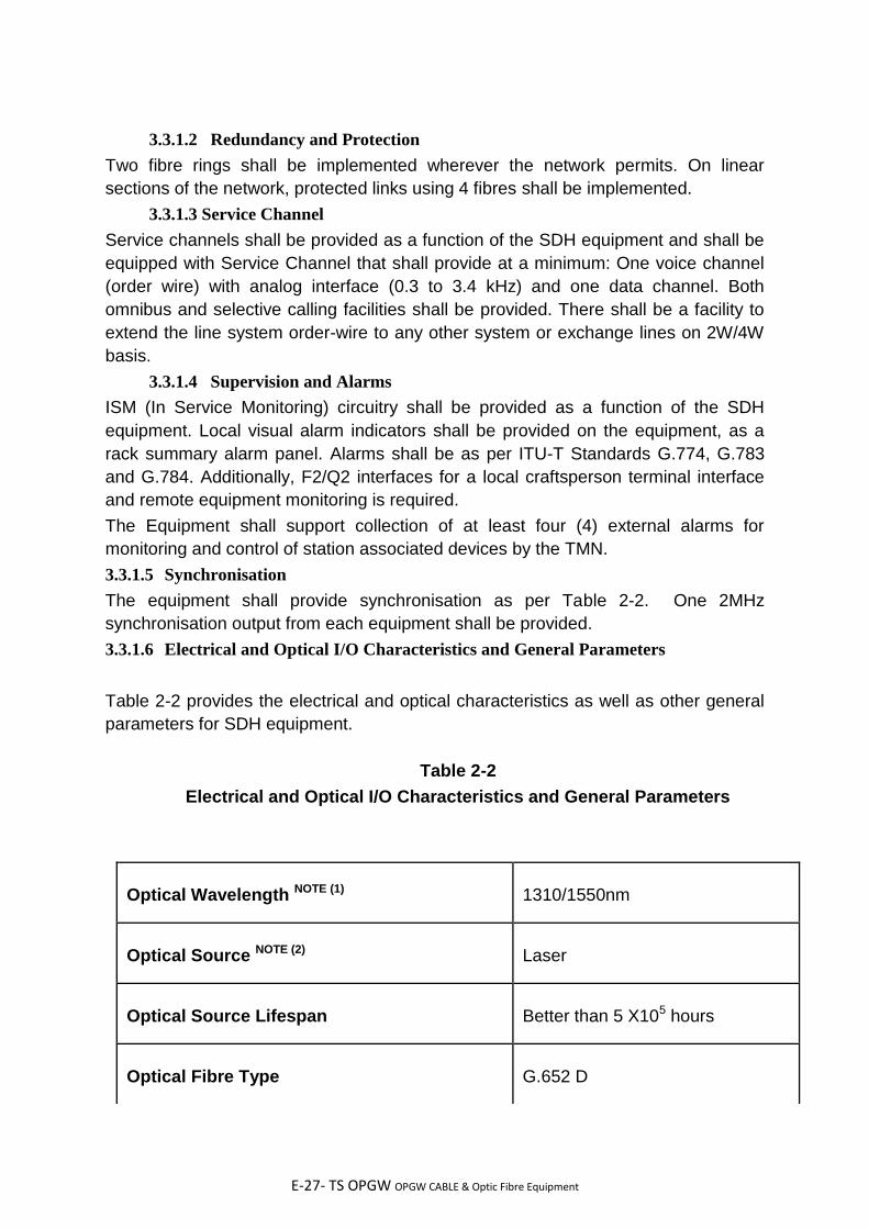
E-27- TS OPGW OPGW CABLE & Optic Fibre Equipment
3.3.1.2 Redundancy and Protection
Two fibre rings shall be implemented wherever the network permits. On linear
sections of the network, protected links using 4 fibres shall be implemented.
3.3.1.3 Service Channel
Service channels shall be provided as a function of the SDH equipment and shall be
equipped with Service Channel that shall provide at a minimum: One voice channel
(order wire) with analog interface (0.3 to 3.4 kHz) and one data channel. Both
omnibus and selective calling facilities shall be provided. There shall be a facility to
extend the line system order-wire to any other system or exchange lines on 2W/4W
basis.
3.3.1.4 Supervision and Alarms
ISM (In Service Monitoring) circuitry shall be provided as a function of the SDH
equipment. Local visual alarm indicators shall be provided on the equipment, as a
rack summary alarm panel. Alarms shall be as per ITU-T Standards G.774, G.783
and G.784. Additionally, F2/Q2 interfaces for a local craftsperson terminal interface
and remote equipment monitoring is required.
The Equipment shall support collection of at least four (4) external alarms for
monitoring and control of station associated devices by the TMN.
3.3.1.5 Synchronisation
The equipment shall provide synchronisation as per Table 2-2. One 2MHz
synchronisation output from each equipment shall be provided.
3.3.1.6 Electrical and Optical I/O Characteristics and General Parameters
Table 2-2 provides the electrical and optical characteristics as well as other general
parameters for SDH equipment.
Table 2-2
Electrical and Optical I/O Characteristics and General Parameters
Optical Wavelength NOTE (1)
1310/1550nm
Optical Source NOTE (2)
Laser
Optical Source Lifespan
Better than 5 X10⁵ hours
Optical Fibre Type
G.652 D
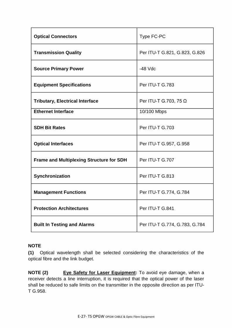
E-27- TS OPGW OPGW CABLE & Optic Fibre Equipment
NOTE
(1) Optical wavelength shall be selected considering the characteristics of the
optical fibre and the link budget.
NOTE (2) Eye Safety for Laser Equipment: To avoid eye damage, when a
receiver detects a line interruption, it is required that the optical power of the laser
shall be reduced to safe limits on the transmitter in the opposite direction as per ITU-
T G.958.
Optical Connectors
Type FC-PC
Transmission Quality
Per ITU-T G.821, G.823, G.826
Source Primary Power
-48 Vdc
Equipment Specifications
Per ITU-T G.783
Tributary, Electrical Interface
Per ITU-T G.703, 75 Ω
Ethernet Interface 10/100 Mbps
SDH Bit Rates
Per ITU-T G.703
Optical Interfaces
Per ITU-T G.957, G.958
Frame and Multiplexing Structure for SDH
Per ITU-T G.707
Synchronization
Per ITU-T G.813
Management Functions
Per ITU-T G.774, G.784
Protection Architectures
Per ITU-T G.841
Built In Testing and Alarms
Per ITU-T G.774, G.783, G.784

E-27- TS OPGW OPGW CABLE & Optic Fibre Equipment
NOTE (3)In case other than FC-PC connector is provided in the equipment, suitable
patch cord with matching FC-PC connector are to be provided to connect with
FODP.
3.3.2 Optical Link Performance Requirements
The optical fibre link performance requirements are specified as follows:
3.3.2.1 Link Budget Calculations
The fibre optic link budget calculations shall be calculated based upon the following
criteria:
(1) Fibre attenuation: The fibre attenuation shall be taken to be the guaranteed
maximum fibre attenuation i.e. 0.21 dB/Km @1550nm and 0.35 dB/km
@1310nm.
(2) Splice loss: Minimum 0.05 dB per splice. One splice shall be considered for
every 3 kms.
(3) Connector losses: Losses due to connectors shall be considered to be
minimum 1.0 dB per link.
(4) Equipment Parameters: The equipment parameters to be considered for link
budget calculations shall be the guaranteed “End of Life (EOL)” parameters. In
case, the End of Life parameters are not specified for the SDH equipment, an
End of Life Margin of at least 2 dB shall be considered and a similar margin
shall be considered for optical amplifiers.
(5) Optical path Penalty: An optical path penalty of at least 1 dB shall be
considered to account for total degradations due to reflections, inter symbol
interference, mode partition noise and laser chirp.
(6) Maintenance Margin: A maintenance margin of at least 2.5 dB/100Km shall be
kept towards cabling, repair splicing, cable ageing and temperature variations
etc.
(7) Other losses: Other losses, if any required specifically for system to be supplied
shall also be suitably considered.
(8) Dispersion: The fibre dispersion shall be taken to be the guaranteed maximum
dispersion i.e. 18 ps/nm.Km @1550 nm & 3.5 ps/nm.km @ 1310 nm for DWSM
fibres.
(9) Bit Error Rate: The link budget calculations shall be done for a BER of 10-10.

E-27- TS OPGW OPGW CABLE & Optic Fibre Equipment
The bidders shall determine the total link loss based on the above parameters and
shall submit the system design (including link budget calculations) for each category
of fibre optic link in the Bid.
For finalising the FOTS system design & BOQ, above methodology shall be adopted
taking into account fibre attenuation, dispersion and splice loss determined during
the detailed engineering. Accordingly, additions and deletions from the contract shall
be carried out based on unit rates indicated in the contract.
3.3.2.2 Link Performance
The Link performance for ES, SES and BER for the fibre optic links shall correspond
to National Network as defined in ITU-T G.826.
3.3.2.3 FODP to SDH Equipment Optical Amplifier Connectivity
The Contractor shall be responsible for connectivity between the FODP and the SDH
equipment. The Contractor shall provide FC PC coupled patch cords. The location of
FODP shall be finalized during detailed engineering.
The patch-cord length between the FODP & equipment rack shall be suitably
protected from rodents, abrasion, crush or mechanical damage.
Termination Equipment Subsystem
The Termination Equipment Subsystem is defined to include the equipment that
interfaces (adapts) the subscriber (user) to the Fibre Optic Transmission System
(FOTS). A Functional description of these equipments are as follows:
3.4.1 Functional Description
The transmission network node provides subscriber interface to the transmission
network and/or switching/routing. For clarity, the basic functions accomplished at the
network nodal points, are described briefly as follows:
Primary Multiplexer shall be used to accomplish subscriber connectivity to the Digital
Communication Network. Subscriber Line Units shall provide analog to digital and
direct digital conversion to 64 Kbps digital channel. In the CEPT standard hierarchy,
thirty (30) such 64 Kbps digital channels shall be Time Division Multiplexed (TDM)
resulting in a single 2.048 Mbps (E-1) digital bit stream.
Digital Drop-Insert and Branching Equipment shall be used to digitally interface a
small number of channels at spur locations without requiring successive D/A and A/D
conversions of the throughput channels.
Digital Cross connect Equipment (DACS) shall be used to provide software
controlled dynamic routing/rerouting of the primary (E-1) bit stream as well as the 30
channels of the E1 bit stream.

E-27- TS OPGW OPGW CABLE & Optic Fibre Equipment
The equipment shall also have an interface for external 2048 kHz synchronisation
signal according to ITU-T Recommendation G.703.
3.4.2 First Order (Primary) Multiplexing
The Contractor shall be required to provide E-1 Drop & Insert Multiplexer and E-1
Channel Bank primary multiplexing in compliance with the electrical input-output
characteristics provided in Table 2-3.
3.4.2.1 Drop & Insert Primary Multiplexing
Drop & Insert primary multiplexing in conformance with CEPT E-1 characteristics
shall be required at locations where the subscriber requirement is minimal. The drop
and insertion of up to thirty 64 Kbps channels supporting subscriber line units (SLU)
shall be required at intermediate locations. The Drop & Insert Muxes supplied shall
be performance and card compatible with the Channel Bank Equipment provided so
that all Subscriber Line Interface cards are interchangeable.
Table 2-3
CEPT E-1 Standard First Order Multiplexing
Electrical Input/Output Characteristics
Applicable Standards:
CEPT per CCITT Recommendation G.702,
G.703, G.711 and G.712
Number of Tributaries:
30 X 64 Kbps
Alternative Sub-rate
Tributaries:
n X 64 Kbps V.36
64Kb/s V.11/V.36
Output Aggregate Rate:
Interface Code:
Impedance:
Peak Level @ 120 ohm:
Peak Level @ 75 ohm:
Maximum Insertion Loss:
2.048 Mb/s ± 50 ppm
HDB3
75 ohm unbalanced
3.0 volts ± 10%
2.37 volts ± 10%
6 db
Signal Waveform:
Frame Structure:
Jitter Performance:
Per CCITT G.703
Per CCITT G.742
Per CCITT G.823
E-27- TS OPGW OPGW CABLE & Optic Fibre Equipment
Table 2-3
CEPT E-1 Standard First Order Multiplexing
Electrical Input/Output Characteristics
Power Supply Voltage: -48 Vdc
3.4.2.2 Channel Banks (Mux, Drop/Insert)
User voice and data equipment interfacing requirements are defined at the
subscriber line level. Primary multiplexing in conformance with CEPT E-1
characteristics shall be used to provide first order multiplexing of up to thirty 64 Kbps
channels supporting Subscriber Line Units (SLUs).
3.4.2.3 Subscriber Line Units\Subscriber Line Interface Cards
The terms Subscriber Line Interface Cards and Subscriber Line Units have been
used interchangeably throughout the specification. Multiple configurations of SLUs
shall be required to provide subscriber to primary multiplexer Bank interfacing for a
variety of voice and data communications. In case there are changes in number or
type of cards because of changes in channel requirements, the contract price shall
be adjusted accordingly.
The SLU interface requirements are discussed in the following subparagraphs:
(A) Voice Channels
The voice channel requirement is for (I) 4-Wire E&M trunking in support of PABX
trunks & PLCC VF and (II) 2-Wire telephonic interfaces. 2 wire SLUs shall be
DTMF/TP optioned for 2-wire loop start or 2-wire GND start. The voice cards shall
utilize ITU.T A - law companded PCM G.711, 64 kbits/s encoding. The voice card
requirements are indicated in the BoQ in Annexure-III(A) & Annexure-III(B)
(B) Sub-Channel Data Multiplexing
For this Project, the RTU data interface to the wideband telecommunications network
node shall be defined at the DTE level at low-speed rates of 300, 600 and 1200
baud. The port shall be compatible with RS232C interface. The Contractor shall be
required to furnish 64 Kbps SLU asynchronous dataplexing for at least 4 selectable
low speed DTE interfaces whenever multiple asynchronous data circuits are
required.
(C) Synchronous Data
E-27- TS OPGW OPGW CABLE & Optic Fibre Equipment
The Contractor shall provide a direct DTE interface for synchronous communications
at speed of 64Kbps and compatible with CCITT G.703 Kbit/s, V.35 and X.21
interfaces. Data rate selection shall be switch selectable or programmable.
(D) Nx64 kbps Synchronous Data
There is also a requirement for N x 64 kbps V.35, X.21 interfaces. The tentative
quantities have been identified in the Annexure-III(A) & Annexure-III(B) .
However the final BOQ shall be worked out during detailed design and contract price
shall be adjusted accordingly.
3.4.3 Digital Access Cross connect System
The Contractor shall be required to provide Digital Access Cross connect Systems
(DACS) capable of switching 16 or more E-1 lines in compliance with the electrical
input-output characteristics provided in Table 2-4. DACSs shall be fully compatible
with CEPT E-1 tributary standards.
DACSs shall be provided at locations specified in the Annexure-II and shall be used
to establish and reconfigure cross-connections at the tributary level of up to 480 x
64Kb/s channels. DACS E-1 line interface shall be fully capable of accessing each
E-1 line.
Within the context of this specification, sizing of DACS system is defined as 4 x n
where n is the maximum size of the port switching matrix. Thus a DACS sized as 8 x
16 means that 8 E1 ports are interfaced over a 16 port (E1) matrix.
A DACS system shall consist of the switch matrix, all routing logic and timing
circuitry for internally sourced, line derived or externally supplied network timing and
full software support.
The DACSs to be provided under this contract shall consist of at least a 16 port
switching matrix, with 16 ports equipped, i.e. 16 X 16 size. The DACS shall also be
able to switch the signalling of the voice channels along with the voice channels. The
DACS shall not use, decrease or block the specified capacity of the switching matrix
while switching the signalling. The DACS shall support the Channel Associated
Signallling (CAS) and Common Channel Signalling (CCS) both as per ITU-T G. 704.
The DACS shall provide user friendly control and management software. The user
shall be able to operate the DACS locally through craft terminal, via an RS-232
interface or remotely under TMN supervisory control.

E-27- TS OPGW OPGW CABLE & Optic Fibre Equipment
Table 2-4
CEPT E-1 Digital Access Cross Connect System
Required Operating Characteristics
E-1 Trunk Capacity:
Minimum 16-Port Switch Matrix
Minimum 4-Port I/O per card
Tributary Capacity:
30 X 64 Kbps
Compatibility:
CEPT E-1, CEPT E-1 tributary channel
Frame Delay:
Minimum < 1 frame
Maximum < 2 frames
E-1 Port Interface:
Interface Code:
Impedance:
Peak Level @ 75 ohm:
Maximum Insertion Loss:
2.048 Mb/s ± 50 ppm
HDB3
75 ohm unbalanced
2.37 volts ± 10%
6 db
Signal Waveform:
Frame Structure:
Jitter Performance:
Per CCITT G.703
Per CCITT G.742
Per CCITT G.823
Synchronisation:
Internal, external source and synchronized on
incoming E-1
Routing:
Routing Table Capacity:
Fully non-blocking tributary to/from E-1 channel
Minimum of 9 routing tables for reconfiguration
Supervisory Ports:
Supervisory Port Interface:
Interface:
Serial Com Ports
RS-232
Standard ASCII ANSI compatible terminal
Supervisory Channel:
Async data rates, software selectable:
speed of 110-9600 bps, odd or even parity
7 or 8 bits.
E-27- TS OPGW OPGW CABLE & Optic Fibre Equipment
Table 2-4
CEPT E-1 Digital Access Cross Connect System
Required Operating Characteristics
Power Supply Voltage: -48 VDC
3.4.3.1 Required DACS Applications
The DACS provided shall be fully capable of implementing standard applications
such as "Groom and Fill", Drop & Insert/Bypass, Broadcast and Alternative Routing.
3.4.3.2 Menus and Reports
DACSs throughout the network shall be required to function as fully integrated
subsystems of the Telecommunications Management Network (TMN) commissioned
at SLDC..
The DACS software shall provide menu driven management of DACS and shall
provide at least the following:
(I) Active Configuration: The user shall be able to modify the current active
configuration.
(II) Configuration : The configurations other than the active one shall be listed,
edited, viewed, renamed, deleted and activated . Actions shall be allowed manually,
upon a carrier failure or specified alarm condition, remotely or on a scheduled basis.
(III) Reports : The user shall have selection of pre formatted specific reports and
"Report Options" to be used to select where the next reports will be sent.
(IV) Administration: This shall provide the user, options to control, view and
maintain various logs and the DACS software.
(V) Alarms: This shall display Alarm Status on all active ports and shall have an
alert mechanism that readily identifies an alarm event to the user through TMN
(locally as well as remotely). The alarms shall have different colours based on the
importance of the alarm.
3.5 MDF, DDF and Cabling
E-27- TS OPGW OPGW CABLE & Optic Fibre Equipment
For the purposes of the specification, the contractor shall provide cabling, wiring,
DDF patching facilities and MDFs interfacing to the wideband telecommunications
system. Equipment and material components for MDF, DDF and cabling are also
part of this procurement. It shall be the Contractor's responsibility to provide all cable
support required for full supplied equipment interconnection with the MDF and shall
be in accordance with communications industry standard practices and the
requirements mentioned in the technical specifications.
3.5.1 MDF and DDF Patching Facilities
The Contractor shall supply and install all cabling, wiring, connectors, cross
connects, Digital Distribution Frames (DDF) and Main Distribution Frames (MDF)
associated with the installation and interconnection of equipments procured under
this package equipment being procured under other packages and
existing/constituent owned equipment as follows:
(i) DDF for termination of new SDH equipment E-1 ports
(ii) Cabling (including connectors) for E1 level connections from DDF to existing
SDH equipments, DDF to Existing & new PDH equipments and DDF to un-licensed
Radio equipment. To the extent possible, existing cable at site shall be used.
(iii) All Ethernet ports shall be terminated with RJ-45 connector. Provision for 100%
expansion with connector for terminating additional Ethernet ports shall be provided.
(iv) MDF for termination of all the subscriber channels at new PDH node
(v) Cabling and connectors required to enable subscriber-to-subscriber circuits
over the telecom network. The Line side of the MDF shall be cabled to the Primary
Multiplex and the equipment side shall be cabled to the MDF of the assigned
subscriber (PLCC, PABX, Telephone at wideband locations etc).
(vi) Any other cables, connections etc required for a fully functional, integrated
telecom system.
The connections amongst various equipment such as FOTS, termination equipment
and subscriber MDFs etc shall always be routed through DDF and MDF to provide
maintenance access.
3.5.1.1 Digital Distribution Frame Functional Requirements
The Contractor shall provide DDF for Digital Signal Cross connect (DSX)
Broadband-quality (better than 20 MHz) patching facilities configured "normally-thru"
with Equipment, Line and Monitor Patch Jacks. DDFs shall provide the following
basic functions:
E-27- TS OPGW OPGW CABLE & Optic Fibre Equipment
(i) "Normally thru" circuit routing
(ii) Circuit rerouting via patch cord assemblies
(iii) Circuit disconnect and termination
All DDFs shall be sized and equipped to support the offered configuration of the
provided equipment. Independent Transmit and Receive patch jack assemblies (line
and equipment) shall provide for separate transmit and receive single-plug patching.
Transmit and receive patch jack assemblies shall be located side-by-side such that
dual-plug patch cord assemblies may be used to route both transmit and receive for
the same circuit.
3.5.1.2 Main Distribution Frames
The Contractor shall make provision for cross connection of subscriber services to
the subscribers utilizing Krone type or equivalent and shall provide full connectivity
up to and terminated on the equipment side of the appropriate DDFs and line side of
MDFs. The Contractor shall terminate on the equipment side of patching facilities
provided by other contracts and shall provide DSX type patching facilities supporting
aggregate bit streams (i.e. dataplexers and E-1 Channel Banks). Separate Patch
panels or MDFs shall be provided for Data and Voice. All cross connects shall be
accomplished utilizing one, two or three pair patch cords. Patch plugs are
permissible for direct one-to-one circuit "cut-thru".
3.6 Patch Cords
The Contractor has to supply FC PC coupled Patch cords as described in BOQ. The Patch cord return loss shall be equal to or better than 40 dB and insertion loss equal to or less than 0.5 dB.
3.7 Telecommunication Management Network / Network Management System
The Contractor shall take responsibility for operational support to the FOTS and
associated interface with existing Telecommunications Management Network
System (TMN) commissioned at SLDC. This TMN shall provide the capability to
monitor, reconfigure, and control elements of the telecommunications network from a
centralized location and at each node of the network where equipment is located.
This TMN system shall assist Employer/Owner in the operations and maintenance of
the wideband communication resources of the including detection of degraded
circuits, system performance, the diagnosis of problems, the implementation of
remedial actions and the allocation or reallocation of telecommunications resources
and addition/deletion of network elements.

E-27- TS OPGW OPGW CABLE & Optic Fibre Equipment
3.7.1 Performance Management
Performance management is concerned with evaluation of the use of network
equipments and their capability to meet performance objectives. Minimum specific
requirements that shall be satisfied include the following:
a. Provide support for an operator to initiate, collect, and terminate performance
metrics under both normal and degraded conditions. For example, BER of
each link, together with other data measured at each node, shall be available
on operator request.
b. Monitor point to point & end to end signal quality and history. Provide operator
controls to monitor performance of specified events, measures, and resources.
Specifically provide displays to permit the operator to:
1. Select/deselect network equipments, events, and threshold parameters to
monitor
2. Set monitoring start time and duration or end time
3. Set monitoring sampling frequency
4. Set/change threshold values on selected performance parameters
5. Generate alarm events when thresholds are exceeded.
6. Set multiple thresholds on certain performance parameters. Alarm categories
include as a minimum a warning and a failure.
7. Calculate selected statistical data to measure performance on selected
equipment based on both current and historical performance data maintained in
performance logs. Performance data provided is limited to what is available from the
equipment Contractors.
8. Provide graphical displays of point to point and end to end current performance
parameter values. Provide tabular displays of current, peak, and average values for
performance parameters.
9. Generate reports on a daily, weekly, monthly, and yearly basis containing
system statistics.
E-27- TS OPGW OPGW CABLE & Optic Fibre Equipment
3.8 Communication Channel requirement & Integration:
The NMS information of existing PDH & SDH system shall be transported through the new communication network up to the NMS location i.e at SLDC, Bhubaneswar. The NMS information of the new SDH & PDH system being procured under both the packages shall be transported through the existing communication network using 64 kbps/2Mpbs (G.703) interfaces. Hence new SDH & PDH system being procured under both the packages is required to run on the existing NMS. The bidders shall describe in the proposal the TMN data transport proposed to be
used by the bidder in detail including capacity requirements and various
components/equipment proposed to be used.
3.9 Craft Terminal
Each equipment (SDH equipment, Mux, Drop/Insert and DACS etc.) on the fibre
optic communication network shall include provision for connecting a portable
personal computer (PC)/ Laptop to be known as craft terminal to support local
commissioning and maintenance activities. Through the use of this PC and local
displays/controls, the operator shall be able to:
a. Change the configuration of the station & the connected NEs.
b. Perform tests
c. Get detailed fault information
The craft terminal shall be connected to the interface available in the communication
equipment. Portable (laptop) computers (Craft terminals), each complete with
necessary system and application software to support the functions listed above,
shall be supplied to OPTCL as per BOQ.
2.9.1 Hardware Requirement:
The craft terminal(Laptop) shall have suitable processor(s) which shall be sufficient
to meet all the functional requirement and expansion capabilities stipulated in this
specification. Only reputed make like Dell, IBM, HP, Compaq make shall be
supplied.
The craft terminal shall have minimum configuration of 2.4 GHz, 2 GB RAM, 256 MB
VRAM, DVD RW drive, 320 GB Hard Disk Drive, keyboard, mouse/trackball etc.,
parallel, serial/USB (2.0) ports to accommodate printers, and Internal/external
Data/Fax modem and a battery back-up of at least 120 minutes. VDUs shall be 15"
TFT active matrix color LCD with a minimum resolution of 1024 X 768.

E-27- TS OPGW OPGW CABLE & Optic Fibre Equipment
3.10 General Software/Firmware Requirements
Due to various alternative design approaches, it is neither intended nor possible to
specify all software and firmware characteristics. It is the intent herein to provide
design boundaries and guidelines that help to ensure a demonstrated, integrated
program package that is maintainable and meets both hardware systems
requirements and the customer's operational requirements.
3.10.1 Operating System Software
Operating system software shall be provided to control the execution of system
programs, application programs, management devices, to allocate system
resources, and manage communications among the system processors. The
contractor shall make no modifications to the OEM's operating system, except as
provided as USER installation parameters.
3.10.2 Applications Software
All applications software shall be written in a high-level programming language
unless developed using industry proven application programs and development tools
provided with the system. The contractor shall make no modifications to the
applications program except as provided as USER development tools.
3.10.3 Software Utilities
A utility shall be provided to convert all reports into standard PC application formats
such as excel.
3.10.4 Revisions, Upgradations, Maintainability
All firmware and software delivered under this specification shall be the latest field
proven version available at the time of contract approval. Installed demonstration for
acceptance shall be required. All firmware provided shall support its fully equipped
intended functional requirements without additional rewrite or programming.
All software shall be easily user expandable to accommodate the anticipated system
growth, as defined in this specification. Reassembly recompilation or revision
upgrades of the software or components of the software shall not be necessary to
accommodate full system expansion.
Software provided shall be compliant with national and international industry standards. 3.10.5 Help
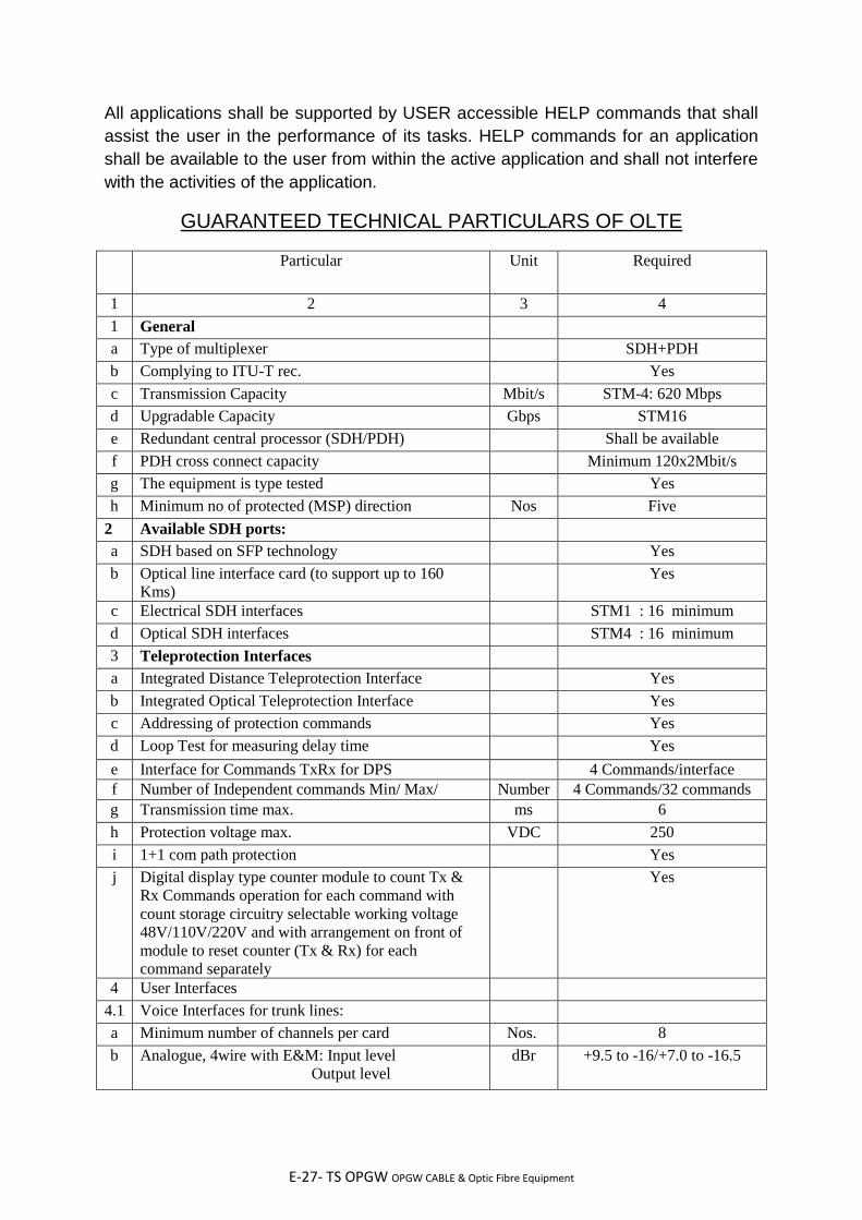
E-27- TS OPGW OPGW CABLE & Optic Fibre Equipment
All applications shall be supported by USER accessible HELP commands that shall
assist the user in the performance of its tasks. HELP commands for an application
shall be available to the user from within the active application and shall not interfere
with the activities of the application.
GUARANTEED TECHNICAL PARTICULARS OF OLTE
Particular Unit Required
1 2 3 4
1 General
a Type of multiplexer SDH+PDH
b Complying to ITU-T rec. Yes
c Transmission Capacity Mbit/s STM-4: 620 Mbps
d Upgradable Capacity Gbps STM16
e Redundant central processor (SDH/PDH) Shall be available
f PDH cross connect capacity Minimum 120x2Mbit/s
g The equipment is type tested Yes
h Minimum no of protected (MSP) direction Nos Five
2 Available SDH ports:
a SDH based on SFP technology Yes
b Optical line interface card (to support up to 160
Kms)
Yes
c Electrical SDH interfaces STM1 : 16 minimum
d Optical SDH interfaces STM4 : 16 minimum
3 Teleprotection Interfaces
a Integrated Distance Teleprotection Interface Yes
b Integrated Optical Teleprotection Interface Yes
c Addressing of protection commands Yes
d Loop Test for measuring delay time Yes
e Interface for Commands TxRx for DPS 4 Commands/interface
f Number of Independent commands Min/ Max/ Number 4 Commands/32 commands
g Transmission time max. ms 6
h Protection voltage max. VDC 250
i 1+1 com path protection Yes
j Digital display type counter module to count Tx &
Rx Commands operation for each command with
count storage circuitry selectable working voltage
48V/110V/220V and with arrangement on front of
module to reset counter (Tx & Rx) for each
command separately
Yes
4 User Interfaces
4.1 Voice Interfaces for trunk lines:
a Minimum number of channels per card Nos. 8
b Analogue, 4wire with E&M: Input level
Output level
dBr +9.5 to -16/+7.0 to -16.5

E-27- TS OPGW OPGW CABLE & Optic Fibre Equipment
c Analogue, 2wire with E&M: Input level
Output level
dBr +9.5 to -12.5-1.0 to -20
4.2 Voice Interfaces for remote subscriber:
a 2wire, subscriber side dBr -5to+4 / -7.5to-1
b Minimum number of subscriber Nos. 10
5 Data module
a V.24/V.28 (RS-232) minimum ports/interface Nos. 4
b V-35 minimum ports/interface Nos. 4
c Integrated LAN port available of DATA Interface Yes
d Software programmable board available to assign
different types of data interface to each port
Yes
6 Ethernet interface
a Ethernet: ports (Optical/Electrical) No. 4 ports
b Ethernet: Router functionality
Routing protocols Static IP route OSPF
7 Integrated alarm gathering module:
a Number of external alarms per module No. 8
8 Configuration Management
Type/Name of configuration tool
a For local/remote operation Yes/Yes
b Data communication network (DCN) Ethernet /IP
c Integrated management for SDH/PDH Yes
9 Network Management System
Type/Name of configuration tool
a For local/remote operation Yes/Yes
b Data communication network (DCN) TCP/IP
c Integrated management of SDH/PDH Yes
10 Power Supply
a Operation VDC 48
b Fully redundant power supply (for SDH/PDH) Yes
c Dual power feeder Yes
d AC power supply VAC 230
------------------------------------------End of the Section--------------------------------------------
GUARANTEED TECHNICAL PARTICULARS OF OPGW CABLE & HARDWARE
ACCESSORIES
GUARANTEED TECHNICAL PARTICULARS OF OLTE
Particular Unit Required
1 2 3 4

E-27- TS OPGW OPGW CABLE & Optic Fibre Equipment
1 General
a Type of multiplexer SDH+PDH
b Complying to ITU-T rec. Yes
c Transmission Capacity Mbit/s STM-4: 620 Mbps
d Upgradable Capacity Gbps STM16
e Redundant central processor (SDH/PDH) Shall be available
f PDH cross connect capacity Minimum 32x2Mbit/s
g The equipment is type tested Yes
h Minimum no of protected (MSP) direction Nos Three (expandable up to four
MSP directions of which at
least two directions support
STM-16)
2 Available SDH ports:
a SDH based on SFP technology Yes
b Optical line interface card (to support up to 160 Kms) Yes
c Electrical SDH interfaces E1, Electrical interface
d Optical SDH interfaces 6 ports minimum
3 Teleprotection Interfaces External Teleprotection
interface via
G.702(2mbps,E1).
There shall be option for the
interface of future integration
of protection coupler.
4 User Interfaces
4.1 Voice Interfaces for trunk lines:
a Minimum number of channels per card Nos. 8
b Analogue, 4wire with E&M: Input level
Output level
dBr +9.5 to -16/+7.0 to -16.5
c Analogue, 2wire with E&M: Input level
Output level
dBr +9.5 to -12.5-1.0 to -20
4.2 Voice Interfaces for remote subscriber:
a 2wire, subscriber side dBr -5to+4 / -7.5to-1
b Minimum number of subscriber Nos. 10
5 Data module
a V.24/V.28 (RS-232) minimum ports/interface Nos. 4
b V-35 minimum ports/interface Nos. 4
c Integrated LAN port available of DATA Interface Yes
d Software programmable board available to assign
different types of data interface to each port
Yes
6 Ethernet interface
a Ethernet: ports (Optical/Electrical) No. Ethernet-4 ports(Electrical)
Required and there shall be
option for Ethernet port
(optical) for future interface
of optical signal
b Ethernet: Router functionality
Routing protocols Ethernet interface unit with
layer-2 switching

E-27- TS OPGW OPGW CABLE & Optic Fibre Equipment
functionality.
7 Integrated alarm gathering module:
a Number of external alarms per module No. 8
8 Configuration Management
Type/Name of configuration tool
a For local/remote operation Yes/Yes
b Data communication network (DCN) Ethernet /IP
c Integrated management for SDH/PDH Yes
9 Network Management System
Type/Name of configuration tool
a For local/remote operation Yes/Yes
b Data communication network (DCN) TCP/IP
c Integrated management of SDH/PDH Yes
10 Power Supply
a Operation VDC 48
b Fully redundant power supply (for SDH/PDH) Yes
c Dual power feeder Yes
d AC power supply VAC 230