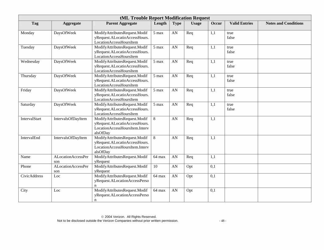
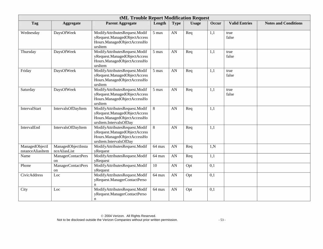
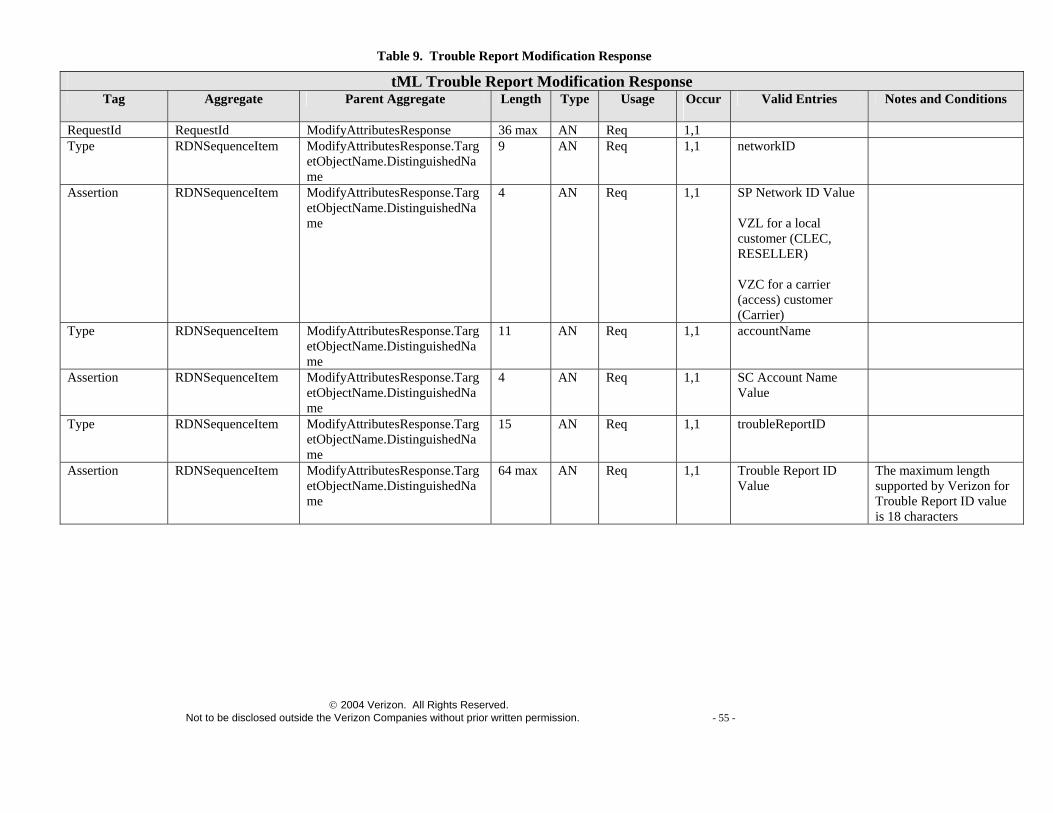
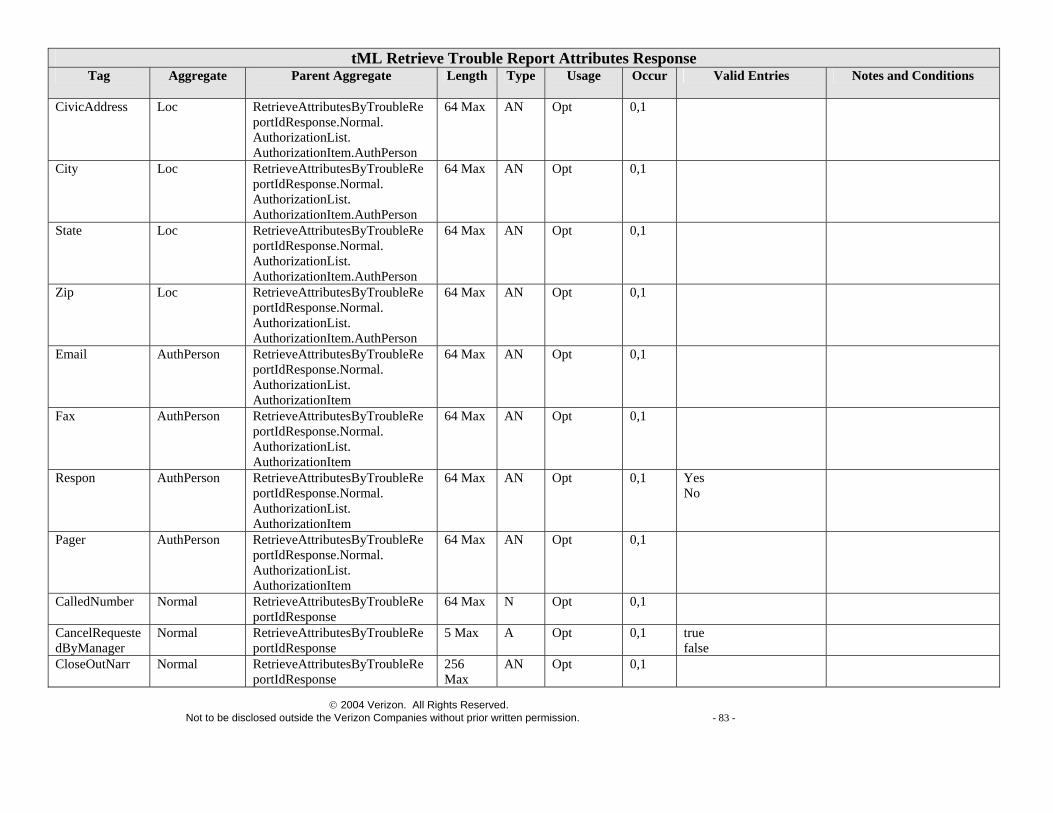
technical specifications for taxi (web services using tml)
TRANSCRIPT


- 165 -
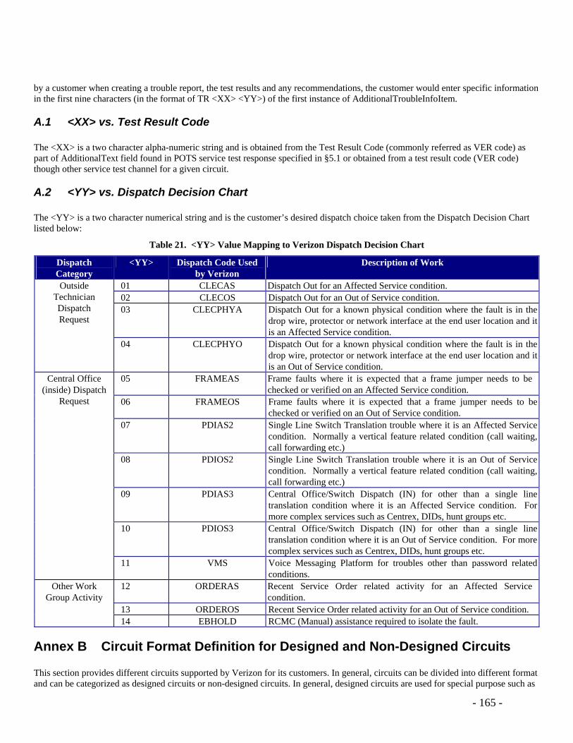
by a customer when creating a trouble report, the test results and any recommendations, the customer would enter specific information in the first nine characters (in the format of TR <XX> <YY>) of the first instance of AdditionalTroubleInfoItem.
A.1 <XX> vs. Test Result Code The <XX> is a two character alpha-numeric string and is obtained from the Test Result Code (commonly referred as VER code) as part of AdditionalText field found in POTS service test response specified in §5.1 or obtained from a test result code (VER code) though other service test channel for a given circuit.
A.2 <YY> vs. Dispatch Decision Chart The <YY> is a two character numerical string and is the customer’s desired dispatch choice taken from the Dispatch Decision Chart listed below:
Table 21. <YY> Value Mapping to Verizon Dispatch Decision Chart
Dispatch Category
<YY> Dispatch Code Used by Verizon
Description of Work
01 CLECAS Dispatch Out for an Affected Service condition. 02 CLECOS Dispatch Out for an Out of Service condition. 03 CLECPHYA Dispatch Out for a known physical condition where the fault is in the
drop wire, protector or network interface at the end user location and it is an Affected Service condition.
Outside Technician Dispatch Request
04 CLECPHYO Dispatch Out for a known physical condition where the fault is in the drop wire, protector or network interface at the end user location and it is an Out of Service condition.
05 FRAMEAS Frame faults where it is expected that a frame jumper needs to be checked or verified on an Affected Service condition.
06 FRAMEOS Frame faults where it is expected that a frame jumper needs to be checked or verified on an Out of Service condition.
07 PDIAS2 Single Line Switch Translation trouble where it is an Affected Service condition. Normally a vertical feature related condition (call waiting, call forwarding etc.)
08 PDIOS2 Single Line Switch Translation trouble where it is an Out of Service condition. Normally a vertical feature related condition (call waiting, call forwarding etc.)
09 PDIAS3 Central Office/Switch Dispatch (IN) for other than a single line translation condition where it is an Affected Service condition. For more complex services such as Centrex, DIDs, hunt groups etc.
10 PDIOS3 Central Office/Switch Dispatch (IN) for other than a single line translation condition where it is an Out of Service condition. For more complex services such as Centrex, DIDs, hunt groups etc.
Central Office (inside) Dispatch
Request
11 VMS Voice Messaging Platform for troubles other than password related conditions.
12 ORDERAS Recent Service Order related activity for an Affected Service condition.
13 ORDEROS Recent Service Order related activity for an Out of Service condition.
Other Work Group Activity
14 EBHOLD RCMC (Manual) assistance required to isolate the fault.
Annex B Circuit Format Definition for Designed and Non-Designed Circuits This section provides different circuits supported by Verizon for its customers. In general, circuits can be divided into different format and can be categorized as designed circuits or non-designed circuits. In general, designed circuits are used for special purpose such as

- 166 -
dedicated lines, connections between different switches, etc. Designed circuits are commonly used for carrying digital signals. On the other hand, non-designed circuits are commonly used for carrying POTS signals among other signals. The circuit id is used to populate the Assertion tag value of Type/Assertion pair in the last RDNSequenceItem under ManagedObjectInstance with Type tag value as serviceID for a Trouble Report Create request.
B.1 Serial Number Format Circuit
B.1.1 Circuit Definition – “S” Type
Table 22. Serial Format Circuit – "S" Type
Serial Number Format Start Max Size Notes XX/AAAX/NNNNNNXXXX/AAAA/XXX N – Numerical
A – Alpha X – either Numerical (N) or Alpha (A) including space
Header LineType="S" State Code determined by CLCICompanyCode
This may or may not be possible
Child Aggregate tags are CLCIPrefix Char 1 2 Prefix CLCISvcMod After 1st / 4 The first two characters are
Service Code. The next two characters are Modifier.
CLCISerialNum After 2nd / 6 Serial Number CLCISuffix 7th char after 2nd / 4 Suffix CLCICompanyCode After 3rd / 4 Company Assigning Circuit ID CLCISegment After 4th / 3 Segment Number
B.1.2 Circuit Definition – “3” Type
Table 23. Serial Format Circuit – "3" Type
Serial Number Format Start Max Size Notes XX/AAAX/NNNNNNXXXX/AAAA/XXX N – Numerical
A – Alpha X – either Numerical (N) or Alpha (A) including space
Header LineType="3" “3” type circuit is an old generation of “S” type circuit.
State Code determined by CLCICompanyCode
This may or may not be possible
Child Aggregate tags are CLCIPrefix Char 1 2 Prefix

- 167 -
Serial Number Format Start Max Size Notes CLCISvcMod After 1st / 4 The first two characters are
Service Code. The next two characters are Modifier. (For “3” type circuit, the total length of Service Code and Modifier is usually 2 to 3 characters).
CLCISerialNum After 2nd / 6 Serial Number Additional spaces are required to pad out a short (< 6 digits) Serial Number when a Suffix is present
CLCISuffix 7th char after 2nd / 4 Suffix CLCICompanyCode After 3rd / 4 Company Assigning Circuit ID CLCISegment After 4th / 3 Segment Number
B.1.3 Designed vs. Non-Designed Serial (“S”) type circuit can be either designed or non-designed circuit. Some common “S” type designed circuits include DS1 circuits as well as other high bandwidth digital circuits. “S” type circuits can also be non-designed. Examples are line sharing (commonly marked with URXX as service modifier) and line splitting (commonly marked with SWXX as service modifier) circuits for caring both POTS and DSL signals on a same circuit, and unbundled loop (so-called UNE loop with TXNU as service modifier).
B.1.4 Designed Circuit Examples 32/LGGS/119578/NY 77/LDGS/222222/PA
96/PRNA/410163
74/FDDA/172341/NE 96/QLS/4141/NY type “3” circuit 74/QLS/43318 type “3” circuit
7/QLL/44903 type “3” circuit 96/VM/1508 type “3” circuit 9/LL/704/NY type “3” circuit 15/HCGS/500022/PA 11/LGGS/907432/PA 15/LG/861554/PA type “3” circuit 13/LJGS/870872/PA 11/LDFS/882266/PA 41/LGGS/234567654/GTSE/321
B.1.5 Non-Designed Circuit Examples
96/SWXX/12323/NY UB/TXNU/733164/NJ UB/TXNU/734349/CD 43/TXNU/001453/GTES UB/TXNU/753541/PA UB/TXNU/732261/NJ

- 168 -
UB/TXNU/143252/CM SL/TXNU/979779/PA
36/IBZZ/425440/CD 71/IBSD/600693/NE /IBZD/131857/NJ
B.2 Telephone Number Format Circuit
B.2.1 Circuit Definition
Table 24. Telephone Format Circuit – "T" Type
Telephone Number Format Start Max Size
Notes
XX/AAAX/NNN/NNN/NNNN/XXXXX/XXX N – Numerical A – Alpha X – either Numerical (N) or Alpha (A) including space
Header LineType="T" State Code determined by first six characters of CLCITelephoneNumber (aka NPANXX)
This may or may not be possible
Child Aggregate Tags are: CLCIPrefix 1st char. 2 Prefix CLCISvcMod After 1st / 4 The first two characters are
Service Code. The next two characters are Modifier.
CLCITelephoneNumber (Strip out embedded /'s to end up with tag value of size 10)
After 2nd / 12 The first three characters is NPA Code; the next three characters is Central Office Unit Code; the remaining four characters is Line Number Code (all subject that the slash “/” delimiter is present and all three sections are present).
CLCIExtension After 5th / 5 Extension Number or Trunk Code CLCISegment After 6th / 3 Segment Number
B.2.2 Designed vs. Non-Designed Telephone (“T”) type circuit can be either designed or non-designed circuit.
B.2.3 Designed Circuit Examples
13/SEGS/717/236/9829/0001 11/SE/215/016/4003 11/SFGS/302/428/9968/0022 11/SFGS/215/283/9464/0005 12/SEGS/717/455/2692/4 11/SBGS/215/569/9519 11/SBGS/302/655/2376 32/SBGY/212/269/1270

- 169 -
B.2.4 Non-Designed Circuit Examples
/NDDA/201/365/1560/1 /TKNA/201/365/7300/G/1 /CLNZ/201/365/7289/1 /CLNZ/201/365/7262/13 /CLNZ/201/365/4954/1 36/TKNA/315/449/8182 96/CLNA/212/480/0895 96/FXNA/212/962/0705 96/OPNA/212/509/2982 66/SLNA/508/234/9931//004 62/SLNA/978/544/7433//005 61/HNCA/508/624/8400/D26 65/HNCA/508/751/4200/D48 66/WXNA/800/922/8202/1 66/HNCA/508/795/2000/D51 62/FXNA/978/342/0000//003 62/OPNT/978/433/6685/001
66/SLNA/508/476/3291//002 3 /FXLT/610/524/1030/B 3 /OSNT/302/856/5369 3 /DONT/302/421/0048/6 3 /DINA/302/453/6900/0008 3 /TKNC/302/656/5020/010 3 /DINT/302/995/8700/06
B.3 Carrier Facility Format Circuit
B.3.1 Circuit Definition
Table 25. Carrier Facility Format Circuit – "C" Type
Designed Carrier Format Start Max Size
Notes
XXXXX/XXXXXX/AAAAAAXXAXX/AAAAAAXXAXX N – Numerical A – Alpha X – either Numerical (N) or Alpha (A) including space
Header LineType="C" State Code Determined by 5-6 chars of LocationZ Child Aggregate Tags are CarrierFacilityDesignation Start of string 5 CarrierFacilityType After 1st / 6 LocationA After 2nd / 11 Location ID (Office A) LocationZ After 3rd / 11 Location ID (Office Z)
A carrier facility circuits system generally provides several telecommunication channels over a bi-directional path. A carrier facility circuits generally has multiplex equipment at the two terminal locations (Office A & Z). The interconnecting path consists of (1) higher level facility systems, (2) facility assemblies, or (3) combinations of facility assemblies and facility assemblies. In general, a

- 170 -
carrier facility system provides assignable channels which have lower information rates than the carrier systems aggregate information capacity. All carrier facility format circuits are designed circuits.
B.3.2 Circuit Examples 437/T1ZF/PITBPADTDC4/PITBPADTHVC
5101/T1/CLPKMDBWHVA/WASHDCBKCG0 111/T1/TINYDBAAW99/TINYDBBB 115/T1/TINYDBAAW99/TINYDBBB 101/T1ZF/MNSSVASPW01/MNSSVAXADC0 00001/T1Z/IRNGTXXADS0/IRNGTXXBDS0
B.4 Message Format Circuit
B.4.1 Circuit Definition
Table 26. Message Format Circuit – "M" Type
Designed Message Trunk Format Start Max Size
Notes
NNNN/AAXXAAXXXXXXX/AAAAAAXXXXX/XX/AAAAAAXXXXX N – Numerical A – Alpha X – either Numerical (N) or Alpha (A) including space
Header LineType="M" Header State Code determined by 5-6 chars of TrunkLocationZ Child Aggregate Tags TrunkNumber Start of string 4 Trunk Number TrunkDesc After 1st / 13 The first two characters is
Traffic Class; the next two characters is Office Class; followed by two characters Traffic Use; the last eight characters is Trunk Type Modifier. The whole section is so-called Trunk Type.
TrunkLocationA After 2nd / 11 Location ID (Office A) TrunkPulse After 3rd / 2 Address Signaling TrunkLocationZ After 4th / 11 Location ID (Office Z)
All message format circuits are designed circuits.
B.4.2 Circuit Examples

- 171 -
1/PH55IE/THOKCAXFDS1/77/THOKCAXH49K 48/PH55IE/THOKCAXFDS1/77/THOKCAXH49K 24/DF-5PKTK/LMPCCAXFH01/--/SNTMCAXF00W
528/PH-5EDG1/BLTNCAAD1MD/77/YUCPCAXF79M 122/DF5-EF/ORCTCAXG93K/MM/SNTMCAAV1MD 1313/DF-53IR/BURLVTMADS0/M-/WRJTVTGA9GT 0014/PH-5ED/PHLAPAPHA01/-M/SPFDPASFDC0 0001/DF55IE/IRNGTXXADS0/MM/IRNGTXXBDS0 12/PH-5ED/ERIEPABB1MD/MM/ERIEPAXEDS0
B.5 POTS Format Circuit
B.5.1 Circuit Definition
Table 27. POTS Format Circuit – "P" Type
Non Designed Start Max Size Notes NNNNNNNNNN N – Numerical
Header LineType="P" CLCITelephoneNumber Use entire string 10 The length is always 10
POTS format circuits are non-designed only. They are used to represent 10 digit telephone numbers.
B.5.2 Circuit Examples 7039746778 7039745182 7039745149 7032126178


- 176 -
Annex D Acronym List Name Description ACNA Access Customer Name Abbreviation ANSI American National Standards Institute AVC Attribute Value Change B2B Business To Business CLEC Competitive Local Exchange Carrier ECC Exchange Carrier Code FEP Facility Equipment Provisioned FTTP Fiber To The Premise GMT Greenwich MeanTime HTTP Hypertext Transfer Protocol HTTPS Hypertext Transfer Protocol - Secure IEC Interexchange Carriers NPA Numbering Plan Area (Area Code) NXX Telephone Exchange Number OAM&P Operations, Administration, Maintenance and Provisioning POTS Plain Old Telephone Service RPC Remote Procedure Call SOAP Simple Object Access Protocol TA Trouble Administration TAPP Trouble Administration Pre-Production TAXI Trouble Administration XML Interface TSP Telephone Service Priority URL Uniform Resource Locator WSDL Web Services Description Language XML Extensible Markup Language tML Telecommunications Markup Language