technical specifications scania 176 kva natural gas
TRANSCRIPT
Specification sheet 176 kVA 50Hz 150 kW 50Hz
Your partner for energy
Natural Gas Generator set SGI-12 engine AEH176GW
1500 r/min (50 Hz) 1800 r/min (60 Hz)
COP PRP ESP COP PRP ESP
SGI-12 STM kWm 205 205 225 205 205 225
SGI-12 CGM kWm 205 205 225 205 205 225
These outputs have been determined under certain given test conditions according to the international performance standard ISO 3046 Ratings PRP: Prime power ESP: Maximum stand-by power Descriptions of ratings and other power information, see “General” Standard equipment Impco gas mixer Speed governing with an electronically controlled integral actuator Electronic ignition system, pulse pick-up on the crankshaft Separate ignition coils for each spark plug Spark plug leads with extensions Cable harness Turbocharger 90 º exhaust bend, adjustable direction. Dry exhaust manifold Charge-air cooler (air to water) Fan with fan guard and fan-ring (STM engine) 2nd cooling water-pump for the charge-air cooler circuit (STM engine) Main cooling water-pump for the engine block and heads cooling (STM engine) Lub oil filtration in 2 stages, filter and centrifuge Integral engine oil cooler Starting motor, 1 pole, 6,7 kW, 24V Charging alternator 65A, 24V SAE 1 flywheel housing SAE 14" industrial flywheel Engine mounted air filter Engine front suspension Poly-V belt transmission with guarding (STM engine)
Generator set data sheet 176 Kva Prime Your partner for energy
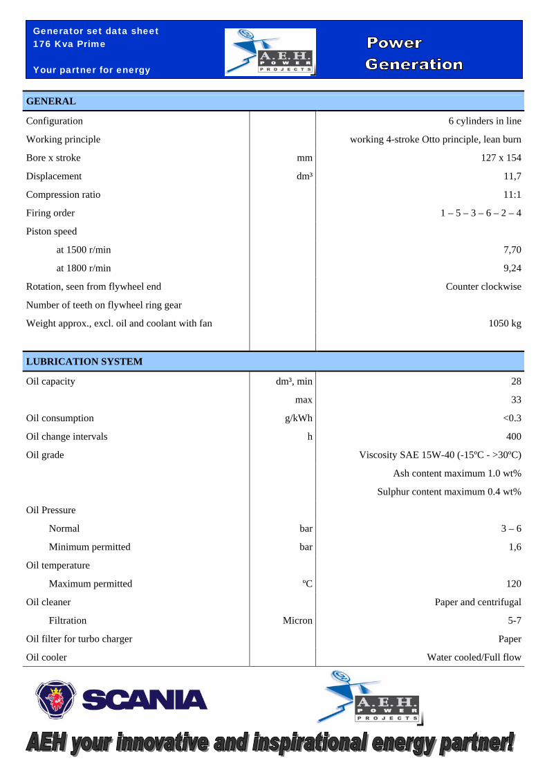
GENERAL
Configuration 6 cylinders in line
Working principle working 4-stroke Otto principle, lean burn
Bore x stroke mm 127 x 154
Displacement dm³ 11,7
Compression ratio 11:1
Firing order 1 – 5 – 3 – 6 – 2 – 4
Piston speed
at 1500 r/min 7,70
at 1800 r/min 9,24
Rotation, seen from flywheel end Counter clockwise
Number of teeth on flywheel ring gear
Weight approx., excl. oil and coolant with fan 1050 kg
LUBRICATION SYSTEM
Oil capacity dm³, min 28
max 33
Oil consumption g/kWh <0.3
Oil change intervals h 400
Oil grade Viscosity SAE 15W-40 (-15ºC - >30ºC)
Ash content maximum 1.0 wt%
Sulphur content maximum 0.4 wt%
Oil Pressure
Normal bar 3 – 6
Minimum permitted bar 1,6
Oil temperature
Maximum permitted ºC 120
Oil cleaner Paper and centrifugal
Filtration Micron 5-7
Oil filter for turbo charger Paper
Oil cooler Water cooled/Full flow
Generator set data sheet 176 Kva Prime Your partner for energy
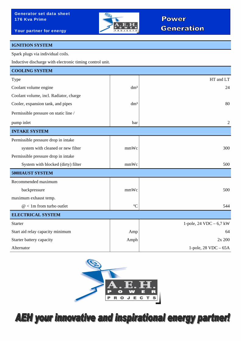
IGNITION SYSTEM
Spark plugs via individual coils.
Inductive discharge with electronic timing control unit.
COOLING SYSTEM
Type HT and LT
Coolant volume engine dm³ 24
Coolant volume, incl. Radiator, charge
Cooler, expansion tank, and pipes dm³ 80
Permissible pressure on static line /
pump inlet bar 2
INTAKE SYSTEM
Permissible pressure drop in intake
system with cleaned or new filter mmWc 300
Permissible pressure drop in intake
System with blocked (dirty) filter mmWc 500
500HAUST SYSTEM
Recommended maximum
backpressure mmWc 500
maximum exhaust temp.
@ < 1m from turbo outlet ºC 544
ELECTRICAL SYSTEM
Starter 1-pole, 24 VDC – 6,7 kW
Start aid relay capacity minimum Amp 64
Starter battery capacity Amph 2x 200
Alternator 1-pole, 28 VDC – 65A
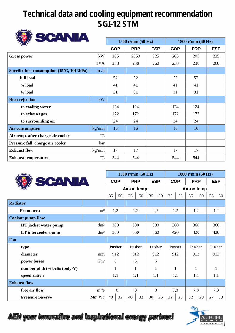
Technical data and cooling equipment recommendation SGI-12 STM
1500 r/min (50 Hz) 1800 r/min (60 Hz)
COP PRP ESP COP PRP ESP Gross power kW 205 2050 225 205 205 225
kVA 238 238 260 238 238 260
Specific fuel consumption (15ºC, 1013hPa) m³/h
full load 52 52 52 52
¾ load 41 41 41 41
½ load 31 31 31 31
Heat rejection kW
to cooling water 124 124 124 124
to exhaust gas 172 172 172 172
to surrounding air 24 24 24 24
Air consumption kg/min 16 16 16 16
Air temp. after charge air cooler ºC
Pressure fall, charge air cooler bar
Exhaust flow kg/min 17 17 17 17
Exhaust temperature ºC 544 544 544 544
1500 r/min (50 Hz) 1800 r/min (60 Hz)
COP PRP ESP COP PRP ESP
Air-on temp. Air-on temp. 35 50 35 50 35 50 35 50 35 50 35 50
Radiator
Front area m² 1,2 1,2 1,2 1,2 1,2 1,2
Coolant pump flow
HT jacket water pump dm³ 300 300 300 360 360 360
LT intercooler pump dm³ 360 360 360 420 420 420
Fan
type Pusher Pusher Pusher Pusher Pusher Pusher
diameter mm 912 912 912 912 912 912
power losses Kw 6 6 6
number of drive belts (poly-V) 1 1 1 1 1 1
speed ration 1:1 1:1 1:1 1:1 1:1 1:1
Exhaust flow
free air flow m³/s 8 8 8 7,8 7,8 7,8
Pressure reserve Mm Wc 40 32 40 32 30 26 32 28 32 28 27 23
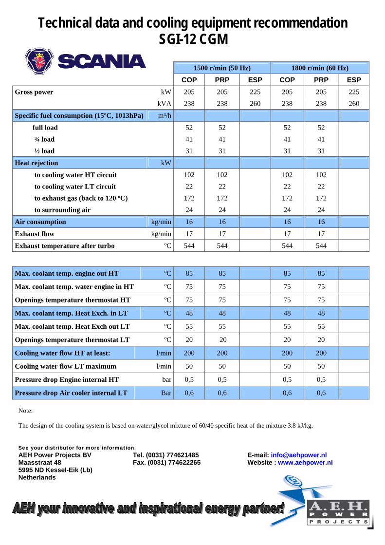
Technical data and cooling equipment recommendation SGI-12 CGM
1500 r/min (50 Hz) 1800 r/min (60 Hz)
COP PRP ESP COP PRP ESP Gross power kW 205 205 225 205 205 225
kVA 238 238 260 238 238 260
Specific fuel consumption (15ºC, 1013hPa) m³/h
full load 52 52 52 52
¾ load 41 41 41 41
½ load 31 31 31 31
Heat rejection kW
to cooling water HT circuit 102 102 102 102
to cooling water LT circuit 22 22 22 22
to exhaust gas (back to 120 ºC) 172 172 172 172
to surrounding air 24 24 24 24
Air consumption kg/min 16 16 16 16
Exhaust flow kg/min 17 17 17 17
Exhaust temperature after turbo ºC 544 544 544 544
Max. coolant temp. engine out HT ºC 85 85 85 85
Max. coolant temp. water engine in HT ºC 75 75 75 75
Openings temperature thermostat HT ºC 75 75 75 75
Max. coolant temp. Heat Exch. in LT ºC 48 48 48 48
Max. coolant temp. Heat Exch out LT ºC 55 55 55 55
Openings temperature thermostat LT ºC 20 20 20 20
Cooling water flow HT at least: l/min 200 200 200 200
Cooling water flow LT maximum l/min 50 50 50 50
Pressure drop Engine internal HT bar 0,5 0,5 0,5 0,5
Pressure drop Air cooler internal LT Bar 0,6 0,6 0,6 0,6 Note: The design of the cooling system is based on water/glycol mixture of 60/40 specific heat of the mixture 3.8 kJ/kg. See your distributor for more information. AEH Power Projects BV Tel. (0031) 774621485 E-mail: [email protected] Maasstraat 48 Fax. (0031) 774622265 Website : www.aehpower.nl 5995 ND Kessel-Eik (Lb) Netherlands
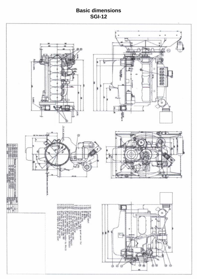
Basic dimensions SGI-12