technical standards for the multifamily building analyst
TRANSCRIPT

THE SYMBOL OF EXCELLENCE FOR HOME PERFORMANCE CONTRACTORS
Technical Standards for the Multifamily Building Analyst Professional BPI STANDARDS
FEBRUARY 20, 2008


MODULE CATEGORY STANDARD METHOD OR
TECHNIQUE SPECIAL MATERIALS OR EQUIPMENT
2/20/08 mda Page 2 of 22
1. Communication and Reporting 1.1 Communication and
Reporting General The Auditor shall comply with all elements and
requirements described within the BPI Code of Ethics.
BPI Code of Ethics
1.2 Communication and Reporting
General All assumptions that are made to complete the analysis of the building including data inputs to any software tool shall be documented and disclosed in the project report.
1.3 Communication and Reporting
General Where feasible, a variety of options shall be considered when recommending improvements to the building. New and emerging technologies and approaches to EEM’s and energy cost reduction shall be evaluated and recommended as appropriate in the context of the particular client’s needs, energy costs, technological capabilities of the site and its staff, the building owner’s social mission, etc.
1.4 Communication and Reporting
General Whenever the recommended measures includes the disposal of hazardous material, equipment or other building components or materials, the project report shall note that all appropriate state and federal recommendations should be followed. Example: Refrigerators and air conditioning units must be removed and decommissioned in compliance with EPA Clean Air Act and other relevant State regulations.
EPA Regulations
1.5 Communication and Reporting
Pre-Site Visit Site contact information for key building representatives shall be collected prior to visiting the site to conduct a building audit. Data to be collected and recorded includes: contact names and numbers for key members of the following groups: building owner(s), manager(s), maintenance staff, and occupant

MODULE CATEGORY STANDARD METHOD OR
TECHNIQUE SPECIAL MATERIALS OR EQUIPMENT
2/20/08 mda Page 3 of 22
representative(s). 1.6 Communication and
Reporting Pre-Site Visit Determine primary or most important decision
maker(s) for the building/complex. All reasonable efforts shall be made to make site visit appointments convenient for all of the key building representatives.
1.7 Communication and Reporting
Pre-Site Visit Complete energy and water data, including bulk-delivered fuels, when available, must be collected for analysis prior to the site visit. A minimum of one full year of utility data is required (at least 15 months suggested including: all fuel, electric, water, sewer, and other resource consumption, demand, and cost information. Utility data must be at least bi-monthly as metered by the utility or provider, not just an annual summation. If complete data is not available, refer to Section 2.11 to 2.18 for additional requirements regarding interpretation of modeled results. For buildings with individually metered units, refer to Section 3.1 for requirements related to sampling.
1.8 Communication and Reporting
Site Visit Blueprints and/or as-built drawings shall be requested and reviewed prior to visiting the building or as part of the site visit when they are available. Refer to section 3.2 for blueprint evaluation.
Blueprints
1.9 Communication and Reporting
Site Visit An interview must be completed with each available representative decision maker as defined by section 3.1.
1.10 Communication and Site Visit The interview shall be used to obtain

MODULE CATEGORY STANDARD METHOD OR
TECHNIQUE SPECIAL MATERIALS OR EQUIPMENT
2/20/08 mda Page 4 of 22
Reporting information about building maintenance and operations, capital improvement plans, and aspects of the building that function well, adequately, or poorly. Interview results shall be incorporated in the final project report.
1.11 Communication and Reporting
Site Visit When requested, confidentiality of personal information obtained during inspections and interviews must be maintained by the auditor.
1.12 Communication and Reporting
Site Visit When working with building owners, occupants, and staff, the auditor shall make a reasonable effort to understand the cultural context of the people and situations involved and be respectful of any unique conditions which may affect the auditor’s ability to adequately obtain accurate and complete data, especially during the interview process.
1.13 Communication and Reporting
Site Visit Data collected during the interview and audit process shall include sufficient information to produce a comprehensive work scope to address comfort, health and safety, durability, and energy efficiency problems and opportunities.
1.14 Communication and Reporting
Report A comprehensive report shall be provided to the building decision maker(s) based on the information gathered during the site visit and subsequent analysis. This report must include, at a minimum: Existing conditions Recommended measures Utility/Water consumption analysis Cost/Benefit Analysis
1.15 Communication and Reporting
Report Reasonable efforts shall be made to consider all viable retrofit options to improve comfort,

MODULE CATEGORY STANDARD METHOD OR
TECHNIQUE SPECIAL MATERIALS OR EQUIPMENT
2/20/08 mda Page 5 of 22
health & safety, durability, and energy efficiency.
1.16 Communication and Reporting
Report The existing maintenance plan shall be considered for its adequacy to ensure the persistence of savings and durability of building components, including maintenance of: mechanical equipment, light fixtures and bulb replacements, building-owned appliances, and water saving devices. When plan is found to be lacking or deficient, a recommendation that a maintenance plan be developed shall be made as part of the project report.
2. Analysis 2.1 Analysis General When assumptions are used in the course
of analyzing data, modeling building energy use, loads, or other performance parameters; these assumptions shall be clearly documented and justification provided in the analysis report and disclosed to the building owner/decision-maker.
2.2 Analysis Utility Usage Analysis
For each energy type or utility resource being consumed a whole building analysis shall be completed, in addition: For sites with multiple buildings, a
whole building analysis shall be completed, at a minimum, for each
Refer to Energy Conservation for Housing

MODULE CATEGORY STANDARD METHOD OR
TECHNIQUE SPECIAL MATERIALS OR EQUIPMENT
2/20/08 mda Page 6 of 22
building type on the site based on building geometry, occupancy type, and energy-efficiency characteristics. (For example, if buildings of the same geometry and occupancy have undergone different renovations or have different types of HVAC equipment, an energy analysis shall be completed for each different building configuration.)
Apply apartment unit level analysis when units are individually metered and billed, using BPI sampling procedures in Section 3.1
For dual fuel situations, evaluate consumption based on BTU’s consumed
2.3 Analysis Utility Usage Analysis
Energy use indices shall be established for each energy and water use in the building
Refer to Energy Conservation for Housing - A Workbook by Abt Associates
2.4 Analysis Utility Usage Analysis
Disaggregated consumption shall be calculated based on actual data, when available, for: Baseload for each fuel DHW consumption Cooling consumption Heating consumption Other identifiable block loads (e.g. pool
heaters, sidewalk ice melting, etc.) Calculated consumption shall be used to identify savings opportunities and cross-referenced to the energy model to verify
Refer to Energy Conservation for Housing - A Workbook by Abt Associates

MODULE CATEGORY STANDARD METHOD OR
TECHNIQUE SPECIAL MATERIALS OR EQUIPMENT
2/20/08 mda Page 7 of 22
end-use allocations. Analysis shall include evaluation of savings opportunities related to load-shifting, peak shaving, and demand reduction.
2.5 Analysis Utility Usage Analysis
Utility usage analysis shall be calculated with all available data
2.6 Analysis Utility Usage Analysis
Fuel usage data must be normalized using weather data for the weather station closest to the building location (or adjusted and documented according to local anomalies) and billing period being evaluated. The weather station used for the analysis shall be included in the analysis documentation.
2.7 Analysis Utility Usage Analysis
Before the site visit, energy and water consumption shall be evaluated based on utility/fuel billing data, normalized as described in 2.6, and analyzed to identify anomalies. Possible explanations of the anomalies should be confirmed or rejected during the site visit. Document and explain identified anomalies and whether they were confirmed during the site visit.
2.8 Analysis Utility Usage Analysis
Graph monthly energy usage for each fuel for a minimum of 12 months for each building type analyzed, as defined in section 2.2)
2.9 Analysis Utility Usage Analysis
An estimating methodology shall be developed and documented to evaluate consumption that is lower than predicted values due to equipment downtime, vacancies, and/or other identifiable factors.

MODULE CATEGORY STANDARD METHOD OR
TECHNIQUE SPECIAL MATERIALS OR EQUIPMENT
2/20/08 mda Page 8 of 22
2.10 Analysis Utility Usage Analysis
If, upon initial review, the utility rate structure seems incorrect, recommend the building owner hire a qualified contractor to conduct a utility rate analysis
2.11 Analysis Energy Modeling An analytical energy model of the building’s pre and post-retrofit performance shall be completed using the data collected and accepted algorithms. The modeling process shall include calculated loads based on ASHRAE heating and cooling models and electrical equipment ratings and operating hours. Calculated loads shall be compared to utility usage analysis outputs and the results verified for consistency and accuracy. Analysis may be completed by hand, using spreadsheet calculations, or third-party energy audit software that has been independently validated.
ASHRAE Fundamentals Chapter 31
Manual calculations, spreadsheet analysis, or energy audit software approved by DOE for MF
2.12 Analysis Energy Modeling Data input to a computer analysis model shall be based on information gathered during the audit and site inspection. Building parameter data must be collected, prepared, and input accurately to accurately reflect the existing conditions of the building. If all or part of the model is based on building drawings, this must be documented in the analysis and the reason for the lack of site data identified.
Refer also to Oak Ridge National Labs, www.ornl.gov, for additional energy and building performance modeling tools.
2.13 Analysis Energy Modeling Adjustments in building description inputs used to calibrate the model must be justified

MODULE CATEGORY STANDARD METHOD OR
TECHNIQUE SPECIAL MATERIALS OR EQUIPMENT
2/20/08 mda Page 9 of 22
with explicit, transparent information and documented in the project report.
2.14 Analysis Energy Modeling Estimated energy savings for recommended EEM’s shall be calculated and accurately reflect interactivity of savings attributed to the recommended measures. Assumptions used in calculating estimated savings shall be clearly identified in the project report.
ASHRAE Fundamentals, Chapter 31
2.15 Analysis Energy Modeling Estimated savings calculated for custom measures shall include interactive effects with other recommended EEM’s. The results of custom calculations shall be fed back into the original modeling tool. Custom calculations and assumptions shall be clearly identified in the project report.
2.16 Analysis Energy Modeling Heating and cooling load calculations must incorporate changes to internal gains and losses from electrical savings where applicable. Special care shall be taken when separate analytical tools are used.
2.17 Analysis Energy Modeling Predicted energy savings must be compared against current usage to confirm that predictions are realistic. Document the percentage of total energy use to be saved and ensure that estimates are justified and do no exceed actual consumption.
2.18 Analysis Economic Analysis
An economic analysis shall be prepared that reflects inflation and discount rates
EIA, FEMP
2.19 Analysis Economic Analysis
Cost-estimates for all EEM’s shall be prepared and documented including measures to be installed and O&M recommendations. The basis for assumptions shall be included in the project

MODULE CATEGORY STANDARD METHOD OR
TECHNIQUE SPECIAL MATERIALS OR EQUIPMENT
2/20/08 mda Page 10 of 22
report. 2.20 Analysis Economic
Analysis Non-energy savings and costs resulting from retrofits (including O&M recommendations) shall be quantified and included in the project report.
2.21 Analysis Economic Analysis
Energy savings shall be calculated using appropriate methods
2.22 Analysis Economic Analysis
Economic analysis of the project shall include an evaluation of the allocation costs and benefits to the specific end use bill payers (owners, occupants, etc.)
2.23 Analysis Economic Analysis
Non-energy related benefits of the recommended measures shall be identified in the project report, including but not limited to: Health and safety improvements Societal benefits Environmental benefits Tenant satisfaction and reduced
turnover Avoided penalties
3. Diagnostics and Inspections 3.1 Diagnostics and
Inspections Sampling For all inspection and diagnostic testing
requiring a representative sample, use the following minimum criteria:
Sample units shall be selected to be representative of all available types of the equipment or building component being evaluated
Where unit performance may be dependent on the location in the building, the sample selected shall be

MODULE CATEGORY STANDARD METHOD OR
TECHNIQUE SPECIAL MATERIALS OR EQUIPMENT
2/20/08 mda Page 11 of 22
representative of all relevant sizes and locations in the building
If results of the initial minimum sample are inconclusive and/or inconsistent, additional units shall be evaluated, as needed
3.2 Diagnostics and Inspections
Blueprint Evaluation
Given the availability of blueprints, the existence and location of each of the following building elements shall be identified and documented prior to the site visit: potential air leakage paths building component assemblies for their
rated R-values and areas for input into heating/cooling load calculations
locations of potential thermal bridges identify types and schedule of mechanical
equipment and distribution system(s)
Blueprints
3.3 Diagnostics and Inspections
Blueprint Evaluation/ Site Visit
Information collected from the building drawings must be field-verified based on actual observed conditions. Wherever field conditions do not match design conditions, field data shall be used for analysis and reporting.
3.4 Diagnostics and Inspections
Site Visit Building performance and operating conditions that may create problems and/or are detrimental to the building and/or its occupants shall be identified and documented in the project report, related to: Health and safety Energy Efficiency Building Durability Occupant Comfort Readily Observable Code Issues Retrofit measures shall be recommended to

MODULE CATEGORY STANDARD METHOD OR
TECHNIQUE SPECIAL MATERIALS OR EQUIPMENT
2/20/08 mda Page 12 of 22
address any such conditions identified or problems identified shall be referred to a specialist when the issues are outside the auditor’s area of expertise.
3.5 Diagnostics and Inspections
Site Visit All necessary information shall be collected to conduct an adequate building heat loss/gain calculations and energy analysis calculations
3.6 Diagnostics and Inspections
Moisture The building shall be evaluated for existing moisture-related problems including a comprehensive visual inspection for moisture indicators and testing for hidden moisture in building components as needed including: around windows, wall AC sleeves, around toilets, and under sinks. Existing moisture related problems and their possible sources shall be identified and documented in the project report
See also BPI Best Practices for visual moisture inspection checklist, CERCH Protocols
Surface moisture meter
3.7 Diagnostics and Inspections
Ventilation The ventilation system shall be identified and documented by type and location for all systems serving individual apartments, common areas and the whole building. In addition, the following information shall be collected and documented based on field observations and occupant interviews: System type and location operation specifications usage/time schedule actual performance
See also BPI Best Practices, Ventilation System Inspection Checklist
Smoke pencil or other method to ensure movement of air through fan
3.8 Diagnostics and Inspections
Ventilation In buildings with ventilation fans (either in-unit or central) verify the direction of flow at the apartment grilles, based on the sampling protocol in section 3.1.
Smoke test at terminal registers to verify direction of airflow
Smoke pencil or other method to ensure movement of air

MODULE CATEGORY STANDARD METHOD OR
TECHNIQUE SPECIAL MATERIALS OR EQUIPMENT
2/20/08 mda Page 13 of 22
In buildings with central ventilation, the rooftop fan(s) shall be inspected for effective operation. The fan, motor, muffler, and shaft shall be inspected for dirt and obstructions where feasible.
3.9 Diagnostics and Inspections
Ventilation In buildings with central ventilation fans (including exhaust and supply air), each fan in the building shall be inspected for effective operation. The fan, motor, muffler, and shaft shall be inspected for dirt and obstructions where feasible. Problems identified shall be documented and included in the project report with recommendations to ensure proper maintenance and performance of these units and/or replacement units installed as part of the project work scope.
3.10 Diagnostics and Inspections
Ventilation When quantitative measurements are made of ventilation system airflows, results shall be compared and evaluated for compliance with design flows and applicable codes
3.11 Diagnostics and Inspections
Building Airflow Infiltration as a result of stack effect, wind effect, bypasses, etc. shall be evaluated using qualitative observations. (i.e. stairwells, elevator shafts, open skylights, dampers etc). Feasibility of air sealing shall be evaluated based upon building conditions and local codes.
3.12 Diagnostics and Inspections
Envelope Building component assemblies and their existing condition shall be field verified and documented including all of the following components: wall, floor, ceiling, window, door, and roof to the extent that these assemblies are readily observable.

MODULE CATEGORY STANDARD METHOD OR
TECHNIQUE SPECIAL MATERIALS OR EQUIPMENT
2/20/08 mda Page 14 of 22
3.13 Diagnostics and Inspections
Envelope A representative sample of the effective R-values of all component assemblies shall be determined based on field verified conditions and included in the building analysis
3.14 Diagnostics and Inspections
Envelope Possible locations for thermal bridging and any other building component assemblies that may impact energy usage or areas where cold surfaces may cause moisture to condense shall be identified through physical inspection, documented, and included in the building analysis.
3.15 Diagnostics and Inspections
Envelope When replacement windows are specified in the work scope, recommend pre and post-installation air tightness testing to verify leakage rates below 0.3 cfm/sqft @ 75 Pascals
AAMA Air Tightness Standards for Windows
4. Mechanical Systems 4.1 Mechanical Systems Equipment
Schedule For purposes of diagnosis and modeling, a schedule of HVAC and other mechanical equipment shall be developed. Schedule shall include sufficient detail about the mechanical systems to allow accurate modeling so that opportunities for energy savings will not be overlooked. Schedule should include: nameplate data, capacities, type of service, area served, age, other relevant characteristics and comments. Any assumptions shall be included in the project report.
4.2 Mechanical Systems Equipment Schedule
For diagnostic purposes, the mechanical systems operating schedule shall include all of the following central plant and building service equipment: boilers

MODULE CATEGORY STANDARD METHOD OR
TECHNIQUE SPECIAL MATERIALS OR EQUIPMENT
2/20/08 mda Page 15 of 22
burners chillers pumps heat exchangers fans emergency generators and other on-site
electrical generation equipment elevator motors controls and control settings and
sequences Refer to sections 4.21 for elevators and 5.1 for electrical.
4.3 Mechanical Systems Equipment Schedule
The Equipment Schedule shall include all of the following distributed equipment: AHU Packaged HVAC Mechanical ventilation fans Mechanically driven plumbing components
4.4 Mechanical Systems Equipment Schedule
The Equipment Schedule shall include in-apartment equipment and terminal elements (such as convectors, PTAC) where feasible. Use the sampling procedure in section 3.1
4.5 Mechanical Systems HVAC System HVAC system shall be identified by type based on field observations. Diagnostics and calculations appropriate to the system type shall be completed
4.6 Mechanical Systems Distribution Systems
Where signs of active or inactive air, water, and/or steam leakage are identified, the area shall be investigated to determine the source and documented, including leaks from: ductwork, buried steam or return lines, risers inside walls, leaking plumbing fixtures, etc
See also BPI Best Practices, Moisture Inspection Checklist; CERCH Protocols
4.7 Mechanical Systems Distribution The condition and operation of HVAC

MODULE CATEGORY STANDARD METHOD OR
TECHNIQUE SPECIAL MATERIALS OR EQUIPMENT
2/20/08 mda Page 16 of 22
Systems distribution components shall be assessed and documented
4.8 Mechanical Systems Distribution Systems
Pumps and water circulating devices shall be identified and evaluated for proper function, control, and possible upgrade opportunities. These devices include: hydronic circulation systems and pumps. Recommended energy efficiency upgrades must be evaluated for cost-effectiveness.
4.9 Mechanical Systems DHW The method of DHW generation, the adequacy of supply, control settings, instrumentation shall be identified and documented. For directly-fired equipment, efficiency testing shall be completed per the heating plant standard. Refer to Section 4.17-4.19.
4.10 Mechanical Systems DHW DHW temperature shall be measured at a sample of points of use and at the supply side of thermostatic mixing valves and documented. Temperatures higher than 120F at the tap shall be recommended for adjustment resulting in temperature turn-down.
Refer to local codes and/or regulations for maximum allowable DHW temperatures
Thermometer with range up to 180F
4.11 Mechanical Systems Controls All central plant thermostatic controls and a representative sample, as defined in section 3.1, of apartment thermostatic controls shall be inspected and documented based on type, location(s), capabilities, settings, and function. Sample apartment temperatures shall be documented and compared against thermostatic settings. Reports from building operators and occupants shall be documented.
4.12 Mechanical Systems Controls The heating and cooling balance for all central

MODULE CATEGORY STANDARD METHOD OR
TECHNIQUE SPECIAL MATERIALS OR EQUIPMENT
2/20/08 mda Page 17 of 22
systems shall be assessed by means of interview, evaluation of piping and/or duct layout, and direct observation of temperatures and open windows.
4.13 Mechanical Systems Water Water pressurization systems shall be assessed for appropriate pump and motor sizing; and evaluated for possible upgrades.
4.14 Mechanical Systems Combustion Safety
All types of combustion sources in, or connected to, the building shall be identified, and listed in the project report. For underground or attached garages, list number of available parking spaces and note any potential connections to the building
4.15 Mechanical Systems Combustion Safety
The air supply to the mechanical room(s) shall be investigated to ensure that it is free and unobstructed and complies with NFPA and local codes. Deficiencies shall be documented and recommended repairs shall be included in the project report to bring into compliance with relevant codes and standards.
NFPA 54, International Fuel Gas Code Section 304
4.16 Mechanical Systems Combustion Safety
A representative sample, as defined in section 3.1, of the unitary equipment in apartments shall be inspected, including safety (Carbon Monoxide) testing, and results shall be recorded including all equipment data on the Equipment Schedule.
4.17 Mechanical Systems Combustion Safety
Carbon monoxide measurements of boilers and furnaces shall be taken at steady-state burner operation. Recommended repairs shall be made based on the action levels provided in Appendix A. Recommend annual CO tests to be conducted
MODULE CATEGORY STANDARD METHOD OR
TECHNIQUE SPECIAL MATERIALS OR EQUIPMENT
2/20/08 mda Page 18 of 22
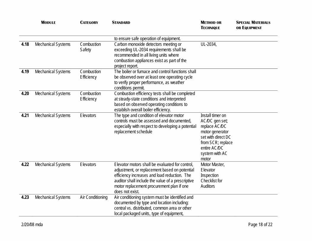
to ensure safe operation of equipment. 4.18 Mechanical Systems Combustion
Safety Carbon monoxide detectors meeting or exceeding UL-2034 requirements shall be recommended in all living units where combustion appliances exist as part of the project report.
UL-2034,
4.19 Mechanical Systems Combustion Efficiency
The boiler or furnace and control functions shall be observed over at least one operating cycle to verify proper performance, as weather conditions permit.
4.20 Mechanical Systems Combustion Efficiency
Combustion efficiency tests shall be completed at steady-state conditions and interpreted based on observed operating conditions to establish overall boiler efficiency.
4.21 Mechanical Systems Elevators The type and condition of elevator motor controls must be assessed and documented, especially with respect to developing a potential replacement schedule
Install timer on AC/DC gen set; replace AC/DC motor generator set with direct DC from SCR; replace entire AC/DC system with AC motor
4.22 Mechanical Systems Elevators Elevator motors shall be evaluated for control, adjustment, or replacement based on potential efficiency increases and load reduction. The auditor shall include the value of a prescriptive motor replacement procurement plan if one does not exist.
Motor Master, Elevator Inspection Checklist for Auditors
4.23 Mechanical Systems Air Conditioning Air conditioning system must be identified and documented by type and location including: central vs. distributed, common area or other local packaged units, type of equipment,

MODULE CATEGORY STANDARD METHOD OR
TECHNIQUE SPECIAL MATERIALS OR EQUIPMENT
2/20/08 mda Page 19 of 22
controls, and operating conditions. 4.24 Mechanical Systems Air Conditioning Central air conditioning ductwork and chiller
pipes must be fully insulated in all parts of the building. Wherever uninsulated pipes or ducts are identified, the project report shall include recommendations for insulation to be installed for energy savings and moisture control.
4.25 Mechanical Systems Air Conditioning For central cooling plants, the auditor shall evaluate by observation and interview: the chilled water and condenser setpoints, pump and cooling tower fan controls, economizer operation.
4.26 Mechanical Systems Air Conditioning Energy improvements and/or replacement of cooling equipment shall be evaluated based on system usage and rated and part-load efficiencies. The replacement of cooling equipment should be considered if necessary or cost-effective. Include equipment selection recommendations for future planned replacements in the project report.
4.27 Mechanical Systems Ventilation An Equipment Schedule shall be created for central and in-unit systems including; fan size and rated capacity, location, and units/areas served where feasible. Assess the adequacy of the ventilation and fan control through interview and observation. Opportunities for fan control scheduling and/or adjustment shall be considered as part of the scope of work. (See also Sections 3.7 to 3.11 for ventilation system diagnostic requirements)
4.28 Mechanical Systems Ventilation Identify all existing ventilation air intakes and document location, size, and determine if intake air source is at risk of contamination from

MODULE CATEGORY STANDARD METHOD OR
TECHNIQUE SPECIAL MATERIALS OR EQUIPMENT
2/20/08 mda Page 20 of 22
pollutant sources (parking garages, combustion sources, refuse areas, etc.). Make recommendations for improvements to placement, location, and/or design of ventilation air intakes to ensure an adequate supply of fresh air to the system.
4.29 Mechanical Systems Ventilation If performance issues with the ventilation system are identified during the course of the completing the required inspections and diagnostic tests, recommend a comprehensive evaluation of the ventilation system to be completed by a qualified technician.
4.30 Mechanical Systems Advanced Technologies
Based on site specific conditions and applicability, advanced and emerging technologies shall be considered for EEM’s.
4.31 Mechanical Systems Fuel Switching All possible cost-effective fuel switching opportunities that do not adversely affect the outdoor environment (i.e. increased pollutant emissions) shall be considered in the building evaluation and report.
4.32 Mechanical Fuel Switching When evaluating electric to gas or oil to gas heating fuel switching opportunities, special emphasis should be placed on condensing gas boilers where feasible.
4.33 Mechanical Fuel Switching When evaluating heating fuel switching the analysis shall include potential impact of tariff rate changes on remaining electrical loads and special care in the disaggregation of loads to be converted from those that will remain.
4.34 Mechanical Fuel Switching In the case of electric-drive central chillers the possibility of gas or steam driven chillers shall be evaluated and recommended in the scope of work if feasible and cost-effective.

MODULE CATEGORY STANDARD METHOD OR
TECHNIQUE SPECIAL MATERIALS OR EQUIPMENT
2/20/08 mda Page 21 of 22
5. Electrical 5.1 Electrical General A schedule of existing lighting, motors, and
major appliances shall be created including energy use, power demand, and/or operating schedules as appropriate. Compare to actual usage and demand as a validity check.
5.2 Electrical Lighting Electrical savings for lighting retrofits in apartments, common areas, and outdoors shall be evaluated and cost-effective recommendations for improvements shall be included in the scope of work.
5.3 Electrical Lighting The applicability and potential savings from energy efficient lighting control strategies shall be evaluated. Existing exterior lighting controls shall be assessed based on interviews and observation.
5.4 Electrical Appliances Electrical savings for appliance replacement shall be evaluated based on equipment age, rating, published test data, and/or sampling on-site testing of energy consumption. Recommendations for cost-effective upgrades shall be included in the scope of work.
5.5 Electrical Motors Motors shall be evaluated for control, adjustment, or replacement based on potential efficiency increases, load reduction, and remaining life based on visual inspection and available records. The auditor shall educate management on the value of a prescriptive motor replacement procurement plan.
5.6 Electrical Metering The existing electric metering configuration (direct, master, or master-submeter) and existing metering equipment (standard,
MODULE CATEGORY STANDARD METHOD OR
TECHNIQUE SPECIAL MATERIALS OR EQUIPMENT
2/20/08 mda Page 22 of 22
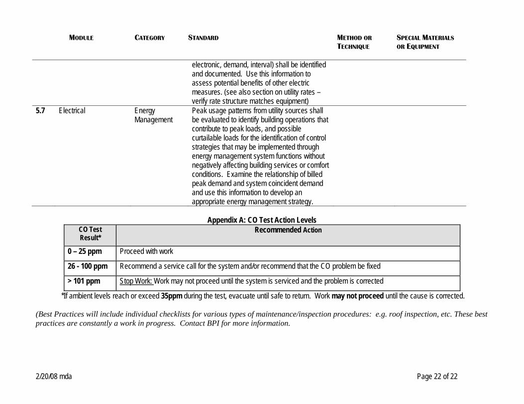
electronic, demand, interval) shall be identified and documented. Use this information to assess potential benefits of other electric measures. (see also section on utility rates – verify rate structure matches equipment)
5.7 Electrical Energy Management
Peak usage patterns from utility sources shall be evaluated to identify building operations that contribute to peak loads, and possible curtailable loads for the identification of control strategies that may be implemented through energy management system functions without negatively affecting building services or comfort conditions. Examine the relationship of billed peak demand and system coincident demand and use this information to develop an appropriate energy management strategy.
Appendix A: CO Test Action Levels
CO Test Result*
Recommended Action
0 – 25 ppm Proceed with work
26 - 100 ppm Recommend a service call for the system and/or recommend that the CO problem be fixed
> 101 ppm Stop Work: Work may not proceed until the system is serviced and the problem is corrected
*If ambient levels reach or exceed 35ppm during the test, evacuate until safe to return. Work may not proceed until the cause is corrected. (Best Practices will include individual checklists for various types of maintenance/inspection procedures: e.g. roof inspection, etc. These best practices are constantly a work in progress. Contact BPI for more information.