technicalnotes nationaladvisory …
TRANSCRIPT

-..1 .
.
..—.J .-,
*
.
8,. . -.=-——.”. >--,
TECHNICAL NOTES
NATIONAL ADVISORY COMkHTTEE FOR AERONAUTZGS.
.
NO. 358
—. . . .
.
EXPERIMENTS WITH A MODEL WATER TUNNEL
By Eastman N. Jacobs and Ira H. AbbottLangley Memorial Aeronautical.Laboratory
.
.-; -. .---
.
.,. .
-“,
Waf3hingtonDeoember, 1930
.
NATIONAL ADVISORY
W.*
COMKITTEE FOR AERONAUTICS—
TECHNICAL-NOTE NO. 358
EXPERIMENTS WITH A MODEL WATER TUNNEL
By Eastman N. Jacobs and Ira H. Abbott
Summa
This report describes a model
by the Nation~ Advisory Committee
rY
water tunnel built in 1928
for Aeron~tics to investi-
gate the -possibilityof using water tunnels for aerodynamic in-
vestigations at large scsles. The model tunnel is similar to
an open-throat wind tunnel, but uses water for the working
fluid. Results are given of tests of the tunnel and also of
some observations made with model airfoils in the tunnel to
● study the phenomena of cavitation. It is concluded that a water
tunnel does not offer a convenient method of making aerodynamic8 .
investigations at large scales. A large water tunnel would be
of value chiefly for use in the study of cavitation.
Introduction
In aerodynamic model testing it is possible to obtain an.—
air flow similar to that at full scale by conducting the tests
at laXge values of the Reynolds Numker. Since the Reynolds Num-
~~ varies directly as the scale of the model (expressedber( v/
by the characteristic length 1), directly .asthe velocity (V),●
and inversely as the kinematic viscosity (~), large values of
●

)N.A.C.A. Technical,Note No. 358 2
1
the Reynolds Nqmber may be obtained by increasing V or decreas–
ing v. In the Variable Density Wind Tunnel of the National
Advisory Committee for Aeronautics (Reference 1), tests are made
in air compressed to 20 atmospheres. The kinematic viscosity
is thus teduced to approximately 1/20 of its norm~ value, and
the Reynolds Number at a given velocity is correspondingly in-
creased. As another means of securing high Reynolds Numbers,
the use of water for the working fluid has been considered. At
normal temperatures the kinematic viscosity of water is between
1/8 and 1/15 that of air, but if the water is heated to a temper-
ature of 90°G, the kinematic viscosity is reduced to l/4~ that
of air at standard conditions.
An investigation of the possibility of using mater for thet
working fluid in conducting aerodynmflictests at large values
. of the Reynolds Number was begun in January, 1928. Some prelim-
inary designs of a water tunnel were made, and later a model—
water tunnel was f!.esignedand constructed. The experimental in-
vestigatio~ was be~ in August, 1928, when tests of the model
tunnel were sts.zted. A number of special problems were encoun-.
tered in connection with the investigation, the most importwt
of which was that of dewing with cavitation. In the qodel tun-
nel, as first constructed, the water was circulated by a propel-
ler, as is customary in wind–tunnel testing. However, it was
found that the water was churned by the propeller, probably be-
cause of cavitation on the blades, until it became milky in ap-

pearwnce. The milky appearance was undoubtedly due to the pres-
ence of a large number of small air bubbles. Since this condi-
tion was considered very undesirable, a specially designed fiver
stage turbine type pump was substituted for the propeller. It
was then possible to keep the water clear until a velocity Was
reached that.was sufficiently high to produce cavitation Qn a
model airfoil placed in the test section at any angle of attack.
A brief investigation was then made on airfoil models mounted in
the completed tunnel to study cavitation.
General Description,.
The model water tunnel of the National Advisory Committee
\for Aeronautics is of the open-throat type with a single return
passage. A jet of water is discharged from a nozzle-shaped en-
trance cone through a glass-enclosed, water-filled test chamber
into a flare-mouthed exit cone. As shown in Figures 1 and 2, a
comparatively large chamber is provided, just @cad of the en-
trance cone, to equalize and stabilize the flow. The cross-
sectional area of this chamber is nine times the area of the
mouth of the entrance cone.
A marine type propeller proved unsatisfactory for circulat:,..
ing the water because of cavitation on the propeller blades, so
a specially designed turbine type pump was substituted. This
pump has five stages to reduce the pressure gain through each

N.A.C.A. Technical Note No. 358 4
set of blades. The pressure distribution through the pump is
shown in Figure 3. Power is supplied through a belt drive by a
variable speed electric motor.
A mercury manometer with water-filled leads is connected
between the test chamber and the laxge chamber ahead of the en-
trance cone to indicate the average dynamic pressure. Another
manometer indicates the static head in the test chamber.
In order to control the temperature of the water, two elec-
trical-resistance heater elements are installed in the largeJ...-
chamber. Since the energy &fifilied{~ circulate the water in-
creases its temperature, provision is made for cooling it by
the introduction of cold wa,ter into the large chamber, the sur-
plus beirigdischarged from the test chamber. By regulation of
the heads on the ingoing and outgting streams the static pres–
sure is controlled.
The diameter of the entrance cone is 2&-inches. Three exit
cones, with different minimum diameters, were tried, and a cone
with a minimum diameter of 2-3/4 inches, or 19 per cent greater
than that of the entrance cone, was-selected as better than
either of the smaller ones. The distance from the mouth of the
entrance cone to the flare of the exit cone is 3-9/16 inches~
NO attempt was made to measure forces on models in this tun-
nel, but a model mounting is provided by means of which airfoil —
* or marine propeller section models with 1~.inch chords can be
mounted in the jet in such a manner as to permit the angle of@.

.
b N.A.C.A. Technical Note No. 358 5
?
,
attack to be changed during operation. The model extends clear
across the jet.
Tests
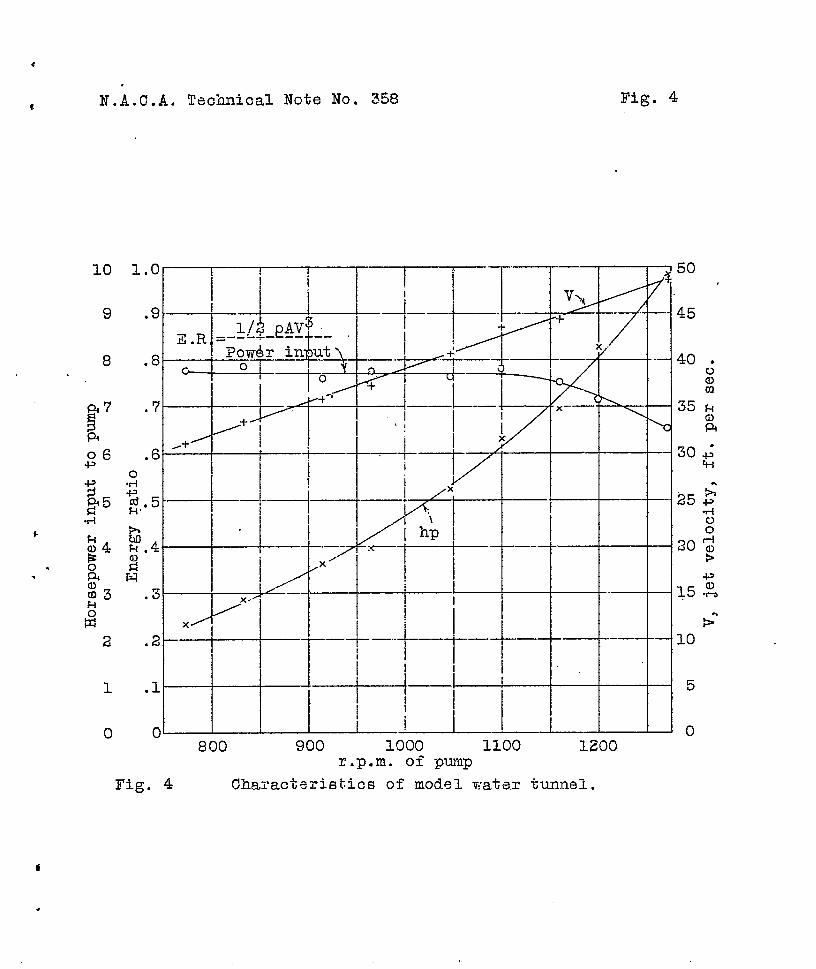
A series of calibration tests were made ofithe water tunnel
to determine its operating characteristics. These tests showed
satisfactory total head distributions across the jet. C~ves of
jet velocity, power consumption and energy ratio were obtained
(Fig. 4).
Velocities up to about 45 feet per second are obtained with–
out excessive power absorption. The energy ratio of the tunnel
alone is approximately ().77throughout most of the operating
range, but decreases at velocities above about 42 feet per sec–
end. This energy ratio is probably somewhat lower than would
be obtained in a lsxger tunnel because of the excessive friction
losses in the”small turbine pump, and because the pump was,too
small to permit accurate forming of the cast bronze blades,
Flow characteristics.- Velocities up to about 45 feet per
second are obtainable without objectionable surges or pulsations.
The flow through the test chamber is marked, however, by lmge
eddies in the water surrounding the jet. These eddies were stud-
ied by means of fine pieces of coal in the water, and their max–
imum velocity was estimated to be about 1/10 to 1/6 that of the●
average jet velocity. At high speeds, these eddies are so pro-
●
● nounced as to cause cavitation at the flare of the exit cone.

N.A.C.A. Technical Note No. 358 6
The model, which extends clesx across the jet, deflects the flow
so that an increased amount of mater is spilled
bottom of the exit cone.
Free surface operation.- The use of a free
a water to free air surface on the test chsmber
the installation, maintenance, and operation of
out around the
surface, that is,
would facilitate
a force balance
and other testing equipment. It would also offer advantages in
photographing
tests. Tests
from the test
is lower than
sequently the
flow formation and in observing the model during
were made, therefore, w“iththe glass top removed
chamber. The water level under these conditions
it would normally be in a tunnel of this type, con-
static pressure in the jet is very small. Several*
runs were made to determine the jet speeds at which the free sur-
,
.
face became noticeably disturbed. With the model set at -6°,*
this speed was found to be 2.2 feet per second. With the.angle
of attack increased to +24°, this velocity increased to 3.6 feet
per second. Runs were also made to determine the speeds at which
the surface entirely broke down and let air bubbles into the exit
cone. This speed was found to be 7.6 feet per second with the
model at an angle of attack of -6°, and 11.0 feet pe’rsecond
with the model at +24°. It is noteworthy that the jet speed
with a free surface can be greater when there is a wing across
the jet. From these tests it is concluded that free surface oP-
eration at reasonably high speeds is practicable only with a much
larger tunnel.
i

.
N.A.C.A. Technical Note
L
Cavitation tests.-
No. 358 7
A Series of comparative cavitation tests
was made by means of visual observation on models of several
marine propeller sections and one airfoil section (a Clark Y
section reduced to a thickness of 19 per cent of the chord).
An attempt was made to correlate the results of these tests with
the results of pressure-distribution tests.
< The visual cavitation tests were made at constant water tem-.
peratuxe and static pressure. The cavitation on the different
models was compared at angles of attack corresponding to certain
computed lift coefficients. At jet speeds above about 30 feet
. per second, cavitation began with the appearance of a small, rap-
idly fluctuating, and occasionally disappearing cavity near the
leading edge
the upper or
tion and the
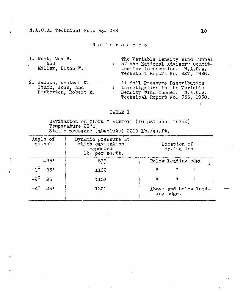
Table I
of the section. The cavity was located on either
lower surface, depending upon the form of the sec-
angle of attack.
gives the conditions under which cavitation first
* appeared on the airfoil. At higher jet speeds the cavity varied.
very rapidly in size but never disappeared. At the highest jet
speeds obtainable, the cavity streamed off the surface of the
section and formed a milky region extending into the exit cone .
(Fig. 5). With the different models there were noticeable dif-
ferences in the jet speeds at which cavitation began, in the ap-
pearance sad location of the cavity, and in the rate at which the
cavitation increased with jet speeds, but these differences were
not so pronounced as to make any section markedly superior in

.
N.A.C.A. Technical Note No. 358 8.
L
these respects.
In order to investigate the locsl conditions under which
cavitation appeared, measurements of the pressures near the point
of formation of the cavity were attempted. The results of these
tests were not satisfactory,
because of the small size of
occur on a very small area.
owing to difficulties encountered
the model. Peak negative pressures
It was impossible to know whether
*
this maximum negative pressure was measured because: only one
orifice could be used at a time, difficulties were encountered
in locating this orifice in this small area, and the smallest
practicable orifice was too large in comparison with the size of
the section. The peak pressures on the airfoil section, however,
were calculated from wind-tunnel tests (Reference 2). The peak
negative pressures on the sharp-nosed marine propeller sections
were too problematic and too sensitive to sm~l changes in ~gle
of attack to allow an estimate of their magnitudes to be made.
Cavitation might be expected to occur when the absolute
local pressure is reduced to the vapor pressure of the water.
The calculations made for the Clark Y airfoil reduced to a thick-
ness of 10 per cent of the chord indicate that the local reduc-
tion in pressure below the static pressure would not exceed
1.2q at the angles of attack used. If this reduction was reached,
visible cavitation beg~ when the pressue reduction was 48 per.
cent of the tot= absolute static pressure minus the vapor pres-
sure of the water. If it were assumed that pressures approach-

.
b N.A.C.A, Technical Note No. 358 9
ing the vapor pressure of the water were reached when visible
_______ ,,. -.. .cavz~a~zon zlrsz Degan, pressure reductions of 2.44q would be
required in the flow, nearly 2* times the dynsmic pressure. This ~
seems hardly possible in the range of angles of attack investi- —
gated, although at the highest speeds at which tests were made,
a local pressure reduction of only 1.29q would be required to
reduce the local.absolute pressure to the vapor pressure of the
water, and this pressure reduction would undoubtedly be reached
on the surface of an airfoil at moderate angles of attack.
These results indicate that visible cavitation probably begins
before the absolute local pressuze is reduced to-the v~or pres-
‘
*
sure of the water because of dissolved air coming out of solu-
tion. 1% is also probab~e that visible cavitation has become
very pronounced before the vapor pressuce of the vater is
reached.
Conclusion
This investigation has led to the conclusion that aerody-
namic tests at high Reynolds Numbers c-not be made ~ conven~
iently by use of a water tunnel as by other methods, but the ex-
periments suggest that such app~atus may be of great v~ue for
investigating the phenomena of cavitation in water.
Langley Me~orisl Aeronautical Laboratory,National Advisory Committee for Aeronautics,
Langley Field, Vs., November 28, 1930.
●
*
N.A.C.A. Technical Note No.
Re
1. Munk, Max M.and
Miller, Elton W.
2. Jacobs, Eastman N.StCLc:z,John, andPinkerton, Robert M.
f
358
er
:
●.
ences
The Variable Density Wind Tunnelof the National Advisory Commit-tee for Aeronautics. N.A.C.A.Technical Report No. 227, 1926.
Airfoil Pressure DistributionInvestigation in the VariableDensity Wind Tunnel. N.A.C.ASTechnical Report No. 353, 1930.
/
TABLE I
Cavitation on Clark Y airfoil (10 per cent thick)Temperature 28°CStatic pressure (absolute) 2200 lb./sq.ft.
Angle ofattack
_351
+1° 25
+20 -25
+40 251
Dynamic pressure’”atwhich cavitation
appearedlb. per sq.ft.
87?
1162
1136
1291
Location ofcavitation
Below
II
II
Aboveing
leading
11
It
11
II
and below lead-edge.

. . . ..’,
* .
Scale of drawing in inches
o 3 6
N. A.C.A. WATER TUNNEL
P-#
?
E~s-Z0
w“E
Fig.1 Model water- tunnel section ~
1~

.>. . . w.
m

N.A.O.A. Techaical Note No. 358
9
id
—,
+
/’/
//’
;
\
Fig. 3
—
-1 .——I
i I
1 I
x I II I 11#
1 2 3 4Pump stages
Pressuze in pump stages.
.—
—.
5
.
.
.
N.A.C.A. Technical Note No. 358 Fig. 4
10 1. .—
—.—
50
,/
—. .i i
459 .
40 ●
:
35 :alQ1
8 .
x–—●
/\
.
.—
.
-++ —-
1
--l —L
—LJ-
102 -—-.
51 —
—
.
001200800 900 1000 1100
r.p.m. of pump
Fig. 4 Characteristics of model wat= tunnel.