technicalspecificationsbetamedical.weebly.com/uploads/8/4/1/6/8416380/technical...ec601-2-75.3...
TRANSCRIPT

35
Technical Specifications
Space RequirementsFor safety reasons, the computer and all peripherals must be in the same room with the scanner.
Lunar PRODIGY, PRODIGY Advance, DPX-Pro, DPX-NT, DPX-MD+ Full size Table
Standard room configuration: The computer and peripherals must be located more than 1.83 m from the scanner.Recommended room dimensions are: 3.7 meters x 3.7 meters (12 feet x 12 feet)
Small room configuration: Room dimensions must be at least 3.0 m x 2.4 m if the computer and peripherals are powered by anisolation transformer. Equipment powered by an isolation transformer can be located anywhere in the room with the scanner. Theisolation transformer and scanner must be plugged into the same dedicated line outlet.
Lunar PRODIGY system no. DF+11999 and lower
Scanner power output configuration: It is recommended that the computer and all peripherals be powered by the scanner(scanner power output). If scanner power output is used, the computer and peripherals can be placed anywhere in the room. Roomdimensions must be at least 3.0 m x 2.4 m.
Lunar PRODIGY, PRODIGY Advance, DPX-Pro, DPX-NT, DPX-MD+, Compact Tableand DPX Bravo Tables
Standard room configuration: The computer and all peripherals must be located more than 1.83 m from the scanner.Recommended room dimensions are 2.3 meters x 3.7 meters (7.5 feet x 12 feet).
Small room configuration: Room dimensions must be at least 2.3 m x 2.4 m (7.5 feet x 8 feet) if the computer and peripherals arepowered by an isolation transformer. Equipment powered by an isolation transformer can be located anywhere in the room with thescanner. The isolation transformer and scanner must be plugged into the same dedicated line outlet.
Lunar DPX Duo Table
Standard room configuration: The computer and all peripherals must be located more than 1.83 m from the scanner.Recommended room dimensions are 2.3 meters x 3.7 meters (7.5 feet x 12 feet).
Small room configuration: Room dimensions must be at least 2.4 m x 2.8 m (8 feet x 9 feet) if the computer and peripherals arepowered by an isolation transformer. Equipment powered by an isolation transformer can be located anywhere in the room with thescanner. The isolation transformer and scanner must be plugged into the same dedicated line outlet.

Table Of Contents
36
Component SpecificationsSpecifications for standard components shipped with the system.
Component SpecificationsLunar PRODIGYAdvanceScanner table*
Full Size Table
Compact Table
Maximum patient weight supported: 159 kg (350 pounds)
Dimensions: 262.3 cm x 109.3 cm x 128.3 cm (W x D x H)Weight: approximately 272.16 kg
Dimensions: 201 cm x 109.3 cm x 128.3 cm (W x D x H)Weight: approximately 254 kg
Lunar PRODIGYScanner table*
Full Size Table
Compact Table
Maximum patient weight supported: 136 kg (300 pounds)
Dimensions: 262.3 cm x 109.3 cm x 128.3 cm (W x D x H)Weight: approximately 272.16 kg
Dimensions: 201 cm x 109.3 cm x 128.3 cm (W x D x H)Weight: approximately 254 kg
Lunar DPX-NTPro/MD+Scanner table*
Full-size table
Compact table
DPX Duo
DPX Bravo
Maximum patient weight supported: 136 kg (300 pounds)
Dimensions: 242 cm x 103 cm x 128 cm (W x D x H)Weight: approximately 272kgMaximum patient weight supported: 136 kg
Dimensions: 181 cm x 103 cm x 128 cm (W x D x H)Weight: approximately 254kgMaximum patient weight supported: 136 kg
Dimensions: 186 cm x 86 cm x 147 cm (W x D x H)Weight: approximately 273 kg
Dimensions: 186 cm x 86 cm x 130 cm (W x D x H)Weight: approximately 250 kg
Console table 78.5 cm x 63.3 cm x 48.1 cmComputer Greater than 900Mhz Pentium
512 MB RAMGreater than 10GB hard disk17" SVGA monitor (1024x768x32-bit color)ZIP 250 driveCD ROMAudio capable with speakersModemWindows® XP Professional operating systemInternet Explorer version 5.0Fast Serial I/O board (GE MEDICAL SYSTEMS part number 7151) - Prodigyonly
Printer HP DeskJet 2280 or equivalentW x D x H-44.0 x 40.0 x 19.6 cm
*Depth is measured from the front edge of the scanner table to the back edge of the scanner arm. Height is measured from the topof the scanner arm to the bottom of the scanner arm.
Technical Specifications
37
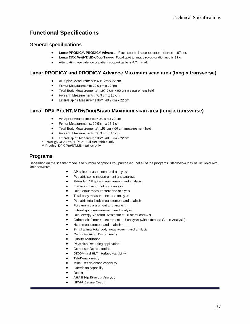
Functional Specifications
General specifications
· Lunar PRODIGY, PRODIGY Advance: Focal spot to image receptor distance is 67 cm.
· Lunar DPX-Pro/NT/MD+/Duo/Bravo: Focal spot to image receptor distance is 58 cm.
· Attenuation equivalence of patient support table is 0.7 mm Al.
Lunar PRODIGY and PRODIGY Advance Maximum scan area (long x transverse)
· AP Spine Measurements: 40.9 cm x 22 cm
· Femur Measurements: 20.9 cm x 18 cm
· Total Body Measurements*: 197.5 cm x 60 cm measurement field
· Forearm Measurements: 40.9 cm x 10 cm
· Lateral Spine Measurements**: 40.9 cm x 22 cm
Lunar DPX-Pro/NT/MD+/Duo/Bravo Maximum scan area (long x transverse)
· AP Spine Measurements: 40.9 cm x 22 cm
· Femur Measurements: 20.9 cm x 17.9 cm
· Total Body Measurements*: 195 cm x 60 cm measurement field
· Forearm Measurements: 40.9 cm x 10 cm
· Lateral Spine Measurements**: 40.9 cm x 22 cm* Prodigy, DPX-Pro/NT/MD+ Full size tables only** Prodigy, DPX-Pro/NT/MD+ tables only
ProgramsDepending on the scanner model and number of options you purchased, not all of the programs listed below may be included withyour software:
· AP spine measurement and analysis
· Pediatric spine measurement and analysis
· Extended AP spine measurement and analysis
· Femur measurement and analysis
· DualFemur measurement and analysis
· Total body measurement and analysis.
· Pediatric total body measurement and analysis
· Forearm measurement and analysis
· Lateral spine measurement and analysis
· Dual-energy Vertebral Assessment: (Lateral and AP)
· Orthopedic femur measurement and analysis (with extended Gruen Analysis)
· Hand measurement and analysis
· Small animal total body measurement and analysis
· Computer Aided Densitometry
· Quality Assurance
· Physician Reporting application
· Composer Data reporting
· DICOM and HL7 interface capability
· TeleDensitometry
· Multi-user database capability
· OneVision capability
· Dexter
· AHA II Hip Strength Analysis
· HIPAA Secure Report

Table Of Contents
38
Environmental Specifications
Operational Environment
Adhere to the specifications that follow during scanner operation:
· Ambient Space (Interior Subcomponents) - For scanner operation and servicing, do not block the areaaround the scanner table. Make sure there is a minimum clearance of 30.5 cm at the head and foot ends of thescanner table, at least 15.2 cm for the arm side, and 45.7 cm for the operator side.
· Ambient Space (Ventilation) - Do not block the cooling vents on the computer and scanner table. Make surethere is 15.2 cm from the console table to the wall for cable clearance and computer plugs.
· Dust, Fumes and Debris - Install the system in a clean, ventilated area. Dust and other airborne debris cancause the diskette drive heads and other sensitive mechanical components to malfunction. GE MEDICALSYSTEMS recommends that you do not smoke in the scanner room.
· Humidity - Make sure the humidity for the scanner area is 20%-80%, non-condensing.
· Power Consumption - The scanner requires a dedicated 100-240 VAC - 20A 100-120 VAC, 10A 220-240 VACcircuit, (single duplex outlet) with isolated ground. The outlet should be located behind the Host PC. The LunarPRODIGY and PRODIGY Advance scanner will draw 40 watts when idle and approximately 450 watts during apatient scan (76kV / 3mA). The Lunar DPX-Pro/NT/MD+ scanner will draw approximately 25 watts when idleand 250 watts during a patient scan (76 Kv / 1.5mA). The Lunar DPX Duo or DPX Bravo scanner will draw 40watts when idle and approximately 450 watts during a patient scan (76kV / 1.5mA). The Host PC (typical PCwith a 17" monitor) will draw approximately 110 watts when powered on.
· Heat Output - The Lunar PRODIGY and PRODIGY Advance scanner will output 150 BTU per hour when idleand 1500 BTU per hour when actively scanning. The Lunar DPX-Pro/NT/MD+/Duo/Bravo scanner will output 90BTU per hour when idle and approximately 900 BTU per hour when actively scanning. The Host PC (PC with17" monitor) will output approximately 400 BTU per hour when powered on.
· Static Electricity - Install and operate the system in a static-free area. Adhere to minimum humidityrequirements to prevent malfunctions caused by static electricity.
· Shock and Vibration - Make sure the scanner table does not receive shock greater than 1G for more than 1millisecond. Make sure the scanner table does not receive vibrations greater than 0.25 G at 5 Hz.
· Temperature - Make sure the temperature during system operation is 65°F-81°F (18°C-27°C).
NOTE: When the system is turned off, or there is a power failure, you must turn the system on and let it warm for one hour.After one hour, complete a Quality Assurance procedure.
Storage and transport environment
Adhere to the specifications that follow for scanner storage and transportation:
· Humidity, 0% to 95% non-condensing.
· Atmospheric pressure, 500 to 1060 hPa.
· Temperature, -40° to 70° C.

Technical Specifications
39
Power Specifications
Leakage current
Computer and peripherals with Isolation Transformer: <100 microamperes.
Scanner Table alone: <500 microamperes.
Scanner input power
Lunar PRODIGY Advance, PRODIGY systems no. DF+12000 and higher, DPX-Pro/NT/MD+ systemsno. 72000 and higher or 90000 and higher, DPX Duo, DPX Bravo
The scanner has a rated input of 100-240 VAC (100-120 for US, Canada). Voltage may fluctuate ±10% from the rated input withouta loss of scanner performance. The input power must meet IEEE 519-1992 for power quality and total harmonic distortion (THD<5%).
Lunar PRODIGY systems no. DF+11999 and lower, DPX-Pro/NT/MD+ systems number 70000-71999
The scanner has 4 different nominal inputs: 100, 115, 230, and 240 VAC. During installation, the scanner is configured for thenominal input which best matches the voltage on site. Voltage may fluctuate ±10% from the nominal value without a loss of scannerperformance. The nominal input (range of inputs) can be found on the system label. The input power must meet IEEE 519-1992 forpower quality and total harmonic distortion (THD <5%).
Scanner output power
Lunar PRODIGY systems no. DF+11999 and lower, DPX-Pro/NT/MD+ systems number 70000-71999
The scanner has 3 different nominal outputs: 100, 120, 240 VAC. The nominal voltage output of the scanner is shown on thesystem label. The computer and all peripherals which use the scanner output power must be rated for this voltage. The maximumpower output is 400 VA.

Table Of Contents
40
X-Ray Generator Specifications
Lunar PRODIGY Advance and PRODIGY X-Ray Generator
PRODIGY Advance, PRODIGY DF+12000 and higher
Lunar PRODIGY Advance, PRODIGY X-ray generator technical information:
Classification Class I Equipment IEC 601-2-7 5.1Degree of protection against electricalshock
Type B equipment IEC 601-2-7 5.2
Protection against ingress of liquids Ordinary medical electricalequipment
IEC 601-2-7 5.3
Connection to supply mains Power supply cord IEC 601-2-7 6.1g)Mode of operation Continuous IEC 601-2-7 6.1m)Maximum X-ray tube voltage 76 kV IEC 601-2-7 6.1m)Maximum X-ray tube current 3 mA IEC 601-2-7 6.1m)Rated mains voltage 100-240 VAC IEC 601-2-7 6.1j)1Number of phases in mains 1 IEC 601-2-7 6.1j)2Mains frequency 50/60 Hertz IEC 601-2-7 6.1j)3Required over-current releases 15 Amp dedicated service IEC 601-2-7 6.1j)5Heat dissipative components X-ray tube dissipates 243W max.
into surrounding air through forcedair convection. Flow rate: 36 m3/h(approx.) Temp. rise of air stream25° C (approx.)
IEC 601-2-7 6.1t)
Allowable high voltage supplies Spellman SBD40PN280X2890 orBertan 2907.
IEC 601-2-7 6.8.1 and50.2.101-102
Allowable tube head assemblies GE MEDICAL SYSTEMS model8743 or equivalent
IEC 601-2-7 6.8.1 and50.2.101-102
Original language of accompanyingdocuments
English IEC 601-2-7, IEC 601-2-28, IEC 601-2-32, 6.8.1
Maximum continuous kV, mA atnominal rated kV
76 kV, 3 mA IEC 601-2-7 6.8.2 1)
Maximum intermittent kV, mA atnominal rated kV
76 kV, 3 mA IEC 601-2-7 6.8.2 1)
Maximum continuous kV, mA atmaximum mA
76 kV, 3 mA IEC 601-2-7 6.8.2 2)
Maximum intermittent kV, mA atmaximum mA
76 kV, 3 mA IEC 601-2-7 6.8.2 2)
Continuous kV, mA for maximumelectric output power
76 kV, 3 mA IEC 601-2-7 6.8.2 3)
Intermittent kV, mA for maximumelectric output power
76 kV, 3 mA IEC 601-2-7 6.8.2 3)
Nominal electric power 0.243 kW IEC 601-2-7 6.8.2 4)Lowest current time product 0.20 mAs. Parameters: 76 kV, 0.10
mA, 2 seconds.IEC 601-2-7 6.8.2 5)
Nominal shortest irradiation times 2 seconds. IEC 601-2-7 6.8.2 6)Method of x-ray tube voltagemeasurement
Voltage divider in high voltage powersupply.
IEC 601-2-7 50.106.1
Method of x-ray tube currentmeasurement
Shunt resistor in high voltage supplyreturn line.
IEC 601-2-7 50.106.2
X-ray tube assembly reference axis Line normal to the tube port,centered on tube port as shown inreference axis figure. Refer to Figure7
IEC 336
Reference loading conditions 8.21 x 10⁵ Joules, 3 mA, 76 kV for 1hour.
IEC 601-1-3 29.204.2
Focal spot to Image Receptor distance 67 cm IEC 601-1-3 29.203.2Attenuation equivalence of patientsupport table.
0.7 mm Al IEC 601-1-3 29.206.2
Technical Specifications
41
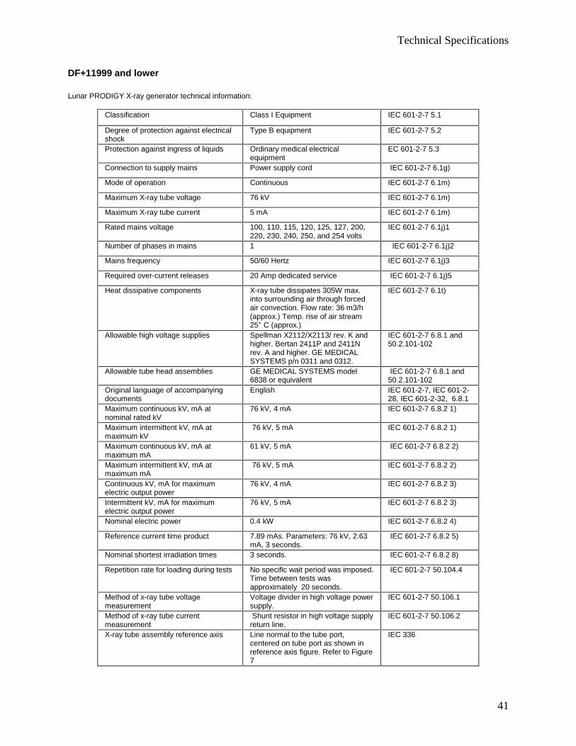
DF+11999 and lower
Lunar PRODIGY X-ray generator technical information:
Classification Class I Equipment IEC 601-2-7 5.1
Degree of protection against electricalshock
Type B equipment IEC 601-2-7 5.2
Protection against ingress of liquids Ordinary medical electricalequipment
EC 601-2-7 5.3
Connection to supply mains Power supply cord IEC 601-2-7 6.1g)
Mode of operation Continuous IEC 601-2-7 6.1m)
Maximum X-ray tube voltage 76 kV IEC 601-2-7 6.1m)
Maximum X-ray tube current 5 mA IEC 601-2-7 6.1m)
Rated mains voltage 100, 110, 115, 120, 125, 127, 200,220, 230, 240, 250, and 254 volts
IEC 601-2-7 6.1j)1
Number of phases in mains 1 IEC 601-2-7 6.1j)2
Mains frequency 50/60 Hertz IEC 601-2-7 6.1j)3
Required over-current releases 20 Amp dedicated service IEC 601-2-7 6.1j)5
Heat dissipative components X-ray tube dissipates 305W max.into surrounding air through forcedair convection. Flow rate: 36 m3/h(approx.) Temp. rise of air stream25° C (approx.)
IEC 601-2-7 6.1t)
Allowable high voltage supplies Spellman X2112/X2113/ rev. K andhigher. Bertan 2411P and 2411Nrev. A and higher. GE MEDICALSYSTEMS p/n 0311 and 0312.
IEC 601-2-7 6.8.1 and50.2.101-102
Allowable tube head assemblies GE MEDICAL SYSTEMS model6838 or equivalent
IEC 601-2-7 6.8.1 and50.2.101-102
Original language of accompanyingdocuments
English IEC 601-2-7, IEC 601-2-28, IEC 601-2-32, 6.8.1
Maximum continuous kV, mA atnominal rated kV
76 kV, 4 mA IEC 601-2-7 6.8.2 1)
Maximum intermittent kV, mA atmaximum kV
76 kV, 5 mA IEC 601-2-7 6.8.2 1)
Maximum continuous kV, mA atmaximum mA
61 kV, 5 mA IEC 601-2-7 6.8.2 2)
Maximum intermittent kV, mA atmaximum mA
76 kV, 5 mA IEC 601-2-7 6.8.2 2)
Continuous kV, mA for maximumelectric output power
76 kV, 4 mA IEC 601-2-7 6.8.2 3)
Intermittent kV, mA for maximumelectric output power
76 kV, 5 mA IEC 601-2-7 6.8.2 3)
Nominal electric power 0.4 kW IEC 601-2-7 6.8.2 4)
Reference current time product 7.89 mAs. Parameters: 76 kV, 2.63mA, 3 seconds.
IEC 601-2-7 6.8.2 5)
Nominal shortest irradiation times 3 seconds. IEC 601-2-7 6.8.2 8)
Repetition rate for loading during tests No specific wait period was imposed.Time between tests wasapproximately 20 seconds.
IEC 601-2-7 50.104.4
Method of x-ray tube voltagemeasurement
Voltage divider in high voltage powersupply.
IEC 601-2-7 50.106.1
Method of x-ray tube currentmeasurement
Shunt resistor in high voltage supplyreturn line.
IEC 601-2-7 50.106.2
X-ray tube assembly reference axis Line normal to the tube port,centered on tube port as shown inreference axis figure. Refer to Figure7
IEC 336
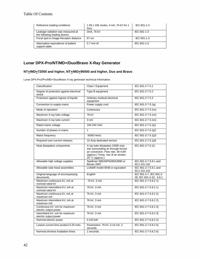
Table Of Contents
42
Reference loading conditions 1.09 x 10⁶ Joules, 4 mA, 76 kV for 1hour.
IEC 601-1-3
Leakage radiation was measured atthe following loading factors.
3mA, 76 kV IEC 601-1-3
Focal spot to Image Receptor distance 67 cm IEC 601-1-3
Attenuation equivalence of patientsupport table.
0.7 mm Al IEC 601-1-3
Lunar DPX-Pro/NT/MD+/Duo/Bravo X-Ray Generator
NT+/MD+72000 and higher, NT+/MD+90000 and higher, Duo and Bravo
Lunar DPX-Pro//Pro/MD+/Duo/Bravo X-ray generator technical information:
Classification Class I Equipment IEC 601-2-7 5.1
Degree of protection against electricalshock
Type B equipment IEC 601-2-7 5.2
Protection against ingress of liquids Ordinary medical electricalequipment
IEC 601-2-7 5.3
Connection to supply mains Power supply cord IEC 601-2-7 6.1g)
Mode of operation Continuous IEC 601-2-7 6.1m)
Maximum X-ray tube voltage 76 kV IEC 601-2-7 6.1m)
Maximum X-ray tube current 3 mA IEC 601-2-7 6.1m)
Rated mains voltage 100-240 VAC IEC 601-2-7 6.1j)1
Number of phases in mains 1 IEC 601-2-7 6.1j)2
Mains frequency 50/60 Hertz IEC 601-2-7 6.1j)3
Required over-current releases 15 Amp dedicated service IEC 601-2-7 6.1j)5
Heat dissipative components X-ray tube dissipates 243W max.into surrounding air through forcedair convection. Flow rate: 36 m3/h(approx.) Temp. rise of air stream25° C (approx.)
IEC 601-2-7 6.1t)
Allowable high voltage supplies Spellman SBD40PN280X2890 orBertan 2907.
IEC 601-2-7 6.8.1 and50.2.101-102
Allowable tube head assemblies LUNAR model 8548 or equivalent IEC 601-2-7 6.8.1 and50.2.101-102
Original language of accompanyingdocuments
English IEC 601-2-7, IEC 601-2-28, IEC 601-2-32, 6.8.1
Maximum continuous kV, mA atnominal rated kV
76 kV, 3 mA IEC 601-2-7 6.8.2 1)
Maximum intermittent kV, mA atnominal rated kV
76 kV, 3 mA IEC 601-2-7 6.8.2 1)
Maximum continuous kV, mA atmaximum mA
76 kV, 3 mA IEC 601-2-7 6.8.2 2)
Maximum intermittent kV, mA atmaximum mA
76 kV, 3 mA IEC 601-2-7 6.8.2 2)
Continuous kV, mA for maximumelectric output power
76 kV, 3 mA IEC 601-2-7 6.8.2 3)
Intermittent kV, mA for maximumelectric output power
76 kV, 3 mA IEC 601-2-7 6.8.2 3)
Nominal electric power 0.243 kW IEC 601-2-7 6.8.2 4)
Lowest current time product 0.20 mAs. Parameters: 76 kV, 0.10 mA, 2seconds.
IEC 601-2-7 6.8.2 5)
Nominal shortest irradiation times 2 seconds. IEC 601-2-7 6.8.2 6)
Technical Specifications
43
Method of x-ray tube voltagemeasurement
Voltage divider in high voltage powersupply.
IEC 601-2-7 50.106.1
Method of x-ray tube currentmeasurement
Shunt resistor in high voltage supplyreturn line.
IEC 601-2-7 50.106.2
X-ray tube assembly reference axis Line normal to the tube port,centered on tube port as shown inreference axis figure. Refer to Figure7
IEC 336
Reference loading conditions 8.21 x 10⁵ Joules, 3 mA, 76 kV for 1hour.
IEC 601-1-3 29.204.2
Focal spot to Image Receptor distance 58 cm IEC 601-1-3 29.203.2
Attenuation equivalence of patientsupport table.
0.7 mm Al IEC 601-1-3 29.206.2
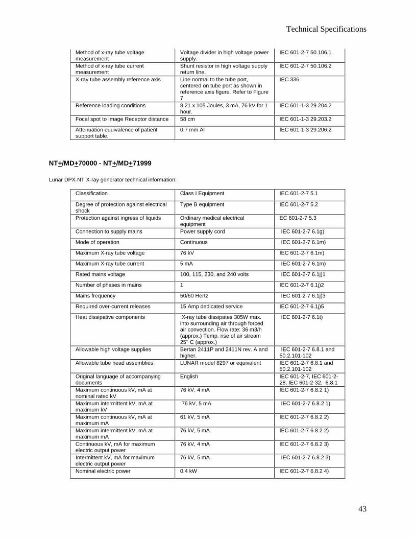
NT+/MD+70000 - NT+/MD+71999
Lunar DPX-NT X-ray generator technical information:
Classification Class I Equipment IEC 601-2-7 5.1
Degree of protection against electricalshock
Type B equipment IEC 601-2-7 5.2
Protection against ingress of liquids Ordinary medical electricalequipment
EC 601-2-7 5.3
Connection to supply mains Power supply cord IEC 601-2-7 6.1g)
Mode of operation Continuous IEC 601-2-7 6.1m)
Maximum X-ray tube voltage 76 kV IEC 601-2-7 6.1m)
Maximum X-ray tube current 5 mA IEC 601-2-7 6.1m)
Rated mains voltage 100, 115, 230, and 240 volts IEC 601-2-7 6.1j)1
Number of phases in mains 1 IEC 601-2-7 6.1j)2
Mains frequency 50/60 Hertz IEC 601-2-7 6.1j)3
Required over-current releases 15 Amp dedicated service IEC 601-2-7 6.1j)5
Heat dissipative components X-ray tube dissipates 305W max.into surrounding air through forcedair convection. Flow rate: 36 m3/h(approx.) Temp. rise of air stream25° C (approx.)
IEC 601-2-7 6.1t)
Allowable high voltage supplies Bertan 2411P and 2411N rev. A andhigher.
IEC 601-2-7 6.8.1 and50.2.101-102
Allowable tube head assemblies LUNAR model 8297 or equivalent IEC 601-2-7 6.8.1 and50.2.101-102
Original language of accompanyingdocuments
English IEC 601-2-7, IEC 601-2-28, IEC 601-2-32, 6.8.1
Maximum continuous kV, mA atnominal rated kV
76 kV, 4 mA IEC 601-2-7 6.8.2 1)
Maximum intermittent kV, mA atmaximum kV
76 kV, 5 mA IEC 601-2-7 6.8.2 1)
Maximum continuous kV, mA atmaximum mA
61 kV, 5 mA IEC 601-2-7 6.8.2 2)
Maximum intermittent kV, mA atmaximum mA
76 kV, 5 mA IEC 601-2-7 6.8.2 2)
Continuous kV, mA for maximumelectric output power
76 kV, 4 mA IEC 601-2-7 6.8.2 3)
Intermittent kV, mA for maximumelectric output power
76 kV, 5 mA IEC 601-2-7 6.8.2 3)
Nominal electric power 0.4 kW IEC 601-2-7 6.8.2 4)
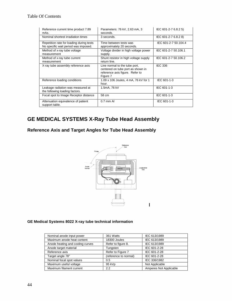
Table Of Contents
44
Reference current time product 7.89mAs.
Parameters: 76 kV, 2.63 mA, 3seconds.
IEC 601-2-7 6.8.2 5)
Nominal shortest irradiation times 3 seconds. IEC 601-2-7 6.8.2 8)
Repetition rate for loading during testsNo specific wait period was imposed.
Time between tests wasapproximately 20 seconds.
IEC 601-2-7 50.104.4
Method of x-ray tube voltagemeasurement
Voltage divider in high voltage powersupply.
IEC 601-2-7 50.106.1
Method of x-ray tube currentmeasurement
Shunt resistor in high voltage supplyreturn line.
IEC 601-2-7 50.106.2
X-ray tube assembly reference axis Line normal to the tube port,centered on tube port as shown inreference axis figure. Refer toFigure 7
IEC 336
Reference loading conditions 1.09 x 10⁶ Joules, 4 mA, 76 kV for 1hour.
IEC 601-1-3
Leakage radiation was measured atthe following loading factors.
1.5mA, 76 kV IEC 601-1-3
Focal spot to Image Receptor distance 58 cm IEC 601-1-3
Attenuation equivalence of patientsupport table.
0.7 mm Al IEC 601-1-3
GE MEDICAL SYSTEMS X-Ray Tube Head Assembly
Reference Axis and Target Angles for Tube Head Assembly
GE Medical Systems 8022 X-ray tube technical information
Nominal anode input power 361 Watts IEC 613/1989Maximum anode heat content 18300 Joules IEC 613/1989Anode heating and cooling curves Refer to figure 8. IEC 613/1989Anode target material Tungsten IEC 601-2-28Reference axis Refer to Figure 7 IEC 601-2-28Target angle 78° (reference to normal) IEC 601-2-28Nominal focal spot values 0.5 IEC 336/1982Maximum useful voltage 95 kVp Not ApplicableMaximum filament current 2.2 Amperes Not Applicable

Technical Specifications
45
GE Medical Systems 8743 X-ray tube technical information (DF+12000 and higher)
Beam filtration is permanently fixed with a minimum 2.9 mm Aluminum-equivalent.
Inherent filtration >2.9 mm Al/70 kV IEC 522/1976Filament characteristics Refer to Figure 9 IEC 613/1989Nominal x-ray tube voltage 76 kV - Anode to Cathode
38 kV - Anode to Earth38 kV - Cathode to Earth
IEC 613/1989
Single load rating 228 W (3 mA, 76 kV) for up to 15 min. IEC 613/1989Serial load rating 228 W (3 mA, 76 kV) for up to 15 min. IEC 613/1989Maximum x-ray tube assembly heatcontent
260 kJoules IEC 613/1989
X-ray tube assembly heating andcooling curves
Refer to Figure 10 IEC 613/1989
Maximum continuous heatdissipation
243 Watts (3mA x 76kV + 15W filament) IEC 613/1989
Maximum symmetrical radiationfield
3.5 mm/19.4 mm at a distance from the focalspot of 220 mm.
IEC 806/1984
Dimensions 17 cm x 19.4 cm x 11 cm IEC 601-2-28Weight 8.6 kg IEC 601-2-28
GE Medical Systems 6838 X-ray tube technical information (DF+11999 and lower)
Beam filtration is permanently fixed with a minimum 2.9 mm Aluminum-equivalent.NOTE: Beam quality has a minimum first half-value layer of 3.2 mm of Al at 76 kV.
Inherent filtration >2.9 mm Al/70 kV IEC 522/1976Filament characteristics Refer to Figure 9 IEC 613/1989Nominal x-ray tube voltage 76 kV - Anode to Cathode
38 kV - Anode to Earth38 kV - Cathode to Earth
IEC 613/1989
Single load rating 361 W (3.00 mA, 76 kV) for up to 4 min., 59 sec. IEC 613/1989Serial load rating 361 W (3.00 mA, 76 kV) for up to 4 min., 59 sec. IEC 613/1989Maximum x-ray tube assembly heatcontent
260 kJoules IEC 613/1989
X-ray tube assembly heating andcooling curves
Refer to Figure 10 IEC 613/1989
Maximum continuous heatdissipation
361 Watts IEC 613/1989
Maximum symmetrical radiationfield
3.5 mm/19.4 mm at a distance from the focal spot of 220mm.
IEC 806/1984
Dimensions 17 cm x 19.4 cm x 11 cm IEC 601-2-28Weight 8.6 kg IEC 601-2-28
GE Medical Systems 8548 X-ray tube technical information (DPX-Pro/NT/MD+ 72000 and higher,DPX Duo, DPX Bravo)
Beam filtration is permanently fixed with a minimum 3.0 mm Aluminum-equivalent.
Inherent filtration >3.0 mm Al/70 kV IEC 522/1976Filament characteristics Refer to Figure 9 IEC 613/1989Nominal x-ray tube voltage 76 kV - Anode to Cathode
38 kV - Anode to Earth38 kV - Cathode to Earth
IEC 613/1989
Single load rating 228 W (3 mA, 76 kV) for up to 15 min. IEC 613/1989
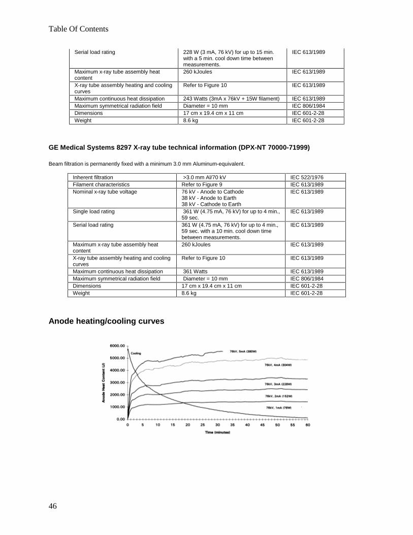
Table Of Contents
46
Serial load rating 228 W (3 mA, 76 kV) for up to 15 min.with a 5 min. cool down time betweenmeasurements.
IEC 613/1989
Maximum x-ray tube assembly heatcontent
260 kJoules IEC 613/1989
X-ray tube assembly heating and coolingcurves
Refer to Figure 10 IEC 613/1989
Maximum continuous heat dissipation 243 Watts (3mA x 76kV + 15W filament) IEC 613/1989Maximum symmetrical radiation field Diameter = 10 mm IEC 806/1984Dimensions 17 cm x 19.4 cm x 11 cm IEC 601-2-28Weight 8.6 kg IEC 601-2-28
GE Medical Systems 8297 X-ray tube technical information (DPX-NT 70000-71999)
Beam filtration is permanently fixed with a minimum 3.0 mm Aluminum-equivalent.
Inherent filtration >3.0 mm Al/70 kV IEC 522/1976Filament characteristics Refer to Figure 9 IEC 613/1989Nominal x-ray tube voltage 76 kV - Anode to Cathode
38 kV - Anode to Earth38 kV - Cathode to Earth
IEC 613/1989
Single load rating 361 W (4.75 mA, 76 kV) for up to 4 min.,59 sec.
IEC 613/1989
Serial load rating 361 W (4.75 mA, 76 kV) for up to 4 min.,59 sec. with a 10 min. cool down timebetween measurements.
IEC 613/1989
Maximum x-ray tube assembly heatcontent
260 kJoules IEC 613/1989
X-ray tube assembly heating and coolingcurves
Refer to Figure 10 IEC 613/1989
Maximum continuous heat dissipation 361 Watts IEC 613/1989Maximum symmetrical radiation field Diameter = 10 mm IEC 806/1984Dimensions 17 cm x 19.4 cm x 11 cm IEC 601-2-28Weight 8.6 kg IEC 601-2-28
Anode heating/cooling curves

Technical Specifications
47
Cathode emission characteristics
X-ray tube assembly heating/cooling curves
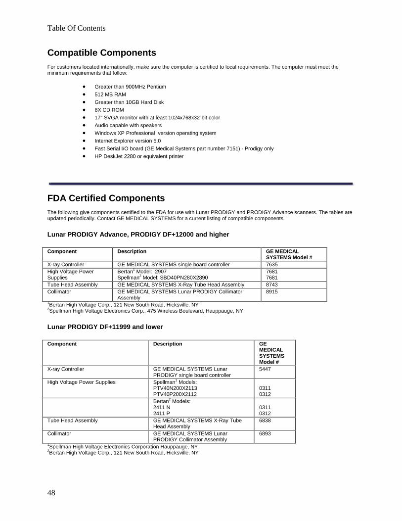
Table Of Contents
48
Compatible ComponentsFor customers located internationally, make sure the computer is certified to local requirements. The computer must meet theminimum requirements that follow:
· Greater than 900MHz Pentium
· 512 MB RAM
· Greater than 10GB Hard Disk
· 8X CD ROM
· 17" SVGA monitor with at least 1024x768x32-bit color
· Audio capable with speakers
· Windows XP Professional version operating system
· Internet Explorer version 5.0
· Fast Serial I/O board (GE Medical Systems part number 7151) - Prodigy only
· HP DeskJet 2280 or equivalent printer
FDA Certified ComponentsThe following give components certified to the FDA for use with Lunar PRODIGY and PRODIGY Advance scanners. The tables areupdated periodically. Contact GE MEDICAL SYSTEMS for a current listing of compatible components.
Lunar PRODIGY Advance, PRODIGY DF+12000 and higher
Component Description GE MEDICALSYSTEMS Model #
X-ray Controller GE MEDICAL SYSTEMS single board controller 7635High Voltage PowerSupplies
Bertan1 Model: 2907Spellman2 Model: SBD40PN280X2890
76817681
Tube Head Assembly GE MEDICAL SYSTEMS X-Ray Tube Head Assembly 8743Collimator GE MEDICAL SYSTEMS Lunar PRODIGY Collimator
Assembly8915
1Bertan High Voltage Corp., 121 New South Road, Hicksville, NY2Spellman High Voltage Electronics Corp., 475 Wireless Boulevard, Hauppauge, NY
Lunar PRODIGY DF+11999 and lower
Component Description GEMEDICALSYSTEMSModel #
X-ray Controller GE MEDICAL SYSTEMS LunarPRODIGY single board controller
5447
High Voltage Power Supplies Spellman1 Models:PTV40N200X2113PTV40P200X2112
03110312
Bertan2 Models:2411 N2411 P
03110312
Tube Head Assembly GE MEDICAL SYSTEMS X-Ray TubeHead Assembly
6838
Collimator GE MEDICAL SYSTEMS LunarPRODIGY Collimator Assembly
6893
1Spellman High Voltage Electronics Corporation Hauppauge, NY2Bertan High Voltage Corp., 121 New South Road, Hicksville, NY
Technical Specifications
49
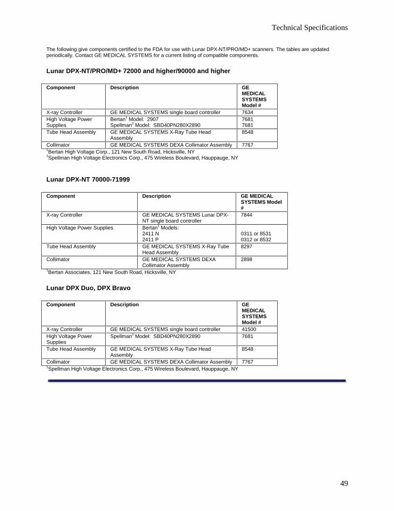
The following give components certified to the FDA for use with Lunar DPX-NT/PRO/MD+ scanners. The tables are updatedperiodically. Contact GE MEDICAL SYSTEMS for a current listing of compatible components.
Lunar DPX-NT/PRO/MD+ 72000 and higher/90000 and higher
Component Description GEMEDICALSYSTEMSModel #
X-ray Controller GE MEDICAL SYSTEMS single board controller 7634High Voltage PowerSupplies
Bertan1 Model: 2907Spellman2 Model: SBD40PN280X2890
76817681
Tube Head Assembly GE MEDICAL SYSTEMS X-Ray Tube HeadAssembly
8548
Collimator GE MEDICAL SYSTEMS DEXA Collimator Assembly 77671Bertan High Voltage Corp., 121 New South Road, Hicksville, NY2Spellman High Voltage Electronics Corp., 475 Wireless Boulevard, Hauppauge, NY
Lunar DPX-NT 70000-71999
Component Description GE MEDICALSYSTEMS Model#
X-ray Controller GE MEDICAL SYSTEMS Lunar DPX-NT single board controller
7844
High Voltage Power Supplies Bertan1 Models:2411 N2411 P
0311 or 85310312 or 8532
Tube Head Assembly GE MEDICAL SYSTEMS X-Ray TubeHead Assembly
8297
Collimator GE MEDICAL SYSTEMS DEXACollimator Assembly
2898
1Bertan Associates, 121 New South Road, Hicksville, NY
Lunar DPX Duo, DPX Bravo
Component Description GEMEDICALSYSTEMSModel #
X-ray Controller GE MEDICAL SYSTEMS single board controller 41500High Voltage PowerSupplies
Spellman1 Model: SBD40PN280X2890 7681
Tube Head Assembly GE MEDICAL SYSTEMS X-Ray Tube HeadAssembly
8548
Collimator GE MEDICAL SYSTEMS DEXA Collimator Assembly 77671Spellman High Voltage Electronics Corp., 475 Wireless Boulevard, Hauppauge, NY