technician manualdocshare04.docshare.tips/files/25872/258725085.pdf · geas 061164. inner wash...
TRANSCRIPT

TECHNICIAN MANUAL
GEAS 061156
WASHER INDEX
PAGE:
1. WASHER TOP PANEL 2 . SNUBBER R I N G 3 . WASHER COMPONENTS AND PARTS 4. TUB SPLASH COVER REMOVAL OR REPLACEMENT 5 . TUB SPLASH COVER GASKET 6. I N N E R WASH BASKET 7. TRUNNIONIWATER SEAL 8. OUTER TUB ASSEMBLY 9. S T A B I L I Z I N G SPRINGS
10. WATER PUMP ASSEMBLY 11. D R I V E MOTOR WATER S H I E L D 1 2 . WASHER D R I V E MOTORIBELT 1 3 . D R I V E MOTOR B E L T I D L E R ARY 14. WATER I N L E T HOSE AND NOZZLE 1 5 . L I D AND E INGES 1 6 . WASHER BASE 17. D R A I N HOSE CHECK VALVE 18. D R A I N HOSE CONNECTOR 19. D R I V E MOTORIELECTRICAL 2 0 . D R I V E MOTORITESTING 2 1 . CAPACITOR 2 2 . T E S T I N G CAPACITOR 2 3 . WASHER T IMER T E S T I N G 2 4 . CONSOLE AND CONTROLS 25. WATER L E V E L PRESSURE SWITCH 2 6 . T E S T I N G WATER L E V E L PRESSURE CONTROL SWITCH 2 7 . REPLACE WATER LEVEL PRESSURE CONTROL SWITCH 2 8 . WATER TEMPERATURE SELECTOR SWITCH 2 9 . WATER I N L E T M I X I N G VALVEIOPERATION 3 0 . TEST WATER VALVE 31. L I D SWITCH AND LOCK ASSEMBLY 32. L I D SWITCH L I D LOCK T E S T I N G
a
GEAS 061157

WASHER FEATURES/REQUIREMENTS
FEATURES - R EO U-IIREM E N S -- -
CAPACITY ..... 2 .7 CU. FT .
... WASH CYCLE SELECTIONS. 3 REGULAR PERMANENT PRESS D E L I C A T E
WASH/RINSE TEMPERATURE SELECTIONS ... 3 S E L E C T I O t j s TEMPERATURES HOT . . . . . . . . . . . . HOT / COLD WARM. . . . . . . . . . .WARM' / COLD COLD . . . . . . . . . . . COLD / COLD
NOTE: WARM M I X RATE . . . 50% HOT. 5 0 % COLD
WATER LEVEL SELECTIONS ... 3 SMALL (WATER I N TUB 5 . 2 " TO 6 . 4 " ) MEDIUM (WATER I N TUB 8 . 4 " TO 1 0 . 0 " ) LARGE (WATER I N TUB 1 1 . 9 " TO 1 3 . 5 " )
CONTROLS ROTARY T I M E . . P U S H TO SET; PULL TO START WASH / R I N S E TEMPERATURES..ROTARY SWITCH WATER LEVEL . . . ROTARY PRESSURE SWITCH
WATER SUPPLY HOT & COLD FAUCETS - M u s t b e w i t h i n 4 2 " o f a p p l i a n c e w a t e r i n l e t h o s e c o n n e c t i o n s a n d m u s t b e 3 / 4 " g a r d e n h o s e t y p e .
WATER PRESSURE M u s t b e 1 0 - 1 2 0 P S I w i t h a maximum u n b a l a n c e ( h o t v s . c o l d ) o f 1 0 P S I .
WATER TEMPERATURE W a t e r h e a t e r m u s t s e t t o d e l i v e r 1 4 0 - 1 5 0 F I N T H E W A S H E R w h e n H O T w a s h i s s e l e c t e d .
SHUT-OFF VALVES B o t h h o t a n d c o l d s h u t - o f f v a l v e s s h o u l d b e s u p p l i e d .
DRAIN HEIGHT 3 3 " MIPiIMUM. 96" MAXIMUM
WASH / S P I N SPEEDS STANDPIPE DIAMETER WASH S P E E D . . 7 1 / 7 7 AGITATOR STROKES / M I N 1" M I N I M U M w i t h an a i r g a p S P I N S P E E D . . 6 1 0 / 6 3 0 RPM around t h e d r a i n hose.
DRIVE MOTOR DRAIN RATE 1 / 2 HP @ 1 2 0 VOLTS The d r a i n o r s t a n d p i p e mrrst be
c a p a b l e o f a c c e p t i n g 1 6 L I N T F ILTER GALS/MIN.
F U L L WIDTH INNER DOOR (POLYESTER SCREW) (REMOVABLE) SIPHON BREAK K I T
WH49X228 S iphon Break K i t must b e u s e d a l o n g w i t h t h e f u r n i s h e d h o s e . c o u p 1 i n g and c l a m p s i f t h e s t a n d p i p e i s l e s s t h a n 3 3 " h i g h .
ELECTRICAL 1 2 0 / 2 4 0 o r 1 2 0 / 2 0 8 v o l t s i n g l e phase, 60HZ i n d i v i d u a l b r a n c h c i r c u i t p r o t e c t e d b y 3 0 amp t i m e - d e l a y f u s e s o r c i r c u i t b r e a k e r .
GEAS 061158

The WSM2700 a n d 2780 a r e u n i t i z e d washe rs w i t h gas o r e l e c t r i c d r y e r a s s e m b l e d as a h i g h / l o w a p p l i a n c e w i t h t h e d r y e r a t t o p . C o n t r o l s f o r t h e washer and d r y e r a r e l o c a t e d a t b o t t o m o f d r y e r f r o n t w i t h t h e d r y e r c o n t r o l s o n t h e l e f t a n d w a s h e r c o n t r o l s a t t h e r i g h t . E a c h o p e r a t e s as a s e p a r a t e a p p l i a n c e and may be o p e r a t e d s i m u l t a n e o u s l y .
WAR RANTV
FULL ONE YEAR-WARRANTY:
A l l p a r t s a n d l a b o r f o r i n - h o m e s e r v i c e f o r one y e a r a f t e r o r i g i n a l d a t e o f pu rchase .
LIMITED ADDITIONAL FOUR-YEAR WARRANTY:
Any p a r t o f t h e washer t r a n s m i s s i o n t h a t f a i l s w i t h i n , i n t h e s e c o n d t h r o u g h t h e f i f t h y e a r f r o m o r i g i n a l d a t e o f pu rchase , w i l l be f u r n i s h e d f r e e o f c h a r g e . S e r v i c e t r i p and l a b o r cha rges a r e n o t w a r r a n t e d .
R e f e r t o b a c k c o v e r o f SPACEMAKER L A U N D R Y U s e a n d C a r e b o o k f o r comp le te w a r r a n t y i n f o r m a t i o n .
PRODUCT RATING PLATE
The p r o d u c t r a t i n g p l a t e c o n t a i n i n g aqency a p p r o v a l s i s l o c a t e d on t o p o f t h e a p p l i a n c e n e a r t h e l e f t f r o n t c o r n e r , A second model and s e r i a l l a h ~ l i s l o c a t s d on t h e i n n e r f a c e o f t h o d r y e r d o o r f o r t h e c o n v e n i e n c e o f t h o c o i i s \ r m e r a n d s c r v i c ~ .
PRODUCT CUT-A-WAY VIEVJ
27" LAUNDRY CENTER
GEAS 061159

WASHER TOP PANEL
T h e t o p i s s e c u r e d t o t h e w a s h e r c a b i n e t f r o m t h e i n s i d e . The washer l i d and h i n g e a s s e m b l y mounts t o t h e washer t o p t h r o u g h grommets, and t h e l i d i s c o u n t e r b a l a n c e d by a c o i l s p r i n g and a s p r i n g s t e e l r e t a i n e r .
THE A .
PANEL MAY BE REMOVED AS FOLLOWS: Remove t w o s c r e w s s e c u r i n g t h e d r y e r f r o n t s e r v i c e a c c e s s p a n e l . Remove t h e washer f r o n t s e r v i c e p a n e l . Remove t w o sc rews s e c u r i n g t h e w a s h e r t o p p a n e l a n d l i d a s s e m b l y t o t h e c a b i n e t f r o n t s i d e s . Remove t w o s c r e w s s e c u r i n g t h e r i g h t r e a r c o r n e r w a s h e r t o p p a n e l h i n g e s u p p o r t D i s c o n n e c t t h e washer l i d l o c k s w i t c h t e r m i n a l c o n n e c t o r . WASHER UD Remove t h e waher t o p p a n e l and 1 i d assembly . Remove t w o s c r e w s a n d g a s k e t s e c u r i n g h i n g e t o l i d . Remove l i d h i n g e f r o m washer t o p WASHER TOP pane l and grommet. Remove l i d h i n g e cam (RH). Remove l i d assembly . Remove o n e s c r e w s e c u r i n g ( R H ) h i n g e s p r i n g , a n d o n e s c r e w 1.
s e c u r i n g (RH) h i n g e s u p p o r t . Remove l i d h i n g e grommets. Remove t w o sc rews s e c u r i n g l i d s t r i k e and l i d r u b b e r bumpers. Remove b l e a c h cup d i s p e n s e r , and screw s e c u r i n g 1 i d l o c k . Remove t w o sc rews s e c u r i n g 1 i d l o c k . R e v e r s e t h i s p r o c e d u r e t o reassemb le .
GEAS 061160

SNUBBER RING
The snubber r i n g assembly i s made o f a p o l y p r o p y l e n e r i n g w i t h t e f l o n s t r i p s s e c u r e d t o t h e u p p e r and l o w e r edges. The t o p edge o f t h e r i n g i s i d e n t i f i e d b y an a r r o w molded i n t o t h e o u t e r su r face . The snubber r i n g f i t s between t he r a i s e d d o m e b a s e o f t h e t u b a n d t r ansm iss ion assembly.
TO REMOVE OR REPLACE SNUBBER RING
A. Remove t h e washer f r o n t s e r v i c e pane l .
B. Remove t h e washer t o p panel and l i d assembly.
C . D i s c o n n e c t t h e f r o n t v e r t i c a l and h o r i z o n t a l sp r ings f rom the base pan.
D. P l a c e a 2 " x 4 " b l o c k u n d e r d r i v e motor s e c t i o n o f l e g and dome assembly, c a r e f u l l y p r y up t h e washer t u b and t r a n s m i s s i o n assembly o f f base.
E. U s i n g a w i r e w i t h a hook end reach under and p u l l ou t snubber r i n g .
F I n s t a l l new snubber r i n g w i t h ar row p o i n t i n g up.
G. Reverse procedure t o reassemble
GEAS 061161

WASHER COMPONENTS AND PARTS
I AGITATOR AND CAP
The p o l y p r o p y l e n e a g i t a t o r and c a p a r e c e n t e r e d i n t h e i n n e r w a s h b a s k e t . The c a p i s t h r e a d e d i n t o t h e a g i t a t o r d r i v e b l o c k and can be r e m o v e d b y t u r n i n g c o u n t e r c l o c k w i s e . T h e a g i t a t o r c a n be l i f t e d o f f t h e d r i v e b l a o c k a f t e r t h e cap i s removed. The d r i v e b l o c k i s s p l i n e d a n d t h e a g i t a t o r f i t s t i g h t t o t h e b l o c k . Upward p r e s s u r e w i l l be needed t o f r e e t h e a g i t a t o r f r om t h e d r i v e b l o c k .
T O REMOVE O R REPLACE AGITATOR AND CAP :
A. R a i s e washer l i d . B. Remove a g i t a t o r cap b y t u r n i n g
c o u n t e r c l o c k w i s e . C . L i f t o u t a g i t a t o r . D. I n s t a l l new a g i t a t o r and/or cap. E . Reverse p r o c e d u r e t o reassemble .
) D R I V E BLOCK
The d r i v e b l o c k i s f a s t e n e d t o t h e a g i t a t o r d r i v e s h a f t w i t h a s t u d b o l t . I t d r i v e s t h e a g i t a t o r and p r o v i d e s a means o f a d j u s t i n g t h e c l e a r a n c e between t h e l o w e r edge o f t h e a g i t a t o r a n d t u b . The d r i v e b l o c k h e i g h t i s a d j u s t e d w i t h sh ims 3 / 1 6 " m i n i m u m , 5 / 1 6 " maximum. A d r i v e b l o c k p u l l e r i s r e q u i r e d t o remove t h e d r i v e b l o c k .
TUB SPLASH COVER
The p o l y p r o p y l e n e t u b s p l a s h cove r , wh ich p r e v e n t s w a t e r f r o m s p l a s h i n g o v e r t h e t o p , has a molded r e a r 1 i p t o p r e v e n t s p l a s h f r o m t h e f i l l hose and n o z z l e a s s e m b l y . The s p l a s h c o v e r i n c l u d e s a b l e a c h c u p d r a i n a r e a . A s e a l i n g g a s k e t i n a g roove a r o u n d t h e c i r c u m f e r e n c e o f t h e s ~ l a s h c o v e r snaps o v e r t h e o u t e r t u b assembly
- AGITATOR CAP TUB SPLASH 5 COVER
--- GASKET -L P ,
AGITATOR - - L-
GEAS 061162

TUB SPLASH COVER REMOVAL OR REPLACEMENT
A. Remove t h e d r y e r f r o n t s e r v i c e p a n e l .
B. Remove t h e washer f r o n t s e r v i c e p a n e l .
C. Remove t h e washer t o p p a n e l and 1 i d assembly.
D. Re lease t h e w a t e r l e v e l p r e s s u r e c o n t r o l t u b e f r o m t h e r e t a i n e r o f t h e t u b s p l a s h c o v e r .
E. Use a f l a t b l a d e d s c r e w d r i v e r t o p r y o u t w a r d t h e t w e l v e l o c k i n g t a b s s e c u r i n g t h e s p l a s h c o v e r t o t h e o u t e r t u b assembly.
F . Remove t u b s p l a s h c o v e r a n d g a s k e t s e a l assembly.
G . I n s t a l l new t u b s p l a s h c o v e r ; make s u r e t h e s e a l i n g g a s k e t i s i n p l a c e b e f o r e s n a p p i n g c o v e r i n t o p l a c e .
NOTE: THE TUB SPLASH COVER CAN BE INSTALLED INCORRECTLY. POSITION THE BLEACH CUP DRAIN AREA DIRECTLY O V E R THE WASHER DRIVE MOTOR ASSEMBLY AND MAKE SURE ALL MOUNTING TABS ARE SNAPPED SECURELY O R A LEAK DURING WILL OCCUR DURING THE SPIN CYCLE. SECURING THE THREE REAR MOUNTING TABS FIRST I S RECOMMENDED. H. Reverse p r o c e d u r e t o reassemble .
TUB SPLASH COVER
TUB SPLASH COVER MOUNTING TABS (12)
GEAS 061163
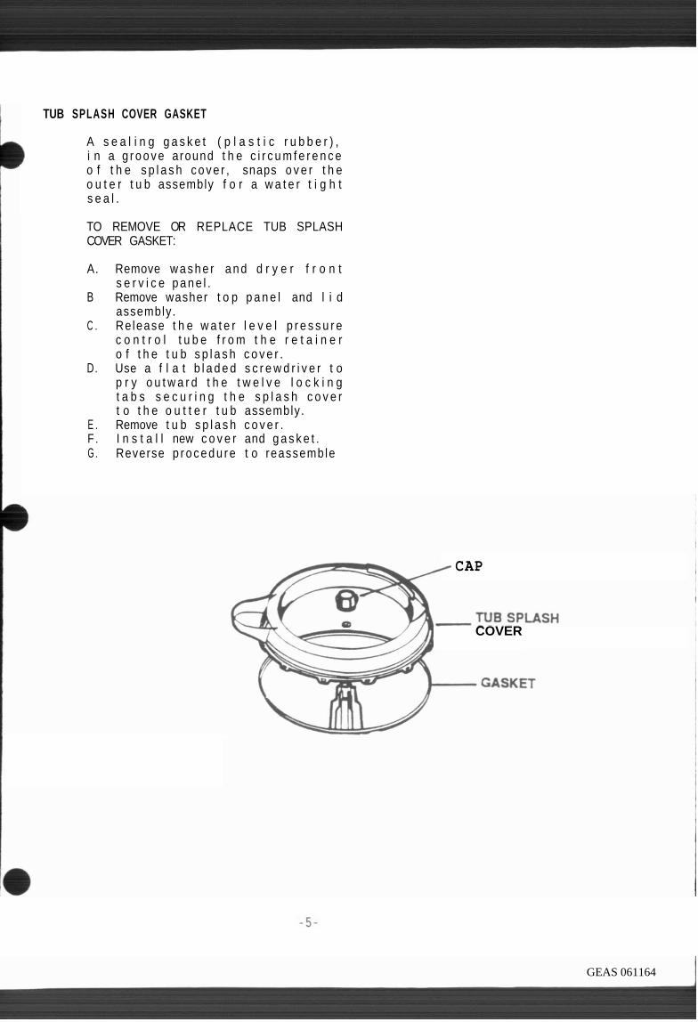
TUB SPLASH COVER GASKET
1 A s e a l i n g g a s k e t ( p l a s t i c r u b b e r ) , i n a g r o o v e around t h e c i r c u m f e r e n c e o f t h e s p l a s h c o v e r , snaps o v e r t h e o u t e r t u b assembly f o r a w a t e r t i g h t s e a l .
TO REMOVE OR REPLACE TUB SPLASH COVER GASKET:
A. Remove w a s h e r a n d d r y e r f r o n t s e r v i c e p a n e l .
B Remove washer t o p p a n e l and l i d assembly.
C . Re lease t h e w a t e r l e v e l p r e s s u r e c o n t r o l t u b e f r o m t h e r e t a i n e r o f t h e t u b s p l a s h c o v e r .
D. Use a f l a t b l a d e d s c r e w d r i v e r t o p r y o u t w a r d t h e t w e l v e l o c k i n g t a b s s e c u r i n g t h e s p l a s h c o v e r t o t h e o u t t e r t u b assembly.
E . Remove t u b s p l a s h c o v e r . F . I n s t a l l new c o v e r and g a s k e t . G . Reverse p r o c e d u r e t o reassemble
/ CAP
- w\:.-" ?/A COVER
GEAS 061164

INNER WASH BASKET
INNER
The i n n e r wash b a s k e t i s made o f p o l y p r o p y l e n e , p e r f o r a t e d a t t h e b o t t o m and s i d e s t o s e p a r a t e l i n t and s o i l d f r o m t h e c l o t h e s d u r i n g a g i t a t i o n , and t o e x t r a c t t h e water d u r i n g sp in . The i n n e r wash baske t has a b u i l t - i n u p p e r w e i g h t r i n g ( l i q u i d f i l l e d ) . The i n n e r wash basket i s suppor ted by t he t runn ion , and i s h e l d i n p l a c e by f i v e b o l t s . The t r u n n i o n i s fastened t o t h e sp in s h a f t w i t h a l o c k p l a t e . T h e l o c k p l a t e i s l o c a t e d i n a m i l l e d a r e a o n t h e s p i n s h a f t a n d i s f a s t e n e d t o t h e t r u n n i o n w i t h two hex head bo l t s .
TO R E M O V E OR REPLACE INNER WASH BASKET:
A. Remove d r y e r and washer f r o n t s e r v i c e panel .
B. Remove washer t o p panel and l i d C . Release t h e wate r l e v e l pressure
c o n t r o l t ube f rom sp lash cover . D. Remove t u b sp lash cover . E . Remove cap and a g i t a t o r . F. Remove 5 3/8" hex b o l t s secur ing
t h e i n n e r wash b a s k e t t o t h e t r u n n i o n .
G . S l i d e i n n e r wash baske t up and o f f t h e t r ansm iss ion s h a f t .
H. I n s t a l l new i n n e r basket. I. Reverse procedure t o reassemble.
WASH BASKET L INT FILTER
The i n n e r wash b a s k e t has a s e l f c l e a n i n g l i n t f i l t e r i nco rpo ra ted i n t h e base o f t h e i n n e r wash baske t . I t i s n o t n e c e s s a r y t o c l e a n t h e f i l t e r , t h e f i l t e r i s r i n s e d c l e a n d u r i n g t h e s p i n c y c l e .
TUBE
UPPER SPIN BEARING
Inner Wash Basker Mounting Details
GEAS 061165

TRUNNION
The t r u n n i o n s u p p o r t s t h e i n n e r wash 1 b a s k e t , and i s mounted t o t h e s p i n
s h a f t b y a l o c k i n g p l a t e .
TO REMOVE OR REPLACE TRUNNION:
Remove w a s h e r and d r y e r f r o n t s e r v i c e pane l . Remove washer t o p pane l and l i d assembly . Re lease t h e w a t e r l e v e l p r e s s u r e c o n t r o l t u b e f r o m t h e s p l a s h c o v e r . Remove t u b s p l a s h c o v e r . Remove cap and a g i t a t o r . Remove 5 3/8" hex b o l t s s e c u r i n g t h e i n n e r w a s h b a s k e t t o t r u n n i o n . S l i d e i n n e r wash b a s k e t up and o f f t h e t r a n s m i s s i o n s h a f t . L o o s e n t w o 1 / 2 " h e x b o l t s s e c u r i n g t r u n n i o n 1 o c k p l a t e t o m i l l e d f l a t o f t h e s p i n s h a f t . Remove t r u n n i o n . I n s t a l l new t r u n n i o n and a p p l y l o c t i t e . Reverse p r o c e d u r e t o reassemb le .
WATER SEAL ASSEMBLY
T h e w a t e r s e a l a s s e m b l y s i t s u n d e r n e a t h t h e t r u n n i o n and i n s i d e t h e u p p e r b e a r i n g h o u s i n g o f t h e t r a n s m i s s i o n . I t s e a l s t h e w a t e r i n s i d e t h e o u t e r t u b . The assembly c o n s i s t o f a r u b b e r and b r o n z e s e a l , a n d a c a r b o n m a t i n g s e a l s u r f a c e m o u n t e d o n a s p r i n g l o a d e d r u b b e r b e l l o w s . T h e b e 1 l o w s s e a l i s p r e s s e d i n t o t h e u p p e r b e a r i n g h o u s i n g m o u n t e d w i t h i n t h e o u t e r t u b . A s l i n g e r washer comp le tes t h e assernbl y .
INNER WASH BASKET !NHER WASH BASKET MOUNTING BOLTS
MOUNTING BOLTS TRUNNION LOCK PLATE
Inner Wash Basket and Trunn~on
UPPER SPIN TUBE UPPER SEAL
OUTER TUB BRONZE BEARING WATER SEAL ASSEMBLY
Water Seal Assemolv
GEAS 061166

r
TO REMOVE OR REPLACE WATER SEAL ASM.
A. Remove w a s h e r / d r y e r f r o n t s e r v i c e panel
B. Remove washer t o p panel and l i d . C . R e l e a s e w a t e r l e v e l p r e s s u r e
c o n t r o l t u b e f r o m t h e s p l a s h cover .
D. Remove t u b sp lash cover. E . Remove cap and a g i t a t o r . F. Remove t r u n n i o n a n d i n n e r
baske t . G. Remove b ronze washer f r o m s p i n
s h a f t . Do n o t l u b r i c a t e s e a l , rep1 ace.
OUTER TUB ASSEMBLY
The o u t e r t u b and a i r dome i s made o f p o l y p r o p y l e n e and i s mounted t o t h e l e g - a n d - d o m e a s s e m b l y . The d r a i n hose ( t u b t o pump) and upper s p i n bea r i ng a re i n s t a l l e d o n t o t h e o u t e r t u b . The a i r dome on t h e t u b s i d e p rov ides t h e connec t ion f o r t h e p ressure s w i t c h hose.
TO REMOVE OR REPLACE OUTER TUB ASM.
A . R e m o v e w a s h e r / d r y e r f r o n t s e r v i c e panel
B. Remove t h e washer t o p p a n e l / l i d . C . Release w a t e r p r e s s u r e c o n t r o l
tube f rom t h e sp lash cover. D. Remove t u b sp lash cover . E. Remove cap and a g i t a t o r . F . Remove t h e 5 3/8" hex b o l t s
s e c u r i n g t h e i n n e r wash baske t t o t r u n n i o n .
G. L o o s e n t w o 1 / 2 " h e x b o l t s secu r i ng t r u n n i o n 1 ock p l a t e t o m i l l e d f l a t o f t h e sp in s h a f t .
H. Remove t r u n n i o n . I. Remove washer d r i v e be1 t . J. Remove o u t e r t u b t o pump c lamp
and hose. K . L o o s e n a l l e n s e t s c r e w a n d
r e m o v e t r a n s m i s s i o n d r i v e p u l l e y .
-8-
1
GEAS 061167

R e m o v e t w o 3 / 8 " h e x b o l t s s e c u r i n g t r a n s m i s s i o n t o l e g and dome assembly. Remove t h r e e d 1 / 2 " h e x b o l t s s e c u r i n g t h e o u t e r wash t u b t o t h e l e g and dome asm. L i f t w a s h e r t r a n s m i s s i o n a n d o u t e r t u b assembly f r o m l e g and dome assembly . Remove b r o n z e washe r f r o m s p i n s h a f t . Remove w a t e r s e a l , s l i n g e r f r o m b e a r i n g h o u s i n g and s l i d e up and o f f s p i n s h a f t . L i f t o u t e r wash t u b up and o f f t r a n s m i s s i o n s h a f t . Remove t w o screws s e c u r i n g upper s p i n b e a r i n g t o t h e b o t t o m o f t h e o u t e r wash t u b . Remove o u t e r t u b - t o - p u m p h o s e ( s e a l w i t h a d h e s i v e u p o n r e a s s e m b l y ) . I n s t a l 1 t o c o m p l e t e assembly.
STABILIZING SPRINGS . E a c h v e r t i c a l s t a b i l i z i n g s p r i n g hooks i n t o an a d j u s t a b l e t a b fo rmed i n t h e w a s h e r b a s e p a n and t o t h e u p p e r e n d o f t h e l e g a n d dome assemb ly . These t h r e e s p r i n g s keep t h e w a s h e r t u b c e n t e r e d d u r i n g o p e r a t i o n a n d h o l d t h e w a s h e r mechanism a g a i n s t t h e snubbe r r i n g . T h e r e d s t a i n e d s p r i n g m u s t b e i n s t a l l e d o p p o s i t e t h e washer d r i v e mo to r and pump assembly . Each h o r i z o n t a l s t a b i l i z e r s p r i n g h o o k s i n t o t h e l e g - a n d - d o m e and a r a i s e d t a b o n t h e washe r base pan. These t h r e e s p r i n g s a i d i n k e e p i n g t h e mechanism s t a b l e and c e n t e r e d on I t h e crown o f t h e washer base pan.
-1ORfZONl A L SPRING 4ERTlCAL SPRING AajL--.J:NT
Stabilizer S p r i n ~ j
GEAS 061168

TO ADJUST VERTICAL S T A B I L I Z E R SPRINGS.
When t h e w a s h e r i s i n t h e s p i n c y c l e , t h e t u b s p l a s h c o v e r ( s u b t o p ) s h o u l d b e c e n t e r e d i n t h e c a b i n e t . I f o f f cen te r , a d j u s t each v e r t i c a l s p r i n g a s r e q u i r e d . E x c e s s i v e o u t o f ba l ance l o a d s may cause t h e washer s p l a s h cove r ( sub t o p ) t o s t r i k e t h e c a b i n e t . Pressure o f t he leg-and-dome aga ins t t h e s n u b b e r c a n be i n c r e a s e d o r decreased by e q u a l l y a d j u s t i n g t h e t e n s i o n o f t h e v e r t i c a l s p r i n g s .
i Use a p a i r o f v i c e g r i p p l i e r s t o a d j u s t s p r i n g s .
/ WATER PUMP ASSEMBLY
The w a t e r pump ( a one p i e c e sea l a s m . ) i s m o u n t e d a v o v e a w a t e r s h i e l d on t o p o f t h e washer d r i v e motor by two s p r i n g c l i p s NOTE: Should t h e washer o u t e r wash t u b be f u l l o r p a r t i a l l y f u l l o f water , and t h e washer d r i v e motor i s i n o p e r a t i v e , remove t h e i n l e t d r a i n hose clamp. I n s e r t a sma l l b l aded s c r e w d r i v e r a l o n g s i d e t h e d r a i n i n l e t hose a l l o w i n g s m a l l f l o w o f w a t e r i n t o w a t e r s h i e l d . P l a c e a p a n u n d e r t h e o v e r f l o w t o c a t c h wa te r
INTERIOR DRAIN HOSE
\
GEAS 061169
TO REMOVE OR REPLACE PUMP A. Remove t h e washer f r o n t s e r v i c e
p a n e l . B. Remove t h e d r a i n hose, i n l e t and
o u t l e t h o s e s , a n d c l a m p s f r o m t h e w a t e r pump assembly. No te : t o g a i n w o r k i n g space t o remove t h e w a t e r pump, remove t h e f r o n t o u t e r wash t u b t o l e g - a n d - d o m e f r o n t m o u n t i n g b o l t , l i f t up on o u t e r wash t u b a s s e m b l y , a n d r e i n s t a l 1 b o l t i n t o leg-and-dome assembly b o l t home.
C . Remove two s p r i n g m o u n t i n g c l i p s s e c u r i n g w a t e r pump a s s e m b l y t o washer d r i v e m o t o r . N o t e : Upon r e a s s e m b l y , be s u r e e l e c t r i c a l l e a d s d o n o t b e c o m e p i n c h e d u n d e r s p r i n g c l i p s .
D. L i f t pump u p a n d o f f w a s h e r d r i v e m o t o r s h a f t .
E. I n s t a l l new w a t e r pump assembly. F . Reverse p r o c e d u r e t o reassemble .
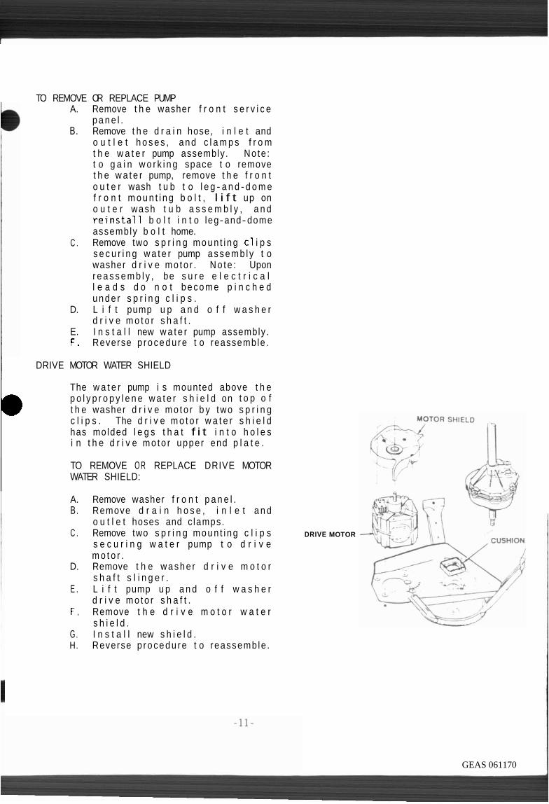
I DRIVE MOTOR WATER SHIELD
0 The w a t e r pump i s mounted above t h e p o l y p r o p y l e n e w a t e r s h i e l d on t o p o f t h e washer d r i v e m o t o r b y two s p r i n g c l i p s . The d r i v e m o t o r w a t e r s h i e l d has molded l e g s t h a t f i t i n t o h o l e s i n t h e d r i v e m o t o r uppe r end p l a t e .
TO REMOVE O R REPLACE DRIVE MOTOR WATER SHIELD:
A. Remove washer f r o n t p a n e l . B. Remove d r a i n h o s e , i n l e t a n d
o u t l e t hoses and c lamps. C . Remove two s p r i n g m o u n t i n g c l i p s
s e c u r i n g w a t e r pump t o d r i v e m o t o r .
D. Remove t h e w a s h e r d r i v e m o t o r s h a f t s l i n g e r .
E . L i f t pump u p a n d o f f w a s h e r d r i v e m o t o r s h a f t .
F . Remove t h e d r i v e m o t o r w a t e r s h i e l d .
G. I n s t a l l new s h i e l d . H. Reverse p r o c e d u r e t o reassemb le .
DRIVE MOTOR
GEAS 061170

WASHER D R I V E MOTOR
The w a s h e r d r i v e m o t o r i s a two speed, 1 /2 h .p . , c a p a c i t o r s t a r t , r e v e r s i b l e moto r r a t e d a t 120 v o l t s , 60 h e r t z . The c o n n e c t i o n s t o t h e m o t o r a r e q u i c k d i s c o n n e c t t y p e t e r m i n a l b laocks . The washer d r i v e moto r i s mounted t o t h e leg-and-dome assembly and d r i v e s t h e t ransmiss ion by a p u l l e y mounted on i t s s h a f t , a
I d r i v e b e l t , a n d b e l t i d l e r a r m MOTOR S W ~ C H DRIVE MOTOR assembly. \
TO R E M O V E O R REPLACE WASHER DRIVE MOTOR : A. Remove washer f r o n t panel . B. Remove t h e d r a i n hose, i n l e t and
o u t l e t hoses , and clamps f r o m t h e wa te r pump assembly.
C . Remove two s p r i n g mount ing c l i p s secu r i ng wa te r pump assembly t o washer d r i v e motor .
D. L i f t pump up and o f f w a s h e r d r i v e moto r s h a f t .
E . Remove d r i v e m o t o r b e l t ( r o l l o f f ) .
F. isc connect washer d r i v e mo to r , e l e c t r i c a l t e r m i n a l c o n n e c t o r b l ocks .
G Remove f o u r hex n u t s s e c u r i n g t h e washer d r i v e motor .
H. Remove t h e washer d r i v e motor I. I n s t a l l new d r i v e motor.
WASHER D R I V E MOTOR BELT
The washer d r i v e moto r b e l t i s used t o t r a n s m i t power f r o m t h e washer d r i v e m o t o r t o t h e wash and s p i n b a s k e t . An i d l e r a r m p u l l e y m a i n t a i n s p r o p e r d r i v e b e l t t ens i on .
TO R E M O V E OR REPLACE WASHER DRIVE MOTOR BELT:
A . Remove t h e washer s e r v i c e panel . B. Remove t h e d r i v e m o t o r b e l t
( r o l l o f f ) . C . I n s t a l l new washer d r i v e motor. D. Reverse p rocedure t o reassemble.
Y WIRING CONNECTOR BLOCKS
Washer Drive Motor
GEAS 061171

WASHER D R I V E MOTOR B E L T IDLER ARM
The washer d r i v e motor b e l t i s used t o t r a n s m i t power f r o m t h e washer d r i v e m o t o r t o t h e wash and s p i n b a s k e t . T h e i d l e r a r m p u l l e y ma in ta i ns p rope r d r i v e b e l t t ens i on . The d r i v e system p r o v i d e s p o s i t i v e d r i v e i n a g i t a t i o n ( c l o c k w i s e r o t a t i o n ) , and v a r i a b l e speed d r i v e i n s p i n (coun te rc lockw ise r o t a t i o n ) . T h i s dual d r i v e f u n c t i o n i s a r e s u l t o f t h e d i r e c t i o n o f t h e d r i v e . I n a g i t a t i o n , t h e d i r e c t i o n o f p u l l i s f r o m p u l l e y t o p u l l e y . T h i s causes t h e b e l t t o r i d e t i g h t i n t he p u l l e y and p r o v i d e p o s i t i v e d r i v e . I n s p i n , t h e d i r e c t i o n o f p u l l i s a c r o s s t h e s p r i n g 1 o a d e d i d l e r p u l l e y . The i d l e r arm "senses" t h e l o a d and c o n t r o l s b e l t t e n s i o n t o p r o v i d e a g radua l i nc rease i n speed as w a t e r i s e x t r a c t e d . W i t h an extreme o u t o f balance load , t h e t u b w i l l s p i n a t r educed speed d u r i n g t h e s p i n c y c l e . T h i s p e r m i t s t h e washer t o complete t he f u l l c y c l e .
TO REMOVE OR REPLACE WASHER D R I V E MOTOR BELT IDLER ARM:
A. Remove washer f r o n t panel . B. Remove d r i v e motor be1 t ( r o l l
o f f ) . C . R e m o v e " C " c l i p r e t a i n e r
s e c u r i n g i d l e r arm assembly t o 1 et-and-dome.
D. I n s t a l l new washer d r i v e m o t o r be1 t i d l e r arm.
E . P l ace i d l e r arm t e n s i o n s p r i n g i n t o 3 r d h o l e f rom motor .
F . Reverse orocedure t o reassemble.
WASHER DRIVE MOTOR DRIVE BELT
IDLER ARM TENSION SPRING LEG-AND-DOME
ldler Arm Ad~ustrnent
IDLER ARM TENSION ADJUSTMENT SPRING
RETAINING RING WASHER PIVOT SLEEVE
ldler Arm Details
GEAS 061172

ADJUST DRIVE BELT IDLER ARM TENSION
A. Check pump ou t wattage. Wattage mus t be w i t h i n s p e c i f i c a t i o n s recommended w i t h f u l l water 1 oad
B. T i g h t e n s p r i n g t o i n c r e a s e w a t t a g e . L o o s e n s p r i n g t o decrease wattage.
C . F i l l i n n e r wash b a s k e t w i t h w a t e r t o h i g h l e v e l (maximum) and advance t i m e r t o sp in cyc le . Warn ing : Do n o t r e s t r i c t l i d l o c k a r m w h e n m a n u a l l y d e p r e s s i n g o r damage t o 1 i d s w i t c h b i - m e t a l e l e m e n t w i l l occur and a f f e c t l o c k and un lock t ime.
D. S t a r t s p i n c y c l e : I f w a t e r b e g i n s pumping o u t b e f o r e t h e s p i n basket s t a r t s t o s p i n , t h e b e l t t e n s i o n i s t o o l o o s e . T i gh ten t h e s p r i n g two ho les f o r a n e w b e l t a n d o n e f o r a n e x i s t i n g b e l t . R e c h e c k b y s t a r t i n g s p i n c y c l e again.
PROPER ADJUSTMENT OF THE IDLER ARM TENSION I S NECESSARY FOR TROUBLE FREE OPERATION OF THIS DRIVE SYSTEM.
WATER INLET HOSE AND NOZZLE
T h e w a t e r i n l e t h o s e a n d p o l y p r o p y l e n e n o z z l e p r o v i d e an a n i t - s y p h o n d e v i c e f o r t h e incoming wate r supply . Water f l ows f rom t h e w a t e r i n l e t va l ve through t h e i n l e t hose, i n l e t n o z z l e , and t h e n i n t o t h e i n n e r wash b a s k e t . The wa te r i n l e t n o z z l e i s a t t a c h e d t o t h e d r y e r bot tom pan.
A . R e m o v e w a s h e r / d r y e r f r o n t s e r v i c e panel .
B. Remove t h e washer t o p panel and 1 i d .
C . L o o s e n s c r e w s e c u r i n g w a t e r i n l e t va l ve s h i e l d .
D Remove wa te r i n l e t va l ve s h i e l d by p u l l i n g up.
E . Remove w a t e r i n l e t f i l l v a l v e c l amp and hose.
F. Remove s c r e w s e c u r i n g w a t e r i n l e t nozz le t o t h e d r y e r base.
GEAS 061173
BLEACH DISPENSER CUP
The w h i t e p o l y p r o p y l e n e b l each cup snaps i n t o t h e washe t o p panel and i s f o r L IQUID BLEACH ONLY.
TO REMOVE OR REPLACE DISPENSER CUP:
A . Remove b l e a c h d i s p e n s e r cup by p r y i n g up o r pushing up from t h e bottom.
B. I n s t a l l new cup by snapping i n t o p l ace .
L ID AND HINGES
The washe r l i d i s c o n s t r u c t e d o f h e a v y gauge s t e e l f i n i s h e d i n a powdered p a i n t c o a t . The h i n g e , h i n g e cam, d o o r l o c k s t r i k e , and r u b b e r bumpers a r e mounted t o t h e 1 i d .
TO REMOVE OR REPLACE LID/HINGES:
Remove d r y e r f r o n t access panel . Washer f r o n t s e r v i c e panel . D i s c o n n e c t w a s h e r l i d l o c k s w i t c h t e r m i n a l connector . Remove t h e washer t op panel and l i d assembly. R e l e a s e t h e w a s h e r 1 i d coun te rba lance h inge sp r i ng . Remove t w o sc rews and g a s k e t secu r i ng (LH) h inge t o 1 i d . Remove l i d h inge from washer t o p panel and grommet. Remove l i d (RH) h i nge cam, l i d a s s e m b l y , l i d h i n g e grommets, two screws secu r i ng 1 i d s t r i k e , and rubbe r bumpers. Reverse procedure t o reassemble. (Note: L u b r i c a t e (RH) h inge cam s p r i n g .
GEAS 061174

WASHER BASE
The base pan assembly which serves a s t h e s u p p o r t f o r t h e e n t i r e washer/dryer i s cons t ruc ted o f heavy gauge me ta l embossed f o r s t r e n g t h . The base assembly i s suppo r ted by l e v e l i n g l e g s , one on each f r o n t c o r n e r w i t h r u b b e r i n s e r t s . The r e a r i s suppor ted by se l f - l e v e l i n g l e g assembly welded t o t h e base pan. The r a i s e d p o r t i o n a t t he c e n t e r o f INNER WASH
t h e base p rov ides a suppor t su r face BASKET
f o r t h e snubber r i n g and s t a b i l i z e s t h e t u b and t r a n s m i s s i o n d u r i n g sp in .
WASHER UNIT AND BASE REMOVAL: . , A. Remove f r o n t s e r v i c e panels . B. Remove washer t o p panel and l i d . C . Remove wate r l e v e l pressure f i l l . ,
s w i t c h t ube a t t h e wa te r l e v e l p ressure c o n t r o l sw i tch .
D. R e l e a s e m o t o r e l e c t r i c a l p l u g connec to rs . O r n R W1
TUB E. Remove d r a i n hose and clamp from
connector . F . Remove 9 screws secur ing washer
c a b i n e t t o b a s e . ( s u p p o r t c a b i n e t s i d e s w i t h a 2 " x 2 " MOUNTING
board) . G . S l i d e washer u n i t and base away
f rom c a b i n e t ; be c a r e f u l n o t t o damage f l o o r .
WASHER BASE ASSEMBLY
WASHER BASE PAN
TO REMOVE OR REPLACE WASHER BASE Inner Wash Basket Mounr~ng Deta~ls PAN :
A. Remove washer u n i t and base pan assembly.
B . Release t h r e e v e r t i c a l and t h r e e h o r i z o n t a l c o u n t e r b a l a n c e sp r i ngs . NOTE: The h o r i z o n t a l s p r i n g w i t h t h e r e d p a i n t mark ing i s mounted o p p o s i t e t h e d r i v e motor.
C . Remove w a s h e r t r a n s m i s s i o n , i n n e r wash basket, and o u t e r t u b assembly f rom base pan.
D. Remove snubber r i n g . E. I n s t a l l new base pan assembly.
GEAS 061175

WATER INLET NOZZLE
T h e w a t e r i n l e t h o s e a n d p o l y p r o p y l e n e n o z z l e p r o v i d e a n i t - s y p h o n dev i ce f o r t h e incoming water supply . Water f l ows f rom t h e wa te r i n l e t v a l v e th rough t he i n l e t hose, i n l e t n o z z l e , and t h e n i n t o t h e i n n e r wash b a s k e t . The wate r i n l e t n o z z l e i s a t t a c h e d t o t h e d r y e r bot tom pan.
DRAIN HOSE CHECK VALVE
A check v a l v e i s i n s t a l l e d i n t h e d r a i n sys tem t o r e d u c e s u d s i n g by p r e v e n t i n g a i r i n t a k e b y t h e pump d u r i n g a g i t a t i o n . The check v a l v e i s i n s t a l l e d i n t h e p l a s t i c d r a i n hose c o u p l i n g l o c a t e d a t t h e r e a r o f t he washer. I t i s p o s i t i o n e d i n s i d e t he coupl i ng. The semi - c i r c u l a r 1 i p o f t h e v a l v e shou ld be p o s i t i o n e d up i n t o t h e d r a i n hose.
TO REMOVE O R REPLACE DRAIN HOSE CHECK VALVE.
I A . Loosen t h e clamp and remove t he e x t e r i o r d r a i n hose f r o m t h e cab ine t coupl i n g .
B. Remove t h e d r a i n h o s e c h e c k v a l v e by p u l l i n g o u t .
C . I n s t a l l new d r a i n hose c h e c k v a l v e ; be s u r e o f t h e c o r r e c t p o s i t i o n o f t h e check va lve .
D. Reverse procedure t o reassemble.
GEAS 061176
INTERIOR DRAIN HOSE
The i n t e r i o r d r a i n hose a t taches t o t h e w a t e r pump and connec ts t o t h e c a b i n e t e x t e r i o r .
DRAIN HOSE CONNECTOR
The i n t e r i o r d r a i n hose a t taches t o t h e w a t e r pump a n d c o n n e c t s t h e c a b i n e t t o t h e e x t e r i o r connector .
TO REMOVE OR REPLACE:
A . Remove w a s h e r f r o n t s e r v i c e pane l .
8. Loosen t h e clamp and remove t h e i n t e r i o r d r a i n hose f r o m t h e c a b i n e t coup l i ng .
C . Remove t h e e x t e r i o r d r a i n hose and clamp.
D. Remove one sc rew s e c u r i n g t h e d r a i n h o s e c o n n e c t o r t o t h e c a b i n e t .
E. I n s t a l l new e x t e r i o r d r a i n hose connec to r .
F . Reverse procedure t o reassemble.
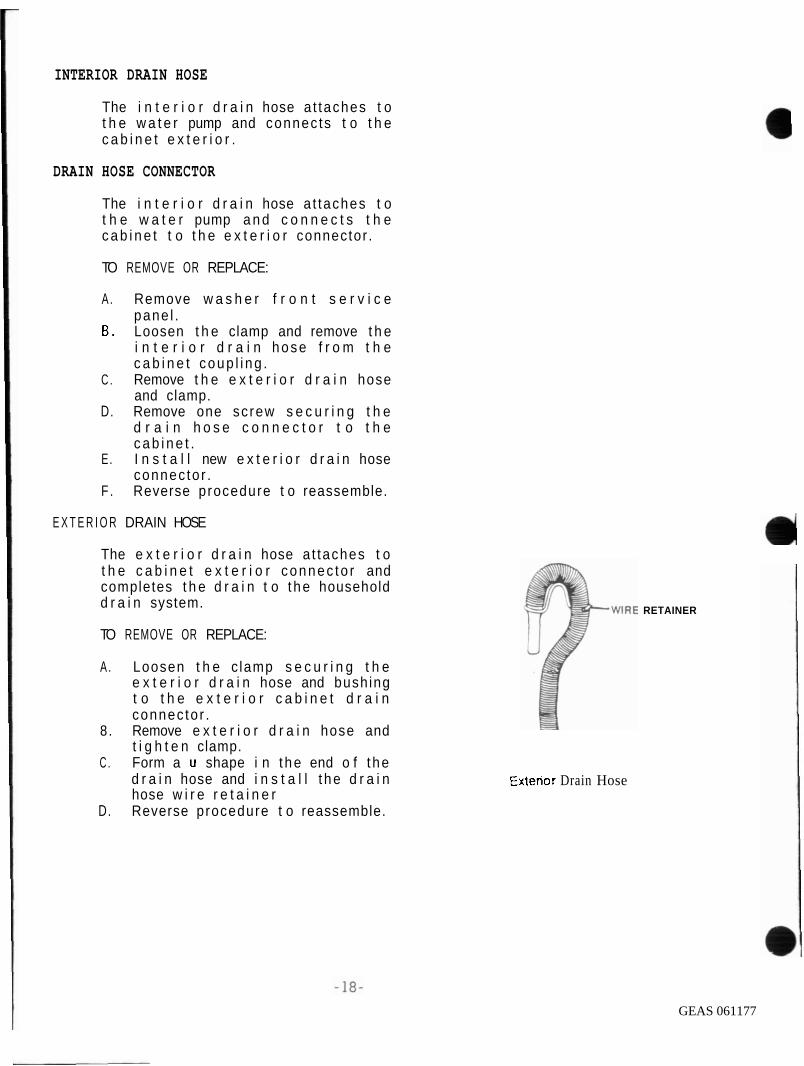
E X T E R I O R DRAIN HOSE
The e x t e r i o r d r a i n hose a t taches t o t h e c a b i n e t e x t e r i o r connec to r and completes t h e d r a i n t o t he household d r a i n system.
TO REMOVE OR REPLACE:
A . Loosen t h e c lamp s e c u r i n g t h e e x t e r i o r d r a i n hose and bushing t o t h e e x t e r i o r c a b i n e t d r a i n connec to r .
8 . Remove e x t e r i o r d r a i n hose and t i g h t e n clamp.
C . Form a u shape i n t he end o f t he d r a i n hose and i n s t a l l t he d r a i n hose w i r e r e t a i n e r
D. Reverse procedure t o reassemble.
Extenor Drain Hose
RETAINER
GEAS 061177

WASHER ELECTRICAL COMPONENTS TEST AND REPAIR
CAUTION! ALWAYS DISCONNECT U N I T FROM ELECTRICAL POWER SOURCE BEFORE MAKING ANY ELECTRICAL TEST.
WASHER DRIVE MOTOR
TWO
The washe r d r i v e m o t o r i s e i t h e r a s i n g l e o r a t w o s p e e d , 1 /2 h . p . , c a p a c i t o r s t a r t , r e v e r s i b l e m o t o r , r a t e d a t 1 2 0 v o l t s , 6 0 h z . The c o n n e c t i o n s a t t h e m o t o r s w i t c h a r e q u i c k d i s c o n n e c t t y p e t e r m i n a l b l o c k s . T h e t e r m i n a l b l o c k s a r e m o l d e d i n s u c h a way t h a t t h e y c a n n o t b e r e v e r s e d . An i n t e r n a l o v e r l o a d p r o t e c t o r i s b u i l t i n t o t h e m o t o r a n d w i l 1 o p e n d u e t o e x c e s s i v e l y h i g h t e m p e r a t u r e s and/or e x c e s s i v e c u r r e n t . T h e o v e r l o a d p r o t e c t o r i s w i r e d i n s e r i e s w i t h t h e w a s h e r c i r c u i t r y a n d i f i t o p e n s , a l l w a s h e r o p e r a t i o n s w i l l s t o p . T h e p r o t e c t o r i s s e l f r e s e t t i n g and i n some cases t a k e s as l o n g as t h i r t y seconds t o r e s e t .
SPEED DRIVE MOTOR
The h i g h speed s t a r t s on t h e 4 - p o l e ma in w i n d i n g i n c o n j u n c t i o n w i t h t h e 4 - p o l e phase ( s t a r t ) w i n d i n g . A f t e r t h e m o t o r h a s a c c e l e r a t e d s u f f i c i e n t l y t o a c t u a t e t h e s t a r t s w i t c h , t h e s t a r t w i n d i n g i s d e - e n e r g i z e d . When t h e l o w speed i s s e l e c t e d , t h e m o t o r s t a r t s o n t h e 4 - p o l e ma in w i n d i n g and s w i t c h e s t o t h e l o w speed 6 - p o l e w i n d i n g a f t e r t h e m o t o r h a s a c c e l e r a t e d t o open t h e s t a r t s w i t c h .
I f an open c i r c u i t e x i s t s i n t h e l o w speed 6 - p o l e w i n d i n g , t h e m o t o r w i l l r e p e a t e d l y s t a r t and s t o p on t h e l o w speed s e l e c t i o n .
I WHITE
MOTOR 1
CAPACITOR
One Speed Motor
WHITE YOTDQ I I *eM: HIGH 1 F+
4 CAPACITOR
TWO Speed Motor
Washer Dr~ve Motor
GEAS 061178

WASHER HOTOR TESTING
CAUTION! DISCONNECT UNIT FROM ELECTRICAL POWER SOURCE BEFORE HAKING ANY CONTINUITY TEST.
I f t h e m o t o r r u n s i n one d i r e c t i o n , b u t w i l l n o t r e v e r s e , t h e t i m e r o r w i r i n g h a r n e s s i s a t f a u l t because t h e same m o t o r components a r e u s e d w h e n t h e m o t o r r u n s i n e i t h e r d i r e c t i o n .
Use a 120 v o l t t e s t c o r d w i t h f o u r m a l e t e r m i n a l s , t w o w i r e s o n t h e 1 i v e s i d e , t w o w i r e s on t h e n e u t r a l s i d e , a n d a f i f t h w i r e f o r t h e g r o u n d t o t e s t t h e m o t o r .
CIRCUIT BREAKER OR FUSE
-4 HOT LEADS
115 VOLT PLUG - NEUTRAL (WITH GROUND) 4- LEADS
JUMPER - WlRE
Test Cord
C o n n e c t i o n s a r e made t h r o u g h t h e m o t o r s w i t c h l o c a t e d a t t h e t o p o f t h e m o t o r .
TO* Cord Motor Leads Shaft Rotmtlon 6 sp&
brim 2 6 5 Countercloorwtse - Fast Neutral 1 6 4 L~ne 7 6 5 Counlerc~oaw~se - S ow Neutral 1 6 4 L ~ n e 2 6 4 Clockw~so - Fast - -
Neutral 1 6 5 Line 7 8 4 Clodtw~se - Slow - -
Neutral 1 6 5
I l l u s t r a t i o n a b o v e shows i n t e r n a l w i r i n g d i a g r a m o f t h e o n e and t w o speed c a p a c i t o r s t a r t t y p e m o t o r s . I f t h e m o t o r f a i l s t o o p e r a t e d u r i n g a n y o f t h e t e s t o u t l i n e d a b o v e , r e p l a c e t h e m o t o r .
GEAS 061179

WASHER DRIVE MOTOR START SWITCH
I The washe r d r i v e m o t o r s t a r t s w i t c h i s mounted e x t e r n a l l y t o t h e t o p o f t h e w a s h e r d r i v e m o t o r and i s n o t r e p 1 aceab l e.
CAPACITOR
A 189- 210 m i c r o f a r a d , 120 v o l t , 6 0 h z . r a t e d s t a r t i n g c a p a c i t o r i s used w i t h e i t h e r t h e o n e o r t w o s p e e d w a s h e r d r i v e m o t o r , b e c a u s e t h e m o t o r r e q u i r e s t o r q u e a s s i s t a n c e t o t h e t h e r o t o r s t a r t e d .
The s t a r t c a p a c i t o r i s mounted t o a b r a c k e t w h i c h i s m o u n t e d t o t h e washer i n t e r i o r c a b i n e t .
N o t e : I f t h e m o t o r w i l l n o t r u n o r t r i e s t o s t a r t and s h u t s o f f , t h e p r o b l e m m a y b e a n i n o p e r a t i v e c a p a c i t o r .
The c a p a c i t o r can be t e s t e d b y u s i n g a n o h m m e t e r s e t o n h i g h s c a l e . (Most d i g i t a l ohmmeters d o n o t have
b s u f f i c i e n t b a t t e r y s t r e n g h t t o t e s t a c a p a c i t o r ; t h e t e s t m a y b e m i s l e a d i n g . ) W i t h t h e p o w e r d i s c o n n e c t e d , d i s c o n n e c t one o f t h e t e r m i n a l w i r e s a n d c o n n e c t t h e ohmmeter a c r o s s t h e t e r m i n a l s .
CAUTION! BEFORE CHECKING ANY CAPACITOR, MAKE CERTAIN THAT IS IS DISCHARGED. TO D I S C H A R G E , R E M O V E L E A D S A N D S H O R T CAPACITOR TERMINAL WITH A JUMPER WIRE. REMOVE JUMPER WIRE.
GEAS 061180

CAPACITOR TESTING
A. D i s c h a r g e c a p a c i t o r . B. Measu re t h e r e s i s t a n c e b e t w e e n
t h e t w o c a p a c i t o r t e r m i n a l s . I f t h e c a p a c i t o r i s goo, t h e m e t e r s h o u l d i n d i c a t e c o n t i n u i t y f o r a s h o r t p e r i o d o f t i m e ( w h i l e t h e c a p a c i t o r i s c h a r g i n g ) , t h e n s h o u l d i n d i c a t e an open c i r c u i t o n c e t h e c a p a c i t o r i s f u l l y cha rged . I f t h e o h m m e t e r i n d i c a t e s a c o n s t a n t c o n t i n u i t y be tween t h e t e r m i n a l s , t h e c a p a c i t o r i s s h o r t e d . I f t h e ohmmeter has n o i n i t i a l r e a d i n g , t h e n t h e c a p a c i t o r s h o u l d be rep1 aced.
TO REMOVE OR REPLACE WASHER DRIVE MOTOR START CAPACITOR.
A. R e m o v e w a s h e r f r o n t s e r v i c e access p a n e l .
B. R e m o v e c a p a c i t o r f r o m i t s m o u n t i n g b r a c k e t , t h e c a p a c i t o r m o u n t i n g b r a c k e t c l i p s t o washer c a b i n e t r e a r .
C . Remove w i r i n g . D. I n s t a l l c a p a c i t o r . E . Reverse p r o c e d u r e t o reassemble .
WASHER TIMER
T h e w a s h e r t i m e r c o n t r o l s t h e sequence o f o p e r a t i o n o f each o f t h e e l e c t r i c a l components o f t h e washer u s e d d u r i n g a c o m p l e t e w a s h i n g c y c l e . I t i s m a d e u p o f t h r e e a s s e m b l i e s : t h e t i m e r m o t o r , a s e r i e s o f cams, and s w i t c h e s .
T h e m o t o r i s a s y n c h r o n o u s t y p e m o t o r , s i m i l a r t o t h o s e u s e d i n e l e c t r i c c l o c k s , g e a r e d down t o o p e r a t e a pawl and r a c h e t mechanism w h i c h r o t a t e s t h e cams e v e r y 9 0 seconds. The a c t u a l movement o f t h e cam i s q u i t e r a p i d , t o i n s u r e q u i c k , p o s i t i v e o p e n i n g and c l o s i n g o f t h e s w i t c h c o n t a c t s and r e d u c e a r c i n g . C e r t a i n s w i t c h c o n t a c t s o p e r a t e a t s u b i n t e r v a l t i m e .
GEAS 061181

1 WASHER T I M E R T E S T I N G i
The use r must push i n the t ime knob and t u r n i t c lockw ise t o advance t h e t i m e r . P u l l i n g t h e t i m e r o u t w i l l s t a r t t h e washer , push knob i n t o s t op washer.
I C A U T I O N ! ADVANCING T H E T I M E R I N THE KNOB OUT P O S I T I O N ( W I T H 115 VOLTS ACROSS I T OR RUNNING) CAN DESTROY THE S W I T C H CONTACTS A N D P O S S I B L Y D A M A G E O T H E R W A S H E R COMPONENTS.
D ISCONNECT LAUNDRY CENTER FROM E L E C T R I C A L POWER SUPPLY BEFORE MAKING ANY C O N T I N U I T Y TEST.
To check t h e t i m e r motor ope ra t i on , d i s c o n n e c t t h e two l e a d s f r o m t h e t i m e r m o t o r and connec t them t o a p r o p e r 1 y f u s e d 1 2 0 v o l t s e r v i c e co rd .
P l u g t h e c o r d i n t o t h e w a l l r e c e p t a c l e and check i f t h e m o t o r g e a r i s t u r n i n g . M u l t i p l e s w i t c h c o n t a c t s a c t i v a t e d by a s e r i e s o f cams c o n t r o l t h e w a t e r d e l i v e r y , w a t e r t e m p e r a t u r e , mo to r , and l i d l o c k . De te rmine i f p o s s i b l e wh ich p e r i o d o f t h e c y c l e i s i n o p e r a t i v e .
When i t has been d e t e r m i n e d wha t p o r t i o n o f t h e c y c l e i s n o t f u n c t i o n i n g , check t h e c i r c u i t f r o m t h e t i m e r t o t h e component w i t h a c o n t i n u i t y t e s t e r . Wi th t h e knob o f t h e t i m e r o u t ( r u n n i n g p o s i t i o n ) , t u r n t h e t i m e r knob s l o w l y t h r o u g h t h e p o r t i o n o f t h e c y c l e you need t o t e s t . I f c o n t i n u i t y show p o s i t i v e , t h e c i r c u i t w i l l be c losed . I t may be n e c e s s a r y t o o p e r a t e t h e t i m e r w i t h a t e s t co rd a l l o w i n g t h e motor t o r o t a t e t h e cam no rma l l y .
The t i m e r shou ld be r e p l a c e d as an assembly and SHOULD NOT B E REPAIRED.
GEAS 061182

CONSOLE AND CONTROLS
The c o n s o l e and c o n t r o l s assembly c o n s i s t s o f t h e c o n s o l e c o n t r o l p a n e l , d r y e r t i m e r , d r y e r temperature s e l e c t o r switch, push t o s t a r t s w i t c h , washer t i m e r , water temperature s e l e c t o r swi tch , water level control switch, control knobs, ind ica to r l i g h t , e t c .
TO R E M O V E O R R E P L A C E C O N S O L E A N D CONTROLS ASSEMBLY.
A . Disconnect laundry c e n t e r from e l e c t r i c a l supply.
B . Remove w a s h e r / d r y e r f r o n t se rv ice access panel.
C . Remove four screws securing the console and con t ro l s assembly t o s ide panels .
D . D i sconnec t e l e c t r i c a l w i r i n g connector blocks.
E . Lay c o n s o l e a n d c o n t r o l s assembly on a protected surface and t r a n s f e r a l l r e m a i n i n g components and p a r t s .
F . I n s t a l l new c o n s o l e a n d / o r control s .
TO REMOVE OR R E P L A C E WASHER TIMER:
A . Remove d r y e r f r o n t s e r v i c e a c c e s s panel and s a f e t y cover panel.
B . Remove 4 sc rews s e c u r i n g t h e console and con t ro l s assembly t o s ide panels .
C . D i sconnec t e l e c t r i c a l w i r i n g connector blocks .
D . Lay c o n s o l e a n d c o n t r o l s assembly on a protected surface.
E . Remove t i m e r knob by push ing i n n e r k n o b i n a n d t u r n i n g c o u n t e r c l o c k w i s e u n t i 1 knob t h r e a d s o f f s h a f t ; pu l l o u t e r d i a l o f f t h e t imer s h a f t .
F. Remove two s c r e w s s e c u r i n g washer t imer t o control bracket.
G . R e m o v e a n d t r a n s f e r a l l e l e c t r i c a l w i r i n g t o t h e new t imer .
GEAS 061183
/ WATER LEVEL PRESSURE CONTROL SNITCH.
T h e w a t e r l e v e l c o n t r o l i s a p r e s s u r e o p e r a t e d s w i t c h t h a t c o n t r o l s t h e w a t e r l e v e l i n s i d e t h e i n n e r wash b a s k e t . As t h e w a t e r l e v e l r i s e s , a i r i n t h e p r e s s u r e t u b e i s c o m p r e s s e d a n d f o r c e d a g a i n s t t h e d i a p h r a g m i n t h e w a t e r l e v e l c o n t r o l . Do n o t a t t e m p t t o a d j u s t t h e r a n g e o f t h e w a t e r l e v e l c o n t r o l .
Two d i f f e r e n t t y p e s o f w a t e r l e v e l p r e s s u r e c o n t r o l s w i t c h e s ( r o t a r y and r e m o t e ) a r e u t i l i z e d w i t h t h e 2 7 " l a u n d r y c e n t e r .
T h e r e m o t e w a t e r l e v e l p r e s s u r e c o n t r o l i s a s n a p a c t i o n , t r i p l e p o l e - d o u b l e t h r o w s w i t c h r a t e d 12 amps, a t 120 v o l t s . I t i s mounted t o t h e d r y e r b a s e pan . The remote w a t e r l e v e l p r e s s u r e c o n t r o l s w i t c h i s c o n t r o l l e d b y t h e p u s h b u t t o n s e l e c t o r s w i t c h o n t h e c o n t r o l c o n s o l e .
r The r o t a r y ( d i a l o p e r a t e d ) w a t e r l e v e l p r e s s u r e c o n t r o l s w i t c h i s s i n g l e p o l e , d o u b l e t h r o w , manua l r e s e t , n o r m a l 1 y o p e n , p r e s s u r e a c t i v a t e d s w i t c h , r a t e d 12 amDs, a t 120 v o l t s
GEAS 061184
TO TEST WATER LEVEL PRESSURE CONTROL SWITCH
G.
H
( c o n ' t )
I f any wate r i s remain ing i n t h e i n n e r wash b a s k e t , e m p t y b y advanc ing t h e t i m e r t o a d r a i n c y c l e . A f t e r t h e wate r has d ra ined out , t u r n o f f washer and remove f r o n t s e r v i c e panel . E x a m i n e t h e p r e s s u r e c o n t r o l s w i t c h t u b e . There shou ld n o t b e a n y w a t e r v i s i b l e i n t h e p r e s s u r e t u b e . I f w a t e r i s p r e s e n t go t o s t e p D., i f water i s n o t p resen t , go t o s tep G . Remove t h e p ressure tube a t t h e w a t e r l e v e l c o n t r o l and b l o w i n t o t h e t u b e u n t i l i t s c l e a r . Q u i c k l y c r imp t h e tube w i t h you r f i n g e r s and r e a t t a c h t h e tube t o t h e wate r l e v e l pressure c o n t r o l s w i t c h . Release t h e c r imp and examine t h e p ressure tube, t h e r e shou ld be no wate r i n i t . Reconnect washer t o e l e c t r i c a l supp l y , s e t wa te r l e v e l c o n t r o l t o (MIN) , and t u r n t i m e r t o a f i l l c y c l e . A f t e r t h e w a t e r l e v e l c o n t r o l h a s b e e n s a t i s f i e d , push and t u r n t h e t i m e r t o (OFF), open washer, and measure t h e depth o f water . ON (MIN) s e t t i n g t h e dep th s h o u l d be 5.2" t o 6 . 4 " . Close l i d , advance w a t e r l e v e l c o n t r o l t o ( L a r g e ) , and t u r n t i m e r t o f i l l c y c l e . A f t e r t h e w a t e r l e v e l c o n t r o l has been s a t i s f i e d , push and t u r n t i m e r t o (OFF), open washer l i d and m e a s u r e d e p t h o f w a t e r . ON (LARGE) s e t t i n g t h e depth should b e 1 1 . 9 " t o 1 3 . 5 " . S e t t i m e r t o d r a i n c y c l e and d r a i n washer. D i s c o n n e c t t h e l a u n d r y c e n t e r f rom e l e c t r i c a l supply . Remove t h e w i r e f r o m t e r m i n a l " 2" on t h e wate r l e v e l c o n t r o l .
GEAS 061185

I. C h e c k c o n t i n u i t y b e t w e e n t e r m i n a l s 2 and 3 . C o n t i n u i t y
1 should e x i s t . I f no c o n t i n u i t y , r e p l a c e t h e wate r l e v e l c o n t r o l .
J. Remove t h e p r e s s u r e t u b e f r o m wate r l e v e l c o n t r o l and a t t a c h a s h o r t p i e c e o f s c r a p p r e s s u r e t u b e t o w a t e r l e v e l c o n t r o l . B low i n t o t h e tube u n t i l wa te r l e v e l c o n t r o l " t r i p s " . Then t i g h t l y c l a m p e n d o f t u b i n g shu t .
K . R e c h e c k c o n t i n u i t y b e t w e e n t e r m i n a l s 2 a n d 3 . N o c o n t i n u i t y shou ld e x i s t . Leave t h e c l a m p e d s c r a p t u b i n g a t t a c h e d t o t h e w a t e r l e v e l c o n t r o l f o r a few m inu tes . I f w a t e r l e v e l c o n t r o l " t r i p s " d u r i n g t h i s t ime , t h e i n t e r n a l d i a p h r a g m i s l e a k i n g and t h e w a t e r l e v e l c o n t r o l m u s t b e rep1 aced.
TO R E M O V E OR REPLACE WATER LEVEL PRESSURE CONTROL SWITCH (ROTARY DIAL OPERATED):
A. Remove d r y e r f r o n t s e r v i c e access panel and s a f e t y pane l .
6. Remove 4 sc rews s e c u r i n g t h e console and c o n t r o l s assembly t o s i d e pane ls .
C . D i s c o n n e c t e l e c t r i c a l w i r i n g connector b l ocks .
D. L a y c o n s o l e a n d c o n t r o l s assembly on a p r o t e c t e d sur face .
E. Remove w a t e r l e v e l p r e s s u r e c o n t r o l sw i t ch knob.
F . Remove two screws secur ing wate r l e v e l pressure c o n t r o l sw i t ch t o c o n t r o l b racke t .
G . R e m o v e a n d t r a n s f e r a l l e l e c t r i c a l w i r i n g and p r e s s u r e t u b e t o t h e new w a t e r l e v e l p ressure c o n t r o l sw i t ch .
00 NOT ADJUST
I
Water Level Pressure Control Switch \
Remote Water Level Pressure Control Switch
GEAS 061186

TO R E M O V E O R REPLACE WATER LEVEL PRESSURE CONTROL SWITCH (REMOTE OPERATED):
A . Remove d r y e r f r o n t access panel . B. Remove w a t e r l e v e l p r e s s u r e
c o n t r o l s w i t c h tube . C . Remove w a t e r l e v e l p r e s s u r e
c o n t r o l s w i t c h by p u l l i n g o u t f rom i t s l i d e i n s l o t .
D. R e m o v e a n d t r a n s f e r a l l e l e c t r i c a l w i r i n g t o t h e new w a t e r 1 e v e 1 p r e s s u r e c o n t r o l sw i t ch .
E. Reverse procedure t o reassemble.
WATER TEMPERATURE SELECTOR SWITCH
The w a t e r t e m p e r a t u r e s e l e c t o r s w i t c h c o n t r o l s t h e t empe ra tu re o f t h e wa te r e n t e r i n g t h e machine. I t i s a f o u r p o s i t i o n s w i t c h t h a t p r o v i d e s f o u r c y c l e c o m b i n a t i o n s : h o t wash and c o l d r i n s e ; c o l d wash and c o l d r i n s e ; warm wash and warm r i n s e ; warm wash and c o l d r i n s e .
The e l e c t r i c a l check f o r t h e wa te r tempera tu re s w i t c h i s l i s t e d i n t h e t e m p e r a t u r e s w i t c h c h a r t on t h e e l e c t r i c a l d i a g r a m . ( s e e example o n l y ) .
WATER TEMPERATURE SELECTOR SWITCH
S W C H POSITION TS1 - TS5 ( 152 - TSS I TS2 - 156 / WARMWASH-WARMRMSE X X X
COLD WASH- COLDRINSE , X , 0 0
HOTWASH- COLDRINSE i 0 , 0 X
0 = OPEN
Wster Temoerature Selector Switch Chart
GEAS 061187

WATER INLET MIXING VALVE
T h e w a t e r i n l e t m i x i n g v a l v e i s a c t u a l l y t w o s o l e n o i d o p e r a t e d v a l v e s i n o n e b o d y . . A h o t w a t e r i n l e t and c o l d w a t e r i n l e t v a l v e d i s c h a r g e i n t o a common m i x i n g chamber , t h e f l o w o f w a t e r o u t o f t h e c h a m b e r i s c o n t r o l l e d b y a r u b b e r washer c a p a b l e o f m a i n t a i n i n g a f l o w r a t e o f 5 g a l l o n s p e r m i n u t e ( + - l o % ) w i t h i n c o m i n g w a t e r p r e s s u r e o f 3 0 t o 1 2 0 p . s . i . T h e i n l e t v l a v e s a r e c o n t r o l l e d b y t h e t i m e r a n d w a t e r t e m p e r a t u r e s e l e c t o r s w i t c h , i n d i v i d u a l l y o r t o g e t h e r , t o p r o v i d e h o t , c o l d , o r warm w a t e r f o r w a s h i n g . T h e t e m p e r a t u r e o f t h e warm m i x t u r e i s dependen t upon t h e t e m p e r a t u r e and p r e s s u r e o f t h e h o t and c o l d w a t e r s u p p l y 1 i n e s .
VALVE OPERATION BLEED ORIFICE
B o t h i n l e t s o l e n o i d v a l v e s a r e i d e n t i c a l i n c o n s t r u c t i o n a n d - o p e r a t i o n . The v a l v e body p r o v i d e s , ,. $'. a n a i r i n l e t c o n n e c t i o n a n d a
; j ;.- passage w i t h a l a r g e and s e a t where t h e w a t e r f l o w can be s topped . The MAIN DIAPHRAGM ORIFICE
o u t l e t o f t h e va l vebody e m p t i e s i n t o t h e m i x i n g c h a m b e r . A m o v e a b l e r u b b e r d i a p h r a g m o p e r a t e s a g a i n s t t h e v a l v e s e a t t o s t a r t and s t o p t h e f l o w o f w a t e r . The d i a p h r a g m i s o p e r a t e d b y w a t e r p r e s s u r e . I t has a' s m a l l b l e e d o r i f i c e o u t s i d e t h e s e a t c o n t a c t a rea , and a l a r g e m a i n o r i f i c e a t i t s c e n t e r . The a r m a t u r e o f t h e s o l e n o i d s e r v e s t o open and c l o s e t h e m a i n o r i f i c e . T h e a r m a t u r e o p e r a t e s w i t h i n a c l o s e d m e t a l t u b e ( v a l v e g u i d e ) w h i c h i s s e a l e d b y t h e o u t e r e d g e o f t h e d iaph ragm t o t h e v a l v e body . A c o i l s p r i n g h o l d s t h e a r m a t u r e d o w n a g a i n s t t h e d i a p h r a g m m a i n o r i f i c e when t h e s o l e n o i d i s n o t e n e r g i z e d .
Water Valve Closed
GEAS 061188

The illustration shows a valve in t h e c l o s e d p o s i t i o n and n o t energized. Water has passed through
! the diaphragm bleed orifice, placing incoming line water pressure on top of the diaphragm. The bottom of the i d a p h r a g m is e s s e n t i a l l y a t atmospheric pressure (open to outlet). This pressure differential will hold the valve shut.
When the solenoid is energized, the resulting magnetic field pulls the armature up into the valve guide.
The armature spring is compressed by this action. Wehn the armature moves up, it allows the water on the top side to the diaphragm to flow through the main orifice.
The diaphragm bleed orifice is much smaller than the main orifice and will not admit enough water to maintain pressure on the top side of the diaphragm, thus the pressure on the top of the diaphragm is reduced to almost zero. Therefore, the pressure under the bleed orifice lifts the diaphragm off of the valve seat allowing a full flow of water.
When the solenoid is de-energized, the armature drops down, closing the diaphragm main orifice. Water continues to flow through the diaphragm bleed orifice, building up pressure until it equalizes on both sides of the diaphragm. The spring then forces the diaphragm down against the valve seat.
I TO TEST WATER VALVE
A . Make a continuity check of the harness to determine whether or nat a circuit exist.
B. Use an ohmmeter, resistance of t h e s o l e n o i d s h o u l d b e approximately 8 8 0 ohm @77 degree F.
GEAS 061189

C . If h a r n e s s a n d s o l e n o i d t e s t c h e c k o k , s i m u l a t e a n o r m a l v a l v e o p e r a t i o n b y t e s t i n g
1 s o l e n o i d c o i l u s i n g a s e p a r a t e 115 v o l t power s u p p l y d i r e c t l y , w i t h a p r o p e r l y f u s e d a n d g rounded s e r v i c e c o r d .
D. I f w a t e r v a l v e o p e r a t e s on b o t h s o l e n o i d s , c h e c k t i m e r , w a t e r l e v e l p r e s s u r e c o n t r o l s w i t c h , a n d w a t e r t e m p e r a t u r e s e l e c t o r c i r c u i t s . I f w a t e r v a l v e f a i l s t o o p e r a t e , c h e c k v a l v e i n l e t s c r e e n s f o r d e b r i s a n d / o r r e o l ace w a t e r i n l e t v a l v e .
I LID SWITCH AND LOCK ASSEMBLY I The l i d s w i t c h and l o c k assembly i s mounted t o t h e t o p r i q h t c o r n e r o f SHUNT SWITCH N.O.
I t h r o i g h a t i m e r c o n t a c t , and t h e m o t o r c o n t i n u e s t o o p e r a t e even when t h e l i d and l i d s w i t c h a r e open. TOPRESSURESWITCH
t h e washer c a b i n e t t o p , i s w i r e d i n
T h i s assemb ly i n c o r p o r a t e s t h e 1 i d s w i t c h , b i t - m e t a l , a n d a s h u n t s w i t c h i n a p h e n o l i c c a s e t h t i s mounted t o a b r a c k e t . The l i d l o c k s
I
a p p r o x i m a t e l y t h r e e s e c o n d s a f t e r t h e mach ine s t a r t s t o s p i n , when t h e b i t - m e t a l s t r i p e n e r g i z e s and p u l l s t h e l o c k i n g arm i n t o t h e l i d s t r i k e . The s h u n t s w i t c h h e l p s t o p r o t e c t t h e b i t - m e t a l f r o m e x c e s s i v e c u r r e n t d raw.
s e r i e s w i t h t h e d r i v e m o t o r , a n d o p e n s t h e c i r c u i t t o t h e m o t o r wheneve r t h e l i d opened. However , t h e l i d s w i t c h i s e f f e c t i v e o n l y d u r i n g t h e s p i n c y c l e . D u r i n g t h e
LID SWITCH-LID LOCK TESTING
A
I I ! LID SWITCH I N.O.
i FROM TIMER
eash and r i n s e c y c l e s t h e l i d s w i t c h i s b y p a s s e d b y a p a r a l l e l c i r c u i t
- y=k
-id Switch and Lid Lock Wiring Deta~ls
I NOTE: DO NOT ATTEMPT TO CHECK L I D LOCK BY PLACING LINE VOLTAGE ON THE
GEAS 061190

L I D SWITCH-LID LOCK TESTING (CONT)
Res i s tance i s l e s s than one ohm. A check can be made by us i ng a jumper w i r e a c r o s s t h e t e r m i n a l s o f t h e s w i t c h when t e s t i n g t h e washer under r e p e a t e d s p i n s t a r t s . T h i s w i l l p r even t excess ive overhea t ing o f t he b i -meta l .
When t h e b i - m e t a l i s d e - e n e r g i z e d t h e un lock t i m e may va ry from 18 t o 50 seconds, depending on t h e ambient c o n d i t i o n s , l e n g h t o f t ime t h e u n i t has been runn ing , wa te r temperature, and l o a d s i z e .
I t i s i m p o r t a n t t o c h e c k t h e b i - m e t a l o p e r a t i o n when s e r v i c i n g t h e w a s h e r . A l w a y s c h e c k f o r c o n t i n u i t y o f t h e b i - m e t a l when r e p l a c i n g a new l o c k assembly.
L I D LOCK SWITCH SHIELD
T h e l i d l o c k s w i t c h s h i e l d i s g a l v a n i z e d s t e e l and sur rounds t h e l i d l o c k s w i t c h , a U L r e q u i r e m e n t f o r s a f e t y .
GEAS 061191

Book , Page
Pub#
TECHNICIAN I MANUAL
27" LAUNDRY CENTER VOL. I1 DRYER
SPACEMAKER WASHERIDRYER
PUB. NO. 31-20.il
7- ,I7< s- Book. A Page
GEAS 061192

DRYER INDEX
P A G E :
1.DRYER COMPONENTS AND PARTS 2. DRYER DRUM 3. DRYER DRUM REAR SUPPORT BEARING 4 . REPLACE DRYER DRUM REAR SUPPORT BEARING 5 . DRYER D R I V E MOTOR 6. REPLACE DRYER D R I V E MOTOR 7. DRUM D R I V E B E L T / I D L E R ASSEMBLY 8. DRYER ELECTRICAL COMPONENTS TEST 9. DRYER T IMER
10. SAFETY THERMOSTAT 11. HEAT CONTROL THERMOSTAT T E S T I N G 12. D R I V E MOTOR T E S T I N G 1 3 . DRYER TIMER/HEATER/FUSESTAT 14. GAS COMPONENTS R E P A I R 1 5 . GAS VALVE OPERATING SEQUENCE
GEAS 061193

REQUIREMENTS - -
DRYER FEATURES/REQUIREMENTS
FEATURES -
CAPACITY...5.5 CU.FT.
DRYER CYCLE SELECTIONS ... 4 AUTOMATIC TIMED DRY DELICATE AIR FLUFF
DRYING TEMPERATURE SELECTIONS ... 4 TIMED DRY . . . . . HIGH AUTOMATIC . . . MEDIUM DELICATE . . . . . . . LOW FLUFF . . . . . . NO HEAT
LINT FILTER REMOVABLE FOR CLEANING POLYESTER SCREW
CONTROLS ROTARY TIMER START SWITCH . . . PUSH BUTTON
END OF CYCLE SIGNAL BUZZER ...I SECOND
AIR FLOW (UNRESTRICTED) 170 CFM
DRYER DRUM SPEED 48 TO 54 RPM
DRIVE MOTOR 1/4 HP @ 120 VOLTS 1725 RPM
VENT OPTIONS R E A R VENTING D M L Y - - --
ELECTRICAL 120/240 o r 120/208 v o l t s i n g l e phase, 60HZ i n d i v i d u a l b r a n c h c i r c u i t p r o t e c t e d by 3 0 amp t i m e - d e l a y f u s e s o r c i r c u i t b r e a k e r o r 20 amp f o r gas .
EXHAUST INFORMATION R e f e r t o SPACEMAKER LAUNDRY i n s t a l l a t i o n i n s t r u c t i o n s f o r comp le te d e t a i l s .
HEATING ELEMENT 1 w a t t a g e @ 208/204 v o l t s , 60HZ 3400/4500.
DRYER DRUM ROTATION ( C o u n t e r c l o c k w i s e empty, RPM 48 -54
SAFETY THERMOSTAT OPENS 2 6 0 : ~ t 8'6 CLOSES 190 F t 11 F
HEAT CONTROL THERMOSTAT
OPENS 1 4 5 : ~ t o 1 9 0 : ~ CLOSES 110 F t o 120 F
THERMOLIMITER 3 0 0 ' ~ t 1 2 ' ~
GEAS 061194

PRODUCT CUT-A-WAY VIEW
LAUNDRY CENTER
GEAS 061195

DRYER COMPONENT AND PARTS
The d r y e r c o n s i s t o f a w h i t e 5 . 5
1 c u b i c f o o t , c o l d r o l l e d s t e e l , r o t a t i n g drum, a b l o w e r c a p a b l e o f mov ing a l a r g e volume o f a i r , and an e l e c t r i c a l h e a t sou rce . A one speed d u a l s h a f t 1 / 4 h o r s e p o w e r m o t o r d r i v e s b o t h t h e b l o w e r and drum.
The d rum i s a m e t a l c y l i n d e r d r i v e n by a f l a t b e l t w h i c h r i d e s on i t s o u t e r s u r f a c e , a n d a s e r i e s o f p u l l e y s . The d r u m s u p p o r t s y s t e m c o n s i s t o f a p l a s t i c b e a r i n g t h a t snaps i n t o t h e i n s i d e o f t h e f r o n t d rum f l a n g e , and a f e l t s e a l w h i c h i s g l u e d t o t h e f r o n t p a n e l a s s e m b l y . The r e a r o f t h e drum i s s u p p o r t e d b y a b a l l and s o c k e t t y p e b e a r i n g t h a t r e s e m b l e s a t r a i l e r h i t c h . A h e a t e r e lement i s mounted t o t h e b a c k s i d e o f t h e r e a r p a n e l . T h e b l o w e r d i s c h a r g e s t h e m o i s t u r e l a d e n a i r t o t h e r e a r v e n t d u c t s y s t e m . The d r y e r i s mounted o n t o p o f t h e w a s h e r b y means o f m a r r i a g e b r a c k e t .
GEAS 061196

DRYER DRUM
TO REMOVE OR REPLACE DRYER DRUM:
Remove d r y e r access panel . Remove console and c o n t r o l s. Reach t h r o u g h and r e l e a s e drum b e l t f r o m i d l e r p u l l e y t o r e l i e v e t e n s i o n on t h e f r o n t pane l . Remove two l o w e r f r o n t screws s e c u r i n g t h e d r y e r f r o n t pane l assembly t o s i de panels . Remove f o u r u p p e r t o p f r o n t screws s e c u r i n g t h e d r y e r f r o n t panel assembly. Remove d r y e r t o p panel . Remove d r y e r drum by 1 i f t i n g up t o r e l e a s e f r o m r e a r b e a r i n g suppor t ( t r a i l e r h i t c h ) . Reverse procedure t o reassemble.
DRUM HEATER BAFFLE SHAFT SUPPORT
DRUM BEARINGS DRUM VANES
F~gure G2 Dyer Drum Assembly
GEAS 061197

DRYER DRUM FRONT RING BEARINGS
The d r y e r drum has two r i n g bear ings made o f C e l c o n M90, mounted 180 degrees a p a r t around t h e i n s i d e o f t h e drum. The b e a r i n g s snap i n t o h o l e s ( 5 f o r each b e a r i n g ) a round t h e f r o n t d r u m o p e n i n g and a r e suppor ted by a f e l t seal a t tached t o t h e d r y e r f r o n t p a n e l , i n n e r door opening, r i m f l a n g e .
TO R E M O V E O R REPLACE DRYER DRUM FRONT RING BEARINGS:
A . Remove d r y e r access pane l . B. Remove conso le and c o n t r o l s . C. Reach t h r o u g h and r e l e a s e drum
b e l t f r o m i d l e r p u l l e y t o e t e n s i o n on t h e f r o n t
two 1 ower f r o n t screws s e c u r i n g t h e d r y e r f r o n t pane l assembly t o s i d e pane ls .
E. Remove f o u r u p p e r t o p f r o n t screws s e c u r i n g t h e d r y e r f r o n t panel assembly.
F. C a r e f u l l y remove t h e d r y e r f r o n t p a n e l a s s e m b l y , r e m o v e a n d r e i n s t a l l d r y e r drum f r o n t r i n g >,,,of , b ~ d yb?€€- b e a r i n g ( s ) .
DRYER DRUM REAR SUPPORT BEARING
The d r y e r drum r e a r suppor t b e a r i n g i s a " u " shaped n y l a t r o n b l o c k t h a t a c t s as t h e b e a r i n g su r face f o r t h e d r y e r d r u m r e a r s u p p o r t . The bea r i ng assembly, which i nc l udes two mount ing screws, a mount ing b racke t , a g r o u n d i n g c l i p , and a sma l l b a l l b e a r i n g , i s mounted t o t h e c a b i n e t r e a r p a n e l and i s l u b r i c a t e d w i t h L u b r i - P l a t e . The b a l l b e a r i n g completes a grounding p a t h f rom t h e d rum t o t h e c a b i n e t and p r e v e n t s a x i a l movement o f t h e d r y e r drum.
GEAS 061198
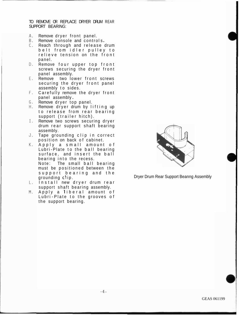
TO REMOVE OR REPLACE DRYER DRUM REAR SUPPORT BEARING:
Remove d r y e r f r o n t pane l . Remove conso le and c o n t r o l s . Reach t h r o u g h and r e l e a s e drum b e l t f r o m i d l e r p u l l e y t o r e l i e v e t e n s i o n on t h e f r o n t pane l . Remove f o u r u p p e r t o p f r o n t screws s e c u r i n g t h e d r y e r f r o n t panel assembly. Remove two l o w e r f r o n t screws s e c u r i n g t h e d r y e r f r o n t p a n e l assembly t o s ides . C a r e f u l l y remove t he d r y e r f r o n t panel assembly . Remove d r y e r t o p pane l . Remove d r y e r drum by l i f t i n g up t o r e l e a s e f r o m r e a r b e a r i n g suppor t ( t r a i l e r h i t c h ) . Remove two screws secur ing d r y e r drum r e a r suppor t s h a f t bea r i ng assembly. Tape g r o u n d i n g c l i p i n c o r r e c t p o s i t i o n on back o f cab ine t . A p p l y a s m a l l a m o u n t o f L u b r i - P l a t e t o t h e b a l l b e a r i n g I
', s u r f a c e , and i n s e r t t h e b a l l b e a r i n g i n t o t h e recess. N o t e : The s m a l l b a l l b e a r i n g
'$I must be p o s i t i o n e d between t h e s u p p o r t b e a r i n g a n d t h e g round ing c l i p .
% Dryer Drum Rear Support Beanng Assembly
I n s t a l l new d r y e r d r u m r e a r suppor t s h a f t b e a r i n g assembly. A p p l y a 1 i b e r a l a m o u n t o f L u b r i - P l a t e t o t h e g r o o v e s o f t h e suppor t bear ing .
GEAS 061199

I DRYER D R I V E HOTOR
The d r y e r d r i v e m o t o r i s a s i n g l e speed d u a l s h a f t , 1725 r .p .m . , 1/8 h . p . m o t o r , r a t e d a t 120 v o l t , 60 hz . An i n t e r n a l o v e r l o a d p r o t e c t o r i s b u i l t i n t o t h e m o t o r and w i l l open d u e t o e x c e s s i v e t e m p e r a t u r e r i s e and /o r e x c e s s i v e c u r r e n t . I f t h e o v e r l o a d p r o t e c t o r opens , a l l d r y e r o p e r a t i o n s w i l l s t o p . The m o t o r p r o t e c t o r i s s e l f - r e s e t t i n g and may t a k e as l o n g as 30 seconds t o r e s e t .
The d r y e r d r i v e m o t o r has a m u l t i p l e t e r m i n a l , snap-on, e l e c t r i c a l w i r i n g c o n n e c t o r b l o c k .
The c e n t r i f u g a l s w i t c h i n t h e d r y e r MOTOR M o u N n N G CLAMPS DUNE PULLEY
m o t o r p e r f o r m s t h r e e f u n c t i o n s . When t h e m o t o r i s a t r e s t , a s i n g l e - p o l e , d o u b l e t h r o w ( s p d t )
I c o n t a c t c l o s e s a c i r c u i t t o t h e m o t o r s t a r t w i n d i n g s . When t h e m o t o r i s s t a r t e d , p o w e r i s m o m e n t a r i l y s u p p l i e d t o t h e m o t o r t h r o u g h t h e p u s h - t o - s t a r t s w i t c h . As t h e t h e m o t o r comes t o speed, t h e ( s p d t ) c o n t a c t d i s c o n n e c t s t h e s t a r t w i n d i n g and s u p p l i e s power t o t h e r u n w i n d i n g . T h i s p r o v i d e s a h o l d i n g c i r c u i t t o keep t h e m o t o r o p e r a t i n g a f t e r t h e m o m e n t a r y p u s h - t o - s t a r t s w i t c h i s r e l e a s e d . As t h e m o t o r s w i t c h o p e r a t e s , a s e c o n d s e t o f c o n t a c t s c l o s e s a c i r c u i t t o t h e h e a t i n g e l e m e n t . T h i s p o r t i o n o f t h e m o t o r s w i t c h p r e v e n t s t h e h e a t e r f r o m o p e r a t i n g u n t i l t h e m o t o r i s o p e r a t i n g a t n o r m a l s p e e d . T h e m o t o r s t a r t s w i t c h i s n o t r e p l a c e a b l e .
GEAS 061200

TO R E M O V E OR REPLACE DRYER DRIVE MOTOR:
D i s c o n n e c t Laundry Cen te r f rom e l e c t r i c a l supply . Remove d r y e r f r o n t access/safety pane l . Remove conso le and c o n t r o l s . Reach t h r o u g h and r e l e a s e drum b e l t f r o m i d l e r p u l l e y t o r e l i e v e t e n s i o n on t h e f r o n t pane l . Remove two l o w e r f r o n t s c rews s e c u r i n g t h e d r y e r f r o n t pane l assembly t o s i d e pane ls . Remove f o u r u p p e r t o p f r o n t screws secu r i ng t h e d r y e r f r o n t panel assembly. C a r e f u l l y remove t h e d r y e r f r o n t panel assembl y . Remove d r y e r t o p pane l . Remove d r y e r drum by l i f t i n g up t o r e l e a s e f r o m r e a r b e a r i n g suppor t ( t r a i l e r h i t c h ) . Remove two screws s e c u r i n g t h e exhaust ven t elbow t o t he b lower hous ing . Remove s i x screws s e c u r i n g t h e d r y e r f r o n t b l o w e r h o u s i n g t o t h e r e a r b lower hous ing. Loosen t h e hex b o l t secur ing t h e b l o w e r wheel , and s l i d e b l owe r wheel o f f d r i v e motor s h a f t . Remove t h r e e screws secu r i ng t h e r e a r b lower hous ing t o t h e d r i v e motor c r a d l e . Re lease t h e e l e c t r i c a l w i r i n g c o n n e c t o r b l o c k t o t h e d r i v e moto r . Remove two clamps s e c u r i n g t h e d r i v e motor t o mount ing c r a d l e . Remove t h e d r y e r d r i v e m o t o r b e l t p u l l e y (p ress on f i t , f l u s h w i t h end o f motor s h a f t . ) I n s t a l l new d r y e r d r i v e motor . Reverse procedure t o reassemble.
GEAS 061201

DRYER DRUM DRIVE BELT
T h e d r y e r d r u m d r i v e b e l t i s a neoprene, f i b e r g l a s s , and n y l o n t i r e ' c o r d r e i n f o r c e d f l a t d r i v e b e l t . The d r y e r drum d r i v e be1 t i s d r i v e n b y t h e d r y e r d r i v e m o t o r p u l l e y a r o u n d t h e d r y e r d r u m . P r o p e r t e n s i o n i s m a i n t a i n e d b y an i d l e r p u l l e y and arm assembly .
TO REMOVE OR REPLACE DRYER DRUM DRIVE BELT:
MOTOR MOUNTING CLAMPS DRNE PULLEY
h I
A. Remove d r y e r f r o n t access pane l and s a f e t y c o v e r .
B. Reach t h r o u g h and r e l e a s e drum b e l t f r o m i d l e r p u l l e y t o r e l i e v e t e n s i o n o n t h e f r o n t p a n e l .
C . Remove t w o l o w e r f r o n t s c r e w s s e c u r i n g t h e d r y e r f r o n t p a n e l assembly t o s i d e p a n e l s .
D. Remove f o u r u p p e r t o p f r o n t sc rews s e c u r i n g t h e d r y e r f r o n t pane l assembly .
E . C a r e f u l l y remove t h e d r y e r f r o n t p a n e l assembly .
F . Remove d r y e r drum by l i f t i n g up t o r e l e a s e f r o m r e a r b e a r i n g s u p p o r t ( t r a i l e r h i t c h ) .
G . I n s t a l l new d r y e r d r u m d r i v e be1 t .
H. Reverse p r o c e d u r e t o reassemble . I I
IDLER ASSEMBLY I The i d l e r a s s e m b l y c o n s i s t s o f an i d l e r arm, a p u l l e y , and a s p r i n g t o m a i n t a i n c o n s t a n t t e n s i o n o n t h e d r i v e b e l t f o r p r o p e r d r u m speed. The i d l e r arm b r a c k e t has a key h o l e s l o t and moun ts o v e r a s t u d on t h e r e a r o f t h e d r i v e m o t o r c r a d l e .
/ I I IDLER PULLEY WASHER RETAINER RING
Fiaure G2 Dryer Drive Motor. Belt. Idler Assemblv
and Blower Wheel Assembly
GEAS 061202

DRYER E L E C T R I C A L COMPONENTS T E S T AND REPAIR
PUSH TO START DOOR SWITCH:
The p u s h t o s t a r t d o o r s w i t c h i s a s i n g l e p o l e , s i n g l e t h r o w n o r m a l l y open s w i t c h mounted i n t h e c o n t r o l p a n e l . The u s e r m o m e n t a r i l y p r e s s e s t h e s w i t c h b u t t o n t o a c t u a t e t h e d r y e r d r i v e m o t o r .
T h e d o o r s w i t c h i s a s i n g l e p o l e s i n g l e t h r o w n o r m a l l y open s w i t c h m o u n t e d i n t h e d r y e r f r o n t p a n e l . I t i t i s a c t u a t e d by t h e d r y e r d o o r .
B o t h s w i t c h e s a r e n o r m a l l y o p e n . They a r e i n s e r i e s w i t h each o t h e r , and a r e connec ted i n t h e h o t s i d e o f t h e l i n e be tween t h e t i m e r and t h e d r i v e m o t o r . N e i t h e r m o t o r w i l l o p e r a t e u n t i l t h e d r y e r d o o r i s c l o s e d a n d t h e s t a r t s w i t c h i s m e m e n t a r i 1 y d e p r e s s e d ( c l o s e d ) b y t h e u s e r . The push t o s t a r t s w i t c h i s a l s o i n p a r a l l e l w i t h t h e c e n t r i f u g a l s t a r t s w i t c h i n t h e m o t o r . When t h e m o t o r i s u p t o s p e e d , t h e c e n t r i f u g a l s w i t c h m a i n t a i n s t h e c i r c u i t m o m e n t a r i l y e s t a b l i s h e d b y d e p r e s s i n g t h e p u s h t o s t a r t s w i t c h .
PUSH TO START TESTING
A. R e m o v e d r y e r f r o n t s e r v i c e p a n e l .
B. Remove f o u r screws s e c u r i n g t h e c o n s o l e and c o n t r o l s a s s e b l y t o s i d e p a n e l .
C . D i s c o n n e c t e l e c t r i c a l w i r i n g c o n n e c t o r b l o c k s .
D. L a y c o n s o l e a n d c o n t r o l s assembly on a p r o t e c t e d s u r f a c e .
E . Remove w i r e s f r o m push t o s t a r t s w i t c h a n d c o n n e c t o h m m e t e r a c r o s s t e r m i n a l s .
F . P r e s s b u t t o n , ohmmeter s h o u l d show c o n t i n u i t y .
G. I f n o c o n t i n u i t y , r e p l a c e push t o s t a r t s w i t c h .
GEAS 061203

DRYER TIMER
The d r y e r t i m e r p r i m a r i l y c o n t r o l s t h e l e n g t h o f t i m e t h e d r y e r o p e r a t e s . The t i m e r c o n s i s t s o f a s e r i e s o f cams and s w i t c h e s d r i v e n by a synchronous m o t o r . I t i s e t by r o t a t i n g t h e k n o b a n d d i a l c l o c k w i s e . T h e r e i s n o p u s h p u l l s w i t c h i n t h e d r y e r t i m e r . T h e t i m e r m o t o r o p e r a t e s on 120 v o l t s , 60 h z . I n t h e t i m e d c y c l e , t h e t i m e r m o t o r i s c o n t r o l l e d b y t h e i n t e r n a l c o n t a c t s o f t h e t i m e r . I n t h e a u t o m a t i c c y c l e , t h e t i m e r mo to r i s c o n t r o l l e d b y b a c k s i d e c o n t a c t f i2 o f t h e h e a t c o n t r o l t h e r m o s t a t .
DRYER TIMER MOTOR TESTING:
I f t h e t i m e r does n o t advance i n t h e t i m e d c y c l e ( s ) , d i s c o n n e c t t h e t i m e r m o t o r l e a d s f r o m t h e t i m e r a n d / o r o t h e r t e r m i n a l s , and connec t them t o a f u s e d t e s t c o r d . P l u g t e s t c o r d i n t o a 1 2 0 v o l t o u t l e t . I f t h e t i m e r d o e s n o t a d v a n c e , r e p l a c e t i m e r .
FABRIC TEMPERATURE SELECTOR SNITCH
T h e f a b r i c t e m p e r a t u r e s e l e c t o r s w i t c h i s e i t h e r a r o t a r y o r a push b u t t o n s w i t c h w h i c h a l l o w s t h e u s e r t o s e l e c t t h e p r o p e r t e m p e r a t u r e f o r e a c h c l o t h e s l o a d . T h i s i s accomp l i shed i n c o n j u n c t i o n w i t h t h e h e a t c o n t r o l t h e r m o s t a t . A l l f a b r i c t e m p e r a t u r e s e l e c t o r s w i t c h e s have a s e t o f c o n t a c t s w h i c h d i r e c t l y c o n t r o l p o w e r t o t h e d r y e r g a s b u r n e r . These c o n t a c t s a r e open f o r n o h e a t d r y i n g . Some f a b r i c s e l e c t o r s w i t c h e s h a v e a n a d d i t i o n a l c o n t a c t w h i c h s u p p l i e s c u r r e n t t o t h e c o n t r o l t h e r m o s t a t b i a s i n g h e a t e r as f o l l o w s :
GEAS 061204

SAFETY THERMOSTAT
T h e s a f e t y t h e r m o s t a t i s s n a p a c t i o n , a u t o m a t i c r e s e t , e n c l o s e d d i s c t y p e and p r o v i d e s p r o t e c t i o n f o r t h e d r y e r i n t h e e v e n t o f a b l o c k e d e x h a u s t , c l o g g e d 1 i n t screen, o r ove r l oaded drum. I t i s m o u n t e d o n t h e t o p s i d e o f t h e h e a t e r hous ing , i n t h e a i r stream, and senses heat b u i l d up.
SAFETY THERMOSTAT TESTING:
A. D i sconnec t U n i t f rom e l e c t r i c a l supply .
B. Remove d r y e r t o p panel . C . Remove l e a d s t o t h e s a f e t y
thermos ta t . D. Connect ohmmeter ac ross s a f e t y
thermos ta t t e r m i n a l s . E . T h e o h m m e t e r s h o u l d s h o w
c o n t i n u i t y b e t w e e n t h e t w o t h e r m o s t a t t e r m i n a l s a t r oom temperature.
F . To check f o r s t u c k c o n t a c t s i n t h e thermos ta t , r u n t he d r y e r on h i g h heat w i t h t h e exhaust d u c t compl e t l y b locked. The con tac t s m u s t b e o p e n w i t h i n t h r e e minutes.
HEAT CONTROL THERMOSTAT
The h e a t c o n t r o l t h e r m o s t a t i s a s i n g l e po le , s i n g l e throw, n o r m a l l y c l o s e d ( b u t opens on t e m p e r a t u r e r i s e ) , b i - me ta l , snap a c t i o n sw i tch . I t o p e n s a n d c l o s e s i n t e r n a l c o n t a c t s t o c o n t r o l t h e tempera tu re o f t h e a i r f l o w i n g t h r o u g h t h e d r y e r . The c o n t r o l t h e r m o s t a t i s l o c a t e d i n t h e b lower housing and i s i n s e r i e s w i t h t h e gas b u r n e r . On some models t h e c o n t r o l t he rmos ta t has a l o w w a t t a g e b i a s i n g h e a t e r mounted c l o s e t o t h e b i - m e t a l . When t h e b i a s h e a t e r i s e n e r g i z e d , t h e b i - m e t a l h e a t s up more q u i c k l y and open t h e c i r c u i t t o t h e gas bu rne r a t a l o w e r d rum a i r t e m p e r a t u r e . Re fe r t o w i r i n g diagram f o r c o r r e c t i n f o r m a t i o n on s p e c i f i c model s .
GEAS 061205

HEAT CONTROL THERMOSTAT TESTING:
A. D i s c o n n e c t u n i t f r o m e l e c t r i c a l s u p p l y .
B. R e m o v e d r y e r f r o n t a c c e s s p a n e l s .
C . R e m o v e w i r e s f r o m t h e h e a t c o n t r o l t h e r m o s t a t t e r m i n a l s . Ohmmeter s h o u l d show c o n t i n u i t y b e t w e e n t e r m i n a l s a t r o o m t e m p e r a t u r e .
D. To c h e c k c u t - o u t t e m p e r t u r e s , i n s e r t a t h e r m o c o u p l e s e n s i n g l e a d i n t o t h e l i n t t r a p . A l l o w t h e d r y e r t o r u n l o n g enough t o p e r m i t t h e t h e r m o s t a t t o c y c l e 3 o r 4 t i m e s . T h e t e m p e r a t u r e a f t e r t h e t h i r d o r f o u r t h c y c l e s h o u l d compy w i t h t e m p e r a t u r e c h a r t .
HEAT CONTROL THERMOSTAT B I A S I N G HEATER.
A. D i s c o n n e c t u n i t f r o m e l e c t r i c a l s u p p l y I
B. Remove d r y e r f r o n t access p a n e l . C . Remove e l e c t r i c a l w i r i n g t o t h e
h e a t c o n t r o l t h e r m o s t a t b i a s i n g h e a t e r a n d c o n n e c t o h m m e t e r a c r o s s t e r m i n a l s .
D. Shou ld show 10,000 +- 10% ohms.
END OF CYCLE BUZZER
The e n d - o f - c y c l e b u z z e r sounds f o r a p p r o x i m a t e l y f i v e s e c o n d s a t t h e end o f any d r y i n g c y c l e , i n d i c a t i n g t o t h e u s e r t h a t t h e c l o t h e s s h o u l d be removed f r o m t h e d r y e r a t t h a t t i m e t o a v o i d w r i n k l i n g . A u t o D r y C y c l e h a s a 1 0 m i n u t e c o o l down p e r i o d as o p p o s e d t o t h e 6 m i n u t e c o o l down p e r i o d f o r t i m e d d r y . C o n t a c t W t o BL w i l l c l o s e , a l l o w i n g t h e c u r r e n t t o f l o w t h r o u g h t h e b u z z e r c o i l , t h e p u l s e r w i l l s l l o w t h e b u z z e r t o sound f o r f i v e seconds o f each 50 seconds o f a f i v e m i n u t e i n t e r v a l , a l e r t i n g t h e u s e r e v e r y 5 m i n u t e s w i t h t h e e n d - o f - c y c l e b u z z e r . The e n d - o f - c y c l e b u z z e r i s p a r t o f t h e d r y e r t i m e r .
GEAS 061206

DRYER DRIVE MOTOR TESTING:
The m o t o r , motor p r o t e c t o r , and c e n t r i f u g a l motor swi tch a r e t h e t h r e e components t h a t must function c o r r e c t l y in order f o r the motor t o r u n . To de te rmine t h e cause of a m o t o r t h a t i s n o t o p e r a t i n g c o r r e c t l y , i t i s n e c e s s a r y t o is01 a t e the re la ted components from t h e r e s t o f t h e c i r c u i t r y . The f o l l o w i n g s e r v i c e t e s t procedures a r e s u g g e s t e d t o h e l p l o c a t e a d e f e c t i v e component in t h e motor c i r c u i t .
Disconnect laundry c e n t e r from e l e c t r i c a l supply. Remove dryer access panels. Remove console and controls . Reach through and r e l e a s e drum b e l t f r o m i d l e r p u l l e y t o r e l i e v e t e n s i o n on t h e f r o n t panel. Remove two lower f r o n t screws secur ing t h e d r y e r f r o n t panel assembly t o s ide panels. Remove f o u r u p p e r t o p f r o n t screws secur ing the dryer f ron t panel. Carefully remove the dryer f ront assembly panel. Remove dryer top panel. Remove dryer drum by 1 i f t i n g u p t o r e l e a s e from r e a r b e a r i n g support . Disconnect a l l wires coming from the wiring harness t o the motor s t a r t switch. Do not disconnect the wires t h a t come from i n s i d e the motor i t s e l f . Connect a p r o p e r l y fused t e s t cord t o terminals 1 and 4 of the motor s t a r t s w i t c h . I f t h e motor r u n s , t h e problem i s in the dryer wiring o r con t ro l . I t i t does not r u n , c o n t i n u e t h e t e s t procedure.
The motor o v e r l o a d p r o t e c t o r i s n o t a v a i l a b l e as a replacement par t . I t will r e s e t when i t c o o l s down. Allow i t t o cool and recheck again.
GEAS 061207

I D R Y E R T I M E R
I T h e t i m e r m o t o r o p e r a t e s o n 120 v o l t s on 208/240 v o l t l a u n d r y u n i t s . I n t h e t i m e d c y c l e . t h e t i m e r m o t o r i s c o n n e c t e d t o o n e s i d e o f t h e p o w e r s u p p l y l i n e a n d n e u t r a l , p r o v i d i n g 120 v o l t s f o r o p e r a t i o n . I n t h e a u t o m a t i c c y c l e , t h e t i m e r m o t o r i s c o n n e c t e d a c r o s s t h e 208 /240 v o l t l i n e s , b u t i n s e r i e s w i t h a 4 .4k ohm d r o p p i n g r e s i s t o r , a q a i n p r o v i d i n q 1 2 0 v o l t s t o t h e
I t i m e r m o t o r .
I HEATER ASSEMBLY
The h e a t e r assembly, 208/240 v o l t s , 3400/4500 w a t t s , i s l o c a t e d between t h e r e a r ( o u t e r ) p a n e l and t h e drum b a c k p a n e l a n d i s s e c u r e d w i t h 4 screws. The h e a t e r i s an open c o i l t y p e h e a t e r made f r o m a c o n t i n u o u s c o i l o f r e s i s t a n c e w i r e a t t a c h e d t o a m e t a l s u p p o r t h o u s i n g w i t h ce ram ic s t a n d o f f s .
I SAFETY THERMOSTAT
The s a f e t y t h e r m o s t a t i s a s n a p a c t i o n , a u t o m a t i c r e s e t e n c l o s e d d i s c t y p e and p r o v i d e s p r o t e c t i o n f o r t h e d r y e r i n t h e e v e n t o f a b l o c k e d e x h a u s t , c l o g g e d l i n t s c r e e n , o r o v e r l o a d e d drum. I t i s m o u n t e d o n t h e t o p s i d e o f t h e h e a t e r h o u s i n g , i n t h e a i r s t ream, and senses h e a t b u i l d up.
H I TEMP THERMAL L I M I T E R FUSESTAT
The h i g h t e m p e r a t u r e t h e r m a l l i m i t e r i s a s i n g l e p o l e , s i n g l e t h r o w , t e m p e r a t u r e a c t i v a t e d f u s e s t a t , t h a t when t r i p p e d w i l l open t h e c i r c u i t t o t h e m o t o r p r e v e n t i n g t h e d r y e r f r o m o p e r a t i n g . T h e h i g h
I t e m p e r a t u r e t h e r m a l l i m i t e r f u s e s t a t
I c a n n o t be r e s e t . I t i s mounted on t h e t o p s i d e o f t h e h e a t e r h o u s i n g , i n t h e a i r s t r e a m and senses h e a t b u i l d up.
GEAS 061208

GAS COMPONENTS REPAIR
BURNER ASSEMBLY BURNER
The heat source for the gas dryer IS the bumer assembly shown below. The burner assemblv conslsts of a combination gas valve assembly. a bumer. and a burner tube. The burner comes from the factory s~zed and adlusted to deliver heat a t the rate of 20.000 B.T.U.'s per hour uslng natural gas. The burner assembly is mounted to the access shield located behind the dryer access panel.
WARNING: No other fuel should be used wtth the burner assembly unless properly modified by a qualified setwce technlctan.
COMBINATION GAS VALVE
The combination gas valve assembly lncludes two solenold shut-off valves. a gas pressure regulator. and a gas orifice assembled into a single cast body. The pressure regulator is factory set to maintain 3 112' of water column gas pressure at the onfice. The regulator is service adjustable. The two solenoid valves are In senes such that the gas flowing through the pressure regulator must pass through both valves to get to the ortlice and burner. The first solenoid valve is referred to as the split coil valve. The electrical coil which operates the valve IS
made up of two coils stacked in one housing. The upper holding coil is capable of holding the valve open but is not able to open the valve from its normally closed position. To open the valve. the lower booster coil is energlzed. The second solenotd valve is called the secondary valve. This valve is operated by a single electrical corl which opens the valve and holds it open when the gas bumer is In operation. The orifice is a precisely drilled brass plug screwed into the outlet port of the combination valve. The onfice extends into the bumer. The combination of regu- lated pressure and orifice size provides the proper vol- ume of gas for the heat rating of the burner.
The bumer~s a short metal tube tn whtch atr IS m~xed wtth the gas fuel to prov~de a combustable mtxture whtch wtll bum dean. wtthout smoke or noxlous fumes An adlust- able alr shutter at the Inlet controls the amount of mlxlno alr The shutter IS preset and does not ordlnanlv requlre adlustmen1 A flame spreader extends out over the open end of the bumer Thls IS the area where combustton of the fuellalr mtxture takes place
IGNITOR
Ignition of the fueliair mixture is accomplished throuah the use of a silicon carbide ign~tor (glow-bar1 The ign~tor is mounted to the burner at an anale wtth the alow-bar extr ded into the flamearea. Silicon carbtde is a matertal capable of withstanding very hiah temperature, but ~t ts fragtle and susceptable to contamtnahon from skin 011s and other toretgn material. It must be handled w~th care. using theinsulated support. Electrically, sllicon carbide 1s a thermtstor, i.e., its electrical reststance chanaes Ide- creases) as its temperature rlses. When energlzed. the ignitor glow-bar beglns to heat wtth its reststance steadlly decreasing reaching a temperature of 1800 F.
SENSOR
This device is located on the side of the burner tube It consists of a thermostatically operated single pole. slngle throw (SPST). normally closed INC) swttch. mounted over a window cut Into the burner tube. The sensor senses the intense heat. radiating Initially from the Ignl- tor. and then from the burner flame. The sensor opens within 15 to 90 seconds after the ignitor reaches tgn~t~on temperature. The reaction tlme is longest durlng a cold start-up.
SENSOR
TUBE
GEAS 061209

GE
AS 061210

NOTES
GEAS 061211