techniques for measuring the electrical resistivity of ... · techniques for measuring the...
TRANSCRIPT

© Copyright 2010 Keithley Instruments, Inc.
A G R E A T E R M E A S U R E O F C O N F I D E N C E
Techniques for Measuring the Electrical
Resistivity of Bulk Materials
Mary Anne Tupta
November 18, 2010

© Copyright 2010 Keithley Instruments, Inc.
A G R E A T E R M E A S U R E O F C O N F I D E N C E | w w w . k e I t h l e y . c o m
2
Resistivity Measurement Overview
• Definition of electrical resistivity of a material.
• Methods for making resistivity measurements of conductors,
insulators, and semiconductors.
• Key considerations for selecting equipment for measuring
resistivity.
• Sources of measurement errors and ways to optimize resistivity
measurements

© Copyright 2010 Keithley Instruments, Inc.
A G R E A T E R M E A S U R E O F C O N F I D E N C E | w w w . k e I t h l e y . c o m
3
What is the Electrical Resistivity of a Material?
The electrical resistance of a material……
• is a basic material property
• defines how well the material will conduct an electric current
• is a common electrical measurement.
Ohm’s law relates the current (I) and the applied voltage (V) to the
material resistance (R) as follows:
V=IR

© Copyright 2010 Keithley Instruments, Inc.
A G R E A T E R M E A S U R E O F C O N F I D E N C E | w w w . k e I t h l e y . c o m
4
What is the Electrical Resistivity of a Material?
Electrical Resistivity = longitudinal electrical resistance of a uniform
rod of unit length and unit cross-sectional area:
L
AR
V
L
A
Current Source
Voltmeter
ρ = resistivity (Ω-cm)
R = resistance: V/I (Ω)
A = cross-sectional area of
sample (cm2)
L = distance between two
leads of voltmeter (cm)

© Copyright 2010 Keithley Instruments, Inc.
A G R E A T E R M E A S U R E O F C O N F I D E N C E | w w w . k e I t h l e y . c o m
5
Typical Resistivity Values
The electrical resistivities of solid materials span over many magnitudes.
Three classifications of materials based on their resistivities:
Classification Type of Electrical
Conductor
Typical Resistivities
Metals Good electrical
conductors
10-6 Ω-cm
Insulators Low electrical
conductivity
109 to 1020 Ω-cm
Semiconductors Intermediate levels of
conductivity
10-3 to 107 Ω-cm
© Copyright 2010 Keithley Instruments, Inc.
A G R E A T E R M E A S U R E O F C O N F I D E N C E | w w w . k e I t h l e y . c o m
6
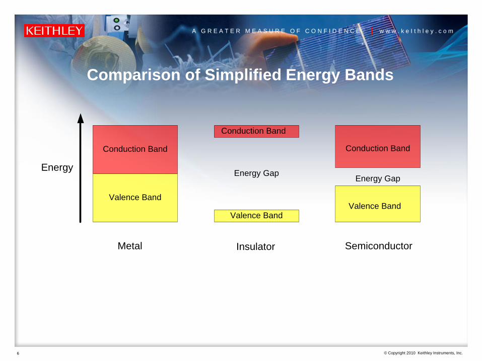
Comparison of Simplified Energy Bands
Conduction Band
Conduction Band
Conduction Band
Valence Band
Valence BandValence Band
Metal Insulator Semiconductor
Energy GapEnergy Gap
Energy

© Copyright 2010 Keithley Instruments, Inc.
A G R E A T E R M E A S U R E O F C O N F I D E N C E | w w w . k e I t h l e y . c o m
7
Measuring the Resistivity of
Conductors:Metals and Superconductors (very low resistance)
Graphene and other Nanomaterials
(low voltage and low power - use same techniques)

© Copyright 2010 Keithley Instruments, Inc.
A G R E A T E R M E A S U R E O F C O N F I D E N C E | w w w . k e I t h l e y . c o m
8
Measuring the Resistivity of Conductors
V
L
t
w
Voltmeter
Current Source
Sample
Basic Test Procedure:
1. Source current (I) through the
sample using one pair of leads.
2. Measure the voltage drop (V)
across a second pair of leads a
known distance (L) apart.
3. Calculate the resistivity (ρ) of
the sample using the cross-
sectional area (A=wt) and the
distance between the voltmeter
leads.
cmL
wt
I
V

© Copyright 2010 Keithley Instruments, Inc.
A G R E A T E R M E A S U R E O F C O N F I D E N C E | w w w . k e I t h l e y . c o m
9
Sources of Error When Measuring Low Resistance
• Test Lead Resistance
• Thermoelectric Voltages
• Low Frequency Noise
• External Noise Sources
• Johnson Noise
• Voltmeter Not Sensitive Enough

© Copyright 2010 Keithley Instruments, Inc.
A G R E A T E R M E A S U R E O F C O N F I D E N C E | w w w . k e I t h l e y . c o m
10
Eliminate Lead Resistance by Using the 4-Wire Method
V
RLeadRLead
RSample
I
V
RLeadRLead
RSample
I
Measured Resistance:
VM/I = RSample + 2RLead
Measured Resistance:
VM/I = RSample
2-Wire Method 4-Wire Method

© Copyright 2010 Keithley Instruments, Inc.
A G R E A T E R M E A S U R E O F C O N F I D E N C E | w w w . k e I t h l e y . c o m
11
Thermoelectric Voltages
Current Source
Sample – Metal B
V
Voltmeter
Copper Test Leads
Metal A
Thermoelectric voltages are generated when dissimilar metals (Metal A
and Metal B) in the circuit are at different temperatures (T1 and T2).
V
Voltmeter
Copper Test Leads
Metal A
T1 T2Sample
Metal B
Temperature Gradient

© Copyright 2010 Keithley Instruments, Inc.
A G R E A T E R M E A S U R E O F C O N F I D E N C E | w w w . k e I t h l e y . c o m
12
Ways to Reduce Thermoelectric Voltages
• Construct test circuits using the same materials for interconnects.
• Minimize temperature gradients within the test circuit
• Allow the test equipment to warm up
• Use an offset compensation method

© Copyright 2010 Keithley Instruments, Inc.
A G R E A T E R M E A S U R E O F C O N F I D E N C E | w w w . k e I t h l e y . c o m
13
Use the Current Reversal Method
to Eliminate Voltage Offsets (VEMF)
IRIRVIRVVV
V EMFEMFMMM
2
)(
2
Measurement with Positive Polarity Measurement with Negative Polarity
VM+ = VEMF + IR VM- = VEMF - IR
Voltage Measurement:
VEMF
R
VM+
VEMF
R
VM-I+ I-

© Copyright 2010 Keithley Instruments, Inc.
A G R E A T E R M E A S U R E O F C O N F I D E N C E | w w w . k e I t h l e y . c o m
14
Use the Delta Mode Method to Eliminate Voltage Offsets
and Noise
The Delta method consists of
alternating the current source
polarity and using a moving
average of voltage readings to
calculate the resistance.
Averaging reduces the noise
bandwidth and therefore the noise.

© Copyright 2010 Keithley Instruments, Inc.
A G R E A T E R M E A S U R E O F C O N F I D E N C E | w w w . k e I t h l e y . c o m
15
External Noise Sources
• External Noise Sources = interferences created by motors, computer
screens, or other electrical equipment
• Control these External Noise Sources by:
– Shielding and filtering
– Remove or turn-off the noise source
– When using DC instruments, integrate each measurement for an integer number of
power line cycles. The line cycle noise will “average out” when the integration time
is equal to an integration number of power line cycles.

© Copyright 2010 Keithley Instruments, Inc.
A G R E A T E R M E A S U R E O F C O N F I D E N C E | w w w . k e I t h l e y . c o m
16
Johnson Noise
• Johnson Noise – places a fundamental limit on resistance measurements.
• In any resistance, thermal energy produces the motion of charged particles. This charge movement results in Johnson noise.
• The formula for the voltage noise generated:
where k=Boltzmann’s constant, T= temp in K,
B=noise bandwidth in Hz, R=resistance of sample in ohms
• Reduce by:
1. reduce the measurement bandwidth –digital filtering (averaging readings) or analog filtering
2. reduce temperature of the device
3. reduce the sample resistance (usually not practical)
kTRBVrms 4

© Copyright 2010 Keithley Instruments, Inc.
A G R E A T E R M E A S U R E O F C O N F I D E N C E | w w w . k e I t h l e y . c o m
17
Use a Nanovoltmeter to Measure Voltage Drops
When measuring the resistances of conductors or other low power
materials, very small voltages are measured, typically in the microvolt and
nanovolt range.
To measure these very small voltage drops, use a sensitive voltmeter such
as a nanovoltmeter.Verify the product specifications to
make sure the measurement
resolution and accuracy will be
able to perform the sensitive
measurement of your application.
Model 2182A Nanovoltmeter

© Copyright 2010 Keithley Instruments, Inc.
A G R E A T E R M E A S U R E O F C O N F I D E N C E | w w w . k e I t h l e y . c o m
18
Review of Measurement Considerations for Measuring
the Resistivity of Conductors
• Make a 4-wire measurement to eliminate the lead resistance from affecting the measurement accuracy
• Use an offset compensation technique to eliminate voltage offsets and reduce noise: Current Reversal Method or Delta Method
• Eliminate external noise sources and use line cycle integration.
Continued……
V
L
Voltmeter
Current Source
Sample

© Copyright 2010 Keithley Instruments, Inc.
A G R E A T E R M E A S U R E O F C O N F I D E N C E | w w w . k e I t h l e y . c o m
19
Continued…..Review of Measurement Considerations
• Reduce Johnson noise by reducing the
measurement bandwidth, averaging
readings, and reducing the temperature
of the sample
• Use a sensitive voltmeter, such as a
nanovoltmeter, to measure the low
voltages
• Use a low noise, bipolar current source
that can perform current reversals
Model 2182A
Nanovoltmeter
kTRBVrms 4
Model 6221 AC
+ DC Current
Source
Model 6220 DC
Current Source

© Copyright 2010 Keithley Instruments, Inc.
A G R E A T E R M E A S U R E O F C O N F I D E N C E | w w w . k e I t h l e y . c o m
20
Measuring the Resistivity of Insulators
(high resistance)

© Copyright 2010 Keithley Instruments, Inc.
A G R E A T E R M E A S U R E O F C O N F I D E N C E | w w w . k e I t h l e y . c o m
21
Resistivity Measurements of Insulators
The resistance of an insulator
is measured by:
1. Applying a voltage to the
sample for a specified
time period
2. Measuring the resulting
current
3. Calculating the resistivity
using Ohm’s Law and
geometrical considerations
A
Sample
Resistance
AmmeterVoltage
Source
I
R
V
I
VR

© Copyright 2010 Keithley Instruments, Inc.
A G R E A T E R M E A S U R E O F C O N F I D E N C E | w w w . k e I t h l e y . c o m
22
Volume Resistivity of Insulator
t
A
I
V
Test Procedure for Volume Resistivity:
1. Please sample between 2 electrodes of area (A).
2. Apply potential difference (V) between the 2
electrodes.
3. Wait specified time (60 seconds) and measure
current (I) using sensitive ammeter.
4. Calculate resistivity based on the area of the
electrodes and thickness of the sample (t). Units
are Ω-cm.
Volume Resistivity is a measure of the leakage
current directly through a material.
HI
LO
HI
LO
Voltage
Source
Electrode
Sample
t
A

© Copyright 2010 Keithley Instruments, Inc.
A G R E A T E R M E A S U R E O F C O N F I D E N C E | w w w . k e I t h l e y . c o m
23
Surface Resistivity of Insulator
L
w
I
V
Surface Resistivity is defined as the electrical resistance of the surface of an
insulator.
Test Procedure for Surface Resistivity:
1. Place two electrodes a known distance (L) apart on sample.
2. Apply potential difference (V) between electrodes.
3. Wait specified time and measure current (I) with ammeter.
4. Calculate resistivity using width (w) of material and distance (L) between the
electrodes. The units are ohms or ohms per square.
ElectrodeHI
LO
HI
LO
wSample
L
A
I

© Copyright 2010 Keithley Instruments, Inc.
A G R E A T E R M E A S U R E O F C O N F I D E N C E | w w w . k e I t h l e y . c o m
24
Sources of Error When Measuring High Resistance
• Improper Measurement Instrumentation
• Electrification Time
• Test Voltage
• Background Currents
• Electrodes and Geometrical Considerations
• Electrostatic Interference
• Humidity

© Copyright 2010 Keithley Instruments, Inc.
A G R E A T E R M E A S U R E O F C O N F I D E N C E | w w w . k e I t h l e y . c o m
25
Use Sensitive Ammeter and Proper Cabling
Measuring the resistance of insulators usually involves measuring current in the
1E-9 and 1E-12 current range.
When measuring very small current, <100nA, it is important to use a sensitive
ammeter, such as an electrometer or picoammeter.
Electrometers and picoammeters have sub-picoamp (1E-12) sensitivity.
Model 6517B Electrometer/
Voltage Source:
The 6517B has 1E-15 A
Sensitivity!

© Copyright 2010 Keithley Instruments, Inc.
A G R E A T E R M E A S U R E O F C O N F I D E N C E | w w w . k e I t h l e y . c o m
26
Time Dependency of High Resistance Measurement
250V Step Response of Antistatic Bag
•Apply 250V
•Wait 60s
•Measure Current
•Calculate Resistivity
At 5 s, current=
1.5x10⁻¹⁰
At 60 s, current=
2.5x10⁻¹²
© Copyright 2010 Keithley Instruments, Inc.
A G R E A T E R M E A S U R E O F C O N F I D E N C E | w w w . k e I t h l e y . c o m
27
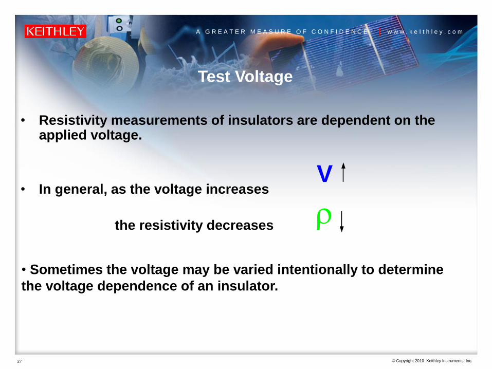
Test Voltage
• Resistivity measurements of insulators are dependent on the applied voltage.
• In general, as the voltage increases
the resistivity decreases
V
• Sometimes the voltage may be varied intentionally to determine
the voltage dependence of an insulator.

© Copyright 2010 Keithley Instruments, Inc.
A G R E A T E R M E A S U R E O F C O N F I D E N C E | w w w . k e I t h l e y . c o m
28
Background Currents
When measuring very high resistances, background currents can cause
erroneous readings. Background may be due to:
•charge stored in the material
•static or triboelectric charge
•piezoelectric effects
Background currents can be equal or greater than the current stimulated by the
applied voltage.
If background current is same polarity as measured current, then resultant
current reading will be much higher than the true value.
If background current is the opposite polarity, these unwanted currents may
cause a reverse polarity current reading. This can cause the calculated
resistance to be negative!
© Copyright 2010 Keithley Instruments, Inc.
A G R E A T E R M E A S U R E O F C O N F I D E N C E | w w w . k e I t h l e y . c o m
29
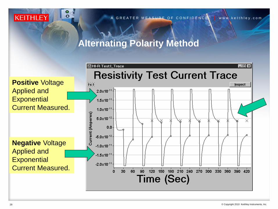
Alternating Polarity Method
Positive Voltage
Applied and
Exponential
Current Measured.
Negative Voltage
Applied and
Exponential
Current Measured.

© Copyright 2010 Keithley Instruments, Inc.
A G R E A T E R M E A S U R E O F C O N F I D E N C E | w w w . k e I t h l e y . c o m
30
Electrodes
Electrodes for use on an insulating material:
• Has good contact to the material: paint on electrodes or use flat metal plates with conductive rubber
• Should be much lower resistance than the sample and should not contaminate the sample
• Enables easy calculation of resistivity from the geometrical considerations
Rt
AelectrodeWhere:
ρ=Volume Resistivity
A=area of electrode on sample
t=thickness of sample
R=measured resistance V/I

© Copyright 2010 Keithley Instruments, Inc.
A G R E A T E R M E A S U R E O F C O N F I D E N C E | w w w . k e I t h l e y . c o m
31
Volume Resistivity with the Model 8009 Resistivity Test
Fixtures
Model 8009
Resistivity Test Chamber
Test
Sample
A
Voltage
SourceAmmeter
Guard0V
Electrodes
HI
LO
HI
LO
Volume resistivity is a measure of the leakage
current through the material, between the top
electrode and center bottom electrode. The
outside ring electrode is guard.
Top Electrode
Center Electrode
Ring

© Copyright 2010 Keithley Instruments, Inc.
A G R E A T E R M E A S U R E O F C O N F I D E N C E | w w w . k e I t h l e y . c o m
32
Surface Resistivity with the Model 8009
Test
Sample
AAmmeter
Guard0VElectrodes
HI
LO
HI
LO
R
The Surface Resistivity is
measured by placing two
electrodes on the surface of the
test sample, applying a potential
difference between them, and
measuring the resulting current.
Notice the surface resistivity (R)
is measured between the bottom
Center Electrode and the Ring
Electrode.

© Copyright 2010 Keithley Instruments, Inc.
A G R E A T E R M E A S U R E O F C O N F I D E N C E | w w w . k e I t h l e y . c o m
33
Model 65 High Resistivity Measurement Package
8009
Resistivity
Test Fixture
6517B Electrometer/
Voltage Source
6524
Software

© Copyright 2010 Keithley Instruments, Inc.
A G R E A T E R M E A S U R E O F C O N F I D E N C E | w w w . k e I t h l e y . c o m
34
Electrostatic Interference and Shielding
Shield
HI
LO
Voltage
SourceAmmeter
HI
LO
Sample
Connect Shield to LO terminal of Picoammeter or Electrometer

© Copyright 2010 Keithley Instruments, Inc.
A G R E A T E R M E A S U R E O F C O N F I D E N C E | w w w . k e I t h l e y . c o m
35
Review of Measurement Considerations for Measuring
the Resistivity of Insulators
1. Use a picoammeter or electrometer for low current measurements
2. Use the same electrification time for each test to compare results
3. Use the same applied voltage for test comparisons
4. Use the Alternating Polarity Technique to reduce the effects of background currents
5. Use proper electrodes and take geometrical considerations into account
6. Use electrostatic shielding to avoid errors due to electrostatic interference
7. Use an environmentally controlled room
Model 8009
Model 6517B

© Copyright 2010 Keithley Instruments, Inc.
A G R E A T E R M E A S U R E O F C O N F I D E N C E | w w w . k e I t h l e y . c o m
36
Measuring the Resistivity of
Semiconductors

© Copyright 2010 Keithley Instruments, Inc.
A G R E A T E R M E A S U R E O F C O N F I D E N C E | w w w . k e I t h l e y . c o m
37
Measuring Resistivity of Semiconductors
The two most common methods for measuring the resistivity of
semiconductor materials are the
• Four-Point Collinear Probe Method
• van der Pauw Resistivity Method
Both of these methods use a 4-wire method to eliminate both the
lead resistance and the contact resistance from affecting
measurement accuracy.
Photo courtesy of Lucas Signatone

© Copyright 2010 Keithley Instruments, Inc.
A G R E A T E R M E A S U R E O F C O N F I D E N C E | w w w . k e I t h l e y . c o m
38
4-Point Collinear Probe Method
tkI
V
2ln
Test Procedure:
1. Place probes in center of wafer.
2. Source current from probes 1 to 4.
3. Measure voltage between probes 2 and 3.
4. Calculate resistivity:
Where:
ρ= volume resistivity (ohm-cm)
V=voltage measured between 2 and 3
I=source current (A)
t = sample thickness (cm)
k=correction factor
V
4-Point
Collinear
Probe1 2 3 4
Source Current
From 1 To 4
Measure
Voltage
Between 2
And 3
HI
HI LO
LO
Wafer
© Copyright 2010 Keithley Instruments, Inc.
A G R E A T E R M E A S U R E O F C O N F I D E N C E | w w w . k e I t h l e y . c o m
39
Sources of Measurement Error
1. Lead and contact resistance
2. Voltage offsets (use current reversal method to reduce)
3. Instrumentation
4. Issues with high resistance materials

© Copyright 2010 Keithley Instruments, Inc.
A G R E A T E R M E A S U R E O F C O N F I D E N C E | w w w . k e I t h l e y . c o m
40
Test Set-Up Showing Circuit Resistances
V
1 2 3 4
Source Current
Measure Voltage
Between 2 And 3
HI
HI LO
LO
RL1 RL2 RL3RL4
RC1
RS2RS1 RS3
V
RC2 RC3 RC4
RL=Lead Resistance
RC=Contact Resistance
RS=Semiconductor Resistance
Only the voltage drop due to RS2 is
measured by the voltmeter.

© Copyright 2010 Keithley Instruments, Inc.
A G R E A T E R M E A S U R E O F C O N F I D E N C E | w w w . k e I t h l e y . c o m
41
Instrumentation for Mid-Range Resistances
(100mohm to <1Mohm)
Use a standard DC current source (bipolar to perform current reversals) to
force the current and a DMM to measure the voltage drop.
OR
Use a SourceMeter which can source the current and measure the voltage
drop.
ALSO
Use a commercially available 4-point probe head.
Photo courtesy of Lucas Signatone
© Copyright 2010 Keithley Instruments, Inc.
A G R E A T E R M E A S U R E O F C O N F I D E N C E | w w w . k e I t h l e y . c o m
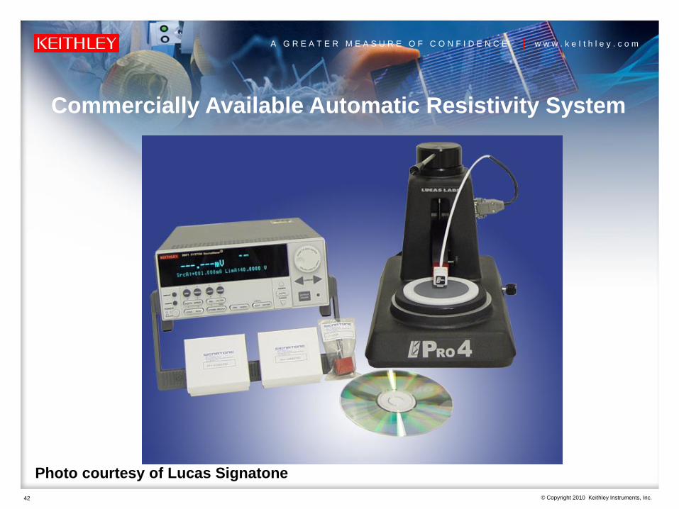
42
Commercially Available Automatic Resistivity System
Photo courtesy of Lucas Signatone

© Copyright 2010 Keithley Instruments, Inc.
A G R E A T E R M E A S U R E O F C O N F I D E N C E | w w w . k e I t h l e y . c o m
43
Issues for High Range Resistances (up to 1E12 ohms)
• Use a 4-point collinear probe that has excellent isolation between
the probes to avoid leakage current errors
• Use a current source with high output impedance (1E14) to avoid
loading errors
• Use a current source with a built-in guard to reduce the effects of
shunt capacitance
• Use voltmeters with high input impedance (1E14 ohms)
• Use shielding to avoid errors due to electrostatic interference
• Use differential electrometer method to avoid issues of common
mode current

© Copyright 2010 Keithley Instruments, Inc.
A G R E A T E R M E A S U R E O F C O N F I D E N C E | w w w . k e I t h l e y . c o m
44
Common Mode Current Errors When Measuring High R
RIN
V
Voltmeter
RV
AC
HI LO
2 3
RC1
1
RC3 RC4
RC
AC
LO
CurrentSource
HI
CommonMode
Current
i
RC2
RS1 RS2 RS3
4
When the resistance of the
sample, RS2, becomes on the
same order of magnitude as
the isolation spec (input LO to
chassis) of the current source
and voltmeter, then common
mode current will flow
affecting the measurement
accuracy.Sample Resistance
Contact
Resistance

© Copyright 2010 Keithley Instruments, Inc.
A G R E A T E R M E A S U R E O F C O N F I D E N C E | w w w . k e I t h l e y . c o m
45
Making Differential Four-Point Probe Measurements
(For Very High Resistances >1Mohm)
V
Voltmeter
21
LOHI
X1Buffer
X1Buffer
HI LO
HI LO HI LO
RC3 RC4RC2RC1
RS1 RS2 RS3
43

© Copyright 2010 Keithley Instruments, Inc.
A G R E A T E R M E A S U R E O F C O N F I D E N C E | w w w . k e I t h l e y . c o m
46
van der Pauw Resistivity Method
V
1
2
3
4
Force
Current
Measure
Voltage
van der Pauw resistivity is a 4-probe
technique that involves applying a current
and measuring a voltage using four small
contacts on a circumference of a flat,
arbitrarily shaped sample.
Test Procedure:
•Force Current (I) on adjacent terminals
•Measure Voltage (V) on an opposite pair of
adjacent terminals
•Repeat measurements around sample
•Calculate resistivity

© Copyright 2010 Keithley Instruments, Inc.
A G R E A T E R M E A S U R E O F C O N F I D E N C E | w w w . k e I t h l e y . c o m
47
van der Pauw Resistivity Method
• vdp configuration is
useful for measuring
very small samples
• Easy to measure Hall
voltage using an
electromagnet to apply
the B field
• Force I and Measure V
on opposite terminals
V
1
2
3
4
Force
Current
Measure
Voltage
Hall Configuration
B

© Copyright 2010 Keithley Instruments, Inc.
A G R E A T E R M E A S U R E O F C O N F I D E N C E | w w w . k e I t h l e y . c o m
48
van der Pauw Resistivity
V7
V8
V1
V2
V4
V5
V6
V3
1 2
34
1 2
34
1 2
34
1 2
34
1 2
34
1 2
34
1 2
34
1 2
34
A series of 8 measurements are performed around the periphery of the sample
to compensate for offsets and are combined mathematically to compute the
resistivity.

© Copyright 2010 Keithley Instruments, Inc.
A G R E A T E R M E A S U R E O F C O N F I D E N C E | w w w . k e I t h l e y . c o m
49
Switching to Perform vdp Measurements
V
1
1
1
2
2
2
3
3
3
4
4
4
Sample
Current
Source
Voltmeter
Switch Matrix
Use a switch matrix to
automatically switch the current
source and voltmeter between all
four terminals of the sample.
Choose a switch system that will
not degrade the measurements.
Use offset compensation
technique – current reversals – to
eliminate voltage offsets due to
the switch.
Use same configuration to
measure the Hall voltage using
an electromagnet.

© Copyright 2010 Keithley Instruments, Inc.
A G R E A T E R M E A S U R E O F C O N F I D E N C E | w w w . k e I t h l e y . c o m
50
High Resistance vdp Measurements
Model 7065 Hall Effect
Card Configuration
Matrix Card that switches
current source and
voltmeter to the 4 terminals
of the sample.
Has unity gain buffers on
the card to avoid problems
with isolation or needing to
use an electrometer to
measure the voltage drops

© Copyright 2010 Keithley Instruments, Inc.
A G R E A T E R M E A S U R E O F C O N F I D E N C E | w w w . k e I t h l e y . c o m
51
Using Four SMUs to Measure High R Samples
SMU2
V Measure
SMU3
V Measure
SMU4
Common
SMU1
I Source
1 2
34
V Difference
i
Model 4200-SCS with 4 SMUs and 4 preamps
– Input impedance >1016
– Accurate low current sourcing, pA
– No leakage errors due to
mechanical switches
– Includes software to automate
measurements and calculate
resistivity
Model 4200-SCS Semiconductor
Characterization System

© Copyright 2010 Keithley Instruments, Inc.
A G R E A T E R M E A S U R E O F C O N F I D E N C E | w w w . k e I t h l e y . c o m
52
Making Good Measurements on High Resistance
Samples
• Use electrostatic shielding to minimize electrical interference– Shield the DUT and all sensitive circuitry
– Use shielded cabling
– Connect the shield to the low terminal of the system
• Use guarding to reduce the effects of leakage current in system– Guarded current source
– Guarded voltmeters
– Use triax cable instead of coax cable
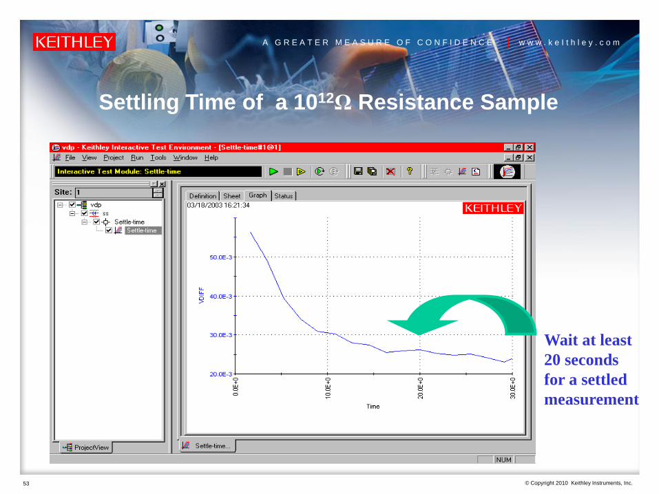
• Allow sufficient settling time– Source I and measure V as a function of time to determine appropriate
settling time
– A diamond sample can take several minutes for settling
© Copyright 2010 Keithley Instruments, Inc.
A G R E A T E R M E A S U R E O F C O N F I D E N C E | w w w . k e I t h l e y . c o m
53
Settling Time of a 1012Ω Resistance Sample
Wait at least
20 seconds
for a settled
measurement

© Copyright 2010 Keithley Instruments, Inc.
A G R E A T E R M E A S U R E O F C O N F I D E N C E | w w w . k e I t h l e y . c o m
54
Summary
Use an appropriate method for measuring the
resistivity. The method will depend on if the material is
a conductor, insulator, or semiconductor.
Choose the appropriate instrumentation.
Apply the proper measurement techniques to avoid
measurement errors.

© Copyright 2010 Keithley Instruments, Inc.
A G R E A T E R M E A S U R E O F C O N F I D E N C E | w w w . k e I t h l e y . c o m
55
Reference Materials
www.keithley.com
Low Level Measurements Handbook, 6th
Edition
Application Notes: Hall effect, van der
Pauw method, four-point collinear probe
method, insulator resistivity, low voltage
measurements, low current
measurements, etc.
White Papers: Delta method, current
reversal techniques, etc.

© Copyright 2010 Keithley Instruments, Inc.
A G R E A T E R M E A S U R E O F C O N F I D E N C E | w w w . k e I t h l e y . c o m
56
Contact Keithley for Further Information
Worldwide Headquarters
Within the USA: 1-888-KEITHLEY
Outside the USA: +1-440-248-0400
Email: [email protected]
Additional offices: www.keithley.com
Europe:
Germany: (+49) 89 849 307 40
Great Britain: (+44) 118 929 7500
Asia:
China: (+86) 10-8447- 5556
Japan: (+81) 3-5733-7555
Korea: (+82) 2-574-7778
Taiwan: (+886) 3-572-9077