technische universität darmstadt fixed-mobile convergence
TRANSCRIPT

Technische Universität Darmstadt
Department of Electrical Engineering and Information TechnologyDepartment of Computer Science (Adjunct Professor)
Multimedia Communications LabProf. Dr.-Ing. Ralf Steinmetz
Fixed-mobile convergence in TISPAN/3GPP IMS.Conception and evaluation of systems for
seamless vertical handover
Diploma Thesis
Submitted by
Christian Esteve Rothenberg
on
8. June 2006
Advisor: Prof. Dr.-Ing. Ralf Steinmetz
Tutor: Dipl.-Inf. Johannes SchmittExternal Tutor: Dr.-Ing. Bangnan Xu (T-Systems Enterprise ServicesGmbH)
KOM-D-246

ii

Ehrenwörtliche Erklärung
Hiermit versichere ich, die vorliegende Diplomarbeit ohne Hilfe Dritter und nur mit den angegebenenQuellen und Hilfsmitteln angefertigt zu haben. Alle Stellen, die aus den Quellen entnommen wurden,sind als solche kenntlich gemacht worden. Diese Arbeit hat in gleicher oder ähnlicher Form noch keinerPrüfungsbehörde vorgelegen.
Darmstadt, den 1. Juni 2006 Christian Esteve Rothenberg
iii

iv

Acknowledgements
Many have contributed during this past months to make this diploma thesis a reality.The order ofappearance of the persons I would like to thank has no special meaning.
I would like to start with my first years at the Escuela Técnica Superior de Telecomunicación of theUniversidad Politécnica de Madrid. The scholarship of the Fundación Angel Barbero helped me fund myfirst years of University, a fact that I will never forget. ProfessorAngel Alvarez showed me the impor-tance of studying abroad and gave me the chance to participate in the exchange program which broughtme to the Technische Universität Darmstadt (TUD). Brigitte Astheimer from theInternational RelationsOffice was of great importance in making my stay in Darmstadt so satisfactory.The International Darm-stadt Exchange Alumni (IDEA) also highly contributed during my integration period into the Germanculture and afterwards as well, allowing me to be part of this team of friends with the common objectiveof amusing the life of every international student coming to Darmstadt.
For giving me the opportunity of doing my diploma thesis at T-Systems EnterpriseServices GmbH,for introducing me to the telecom world and for the supervision of this thesis, Iwould like to expressmy special gratitude to Dr.-Ing. Bangnan Xu. His confidence in me and his contribution in bearingmy research work have been conclusive. For the examination of my diploma thesis, for their valuablecomments and inspiring discussions, I would like to thank all the colleagues from the Mobil & WirelessSolutions (PCT26) Department of T-Systems.
Nothing of this would have been possible without the mentoring of Dipl.-Ing. Johannes Schmittfrom the Multimedia Communications Lab (KOM) of the TUD. Within KOM, headed byProf. Dr.-Ing.Ralf Steinmetz (Adjunct Professor of the Department of Computer Science), I have learned the theoryof communication networks and I have had the chance to contribute in their research activities. I thankProf. Dr.-Ing. Ralf Steinmetz and KOM for these years of formation and for their support while writingmy diploma thesis externally in T-Systems.
In my life, I have encountered many people from whom I have learned important things, both at atechnical and at a personal level. Such persons have been a constant source of motivation. My specialfriends have all had their own important supporting role.
Last but not least, my father José Luis and my mother Annette, for the valuesof life they havetransmitted to me, their love and support, I thank you all.
Darmstadt, 8. June 2006 Christian Esteve Rothenberg
v

vi

Contents
List of Figures viii
List of Tables x
List of Listings xi
List of Abbreviations xiii
1 Introduction 11.1 Motivation . . . . . . . . . . . . . . . . . . . . . . . . . . . . . . . . . . . . . . . . . . 11.2 Scope and methodology . . . . . . . . . . . . . . . . . . . . . . . . . . . . . . . . .. . 21.3 Related work . . . . . . . . . . . . . . . . . . . . . . . . . . . . . . . . . . . . . . . .21.4 Remainder . . . . . . . . . . . . . . . . . . . . . . . . . . . . . . . . . . . . . . . . . .31.5 Terminology . . . . . . . . . . . . . . . . . . . . . . . . . . . . . . . . . . . . . . . . .4
2 The IP Multimedia Subsystem (IMS) 52.1 History and evolution . . . . . . . . . . . . . . . . . . . . . . . . . . . . . . . . . . .. 52.2 Drivers . . . . . . . . . . . . . . . . . . . . . . . . . . . . . . . . . . . . . . . . . .. 52.3 Architecture . . . . . . . . . . . . . . . . . . . . . . . . . . . . . . . . . . . . . . . .. 62.4 SIP used in IMS . . . . . . . . . . . . . . . . . . . . . . . . . . . . . . . . . . . . . .. 9
2.4.1 Basics . . . . . . . . . . . . . . . . . . . . . . . . . . . . . . . . . . . . . . . . 102.4.2 Session Description Protocol . . . . . . . . . . . . . . . . . . . . . . . . . . .. 112.4.3 Extensions for IMS . . . . . . . . . . . . . . . . . . . . . . . . . . . . . . . . . 12
2.5 Operational overview . . . . . . . . . . . . . . . . . . . . . . . . . . . . . . . . .. . . 132.5.1 IMS registration . . . . . . . . . . . . . . . . . . . . . . . . . . . . . . . . . . 132.5.2 IMS session initiation . . . . . . . . . . . . . . . . . . . . . . . . . . . . . . . 17
3 Analysis of IMS based convergence 253.1 Fixed mobile convergence and Next Generation Networks . . . . . . . . .. . . . . . . 25
3.1.1 Motivation for convergence . . . . . . . . . . . . . . . . . . . . . . . . . . .. 263.1.2 Service, device and network convergence . . . . . . . . . . . . . . . .. . . . . 26
3.2 Analysis of IMS on fixed mobile convergence . . . . . . . . . . . . . . . . . .. . . . . 273.2.1 Requirements . . . . . . . . . . . . . . . . . . . . . . . . . . . . . . . . . . . . 273.2.2 Convenience and ease of use . . . . . . . . . . . . . . . . . . . . . . . . . .. . 283.2.3 Service transparency . . . . . . . . . . . . . . . . . . . . . . . . . . . . . . .. 293.2.4 Network convergence . . . . . . . . . . . . . . . . . . . . . . . . . . . . . . .. 313.2.5 Security . . . . . . . . . . . . . . . . . . . . . . . . . . . . . . . . . . . . . . . 333.2.6 Always best connected . . . . . . . . . . . . . . . . . . . . . . . . . . . . . .. 34
3.3 3GPP and TISPAN architectural and functional convergence . . . .. . . . . . . . . . . 373.3.1 3GPP IMS dependencies on access technology . . . . . . . . . . . . . .. . . . 373.3.2 Differences between fixed and mobile access networks . . . . . . . . .. . . . . 39
vii

viii CONTENTS
3.3.3 Requirements for IMS compliant access systems . . . . . . . . . . . . . . . .. 403.3.4 Open issues . . . . . . . . . . . . . . . . . . . . . . . . . . . . . . . . . . . . . 41
3.4 Mobility support on converged networks . . . . . . . . . . . . . . . . . . . .. . . . . . 433.4.1 Mobility concepts . . . . . . . . . . . . . . . . . . . . . . . . . . . . . . . . . 433.4.2 Requirements for mobility in NGN . . . . . . . . . . . . . . . . . . . . . . . . 45
3.5 IMS based mobility management . . . . . . . . . . . . . . . . . . . . . . . . . . . . . .463.5.1 3GPP/3GPP2 approaches on mobility . . . . . . . . . . . . . . . . . . . . . . . 473.5.2 Session continuity support . . . . . . . . . . . . . . . . . . . . . . . . . . . . .483.5.3 Potential solutions for seamless continuity of sessions . . . . . . . . . . . .. . 503.5.4 Challenges towards seamless mobility in NGN . . . . . . . . . . . . . . . . . . 52
3.6 Conclusion . . . . . . . . . . . . . . . . . . . . . . . . . . . . . . . . . . . . . . . . .53
4 Seamless vertical handovers in NGN 554.1 Definitions . . . . . . . . . . . . . . . . . . . . . . . . . . . . . . . . . . . . . . . . . .554.2 Challenges and requirements of seamless vertical handovers . . . . . .. . . . . . . . . 564.3 Mobility management model for NGN . . . . . . . . . . . . . . . . . . . . . . . . . . .58
4.3.1 Monitoring . . . . . . . . . . . . . . . . . . . . . . . . . . . . . . . . . . . . . 604.3.2 Evaluation . . . . . . . . . . . . . . . . . . . . . . . . . . . . . . . . . . . . . 604.3.3 Initiation . . . . . . . . . . . . . . . . . . . . . . . . . . . . . . . . . . . . . . 624.3.4 Decision . . . . . . . . . . . . . . . . . . . . . . . . . . . . . . . . . . . . . . 634.3.5 Execution . . . . . . . . . . . . . . . . . . . . . . . . . . . . . . . . . . . . . . 66
4.4 Mobility Management Function (MMF) . . . . . . . . . . . . . . . . . . . . . . . . .. 704.4.1 Terms and definitions . . . . . . . . . . . . . . . . . . . . . . . . . . . . . . . . 704.4.2 Reference architecture . . . . . . . . . . . . . . . . . . . . . . . . . . . . . .. 714.4.3 Domain based mobility . . . . . . . . . . . . . . . . . . . . . . . . . . . . . . . 754.4.4 Functional overview . . . . . . . . . . . . . . . . . . . . . . . . . . . . . . . . 764.4.5 Vertical handover operations . . . . . . . . . . . . . . . . . . . . . . . . . .. . 844.4.6 SIP based handover mechanisms . . . . . . . . . . . . . . . . . . . . . . . . .. 894.4.7 IP based handover approaches . . . . . . . . . . . . . . . . . . . . . . .. . . . 1004.4.8 Evaluation . . . . . . . . . . . . . . . . . . . . . . . . . . . . . . . . . . . . . 109
4.5 Conclusion . . . . . . . . . . . . . . . . . . . . . . . . . . . . . . . . . . . . . . . . .111
5 Conclusion and future work 113
References 115
List of Figures
2.1 IMS layered architecture. Source [Cum05] . . . . . . . . . . . . . . . . . .. . . . . . . 72.2 SIP trapezoid model shows the separation of signaling and data paths. Source [Bar05] . . 112.3 SIP is an application-layer protocol. SIP messages can carry SDP information and can
be transported over UDP or TCP. . . . . . . . . . . . . . . . . . . . . . . . . . . .. . . 112.4 IMS registration procedures as specified in [NT05c]. . . . . . . . . . .. . . . . . . . . 142.5 Session initiation procedures in a roaming scenario as specified in [NT05c]. . . . . . . . 23
3.1 Relationship between IMS private and public identities, subscription profiles and theimplicit registration set. . . . . . . . . . . . . . . . . . . . . . . . . . . . . . . . . . . . 28
3.2 IMS architecture simplifies the interconnection agreements between telecomproviders.Source Ericsson. . . . . . . . . . . . . . . . . . . . . . . . . . . . . . . . . . . . . .. 30
3.3 IMS architecture allows sharing of network resources independentservice or access type.Source TISPAN. . . . . . . . . . . . . . . . . . . . . . . . . . . . . . . . . . . . . . .. 31
3.4 IMS horizontal integration through replication of common functions. Source Ericsson. . 323.5 High level overview of the network based GSTN interworking breakout process as in
[SA05c]. . . . . . . . . . . . . . . . . . . . . . . . . . . . . . . . . . . . . . . . . . . .333.6 The Go interface requires enhancements at the access network edgepoints. Source [NT05b] 363.7 3GPP and TISPAN access networks acceding IMS Release 7 services. Source [Cum05] . 383.8 Trade-offs in seamless mobility during vertical handovers include AAAC, security and
QoS requirements. . . . . . . . . . . . . . . . . . . . . . . . . . . . . . . . . . . . . . 463.9 In 3GPP packet data network the GTP tunnels the IP traffic towards the user. Source
[Pat04]. . . . . . . . . . . . . . . . . . . . . . . . . . . . . . . . . . . . . . . . . . . . 473.10 3GPP2 network architecture uses Mobile IPv4 to support mobility. Source [Pat04]. . . . 48
4.1 General handover model used in this work identifies required tasks during vertical han-dovers. . . . . . . . . . . . . . . . . . . . . . . . . . . . . . . . . . . . . . . . . . . . .59
4.2 IEEE 802.21 Media Independent Handover function as a shim layer within the mobilitymanagement protocol [Soc05]. . . . . . . . . . . . . . . . . . . . . . . . . . . . .. . . 64
4.3 Optimized SIP based mobility assisted by 802.21 by reducing the disconnection time[DOea]. . . . . . . . . . . . . . . . . . . . . . . . . . . . . . . . . . . . . . . . . . . . 65
4.4 Network controlled CXTP [SLNPK05] flow example initiated by new accessrouter. . . . 694.5 Reference architecture describing the IMS Provider Domain used in thiswork. . . . . . 724.6 User equipment representation. Device with two interfaces, each of them assigned with
a different IP. . . . . . . . . . . . . . . . . . . . . . . . . . . . . . . . . . . . . . . .. 734.7 Reference architecture describing the IMS Provider Domain used in thiswork. . . . . . 764.8 Mapping of MMF functions in the general handover model for NGN. . .. . . . . . . . 774.9 Relationship of IMS and SIP identities, active sessions and IP connected devices. . . . . 784.10 Terminal authentication. . . . . . . . . . . . . . . . . . . . . . . . . . . . . . . . .. . 854.11 MMF mobility approach for vertical handovers using SIP mechanisms. .. . . . . . . . . 90
ix

x LIST OF FIGURES
4.12 Transfer of a session by the MMF through the MRF to perform transcoding between UEswithout common codec. . . . . . . . . . . . . . . . . . . . . . . . . . . . . . . . . . . . 94
4.13 SIP message interception triggers the execution of mobility mechanisms. . . .. . . . . . 954.14 MMF Conference service to achieve seamless mobility during vertical handovers . . . . 984.15 High level procedures for the general approach for user data mobility. . . . . . . . . . . 1014.16 GTP and MIP operate at different layers and offer a comparable tunneling solution to
provide IP mobility. . . . . . . . . . . . . . . . . . . . . . . . . . . . . . . . . . . . . . 1034.17 Integration approach suggesting the reuse of GPRS. Source [Kor, Vodafone] . . . . . . . 1044.18 High level Mobile IPv6 procedures for user data mobility in the case the ANG acts as
the HA. . . . . . . . . . . . . . . . . . . . . . . . . . . . . . . . . . . . . . . . . . . . 1054.19 High level Mobile IPv6 procedures for user data mobility with an Inter-System Mobility
Anchor acting as HA. . . . . . . . . . . . . . . . . . . . . . . . . . . . . . . . . . . . .1064.20 Mobile IP BU bicasting mechanism reduces overall vertical handoverlatency with min-
imum overhead. Source [VPMH]. . . . . . . . . . . . . . . . . . . . . . . . . . . .. . 1074.21 Network based Mobile IPv6 procedures for user data mobility with an Inter-System Mo-
bility Anchor acting as HA. . . . . . . . . . . . . . . . . . . . . . . . . . . . . . . . . . 108

List of Tables
2.1 SIP methods and its description as in RFC 3261 . . . . . . . . . . . . . . . . . . .. . . 102.2 Additional SIP methods used in IMS . . . . . . . . . . . . . . . . . . . . . . . . . .. . 13
3.1 3GPP(R6) and TISPAN R1 and NGN architectural comparison. . . . . .. . . . . . . . 373.2 Pros and cons of mobility solutions at different protocol layers. . . . .. . . . . . . . . . 52
4.1 Context information classification regarding dynamic/static information and user/net-work originated. . . . . . . . . . . . . . . . . . . . . . . . . . . . . . . . . . . . . . . .60
4.2 MMF user subscription related information is stored in the Serving-MMF. .. . . . . . . 804.3 Registered user identities data is entirely centralized in the Serving-MMF . .. . . . . . 804.4 IP connectivity information is distributed in the Proxy and Serving MMF. . .. . . . . . 824.5 Active session description requires storage of information in the P-MMF. . . . . . . . . 844.6 Comparison of GTP, MIPv6 and PMIP based mobility. . . . . . . . . . . . . . .. . . . 1104.7 Evaluation results of SIP vs.IP handover approaches . . . . . . . . . .. . . . . . . . . 111
xi

xii LIST OF TABLES

Listings
2.1 SIP REGISTER request (UE to P-CSCF) . . . . . . . . . . . . . . . . . . . .. . . . . 132.2 SIP REGISTER request inserted headers (P-CSCF to I-CSCF) . . .. . . . . . . . . . . 152.3 401 Unauthorized response (S-CSCF to I-CSCF) . . . . . . . . . . . . .. . . . . . . . 162.4 401 Unauthorized response inserted header (P-CSCF to UE) . . . . .. . . . . . . . . . 162.5 REGISTER request inserted headers with challenge response and IPsec secured (UE to
P-CSCF) . . . . . . . . . . . . . . . . . . . . . . . . . . . . . . . . . . . . . . . . . . . 162.6 200 OK response (S-CSCF to I-CSCF) . . . . . . . . . . . . . . . . . . . . .. . . . . . 172.7 INVITE (UE to P-CSCF) step 1 of the session initiation procedures . . . .. . . . . . . 182.8 INVITE modified headers (S-CSCF to S-CSCF) . . . . . . . . . . . . . . . .. . . . . . 202.9 Storage of information at S-CSCF in the originating network . . . . . . . . . .. . . . . 202.10 Changes in the SDP body of the UPDATE message after resource reservation completed. 212.11 P-Charging-Vector header example. . . . . . . . . . . . . . . . . . . . . .. . . . . . . 214.1 Fuzzy rules define handover initiation triggers . . . . . . . . . . . . . . . . .. . . . . . 624.2 Rule-based decision algorithm where only one access technology canbe activated at a time 654.3 Rule-based decision algorithm where WLAN and GPRS can be simultaneously active . . 654.4 Data representation of context information in XML . . . . . . . . . . . . . . . .. . . . 684.5 SIP NOTIFY message after subscription to the IMS registration state event . . . . . . . 794.6 SIP Contact header including expiration time and priority . . . . . . . . . . . .. . . . . 804.7 SDP description for a session using video over RTP . . . . . . . . . . . . .. . . . . . . 834.8 REGISTER headers proposed for fast IMS registration . . . . . . . .. . . . . . . . . . 874.9 REFER (S-MMF#2 to S-CSCF#2) . . . . . . . . . . . . . . . . . . . . . . . . . .. . . 914.10 Replace header in SIP INVITE for session handover identification .. . . . . . . . . . . 994.11 SIP extensions to handle security considerations . . . . . . . . . . . . . .. . . . . . . . 100
xiii

xiv LISTINGS

List of Abbreviations
2G . . . . . . . . . . . . . . . . . . . . . . . . . . . .3ndGeneration
3G . . . . . . . . . . . . . . . . . . . . . . . . . . . .3rdGeneration
3GPP . . . . . . . . . . . . . . . . . . . . . . . . .3rdGenerationPartnershipProject
3GPP2 . . . . . . . . . . . . . . . . . . . . . . . .3rdGenerationPartnershipProject2
AAA . . . . . . . . . . . . . . . . . . . . . . . . . Authentication,Authorization andAccounting
AAAC . . . . . . . . . . . . . . . . . . . . . . . .AAA and Charging
ABC . . . . . . . . . . . . . . . . . . . . . . . . . .AlwaysBestConnected
AF . . . . . . . . . . . . . . . . . . . . . . . . . . .ApplicationFunction
AIPN . . . . . . . . . . . . . . . . . . . . . . . . .All IP Network
ANG . . . . . . . . . . . . . . . . . . . . . . . . .AccessNetworkGateway
AOR . . . . . . . . . . . . . . . . . . . . . . . . . .Addressof Record
AS . . . . . . . . . . . . . . . . . . . . . . . . . . .AccessSystem
AS . . . . . . . . . . . . . . . . . . . . . . . . . . .ApplicationServer
ASGW . . . . . . . . . . . . . . . . . . . . . . . .AccessSystemGateway
B2BUA . . . . . . . . . . . . . . . . . . . . . . .Back-To-BackUserAgent
BCF . . . . . . . . . . . . . . . . . . . . . . . . . .BorderControlFunction
BG . . . . . . . . . . . . . . . . . . . . . . . . . . .BorderGateway
BS . . . . . . . . . . . . . . . . . . . . . . . . . . . .BearerService
CAPEX . . . . . . . . . . . . . . . . . . . . . . .CapitalExpenditure
CN . . . . . . . . . . . . . . . . . . . . . . . . . . .CorrespondentNode
COPS . . . . . . . . . . . . . . . . . . . . . . . . .CommmonObjectPolicyService
CSCF . . . . . . . . . . . . . . . . . . . . . . . . .Call SessionControlFunction
CSCN . . . . . . . . . . . . . . . . . . . . . . . .Circuit SwitchedCoreNetwork
CT . . . . . . . . . . . . . . . . . . . . . . . . . . .ContextTransfer
CTAA . . . . . . . . . . . . . . . . . . . . . . . . ContextTransferActivateAcknowledgement
CTAR . . . . . . . . . . . . . . . . . . . . . . . .ContextTransferActivateRequest
CTD . . . . . . . . . . . . . . . . . . . . . . . . . .ContextTransferDataReply
CTD . . . . . . . . . . . . . . . . . . . . . . . . . .ContextTransferData
CXTP . . . . . . . . . . . . . . . . . . . . . . . . .Context TransferProtocol
xv

xvi LISTINGS
DHCP . . . . . . . . . . . . . . . . . . . . . . . .DynamicHostConfigurationProtocol
DNS . . . . . . . . . . . . . . . . . . . . . . . . . .DomainNameService
DSL . . . . . . . . . . . . . . . . . . . . . . . . . .Digital SubscriberLine
ETSI . . . . . . . . . . . . . . . . . . . . . . . . . .EuropeanTelecommunicationsStandardsInstitute
FMC . . . . . . . . . . . . . . . . . . . . . . . . . .FixedMobile Convergence
G-MAP . . . . . . . . . . . . . . . . . . . . . . .GlobalMAP
GGSN . . . . . . . . . . . . . . . . . . . . . . . .GatewayGPRSSupportNode
GPRS . . . . . . . . . . . . . . . . . . . . . . . . .GeneralPacketRadioService
GSM . . . . . . . . . . . . . . . . . . . . . . . . .GlobalSystem forMobility
GTP . . . . . . . . . . . . . . . . . . . . . . . . . .GPRSTunnelingProtocol
HA . . . . . . . . . . . . . . . . . . . . . . . . . . .HomeAgent
HLR . . . . . . . . . . . . . . . . . . . . . . . . . .HomeLocationRegister
HO . . . . . . . . . . . . . . . . . . . . . . . . . . .Handover
HSS . . . . . . . . . . . . . . . . . . . . . . . . . .HomeSubscriberServer
I-BCF . . . . . . . . . . . . . . . . . . . . . . . . .Interconnect BCF
I-CSCF . . . . . . . . . . . . . . . . . . . . . . .Interrogating CSCF
IETF . . . . . . . . . . . . . . . . . . . . . . . . . .InternetEngineeringTaskForce
IMS . . . . . . . . . . . . . . . . . . . . . . . . . .IP MultimediaSubsystem
IP . . . . . . . . . . . . . . . . . . . . . . . . . . . .InternetProtocol
IP-CAN . . . . . . . . . . . . . . . . . . . . . . .IP ConnectivityAccessNetwork
IPD . . . . . . . . . . . . . . . . . . . . . . . . . . .IMS ProviderDomain
IPv4 . . . . . . . . . . . . . . . . . . . . . . . . . .InternetProtocolversion4
IPv6 . . . . . . . . . . . . . . . . . . . . . . . . . .InternetProtocolversion6
ISC . . . . . . . . . . . . . . . . . . . . . . . . . . .IMS ServiceControl
ITU . . . . . . . . . . . . . . . . . . . . . . . . . . .InternationalTelecommunicationUnion
IuPS . . . . . . . . . . . . . . . . . . . . . . . . . .Iu PacketSwitched
L-MAP . . . . . . . . . . . . . . . . . . . . . . . LocalMAP
MAP . . . . . . . . . . . . . . . . . . . . . . . . .Mobility AnchorPoint
MGCF . . . . . . . . . . . . . . . . . . . . . . . .MediaGatewayControlFunction
MGCP . . . . . . . . . . . . . . . . . . . . . . . .MediaGatewayControlPart
MGW . . . . . . . . . . . . . . . . . . . . . . . . .MediaGateways
MIH . . . . . . . . . . . . . . . . . . . . . . . . . .MediaIndependentHandover
MM . . . . . . . . . . . . . . . . . . . . . . . . . . Mobility Management
MMF . . . . . . . . . . . . . . . . . . . . . . . . .Mobility ManagementFunction
MN . . . . . . . . . . . . . . . . . . . . . . . . . . .Mobile Node
MRF . . . . . . . . . . . . . . . . . . . . . . . . . .MediaResourceFunction
LISTINGS xvii
MRFC . . . . . . . . . . . . . . . . . . . . . . . . MRFControl
MRFP . . . . . . . . . . . . . . . . . . . . . . . . MRFProcessor
NASS . . . . . . . . . . . . . . . . . . . . . . . . .NetworkAttachmentSubSystem
NGN . . . . . . . . . . . . . . . . . . . . . . . . .NextGenerationNetwork
OMA . . . . . . . . . . . . . . . . . . . . . . . . .OpenMobile Alliance
OPEX . . . . . . . . . . . . . . . . . . . . . . . .OperationsEXpenditures
OSA . . . . . . . . . . . . . . . . . . . . . . . . . .OpenServicesArchitecture
P-CSCF . . . . . . . . . . . . . . . . . . . . . . .Proxy CSCF
P-MMF . . . . . . . . . . . . . . . . . . . . . . .ProxyMMF
PDA . . . . . . . . . . . . . . . . . . . . . . . . . .PersonalDigital Assistant
PDP . . . . . . . . . . . . . . . . . . . . . . . . . .PacketDataProtocol
PDSN . . . . . . . . . . . . . . . . . . . . . . . . .PacketDataGateway
PDSN . . . . . . . . . . . . . . . . . . . . . . . . .PacketDataServingNode
QoS . . . . . . . . . . . . . . . . . . . . . . . . . .Qualityof Service
RACS . . . . . . . . . . . . . . . . . . . . . . . .ResourceAdmissionControlSubsystem
RCEF . . . . . . . . . . . . . . . . . . . . . . . . .ResourceControlEnforcementFunction
RFC . . . . . . . . . . . . . . . . . . . . . . . . . .RequestFor Comments
RNC . . . . . . . . . . . . . . . . . . . . . . . . . .RadioNetworkController
S-CSCF . . . . . . . . . . . . . . . . . . . . . . .ServingCSCF
S-MMF . . . . . . . . . . . . . . . . . . . . . . .ServingMMF
SAE . . . . . . . . . . . . . . . . . . . . . . . . . .SystemArchitectureEvolution
SAP . . . . . . . . . . . . . . . . . . . . . . . . . .ServiceAccessPoint
SBC . . . . . . . . . . . . . . . . . . . . . . . . . .SessionBorderController
SBLP . . . . . . . . . . . . . . . . . . . . . . . . .ServiceBasedLocalPolicy
SCTP . . . . . . . . . . . . . . . . . . . . . . . . .StreamControlTransmissionProtocol
SDP . . . . . . . . . . . . . . . . . . . . . . . . . .SessionDescriptionProtocol
SGSN . . . . . . . . . . . . . . . . . . . . . . . . .ServingGPRSSupportNode
SIP . . . . . . . . . . . . . . . . . . . . . . . . . . .SessionInitiation Protocol
SPT . . . . . . . . . . . . . . . . . . . . . . . . . .ServicePointTriggers
SSO . . . . . . . . . . . . . . . . . . . . . . . . . .SingleSignOn
TCP . . . . . . . . . . . . . . . . . . . . . . . . . .TransmissionControlProtocol
TISPAN . . . . . . . . . . . . . . . . . . . . . . .TelecomsInternet convergedServices &Protocols forAdvancedNetworks
UA . . . . . . . . . . . . . . . . . . . . . . . . . . .UserAgent
UAC . . . . . . . . . . . . . . . . . . . . . . . . . .UserAgentClient
UAS . . . . . . . . . . . . . . . . . . . . . . . . . .UserAgentServer
UDP . . . . . . . . . . . . . . . . . . . . . . . . . .UserDatagramProtocol

xviii LISTINGS
UE . . . . . . . . . . . . . . . . . . . . . . . . . . .UserEquipment
UMA . . . . . . . . . . . . . . . . . . . . . . . . .UnlicensedMobile Access
UMTS . . . . . . . . . . . . . . . . . . . . . . . .UniversalMobile Terrestrial Access
UPE . . . . . . . . . . . . . . . . . . . . . . . . . .UerPlaneEntity
UPE . . . . . . . . . . . . . . . . . . . . . . . . . .UserPlaneEntity
URI . . . . . . . . . . . . . . . . . . . . . . . . . .Uniform ResourceIdentifier
UTRAN . . . . . . . . . . . . . . . . . . . . . . UMTS TerrestrialRadioAccessNetwork
VHE . . . . . . . . . . . . . . . . . . . . . . . . . .Virtual HomeEnvironment
VHO . . . . . . . . . . . . . . . . . . . . . . . . .VerticalHandover
VoIP . . . . . . . . . . . . . . . . . . . . . . . . . .VoiceoverIP
WiMax . . . . . . . . . . . . . . . . . . . . . . . WirelessMetropolitanArea Networks
WLAN . . . . . . . . . . . . . . . . . . . . . . . WirelessLocalAreaNetwork
Chapter 1
Introduction
1.1 Motivation
Great efforts for protocol and architecture standardization are beingmade towards converged IP (InternetProtocol) based telecommunications networks. In the wireless world, the two partnership projects ad-dressing the issue of standard development are the 3rd Generation Partnership Project (3GPP) [3gp06a]and the 3rd Generation Partnership Project 2 (3GPP2) [3gp06b]. From the fixed access side, ETSI (Eu-ropean Telecommunications Standards Institute) TISPAN (Telecoms & Internet converged Services &Protocols for Advanced Networks) [tis06] is also moving towards an all-IPfixed-mobile network archi-tecture named Next Generation Network (NGN).
The emerging of different wireless technologies and the development of avariety of mobile terminalsare evolving to support better user mobility and to deploy new services while maintaining the support oflegacy services. NGNs are envisioned as the seamless integration of different existing wireless and wiredaccess network technologies such as Wireless Local Area Network (WLAN) or Digital Subscriber Line(DSL) and emerging access network technologies like Wireless MetropolitanArea Networks (WiMax).There is a clear need for a converged network architecture that allows true access technology indepen-dence when accessing to services. This is were the promising IP Multimedia Subsection (IMS) definedby 3GPP comes in play.
The IMS is being regarded as the fixed mobile convergence (FMC) enabler. It has been adopted by theinternational standardization groups to be the brain of the NGN. A study of the IMS with regards to thelevel of FMC requirements support is required. In addition to this, the impactsof making access networksIMS compatible need to be understood and required enhancements to provide seamless convergence haveto be identified.
Mobility management over heterogeneous networks is a major requirement for FMC systems. Usersexpect an Always Best Connected (ABC) [GJ03] solution that provides continuous and always best ser-vice through always best available connection anywhere, anytime and anyhow. The actual release ofIMS has to be enhanced with additional functions to support seamless mobility over different access sys-tems. The most challenging issue is the provision of mechanisms to enable seamless vertical handoversbetween heterogenous access networks. How IMS can provide seamless connectivity when changingthe access point to the network is a complex matter of study. When consideringapproaches to handlethis vertical mobility, many questions arise: Traffic anchoring architecture or a distributed one? Net-work based or mobile station based? Network layer based or application level based? Mobile IP (MIP)[SJPA04] or Session Initiation Protocol (SIP)[SRSC+02]? These questions have not a simply yes/noanswer, since each approach has pros and cons. A single solution is probably not enough by itself, a flex-ible efficient combination may be the best fit. Such an adaptive, real and autonomous but still efficientmobility management solution is called for by the next generation fixed mobile converged systems.
1

2 CHAPTER 1. INTRODUCTION
1.2 Scope and methodology
Since IMS is a technology driven by communications providers, the reference architecture is limited tothe domain of a provider. This domain is accessible through different access technologies.
Through a study of the IMS features based on the available technical reports and standards from3GPP, ETSI TISPAN and ITU regarding requirements from FMC systems,the required backgroundto investigate on possible enhancements and new functionalities for the envisioned NGN is provided.Open issues regarding the access using different technologies will be listed and the requirements on theaccess systems will be identified. Mobility management plays a central role in FMC systems, thereforeit is required to understand the difficulties of session continuity during vertical handovers in IMS basednetworks.
A generalized model for handovers in NGN will help to understand the complexity of the processesinvolved during vertical handovers. Only then, will it be possible to fully identify the different issuesand challenges with regards to mobility across different access networksin IMS. Existing solutions willbe surveyed and IMS based concepts and mobility management approaches will be proposed within thedefinition of a Mobility Management Function (MMF).
Much reference work is needed to fully understand the trade-offs of all the involved technologies.The research will be based on the available standards from 3GPP, ETSI, IETF and IEEE and will consideralso the promising work in progress of the IETF through the delivered Internet drafts and the documentsfrom the System Architecture Long Term Evolution (SAE-LTE) working groups from 3GPP. Thus, thereader will note that the work is rich in references and many future work possibilities and alternatives arepointed out. References to related work and specifications, mostly IETF RFCs, that are not so relevantfor the remainder of the work will be placed in footnotes to avoid and overload of the references list.
The reader may already have noticed and should be alerted, that telecom related work is very acronymintensive. In addition to this, terminology is an aspect that is in constant change, due to the dynamism ofthe technology. Terms are subject to different interpretations and a consensus should avoid confusionsto the reader. Therefore, at the end of this chapter general terms and notation convention are introducedand at the beginning of each chapter additional relevant terms are put together. A list of abbreviations isprovided and during the work acronyms may be expanded as required.
The most important background information is the understanding of the IMS architecture and func-tionality. The basics of IMS are introduced in chapter 2 while related concepts and protocols will beintroduced when necessary during the work.
1.3 Related work
The research on IMS is being driven mainly by the industry, less research work on the IMS architecturehas been found in universities. This is justified by the rapid advances in technology and by the difficultiesto set up a real IMS environment in university labs. Nonetheless, the University of Berlin in cooperationwith the Fraunhofer Institute1 are leading the research on IMS in Germany. They successfully deployeda testbed [MWK05] and offer the chance to service developers to test their products on their architecture.
FMC and IMS have become buzzwords used by equipment manufactures tosell their products basedon these new technologies. Many whitepapers [Cum05] are available describing how IMS is becoming aFMC enabler. But, these papers are mainly product marketing oriented andremain at a high level of theIMS architecture when trying to explain the benefits of service, network and device convergence.
Although the concepts of NGN and IMS are relatively new, the terms ofvertical handoverandoverlay networkswere first introduced by [SK98] from the University of Berkeley in 1998. In the Barwanproject [Bea98], they introduced a network architecture for heterogeneous mobile computing.
Since then, significant work has been done on the development of technical solutions to the han-dover of communications across heterogeneous networks. Many techniques and protocols have been
1More information on the open IMS @ FOKUS playground is available athttp://www.fokus.fraunhofer.de/ims/.

1.4. REMAINDER 3
studied and the performance of vertical handovers between many pairs of access technologies have beenevaluated [MYLR04, aSB04, CGZZ04, CP04, DKea05].
[Yla05] is a dissertation on vertical handoff and mobility that proposes a system architecture forvertical handoff in location-aware heterogeneous wireless networks.This work describes very goodthe complexity of vertical handovers. It provides an overview of the keyconcepts in next generationwireless networks and identifies important issues in the emergence of these networks. The scope of thiswork is limited to the vertical handover solution and does not consider telecomoperator requirements.In addition to this, no reference to the IMS architecture is provided in this work.
It can be said that researches on SIP mobility [SW00] are led by A. Dutta and H. Shulzrine2. Appli-cation layer techniques to achieve fast handoff for real-time multimedia trafficin a SIP-based signalingenvironment are presented in [DMC+03]. The authors discuss in [Pro02] issues associated with SIP sig-naling for maintaining continuity of multimedia sessions in a mobile heterogeneous access environment.Advances coming from IEEE have been evaluated in [DOea]. Both authors showed in [Soc05] how anIEEE 802.21 centric approach increases the efficiency of seamless handovers across heterogeneous net-works. IEEE 802.21 works on the convergence of the link layer information of different access networks,currently 3GPP, 3GPP2, WLAN and WiMax.
During the last years, mobility management techniques for Next Generation Networks, also referredto by 4G, have tried to put some light on the challenges and issues coming fromheterogeneous networkconvergence. [AXM04, SHS01, Wan, FHL05, CFS05, Q.204] are very good publications towards asolution to mobility management for next generation wireless systems. Most of the research includes asurvey on available protocols and a large list of requirements for mobility in heterogenous networks.
Although many solutions have been proposed and evaluated to solve inter-system handover chal-lenges, none of these have been studied in an IMS environment. The impactson the IMS, a networkarchitecture still under standardization, can be hardly reproduced in laboratory environments and have tobe first studied analytically with regards to the protocols that govern the IMSengine. Thus, little workto vertical handovers in IMS based systems can be found coming from educational institutions. Relatedwork comes from the industry, where 3GPP SAE LTE [Evo06] have started thinking about the necessaryarchitecture evolution towards a mobility solution for 3GPP and non-3GPP access networks. Up to day,only different approaches have been proposed and analyzed. Final specifications and implementationsare expected in a time frame of 2-3 years.
1.4 Remainder
The remainder of the thesis is organized as follows. This introductory chapter ends with the introductionof general terms and notation used in this work. Chapter 2 introduces the background information withregards to the IP Multimedia Subsystem and related protocols. Chapter 3 surveys the concept of fixed-mobile convergence and its functional requirements at different levels. An analysis of the IMS featuresregarding these convergence introduces more details on IMS functionalityand presents the identifiedopen issues and required further work. Chapter 4 examines the problemof vertical handover in NGN. Amodel for the different steps during a vertical handover in NGN is proposed including a survey on currentresearch directions and available protocols. The chapter suggests a listof requirements on the mobilitymanagement of IMS based networks that will be used for the design of a Mobility Management Function(MMF). A reference architecture and mobility model for an IMS provider domain are described. Finally,the functionality of the proposed MMF is presented and alternative mobility mechanisms are studiedin order to satisfy the requirements of seamless service continuity during vertical handovers. Finally,conclusions are put together and future work is suggested in chapter 5.
2This is not a surprise since H.Schulzrine is the (or one of the) fathers ofSIP. More details about SIP history are providedin chapter 2.4.
4 CHAPTER 1. INTRODUCTION
1.5 Terminology
This part introduces general terms and notations. Further terminology will be presented during the workas needed. In general, RFC 3753 [SMK04] can be used as reference for mobility related terms. Thoughdefinitions and vocabulary coming from 3GPP [SA06b] should be the firstreference when referred to inthe frameworks of 3GPP architectures.
Access System (AS):A collection of entities that provides the user the capability to connect to the IMS[SA05b].
Convergence: Coordinated evolution of formerly discrete networks towards uniformity in support ofservices and applications.
Roaming: Ability to provide service to a user through access from a network different than the networkhe has subscribed to. This defines the visited and the home networks respectively.
Mobile Node (MN): A user equipment (UE) with mobility capabilities. Also referred to as mobileterminal (MT).
Correspondent Node (CN): The communicating partner in a session. Can take the form of another useror machine sharing a communication with the originating node.
User Equipment (UE): A device allowing a user access to network services. The the interface betweenthe UE and the network depends on the access network (e.g. for the purpose of 3GPP specificationis the radio interface).
Notation conventions
In general, the notation used in this work is the same as the one appeared in the3GPP specifications.
User Identities
UE#1’s public user identities are:[email protected], [email protected], etc. UE#1’sprivate user identity is:[email protected]. Similarly, UE#2’s public user identities are:[email protected], [email protected], etc. and UE#2’s private user identity is:[email protected].
Network Entities
UE’s associated entities (only UE#1 is shown, the same principles apply for other user):
• UE#1’s home network is:home1.net
• The P-CSCF serving UE#1 in home1.net is:pcscf1.home1.net
• The S-CSCF serving UE#1 is:scscf1.home1.net
• The I-CSCF in UE#1’s home network (between proxy and serving CSCF)is: icscf1_p.home1.net
Chapter 2
The IP Multimedia Subsystem (IMS)
This chapter presents the basic background information on the IP Multimedia Subsystem (IMS) archi-tecture defined by 3GPP. An overview on the history and evolution of IMS iscomplemented with afunctional and architectural description. Relevant protocols are presented and at the end of the chapterthe two most important IMS operations, namely registration and session initiation,conclude the funda-mentals on IMS.
2.1 History and evolution
3GPP (3rd Generation Partnership Project) drives the specification andstandardization of 3rd generation(3G) mobile. Standards bodies from Europe, USA, Japan, China and South Korea are all involved.After defining the wireless access infrastructure, UMTS Terrestrial Radio Access Network (UTRAN), inRelease 5 (2003), 3GPP introduced the IP Multimedia Subsystem (IMS).
IMS was initially developed as a call control framework for packet-basedservices over 3G mobilenetworks as part of 3GPP, some kind of overlay over GPRS to provide IPservices. It was then extendedto include WLAN roaming and additional services such as presence and instant messaging in Release 6(2004/5).
The key 3GPP Release 6 standards is that the IMS core is defined independent from the accesstechnology, so that any specific requirements for the access should be dealt within the access network(e.g. compression, security). In practice, the IMS’s access independence is still not a reality for fixednetwork access, this is where TISPAN comes in play.
The role of TISPAN (Telecoms & Internet converged Services & Protocols for Advanced Networks)in ETSI is to standardize converged networks using IMS as the core architecture of their NGN. Thismeans adding the ability for fixed network access to interface to IMS and alsorequesting 3GPP toenhance the IMS specification where it has been found to be wireless specific. Discussions within thesegroups are driving the IMS extensions to cover fixed networks in 3GPP Release 7 (work-in-progress).
Recently, broadband providers such as CableLabs [cab06] have started standardization activities toadapt their access networks to the IMS.
2.2 Drivers
Although originally developed for mobile operators, a lot of interest in IMS comes from fixed line oper-ators. Their current fixed-line networks are old and due for replacement and enhancements to competewith new services provided coming from the wireless and Internet world are needed. The current fixedtelephone networks are limited to narrowband voice services and is suffers the risk of being displaced bymobile and Internet telephony services (e.g. VoIP, Skype). An IMS-based network would enable fixedline operators to offer a much wider range of services protecting their precious "walled garden".
5
6 CHAPTER 2. THE IP MULTIMEDIA SUBSYSTEM (IMS)
Despite the widespread industry support for IMS, many uncertainties still remain over its real value.The cost of a providing such a QoS-enabled managed network are veryhigh compared with the Internet’sstateless model. In addition to this, no real IMSkiller services have been defined yet. In order to justifythe capital expenses in IMS, the resulting service must be significantly betterthan that available overthe Internet and people must be willing to pay for it. Whether IMS is a commercialsuccess will bedetermined over the coming years.
The 3GPP2 group adopted the IMS as a base for their Multimedia Domain (MMD)solution thatprovides CDMA2000 based access networks with third generation IP based mobile services. The 3GPP2core definition follows the IMS definition of 3GPP closely but there are slight differences due to thechange of radio technology.
2.3 Architecture
IMS is basically an overlay to the packet-switched domain using Session Initiation Protocol (SIP) to pro-vide multimedia services over IP. IMS decomposes the networking infrastructure into separate functionswith standardized interfaces between them. Each interface is specified as areference point. A referencepoint is a conceptual point at the conjunction of two non-overlapping functional entities that can be usedto identify the type of information passing between these functional entities. A reference point may ormay not correspond to one or more physical interfaces between pieces of equipment.
The standards do not mandate which functions should be co-located, as this depends on the scale ofthe application, and a single device may contain several functions. The architecture of IMS is based ona collection of logical functions that can be divided into three layers (eachof which is described by anumber of equivalent names), as shown in figure 2.1.
User or Transport Plane: The transport and endpoint layer initiates and terminates signaling to setupsessions and provides bearer services between the endpoints. Media gateways are provided toconvert from/to analog/digital voice telephony formats to/from IP packets using the Real TimeProtocol (RTP)
Control or Signaling Plane: IMS signaling is based on SIP on top of IPv6. The session control layercontains the call control functions that enable endpoints to be registered with the network andcalls to be setup between them. It also contains the functions that control the media gateways andservers so as to provide the requested services.
Service or Application Plane: Finally, the application server layer allows services to be built based onthe bearer services and the call control services of the other two layers. Besides supporting legacyservices, it can be used to provide novel non-telephony services. The separation from the sessioncontrol layer allows heterogeneous sessions to be setup based on the SIP interface.
The separation from the transport and endpoint layer allows multiple bearer services to be combinedin a single call. This distributed architecture provides an extremely flexible andscalable solution. Figure2.1 shows the access networks supported in Releases 5,6 and 7. Details onthe entities within the accesssystems are not relevant at this point and are later introduced in chapter 3.3. Note that IMS functionalityis in its essence independent from the access technology.The collection of network entities and interfaces that provides the underlying IP transport connectivitybetween the UE and the IMS entities is referred as IP-Connectivity AccessNetwork (IP-CAN) [SA05c].IP-CAN and the termaccess systemrefer to the same network concept and are used indistinctly in thiswork. An example of an IP-CAN or an access system is GPRS.

2.3. ARCHITECTURE 7
Figure 2.1: IMS layered architecture. Source [Cum05]
Functional elements
The IMS architecture defines the logical elements necessary to implement next-generation multimediaservices across multiple network types. It is important to note that these logical functions do not neces-sarily have an one-to-one relationship with physical equipment. The components of the IMS architecturerefer to functions, not platforms. Multiple functions can be mapped to a singlenetwork device, and,conversely, a single function can conceivably be implemented across multiplephysical platforms. Thefollowing are descriptions of functions and concepts of IMS [KMT05, PMKN04, Cum05]:
Call Session Control Function (CSCF)The CSCFs provide session control for the IMS. They coor-dinate with other network elements to control session features, routing, and resource allocation.There are three different types of CSCFs in the IMS architecture:
• Serving CSCF (S-CSCF)the main home network session control point for the user fororiginating or terminating sessions.
• Proxy CSCF (P-CSCF)is the contact point into the IMS from the user.
• Interrogating CSCF (I-CSCF) the inter IMS contact point (eg. between home and visitednetworks).
The S-CSCFacts basically as a registrar, as defined in IETF RFC 3261 [SRSC+02]. In this roleit accepts SIP REGISTER requests and creates a binding between the public user ID and the terminallocation. The S-CSCF retrieves the subscriber profile from the Home Subscriber Server (HSS), includingfilter criteria that indicate the ASs providing service control for this user. To support service control, theS-CSCF interacts with these ASs during SIP signaling. During session establishment or modification,

8 CHAPTER 2. THE IP MULTIMEDIA SUBSYSTEM (IMS)
the S-CSCF monitors the Session Description Protocol (SDP) to ensure thatthe session is within theboundaries of the subscriber’s profile.
The S-CSCF uses the filter criteria to involve application servers as neededin order to provide theservices and features to which the user subscribes. It forwards SIPmessages to each AS in the orderindicted by the filter criteria. After the last AS is contacted, the SIP message is then sent toward theintended destination. The filter criteria can be set on various service trigger points, including any knownSIP method (e.g. REGISTER, INVITE), the presence or absence of any header, the content of any header,the direction of the request with respect to the served user, and SDP.
The S-CSCF also performs routing of SIP messages on behalf of the originating UE. It obtains theaddress of an I-CSCF (or other IP endpoint) for the network operatorserving the destination subscriberfrom a domain name server (DNS) by using the destination name of the terminatingsubscriber; it thenforwards the SIP request toward the destination. If the destination name ofthe terminating subscriberis determined to be a PSTN address, the S-CSCF forwards the request to aBGCF for routing towardthe PSTN. On behalf of the destination endpoint, the S-CSCF forwards the SIP request to a P-CSCFaccording to the subscriber’s registered location, or, for an unregistered subscriber, it may send or redirectthe SIP request to an alternate endpoint according to call forwarding ora similar service.
The I-CSCF serves as the initial point of contact to the IMS home network from other networks. Itperforms a stateless SIP proxy function. It routes received SIP requests to the S-CSCF assigned to theuser or selects an S-CSCF if one is not currently assigned. The I-CSCFassigns S-CSCFs upon initial UEregistration and when terminating services for unregistered users. The I-CSCF is responsible for IMSinterworking, providing means for network topology hiding and security functionalities. An InterconnectBorder Control Function (I-BCF) offers additional interworking functions such as IPv4-IPv6 translationsor firewall functions.
The P-CSCF serves as the initial point of contact for a user terminal to the IMS. It performs astateful SIP proxy function, sending SIP REGISTER requests from theUE to an I-CSCF in the homenetwork, which is determined using the home domain name provided by the UE. The P-SCCF sends allsubsequent SIP messages received from the UE to the S-CSCF whose name it has received as a result ofthe registration procedure. The P-CSCF also ensures that a valid public user identity for the IMS user isinserted into UE-initiated SIP requests. It performs SIP message compression to reduce the amount ofdata sent to or from the UE. It supports resource and admission controlcapabilities by interacting withthe transport layer for networks where this approach is employed.
Application Server (AS): Host applications that support the delivery of services. For example, providerscan deploy application servers to support services such as messaging or presence management. TheAS is connected to the Serving CSCF via the IMS Service Control (ISC) interface. The AS offer-ing value added IP multimedia services resides either in the user’s home network or in a third partylocation. The third party could be another network or simply a stand-alone AS. AS acts as useragents, proxy server, 3rd party call control [SRPSC04] or a Back-To-Back User Agent (B2BUA)[SRSC+02].
Home Subscriber Server (HSS):Manages information about subscribers and their current location.The profile and the preferences of each user are stored in this database. By centralizing this in-formation, service providers can simplify administration and ensure a consistent view of activesubscribers across all services. It supports IMS-level authentication and authorization and holdsthe IMS subscriber profiles. The HSS also stores the currently assignedS-CSCF. A home networkmay contain one or several HSSs. The number of HSSs depends on the number of subscribers, thecapacity of the equipment, and the organization of the network. A SubscriberLocation Function(SLF) is then used as the HSS front-end to provide the information about theHSS containing theinformation of a requested user.
Media Resources Function (MRF): Media resources stream basic media content to IP endpoints, allowcontrol of those streams, and enables jitter buffering, control error rates, etc. for all IP-based

2.4. SIP USED IN IMS 9
services. Injecting tones, announcements, or other multimedia content into calls or sessions isenabled by the media resource function control (MRFC) and media resource function processor(MRFP). While the MRFC provides the intelligence, the MRFP provides the heavy processingrequired for multimedia services.
Media Gateway Control Functions: The gateway control functions manage media gateways (MGW)and handle the communications between the IP and SS7 networks to enable interworking with thePSTN. The breakout gateway control function (BGCF) selects the network in which the connectionto the PSTN is to occur for a given session. If the BGCF determines that the breakout is to occurin the same network in which the BGCF is located, then the BGCF will select a media gatewaycontrol function (MGCF) element, which will be responsible for the interworking with the PSTNfor signaling, (usually selecting the adequate signaling gateway (SGW). The transcoding of theuser data is done at the MGW.
2.4 SIP used in IMS
The key technology behind IMS is the Session Initiation Protocol (SIP) [SRSC+02]. Back to 1996,H.Schulzrinne’s Internet draft of SIP was originally intended to create amechanism for inviting peo-ple to large scale multipoint conferences on the Internet Multicast Backbone (Mbone). The first draftwas known as "draft-ietf-mmusic-sip-00"1. The standardization progress continued adding new requestand functionalities and in March 1999 SIP RFC 2543 was published. Later,it was modified further togenerate the actual version of RFC 3261 [SRSC+02].
As described in the standard:SIP is an application-layer control (signaling) protocol for creating,modifying and terminating sessions with one or more participants. 3GPP has chosen SIP as the signalingprotocol in many of the important interfaces between elements in of the IMS. SIP performs multi mediasession services including:
1. create, modify and release multi media calls
2. allow new party to join in an ongoing multi media call
3. user location management
4. user availability management
5. management of user’s capability set for call set-up
6. session negotiation
7. transparent mapping of user’s name and services
8. security service by using challenge-response mechanism
9. encryption and privacy services
Carriers and service providers have been using SIP to build new products for sometime. There areseveral big advantages to building a new feature or service using SIP:
Simple: It is based on a request-response interaction model, very simple and comprehensive for develop-ers. Messages are text-based which makes them easy to parse, create,read, understand and debug.Thanks to its simplicity, SIP is very scalable, extensible, and adaptable to different architecturesand deployment scenarios.
Extensible: Sessions can be set up for any media type, be it voice, video, application sharing or upcom-ing session types. Extensions can be easily defined (see chapter 2.4.3).
1mmusic is an acronym for Multiparty Multimedia Session Control, nothing to do with music or voice applications. In thosedays, IP telephony did not really exist.
10 CHAPTER 2. THE IP MULTIMEDIA SUBSYSTEM (IMS)
Flexible: Easy interaction with the individual protocol messages (within limits) is allowed. Develop-ment based on SIP becomes much easier and allows the interaction with many protocols (seechapter 2.4.2).
2.4.1 Basics
The two basic components within SIP are the SIP user agent (UA) and the SIP network server . The useragent is the end system component for the session and the SIP server is the network entity handling thesession signaling.
The user agent itself has a client element, the User Agent Client (UAC) anda server element, theUser Agent Server (UAS) . The client element initiates session by sendingSIP requests and the serverelement answers by sending SIP responses. So, peer-to-peer calls follow a client-server protocol model.
The main functions of the SIP servers is to provide name resolution and userlocation (Registrarfunctionality). A caller is unlikely to know the current IP address or host name of the called partner.SIP servers provide means to locate users and pass the messages to otherservers using next hop routingprotocols.
SIP borrows the addressing system from the E-mail model (SMTP). Eachuser is identified througha hierarchical URL that is built around elements such as a user’s phone number or host name (e.g.sip:[email protected]). By using DNS the requests to are delivered theserver that can appro-priately handle them.
SIP servers can operate in two different modes: stateful and stateless .A stateful mode stores theincoming requests it receives, along with the responses it sends back and the outgoing requests it sendson. In a stateless mode no information is stored once it the request is sent. Stateless servers are likelyto be in the backbone of the network architecture (usually Proxy Servers) and stateful-mode servers arelikely to be the brain of the network controlling domains of users. In IMS, all the CSCF are statefulservers since their operations are not limited to just receive and pass messages.
SIP Methods
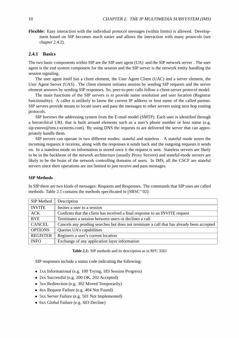
In SIP there are two kinds of messages: Requests and Responses. Thecommands that SIP uses are calledmethods. Table 2.1 contains the methods specificated in [SRSC+02]:
SIP Method Description
INVITE Invites a user to a sessionACK Confirms that the client has received a final response to an INVITE requestBYE Terminates a session between users or declines a callCANCEL Cancels any pending searches but does not terminate a call that has already been acceptedOPTIONS Queries UA’s capabilitiesREGISTER Registers a user’s current locationINFO Exchange of any application layer information
Table 2.1: SIP methods and its description as in RFC 3261
SIP responses include a status code indicating the following:
• 1xx Informational (e.g. 100 Trying, 183 Session Progress)
• 2xx Successful (e.g. 200 OK, 202 Accepted)
• 3xx Redirection (e.g. 302 Moved Temporarily)
• 4xx Request Failure (e.g. 404 Not Found)
• 5xx Server Failure (e.g. 501 Not Implemented)
• 6xx Global Failure (e.g. 603 Decline)

2.4. SIP USED IN IMS 11
A SIP message includes a start line (one line), headers (one or more lines)and a body (optional). SIPuses MIME, the de facto standard for describing content on the Internet, to convey information aboutthe protocol used to describe the session. As a result, SIP messages cancontain almost everything (e.g.images, audio files, authorization tokens, billing data, etc.). Examples of SIP messages and SIP signalingflows for registration and session initiation are later presented in chapter 2.5.
One important feature of SIP based communications is the separation of the signaling (control) anddata (transport) paths. While SIP messages between communicating peers (UAC and UAS) usually passthrough intermediate proxies, the data path goes directly from one end-point to the other. This model istypically referred as the "SIP trapezoid" (see figure 2.2).
The main advantages of this model for telecom operators is that it allows full control over the sessionsignaling and offers at the same time efficient end to end user data exchange.
Figure 2.2: SIP trapezoid model shows the separation of signaling and data paths. Source [Bar05]
2.4.2 Session Description Protocol
SIP is used in conjunction with other protocols (DNS, RTP, Diameter, SDP, etc.) in order to providecomplete services to the users. However, the basic functionality and operation of SIP does not dependon any of these protocols. Figure 2.3 shows the sit of SIP in the protocol stack and its interworking withother protocols.
Figure 2.3: SIP is an application-layer protocol. SIP messages can carry SDP information and can be transportedover UDP or TCP.
The most relevant protocol used with SIP may be the Session Description Protocol (SDP) [SHJ98].As per RFC 2327:SDP is intended for describing multimedia sessions for the purposes of session an-nouncement, session invitation, and other forms of multimedia session initiation.

12 CHAPTER 2. THE IP MULTIMEDIA SUBSYSTEM (IMS)
SDP provides means for capabilities negotiation as specified in RFC 3264 [SRS02a]. Users involvedin a call can agree on the features supported while recognizing that not all the parties can support thesame level of features. The negotiation is based in an offer-answer model. SDP includes:
• Type of media (video, audio, etc.)
• Transport protocol (RTP/UDP/IP, H.320, etc.)
• Format and codecs of the media (H.261 video, MPEG video, etc.)
• Contact information to receive thee media (addresses, ports, formats, etc.)
Further relevant protocols in IMS will be during the work introduced and include COPS [SDBC+00]for QoS management and Diameter [SCLG+03] for AAA functionalities.
2.4.3 Extensions for IMS
SIP itself does not provide services. Rather, SIP provides primitives that can be used to implementdifferent services in conjunction with other protocols. Although SIP is a protocol that fulfills most ofthe requirements for establishing a session in an IP network, for its use in a telecom architecture, SIPrequired some additional extensions to provide the same services as currently supported in wired (e.g.PSTN) or wireless communications (e.g. GSM).
The requirements identified by 3GPP to support SIP for Release 5 of the 3GPP IMS in cellularnetworks are expressed in RFC 4083. The list of requirements is large and includes issues related to:
• Interaction with QoS resource allocation
• SIP compression
• Routing of SIP messages
• Identification of users
• Charging
• Access domain security
The response to these requirements appeared in RFC 3455 (now updatedin [SDra05]). Private header(P-Header) extensions have been defined to address those requirements:
• P-Asserted-Identity: Allows the network (e.g. P-CSCF) to assert a public user identity for iden-tifying the calling user.
• P-Called-Party-ID: Allows the terminating UE to learn dialed public user identity that triggeredthe call.
• P-Access-Network-Info:Allows the UE to provide information related to the access network it isusing (e.g. cell ID).
• P-Visited-Network-ID: Allows the home network to discover, via registration, the identities ofthe networks utilized by the user.
• P-Associated-URI:Allows the home network (e.g. S-CSCF) to return a set of URIs associatedwith the public user identity under registration.
• P-Charging-Function-Addresses:Allows for distributing addresses of charging function entities.
• P-Charging-Vector: Allows for sharing of charging correlation information. Used to include IPconnectivity network charging information at the P-CSCF in the visited network.
In addition to the P-Headers, the SIP methods described in table 2.2 are usedin the IMS to leverageSIP to be used for telecom services.
2.5. OPERATIONAL OVERVIEW 13
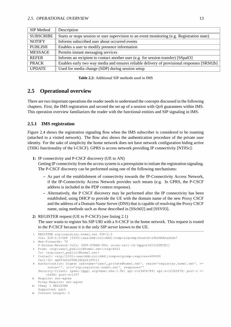
SIP Method Description
SUBSCRIBE Starts or stops session or user supervision to an event monitoring (e.g. Registration state)NOTIFY Informs subscribed user about occurred eventsPUBLISH Enables a user to modify presence informationMESSAGE Permits instant messaging servicesREFER Informs an recipient to contact another user (e.g. for session transfer) [SSpa03]PRACK Enables early two way media and ensures reliable delivery of provisionalresponses [SRS02b]UPDATE Used for media change (SDP) during session setup
Table 2.2: Additional SIP methods used in IMS
2.5 Operational overview
There are two important operations the reader needs to understand the concepts discussed in the followingchapters. First, the IMS registration and second the set up of a session with QoS guarantees within IMS.This operation overview familiarizes the reader with the functional entities andSIP signaling in IMS.
2.5.1 IMS registration
Figure 2.4 shows the registration signaling flow when the IMS subscriber is considered to be roaming(attached to a visited network). The flow also shows the authentication procedure of the private useridentity. For the sake of simplicity the home network does not have network configuration hiding active(THIG functionality of the I-CSCF). GPRS is access network providing IPconnectivity [NT05c]:
1: IP connectivity and P-CSCF discovery (UE to AN)Getting IP connectivity from the access system is a prerequisite to initiate the registration signaling.The P-CSCF discovery can be performed using one of the following mechanisms:
– As part of the establishment of connectivity towards the IP-Connectivity Access Network,if the IP-Connectivity Access Network provides such means (e.g. In GPRS, the P-CSCFaddress is included in the PDP context response).
– Alternatively, the P CSCF discovery may be performed after the IP connectivity has beenestablished, using DHCP to provide the UE with the domain name of the new ProxyCSCFand the address of a Domain Name Server (DNS) that is capable of resolving the Proxy CSCFname, using methods such as those described in [SSch02] and [SSV03].
2: REGISTER request (UE to P-CSCF) (see listing 2.1)The user wants to register his SIP URI with a S-CSCF in the home network. Thisrequest is routedto the P-CSCF because it is the only SIP server known to the UE.
1 REGISTER sip:registrar.home1.net SIP/2.0Via: SIP/2.0/UDP [5555::aaa:bbb:ccc:ddd];comp=sigcomp;branch=z9hG4bKnashds7
3 Max-Forwards: 70P-Access-Network-Info: 3GPP-UTRAN-TDD; utran-cell-id-3gpp=234151D0FCE11
5 From: <sip:[email protected]>;tag=4fa3To: <sip:[email protected]>
7 Contact: <sip:[5555::aaa:bbb:ccc:ddd];comp=sigcomp>;expires=600000Call-ID: apb03a0s09dkjdfglkj49111
9 Authorization: Digest username="[email protected]", realm="registrar.home1.net", ←֓nonce="", uri="sip:registrar.home1.net", response=""
Security-Client: ipsec-3gpp; alg=hmac-sha-1-96; spi-c=23456789; spi-s=12345678; port-c ←֓=2468; port-s=1357
11 Require: sec-agreeProxy-Require: sec-agree
13 CSeq: 1 REGISTERSupported: path
15 Content-Length: 0

14 CHAPTER 2. THE IP MULTIMEDIA SUBSYSTEM (IMS)
P- CSCF HSS UE I - CSCF S- CSCF
2. REGISTER
8. 401 Unauthorized
1. IP connectivity & P- CSCF discovery
DNS
Visited network ( visited1.net ) Home Network ( home1.net )
4. REGISTER
3. DNS Q - R
7. Authentication
5. User Registration Q - R
6. REGISTER
9. 401 Unauthorized 10. 401 Unauthorized
11. REGISTER
18. 200 OK
13. REGISTER
12. DNS Q - R
14. User Registration Q - R
15. REGISTER
19. 200 OK 20. 200 OK
17. Registration
16. Authentication
Figure 2.4: IMS registration procedures as specified in [NT05c].
Listing 2.1: SIP REGISTER request (UE to P-CSCF)
Request-URI: The Request-URI (the URI in the first line that follows the method name, "REG-ISTER", in the first line) indicates the destination domain of this REGISTER request. Thisinformation is stored in the USIM. The rules for routing a SIP request describe how to useDNS to resolve this domain name ("registrar.home1.net") into an address or entry point intothe home operator’s network (the I-CSCF).
Via: IPv6 address of the UE allocated during the PDP Context Activation process.
Max-Forwards: Set to 70 by the UE and used to prevent loops.
P-Access-Network-Info: the UE provides the access-type and access-info, related to the servingaccess network.
From: This indicates the public user identity originating the REGISTER request. The public useridentity may be obtained from the USIM.
To: This indicates the public user identity being registered. This is the identity by which otherparties know this subscriber. It may be obtained from the USIM.

2.5. OPERATIONAL OVERVIEW 15
Contact: This indicates the point-of-presence for the subscriber - the IP address of the UE. Thisis the temporary point of contact for the subscriber that is being registered. Subsequentrequests destined for this subscriber will be sent to this address. This information is stored inthe S-CSCF.
Authorization: It carries authentication information. The private user identity ([email protected])is carried in the user name field of the Digest AKA protocol. The uri parameter (directive)contains the same value as the Request-URI. The realm parameter (directive) contains thenetwork name where the username is authenticated.
Security-Client: Lists the supported algorithm(s) by the UE.
Supported: This header is included to indicate to the recipient that the UE supports the Pathheader. Upon receiving this request the P-CSCF will set it’s SIP registration timer for thisUE to the Expires time in this request.
3: DNS Query-Response (P-CSCF - DNS server)Based on the user’s URI, the P-CSCF determines that UE is registering from a visiting domain andperforms the DNS queries (on the register domain in theRequest-URI) to locate the I-CSCF in thehome network.
4: REGISTER request (P-CSCF to I-CSCF)The P-CSCF does following actions:
– Adds itself to thePathheader value to stay in the SIP signaling path.
– Adds also theP-Visited-Network-IDheader with the contents of the identifier of the P-CSCFnetwork.
– Adds theP-Charging-Vectorheader and populates the IMS charging identifiericid parame-ters with a globally unique value.
– Removes theSecurity-Clientheader and associated "sec-agree" option-tags.
– Removes theProxy-Requireheader as it is empty now.
– Forwards the REGISTER request from the P-CSCF to the I-CSCF in the home domain.
The changes in the SIP REGISTER message are shown in listing 2.2.
1
Path: <sip:[email protected];lr>3 Require: path
P-Visited-Network-ID: "Visited Network Number 1"5 P-Charging-Vector: icid-value="AyretyU0dm+6O2IrT5tAFrbHLso=023551024"
Listing 2.2: SIP REGISTER request inserted headers (P-CSCF to I-CSCF)
5: User Registration Query-Response (I-CSCF with HSS)Cx procedure using the Diameter protocol [SCLG+03] to request information related to the regis-tration status of the subscriber by sending the private user identity, public user identity and visiteddomain name to the HSS. The HSS returns the S-CSCF required capabilities andthe I-CSCF usesthis information to select a suitable S-CSCF.
6: REGISTER request (I-CSCF to S-CSCF)REGISTER request is forwarded from the I-CSCF to the selected S-CSCF.
7: Cx: Authentication procedure (S-CSCF with HSS)2
As the REGISTER request arrived without integrity protection to the P-CSCF, the S-CSCF shallchallenge it. For this, the S-CSCF requires at least one authentication vector (AV)3 (available in
2For detailed description of the Cx procedure see 3GPP TS 29.2283For detailed description of the authentication vector, see 3GPP TS 33.203.

16 CHAPTER 2. THE IP MULTIMEDIA SUBSYSTEM (IMS)
the HSS) to be used in the challenge to the user. The HSS stores the informationabout the S-CSCFassigned to serve this user.
8: 401 Unauthorized response (S-CSCF to I-CSCF)The authentication challenge is constructed with the AV and is sent towards theUE in theWWW-Authenticatefield of the 401 Unauthorized response (see listing 2.3).
2 SIP/2.0 401 UnauthorizedVia: SIP/2.0/UDP icscf1_p.home1.net;branch=z9hG4bK351g45.1, SIP/2.0/UDP pcscf1. ←֓
visited1.net;branch=z9hG4bK240f34.1, SIP/2.0/UDP [5555::aaa:bbb:ccc:ddd];comp= ←֓sigcomp;branch=z9hG4bKnashds7
4 From: <sip:[email protected]>;tag=4fa3To: <sip:[email protected]>; tag=5ef4
6 Call-ID: apb03a0s09dkjdfglkj49111WWW-Authenticate: Digest realm="registrar.home1.net", nonce=base64(RAND + AUTN + ←֓
server specific data), algorithm=AKAv1-MD5, ik="00112233445566778899aabbccddeeff", ←֓ck="ffeeddccbbaa11223344556677889900"
8 CSeq: 1 REGISTERContent-Length: 0
Listing 2.3: 401 Unauthorized response (S-CSCF to I-CSCF)
WWW-Authenticate: The S-CSCF challenges the user including a nonce value the quoted stringencoded in base64 and formed by the concatenation of the AV parameters (in this case IMSAKA 4 was used: RAND, AUTN and server specific data). The S-CSCF appends also theIntegrity Key (IK) and the Cyphering key (CK) for integrity protection. The base64 encodedvalue may look like:nonce="A34Cm+Fva37UYWpGNB34JP".
9-10: Unauthorized response (I-CSCF to P-CSCF and P-CSCF to UE)The 401 Unauthorized response is forwarded to the user first by the I-CSCF and finally by theP-CSCF.In order to complete a secure path with the UE, the P-CSCF offers the preferred security algorithmsand parameters in aSecurity-Serverfield (see listing 2.4). The lower the q value, the higher priorityhas the protocol. In this case, 0.1 means IPsec5 is the first preferred choice.
Security-Server: ipsec-3gpp; q=0.1; alg=hmac-sha-1-96; spi-c=98765432; spi-s=87654321; ←֓port-c=8642; port-s=7531
Listing 2.4: 401 Unauthorized response inserted header (P-CSCF to UE)
11: REGISTER request (UE to P-CSCF)
The REGISTER message equals the request in step 2 but this time it carries theresponse to theauthentication challenge received in the 401 Unauthorized response. The message is protected bythe IPsec security agreement (SA) negotiated as represented in theSecurity-Verifyfield (see listing2.5).
1 Authorization: Digest username="[email protected]", realm="registrar.home1.net", ←֓nonce=base64(RAND + AUTN + server specific data), algorithm=AKAv1-MD5, uri=" ←֓
sip:registrar.home1.net", response="6629fae49393a05397450978507c4ef1"Security-Client: ipsec-3gpp; alg=hmac-sha-1-96; spi-c=23456789; spi-s=12345678; port-c ←֓
=2468; port-s=13573 Security-Verify: ipsec-3gpp; q=0.1; alg=hmac-sha-1-96; spi-c=98765432; spi-s=87654321; ←֓
port-c=8642; port-s=7531
Listing 2.5: REGISTER request inserted headers with challenge responseand IPsec secured (UE to P-CSCF)
4Refer to RFC 3310 for the AKA specifications and 3GPP TS 33.203 for details on AKA used in IMS.5IPsec security protocols are specified in RFC 2401.

2.5. OPERATIONAL OVERVIEW 17
12: DNS Query-Response (P-CSCF - DNS server)Same procedures as in step 3.
13: REGISTER request (P-CSCF to I-CSCF)Same procedures as in step 4.
14: User Registration Query-Response (I-CSCF with HSS)The difference to step 5 is that the HSS returns the S-CSCF name which was previously selectedin step 5 (Cx: User registration status query procedure).
15: REGISTER request (I-CSCF to S-CSCF)Same procedures as in step 6.
16: Authentication (S-CSCF)Upon receiving an integrity protected REGISTER request carrying the authentication challengeresponse, the S-CSCF checks that the expected response matches the received challenge response.
17: Registration(S-CSCF with HSS)If successfully authenticated, then the public user identity is registered in theS-CSCF. The S-CSCF informs the HSS that the user has been registered via a Diameter Cx S-CSCF registrationnotification procedure. The HSS includes the user profile in the responsesent to the S-CSCF.The user profile includes all the relevant information of the user subscription to the IMS such asregistered services, charging information, initial filter criteria, etc.
18: 200 OK response (S-CSCF to I-CSCF) (see listing 2.6)The S-CSCF sends a 200 OK response indicating the successful of the registration. The S-CSCFinserts two headers:
– A Service-Routeheader including its own URI and a character string in the user part todifferentiate the direction of the requests (mobile originating or terminating)6.
– A P-Associated-URIheader includes other public URIs belonging to the registration set ofthe user that have been implicitly registered (see chapter 3.2.2 for more detailsof the implicitregistration procedure).
1 SIP/2.0 200 OKVia: SIP/2.0/UDP icscf1_p.home1.net;branch=z9hG4bK351g45.1, SIP/2.0/UDP pcscf1. ←֓
visited1.net;branch=z9hG4bK240f34.1, SIP/2.0/UDP [5555::aaa:bbb:ccc:ddd]:1357;comp ←֓=sigcomp;branch=z9hG4bKnashds7
3 Path: <sip:[email protected];lr>Service-Route: <sip:[email protected];lr>
5 From:To:
7 Call-ID:Contact: <sip:[5555::aaa:bbb:ccc:ddd]:1357;comp=sigcomp>;expires=600000
9 CSeq:Date: Wed, 15 April 2006 00:47:19 GMT
11 P-Associated-URI: <sip:[email protected]>, <sip:[email protected]>, <sip: ←֓[email protected];user=phone>
Content-Length:
Listing 2.6: 200 OK response (S-CSCF to I-CSCF)
19-20: 200 OK response (I-CSCF to P-CSCF and P-CSCF to UE)The 200 OK response is forwarded towards the UE. The P-CSCF savesthe value of theService-Routeheader and associates it with the UE for routing of future service requests.
2.5.2 IMS session initiation
In this subsection principles and signaling flows for establishing sessions as specified in [NT05c] arepresented. For the sake of simplicity, the following assumptions as shown in figure 2.5 apply:
6RFC 3680 describes a Service Route extension header to provide a mechanism by which a registrar may inform a registeringuser agent (UA) of a service route that the UA may use to request outbound services from the registrar’s domain

18 CHAPTER 2. THE IP MULTIMEDIA SUBSYSTEM (IMS)
• Mobile origination. The terminating signaling in the destination network is not shown.
• UE is located in a visited network (roaming scenario). In a non-roaming scenario the signalingflow would be the same but the P-CSCF would be located in the home network.
• The home network does not want to hide its network configuration and therefore the I-CSCF is notrequired in the signaling path.
• Terminating node is located in the IMS implies no breakdown into PSTN or other networks isnecessary
• Both the UE and the P-CSCF are willing to compress the signaling by usingSigComp.
The procedures in figure 2.5 describe the signaling flows when the UE triesto initiate a session wherethe S-CSCF has been assigned to perform the session origination service. During the CSCF discoveryprocess (step 1 in figure 2.4) a P-CSCF serving the UE has been determined. The P-CSCF associatedwith the UE performs resource authorization (more details are described in chapter 3.2.6). As a resultof the registration procedure, the signaling path has been set up and remains fixed for the life of theregistration.
1: INVITE (UE to P-CSCF) (see listing 2.7)
UE sends the INVITE request, containing an initial SDP [SHJ98], to the discovered P-CSCF.The initial SDP may represent one or more media for a multimedia session. Once the UE#1 hasdetermined the complete set of codecs required for this session, it builds a SDP containing thesession description (bandwidth requirements, codecs characteristics, local port numbers for eachpossible media flow). Multiple media flows may be offered, and for each media flow (m= line inSDP), there may be multiple codec choices offered. For this example, UE#1 wants to establisha multimedia session comprising a video stream (either H.263 or MPEG-4 Visual codec) and anaudio stream (AMR codec).
1 INVITE tel:+1-212-555-2222 SIP/2.0Via: SIP/2.0/UDP [5555::aaa:bbb:ccc:ddd]:1357;comp=sigcomp;branch=z9hG4bKnashds7
3 Max-Forwards: 70Route: <sip:pcscf1.visited1.net:7531;lr;comp=sigcomp>, <sip:scscf1.home1.net;lr>
5 P-Preferred-Identity: "Jack Daniels" <sip:[email protected]>P-Access-Network-Info: 3GPP-UTRAN-TDD; utran-cell-id-3gpp=234151D0FCE11
7 Privacy: noneFrom: <sip:[email protected]>;tag=171828
9 To: <tel:+1-212-555-2222>Call-ID: cb03a0s09a2sdfglkj490333
11 Cseq: 127 INVITERequire: precondition, sec-agree
13 Proxy-Require: sec-agreeSupported: 100rel
15 Security-Verify: ipsec-3gpp; q=0.1; alg=hmac-sha-1-96; spi-c=98765432; spi-s=87654321; port ←֓-c=8642; port-s=7531
Contact: <sip:[5555::aaa:bbb:ccc:ddd]:1357;comp=sigcomp>17 Allow: INVITE, ACK, CANCEL, BYE, PRACK, UPDATE, REFER, MESSAGE
Content-Type: application/sdp19 Content-Length: (...)
21 v=0o=- 2987933615 2987933615 IN IP6 5555::aaa:bbb:ccc:ddd
23 s=-c=IN IP6 5555::aaa:bbb:ccc:ddd
25 t=0 0m=video 3400 RTP/AVP 98 99
27 b=AS:75a=curr:qos local none
29 a=curr:qos remote nonea=des:qos mandatory local sendrecv
31 a=des:qos none remote sendrecva=rtpmap:98 H263
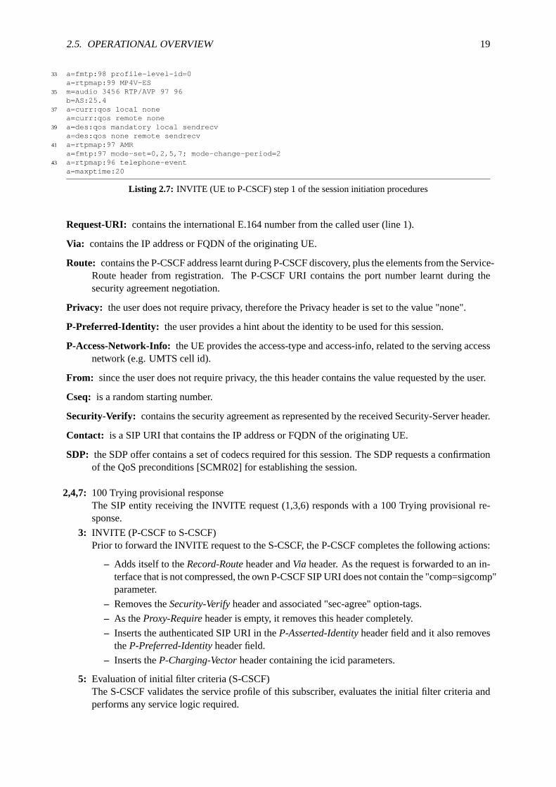
2.5. OPERATIONAL OVERVIEW 19
33 a=fmtp:98 profile-level-id=0a=rtpmap:99 MP4V-ES
35 m=audio 3456 RTP/AVP 97 96b=AS:25.4
37 a=curr:qos local nonea=curr:qos remote none
39 a=des:qos mandatory local sendrecva=des:qos none remote sendrecv
41 a=rtpmap:97 AMRa=fmtp:97 mode-set=0,2,5,7; mode-change-period=2
43 a=rtpmap:96 telephone-eventa=maxptime:20
Listing 2.7: INVITE (UE to P-CSCF) step 1 of the session initiation procedures
Request-URI: contains the international E.164 number from the called user (line 1).
Via: contains the IP address or FQDN of the originating UE.
Route: contains the P-CSCF address learnt during P-CSCF discovery, plus theelements from the Service-Route header from registration. The P-CSCF URI contains the port number learnt during thesecurity agreement negotiation.
Privacy: the user does not require privacy, therefore the Privacy header isset to the value "none".
P-Preferred-Identity: the user provides a hint about the identity to be used for this session.
P-Access-Network-Info: the UE provides the access-type and access-info, related to the servingaccessnetwork (e.g. UMTS cell id).
From: since the user does not require privacy, the this header contains the value requested by the user.
Cseq: is a random starting number.
Security-Verify: contains the security agreement as represented by the received Security-Server header.
Contact: is a SIP URI that contains the IP address or FQDN of the originating UE.
SDP: the SDP offer contains a set of codecs required for this session. The SDP requests a confirmationof the QoS preconditions [SCMR02] for establishing the session.
2,4,7: 100 Trying provisional responseThe SIP entity receiving the INVITE request (1,3,6) responds with a 100Trying provisional re-sponse.
3: INVITE (P-CSCF to S-CSCF)Prior to forward the INVITE request to the S-CSCF, the P-CSCF completesthe following actions:
– Adds itself to theRecord-Routeheader andVia header. As the request is forwarded to an in-terface that is not compressed, the own P-CSCF SIP URI does not contain the "comp=sigcomp"parameter.
– Removes theSecurity-Verifyheader and associated "sec-agree" option-tags.
– As theProxy-Requireheader is empty, it removes this header completely.
– Inserts the authenticated SIP URI in theP-Asserted-Identityheader field and it also removestheP-Preferred-Identityheader field.
– Inserts theP-Charging-Vectorheader containing the icid parameters.
5: Evaluation of initial filter criteria (S-CSCF)The S-CSCF validates the service profile of this subscriber, evaluates theinitial filter criteria andperforms any service logic required.

20 CHAPTER 2. THE IP MULTIMEDIA SUBSYSTEM (IMS)
6: INVITE (S-CSCF to S-CSCF)Before the S-CSCF forwards the INVITE request, as specified by the S-CSCF to S-CSCF proce-dures in [NT05c], the S-CSCF:
– Inserts aRouteheader with its address to ensure the routing to the I-CSCF in the destinationnetwork.
– Adds the identifier of its own network as a Inter Operator Identifier (IOI) parameter of theP-Charging-Vectorheader.
– Inserts the correspondingTEL URL7 to theP-Asserted-Identityheader so that the destinationnetwork is aware of theTEL URL in case PSTN interworking is needed and the INVITE isforwarded to a MGCF.
– Translates8 the Request-URI(From: header) to a globally routable SIP-URL in case theRequest-URI of INVITE request is a TEL-URL (e.g.tel:+12125552222is mapped tosip:[email protected]).
The modifications of the INVITE message are shown in listing 2.8, the remainderof the messagedoes not suffer any change.
1 INVITE sip:[email protected] SIP/2.0Via: SIP/2.0/UDP scscf1.home1.net;branch=z9hG4bK332b23.1, SIP/2.0/UDP pcscf1.visited1.net; ←֓
branch=z9hG4bK240f34.1, SIP/2.0/UDP [5555::aaa:bbb:ccc:ddd]:1357;comp=sigcomp;branch= ←֓z9hG4bKnashds7
3 Max-Forwards: 68Record-Route: <sip:scscf1.home1.net;lr>, <sip:pcscf1.visited1.net;lr>
5 P-Asserted-Identity: "Jack Daniels" <sip:[email protected]>, <tel:+1-212-555-1111>P-Charging-Vector: icid-value="AyretyU0dm+6O2IrT5tAFrbHLso=023551024"; orig-ioi=home1.net
Listing 2.8: INVITE modified headers (S-CSCF to S-CSCF)
8-9,11: 183 Session Progress (UE#2 to UE#1)UE#2 determines the supported set of codecs from those appearing in theSDP offer of the INVITErequest (1)(listing 2.7). The SDP response is sent with a 183 Session Progress response back tothe originator (UE#1).The CSCF (from both origination and destination networks) receiving andforwarding the stores183 Session Progress message store information about this session, foruse in providing enhancedservices, charging or any possible error recovery actions. Listing 2.9shows the information storedat the S-CSCF in the originator network.
Request-URI: sip:[email protected] From: <sip:[email protected]>;tag=171828
To: <tel:+1-212-555-2222>;tag=3141594 Call-ID: cb03a0s09a2sdfglkj490333
CSeq(2dest): 127 INVITE6 CSeq(2orig): none
Route(2dest): <sip:scscf2.home2.net;lr>,<sip:pcscf2.visited2.net;lr>8 Route(2orig): <sip:pcscf1.visited1.net;lr>
Contact(dest): <sip:[5555::eee:fff:aaa:bbb]:8805;comp=sigcomp>10 Contact(orig): <sip:[5555::aaa:bbb:ccc:ddd]:1357;comp=sigcomp>
Listing 2.9: Storage of information at S-CSCF in the originating network
In step 11, the P-CSCF inserts aP-Media-Authorizationheader with the media authorization tokengenerated from the PDF query. The P-CSCF also adds its own SIP URI to theRecord-Routeheaderto insert the secured port number and the sigcomp parameter
7"URLs for Telephone Calls" are defined in IETF RFC 2806.8For this address translation, services of an ENUM-DNS protocol as in RFC 2916 or any other suitable translation database
can be used.

2.5. OPERATIONAL OVERVIEW 21
10: Authorization of QoS ResourcesThe P-CSCF authorizes the resources necessary for this session querying the PDF. The approval ofQoS commitment can either happen at this step or in (36) after reception of the final 200 OK. Thisaction is based on operator local policy. More details about the authorization and commitment arepresented in chapter 3.2.6.
12,14-15: PRACK (UE to P-CSCF)UE#1 determines which media flows and correspondent codecs should beused for this session.If there was any change in media flows, or if there was more than one choiceof codec for amedia flow, then the UE#1 includes a new SDP offer in a provisional acknowledgement message(PRACK) sent to UE#2.
13: Resource Reservation (UE and Access Network)After determining the media streams in step 12 the UE initiates the reservation procedures for theresources needed for this session.
16-18: 200 OK response (UE#2 to UE#1)The destination endpoint acknowledges the PRACK request (12) with a 200 OK response. The200 OK message is forwarded via the signaling path established by the INVITE request. to theUE#1.
19-21: UPDATE (UE to P-CSCF)Once the resource reservation (13) is completed, the UE sends an UPDATE request to the terminat-ing endpoint informing about the currently status of the QoS resource reservation. This indicationis reflected in the change of thecurr:qos localprecondition tag [SCMR02] fromnoneto sendrecvas shown in listing 2.10.
...2 a=curr:qos local sendrecv
a=curr:qos remote none4 ...
Listing 2.10: Changes in the SDP body of the UPDATE message after resource reservation completed.
When forwarding the UPDATE request to the S-CSCF, the P-CSCF adds charging information forthis session in theP-Charging-Vectorheader. In case of a GPRS access network, an example ofthe charging information is shown in listing 2.11:
P-Charging-Vector: icid-value="AyretyU0dm+6O2IrT5tAFrbHLso=023551024"; ggsn=[5555 ←֓::4b4:3c3:2d2:1e1]; auth-token=2A96B3AF30D1;
2 pdp-info="pdp-item=1; pdp-sig=no; gcid= A93D238CAF; flow-id=({1,1},{1,2}), pdp-item=2; ←֓pdp-sig=no; gcid=F312D5E3BC;
flow-id=({2,1},{2,2})"
Listing 2.11: P-Charging-Vector header example.
22-24: 200 OK response (UE#2 to UE#1)The destination endpoint acknowledges the UPDATE request (19) with a 200 OK response throughthe established signaling path.
25-27: 180 Ringing (optionally) (UE#2 to UE#1)Optionally, the called UE may perform alerting signaling this by sending a provisional 180 (Ring-ing) response to the calling UE.
28-30: PRACK (UE#1 to UE#2)The UE#1 acknowledges the reception of the 180 (Ringing) provisional response (27) with aPRACK request.
31-33: 200 OK (UE#2 to UE#1)The destination endpoint responds to the PRACK request with a 200 (OK) response.
34-35,37: 200 OK (UE#2 to UE#1)When the called party answers, the terminating endpoint sends a 200 (OK) final response to the

22 CHAPTER 2. THE IP MULTIMEDIA SUBSYSTEM (IMS)
initial INVITE request sent by UE#1 (1).
36: Approval of QoS Commit (UE#2 to UE#1)The P-CSCF approves the commitment (see chapter 3.2.6) of the QoS resources if it was notapproved already in step (10).
38-40: ACK (UE#1 to UE#2)The UE starts the media flow for this session and acknowledges to the 200 (OK) response (37)with an ACK request sent to UE#2.

2.5. OPERATIONAL OVERVIEW 23
P- CSCF UE #1 S- CSCF CSCFs
1. INVITE
5. Evaluation of Initial Filter Criteria
Visited network Home Network
2. 100 Trying
Terminating Network
UE #2
4. 100 Trying
3. INVITE
6. INVITE
7. 100 Trying
8. 183 Session in progress 9. 183 Session in progress
11. 183 Session in progress
10. QoS Authorization
12. PRACK
14. PRACK 15. PRACK 13. Resource Rsv.
16. 200 OK 17. 200 OK
18. 200 OK
19. UPDATE 20. UPDATE
21. UPDATE
22. 200 OK 23. 200 OK
24. 200 OK 25. 180 Ringing
27. 180 Ringing 26. 180 Ringing
28. PRACK 29. PRACK
30. PRACK
31. 200 OK 32. 200 OK
33. 200 OK 34. 200 OK 35. 200 OK
37. 200 OK
36. QoS Approval
38. PRACK 39. PRACK
40. PRACK
Figure 2.5: Session initiation procedures in a roaming scenario as specified in [NT05c].

24 CHAPTER 2. THE IP MULTIMEDIA SUBSYSTEM (IMS)
Chapter 3
Analysis of IMS based convergence
The IP Multimedia Subsystem (IMS) defined by 3GPP provides an enabling architecture that is accessindependent. This is critical in the move towards convergence. Now each access type is being enabledto work with an IMS core, be it DSL, WLAN, UMTS or any emerging technology, such as WiMAX.
As a result of IMS becoming the convergence architecture of choice, a number of standards bodiesare involved in defining converged architectures in both fixed and wireless networks.
Fixed Mobile Convergence (FMC) implies convergence of fixed and mobile networks to work irre-spective of location, access technology or requested services. This chapter introduces the FMC conceptand requirements followed by a study of IMS features regarding these requirements.
3.1 Fixed mobile convergence and Next Generation Networks
A Next Generation Network (NGN) is defined by the International Telecommunication Union (ITU) asfollows [IT04, Rec. Y.2001]:
A packet-based network able to provide telecommunication services and able to makeuseof multiple broadband,QoS-enabled transport technologies and in whichservice-relatedfunctions areindependent from underlyingtransport-relatedtechnologies. It enablesunfetteredaccess for users to networks and to competing service providers and/orservices of theirchoice. It supportsgeneralizedmobility which will allowconsistentandubiquitousprovisionof servicesto users.
With Internet Protocol (IP) technology commonly deployed in actual packet networks, a NGN is anall-IP Network (AIPN) as defined per 3GPP in [SA05b]:
A collection ofentities that provide a set of capabilities for theprovisionof IP services tousers based on IP technology wherevariousaccesssystems can be connected. The AIPNprovides a set ofcommoncapabilities (including mobility, security, service provisioning,charging and QoS) which enable the provision of services to users andconnectivity to otherexternal networks.
NGN means the convergence of the fixed and the mobile telecommunications worldat differentlevels. A definition of FMC by ETSI [ETS98] is:
Fixed and Mobile Convergence (FMC) is concerned with theprovision of network andservicecapabilities, which areindependentof the accesstechnique. This does not neces-sarily imply the physical convergence of networks. It is concerned withthe development ofconvergednetworkcapabilities and supporting standards. Thissetof standards may be used
25

26 CHAPTER 3. ANALYSIS OF IMS BASED CONVERGENCE
to offer a set ofconsistentservices viafixedor mobile access to fixed or mobile, public orprivate networks.
The main feature of the FMC is to allow users to access a consistent set of services fromany fixed or mobile terminal via any compatible access point. Extending this concept in aroaming scenario, the users should be able to roam between different networks and use thesame services through those visited networks. This feature is referred to as the Virtual HomeEnvironment (VHE).
It can be sayed that FMC is the matching of fixed network, mobile network andspectrum resourcesin order to meet end-user demand for mobile, voice, data, video and value added services.
3.1.1 Motivation for convergence
In recent years, it has become evident that a number of forces were leading operators towards conver-gence. Services can be used from a wide range of devices and userswere claim for a uniform access toservices independent of the type of access network and terminal being used.
Wireline providers are experimenting a declining of revenues (e.g. through VoIP, flat rates, mobilecommunications) and started to consider ways to access the wireless revenues and update their obsoletelegacy networks. Telephone services currently offered by mobile operators providing users with a fixedphone number to be used with their handsets (e.g. o2 Genion, T-Mobile@home) clearly compete in ser-vice and rates with traditional fixed line operators. On the other side, wireless operators aim to continuetheir market expansion, adding to the sales of handsets and new converged business services. From atelecom provider point of view, costs and services are from vital importance:
Lower infrastructure and maintenance costs: An IP based converged network means the Circuit SwitchedCore Network (CSCN) is no longer necessary. Open standards and competition are the reasonswhy IP network components cost less compared to telephony equipment. Therefore, convergenceresults in lower capital expenditure (CAPEX) for operators. Moreover, provider can remove re-dundant components that perform the same functions in both networks.
Converged network functions based on IP results in reduced maintenance and operations costs(OPEX). The open standard management of IP networks is easier and therefore cheaper in com-parison to legacy circuit switch networks. One signaling and bearer network reduces the costs ofdeveloping expertise in multiple technologies.
Enhanced services and rapid service deployment:The integration of voice and data networks offersopportunities for deploying enhanced multimedia services. In our days, Internet already offers acompetitive set of enhanced services and providers need to compete against and at the same timeprofit from that. A combination of Internet and telephony services opensnew revenue sourcesopportunities for service providers.
Single standards in a converged network allow for rapid deployment of new services. The devel-opment and adaptation required to introduce new services is reduced dueto the integrated networkmanagement in NGN.
3.1.2 Service, device and network convergence
FMC can be seen from the services, devices and network convergence perspectives [Ame05, EUR99]:
Service convergence:Service convergence focuses on end-user requirements and the service experi-ence. The primary goal of service convergence is the concurrent delivery of all media types (voice,data, and video) in an easy to use user interface, with mobility and access and device awareness. Amultitude of services (person-to-person, person-to-content, and content-to-person) can be providedto the same user over different access networks and to different devices.

3.2. ANALYSIS OF IMS ON FIXED MOBILE CONVERGENCE 27
Device convergence:The Always Best Connected [GJ03] concept: anywhere and anytime and by de-vice of choice and when on the move. Devices such as traditional cellular phones have historicallybeen devices with few functionalities. Presently, convergence in consumer electronics is com-bining many functions into single devices. End users will profit from extended functionality inthe same mobile device (e.g. camera, multimedia streaming and storage, gaming, E-mail, web,applications, true OS, etc).
Next generation multi-access devices will be provided intelligent access network selection func-tions. These multi-radio functionality will gain importance and will not be limited to enhancefrom the coverage and data rates (GSM+TDMA, or GSM/EDGE+WCDMA) but will support newtechnologies like WLAN or WiMAX. Overall, there is a clear need to enable ubiquitous accessfrom the user’s preferred device.
Network convergence: Network convergence involves a unified core network, access networks thatcomplement each other, and common multi-access aware service delivery platforms. A core net-work based on IP for the transport plane will enable the bridging of diverse fixed and wirelesstechnologies.
Network convergence is the enabler to facilitate better access to value-added services and appli-cations. This requires investment from the network operator to deploy the technologies at thenetwork operator’s side that allow the provision of value-added services with telecom-grade qual-ity of service. Despite of the initial capital expenses required, a unified transport network withcommon network functions will increase the cost efficiency of new services delivery and deploy-ment. Technologies such as Unlicensed Mobile Access (UMA) [uma06] or VoIP, and enablingmachinery such as IMS, will be the driving forces of network convergence.
3.2 Analysis of IMS on fixed mobile convergence
This chapter analyzes the IMS specified by 3GPP regarding a series of requirements of FMC networks.IMS is being regarded as the brain of NGN enabling the integration of multiple access technologies. Thisconvergence requires the consideration of many challenging issues.
From the fixed access networks ETSI TISPAN is working on adoption of IMS for their NGN [tis06].They are studying the impacts of the use of IMS for fixed access. The analysis is based on the con-siderations of ETSI TISPAN and the requirements of the FMC paradigm. First a set of requirements isestablished and then an evaluation of the IMS features presents how far the identified requirements aremet.
Where possible, modifications on the IMS to support non-3GPP access networks will be provided.At the end, requirements of a fixed and a mobile provider with respect to the necessary enhancements inaccess and transport networks to support IMS are presented.
3.2.1 Requirements
From the definition and concepts of FMC a large list of system requirements can be derived. Whenconsidering fixed mobile convergence it is perhaps equally important to understand the requirementsimposed by the end-users as well as the technical requirements of the service, network and device con-vergence. The identification of requirements is simplified by dividing them into 5categories:
1. Convenience and ease of use:requires simplified processes for identification and billing.
2. Service transparency:offers service and personal mobility support.
3. Network convergence:allows sharing of network resources.
4. Security: provides combined access control, authentication and security mechanisms.
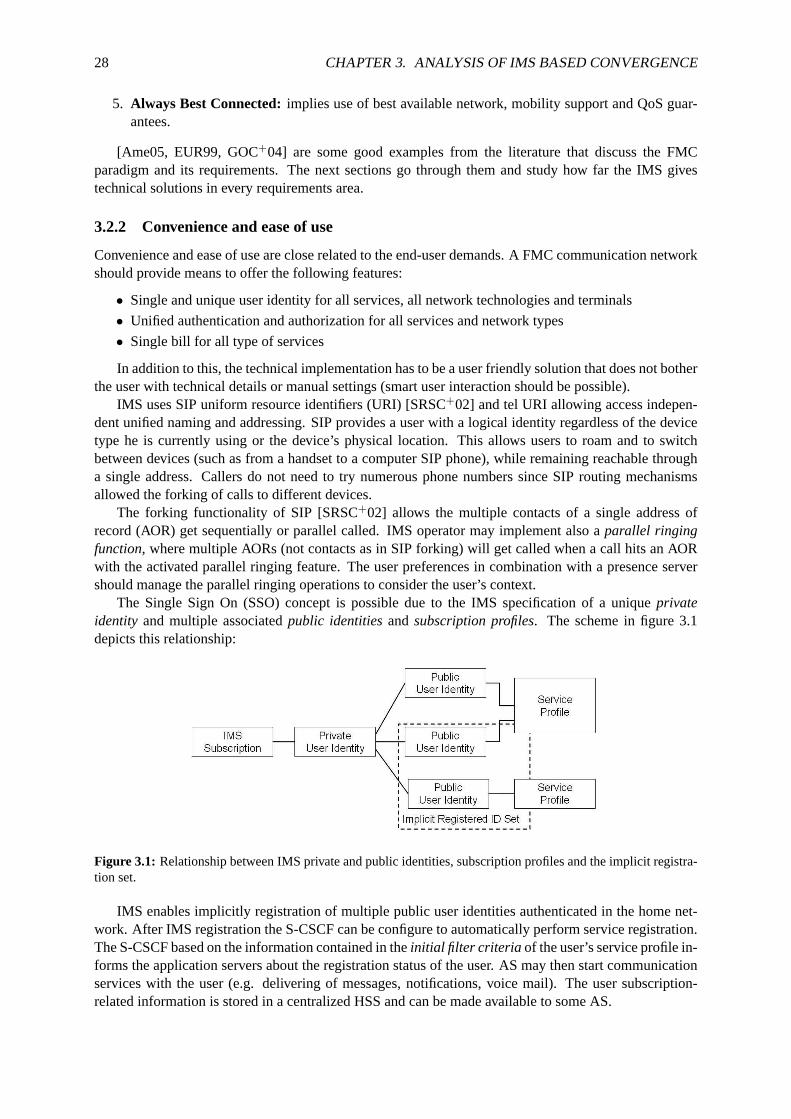
28 CHAPTER 3. ANALYSIS OF IMS BASED CONVERGENCE
5. Always Best Connected:implies use of best available network, mobility support and QoS guar-antees.
[Ame05, EUR99, GOC+04] are some good examples from the literature that discuss the FMCparadigm and its requirements. The next sections go through them and study how far the IMS givestechnical solutions in every requirements area.
3.2.2 Convenience and ease of use
Convenience and ease of use are close related to the end-user demands. A FMC communication networkshould provide means to offer the following features:
• Single and unique user identity for all services, all network technologies and terminals
• Unified authentication and authorization for all services and network types
• Single bill for all type of services
In addition to this, the technical implementation has to be a user friendly solution that does not botherthe user with technical details or manual settings (smart user interaction should be possible).
IMS uses SIP uniform resource identifiers (URI) [SRSC+02] and tel URI allowing access indepen-dent unified naming and addressing. SIP provides a user with a logical identity regardless of the devicetype he is currently using or the device’s physical location. This allows users to roam and to switchbetween devices (such as from a handset to a computer SIP phone), while remaining reachable througha single address. Callers do not need to try numerous phone numbers since SIP routing mechanismsallowed the forking of calls to different devices.
The forking functionality of SIP [SRSC+02] allows the multiple contacts of a single address ofrecord (AOR) get sequentially or parallel called. IMS operator may implement also aparallel ringingfunction, where multiple AORs (not contacts as in SIP forking) will get called when a call hits an AORwith the activated parallel ringing feature. The user preferences in combination with a presence servershould manage the parallel ringing operations to consider the user’s context.
The Single Sign On (SSO) concept is possible due to the IMS specification ofa uniqueprivateidentity and multiple associatedpublic identitiesandsubscription profiles. The scheme in figure 3.1depicts this relationship:
Figure 3.1: Relationship between IMS private and public identities, subscription profiles and the implicit registra-tion set.
IMS enables implicitly registration of multiple public user identities authenticated in the home net-work. After IMS registration the S-CSCF can be configure to automatically perform service registration.The S-CSCF based on the information contained in theinitial filter criteria of the user’s service profile in-forms the application servers about the registration status of the user. AS may then start communicationservices with the user (e.g. delivering of messages, notifications, voice mail). The user subscription-related information is stored in a centralized HSS and can be made available to some AS.
3.2. ANALYSIS OF IMS ON FIXED MOBILE CONVERGENCE 29
Thechargingcapabilities of IMS are almost unlimited and are specified in [SA05a]. The separationof service and transport planes allows different charging schemes attransport layer and IMS (serviceand content) levels. Due to the flexibility of the SIP signaling, IMS charging capabilities includeonlineandoffline charging1, event charging (e.g. messaging), per media component charging (by inspectionof SDP) or calling/called party charging models. IMS charging provides operators to be more than "bitpipe" provider.
Since all user identities are related to a single private ID, a single billing systemfor all types ofservices is possible. Though IMS enables all these billing capabilities, a real world deployment ofsingle billing is very complex. Different billing mechanisms from deployed access networks need to beaccommodated (see charging correlation in the FMC issues description of chapter 3.3.4).
3.2.3 Service transparency
Users expect seamless transparency of features and continuity of services as they roam between loca-tions covered by different communication technologies (e.g. WLAN, GSM) as well as convergencebetween mobile and wireline devices. Additionally, service transparency is needed to manage incom-ing and outgoing communications on any device based on the user’s context.This context can includeuser’s availability and location, terminal capabilities and user preferences. From a service perspective,following requirements have been identified:
• Personal and service mobility support
• Support of a wide spectrum of services
• Adaptation of network and/or applications
SIP enables service andpersonal mobility, independent of the used network to access the IMS. Per-sonal mobility is achieved by the SIP addressing scheme as previously described in chapter 3.2.2 withregards to convenience and easy of use.
Service mobilityrefers to the end user’s ability to maintain ongoing sessions and obtain services ina transparent manner regardless of the end user’s point of attachment.The service mobility includes theability of the home service provider to either maintain control of services it provides to the user in thevisited network or transfer their control to the visited network. The services should have the "same lookand feel" even in different networks. This ability appears in the definition of FMC in chapter3.1 and isreferred to as the Virtual Home Environment (VHE)2.
Means forpersonalizationare required to make user’s presence and preferences always availableoffering the user the capability of"having access to my data, through my preferred device, when I want it,where I want it."The two main objectives of personalization and provision of a VHE strive to [EUR99]:
1. Maintain the QoS of ongoing sessions as the user roams around heterogenous networks.
2. Ensure that the mobile user has access to all of its subscribed network services and features.
IMS service architecture allows the provision of a VHE through the implementationof services inthe home network. Thus, service knowledge is not required in the visited network. Figure 3.2 shows howthe service interworking between different providers is simplified by the IMS layered architecture (figure3.3 shows the horizontal service integration). The IMS Service Control (ISC) interface that connects S-CSCF with AS allows flexible third party service deployment increasing the range of services offered tothe user and maintaining the control over user’s services.
By having the user related information stored in the HSS, the IMS offers capabilities to managethe user’s environment. The user environment is defined as the "accessnetwork and terminal". The
1In online charging the user effectively pre-pays for a service while in offline charging a user is billed after the service.Thus, the first charging method is implemented as a "pay-as-you-go" system (e.g. prepaid cards), whereas the second methodis implemented where the user billing for used services happens at regular intervals (e.g. monthly billing).
2In the literature this feature also appears referred to as User Home Environment (UHE).

30 CHAPTER 3. ANALYSIS OF IMS BASED CONVERGENCE
Figure 3.2: IMS architecture simplifies the interconnection agreements between telecom providers. Source Erics-son.
definition of this environment allows a roaming user to get his services basedon a combination of hissubscription parameters and the technical constraints of the access and network being used. Accessnetwork information is provided at the time of IMS registration by including this information in SIPprivate headers. Based on these identifiers the S-CSCF an AS can adapt the provision of services to theuser environment characteristics. This function is of major importance in a heterogeneous environment,while homogeneous systems do not require such data because they are implicitly the same for all users.
The centralized HSS subscription database includes information such as: repository data, IMS publicidentities, IMS user state, initial filter criteria, location information, charging information, subscriptionprofiles, etc.
S-CSCF uses theinitial filter criteria to involve AS(s) as needed to provide services and features.The S-CSCF forwards messages to each AS in the order indicated by the filter criteria received from theHSS in the subscriber’s service profile. After the last AS is contacted, then the message is sent to theintended destination. IMS defines Service Point Triggers (SPTs), pointsin the SIP signaling on whichinitial filter criteria can be set, including:
1. Any initial known or unknown SIP method (e.g. REGISTER, INVITE, MESSAGE, etc.)
2. Presence or absence of any header or its contents
3. Direction of the request with respect to the served user (origination ordestination)
4. Registration status of the user
5. Session description information (e.g. any property in the SDP)
It is important to remark that 3GPP standardizes IMS service capabilities notthe services themselves(following the principles of SIP). IMS standardization focuses primarily onthe IMS core network formultimedia session control, including real time and messaging services. It is the Open Mobile Alliance(OMA) [oma] who investigates the applications space by standardizing service enablers (e.g. presence,directory, media handling, etc.) on top of IMS.
Nonekiller servicesbased on IMS are yet available, but there is a common belief that connectivityis thekiller servicein NGN. IMS is also usually referred as akiller service delivery platform because ofits feature allowing:
• Sharing of common resources (services enablers)
• Seamless integration of legacy and emerging services
• Flexible and easy creation of new services (support for different service platforms through the ISCreference point [SA05c])

3.2. ANALYSIS OF IMS ON FIXED MOBILE CONVERGENCE 31
• Third party service support (developers and providers)
The SDP negotiation is a key feature that allows the adaptation of communication sessions to enddevice capabilities or changes in the media (e.g. due to changes in the networkconditions). The provisionof network based adaptation functions is also required to allow per se incompatible user applicationsto interconnect [SSSTK06]. Once again the service architecture of IMSeases the definition of suchadaptation functions by calling the required AS when incompatibilities are detected.
3.2.4 Network convergence
The concept of network convergence has been presented in chapter3.1.2. The requirements on thenetwork layer can be basically summarized in:
• Common network control and support functions
• Common transport networks
• Inter working with other networks (legacy support, other operator’s IMS)
A converged network using IMS allows the following resources to be shared, regardless of service oraccess type (see figure 3.3):
• Charging (common subscription profiles)
• Presence and location (unified naming and addressing)
• Directory (group and list functions)
• Provisioning (control of QoS)
• Media handling (interworking with other networks such as PSTN)
• Session control (session management)
• Operation and management
• Security (authentication and authorization)
Figure 3.3: IMS architecture allows sharing of network resources independent service or access type. SourceTISPAN.
This set of resources are once defined by IMS and can be reused byservices based on IMS. There isno need any more to define network functions such as charging, QoS policing, authentication and autho-rization, location and addressing, etc. for each service upon IMS. Furthermore, services are supposed to

32 CHAPTER 3. ANALYSIS OF IMS BASED CONVERGENCE
interact with each other reducing the duplication of functionalities and increasing the user’s experience.One example of such a service interworking ispresence. A presence server makes the location and statusinformation of user available to other services requiring this information. Thismade include, registereduser identities, available devices and capabilities, context information etc.
IMS layered architecture separates access from service plane. The separation of signaling and datapath increases the efficiency and flexibility. Furthermore, the layered architecture allows the use ofa core IP based common transport network for all services and accesstypes. A so calledhorizontalintegrationis achieved through the replication of common network functions and routing and discoverymechanisms for all IMS services. In traditional networks services are vertical vertically integrated,functions at different layers need to defined for each service (see figure 3.4). IMS reduces thus requiringthe efforts in service implementation and maintenance.
Figure 3.4: IMS horizontal integration through replication of common functions. Source Ericsson.
The I-CSCF acts as an inter IMS contact point and routes incoming and outgoing SIP signaling. Butin same cases the destination party can be out of the IMS network, for example a fixed phone in thelegacy telephone network.
Interworking with the Public Switched Telephony Network (PSTN): SIP Invite messages are routedto the serving S-CSCF of the originator user. The S-CSCF, possibly in conjunction with an ApplicationServer, shall determine if the session should be forwarded to an external network such as the PSTN. If so,the Invite request is forwarded to the BGCF in the same network responsiblefor selecting the network inwhich the interworking should occur. This process can be based on local policy based depending of thedestination address (To: SIP URI or tel URI).
If the BGCF determines that the interworking should occur in the same network, then the BGCFselects the MGCF which will perform the interworking, otherwise the BGCF forward the invite informa-tion flow to the BGCF in the selected network. The MGCF will perform the interworking to the PSTNand control (SIP to PSTN signaling e.g. SS7) the MG for the media conversions (RTP to e.g. G.711 au-dio codec). [KH02] analyzes how breaking out to external networks and passing through several mediagateways considerably increases the signaling delay. The high level routing process is shown in figure3.53.
Interworking with the Internet: With current SIP specifications of IETF and 3GPP interoperabilityis difficult to achieve. SIP clients and servers software must be modified if they are to be used in IMSnetwork. The essential interfaces regarding SIP are:
3Note that Global Switched Telephony Network (GSTN) equals a PSTN

3.2. ANALYSIS OF IMS ON FIXED MOBILE CONVERGENCE 33
Figure 3.5: High level overview of the network based GSTN interworking breakout process as in [SA05c].
• Gm-interface between the UE and the P-CSCF
• ISC-interface between the S-CSCF and the AS
• Mm-interface between IMS and other SIP networks
Due to the SIP use in 3GPP as described in chapter 2.4.3, available SIP clientsneed modificationsto access IMS services and available SIP servers require changes to be used as application servers inthe IMS. Some kind of SIP version adaptation is required to ensure interoperability. However, the stan-dardization of the Mm interface from IMS to other SIP networks such as theInternet is still an ongoingprocess. Interoperability between the IMS and the Internet would allow possibility of multimedia ses-sions between Internet and IMS users. To overcome interoperability issues, 3GPP and IETF have tocooperate to address current access network dependencies, further discussed in chapter 3.3.1, that in-clude SIP end-to-end communications, new SIP header fields and signalingprocedures and different SIPtimers.
3.2.5 Security
Security is very important in the wired and Internet worlds as well as in mobile networks. End-usersexpect the same or better safeguards for their converged communicationsas in traditional voice services.Security should be provided in the converged networks no matter what device or access network is used.Means to prevent spam, viruses, or fraud are also very valuable. In addition to this, it is also be veryimportant to be able to identify the issuer of a communications session as well as the user’s ability toaccept or deny it.
• Combined authorization and authentication mechanisms
• Means to guarantee non-repudiation, privacy, and integrity
IMS based networks split the authentication in two parts:
1. User authentication for services is done in the core network (home subscriber network).
2. Terminal authentication granted by the access network that provides connectivity.
While in the second part the device capabilities and access network technology determine the avail-able authentication procedures, the identification of user is done at a higher level by the IMS in the user’s
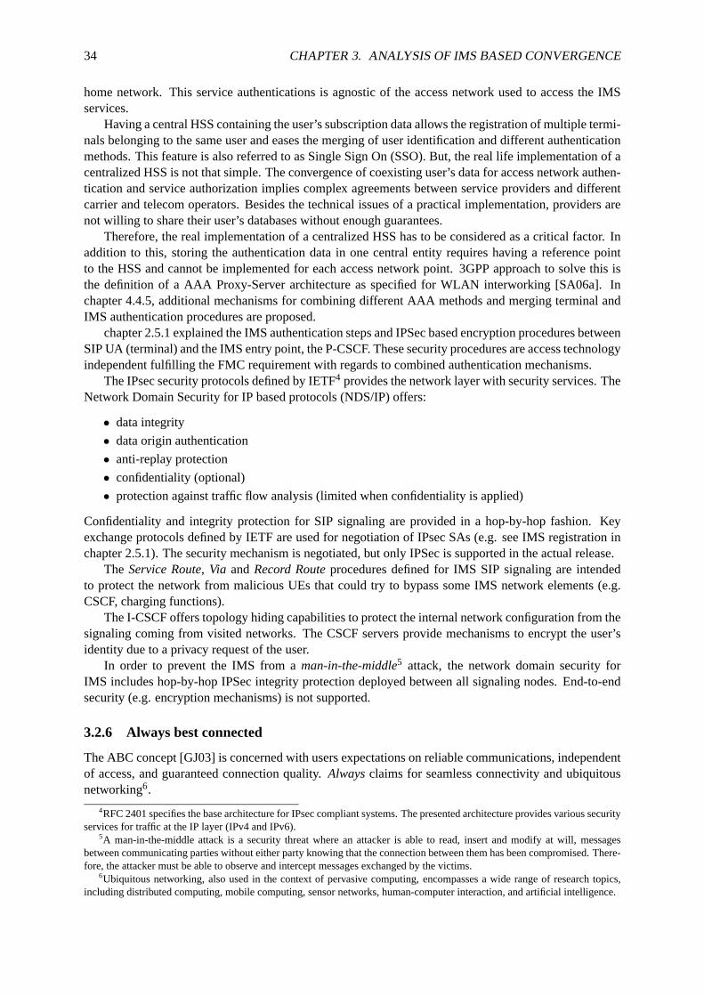
34 CHAPTER 3. ANALYSIS OF IMS BASED CONVERGENCE
home network. This service authentications is agnostic of the access network used to access the IMSservices.
Having a central HSS containing the user’s subscription data allows the registration of multiple termi-nals belonging to the same user and eases the merging of user identification and different authenticationmethods. This feature is also referred to as Single Sign On (SSO). But, the real life implementation of acentralized HSS is not that simple. The convergence of coexisting user’sdata for access network authen-tication and service authorization implies complex agreements between service providers and differentcarrier and telecom operators. Besides the technical issues of a practical implementation, providers arenot willing to share their user’s databases without enough guarantees.
Therefore, the real implementation of a centralized HSS has to be considered as a critical factor. Inaddition to this, storing the authentication data in one central entity requires having a reference pointto the HSS and cannot be implemented for each access network point. 3GPP approach to solve this isthe definition of a AAA Proxy-Server architecture as specified for WLANinterworking [SA06a]. Inchapter 4.4.5, additional mechanisms for combining different AAA methods and merging terminal andIMS authentication procedures are proposed.
chapter 2.5.1 explained the IMS authentication steps and IPSec based encryption procedures betweenSIP UA (terminal) and the IMS entry point, the P-CSCF. These security procedures are access technologyindependent fulfilling the FMC requirement with regards to combined authentication mechanisms.
The IPsec security protocols defined by IETF4 provides the network layer with security services. TheNetwork Domain Security for IP based protocols (NDS/IP) offers:
• data integrity
• data origin authentication
• anti-replay protection
• confidentiality (optional)
• protection against traffic flow analysis (limited when confidentiality is applied)
Confidentiality and integrity protection for SIP signaling are provided in a hop-by-hop fashion. Keyexchange protocols defined by IETF are used for negotiation of IPsecSAs (e.g. see IMS registration inchapter 2.5.1). The security mechanism is negotiated, but only IPSec is supported in the actual release.
The Service Route, Via andRecord Routeprocedures defined for IMS SIP signaling are intendedto protect the network from malicious UEs that could try to bypass some IMS network elements (e.g.CSCF, charging functions).
The I-CSCF offers topology hiding capabilities to protect the internal network configuration from thesignaling coming from visited networks. The CSCF servers provide mechanisms to encrypt the user’sidentity due to a privacy request of the user.
In order to prevent the IMS from aman-in-the-middle5 attack, the network domain security forIMS includes hop-by-hop IPSec integrity protection deployed between allsignaling nodes. End-to-endsecurity (e.g. encryption mechanisms) is not supported.
3.2.6 Always best connected
The ABC concept [GJ03] is concerned with users expectations on reliable communications, independentof access, and guaranteed connection quality.Alwaysclaims for seamless connectivity and ubiquitousnetworking6.
4RFC 2401 specifies the base architecture for IPsec compliant systems.The presented architecture provides various securityservices for traffic at the IP layer (IPv4 and IPv6).
5A man-in-the-middle attack is a security threat where an attacker is able to read, insert and modify at will, messagesbetween communicating parties without either party knowing that the connection between them has been compromised. There-fore, the attacker must be able to observe and intercept messages exchanged by the victims.
6Ubiquitous networking, also used in the context of pervasive computing,encompasses a wide range of research topics,including distributed computing, mobile computing, sensor networks, human-computer interaction, and artificial intelligence.

3.2. ANALYSIS OF IMS ON FIXED MOBILE CONVERGENCE 35
Reliability and security must be maintained by the operator by ensuring the same QoS in futurenetworks that the user experience today. Connection quality expectationsare quite low in mobile com-munications and require improvements in order for services and applications toseamlessly exist in aconverged communications world.Bestvaries according to user preferences and used services, Qual-ity of Experience (QoE) and price. The use of the best available network(based on user’s preferencerules, context information, user interaction, etc.) is expected. The following requirements need to beaddressed:
• Network guarantees on end-to-end QoS
• Inter-technology access support (access-device independent services)
• Seamless service continuity (enhanced inter-technology terminal mobility support)
It is the IMS framework that guarantees transparent end-to-end aspects to the end-user: mappingQoS parameters and security methods, as well as applications methods. QoS guarantees in the accessnetworks can be complemented withDiffServenabled core network guarantying end-to-end quality ofservice.
Quality of Service in IMS
3GPP has adopted a layered QoS architecture that defines how applicationQoS requirements are mappedto appropriate Bearer Service (BS). The BS describes how a given network defines and provides QoS inits layer. Each BS relies on the QoS-enabled services of the lower layers.Chapter 3.2.6 provides furtherdetails on the QoS layered architecture. 3GPP specifies four classes of traffic:
• Conversational traffic requires a guaranteed bitrate with low latency (e.g. real time applicationssuch as voice and video conferencing).
• Streaming traffic needs a guaranteed bitrate and tolerant delay (e.g. video streaming).
• Interactive traffic applies for services requiring some assured throughput in orderto provide goodresponse time (e.g. web browsing).
• Background traffic classes correspond to burst traffic with various priorities, but without a guar-anteed bitrate (e-mail).
In IMS during the call setup handled by SIP the access network has to provide the required resources.To ensure this, Ta Policy-based QoS control in IMS has been split between two entities: the PolicyDecision Function (PDF) and the Policy Enforcement Point (PEP). The PDF takes a service level policyrequest from the application layer (e.g. the SDP of an INVITE is passed from the P-CSCF to the PDF)and the PDF translates it into IP QoS parameters (e.g. a G.711 call would be translated into real-timepriority with 80 kbps IP bandwidth required). The access network is then asked if it can provide thisQoS. How this is done and the next steps depend on the type of access network used.
Once authorized and approved, the network must guarantee that these resources are made availableto the legitimate users. An IMS session ensuring QoS must go through the following steps during setup:
1. Authorization of resources: During an IMS session setup the P-CSCF examines the media descrip-tion in the SIP message and queries the PDF if the required QoS can be authorized. The QoSquery to the PDF is done using the Diameter protocol [SCLG+03]. If authorized, the PDF answerswith an authorization token and the P-CSCF includes the token in theP-Media-Authorizationtag[SMar03] of the SIP message. The token will be used later by the UE to proof to the PEP thevalidity the of requested resources. The media policy features include:
• network-wide policies, which are typically enforced by the P-CSCF (e.g. barring of certain high-bandwidth codecs).
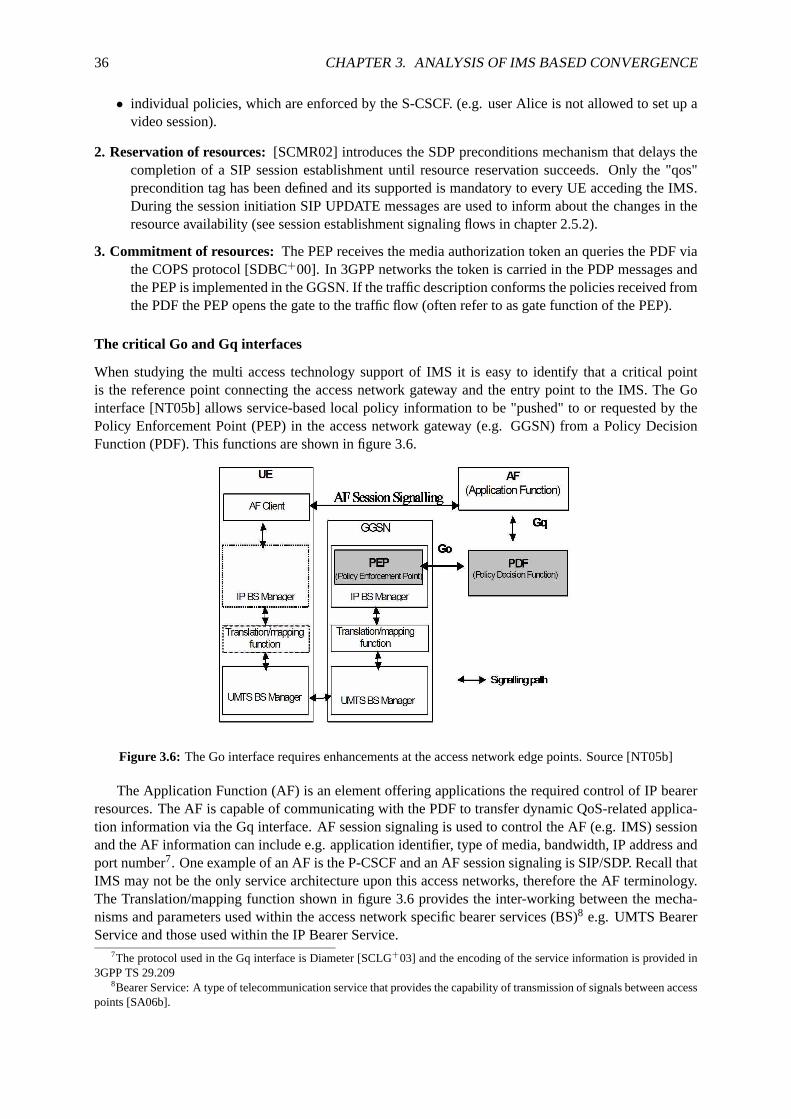
36 CHAPTER 3. ANALYSIS OF IMS BASED CONVERGENCE
• individual policies, which are enforced by the S-CSCF. (e.g. user Aliceis not allowed to set up avideo session).
2. Reservation of resources:[SCMR02] introduces the SDP preconditions mechanism that delays thecompletion of a SIP session establishment until resource reservation succeeds. Only the "qos"precondition tag has been defined and its supported is mandatory to every UE acceding the IMS.During the session initiation SIP UPDATE messages are used to inform aboutthe changes in theresource availability (see session establishment signaling flows in chapter 2.5.2).
3. Commitment of resources:The PEP receives the media authorization token an queries the PDF viathe COPS protocol [SDBC+00]. In 3GPP networks the token is carried in the PDP messages andthe PEP is implemented in the GGSN. If the traffic description conforms the policiesreceived fromthe PDF the PEP opens the gate to the traffic flow (often refer to as gate function of the PEP).
The critical Go and Gq interfaces
When studying the multi access technology support of IMS it is easy to identify that a critical pointis the reference point connecting the access network gateway and the entry point to the IMS. The Gointerface [NT05b] allows service-based local policy information to be "pushed" to or requested by thePolicy Enforcement Point (PEP) in the access network gateway (e.g. GGSN) from a Policy DecisionFunction (PDF). This functions are shown in figure 3.6.
Figure 3.6: The Go interface requires enhancements at the access network edge points. Source [NT05b]
The Application Function (AF) is an element offering applications the required control of IP bearerresources. The AF is capable of communicating with the PDF to transfer dynamic QoS-related applica-tion information via the Gq interface. AF session signaling is used to control theAF (e.g. IMS) sessionand the AF information can include e.g. application identifier, type of media, bandwidth, IP address andport number7. One example of an AF is the P-CSCF and an AF session signaling is SIP/SDP.Recall thatIMS may not be the only service architecture upon this access networks, therefore the AF terminology.The Translation/mapping function shown in figure 3.6 provides the inter-working between the mecha-nisms and parameters used within the access network specific bearer services (BS)8 e.g. UMTS BearerService and those used within the IP Bearer Service.
7The protocol used in the Gq interface is Diameter [SCLG+03] and the encoding of the service information is provided in3GPP TS 29.209
8Bearer Service: A type of telecommunication service that provides the capability of transmission of signals between accesspoints [SA06b].

3.3. 3GPP AND TISPAN ARCHITECTURAL AND FUNCTIONAL CONVERGENCE 37
SIP sessions can handle multiple media simultaneously, that means different QoS requirements andIP addresses and ports need to be managed for a single session. This is ahuge challenge for accessnetworks. They need to be capable of handling each media stream separately for charging, resourcesreservations or authorization purposes. For 3GPP that meant the need todefine an additional parameter toforce the set up of a new PDP context for each new media stream in the session. Other access technologiesneed to define and implement the required changes in their access systems to meet their own policingrequirements.
3.3 3GPP and TISPAN architectural and functional convergence
This section introduces the fundamental characteristics of 3GPP and TISPAN architectures. A compari-son of both architectures is required to understand the inherent differences of both access networks.
The 3GPP PS Domain GPRS procedures for IP connectivity service, authentication and locationmanagement are replaced in TISPAN by the Network Attachment SubSystem (NASS) having the fol-lowing main functionalities:
• IP address allocation (e.g. using DHCP)
• Authentication, taking place at the IP layer (prior or during the address allocation procedure)
• Authorization of network access (based on user profiles)
• Location management, taking place at the IP layer
Resource control is done at the Resource and Admission Control Sub-System (RACS) in conjunctionwith the Resource Control Enforcement Function (RCEF) and Border Gateway Function (BGF) entitiesand includes the following functionality:
• Admission control
• Resource reservation
• Policy control
• NAT traversal
Session control is responsibility of the IMS regardless from the type of access network used. Thisaccess independence for the cases of GPRS, WLAN and DSL networksis depicted in figure 3.7, whiletable 3.1 summarizes the different architectural entities of 3GPP, TISPAN and the envisioned NGN.
Architectural Element 3GPP TISPAN NGN
Network Attachment GPRS entities + HLR(PS part)
NASS entities ANG + HSS
Resource Control PDF and GGSN RACS entities +RCEFand BGF entities
PDF + PEP
MM Session Control IMS (R6) (R1)IMS (R6) IMS (R7)
Table 3.1: 3GPP(R6) and TISPAN R1 and NGN architectural comparison.
3.3.1 3GPP IMS dependencies on access technology
3GPP IMS R6 has been defined access independent. How the SIP messages are transported to the edgeof the IMS network does not affect the IMS functionality. Any access technology that is capable oftransporting SIP messages to the P-CSCF may be used.
38 CHAPTER 3. ANALYSIS OF IMS BASED CONVERGENCE
Figure 3.7: 3GPP and TISPAN access networks acceding IMS Release 7 services. Source [Cum05]
There should be no requirement in the IMS or associated UE for configuration to a particular accesstechnology. 3GPP should investigate mechanisms to allow the P-CSCF and the UEto make consis-tent determination of the access technology. A huge issue is to detect and decide on the mixtures oftechnology an access system should be taken into account,
The access relevant aspects are only UE capabilities and QoS. Current3GPP IMS release dependen-cies on access technology are:
• SIP timers: SIP defines in RFC 3261 [SRSC+02, page 264, table 4] a set of timers to use through-out SIP transactions. To accommodate 3GPP air interface processing andtransmission delays,3GPP IMS modifies (lengthens) in [NT05a, Table 7.8] the timer values, to be applied in the SIPsignaling between the P-CSCF and the UE. For broadband network access this consideration doesnot apply and standard (or optimized) SIP timer values should apply.
• SigComp: 3GPP mandates in [NT05a] the UE and P-CSCF to support Signaling Compression(SigComp) as defined in RFC 3320 and SIP compression as defined in RFC 3486. SigComp im-plementation is required in 3GPP UEs and the P-CSCF. SIP compression minimizesdelays overlow bandwidth 3GPP radio access, for broadband access (e.g. xDSL,cable) this set of considera-tions does not apply and should be optional. The P-CSCF should control whether SIP compressionis enabled or not, based on local configurations or e.g. on the access network type reported in theP-Network-Access-Infoheader.
• Service based local policy:The Policy Decision Function (PDF) uses standard IP mechanisms toimplement Service Based Local Policy (SBLP) at the IP bearer layer. ThePDF makes decisionsin regard to the SBLP using operator’s policy rules, and communicates thesedecisions to the IPPolicy Enforcement Point (PEP).
• Use of 100rel and preconditions:Reliable Provisional Response is specified in RFC 3262 [SRS02b]and defines a SIP request called PRACK that is used to enable early 2-way media and to ensurereliable delivery of provisional responses. Support of PRACK couldbe optional for other accessnetworks. SDP preconditions, as introduced in RFC 3312 [SCMR02], require resource reservationmechanisms at the UE and access networks. Non 3GPP access networks could not support thesemechanisms.
• P-Headers: A set of private SIP headers for use by 3GPP have been specified in RFC 3455[SDra05]. These P-Headers may not apply to other access systems andmodifications or addi-tional P-Headers could be required to meet access network’s requirements. TISPAN is currentlypreparing an IETF Internet Draft on additional P-Headers for its usein wireline access networks.

3.3. 3GPP AND TISPAN ARCHITECTURAL AND FUNCTIONAL CONVERGENCE 39
A critical mandatory private header is theP-Access-Network-Info. This header enables the UE toinform the network about the access technology (e.g. radio, 802.11, DSL). For non-3GPP accessnetworks, support of theP-Access- Network-Infois optional at the UE. The UE can report thisinformation only if it knows the type access technology that it is using. For example, a dual modephone may know that its network access is over UMTS, while a soft client ona PC may not knowwhether its access is over DSL or cable. According to IMS, theP-Access-Network-Infoheadermust be included by the UE in any SIP message (with some exceptions) sent integrity protected.With this information, the CSCF is capable of:
– Optimization of SIP timers values
– Services based on (and optimized for) access network type
– Determination of whether SIP compression is needed
– Provision of emergency services (as described in [NT05a])
It is possible that an external SIP client does not support one or more of the SIP extensions requiredfor IMS end points to set up IMS sessions (e.g. Preconditions, Update, 100rel) as described in chapter2.4.3, then the UE or other SIP user agents within the IMS should be able to fallback to SIP proce-dures which allow interworking towards the external client. Further considerations are suggested on theimpacts on UE configured to one of the following two modes (e.g. 100rel optiontag):
1. Required: The UE must include option tag "100rel" in SIPRequireheader of the INVITE request,so that it is able to establish sessions only with other UEs that also support PRACK.
2. Negotiated:The UE must include option tag "100rel" in the SIPSupportedheader of the INVITErequest so that it can negotiate whether PRACK is actually used or not based on whether or not itis also supported by the remote UE.
Further studies should evaluate how making access network points SIP aware can solve SIP imple-mentation differences in the UEs by adding or modifying SIP headers as required.
3.3.2 Differences between fixed and mobile access networks
The IMS specifications were developed for use with cellular access networks and were based on certainassumptions regarding the access network, such as the available bandwidth. Now that IMS has beenadopted to support fixed and mobile access networks, the understandingof the inherent differences be-tween 3GPP and other access networks (e.g. xDSL) is required. This step is a pre-requisite to any attemptto adapt the 3GPP IMS specifications to the ETSI TISPAN requirements. Theadoption of IMS for NGNrequires the identification of the impacts on the IMS when considering non-3GPP access networks. Inthe following, the main differences, impacts and open issues are presentedbased on TISPAN studies[tis06].
· Wireline versus Wireless: Constraints in terms of link characteristics, bandwidth scarcity and securityare different in wireline technology (e.g. xDSL) from those of 3GPP access networks.
- Impacts: Consider optional the support of some features that are currently considered manda-tory or have fixed values (e.g. SIP compression, SIP timers for the dialogs).
· Terminals: The 3GPP specifications place a number of strong requirements on terminal capabilities,based on the assumption that dedicated terminals will be available. It is likely thatless stringentrequirements will be placed on NGN terminals in the context of fixed access networks (e.g. manda-tory support of IPv6, IMS SIM card) Though sophisticated terminals and/or home gateways mightbe available at the customer side, access to multimedia services should not be restricted to suchequipments.

40 CHAPTER 3. ANALYSIS OF IMS BASED CONVERGENCE
- Impacts: Relaxing the constraint on the support of IPv6 requires IPv4 supportand the corre-sponding NAPT functionalities. Consequently, extensions for working withNAPT function-ality need to be specified in the IMS. Relaxing the constraint on the support of UICC byend-user equipments implies that alternative authentication procedures will have to be takeninto account (e.g. relying on the subscription line identification).
· Location Information: Location information in 3GPP access networks and xDSL access networksis different in nature. 3GPP terminals are aware of their own location (call identity, P-Visited-Network-ID [SDra05]) while terminals connected to xDSL networks are usually not aware of theequivalent information (this information is usually provided by the identity of theBRAS and theATM VC that carries the user traffic).
- Impacts: Impact on various protocols which convey this information, both on signaling inter-faces and charging interfaces. The IMS may need a new interface to the network attachmentfunctions of the IP-CAN to access the location information. Further study is required onhow a SIP aware network identity could set the information about the accesstechnology andlocation in the SIP P-Visited-Network-ID field [SDra05] when the end userdevice has nomeans of doing this.
· Resource management:3GPP User Equipments (UE) have the ability to manage the resource reser-vation (e.g. GPRS requests for PDP context activation/modification). No similar procedures areavailable for xDSL access networks (no interaction between UE and the ATM layer). A suitablemechanism should be available at the IP layer between the terminal and the ANG(e.g. BRAS incase of xDSL).
- Impacts: Changes to the IMS resource authorization and reservation procedures, as the resourcereservation procedures for xDSL access networks will have to be initiated by a network entity(e.g. the P-CSCF in case of SIP-based services) on behalf of end-user terminals.
· Regulatory issues:Regulators may request network operators to fulfil specific requirementsin ad-dition to the 3GPP specifications (privacy, lawful interception, location information, emergencycalls, etc). For example, the ability for a certain category of subscribers tooverride calling identitypresentation restrictions has to be provided. Emergency calls must be supported from any accesspoint and are also required to provide accurate geographic information about the caller’s location.
- Impacts: Provide means for lawful interception at both the signaling and transport planes ofIMS based networks. Once again, generation of location information is required to providedemergency calls services.
Some of the above differences may fade in the future (e.g. widely supportof IPv6, IP resourcereservation protocols in terminals and BRAS). But the inherent differences between wired and wirelessaccess systems raise the described impacts to be addressed in the IMS specifications in order to supporttrue FMC communications. Close cooperation between TISPAN and 3GPP is expected to address thenecessary changes to the base IMS standards and become part of future releases.
Further study and work is needed to identify the requirements and issues ofmixed access technolo-gies such as WLAN access to xDSL and IMS connectivity.
3.3.3 Requirements for IMS compliant access systems
Policy based QoS architecture from IMS offers providers a great functionality to control the QoS of mul-timedia sessions. But the proposed architecture also requires some extensions to the access networks.Though the definition of IMS is made access independent, that does not mean that every access tech-nology is already prepared with the actual equipment deployment to support IMS services. Figure 3.6

3.3. 3GPP AND TISPAN ARCHITECTURAL AND FUNCTIONAL CONVERGENCE 41
shows the layered QoS architecture for IMS capable access systems9. The following main impacts whenplanning IMS over different access networks have been identified:
• PDF extracts from the SDP passed by the P-CSCF the details about the end-to-end services thatneed to be supported (e.g. description of IP flows and related QoS description (at least bit rateinformation and a "traffic class" representing the delay/priority requirement). The PDF is requiredto perform a mapping of QoS parameters to IP bearer level QoS parametersunderstood by theaccess networks.
• PEP and Go interface implementation are required at the ANG to allow e.g. policingper data flow.
• The access system is required to provide mechanisms to interact with the link entities (e.g. RAN)in order to:
– Translate IP bearer service level to lower layer QoS. The ANG may generate an aggregatefor each traffic class consisting of all the end-to-end-services that are mapped to the sametraffic class and their combined QoS description (at least bitrate).
– As well as the ANG, the UE is required to perform the same mapping of end-to-end-serviceIP flows to IP bearer services (see figure 3.6).
– With regards to the resource management, resource reservations at the AN upon authorizationof a session are required to guarantee end to end QoS. In addition to this, access systemmust be capable of inform when the resources are available (as specified in the IMS sessioninitiation procedures, see chapter 2.5.2).
– Indication of bearer modification are required in the access networks to inform about changesin the QoS or connectivity at the link layer. The PEP in the ANG shall report this to the PDF.Then, the indication will be forwarded to the P-CSCF enabling a network initiated sessionrelease after a connectivity lost [SA05c].
• Further considerations include alternatives or means to transport a media authorization token fromthe UE to the PEP point (e.g. in GPRS the token is included in the PDP context).
3.3.4 Open issues
Heterogeneous IMS controlled networks supporting fixed and mobile userequipments and enabling fu-ture and legacy services are constrained by the following factors:
• Legacy Equipment:
– Existing customer networks (e.g. hubs, routers, WLAN)
– Existing customer terminals (e.g. PC, PDA, phones, very diverse)
– Already deployed access networks(e.g. xDSL, transport backbones)
• Core Network: support for non-3GPP access should require minimal changes to 3GPP’s IMSstandards.
• IMS interoperability between telecom providers (roaming issues) and PSTN/ISDN interworking.
These constraints are consequence of a real world deployment increasing the challenges of the FMCparadigm. Due to the inherent fixed mobile differences of ETSI TISPAN and 3GPP architectures, theadoption of IMS for all kind of access networks has important impacts, there is a large list of open points:
• Network attachment, IMS discovery and registration
9The external Bearer Service shown in figure 3.6 depends on the backbone topology of the transport network. IP trafficengineering techniques such as DiffServ [SBBC+98] or MPLS [SRVC01] are suitable for QoS capable communications in thetransport backbone. The reference architecture used in this work is later described in chapter 4.4.2
42 CHAPTER 3. ANALYSIS OF IMS BASED CONVERGENCE
– Static P-CSCF address configuration in terminal, DHCP based
– IMS signaling handling (in DSL best effort traffic)
• QoS resource reservation, admission control and policy control
– Mapping SDP parameters to QoS of the access network
– Define TISPAN QoS classes (as done in 3GPP QoS classes)
– Different triggers due to network-initiated vs. terminal initiated reservation
– Media authorization token considerations (optional support for [SMar03])
– PDF discovery by P-CSCF (access network type knowledge in IMS core)
– Optional support for SIP Precondition [SCMR02]
• Service Identifiers (large discussion on unified identification of AS or ASsresponsible for a serviceor class of services)
• Support of IPv4
– IPv4/v6 inter-working and NAPT in IMS core (under discussion in 3GPP)
– Introduction of NAPT between UE and P-CSCF
– IMS in residential network where NAT devices are widely deployed
∗ Residential GW role in IMS discovery (DHCP relay) and operate as SIP B2BUA
∗ Residential GW may play role in QoS provisioning/reservation
• Security
– Security association on terminal or P-CSCF (IPsec vs Transport LayerSecurity). P-CSCFshall be protected in secure manner, when it is used with actual wired access networks (directIP connection available).
– 3GPP security association between UE and P-CSCF broken by RGW or NAT/FW
– Alternative authentication procedures (e.g. PCs do not have smart cards)
– Identity authentication of a subscriber terminal
• Charging correlation info generation and handling
– CDR generation by non-3GPP access networks (e.g. BAS/ARC for DSL)
– Correlation with IMS ICID (required changes to ICID info handling in IMS core)
• Location information
• SIP use of 3GPP (interoperability issues)
– SIP end-to-end encryption cannot be provided since it contradicts telecom regulatory require-ments such as lawful interception.
– Support for SIP extensions and additional signaling procedures not defined in RFC 3261.

3.4. MOBILITY SUPPORT ON CONVERGED NETWORKS 43
3.4 Mobility support on converged networks
A fundamental feature of true FMC systems is the provision of seamless mobility across heterogeneousaccess systems. The analysis on IMS regarding FMC pointed out the challenges of real access systemindependence and presented a wide spectrum of open issues. Taking this into consideration, it is easy toforesee that the provision of mobility management mechanisms for IMS that enable seamless handoversbetween heterogeneous networks will be a very challenging task.
3.4.1 Mobility concepts
The concept of mobility management can be described as the essential technology that supports roamingusers with mobile terminals to enjoy their ongoing services through different access networks [SHS01].
Mobility management (MM) is defined by ITU-T in [Q.204] asthe set of functions used to managea mobile user accessing a local network other than that user’s home network. These functions includecommunication with the home network for purposes of authentication, authorization, location updatingand download of user information.The level of mobility support can be basically classified into nomadic and seamless mobility [Q.204]:
Nomadic mobility: Nomadic mobility supports service continuity but with limited session continuityacross the different networks. As a user moves from one network to another, it provides a limitedlevel of handover that may be adequate for non-real time services (e.g.E-mail service), but not forrealtime services. Nomadic mobility also includes the limited mobility concept of roaming.
Seamless mobilityA user is able to change his network access point, as he moves, without interruptingthe current service session, The objective of seamless mobility support isto provide seamlesssession continuity by minimizing the session disruption during handover which occurs due to theassociated latency and data loss as the mobile terminal moves into a new access network regionand changes its serving network point of attachment.
From a functional point of view, mobility management enables wireless IP networks principally to[SHS01, CFS05, Q.204]:
Location management: Enables the network to discover the mobile user’s current point of attachment.Locate roaming terminals in order to deliver data packets (function for static scenario).
Handoff management: Maintain connections with terminals moving into new areas (function for dy-namic scenario). Allows a user to continue its ongoing connection while changing its point ofattachment to the network.
The former concerns how to locate a mobile node, track its movement, and update the locationinformation. Location Management is performed to identify the current network location of a mobileterminal (MT) and to keep track of it as it moves. Location management is usedfor the control of callsand sessions terminated at the MT. Location information is given to the call or session manager forestablishing a session. With the help of location management, the correspondent node is able to locatethe MT and establish a session via appropriate signaling.
The later focuses mostly on the control of the change of a mobile node’s access point during activedata transmission. Note that many issues in location management are not protocol dependent, whilehandoff algorithms are much related to the network protocols of e.g. routing and resource management.
Domain-based mobility management model
The basic idea behind the domain based mobility management scheme is that the mobilitymanagementstrategy should be based on a hierarchical mobility management scheme that limitsthe management ofmobility by introducing the concept of domain.
44 CHAPTER 3. ANALYSIS OF IMS BASED CONVERGENCE
The localization of the mobility aims to achieve higher levels of performance and flexibility, espe-cially for frequently moving hosts. Considering this, two kinds of mobility can bedefined depending tothe movement span:
Intradomain mobility or local-mobility: Allows a mobile user changes his point of attachment (e.g.cell or access point) within a subnet to within the same administrative domain.
Depending if the moving node changes the subnet and gets a new IP address a classification be-tween intra- and inter-subnet mobility can be done [SDea05]:
Intra-subnet: The mobile moves between two radio access networks that are part of the samesubnet and does not change its layer 3 identifier (IP address). Mobility ishandled at the linklayer between the access points to the network.
Inter-subnet: The mobile is subjected to an inter-subnet handover when it moves between twodifferent radio access networks that belong to two different subnets.As a result, its L3identifier is changed thus giving rise to a need for any mobility management protocol thatcan take care of the IP continuity. Micro mobility protocols like CIP [SACG98],HAWAII[SRPT+00] or NETLMM [SKea06b] focuss mainly on a fast, efficient and seamless mobilitysupport within a restricted coverage. Inter-subnet handover potentially gives rise to packetloss and jitter because of delay associated with transition at layer 2 and layer3.
Interdomain mobility or global-mobility: Allows a mobile station to move from one subnet within anadministrative domain to another subnet in a different administrative domain. Aglobal mobilitysolution looks for the advantages of flexibility, robustness, and scalability.Examples of suitableglobal mobility protocols are Mobile IPv6 [SJPA04], SIP [SRSC+02] or HIP [SMos04].
In addition to the movement span, changing the point of attachment to the network may end upcommunicating using a different interface. This are referred as intra-technology (horizontal) and inter-technology (vertical) handovers. The problem statement of vertical handovers in IMS based networks islater discussed in chapter 4.
Types of mobility
Strictly speaking, terminal mobility is the only form of mobility currently supported by wireless cellularsystems (in 2G GSM, in 3G UMTS). Besides, in the next generation, with the development of com-munication and computing technologies and the increase in users requirements, several new mobilitytypes have emerged. A complete mobility management scenario includes besidesterminal mobility alsopersonal, service and session mobility [CFS05].
Personal mobility: This is mobility for those scenarios where the user changes the terminal usedfornetwork access at different locations. The ability of a user to access telecommunication servicesat any terminal on the basis of a personal identifier (as per ETSI, ITU-T, 3GPP).
Service mobility: Service Mobility refers to the ability of a user to use the particular (subscribed) ser-vice irrespective of the location of the user and the terminal that is used forthat purpose (as perETSI, ITU-T, 3GPP).
Session mobility: Session mobility is the ability of the mobile user to maintain sessions while changingbetween terminal devices and moving across various access and core networks (ITU-T).
Mobility impacts
Mobility affects the whole protocol stack, from the physical, data link, and network layers up to thetransport and application layers [SS]:
3.4. MOBILITY SUPPORT ON CONVERGED NETWORKS 45
Physical layer: The wireless channel varies with most mobility factors (velocity, direction, place, etc.)Problems related to the frequency spectrum such as resource reuse and avoiding interference aretwo important issues at the physical layer.
Link layer: The air interface brings problems of bandwidth, reliability, and security. Tomitigate theseeffects compression, encryption, and error correction techniques are needed. Other problems in-clude fixed or dynamic channel allocation algorithms, collision detection and avoidance measures,QoS resource management, etc.
Network layer: Mobility requires routing algorithms capable of changing the routing of packets des-tined for a moving node to its new networks point of attachment in. Mobility management mech-anisms are required to track the node’s movement and to keep its connectivity.
Transport layer: The end-to-end connection is independent of the underlying networks (e.g. differenttechnologies, wired and wireless links) and congestion control is required to smooth the inherentnetwork differences. Packet loss can be caused not only by congestion in the transport networkbut also because of connectivity looses in the wireless link. For example TCP retransmissionmechanisms cannot differ the source of the packet losses and unnecessary drops the date ratethough the network is not congested.
Application layer: New requirements on this layer are required to offer discovery services, QoS man-agement, and adaption to the environment. That means that device-aware applications shouldadapt to different types of user devices and connection-aware applications should to the dynamismof the network connectivity.
3.4.2 Requirements for mobility in NGN
Currently, 3GPP based networks provide IP mobility for 3GPP based access. But, in order to supportseamless global mobility in all-IP networks with heterogeneous access networks many mobility manage-ment functional requirements have been identified in [DVC+01, CFS05, Q.204, IT04, EUR99, AXM04].
Following the same approach as in the analysis of IMS with respect to other FMC requirements,a compacted list of requirements is presented. Features currently provided by IMS are described andsuggestions on missing functionalities for further work is provided. A mobility management scheme forIMS based networks should offer the following features as much independent as possible from the accesssystem technology:
Extended mobility types: Support of personal, service, session and terminal mobility. Capability toprovide seamless terminal mobility within and across access systems. The usershall experienceno service disruption due to terminal mobility.
Access control and authorization: Effective interaction with QoS and AAA management to verify theuser’s identity and policies as well as to ensure that the QoS requirements and applications aresatisfied when changing the access network. Convergent functions that reuse identification and au-thentication mechanism in current access networks in order to avoid duplication of control mech-anisms.
Extended location management:Location management functions can be divided in network locationand geographical location management. Network location management provides location data(e.g. network access point) which are normally used by network functionssuch as traffic rout-ing. Geographic location management provides location information that can be are used to offerlocation based services10.
10Location based services are required no only for the delivery of value-added services (e.g. "search the closest pizzarestaurant") but also for regulatory reasons as explained in chapter 3.3.2

46 CHAPTER 3. ANALYSIS OF IMS BASED CONVERGENCE
Efficient IP mobility: Solutions to enable a user keeping a fixed IP address during his time connectedto the network. Mobility management scheme to manage local and global addressable IP addressis required. At the same time, IMS resource control needs to be relocated tonew access network.Mobility mechanisms scheme should not be constrained to one mobility protocol. Efficient han-dover strategies at IP layer or higher to provide seamless mobility (seamless session continuity)[CGK+02, AXM04].
3.5 IMS based mobility management
The key IMS components enabling mobility management are the CSCF (Call Session Control Function)and the HSS (Home Subscriber Service). The HSS holds all of the key subscriber data and enables users(or servers) to find and communicate with other end users. Many of the required functions are basedon some data which are either subscription data or network data (e.g. service profile, current networkaccess point, network location). The storage and the update of these dataare handled by user profilemanagement functions based on the Diameter protocol [SCLG+03].
The CSCF aids in the setup and management of sessions and forwards messages between IMS net-works. Enabling service access regardless of the end user’s geographical location is critical for IMS.Based on the list of requirements presented above, functions already supported by IMS will be described.
Need forpersonal and service mobilityhas been already discussed as part of FMC requirements forconvenience of use (chapter 3.2.3) and service transparency (chapter 3.2.2). Once again, SIP is the keyto provide means for these requirements. SIP also supports methods for service and terminal mobility. Inthe next chapter (4), the problem of handover in heterogeneous access networks is stated and the impactson the IMS architecture are described.
Access control and authorizationfunctions have been also introduced in chapter 3.2.5. Service au-thentication is provided at IMS level. Combined AAA mechanisms for network access control havebeen claimed. Chapter 4.4.5 suggests a SIP based terminal authentication procedure that accommodatesaccess network specific existing AAA procedures and reuses the authentication procedures specified forIMS.
The result of the authorization function is a yes/no to a connection requestmade by the user and,in a next step, to a global access network configuration adapted to the mobile/nomadic user, including aglobal set of QoS levels for user connections determined from the user’s subscription and the technicalcapabilities and constraints of the access network.
FMC and mobility requirements are very dependent from each other. Figure 3.8 illustrates the trade-offs between the seamlessness of the mobility and the involved QoS and AAAC signaling.
Figure 3.8: Trade-offs in seamless mobility during vertical handoversinclude AAAC, security and QoS require-ments.
Network locationmanagement in IMS is done by the SIP Registrar [SRSC+02] functionality of the
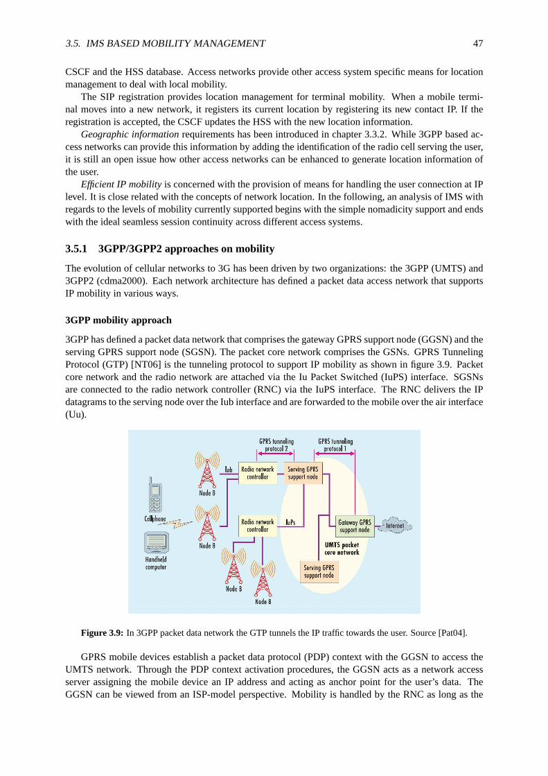
3.5. IMS BASED MOBILITY MANAGEMENT 47
CSCF and the HSS database. Access networks provide other access system specific means for locationmanagement to deal with local mobility.
The SIP registration provides location management for terminal mobility. When amobile termi-nal moves into a new network, it registers its current location by registeringits new contact IP. If theregistration is accepted, the CSCF updates the HSS with the new location information.
Geographic informationrequirements has been introduced in chapter 3.3.2. While 3GPP based ac-cess networks can provide this information by adding the identification of the radio cell serving the user,it is still an open issue how other access networks can be enhanced to generate location information ofthe user.
Efficient IP mobilityis concerned with the provision of means for handling the user connection at IPlevel. It is close related with the concepts of network location. In the following,an analysis of IMS withregards to the levels of mobility currently supported begins with the simple nomadicity support and endswith the ideal seamless session continuity across different access systems.
3.5.1 3GPP/3GPP2 approaches on mobility
The evolution of cellular networks to 3G has been driven by two organizations: the 3GPP (UMTS) and3GPP2 (cdma2000). Each network architecture has defined a packet data access network that supportsIP mobility in various ways.
3GPP mobility approach
3GPP has defined a packet data network that comprises the gateway GPRSsupport node (GGSN) and theserving GPRS support node (SGSN). The packet core network comprises the GSNs. GPRS TunnelingProtocol (GTP) [NT06] is the tunneling protocol to support IP mobility as shown in figure 3.9. Packetcore network and the radio network are attached via the Iu Packet Switched (IuPS) interface. SGSNsare connected to the radio network controller (RNC) via the IuPS interface. The RNC delivers the IPdatagrams to the serving node over the Iub interface and are forwardedto the mobile over the air interface(Uu).
Figure 3.9: In 3GPP packet data network the GTP tunnels the IP traffic towards the user. Source [Pat04].
GPRS mobile devices establish a packet data protocol (PDP) context with theGGSN to access theUMTS network. Through the PDP context activation procedures, the GGSN acts as a network accessserver assigning the mobile device an IP address and acting as anchor point for the user’s data. TheGGSN can be viewed from an ISP-model perspective. Mobility is handled by the RNC as long as the
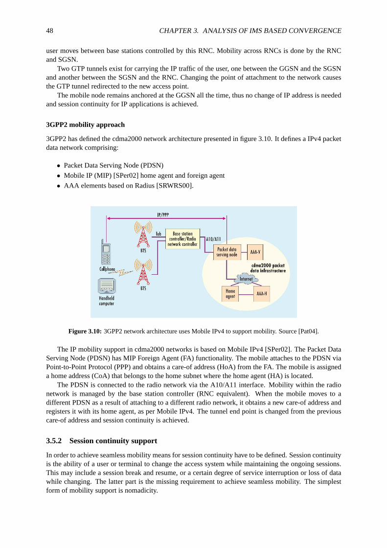
48 CHAPTER 3. ANALYSIS OF IMS BASED CONVERGENCE
user moves between base stations controlled by this RNC. Mobility across RNCs is done by the RNCand SGSN.
Two GTP tunnels exist for carrying the IP traffic of the user, one between the GGSN and the SGSNand another between the SGSN and the RNC. Changing the point of attachment to the network causesthe GTP tunnel redirected to the new access point.
The mobile node remains anchored at the GGSN all the time, thus no change of IP address is neededand session continuity for IP applications is achieved.
3GPP2 mobility approach
3GPP2 has defined the cdma2000 network architecture presented in figure 3.10. It defines a IPv4 packetdata network comprising:
• Packet Data Serving Node (PDSN)
• Mobile IP (MIP) [SPer02] home agent and foreign agent
• AAA elements based on Radius [SRWRS00].
Figure 3.10: 3GPP2 network architecture uses Mobile IPv4 to support mobility. Source [Pat04].
The IP mobility support in cdma2000 networks is based on Mobile IPv4 [SPer02]. The Packet DataServing Node (PDSN) has MIP Foreign Agent (FA) functionality. The mobile attaches to the PDSN viaPoint-to-Point Protocol (PPP) and obtains a care-of address (HoA) from the FA. The mobile is assigneda home address (CoA) that belongs to the home subnet where the home agent (HA) is located.
The PDSN is connected to the radio network via the A10/A11 interface. Mobilitywithin the radionetwork is managed by the base station controller (RNC equivalent). When the mobile moves to adifferent PDSN as a result of attaching to a different radio network, it obtains a new care-of address andregisters it with its home agent, as per Mobile IPv4. The tunnel end point is changed from the previouscare-of address and session continuity is achieved.
3.5.2 Session continuity support
In order to achieve seamless mobility means for session continuity have to be defined. Session continuityis the ability of a user or terminal to change the access system while maintaining theongoing sessions.This may include a session break and resume, or a certain degree of service interruption or loss of datawhile changing. The latter part is the missing requirement to achieve seamless mobility. The simplestform of mobility support is nomadicity.

3.5. IMS BASED MOBILITY MANAGEMENT 49
Nomadicity
The term of nomadic mobility has been defined at the beginning of the chapter and refers to the abilityof the users to change the access system. Nomadicity assumes that users shutdown their service sessionsbefore moving to another access system. There are no session continuity or handover procedures. R7 ofIMS has been defined access independent, thus IMS is well prepared tosupport nomadicity as discussedwithin the FMC requirements analysis in chapter 3.2.6.
The actual nomadicity procedure for IMS due to a change of IP addressis specified in [NT05c]. Itmandates to terminate all established dialogs and transactions and temporarily disconnect the UE fromthe IMS until the new registration is performed. When changing the IP address the UE shall:
1. Terminate all ongoing dialogs (e.g. sessions) and transactions (e.g. subscription to events).
2. Deregister all registered public user identities.
3. Construct a new valid IPv6 address.
4. Register the public user identities that were deregistered in step 2 above,as described in [SA05c]:
(a) Perform an initial registration.
(b) Perform a subscription to the reg event package.
(c) Subscribe to other event packages it was subscribed to before thechange of IPv6 addressprocedure started.
In current IMS release, a change of the IP address affects the degree of continuous service offered tothe end user.
Mobility support within access systems
Session continuity is provided by the access systems with local mobility solutions independent fromIMS (e.g. 3GPP and 3GPP2 mobility approaches presented in chapter 3.5.1). The only requirementsfrom current IMS standards on local mobility solution are:
• Dispose of a local mobility management with handover capabilities (e.g. limited connection inter-ruption and loss of data below certain limits)
• Keep a fixed point in the network at Go interface (e.g. ANG, GGSN, Packet Data Gateway, etc.)
• Keep the IP address stable
Mobility within an access system can include intra-technology (vertical) handovers. How this han-dovers are handled is independent to the IMS as long as the fixed point to the network is kept. Userequipments capable of such handovers should be provided with means to handle the differences betweenthe access technologies, for example by triggering a SIP (re) Invite with SDP adapted to the link capa-bilities of the new access network.
Mobility support between access systems
Changing the access system results in changing the fixed point in the network (serving ANG) and inchanging the IP address of the mobile node. Impacts on current IMS release are that the authenticationof user and authorization of QoS bearers (including charging information) have to be repeated.
Support for session continuity in IMS can be possible with means offered by SIP (e.g. RE-REGISTERto new P-CSCF and sending RE-INVITE to peers). But, service continuitythrough pure SIP mobilitymight be too slow. The degree of service interruption and seamlessness ofthe mobility might not beacceptable for some kind of services.
In addition to this, IMS standards have not yet specified how to deal with theimpacts of these SIPprocedures and additional considerations including charging functions, event subscriptions and othernetwork components and procedures.

50 CHAPTER 3. ANALYSIS OF IMS BASED CONVERGENCE
chapter 4 studies the impacts of inter access system mobility and provides an extensive list of re-quirements and consideration to keep in mind when designing the strategies to handle vertical handoversin NGN IMS based networks. In the following, available solutions to provide seamless connectivity aresurveyed.
3.5.3 Potential solutions for seamless continuity of sessions
Numerous solutions to the seamless mobility problem have been proposed in the literature [TC03,CGZZ04, DOea, EN02, MZ04, TTL99], and these can be classified according to the layer of the OSImodel at which they’re implemented.
Every approach has its own principles, with its pros and cons, but the endgoal is always the same:providing seamless continuity of applications or sessions in dynamic scenarios. Hence, a short survey onhow mobility can be solved at the link, the network, transport or the application layer is presented:
Application layer: Application-layer mobility essentially moves up the managing of the session and theunderlying changes at the IP layer to the application-layer protocol itself.
Rebuilding each applications to support mobility is not a viable solution. But, end-to-end mobilityby means of application layer signaling is a good approach. More than just hand-off support, vari-ous types of mobility allow the provision of flexible services without dependence on the underlyingtransport network.
These are the basics and main advantages of SIP [SW00, PCT03]. The shortcomings come fromthe fact that only SIP based sessions can profit from the mobility support.Though SIP is capableof initiate almost any type of communication sessions, in its current form, support for non-realtime application (e.g. TCP) is not possible [HDS03, Pro02].
Transport layer: UDP and TCP were not designed originally to be applied on wireless networks, thusthey lack on mobility functionality. Consequently, TCP behaves poor in wireless networks since itcannot distinguish between looses due to network congestion or to the radiolink connection. TCPenhancements have been proposed (e.g. M-TCP [BS97], I-TCP [BB94], TCP-Real [ZT01]) butthe required changes in existing equipments are considered prohibitive.
A new transport protocol called Stream Control Transmission Protocol (SCTP) [SSXM+00] pro-vides means to handle the mobility of hosts thanks to its multi-homing capability and dynamicaddress reconfiguration extensions described in the mobile version of theprotocol: M-SCTP[SRT06]. Unlike techniques based on Mobile IP or SIP, the SCTP based mobility scheme doesnot require the addition of components such as home/foreign agents or SIPservers to existing ar-chitectures [XKW02]. Compared with other mobility approaches, SCTP based mobility schemepresents the following advantages:
1. No third party other than the end-points participates in the handover
2. Support concurrent usage of any type of access routers
3. No additional network components or modifications of intermediate routers
In theory, allow seamless handover but the fact that it requires the support of SCTP at both commu-nicating endpoints reduces considerably its applicability. Another disadvantage is that the changeof access network of a user is not transparent to the communicating node.Performance eval-uations are presented in [MYLR04] show the effectiveness of the methodfor seamless verticalhandover between UMTS and WLAN networks. M-SCTP seems to be a solution preferred byservice providers (e.g. multimedia streaming services) to offer mobility-awareservices.
Network layer: The IP layer is the neck of the hourglass design11 of the current protocol stack. There-fore, many solutions at the network layer have been extensively studied and proposed for both
11The concept of hourglass to define the protocol stack appears in the book "Realizing the Information Future: the Internet

3.5. IMS BASED MOBILITY MANAGEMENT 51
local (e.g. HIP, CIP, HAWAII) and global (e.g. Mobile IP) mobility scopes.
Network-layer mobility hides the changes in IP address and network attachments from the upperlayers letting applications essentially unaware of the mobility. Mobility is provided toall applica-tions, rather than dealing with applications individually.
The Mobile IP scheme is the most developed and deployed model today. It basically extends IPby allowing the mobile to effectively utilize two IP addresses, one for identification (permanentIP address or home address) and the other for routing purposes. Homeagent and foreign agentfunctionality keep the location of the mobile up to date and assign and care about proper securityassociations to it. Some drawbacks of Mobile IP include required new entities and host implemen-tation and suffers from triangular routing when not used in optimized mode.
[AXM04] surveys with great detail state of the art for mobility management in next generation IPbased wireless systems, analyzing micro- and macromobility proposed protocols. A good compar-ison of IP mobility protocols can be found in [CGK+02].
Link layer: In this approach, the access technology handles all the mobility so that the IP/network layeris unaware of the users mobility. This is the current approach to deal with mobility in cellularnetworks such as GSM, where the radio access networks handle the mobility between the cell basestations in cooperation with the user device.
Mobility solutions below the IP layer are also referred as tight coupling solutions and achieve highperformance during handovers. But, link-layer mobility solutions for seamless mobility acrossheterogeneous access media are extremely complex. It requires link and physical layer integration(signal interference, interoperability). Current 3G networks use the GTP to handle mobility be-tween GPRS and UMTS networks. It is an 3GPP specific solution and therefore only applicablewhen the mobile device is within the scope of GPRS/UMTS networks.
IEEE 802.11 wireless LANs also provide link-layer mobility. A device moving across 802.11access points within the same distribution system maintains its sessions uninterrupted.
Currently, much effort is being done on the Media Independent Handover standard IEEE 802.21[Soc05] specification promises to ease handovers between the 802.x familyand 3GPP technolo-gies. It provides link layer intelligence and other related network informationto upper layers tooptimize handovers between heterogeneous media (see chapter 4.3.3 for more details on IEEE802.21).
There are many distinct but complementary techniques especially for mobility management to achievehigher performance and scalability during handovers, including [SHS01]:
Buffering and forwarding: to cache packets by the old attachment point during the MN in handoffprocedure, and then forward to the new attachment point after the processing of MN’s handoff.
Movement detection and prediction: to detect and predict the movement of mobile host between dif-ference access points so that the future visited network is able to preparein advance and packetscan be delivered there during handoff.
Handoff control: to adopt different mechanisms for the handoff control, e.g. layer two or layer threetriggered handoff, hard or soft handoff, mobile-controlled or network-controlled handoff.
Paging area: to support continuously reachable with low overhead on location update registration throughlocation registration limited to the paging area.
and Beyond" by theNational Academy of Sciencesand is available at:http://newton.nap.edu/html/rtif/. In the ’hourglass’ modelof the OSA protocol, IP forms the thin waist of the hourglass. Below it, a variety of link protocols have been define, whileabove the waist sita uniform model of transport protocols (e.g. TCP, UDP) and a suite of end-to-end application protocols (e.g.HTTP, FTP, SIP, etc.).
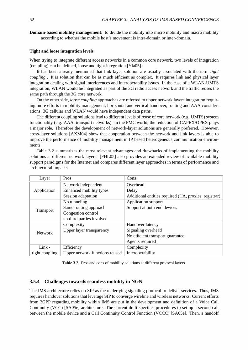
52 CHAPTER 3. ANALYSIS OF IMS BASED CONVERGENCE
Domain-based mobility management:to divide the mobility into micro mobility and macro mobilityaccording to whether the mobile host’s movement is intra-domain or inter-domain.
Tight and loose integration levels
When trying to integrate different access networks in a common core network, two levels of integration(coupling) can be defined, loose and tight integration [Yla05].
It has been already mentioned that link layer solution are usually associatedwith the termtightcoupling . It is solution that can be as much efficient as complex. It requires link andphysical layerintegration dealing with signal interferences and interoperability issues. Inthe case of a WLAN-UMTSintegration, WLAN would be integrated as part of the 3G radio access network and the traffic reuses thesame path through the 3G core network.
On the other side,loose couplingapproaches are referred to upper network layers integration requir-ing more efforts in mobility management, horizontal and vertical handover, routing and AAA consider-ations. 3G cellular and WLAN would have independent data paths.
The different coupling solutions lead to different levels of reuse of core network (e.g. UMTS) systemfunctionality (e.g. AAA, transport networks). In the FMC world, the reduction of CAPEX/OPEX playsa major role. Therefore the development of network-layer solutions are generally preferred. However,cross-layer solutions [AXM04] show that cooperation between the network and link layers is able toimprove the performance of mobility management in IP based heterogeneous communication environ-ments.
Table 3.2 summarizes the most relevant advantages and drawbacks of implementing the mobilitysolutions at different network layers. [FHL05] also provides an extended review of available mobilitysupport paradigms for the Internet and compares different layer approaches in terms of performance andarchitectural impacts.
Layer Pros Cons
ApplicationNetwork independent OverheadEnhanced mobility types DelaySession adaptation Additional entities required (UA, proxies, registrar)
Transport
No tunneling Application supportSame routing approach Support at both end devicesCongestion controlno third parties involved
Network
Complexity Handover latencyUpper layer transparency Signaling overhead
No efficient transport guaranteeAgents required
Link - Efficiency Complexitytight coupling Upper network functions reusedInteroperability
Table 3.2: Pros and cons of mobility solutions at different protocol layers.
3.5.4 Challenges towards seamless mobility in NGN
The IMS architecture relies on SIP as the underlying signaling protocol to deliver services. Thus, IMSrequires handover solutions that leverage SIP to converge wireline andwireless networks. Current effortsfrom 3GPP regarding mobility within IMS are put in the development and definition of a Voice CallContinuity (VCC) [SA05e] architecture. The current draft specifies procedures to set up a second callbetween the mobile device and a Call Continuity Control Function (VCCC) [SA05e]. Then, a handoff

3.6. CONCLUSION 53
between the cellular and IP networks can be triggered. Though, this is an important step towards seamlessmobility across heterogeneous networks, this approach is limited to call services. Further enhancementsare required to extend the service continuity to other services than voice, such as data or multimedia.
With this goal in mind, further work is needed to develop network functions atthe control layer toleverage the converged network with following features and functionalities:
• Effective interworking among different levels (and layers) of MM protocols
• Provision of mechanisms for context transfers at IP layer or above (access system agnostic)
• Provision of a vertical handover management function for seamless service continuity (not onlyvoice services as in VCC)
• Provision of mechanisms for identification of terminals (unique and regardless of access technol-ogy)
The resulting functions should be independent from access network technologies and easy extensibleto emerging technologies. Interworking capabilities with established AAA and security schemes is alsodesired.
3.6 Conclusion
This chapter confirms how IMS greatly facilitates the trend of FMC by eliminating the distinction be-tween wired and wireless networks, though IMS was initially defined for wireless networks. However,the wireline community soon realized the potential of IMS for fixed communication as well. The IMSconcepts, architecture and protocols meet many of the expectations on convergent networks. The adap-tation for wireline requirements seems to be an excellent way to achieve real FMC.
The applicability of IMS to both wireline as well as wireless networks makes is regarded by the ITUfor their NGN. However, some fixed mobile network differences must be accommodated. Features ofmobile devices (e.g. signaling compression) might not be required in bandwidth rich fixed networks.Alternative authentication procedures for subscriber terminals need be defined, since e.g. SIM cards areonly contained in GSM phones. Current dependencies on access networks have to be solved and someenhancements to the user plane access points to the IMS such as service based policies are required.But none of these items seem to be capable of stopping the evolution towards IMS. They are alreadybeing cooperatively addressed by ITU, ETSI, and 3GPP standards bodies to extend the reach of IMS.The entire telecom industry stands to benefit from the FMC paradigm, increasing their products offerand decreasing costs due to shared development of IMS products.
This chapter has also introduced the challenges of mobility management in FMC networks. Themobility management in IMS based systems has been analyzed. Only full support of mobility withincellular 3GPP networks is guaranteed. When adding other access technologies, only the following levelsof mobility support can be provided:
• Nomadicity is provided due to the access independent definition of IMS.
• Mobility within access systems is handled by local mobility solutions.
• Some level of service continuity across different access systems is possible with SIP mobilityconcepts.
But service continuity as supported today in IMS does not fulfill the requirements for seamless mo-bility. SIP mechanisms alone are not enough to maintain session continuity for every type of service (e.g.TCP connections).
It is still an open research issue how to realize seamless handovers between access systems in thecontext of IMS. Mobile IP will play a role (as it does in 3GPP2) but the overall solution is still unclear.The biggest challenge to face is how to keep IP continuity while relocating IMSresource control to thenew access. Context transfers will be required on different levels.

54 CHAPTER 3. ANALYSIS OF IMS BASED CONVERGENCE
As today, there is no straightforward solution that takes account of the multiplicity of mobility man-agement requirements and the heterogeneity of next generation systems. Thus, there is a claim for openinterfaces to IMS such as mobility management services in order to ease the terminal mobility acrossdifferent access systems. Therefore, the next chapter studies the challenges of vertical handovers inIMS based networks in order to consider these issues during the design of a NGN mobility managementscheme.

Chapter 4
Seamless vertical handovers in NGN
A survey across the fixed mobile convergence requirements clearly identifies as a key issue the support ofefficient mobility through different access network. Therefore, inter access system mobility mechanismsneed to be define to ensure seamless vertical handovers in NGN. With theseregards, the challenges ofvertical handovers and the impacts on the IMS need to be studied.
This chapter surveys different approaches and operational strategies looking forward towards a han-dover management function that ensure seamless service continuity. A modeldescribing the differentsteps during a vertical handover in NGN is presented and intends to outline the functional requirementswhen addressing mobility between different access systems in IMS based networks.
4.1 Definitions
In general terms, seamless mobility is an approach that allows users to roam between application domainsand communication networks without being aware of the underlying mechanismsthat enable them to doso. This includes the scenario where a user moves between environments where different networkingcapabilities are present, but the network provides negotiation to allow for seamlessly transparent access.This differs from today’s environment, where handover between heterogeneous networks is not supportedin most cases, and users are required to stop one communication service and initiate another betweendifferent networks.
One definition ofseamless handoverappears in [EN02]:"Ensuring a seamless (or transparent) mi-gration of an element from one domain to another". The major difficulty is how to hide from applicationsany differences between the service during the migration interval and the normal service. Difficulties inseamless handover are also described in the context of the third generation wireless system in [TTL99].Relevant terms and definitions for this chapter include:
Context aware computing: An application design pattern where the application uses knowledge relatedto a set of environment states to determine and change the application behavior [MPW03].
Handover: The process by which a mobile node obtains the preservation of facilities forsupportingtraffic flows upon occurrence of a link-switch event. The mechanisms andprotocol layers involvedin the handover may vary with the type of the link-switch event (e.g. with the typeof the servingand target point of attachment and the respective subnet associations). Different types of handoverare defined based on the way facilities for supporting traffic flows are preserved [Soc05]. The termhandoff has the same meaning and can be used indistinctly.
Seamless Handover:Handover associated with a link switch between heterogeneous interfaces, wherethe mobile node either experiences no degradation in service quality, security, and capabilities,or experiences some degradation in service parameters that is mutually acceptable to the mobilesubscriber and to the network that serves the newly connected interface.
55
56 CHAPTER 4. SEAMLESS VERTICAL HANDOVERS IN NGN
Handover Policies: A set of rules that contribute to shaping the handover decision for a mobile node[Soc05].
Intra-AS handover: A handover where the MN changes its point of attachment inside the same AccessSystem (AS). Such a handover is not necessarily visible outside the AS. In case the ANG servingthe MN changes, this handover is seen outside the AS due to a change in the routing paths (comparewith Intra-AN handover as per [SMK04]).
Inter-AS handover: A handover where the MN moves to a new AS requiring support for macro mo-bility. Note that this would have to involve the assignment of a new IP access address (e.g. a newcare-of address) to the MN (compare with Inter-AN handover as per [SMK04]).
Horizontal handover: This involves MNs moving between access points of the same type (in terms ofcoverage, data rate and mobility), such as, UMTS to UMTS, or WLAN to WLAN. Usually referredas intra-technology handover, a handover between equipment of the same technology [SMK04].
Vertical handover: This involves MNs moving between access points of different type, such as, UMTSto WLAN. Also usually referred as inter-technology handover, a handover between equipment ofdifferent technologies [SMK04].
Note that vertical handovers can happen in intra-AS handovers (e.g. handing over from Bluetooth toWLAN maintaining the fixed access point to the network). The focuss of this work is limited to verticalhandovers during inter access system mobility.
4.2 Challenges and requirements of seamless vertical handovers
Mobility in communication networks is an old problem and faces multiple technical challenges. Seamlessmobility implies a perfect orchestration of mechanisms to deal with the mobility challenges of all-IPnetworks. A problem statement for heterogeneous handover is under IETF work in progress in [SDea05].
Roaming across wireless heterogeneous access systems (e.g. UMTS, 802.11, WiMAX, CDMA) andwired access networks such as cable or DSL is a requirement of NGN morethan an additional feature.Supporting seamless roaming between heterogeneous networks can be very challenging because of thedifferent mobility, QoS and signaling requirements of each access network.
In order to achieve seamless handovers, several issues such as handover metrics and decision algo-rithms, and mobility handling to maintain ongoing user connections, need to be addressed. In the case ofvertical handoff, the following challenges have to be faced:
Criteria: In traditional handovers, the use of the signal strength criterion limits the abilityof the net-work to initiate a handoff for control reason. New criteria and metrics should be considered andevaluated. During a handoff procedure, the metrics upper-layer applications are really interestedin, are network conditions (available bandwidth and delay, user preference, etc.), rather than thephysical layer parameters such as received signal strength and signal-to-interference ratio.
Access system selection:In a heterogeneous environment, more than one access technology couldbeavailable and a decision about the selection of the suitable network to use hasto be taken.
Context: The delivery of the context describing the information flow between the mobilenode and thenetwork becomes more complex. Context information may include information such as secu-rity associations, QoS parameters or authentication information. The transfer of context informa-tion has important benefits e.g. saving of signaling during connectivity establishment and session(re)initiation.
Interoperability: In heterogeneous environments, mobile nodes and network routers must be able to

4.2. CHALLENGES AND REQUIREMENTS OF SEAMLESS VERTICAL HANDOVERS 57
interoperate with different networks. Different QoS and AAA mechanismshave to be accommo-dated.
In addition to this, additional technical challenges and issues from the IMS architectural and func-tional point of view can be identified:
Separation of transport and control planes: While the separation of the SIP signaling path from theuser data path has important efficiency benefits, this feature turns into an additional problem in thecase of handovers. Both paths need to be moved in a seamless way.
IMS (re)registration: Acceding the IMS through a new access network probably implies not only get-ting a new IP address. IMS registration steps have to be repeated and a different P-CSCF will beprobably assigned. Means to reduce the registration time fast registration procedures should beavailable, at least at the service plane (AAA at the access system variesfrom one technology tothe other).
IMS session (re)initiation: Though SIP provides means to support mid-call mobility (sending re-INVITEto the CN), in the actual version of IMS session set up procedures (seechapter 2.5.2) still need tobe repeated. These procedures are very time consuming, therefore means for fast session estab-lishment should be possible.
Charging: A change of access technology usually implies changes in the tariffs for thedata transport.User control over the charging changes is needed. In addition to this, theIMS provider requiresmeans for charging adaptation and continuity when moving through different access networks.
Interoperability when roaming: New network functions (e.g. mobility specific) can not be imple-mented in every visited network (e.g. differences in P-CSCF implementations) causing mobilitymechanisms to fail. The selected schemes should be implemented as much as possiblein the homenetwork an be independent from access systems in order to minimize the requirements on vis-ited networks. Detection of visited networks capabilities and alternative mechanisms for mobilityshould be provided.
Support for IPv4 and IPv6: While the IMS standardization works of 3GPP are based with IPv6 inmind, support for mobility management in IPv4 networks has to be considered. A mobility solutionthat works for both IP versions is desirable.
The analysis on the issues of vertical handovers in general and concretely regarding the IMS architec-ture and functions has pointed out a number of requirements. These and other requirements are summedup in the following section.
Requirements on the vertical handover function
There are many other requirements besides the basic functions that implementthe goal of mobility man-agement in IMS based networks. Additional requirements on performanceand scalability should becarefully taken into account when trying to design a mobility management scheme[SHS01, SKea06a].Requirements for the mobility management in envisioned next generation IMS based networks include:
1. Seamless Handover:The handover mechanisms should minimize the packet loss rate into zero ornear zero which, together with fast handoff. Required operations should be quick enough in orderto ensure that the mobile node can receive IP packets at its new location withina reasonable timeinterval (e.g. fast IMS session (re)establishment, bi-casting during handovers).
2. Signaling traffic overhead: Reduction of signaling overhead in the network and reduction in handover-related signaling volume (e.g. number of signaling packets or accesses to databases) should beminimized.

58 CHAPTER 4. SEAMLESS VERTICAL HANDOVERS IN NGN
3. Efficient use of wireless resources:Since wireless spectrum is a limited and constrained resource,any new signaling or increase existing signaling over the wireless link should be avoided (e.g.increasing packet size by adding tunneling or other per packet overhead, use efficient header com-pression techniques).
4. Support for heterogeneous access technologies:Support for multiple access technologies requiringminimal work to interface with a new link technology. It is required not to use any link specificinformation1.
5. Support for unmodified hosts: To ensure interoperability, new mobility mechanisms should requireminimal special changes on existing components (e.g. mobile node, router, networks, other com-munication nodes, etc.) and should support multiple global mobility management protocols (e.g.SIP, HIP, Mobike, Mobile IPs) for both IPv4 and IPv6 environments.
6. Support of different service types: Support of both real-time and non-real-time multimedia services(both TCP and UDP/RTP based applications). Transparent support ofTCP based applicationsimplies no changes to TCP or TCP-based applications.
7. QoS adaptation: The mobility management scheme should support the establishment of new adaptedQoS reservation in order to deliver a variety of traffic, while minimizing the disruptive effect duringthe establishment and considering the heterogeneous network capabilities.Differences in deviceand network capabilities should be reconciled.
8. Routing efficiency: To achieve QoS guarantees, the routing paths between the communication nodesto the mobile nodes should be optimized after the handover to avoid inefficient routes or redundantpaths (e.g. triangle routing).
9. Fast security: Support different levels of security requirements such as data encryption and user au-thentication, while limiting the traffic and time of security process (e.g. fast security agreements(re)negotiation).
These requirements establish a basis for the design of the mobility management scheme to handlevertical handovers in IMS based network architectures. During the specification and evaluation of themobility mechanisms of the Mobility Management Function in chapter 4.4, references to these require-ments are meant to point out the pros and the cons of the different approaches.
4.3 Mobility management model for NGN
"UE better knows" was true in 2G and 3G, where the horizontal handover was based on thewirelesslink conditions. In NGN networks the wireless link is supposed to be one criteria more in the handoverdecision, since other factors should be taken into account. For example, auser may decide to have aworse video quality on a video stream if he pays less for the service. IMS architecture offers a greatflexibility to deploy a mobility management functionality that generates context information and assiststhe UE and the network during the handover procedures and helps the user in the handover decisions.
For the purposes of this work, the notion of mobility management will be definedas the process ofsequentially performing the following actions:
• Collect information from the UE and access and core network entities to assess the need or oppor-tunity for a handover.
• Choose a handover target, as a result of deciding the next access network and point of attachmentbased on the evaluation of the collected information, QoS needs and other policies.
1Unifying heterogeneous link information and triggers is one of the motivations of IEEE 802.21 Media Independent Han-dover (MIH) [Soc05]. Principles of MIH are later introduced in chapter4.3.3 for basic routing management, though it may beused for other purposes (e.g. mobile node identification).
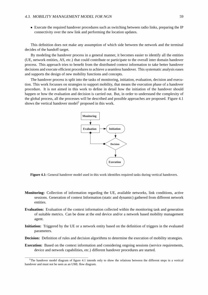
4.3. MOBILITY MANAGEMENT MODEL FOR NGN 59
• Execute the required handover procedures such as switching betweenradio links, preparing the IPconnectivity over the new link and performing the location updates.
This definition does not make any assumption of which side between the network and the terminaldecides of the handoff target.
By modeling the handover process in a general manner, it becomes easierto identify all the entities(UE, network entities, AS, etc.) that could contribute or participate to the overall inter domain handoverprocess. This approach tries to benefit from the distributed context information to take better handoverdecisions and execute efficient procedures to achieve a seamless handover. This systematic analysis easesand supports the design of new mobility functions and concepts.
The handover process is split into the tasks of monitoring, initiation, evaluation, decision and execu-tion. This work focusses on strategies to support mobility, that means the execution phase of a handoverprocedure. It is not aimed in this work to define in detail how the initiation of the handover shouldhappen or how the evaluation and decision is carried out. But, in order to understand the complexity ofthe global process, all the processes will be described and possible approaches are proposed. Figure 4.1shows the vertical handover model2 proposed in this work.
Initiation
Decision
Execution
Monitoring
Evaluation
Figure 4.1: General handover model used in this work identifies requiredtasks during vertical handovers.
Monitoring: Collection of information regarding the UE, available networks, link conditions, activesessions. Generation of context Information (static and dynamic) gathered from different networkentities.
Evaluation: Evaluation of the context information collected within the monitoring task and generationof suitable metrics. Can be done at the end device and/or a network based mobility managementagent.
Initiation: Triggered by the UE or a network entity based on the definition of triggers in the evaluatedparameters.
Decision: Definition of rules and decision algorithms to determine the execution of mobility strategies.
Execution: Based on the context information and considering ongoing sessions (service requirements,device and network capabilities, etc.) different handover proceduresare started.
2The handover model diagram of figure 4.1 intends only to show the relations between the different steps in a verticalhandover and must not be seen as an UML flow diagram.
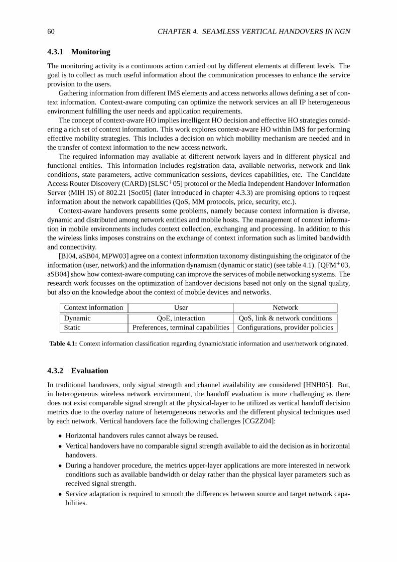
60 CHAPTER 4. SEAMLESS VERTICAL HANDOVERS IN NGN
4.3.1 Monitoring
The monitoring activity is a continuous action carried out by different elements at different levels. Thegoal is to collect as much useful information about the communication processes to enhance the serviceprovision to the users.
Gathering information from different IMS elements and access networks allows defining a set of con-text information. Context-aware computing can optimize the network services an all IP heterogeneousenvironment fulfilling the user needs and application requirements.
The concept of context-aware HO implies intelligent HO decision and effective HO strategies consid-ering a rich set of context information. This work explores context-aware HO within IMS for performingeffective mobility strategies. This includes a decision on which mobility mechanismare needed and inthe transfer of context information to the new access network.
The required information may available at different network layers and in different physical andfunctional entities. This information includes registration data, available networks, network and linkconditions, state parameters, active communication sessions, devices capabilities, etc. The CandidateAccess Router Discovery (CARD) [SLSC+05] protocol or the Media Independent Handover InformationServer (MIH IS) of 802.21 [Soc05] (later introduced in chapter 4.3.3) are promising options to requestinformation about the network capabilities (QoS, MM protocols, price, security, etc.).
Context-aware handovers presents some problems, namely because context information is diverse,dynamic and distributed among network entities and mobile hosts. The managementof context informa-tion in mobile environments includes context collection, exchanging and processing. In addition to thisthe wireless links imposes constrains on the exchange of context informationsuch as limited bandwidthand connectivity.
[BI04, aSB04, MPW03] agree on a context information taxonomy distinguishing the originator of theinformation (user, network) and the information dynamism (dynamic or static) (see table 4.1). [QFM+03,aSB04] show how context-aware computing can improve the services of mobile networking systems. Theresearch work focusses on the optimization of handover decisions based not only on the signal quality,but also on the knowledge about the context of mobile devices and networks.
Context information User Network
Dynamic QoE, interaction QoS, link & network conditionsStatic Preferences, terminal capabilitiesConfigurations, provider policies
Table 4.1: Context information classification regarding dynamic/static information and user/network originated.
4.3.2 Evaluation
In traditional handovers, only signal strength and channel availability are considered [HNH05]. But,in heterogeneous wireless network environment, the handoff evaluation ismore challenging as theredoes not exist comparable signal strength at the physical-layer to be utilized as vertical handoff decisionmetrics due to the overlay nature of heterogeneous networks and the different physical techniques usedby each network. Vertical handovers face the following challenges [CGZZ04]:
• Horizontal handovers rules cannot always be reused.
• Vertical handovers have no comparable signal strength available to aid thedecision as in horizontalhandovers.
• During a handover procedure, the metrics upper-layer applications aremore interested in networkconditions such as available bandwidth or delay rather than the physical layer parameters such asreceived signal strength.
• Service adaptation is required to smooth the differences between source and target network capa-bilities.
4.3. MOBILITY MANAGEMENT MODEL FOR NGN 61
Inter-system mobility means the ability to switch between access technologies during sessions. Somereasons for inter-system mobility are:
• Throughput
• Price
• Load balancing
• Service quality support
The complexity of heterogeneous networks opens the question of what factors should be considered inthe handoff decision. Therefore, after considering the main players ofthe problem, the most importantdecision factors were identified. The envisioned IMS based system should consider following proposedmetrics [MZ04, HNH05]:
• Service description: Includes information about service types and costs. Combinations of reli-ability, latency, and data rate in addition to different billing/charging strategiesaffect the user’schoice of handoff
• Quality of Service:
– Network conditions: Traffic, available bandwidth, network latency, congestion, packet loss,etc.
– Link performance/conditions: Channel propagation characteristics such as path loss, inter-channel interference, signal-to-noise ratio, bit error rate, etc.
– Quality Of Experience (QoE): User perception of the quality of the service is variable andshould be adjustable.
• Mobile node conditions: Power requirements, velocity, moving pattern and histories, locationinformation, etc.
• User preferences/interaction:Can be used to cater to special requests for one type of system overanother.
• Security: Risks of wireless technology, security associations, AAA capabilities, etc.
Theservice descriptionusually includes a complete description of the required media (codecs, band-width, delay, max. packet loses) and is associated with aservice cost. The cost of the different services tothe user is a major issue, and could sometimes be the decisive factor in the choice of a network. Differentservice providers may provide a variety of billing options that will probably influence the customer’schoice of network and thus the handover decision.
Quality of Servicedeals with the provision of improved service levels. A handover to a networkwithbetter conditions and higher performance would usually improve the QoS. Transmission and error rates,link and network conditions and other characteristics can be measured in order to decide which networkcan provide a higher assurance of continuous connectivity.Quality Of Experience (QoE)is concernedQoS perceived by the final user and may vary depending of the context.For example, one user mayconsider acceptable a low quality streaming service while another user may require better quality for thisservice and is willing to pay the quality difference. Therefore,user preferencesshould be always takinginto account and user’s interaction capabilities during a handover decision should be provided.
Information aboutmobile node conditionsshould be part of the decision strategy. For instance, ifa device’s battery level is critical handing off to a network with low power consumption can increasethe usage time (e.g. WLAN to WWAN would be a smart decision regarding batteryconsumption). Invertical handovers, the velocity factor has an imperative effect in handovers decision than in traditionalhorizontal handovers. Because of the overlaid architecture of heterogeneous networks, a handover to anetwork with small coverage when moving at high speeds is discouraged. Ahandoff back to the originalnetwork would occur very shortly afterwards. This effect of constantly handing over is called the "ping-pong" effect and can be avoided by managing the moving patterns and histories or acceding to locationinformation of the available networks.

62 CHAPTER 4. SEAMLESS VERTICAL HANDOVERS IN NGN
Finally, securitythreats are inherent in any wireless technology since the technology’s underlyingcommunications medium, the airwave, is open to intruders. Therefore, security should be chosen as oneof the main factors for vertical handoff decisions.
4.3.3 Initiation
The initiation is the process recognizing the potential need for a handover and subsequently initiating it.The initiation of the handover procedures can be triggered at differentplanes:
• User plane:
– UE: Radio link conditions, battery status
– User preferences: Perceived QoS, user interaction, subscription profiles, security require-ments, etc.
• Network plane: Network load (terminating), connectivity lost (P-CSCF initiated)
• Service plane:New service requirements (e.g. security, QoS)
Many different triggers can be defined at the different planes. At theend the result has to be the same,to sign the potential necessity of a handover to the entity handling the user’s mobility. The initiationcriteria very simple. A handover may be required when the battery life of the UE drops below a certainthreshold. Then, in the next step an evaluation engine should decide whichaccess network can be selectedto optimize the battery life.
But, the initiation algorithm can be very complex if it tries to process many parameters and decidewhether a handover to another system may be required. Additional techniques are required to computethe input parameters.
[MYP00, MK02, CSHe01] have studied how to applyfuzzy logicto the handover process. A fuzzylogic algorithm is separated into three different stages. In the first stage,data from the system is convertedinto fuzzy sets. A fuzzy set is a set without a clearly defined boundary and are defined by a degree ofmembership to the set. The system data can be formed by values defining perceived QoS, networkcoverage, bit error rate and average signal strength measurements which are mapped into a membershipvalue of a fuzzy set.
In the second stage, a set of IF-THEN fuzzy rules is applied to the system.Fuzzy rules are conditionalstatements that specify how the fuzzy system is intended to work. The examplein listing 4.1 illustratesthis concept:
1
IF signal strength is strong, AND QoS is good, AND Bit Error Rate is medium,3 AND Network Coverage is medium, THEN handover = NO
5 IF signal strength is poor, AND QoS is medium, AND Bit Error Rate is medium,AND Network Coverage is strong, THEN handover = Possibly YES
Listing 4.1: Fuzzy rules define handover initiation triggers
The possible outcomes have been defined to be: Yes, Possibly Yes, and Possibly No. A table isgenerated that shows the outcomes for all possible values of the input criteria. The final step is thedefuzzification process, where all outputs are aggregated to producea single number that represents thehandover factor. This final handover factor determines if the handover should be initiated or not.
[MP01, MYP00] have proposed inter technology handover algorithms usingneuronal networksbasedpattern classification. In [MYP00] signal strength measurements are usedfor path identification. Then,as a user moves away from a WLAN access point, the system recognizes the migration path from trainedsamples and therefore knows the most optimal handover initiation time. Drawback is that type of han-dover initiation algorithm requires prior knowledge of the radio environmentso that the neural networkscan be trained before system deployment. The author’s argue, however, that this training can be con-ducted gradually by such calledonline training.
4.3. MOBILITY MANAGEMENT MODEL FOR NGN 63
Inputs likesignal strengthare difficult to be compared in heterogenous systems, thus the evaluationtask should accommodate heterogenous information and provide comparablemetrics. Following thisconvergence philosophy started the work of IEEE 802.21
Principles of IEEE 802.21 Media Independent Handover (MIH)
The work in progress of IEEE 802.21 Media Independent Handover (MIH) [Soc05] provides link layerintelligence and other related network information to upper layers to optimize handovers between het-erogeneous media.
The (MIH) function is a shim layer within the mobility-management protocol stackof both the mo-bile node and network elements. It is designed to enable handovers associated with heterogeneouslink switching. The MIH function provides services to the upper layers through a single technology-independent interface and obtains services from the lower layers through a variety of technology-dependentinterfaces or Service Access Points (SAPs)[Soc05].
Standard draft version 3 of IEEE 802.21 defines a MIH architecture currently covering 802.03,802.11, 802.16 and 3GPP/3GPP2 SAPs and their primitives. MIH principles and design assumptionsprovide:
• Supported media independent services can help with network discovery and network selectionleading to more effective handover decisions
• List of available networks (802.11, 802.16, 3GPP)
• Link layer information (e.g. neighbor network graphs)
• Higher layer services (IMS, VPN, ISP services, etc.)
• Link layer intelligence (events based on trigger) to improve device mobility in multi-radio envi-ronment.
MIH is designed for existing and evolving networks and does not modify existing handover princi-ples. No redesign of existing PHY/MAC nor new mobility protocols are defined. 802.21 stacks betweenlayer 2 and layer 3 as shown in figure 4.2. MIH does not handle handover execution nor mandateshandover determination based on events. The events offered by MIH are informational in nature.
802.21 will play a major role in the development of FMC because of the "technology melting" natureof this media independent protocol. [DOea] presents an experimental testbed implementation and perfor-mance results confirming that 802.21 can reduce disconnection times and packet loss during handovers.Figure 4.3 shows a snapshot that illustrates how SIP based handovers can be optimized with 802.21.
The monitoring process defined in this work can greatly benefit from the information provided bythe services of MIH. [Gup] describes a generalized model for link layertriggers in 802 based networks.These proposed triggers and the proposed trigger may form the basis for a generalized trigger serviceto be defined in 802.21. Key L2 triggers that can be used in the handover process across heterogeneousnetworks are for exampleLink_Up, Link_Down, Link_Quality_Crosses_Threshold, Link_Going_Downor Better_Signal_Quality_AP_Available. Such MIH triggers or other type of events trigger the evaluationprocess that decides whether a handover should happen and how.
4.3.4 Decision
One of the chief issues that aid in providing seamless handoff is the ability to correctly decide whichand whether or not to carry out vertical handoff at any given time. Thedecision engine is triggered bythe initiation routine. While the trigger to initiate a handover may come from many different entities,the decision engine should be located at one point (network or UE). But the input parameters can bedistributed among different locations. Although the reason for a handover initiation may be sufficientduring the decision phase to start the handover, other factors may be considered by the decision engine.In addition to this, a decision algorithm should decide to which of the available networks handoff. So themain tasks to be accomplished are:

64 CHAPTER 4. SEAMLESS VERTICAL HANDOVERS IN NGN
Figure 4.2: IEEE 802.21 Media Independent Handover function as a shim layer within the mobility managementprotocol [Soc05].
1. Handover decision:Compute the handover initiation request with additional available metrics.
2. Network selection:Decide the target available network for the handover.
The evaluation criteria described before, tries to provide suitable metrics for the decision engine. Inmulti-network environments, the decision function is very challenging and hard to achieve as there doesnot exist a single factor than can provide a clear idea of when to handoff.
The handoff decision should be service aware and it should be possibleto move only some of theongoing sessions to another network. For billing reasons one available network may have preference butit does not assure the QoS that are currently guaranteed in the actual network. The solution is often func-tion of many variables, some of them could be sometimes not available. This is further complicated bythe fact that different wireless access technologies offer differentdynamic QoS parameters such as avail-able access bandwidth and access delay, which could be difficult to obtain. [BI04] proposes a handoverdecision making process which uses context information regarding user devices, user location, networkenvironment and requested QoS. In the following, several approaches with examples and references forrelated work are presented.
Rules based decision
One approach is the definition of rules inter system mobility. This technique is also referred to as policybased networking. Policies are rules that govern the choices and behavior of a system. Considerableamount of work is being done to use policies to provide NGN with flexible and highly adaptive capabil-ities [VCP04].
The rules decide whether handover is necessary and to which network by answering questions suchas: "When to change from access technology A to access technology B? When does one switch back fromaccess technology B to access technology A?". One scenario could consider all services are required touse the same access technology. But it is reasonable to consider the optionthat some services use A,others B. The following examples show how simple rules for inter-system handovers can be defined:

4.3. MOBILITY MANAGEMENT MODEL FOR NGN 65
Figure 4.3: Optimized SIP based mobility assisted by 802.21 by reducingthe disconnection time [DOea].
Case 1: Only one access technology can be activated at a time. Assume higher bandwidth and cheaperprice for WLAN access, but no service quality support for streaming.
1
If (using data services AND using GPRS AND WLAN hotspot available) then ←֓
Begin3 If NOT (streaming sessions active) then
handover(GPRS, WLAN)5 End
Listing 4.2: Rule-based decision algorithm where only one access technology can be activated at a time
Case 2: WLAN and GPRS can be simultaneously active. WLAN assumed to be cheaperand to havehigher throughput. No streaming service quality support in WLAN assumed.Decision as towhether to handover data session X from GPRS to WLAN.
1
If (using data services AND data session X using GPRS AND WLAN hotspot ←֓
available) then3 handover(GPRS, WLAN, session X)
Listing 4.3: Rule-based decision algorithm where WLAN and GPRS can be simultaneously active
It has been shown during the initiation phase how the definition of rules serves establish a decisionmechanism. Therefore, in the case of network selection, fuzzy logic couldbe used to determine thebest available network for the handover [Yla05]. [MMP03] presents afuzzy logic based inter-systemhandover initiation algorithm. The algorithm decides the time to initiate a handover request to anotheravailable access network based on QoS and pricing tariffs.
VHO Decision Function
This approach suggests the use of a mathematical expression to evaluate theneed of vertical handoverdepending on the input variables. The function can be applied to measure the goodness of a networkor to express the requirements of a service. The decision function can take many forms and have manydifferent input types and parameter weights.
One example is presented in [HNH05], the authors describe avertical handover decision functionthatevaluates the metrics and assists the handover process. A so called network quality (Q) factor provides ameasure of the usability and appropriateness of a certain network measured via a function that pondersthe listed metrics and factors:
Q = f(0.4aC, 0.1bW, 0.05cS, 0dU, 0.2eN, 0.1fP, 0.05gV ) (4.1)
66 CHAPTER 4. SEAMLESS VERTICAL HANDOVERS IN NGN
In equation 4.1a,b,c,d,e,f and gare coefficients to adapt the heterogenous units of the factors. wouldmean that the overall value of the network, relevant to vertical handoff,is heavily dependent on themonetary cost (C) of the network. Security (S) and velocity (V) in this case have a small effect onthe decision and user preference (U) is not considered at all. The weighting factors (a-g) show thepriority ratios between the different characteristics; for instance monetary cost is twice as important asnetwork (N) conditions and quadruple times more imperative than power (P) requirements and networkperformance (W). Considering ongoing services, a value can be calculated for each available accessnetwork e.g. AN1, AN2, etc.:
AN1 = S1 ∗ ((C11 ∗ P1 + C2 ∗ P2) ∗ Service1 + (C31 ∗ P3 + . . .) ∗ Service2 + . . .) (4.2)
AN2 = S2 ∗ ((C12 ∗ P1 + C2 ∗ P2) ∗ Service1 + (C32 ∗ P3 + . . .) ∗ Service2 + . . .) (4.3)
Self-learning Strategies
Note that the presented decision algorithms are not exclusive. A mixed approach would firstly define arule based decision process and whenever an unknown situation occurs a decision function takes careof it. This model could also work in conjunction with a self-learning strategy. An intelligent algorithmcould learn from the users feedback and consider the users handover preferences for future handoffdecisions. One approach could be based on neuronal networks similar tothe principles presented in[MP01, MYP00] for handover triggers.
The selection and decision process could take place at the network or mobile node and must appro-priately adjust the constraints (e.g. authorization, billing). It should be the user who hast the final controlon the handover process, either defining his standard preferences or through his interaction.
4.3.5 Execution
Once the vertical handoff decision has been made, the next step for a roaming system is how to maintainconnection and service continuity after a vertical handoff.
There is much work being done at the physical and network level to execute handovers at the connec-tivity access network. But mobility management in real world deployments requires implementations atdifferent layers. As outlined in [oGMCT00], handover execution across heterogeneous networks facesfollowing challenges:
1. Connection Changes: Changing radio links often means changing radio access nodes. Newconnections need to be set up and superfluous connections released.
2. Switching and bridging: If data is to be transmitted on two connections (packet duplication) orif data coming on two connections is to be combined on one connection, a bridgeconnection isrequired. Bridge connections are used, for instance, to prevent lossof data. Once this feature is nolonger needed the bridge is released.
3. Combining and multicasting: In the case where macro diversity is supported by the layer networkinvolved, connections are added to and released from multi-casting and combining points. In thiscase, adding a connection does not imply releasing another.
4. Re-routing: Handover may imply re-routing of connections through the fixed network, even out-side the access network that is currently involved.
5. Control point transfer: If a user moves from one domain to another, it could be required totransfer control.
6. Security functions: Handover often requires the transfer of security keys and authentication.
To overcome these issues, upper layer context transfers have been already identified in chapter 3.5.4as a required feature of NGN.

4.3. MOBILITY MANAGEMENT MODEL FOR NGN 67
Context Transfers
Context transfer is designed to allow communication entities to exchange useful information. This in-formation is referred as state or context information and may consist of user/service preferences andtechnical parameters, such as access delay, available bandwidth, and capabilities of the terminal.
In the absence of context transfer there may be large delays. The network signaling required to re-establish QoS flows, re-authentication the mobile user at the new access point, set the header compressionalgorithms, etc. [SKem02] explains the main reasons why context transfer procedures may be useful inIP networks.
• Mobile Nodes establish network state at their ANG (AAA like IPSec or charging information,QoS, Header compression, etc.)
• State needs to be re-established in the new access network
• Context transfer during handovers:
– saves signaling overhead over the air interface
– provides performance benefits for transport protocols
– helps to make handovers seamless
Horizontal context transfer already happens among in the access network at the link layer (e.g.IEEE 802.11F). The transfer of context information during vertical handovers presents some difficul-ties [MZ04, MPW03].
Context information characteristics: It is difficult to collected the high amount of dynamic and dis-tributed context information. For a handover between different networks, some context infor-mation is not relevant or missing. To compile the relevant context information effectively, datastructures as in chapter 4.4.4 have to be carefully defined.
Performance: If the context transfer delay is too large the advantages of context transfer have beenremoved.
Quality of service (re)negotiation: In VHO there may be a change in service quality (differences inbandwidth availability, congestion, interference). Means for session adaption may be required.
Inter-operability: Context transfer messages must be specified and formatted so as to be interpretableby the target network. Different access systems may not be able to use some context information(e.g. different QoS parameters).
To overcome these difficulties a common efficient context transfer protocol needs to be implementedin the ANG and the S- and P-MMF. Context transfers below the network layer are not new. They arespecifically defined for each access technology (e.g. between AP in WLAN or between base stations incellular networks). In heterogeneous environments, the transfer of contexts should be considered at IPlayer or higher. Therefore, two alternatives are suggested:
1. Use SIP to transport the context information in the message body.
2. The Context Transfer Protocol (CXTP) [SLNPK05].
SIP and XML for context information transport: Re-using the signaling protocol of IMS is the mainadvantage of using SIP to transfer context information. The IMS SIP addressing can be re-used as wellas the deployment experience on SIP communications. SIP methods like MESSAGE or SUBSCRIBE-NOTIFY can carry application information in their message bodies. A value definition for theContent-Typeheader such as "application/contextinfo+xml" would be required. Furtherwork would be requiredon the specification of the operations of the context transfers flows and itscontext data representation.
XML has been proofed to be good technology to represent information in SIP communications (NO-TIFY body). A simple example of context information representation is shownin figure 4.4.

68 CHAPTER 4. SEAMLESS VERTICAL HANDOVERS IN NGN
1 <?xml version="1.0"?><mmfinfo xmlns="urn:ietf:params:xml:ns:reginfo" version="0" state="full">
3 <registration aor="sip:[email protected]" id="as9" state="active"><contact id="76" state="active" event="registered">
5 <uri>sip:[5555::aaa:bbb:ccc:ddd]</uri><unknown-param name="audio"/>
7 <an-info><an-info/>
9 </contact><session id="76" state="active">
11 <contact-id>sip:[5555::aaa:bbb:ccc:ddd]</contact-id><sdp><sdp/>
13 <p-mmf>< p-mmf/></ session >
15 </registration></mmfinfo>
Listing 4.4: Data representation of context information in XML
Context Transfer Protocol (CXTP): The Seamoby (Context Transfer, Handoff Candidate Discov-ery, and Dormant Mode Host Alerting) IETF working group [SIET05] recently (July 2005) concludedtheir work with the publishing of the experimental Context Transfer Protocol (CXTP) [SLNPK05]. Theprotocol is designed to work in conjunction with other protocols in order to provide seamless mobilitywith supports to both IPv4 and IPv6. Chapter 3.5.4 already anticipated the need for for context transferscapabilities at IP layer. CTXP seems to be a good candidate and defines means for:
• Representation for feature contexts.
• Messages to initiate and authorize context transfer, and notify a mobile nodeof the status of thetransfer.
• Messages for transferring contexts prior to, during and after handovers.
CXTP proposes support for several scenarios of context transfers. signaling flows are presented fornetwork and mobile controlled transfers. The initiator of transfers in the network can be the previous(predictive) access router or the new (reactive) access router.
The message types used in this protocol are:
• Context Transfer Request (CT-Req) Message
• Context Transfer Activate Request (CTAR) Message
• Context Transfer Activate Acknowledge (CTAA) Message
• Context Transfer Data (CTD) Message
• Context Transfer Data Reply (CTDR) Message
Figure 4.4 shows an example of the use of CXTP. After a context transfer(CT) trigger, the UE sendsa request (CTAR) for context transfer to the new access router (nAR). The nAR sends a CT request (CT-Req) message containing the type of context information is required. The context information is carriedin the CTD message from the previous access router (pAR). Acknowledgements to the context transfermessages can be optionally sent (CTAA to MN and CTDR to pAR).

4.3. MOBILITY MANAGEMENT MODEL FOR NGN 69
UE new AR ( old CoA )
old AR ( new CoA )
CTAR
CT trigger
CT Req.
CTD
CTDR ( opt.) CTAA
Figure 4.4: Network controlled CXTP [SLNPK05] flow example initiated bynew access router.

70 CHAPTER 4. SEAMLESS VERTICAL HANDOVERS IN NGN
4.4 Mobility Management Function (MMF)
Seamless mobility in IMS based networks has been identified as an issue requiring further work andenhancements to the actual NGN architectures. A vertical handover management function for seamlessservice continuity has been claimed regardless of the access technology used. After the identification ofthe challenges of vertical handovers in NGN networks, this work intends toaddress some of the issues byproposing mechanisms and strategies to provide a framework for delivering seamless service continuity.
Pure IP-level connectivity transfer may not suffice to provide seamlesshandoff experience to enduser in many cases. It is the lack of knowledge of the application semantic at IP level that preventsseamless continuation of the session. Hence, there is a need for additionalmechanisms, which can takeinto account application semantic and perform relocation of application-specific functionality at the timeof handoff.
A Mobility Management Function (MMF) for IMS is designed with the goal of easing user’s mo-bility across heterogeneous access systems. By using information gathered from the network, the MMFcombines this information and decides about the execution of mobility mechanisms toprovide seamlessservice continuity over the new access network. The surveys on different mobility mechanisms and cur-rent standardization work in progress is a step forward on the way to the ABC concept [GJ03] envisionedfor NGN. Before introducing the functionality of the MMF, relevant terms and the reference architectureare presented.
4.4.1 Terms and definitions
Hard handover: Handover where facilities for supporting traffic flows are subject to complete unavail-ability between their disruption on the serving link and their restoration on the target link (break-before-make) [Soc05].
Soft handover: Handover where facilities for supporting traffic flows are continuously available whilethe mobile-node link-layer connection transfers from the serving point ofattachment to the targetpoint of attachment. The network allocates transport facilities to the target point of attachmentprior to the occurrence of the link-switch event (make-before-break)[Soc05].
Terminology consensus
Terminology used in the literature and industry are usually subject to different interpretations and aconsensus should avoid confusions to the reader. At this point, it is veryimportant to understand thedistinct terms that refer to network elements that are functionally comparable tothe definition of theAccess Network Gateway (ANG) used in this work.
The actual IMS release of 3GPP has been done access type independent, thus everything "below" theIMS entry point is defined as IP-CAN [SA05c]. IP-CAN and the term "access system" refer to the sameconcept and are used indistinctly in this work. An example of an IP-CAN or an access system is GPRSand is based on UTRAN/GERAN as the AN (radio AN in this case) and the GGSNacting as the ANG.
For the purposes of mobility a consistent definition of the network entity at the edge point of theaccess system is required. The name of Access Network Gateway (ANG)is an attempt to generalize thedifferent terms found in related work and achieve some level of consensus about the pretended function-ality. A definition of an access network gateway appears in [SMK04]:
Access Network Gateways (ANG):An Access Network Router that separates an Access Network fromother IP networks, much in the same way as an ordinary gateway router. The Access NetworkGateway looks to the other IP networks like a standard IP router. In a small network, an ANG mayalso offer the services of an access router (AR), namely offer the IP connectivity to the mobilenodes.

4.4. MOBILITY MANAGEMENT FUNCTION (MMF) 71
In other IETF RFCs terms likeAggregation Routeror Access Network Edge Pointare used dependingon the scope of the document.
The industry prefers terms like Border Gateways (BG) or Session Border Controller (SBC). There islittle use of these terms in RFCs or 3GPP standards. SBC can be regarded asthe final implementation (orcommercial product) of an ANG, but usually SBCs lack of IP connectivity enabling functions (e.g. IPassignment). SBC are commonly deployed to fill the missing security (e.g. firewall) and interconnection(e.g. QoS and signaling adaptation) capabilities os edge routers. [Cum05] describes very good thedifferent views and the varied roles that SBCs play in IMS.
3GPP System Architecture Evolution (SAE) documents refer to this network entity as an AccessSystem Gateway (ASGW) and can be confused with the term User Plane Entity(UPE)[Evo06]. UPEdescribes in a generic manner the network entity carrying the responsibility for delivering the IP trafficto the UE. A Packet Data Serving Node (PDSN) is the access gateway between the CDMA radio networkand the core packet network specified by 3GPP2. ETSI TISPAN names such network element AccessBorder Gateway Function (A-BGF) as part of the Network Attachment Subsystem (NASS). Finally,depending on the access technology, examples of ANG are:
• GGSN in GPRS networks
• B-RAS in xDSL access networks
• PDSN in CDMA networks
• ASN GW (Access Service Network GateWay) in WiMAX networks
• Packet Data Gateway (PDG) in WLAN access networks.
For the sake of simplicity and following the convergent trend of NGN, only theterm of ANG willbe used in this work. It is not important the name this network entity but the understanding of itsfunctionality.
4.4.2 Reference architecture
The protocols and entities described in this document can be used to handle IP mobility within an IMSProvider Domain (IPD) . The reference network architecture is shown infigure 4.5. A single IPD spans awhole administrative domain such as the network of an operator. The edge of the IPD is made of AccessNetwork Gateways (ANG), Border Gateways (BGs) and Media Gateways(MGW). The core network iscontrolled by the IMS. The MMF described in this work is defined as part ofthe IMS but MMF functionscan be required in other elements of the IPD. The domain up to the entry point to the IMS is referred asthe IP-CAN.
ANGs manage IP links offering connectivity to Access Networks (AN) such as WLAN or RadioAccess Networks (RAN) like UTRAN/GERAN, each one univocally associated with at least an IPv6prefix. The concept of the ANG represents an entity that unifies the terminology and functionality of thenetwork elements that provide IP connectivity. Further discussion on terms, functions and requirementsof the ANG are presented in chapter 4.4.2. ANG provide the access to the IMS by delivering the IMScommunications to the entry point of the IMS, namely the P-CSCF.
A border gateway (BG) is defined to interconnect the IPD with external networks such as other IPDsor traditional IP networks like the Internet. Though, IP communications to external networks could flowdirectly from the ANG, for technical reasons (IP transport efficiency, security, etc.) it can be desired toanchor the external data flows through a BG.
The MGW handles the communications between IP and circuit switched (CS) networks enablinginterworking with the PSTN as defined explained in chapter 2.3.
The internal topology of an IPD and transport technologies interconnecting the network entities re-main intentionally undefined and do not affect the proposed protocols. Out of the scope of this work arethe definition of the access network (AN) related entities, since their primitivesand functions differ fromone access technology to the other.

72 CHAPTER 4. SEAMLESS VERTICAL HANDOVERS IN NGN
IP - CAN
AN ( e.g. xDSL )
UE
BG
ANG ( e.g. B- RAS )
ANG ( e.g. PDG )
ANG ( e.g. GGSN )
IMS MGW PSTN
external NETWORK ( e.g internet )
P P P
CSCF MMF
IPD
AN ( e.g. UTRAN / GERAN )
UE AN
( e.g. WLAN )
UE
Figure 4.5: Reference architecture describing the IMS Provider Domainused in this work.
Assumptions
• The edge points of the network (ANG, BG, MGW) share security associations.
• Each ANG provides the required interfaces and reference points to communicate with the ANrelated entities (base stations, access routers, etc.) and with the P-MMF.
• No roaming considerations between IPDs are discussed at this point3. Therefore no network hidingconfiguration is needed and the I-CSCF is left out of the signaling flows.
• Assumptions and consideration of the user terminal are described in chapter 4.4.2.
• Overlapping of radio coverage zones ensure simultaneous connectivityduring handovers.
• In most of the flow diagrams the communicating partner of the moving user is another UE, butpresented concepts apply also to other SIP capable entities (e.g. applicationservers).
User Equipment (UE)
The simplified model assumes that each air interface interworks with only one IP address (no multi-homing capabilities as explained in chapter 4.4.7). Figure 4.6 illustrates the representation of the userequipment in this work.
The split of UE intoUEa andUEb is motivated by the fact that terminal mobility across heteroge-neous networks (vertical handovers) can be regarded as a sessionmobility from oneIPa to IPb. Althoughthe definition of session mobility implies a change of terminals, a certain parallelism between verticalhandovers and session mobility can be drawn. Both mobilities imply a change of access technology andtype of access point to the network (different ANG). Either case of mobilityface almost the same chal-lenges when looking to achieve service continuity. Thus, concepts and mechanisms can be shared. Themain differences are in the requirements of the session handover, since session mobility is more relaxedin terms of duration of the handover and jitter. The requirements on the middleware and application layerimplementations in case of moving the session from one device to another differfrom the capabilitiesrequired from a multi-interface device. These differences and how to implement the required functionsare clearly out of the scope of this work.
It is assumed that the SIP UA in the UE can correctly handle multiple registrationsand IP addresses.Further required functionalities of the UE are also assumed (multi-interface network detection, protocol
3The research on interconnection of IPDs is placed for future work, though concepts worked out in this work are expectedto be easily applied and extended with these regards.
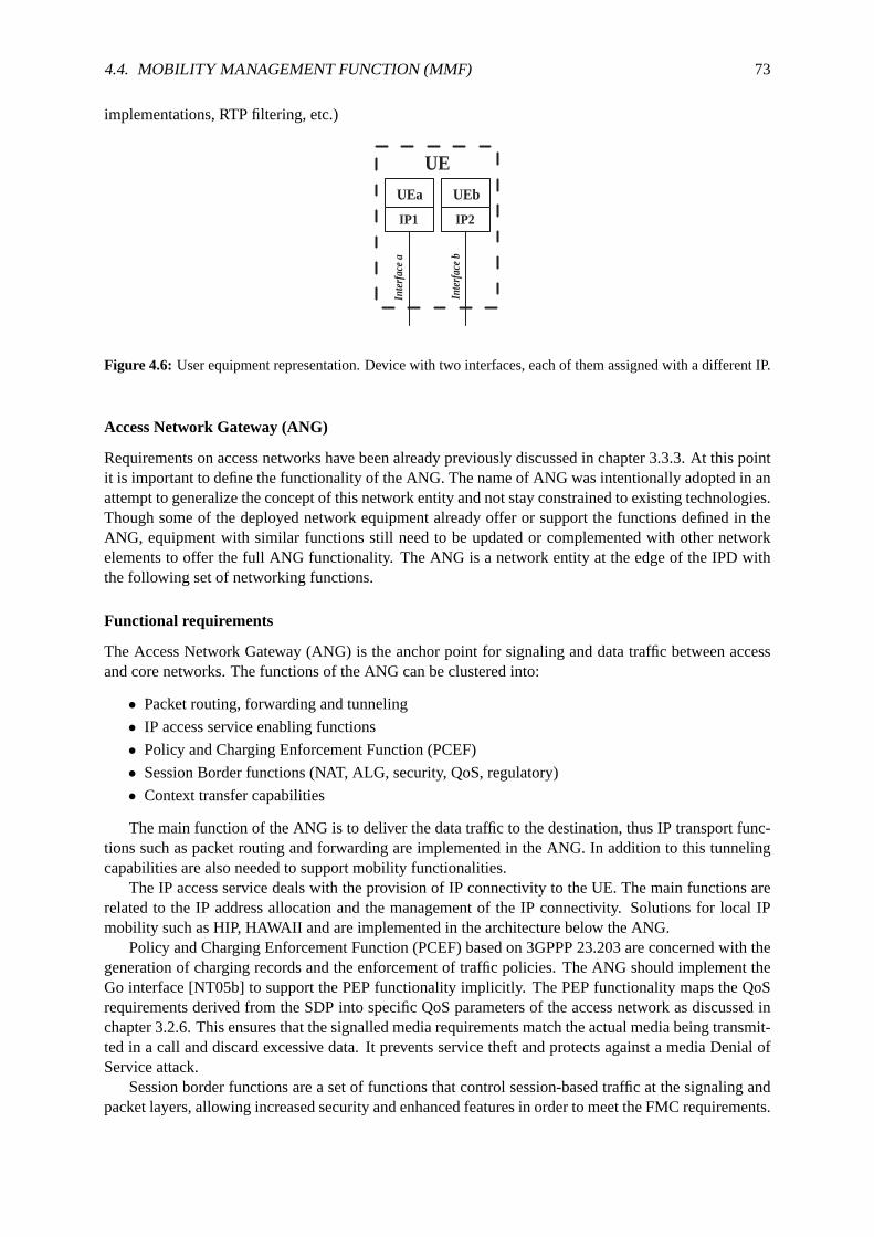
4.4. MOBILITY MANAGEMENT FUNCTION (MMF) 73
implementations, RTP filtering, etc.)
UEb
IP2
UE
Inte
rfac
e b
UEa
IP1
Inte
rfac
e a
Figure 4.6: User equipment representation. Device with two interfaces, each of them assigned with a different IP.
Access Network Gateway (ANG)
Requirements on access networks have been already previously discussed in chapter 3.3.3. At this pointit is important to define the functionality of the ANG. The name of ANG was intentionally adopted in anattempt to generalize the concept of this network entity and not stay constrained to existing technologies.Though some of the deployed network equipment already offer or support the functions defined in theANG, equipment with similar functions still need to be updated or complemented with other networkelements to offer the full ANG functionality. The ANG is a network entity at the edge of the IPD withthe following set of networking functions.
Functional requirements
The Access Network Gateway (ANG) is the anchor point for signaling anddata traffic between accessand core networks. The functions of the ANG can be clustered into:
• Packet routing, forwarding and tunneling
• IP access service enabling functions
• Policy and Charging Enforcement Function (PCEF)
• Session Border functions (NAT, ALG, security, QoS, regulatory)
• Context transfer capabilities
The main function of the ANG is to deliver the data traffic to the destination, thus IP transport func-tions such as packet routing and forwarding are implemented in the ANG. In addition to this tunnelingcapabilities are also needed to support mobility functionalities.
The IP access service deals with the provision of IP connectivity to the UE.The main functions arerelated to the IP address allocation and the management of the IP connectivity. Solutions for local IPmobility such as HIP, HAWAII and are implemented in the architecture below the ANG.
Policy and Charging Enforcement Function (PCEF) based on 3GPPP 23.203 are concerned with thegeneration of charging records and the enforcement of traffic policies. The ANG should implement theGo interface [NT05b] to support the PEP functionality implicitly. The PEP functionality maps the QoSrequirements derived from the SDP into specific QoS parameters of the access network as discussed inchapter 3.2.6. This ensures that the signalled media requirements match the actual media being transmit-ted in a call and discard excessive data. It prevents service theft andprotects against a media Denial ofService attack.
Session border functions are a set of functions that control session-based traffic at the signaling andpacket layers, allowing increased security and enhanced features in order to meet the FMC requirements.

74 CHAPTER 4. SEAMLESS VERTICAL HANDOVERS IN NGN
The P-CSCF already implements some of the required signaling, security and QoS functions, but re-dundant or complementary functions in the access network are still necessary. For the data path, thefollowing required functions related to NAT, security, QoS and regulatoryissues are related:
• Security features should provide protection for core networks elements such as the P-CSCF fromsignaling attacks by identifying malicious traffic before it reaches the core.The CSCF alreadyimplements topology hiding, removing of internal network information carried in the signalingstream to preventing internal details from being propagated. Firewall functionality is needed toallow dynamically open and close multiple ports as required by SIP session establishments.
• Network Address Translation (NAT) [SSH99] is commonly used for IP translation and mapping.It prevents two-way voice and multimedia communication, because the private IP addresses andports inserted by client devices (IP phones, video conferencing stations etc.) in the packet payloadare not routable in public networks. Therefore, NAPT features at layers 3 and 5 are required.
• Application Level Gateway (ALG) is an application specific functional entity that allows an IPv6node to communicate with an IPv4 node and vice versa when certain applications carry networkaddresses in the payloads (e.g. SIP/SDP). While NA(P)T-PT is applicationunaware, ALG al-lows transparent communications between peers running the same applicationbut in a different IPversion.
• Regulatory issues as described in chapter 3.3.2 required lawful interception of user plane traffic.This should be possible at the ANG. The lawful interception of the signaling traffic can also bedone in the P-CSCF and is currently under study in the standardization groups.
• IP transport related functions (e.g. QoS re-mapping, packet marking, shaping, filtering, etc.). TheANG can monitor and optionally re-mark the quality settings of the user’s data (e.g. type of servicebits and DiffServ code point bits). QoS functions can be required to interconnect networks andmap one service provider’s quality setting onto another’s.
The context transfer capabilities allow the exchange of information betweennetwork entities at IPlayer easing mobility across heterogenous access systems as described inchapter 4.3.5.
Mobility Management Function (MMF)
The MMF can be functionally divided into two different elements for a practical implementation. Thecentral part of the functionality is done at the Serving MMF (S-MMF). TheS-MMF is connected to theS-CSCF as an application server using the ISC interface to transport SIPsignaling messages. Initial filtercriteria defined in the user’s subscription profile are used to trigger the MMF services.
Access system dependent functions of the MMF are placed in the Proxy MMF (P-MMF). The P-MMF can be situated in the ANG itself or in the P-CSCF (then, an interface to the ANG is required). Itis not intended by this work to define such interfaces and reference points.
The information stored in the S-MMF has more general scope and can be described as context infor-mation while the information gathered at the P-MMF is more access system specific and can be seen asstate information.
No mobility management solution can be implemented without placing any mobility functions in theUE and in the IP-CAN. One main design objective of the MMF is to minimize the impacts on the UEand access network entities. MMF required at the UE should be access system independent (impactsonly above layer 2). Many of the MMF developed concepts should work even without the availability ofa P-MMF at the access system.
Motivation for a network based mobility management approach
Much efforts have been placed on the design of mobility solutions where the end device plays the majorrole during the mobility operations. As stated in chapter 4.3, the expression "UE better knows" has been

4.4. MOBILITY MANAGEMENT FUNCTION (MMF) 75
true in mobile communications for many years. Now, envisioned NGN aim to make services independentfrom the access network and device type. The rapid advances in technology reduce the value of terminalssince new functions and capabilities are under constant development making older devices look obsolete.
This works tries to explore how the "intelligence" of the mobility process can beplaced in the networkand be reused as much as possible. That does not mean that no mobility support at the end deviceis needed, on the contrary, next generation devices are supposed to be able to handle multiple accesstechnologies. Mobile-controlled and mobile assisted handoff controls will bestill required. This mobilitysupport affects mainly the lower layers and is not possible without UE interaction. But, at higher layersthe involvement of the UE can be highly decreased.
A network intelligence approach enables a smooth migration from the mobile telecommunicationnetwork without any impact on existing mobile terminals. [YOI05] opens a debate on whether mobilitymanagement should be implemented as end-to-end intelligence or network intelligence.
A network based approach satisfies some of the requirements (marked as VHO REQ#num) for avertical handover function (chapter 4.2). The motivation to choose a network based approach for themobility management function includes:
• No or minimal changes in the UE (VHO REQ#5). Changes in the network elementsare easier andlead to increased upgrade capacity.
• Higher performance (VHO REQ#1) is expected due to better network side connection to IMSelements and access to extended network private information. (e.g. HSS and AS queries, PDFaccess and PEP interfaces)
• Reduced signaling overhead at the link path (VHO REQ#2 and REQ#3)(scarcity of radio re-sources, better performance in the core network is expected).
• Operator differentiation. Offering a powerful mobility management functionat the network sideincreases the value offered by a telecom provider.
• MMF can be seen as an IMS resource allowing sharing functionality to otherIMS services andbuilding up enhanced mobility services (e.g. view and move active sessions via web browser).
4.4.3 Domain based mobility
chapter 4.2 pointed out that domain based mobility management is a common technique to achieve highperformance and scalability. The proposed architecture should allow interworking between heteroge-neous (e.g. 3GPP and non-3GPP based) access systems. A mobility protocol takes care of routing IPtraffic to the UE that changes the access system to the IMS. Access systemsare regarded as an edge do-main, within which the UE acquires and keeps the same IP address (IPedge) and where the UE’s mobilityis handled using a local mobility management protocol (e.g. GTP in GPRS). Different edge domainscould choose different local mobility management protocols. Figure 4.7 shows the reference domainbased mobility architecture.
For this domain based mobility approach a Mobility Anchor Point (MAP) is defined as an IP nodethat either:
1. Performs the forwarding and path update of IP packets destined to the moving host.
2. Notifies correspondents that the moving host care-of address has changed.
Thus, a MAP functional entity participates in making a moving host reachable.Local and globalMAP can be distinguished depending on the scope of the mobility they manage.
A local user plane anchor point, named Local Mobility Anchor Point (L-MAP), routes all packetsdestined to IPedge. The moving UE keeps the same IPedge address and it is a task of the mobility protocolto properly update the routing information towards the L-MAP. As later discussed in chapter 4.4.2, theL-MAP can be co-located with the ANG.

76 CHAPTER 4. SEAMLESS VERTICAL HANDOVERS IN NGN
AN
UE
IPD
AN
UE
AN
UE
G - MAP ( IPglobal )
ANG ( IPedge )
L- MAP
ANG ( IPedge )
L- MAP ANG
IP backbone
UE UE
Edge Domain
Local Mobility Global
Mobility Global Mobility
Inter Access System Anchor
Figure 4.7: Reference architecture describing the IMS Provider Domainused in this work.
Any mobility event across the edge domains can be handled by redirecting theUE traffic betweenthe ANG or anchoring the traffic to a fixed anchor referred to as inter access system anchor or GlobalMobility Anchor Point (G-MAP). In order to anchor UE traffic to the G-MAP, two different IP addresseswill be associated to the UE: the IPedge address, belonging to the L-MAP subnet, and an IP addressbelonging to the subnet of the G-MAP (IPglobal). The IPglobal address is the address known at applicationlevel. The UE uses it to communicate with corresponding nodes and is valid as long as the UE remainsconnected to the IPD.
Session continuity is guaranteed since IPglobal does not change whenever an access system changeoccurs (only new a IPedge is assigned). The mobility protocol takes care of updating the route from theG-MAP to the correct L-MAP and bind each new acquired IPedge address to the IPglobal address. Forexample, if MIP were used as the mobility protocol, G-MAP would be the Home Agent (HA), IPedge theCare-of-Address (CoA) and IPglobal the Home Address (HoA).
In case the access system does not support any local mobility managementprotocol (the ANG inthe right in figure 4.7), the IP movement of the UE should be handled by an IP-based global mobilityprotocol and the G-MAP.
4.4.4 Functional overview
The main tasks of the MMF can be summarized in:
1. Collection and managing of information related to the user’s mobility.
2. Execution of handover mechanisms to provide session continuity.
Mapping these tasks in the vertical handover model presented in chapter 4.3 follows to the repre-sentation of figure 4.84. The monitoring and execution steps are tasks done by the MMF defined inthis work. While some kind of evaluation of the available information is needed during the executionphase, the evaluation tasks of this MMF is not meant to trigger handover initiations or participate in thehandover decision.
4The handover model diagram of figure 4.8 intends only to show the relations between the different steps in a verticalhandover and the involvement of the MMF. This model must not be seenas an UML flow diagram.
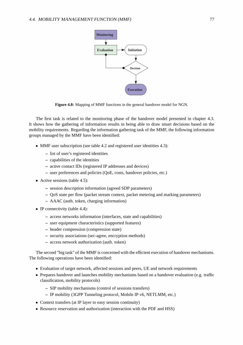
4.4. MOBILITY MANAGEMENT FUNCTION (MMF) 77
Initiation
Decision
Execution
Monitoring
Evaluation
Figure 4.8: Mapping of MMF functions in the general handover model for NGN.
The first task is related to the monitoring phase of the handover model presented in chapter 4.3.It shows how the gathering of information results in being able to draw smart decisions based on themobility requirements. Regarding the information gathering task of the MMF, the following informationgroups managed by the MMF have been identified:
• MMF user subscription (see table 4.2 and registered user identities 4.3):
– list of user’s registered identities
– capabilities of the identities
– active contact IDs (registered IP addresses and devices)
– user preferences and policies (QoE, costs, handover policies, etc.)
• Active sessions (table 4.5):
– session description information (agreed SDP parameters)
– QoS state per flow (packet stream context, packet metering and marking parameters)
– AAAC (auth. token, charging information)
• IP connectivity (table 4.4):
– access networks information (interfaces, state and capabilities)
– user equipment characteristics (supported features)
– header compression (compression state)
– security associations (sec-agree, encryption methods)
– access network authorization (auth. token)
The second "big task" of the MMF is concerned with the efficient executionof handover mechanisms.The following operations have been identified:
• Evaluation of target network, affected sessions and peers, UE and network requirements
• Prepares handover and launches mobility mechanisms based on a handover evaluation (e.g. trafficclassification, mobility protocols)
– SIP mobility mechanisms (control of sessions transfers)
– IP mobility (3GPP Tunneling protocol, Mobile IP v6, NETLMM, etc.)
• Context transfers (at IP layer to easy session continuity)
• Resource reservation and authorization (interaction with the PDF and HSS)

78 CHAPTER 4. SEAMLESS VERTICAL HANDOVERS IN NGN
The S-MMF carries the most important functionality, but it is obvious that MMFrelated functionsare required at the UE and at the ANG. Even if they are intended to be minimal following the networkbased philosophy adopted, functionality required at the ANG are definedas P-MMF functionality andinclude:
• Interaction with the ANG (IP mobility operations e.g. tunnel set up)
• UE state info related to the ANG (UE/user ids, mob state, sec param.)
• QoS (mapping of SDP parameters to AN parameters)
• Context transfers capabilities (with S-MMF and the ANG)
Data structures
The data structures describe the context and state information managed by the MMF. It contains informa-tion related to the user subscription to the MMF, the registered user identities, the IP connectivity relatedinformation and the details about active sessions.
One feature of SIP is the multiple bindings between URI and IP addresses, that means one URI canbe registered at different devices with different IP addresses. IMSdefines an IMS subscription definedby a private URI and unlimited public URIs belonging to the same subscription. Inaddition to this publicURIs may share service profiles or have separated ones. Modern devices are equipped with multiple linkinterfaces (e.g. UMTS/WLAN dual phone) so that a single device may be reachable through different IPaddresses. Taking all these features into consideration, picture 4.9 describes the identified relationshipsbetween IMS subscriptions, public URIs, active sessions, IP addresses and user equipments.
Figure 4.9: Relationship of IMS and SIP identities, active sessions andIP connected devices.
Four data tables have been defined to manage and map the required information elements. Themotivation to choose these parameters and how to obtain the correspondentvalues will be described.The tables are not supposed to be definitive. Extensions and new bindings of information are foreseenas needed in the development of mobility services. The implementation of the databases managing thecollected data is out of the scope of this work.
MMF user subscription
This table should acts as a high level container for the user subscription to the MMF. User’s subscriptionare uniquely identified by theirprivate URIcontained in the Authorization field of the SIP Register mes-
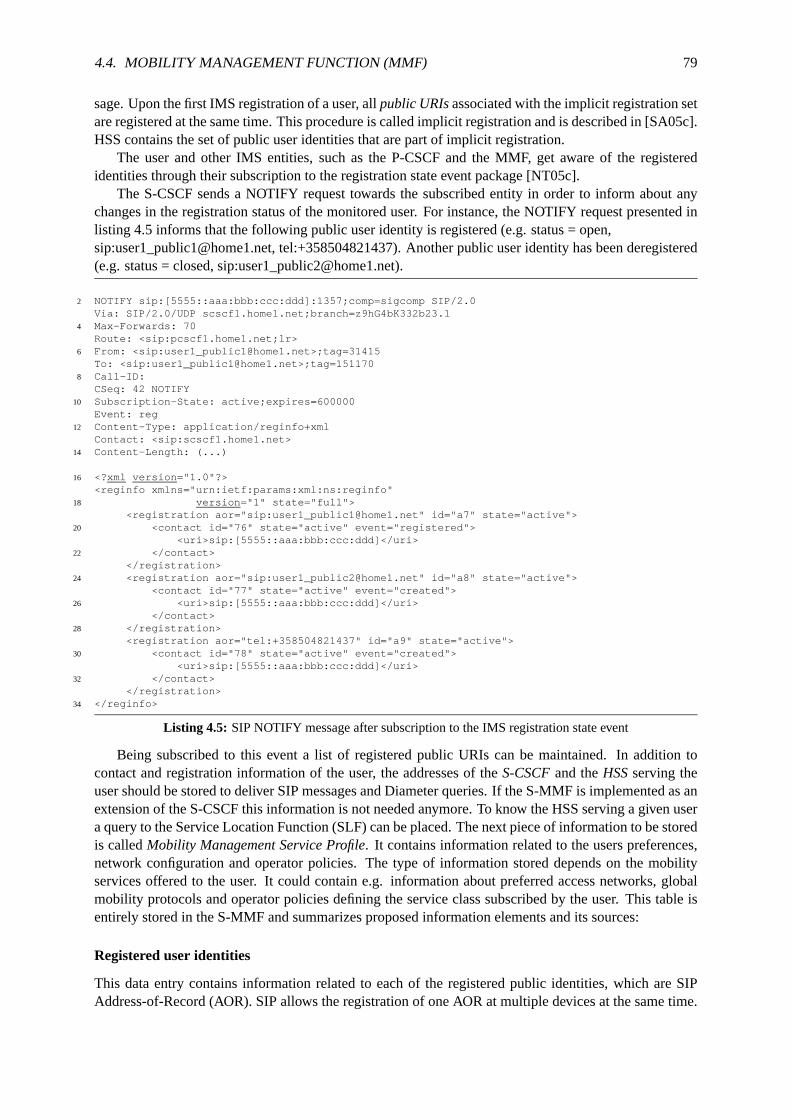
4.4. MOBILITY MANAGEMENT FUNCTION (MMF) 79
sage. Upon the first IMS registration of a user, allpublic URIsassociated with the implicit registration setare registered at the same time. This procedure is called implicit registration andis described in [SA05c].HSS contains the set of public user identities that are part of implicit registration.
The user and other IMS entities, such as the P-CSCF and the MMF, get aware of the registeredidentities through their subscription to the registration state event package [NT05c].
The S-CSCF sends a NOTIFY request towards the subscribed entity in order to inform about anychanges in the registration status of the monitored user. For instance, the NOTIFY request presented inlisting 4.5 informs that the following public user identity is registered (e.g. status =open,sip:[email protected], tel:+358504821437). Another public useridentity has been deregistered(e.g. status = closed, sip:[email protected]).
2 NOTIFY sip:[5555::aaa:bbb:ccc:ddd]:1357;comp=sigcomp SIP/2.0Via: SIP/2.0/UDP scscf1.home1.net;branch=z9hG4bK332b23.1
4 Max-Forwards: 70Route: <sip:pcscf1.home1.net;lr>
6 From: <sip:[email protected]>;tag=31415To: <sip:[email protected]>;tag=151170
8 Call-ID:CSeq: 42 NOTIFY
10 Subscription-State: active;expires=600000Event: reg
12 Content-Type: application/reginfo+xmlContact: <sip:scscf1.home1.net>
14 Content-Length: (...)
16 <?xml version="1.0"?><reginfo xmlns="urn:ietf:params:xml:ns:reginfo"
18 version="1" state="full"><registration aor="sip:[email protected]" id="a7" state="active">
20 <contact id="76" state="active" event="registered"><uri>sip:[5555::aaa:bbb:ccc:ddd]</uri>
22 </contact></registration>
24 <registration aor="sip:[email protected]" id="a8" state="active"><contact id="77" state="active" event="created">
26 <uri>sip:[5555::aaa:bbb:ccc:ddd]</uri></contact>
28 </registration><registration aor="tel:+358504821437" id="a9" state="active">
30 <contact id="78" state="active" event="created"><uri>sip:[5555::aaa:bbb:ccc:ddd]</uri>
32 </contact></registration>
34 </reginfo>
Listing 4.5: SIP NOTIFY message after subscription to the IMS registration state event
Being subscribed to this event a list of registered public URIs can be maintained. In addition tocontact and registration information of the user, the addresses of theS-CSCFand theHSSserving theuser should be stored to deliver SIP messages and Diameter queries. If the S-MMF is implemented as anextension of the S-CSCF this information is not needed anymore. To know theHSS serving a given usera query to the Service Location Function (SLF) can be placed. The next piece of information to be storedis calledMobility Management Service Profile. It contains information related to the users preferences,network configuration and operator policies. The type of information stored depends on the mobilityservices offered to the user. It could contain e.g. information about preferred access networks, globalmobility protocols and operator policies defining the service class subscribed by the user. This table isentirely stored in the S-MMF and summarizes proposed information elements andits sources:
Registered user identities
This data entry contains information related to each of the registered public identities, which are SIPAddress-of-Record (AOR). SIP allows the registration of one AOR at multiple devices at the same time.

80 CHAPTER 4. SEAMLESS VERTICAL HANDOVERS IN NGN
Element name Description MMF Information source
Private URI Unique key for identification S IMS SIP RegisterPublic URIs List of registered COA and IPs S Reg. state subscriptionS-CSCF Serving CSCF IP address S Server assignmentHSS Address of the serving database S SLF / ConfigurationMM Service Pro-file
User preferences, operator poli-cies
S HSS or MMF DB
Table 4.2: MMF user subscription related information is stored in the Serving-MMF.
That means that for each registered Public user identity there might be more than one binded contactIP address. This information is included in theContact IDsfield (e.g. <sip:[5555::aaa:bbb:ccc:ddd];comp=sigcomp>; expires=600000) of SIP messages. It indicates the point-of-presence for the subscriber,that is the IP address of the UE. This is the temporary point of contact for the subscriber that is beingregistered. Subsequent requests destined for this subscriber will be sent to this address.
The Presence Infocontains the data acquired from the registration state subscription for this pub-lic URI. This information could include a registration state (e.g. active, deregistered, etc.) and timerinformation (expiration time, active time).
A list of all active session IDsin which the current public identity is involved should be kept updated.The Call-ID header of the Invite messages will be used as identification for the session. It is a randomidentifier that does not change as long as the session is active.
Active subscriptionsrefer to the SIP subscriptions to events that use this AOR. Storing this informa-tion allows a quicker re-subscription to all events after a contact IP change.
Storing information about theURI capabilitiesis possible since such information may be providedin SIP header field parameters. [SRKS04] defines mechanisms by which a SIP user agent can convey itscapabilities and characteristics to other user agents and to the registrar forits domain (e.g. the MMF).
Element name Description MMF Information source
Public URI Registered AOR (unique key) S Reg. state subscriptionContact IDs List of active contact IP S SIP contact headerPresence info State = active S Presence serverActive sessionIDs
List of active sessions S SIP signaling flows
Active subscrip-tions
User’s subscription to IMS events S SIP signaling flows
URI capabilities Supported methods, content types,extensions, codecs, etc.
S SIP parameters, SIP OPTIONSmethod
Table 4.3: Registered user identities data is entirely centralized inthe Serving-MMF
IP connectivity
The IP connectivity table (table 4.4) gathers information about each IP address associated with an activeand registered public identity. Recall that SIP allows the binding of multiple IP addresses to one SIPAOR. [SRSC+02] specifies a q-value value used to prioritize addresses in the list of contact addresses.
<sip:[5555::aaa:bbb:ccc:ddd];comp=sigcomp>;expires=600000;q=0.6,2 <sip:[4444::aaa:bbb:ccc:ddd];comp=sigcomp>;expires=6000;q=0.1)
Listing 4.6: SIP Contact header including expiration time and priority

4.4. MOBILITY MANAGEMENT FUNCTION (MMF) 81
This table contains in theAN infofield information about the access network (AN) type and charac-teristics attached to this IP address. IMS specifies a new SIP parameter called P-Access-Network-Info.It allows the UE to provide information related to the access network it is using (e.g. P-Access-Network-Info: 3GPP-UTRAN-TDD; utran-cell-id-3gpp=234151D0FCE11). Derived from this information theMMF can determine the access network type (e.g. 3GPP-UTRAN-TDD) andits capabilities. Networkcapabilities could include mobility protocol support (e.g. MIP), expected QoS, costs, etc. This informa-tion could be contained in an internal database. Further on, the use of dynamic information regardingthe actual status of the access network conditions (e.g. data load in the attached cell) could extend theavailable information.
If 802.21 [Soc05] technology is available, Media Independent Handover Information Server (MIHIS) could assist the handover process of 802.21 equipped mobile nodes. MIH Information Services[SDFHD06] may be used to assist handovers between networks based on stored network knowledge.Information Services can provide essential network related information (e.g. topology, channel informa-tion, adjacent base-station channel occupation, neighboring network information or upper-layer mobilityservice information). This allows a moving host to select an appropriate link-layer connection to make,amongst available networks independently of the link technology used [SHFV06].
Alternatively, the Candidate Access Router Discovery (CARD) [SLSC+05] protocol is a recent out-come of the IETF Seamoby WG [SIET05] that specifies similar procedures toensure the capacity andcapabilities of target networks.
In order to identify the visited network at the home network, the P-CSCF also adds the P-Visited-Network-ID header with the contents of the visited network identifier.
One of the difficulties observed in the IMS addressing functionality is the difficulty to bind IP ad-dresses to terminals or SIP User Agents (UA). Regarding the given specifications of SIP and IMS there isno way to detect that a single device uses more than one IP address. In addition to this, the address maychange each time the device running the user agent gets a new IP address, but it is very reasonable forthe display name to give a unique identifier for what this instance of the user agent wishes to be known.
This is the main motivation for including adevice IDfield.It would be useful being able to bind IPaddresses to unique, long-term, stable identifier for a particular user agent. For example, when severalpresence user agents are providing presence data, it should be possible to correlate a particular set of datawith the particular device that provided it.
The User-Agent header field specified in RFC 3261 [SRSC+02] cannot be used for these purposessince the information about the UAC is not unique. Two softphones using thesame version would addthe same information (e.g. User-Agent: Softphone Beta1.5).
The identification of SIP UA is not a new idea and possible solutions are already being discussedin Internet Drafts [Jen05]. This work addresses the requirements using a contact header tag that lookslike +sip.instance="value", where the value is a Uniform Resource Name (URN) that uniquely identifiesthe device. Today, the most practical URN to use is the Universally Unique Identifier (UUID) URN asspecified in [SLMS05]. There are two main approaches for this numberingscheme. One approach isusing a random number to provide a high likelihood of uniqueness. An alternative is using an admin-istratively defined such as ethernet MAC addresses to allow a given device to be manufactured with aunique address. The UUID defines a simple way of encompassing either orboth of these approaches andworks for both hard phones and soft phones.
Having a way to identify the available devices allows extending the description of the devices withits capabilities (UE capabilities). An initial SIP Invite includes the SDP offer containing a descriptionof all the supported codecs by the device. Storing this initial SDP information enriches future mediacommunications.
The information about the terminal capabilities could be also extended in a similar way as the infor-mation about the access network is retrieved. If the MMF knows the terminal type (e.g. manufacturer,model, OS version) a database could provide useful information about supported services and capabilitiesof the terminal, mobility management protocols (MIPv6) and other specific characteristics.

82 CHAPTER 4. SEAMLESS VERTICAL HANDOVERS IN NGN
The SIP method OPTIONS defined in [SRSC+02] allows a UA to query another UA or a proxy serveras to its capabilities. One approach could be using the OPTIONS requests to discover information aboutthe supported methods, content types, extensions, codecs, etc. The SIP OPTIONS method could querynot only the communicating peers but also the P-CSCF and other SIP capableentities to gain informationabout the supported services and codecs in one network (enrichingAN info field information). Thisapproach can be regarded as an alternative MIH Information Service implementation. This informationmay be later used during the handover to determine a SDP matching all device and network capabilities.
The S-MMF stores in this table also the address of theP-MMF handling the user IP connection.Depending on the implementation the P-MMF could be in the P-CSCF or could havea different IPaddress. In either case sending IP messages to the P-CSCF serving the user is enough to reach the P-MMF. The address of the P-CSCF is available at theVia-routeheader of all SIP messages. When theP-MMF has another IP address it is necessary to set up the trigger pointsin the P-CSCF to deliver themessages to the P-MMF.
The P-MMF needs an interface or reference point to theANG responsible for the user traffic of thisIP address. How to get this information is a matter of the specific access system implementation andavailable technologies. It is assumed that the P-MMF is aware of the ANG at the IP-CAN managing thisIP connection.
Information related to theAAAcould include authentication information (e.g. authentication vectors)and authorization data (e.g. Auth. token). If the P-MMF is provided with an authentication vector asdescribed in the IMS registration procedure, then it is not further necessary to query the HSS and theauthentication challenge could be issued at the proxy side. In either case,the authentication of thechallenge response should be done at the home network by the S-CSCF.
Header compression (HC) is done at the P-CSCF to optimize the radio resources towards the mobilenode. Mobile node and P-CSCF negotiate in their first IMS communication the compression used (e.g.comp=sigcomp). Header compression implies maintaining compressor state information at the P-CSCFthat could be transferred to save the compression negotiation and set up time.
Something similar happens regarding the security agreements (SA) between the P-CSCF and the UE.During the IMS registration the security parameters and algorithms are negotiated. It is for further studyat the handover process how the transfer of this information could be useful. (e.g. Security header in SIPmessages: Security-Verify: ipsec-3gpp; q=0.1; alg=hmac-sha-1-96; spi-c=98765432; spi-s=87654321;port-c=8642; port-s=7531). Extended information about IMS securityschemes is available in [PMKN04,SA05c].
Element name Description MMF Information source
Contact ID Contact IP (key) S SIP REGISTER contact infoPublic URI Registered CoA S IMS registrationAN info AN type and capabilities S-P P-Access-Network identifiersMIH IS 802.21 MIH Information Server S Queries to MIH ISDevice ID unique, binds IPs and ports S IP-CAN registration, USIMUE capabilities MM protocols, codecs, BW, S First SDP offers, SIP contact
header field parametersP-MMF Assigned to the P-CSCF S Via-route infoANG Serving ANG P PEP, AN infoAAA Authentication tokens, ids, S-P Auth. header IMS reg flow, IP-
CAN specific AAAHC Header compression state in P-
CSCFP SigComp negotiation
SA Security agreements with P-CSCF P Security-tags
Table 4.4: IP connectivity information is distributed in the Proxy andServing MMF.

4.4. MOBILITY MANAGEMENT FUNCTION (MMF) 83
Active session description
This table contains all relevant information regarding the active sessions.Storing this information allowsmaking smart decisions about the requirements of the ongoing services. The Session IDuniquely iden-tifies a SIP communication session and acts as a key to bind active sessions withother data elements.Since every SIP session is tagged with a Call ID, this ID can be used as the unique identification for thesession. The Call-ID is present in all SIP messages and is maintained as longas the session is alive (e.g.Call-ID: cb03a0s09a2sdfglkj490333).
TheURIs and IP addressesof the communicating partners are also stored and can be extracted fromtheFrom: To: headers of the SIP Invite messages (e.g. <sip:[email protected]>;tag=171828)and from the connection field of the SDP body (e.g. c=IN IP6 5555::aaa:bbb:ccc:ddd).
The most important piece of information stored in this table is the session description informationthat can be extracted from the body of the negotiatedSDP. It contains all the necessary information todescribe the ongoing session including codecs, bitrates, bandwidth and transport protocols. From thisinformation the MMF can derive the required QoS and draw conclusions about the necessary mobilitymanagement protocols to assure session continuity. A SDP description example for a session usingvideo (port 10001, codec H263, bandwidth 75 kbit/s.) and audio (port 6544, codec AMR, bandwidth25.4 kbit/s.) over RTP is:
2 v=0o=- 2987933623 2987933625 IN IP6 5555::eee:fff:aaa:bbb
4 s=-c=IN IP6 5555::eee:fff:aaa:bbb
6 t=0 0m=video 10001 RTP/AVP 98
8 b=AS:75a=curr:qos local sendrecv
10 a=curr:qos remote sendrecva=des:qos mandatory local sendrecv
12 a=des:qos mandatory remote sendrecva=rtpmap:98 H263
14 a=fmtp:98 profile-level-id=0m=audio 6544 RTP/AVP 97 96
16 b=AS:25.4a=curr:qos local sendrecv
18 a=curr:qos remote sendrecva=des:qos mandatory local sendrecv
20 a=des:qos mandatory remote sendrecva=rtpmap:97 AMR
22 a=fmtp:97 mode-set=0,2,5,7; mode-change-period=2a=rtpmap:96 telephone-event
24 a=maxptime:20
Listing 4.7: SDP description for a session using video (port 10001, codecH263, bandwidth 75 kbit/s.) and audio(port 6544, codec AMR, bandwidth 25.4 kbit/s.) over RTP
Theflow identifiersdescribe the IP data flow used (if any). This feature is also access system specificand the transfer of this information could not be always useful. But flow description could also enrichedthe information about the session and help extracting the QoS and service requirements of the ongoingsession.
The last information element is theCharging Infocontaining Call Details Record (CDR) such asthe IMS Charging Identifier (ICID), the Charging Collection Function (CCF) and the Charging GatewayFunction (CGF). Details and specifications are available in [SA05a]. The CDR information can be verylarge and rich in terms of describing the session (timers, components, bandwidths, etc.). It can be veryhelpful to store this information to allow the correlation of charging information during context transfersbetween access networks.

84 CHAPTER 4. SEAMLESS VERTICAL HANDOVERS IN NGN
Element name Description MMF Information source
Session ID Unique key for session identifica-tion
S-P Call ID tag
IP IP address S-P SDP c: fieldCN URI Corresponding node URI S-P SIP INVITECN IP Corresponding IP S-P SDP c: fieldSDI Session description information S-P SDP body in final INVITEFlow identifiers Data flow description (e.g. PDP
context in GGSN)P IP-CAN, PEP
QoS state IP-CAN specific QoS parameters(e.g. UMTS class)
P P-MMF Database
Charging info CDR including ICID, CCF, CGF P-S P-CSCF, P-Charging vector
Table 4.5: Active session description requires storage of information in the P-MMF.
S-MMF assignment
Upon IMS registration the user gets a S-MMF assigned that will serve the user as long as it is connectedto the IMS. The assignment can be based on load balancing, user capabilities or further criteria.
One implementation option is to define a trigger points in theinitial filter criteria stored in the user’ssubscription profile. After successful IMS registration the S-CSCF getsthough theinitial filter criteriaas described in chapter 3.2.1. A trigger point can be set to contact an AS responsible for the S-MMFassignment.
The user and the S-MMF could perform a SIP event registration to get know each other and stayin contact about MMF events. After S-MMF assignment, theRecord-Routeheader may be set in SIPrequests to stay in the signaling path. More details about possible implementationsremain for furtherwork.
4.4.5 Vertical handover operations
The steps during a vertical handover are summarized in the following steps:
1. Handover starting conditions include getting IMS connectivity over the new available interfaceand access network. UE gets a second IP address and discovers the new IMS entry point. IMSregistration procedures of new contact address are required.
2. Handover initiation indicate the need for a handover upon reception of a trigger.
3. Handover evaluation is based on active session characteristics and available networks and af-fected end-points.
4. Handover executionstarts required mobility mechanisms to support session continuity (e.g. sendre-INVITE messages to ongoing session participants).
Handover starting conditions
Before starting to think about any handover procedure, IMS connectivity is required. This includesattachment to the IP-CAN, P-CSCF discovery and IMS registration of the new contact IP.
The mobile node connects to the mobile wireless network via any access technology (e.g. CDMA,GPRS, 802.11, 802.16e etc.) through a second network interface. Afterestablishing L2 connection withthe network, the mobile node initiates L3 establishment by requesting an IPv6 address from the IP-CAN.There are various ways the mobile node can request for an IPv6 address (e.g. IPv6CP [SHA98], IPv6stateless address auto-configuration [STN98] or DHCP).

4.4. MOBILITY MANAGEMENT FUNCTION (MMF) 85
The P-CSCF discovery has been introduced in chapter 2.5.1 and can be done by means provided bythe IP-CAN or using DHCP. After reception of domain name and IP addressof the P-CSCF the UE mayinitiate communication towards the IMS and perform IMS registration and authentication procedures asdescribed in chapter 2.5.1.
Terminal authentication is granted by the new access network that providesconnectivity. Chapter3.2.5 introduced the security features of IMS and established means for combined authorization andauthentication mechanisms as a FMC requirement. With this regards, innovativeSIP based terminalauthentication strategies are discussed.
SIP based terminal authentication: A new method for terminal authentication for IMS based net-works is proposed. Access network are responsible to provide connectivity, but the authorization pro-cedures need the query of a database containing the AAA data. Thus, theaccess system needs accessto this data. Providing each access system with an interface towards the HSSis not cost-effective. Alocal copy of the AAA authorization data is another approach but the replication of sensible subscriberinformation is also very problematic. FMC requirements include the re-use of existing AAA methods inan a technology independent way.
Taking these considerations into account, this approach suggests the implementation of a SIP UA atthe access network entity (let it be the ANG) that receives the authenticationrequest of the user as usual(e.g. line id in xDSL networks, International Mobile Station Identifier (IMSI)for GPRS authentication).With these authentication parameters a SIP Register message is constructed and sent by the ANG to theCSCF. If the CSCF accepts the registration and authenticates the user, the ANG grants connectivity tothe terminal and follows with the IP allocation procedures. Then, the user can register with the IMS asusual.
Figure 4.10 shows a UE requesting terminal authentication as usual. The request is passed to theAAA entity, in this case the ANG (a proxy AAA may be defined for this purposes as in WLAN inter-working [SA06a]). The ANG implements a SIP layer and transforms the authentication request in a SIPRegister message containing the authentication parameters. Means to locate thehome network from theauthentication information are required to forward the Register message correctly. The CSCF authenti-cates the registration by querying the HSS and sends a SIP response, either 200 OK or 401 Unauthorized.The SIP aware ANG translates the response in an access network specific authentication response that issent to the UE.
UE SIP - aware AAA entity ( e.g. ANG)
Auth . Req . SIP Register
SIP Register Response .
HSS CSCF
Auth . Resp .
Authentication
Figure 4.10: Terminal authentication.
Alternatively, a further enhancement is possible through an one-pass IP-CAN and IMS authenticationprocedure. Such an approach would save network traffic and reduce the IMS registration time by bindingthe IP-CAN authorization and the IMS authentication procedures. During IMS registration, the ANGproviding AAA functionality inserts an authentication token. This token is generated or stored duringthe terminal authentication procedure, either during a standard or the proposed SIP based access network

86 CHAPTER 4. SEAMLESS VERTICAL HANDOVERS IN NGN
authentication. The SIP register message containing the authentication token isforwarded as usual to theS-CSCF. The S-CSCF downloads from the S-CSCF the subscription profile and registration state fromthe user that contains terminal registration info permitting to check the validity of the authenticationtoken. If authenticated, the S-CSCF does not need to progress with the authentication vector registrationprocedure (sending a temporary410 Unauthorizedresponse as in steps 7 and 8 of figure 2.4) and cansend a final200 OKmessage. Such an approach is described for the case of GPRS in [LCHW05].
SIP flexibility allows to use such methods for any type of authentication data andmechanism. Theonly requirement is that the UA implementation at the ANG and S-CSCF are the same. SIP behavesmainly as a transport protocol to carry the authentication data. Benefits of this approach are:
• Maintains HSS centralized architecture as specified for IMS.
• Re-uses SIP signaling.
• Authentication answer can be extended with access subscription info (QoSprofile etc.).
• One pass terminal and IMS authentication is possible.
• Reduces overall user registration time.
Further considerations should include:
• Mapping of access id to SIP URI (Mapping of AAA information to home CSCF in order to be ableto route the SIP registration request)
• SIP aware layer implementation at the ANG
• Slight modification of SIP message format
In the following, another approach for IMS authentication is presented.
ANG pinghole for terminal authentication based on IMS registration: In this innovative ap-proach, the ANG assigns a temporal IP address to the terminal providing theUE with limited IP capa-bilities. This procedure borrows the principle of the Universal Access Method (UAM), a browser-baseduser authentication and authorization method used widely in many public hotspots. With this method,any IP-based device with a Web browser that supports Secure SocketLayer (SSL) can login and be au-thenticated to the hot spot network. Only after authentication the user has full access to Internet services.
The ANG opens only a port for SIP communications. The terminal can use thistemporal IP addressonly for IMS registration. Other traffic flows are barred. If the terminal does not complete a successfulIMS registration within a time, the ANG should remove completely the limited IP connectivity to theterminal. Benefits of this approach include there is no need for terminal specific authentication. But,the drawbacks are associated to the temporary provision of IP connectivity, which highly increases thesecurity risks on the ANG and the P-CSCF.
IMS (fast) registration: After gaining IP connectivity IMS registration as defined in [SA05c] anddescribed in chapter is required before a transfer of services to the new access network can happen.A fast IMS registration that profits from the information of the IMS registration over the old interfaceshould be possible.
Because the INVITE dialog was established using an IMS secured signaling path and because thedialog identifiers are cryptographically random [SRSC+02], no entity except for user agent in UE or theproxies (CSCFs) on the path of the initial INVITE request can know the dialog identifiers.
[SRea05] specifies a Target-Dialog header field for (SIP), and the corresponding option tag,tdialog.It indicates to the recipient that the sender is aware of an existing dialog with the recipient, either becausethe sender is on the other side of that dialog, or because it has access to the dialog identifiers. TheTarget-Dialog field can be used as an authorization parameter in the SIP REGISTER message and the S-CSCFcan then authorize the request based on this awareness.
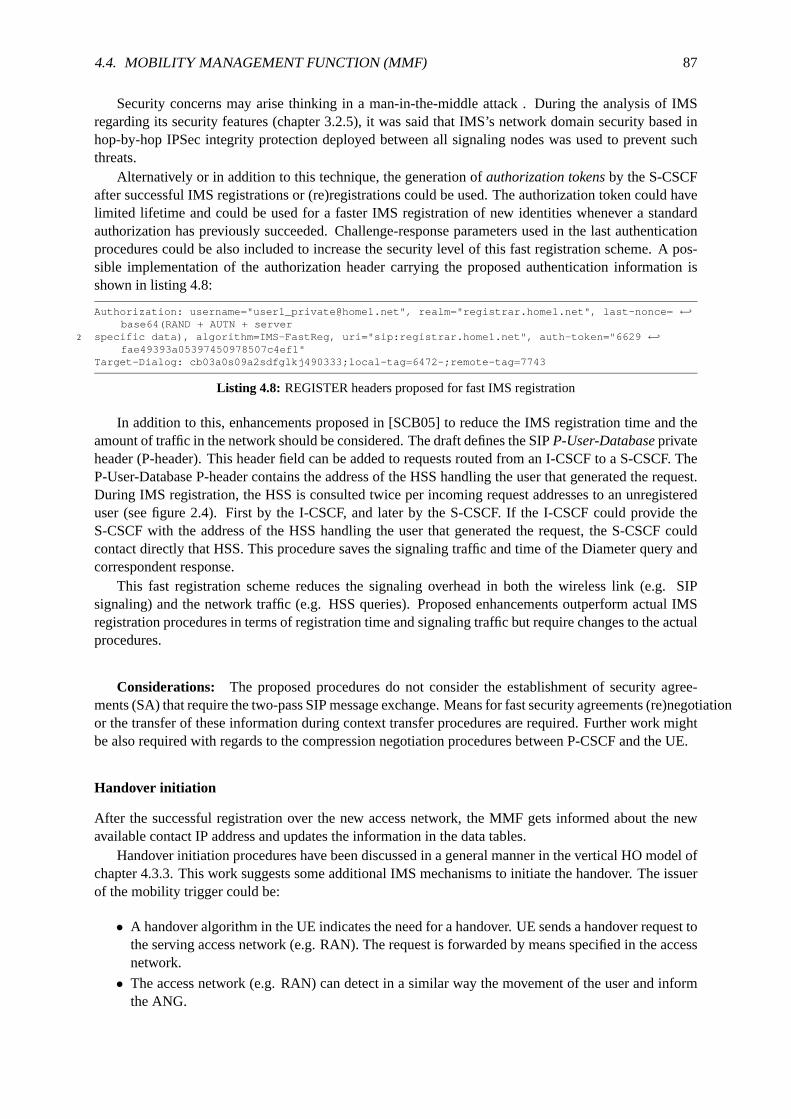
4.4. MOBILITY MANAGEMENT FUNCTION (MMF) 87
Security concerns may arise thinking in a man-in-the-middle attack . During the analysis of IMSregarding its security features (chapter 3.2.5), it was said that IMS’s network domain security based inhop-by-hop IPSec integrity protection deployed between all signaling nodes was used to prevent suchthreats.
Alternatively or in addition to this technique, the generation ofauthorization tokensby the S-CSCFafter successful IMS registrations or (re)registrations could be used. The authorization token could havelimited lifetime and could be used for a faster IMS registration of new identities whenever a standardauthorization has previously succeeded. Challenge-response parameters used in the last authenticationprocedures could be also included to increase the security level of this fast registration scheme. A pos-sible implementation of the authorization header carrying the proposed authentication information isshown in listing 4.8:
Authorization: username="[email protected]", realm="registrar.home1.net", last-nonce= ←֓base64(RAND + AUTN + server
2 specific data), algorithm=IMS-FastReg, uri="sip:registrar.home1.net", auth-token="6629 ←֓fae49393a05397450978507c4ef1"
Target-Dialog: cb03a0s09a2sdfglkj490333;local-tag=6472-;remote-tag=7743
Listing 4.8: REGISTER headers proposed for fast IMS registration
In addition to this, enhancements proposed in [SCB05] to reduce the IMS registration time and theamount of traffic in the network should be considered. The draft defines the SIPP-User-Databaseprivateheader (P-header). This header field can be added to requests routed from an I-CSCF to a S-CSCF. TheP-User-Database P-header contains the address of the HSS handling the user that generated the request.During IMS registration, the HSS is consulted twice per incoming request addresses to an unregistereduser (see figure 2.4). First by the I-CSCF, and later by the S-CSCF. Ifthe I-CSCF could provide theS-CSCF with the address of the HSS handling the user that generated the request, the S-CSCF couldcontact directly that HSS. This procedure saves the signaling traffic andtime of the Diameter query andcorrespondent response.
This fast registration scheme reduces the signaling overhead in both the wireless link (e.g. SIPsignaling) and the network traffic (e.g. HSS queries). Proposed enhancements outperform actual IMSregistration procedures in terms of registration time and signaling traffic but require changes to the actualprocedures.
Considerations: The proposed procedures do not consider the establishment of security agree-ments (SA) that require the two-pass SIP message exchange. Means forfast security agreements (re)negotiationor the transfer of these information during context transfer procedures are required. Further work mightbe also required with regards to the compression negotiation procedures between P-CSCF and the UE.
Handover initiation
After the successful registration over the new access network, the MMFgets informed about the newavailable contact IP address and updates the information in the data tables.
Handover initiation procedures have been discussed in a general manner in the vertical HO model ofchapter 4.3.3. This work suggests some additional IMS mechanisms to initiate the handover. The issuerof the mobility trigger could be:
• A handover algorithm in the UE indicates the need for a handover. UE sends a handover request tothe serving access network (e.g. RAN). The request is forwarded bymeans specified in the accessnetwork.
• The access network (e.g. RAN) can detect in a similar way the movement of theuser and informthe ANG.
88 CHAPTER 4. SEAMLESS VERTICAL HANDOVERS IN NGN
• [SA05c] defines how the PDF should inform P-CSCF about changes atthe bearer changes. Thisbehavior may be used to trigger the HO. This applies for the above described UE and AN handovertriggers.
• SIP UA in the users device sends SIP message to the serving MMF. This approach requires a mod-ification in the user’s device. The SIP message (e.g. REFER, INFO, MESSAGE) triggering thehandover. The message can be sent through the interaction of the user or automatically generatedby other means of the device and applications.
• The MMF based on defined rules or algorithms starts the handover mechanisms upon a contextchange. User preferences should be considered. Context information in the MMF can be veryrich.
It is assumed that a handover indication triggered by non SIP capable entities contains the requiredinformation related to the desired handover, describing session or sessions to move and target network.How a UE can decide when to start the handover procedure is out of scope of the MMF, please refer tothe chapter 4.3.3 or [oGMCT00] for more details.
Handover evaluation
Upon reception of the handover initiation request, the MMF evaluates the request considering the avail-able information. Then, mobility strategies are chosen to fulfill the identified requirements for seamlesssession continuity.
On going media traffic description in the SDP body allows a traffic type classification. The traffictype classification using the information from the session description table 4.5 includes:
RT / nRT classification: based on the transport protocol used (e.g. TCP for non RT traffic, RTP for RT)
Session QoS requirements:From the SDP information the bandwidth field, the used codecs and bi-trates allow to. Static information about the active service type could include a QoS parametersrange (min. / max. values). The Call Detail Record (CDR) at the chargingfunctions of the networkalso provides access network specific information about the active sessions. [SA05a] defines theformat and fields and of the CDR definition.
From the available context information the current state and capabilities of thenetwork and enddevices should be evaluated:
Network capabilities: Stored in the IP connectivity table 4.4. Proactive strategies include accessto theinformation services of the available access networks (e.g. as defined in 802.21) or using the SIPOPTIONS method to query the P-CSCF.
Device capabilities: From session description information in table 4.5 and the mechanisms for obtainingthis information described in the IP connectivity table 4.4.
The criteria for choosing the mobility mechanisms should include:
1. Session adaptation capabilities required due to new network or device conditions
2. Ongoing service QoS requirements (e.g. SDI, max. packet delay, jitter,packet losses)
3. Need of TCP support (no support in standard SIP)
4. User’s mobility management service profile (see table 4.2)
An evaluation engine determines whether SIP mobility mechanisms are enough to move the sessionsto the new access system or if a user data mobility strategy (e.g. Data tunneling, MIPv6) is needed.For some services (e.g. TCP connections) IP continuity is needed and special IP mobility strategies arerequired.

4.4. MOBILITY MANAGEMENT FUNCTION (MMF) 89
The support of different service types without modifications to TCP has been identified as REQ#6 inchapter 4.2. Internet applications that require a reliable service from thetransport mechanism, such asFile Transfer Protocol (FTP), primarily use TCP. Thus, it is essential that the proposed approach supportmobile TCP applications without requiring any changes to the TCP.
SIP and TCP have different means to identify the connection. SIP uses a call ID to identify a SIPsession/connection, while a pair of endpoints (host IP, port) identifies a TCP connection. However, as amobile node roams, its IP address changes and the TCP session breaks since the underlying TCP/UDPsocket addresses will no longer be valid for the changed IP address [HDS03].
Network and device capabilities (e.g. mobility protocols implementation, SIP extensions support) inconjunction with the session characteristics and user preferences should form the criteria for deciding onrequired handover mechanisms. Decision techniques described in chapter 4.3.4 can be used. A detailedspecification of the handover evaluation engine is out of the scope of this work.
Handover execution
As mentioned before, the basic SIP does not provide seamless handovermanagement. The MMF shouldbe able to execute different mechanisms to meet the mobility requirements of the active sessions. Inorder to achieve seamless mobility, SIP mechanisms need to be complemented with IMS functions andIETF solutions. Support for different mobility protocols should be considered.
In order to achieve a soft handover, proposed solutions should followthe principles of "make-before-break". Make-before-break is possible since the UE supports several access technologies. Sessionsover the source access system should be released only when the session over the target access system iscomplete. In the following, different SIP and IP based mobility mechanisms areproposed.
4.4.6 SIP based handover mechanisms
The fundamental idea of the proposed SIP mobility approach is to have the S-MMF act as a third partycontrol (3pcc) [SRPSC04] during the handover. The S-MMF initiates SIP mechanisms to move thesessions affected by the mobility. This approach is based on the SIP REFERmethod [SSpa03] to requestthe transfer of an ongoing session to the new contact address of the moving node.
The REFER method [SSpa03] always begins within the context of an existingcall and the issuerof the request is called the originator. The originator sends a Refer request to the recipient to initiatea triggered Invite request. The SIP URL contained in the Refer-To header is used as the destination ofthe triggered Invite request. The recipient returns a SIP 202 (Accepted) response to the originator toacknowledge the correct processing of the Refer request. The recipient also must notify the originatorof the outcome of the Refer transaction indicating the status of the session establishment with the finalrecipient (Refer-To URL). This indication is accomplished using the Notify method (event notificationmechanism of SIP). If the session set up is successful, a call between the recipient and the final recipientresults.
The originator of the REFER request could be the moving user itself, but thisnetwork based approachintends to explore how a network based mobility using SIP methods could work.In this case, having theMMF be the originator of the REFER request5, the next step is to decide who is going to be the recipientof the request. There are 3 candidates:
1. The moving node through the old IP address
2. The moving node through the new IP address
3. The communicating node
5The concepts presented in this work to use REFER to handle SIP terminal mobility can be easily adapted to provide sessionmobility across different terminals. [Pro02] approaches session mobility with SIP and the current related IETF work in progressis available in [SSSTK06]

90 CHAPTER 4. SEAMLESS VERTICAL HANDOVERS IN NGN
The first discussion should outline the benefits of sending the request to the moving or to the corre-spondent node. A first design considered were that informing the CN about the movement of the node inbehalf of the user could be a nice idea. Though this approach reduces the signaling towards the movingnode, it was realized soon that this option arises more security considerations and highly increases therequirements on the UA of the CN. The CN should overcome the security concerns of a request out-side a dialog from a third party. In addition to this, the CN must support the REFER method (optionalin RFC3261) and additional functionality might be required (see inclusion ofSDP body in the REFERmessage in chapter 4.4.6).
It is more reasonable to move these requirements to the UE attached to the provider offering theMMF service. Additionally, the signaling towards the moving UE might be more efficient if the UE islocated in the home network. The next considerations are regarding the destination address of the movingnode, the older point of attachment or the newer one. Though option (1) could seem to be more natural(old contact IP already in the session dialog), it has to be considered thatthe mobility trigger might becaused by a decrease in the connectivity level in the source access network and a disconnection is morelikely to occur. In chapter 4.4.5 has been assumed that the new IMS contactidentity is ready to be used,so it is reasonable to start using the new signaling path as soon as possible.The session re-establishmentfollows the required procedures of SDP negotiation, resource reservation and session setup confirmationpresented in chapter 2.5.2.
Based on the concepts for session transfers detailed in [NT05c] a general approach for mobilityusing SIP is presented in figure 4.11. The I-CSCF for IMS interconnection is not included for the sake ofsimplicity. The moving user (UE#2) has IMS connectivity as described in chapter 4.4.5 via P-CSCF#2aand P-CSCF#2b. A step-by-step description of the information flow is presented in figure 4.11:
P- CSCF #1 UE # 2a UE #1 S- CSCF #1 S- MMF #2 S- CSCF #2 P- CSCF # 2a
4. Refer
1. Session in progress
UE # 2b P- CSCF # 2b
6. Refer 5. Service Control
7. Refer
21. Service Control
24. Completion of Session Initiation
8. Accepted 9. Accepted
12. Notify 13. Notify
10. Accepted 11. Notify
14. OK 15. OK 16. OK
17. Invite 18. Invite
20. Invite
22. Invite
19. Service Control
23. Invite
27. Notify 26. Notify 25. Notify
28. OK 29. OK 30. OK
3. Target P- MMF / ANG Selection
2. Handover Initiation
31. Session Release
Figure 4.11: MMF mobility approach for vertical handovers using SIP mechanisms.
1: Session in ProgressA multi-media session is assumed to already exist between UE#1 and UE#2.

4.4. MOBILITY MANAGEMENT FUNCTION (MMF) 91
2: Handover InitiationThe handover initiation is triggered as suggested in chapter 4.4.5.
3: Target P-MMF/ANG SelectionThe target P-MMF and ANG are selected based on the network and registration information.
4,6-7: REFER (S-MMF#2 to S-CSCF#2)MMF sends a REFER request to the serving S-CSCF#2 of UE#2 (see Table 4.9).
1
REFER sip:[5555::aaa:bbb:ccc:ddd]:1357;comp=sigcomp SIP/2.03 Via: SIP/2.0/UDP [5555::aaa:bbb:ccc:ddd]:8805;branch=z9hG4bK834y72.2
Max-Forwards: 705 Route: <sip:scscf2.home2.net:5088;lr>, <sip:pcscf2.home2.net;lr>
Privacy: none7 From: <sip:smmf2.home2.net>;
To: <sip:[email protected]>;9 Call-ID: cb03a0s09a2sdfglkj490333
Cseq: 130 REFER11 Require: sec-agree
Proxy-Require: sec-agree13 Security-Verify: ipsec-3gpp; q=0.1; alg=hmac-sha-1-96; spi-c= 22334455; spi-s ←֓
=11223344; port-c=6199; port-s=5088Contact: <sip:[5555::eee:fff:aaa:bbb]:8805;comp=sigcomp>
15 Refer-To: <sip:[email protected]>
Listing 4.9: REFER (S-MMF#2 to S-CSCF#2)
5: Service Control (S-CSCF#2)S-CSCF#2 invokes whatever service logic is appropriate for this request. If UE#2 is not subscribedto a transfer service, service logic may reject the request.
8-10: 202-Accepted (UE#2b to S-MMF#2)UE#2b acknowledges receipt of the REFER request (7) with a 202 (Accepted) final response, sentto P-CSCF#2b.
11-13: NOTIFY (UE#2b to S-MMF#2)A REFER request implicitly establishes a subscription to the refer event [SSpa03]. So, once theREFER method is accepted, the UE sends a NOTIFY message to inform the REFER issuer (theMMF).
14-16: 200 (OK) (S-MMF#2 to UE#2b)S-MMF#2 acknowledges receipt of the NOTIFY request (18) with a 200(OK) final response.
17,18,20,22,23:INVITE (UE#2b to UE#1)
19,21: Service Control (S-CSCF)The S-CSCF of each user invokes whatever service logic is appropriatefor this request. For ex-ample, to hide the identities of the users the service logic may store theRefer-ToandReferred-Byinformation and replaces them with private URIs.
24: Completion of Session InitiationUE#1 and UE#2 complete the session initiation as defined in the 3GPP specifications [NT05c]. Nochanges are required in the session initiation. The session initiation procedures are well definedand no changes should be even considered.
25-27: NOTIFY (UE#2b to S-MMF#2)When the session with UE#1 has been successfully established, UE#2b sends a NOTIFY requestto the serving MMF as required by the subscription to the REFER event.
28-30: 200 (OK) (S-MMF#2 to UE#2b)S-MMF2 acknowledges receipt of the NOTIFY request (27) with a 200 (OK) final response.
31: Session releaseThe old session can be now released as defined in [NT05c] by sending BYE messages and the
92 CHAPTER 4. SEAMLESS VERTICAL HANDOVERS IN NGN
correspondent OK acknowledgements.
Issues and solutions
Though the proposed mechanism offers the basis to support basic vertical mobility in IMS, some issuesrelated to SIP and IMS can be identified and need to be addressed:
• No seamless session mobility
• Two sessions simultaneously active
• Security and privacy
No seamless session mobility: Becomes an issue for real time multimedia applications. Requirementsfor a vertical handover introduced in chapter 4.2 require a session transfer to be as seamless as possible.It should involve minimal disruption of the media flow and should not appear to the remote participantas a new call (VHO REQ#1 in chapter 4.2).
Soft handovers implies that the traffic flows are continuously available whilethe mobile-node link-layer connection transfers from the serving point of attachment to the target point of attachment. Thenetwork allocates transport facilities to the target point of attachment prior tothe occurrence of thelink-switch event. [DKea05] presents an experimental analysis of multi-interface mobility managementthat demonstrates how seamless handovers can be achieved in a heterogeneous network (802.11b andCDMA) taking advantage of a make-before-break mechanisms.
One source of potential session discontinuity is the time to complete the necessary control signalingfor session transfer between communicating devices. Another source ofdiscontinuity is the media streaminterruption caused by the session transfer with SIP from the original communicating interface to the newone. In the following, the main sources that affect the seamlessness of thehandover are discussed:
• Overall handover delay
• Content adaptation required
• No seamless handover management in basic SIP
Overall handover delay: Is a main issue for RT services and may cause large packet looses if theconnection via the old interface breaks before the session mobility is completed. The overall delay canbe minimized with the use of context transfers (as introduced in chapter 4.3.5)or message interceptiontechniques. Message interception techniques are later described in section 4.4.6 and context transfers arealso suggested to ease user’s mobility.
SIP signaling delay in real operator environment has been proofed to becomparable to PSTN calls.The session initiation delay defined in [KH02] yields 1880 milliseconds in the worst case IMS scenario(caller and called in visited networks). Additional delays are expected when the calls break out to tele-phony networks. The bearer set up at the access networks may vary considerably from one technologyto the other. [NDDS03] describes delay elements to be taking into account when comparing handoffstrategies.
Conclusions about the real overall handover delay can only be drawntesting the procedures in a realworld or testbed scenario, which is part of the future work.
Content adaptation with a transcoding service: SIP allows the communicating parties to agreeon the session characteristics through SDP negotiation mechanisms. [Pro01] describes practical tests andevaluation of different ways in which SIP in conjunction with SDP could be used to assist applicationadaptation for IP applications during a vertical handover.
Though SDP offers great possibilities, one shortcoming of the SDP negotiation during session es-tablishment in IMS is that no session establishment is possible if no common codecis available. The
4.4. MOBILITY MANAGEMENT FUNCTION (MMF) 93
IMS should provide means to support this scenarios. One example could betwo devices trying a videoconference with no common video codec. Furthermore, one could thing about speech recognition andtext-to-speech for impaired users or Short Message Service (SMS) to speech similar services.
The ABC concept and the service transparency features (see chapters 3.2.6 and 3.2.3) of convergedNGN networks require means for flexible adaptation [SSSTK06]:
Flexibility: Differences in device and network capabilities should be reconciled. It should be possible todevices and networks that do not support the codec being used in the session, and even to devicesthat do not have a codec in common with the remote participant. A transfer should also take intoaccount device differences in display resolution and bandwidth.
The later part regarding device differences is solved through the renegotiation of the SDP parametersduring IMS session reestablishment. The inclusion of a message body in the REFER message can assistthe moving node to chose the preferred SDP for the new session. The main motivation is that the MMFhas more information about the service requirements, access network capabilities and user preferencesthan the user’s device. The MMF proposes a SDP for the new session that meets all the requirements,however the final decision should still rely on the user. However, this mechanisms requires changesat the UAC behavior that needs to read the body of the REFER and use it for the INVITE message.The specifications of the REFER method in RFC 3515 [SSpa03] considers the inclusion of a messagebody: "A REFER method MAY contain a body. This specification assigns no meaning to such a body. Areceiving agent may choose to process the body according to its Content-Type."
When device and/or network incompatibilities are found means for content adaption are required.It is important to recall that following the policy decision functions during session establishment, theP-CSCF can remove unsupported medias and the S-CSCF can removed barred components of the SDP(see chapter 3.2.6). In the worst case, a common supported codec couldnot exist. The use of transcodingservices can help to successfully move the session.
The execution of the session mobility can be carried out through an intermediate transcoding service.3pcc (third party call control) [SRPSC04] discusses how to perform theinvocation of such transcodingservices.
Separate sessions are established between the transcoder and each ofthem, with the transcoder trans-lating between the streams. The Multimedia Resource Function Processor (MRFP) in IMS has beenintroduced in chapter 2. It provides advanced services e.g. multiparty calls that require the various sig-nals to be mixed. The MRFP is controlled by a Multimedia Resource Function Controller (MRFC). Thetranscoding services could be performed using these media resource functions of IMS.
This approach borrows concepts of [SCBSvW05] to use third-party call control for transcoding ser-vices in the context of IMS. For simplicity, the MRFC and MRFP are shown together as MRF. In additionto this, the path via the CSCF is not shown. Standard IMS procedures at theCSCF are assumed (e.g.service control, resource reservation, etc.). The MMF has the information about the supported codecs ofUE#1 from the session in progress and knows the SDP offer from UE#2b. The MMF detects the incom-patibility a priori or after a first session mobility trial. Then, the MMF starts the transcoding servicesin MRF as shown in figure 4.12. For the sake of simplicity CSCF elements have been left out in thesignaling flows.
1: Session in progress
2: Handover initiation
3: INVITE (MMF to MRF)The MMF that initiates the transcoding services initiating a media session with the MRFC. Theinitial INVITE sent by the MMF to the MRFC includes a session description referring to the UE#1and the UE#2.
4: 200 OK (MRF to MMF)The MRFC response includes its own media parameters (X for UE#1 and Y for UE#2b), namelythe ports on which the MRFP will receive and process each stream.

94 CHAPTER 4. SEAMLESS VERTICAL HANDOVERS IN NGN
MRF UE # 2a UE #1 MMF
3. INVITE UE1 and UE2b parameters
UE # 2b
1. Session in progress
2. Handover Initiation
4. OK X , Y parameters
5. INVITE Y parameters
6. OK UE2b parameters
7. RTP
8. ACK 9. INVITE
X parameters
10. OK UE1 parameters
12. RTP
13. ACK UE1 , UE2b parameters 14. RTP 15. RTP
11. ACK
Figure 4.12: Transfer of a session by the MMF through the MRF to perform transcoding between UEs withoutcommon codec.
5: INVITE (MMF to UE#2b)The MMF establishes a session with UE#2b, in which it gives the address and port of the transcoderas the destination of the media (MRFP contact information).
6: 200 OK (UE#2b to MMF)acknowledges the session establishment including the UE#2b parameters.
7: RTP (UE#2b to MRFP) UE#2b can start sending the RTP stream to the MRFP.
8: ACK (MMF to UE#2b)Acknowledges the success of the session establishment.
9-11: Same procedures as in (5), (6), (7) and (8) for session initiation with UE#1.
12: RTP (UE#1 to MRFP) UE#1 can start sending the RTP stream to the MRFP.
13: ACK (MMF to MRF)Includes the parameters of UE#1 and UE#2b and MRF can now start sending the transcoded RTPflows.
14-15: RTP (MRFP to UE#1 and UE#2b)
Once both sessions are established, two media streams have been established through the MRFtranscoder. In other SIP flow diagrams (e.g. figures 4.11 and 4.14), thecomplete session initiationsteps were skipped by referring to the IMS standards[NT05c]. As explained in chapter 2.5.2, the IMSsession set up is more complex than just the INVITE-OK-ACK message flow shown in figure 4.12.
At this point, it is aimed to illustrate the so known "early media" phenomena. Note that the first RTP
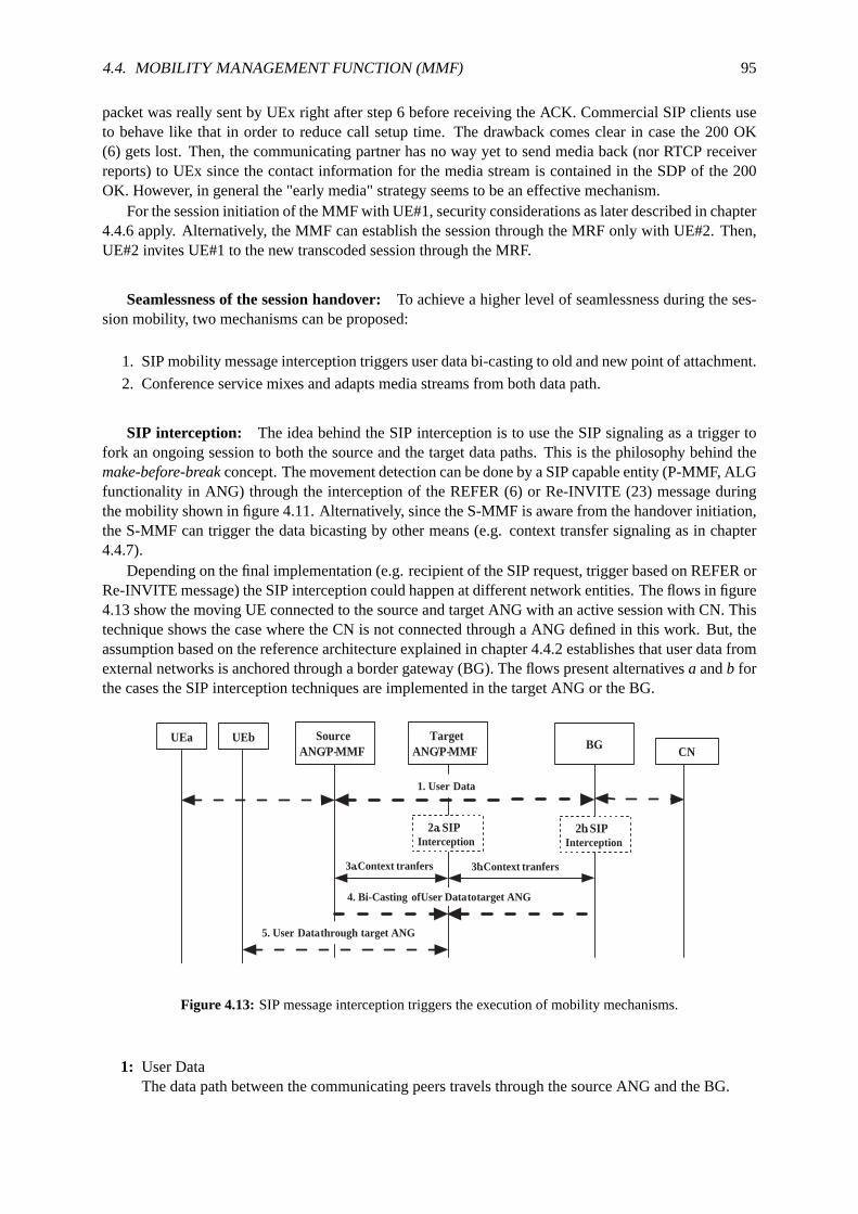
4.4. MOBILITY MANAGEMENT FUNCTION (MMF) 95
packet was really sent by UEx right after step 6 before receiving the ACK. Commercial SIP clients useto behave like that in order to reduce call setup time. The drawback comes clear in case the 200 OK(6) gets lost. Then, the communicating partner has no way yet to send media back (nor RTCP receiverreports) to UEx since the contact information for the media stream is containedin the SDP of the 200OK. However, in general the "early media" strategy seems to be an effective mechanism.
For the session initiation of the MMF with UE#1, security considerations as laterdescribed in chapter4.4.6 apply. Alternatively, the MMF can establish the session through the MRFonly with UE#2. Then,UE#2 invites UE#1 to the new transcoded session through the MRF.
Seamlessness of the session handover:To achieve a higher level of seamlessness during the ses-sion mobility, two mechanisms can be proposed:
1. SIP mobility message interception triggers user data bi-casting to old and newpoint of attachment.
2. Conference service mixes and adapts media streams from both data path.
SIP interception: The idea behind the SIP interception is to use the SIP signaling as a trigger tofork an ongoing session to both the source and the target data paths. Thisis the philosophy behind themake-before-breakconcept. The movement detection can be done by a SIP capable entity (P-MMF, ALGfunctionality in ANG) through the interception of the REFER (6) or Re-INVITE (23) message duringthe mobility shown in figure 4.11. Alternatively, since the S-MMF is aware fromthe handover initiation,the S-MMF can trigger the data bicasting by other means (e.g. context transfer signaling as in chapter4.4.7).
Depending on the final implementation (e.g. recipient of the SIP request, trigger based on REFER orRe-INVITE message) the SIP interception could happen at different network entities. The flows in figure4.13 show the moving UE connected to the source and target ANG with an active session with CN. Thistechnique shows the case where the CN is not connected through a ANG defined in this work. But, theassumption based on the reference architecture explained in chapter 4.4.2establishes that user data fromexternal networks is anchored through a border gateway (BG). The flows present alternativesa andb forthe cases the SIP interception techniques are implemented in the target ANG or the BG.
CN UEa Source
ANG /P- MMF BG
1. User Data
UEb
4. Bi- Casting of User Data to target ANG
Target ANG /P- MMF
2a . SIP Interception
2b . SIP Interception
3b . Context tranfers 3a . Context tranfers
5. User Data through target ANG
Figure 4.13: SIP message interception triggers the execution of mobility mechanisms.
1: User DataThe data path between the communicating peers travels through the source ANG and the BG.

96 CHAPTER 4. SEAMLESS VERTICAL HANDOVERS IN NGN
2a: SIP interception (at target ANG)The movement of the user can be detected at SIP layer by intercepting a REFER or a Re-INVITEmessage.
2b: SIP interception (at BG)Same as in 2a.
3a: Context transfers (target and source ANG)The target ANG request the transfer of context information to enable the set up of a new datapath to UEb. Context information at source ANG includes QoS parameters, charging information,media authorization tokens, etc.
3b: Context transfers (target ANG and BG)In this case, the BG is the entity having the context information and transferingit to the targetANG.
4: Bicasting of user data (to target ANG)The result of the context transfers have the same end, the set up of a data path to the target ANGand the bi-casting or the data towards UE.
5: User Data through target ANG (target ANG to UEb)UE receives the data coming from the CN by both active interfaces. The make-before-break strat-egy success and the connection over the source access system can betorn down.
The main benefits of forking the session to the new data path are:
• Handover occurs in a transparent manner for the CN.
• Overcomes incompatibility and security issues (see 4.4.6) related to the REFER method.
• Bi-casting technique increases the level of seamlessness of the mobility.
• Reduced E2E signaling may decrease overall handover delay.
The reduction of the delay is stated in a "may" clause since real conclusionswill highly depend inthe final implementation of the mobility mechanism 4.4.6. Context transfers, tunnelset up and optionalcontent adaption techniques could increase the delay up to levels that are comparable to the SIP sessionestablishment time in IMS.
The moving terminal has simultaneously two IP connections open. One with the CNvia the sourceinterface and another one terminating in the ANG. The later one presents sometechnical difficulties toconsider. The difficulties associated with this solution include:
• Breaks even more the E2E signaling philosophy of SIP.
• High assumptions on ANG and BG implementations (e.g. knowledge of S-MMF andANG ad-dresses)
• Requires a signaling reference point between the P-MMF and the ANG or SIP capable ANG(extended ALG functionality).
• No SDP negotiation available, other means for content adaption may be required (e.g. MRF as inchapters 4.4.6, pre/post-SDP negotiation as described in chapter 4.4.7).
• Data traffic tunneling mechanisms are required.
• Context transfers implementation (see chapter 4.3.5) to authorize and set upincoming data stream(authorization, charging, QoS set up, etc.) in target ANG.
These drawbacks make this SIP interception and forking approach difficult, though such approachescomplementing SIP mobility mechanisms should be considered. The combination of SIP with other IPtransport techniques can achieve high performances (e.g. multicast services during handover). It is amatter of further study how the different combinations of mechanisms and protocols can optimize thehandover process.

4.4. MOBILITY MANAGEMENT FUNCTION (MMF) 97
SIP Message interception techniques could be also used when SIP incompatibilities are detected.For example, if the CN does not support some SIP extensions (e.g. REFERmethod) required for themobility, alternative mechanisms should be available to support session continuity.
Conference service: This approach is inspired in the idea of the transcoding service previouslydescribed in chapter 4.4.6. In order to satisfy the seamless mobility requirements for real time sessionsduring vertical handovers, a conference service can be used. Such a conference service anchors thetraffic coming from both communicating parties, provides means for session adaptation and "smoothes"the connection to the moving node during the handover. It enhances the seamless communication duringa short time period by adapting the media streams coming from the two interfaces of the moving nodeand the stream from the CN. Techniques to achieve its include but are not limited to buffering, RTPfiltering, de- and encoding, bicasting, etc.
The implementation is based on the conferencing functions of IMS provided by the multimediaresource functions (MRFC and MRFP) [FILea05]. This solution also addresses the resources problemdescribed in chapter 4.4.6 related to the fact that the CN could need two simultaneous connections toUE#2 to increase the seamlessness of the handover.
When a handover is signaled, the MMF starts a conferencing service in thehome network. The par-ticipants are the two registered contacts of the moving UE and the corresponding communicating partner.The conference function copies the media stream and sends it to both terminal’s point of attachments.The conferencing approach mixes the two media streams for the corresponding node. The conferenceservice acts as an anchor point for the communication and can provide means for buffering and sessionadaptation. One way to set up such a conference service is described below. The same assumptions as inchapter 4.4.6 apply:
1: Session in ProgressA multi-media session exists between UE#1 and UE#2.
2: Handover InitiationThe handover initiation is triggered 4.4.5.
3: REGISTERConferenceName(MMF to MRF)The MMF creates a conference by sending a REGISTER message to the MRF conference serviceindicating the conference name in the To: field and the duration in the Expires:field.
4: 200 (OK) (MRF to MMF)The OK reply contains the contact information for the conference.
5: REFER (S-MMF#2 to UE2#b)MMF sends a REFER request to UE#2b including the conference servicecontact information anda proposal for the SDP to be used.
6: INVITE (UE#2b to MRF)UE#2b joins the conference by sending an INVITE to the conference service hosted in the MRF.The 202-Accepted reply to the REFER message is not shown for simplicity.
7: Completion of Session InitiationThe MRF and UE#2b complete the session initiation following the IMS procedures [NT05c]. The200 OK response from the MRFC contains the port and the address of theMRFP to which UE#2bmust send the media.
8: NOTIFY (UE#2b to MMF)A NOTIFY request informs serving MMF about the success of the session establishment.
9-10: REFER (MMF to UE#1 and MMF to UE#2a)As in (5) the MMF request UE#1 and UE#2b to join the conference by meansof the REFERmethod. Alternatively, once again, the issuer of the REFER message could be UE#2 instead of theMMF.

98 CHAPTER 4. SEAMLESS VERTICAL HANDOVERS IN NGN
MRF UE # 2a UE #1 MMF
3. REGISTER conference
UE # 2b
1. Session in progress
2. Handover Initiation
4. OK contact parameters 5. REFER
conference param ., SDP
6. INVITE
7. Completion of Session Initiation
10. REFER
8. NOTIFY 9. REFER
conference param ., SDP
11. INVITE 12. INVITE
13. Completion of Session Initiation
15. Notify
16. Session Release
14. Stream Mixing
Figure 4.14: MMF Conference service to achieve seamless mobility duringvertical handovers
11-12: INVITE (UE#1 to MRF and UE#2a to MRF)See (6)
13: Completion of Session Initiation (UE#1-MRF and UE#2a-MRF)See (7)
14: Stream MixingDepending on the type of session the MRFP performs the necessary actions (Buffering, RTP fil-tering, de- and encoding, etc.) to mix the streams coming from UE#2a and UE#2b. UE#1 receivesa single continuous stream. In the other direction the MRFP adapts each stream and sends themover the two paths to the UE#2.
15: NOTIFY (UE#2a to MMF and UE#1 to MMF)A NOTIFY request informs serving MMF about the success of both session establishment. Op-tionally the MRFC can inform the owner of the conference, the MMF, aboutthe changes in theconference.
16: Once the UE#2b and UE#1 are sending and receiving streams with QoS guarantees the old session(1) can be now released as defined in [NT05c].
UE#2b and UE#1 can now use SIP means to setup a direct connection between them and leave theconference system. The conference system helped to ensure a seamless session handover and is notnecessary anymore (if no media handling functions are required).
Variations of the proposed signaling scheme can be studied. In steps 9 and10 a SIP INVITE withthe Join [SMP04] orReplaceheaders [SMBD04] can be used. TheJoin header indicates that the newdialog of the INVITE containing the Join header should be logically joined with adialog identified by

4.4. MOBILITY MANAGEMENT FUNCTION (MMF) 99
the header field. Upon reception of the INVITE with theJoin header, the UA attempts to match thisinformation with a confirmed or early dialog. If it matches an active dialog (notethat unlike the Replacesheader, the Join header has no limitation on its use with early dialogs), the UA verifies the authenticityof the INVITE initiator as described in chapter 4.4.6.
It is for further study to evaluate which messaging scheme has less impacts to the network compo-nents and end devices.
Combination with SIP message interception: SIP message interception techniques can be helpfulin several situations as described chapter 4.4.6. In this case it could be used for example to intercept theSIP invitation to the conference and bicast the stream from the CN to the conference service in a transpar-ent way to the CN. Though this technique establishes important requirements on the entity interceptingthe message and forking the data flow (e.g. SIP aware layer, bi-casting capabilities), the advantagesregarding delay reduction and seamlessness improvement (see chapter 4.4.6) are very important.
Two sessions simultaneously active: Until the completion of the session initiation and the BYE mes-sages are processed two active sessions are simultaneously active. This circumstance could carry re-sources and charging issues. The resources issues are related to thefact that the corresponding node issending and receiving data across the wireless link via a single interface.
The corresponding node should not perceive any issues related to thesession mobility. Sessionadaption due to the new access network capabilities requires SDP negotiation, thus a new session needsto be established. The new session is identified by a new Call-ID. The establishment of a new sessionshould not imply new connection fees or rate changes (unless changes inthe media components exist) forthe CN. The charging functions of the moving node network should be updated the transport rates of thenew access network. Therefore, means for identifying that the new session establishment is consequenceof a handover are required. For this purposes, theReplacetag header defined in RFC 3891 [SMBD04]for the INVITE messages can be used. The charging functions located inthe different CSCFs can readthe header and process the charging actions correctly. Other requiredactions can be triggered by thereception of the Replace header. For example, procedures for handling the resources of the old sessionat the IP-CAN. The Replace header in the SIP message requires adding the lines from listing 4.10 in theINVITE messages.
1 Require: replacesReplaces: cb03a0s09a2sdfglkj490333;to-tag=7743;from-tag=6472
Listing 4.10: Replace header in SIP INVITE for session handover identification
Security: Some concerns about the correctness and feasibility of issuing a REFER message outsidea call dialogue may arise. There are similar uses of this usage of the REFER method in the literature[FILea05].The specification of the REFER method [SSpa03] states:"A REFER request MAY be placedoutside the scope of a dialog created with an INVITE."
Letting the S-MMF to move sessions on behalf of the user requires having thetrust of the CN toavoid security threats. Additional authorization mechanisms for the REFER method are required tofulfill the security requirements. Three SIP extensions to the REFER method may overcome the securityconsiderations:
• Target-Dialog header [SRea05]
• Replaces header [SMBD04]
• Referred-By header [SSpa03]
The Target-Dialogheader [SRea05] and theReplacesheader [SMBD04] are based on the sameprinciple but differ on their scope. The principle relies on the knowledge of the dialog identifiers (call-id, to-tag, and from-tag) of the ongoing session. Including these identifiers in a SIP request assures
100 CHAPTER 4. SEAMLESS VERTICAL HANDOVERS IN NGN
the receiving UA (e.g. UE#1) that the request came from either UE#2, theCSCF proxies, or an entityto whom the UE#2 or proxies gave the dialog identifiers. As such, UE#1 authorizes the request andperforms the requested action.
The Target-Dialogheader could be used in any type of SIP request while the Replaces header hasbeen defined for INVITE messages (see 4.10). TheTarget-Dialogmay refer to another active sessionwith the CN. The moving node could replace a current session and include the dialog information ofanother session to double check its authenticated identity. [SRea05] recommends the inclusion of aTarget-Dialog header field in a request under these conditions:
1. The request is to be sent outside of any existing dialog.
2. The user agent client believes that the request may not be authorizedby the user agent server unlessthe user agent client can prove that it is aware of the dialog identifiers forsome other dialog. Callthis dialog the target dialog.
3. The request does not otherwise contain information that indicates that the UAC is aware of thosedialog identifiers.
Like other SIP extensions it is required that the destination user agent supports the Target-Dialogheader field. The MMF needs to ensure that the destination has included thetdialog option tag in theuser supported header field.
UE#2b initiates an INVITE request based on theRefer-Toheader URL in the REFER request. TheINVITE request includes aReplacesheader field [SMBD04] containing the dialog information sharedwith the communicating party UE#1.
The Referred-Bymechanism [SSpa03] defines a mechanism that allows the CN to verify that therequest was sent on behalf of the other participant in the matched dialog. If the SIP request contains aReferred-Byheader that corresponds to the user being replaced, the CN should treat the replacement asif the replacement was authorized by the replaced party.
The proposed solutions are complementing rather than exclusive. A final design should considerthat the Target-Dialog and the Replaces header information may be redundant. They may be used in theREFER and INVITE requests and require the inclusion of the following headers and tags:
Require: replaces, tdialog2 Target-Dialog: cb03a0s09a2sdfglkj490333;local-tag=6472-;remote-tag=7743
Replaces: cb03a0s09a2sdfglkj490333;to-tag=7743;from-tag=64724 Referred-By: <sip:[ue2a address]>
Listing 4.11: SIP extensions to handle security considerations
Additionally, authentication mechanisms of standard SIP can be used. This includes sharing the samecredentials for Digest authentication [SFHBH+99] or signing the join request with S/MIME [SRam04].The Referred-By header should reference a corresponding valid Refererred-By Authenticated IdentityBody [SPet04].
Other local policy to authorize the remainder of the request may be applied. The authorization of therequest could be also relied to the IMS CSCF. The CSCF of the originating and receiving nodes couldprovide they own means to allow only authorized request pass through. For instance, the issuer of aREFER message can place in the Referred-By field only the contact address of another URI registeredto the same private URI.
4.4.7 IP based handover approaches
As discussed in chapter 4.4.5, under some circumstances e.g. service type, network or device capabilities,the MMF decides to execute other mobility mechanisms than SIP to meet user’s mobilityrequirements.One example is when IP continuity is required (e.g. TCP traffic support).
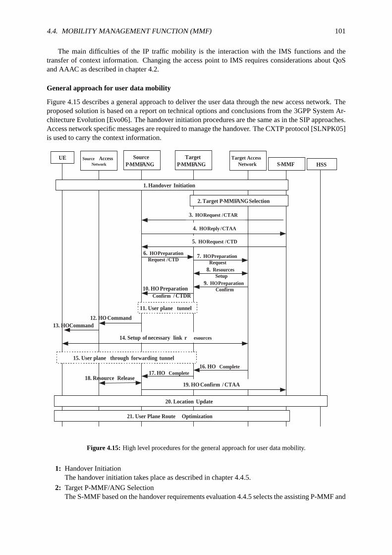
4.4. MOBILITY MANAGEMENT FUNCTION (MMF) 101
The main difficulties of the IP traffic mobility is the interaction with the IMS functions and thetransfer of context information. Changing the access point to IMS requires considerations about QoSand AAAC as described in chapter 4.2.
General approach for user data mobility
Figure 4.15 describes a general approach to deliver the user data through the new access network. Theproposed solution is based on a report on technical options and conclusions from the 3GPP System Ar-chitecture Evolution [Evo06]. The handover initiation procedures are thesame as in the SIP approaches.Access network specific messages are required to manage the handover. The CXTP protocol [SLNPK05]is used to carry the context information.
Source Access Network HSS
UE Source P- MMF / ANG
Target P- MMF / ANG
Target Access Network S- MMF
1. Handover Initiation
2. Target P- MMF / ANG Selection
3. HO Request / CTAR
6. HO Preparation Request / CTD
7. HO Preparation Request
8. Resources Setup
9. HO Preparation Confirm 10. HO Preparation
Confirm / CTDR
11. User plane tunnel
14. Setup of necessary link r esources
15. User plane through forwarding tunnel
20. Location Update
21. User Plane Route Optimization
16. HO Complete 17. HO Complete
18. Resource Release 19. HO Confirm / CTAA
4. HO Reply / CTAA
5. HO Request / CTD
12. HO Command 13. HO Command
Figure 4.15: High level procedures for the general approach for user datamobility.
1: Handover InitiationThe handover initiation takes place as described in chapter 4.4.5.
2: Target P-MMF/ANG SelectionThe S-MMF based on the handover requirements evaluation 4.4.5 selects theassisting P-MMF and

102 CHAPTER 4. SEAMLESS VERTICAL HANDOVERS IN NGN
target ANG. The S-MMF prepares the required context information. Thisshould include a queryto the PDF to get a media authorization token for the moving session.
3: HO Request - CTAR (S-MMF to source P-MMF)The S-MMF request the target P-MMF to initiate the HO by sending a CT Activate Request(CTAR) [SLNPK05]. The CTAR contains the Feature Profile Type (FPT)codes indicating thetype of context data to be transferred.
4: HO Reply - CTAA (source P-MMF to S-MMF)The Context Transfer Activate Acknowledge (CTAA) message acknowledges the CTAR message.The functionality defined in [SLNPK05] is extended to include in the CTAA newstatus codes forto indicate that a FPT transfer is not required (e.g. the source P-MMF may already have the latestinformation). FPTs should include a status code indicating that a desired context information ismissing.
5: HO Request - CTD (S-MMF to source P-MMF)After processing the CTAA the S-MMF sends a Context Transfer Data (CTD) message filling theContext Data Block (CDB) fields for each acknowledged FPT. The CDBscontain context type-dependent data about the moving sessions, the target network and the user’s credentials.
6: HO Preparation Request - CTD (source P-MMF to target P-MMF)The source P-MMF sends a CTD to the target P-MMF extending the CTB received from the S-MMF with its own contest information. A CTAR - CTAA message exchange couldbe perform asin (3) and (4) to negotiate the required and available FPTs.
7: HO Preparation Request (target ANG to target access network)The PEP in the target ANG uses the media token in the CTAR to query the PDF about authorizationof the media session. If media supported specific access network procedures to trigger the handoverare carried out.
8: Resources SetupThe target ANG reserves resources in the access network based on the QoS parameters received inthe CTD message.
9: HO Preparation Confirm (target access network to target ANG)Once the resources for the handover are available the ANG gets a confirmation.
10: HO Preparation Confirm - CTDR (target P-MMF to source P-MMF)A Context Transfer Data Reply (CTDR) message is sent to the source P-MMF indicating successor failure of the context transfer and handover procedures.
11: User plane tunnelUser plane traffic mobility mechanisms redirect the user data and minimize data lossby means ofbi-casting or data forwarding.
12-13: HO CommandStep 10 indicates the completion of the handover preparation phase. The source ANG sends ahandover command to the UE via the L2 access network.
14: Setup of necessary link resourcesThe UE sets up the necessary radio resources with the target access network.
15: User plane through forwarding tunnelThe UE can send and receive IP packets via the new access network. The IP traffic goes throughthe tunnel set up in (11)
16-19: HO Complete and resource releaseThese steps are maintenance procedures. Confirmation of handover completion and release ofresources in the source system.
20: Location updateThe maintenance procedures of the location update depends on the access system architecture. The

4.4. MOBILITY MANAGEMENT FUNCTION (MMF) 103
information about the target ANG is updated at the MMF and the registered withthe HSS.
20: User Plane Route OptimizationThis procedures are required to optimize the data paths a network resources. Depending on theMM protocol used different signaling messages are required. The forwarding tunnel that may havebeen set up in (11) is no longer used and can be thorn down.
One could note that since the MMF knows the target ANG, the HO Request (3-5) could be sentdirectly to the target ANG. This approach makes sense if the source ANG cannot provide any additionalcontext information (6) to the target ANG. In either case, a tunnel (11) needs to be setup and thereforefurther message exchanges between the source and target ANG are required.
Steps 7-9, 16 and 18 involve network entities from the access system. The concrete procedures aretherefore system dependent and may highly differ from one access technology to the other. Furtherresearch is required considering the individual requirements of each technology at these steps. Mappingof context information to system specific parameters is required.
The setup of the user plane tunnel in step 11 is intentionally described in a general manner. Dif-ferent techniques may be considered to deal with the user plane mobility forwarding the data streamsbetween the ANGs. After a survey of the available technical solutions and research trends the study hasbeen limited to three mobility protocols candidates. The motivation for choosing these options is thefollowing:
GTP: Is the tunneling protocol used in GPRS networks to support IP mobility 3.5.1. It satisfies all therequirements from an telecommunications provider regarding QoS provision, resource reservation,charging functions, lawful interception, etc.
MIPv6: Combines the enhancements of IPv6 and the experience gained with MIPv4 offering impor-tant features like route optimization or no need for FA. Many extensions are still under work inprogress. MIPv4 feasibility has been proofed for 3G networks by 3GPP2.
Network based MIP: Network based solutions offer IP continuity without requiring MIP implementa-tions at the mobile nodes. Such protocols are still under work in progress inIETF and promisingresults are expected (e.g. Proxy MIP or NETLMM). handoffs.
Mobile IP solutions and GTP clearly present similarities and both are good solutions to provideseamless IP mobility transparently to the user (see figure 4.16).
Figure 4.16: GTP and MIP operate at different layers and offer a comparable tunneling solution to provide IPmobility.
Despite the inherent differences of GTP and MIP the main difference is atwhich layer they handlethe inter-access system handover. While MIP works at user-IP layer GTP tunnel switching is done below

104 CHAPTER 4. SEAMLESS VERTICAL HANDOVERS IN NGN
the user-IP layer. The IP-based global mobility management protocol could be Mobile IP (MIPv6) or afully network-based approach like NETLMM.
GTP approach
Section 3.5.1 describes the mobility approach of 3GPP for GPRS networks based on the tunneling mech-anisms of GTP [NT06]. This approach considers keeping the GTP for thetunneling set up between theANGs. The UE is required to implement the GPRS Mobility Management and Session Management(GMM/SM) in order to establish the PDP contexts to manage the GTP tunnels set up. GTP must beimplemented in the ANG, which highly leverages the requirements on the ANG.
The context transfers between the ANGs is accomplished using GTP-C with some enhancements6
(instead of the CXTP approach) as currently used between GSNs. CXTPis still used between the MMFentities. Mapping from context information and formatting from CXTP to GTP is required. The userplane connection (10) uses the GTP-U protocol.
The main benefits of reusing GTP are related to the fact that it is a mature technology that fulfills allthe provider’s requirements:
• QoS and AAA interaction
• Charging management
• Lawful interception
• Tunnel definition per application (PDP) allows mobility of sessions
• No tunnel over air interface (as in standard MIPv6) reduces overhead
The drawbacks of GTP is that is specified for 3GPP access systems (rather than just for pure IPnetworks as in IETF) which difficulties its implementation in other types of accessnetworks. No IProuting capabilities are available in GTP tunnels.
One integration approach of GTP technology with non-3GPP access networks is the implementationof home agent functionality in the GGSN and the use of Mobile IP between the non-3GPP access point(e.g. WLAN AP)7. The main benefits are related to the reuse of the GPRS functions in the GGSN.Drawbacks of this integration approach are related to the Mobile IP implementation. This is furtherdiscussed in chapters 4.4.7 and 4.4.8. Figure 4.17 depicts this integration approach. Further studies onMobile IP solutions are presented in the following.
Figure 4.17: Integration approach suggesting the reuse of GPRS. Source [Kor, Vodafone]
6An extending of GTP to support seamless handover between UMTS and WLAN access networks is described in [CP04].7Interworking of WLAN with GPRS is specified by 3GPP in [SA05d].

4.4. MOBILITY MANAGEMENT FUNCTION (MMF) 105
MIPv6 approach
The basic ideas behind the Mobile IPv6 protocol [SJPA04] are the same asin MIPv4. MIPv6 takes fulladvantage of the enhancements of IPv6 [SDH98]. IPv6 provides enhancements including optimal headerformat, efficient addressing architecture, neighbor discovery mechanism, stateless auto configuration[STN98] and security and QoS support.
In [Evo06] the use of MIP is presented as an option to handle inter accessmobility between 3GPP andnon 3GPP systems. Furthermore, a combination of 3GPP and IETF procedures could fit in the proposedarchitecture.The new functional entity required for the MIP operations is a Home Agent (HA) acting as a mobilityanchor point as described in the reference architecture for mobility of chapter 4.4.3. Two alternatives arediscussed:
• The ANG takes the role of the HA as long as the session IP continuity is required.
• An Inter AS Anchor carries the HA functionality (acting as a G-MAP).
Steps 11 and 15 in chapter 4.15 can be based on the procedures definedin [SKoo05] for Fast Han-dovers for Mobile IP (FMIP). FMIP outperforms MIPv6 in terms of handover delay and packet lossesallowing some aspects of make-before-break. The routing optimization (21)can be now defined for thecase Mobile IPv6 is used. In the case the ANG acts as a Mobile IPv6 HA the sequence chart would looklike:
21. Routing Optimization / Binding Update
CN UEa Source ANG
( MIPv6 HA ) Target ANG
11a . Binding Update
CN ANG
User Data
11b . Binding ACK
UEb
15. Bidireccional Tunnel
User Data through target ANG
Figure 4.18: High level Mobile IPv6 procedures for user data mobility in the case the ANG acts as the HA.
User data goes through each ANG serving the communicating node.
11a: Binding Update (UE#2a to HA)The Binding Update is sent to register its primary care-of address. This procedure is also called"home registration". The care-of address is specified either by the Source Address field in the IPv6header or by the Alternate Care-of Address option. In this case the Alternate Care-of Addressoption must contain the unicast routable address assigned upon registration of UE#2 interface "b".
Alternatively, the Binding Update could be sent directly from UE#2b preventing a loss of connec-tivity over interface "a". In chapter 4.4.7 the bi-casting of Binding updatesis discussed.
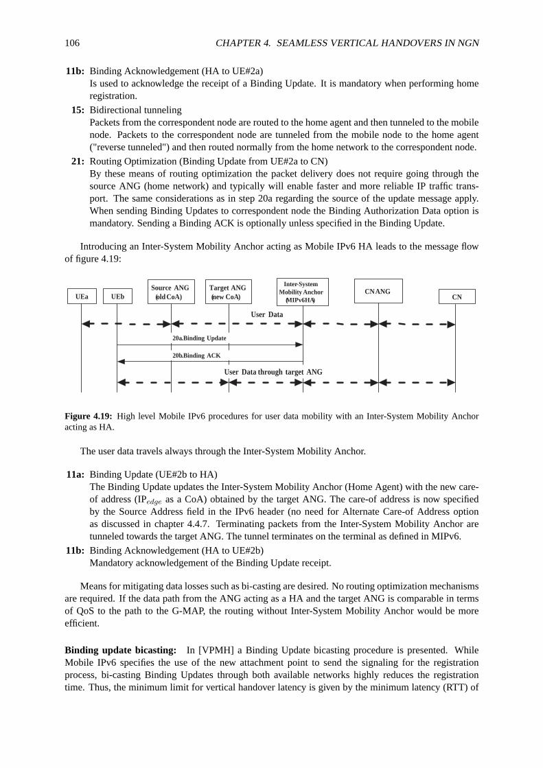
106 CHAPTER 4. SEAMLESS VERTICAL HANDOVERS IN NGN
11b: Binding Acknowledgement (HA to UE#2a)Is used to acknowledge the receipt of a Binding Update. It is mandatory when performing homeregistration.
15: Bidirectional tunnelingPackets from the correspondent node are routed to the home agent andthen tunneled to the mobilenode. Packets to the correspondent node are tunneled from the mobile node to the home agent("reverse tunneled") and then routed normally from the home network to thecorrespondent node.
21: Routing Optimization (Binding Update from UE#2a to CN)By these means of routing optimization the packet delivery does not requiregoing through thesource ANG (home network) and typically will enable faster and more reliableIP traffic trans-port. The same considerations as in step 20a regarding the source of the update message apply.When sending Binding Updates to correspondent node the Binding Authorization Data option ismandatory. Sending a Binding ACK is optionally unless specified in the Binding Update.
Introducing an Inter-System Mobility Anchor acting as Mobile IPv6 HA leadsto the message flowof figure 4.19:
CN UEa Source ANG
( old CoA) Target ANG ( new CoA )
20a . Binding Update
CN ANG
User Data
20b . Binding ACK
UEb
Inter -System Mobility Anchor
( MIPv6 HA )
User Data through target ANG
Figure 4.19: High level Mobile IPv6 procedures for user data mobility with an Inter-System Mobility Anchoracting as HA.
The user data travels always through the Inter-System Mobility Anchor.
11a: Binding Update (UE#2b to HA)The Binding Update updates the Inter-System Mobility Anchor (Home Agent) with the new care-of address (IPedge as a CoA) obtained by the target ANG. The care-of address is now specifiedby the Source Address field in the IPv6 header (no need for Alternate Care-of Address optionas discussed in chapter 4.4.7. Terminating packets from the Inter-System Mobility Anchor aretunneled towards the target ANG. The tunnel terminates on the terminal as defined in MIPv6.
11b: Binding Acknowledgement (HA to UE#2b)Mandatory acknowledgement of the Binding Update receipt.
Means for mitigating data losses such as bi-casting are desired. No routing optimization mechanismsare required. If the data path from the ANG acting as a HA and the target ANG is comparable in termsof QoS to the path to the G-MAP, the routing without Inter-System Mobility Anchor would be moreefficient.
Binding update bicasting: In [VPMH] a Binding Update bicasting procedure is presented. WhileMobile IPv6 specifies the use of the new attachment point to send the signalingfor the registrationprocess, bi-casting Binding Updates through both available networks highly reduces the registrationtime. Thus, the minimum limit for vertical handover latency is given by the minimum latency (RTT) of

4.4. MOBILITY MANAGEMENT FUNCTION (MMF) 107
available paths and not only by the latency of the new network, which can behigher than the currentnetwork (see figure 4.20).
Figure 4.20: Mobile IP BU bicasting mechanism reduces overall vertical handover latency with minimum over-head. Source [VPMH].
Network based Mobile IP
While the NETLMM [SKea06b] concept is still under standardization process in the IETF, a NETLMMprotocol could be used in an IMS provider based architecture with the samepotential benefits as whenused for local mobility (reduced signaling overhead on the radio interface, no host modifications, etc.).The same motivation as previously presented in chapter 4.4.2 for network based solutions applies.
[SWN05, SAL05, SMKP05, Sea05] are some of the proposed solutions that could be regarded as non-standard implementations of the NETLMM concept. [SGL05, SCS06] are alsonetwork based solutionsunder standardization that handle mobility based on MIPv6.
Considering these approaches, the architecture remains essentially the same. The UE is connectedat the source ANG and it is sending and receiving data via it. The G-MAP has a tunnel established withthe ANG. Upon handover request, the binding of IPedge to IPglobal is performed by the Inter-SystemMobility Anchor without involving the UE. The G-MAP is functionally a MIPv6 Home Agent. When athe mobile station enters the IPD domain for the first time, a G-MAP and a IPglobal gets assigned to thatmobile station. When the G-MAP intercepts a packet sent to the mobile station’s homeaddress (IPglobal),it tunnels the packet to the attached L-MAP of the mobile station. The encapsulated packet contains thefollowing:
Outer IPv6 Header: The source address is the LMAP’s address and the destination addressis the mo-bile node’s CoA (e.g. address of the MPA).
Inner IPv6 Header: The source address is the corresponding node’s address and the destination addressis the mobile node’s local address.
The access network entities and related procedures are not shown in figure 4.21 for brevity.
2: Reception of Handover RequestThe target ANG receives a handover trigger containing the context information of the handover.The steps required to establish the access network connectivity and the provision of resources arethe same as described in the general approach 4.4.7.
3: Binding Update (target ANG to G-MAP)The Mobile IPv6 Client in the target ANG sends a Binding Update to the HA with its own CoA(CoA of the target ANG) and sets the HoA of the MN received as part of the context informationat step 2.
4: Binding Acknowledgment (G-MAP to target ANG)Upon receiving the BU from the TAR, the G-MAP updates the binding cacheentry identified by
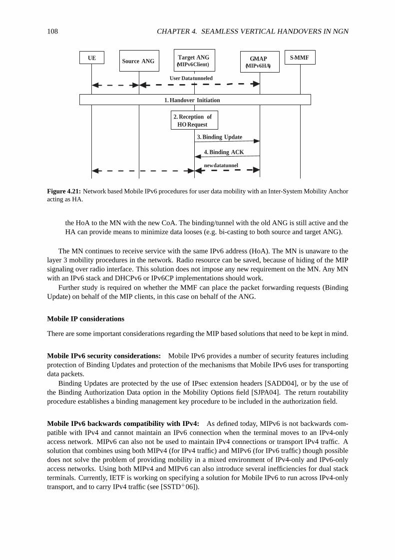
108 CHAPTER 4. SEAMLESS VERTICAL HANDOVERS IN NGN
new data tunnel
UE Source ANG Target ANG ( MIPv6 Client )
G - MAP ( MIPv6 HA )
S- MMF
1. Handover Initiation
2. Reception of HO Request
3. Binding Update
4. Binding ACK
User Data tunneled
Figure 4.21: Network based Mobile IPv6 procedures for user data mobilitywith an Inter-System Mobility Anchoracting as HA.
the HoA to the MN with the new CoA. The binding/tunnel with the old ANG is still activeand theHA can provide means to minimize data looses (e.g. bi-casting to both source andtarget ANG).
The MN continues to receive service with the same IPv6 address (HoA). The MN is unaware to thelayer 3 mobility procedures in the network. Radio resource can be saved,because of hiding of the MIPsignaling over radio interface. This solution does not impose any new requirement on the MN. Any MNwith an IPv6 stack and DHCPv6 or IPv6CP implementations should work.
Further study is required on whether the MMF can place the packet forwarding requests (BindingUpdate) on behalf of the MIP clients, in this case on behalf of the ANG.
Mobile IP considerations
There are some important considerations regarding the MIP based solutions that need to be kept in mind.
Mobile IPv6 security considerations: Mobile IPv6 provides a number of security features includingprotection of Binding Updates and protection of the mechanisms that Mobile IPv6 uses for transportingdata packets.
Binding Updates are protected by the use of IPsec extension headers [SADD04], or by the use ofthe Binding Authorization Data option in the Mobility Options field [SJPA04]. The return routabilityprocedure establishes a binding management key procedure to be included in the authorization field.
Mobile IPv6 backwards compatibility with IPv4: As defined today, MIPv6 is not backwards com-patible with IPv4 and cannot maintain an IPv6 connection when the terminal moves to an IPv4-onlyaccess network. MIPv6 can also not be used to maintain IPv4 connectionsor transport IPv4 traffic. Asolution that combines using both MIPv4 (for IPv4 traffic) and MIPv6 (for IPv6 traffic) though possibledoes not solve the problem of providing mobility in a mixed environment of IPv4-only and IPv6-onlyaccess networks. Using both MIPv4 and MIPv6 can also introduce several inefficiencies for dual stackterminals. Currently, IETF is working on specifying a solution for Mobile IPv6 to run across IPv4-onlytransport, and to carry IPv4 traffic (see [SSTD+06]).

4.4. MOBILITY MANAGEMENT FUNCTION (MMF) 109
Mobile Nodes with multiple interfaces multihoming capabilities in MIPv6: Devices with multipleinterfaces are foreseen to provide ubiquitous and fault-tolerant connection to communicating services,particularly on mobile nodes which are more exposed to failures or sudden lack of connectivity.
Proposed approaches regard each interface of the UE as an independent network path. This assump-tion lacks of multihoming capability. Multihoming allows bandwidth improvement and pathdiversityleveraging the overall path goodness. However, Mobile IPv6 currentlylacks support for such multi-homed nodes [MKLN04].
[SMWEN05] analyzes this gap in Mobile IP and intents to raise the discussion inorder to makesure that forthcoming solutions will address all the issues. In addition to this,a taxonomy to classifythe situations where a mobile node could be multihomed is proposed to remark the difficulties found onmultihomed mobile nodes operating Mobile IPv6.
Session adaptation through pre/post-SDP negotiation: Pure IP mobility mechanisms such as MIPv6does not provide methods for session adaptation. Regarding mobility between heterogeneous networks,important differences are expected between the QoS of the old and the newnetwork. A clever sessionadaptation is needed to maximize user’s QoE during and after the handover.
Considering info about new AN if new network capabilities are lower than oldfirst send re-INVITEwith adapted SDP and then carry on with the IP mobility mechanisms. Otherwise, session adaptationshould occur after IP mobility succeed. the first SDP offer sent by the MMF should only include codecswith whom the bandwidth constraint of the new AN are satisfied.
Routing optimization considerations: Routing Optimization in step 21 of figure 4.18 requires Mo-bile IPv6 support from the correspondent node. Requirement 8 in chapter 4.2 establishes that routingoptimization should be performed, even if the CN does not support the mobility management protocol.To deal with this issue, assuming the traffic from the CN is anchored througha corresponding ANG,the ANG could catch the Binding Update message towards the CN and update theroutes by his own.Then, the traffic from the CN would be redirected from the CN ANG to the target ANG in a transparentway to the CN. This idea is similar to the NETLMM approaches [SGL05, SCS06]that add client MIPfunctionality to the network and is another example of how signaling interception(compare with SIPinterception in chapter 4.4.6) at the edge points of a network can provide enhanced mobility functions.
Comparison of IP mobility strategies
Mobile IP solutions, though IP based and intended for commonality, have more and deeper impacts onexisting architectures, compared to solutions which only extend existing functionality. 3GPP SAE con-cludes in [Evo06] that 3GPP inter system handover solutions based on extensions of GTP (e.g. solutions)present practical advantages over those realizing the handover on IPlevel.
The key is if IETF solutions based on MIP will be mature enough to satisfy operator’s requirementsand outperform the capabilities of GTP based mobility. This enhancements imply the coordination ofmobility signaling and QoS signaling (currently handled in IETF nsis WG). Table4.6 gathers some ofthe pros and the cons of the proposed IP mobility mechanisms:
4.4.8 Evaluation
Due to the lack of available IMS environments for educational purposes, the comparison of signalingdiagrams is the only tool available to validate the proof-of-concept. signalingflows have been designedcomplaining the standards and specifications of the protocols.
A complete evaluation of the proposed schemes (e.g. Proxy MIP (PMIP) vs. GTP) is claimed andis left for future work. It requires the exhaustive identification of comparable factors to decide whichalternative fits better in available networks and upcoming access technologies. Factors to consider shouldinclude:

110 CHAPTER 4. SEAMLESS VERTICAL HANDOVERS IN NGN
Mobility approach Benefits Drawbacks
GTP
mature implementation in GPRS 3GPP specificQoS and AAA interaction built into terminalscharging and management per application tunnel (PDP)no tunnel over air interfaceregulatory issues (e.g. lawful inter-ception)
Mobile IPv6
IETF Standard with general scope tunnels all traffic (multihoming con-straints)
MIPv4 proofed by 3GPP2 built into terminalsIPv4-IPv6 interworkingadditional packet overhead (IP in IPencapsulation)
Network based MIP
no MIP support in the UE required Tunnels all trafficno MIP signaling over radio interfacework in progressno tunnel over air interface requirements at ANG
Inter AS anchor required
Table 4.6: Comparison of GTP, MIPv6 and PMIP based mobility.
• Performance (delay, jitter, overhead, power consumption, etc.)
• Complexity (required changes, implementation efforts, etc.)
• Costs (usually related with the complexity)
• Security threats
It is important to recall that the final implementation of the mobility scheme is constrained by al-ready deployed equipment, thus some mobility schemes can imply prohibitive costsdue to the requiredchanges.
In the following an analytical evaluation of SIP and IP based mobility schemes for vertical handoversin IMS based systems is presented. A deeper evaluation of proposed mechanisms and alternatives is leftfor future work and should include practical results.
SIP versus IP mobility strategies
SIP is the basis of the session management of the IMS and provides mechanisms enabling limited mo-bility. Thus, it would be desirable to use SIP to provide means of terminal and service mobility for allapplications. Using SIP for supporting mobility in the context of IMS presentsthe following benefits:
• Reuses IMS functionalities to reserve resources and ensure QoS. There is no need of new interfacesto access the PDF and AAAC mechanisms since the interaction of SIP with the IMSentities isalready defined.
• Provides inherent means of route optimization and improved performance for real-time servicesvia SIP signaling messages for address binding, registration, etc.
• Does not need a home IP address as MIP solutions.
• Provides mechanisms of session adaptation through SDP negotiation of the new session.
• Handles mobility at a semantic level (application layer mobility) above IP terminals allowing ses-sion transfers between terminals (MIP solutions offers only terminal mobility redirecting all IPtraffic).
But, SIP mobility mechanisms alone present also some limitations to overcome. SIP based mobilitymanagement:

4.5. CONCLUSION 111
• Is unable to move TCP sessions to new IP address.
• Lacks of seamless handover management.
• Yields large handoff delays.
• Requires SIP IMS version implementation at the UE.
Wedlund and Schulzrinne discuss in [WS99, SW00] the capabilities and problems associated withSIP and MIP mobility. Performance evaluations comparing SIP and MIP mobility mechanisms show thatSIP behaves better to support real time service mobility [WS99]. [PCT03] compares a pure SIP mobilityapproach versus a hybrid SIP/Mobile IP strategy and demonstrates how complementing SIP with otherIP mobility techniques provides the expected mobility support to every servicetype. An analysis of multiinterface mobility management using SIP and MIP has been proposed in [DKea05] and also concludesthat a smart combination of enhanced application and network mobility solutions outperforms the standalone mechanisms. Such a combination has been presented in this work as part of the SIP interceptionmechanism, where SIP signaling is used to trigger IP mobility mechanisms.
Table 4.7 gathers the benefits and drawbacks of SIP and IP based approaches for the mobility man-agement in IMS based networks.
Approach Benefits Drawbacks
SIP based
reuses IMS elements (QoS, AAA, charging)handoff delayoptimal route TCP supportsession adaptation correspondent node involvedimpacts on the infrastructure SIP IMS extensionsenhanced mobility services
IP based
keeps IP constant interaction with IMS (QoS, AAAC)TCP support additional elements required (HA, G-MAP)can be transparent to CN no session adaptationsupport for unmodified hosts means for route optimization
Table 4.7: Evaluation results of SIP vs.IP handover approaches
In the short term, supporting mobility at the application layer with SIP should be complementedwith other approaches that rely on network layer mobility protocols (e.g. MIP, NETLMM). Though SIP(with the required extensions and network architecture) may replace them inthe longer term. Such SIPenhancements require changes in both the network and the UE. SIP basedmobility mechanisms haveshown to be very powerful and capable of offering value added mobility services (e.g. based on MMFsimilar approaches). At the same time support for unmodified hosts is desiredin order to maximizethe number of potential UEs, therefore network based approaches have to be deployed. For an earlyIMS deployment network and IP based approaches seem to be the best option until next generationterminals and SIP based mobility approaches are available and mature enoughfor a telecom providerscale deployment.
4.5 Conclusion
None single all-in-one solution available. As suggested when considering the mobility requirements ofNGN the support of different mobility management protocols should be considered. The analysis ofthe different approaches conclude that enhancements are needed to achieve the convergence of differentprotocols and equipments. So, they key issue is an efficient interworking of the different approaches toachieve the always best connected paradigm.
Architectural enhancements are needed to implement IP mobility schemes. With these regards, theoutcomes of IETF are expected and early implementations of IP mobility protocolsshould proof their
112 CHAPTER 4. SEAMLESS VERTICAL HANDOVERS IN NGN
suitability for large scale communications networks. Huge efforts are still required to ensure a seamlessintegration in the IMS architecture. Efficient interworking with existing IMS mechanisms for resourcereservation or charging within the SIP signaling flows is a must to achieve seamless session continuityover heterogeneous networks.
Some kind of mobility management function upon the IMS control plane (application server likeimplementation) is required to smooth the different capabilities of heterogeneous networks. Informationservices, such as 802.21 MIH IS, are claimed to gather information (passive and active) of different net-work elements allowing the implementation of homogenous handoff triggers and the effective executionof mobility procedures.
The functionality of the MMF presented in this chapter points out how such a network based solutioncan assist moving nodes in an IMS environment. SIP possibilities haven beendiscussed and shortcom-ings regarding seamless handoff control have been addressed by theproposal of enhancements such asSIP extensions, signaling interception techniques and media resource functions. In addition to this, inno-vative SIP authentication mechanisms that reuse existing AAA mechanisms and afast IMS registrationscheme have been proposed.
SIP mobility mechanisms alone are not enough to maintain TCP connections activeduring IP ad-dress changes, therefore different IP mobility strategies have been studied to complement SIP mobilityschemes. The GPRS Tunneling Protocol and Mobile IPv6 (standard and network based) solutions havebeen described and compared. Future work should includes an exhaustive evaluation of the availablealternatives with regards to protocol performance, implementation complexity and associated costs. Cur-rent works in progress (e.g. NETLMM), proposed as technical alternatives, show the intense effortstowards the provision of session continuity regardless of the access network used.
Chapter 5
Conclusion and future work
This work has put light in the fixed-mobile convergence (FMC) concept, providing the technical chal-lenges behind the buzzy FMC word. The IP Multimedia Subsystem (IMS) is being regarded as the FMCenabler and has been selected to be the heart of next generation networks standardized by ETSI TISPANand ITU.
An analysis with these regards of the current release of the 3GPP’s IMShas confirmed the conver-gence capabilities of this network architecture. The separation of accessand service planes from thetransport network enables the re-use of core network components andmakes services independent fromthe access network. However, from the access independence definition to the practical adoption of non3GPP access networks, there is still much work to do.
The analysis has revealed required enhancements at the access networks and at the IMS itself. Inaddition to the constraints and issues from a real world deployment, the inherent differences of wirelessand wireline networks have to be accommodated. These include the provision of location information,terminal’s capabilities and different procedures for the resource management in the access networks.Additional issues include regulatory requirements that mandate support for emergency calls regardlessthe access type and lawful interception at both the signaling and the transport paths. Further work isneeded to adapt the SIP use in 3GPP e.g. timers, compression and optional support for SIP extensionssuch as Preconditions, Update or 100rel. Required enhancements to the access networks include servicebased policing (policy decision and enforcement points), translation of application level QoS description(SDP parameters) to IP bearer QoS parameters and link layer resource reservation mechanisms.
The close cooperation between the standardization bodies (3GPP, ETSI TISPAN, IETF, ITU, etc.)regarding the open issues shows the confidence of the telecom community in the principles of IMS, buthow and when the IMS will become a reality is still unclear.
Mobility management in heterogenous environments is a fundamental feature of NGN. Seamlessservice continuity across heterogenous access systems becomes a critical issue for IMS based networks.Actual release of IMS provides only limited mobility between different accessnetworks. The issues ofvertical handovers in such an environment have been identified. Seamless vertical handovers are verychallenging even in a small testbed environment without the constraints of IMS. The architecture andfunctions of the IMS add important issues to consider including the seamless mobility of the data andsignaling paths conforming standardized procedures to ensure charging continuity, policy commitmentor SIP call state control.
The envisioned enhancements to the mobility management in IMS include effective interworkingamong different levels (and layers) of mobility protocols and the provision of mechanisms for contexttransfers at IP layer or above. A vertical handover management function for seamless service continuity(not only for voice services) is being claimed. With this in mind, different steps (tasks) during a verticalhandover have been modeled, from the gathering context information to theexecution of the handovermechanisms passing by the initiation, evaluation and decision phases. Current state of the art in the dif-ferent areas have been reviewed (802.21 Media Independent Handover, Context Transfer Protocol, fuzzy
113

114 CHAPTER 5. CONCLUSION AND FUTURE WORK
logic, policy based networking, different layer mobility, etc.). Unfortunately, there is no straightforwardsolution that takes account of the multiplicity of mobility management requirements in heterogeneousnext generation networks.
Taking into consideration the identified requirements of a vertical handoverfunction for IMS, aMobility Management Function (MMF) has been proposed. The MMF can beregarded as an applicationlayer mobility management approach for NGN. The MMF can be deployed as ashared resource of IMSand additional services could be built upon the information and mobility functions offered by the MMF.A description of possible data structures describe how to collect useful information from different entitiesin an IMS based network. The MMF tracks ongoing user’s sessions andafter a mobility trigger, it startshandover mechanisms that take into account the requirements imposed by available access networksand ongoing session characteristics. SIP mechanisms proposed the use of the REFER method to movethe session to the new point of attachment. Problems regarding the seamlessness of the mobility havebeen addressed by the design of a SIP interception techniques, a transcoding service and a conferencingapproach. SIP limitation of keeping non real time connections alive (e.g. TCP) is one of the motivationsfor studying IP mobility strategies in an IMS based system. Proposed approaches include the use ofthe GPRS Tunneling Protocol and Mobile IP and the exchange of context information at IP level. Anetwork based solution has been shown to be very promising. In addition to this, innovative SIP basedmechanisms for terminal authentication and IMS registration have been proposed in an attempt to provideconverged AAA methods. Due to the lack of an IMS testbed, the proof-of-concept has been limited tothe description of the signaling flows.
The evaluation of the proposed alternatives to handle mobility has revealed that, in the short term,SIP mobility mechanisms should be complemented with other approaches that rely on network layermobility protocols. Though an enhanced version of SIP may replace them in the longer term, offering apowerful mobility management solution based on the application layer.
Future work has been already introduced during the work by including "further considerations" or"out of the scope" statements. Future work should start with the integration of a testbed IMS infrastruc-ture. One direction of future work should concentrate on the access networks and on the implementationof identified enhancements to make access networks and user devices IMScompliant. Another directionshould be the implementation of the concepts presented during the design of theMMF. Though the MMF,as described in this work, can be unrealistic for today real world deployments, many of the presentedconcepts should be further developed. A exhaustive practical evaluation of the proposed mechanismsfor handling vertical handovers in IMS based networks would mean a further step forward towards theenvisioned converged telecom world.
References
Standards and specifications— RFC —
[SADD04] J. Arkko, V. Devarapalli, and F. Dupont.Using ipsec to protect mobile ipv6 signaling between mobile nodes and home agents.RFC 3776 (Proposed Standard), June 2004.
[SBBC+98] S. Blake, D. Black, M. Carlson, E. Davies, Z. Wang, and W. Weiss.An Architecture for Differentiated Service.RFC 2475 (Informational), December 1998.Updated by RFC 3260.
[SCBSvW05] G. Camarillo, E. Burger, H. Schulzrinne, and A. van Wijk.Transcoding services invocation in the session initiation protocol (sip) using third party call control (3pcc).RFC 4117 (Informational), June 2005.
[SCLG+03] P. Calhoun, J. Loughney, E. Guttman, G. Zorn, and J. Arkko.Diameter Base Protocol.RFC 3588 (Proposed Standard), September 2003.
[SCMR02] G. Camarillo, W. Marshall, and J. Rosenberg.Integration of Resource Management and Session Initiation Protocol (SIP).RFC 3312 (Proposed Standard), October 2002.Updated by RFC 4032.
[SDBC+00] D. Durham, J. Boyle, R. Cohen, S. Herzog, R. Rajan, and A. Sastry.The COPS (Common Open Policy Service) Protocol.RFC 2748 (Proposed Standard), January 2000.Updated by RFC 4261.
[SDH98] S. Deering and R. Hinden.Internet protocol, version 6 ipv6 specification.RFC 2460 (Draft Standard), December 1998.
[SDra05] K. Drage.Update to rfc 3455: (private header (p-header) extensions to the session initiation protocol (sip) for the 3rd-
generation partnership project (3gpp). draft-drage-sipping-rfc3455bis-00. (work in progress).draft, Internet Engineering Task Force, October 2005.
[SFHBH+99] J. Franks, P. Hallam-Baker, J. Hostetler, S. Lawrence, P. Leach, A. Luotonen, and L. Stewart.HTTP Authentication: Basic and Digest Access Authentication.RFC 2617 (Draft Standard), June 1999.
[SHA98] D. Haskin and E. B. Allen.Ip version 6 over ppp.RFC 2472, Internet Engineering Task Force, December 1998.
[SHJ98] M. Handley and V. Jacobson.Sdp: Session description protocol.RFC 2327, Internet Engineering Task Force, April 1998.
[SIET05] IETF.Seamoby wg.http://www.ietf.org/html.charters/seamoby-charter.html., jul 2005.
[SJPA04] D. Johnson, C. Perkins, and J. Arkko.Mobility Support in IPv6.RFC 3775 (Proposed Standard), June 2004.
[SKem02] J. Kempf.Problem description: Reasons for performing context transfers between nodes in an IP access network.
115
116 CHAPTER 5. CONCLUSION AND FUTURE WORK
RFC 3374, Internet Engineering Task Force, September 2002.
[SKoo05] R. Koodli.Fast Handovers for Mobile IPv6.RFC 4068 (Experimental), July 2005.
[SLMS05] P. Leach, M. Mealling, and R. Salz.A universally unique identifier (uuid) urn namespace.RFC 4122, Internet Engineering Task Force, July 2005.
[SLNPK05] J. Loughney, M. Nakhjiri, C. Perkins, and R. Koodli.Context transfer protocol (cxtp).RFC 4067, Internet Engineering Task Force, July 2005.
[SLSC+05] M. Liebsch, A. Singh, H. Chaskar, D. Funato, and E. Shim.Candidate access router discovery (card).RFC 4066 (Experimental), July 2005.
[SMar03] W. Marshall.Private Session Initiation Protocol (SIP) Extensions for Media Authorization.Technical Report 3313, IETF, January 2003.
[SMBD04] R. Mahy, B. Biggs, and R. Dean.The session initiation protocol (sip) “replaces” header.RFC 3891 (Proposed Standard), September 2004.
[SMK04] J. Manner and M. Kojo.Mobility Related Terminology.Technical Report 3753, IETF, June 2004.
[SMP04] R. Mahy and D. Petrie.The session initiation protocol (sip) “join” header.RFC 3911 (Proposed Standard), October 2004.
[SPer02] C. Perkins.IP Mobility Support for IPv4.RFC 3344 (Proposed Standard), August 2002.
[SPet04] J. Peterson.Session initiation protocol (sip) authenticated identity body (aib) format.RFC 3893 (Proposed Standard), September 2004.
[SRam04] B. Ramsdell.Secure/multipurpose internet mail extensions (s/mime) version 3.1 message specification.RFC 3851 (Proposed Standard), July 2004.
[SRKS04] J. Rosenberg, P. Kyzivat, and H. Schulzrinne.Indicating user agent capabilities in the session initiation protocol (SIP).RFC 3840, Internet Engineering Task Force, August 2004.
[SRPSC04] J. Rosenberg, J. Peterson, H. Schulzrinne, and G. Camarillo.Best Current Practices for Third Party Call Control (3pcc) in the Session Initiation Protocol (SIP).RFC 3725 (Best Current Practice), April 2004.
[SRS02a] J. Rosenberg and H. Schulzrinne.An offer/answer model with session description protocol (SDP).RFC 3264, Internet Engineering Task Force, June 2002.
[SRS02b] J. Rosenberg and H. Schulzrinne.Reliability of provisional responses in session initiation protocol (SIP).RFC 3262, Internet Engineering Task Force, June 2002.
[SRSC+02] J. Rosenberg, H. Schulzrinne, G. Camarillo, A. R. Johnston, J. Peterson, R. Sparks, M. Handley, and E. Schooler.Sip: Session initiation protocol.RFC 3261, Internet Engineering Task Force, June 2002.
[SRVC01] E. Rosen, A. Viswanathan, and R. Callon.Multiprotocol Label Switching Architecture.RFC 3031 (Proposed Standard), January 2001.
[SRWRS00] C. Rigney, S. Willens, A. Rubens, and W. Simpson.Remote authentication dial in user service (RADIUS).RFC 2865, Internet Engineering Task Force, June 2000.
[SSch02] H. Schulzrinne.Dynamic host configuration protocol (dhcp-for-ipv4) option for session initiation protocol (SIP) servers.RFC 3361, Internet Engineering Task Force, August 2002.
117
[SSH99] P. Srisuresh and M. Holdrege.IP Network Address Translator (NAT) Terminology and Considerations.RFC 2663 (Informational), August 1999.
[SSpa03] R. Sparks.The session initiation protocol (sip) refer method.RFC 3515, Internet Engineering Task Force, April 2003.
[SSV03] H. Schulzrinne and B. Volz.Dynamic host configuration protocol (dhcpv6) options for session initiation protocol (SIP) servers.RFC 3319, Internet Engineering Task Force, July 2003.
[SSXM+00] R. Stewart, Q. Xie, K. Morneault, C. Sharp, H. Schwarzbauer, T.Taylor, I. Rytina, M. Kalla, L. Zhang, andV. Paxson.
Stream Control Transmission Protocol.RFC 2960 (Proposed Standard), October 2000.Updated by RFC 3309.
[STN98] S. Thomson and T. Narten.Ipv6 stateless address autoconfiguration.RFC 2462, Internet Engineering Task Force, December 1998.
— Internet-Drafts —
[SACG98] A.Valko, A. Campbell, and J. Gomez.Cellular ip. draft-valko-cellularip-00 (work in progress).draft, Internet Engineering Task Force, November 1998.
[SAL05] I. Akiyoshi and M. Liebsch.Netlmm protocol. draft-akiyoshi-netlmm-protocol-00 (work in progress).draft, Internet Engineering Task Force, October 2005.
[SCB05] G. Camarillo and G. Blanco.The session initiation protocol (sip) p-user-database private-header(p-header), November 2005.
[SCS06] K. Chowdhury and A. Singh.Network based layer 3 connectivity and mobility management for ipv6. draft-chowdhury-netmip6-00 (work in
progress).draft, Internet Engineering Task Force, February 2006.
[SDea05] A. Dutta and et. al.Problem statement for heterogeneous handover, October 2005.
[SDFHD06] G. Daley, S. Faccin, E. Hepworth, and S. Das.Requirements for a handover information service. draft-faccin-mih-infoserv-02 (work in progress).draft 2, Internet Engineering Task Force, March 2006.
[Sea05] G. Giaretta et al.Network-based localized mobility management (netlmm) with distributed anchor route. draft-giaretta-netlmm-
protocol-00 (work in progress).draft, Internet Engineering Task Force, October 2005.
[SGL05] S. Gundavelli and K. Leung.Localized mobility management using proxy mobile ipv6. draft-gundavelli-netlmm-mip6-proxy-00 (work in
progress).draft, Internet Engineering Task Force, November 2005.
[SHFV06] E. Hepworth, G. Daley S. Faccin, and G. Vivek.Media independent handovers: Problem statement. draft-hepworth-mipshop-mih-problem-statement-01 (work
in progress).draft 1, Internet Engineering Task Force, March 2006.
[SKea06a] J. Kempf and et. al.Requirements and gap analysis for ip local mobility, January 2006.
[SKea06b] J. Kempf and et al.Requirements and gap analysis for ip local mobility. draft-draft-kempf-netlmm-nohost-req-01 (work in progress).draft, Internet Engineering Task Force, January 2006.
[SMKP05] M.Parthasarathy, R. Koodli, and B. Patil.Network-based fast handovers for local mobility (nflm). draft-mohan-nflm-proto-00 (work in progress).draft, Internet Engineering Task Force, October 2005.
[SMos04] R. Moskowitz.Hip: Host identity protocol. draft-ietf-hip-base-04 (work in progress).draft 4, Internet Engineering Task Force, October 2004.
[SMWEN05] N. Montavont, R. Wakikawa, T. Ernst, and C. Ng.

118 CHAPTER 5. CONCLUSION AND FUTURE WORK
Analysis of multihoming in mobile ipv6. draft-montavont-mobileip-multihoming-pb-statement-05 (work inprogress).
draft, Internet Engineering Task Force, October 2005.
[SRea05] J. Rosenberg and et. al.Request authorization through dialog identification in the session initiation protocol (sip), December 2005.
[SRPT+00] R. Ramjee, T. La Porta, S. Thuel, K. Varadhan, and L. Salgarelli.Ip micro-mobility support using hawaii. draft-ietf-mobileip-hawaii-01 (work in progress).draft, Internet Engineering Task Force, July 2000.
[SRT06] M. Riegel and M. Tuexen.Mobile sctp. draft-riegel-tuexen-mobile-sctp-06 (work in progress).draft 6, Internet Engineering Task Force, March 2006.
[SSSTK06] R. Shacham, H. Schulzrinne, S. Thakolsri, and W. Kellerer.Session initiation protocol (sip) session mobility, February 2006.
[SSTD+06] H. Soliman, G. Tsirtsis, V. Deverapalli, J. Kempf, and et al.Mobile ipv6 support for dual stack hosts and routers (dsmipv6). draft-ietf-mip6-nemo-v4traversal-01 (work in
progress).draft, Internet Engineering Task Force, March 2006.
[SWN05] E. Wood and K. Nishida.Edge mobility protocol (emp). draft-draft-wood-netlmm-emp-base-00 (work in progress).draft, Internet Engineering Task Force, October 2005.
3GPP[3gp06a] 3rd generation partnership project.
http://www.3gpp.org/About/about.htm, may 2006.
[3gp06b] 3rd generation partnership project 2.http://www.3gpp2.org/Public_html/Misc/AboutHome.cfm, may 2006.
[Evo06] 3GPP System Architecture Evolution.Report on technical options and conclusions (release 7) version v0.10.0.Technical Report TS 23.882, 3GPP, jan 2006.
[NT05a] 3GPP Technical Specification Group Core Network and Terminals.Ip multimedia call control protocol based on session initiation protocol (sip) and session description protocol
(sdp) (release 7) version v7.1.1.Technical Report TS 24.229, 3GPP, oct 2005.
[NT05b] 3GPP Technical Specification Group Core Network and Terminals.Policy control over go interface (release 6) version 6.5.0.Technical Report TS 29.207, 3GPP, sep 2005.
[NT05c] 3GPP Technical Specification Group Core Network and Terminals.signaling flows for the ip multimedia call control based on session initiation protocol (sip) and session descrip-
tion protocol (sdp); stage 3 version 5.13.0.Technical Report TS 24.228, 3GPP, aug 2005.
[NT06] 3GPP Technical Specification Group Core Network and Terminals.Gprs tunnelling protocol (gtp) across the gn and gp interface (release 7) version 7.1.0.Technical Report TS 29.060, 3GPP, mar 2006.
[SA05a] 3GPP Technical Specification Group Service and System Aspects.Ip multimedia subsystem (ims) charging; version 6.4.0.Technical report, 3GPP, dec 2005.
[SA05b] 3GPP Technical Specification Group Service and System Aspects.Service requirements for the all-ip network (aipn); stage 1 (release 7) version 7.0.0.Technical Report TS 22.258, 3GPP, dec 2005.
[SA05c] 3GPP Technical Specification Group Services and System Aspects.Ip multimedia subsystem (ims); stage 2; version 7.1.0.Technical Report TS 23.228, 3GPP, oct 2005.
[SA05d] 3GPP Technical Specification Group Services and System Aspects.System to wireless local area network (wlan) interworking; system description (release 6) version 6.6.0.Technical Report TS 23.234, 3GPP, sep 2005.
[SA05e] Technical Specification Group Services and System Aspects.Voice call continuity between cs and ims study (release 7) version 7.0.0.Technical Report TS 23.806, 3GPP, dec 2005.

119
[SA06a] 3GPP Technical Specification Group Services and System Aspects.System to wireles local area network (wlan) interworking; wlan user equipment (wlan ue) to network protocols;
stage 3 (release 7) version 7.1.0.Technical Report TS 24.234, 3GPP, mar 2006.
[SA06b] 3GPP Technical Specification Group Services and System Aspects.Vocabulary for 3gpp specifications (release 7) version v7.1.0.Technical Report TS 21.905, 3GPP, mar 2006.
ETSI[ETS98] ETSI.
Final report of etsi fmc ad hoc group. european telecommunications standards institute. sophia-antipolis., 1998.
[tis06] Telecoms & internet converged services & protocols for advanced networks.http://portal.etsi.org/tispan/, may 2006.
ITU[IT04] ITU-T.
Principles and requirements for convergence of fixed and existing imt-2000 systems.Technical Report Q.1761, ITU-T, 2004.
[Q.204] ITU Q.2/SSG.Technical report on mobility management.Technical Report TSGS25(04)0538, ITU, 2004.
IEEE[Soc05] IEEE Computer Society.
P802.21/d00.01 draft ieee standard for local and metropolitan area networks: Media independent handoverservices, July 2005.
Publications[Ame05] 3G Americas.
Convergence: An outlook on device, service, network and technologytrends, July 2005.
[aSB04] J. Indulska adn S. Balasubramaniam.Context-aware vertical handovers between wlan and 3g networks.In Proceedings of the 2004 IEEE Fifty-Ninth Vehicular Technology Conference, 2004.
[AXM04] I.F. Akyildiz, J. Xie, and S. Mohanty.A survey of mobility management in next-generation all-ip-based wirelesssystems.[IEEE] Commun. Mag., 40:16 – 28, Aug. 2004.
[Bar05] D. Baron.Sip.edu workshop. sip basics.http://www.internet2.edu/sip.edu/200507-workshop/, jul 2005.
[BB94] A. Bakre and B. Badrinath.I-TCP: Indirect TCP for Mobile Hosts.Technical Report DCS-TR-314, Rutgers University, October 1994.
[Bea98] E. Brewer and et al.A network architecture for heterogeneous mobile computing, 1998.
[BI04] S. Balasubramaniam and J. Indulska.Vertical handover supporting pervasive computing in future wireless networks.Computer Communications, 27(8):708–719, 2004.
[BS97] K. Brown and S. Singh.M-TCP: TCP for Mobile Cellular Networks.In Proceedings of the ACM SIGCOMM CCR, pages 19–43, 1997.
[cab06] Cable television laboratories.http://cablelabs.com/about/, may 2006.
[CFS05] M. L. Cristofano, A. G. Forte, and H. Schulzrinne.Generic models for mobility management in next generation networks.Technical Report CUCS-031-05, Columbia Computer Science, 2005.

120 CHAPTER 5. CONCLUSION AND FUTURE WORK
[CGK+02] A. T. Campbell, J. Gomez, S. Kim, Z. Turanyi, C-Y. Wan, and A. Valko.Comparison of ip micro-mobility protocols.IEEE Wireless Communications Magazine, 9(1), February 2002.
[CGZZ04] C.Guo, Z. Guo, Q. Zhang, and W. Zhu.A seamless and proactive end-to-end mobility solution for roaming across heterogeneous wireless networks.IEEE JOURNAL ON SELECTED AREAS IN COMMUNICATIONS, 22(5):834–847, jun 2004.
[CP04] N. Crespi and Q. M. Phan.Extending gtp protocol to support seamless handover between umts andwlan access network.In CDMA International Conference, CIC 2004, page 358, October 2004.
[CSHe01] P.M.L. Chan, R.E. Sheriff, Y.F. Hu, and et.al.Mobility management incorporating fuzzy logic for heterogeneous a ip environment.IEEE Communications Magazine, 39:42 – 51, 2001.
[Cum05] J. Cumming.Session border control in ims - an analysis of the requirements for session border control in ims networks.Whitepaper - Data Connection, 2005.
[DKea05] A. Dutta, B. Kim, and T. Zhang et al.Experimental analysis of multi interface mobility management with sip and mip.In Wireless Networks, Communications and Mobile Computing, 2005 International Conference on, pages 1301–
1306. ISBN: 0-7803-9305-8 Digital Object Identifier: 10.1109/WIRLES.2005.1549600, jun 2005.
[DMC+03] A. Dutta, S. Madhanie, W. Chen, O. Altintas, and H. Schulzrinne.Optimized fast-handoff schemes for application layer mobility management.SIGMOBILE Mob. Comput. Commun. Rev., 7(1):17–19, 2003.
[DOea] A. Dutta, Y. Ohba, and H. Schulzrinne et al.Seamless handover across heterogeneous networks - an ieee 802.21 centric approach.
[DVC+01] A. Dutta, F. Vakil, J. Chen, M. Tauil, S. Baba, N. Nakajima, and H. Schulzrinne.Application layer mobility management scheme for wireless internet, 2001.
[EN02] M. Endler and V. Nagamuta.General approaches for implementing seamless handover.In POMC ’02: Proceedings of the second ACM international workshop on Principles of mobile computing,
pages 17–24, New York, NY, USA, 2002. ACM Press.
[EUR99] EURESCOM.P809-gi mobility in the broadband environment based on in evolution, June 1999.
[FHL05] X. Fu, D. Hogrefe, and D. Le.A review of mobility support paradigms for the internet.Technical Report IFI-TB-2005-01, Institute for Informatics, University of Göttingen, January 2005.
[FILea05] A: Fresa, G.i Iacovoni, M. Longo, and et al.A testbed for experimentation of innovative services in the b3g framework.In TRIDENTCOM, pages 110–119, 2005.
[GJ03] E. Gustafsson and A. Jonsson.Always best connected.IEEE Wireless Communications Magazine, feb:49–55, 2003.
[GOC+04] I. Ganchev, M. O’Droma, H. Chaouchi, I. Armuelles, M. Siebert,and N. Houssos.Requirements for an integrated system and service 4g architecture.In Proceedings of IEEE Semiannual Vehicular Technology Conference (VTC2004-Spring), page 5, Milan, Italy,
May 2004.
[Gup] D. Vivek Gupta.Ieee 802.21 a generalized model for link layer triggers.
[HDS03] P. Hsieh, A. Dutta, and H. Schulzrinne.Application layer mobility proxy for real-time communication.In World Wireless Congress, 3G Wireless, San Francisco, May 2003. Delson, Delson.
[HNH05] A. Hasswa, N. Nasser, and H. Hassanein.Generic vertical handoff decision function for heterogeneous wireless networks.IFIP Conference on Wireless and Optical Communications, pages 239–243, March 2005.
[Jen05] C. Jennings.Instance identifiers for sip user agents. draft-jennings-sipping-instance-id-01 (work in progress).draft 1, Internet Engineering Task Force, July 2005.
[KH02] A. Kist and R. Harris.Sip signaling delay in 3gpp.In INTERWORKING, pages 211–222, 2002.
121
[KMT05] K. Knightson, N. Morita, and T. Towle.Ngn architecture: Generic principles, functional architecture, and implementation.IEEE Communications Magazine, pages 49–56, Oct 2005.
[Kor] J.i Korhonen.Vertical handover related work elsewhere.http://www.cs.hut.fi/ pmrg/Education/2005_vho_sc/pdf/VHO_SC_Vertical_handover_related_work_elsewhere.pdf.
[LCHW05] Y. Lin, M. Chang, M. Hsu, and L. Wu.One-pass gprs and ims authentication procedure for umts.IEEE Journal on Selected Areas in Communications, 23(6):1233 – 1239, 2005.
[MK02] A. Majlesi and B. H. Khalaj.An adaptive fuzzy logic based handoff algorithm for hybrid networks.In Proc. of 6th International Conference on Signal Processing, volume 2, pages 1223 – 1228, Aug. 2002.
[MKLN04] N. Montavont, M. Kassi-Lahlou, and T. Noel.Description and evaluation of mobile ipv6 for multiple interfaces, March 2004.
[MMP03] K. Murray, R. Mathur, and D. Pesch.Intelligent access and mobility management in heterogeneous wireless networks using policy.In ISICT ’03: Proceedings of the 1st international symposium on Information and communication technologies,
pages 181–186. Trinity College Dublin, 2003.
[MP01] K. Murray and D. Pesch.Neural network based adaptive radio resource management for gsm andis136 evolution.Vehicular Technology Conference, 2001. VTC 2001 Fall. IEEE VTS 54th, 4:2108–2112, 2001.
[MPW03] P. Mendes, C. Prehofer, and Q. Wei.Context management with programmable mobile networks, 2003.
[MWK05] T. Magedanz, D. Witaszek, and K. Knuettel.The ims playground @ fokus - an open testbed for next generation network multimedia services.In TRIDENTCOM, pages 2–11, 2005.
[MYLR04] L. Ma, F. Yu, V.C.M. Leung, and T. Randhawa.A new method to support umts/wlan vertical handover using sctp.IEEE Wireless Communications, 11(4):44–51, August 2004.
[MYP00] J. Makela, M. Ylianttila, and K. Pahlavan.Handoff decision in multi-service networks.In Proc. of 11th IEEE International Symposium on Personal, Indoor andMobile Radio Communications
(PIMRC’00), volume 1, pages 655 – 659, London, UK, Sep. 2000.
[MZ04] J McNair and F. Zhu.Vertical handoffs in fourth-generation multinetwork environments.Wireless Communications, IEEE, 11, Issue: 3:8–15, June 2004.
[NDDS03] N. Nakajima, A. Dutta, S. Das, and H. Schulzrinne.Handoff delay analysis and measurement for sip based mobility in ipv6.IEEE ICC, May 2003.
[oGMCT00] First International Conference on 3G Mobile CommunicationTechnologies, editor.Mobility management for the support of handover within a heterogeneousmobile environment. Orange PCS,
2000.
[oma] Open mobile alliance (oma).http://www.openmobilealliance.org/.
[Pat04] B. Patil.Ip mobility ensures seamless roaming.Electronic Engineering Times-Asia, jun 2004.
[PCT03] C. Politis, K.A. Chew, and R. Tafazolli.Mobility support using sip.In Vehicular Technology Conference, 2003. VTC 2003-Spring. The 57thIEEE Semiannual, pages 2500–2504,
2003.
[PMKN04] M. Poikselka, G. Mayer, H. Khartabil, and A. Niemi.The IMS: IP Multimedia Concepts and Services in the Mobile Domain.Wiley, 1st edition, June 2004.
[Pro01] GLOBECOM 2001 Proceeding, editor.End-to-End SIP Based Real Time Application Adaptation During UnplannedVertical Handovers, 2001.
[Pro02] 3Gwireless’2002 Proceeding, editor.Multimedia SIP sessions in a Mobile Heterogeneous Access Environment, 2002.

122 CHAPTER 5. CONCLUSION AND FUTURE WORK
[QFM+03] Q.Wei, K. Farkas, P. Mendes, C. Prehofer, B. Plattner, and N. Nafisi.Context-aware handover based on active network technology.In IWAN, pages 280–291, 2003.
[SHS01] J. Sun, D. Howie, and J. Sauvola.Mobility management techniques for the next-generation wireless networks.In Proc. SPIE Vol. 4586, p. 155-166, Wireless and Mobile Communications, Hequan Wu; Jari Vaario; Eds.,
pages 155–166, oct 2001.
[SK98] M. Stemm and R. H. Katz.Vertical handoffs in wireless overlay networks.ACM Mobile Networks and Applications, 3(4):335 – 350, 1998.
[SS] J. Sun and J. Sauvola.On fundamental concept of mobility for mobile communications.
[SW00] H. Schulzrinne and E. Wedlund.Application-layer mobility using sip.SIGMOBILE Mob. Comput. Commun. Rev., 4(3):47–57, 2000.
[TC03] D. Trossen and H. Chaskar.Seamless mobile applications across heterogeneous internet access.In Communications, 2003. ICC ’03. IEEE International Conference on, volume 2, pages 908– 912, May 2003.
[TTL99] L. Taylor, R. Titmuss, and C. Lebre.The challenges of seamless handover in future mobile multimedia networks.IEEE Personal Communications, 6(2):32–37, April 1999.
[uma06] Unlicensed mobile access (uma).http://www.umatechnology.org/, may 2006.
[VCP04] P. Vidales, R. Chakravorty, and C. Policroniades.Proton: A policy-based solution for future 4g devices, 2004.
[VPMH] Pablo Vidales, Leo Patanapongpibul, Glenford Mapp, and AndyHopper.Experiences with heterogeneous wireless networks, unveiling the challenges.
[Wan] Qi Wang.Towards a complete solution to mobility management for next-generation wireless system.
[WS99] E. Wedlund and H. Schulzrinne.Mobility support using sip.In WOWMOM ’99: Proceedings of the 2nd ACM international workshop on Wireless mobile multimedia, pages
76–82, New York, NY, USA, 1999. ACM Press.
[XKW02] W. Xing, H. Karl, and A. Wolisz.M-sctp: Design and prototypical implementation of an end-to-end mobility concept, 2002.
[Yla05] M. Ylanttila.Vertical handoff and mobility - System architecture and transition analysis.PhD thesis, University of Oulu, 2005.
[YOI05] M. Yabusaki, T. Okagawa, and K. Imai.Mobility management in all-ip mobile network: end-to-end intelligence or network intelligence?IEEE Communications Magazine, 43(12):16–24, 2005.
[ZT01] C. Zhang and V. Tsaoussidis.TCP-Real: Improving Real-time Capabilities of TCP over Heterogeneous Networks.In Proceedings of the 11th IEEE/ACM NOSSDAV, June 2001.