technologies former koppers co., inc. site newport, … koppers co., inc. site newport, delaware....
TRANSCRIPT

i Evaluation of the Applicabilityof In-Situ Thermal Remediation«
Technologies
CD
in
ooce
Former Koppers Co., Inc. SiteNewport, Delaware

Agenda LO
COOC.
Introduction- Purpose- Technical Evaluation Approach- Overview of Findings- Desired Outcomes
BackgroundStatus of RI/FSSite Conceptual ModelTechnical Evaluation- Resistance Heating- In-Situ Thermal Desorption (ISTD)- Steam Injection
Conclusions

Purpose and ApproachCNJ
-3"LO
:^>
Satisfy EPA's request to critically evaluate applicable insitu thermal remediation technologies for the FormerKoppers Newport Superfund Site
•
•
Present our evaluation of applicable in-situ thermal "remediation technologies ;
Technical Evaluation Approach- Technology Overview- Status of Technology- Challenges- Applicability to the Site- Conclusion •
: CO•«
Evaluation Process
Performed a thorough evaluation of the status of in-situ thermal remediation technologies
in
coor
Evaluated the applicability of in-situ thermal |remediation technologies to the site based onjsite-specific factors "
9
*K
Determined if and how in-situ thermal remediationtechnologies should be applied at the site

Overview of Findings LO
COoc
There are challenges and certain site- ;
specific factors that would preclude the useof in-situ thermal remediation technologies atthis site
The site-specific factors are discussed indetail later in the presentation
V
**
Desired OutcomesGain a better understanding of applicable in-situ thermalremediation technologies and their requirements for-success
V
Improve our understanding of the site conceptual model
Gain a better understanding of the site-specific factorsthat may influence and/or limit the successful applicationof in-situ thermal remediation technologies /
Work toward an agreement with the EPA regarding theapplicability of in-situ thermal remediation technologiesfor the site
or

Background5
Operational History- Wood treating site that operated from about 1929 to 1971 . "f- Used creosote/coal tar to preserve railroad ties, telephone poles, and
other wood products
Site Setting- 300 acre site (approx)- Upland areas comprise ~ 160 acres- Wetlands comprise -140 acres- Bordered on the north by high-speed railroad lines- Bordered on the east by the former DuPont Holly Run Plant and
Christina River- Bordered on the south and west by White Clay Creek and Hershety Run- Depth to groundwater ~ 10 feet below ground surface

Site Setting
2OOC 2000
ooor

t-:
Site Setting - Former Process Area CO("••o
-3-t.0

Site Setting - Fire Pond\-T>
CO
Status of RI/FSoCO-:±LO
CO
Rl approved Fall 2002 ">
Draft FS submitted September 1999 •
USEPA requested evaluation of in-situ thermal remediation :technologies in comment letter dated November 2001
•
Supplemental data collection activities performed in Fall 2002/Winter2003 to support FS ;:- Soil boring program to further delineate the fine-grained, low permeability
layer in the Upper Potomac Fmt.- Sediment sampling program to further delineate extent of impacts;in
Hershey Run ;
Revised FS to be submitted in Spring 2003

••.,
Site Conceptual Model 1>r!
ty
• Site Layout ;
• Hydrogeology- Stratigraphy- Hydraulic gradients and flow rates
• NAPL Distribution- Surface and shallow subsurface (vadose zone)- Below water table
• Groundwater Quality and Use ;
CO-:*•LO. - , ! —
COre
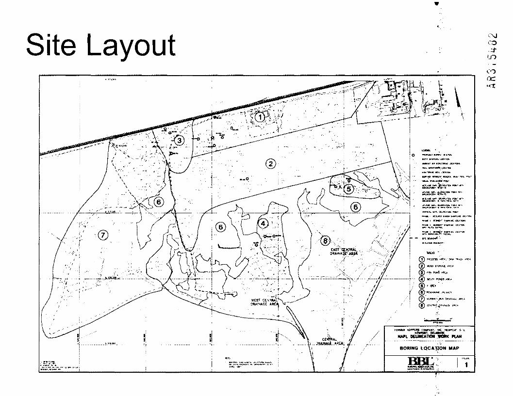
Site Layout
COMPANY, 1*C. MtWt^fT S-IOIIT. aeuftftMT
NAPL DEUNEATKM VOftK PLAN
C\J
CO.:±LO

Hydrogeology COI*
(D
Upper Hydrostratigraphic Unit- Includes fill, Quaternary deposits, and Columbia Formation soils- Thickness ranges from about 10 to 50 ft- Distributed lenses of sand, silt, and clay- Heterogeneous- Depth to water table - 10 feet below the ground- Kv*~5x10- 5 t o4x10 - 7
Fine-grained, low permeability unit- Classified as clayey silt / silty clay based on geotechnical analyses- Distinctive, reddish-pink color- Low activity based on Atterberg Limits (low shrink-swell capacity)- Kv*~5x io - 8
- Uniform distribution- Thickness ranges from about 0.5 - 35 feet
Lower Hydrostratigraphic Unit- Includes Potomac Formation soils- Thickness not determined (believed to be greater than 50 feet)- Distributed lenses of gravel, sand, silt, and clay- Kv* not measured
"Units in cm/sec

HydrogeologyCO
ID
COen
n:z::rJE. ____
QEHERAUXED CROSS 8CCTION DO

Hydrogeology
inCO..3-I.O
CO
r UO'.i'G-t'-.C A i - . L ..CC
j- SCrtUM-U INItWVAi1 INFTRRCD KYDRoUtlCf nwAmt^r aiPtcnow
870 u>»ojnL- ftJilK• '
A'
MMCDIAL WVCSTKATI«M.REPORT
GENERALIZED CROSS*6ECTION A-A
3-2

Visual interpretation of soil boring logs SB-607 and SPG-1 as presented in Rl
CO
SILTY FINE-CL1ARSE SANDAND GRAVFL
C L A Y E Y MEDIUMTD FINE SAND
COARSE TD FINE SAND
WELL-SORTED GRAVEL
SANDY CLAY
SILTY COARSE TD FINE SAND
FINE SANDY SILT
SILTY FINE SAND
C L A Y E Y S ILTY SAND
Return
Hydrogeology CO
\W.TXANOS BOUNQ*t
ALWfNl AlB UONI'ORt^C IOC*T10MS
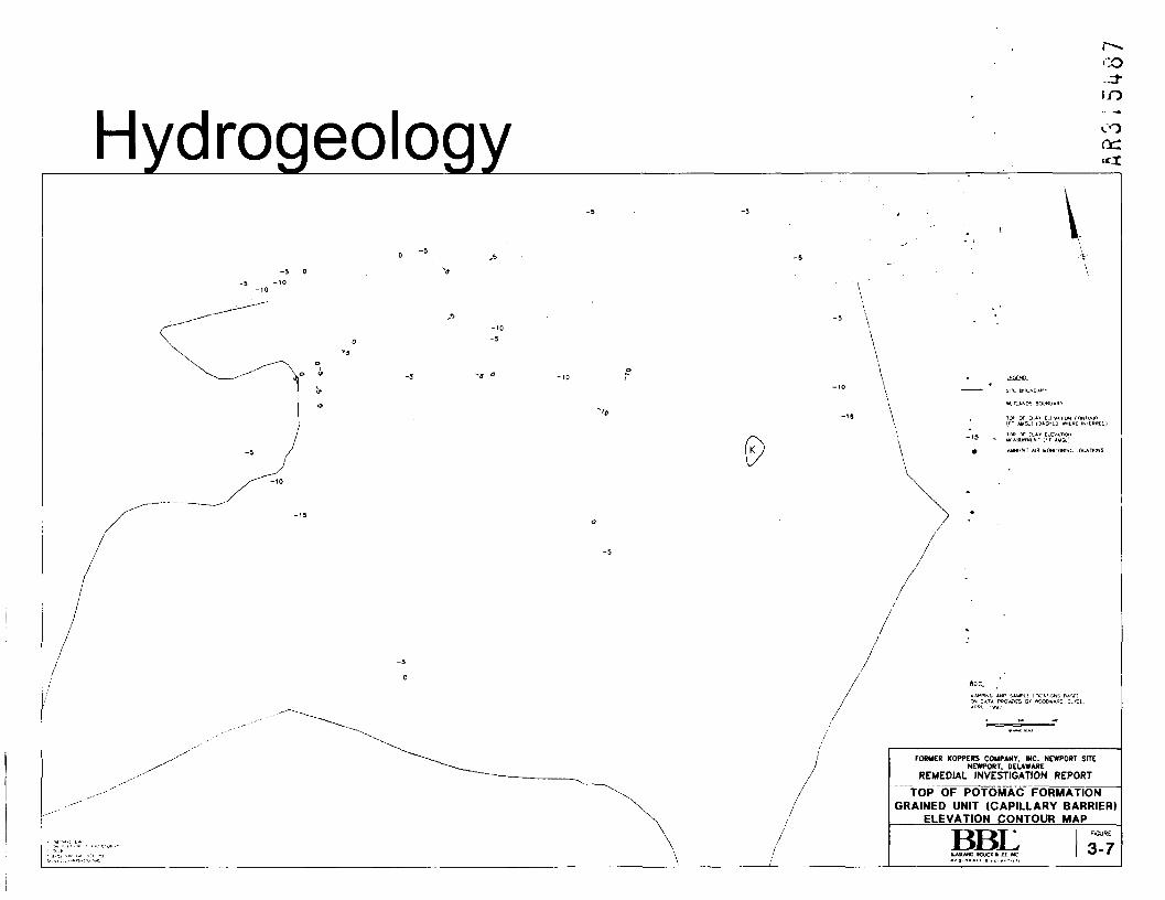
FORMER KOPPERS COMPANY, INC. NEWPORT SITENEWPORT, DELAWARE
REMEDIAL INVESTIGATION REPORT
TOP OF POTOMAC FORMATIONGRAINED UNIT (CAPILLARY BARRIER)
ELEVATION CONTOUR MAP
BBI:LASLAND. BOUCK ft LEE. INC
3-7
HydrogeologyCO
(XL
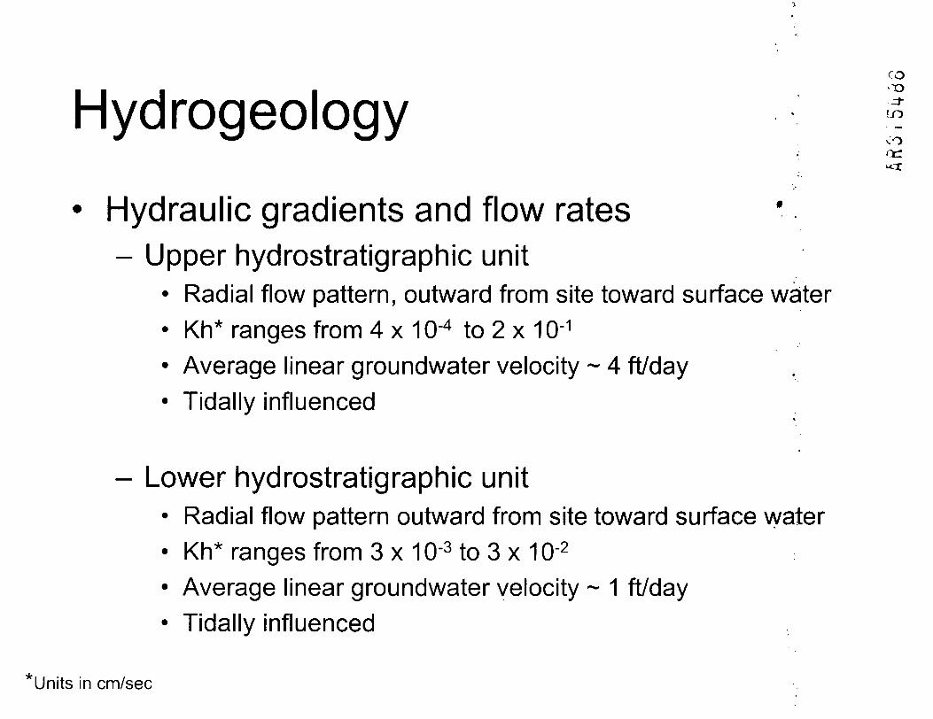
Hydraulic gradients and flow rates- Upper hydrostratigraphic unit
• Radial flow pattern, outward from site toward surface water• Kh* ranges from 4 x 10~4 to 2 x 10~1
• Average linear groundwater velocity - 4 ft/day• Tidally influenced
- Lower hydrostratigraphic unit• Radial flow pattern outward from site toward surface water• Kh* ranges from 3 x 10'3 to 3 x 10'2
• Average linear groundwater velocity ~ 1 ft/day• Tidally influenced
* Units in cm/sec
cr»
Hydrogeologyin
CO(XL
:c^5•'ilryc^::* TM
.'•70*>1'«M^^jr
i—'•^-v';
v—
V
y -t
,T. t5£XAWARE
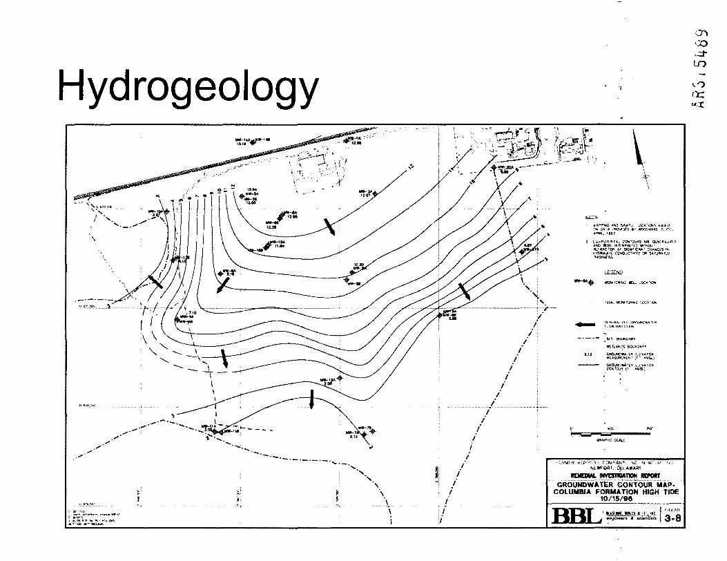
MVC5HQAHOM RCPOffTGROUKDWATER CONTOUR MAP-
COLUMBIA FORMATION HIGH TIDE10/15/96
BBL 3-8

Hydrogeology COoc
~>C^ V *4-- Hi?\ ;i~i--:i •
.ND IfeKL IHtl.Hi<ftt'!l3 WM.j-*ACr>{>, Ar Sttwf'Cwf ctW*Ui£ CO*>JC7(VTTY C*
•
LtSi-ND
I»O(ITGROUNOWATER CONTOUR MAP-
POTOMAC FORMATION HIGH TIDE1C
BBL 3-12

NAPL Characterization/Distributionen
CO
Surface soils/vadose zone £J
- NAPL Types:
• Weathered, brittle, granular, and immobile (behaves like a solid). Generally found in surface soils andsome subsurface soils above the water table
• NAPL Blebs and Thin Seams: Present in very small quantities in samples; likely at or below residual saturationand therefore immobile and immobilizable
- Observations: Extensively visible in large areas at or near the ground surface
Below the water table (> 10 feet)
- NAPL Types:
• NAPL Blebs and Thin Seams: Present in very small quantities in samples; likely at or below residualsaturation and therefore immobile and immobilizable
Saturated NAPL. Present throughout pore spaces in a sample; potentially mobilizable
• Pooled NAPL: Present as a continuous phase in the soil; mobilizable
- Observations:
• NAPL was initially present at two shallow MWs (MW-2A and MW-8A) during Rl activities
NAPL was not measured at these same two MWs in Fall 2002 (sheen only)
NAPL DistributionOsJT>-J-in
co
V S
' rt ~ ' ""V" ~ ~
f \ •\ \ v* ^ \
.A-A iv . » \
\ ;
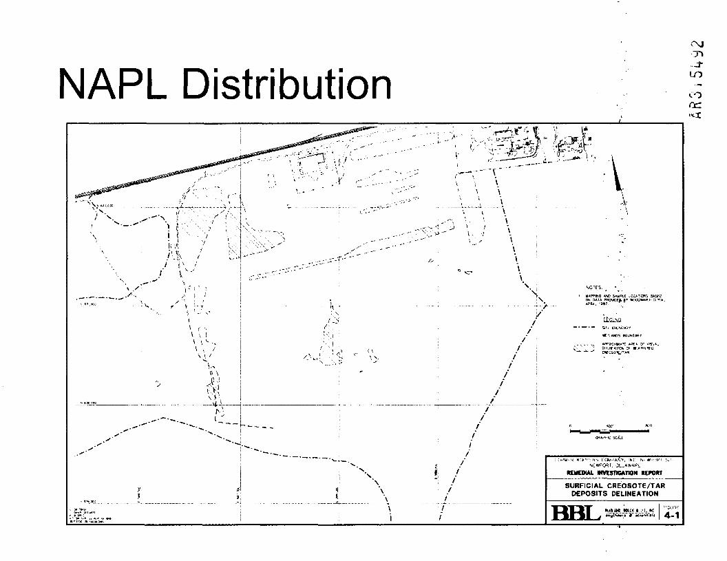
l. OUAWARL
REMEDIAL INVESTIGATION RETORT
SURFICIAL CREOSOTE/TARDEPOSITS DELINEATION
BBL 4-1
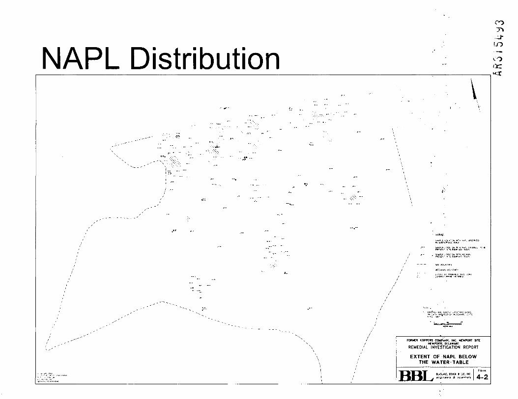
NAPL DistributionCOT»
LO
V
FOftuTR KOPPEKS COMPANY, INC. NCWPOftT SITE
NEWPORT, DELAWAREREMEDIAL INVESTIGATION REPORT
EXTENT OF NAPL BELOWTHE WATER'TABLE
BBL BUSLAHQ, BOUCX & J.L IHC.
4-2

Groundwater Quality and UseTV
•J-
to
co
Groundwater Quality (5 sampling events)- Impact limited to upper hydrostatigraphic unit- Lower hydrostratigraphic unit not impacted- Impact is not horizontally extensive; limited to "halo" around some NAPL areas- BTEX and other VOCs detected in samples from MW-2A at levels >^\ ppm- Total PAHs detected in samples from MW-2A at levels >10 ppm (NAPL blebs
potentially present in samples)- Low levels of BTEX and total PAHs (<50 ppb) detected in some other wells
Groundwater Use- Groundwater in upper hydrostratigraphic unit not used for potable water •- Groundwater in lower hydrostratigraphic unit is used for potable water in some areas- There are no drinking water wells at the site- There are no current potential human health risks based on groundwater exposure
pathways identified in the EPA-approved risk assessment

Groundwater Quality LO
COor:
i W ]*?,:**! •'•**_' *'*T I*7?rioc'"T 14 Tsc" =?* ' " Iw"
'. 3ft AAAR?
REMEDIAL INVESTIGATION REPORTiy« 4yia j »/»»/!> ia^>
SUMMARY ANALYTICAL RESULTSUPPtR HYOBOSTRATKJRAPHIC UNIT (COLUMBIA
FORMATIOK AND OUAtERNAMV DEPOSITS)

Technical Evaluation
UD
co
Resistance heating- 6 phase heating- 3 phase heating
In-situ thermal desorption (ISTD)
Steam injection

Technical Evaluation Approach4'
• Technology Overview• Status of Technology• Challenges• Applicability to the Site• Conclusion
in
COQC.

CO
in
coor
RESISTANCE HEATING
- 6 Phase Heating- 3 Phase Heating

Technology Overviewin
COor
Uses electromagnetic waves to heat up soil andgroundwater
Electrodes are required to transmit energy
All subsurface features receive energy
Large subsurface features (tank, foundations,etc.) act as energy sinks

Technology Overview:6 c|) Heating
Applied as stand-alone technology
6 electrodes in hexagon around neutral vent well
Hexagon diameter typically -20-45'
Typical objective was to boil water/NAPL, volatilizeNAPL, or drive via steam stripping
Requires above-ground vapor and water treatmentsystems
LO
CO

Technology Overview:3 4 > Heating
. Primarily used as component ofDynamic Underground Stripping (DUS)
. Provides technique to accelerate heatingof low permeability layers during steaming
O10inco

Status Of Technology
CNi
oin
COex:
Commercially available technology
Multiple field pilot tests have beencompleted (chlorinated solvent sites)
Several full-scale applications havedemonstrated advantages anddisadvantages

ICN Pharmaceuticals Site,Portland OR
COo10\n
COor
December 2002 EPA/TIO Conference
Presentation by Jennifer Sutter, Oregon DEQ
120'x80'Area;60ftbgs
TCE, daughter products, benzene, toluene

Heating Electrode - Portland, ORO10'•.n
CO

Well Field Layout - Portland, ORLO
in
COaz-cr

Status Of Technology
• Lower cost approaches being evaluated
• Costs typically not competitive with steaminjection
•
• Focusing on lowering energy requirements byjust heating to reduce viscosity or enhancebiodegradation
• Would still require collection of fluids
\nID
CO

ChallengesoinLO
COrt:
Failures of electrodes and wells experienceddue to localized overheating
Water infiltration used to prevent "dryout" andcontrol overheating
Difficult to balance water infiltration and heatingrequirements
Larger treatment areas require more than onehexagon
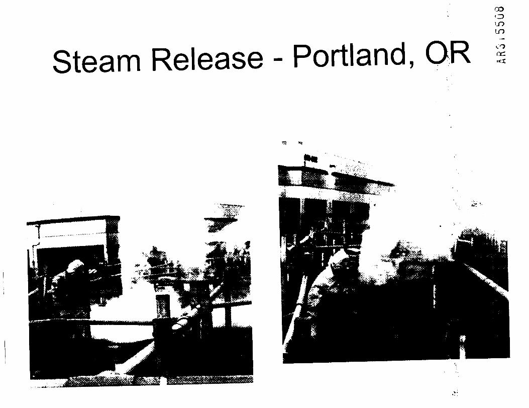
Steam Release - Portland, OR
COoLOLO
CO(XL
«*

Applicability to SiteSix Phase Heating
Power supply: High power lines would have to be routed to site and transformerinstalled. Would likely require phased implementation
• Size of Impacted Area: Would require multiple hexagons, creating interference andchanneling between adjacent cells
Heterogeneities: Low and high permeabilities will exacerbate uneven heating andalso prevent uniform distribution of water used to control overheating
Creosote: Never successfully applied for creosote; DNAPL will be difficult to fullyrecover and may migrate into underlying layer
Three Phase Heating*
Primarily applicable as component of steam injection»* .
Further evaluated w/ steam injection
LOLO
CO

Conclusions - 6 PhaseLOLO
CO
Electrical Resistance Heating
6 phase heating is not feasible as a stand-aloneremedy given the types of soil andcontaminants present at the site and overalllimitations for effectiveness of the technology
3-phase heating is further evaluated ascomplement to steam injection

LOLO
CO
In Situ Thermal Desorption

Technology Overview• Patented technology licensed to single vendor
CXJ
LOLO
COoc:
The process uses thermal conduction to heat soil and groundwaterto vaporize contaminants
Electric elements are placed in steel wells and operated at >1400°F(750°C)
Heating progresses through soil laterally from each thermal well
Heating is continued until vaporization of interstitial water andcontaminants is complete
Vapors are extracted by SVE and treated via abovegroundequipment (RTO/GAC)
Technology OverviewApplied as stand-alone technology
Typically applied in vadose zone for treatment ofrecalcitrant contaminants (e.g., PCBs)
Thermal wells placed on 5-7 foot centers
Demonstrations and full scale implementation performedfrom 1996 to present
Typical power requirements are 350 Watts per linear footof heater element
CO
LOLO
COcc

Technology OverviewVapor Pressure of Contaminants
inin
cocc.uct
300 C 200 C

LO
LOLO
COCfL
TechnologyOverview
ThermModel
Simulation
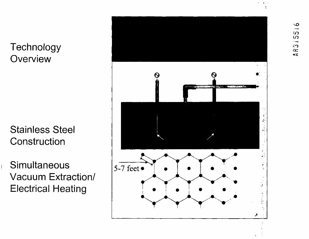
TechnologyOverview
Stainless SteelConstruction
SimultaneousVacuum Extraction/Electrical Heating
LOLO
COcc«cr
5-7 feet

Technology StatusThermal Well Project History
• Missouri Electric Works/BADCAT Demonstration- 12 wells; 2-12 feet BGS; PCBs
• Portland, IN - Industrial Manufacturing Facility100 wells; 2-19 feet BGS; Solvents
• *Eugene, OR - Bulk Storage Facility700 wells; 2-11 feet BGS; Petroleum
• Centerville Beach, CA - Former Naval Facility- - 60 wells; 5-16 feet BGS; PCBs
• *Alhambra, CA Former Wood Treating (ongoing)- ~ 600 wells; 10-90 feet BGS; PCP, PAHs
r-.
LOLO
COQC.•ct

Eugene, OR - Full Scale ProjectAerial Photograph
CO
inin
CO
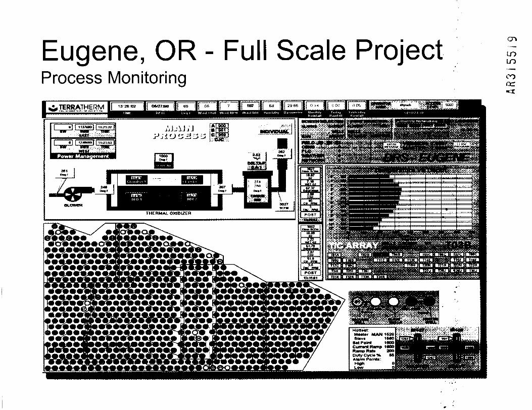
Eugene, OR - Full Scale ProjectProcess Monitoring
cr»
LOLO
COcc.•tr
^TCRRATHERM li
2ti IO - o f j
5V.VAVAV.•v.v.v.
Hott*«t:Muttr MAN 1626Slav* 1S«OLJi2*i
8M Point 1600Currant Ramp 1«OORamp Mate 2OOOutyCycl*<KAlarm PoinU:Hlgti 0Lew
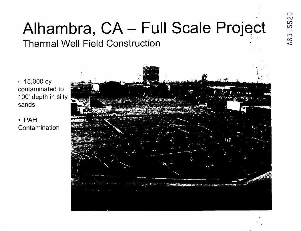
Alhambra, CA- Full Scale PThermal Well Field Construction
OCNJLO1.0
CO
• 15,000 cycontaminated to100' depth in siltysands
• PAHContamination

ChallengesC\JLOin
COcc.
Failures of elements experienced due to overheating
Groundwater recharge (horizontal and vertical)
Permitting/operation of air quality control equipment
Maintaining subsurface vacuum levels
Larger areas require significant electric power forsimultaneous operation

Applicability to Newport SiteCNJC\JLOLO
COcc
Dewatering of treatment areas will be necessary to achieve sufficienttemperatures to vaporize contaminants
Groundwater recharge will limit ability to dewater upper hydrostratigraphic unitdue to K
Surface insulation and seals will be required to achieve elevated temperaturesand recovery of contaminants, thereby impacting existing vegetation
Significant impacted material will be generated from thermal well installations(5-7 ft spacing)
Permit substantive requirements will be necessary for operation of above-ground treatment AQC equipment
Power requirements will exceed current resources available

ConclusionsCOc\jLOLO
COcc«cr
ISTD will not be able to attain effective treatment without completelyde-watering the Columbia Formation, which is improbable giyeh thepermeability and structure of site soils, as well as the proximityofsurface water features
Dewatering the Columbia Formation could result in increasing thedownward hydraulic gradient and/or desiccation and fracturing of thefine-grained unit, which increases the risk of mobilizing NAPLdownward into the Potomac formation
Ground water/surface water control requirements are virtually'insurmountable
Wetland habitat destruction required in some areas
CNJ
LOLO
COoc
Steam Injection
(Steam Enhanced Extraction)(Dynamic Underground Stripping)

Technology OverviewLOCNJLOLO
COcc•cr
Two main patents- UC Berkeley- Lawrence Livermore
Heat up subsurface via injection of steam
Derived from thermally-enhanced oil recovery
Efficient way to apply energy to subsurface

Well Layout for Steam Injection
03
C/3
T3(73d)
o
CO
V/" V^
v/* v/* vy
N-/" vy vy
Injection well
Extraction well
CNJLOLO
COCC•CC

Technology Overview:Typical Application ;
• Steam injected via stainless steel wells
• Fluid recovery from extraction wells using dual-phase pumps
• Distance between wells - same as depth toground surface
• Steam "chest" evolves spherically from injectionwell if no other influences
r-.C\JLOLO
CO

Process Flow for Steam InjectionCOC\JLOLO
CO
Watersofteners Fresh water supply/treated
recirculated water
Stack gas exhaust toatmosphere
Off-gaspolisher
Stack
Steam to pressureregulator stations and
well-field
Power toprocessequipmentand net
-*-
Heat exchanger/condenser
De-airator Air b|ovver
PumP treatment Q]

Technology Overview:Multiple Recovery Mechanisms
Contaminants removed via volatilization,distillation, steam displacement, andbiodegradation
Mechanisms different for different contaminantsand lithologies
Most effective in zones with K > 103 cm/s
Other technologies used in conjunction withsteam (3-(() Heating)
enC\JLOLO
COcc

Status of TechnologyOCOLOLO
CO
Proven technology via pilot tests
1 field-scale, full-size application (Visalia)
Several vendors w/ experience and licenses- SteamTech- IWR
- SCE w/ CH2M Hill
- ERM?

Status of TechnologyCOLOLO
COor«cr
Effectiveness is function of site-specificfeatures
Bench tests don't simulate site-specificeffectiveness
Field pilot tests required for optimization

Case Study at VisaliaCMCOinin
oocc
Visalia Pole Yard; Visalia, CA
Creosote DNAPL
Target zone was 700' x 300' x 120'bgs
Layered geology

COCOLOLO
CO
Phase I Steam Injection Cross Section
. 'Ac-LI . Ml 11 1 <lll
Grounkiraiter Flux 3 gpdj'ff2
10 Source: Eaker, 2000.

Phase II Steam Injection Cross-Section
COLOLO
COQC
14 Source: Eaker, 2000.
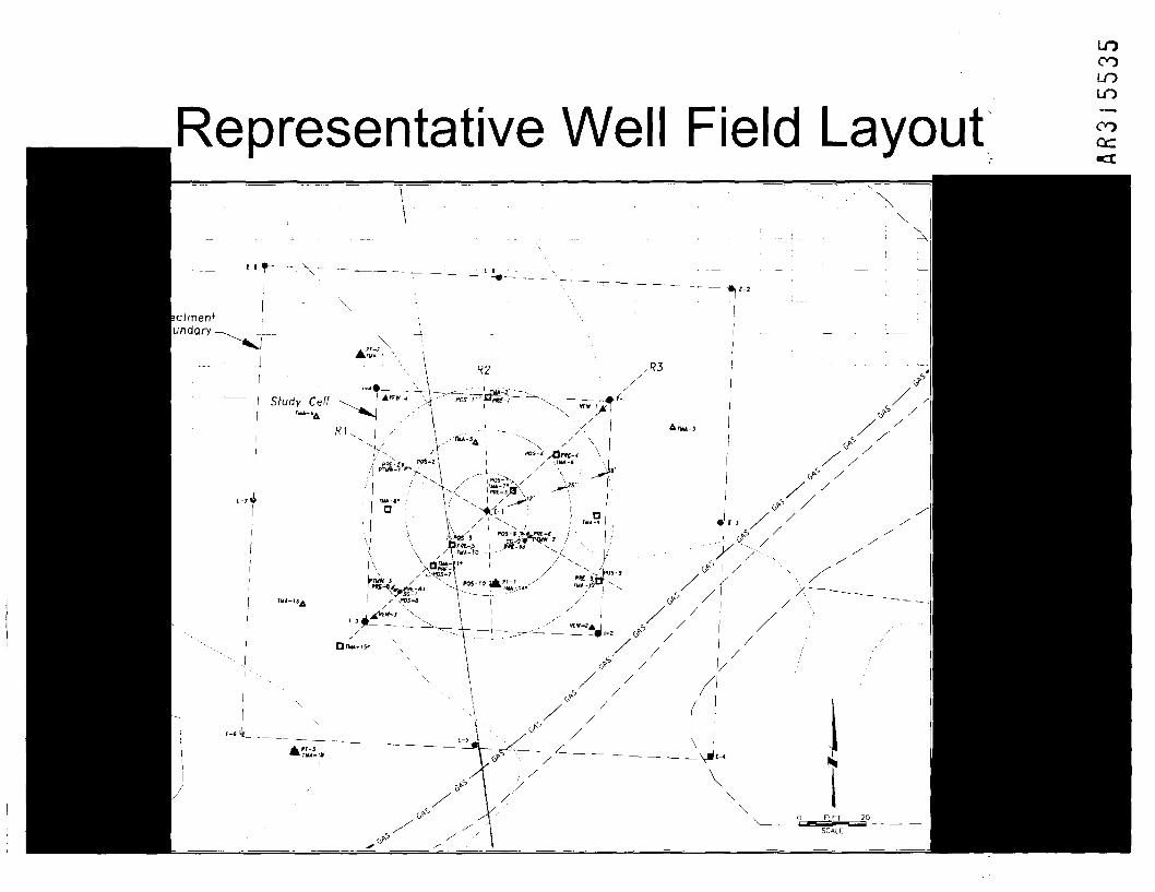
Representative Well Field Layout
LOCOLOLO
COOC
e-J t- —_.^ _ -__ _

Piping & Instrumentation DiagramFreshwater
supply '
Water
softenersWS1
51
FRT.P
Vaporfrom
centralwell
Vap »ors ^fr°welm Isoufend *sideE ,extw fracVJaeion is *
»—
uidextrs acti *~~froon
m welou|s ^side *
Liquid from centrextraction well
C
P L ( \i' Propane fuel' PROP1 j
T.P V. JI n , 0^
• o3 FRP i,team genera
1Brinewaste
Liquic
Heat exchanger/ sepcondenser L
HX1
PoDint-r hKI 'H " SG-1
DAI ^ ::'::Air dryer Air blower I;!;
Am (—} K :;|:/vapor Vacuum pump 1 i/ ;:;:
arator > • • "•""vsi (C^i Tr :•::
^~"X* v/1: Primarv 1, /v \ V2 ^ f^Af.1 »
T V_V T ^TT^- ^ y^7 va water
Heat exchanger/condensor V-
HX2 ^
Heatexchanger
HX4
L3-To NAPL
P* ' ' 1 ^ J T'P FRT,T |f« gjjj^=^ Air VS V9 ~ V10 I>
y AD2 FRT.T.P f^> VS §
vs lillsl^ Liquid /vapor K**S«SPS«| Q^
:•:•:'] T P I Prmary;•:•:• i .H.L ^Ar?
,,__>; PT.L-
: LII
.,.„ . -^ * HHHH " HRT.LS
FT.LS :•:•
L3-water
Heatexchanger
!l HX3
U //\^\ L2
T ^J '
•!•"• Breakout ..u.u/:;j;: tank separator 2
VDDO- ^ L5 L6 ^^
^jW® « FT.LS Bnnewas,e FRT,LS j:i
" and blowdown ,I;I.
T.L- g)— * W3ter Wate
'Gra'vi'.y' ^'.^Rflparator 1 „ ....
tack gas exhaust toatmosphere
1VS f V12or | Steam to 4
*
injection wells • •
• k ''-FR.T.P • ._
I-2 • 1
a *S< Steam FR'T'P
FR.T.Pvy ,.3
Pressure • ^ *regulator FR.T.P
1-4 -•m B» '
1 V.1 r-K var,r,r«.r, FR.T.P ,.
gi VS ' atmosphere
sherVC3
^
i
r holdincank
.. --
^BNAPL holding
tank
L7r^, , . — 1\ To Unocal=* _ Jl . _ ' — i/ disposal wells
rKI ,Lb •
L
;
GS1 * Monitoring/sample point P Pressure
FINAL FR Flow rate T TemPeratijre
FT Flow totalizer VS Vapor sampling point
FRT Flow rate and totalizer LS Liquid sampling point
COLOLO
COQC.

Challenges - Design%
• Design of injection rates / injection wellspacing / injection depth
COLOLO
CO
Design of recovery system, wells andtreatment train
Cost-effective pilot test

Challenges:Ideal Features for Steam Injection
Easy access to utilities and monitoring
Moderate permeability or layer-cake geology withcontaminants in high K zone
*
Limited heterogeneities
Impermeable cover at ground surface
Contaminants that are highly volatile, low viscosity,single component, or highly biodegradable bythermotropic bacteria
COCOLOLO
CO

COLOLO
COCC
Applicability to Newport Site
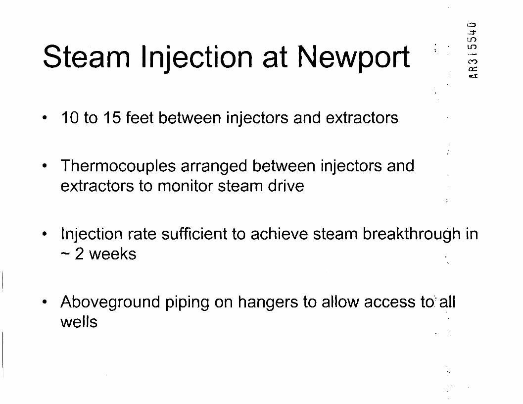
Steam Injection at NewportCD-U-LOLO
CO(DC
10 to 15 feet between injectors and extractors
Thermocouples arranged between injectors andextractors to monitor steam drive
Injection rate sufficient to achieve steam breakthrough in~ 2 weeks
Aboveground piping on hangers to allow access to allwells

Newport Application (Cont'd)
• Mount equipment on skids to facilitatesteam generation and fluidseparation/treatment
LOLO
COOC.
Approx 20 skids may be required
NAPL, water, and vapor effluent streamsrequire separate cooling and treatment

Factors Influencing Success«
• Ground surface- No barrier creates concern for steam venting- Drilling and piping will denude vegetation
CNJ-3-LOLO
COor
Shallow application- Steam may channel or vent along injection
well to surface- Injection pressures could cause fracturing

Factors Influencing Success \%
• Heterogeneities- Difficult to control migration of contaminants- Heating will be uneven- Limit recovery effectiveness
CO
LO
COor
ncreased potential migration into lowpermeability units- Lower geologic unit- Low permeability zones within steam zone

Factors Influencing Success
• Contaminant^
- High viscosity- Low volatility- Key recovery mechanism will be distillation- Recovery will require long sustained
application
IDin
COcc.•ct

ConclusionsSteam Injection Is Not Feasible Because:
Shallow depth without ground cover would allow short-circuiting of injectedsteam and steam venting at surface. Steam would potentially over-rideintended DNAPL.
Creosote recovery via distillation would require long-term application ofsteam.
Injection pressures would likely cause fracturing, with unintended steamand contaminant migration. Steam front could not be monitored.
Heterogeneities would limit heating and limit recovery of low permeabilityzones. Contaminants would be mobilized from high-K zones to low-Kzones. Recovery well operation could not be optimized. Low K zones arenot continuous layers and thus not applicable for three phase heating".
Large size of impacted area would require phased implementation ofsteam treatment cells; phased program has never been successfully tried.
LO-3-LOLO
COQC•o: