technology and market foresight • strategic research ... · vtt working papers 133 vtt creates...
TRANSCRIPT

VTT WORKING PAPERS 133VTT CREATES BUSINESS FROM TECHNOLOGY�Technology�and�market�foresight�•�Strategic�research�•�Product�and�service�development�•�IPR�and�licensing�•�Assessments,�testing,�inspection,�certification�•�Technology�and�innovation�management�•�Technology�partnership
•�•�•��VTT�WO
RKIN
G�PA
PERS�133�����B
ENTO
mA
P:�SuR
VEy�Of�B
ENTO
NITE�A
Nd
�TuN
NEl�B
Ac
KfIll�KNO
WlEd
GE
ISBN 978-951-38-7194-9 (URL: http://www.vtt.fi/publications/index.jsp)ISSN 1459-7683 (URL: http://www.vtt.fi/publications/index.jsp)
Elisa Rautioaho & Leena Korkiala-Tanttu
Bentomap: Survey of bentonite and tunnel backfill knowledge
State-of-the-art
VTT Working Papers
117 Paula Järvinen, Kai Puolamäki, Pekka Siltanen & Markus Ylikerälä. Visual analytics. Final report. 2009. 45 p. + app. 3 p.
118 Anna-Maija Hietajärvi, Erno Salmela, Ari Happonen & Ville Könönen. Kysyntä- ja toimitusketjun synkronointi metalli- ja konepajateollisuudessa Suomessa. Haastattelututkimus. 2009. 33 s. + liitt. 3 s.
119 Timo Korhonen & Simo Hostikka. Fire Dynamics Simulator with Evacuation: FDS+Evac. Technical Reference and User’s Guide. 2009. 91 p.
120 Veikko Kekkonen & Göran Koreneff. Euroopan yhdentyvät sähkömarkkinat ja markkinahinnan muodostuminen Suomen näkökulmasta. 2009. 80 s.
121 Rinat Abdurafikov. Russian electricity market. Current state and perspectives. 2009. 77 p. + app. 10 p.
122 Bettina Lemström, Juha Kiviluoma, Hannele Holttinen & Lasse Peltonen. Impact of wind power on regional power balance and transfer. 2009. 43 p.
123 Juha Forström. Euroopan kaasunhankinnan malli. 2009. 80 s.124 Jyrki Tervo, Antti Manninen, Risto Ilola & Hannu Hänninen. State-of-the-art of
Thermoelectric Materials Processing, Properties and Applications. 2009. 29 p.125 Salla Lind, Björn Johansson, Johan Stahre, Cecilia Berlin, Åsa Fasth, Juhani Heilala,
Kaj Helin, Sauli Kiviranta, Boris Krassi, Jari Montonen, Hannele Tonteri, Saija Vatanen & Juhani Viitaniemi. SIMTER. A Joint Simulation Tool for Production Development. 2009. 49 p.
126 Mikko Metso. NoTA L_INdown Layer Implementation in FGPA Design results. 2009. 20 p.
127 Marika Lanne & Ville Ojanen. Teollisen palveluliiketoiminnan menestystekijät ja yhteistyösuhteen hallinta - Fleet asset management - hankkeen työraportti 1. 2009. 65 s. + liitt. 12 s.
128 Alternative fuels with heavy-duty engines and vehicles. VTT’s contribution. 2009. 106 p. + app. 8 p.
129 Stephen Fox. Generative production systems for sustainable product greation. 2009. 101 p.
130 Jukka Hemilä, Jyri Pötry & Kai Häkkinen. Tuotannonohjaus ja tietojärjestelmät: kokemuksia sekä kehittämisperiaatteita. 2009. 37 s.
131 Ilkka Hannula. Hydrogen production via thermal gasification of biomass in near-to-medium term. 2009. 41 p.
132 Hannele Holttinen & Anders Stenberg. Tuulivoiman tuotantotilastot. Vuosiraportti 2008. 2009. 49 s. + liitt. 8 s.
133 Elisa Rautioaho & Leena Korkiala-Tanttu. Bentomap: Survey of bentonite and tunnel backfill knowledge – State-of-the-art. 2009. 112 p. + app. 7 p.

ISBN 978-951-38-7194-9 (URL: http://www.vtt.fi/publications/index.jsp) ISSN 1459-7683 (URL: http://www.vtt.fi/publications/index.jsp)
Copyright © VTT 2009
JULKAISIJA – UTGIVARE – PUBLISHER
VTT, Vuorimiehentie 3, PL 1000, 02044 VTT puh. vaihde 020 722 111, faksi 020 722 4374
VTT, Bergsmansvägen 3, PB 1000, 02044 VTT tel. växel 020 722 111, fax 020 722 4374
VTT Technical Research Centre of Finland, Vuorimiehentie 5, P. O. Box 1000, FI-02044 VTT, Finland phone internat. +358 20 722 111, fax +358 20 722 4374
Technical editing Mirjami Pullinen
Cover picture Hannu Jukka

Series title, number and report code of publication
VTT Working Papers 133 VTT-WORK-133
Author(s) Elisa Rautioaho & Leena Korkiala-Tanttu Title Bentomap: Survey of bentonite and tunnel backfill knowledge – State-of-the-art
Abstract The objective of the state-of-the-art report is to compile the conducted experimental research and THM knowledge for buffer and backfilling materials, bentonite in particular. In addition, the report presents evaluation, scope, limitations and possible deficiencies of the knowledge and creates a wider perspective of the level of the national and international know-how on bentonite and backfilling research. The survey ranges from small scale laboratory tests to the full-scale tests in real deep depository conditions. The focus of the evaluation is on the thermo-hydro-mechanical properties of bentonite and backfill materials: The thermal properties examined are thermal conductivity, specific heat, and the thermal expansion coefficient. The compiled hydraulic property results, on the other hand, pertain to hydraulic conductivity and the water retention curve, and the investigated mechanical properties include strength, deformation, rheological and swelling properties. The presentation of results from the experimental research is followed by discussion and conclusions drawn from both the individual studies and the Bentomap database as a whole.
ISBN 978-951-38-7194-9 (URL: http://www.vtt.fi/publications/index.jsp)
Series title and ISSN Project number VTT Working Papers 1459-7683 (URL: http://www.vtt.fi/publications/index.jsp)
34104
Date Language Pages October 2009 English 112 p. + app. 7 p.
Name of project Commissioned by Bentomap KYT-ohjelma, Posiva Oy, VTT
Keywords Publisher Bentonite, buffer, backfill, thermal properties, hydraulic properties, mechanical properties, laboratory tests, radioactive waste disposal
VTT Technical Research Centre of Finland P.O. Box 1000, FI-02044 VTT, Finland Phone internat. +358 20 722 4520 Fax +358 20 722 4374

5
Preface
The survey was financed by KYT programme and it started in Spring 2007 and was finished in February 2009. In the first year the material (research reports, articles, publications also) was collected and classified. In year 2008 and 2009 the database was evaluated and the state-of-the-art report was compiled. VTT charged and coordinated the survey. Besides VTT the database was evaluated by Paula Keto from Saanio & Riekkola Oy and Antti Lempinen from Marintel. The coordinator of the survey in VTT was Leena Korkiala-Tanttu. The other researchers in VTT were Erkko Pyy, Elisa Rautioaho and Rainer Laaksonen.
The survey had also connections and co-operation between other concurrent research projects and programs. The co-operation included data exchange and sharpening of the research objectives to avoid overlapping.
The concurrent projects under BACLO (BAckfilling and CLOsure of the repository) program were: BeLaKe (Quality Assurance of the Bentonite Material), Baceko, Backfilling principles and alternative backfilling solutions for the repository except deposition holes and disposal tunnels and BASE (SP1 modelling task force). The BACLO research has been concentrated on the backfilling solutions while the BENTO program has concentrated on the research of the buffer materials. Posiva Oy has initiated BENTO program in 2007 to promote the expertise and use of bentonite and other natural clay materials as buffer, including manufacturing and installation. Co-operation extended also concurrent BENTO projects.
Espoo 23.10.2009
Authors

6
Contents
Preface ........................................................................................................................... 5
1. Introduction ............................................................................................................. 10 1.1 The objective and scope of the survey...................................................................................... 10 1.2 The disposal concepts .............................................................................................................. 11 1.3 The purpose of buffer and backfill and their general requirements ........................................... 13 1.4 The general THM requirements of buffer and backfill materials................................................ 14 1.5 References for Chapter 1.......................................................................................................... 15
2. Bentonites and backfill materials............................................................................. 16 2.1 General ..................................................................................................................................... 16 2.2 Mineralogical and chemical description of the bentonite material ............................................. 17
2.2.1 Mineral composition of bentonite................................................................................ 18 2.2.2 The structure and chemical composition of montmorillonite....................................... 19 2.2.3 Bentonite microstructure ............................................................................................ 21
2.3 Selected bentonites and backfill materials ................................................................................ 23 2.3.1 MX-80 bentonite ......................................................................................................... 24 2.3.2 FEBEX bentonite........................................................................................................ 25 2.3.3 Milos bentonites ......................................................................................................... 25 2.3.4 Asha bentonite ........................................................................................................... 26 2.3.5 Friedland clay............................................................................................................. 27 2.3.6 DPJ clay ..................................................................................................................... 28
2.4 References for Chapter 2.......................................................................................................... 29
3. Thermal properties .................................................................................................. 31 3.1 Thermal conductivity ................................................................................................................. 31 3.2 Specific heat ............................................................................................................................. 47 3.3 Thermal expansion coefficient .................................................................................................. 49 3.4 References for Chapter 3.......................................................................................................... 49
4. Hydraulic properties ................................................................................................ 52 4.1 Hydraulic conductivity ............................................................................................................... 52 4.2 Water retention curve................................................................................................................ 67 4.3 References for Chapter 4.......................................................................................................... 78

7
5. Mechanical properties ............................................................................................. 82 5.1 Strength properties ................................................................................................................... 82 5.2 Deformation properties ............................................................................................................. 85 5.3 Rheological properties (creep) .................................................................................................. 87 5.4 Swelling properties.................................................................................................................... 90 5.5 References for Chapter 5........................................................................................................ 105
6. Summary and evaluation ...................................................................................... 108 6.1 Thermal properties.................................................................................................................. 109 6.2 Hydraulic properties ................................................................................................................ 109 6.3 Mechanical properties............................................................................................................. 110
7. Conclusions and further research needs .............................................................. 111
Appendices
Appendix A: Evaluation of Bentomap database Appendix B: THM(C) parameters and measurements in BENTOMAP literature list

8
Abbreviations
Term Explanation
Backfilling Filling the deposition tunnels, central and access tunnels and other parts of the repository.
Bentonite Clay formed by chemical alteration of volcanic ash. Bentonite clay is characterized by its ability to swell up as a result of wetting. According to plans, bentonite will be used as part of the multibarrier system as buffer material between the canister and the host rock and as a component of the backfill material for the repository.
Buffer Bentonite which surrounds the canister.
Buffer block In this document term “buffer block” correspond to a component made of bentonite by compressing. The shape of the component may be either disk/cylinder like or ring shaped.
Deep repository Also repository. A final disposal facility built deep in the bedrock for final disposal of spent nuclear fuel or other radioactive wastes.
Deposition hole The hole in the deposition tunnel filled with the canister and buffer.
Deposition tunnel The tunnel, which length is about 300 m, where the deposition holes are drilled from its floor.
Disposal concept Conceptual draft solution for long-term isolation of spent nuclear fuel from the geosphere and biosphere. For example, KBS-3V and KBS-3H concepts.
EBS Engineered barrier system. Planned release barriers in the repository, such as the canister, the buffer bentonite and the tunnel backfill.
EDZ Excavation damaged zone and/or excavation disturbed zone. The original state or properties of the bedrock have changed permanently in the zone, and the zone may affect the safety of disposal.
Emplacement Specific term which is used in this context from the installation process of the canister or the buffer blocks to the deposition hole.
Disposal facility A nuclear facility complex comprising facilities for encapsulation of spent fuel, and for transfer and installation of the canisters in the disposal tunnels of the underground repository.
9
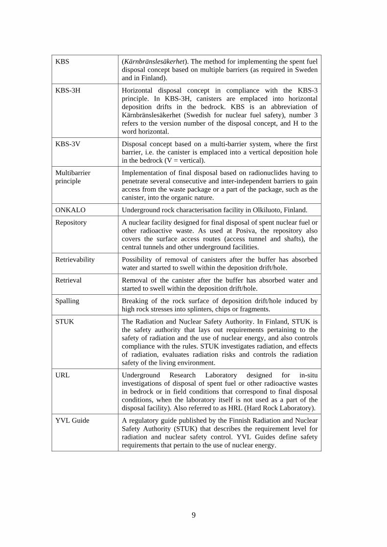
KBS (Kärnbränslesäkerhet). The method for implementing the spent fuel disposal concept based on multiple barriers (as required in Sweden and in Finland).
KBS-3H Horizontal disposal concept in compliance with the KBS-3 principle. In KBS-3H, canisters are emplaced into horizontal deposition drifts in the bedrock. KBS is an abbreviation of Kärnbränslesäkerhet (Swedish for nuclear fuel safety), number 3 refers to the version number of the disposal concept, and H to the word horizontal.
KBS-3V Disposal concept based on a multi-barrier system, where the first barrier, i.e. the canister is emplaced into a vertical deposition hole in the bedrock (V = vertical).
Multibarrier principle
Implementation of final disposal based on radionuclides having to penetrate several consecutive and inter-independent barriers to gain access from the waste package or a part of the package, such as the canister, into the organic nature.
ONKALO Underground rock characterisation facility in Olkiluoto, Finland.
Repository A nuclear facility designed for final disposal of spent nuclear fuel or other radioactive waste. As used at Posiva, the repository also covers the surface access routes (access tunnel and shafts), the central tunnels and other underground facilities.
Retrievability Possibility of removal of canisters after the buffer has absorbed water and started to swell within the deposition drift/hole.
Retrieval Removal of the canister after the buffer has absorbed water and started to swell within the deposition drift/hole.
Spalling Breaking of the rock surface of deposition drift/hole induced by high rock stresses into splinters, chips or fragments.
STUK The Radiation and Nuclear Safety Authority. In Finland, STUK is the safety authority that lays out requirements pertaining to the safety of radiation and the use of nuclear energy, and also controls compliance with the rules. STUK investigates radiation, and effects of radiation, evaluates radiation risks and controls the radiation safety of the living environment.
URL Underground Research Laboratory designed for in-situ investigations of disposal of spent fuel or other radioactive wastes in bedrock or in field conditions that correspond to final disposal conditions, when the laboratory itself is not used as a part of the disposal facility). Also referred to as HRL (Hard Rock Laboratory).
YVL Guide A regulatory guide published by the Finnish Radiation and Nuclear Safety Authority (STUK) that describes the requirement level for radiation and nuclear safety control. YVL Guides define safety requirements that pertain to the use of nuclear energy.
1. Introduction
10
1. Introduction
1.1 The objective and scope of the survey
The knowledge of bentonite and other backfill materials for nuclear waste disposal purposes in Finland has so far been fragmented. The research has mainly been based on the collaborative projects between Posiva Oy and SKB. The Finnish experts have also participated to some international projects. Most of the research projects have been single projects without the aim of creating comprehensive knowledge. This kind of the comprehensive knowledge will be needed in the preparation of the application of the construction license for the disposal facility by the end of the year 2012 and in the evaluation of the application. The BENTO programme, which started in 2007, is aimed to answer to this need for comprehensive knowledge development. The BENTO programme includes also training for new experts on bentonite. Therefore the Bentomap- survey was produced to meet these needs. The Bentomap survey included creation of the state-of-the-art report and a database of the bentonite literature. The state-of-the-art report and its database can be used for the training of authorities and experts. Another important task of the survey was to show the deficiency and reliability of the bentonite knowledge. Altogether the survey can be used for the orientation of the bentonite research in the future.
The objectives of the two year survey were
• to map the done research for buffer and backfilling materials
• to evaluate the applicability of the test results in Finnish repository solutions
• to create a database of the bentonite research including an evaluation of the research results
• to produce a separate state-of-the-art report of the done research results including evaluation, scope, limitations and possible deficiencies of the knowledge
• to create a wider perspective of the level of the national and international know-how on bentonite and backfilling research.

1. Introduction
11
The scope of the survey was to cover the THM knowledge of bentonite materials, but some research on other backfilling materials were also included. These materials are planned to be used as a buffer in the deposition hole or/and as a backfill in tunnels. Since the early outlines of the disposal concept, bentonite has been used as the reference material for buffer, while backfill material may be a mixture of bentonite and some supporting filling (ballast). The database has been created so that its core is the buffer and backfill research done by SKB and Posiva Oy. A large key words search was also done to VTT’s electronic library databases, like Compendex, Insepc, NTIS, Elsevier’s Scopus and Science Direct. Besides these also Scirus and Google Scholar databases were used. Other material included EU-projects including Febex project and Mare Curie programme, journal articles and conference papers. In the beginning the database search was limited to the latest ten years (from 1997-2008). After the evaluation of the first year it was suggested that the survey should cover also some older research, which was done accordingly. The created, new database includes thermal (T), hydraulic (H), mechanical (M), chemical (C), gaseous (G) and occasionally biological (B) property studies.
The survey has ranged from small scale laboratory test to the full-scale tests in real deep depository conditions together with their modelling. The tests include characterization of the material and description of methods and their applicability (or limitations). The modelling analysis describes the input data and boundary conditions together with reliability of the results. The database has been updated continuously during this two year period. The database was created with Access program and it is available from VTT.
The database includes over 200 different publications. The state-of-the-art report was created based on the evaluation of these publications. The report concentrated to the experimental thermo-hydro-mechanical properties of the buffer and backfill materials. The state-of-the-art report is public and available in VTT’s web-page (www.vtt.fi).
1.2 The disposal concepts
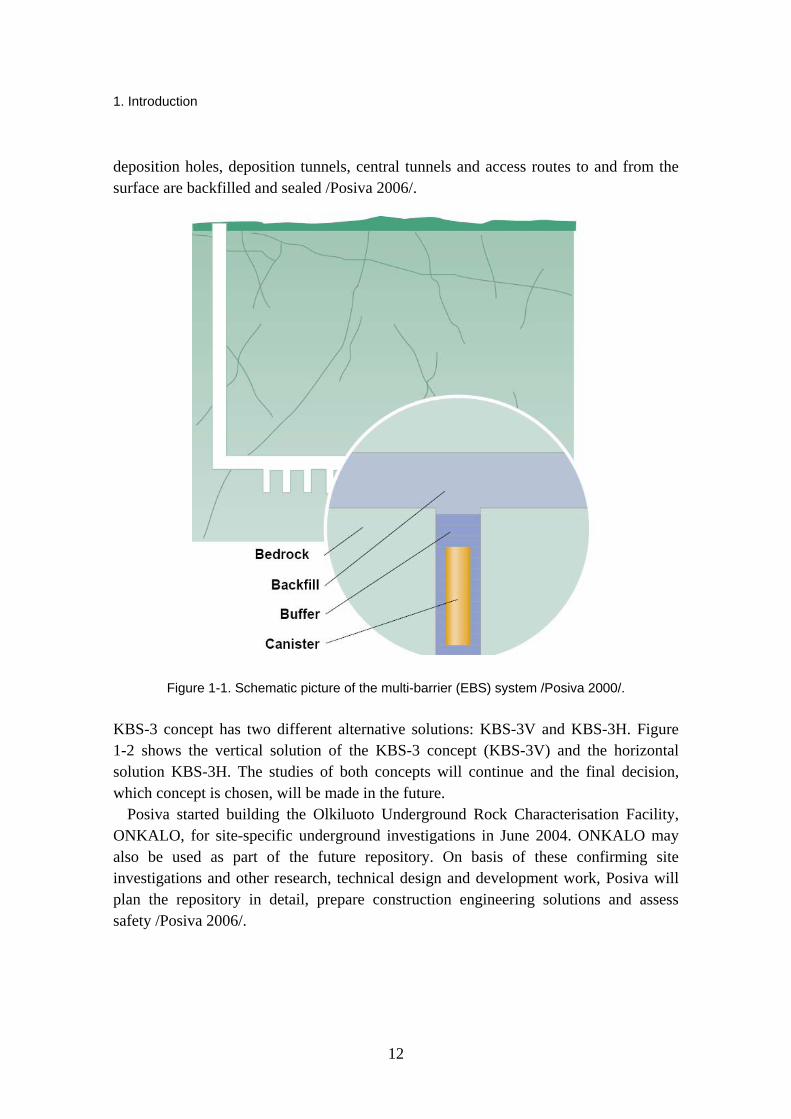
In Finland the plans for the disposal of spent nuclear fuel are based on the KBS-3 waste disposal concept in crystalline bedrock /Posiva 2006/. The KBS-3 concept was originally developed by the Swedish waste management organisation (SKB). Posiva embraced this concept more than 20 years ago. Since then Posiva and SKB have cooperated to develop and investigate the concept. This concept aims at long-term isolation and containment of spent fuel assemblies in copper canisters with a nodular cast iron insert. The concept is called as Engineering Barrier System (EBS). The parts of the EBS are illustrated in Figure 1-1. The canister is emplaced about 420 metres deep into the bedrock. Each canister is isolated from the bedrock by a thick bentonite clay layer (the buffer). After emplacing individual canisters and bentonite buffer into
1. Introduction
12
deposition holes, deposition tunnels, central tunnels and access routes to and from the surface are backfilled and sealed /Posiva 2006/.
Figure 1-1. Schematic picture of the multi-barrier (EBS) system /Posiva 2000/.
KBS-3 concept has two different alternative solutions: KBS-3V and KBS-3H. Figure 1-2 shows the vertical solution of the KBS-3 concept (KBS-3V) and the horizontal solution KBS-3H. The studies of both concepts will continue and the final decision, which concept is chosen, will be made in the future.
Posiva started building the Olkiluoto Underground Rock Characterisation Facility, ONKALO, for site-specific underground investigations in June 2004. ONKALO may also be used as part of the future repository. On basis of these confirming site investigations and other research, technical design and development work, Posiva will plan the repository in detail, prepare construction engineering solutions and assess safety /Posiva 2006/.

1. Introduction
13
Figure 1-2. KBS-3V and KBS-3H concepts /Posiva 2006/.
1.3 The purpose of buffer and backfill and their general requirements
The buffer is designed to surround and isolate copper canisters from the geosphere. The buffer material being considered is bentonite, which contains swelling clays (mainly montmorillonite) and which will be emplaced in a partially saturated state as bentonite blocks and rings. The blocks will be placed below and above the canister with the bentonite rings Figure 1-1 surrounding it /Posiva 2006/.
As regards long-term safety, the purpose of the buffer is /Posiva 2006/
• to maintain the integrity of the canisters for at least 100 000 years by protecting them from detrimental THMBC processes
• to limit and retard the release of any radionuclides from the canisters, should any be damaged.
As well as protecting canisters from external detrimental THMBC processes, the buffer should not give rise to any processes that could adversely affect either the canisters or the host rock.
In general, the purpose of the backfill is to prevent the formation of water-conductive flow paths, contribute to keeping the tunnels mechanically stable and prevent inadvertent human intrusion to the repository /Posiva 2006/.
1. Introduction
14
Based on preliminary studies, the backfill concept based on the use of precompacted blocks and pellets either from clay alone or mixtures of clay and crushed rock seems to be the most promising. The block concept has been selected as Posiva’s main backfilling alternative in the Preliminary design stage 2 of the repository /Posiva 2006/.
1.4 The general THM requirements of buffer and backfill materials
General safety requirements for the buffer and backfill are defined in safety case /for example SKB 2006/. Quantitative parameters describing isolation properties of the buffer and backfill include hydraulic conductivity, density, swelling pressure, compressibility and thermal conductivity. Currently, the work is focussed on detailed research, development and design of the disposal system /Posiva 2006/. Required physical properties of buffer include plasticity to cushion the canister from small bedrock movements, stiffness to support the canister and high density and compressibility. Small pore size and low permeability protect against radionuclide transport and adverse microbial processes. Thermal conductivity of the buffer must be sufficient to allow heat transport from the canister surface to the bedrock /Posiva 2006/.
The general material requirements for buffer according to Posiva /2006/ are
• low hydraulic conductivity (K ≤ 10-12 m/s)
• adequate density (ρs = density at complete water saturation) o prevention of colloid transport ρs > 1 650 kg/m3 o exclusion of microbial activity ρs > 1 800 kg/m3 o ensure protection of canister against rock shear ρs < 2100 kg/m3
• sufficient swelling pressure (P): o to ensure tightness and self sealing / P > 1 MPa i.e. to fill completely the space
between canister and rock o the upper limit for swelling pressure is 10 MPa, in order to avoid damage to the
canister and the rock
• sufficient thermal conductivity o to allow heat transport from canister surface to geosphere o buffer maximum temperature should remain under 100 °C and over 0 °C to
ensure long-term stability
• chemical buffering capacity • favourable pH and redox conditions of pore water to avoid canister damage.
Due the increased knowledge about the site and the expected evolution of conditions in Olkiluoto the design requirements for the backfill have been updated /Gunnarsson et al.
1. Introduction
15
2006/. Main system requirements for the backfill originate from long-term safety considerations. Additional subsystem requirements originate from operational safety and radiation protection, environmental impact, as well as from programmatic, operational and economical consideration /Gunnarsson et al. 2006/.
The general material requirements for backfill according to Gunnarsson et al. /2006/ are:
• The hydraulic conductivity should be <10-10 m/s.
• The swelling pressure of the backfill should be at least 0.1 MPa (long-term safety requirement).
• The swelling pressure of the backfill should not be smaller than 200 kPa (design requirement for current design).
• The compression modulus should be at least 10 Mpa.
• Chemical interaction between the backfill and the other EBS components need to be taken into account when assessing different alternative backfill materials.
• Suitable density, ρs, at complete water saturation is required (will be defined later on).
1.5 References for Chapter 1
Gunnarsson, D., Morén, L., Sellin, P., Keto, P. 2006. Deep repository – engineered barrier systems. Assesment of backfill materials and methods for deposition tunnels, R-06-71, SKB, Stockholm, Sweden, 52 p.
Posiva, 2000, Disposal of spent fuel in Olkiluoto Bedrock – Programme for research, development and technical design for the pre-construction phase, Report 2000-14, Posiva Oy, Olkiluoto, Finland.
Posiva, 2006, Nuclear waste management of the Olkiluoto and Loviisa power plants, Programme for Research, Development and Technical Design for 2007–2009, TKS-2006, Posiva Oy, Olkiluoto, Finland, 285 p.

2. Bentonites and backfill materials
16
2. Bentonites and backfill materials
2.1 General
Bentonite is an expansive clay material consisting mainly of montmorillonite and/or other smectites. It is chemically and mechanically stable and lends itself to plastic deformations. It also opposes the circulation of water and is permeable to gases /Pastina & Hellä 2006/. Another important attribute of bentonite is that it swells when it comes into contact with water. If compacted before or during emplacement and then expanded, the material becomes very dense, fills the voids and exhibits very low hydraulic conductivity and high swelling pressure /Ahonen et al. 2008/.
Because of the low hydraulic conductivity, diffusion is the only relevant transport process of radionuclides in bentonite. Bentonite functions as a very effective sorbent, which in turn further retards transport. The main material-specific physical variables affecting these processes are the effective porosity and surface area, as well as the cation exchange capacity of bentonite /Ochs and Talerico 2004/.
Pre-compacted bentonite blocks have been chosen to compose the buffer around the waste canister /TKS 2006/. Due to its expansion when wetted, extremely low hydraulic conductivity, high retardation capacity and plastic behavior, bentonite and other swelling clays have been planned to be used for backfilling and sealing of disposal tunnels and other underground facilities in the repository for high level spent nuclear fuel.
Several different types of bentonite, for example MX-80 and FEBEX bentonite, could be considered as buffer materials. However, aside from bentonite there are also other natural clay materials that expand when wetted, such as smectitic mixed-layer clays. Various alternative backfill materials have been studied by e.g. Johannesson & Nilsson /2006/ and Gunnarsson et al. /2006/.
Gunnarsson et al. /2006/ divided the materials investigated in the second phase of the SKB-Posiva backfilling project (BACLO) into three main categories:
1. Bentonite clays: two high-grade Na-bentonites from Wyoming (MX-80 and SPV200), one low-grade bentonite from Kutch (India Asha 230), and one high-

2. Bentonites and backfill materials
17
and one low-grade Ca-bentonite from Milos (Deponite CA-N and Milos backfill). The high-grade bentonites are used in different bentonite-ballast mixtures.
2. Smectite-rich mixed-layer clays: one from Dnešice-Plzensko Jih (DPJ) located in the Czech Republic and one from Northern Germany (Friedland clay).
3. Mixtures of bentonite and ballast: Mixtures consisting of high-grade bentonite (30, 40 and 50 w-%) and crushed rock with different type of grain size distribution or sand.
Characteristics of some bentonites and smectite-rich mixed-layer clays have been collected from various sources by Pastina & Hellä /2006/ and presented in Table 2-1.
Table 2-1. Main mineralogical and chemical characteristics of considered backfill materials /Pastina & Hellä 2006/.
2.2 Mineralogical and chemical description of the bentonite material
Bentonite clays have certain favorable properties as mentioned previously in this chapter. These material properties are dependent on the chemical composition and mineralogy of the clays.
According to Carlson /2004/ different bentonites are not necessarily similar with respect to mineralogy and geochemistry. Typically this is due to differences in the geological history of the source occurrences. Bentonites commonly originate from the
2. Bentonites and backfill materials
18
alteration occurring in mainly rhyolitic or dacitic volcanic ash or tuff, either in situ or when transported and redeposited. When ash flows of volcanic eruptions deposit as tuff layers, smectites are formed as the tuff reacts with water in low temperature conditions in the presence of excess alkali /Ahonen et al. 2008/.
2.2.1 Mineral composition of bentonite
The main component in bentonite is smectite or smectites, which are expandable clay minerals with various chemical compositions. It is these minerals that dictate the bentonite properties which are of interest in nuclear waste confinement, such as swelling ability, plasticity and cation exchange capacity. The properties depend on the amount of smectite minerals in the bulk material, smectite species and on the exchangeable cations in the interlayer position. Another clay mineral, illite, is also common in bentonites and it appears interlayered with the smectites. The major smectite species are montmorillonite, beidellite, nontronite, hectorite and saponite /Carlson 2004/.
Commercial bentonites normally contain 70–90% smectites /Ahonen et al. 2008/, and high-quality commercial bentonites contain typically over 80% of montmorillonite, which implies that various bentonite products will have similar sealing properties /Karnland et al. 2006/. The other minerals in bentonite may vary substantially, but common accessory minerals are feldspars, quartz, cristobalite, gypsum, calcite and pyrite.
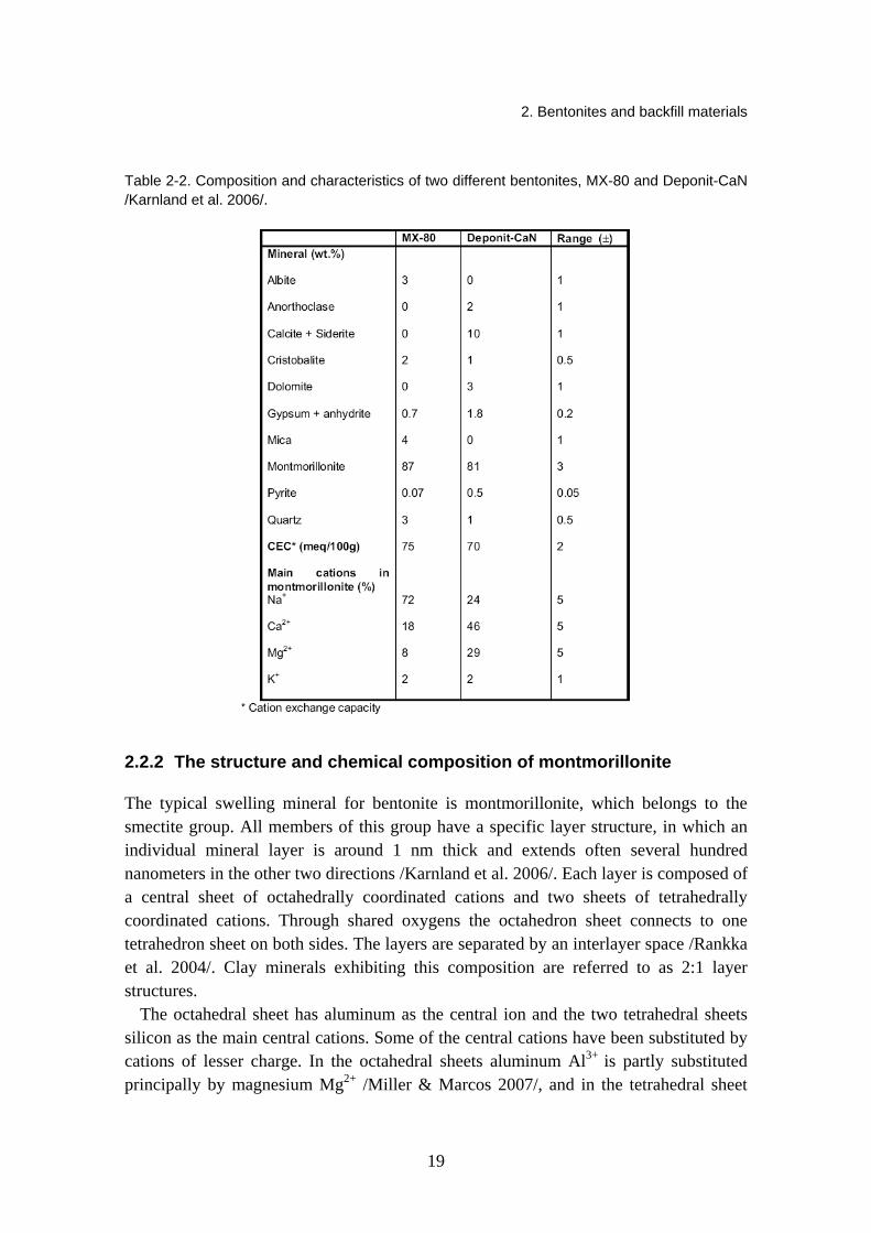
According to Karnland et al. /2006/ chemical interaction of some of the accessory minerals may enhance cementation of the buffer and decrease the longevity of the swelling mineral or the canister. They may also affect the transport properties of radionuclides in case of a canister failure. Ahonen et al. /2008/ further pinpointed that carbon, sulphur and iron are the essential components possibly affecting the chemical evolution of the disposal near-field. Iron is an important redox component in the repository near-field, and carbon may be present in different redox-states. Sulphur minerals on the other hand are considered important constituents with regards to the long-term behaviour. An example of the percentual mineral contents of two different bentonites is shown in Table 2-2.
2. Bentonites and backfill materials
19
Table 2-2. Composition and characteristics of two different bentonites, MX-80 and Deponit-CaN /Karnland et al. 2006/.
2.2.2 The structure and chemical composition of montmorillonite
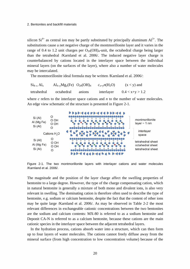
The typical swelling mineral for bentonite is montmorillonite, which belongs to the smectite group. All members of this group have a specific layer structure, in which an individual mineral layer is around 1 nm thick and extends often several hundred nanometers in the other two directions /Karnland et al. 2006/. Each layer is composed of a central sheet of octahedrally coordinated cations and two sheets of tetrahedrally coordinated cations. Through shared oxygens the octahedron sheet connects to one tetrahedron sheet on both sides. The layers are separated by an interlayer space /Rankka et al. 2004/. Clay minerals exhibiting this composition are referred to as 2:1 layer structures.
The octahedral sheet has aluminum as the central ion and the two tetrahedral sheets silicon as the main central cations. Some of the central cations have been substituted by cations of lesser charge. In the octahedral sheets aluminum Al3+
is partly substituted principally by magnesium Mg2+ /Miller & Marcos 2007/, and in the tetrahedral sheet
2. Bentonites and backfill materials
20
silicon Si4+ as central ion may be partly substituted by principally aluminum Al3+. The substitutions cause a net negative charge of the montmorillonite layer and it varies in the range of 0.4 to 1.2 unit charges per O20(OH)4-unit, the octahedral charge being larger than the tetrahedral /Karnland et al. 2006/. The induced negative layer charge is counterbalanced by cations located in the interlayer space between the individual mineral layers (on the surfaces of the layer), where also a number of water molecules may be intercalated.
The montmorillonite ideal formula may be written /Karnland et al. 2006/:
Si8–x Alx Al4–yMgy(Fe) O20(OH)4 cx+yn(H2O) (x < y) and
tetrahedral octahedral anions interlayer 0.4 < x+y > 1.2
where c refers to the interlayer space cations and n to the number of water molecules. An edge view schematic of the structure is presented in Figure 2-1.
Figure 2-1. The two montmorillonite layers with interlayer cations and water molecules /Karnland et al. 2006/.
The magnitude and the position of the layer charge affect the swelling properties of bentonite to a large degree. However, the type of the charge compensating cation, which in natural bentonite is generally a mixture of both mono and divalent ions, is also very relevant in swelling. The dominating cation is therefore often used to describe the type of bentonite, e.g. sodium or calcium bentonite, despite the fact that the content of other ions may be quite large /Karnland et al. 2006/. As may be observed in Table 2-2 the most relevant differences in exchangeable cationic concentrations between the two bentonites are the sodium and calcium contents: MX-80 is referred to as a sodium bentonite and Deponit CA-N is referred to as a calcium bentonite, because these cations are the main cationic species in the interlayer space between the adjacent tetrahedral layers.
In the hydration process, cations absorb water into a structure, which can then form up to four layers of water molecules. The cations cannot freely diffuse away from the mineral surface (from high concentration to low concentration volume) because of the

2. Bentonites and backfill materials
21
demand for electrical neutrality. Water will consequently be transported into the interlayer space and increase the interlayer distance. This causes the bentonite to swell. Water in bentonite can also exist in the pore air as a water vapour, either in the aggregates or in the larger voids between the aggregates. A more detailed description of the chemistry and mineralogy behind swelling in bentonite can be found in literature, e.g. Karnland et al. /2006/. The structure of unhydrated and hydrated montmorillonite is illustrated in Figure 2-2.
Figure 2-2. The structure of unsaturated montmorillonite (left) and saturated montmorillonite (right) /Karnland et al. 2006/.
2.2.3 Bentonite microstructure
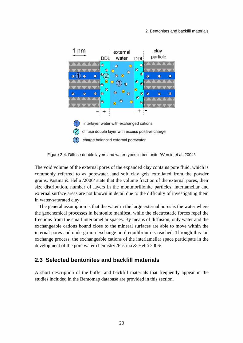
As explained before, the compacted clay (such as montmorillonite bentonite) absorbs water into the interlamellar spaces. According to /Pastina & Hellä 2006/, the volume of the larger pores is reduced by this process and depending on the density of the bentonite and on the type of adsorbed cations, the interlamellar space ranges from about 0.6 to 0.9 nm. To maintain electrical neutrality the exchangeable cations are bound at the montmorillonite surfaces, which causes a diffuse double layer to form on the surfaces of the large external pores. The formation of the layer is such that the concentration of the exchangeable cations is highest close to the surfaces and decreases with increasing distance from the surface. The generalized microstructure of MX-80 bentonite can be observed in Figure 2-3, and Figure 2-4 offers a closer look at the diffuse double layers and the bentonite water types.

2. Bentonites and backfill materials
22
Figure 2-3. The generalized microstructure of MX-80 depicting the smectite and accessory minerals, as well as the cations on the mineral surfaces /Wersin 2002/.
2. Bentonites and backfill materials
23
Figure 2-4. Diffuse double layers and water types in bentonite /Wersin et al. 2004/.
The void volume of the external pores of the expanded clay contains pore fluid, which is commonly referred to as porewater, and soft clay gels exfoliated from the powder grains. Pastina & Hellä /2006/ state that the volume fraction of the external pores, their size distribution, number of layers in the montmorillonite particles, interlamellar and external surface areas are not known in detail due to the difficulty of investigating them in water-saturated clay.
The general assumption is that the water in the large external pores is the water where the geochemical processes in bentonite manifest, while the electrostatic forces repel the free ions from the small interlamellar spaces. By means of diffusion, only water and the exchangeable cations bound close to the mineral surfaces are able to move within the internal pores and undergo ion-exchange until equilibrium is reached. Through this ion exchange process, the exchangeable cations of the interlamellar space participate in the development of the pore water chemistry /Pastina & Hellä 2006/.
2.3 Selected bentonites and backfill materials
A short description of the buffer and backfill materials that frequently appear in the studies included in the Bentomap database are provided in this section.
2. Bentonites and backfill materials
24
2.3.1 MX-80 bentonite
MX-80 bentonite is extracted from Wyoming, USA. It is a worldwide known material supplied in the form of powder homoionised to sodium. SPV200 is a product name for the same type of Wyoming Na-bentonite, and the only essential difference between the MX-80 and the SPV200 is the granule size distribution /Gunnarsson et al. 2006/. The Wyoming bentonites were formed in hydrothermal alteration of volcanic ash during the Cretaceous period.
The MX-80 bentonite consists mainly of montmorillonite (65–82% reported by Villar and Gómez-Espina /2008/, 80–85% reported by Carlson /2004/). It also contains quartz (4–12%), feldspars (5–8%), and smaller quantities of cristobalite, calcite and pyrite, and possibly traces of gypsum, illite and amphibole /Carlson 2004/.
The CEC values reported are 74 meq/100 g /Villar & Gómez-Espina 2008/, or between 80–110 meq/100 g depending on the test method /Carlson 2004/. The major exchangeable cations are Na (61 meq/100 g), Ca (10 meq/100 g) and Mg (3 meq/100 g). The liquid limit of the bentonite determined by CIEMAT laboratories is 526%, the plastic limit is 46%, the total specific surface area is about 512 m2/g and the specific gravity is 2.82 /Villar & Gómez-Espina 2008/. The hygroscopic water content at laboratory conditions is 8–11% /Villar & Gómez-Espina 2008/.
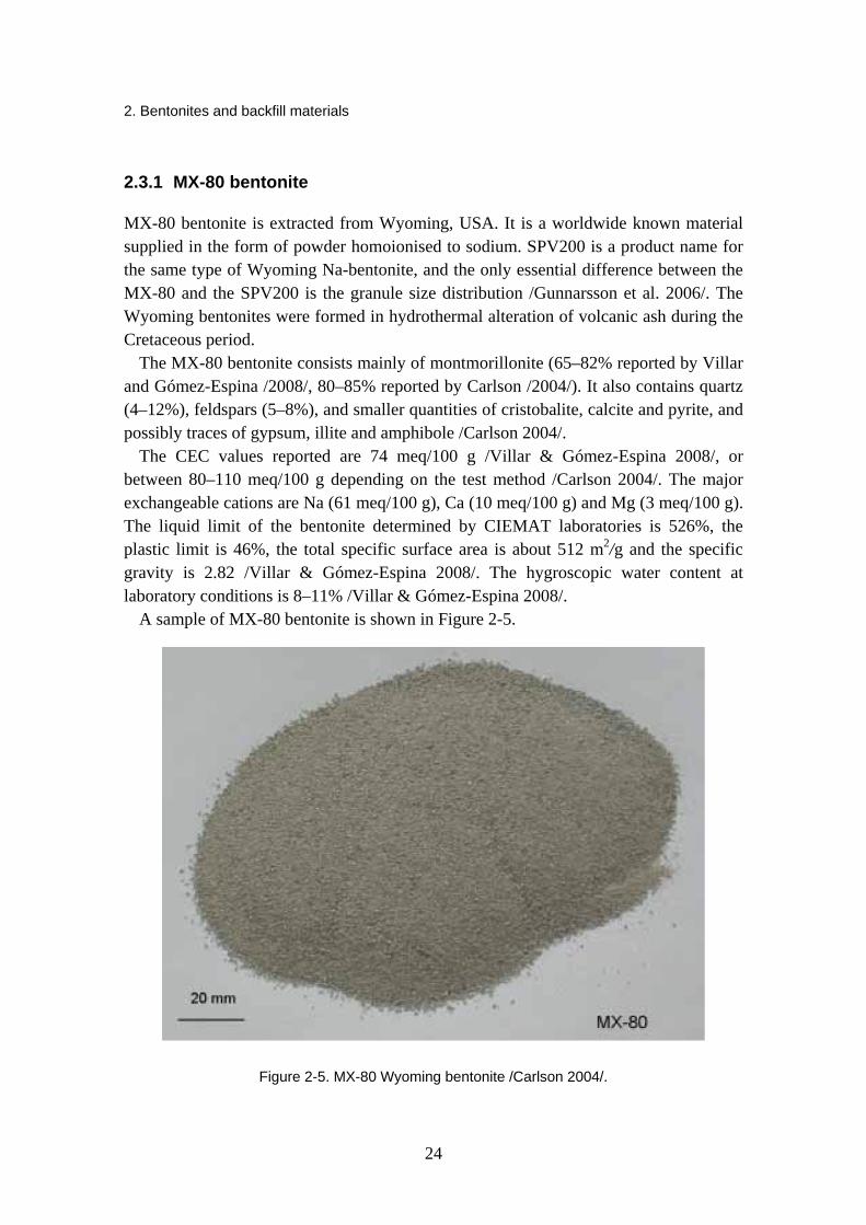
A sample of MX-80 bentonite is shown in Figure 2-5.
Figure 2-5. MX-80 Wyoming bentonite /Carlson 2004/.
2. Bentonites and backfill materials
25
2.3.2 FEBEX bentonite
FEBEX bentonite comes from the Cortijo de Archidona deposit (Almería, Spain), and was formed by the hydrothermal alteration of acid volcanic rocks.
The smectite content of the bentonite is higher than 90 percent (92 ± 3%) and it contains variable quantities of quartz (2 ± 1%), plagioclase (2 ± 1%), K-felspar, calcite and opal-CT (cristobalite-trydimite, 2 ± 1%). The smectitic phases of the FEBEX bentonite are made up of a montmorillonite-illite mixed layer, with 10–15% of illite layers.
The cation exchange capacity, CEC, ranges from 96 to 102 meq/100 g, and the major exchangeable cations are Ca (35–42 meq/100 g), Mg (31–32 meq/100 g), Na (24–27 meq/100 g) and K (2–3 meq/100 g).
The liquid limit of the bentonite is 102 ± 4%, the plastic limit is 53 ± 3%, the total specific surface area is 725 ± 47 m2/g and the specific gravity 2.70 ± 0.04. 67 ± 3% of the particles are smaller than 2 lm. The hygroscopic water content in equilibrium with the laboratory atmosphere is 13.7 ± 1.3%. /Villar & Gómez-Espina 2008, Villar & Lloret 2007/.
2.3.3 Milos bentonites
The Milos clay deposits on the isle of Milos, Greece were formed as a consequence of hydrothermal alteration of volcanic rocks during the Tertiary period.
The montmorillonite content of high-grade Milos Ca-bentonites is 75–80% /Carlson 2004/. The other minerals present are calcite (5–15%), quartz (< 5%), plagioclase and pyrite. According to Carlson /2004/ the dominant exchangeable cation in the non-activated version of this clay is Ca2+, but also other cations (Na+, Mg2+ and K+) are present in smaller proportions. The CEC determined with BaCl2 method by /Carlson 2004/ was 74.5%. The IBECO Deponit CA-N is non-activated high-grade Ca-bentonite. /Gunnarsson et al. 2006/
The low-grade bentonite clay from Milos is assumed to contain a little lower amount of smectite-group minerals than the high-grade bentonites quarried from the same deposits. It is available in large quantities and should be relatively inexpensive compared to high-grade bentonites /Gunnarsson et al. 2006/. Based on preliminary data /Johannesson & Nilsson 2006/, the amount of swelling minerals in the Miloan clay (Milos backfill) is 50–60%. The Milos backfill is non-activated Ca-bentonite.
The liquid limits determined for both Milos clays with the fall-cone method are 150–157% /Johannesson & Nilsson 2006/. This result implies that the mineralogical differences between the low- and high-grade Miloan bentonites may be relatively small /Gunnarsson et al. 2006/. The corresponding normalized free swelling values for the samples were 5.3 ml for IBECO Deponit CA-N and 5 ml for Milos backfill. A sample of high-grade Milos bentonite is shown in Figure 2-6.

2. Bentonites and backfill materials
26
Figure 2-6. Milos non-activated high-grade bentonite Deponit CA-N /Karnland et al. 2006/.
2.3.4 Asha bentonite
Extensive deposits of Indian Na-bentonite Asha exist at the Kutch district on the northwest-coast of India. The bentonite is associated with the basaltic Deccan Trap rocks of Tertiary age and was formed through hydrothermal alteration of volcanic ash in saline water. The bentonite occurs in scattered and disconnected pockets or as interlayers within the basaltic rocks. /Karnland et al. 2006/.
Asha 230 is a low-grade natural Na-bentonite, and based on preliminary data /Johannesson & Nilsson 2006/, the amount of swelling minerals in this bentonite clay is 60–65%. The liquid limits determined for Asha 230 with the fall-cone method are 180% /Johannesson & Nilsson 2006/. The corresponding normalized free swelling value for the sample was 8.4 ml. A sample of Asha bentonite is shown in Figure 2-7.

2. Bentonites and backfill materials
27
Figure 2-7. Asha bentonite /Karnland et al. 2006/.
2.3.5 Friedland clay
Friedland clay is a smectite-rich clay from north-eastern Germany, near the town of Neubrandenburg. The clay is of Tertiary origin and was formed by a complex process including sedimentation, weathering, erosion and hydrothermal alteration.
The swelling component of the clay consists of mixed-layer mica/montmorillonite and the content is estimated to be on average 45% /Pusch 1998/. However, also significantly lower values (max 35%) have been reported by Carlson /2004/ and Karnland et al. /2006/. Other minerals present include quartz (24%), mica (13%), chlorite (11%), feldspar (5%) and carbonate (2%), also kaolinite /Pusch 1998, Carlson 2004/. Carlson /2004/ describes the mineralogy of the clay as a “mixture of several clay minerals and detrital quartz, feldspars, siderite and small amount of pyrite”.
The dominant exchangeable cation is Na+ and the CEC of the clay varies from 35–45 meq /100 g /Carlson 2004/. The liquid limit of Friedland clay is 109% /Johannesson & Nilsson 2006/ and the normalized free swelling amounted to 7.7 ml /Gunnarsson et al. 2006/. A sample of Friedland clay is shown in Figure 2-8.

2. Bentonites and backfill materials
28
Figure 2-8. Friedland clay /Carlson 2004/.
2.3.6 DPJ clay
DPJ clay originates from a place called Dnešice (Dnešice-Plzensko Jih) located in the Czech Republic. It’s a smectite-rich mixed layer clay.
The evaluated smectite content of the clay varies from 20% to 66% /Carlson 2004, Prikryl et al. 2006/. The smectite mineral is either montmorillonite or beidellite, and layers of illite are present between the smectite layers /Prikryl et al. 2006/. The other minerals present in the bulk samples are kaolinite (0–50%), illite, quartz and goethite /Carlson 2004, Prikryl et al. 2006/.
The CEC of the clay determined with BaCl2 and NH4-acetate methods was 40–47% /Carlson 2004/. The exchangeable cations present are Ca2+ and Mg2+ /Carlson 2004/. DPJ clay has a liquid limit of 109% and a normalized free swelling of 4.8 ml /Johannesson and Nilsson 2006/. A sample of DPJ clay is shown in Figure 2-9.

2. Bentonites and backfill materials
29
Figure 2-9. Dnešice clay /Carlson 2004/.
2.4 References for Chapter 2
Ahonen, L., Korkeakoski, P., Tiljander, M., Kivikoski, H., Laaksonen, R. 2008. Quality assurance of the Bentonite Material, Working Report 2008-33, Posiva Oy, Olkiluoto, Finland, p. 126.
Carlson, L. 2004. Bentonite mineralogy, Part 1: Methods of investigation – a literature review, Part 2: Mineralogical research of selected bentonites, Working report 2004–02, Posiva Oy, Olkiluoto, Finland, p. 78.
Gunnarsson, D., Morén, L., Sellin, P., Keto, P. 2006. Deep Repository – Engineered Barrier Systems. Assessment of Backfill Materials and Methods for Deposition Tunnels, SKB R-06-71, SKB, Stockholm, Sweden.
Johannesson, L.-E., Nilsson, U. 2006. Deep repository – Engineered barrier system. Geotechnical properties of candidate backfill materials. Laboratory tests and calculations for determining performance, SKB R-06-73, SKB, Stockholm, Sweden.
Karnland, O., Olsson, S., Nilsson, U. 2006. Mineralogy and sealing properties of various bentonites and smectite-rich clay materials, SKB 2006, TR-06-30, Stockholm, Sweden, 70 p.
Miller, B., Marcos, N. 2007. Process Report – Feps and Scenarios for a Spent Nuclear Fuel Repository at Olkiluoto, Report 2007-12, Posiva Oy, Olkiluoto, Finland.
Ochs, M., Talerico, C. 2004. SR-Can. Data and uncertainty assessment. Migration parameters for the bentonite buffer in the KBS-3 concept. SKB TR-04-18, SKB, Stockholm, Sweden.

2. Bentonites and backfill materials
30
Pastina, B., Hellä, P. 2006. Expected evolution of a spent fuel repository at Olkiluoto. POSIVA 2006-05. Posiva Oy, Olkiluoto, Finland.
Pŕikryl, R., Carlson, L., Keto, P., Kolařikova, I., Hanus, R., Brabec, L., Vejsada, J., Pacovský, J., Kundrnáčová, I., Karnland, O. 2006. Verification of substitution of bentonites by montmorillonitic clays. Summary on Czech montmorillonitic clays, Working Report 2006–62, Posiva Oy, Olkiluoto, Finland.
Pusch, R. 1998. Backfilling with mixtures of bentonite/ballast materials or natural smectitic clay, SKB TR-98-16, SKB, Stockholm, Sweden.
Rankka, K., Andersson-Sköld, Y., Hultén, C., Larsson, R., Leroux, V., Dahlin, T. 2004. Quick Clay in Sweden, Report 65, Swedish Geotechnical Institute, Sweden.
Villar, M.V., Gómez-Espina, R. 2008. Effect of temperature on the water retention capacity of FEBEX and MX-80 bentonites, Unsaturated Soils, Advances in Geo-Engineering, London, UK.
Villar, M.V., Lloret, A. 2007. Dismantling of the first section of the FEBEX in situ test: THM laboratory tests on the bentonite blocks retrieved, Elsevier 2007, Physics and Chemistry of the Earth Vol. 32, Amsterdam, The Netherlands, pp. 716–729.
Wersin, P. 2002. Geochemical modelling of bentonite porewater in high-level waste repositories. Journal of Contaminant Hydrology 61, pp. 405–422.
Wersin, P., Curti, E., Appelo, C.A.J. 2004. Modelling bentonite–water interactions at high solid/liquid ratios: swelling and diffuse double layer effects, Applied Clay Science, Elsevier, Amsterdam, The Netherlands, pp. 249–257.
3. Thermal properties
31
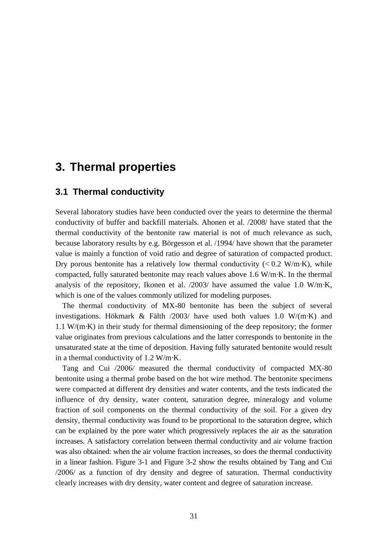
3. Thermal properties
3.1 Thermal conductivity
Several laboratory studies have been conducted over the years to determine the thermal conductivity of buffer and backfill materials. Ahonen et al. /2008/ have stated that the thermal conductivity of the bentonite raw material is not of much relevance as such, because laboratory results by e.g. Börgesson et al. /1994/ have shown that the parameter value is mainly a function of void ratio and degree of saturation of compacted product. Dry porous bentonite has a relatively low thermal conductivity (< 0.2 W/m·K), while compacted, fully saturated bentonite may reach values above 1.6 W/m·K. In the thermal analysis of the repository, Ikonen et al. /2003/ have assumed the value 1.0 W/m·K, which is one of the values commonly utilized for modeling purposes.
The thermal conductivity of MX-80 bentonite has been the subject of several investigations. Hökmark & Fälth /2003/ have used both values 1.0 W/(m·K) and 1.1 W/(m·K) in their study for thermal dimensioning of the deep repository; the former value originates from previous calculations and the latter corresponds to bentonite in the unsaturated state at the time of deposition. Having fully saturated bentonite would result in a thermal conductivity of 1.2 W/m·K.
Tang and Cui /2006/ measured the thermal conductivity of compacted MX-80 bentonite using a thermal probe based on the hot wire method. The bentonite specimens were compacted at different dry densities and water contents, and the tests indicated the influence of dry density, water content, saturation degree, mineralogy and volume fraction of soil components on the thermal conductivity of the soil. For a given dry density, thermal conductivity was found to be proportional to the saturation degree, which can be explained by the pore water which progressively replaces the air as the saturation increases. A satisfactory correlation between thermal conductivity and air volume fraction was also obtained: when the air volume fraction increases, so does the thermal conductivity in a linear fashion. Figure 3-1 and Figure 3-2 show the results obtained by Tang and Cui /2006/ as a function of dry density and degree of saturation. Thermal conductivity clearly increases with dry density, water content and degree of saturation increase.

3. Thermal properties
32
Figure 3-1.Thermal conductivity as a function of dry density for different water contents w /Tang and Cui 2006/.
Figure 3-2. Thermal conductivity as a function of the degree of saturation for different dry densities /Tang and Cui 2006/.
Börgesson et al. /1994/ have conducted several laboratory tests on the thermal conductivity of buffer materials.
Water saturated samples were studied in triaxial tests and in a so-called saturation apparatus to determine the influence of void ratio on thermal conductivity. The

3. Thermal properties
33
measured values fell fairly well within theoretical limits /Börgesson et al. 1994/, however the values measured on samples close to water saturation differed very little in spite of the difference in void ratio and, thus, it may be concluded that the number of tests is too small to allow any definite conclusions. The results for water saturated samples are presented in Table 3-1.
Table 3-1. Measurements on samples close to water saturation. The note satap refers to the samples that were prepared in the saturation apparatus. The other samples were taken from triaxial tests. Sr stands for degree of saturation, e for void ratio and λ for thermal conductivity. /Börgesson et al. 1994/.
To increase understanding of the effect of drying and water redistribution on the temperature in a repository, Börgesson et al. /1994/ also attempted to determine the influence of the degree of saturation on thermal conductivity. A series of tests were conducted on MX-80 bentonite with the void ratio e = 0.8 and with water ratios varying between that of air-dry bentonite, i.e. w = 10% and w = 25%, which corresponds to almost complete saturation. The results are presented in Table 3-2.
Table 3-2. Tests with varying degrees of saturation and void ratio close to e = 0.8 /Börgesson et al. 1994/. Sr stands for degree of saturation, e for void ratio, λ for the thermal conductivity, w for water ratio and ρ for density.

3. Thermal properties
34
The results for thermal conductivities are plotted as a function of the degree of saturation in Figure 3-3. Thermal conductivity of MX-80 (void ratio e ≈ 0.8) as a function of the degree of saturation /Börgesson et al. 1994/. The diagram depicts a fairly distinct line in spite of the difference in void ratio, except for the sample with Sr = 70%, and shows that the influence of the degree of saturation is larger in the interval 40% < Sr < 60% than when Sr > 80%.
Figure 3-3. Thermal conductivity of MX-80 (void ratio e ≈ 0.8) as a function of the degree of saturation /Börgesson et al. 1994/.
In order to evaluate how thermal conductivity values from laboratory tests differ from field test data, Börgesson et al. /1994/ also made measurements on dense blocks of the same type used in the Stripa Buffer Mass Test. Referring to different stages of the field test, the blocks were examined for different e and Sr. There were three block types:
1. block compacted for BMT in Stripa
2. block compacted by adding a certain amount of water to the bentonite before compaction to obtain a certain degree of saturation and then achieving the desired void ratio by compacting the block to a defined height
3. block made and saturated in the saturation apparatus.
The bentonite type was MX-80 and the results are shown in Table 3-3.

3. Thermal properties
35
Table 3-3. Thermal conductivity of MX-80 bentonite blocks /Börgesson et al. 1994/. Two measurements were made for the first two block types and an average thermal conductivity was also calculated.
Rutqvist and Tsang /2008/ have fitted a function to experimental data given by Börgesson and Hernelind /1999/ and obtained thermal conductivity λ for MX-80 bentonite in the form of the following relations (here Sr is the degree of saturation):
0.30.3 ( 0.25) 1.81.3
rSλλλ
== + − ×=
for Sr < 0.25
for 0.25 < Sr < 0.8 for Sr > 0.8
(3-1)
They have also adopted the above equations and values for the backfill material which contains 30% MX-80 bentonite and 70% crushed rock, whereas Börgesson and Hernelind /1999/ have used the value 1.5 W/m·K in their experiments for 30/70 backfill.
Hökmark et al. /2007/ have regarded heat and moisture transport in the barrier of the temperature buffer test (TBT) large-scale experiment. TBT includes two vertical 1 500 W heaters, stacked on top of each other in a KBS-3 type disposal hole with 0.5 m of compacted MX-80 bentonite in between. The experiment is run at high temperatures and with controlled hydraulic boundary conditions at the Äspö Hard Rock Laboratory in Sweden 420 m below ground. The test begun in March 2003, and its main purpose is to examine the response of the barrier materials to high temperatures and to high temperature gradients. Thermal conductivity values were calculated using the slopes of the temperature curves obtained from measurements.
In Figure 3-4, data from lab-scale experiments has been presented and the figure shows that the sensitivity to saturation variations in MX-80 bentonite is not large in the saturation range above 70%, but that a 10% drying below 60% should give a clear effect. Figure 3-5 on the other hand shows thermal conductivity as a function of time in various positions at different distances from the lower heater.

3. Thermal properties
36
Figure 3-4. Thermal conductivity as function of the degree of saturation for MX-80 bentonite. The legend provides the void ratio. /Hökmark et al. 2007/.
Figure 3-5. Thermal conductivity as function of time at different positions. The legend gives the radial distance from the heater axis in meters. The curves corresponding to the three positions closest to the heater are specifically labeled. /Hökmark et al. 2007/.
The latter figure indicates that there was an early and fast decrease in thermal conductivity at different distances from the heater, and assumes an initial bentonite
3. Thermal properties
37
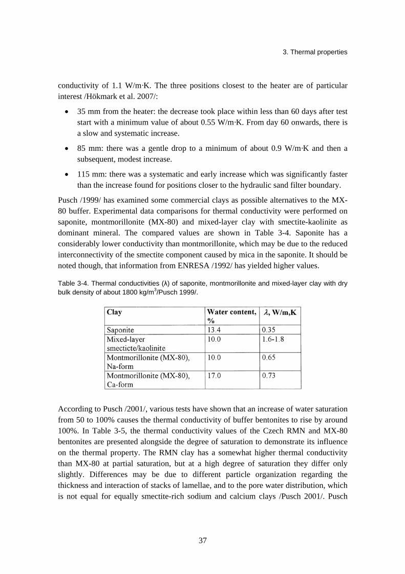
conductivity of 1.1 W/m·K. The three positions closest to the heater are of particular interest /Hökmark et al. 2007/:
• 35 mm from the heater: the decrease took place within less than 60 days after test start with a minimum value of about 0.55 W/m·K. From day 60 onwards, there is a slow and systematic increase.
• 85 mm: there was a gentle drop to a minimum of about 0.9 W/m·K and then a subsequent, modest increase.
• 115 mm: there was a systematic and early increase which was significantly faster than the increase found for positions closer to the hydraulic sand filter boundary.
Pusch /1999/ has examined some commercial clays as possible alternatives to the MX-80 buffer. Experimental data comparisons for thermal conductivity were performed on saponite, montmorillonite (MX-80) and mixed-layer clay with smectite-kaolinite as dominant mineral. The compared values are shown in Table 3-4. Saponite has a considerably lower conductivity than montmorillonite, which may be due to the reduced interconnectivity of the smectite component caused by mica in the saponite. It should be noted though, that information from ENRESA /1992/ has yielded higher values.
Table 3-4. Thermal conductivities (λ) of saponite, montmorillonite and mixed-layer clay with dry bulk density of about 1800 kg/m3/Pusch 1999/.
According to Pusch /2001/, various tests have shown that an increase of water saturation from 50 to 100% causes the thermal conductivity of buffer bentonites to rise by around 100%. In Table 3-5, the thermal conductivity values of the Czech RMN and MX-80 bentonites are presented alongside the degree of saturation to demonstrate its influence on the thermal property. The RMN clay has a somewhat higher thermal conductivity than MX-80 at partial saturation, but at a high degree of saturation they differ only slightly. Differences may be due to different particle organization regarding the thickness and interaction of stacks of lamellae, and to the pore water distribution, which is not equal for equally smectite-rich sodium and calcium clays /Pusch 2001/. Pusch
3. Thermal properties
38
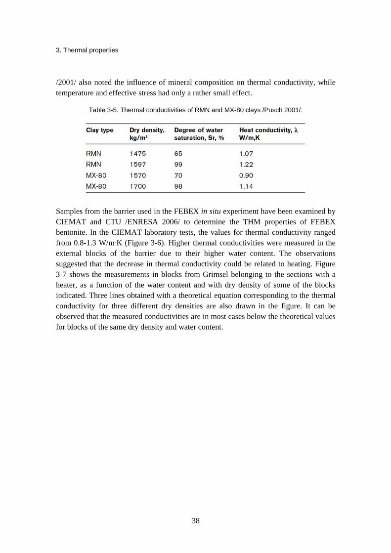
/2001/ also noted the influence of mineral composition on thermal conductivity, while temperature and effective stress had only a rather small effect.
Table 3-5. Thermal conductivities of RMN and MX-80 clays /Pusch 2001/.
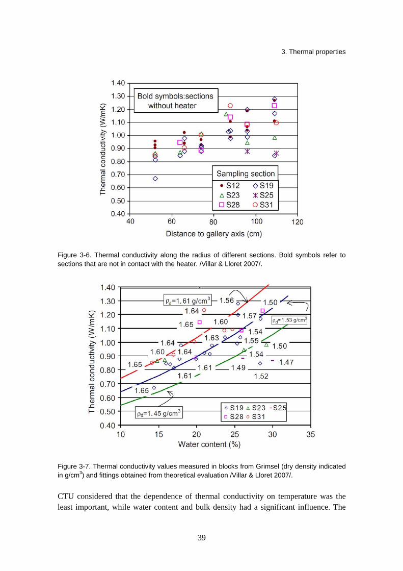
Samples from the barrier used in the FEBEX in situ experiment have been examined by CIEMAT and CTU /ENRESA 2006/ to determine the THM properties of FEBEX bentonite. In the CIEMAT laboratory tests, the values for thermal conductivity ranged from 0.8-1.3 W/m·K (Figure 3-6). Higher thermal conductivities were measured in the external blocks of the barrier due to their higher water content. The observations suggested that the decrease in thermal conductivity could be related to heating. Figure 3-7 shows the measurements in blocks from Grimsel belonging to the sections with a heater, as a function of the water content and with dry density of some of the blocks indicated. Three lines obtained with a theoretical equation corresponding to the thermal conductivity for three different dry densities are also drawn in the figure. It can be observed that the measured conductivities are in most cases below the theoretical values for blocks of the same dry density and water content.
3. Thermal properties
39
Figure 3-6. Thermal conductivity along the radius of different sections. Bold symbols refer to sections that are not in contact with the heater. /Villar & Lloret 2007/.
Figure 3-7. Thermal conductivity values measured in blocks from Grimsel (dry density indicated in g/cm3) and fittings obtained from theoretical evaluation /Villar & Lloret 2007/.
CTU considered that the dependence of thermal conductivity on temperature was the least important, while water content and bulk density had a significant influence. The

3. Thermal properties
40
increase of thermal conductivity with the increase of dry density and water content has also been noted by numerous other studies /e.g. Tang & Cui 2006, Börgesson et al. 2001/. In the CTU investigations, while water content varied from 12 to 29% and dry density from 1.54 to 1.71 g/cm3 for intact blocks with their natural water content, thermal conductivity increased with water content from 0.69 up to 1.12 W/m·K. For remoulded and partly dried samples, water content was between 8–12% and mean dry density had a value of 1.66 g/cm3 as thermal conductivity ranged from 0.62 to 0.82 W/m·K. For dried samples, the values were between 0.48–0.57 W/m·K. Differences in thermal properties had not been observed with respect to the temperature experienced by the blocks during the five years of the in situ experiment, and therefore it was proposed that heating up to 77 ºC during five years had not had an irreversible effect on the thermal properties of the FEBEX bentonite /ENRESA 2006/. Results obtained by CIEMAT and CTU were in good accordance.
Experimental results from a series of laboratory tests pertaining to the FEBEX project and performed under thermal gradient and dismantled after 0.5, 1, 2 and 8 years operation have been collected by Villar et al. /2008/ and are presented in Figure 3-8 for FEBEX bentonite. A value of 0.47 W/m·K has been adopted for the dry thermal conductivity and 1.15 W/m·K for the saturated thermal conductivity.
Figure 3-8. Thermal conductivity for FEBEX bentonite, experimental results as well as model fitting /Villar et al. 2008/.
3. Thermal properties
41
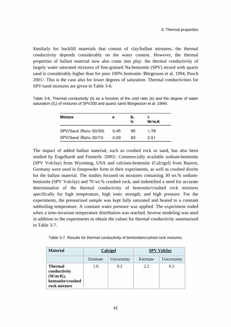
Similarly for backfill materials that consist of clay/ballast mixtures, the thermal conductivity depends considerably on the water content. However, the thermal properties of ballast material now also come into play: the thermal conductivity of largely water saturated mixtures of fine-grained Na-bentonite (SPV) mixed with quartz sand is considerably higher than for pure 100% bentonite /Börgesson et al. 1994, Pusch 2001/. This is the case also for lower degrees of saturation. Thermal conductivities for SPV/sand mixtures are given in Table 3-6.
Table 3-6. Thermal conductivity (λ) as a function of the void ratio (e) and the degree of water saturation (Sr) of mixtures of SPV200 and quartz sand /Börgesson et al. 1994/.
The impact of added ballast material, such as crushed rock or sand, has also been studied by Engelhardt and Finsterle /2003/. Commercially available sodium-bentonite (SPV Volclay) from Wyoming, USA and calcium-bentonite (Calcigel) from Bayern, Germany were used in finepowder form in their experiments, as well as crushed diorite for the ballast material. The studies focused on mixtures containing 30 wt.% sodium-bentonite (SPV Volclay) and 70 wt.% crushed rock, and indentified a need for accurate determination of the thermal conductivity of bentonite/crushed rock mixtures specifically for high temperature, high ionic strength, and high pressure. For the experiments, the pressurized sample was kept fully saturated and heated to a constant subboiling temperature. A constant water pressure was applied. The experiment ended when a time-invariant temperature distribution was reached. Inverse modeling was used in addition to the experiments to obtain the values for thermal conductivity summarized in Table 3-7.
Table 3-7. Results for thermal conductivity of bentonite/crushed rock mixtures.
Material Calcigel SPV Volclay
Estimate Uncertainty Estimate Uncertainty
Thermal conductivity (W/m·K), bentonite/crushed rock mixture
1.6 0.2 2.2 0.2
3. Thermal properties
42
The results show that the thermal conductivity of SPV Volclay/crushed rock mixtures is higher than that of Calcigel / crushed rock mixtures. Engelhardt and Finsterle /2003/ explain that the influence of the ballast material on the thermal properties of the mixture is significant, depending on whether rounded sand or longish and squared grains are used. The irregular shape of the crushed rock provides more contact points and therefore heat transfer is more efficient compared to homogeneous bentonite. The study also finds that the thermal parameters are strongly influenced by the exchangeable ion of the bentonite and the ionic strength of the pore water.
The thermal conductivity of bentonite and mixtures of bentonite and silica-sand were determined by a thermistor technique proposed by Ould-Lahoucine et al. /2002/ and by comparing the measured and simulated temperature–time histories. The obtained data as well as other existing data was then compared with various existing correlations. The bentonite used in the experiments was Kunigel V1 (Kunimine Industries), but other existing data also included MX-80 data by Börgesson et al. /1994/. The Montmorillonite content of MX-80 is about 75% while it is 50% in Kunigel V1. Thermal conductivity values were also measured and compared for the mixture of bentonite and silica-sand.
The conclusions were summarized as follows /Ould-Lahoucine et al. 2002/:
(a) In the prediction of thermal conductivity of bentonite, the equation of Sakashita and Kumada /1998/ provides the most accurate predictions. The simplified form of their correlations is given as
( ){ }0.285 0.731b,p 0 r/ 1 9.750 0.706
nn Sλ λ
+= + − (3-2)
where λb,p represents the predicted thermal conductivity, Sr degree of saturation, n porosity and λ0 is the thermal conductivity of dry bentonite obtained by:
( ) ( )30 0.0497 0.222 1 0.968 1 .n nλ = + − + − (3-3)
The comparison of the Sakashita and Kumada equation with data values is illustrated in Figure 3-9.
(b) In evaluating the thermal conductivity of bentonite and silica-sand mixtures, the mixtures can be treated as suspensions.
(c) The thermal conductivity of the bentonite and silica-sand mixture can be predicted with sufficient accuracy with the equations derived by Fricke /1924/, or Bruggeman /1935/.
(d) The scattering of the previously reported data for mixtures is larger than the data measured in this study, however, the tendency in the variation of thermal conductivity with water content and the volume ratio of silica-sand in the sample is similar.
Table 3-8 and Table 3-9 show the values measured by Ould-Lahoucine et al. /2002/ for Kunigel VI bentonite and the bentonite/sand mixture, respectively.

3. Thermal properties
43
Table 3-8. Measured and calculated thermal conductivities of bentonite /Ould-Lahoucine et al. 2002/. Here ρm is bulk density, n porosity, Sr the degree of saturation, λm,e, the measured thermal conductivity of mixtures and λb,p the thermal conductivity of bentonite calculated with the Sakashita and Kumada equation.
3. Thermal properties
44
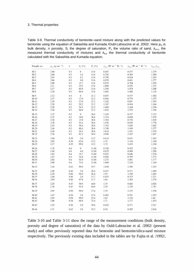
Table 3-9. Thermal conductivity of bentonite–sand mixture along with the predicted values for bentonite using the equation of Sakashita and Kumada /Ould-Lahoucine et al. 2002/. Here ρm is bulk density, n porosity, Sr the degree of saturation, Ps the volume ratio of sand, λm,e, the measured thermal conductivity of mixtures and λb,p the thermal conductivity of bentonite calculated with the Sakashita and Kumada equation.
Table 3-10 and Table 3-11 show the range of the measurement conditions (bulk density, porosity and degree of saturation) of the data by Ould-Lahoucine et al. /2002/ (present study) and other previously reported data for bentonite and bentonite/silica-sand mixture respectively. The previously existing data included in the tables are by Fujita et al. /1992/,

3. Thermal properties
45
Suzuki et al. /1992/, Suzuki and Tanigushi /1999/, Kiyohashi and Banno /1995, 1996/ and Börgesson et al. /1994/.
Table 3-10. Measurement conditions for the thermal conductivity of Kunigel V1 bentonite (for first four studies) and MX-80 bentonite (for Börgesson et al. /1994/) /Ould-Lahoucine et al. 2002/. Here ρm is bulk density, n porosity and Sr is the degree of saturation.
Table 3-11. Measurement conditions for the thermal conductivity of bentonite/sand mixture /Ould-Lahoucine et al. 2002/. Börgesson et al. used MX-80 bentonite and the other studies had Kunigel V1 bentonite as the studied bentonite material. Here ρm is bulk density, n porosity, Sr the degree of saturation and Ps the volume ratio of sand.
Figure 3-9. Thermal conductivity values predicted by the Sakashita-Kumada equations with data for bentonite /Ould-Lahoucine et al. 2002/.

3. Thermal properties
46
Börgesson et al. /2001/ performed a THM characterization on the bentonite OT-9607 (a natural sodium bentonite with the same origin as Kunigel V1, but it is much coarser) produced for the simulated deposition hole in the THM experiment at the Kamaishi mine in Japan. The thermal conductivity of the buffer material was measured with a so-called Quick Thermal Conductivity Meter (QTM). With this technique a probe of known thermal conductivity is put in contact with a sample of bentonite, and the temperature development is measured during heating. The measurements were made on samples with a dry density of 1.65 g/cm3
at different water ratios. The results are presented in Figure 3-10. The strong dependence on water ratio is evident.
Figure 3-10. Measured thermal conductivity of bentonite OT-9607 at a dry density of 1.65 g/cm3 /Börgesson et al. 2001/.
KENTEX (KAERI Engineering-scale THM Experiment for an Engineered Barrier System) is an experiment to study THM behavior in an engineered barrier system, and is designed as a third scale of the engineered barrier system adopted for the Korean reference repository concept. To support the KENTEX experiment, laboratory tests were conducted and the thermal conductivity of compacted bentonite was measured within the gravimetric water content range of 11.9% to 25.0% /Cho et al. 2009/. The bentonite blocks (dimensions 150 × 60 × 20 mm) were made of Kyungju Ca-bentonite and had a dry density of 1.5 Mg/m3. They were uniaxially compacted to the desired density, and a quick thermal conductivity meter was then used at a laboratory temperature of 25 °C. At this dry density, the relation between the thermal conductivity and water content could be fitted to a straight line which along with the measured values are presented in Figure 3-11.

3. Thermal properties
47
Figure 3-11. Thermal conductivities of Kyungju bentonite with a dry density of 1.5 Mg/m2 as a
function of water content.Here k is the thermal conductivity and w is the water content /Cho et al. 2009/.
3.2 Specific heat
Not many investigations to determine the specific heat of bentonite have been covered in literature. Börgesson and Hernelind /1999/, however, have determined an equation for specific heat c of MX-80 bentonite and calculated c as the weight average of the specific heat of water and particles:
( ) ( )800 / 1 4200 / 1 c w w w= + + + (3-4)
Eqn. (3-4) yields the values presented in Table 3-12.
Table 3-12. Heat capacity c of the buffer material as a function of the water ratio w /Börgesson & Hernelind 1999/.

3. Thermal properties
48
For the backfill mixture of 30% MX-80 bentonite and 70% crushed rock, Börgesson and Hernelind /1999/ have estimated a value of 1200 Ws/kg·K. Another value that has been used for 30% buffer quality bentonite and 70% crushed granitic rock mixture as well as Friedton backfill is 1 400 Ws/kg·K /SKB 2006/.
Engelhardt and Finsterle /2003/ have pursued useful methods for estimating the permeability, thermal conductivity, and specific heat of various bentonite / crushed rock mixtures for the conditions expected to prevail at the Äspö Hard Rock Laboratory. Laboratory experiments were conducted and inverse modeling techniques employed to estimate effective thermal parameters. All experiments were conducted with mixtures containing sodium- (SPV Volclay) or calcium-bentonite (Calcigel). The inversely estimated specific heat for Calcigel was 810 J/kg·K and for SPV Volclay 1020 J/kg·K, which is consistent with the predictions of the empirical relationships. Highest value was thus reached for the combination of the sodium bentonite SPV Volclay with crushed rock.
According to Engelhardt and Finsterle /2003/, the diffuse double layer results in a closer packing of the water molecules than in free water: Dipoles have less freedom of movement and absorb less thermal energy. The degree of orientation of the water molecules and the thickness of the water layer are controlled by the type of cation. Due to the higher valence of the calcium, more water molecules are bounded in the Stern layer and absorb less thermal energy than in pure water. This implies that adding water of higher ionic strength would lower the specific heat of bentonite/crushed rock mixtures as compared to adding pure water.
The influence of temperature on the specific heat seems to be insignificant /Cho et al. 2002/. As can be seen in Figure 3-12, the specific heat is not very dependent on dry density either.
Figure 3-12. The specific heat of two bentonites, the Japanese Na-bentonite Kunigel-V1 (data by Kumata et al. /1987/) and MX-80 (data by Börgesson et al. /1994/) /Cho et al. 2002/.

3. Thermal properties
49
For the simulation of the KENTEX experiment, Cho et al. /2009/ have defined the specific heat of Kyungju bentonite as 980 J/kg ºC.
3.3 Thermal expansion coefficient
The coefficients of thermal expansion for the compacted bentonite have been reported by Börgesson et al. /1988/, and are presented in Table 3-13. They were measured at the temperature range of 20 to 60 ºC. As shown in the table, the thermal expansion coefficient decreases with increasing dry density in this temperature range, but no significant difference is observed. Therefore the coefficient of thermal expansion can be assumed to be constant for the buffer material in the repository.
Table 3-13. Coefficient of thermal expansion of the compacted MX-80 bentonite /Börgesson et al. 1988/.
Bentonite Dry density (Mg/m3)
Water content (%)
Coefficient of thermal expansion (1/K)
Temperature range
MX-80 1.2 13 3.1×10⁻⁴ 20–60 ºC 1.5 33 3.0×10⁻⁴ 1.65 27 2.2×10⁻⁴
In their modeling experiments, Börgesson & Hernelind /1999/ and Börgesson et al. /2006/ have only taken into account the expansion of the separate phases. The possible change in volume of the structure by thermal expansion (not caused by expansion of the separate phases) was not modeled, and the parameter value for the coefficient of thermal expansion of solids was assumed to be 0. However, a thermal expansion in water volume will change the degree of saturation which in turn will change the volume of the structure, and for the coefficient of thermal volumetric expansion of water a value of 3.0×10⁻⁴ was assigned.
3.4 References for Chapter 3
Ahonen, L., Korkeakoski, P., Tiljander, M., Kivikoski, H., Laaksonen, R. 2008. Quality assurance of the Bentonite Material, Working Report 2008-33, Posiva Oy, Olkiluoto, Finland, p. 126.
Bruggeman, D.A.G. 1935. Dielectric constant and conductivity of mixtures of isotopic materials. Annalen der Physik. 24, pp. 636–664.
Börgesson, L., Chijimatsu, M., Nguyen, T.S., Rutqvist, J., Jing, L. 2001. Thermo-hydro-mechanical characterization of a bentonite-based buffer material by laboratory tests and numerical back analyses. Int.J. Rock mech. & Min. Sci. 38, Elsevier, Amsterdam, The Netherlands, pp. 105–127.
3. Thermal properties
50
Börgesson, L., Fredrikson, A., Johannesson, L.-E. 1994. Heat conductivity of buffer materials, SKB TR-94-29, SKB, Stockholm, Sweden.
Börgesson, L., Fälth, B., Hernelind, J. 2006. Water saturation phase of the buffer and backfill in the KBS-3V concept, SKB TR-06-14, SKB, Stockholm, Sweden, 97 p.
Börgesson, L., Hernelind, J. 1999. Coupled thermo-hydro-mechanical calculations of the water saturation phase of a KBS-3 deposition hole, SKB TR-99-41, SKB, Stockholm, Sweden.
Börgesson, L., Hökmark, H., Karnland, O. 1988. Rheological properties of sodium smectite clay, SKB TR-88-30, SKB, Stockholm, Sweden.
Cho, W.-J., Lee, J.-O., Kang, C.-H. 2002. A Compilation and evaluation of thermal and mechanical properties of bentonite-based buffer materials for a high-level waste repository, Journal of the Korean Nuclear Society 34-1, Korea, pp. 90–103.
Cho, W.-J., Lee, J.-O., Kwon, S. 2009. Simulation of Heat and Water Counterflow in Unsaturated Compacted Bentonite, Environmental Engineering Science 26-5, Mary Ann Liebert, Inc., New Rochelle, New York, USA.
Engelhardt, I., Finsterle, S. 2003. Thermal-Hydraulic Experiments with Bentonite/Crushed Rock Mixtures and Estimation of Effective Parameters by Inverse Modeling. Applied Clay Science 23, pp. 111–120.
ENRESA, 2006. FEBEX: Post-mortem bentonite analysis, Techn. Publ. PT 05-1/2006, ENRESA, 2006, Spain.
ENRESA, Rodriguez, J.C. 1992. Caracterizacion de esmectas magnesicas de la cuenca de Madrid como materiales de sellado, ENRESA, Publicacion Tecnica Num. 04/92, Spain.
Fricke, H. 1924. A mathematical treatment of the electric conductivity and capacity of disperse systems, Phys. Rev. 24, pp. 575–587.
Fujita, H., Sugita, Y., Noda, M., Kiyohashi, H. 1992. Measurement of thermophysical properties of buffer materials. PNC Report, Power Reactor and Nuclear Fuel Development Corporation (presently Japan Nuclear Cycle Development Institute), TN1410 92-052.
Hökmark, H., Fälth, B. 2003. Thermal dimensioning of the deep repository. Influence of canister spacing, canister power, rock thermal properties and nearfield design on the maximum canister surface temperature, TR-03-09, SKB, Stockholm, Sweden.
Hökmark, H., Ledesma, A., Lassabatere, T., Fälth, B., Börgesson, L., Robinet, J.C., Sellali, N., Sémété, P. 2007. Modelling heat and moisture transport in the ANDRA/SKB temperature buffer test, Physics and Chemistry of the Earth 32, Elsevier, Amsterdam, The Netherleands, pp. 753–766.
Ikonen, K. 2003. Thermal analyses of spent nuclear fuel repository. Report POSIVA 2003-04, Posiva Oy, Olkiluoto, Finland.
3. Thermal properties
51
Kiyohashi, H., Banno, K. 1995. Improvement of Heat Conducting Properties of Compacted Bentonite by Granulated FillingMaterials. Proc. Sixteenth Jap. Sym. on Thermophysical Properties, Nara.
Kiyohashi, H., Banno, K. 1996. Effective thermal conductivity of compact bentonite as a buffer material for high level radioactive waste. High Temp. High Press. 27/28, pp. 653–663.
Kumata, M., Muraoka, S., Shimooka, K., Okamoto, M., Araki, K. 1987. In situ buffer material test (I)- Compacted bentonite, JAERI-M 87-164, Japan Atomic Enerfy Research Institute (in Japanese), Japan.
Ould-Lahoucine, C., Sakashita, H., Kumada, T. 2002. Measurement of thermal conductivity of buffer materials and evaluation of existing correlations predicting it, Nuclear Engineering and Design 216, Elsevier, Amsterdam, The Netherlands, pp. 1–11.
Pusch, R. 1999. Is montmorillonite-rich clay of MX-80 type the ideal buffer for isolation of HLW?, SKB TR-99-33, SKB, Stockholm, Sweden.
Pusch, R. 2001. The Buffer and Backfill Handbook Part 2: Materials and Techniques, SKB TR-02-12, SKB, Stockholm, Sweden.
Rutqvist, J., Tsang, C.F. 2008. Review of SKB’s work on coupled THM processes within SR-Can: external review contribution in support of SKI’s and SSI’s review of SR-Can, SKI report, 2008:08, SKI, Stockholm, Sweden.
Sakashita, H., Kumada, T. 1998. Heat transfer model for predicting thermal conductivity of highly compacted bentonite. J. Atom. Soc. Jap. 40, pp. 235–240.
SKB, 2006. Data report for the safety assessment SR-Can, SKB TR-06-25, SKB, Stockholm, Sweden.
Suzuki, H., Shibata, M., Yamagata, J., Hirose, I., Terakado, K. 1992. Measurement of characteristics of buffer materials (1). PNC Report, Power Reactor and Nuclear Fuel Development Corporation (presently Japan Nuclear Cycle Development Institute), PNC TN8410 92-057.
Suzuki, H., Tanigushi, W. 1999. Measurement of thermophysical properties of buffer materials (2). PNC Report, Japan Nuclear Cycle Development Institute, JNC TN8430 99-006.
Tang, A.M., Cui, Y.J. 2006. Determining the thermal conductivity of compacted MX80 clay, Unsaturated Soils 2006, Reston, Virginia, USA.
Villar, M.V., Lloret, A. 2007. Dismantling of the first section of the FEBEX in situ test: THM laboratory tests on the bentonite blocks retrieved, Elsevier 2007, Physics and Chemistry of the Earth Vol. 32, Amsterdam, The Netherlands, pp. 716–729.
Villar, V.M., Sánchez, M., Gens, A. 2008. Behaviour of a bentonite barrier in the laboratory Experimental results up to 8 years and numerical simulation, Physics and Chemistry of the Earth 33, Elsevier, Amsterdam, The Netherlands, pp. 467–481.

4. Hydraulic properties
52
4. Hydraulic properties
4.1 Hydraulic conductivity
Hydraulic conductivity K is related to the (intrinsic) permeability k of material according to the relation
k gK ρμ
= (4-1)
where μ = dynamic viscosity [kg/m·s] ρ = fluid density [kg/m3] g = acceleration of gravity [m/s2].
The hydraulic conductivity is considered to be a function of the composition of the buffer and backfill, void ratio, swelling pressure, groundwater salinity and the temperature /Pastina & Hellä 2006/. Hedin et al. /2006/ further clarify that the hydraulic conductivity of the buffer and backfill will depend on density, montmorillonite content, adsorbed ionic species and the ionic strength of the surrounding groundwater, which is of particular importance for the hydraulic conductivity of the buffer.
Pusch /2002b/ has compiled results for the hydraulic conductivity of several bentonites and clays (MX-80, RMN, IBECO Deponit CA-N, Friedland Ton, saponite, beidellite and tixoton, also MX-80/granitic ballast mixture) and evaluated the effect of different factors on the values. According to Pusch /2002b/, the studies on mineral composition indicated that dense clays that are poor in smectite but rich in illite and chlorite still had a very low conductivity. This is due to the whole clay matrix having a high density. For mixtures of clay and ballast grains this, however, does not apply because the clay component usually has a varying and fairly low density. The hydraulic conductivity of equally smectite-rich natural, undisturbed clays is always lower, especially for low clay contents, because the initial heterogeneity of clay materials prepared by compacting more or less dry bentonite grains is not evened out in larger time scales.
The hydraulic conductivity of mixtures of MX-80 and granitic ballast are given in Table 4-1 for different saturated densities of clay and salinities of the solutions used to percolate
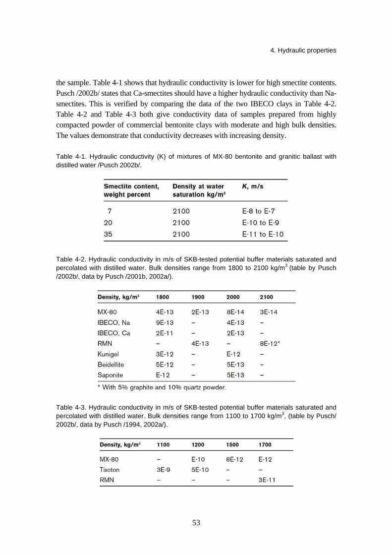
4. Hydraulic properties
53
the sample. Table 4-1 shows that hydraulic conductivity is lower for high smectite contents. Pusch /2002b/ states that Ca-smectites should have a higher hydraulic conductivity than Na-smectites. This is verified by comparing the data of the two IBECO clays in Table 4-2. Table 4-2 and Table 4-3 both give conductivity data of samples prepared from highly compacted powder of commercial bentonite clays with moderate and high bulk densities. The values demonstrate that conductivity decreases with increasing density.
Table 4-1. Hydraulic conductivity (K) of mixtures of MX-80 bentonite and granitic ballast with distilled water /Pusch 2002b/.
Table 4-2. Hydraulic conductivity in m/s of SKB-tested potential buffer materials saturated and percolated with distilled water. Bulk densities range from 1800 to 2100 kg/m3 (table by Pusch /2002b/, data by Pusch /2001b, 2002a/).
Table 4-3. Hydraulic conductivity in m/s of SKB-tested potential buffer materials saturated and percolated with distilled water. Bulk densities range from 1100 to 1700 kg/m3, (table by Pusch/ 2002b/, data by Pusch /1994, 2002a/).

4. Hydraulic properties
54
Pusch /2001b/ has found that heating affects clays in three ways:
1. As illustrated in Table 4-4, the viscosity of the pore water decreases in proportion to the rise in hydraulic conductivity.
2. In clays prepared from highly compacted bentonite powder, the powder grains disintegrate which causes the microstructural homogeneity to improve and the hydraulic conductivity to reduce.
3. At temperatures exceeding around 100 ºC and effective pressures corresponding to the swelling pressure, the average number of interlamellar hydrates appears to drop.
Table 4-4. Example of the influence of temperature on clay prepared from MX-80 powder. The higher conductivity at higher temperature is due to a drop in pore water viscosity. /Pusch 2002b/.
Percolation with salt solutions gives a higher hydraulic conductivity than when electrolyte-poor solutions are used /Pusch 2002b/. The values for MX-80 bentonite and Friedland Ton are presented in Table 4-5. The data shows that at low densities and even when the density at fluid saturation is as high as 1800 kg/m3, the difference is significant. For higher densities, Friedland Ton seems less affected by high pore water salinity than MX-80, which results from mixed-layer clays having higher microstructural stability than pure smectite. In general, it may be noted that hydraulic conductivity increases with higher salinity.
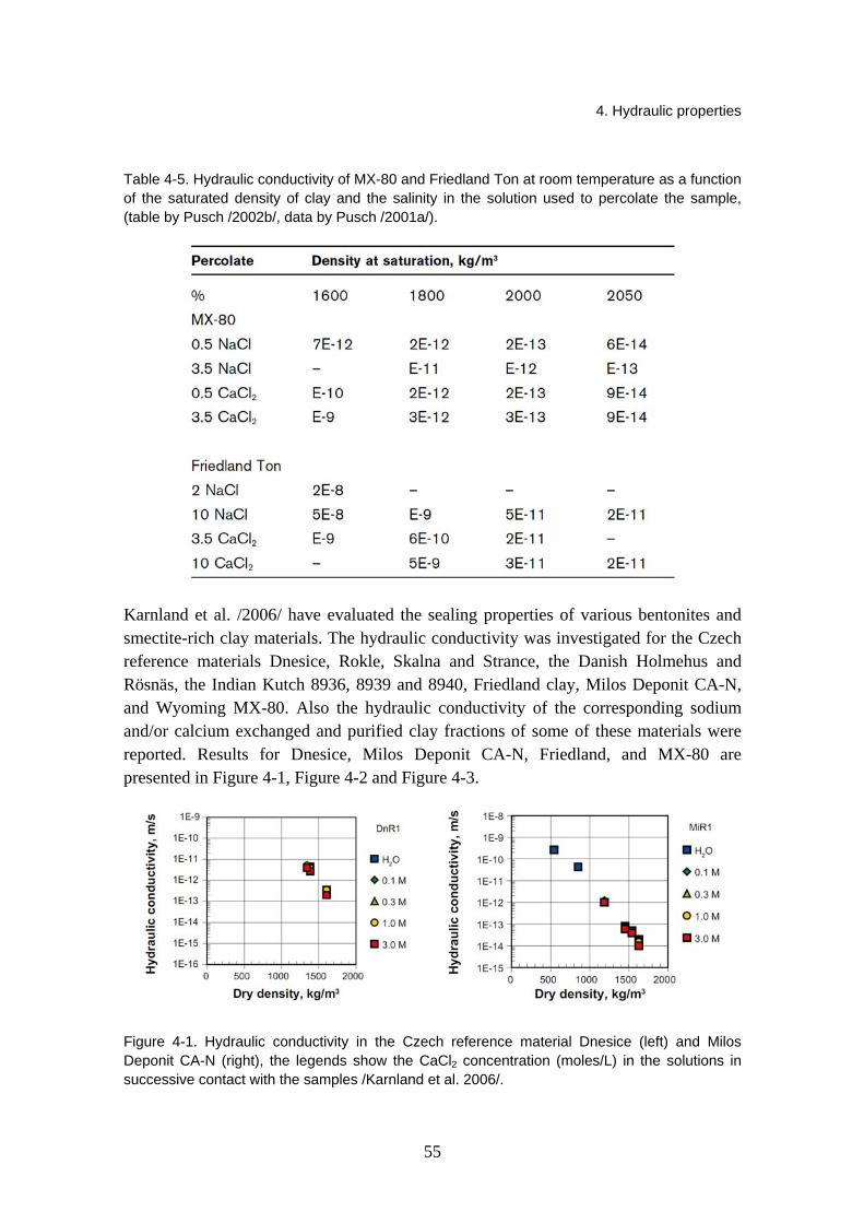
4. Hydraulic properties
55
Table 4-5. Hydraulic conductivity of MX-80 and Friedland Ton at room temperature as a function of the saturated density of clay and the salinity in the solution used to percolate the sample, (table by Pusch /2002b/, data by Pusch /2001a/).
Karnland et al. /2006/ have evaluated the sealing properties of various bentonites and smectite-rich clay materials. The hydraulic conductivity was investigated for the Czech reference materials Dnesice, Rokle, Skalna and Strance, the Danish Holmehus and Rösnäs, the Indian Kutch 8936, 8939 and 8940, Friedland clay, Milos Deponit CA-N, and Wyoming MX-80. Also the hydraulic conductivity of the corresponding sodium and/or calcium exchanged and purified clay fractions of some of these materials were reported. Results for Dnesice, Milos Deponit CA-N, Friedland, and MX-80 are presented in Figure 4-1, Figure 4-2 and Figure 4-3.
Figure 4-1. Hydraulic conductivity in the Czech reference material Dnesice (left) and Milos Deponit CA-N (right), the legends show the CaCl2 concentration (moles/L) in the solutions in successive contact with the samples /Karnland et al. 2006/.
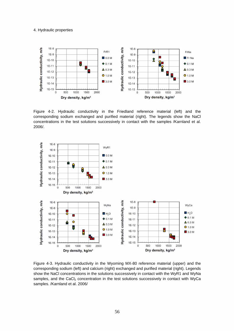
4. Hydraulic properties
56
Figure 4-2. Hydraulic conductivity in the Friedland reference material (left) and the corresponding sodium exchanged and purified material (right). The legends show the NaCl concentrations in the test solutions successively in contact with the samples /Karnland et al. 2006/.
Figure 4-3. Hydraulic conductivity in the Wyoming MX-80 reference material (upper) and the corresponding sodium (left) and calcium (right) exchanged and purified material (right). Legends show the NaCl concentrations in the solutions successively in contact with the WyR1 and WyNa samples, and the CaCl2 concentration in the test solutions successively in contact with WyCa samples. /Karnland et al. 2006/

4. Hydraulic properties
57
One basic demand on repository buffer material and, to a less extent, on tunnel backfilling material is to reduce groundwater flow. The highly compacted high-quality bentonites have a hydraulic conductivity in the range of 1×10–14 to 10–13 m/s. Generally, the hydraulic conductivity increased approximately exponentially with decreasing sample density, and the fact that the product of swelling pressure and hydraulic conductivity is almost constant over a wide range of densities indicates that there is a close relationship in the origin of the two properties /Karnland et al. 2006/. Consequently, the discussion regarding the swelling pressure results by Karnland et al. /2006/ in Section 5.4 has relevance to some extent also for the hydraulic conductivity.
Johannesson and Nilsson /2006/ have measured the hydraulic conductivity of a variety of different backfill materials, including low-grade bentonites Asha 230 and Milos, smectite-rich clays DPJ and Friedland and mixtures containing ballast materials crushed rock or sand and one of the high-grade bentonites MX-80, SPV200 or Deponit CA-N. The tests were conducted in salinities 3.5% and 7%.
The ballast materials that were used for the mixtures were labeled as follows:
1. sand
2. ballast B: crushed rock with maximum grain size 5 mm and with no fine soil
3. ballast C: crushed rock with maximum grain size 5 mm and with about 10–15% content of fine soil.
The results of the tests are presented in Figure 4-4. In general, and the results are in accordance with the hydraulic conductivity of bentonites and smectite-rich clays depending on the smectite-content of the material. The differences between the results for the 30/70 mixtures and for the 40/60 mixture are relatively small, and there is scatter between different 30/70 bentonite/ballast mixtures.
The effect of ballast materials can be studied from the results for the 30/70 mixtures 3, 6 and 7, which contain the same bentonite, but different ballast material. The results for ballast C and sand are better than those for ballast B, since they depict lower hydraulic conductivities. Gunnarsson et al. /2006/ suggest that more data should be made available to verify and explain the effect of ballast material on the properties of the mixture.
The effect of bentonite type is shown in the results for the 30/70 mixtures 1, 2 and 3 with the same ballast material but different bentonite (MX-80, SPV or Deponit CA-N). It seems that the results are a little better for mixtures with Na-bentonite (MX-80 and SPV) than for the mixture 3 with Ca-bentonite (Deponit CA-N). However, when comparing the results for other Ca-bentonite mixtures (6 and 7), the effect is not as clear, possibly because of the compensating effect of the ballast type /Gunnarsson et al. 2006/.
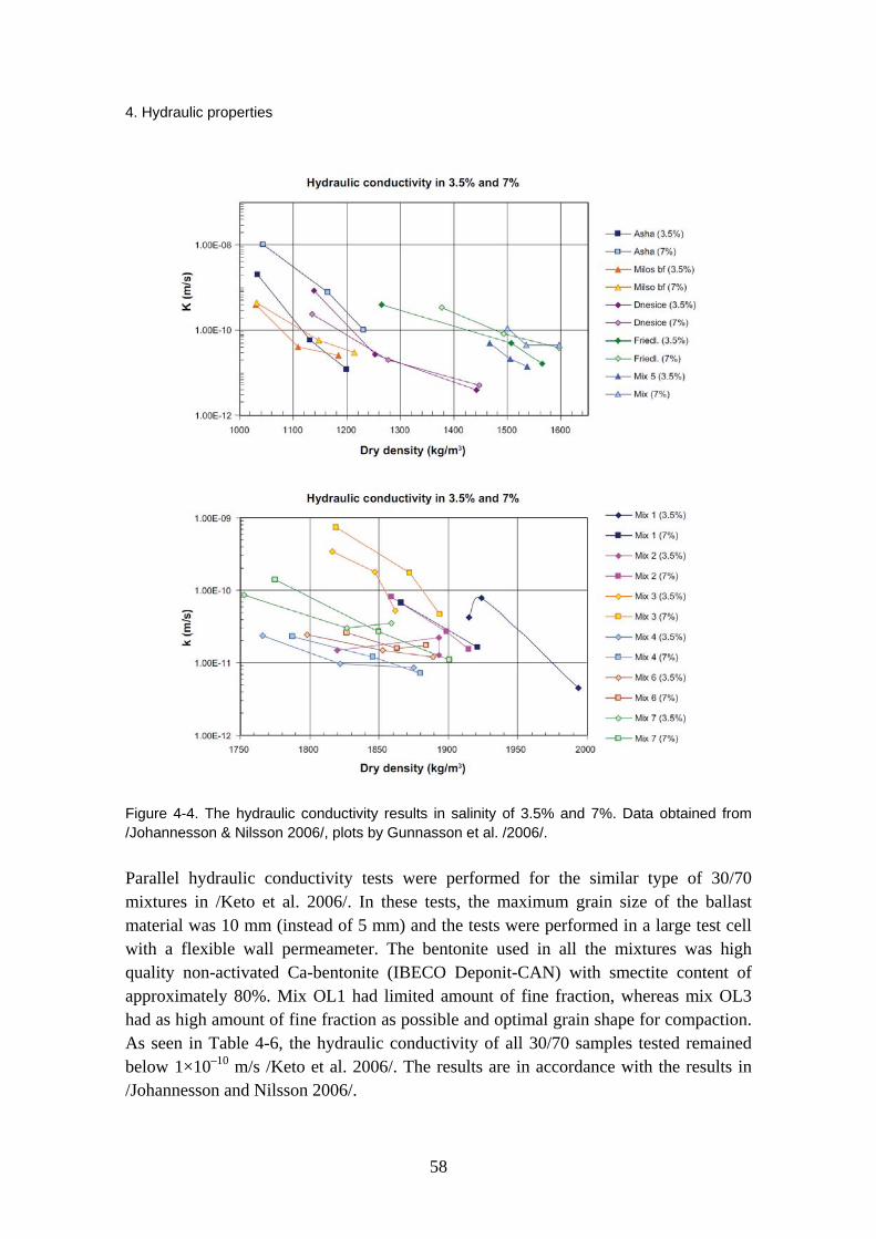
4. Hydraulic properties
58
Figure 4-4. The hydraulic conductivity results in salinity of 3.5% and 7%. Data obtained from /Johannesson & Nilsson 2006/, plots by Gunnasson et al. /2006/.
Parallel hydraulic conductivity tests were performed for the similar type of 30/70 mixtures in /Keto et al. 2006/. In these tests, the maximum grain size of the ballast material was 10 mm (instead of 5 mm) and the tests were performed in a large test cell with a flexible wall permeameter. The bentonite used in all the mixtures was high quality non-activated Ca-bentonite (IBECO Deponit-CAN) with smectite content of approximately 80%. Mix OL1 had limited amount of fine fraction, whereas mix OL3 had as high amount of fine fraction as possible and optimal grain shape for compaction. As seen in Table 4-6, the hydraulic conductivity of all 30/70 samples tested remained below 1×10⁻¹⁰ m/s /Keto et al. 2006/. The results are in accordance with the results in /Johannesson and Nilsson 2006/.

4. Hydraulic properties
59
Table 4-6. Hydraulic conductivity results and test data by Keto et al. /2006/.
Based on the density criteria in Figure 4-5, Gunnarsson et al. /2006/ evaluated that the increase in salinity had the highest effect on Mix 5 (mixture of ballast and bentonite, 50/50), on low-grade bentonite Asha 230 and on Friedland clay. They were unable to explain the effect on Mix 5 with the available data. However, for the other two clays sodium was assumed as the dominant exchangeable cation and, as the water used in the test contained both Ca2+ and Na+ ions in proportion of 50:50, the effect may be due to enhanced ion exchange. From Figure 4-4 it can be seen that the increase in salinity has a distinctive effect on all of the backfill materials, even though the effect of increasing salinity on the density criteria is relatively small and in some cases even reverse. The sensitivity of hydraulic conductivity to the drop in density does not seem to depend heavily on the salinity of the water.
Figure 4-5. The effect of increase in groundwater salinity to the evaluated density criteria concerning hydraulic conductivity < 1E–10 m/s, data by /Johannesson & Nilsson 2006/, figure by Gunnarsson et al. /2006/.

4. Hydraulic properties
60
Johannesson /2008/ has performed additional oedometer tests on three backfilling materials, Asha 230, Friedland clay and 30/70 mixture consisting of IBECO Deponit CA-N Ca-bentonite (30%) and crushed rock (70%), with densities expected in a filling consisting of precompacted blocks. The diameter and the height of the samples were 50 mm and 20 mm, respectively. After compaction in the oedometer to a specified dry density, the samples were saturated from the top and bottom with two different water salinities (3.5% and 7%). After saturation, a pore pressure gradient was applied over the sample and the volume of outflowing water was measured and used for calculating the hydraulic conductivity of the sample.
Table 4-7 shows the evaluated hydraulic conductivity and swelling pressure at the expected dry density. The measured hydraulic conductivity of the Friedland clay is plotted in Figure 4-6 together with results from previous measurements made on samples with lower densities. Corresponding plots for the two other backfill materials are given in the study /Johannesson 2008/.
Table 4-7. Results for hydraulic conductivity and swelling pressure of the different backfill materials. The evaluations are made at expected density of the backfill materials at different water salinity (NaCl:CaCl2, 50:50). /Johannesson 2008/.
The hydraulic conductivities obtained for both types of water at the expected dry density after saturation in a backfilling composed of pre-compacted blocks and pellets were far below 1×10⁻¹⁰ m/s for the three investigated materials.
Values for hydraulic conductivity of sand-bentonite mixtures can also be found in articles by Karnland et al. /2008/, Yamaguchi et al. /2007/, Komine /2004/ (see Section 5.4) and Siemens and Blatz /2007/, who have developed a hydraulic conductivity apparatus for bentonite soils. Karnland et al. /2008/ concluded that mixing with quartz sand in combination with 0.2 M NaCl solution generally lead to a significant decrease in swelling pressure and an increase in hydraulic conductivity, and that the effect on swelling pressure and hydraulic conductivity of a short-term temperature increase to 90 ºC was very limited.
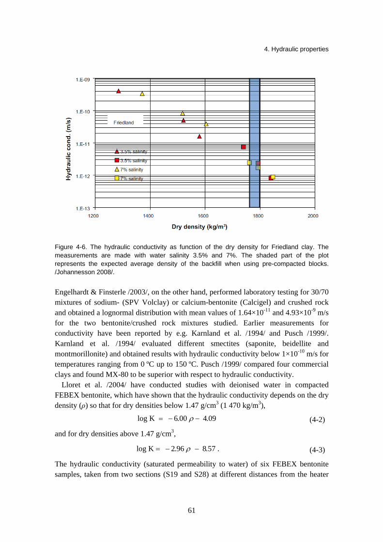
4. Hydraulic properties
61
Figure 4-6. The hydraulic conductivity as function of the dry density for Friedland clay. The measurements are made with water salinity 3.5% and 7%. The shaded part of the plot represents the expected average density of the backfill when using pre-compacted blocks. /Johannesson 2008/.
Engelhardt & Finsterle /2003/, on the other hand, performed laboratory testing for 30/70 mixtures of sodium- (SPV Volclay) or calcium-bentonite (Calcigel) and crushed rock and obtained a lognormal distribution with mean values of 1.64×10⁻¹¹ and 4.93×10⁻⁹ m/s for the two bentonite/crushed rock mixtures studied. Earlier measurements for conductivity have been reported by e.g. Karnland et al. /1994/ and Pusch /1999/. Karnland et al. /1994/ evaluated different smectites (saponite, beidellite and montmorillonite) and obtained results with hydraulic conductivity below 1×10⁻¹⁰ m/s for temperatures ranging from 0 ºC up to 150 ºC. Pusch /1999/ compared four commercial clays and found MX-80 to be superior with respect to hydraulic conductivity.
Lloret et al. /2004/ have conducted studies with deionised water in compacted FEBEX bentonite, which have shown that the hydraulic conductivity depends on the dry density (ρ) so that for dry densities below 1.47 g/cm3 (1 470 kg/m3),
log K 6.00 4.09 ρ= − − (4-2)
and for dry densities above 1.47 g/cm3,
log K 2.96 8.57 .ρ= − − (4-3)
The hydraulic conductivity (saturated permeability to water) of six FEBEX bentonite samples, taken from two sections (S19 and S28) at different distances from the heater

4. Hydraulic properties
62
along a sampling radius, has been determined in the dismantling of the first section of the FEBEX in situ test /Villar & Lloret 2007/. The results obtained are plotted in Figure 4-7 as a function of the position of the sample in the barrier. The hydraulic conductivity is clearly related to dry density and the latter in turn is related to the position of the block in the barrier. However, trimming has caused changes in the dry density of the samples, for which reason dry densities lower than expected are found. It must be pointed out that the values measured do not correspond to the permeability of the bentonite at the moment it was retrieved, since the samples have been saturated to perform the determination, and permeability depends greatly on the degree of saturation and on the pore size distribution changes that occur as a consequence of hydration /Villar & Lloret 2007/.
Figure 4-7. Hydraulic conductivity of samples from sections S19 and S28 (the dry density of the samples is indicated in g/cm3) /Villar & Lloret 2007/.
The values are also plotted in Figure 4-8 as a function of the dry density of the samples along with the empirical correlations for untreated bentonite. The values of the hydraulic conductivity measured for the samples of lower density (more hydrated) are in the order of the expected ones, but for samples of higher densities there is a large dispersion in the values obtained, without any clear tendency. The hydraulic conductivity measurements performed in samples retrieved from in situ tests have not shown any important variation of this property of the bentonite after being under repository conditions.
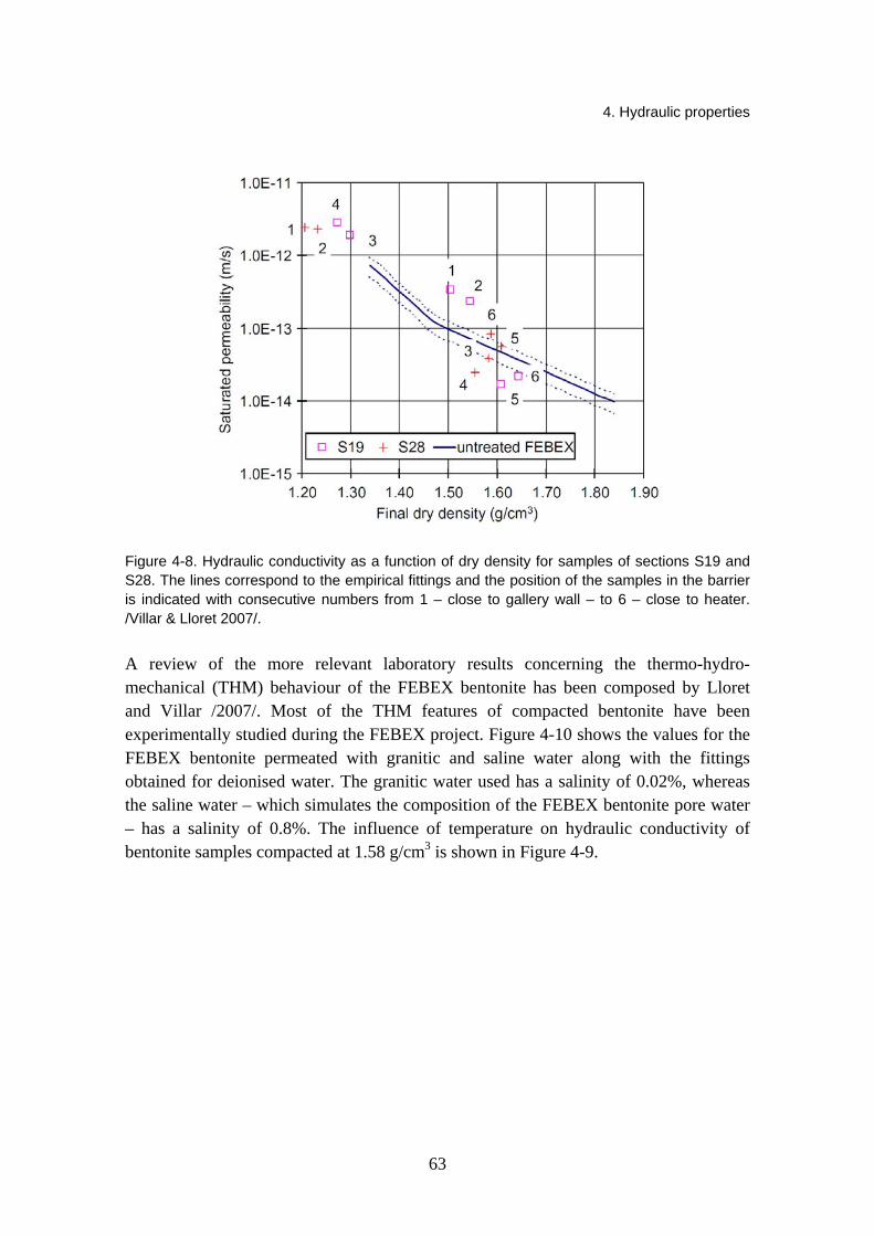
4. Hydraulic properties
63
Figure 4-8. Hydraulic conductivity as a function of dry density for samples of sections S19 and S28. The lines correspond to the empirical fittings and the position of the samples in the barrier is indicated with consecutive numbers from 1 – close to gallery wall – to 6 – close to heater. /Villar & Lloret 2007/.
A review of the more relevant laboratory results concerning the thermo-hydro-mechanical (THM) behaviour of the FEBEX bentonite has been composed by Lloret and Villar /2007/. Most of the THM features of compacted bentonite have been experimentally studied during the FEBEX project. Figure 4-10 shows the values for the FEBEX bentonite permeated with granitic and saline water along with the fittings obtained for deionised water. The granitic water used has a salinity of 0.02%, whereas the saline water – which simulates the composition of the FEBEX bentonite pore water – has a salinity of 0.8%. The influence of temperature on hydraulic conductivity of bentonite samples compacted at 1.58 g/cm3 is shown in Figure 4-9.

4. Hydraulic properties
64
Figure 4-9. Temperature influence on hydraulic conductivity of bentonite compacted at dry density of 1.58 g/cm3 (the error bar corresponds to samples tested at laboratory temperature) /Villar & Lloret 2004/.
Figure 4-10. Hydraulic conductivity for granitic and saline water vs. dry density of the FEBEX clay and fittings obtained for deionised water /Villar 2002/.
4. Hydraulic properties
65
Lloret and Villar /2007/ concluded that the temperature effects on hydraulic conductivity are small, and the hydraulic conductivity of bentonite increases when saline water is used instead of deionised water as the permeating agent.
Börgesson et al. /2001/ have determined the hydraulic conductivity of the bentonite OT-9607 used in the THM experiment at Kamaishi mine in Japan. The hydraulic conductivity of the water saturated buffer material was measured at a dry density of 1.65 g/cm3
in an oedometer at different temperatures. Three samples of 0.5 cm in thickness and 5 cm in diameter were exposed to a hydraulic gradient and the flow of water through the samples was measured. The hydraulic conductivity was calculated with Darcy's law. The results showed that the influence of the temperature was almost completely on the change in viscosity of the water and that the intrinsic permeability is constant. The measured average value of the intrinsic permeability is k = 1.6×10⁻²⁰
m2, which yields a hydraulic conductivity of K = 3.3×10⁻¹³
m/s at 60 °C. To assist the KENTEX experiment, laboratory experiments were conducted to
determine the thermal and hydraulic properties of the bentonite buffer /Cho et al. 2009/. The hydraulic conductivities of the bentonite with dry densities of 1.4 Mg/m3, 1.6 Mg/m3, and 1.8 Mg/m3 were measured at 25 °C. The bentonite was uniaxially compacted to the desired density in a cylindrical cell which had an inside diameter of 50 mm and a height of 25 mm or 10 mm depending on the dry density. The water was supplied from the bottom to the top of the chamber at a hydraulic pressure of 9 to 20 bars. As with studies previously presented in this chapter, the hydraulic conductivities for Kyungju Ca-bentonite were also found to decrease with an increasing dry density of the bentonite (Figure 4-11). The hydraulic conductivities of the compacted bentonite at a temperature of 80 °C were up to approximately 3 times compared to those at 20 °C /Cho et al. 1999/. The change of the hydraulic conductivities in the bentonite at elevated temperatures is attributable to the changes in the viscosity and the density of the water, and the effect of the change in the permeability is negligible /Cho et al. 1999/. The temperatures in the KENTEX experiment range from 25 °C–90 °C. Therefore the permeability of the compacted bentonite is assumed to be constant under the KENTEX experimental condition /Cho et al. 2009/.
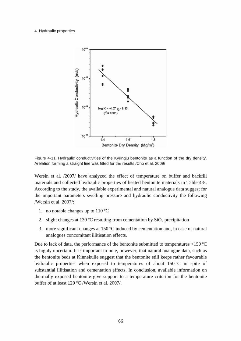
4. Hydraulic properties
66
Figure 4-11. Hydraulic conductivities of the Kyungju bentonite as a function of the dry density. Arelation forming a straight line was fitted for the results./Cho et al. 2009/
Wersin et al. /2007/ have analyzed the effect of temperature on buffer and backfill materials and collected hydraulic properties of heated bentonite materials in Table 4-8. According to the study, the available experimental and natural analogue data suggest for the important parameters swelling pressure and hydraulic conductivity the following /Wersin et al. 2007/:
1. no notable changes up to 110 ºC
2. slight changes at 130 ºC resulting from cementation by SiO2 precipitation
3. more significant changes at 150 ºC induced by cementation and, in case of natural analogues concomitant illitisation effects.
Due to lack of data, the performance of the bentonite submitted to temperatures >150 ºC is highly uncertain. It is important to note, however, that natural analogue data, such as the bentonite beds at Kinnekulle suggest that the bentonite still keeps rather favourable hydraulic properties when exposed to temperatures of about 150 ºC in spite of substantial illitisation and cementation effects. In conclusion, available information on thermally exposed bentonite give support to a temperature criterion for the bentonite buffer of at least 120 ºC /Wersin et al. 2007/.
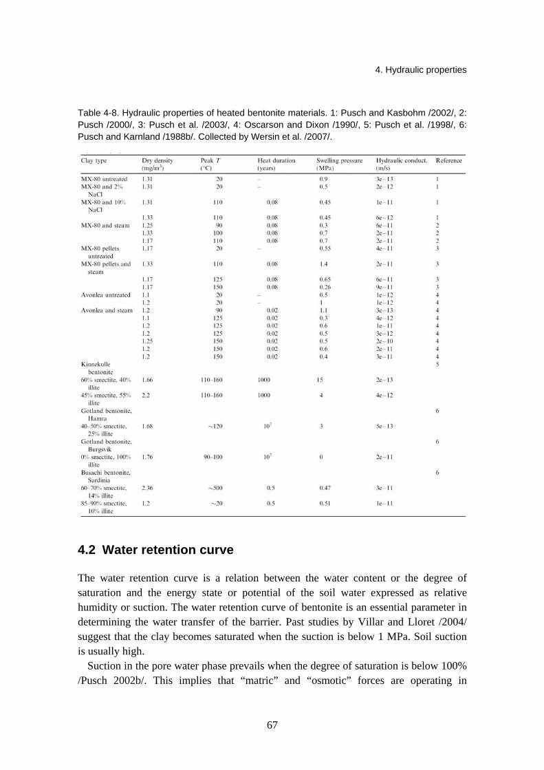
4. Hydraulic properties
67
Table 4-8. Hydraulic properties of heated bentonite materials. 1: Pusch and Kasbohm /2002/, 2: Pusch /2000/, 3: Pusch et al. /2003/, 4: Oscarson and Dixon /1990/, 5: Pusch et al. /1998/, 6: Pusch and Karnland /1988b/. Collected by Wersin et al. /2007/.
4.2 Water retention curve
The water retention curve is a relation between the water content or the degree of saturation and the energy state or potential of the soil water expressed as relative humidity or suction. The water retention curve of bentonite is an essential parameter in determining the water transfer of the barrier. Past studies by Villar and Lloret /2004/ suggest that the clay becomes saturated when the suction is below 1 MPa. Soil suction is usually high.
Suction in the pore water phase prevails when the degree of saturation is below 100% /Pusch 2002b/. This implies that “matric” and “osmotic” forces are operating in

4. Hydraulic properties
68
clay/water systems. When the degree of water saturation rises above 95%, the suction becomes insignificant. According to Pusch /2002b/, suction is largely independent of the density. Suction can be calculated from the Kelvin equation,
0
· - ln( )·w v s
R T pp
ψν ω
= (4-4)
where ψ = suction (kPa) T = absolute temperature (K) R = universal gas constant (8.31432 J/(mol K)) νw0 = specific volume of water (1/ρw m3/kg) ρw = density of water (kg/m3) ωv = molecular mass of water vapour (18 kg/kmol) p = partial pressure of pore-water vapour (kPa)
ps = saturation pressure of water vapour over a flat surface of pure water of the same temperature (kPa).
The relative humidity RH is the ratio between the partial vapour pressure p and the vapour pressure at saturation ps in %,
100·s
pRHp
= . (4-5)
A laboratory programme has been carried out by Dueck /2004, 2008/ with the purpose of improving both the general understanding and the available models of the hydro-mechanical behaviour of unsaturated, swelling bentonite. The retention properties were studied with the following different boundary conditions: free swelling, constant volume and constant water content. In this study, the term retention curve indicated the relationship between relative humidity RH and water content w. The material used in the investigation was MX-80 bentonite. The retention curve under free swelling conditions was determined by an experimental simple method using glass jars, and by a sorption balance. In the first method, a sample with a dry weight of approximately 10 g is placed in a pan above a salt solution and the sample is maintained at a fixed humidity throughout the test. In the second method, a sample with a dry weight of about 15 mg is placed on a micro-balance and the sample is exposed to a continuous flow of air at a predetermined relative humidity at 25 °C.
Figure 4-12 shows the retention curves from the method with glass jars representing four initial water contents (wini = 0, 7.5, 17.5 and 27%). The retention curves have different appearances depending on the initial water content. It is proposed that a curve representing the initial water content wini = 0% is called the basic retention curve, and that retention curves determined at deviating initial water contents are called the specific retention curves. Both the basic curve and the specific curves represent no-load
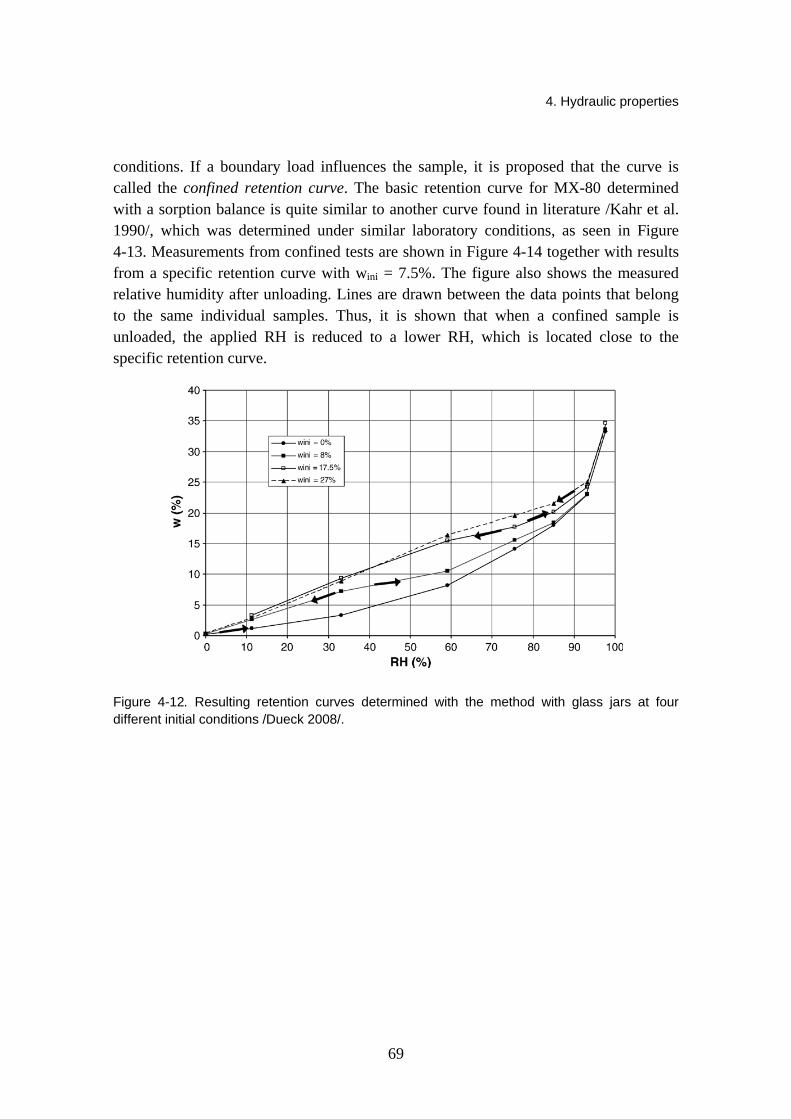
4. Hydraulic properties
69
conditions. If a boundary load influences the sample, it is proposed that the curve is called the confined retention curve. The basic retention curve for MX-80 determined with a sorption balance is quite similar to another curve found in literature /Kahr et al. 1990/, which was determined under similar laboratory conditions, as seen in Figure 4-13. Measurements from confined tests are shown in Figure 4-14 together with results from a specific retention curve with wini = 7.5%. The figure also shows the measured relative humidity after unloading. Lines are drawn between the data points that belong to the same individual samples. Thus, it is shown that when a confined sample is unloaded, the applied RH is reduced to a lower RH, which is located close to the specific retention curve.
Figure 4-12. Resulting retention curves determined with the method with glass jars at four different initial conditions /Dueck 2008/.
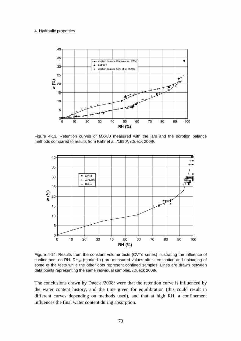
4. Hydraulic properties
70
Figure 4-13. Retention curves of MX-80 measured with the jars and the sorption balance methods compared to results from Kahr et al. /1990/, /Dueck 2008/.
Figure 4-14. Results from the constant volume tests (CVTd series) illustrating the influence of confinement on RH. RHun (marked +) are measured values after termination and unloading of some of the tests while the other dots represent confined samples. Lines are drawn between data points representing the same individual samples. /Dueck 2008/.
The conclusions drawn by Dueck /2008/ were that the retention curve is influenced by the water content history, and the time given for equilibration (this could result in different curves depending on methods used), and that at high RH, a confinement influences the final water content during absorption.

4. Hydraulic properties
71
Tang and Cui /2006/ have studied the water retention properties of compacted MX-80 bentonite using vapour equilibrium techniques for high values of suction. Five salts were used in the study. Samples were compacted and tests were performed at 20, 40, 60 and 80ºC. The final water contents were eventually plotted versus the logarithm of suction in Figure 4-15. The increase in temperature shifted the curve downwards, which means that a decrease of the water retention capacity of soil occurred with heating. The results were in good agreement with previously obtained results by e.g. Villar and Lloret /2004/. It was also deduced by Tang and Cui /2006/ that the water exchange rate between solution and soil samples was more important at higher exposition surface of the solution, with bigger samples, or with air circulation. In addition, the effects of mineralogy and hydraulic history were observed. It appeared that the techniques used had negligible effect on the water retention curves.
Figure 4-15. Water retention curves at different temperatures /Tang and Cui 2005/.
The effect of temperature on the water retention capacity of FEBEX and MX-80 bentonites has been further explored by Villar and Gómez-Espina /2008/. They expanded the range of studied temperatures to between 20 and 120 ºC. The bentonites were compacted at dry densities from 1.3 to 1.8 g/cm3, and the retention curves were determined from samples in their natural state (without previous drying or grinding), kept at constant volume during the determination. The water retention capacity of the bentonite decreased clearly with temperature, especially when it was above 60 ºC and

4. Hydraulic properties
72
when the density of the bentonite was high. This decrease could not be explained on the basis of the changes of water surface tension with temperature. Instead, mechanisms related to the physico-chemical interactions that occur at microscopic level seemed to explain qualitatively the experimental observations /Villar & Gómez-Espina 2008/.
According to Villar and Gómez-Espina /2008/, the effect of density on the retention capacity varied according to the suction range of 0 to 200 MPa. For suctions below a threshold value (about 12–20 MPa) for a given water content and temperature, the suction of the higher density samples was lower, and above this suction value the trend inverted. The effect of dry density on the water retention capacity seemed lower than that of temperature. Differences between the two tested materials also existed: The FEBEX bentonite, which has mainly bivalent cations in the exchange complex, had a higher retention capacity than the MX-80 bentonite, which is predominantly sodic. Particularly for MX-80 bentonite, hysteresis on heating/cooling cycles was observed. Also, the effect of temperature on the water retention capacity was more evident for the FEBEX bentonite.
Three isotropic compression tests at constant water content and with monitoring of the total suction have been performed on compacted expansive MX-80 clay /Tang et al. 2008/. The results showed a slight increase in total suction (s) in the beginning followed by a decrease when the pressure (p) was increased. The initial suction increase was suggested to result from the non saturation of the micropores of the compacted samples: with mechanical compression, the micropore size was decreased, approaching the clay particles and thus resulting in an osmotic suction increase. For the suction decreasing part, a linear s-p relationship was observed with a slope ds/dp varying from −0.30 to −0.46. For the water retention curves obtained it was observed that the curves are influenced by various aspects, such as hysteresis, void ratio and initial state /Tang et al. 2008/.
Johannesson et al. /2008/ have investigated the wetting and homogenization processes occurring in backfill materials: Asha 230 and Friedland clay for use as block materials and Cebogel QSE, MX-80, Minelco and Friedland clay for use as pellets material. The retention curve is here presented as water content versus relative humidity. The specific retention curve was determined for Asha and Friedland materials. The specimens were placed in jars with tight lids at different controlled RH for about 3 months or until a steady state equilibrium was reached. The jars were placed in an oven with a constant temperature of 25 ºC. The retention curves for the Asha and Friedland materials obtained at 25 °C are presented in Figure 4-16. In this figure, results for MX-80 /Dueck & Nilsson 2008/ are also shown for comparison. The initial water content of the Asha 230 material was 1.5% and the Friedland clay 7.8%. The MX-80 material had a water content of 9.8%, the determination was made at 20 ºC and the results were obtained with the same methodology as was used for the materials Asha and Friedland.
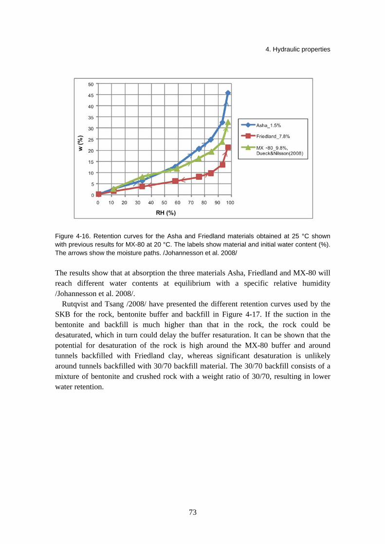
4. Hydraulic properties
73
Figure 4-16. Retention curves for the Asha and Friedland materials obtained at 25 °C shown with previous results for MX-80 at 20 °C. The labels show material and initial water content (%). The arrows show the moisture paths. /Johannesson et al. 2008/
The results show that at absorption the three materials Asha, Friedland and MX-80 will reach different water contents at equilibrium with a specific relative humidity /Johannesson et al. 2008/.
Rutqvist and Tsang /2008/ have presented the different retention curves used by the SKB for the rock, bentonite buffer and backfill in Figure 4-17. If the suction in the bentonite and backfill is much higher than that in the rock, the rock could be desaturated, which in turn could delay the buffer resaturation. It can be shown that the potential for desaturation of the rock is high around the MX-80 buffer and around tunnels backfilled with Friedland clay, whereas significant desaturation is unlikely around tunnels backfilled with 30/70 backfill material. The 30/70 backfill consists of a mixture of bentonite and crushed rock with a weight ratio of 30/70, resulting in lower water retention.
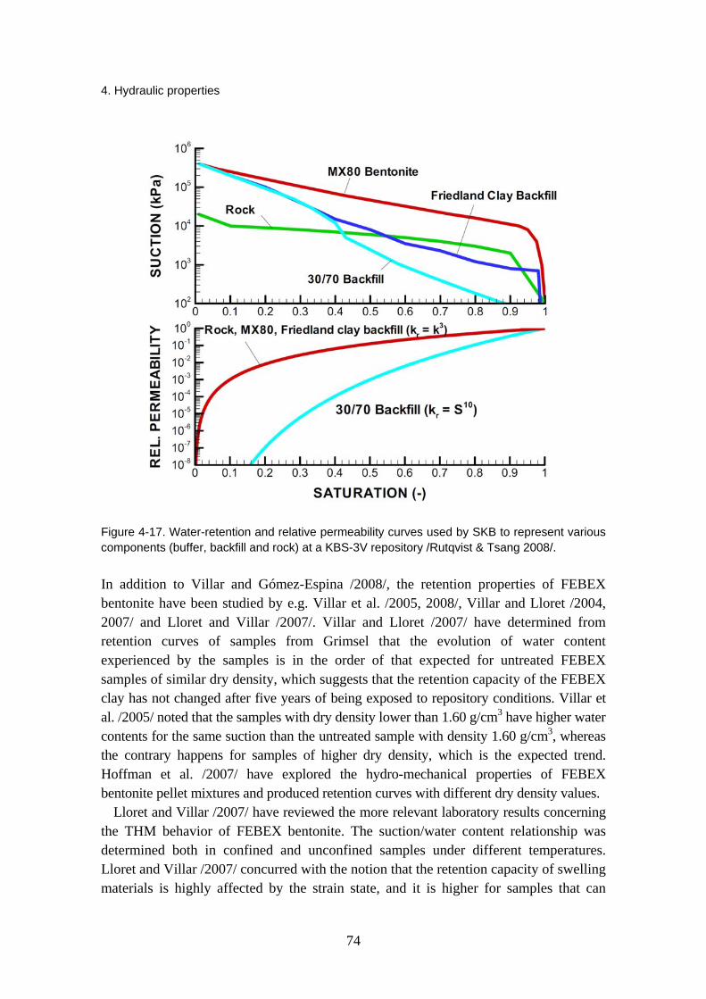
4. Hydraulic properties
74
Figure 4-17. Water-retention and relative permeability curves used by SKB to represent various components (buffer, backfill and rock) at a KBS-3V repository /Rutqvist & Tsang 2008/.
In addition to Villar and Gómez-Espina /2008/, the retention properties of FEBEX bentonite have been studied by e.g. Villar et al. /2005, 2008/, Villar and Lloret /2004, 2007/ and Lloret and Villar /2007/. Villar and Lloret /2007/ have determined from retention curves of samples from Grimsel that the evolution of water content experienced by the samples is in the order of that expected for untreated FEBEX samples of similar dry density, which suggests that the retention capacity of the FEBEX clay has not changed after five years of being exposed to repository conditions. Villar et al. /2005/ noted that the samples with dry density lower than 1.60 g/cm3 have higher water contents for the same suction than the untreated sample with density 1.60 g/cm3, whereas the contrary happens for samples of higher dry density, which is the expected trend. Hoffman et al. /2007/ have explored the hydro-mechanical properties of FEBEX bentonite pellet mixtures and produced retention curves with different dry density values.
Lloret and Villar /2007/ have reviewed the more relevant laboratory results concerning the THM behavior of FEBEX bentonite. The suction/water content relationship was determined both in confined and unconfined samples under different temperatures. Lloret and Villar /2007/ concurred with the notion that the retention capacity of swelling materials is highly affected by the strain state, and it is higher for samples that can

4. Hydraulic properties
75
freely swell (unconfined samples) than for those kept at constant volume. Although the sealing material will be unconfined only in the outer part of the barrier, where a void exists between compacted blocks and host rock, the determination of the suction/water content relationship in unconfined samples is justified because, being much easier to determine, it will still be useful in identifying the influence of temperature. Besides, since the control of volume change in drying paths of the retention curve is difficult, the drying paths at different temperatures are being performed following the standard procedure (free volume).
The retention curve at constant volume, following a wetting/drying path, was determined at different temperatures for different dry densities. The curves followed a wetting path, from suction 130 MPa to 1 MPa, and afterwards, a drying path to 130 MPa. The initial water content of the samples was the hygroscopic one (about 14 wt%). To hinder the swelling of the clay during the determination, the samples were compacted and tested in perforated isochoric cells. These cells were introduced in vacuum desiccators that were, in turn, placed into ovens at controlled temperature. The relative humidity inside the desiccators was controlled by sulphuric acid solutions of different concentrations.
The results obtained showed the hysteretic behavior of the clay. For the same suction, the water contents reached during drying paths were higher than those obtained during the previous wetting. In addition, the retention capacity at higher temperature was slightly lower, as can be observed in Figure 4-18.
Figure 4-19 shows the comparison of the water retention curves obtained at different dry densities under confined and unconfined conditions. It can be observed that the suction- water content relationship is independent of dry density if the water content is lower than a value of about 20%. This may be explained taking into account that this value corresponds to the maximum water content that can be retained in the intra-aggregates pores, where the total porosity is not very relevant /Romero et al. 1999/. However, near saturation the differences in terms of water content are significant due to the large increment of pore volume experienced by the bentonite during the hydration under unconfined conditions.

4. Hydraulic properties
76
Figure 4-18. Water retention curves at different temperatures and for different bentonite densities under confined conditions. /Lloret & Villar 2007/
Figure 4-19. Comparison of the retention curves obtained for the FEBEX bentonite in confined and unconfined volume conditions. /Lloret & Villar 2007/

4. Hydraulic properties
77
Börgesson et al. /2001/ have measured the water potential or negative water pressure of the water unsaturated OT-9607 bentonite as a function of the water ratio and the temperature. The measurements were made under both drying and wetting of unconfined samples placed in small chambers equipped with thermocouple psychrometers. The results of the measurements are shown in Figure 4-20.
Figure 4-20. Water retention curve of the bentonite OT-9607 /Börgesson et al. 2001/.
In the KENTEX laboratory tests, a water retention curve was defined for the Kyungju Ca-bentonite as the relation between the water potential head h and the volumetric water content θ /Cho et al. 2009/. The water potential of the bentonite with a dry density of 1.5 Mg/m3
and varying water contents was measured using a commercial sample chamber and a water potential system. The bentonite was uniaxially compacted to the desired density in a stainless steel sample chamber, which was enclosed in a insulation module to provide an uniform temperature of the sample and chamber. The measurement was conducted in two manners: the single step procedure for the water contents beyond 10% and the two-step procedure for the water content range of 3% to 10%. The relation is shown in Figure 4-21 and it indicates that the osmotic potential of the compacted bentonite is high.
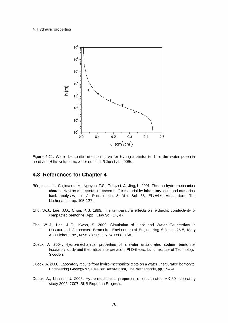
4. Hydraulic properties
78
Figure 4-21. Water–bentonite retention curve for Kyungju bentonite. h is the water potential head and θ the volumetric water content. /Cho et al. 2009/.
4.3 References for Chapter 4
Börgesson, L., Chijimatsu, M., Nguyen, T.S., Rutqvist, J., Jing, L. 2001. Thermo-hydro-mechanical characterization of a bentonite-based buffer material by laboratory tests and numerical back analyses, Int. J. Rock mech. & Min. Sci. 38, Elsevier, Amsterdam, The Netherlands, pp. 105-127.
Cho, W.J., Lee, J.O., Chun, K.S. 1999. The temperature effects on hydraulic conductivity of compacted bentonite, Appl. Clay Sci. 14, 47.
Cho, W.-J., Lee, J.-O., Kwon, S. 2009. Simulation of Heat and Water Counterflow in Unsaturated Compacted Bentonite, Environmental Engineering Science 26-5, Mary Ann Liebert, Inc., New Rochelle, New York, USA.
Dueck, A. 2004. Hydro-mechanical properties of a water unsaturated sodium bentonite, laboratory study and theoretical interpretation. PhD-thesis, Lund Institute of Technology, Sweden.
Dueck, A. 2008. Laboratory results from hydro-mechanical tests on a water unsaturated bentonite, Engineering Geology 97, Elsevier, Amsterdam, The Netherlands, pp. 15–24.
Dueck, A., Nilsson, U. 2008. Hydro-mechanical properties of unsaturated MX-80, laboratory study 2005–2007. SKB Report in Progress.
4. Hydraulic properties
79
Engelhardt, I., Finsterle, S. 2003. Thermal-Hydraulic Experiments with Bentonite/Crushed Rock Mixtures and Estimation of Effective Parameters by Inverse Modeling. – Applied Clay Science 23, pp. 111–120.
Gunnarsson, D., Morén, L., Sellin, P., Keto, P. 2006. Deep repository – engineered barrier systems. Assesment of backfill materials and methods for deposition tunnels, R-06-71, SKB, Stockholm, Sweden, 52 p.
Hedin, A., Andersson, J., Skagius, K., Pers, K., Spahiu, K., Werme, L., Sellin, P., Selroos, J.-O., Munier, R., Puigdomenech, I., Morén, L., Kautsky, U., Näslund, J.-O., Vahlund, F. 2006. Long-term safety for KBS-3 repositories at Forsmark and Laxemar – a first evaluation. Main Report of the SR-Can project, SKB TR-06-09, SKB, Stockholm, Sweden.
Hoffmann, C., Alonso, E.E., Romero, E. 2007. Hydro-mechanical behaviour of bentonite pellet mixtures, Physics and Chemistry of the Earth 32, Elsevier, Amsterdam, The Netherlands, pp. 832–849.
Johannesson, L.-E. 2008. Backfilling and closure of the deep repository - Phase 3 pilot test to verify engineering feasibility, Geotechnical investigations made on unsaturated backfill materials, SKB R-08-131, SKB, Stockholm, Sweden, 27 p.
Johannesson, L.-E., Nilsson, U. 2006. Deep repository – Engineered barrier system. Geotechnical properties of candidate backfill materials. Laboratory tests and calculations for determining performance, SKB R-06-73, SKB, Stockholm, Sweden.
Johannesson, L.-E., Sandén, T., Dueck, A. 2008. Deep repository – engineered barrier system. Wetting and homogenization processes in backfill materials. Laboratory tests for evaluating modeling parameters, SKB R-08-136, SKB, Stockholm, Sweden.
Kahr, G., Kraehenbuehl, F., Stoeckli, H.F., Müller-Vonmoos, M. 1990. Study of the water–bentonite system by vapour adsorption, immersion calorimetry and X-ray techniques: II. Heats of immersion, swelling pressures and thermodynamic properties. Clay Minerals 25, pp. 499–506.
Karnland, O., Pusch, R., Sandén, T. 1994. Buffer material characterisation, SKB AR-94-60, SKB, Stockholm, Sweden (in Swedish).
Karnland, O., Olsson, S., Nilsson, U. 2006. Mineralogy and sealing properties of various bentonites and smectite-rich clay materials, SKB 2006, TR-06-30, Stockholm, Sweden, 70 p.
Karnland, O., Nilsson, U., Weber, H., Wersin, P. 2008. Sealing ability of Wyoming bentonite pellets foreseen as buffer material – Laboratory results, Physics and Chemistry of the Earth 33, Elsevier, Amsterdam, The Netherlands, pp. 472–S475.
Keto, P., Kuula-Väisänen, P., Ruuskanen, J. 2006. Effect of material parameters on the compactibility of backfill materials. Posiva Working Report 2006-34, Posiva Oy, Eurajoki, Finland.
4. Hydraulic properties
80
Komine, H. 2004. Simplified evaluation on hydraulic conductivities of sand-bentonite mixture backfill, Elsevier, Applied Clay Science Vol. 26, Amsterdam, The Netherlands, pp. 13–19.
Lloret, A., Romero, E., Villar, M.V. 2004. FEBEX II project final report on thermo-hydro-mechanical laboratory tests, Publicación Técnica ENRESA 10/04, Madrid, Spain, 180 p.
Lloret, A., Villar, M.V. 2007. Advances on the knowledge of the thermo-hydro-mechanical behaviour of heavily compacted ‘‘FEBEX’’ bentonite, Physics and Chemistry of the Earth 32, Elsevier, Amsterdam, The Netherlands, pp. 701–715.
Oscarson, D.W., Dixon, D.A. 1990. Effect of heating unsaturated bentonite on the swelling and hydraulic properties of subsequently saturated clay. In Proc. of the Annual Conf. and 1st Biennial Environmental Speciality Conf. of the Canadian Soc. of Civil Engineering, Hamilton, Ontario, Vol. II-1, pp. 312–323.
Pastina, B., Hellä, P. 2006. Expected evolution of a spent fuel repository at Olkiluoto. POSIVA 2006–05. Posiva Oy, Olkiluoto, Finland.
Pusch, R., Karnland, O. 1988. Geological evidence of smectite longevity. The Sardinian and Gotland cases. SKB Technical Report 88-26, Stockholm, Sweden, 60 p.
Pusch, R. 1994. Waste Disposal in Rock. Developments in Geotechnical Engineering, 76. Elsevier Publ. Co.
Pusch, R., Takase, H., Benbow, S. 1998. Chemical processes causing cementation in heat-affected smectite – the Kinnekulle bentonite. SKB Technical Report TR-98-25, Stockholm, Sweden, 56 p.
Pusch, R. 1999. Is montmorillonite-rich clay of MX-80 type the ideal buffer for isolation of HLW?, SKB TR-99-33, SKB, Stockholm, Sweden.
Pusch, R. 2000. On the effect of hot water vapor on MX-80 clay. SKB Technical Report TR-00-16, Stockholm, Sweden, 41 p.
Pusch, R. 2001a. Experimental study of the effect of high porewater salinity on the physical properties of a natural smectitic clay. SKB TR-01-07 SKB, Stockholm, Sweden.
Pusch, R. 2001b. The microstructure of MX-80 clay with respect to its bulk physical properties under different environmental conditions. SKB TR-01-08, SKB, Stockholm, Sweden.
Pusch, R. 2002a. Physical properties of Czech buffer candidate RMN. SKB Technical Report (in print).
Pusch, R. 2002b. The buffer and backfill handbook. Part 2: Materials and techniques, SKB TR-02-12, SKB, Stockholm, Sweden.
Pusch, R., Bluemling, P., Johnson, L.H. 2003. Performance of strongly compressed MX-80 pellets under repository-like conditions. Appl. Clay Sci. 23, pp. 239–244.
Pusch, R., Kasbohm, J. 2002. Alteration of MX-80 by hydrothermal treatment under high salt content conditions. SKB Technical Report TR-02-06, Stockholm, Sweden, 44 p.

4. Hydraulic properties
81
Romero, E., Gens, A., Lloret, A. 1999. Water permeability, water retention and microstructure of unsaturated Boom clay. Eng. Geol. 54, pp. 117–127.
Rutqvist, J., Tsang, C.F. 2008. Review of SKB’s work on coupled THM processes within SR-Can: external review contribution in support of SKI’s and SSI’s review of SR-Can, SKI report, 2008:08, SKI, Stockholm, Sweden.
Siemens, G.A., Blatz, J.A. 2007. A hydraulic conductivity apparatus for deformable materials, Canadian Geotechnical Journal 44-8, Ottawa, Canada, pp. 997–1005.
Tang, A.M., Cui, Y.J. 2005. Controlling suction by the vapour equilibrium technique at different temperatures and its application in determining the water retention properties of MX80 clay, Canadian Geotechnical Journal 42(1), Ottawa, Canada, pp. 287–296.
Tang, A.M., Cui, Y.J. 2006. Use of saturated saline solutions in determining the water retention curve of compacted bentonite at different temperatures, Unsaturated Soils 2006, Reston, Virginia, USA.
Tang, A.M., Cui, Y.J., Barnel, N. 2008. Compression-induced suction change in a compacted expansive clay, Unsaturated Soils, Advances in Geo-Engineering, London, UK.
Yamaguchi, T., Sakamoto, Y., Akai, M., Takazawa, M., Iida, Y., Tanaka, T., Nakayama, S. 2007. Experimental and modeling study on long-term alteration of compacted bentonite with alkaline groundwater, Physics and Chemistry of the Earth 32, Elsevier, Amsterdam, The Netherlands, pp. 298–310.
Villar, M.V. 2002. Thermo-hydro-mechanical characterisation of a bentonite from Cabo de Gata. A study applied to the use of bentonite as sealing material in high level radioactive waste repositories. Publicación Técnica ENRESA 01/2002, Madrid, 258 p.
Villar, V.M., Lloret, A. 2004. Influence of temperature on the hydro-mechanical behaviour of a compacted bentonite, Elsevier, Applied Clay Science Vol. 26, Amsterdam, The Netherlands, pp. 337–350.
Villar, M.V., García-Siñeriz, J.L., I. Bárcena, I., Lloret, A. 2005. State of the bentonite barrier after five years operation of an in situ test simulating a high level radioactive waste repository, Engineering Geology 80, Elsevier, Amsterdam, The Netherlands, pp. 175–198.
Villar, M.V., Lloret, A. 2007. Dismantling of the first section of the FEBEX in situ test: THM laboratory tests on the bentonite blocks retrieved, Elsevier 2007, Physics and Chemistry of the Earth Vol. 32, Amsterdam, The Netherlands, pp. 716–729.
Villar, M.V., Gómez-Espina, R. 2008. Effect of temperature on the water retention capacity of FEBEX and MX-80 bentonites, Unsaturated Soils, Advances in Geo-Engineering, London, UK.
Wersin, P., Johnson, L.H., McKinley, I.G. 2007. Performance of the bentonite barrier at temperatures beyond 100 ºC: A critical review, Physics and Chemistry of the Earth 32, Elsevier, Amsterdam, The Netherlands, pp.780–788.
5. Mechanical properties
82
5. Mechanical properties
5.1 Strength properties
The strength properties for different buffer materials have been defined in Clay Technology AB in several studies. The summary of the results have been presented by Börgesson et al. /1995/. They have defined the Mohr-Coulomb’s strength parameters friction angle φ (°) and cohesion c (kPa). The studied materials have not been specified very detailed. The studied materials were
• natural Na-bentonite (MX-80) • natural Na-bentonite from Wyoming (SPV200) • natural Ca-bentonite (Moosburg) • Na-bentonite converted from Ca-bentonite (IBECO) • French reference buffer material.
The tests included standard loading procedure and so called passive triaxial tests, where the axial loading pressure has been decreased. The tests have been conducted in the room temperature and in a nearly saturated state. Both drained and undrained test types have been conducted. A couple of tests have been conducted with the samples, which have been firstly compacted to a dense state and then let to swell before the test /Börgesson et al. 1995/. The summary of test results is presented in Table 5-1 and Figure 5-1.
In summary the friction angle for different types of bentonite has varied from 4° to 13° and cohesion between 40 kPa and 120 kPa. The Figure 5-1 indicates that the influence of temperature is low and that the influence of salt in the pore water is rather high /Börgesson et al. 1996/.

5. Mechanical properties
83
Table 5-1. The results of the Clay Technology AB’s triaxial tests /Börgesson et al. 1995/.
Material Loading Test type Water w
(%)ρm
(g/cm3)Sr
(%)σ3
(kPa) u
(kPa)qf
(kPa) εf
(%) c,
kPa φ,º
MX-80 St. D Dist. 43.9 1.79 99 800 305 311 6,5 56 9.9MX-80 St. U Dist. 31.5 1.94 99 8870 7135 906 8 56 9.9MX-80 St. D Dist. 27.6 1.99 98 4190 432 1664 7 56 9.9MX-80 St. D Dist. 72.5 1.58 99 502 308 158 17 56 9.9SPV200 St. U Dist. 48.5 1.75 99 972 414 326 7 56 9.9MX-80 Pa. U Dist. 48.5 1.74 98 1310 512 420 8 87 8.7MX-80 Pa. U Dist. 43.4 1.79 98 1807 456 572 8 87 8.7MX-80 St. U 3.5% NaCl 32.6 1.91 98 1980 620 957 9 106 12.9MX-80 St. U 3.5% NaCl 35.9 1.87 98 1004 541 515 9 106 12.9MX-80 St. D 3.5% NaCl 38.4 1.85 99 1991 728 996 9 106 12.9MX-80 St. D 3.5% NaCl 34.5 1.91 100 1038 286 669 - 106 12.9IBECO St. U Dist. 33.1 1.9 97 11997 4837 2636 6 104 9.1IBECO St. U Dist. 49.8 1.73 98 993 299 460 5,5 104 9.1Moosburg St. D Dist. 29.2 1.95 96 4200 1001 2270 8 124 13.5Moosburg St. D Dist. 33.9 1.89 97 1057 92 940 7 124 13.5Moosburg St. D Dist. 40 1.79 95 803 307 525 6 124 13.5Moosburg St. D Dist. 47.2 1.74 97 702 425 446 11 124 13.5
Compacted to (ρm) = 2.1 g/cm3 and then allowed to swell Compacted to (ρm) = 2.05 g/cm3 and then allowed to swell Compacted to (ρm) = 2.0 g/cm3 and then allowed to swell St. = standard test Pa. = passive test D = drained U = undrained ρm = bulk density at water saturation σ3 = cell pressure u = pore water pressure qf = devaitoric stress in failure εf = vertical strain at failure

5. Mechanical properties
84
Figure 5-1. Compilation of the results from triaxial tests. The deviatoric stress q at failure is shown as a function of the effective average stress p’ /Börgesson et al. 1996/.
The strength properties of four different backfill materials have been studied in the BACLO programme in Tampere University of Technology /Kuula-Väisänen and Kolisoja 2007/. The tested materials in Tampere have been
• Friedland clay, a natural clay, which average amount of expandable minerals is approximately 45% /Pusch 1998/, but also significantly lower amounts have been reported /Carlson 2004/
• Asha 230, a non-commencial low-grade bentonite from India, which amount of swelling minerals varied between 60–65% /Johannesson & Nilsson 2006/
• bentonite-ballast mixture (30%/70%), ballast 0/5 mm from Olkiluoto and bentonite high-grade non-activated Ca-bentonite (Deponit CA-N) from Milos, Greece, which amount of montmorillonite is 75–80% /Carlson 2004/
• pellets were made of MX-80 bentonite and their grain size was on average 10 mm, MX-80 is high-grade Na-bentonite from Wyoming, and its montnmorillonite content is about 80–85% /Carlson 2004/.
The strength properties have been defined in small scale triaxial tests and in shear box. The test results are presented in Table 5-2. The upper values refer to the results of defined from tests of the upper (denser) end of the specimen and lower (looser) end of the specimen. They have also tested the strength properties in the block interfaces with different kind of interface wetting liquids. These results are not repeated here.
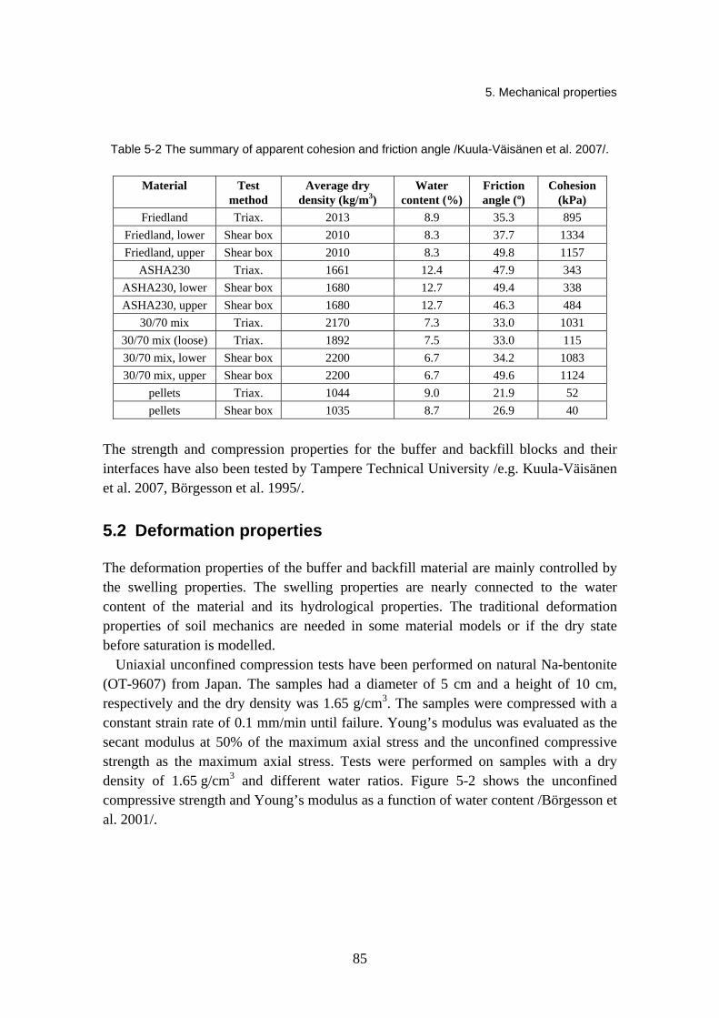
5. Mechanical properties
85
Table 5-2 The summary of apparent cohesion and friction angle /Kuula-Väisänen et al. 2007/.
Material Test method
Average dry density (kg/m3)
Water content (%)
Friction angle (º)
Cohesion (kPa)
Friedland Triax. 2013 8.9 35.3 895 Friedland, lower Shear box 2010 8.3 37.7 1334 Friedland, upper Shear box 2010 8.3 49.8 1157
ASHA230 Triax. 1661 12.4 47.9 343 ASHA230, lower Shear box 1680 12.7 49.4 338 ASHA230, upper Shear box 1680 12.7 46.3 484
30/70 mix Triax. 2170 7.3 33.0 1031 30/70 mix (loose) Triax. 1892 7.5 33.0 115 30/70 mix, lower Shear box 2200 6.7 34.2 1083 30/70 mix, upper Shear box 2200 6.7 49.6 1124
pellets Triax. 1044 9.0 21.9 52 pellets Shear box 1035 8.7 26.9 40
The strength and compression properties for the buffer and backfill blocks and their interfaces have also been tested by Tampere Technical University /e.g. Kuula-Väisänen et al. 2007, Börgesson et al. 1995/.
5.2 Deformation properties
The deformation properties of the buffer and backfill material are mainly controlled by the swelling properties. The swelling properties are nearly connected to the water content of the material and its hydrological properties. The traditional deformation properties of soil mechanics are needed in some material models or if the dry state before saturation is modelled.
Uniaxial unconfined compression tests have been performed on natural Na-bentonite (OT-9607) from Japan. The samples had a diameter of 5 cm and a height of 10 cm, respectively and the dry density was 1.65 g/cm3. The samples were compressed with a constant strain rate of 0.1 mm/min until failure. Young’s modulus was evaluated as the secant modulus at 50% of the maximum axial stress and the unconfined compressive strength as the maximum axial stress. Tests were performed on samples with a dry density of 1.65 g/cm3 and different water ratios. Figure 5-2 shows the unconfined compressive strength and Young’s modulus as a function of water content /Börgesson et al. 2001/.
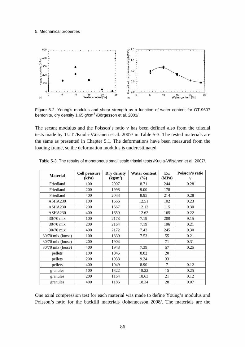
5. Mechanical properties
86
Figure 5-2. Young’s modulus and shear strength as a function of water content for OT-9607 bentonite, dry density 1.65 g/cm3 /Börgesson et al. 2001/.
The secant modulus and the Poisson’s ratio ν has been defined also from the triaxial tests made by TUT /Kuula-Väisänen et al. 2007/ in Table 5-3. The tested materials are the same as presented in Chapter 5.1. The deformations have been measured from the loading frame, so the deformation modulus is underestimated.
Table 5-3. The results of monotonous small scale triaxial tests /Kuula-Väisänen et al. 2007/.
Material Cell pressure (kPa)
Dry density (kg/m3)
Water content (%)
E50 (MPa)
Poisson’s ratioν
Friedland 100 2007 8.71 244 0.28 Friedland 200 1998 9.00 178 Friedland 400 2033 8.95 214 0.28 ASHA230 100 1666 12.51 102 0.23 ASHA230 200 1667 12.12 115 0.30 ASHA230 400 1650 12.62 165 0.22 30/70 mix 100 2173 7.19 200 9.15 30/70 mix 200 2164 7.19 196 0.21 30/70 mix 400 2172 7.42 245 0.30
30/70 mix (loose) 100 1830 7.53 55 0.21 30/70 mix (loose) 200 1904 71 0.31 30/70 mix (loose) 400 1943 7.39 57 0.25
pellets 100 1045 8.82 20 pellets 200 1038 9.24 33 pellets 400 1049 8.90 7 0.12
granules 100 1322 18.22 15 0.25 granules 200 1164 18.63 21 0.12 granules 400 1186 18.34 28 0.07
One axial compression test for each material was made to define Young’s modulus and Poisson’s ratio for the backfill materials /Johannesson 2008/. The materials are the

5. Mechanical properties
87
same, which have been tested in Tampere University of Technology. The test results are presented in Table 5-4.
Table 5-4. Evaluated Young’s modulus and Poisson ratio from one axial compression tests /Johannesson 2008/.
Test Mtrl Dry density Water ratio E-modulus ν No (kg/m3) (MPa) 2 Friedland 2047 0,094 264 0.27 3 Friedland 2058 0,091 297 0.22 4 Friedland 2064 0,089 256 0.24 5 30/70 mix 2175 0,060 177 0.24 6 30/70 mix 2173 0,059 212 0.19 7 30/70 mix 2171 0,063 265 0.11 8 Asha 230 B 1679 0,171 244 0.11 9 Asha 230 B 1692 0,168 265 0.13
10 Asha 230 B 1693 0,174 250 0.09 11 Asha 230 B 1684 0,172 244 0.08 12 Asha 230 B 1689 0,172 248 0.09 13 Asha 230 B 1698 0,173 256 0.09
5.3 Rheological properties (creep)
The rheological properties mean the time dependent strains that will happen in long-term. The rheology of buffer and backfill materials is of importance during and after saturation. In soil mechanics time dependent strain (or deformation) is normally divided into two phases: primary and secondary consolidation /Korkiala 1984/. The primary consolidation (later consolidation) is strain that will happen when the excess pore water pressure, caused by loading, dissipates from the material. The secondary consolidation (usually called as creep) is a strain that will increase with time at a constant load and constant pore water pressure /Börgesson et al. 1995/. In many cases it is assumed that these phases happen successively, but in practice they are overlapping. While the buffer and backfill materials are both compacted into high density, primary consolidation strains can be assumed to be insignificant.
There are some experiments from 1980’s and 1990’s to define the creep properties of the buffer clay. The parameters have been defined from triaxial and oedometer tests /Börgesson et al. 1995/ and from Bench-scale experiments /Pusch & Adey 1999/. The triaxial and oedometer tests have been conducted to the MX-80 buffer material, which density has been varied (for example Figure 5-3).
Like Figure 5-3 (left) shows the creep curve becomes a straight line in double logarithmic diagram. The creep line can be defined by the inclination of the line (n) and

5. Mechanical properties
88
the level of the line as the creep rate dεcd/dt after t = 10 000 sec. /Börgesson et al.1995/. The inclination n is (Equation 5.1)
( )⎟⎠⎞⎜
⎝⎛Δ
Δ=
dtd
tncdε
log (5-1)
where n is inclination of the creep line dεcd/dt creep rate t time εcd deviatoric creep.
The level of the line depends on the magnitude of the deviatoric stress, which can be expressed as the ratio of the applied deviatoric stress and the deviatoric stress at failure Dr (Equation 5.2) /e.g. Börgesson et al. 1995/.
( ) frD
31
31
σσσσ
−−
= (5-2)
where Dr is the degree of mobilised strength (varies between 0 - 1,0) σ1-σ3 applied deviatoric stress q, kPa (σ1-σ3)f deviatoric stress at failure.
The creep test results, when the Dr is smaller than 0.1 are presented in Table 5-5.
Table 5-5. Undrained triaxial creep tests (ρm = density at water saturation, ui = initial pore pressure, σ3 = cell pressure) /Börgesson et al. 1995/.
Test ρm, (t/m3) σ3, kPa ui, kPa σ1-σ3, kPa Dr dεcd/dt
(t = 10 000 sec.) n
1 1.6 1000 425 5.0 0.015 4.5·10-9 0.8 2 1.7 800 487 12.5 0.066 3.3·10-9 0.88
The amount of creep depends greatly on degree of mobilized strength. Figure 5-3 (right) presents the relation between Dr and the creep rate after 10 000 s. The relation is a straight line in the semi-logarithmic diagram for values not too close to Dr = 0 or Dr = 1 /Börgesson et al. 1995/.
The Bench-scale experiments (1:20) were conducted in 1985, but the main results are presented in Pusch & Adey /1999/. The tested material is a smectite rich buffer material, which density in saturation is 2 100 kg/m3. The tests simulate the water saturation phase with a small copper cylinder. The test time and test temperature have been varied. The test results proved that the higher temperature may increase the creep rate somewhat. The normally applied creep equations, like Singh & Mitchell /1968/, give so conservative

5. Mechanical properties
89
results, that according to Pusch & Adey /1999/ the results include the potential increase of the creep rate caused by the higher temperatures.
Figure 5-3. Left: Example of creep test on MX-80 bentonite as a function of time with the ρm = 1.99t/m3, σ3 = 4.84 MPa and Dr = 0.4; Right: Creep rate after 10 000 seconds of MX-80 bentonite as a function of mobilied strength Dr in triaxial test /Börgesson et al. 1995/.
The creep tests conducted by Börgesson et al. /1995/ have been relatively short (around 12 days). Pusch & Adey have presented longer tests with the maximum time of 225 days. According to the preliminary studies by Börgesson & Hernelind /2006/ and Pusch & Adey /1999/ the creep of the canister into the buffer below it (sinking) is insignificant.
Börgesson et al. /1995/ has also reported the influence of the loading rate to some properties. The influence is especially important in the rock shear case, when the displacement of the rock can be very fast if it emanates from an earthquake or very slow if it stems from rock creep. The rate of strain is related to the creep phenomena, but it is only important for deviatoric strain. The influence is thus primarily interesting for the shear strength and can be investigated by performing undrained shear tests for MX-80 bentonite /Börgesson et al. 1988/. Figure 5-4 illustrates three undrained shear tests performed with different rate of strains. The shear strength increases with increasing shear rate according to Equation 5.3.
n
ofof ⎥
⎦
⎤⎢⎣
⎡=
γγττ
(5-3)
where τf is shear strength, kPa, τfo shear strength at the reference rate of shear strain n rate factor γ rate of shear strain (1/s)
oγ reference rate of shear strain (1/s).

5. Mechanical properties
90
According to the investigations of Börgesson et al. /1988/ the rate dependency factor n is about 0.065. This means that the shear strength will increase by 16% at an increase in rate by 10 times.
Figure 5-4. The shear strength at different strain rates measured in three shear tests on samples of MX-80 bentonite with different void ratios /Börgesson et al. 1995/.
5.4 Swelling properties
The swelling properties have been studied in many research projects. The swelling properties are nearly connected to the hydraulic properties of the materials. Usually swelling pressure and hydraulic conductivity are measures in a so called swelling pressure oedometer /Börgesson et al. 1995/. The height of the compacted sample was 20 mm and diameter 50 mm. The samples were heated and cooled in several steps. In general the swelling pressure varied only somewhat (increased or decreased) when the temperature was raised. But the hydraulic conductivity increased up to 5–8 times bigger when the temperature was raised from room temperature to +120 °C. The tested materials included Na-montmorillonite and industrially converted Ca-montmorillonite. The changes caused by the temperature changes were smaller for the dense samples /Börgesson et al. 1995/.
Clay Technology AB have developed a swelling/compression test to measure swelling pressure at constant volume /Börgesson et al. 1995/. In the swelling/compression test it is possible to measure both axial and radial swelling pressure. Na-bentonite MX-80 and Ca-bentonite Moosburg have been tested with distilled water and one test was run with 3.5% NaCl in the pore water. Figure 5-5 presents results of the three swelling/compression tests (ei = initial void ratio). The test results show that the changes in the radial swelling pressure are smaller than in the axial pressure during stepwise unloading-reloading cycle. With smaller swelling pressures radial pressure has been higher than axial pressure.

5. Mechanical properties
91
Figure 5-5. Swelling/compression tests. Top: Na-bentonite MX-80 with distilled water (ei = 0.66); Middle: Moosburg Ca-bentonite with distilled water (ei = 0.63); Bottom: Na-bentonite MX-80 heated up to +90 °C (ei = 0.65) /Börgesson et al. 1995/.
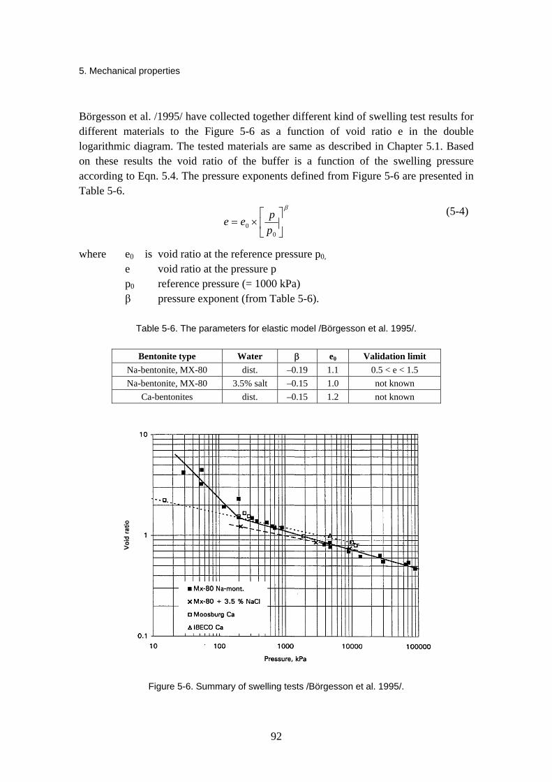
5. Mechanical properties
92
Börgesson et al. /1995/ have collected together different kind of swelling test results for different materials to the Figure 5-6 as a function of void ratio e in the double logarithmic diagram. The tested materials are same as described in Chapter 5.1. Based on these results the void ratio of the buffer is a function of the swelling pressure according to Eqn. 5.4. The pressure exponents defined from Figure 5-6 are presented in Table 5-6.
β
⎥⎦
⎤⎢⎣
⎡×=
00 p
pee (5-4)
where e0 is void ratio at the reference pressure p0,
e void ratio at the pressure p p0 reference pressure (= 1000 kPa) β pressure exponent (from Table 5-6).
Table 5-6. The parameters for elastic model /Börgesson et al. 1995/.
Bentonite type Water β e0 Validation limit Na-bentonite, MX-80 dist. –0.19 1.1 0.5 < e < 1.5 Na-bentonite, MX-80 3.5% salt –0.15 1.0 not known
Ca-bentonites dist. –0.15 1.2 not known
Figure 5-6. Summary of swelling tests /Börgesson et al. 1995/.

5. Mechanical properties
93
Cho et al. /2000/ has conducted swelling pressure tests with calcium bentonite from Kyungju, Kyungsangbuk-do, Korea. The objective of the tests was to evaluate the temperature effects on swelling and hydraulic properties and to measure the time effects of swelling. The Figure 5-7 and Figure 5-8 illustrate the results. Figure 5-7 shows that the horizontal swelling pressure is smaller than the vertical but the difference is smaller when the bentonite is looser. The results demonstrated that the hydraulic conductivity and the swelling pressure of compacted bentonite increased with increasing temperature, but the effect of temperature elevation is not large.
Figure 5-7. The progress of the swelling pressure with time at +20 °C with different dry densities /Cho et al. 2000/.
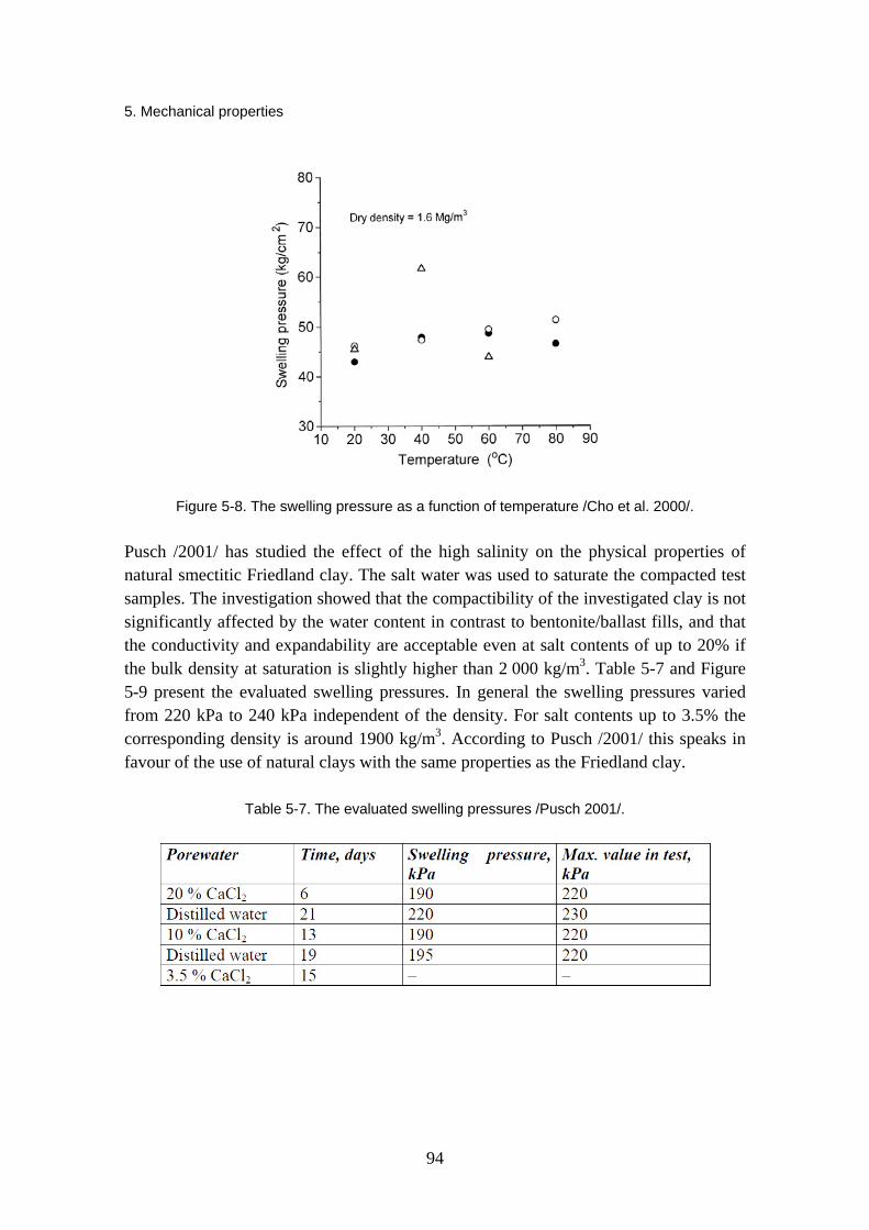
5. Mechanical properties
94
Figure 5-8. The swelling pressure as a function of temperature /Cho et al. 2000/.
Pusch /2001/ has studied the effect of the high salinity on the physical properties of natural smectitic Friedland clay. The salt water was used to saturate the compacted test samples. The investigation showed that the compactibility of the investigated clay is not significantly affected by the water content in contrast to bentonite/ballast fills, and that the conductivity and expandability are acceptable even at salt contents of up to 20% if the bulk density at saturation is slightly higher than 2 000 kg/m3. Table 5-7 and Figure 5-9 present the evaluated swelling pressures. In general the swelling pressures varied from 220 kPa to 240 kPa independent of the density. For salt contents up to 3.5% the corresponding density is around 1900 kg/m3. According to Pusch /2001/ this speaks in favour of the use of natural clays with the same properties as the Friedland clay.
Table 5-7. The evaluated swelling pressures /Pusch 2001/.

5. Mechanical properties
95
Figure 5-9. The swelling pressure as a function of density with different salt liquids /Pusch 2001/.
Villar & Lloret /2004/ have studied the influence of temperature on the hydro-mechanical behaviour of the compacted Febex bentonite. The swelling strains of bentonite upon saturation are a function of temperature and vertical stress: at high temperatures, the swelling capacity of clay decreases, although the influence of temperature is less evident when the vertical stress is high. Likewise, a decrease in swelling pressure as a function of temperature (down to 2.5 MPa at 80 °C) was observed (Figure 5-10).
Figure 5-10. Swelling pressure as a function of temperature for the saturated clay average dry density 1.58 g/cm3 /Villar & Lloret 2004/.

5. Mechanical properties
96
Komine has presented a simplified evaluation for swelling characteristics of bentonites /2004a/ and hydraulic conductivities of sand-bentonite mixtures /2004b/. He has presented concepts of the swelling processes of bentonite-sand mixtures at constant volume and at constant vertical pressure (Figure 5-11).
Figure 5-11. Concept of processes of the swelling behaviour of bentonite sand mixture at a constant volume and constant vertical pressure /Komine 2004b/.
Komine /2004a/ has studied the differences between four bentonites to be used as a buffer material. The study included the laboratory tests on the swelling pressure and swelling deformation of four kinds of bentonite produced in Japan and the United States

5. Mechanical properties
97
from the viewpoint of the physicochemical properties of each bentonite. Furthermore, the study also proposed the simplified evaluation of swelling characteristics of various bentonites on the basis of microscopic analysis. The swelling-pressure and swelling-deformation test apparatuses were developed for this study. The Table 5-8 presents the profiles for the studied materials and Figure 5-12 the relationship between initial dry and maximum swelling pressure.
Table 5-8. The material profiles /Komine 2004a/.
Figure 5-12. Relationship between initial dry density and maximum swelling pressure /Komine 2004a/.

5. Mechanical properties
98
Figure 5-13. Relationship between vertical pressure σv and swelling volumetric strain ε∗sv /Komine 2004a/.
Komine /2004a/ (in Figure 5-13) drew following conclusions from this experimental study:
1. The maximum swelling pressure of calcium type Bentonites C and D is larger than that of the sodium-type Bentonites A and B, when the initial dry density is the same. The montmorillonite contents of C and D are larger than the others. Therefore, it is considered that the large maximum swelling pressures of C and D are caused by the high montmorillonite contents. From the above considerations, it is found that the maximum swelling pressure is strongly influenced by the montmorillonite content rather than the exchangeable-cation composition in bentonite.
2. The swelling-deformation test results indicate that the maximum swelling strain of calcium-type bentonite C is markedly less than the others. The maximum swelling strains of Bentonites A, B and D on condition that the vertical pressure is relatively small are almost the same at the same initial dry density despite that the montmorillonite contents of A, B and D are quite different. Therefore, it is found that the maximum swelling strain is strongly influenced by the exchangeable-cation composition in bentonite rather than the montmorillonite content. Sodium-type bentonite has larger maximum swelling strain than calcium-type one.
Komine /2004b/ studied also sand-bentonite mixtures for use as backfill materials. The hydraulic properties of sand-bentonite mixtures were studied experimentally as a function of dry density and bentonite content. The study proposed simplified evaluation for

5. Mechanical properties
99
hydraulic conductivity using a parameter proposed by the author: swelling volumetric strain of montmorillonite. The evaluation method can obtain hydraulic conductivity of backfill materials at various dry densities and bentonite contents. The study used commercial bentonite, Kunigel-V1 (montmorillonite content 48%) and Mikawa silicate sand no. 6. Sand particle density was 2.66 Mg/m3 and particle diameter was 0.053–0.590 mm. For backfill materials, this study used mixtures with bentonite contents of 5%, 10%, 20%, 30% and 50%. The Figure 5-14a and 5-14b present the test results. Komine /2004b/ could address a simple relationship between hydraulic conductivity and bentonite content from the viewpoint of bentonite swelling in backfill voids (5-14b).
Figure 5-14a. Relationship between bentonite content and permeabilty /Komine 2004b/.
Figure 5–14b. Relationship between permeability and swelling volumetric strain ε∗sv /Komine 2004b/.

5. Mechanical properties
100
Villar et al./2005/ have studied the effect of thermo-hydraulic treatment to the FEBEX bentonite in a small scale laboratory tests. Six sample blocks were uniaxially compacted at a dry density of 1.65 g/cm3. The bottom surface of the material was heated at 100 °C and the top surface was injected with granitic water. The duration of the tests was 6, 12 and 24 months. The temperatures inside the clay and the water intake were measured during the tests and, at the end, the cells were dismounted and the dry density, water content and some hydro-mechanical properties of the clay (permeability, swelling pressure and swelling under load) were measured at different positions. The values obtained were compared to those of the untreated FEBEX bentonite. The injection of cold water provoked in the vicinity of the hydration surface (600 mm) an increase of the water content and a decrease of the dry density due to the swelling of the clay, while heating gives rise to an increase of the dry density and a reduction of the water content in the 180 mm closest to the heater, even after 2 years of thermo-hydraulic (TH) treatment. The swelling capacity and the hydraulic conductivity after TH treatment were mainly related to the dry density and water content attained during it (Figure 5-15). Villar et al. /2005/ concluded that possible hydro-mechanical modifications seemed to be quite reversible, as the values obtained in the saturated sample after TH treatment were in the order of those expected for the untreated clay.
Figure 5-15. Swelling pressure of FEBEX bentonite subjected to TM treatment during different periods of time as a function of the distance to the heater (dry densities of the specimens in g/cm3) /Villar et al. 2005/.
Karnland et al. /2006/ have studied mineralogy and sealing properties of 15 various bentonites and smectite-rich clays. The materials from India, Greece and the US were high-quality bentonites from active mines, representing a significant part of the present global production. The present Czech, Danish and German materials are generally of
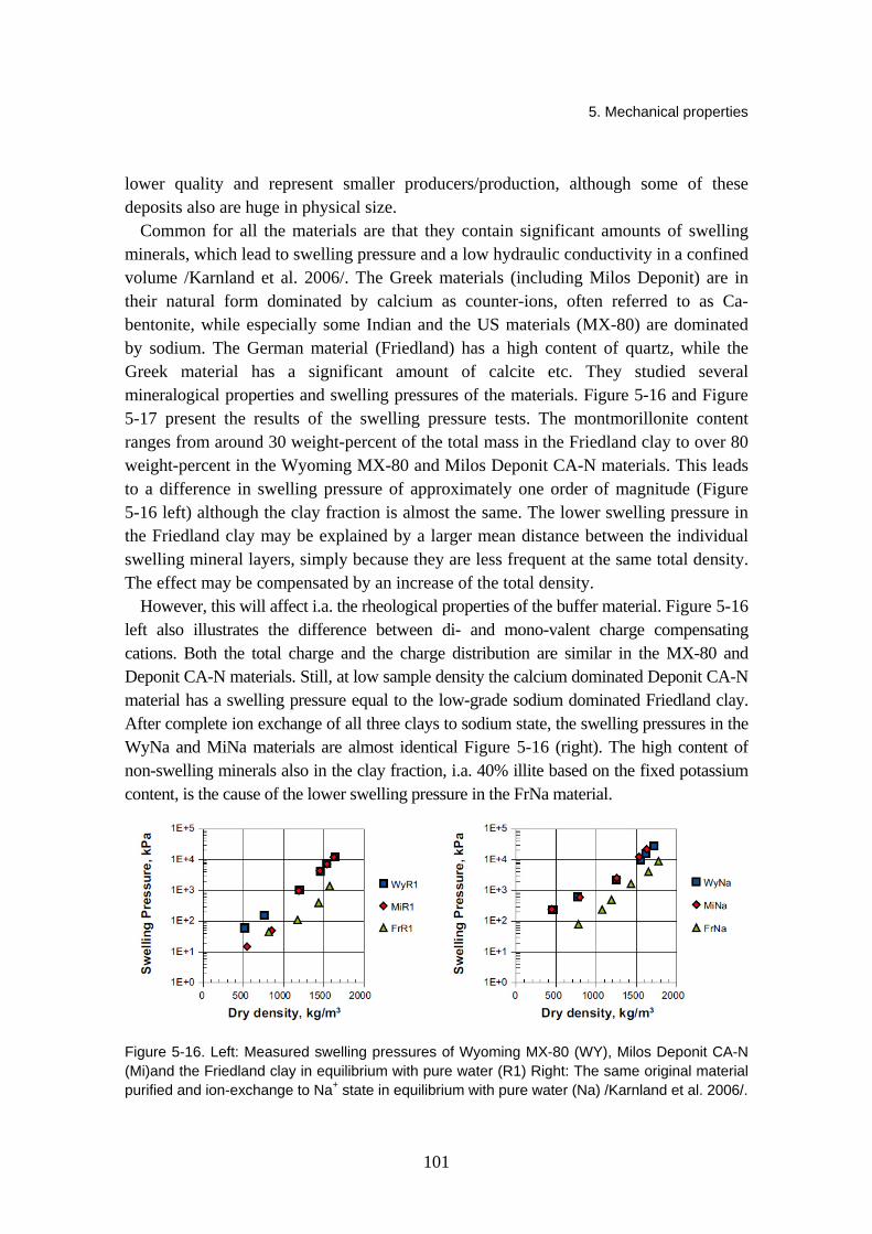
5. Mechanical properties
101
lower quality and represent smaller producers/production, although some of these deposits also are huge in physical size.
Common for all the materials are that they contain significant amounts of swelling minerals, which lead to swelling pressure and a low hydraulic conductivity in a confined volume /Karnland et al. 2006/. The Greek materials (including Milos Deponit) are in their natural form dominated by calcium as counter-ions, often referred to as Ca-bentonite, while especially some Indian and the US materials (MX-80) are dominated by sodium. The German material (Friedland) has a high content of quartz, while the Greek material has a significant amount of calcite etc. They studied several mineralogical properties and swelling pressures of the materials. Figure 5-16 and Figure 5-17 present the results of the swelling pressure tests. The montmorillonite content ranges from around 30 weight-percent of the total mass in the Friedland clay to over 80 weight-percent in the Wyoming MX-80 and Milos Deponit CA-N materials. This leads to a difference in swelling pressure of approximately one order of magnitude (Figure 5-16 left) although the clay fraction is almost the same. The lower swelling pressure in the Friedland clay may be explained by a larger mean distance between the individual swelling mineral layers, simply because they are less frequent at the same total density. The effect may be compensated by an increase of the total density.
However, this will affect i.a. the rheological properties of the buffer material. Figure 5-16 left also illustrates the difference between di- and mono-valent charge compensating cations. Both the total charge and the charge distribution are similar in the MX-80 and Deponit CA-N materials. Still, at low sample density the calcium dominated Deponit CA-N material has a swelling pressure equal to the low-grade sodium dominated Friedland clay. After complete ion exchange of all three clays to sodium state, the swelling pressures in the WyNa and MiNa materials are almost identical Figure 5-16 (right). The high content of non-swelling minerals also in the clay fraction, i.a. 40% illite based on the fixed potassium content, is the cause of the lower swelling pressure in the FrNa material.
Figure 5-16. Left: Measured swelling pressures of Wyoming MX-80 (WY), Milos Deponit CA-N (Mi)and the Friedland clay in equilibrium with pure water (R1) Right: The same original material purified and ion-exchange to Na+ state in equilibrium with pure water (Na) /Karnland et al. 2006/.
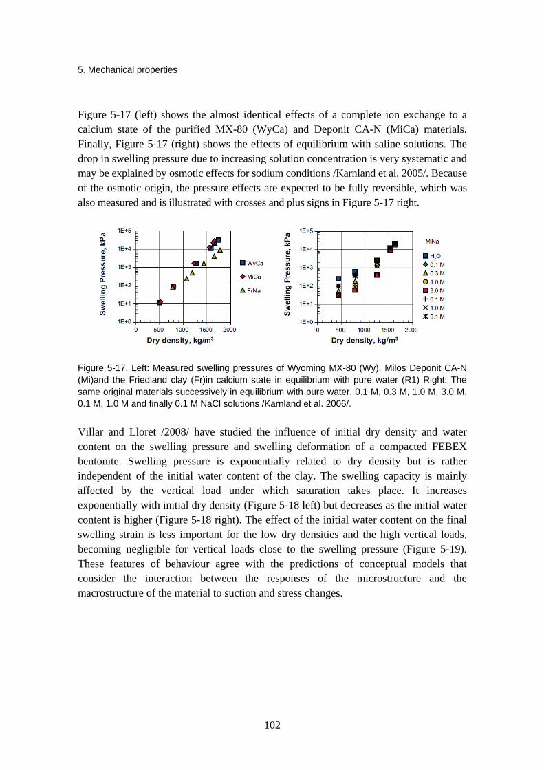
5. Mechanical properties
102
Figure 5-17 (left) shows the almost identical effects of a complete ion exchange to a calcium state of the purified MX-80 (WyCa) and Deponit CA-N (MiCa) materials. Finally, Figure 5-17 (right) shows the effects of equilibrium with saline solutions. The drop in swelling pressure due to increasing solution concentration is very systematic and may be explained by osmotic effects for sodium conditions /Karnland et al. 2005/. Because of the osmotic origin, the pressure effects are expected to be fully reversible, which was also measured and is illustrated with crosses and plus signs in Figure 5-17 right.
Figure 5-17. Left: Measured swelling pressures of Wyoming MX-80 (Wy), Milos Deponit CA-N (Mi)and the Friedland clay (Fr)in calcium state in equilibrium with pure water (R1) Right: The same original materials successively in equilibrium with pure water, 0.1 M, 0.3 M, 1.0 M, 3.0 M, 0.1 M, 1.0 M and finally 0.1 M NaCl solutions /Karnland et al. 2006/.
Villar and Lloret /2008/ have studied the influence of initial dry density and water content on the swelling pressure and swelling deformation of a compacted FEBEX bentonite. Swelling pressure is exponentially related to dry density but is rather independent of the initial water content of the clay. The swelling capacity is mainly affected by the vertical load under which saturation takes place. It increases exponentially with initial dry density (Figure 5-18 left) but decreases as the initial water content is higher (Figure 5-18 right). The effect of the initial water content on the final swelling strain is less important for the low dry densities and the high vertical loads, becoming negligible for vertical loads close to the swelling pressure (Figure 5-19). These features of behaviour agree with the predictions of conceptual models that consider the interaction between the responses of the microstructure and the macrostructure of the material to suction and stress changes.

5. Mechanical properties
103
Figure 5-18. Left: Swelling pressure versus dry density of the FEBEX-bentonite at the end of the test, saturated with deionised water, and exponential fit. The initial water content of the samples was hygroscopic (13.2 ± 1.2%; Right: Influence of initial water content on the swelling pressure, dry densities in Mg/m3 /Villar & Lloret 2008/.
Figure 5-19. Left: Evolution of vertical strain under different vertical pressures (initial dry density 1.6 Mg/m3); Right: Final strain reached in swelling-deformation tests performed with samples of initial dry density Mg/m3 /Villar & Lloret 2008/.
Expansive clay buffers in radioactive waste disposal designs experience cyclic drying and wetting paths during different stages of their design life /Alonso et al. 2005/. Clayey soils subjected to these processes develop swelling and shrinkage deformations, which give rise to the accumulation of compression or expansion strains during suction cycles. Experimental studies were undertaken using oedometer tests on an artificially prepared bentonite-sand mixture (80% FEBEX-bentonite by dry mass). The mixture was statically compacted to a dry density of 1.5 Mg/m3 and a degree of saturation close to 0.35. In order to study these processes and to identify the most important features controlling soil behaviour, several wetting–drying cycles with suctions ranging between 130 and 4 MPa were applied using vapour equilibrium technique and covering a wide

5. Mechanical properties
104
range of overconsolidation ratios (OCR). Suction cycles were applied by means of vapour equilibrium technique in an oedometer cell. The vertical confining stress was kept constant during each series of suction reversals. The initial overconsolidation ratio (OCR), taking as a reference the saturated preconsolidation stress (estimated from the swelling pressure), varied between 1.6 and 7. It was observed that samples experienced a progressive shrinkage as the suction cycles accumulate (Figure 5-20). Eventually a reversible elastic response was approached. This progressive shrinkage process led to an increase of the OCR.
Figure 5-20. Volumetric deformations in cyclic controlled-suction paths, Left, σv = 196 kPa, right σv = 396 kPa /Alonso et al. 2005/.
In the dismantling of the five years old FEBEX in situ experiment Villar and Lloret /2007/ found that the water retention capacity, the hydraulic conductivity and the swelling capacity of the samples from Grimsel have not irreversibly changed after operation. Accordingly, the thermal conductivity is higher for the bentonite blocks of the external ring of the barrier, whereas their swelling capacity is lower. The preconsolidation pressure of the Grimsel samples has decreased due to the microstructural changes associated to the volume increase experienced during hydration and to the swelling stress applied. This expansion of the bentonite has caused the filling of all the construction gaps of the barrier.
The dry density and water content gradients observed in the barrier had a repercussion on its thermo-hydromechanical properties, since most of them depended greatly on the density and water content of the bentonite. This lead to an inhomogeneous distribution of swelling pressures, permeability and water retention among others, that should be taken into account in modelling exercises. With the data available Villar and Lloret /2007/ could not determine if the density gradients observed in the bentonite barrier
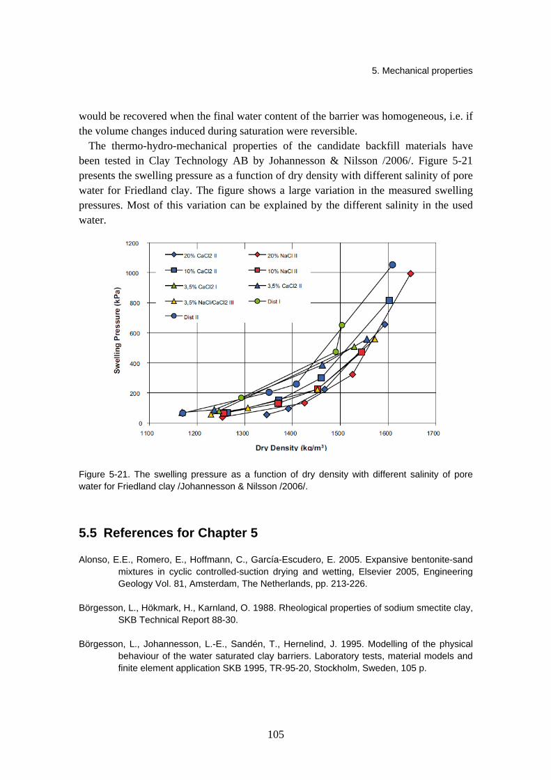
5. Mechanical properties
105
would be recovered when the final water content of the barrier was homogeneous, i.e. if the volume changes induced during saturation were reversible.
The thermo-hydro-mechanical properties of the candidate backfill materials have been tested in Clay Technology AB by Johannesson & Nilsson /2006/. Figure 5-21 presents the swelling pressure as a function of dry density with different salinity of pore water for Friedland clay. The figure shows a large variation in the measured swelling pressures. Most of this variation can be explained by the different salinity in the used water.
Figure 5-21. The swelling pressure as a function of dry density with different salinity of pore water for Friedland clay /Johannesson & Nilsson /2006/.
5.5 References for Chapter 5
Alonso, E.E., Romero, E., Hoffmann, C., García-Escudero, E. 2005. Expansive bentonite-sand mixtures in cyclic controlled-suction drying and wetting, Elsevier 2005, Engineering Geology Vol. 81, Amsterdam, The Netherlands, pp. 213-226.
Börgesson, L., Hökmark, H., Karnland, O. 1988. Rheological properties of sodium smectite clay, SKB Technical Report 88-30.
Börgesson, L., Johannesson, L.-E., Sandén, T., Hernelind, J. 1995. Modelling of the physical behaviour of the water saturated clay barriers. Laboratory tests, material models and finite element application SKB 1995, TR-95-20, Stockholm, Sweden, 105 p.

5. Mechanical properties
106
Börgesson, L., Karnland, O., Johannesson, L.-E. 1996. Modelling of the physical behaviour of clay barriers close to water saturation, Elsevier, 1996, Engineering Geology, 41, Amsterdam, The Netherlands, pp. 127–144.
Börgesson, L., Chijimatsu, M., Fujita, T., Nguyen, T.S., Rutqvist, J., Jing, L. 2001. Thermo-hydro-mechanical characterisation of a bentonite-based buffer material by laboratory tests and numerical back analyses, Elsevier, International Journal of Rock Mechanics and Mining Sciences Vol. 38, Amsterdam, The Netherlands, pp. 95–104.
Börgesson, L., Hernelind, J. 2006. Water saturation phase of the buffer and backfill in the KBS-3V concept, SKB 2006, TR-06-14, Stockholm, Sweden, 97 p.
Carlson, L. 2004. Bentonite mineralogy, Part 1: Methods of investigation – a literature review, Part 2: Mineralogical research of selected bentonites. Posiva Oy, Olkiluoto. Working report 2004-02.
Cho, W.-J., Lee, J.-O., Kang, C.-H. 2000. Influence of temperature elevation on the sealing performance of a potential buffer material for a high-level radioactive waste repository, Annals of Nuclear Energy, 27, Elsevier, Amsterdam, The Netherlands, pp. 1271–1284.
Johannesson, L.E., Nilsson, U. 2006. Deep repository – engineered barrier systems. Geotechnical behaviour of candidate backfill materials. Laboratory tests and calculations for determining performance of the backfill. SKB R-06-73, Svensk Kärnbränslehantering AB.
Johannesson, L.E. 2008. Backfilling and closure of the deep repository – Phase 3 pilot test to verify engineering feasibility, Geotechnical investigations made on unsaturated backfill materials, SKB, Stockholm, Sweden, R-08-131, 27 p.
Karnland, O., Olsson, S., Nilsson, U. 2006. Mineralogy and sealing properties of various bentonites and smectite-rich clay materials, SKB 2006, TR-06-30, Stockholm, Sweden, 70 p.
Komine, H. 2004a. Simplified evaluation for swelling characteristics of bentonites, Elsevier, Engineering Geology Vol. 71, Amsterdam, The Netherlands, pp. 265–279.
Komine, H. 2004b. Simplified evaluation on hydraulic conductivities of sand-bentonite mixture backfill, Elsevier, Applied Clay Science Vol. 26, Amsterdam, The Netherlands, pp. 13–19.
Korkiala, L. 1984. The rate of the Settlement of the Consolidating and Creeping Soil Layer, Helsinki University of Technology Master Thesis, Espoo, 87 p.
Kuula-Väisänen, P., Kolisoja, P. 2007. Backfilling and closure of deep repository. Phase 3 pilot test to assess feasibility. Subproject 1; Laboratory tests to understand processes during installation and saturation, Tampere University of Technology, TUT report 1, Tampere, Finland, 53 p.
Pusch, R. 1998. Backfilling with mixtures of bentonite/ballast materials or natural smectitic clay? Swedish Nuclear Fuel and Waste Management Co (SKB), Stockholm. Technical Report TR-98-16, 52 p.
5. Mechanical properties
107
Pusch, R., Adey, R. 1999. Creep in buffer clay, SKB, TR-99-32, Stockholm, Sweden, 53 p.
Pusch, R. 2001. Experimental study of the effect of high porewater salinity on the physical properties of a natural smectitic clay, SKB 2001, TR-01-07, Stockholm, Sweden, 35 p.
Singh, A., Mitchell, J.K. 1968. General stress-strain-time function for soils. American Society of Civil Engineers, Proceedings, Vol. 94, No SM1.
Villar, V.M., Lloret, A. 2004. Influence of temperature on the hydro-mechanical behaviour of a compacted bentonite, Elsevier, Applied Clay Science Vol. 26, Amsterdam, The Netherlands, pp. 337–350.
Villar, V.M., Martín, P.L., Bárcala, J.M. 2005. Modification of physical, mechanical and hydraulic properties of bentonite by thermo-hydraulic gradients, Elsevier 2005, Engineering Geology Vol. 81, Amsterdam, The Netherlands, pp. 284–297.
Villar, M.V., Lloret, A. 2007. Dismantling of the first section of the FEBEX in situ test: THM laboratory tests on the bentonite blocks retrieved, Elsevier 2007, Physics and Chemistry of the Earth Vol. 32, Amsterdam, The Netherlands, pp. 716–729.
Villar, M.V., Lloret, A. 2008. Influence of dry density and water content on the swelling of a compacted bentonite. Applied Clay Science Vol. 39, Amsterdam, The Netherlands, pp. 38–49.

6. Summary and evaluation
108
6. Summary and evaluation
The objective of this report was to compile and present state-of-the-art experimental knowledge on bentonite materials planned for use in nuclear waste repositories. Some research data on other relevant backfilling materials was also included. This section of the report provides a summary of the material properties covered in the previous chapters. More evaluation data and conclusions regarding the Bentomap database can be found in Appendix A and Appendix B.
The purpose of the buffer according to the current design /Posiva 2006/ is to maintain the integrity of the canisters for at least 100 000 years by protecting them from detrimental THMBC processes and to limit and retard the release of any radionuclides from the canisters, should any be damaged. The purpose of the backfill is to prevent the formation of water-conductive flow paths, contribute to keeping the tunnels mechanically stable and prevent inadvertent human intrusion to the repository.
Thus, the general requirements defined by Posiva /2006/ for the buffer are a low hydraulic conductivity (≤ 10-12 m/s), adequate density, sufficient swelling pressure and thermal conductivity, as well as chemical buffering capacity. For the backfill, the requirements are the hydraulic conductivity < 10-10
m/s, sufficient swelling pressure and compression modulus, suitable density at complete saturation and consideration of the chemical interaction with other EBS components.
The important attributes of bentonite are that it is chemically and mechanically stable /Posiva 2006/, lends itself to plastic deformations, opposes the circulation of water, is permeable to gases, and has a high retardation capacity and swelling pressure. Some other clays planned for use as backfill also have similar attributes. The bentonite properties depend on the amount of smectite minerals in the bulk material, smectite species and on the exchangeable cations in the interlayer position. Commercial bentonites normally contain 70–90 % smectites. Common accessory minerals are feldspars, quartz, cristobalite, gypsum, calcite and pyrite. Some common bentonites are MX-80, FEBEX, Deponit CA-N and Asha. The swelling backfill clays include Friedland and DPJ.
6. Summary and evaluation
109
All members of the smectite group have a specific 2:1 layer structure. Some of the central cations in the structure have been substituted by cations of lesser charge. The substitutions cause a net negative charge of the montmorillonite layer, which is counterbalanced by cations located in the interlayer space between the individual mineral layers. The type of the charge compensating cation is very relevant in swelling.
6.1 Thermal properties
The thermal conductivity of bentonite seemed to decrease with the increase of void ratio and increase with increasing dry density, degree of saturation, water content and air volume fraction. The influence of mineral composition on thermal conductivity was also observed, while temperature and effective stress had only a rather small effect. Values for the reference material MX-80 bentonite were generally found to be in the range 0.4–1.3 W/m·K, where the lower value is for a low degree of saturation and the higher for the saturated conductivity. For bentonite/ballast mixtures, thermal conductivity was considerably higher.
For specific heat, Eqn. (3-4) was determined to give values between 800–2 500 Ws/kg·K for MX-80 as a function of the water ratio. The influence of temperature on specific heat appeared to be insignificant.
The thermal expansion coefficient for compacted bentonite decreased with increasing dry density in the temperature range 20 to 60 ºC, but no significant difference was observed. The range in values was between 2.2×10⁻⁴ and 3.1×10⁻⁴, the higher value corresponding to lower dry density. Therefore the coefficient of thermal expansion could be assumed to be constant for the buffer material in the repository.
6.2 Hydraulic properties
Hydraulic conductivity was considered to be a function of the composition of the buffer and backfill, void ratio, swelling pressure, groundwater salinity and temperature. The conductivity decreased with increasing density and smectite content and increased with higher salinity. The temperature effects were usually small, but the conductivity slightly rose during heating. The hydraulic conductivity measurements performed in samples of FEBEX bentonite retrieved from in situ tests did not show any important variation of this property of the bentonite after being under repository conditions. The values for MX-80 ranged from 3×10-14 to 1×10⁻⁹ m/s, depending on saturated density and salinity of the water. A close relationship in the origin of swelling pressure and hydraulic conductivity was indicated.
The water retention curve was described as a relation between the water content or the degree of saturation and the energy state or potential of the soil water expressed as
6. Summary and evaluation
110
relative humidity or suction. The retention curve was influenced by the water content history, the time given for equilibration, and the strain state. The retention capacity was found to be higher for unconfined samples, and to decrease with heating. Particularly for MX-80 bentonite, hysteresis on heating/cooling cycles was observed. The retention capacity of the FEBEX clay did not change after five years of being exposed to repository conditions.
6.3 Mechanical properties
The friction angle for different types of bentonite was found to vary from 4° to 13° and cohesion between 40 kPa and 120 kPa. The influence of temperature was low and the influence of salt in the pore water was rather high on strength properties.
The deformation properties of the buffer and backfill material, such as Young’s modulus and Poisson’s ratio, were noted to mainly be controlled by the swelling properties, and the swelling properties were found to be nearly connected to the water content of the material and its hydrological properties.
The rheology of buffer and backfill materials was of importance during and after saturation. The amount of creep depended greatly on the degree of mobilized strength, and higher temperature could increase the creep rate somewhat. The creep of the canister into the buffer below it (sinking) seemed to be insignificant. The influence of the strain rate to shear strength was also reported.
The swelling capacity of bentonite materials was found in some studies to be related to dry density, water content and saline solution concentration. For FEBEX bentonite the swelling capacity decreased at high temperatures and was affected by vertical stress, where as for compacted Kyungju calcium bentonite the swelling pressure was observed to increase slightly with temperature rise. The maximum swelling pressure was strongly influenced by the montmorillonite content rather than the exchangeable-cation composition in bentonite, and the maximum swelling strain was strongly influenced by the exchangeable-cation composition in bentonite rather than the montmorillonite content. Sodium-type bentonite had larger maximum swelling strain than calcium-type bentonite, where as for maximum swelling pressure the situation was the opposite. Higher montmorillonite content lead to an increase in swelling pressure, and an increase in saline solution concentration resulted in a systematic drop in swelling pressure. The swelling capacity of FEBEX bentonite samples from the five years old in situ experiment did not irreversibly change after operation.

7. Conclusions and further research needs
111
7. Conclusions and further research needs
Some general and more specific conclusions can be made based on the issues covered by the Bentomap database and/or knowledge presented in this state-of-the-art report. Appendix A provides a more varied list of the issues regarding the database and forms a partial basis for the following conclusions:
• A great deal of the experimental studies have been performed on bentonites such as MX-80 and FEBEX, or on clays and backfill materials such as Friedland clay.
• There are bentonite materials with quite different geological origin, which have the same suitable basic mineralogical characteristics and thereby similar sealing properties.
• Mechanical and hydraulical parameters have generally been more extensively investigated by experimental methods in the articles and reports than thermal parameters. Particularly physical characteristics such as swelling and hydraulic conductivity of bentonites have been the subject of many investigations. While experiments for specific heat for example are scarce, thermal conductivity measurements, however, are still fairly well supplied.
• Hydraulic conductivity measurements have been conducted in recent years particularly for backfill materials and include testing the property as a function of density, salinity and temperature.
• Effects of salinity on some of the important properties of the buffer and backfill materials are well presented mainly for concentrations under 3.5% and for a single type of salt (mixture of sodium and calcium chlorides).
• Effects of temperature and water content on several bentonite properties can be fairly well found in literature.
• Available information on thermally exposed bentonite give support to a temperature criterion for the bentonite buffer of at least 120 °C. It is also important to note that natural analogue data suggests that the bentonite still keeps rather favorable

7. Conclusions and further research needs
112
hydraulic properties when exposed to temperatures of about 150 ºC in spite of substantial illitisation and cementation effects.
• Some investigation methods for retention curves, it is observed, do not influence the results. However, there are studies that suggest that some methods may well influence the obtained data. The estimation of effective parameters, in general, can be sensitive to the detailed performance of the experimental apparatus.
There are some issues that the current knowledge as presented by the database does not cover extensively or that still require further study:
• Long-term properties of bentonites and the effect of time on sealing and and safety functions require much further study.
• The effect of test scale and up-scaling of small scale experiments to full scale is very much still an issue that requires further work.
• Natural analogies could be explored more widely.
• There is still uncertainty regarding the performance of the bentonite submitted to temperatures above 150 °C.
• Piping and erosion and their effect on the performance of the buffer and backfill is not sufficiently covered or investigated. Further material tests on bentonite-ballast mixtures should be conducted, especially healing of piping channels.
• It is recommended that there should be continued work focused on the development and testing of the block placing method for both the buffer and backfill.
• The continued work should be focused on understanding the effect of water inflow during backfill installation and the processes during saturation and homogenisation of the backfill. The evolution of saturation in the buffer also contains issues not sufficiently studied or understood (such as time to reach full swelling pressure), although the database does contain several investigations on the temperature, water content and saturation evolution of the buffer in particular, and also recent research on homogenization and water uptake of the backfill.
• More tests are required in order to explain the influence of ballast material on the hydraulic conductivity and swelling pressure of bentonite-ballast mixtures.
• The effect of groundwater and pore water salinity, especially on the compressibility and erosion of buffer and backfill materials in unsaturated state, should be further investigated also for higher salt concentrations than 3.5% and for different chemical compositions of salt.
Appendix A: Evaluation of Bentomap database
A1
Appendix A: Evaluation of Bentomap database
Laatija Paula Keto
Tarkastaja Timo Saanio
Hyväksyjä Reijo Riekkola
pvm. 8.2.2008
pvm.
pvm.
Introduction
Bentomap is an electronic database that has been collected with the aim to map and classify bentonite related investigations and their applicability for design work and research concerning the final disposal of nuclear waste in Finland.
This memorandum presents a summary concerning the evaluation of the Bentomap database. The actual evaluation work comprised of adding text to columns evalution of results and applicability of the Bentomap database in Microsoft excel-format. Evaluation of investigations linked to modelling is excluded form this evaluation as well as evaluation of test methods used in different investigations.
Issues covered by the database
The database focuses mostly on investigations concerning thermo-hydro-mechanical characteristics and modelling of bentonite buffer and backfill. However, investigations linked to mineralogical and chemical stability are still at least partially covered by this database.
INSINÖÖRITOIMISTO
SAANIO & RIEKKOLA OY Muistiotunnus
897-1/2008
Appendix A: Evaluation of Bentomap database
The keyword list used in the search from different databases is fairly extensive. However, some terms such as EBS (engineered barrier system) and multi-barrier system were missing from the list. Maybe also some other mineral names from the smectite-group than montmorillonite (beidellite, nontronite etc.) could also have been included in the list.
In general, majority of the investigations listed in this database are considered as relatively short-term laboratory studies. The effect of time with respect to the entire lifetime of the repository is taken better into account in some large-scale field-tests (FEBEX, Prototype repository etc.), in some modelling studies and in three different natural analogy investigations.
The issues covered fairly well by this database include:
- physical characteristics, e.g. swelling and hydraulic conductivity of bentonites (most often MX-80)
- effect of salinity on physical properties of buffer and backfill
- effect of temperature and water content on physical properties of buffer
- smectite-to-illite conversion/alteration/transformation
- thermal properties of bentonite buffer
- characteristics of backfill consisting of in situ compacted mixture of bentonite and ballast
- porewater chemistry (bentonite)
- gas migration in bentonite
- buffer and backfill design.
The issues that are not covered very extensively by the database and/or issues that require further investigations include:
- effect of time on performance of buffer and backfill
- effect of test scale, up-scaling of laboratory-scale results to tunnel/repository-scale
- natural analogies
- long-term effects of radiation on performance of EBS
- performance of block backfill (saturation, homogenisation etc.)
- cement (high pH)–bentonite interaction
- iron–bentonite interaction
- saturation and homogenisation of block backfill
- erosion & piping, especially erosion of bentonite to rock fractures (colloids etc.)
A2

Appendix A: Evaluation of Bentomap database
A3
- self-healing of buffer and backfill materials
- characterisation methods
- microbes
- effect of radiation on performance of buffer/backfill.
There are some central Posiva reports that could be included in the database, e.g. The POSIVA 2006-05 “Expected Evolution of a Spent Nuclear Fuel Repository at Olkiluoto” by Pastina & Hellä (2006). In addition, the Finnish version of process report (Miller & Marcos 2007) could be added to the database.
General conclusions
The Bentomap database covers a wide range of investigations focusing mainly of thermo-hydro-mechanical processes and modelling. The database works also as a tool to identify which areas of investigations are missing from the database or require more work from the scientific community. Clearly, the long lifespan of the HLW repository presents one challenge, i.e. how to scale-up the laboratory test results to repository scale (volume and time). Generally, more natural analogy studies are recommended, although finding a good analogue is always a hard task. In addition, there are some potentially critical processes, such as buffer erosion and chemical interactions that require further investigations and modelling.
References
Pastina, B. & Hellä, P. 2006 (editors). Expected Evolution of a Spent Nuclear Fuel Repository at Olkiluoto. Posiva Oy, Olkiluoto. POSIVA 2006-05.
Miller, B. & Marcos, N. 2007 (editors). Process Report – FEP’s and Scenarios for a spent nuclear fuel repository at Olkiluoto. Posiva Oy, Olkiluoto. POSIVA 2007-12 (in print).


7. Conclusions and further research needs
B1
Appendix B: THM(C) parameters and measurements in BENTOMAP literature list
MEMORANDUM 1(121)
Antti Lempinen 3th of April, 2007
Classification of publications
Modelling bentonite THM(C)-behaviour of bentonite should follow the usual scientific path from observations to hypothesis and back to experimental work. This cycle should be repeated again and again, until the scientific community is so confident on the model that it can be called theory. Currently, there are several models that can describe some of the behaviour of bentonite. None of these can be called theory, since their domain of applicability is too small, and some phenomena cannot be explained by any model.
Significant progress in describing physico-chemical phenomena of bentonite has been made during last 15 years, and understanding of its micro-structure has increased a lot. However, the macroscopic models that are used in computer simulations have not changed much, and most of the effort in developing them has been put on more accurate parameter evaluation.
I have classified reports and articles listed in BENTOMAP reference table. These comments are based on my view of what are the basic requirements of a theory that could explain the observations and could be used for predictions. I have chosen the approach that acceptable model has to be consistent with laws of thermodynamics.
Appendix B: THM(C) parameters and measurements in BENTOMAP literature list
B2
Therefore, the model variables should be derivable from a set of normal thermodynamic variables, with time-scales below observation limit taken into account as restrictions.
Only articles and reports giving primary experimental data are included. The measurements are classified in ten classes according to the set of variables measured. Additionally, type material and controlled variables are listed.
The ten measurement classes are the following:
Shear modulus These are deviatoric straining tests that describe elastic behaviour. Only couple of articles give direct data for this, but failure tests can be also used to determine shear modulus.
Swelling pressure This means pressure caused by increase in moisture content without deformation relative to a reference state. Total swelling pressure means pressure change from the reference state to full saturation. Reference state (load, temperature, humidity) is rarely stated, and constant volume is difficult to maintain. In some cases, therefore, accurate expressions need further analysing of results.
Swelling strain This is volumetric strain needed to keep total pressure constant when moisture content is changed relative to a reference state. There is a number of these measurements, but only a couple publications give separation of irreversible and reversible behaviour with cyclic wetting and drying. Swelling strain is measured changing the suction and holding the load constant, often zero.
Confined suction Suction is originally a quantity of capillary materials defined as the difference between pore air pressure and pressure of pore water. More generally, it is scaled difference between chemical potentials of bulk water with plane surface and pore water in the same temperature. Here, confined suction means measurement of water content in material at different suctions without volume change. The resulting function is called suction curve (ambiguous) or confined suction curve. Since bentonite generates swelling pressure during this measurement, it is difficult to hold volume constant and get accurate results at low suctions.
Unconfined suction Suction depends on deformation, and it has to be determined also when volume is allowed to change. Usually, it is measured without external load, and the resulting function is called suction curve (ambiguous), unconfined suction curve or water retention curve.
Appendix B: THM(C) parameters and measurements in BENTOMAP literature list
B3
Plasticity Measurements of plasticity means here that irreversible straining is measured and separated from reversible behaviour. Most of plasticity measurements are related to deviatoric behaviour, and only couple of sets of experiments has been published with separation of reversible and irreversible volumetric swelling behaviour. The former is important only in the case of rock shearing, while the latter is important in analysing the closing of the installation gaps.
Gas flux Gas flux in unsaturated phase of the buffer is very difficult to measure, since its time scale is so much shorter than that of saturation. In the given list of references, there are no such measurements. In the list, there are some experiments on break-through of gas in saturated bentonite. Since both isothermal and temperature driven transport of vapour are important, more experimental evidence is needed to justify ignoring the Darcy movements of gas.
Moisture flux Mass flux of water constitutes of diffusion and convection of vapour, diffusion of adsorbed water and liquid flow. The relative importance of these is not clear. Therefore, the moisture flow is not divided according to the physical phenomenon but according to the potentials in the generalized diffusion equation. These potentials are moisture content, temperature and concentrations of active species. Most of the measurements are performed with saturated material giving saturated hydraulic conductivity, because it is the most important property of the buffer. There are a few unsaturated isothermal experiments, which give moisture flux driven by moisture content gradient, and a few coupled thermohydraulic experiments, which can be used to determine moisture flux driven by temperature gradient. There a practically no experiments that could be used to determine osmotic flow.
Heat flux Calculation of temperature field is generally the easiest part of predicting the THMC behaviour of bentonite buffer. It is evident that heat conduction dominates over convection and latent heat transportation. The different measurements give consistent and confident results.

Appendix B: THM(C) parameters and measurements in BENTOMAP literature list
B4
Diffusion Diffusion is important in long-time performance assessment of the buffer. In re-saturation phase, redistribution of species that affect the properties of bentonite is an issue. Such species are mainly ions affecting hydration of montmorillonite and thus swelling and hydraulic conductivity. So far, there are only couple of publications about unsaturated redistribution of salts and sulfate.
Controlling other variables means, in this context, that the experiments are repeated with different constant values of these variables. Most importantly, controlling temperature is important because there is significant temperature gradient during the re-saturation phase of a repository. In thermo-hydraulic experiments, heating power is not always given, but since the heat flux can be reliably calculated, data on temperature gradient suffices. When the effects of geochemical properties are measured, the controlled variables are concentrations in external solutions.
Most of the publications are about measurements with MX-80 and FEBEX bentonites. There are also some attempts to relate basic THM-properties to mineralogical characteristics, but the microscopic phenomena are not yet well enough known, and up-scaling is a very complicated task because of the complex structure of bentonite.
Conclusions
From the list of publications in Appendix, it is possible to construct a thermodynamical model for THM behaviour of compacted bentonite. Since the microscopic phenomena related to hydration of montmorillonite are not completely understood, there is still, however, a possibility to misinterpretation of experiments. For example, assumptions regarding gaseous fluxes have no direct experimental evidence.
When interactions with other active species are included in the THM model, resulting in THMC model, the experimental data is insufficient. More test results of movements of ions inside unsaturated buffer material is needed, and the dominant phase of water transport is still under debate.

VTT WORKING PAPERS 133VTT CREATES BUSINESS FROM TECHNOLOGY�Technology�and�market�foresight�•�Strategic�research�•�Product�and�service�development�•�IPR�and�licensing�•�Assessments,�testing,�inspection,�certification�•�Technology�and�innovation�management�•�Technology�partnership
•�•�•��VTT�WO
RKIN
G�PA
PERS�133�����B
ENTO
mA
P:�SuR
VEy�Of�B
ENTO
NITE�A
Nd
�TuN
NEl�B
Ac
KfIll�KNO
WlEd
GE
ISBN 978-951-38-7194-9 (URL: http://www.vtt.fi/publications/index.jsp)ISSN 1459-7683 (URL: http://www.vtt.fi/publications/index.jsp)
VTT Working Papers
117 Paula Järvinen, Kai Puolamäki, Pekka Siltanen & Markus Ylikerälä. Visual analytics. Final report. 2009. 45 p. + app. 3 p.
118 Anna-Maija Hietajärvi, Erno Salmela, Ari Happonen & Ville Könönen. Kysyntä- ja toimitusketjun synkronointi metalli- ja konepajateollisuudessa Suomessa. Haastattelututkimus. 2009. 33 s. + liitt. 3 s.
119 Timo Korhonen & Simo Hostikka. Fire Dynamics Simulator with Evacuation: FDS+Evac. Technical Reference and User’s Guide. 2009. 91 p.
120 Veikko Kekkonen & Göran Koreneff. Euroopan yhdentyvät sähkömarkkinat ja markkinahinnan muodostuminen Suomen näkökulmasta. 2009. 80 s.
121 Rinat Abdurafikov. Russian electricity market. Current state and perspectives. 2009. 77 p. + app. 10 p.
122 Bettina Lemström, Juha Kiviluoma, Hannele Holttinen & Lasse Peltonen. Impact of wind power on regional power balance and transfer. 2009. 43 p.
123 Juha Forström. Euroopan kaasunhankinnan malli. 2009. 80 s.124 Jyrki Tervo, Antti Manninen, Risto Ilola & Hannu Hänninen. State-of-the-art of
Thermoelectric Materials Processing, Properties and Applications. 2009. 29 p.125 Salla Lind, Björn Johansson, Johan Stahre, Cecilia Berlin, Åsa Fasth, Juhani Heilala,
Kaj Helin, Sauli Kiviranta, Boris Krassi, Jari Montonen, Hannele Tonteri, Saija Vatanen & Juhani Viitaniemi. SIMTER. A Joint Simulation Tool for Production Development. 2009. 49 p.
126 Mikko Metso. NoTA L_INdown Layer Implementation in FGPA Design results. 2009. 20 p.
127 Marika Lanne & Ville Ojanen. Teollisen palveluliiketoiminnan menestystekijät ja yhteistyösuhteen hallinta - Fleet asset management - hankkeen työraportti 1. 2009. 65 s. + liitt. 12 s.
128 Alternative fuels with heavy-duty engines and vehicles. VTT’s contribution. 2009. 106 p. + app. 8 p.
129 Stephen Fox. Generative production systems for sustainable product greation. 2009. 101 p.
130 Jukka Hemilä, Jyri Pötry & Kai Häkkinen. Tuotannonohjaus ja tietojärjestelmät: kokemuksia sekä kehittämisperiaatteita. 2009. 37 s.
131 Ilkka Hannula. Hydrogen production via thermal gasification of biomass in near-to-medium term. 2009. 41 p.
132 Hannele Holttinen & Anders Stenberg. Tuulivoiman tuotantotilastot. Vuosiraportti 2008. 2009. 49 s. + liitt. 8 s.
133 Elisa Rautioaho & Leena Korkiala-Tanttu. Bentomap: Survey of bentonite and tunnel backfill knowledge – State-of-the-art. 2009. 112 p. + app. 7 p.