technology and use of low power research reactors
TRANSCRIPT
IAEA-TECDOC-384
TECHNOLOGY AND USEOF LOW POWER RESEARCH REACTORS
REPORT OF A CONSULTANTS MEETINGON THE TECHNOLOGY AND USE OF LOW POWER RESEARCH REACTORS
ORGANIZED BY THEINTERNATIONAL ATOMIC ENERGY AGENCY
HELD IN BEIJING, CHINA, 30 APRIL-3 MAY 1985
Et0~ E'A TECHNICAL DOCUMENT ISSUED BY THE.... INTERNATIONAL ATOMIC ENERGY AGENCY, VIENNA, 1986

TECHNOLOGY AND USE OF LOW POWER RESEARCH REACTORSIAEA, VIENNA, 1986IAEA-TECDOC-384
Printed by the IAEA in AustriaAugust 1986

PLEASE BE AWARE THATALL OF THE MISSING PAGES IN THIS DOCUMENT
WERE ORIGINALLY BLANK

The IAEA does not normally maintain stocks of reports in this series.However, microfiche copies of these reports can be obtained from
INIS ClearinghouseInternational Atomic Energy AgencyWagramerstrasse 5P.O. Box 100A-1400 Vienna, Austria
Orders should be accompanied by prepayment of Austrian Schillings 100,-in the form of a cheque or in the form of IAEA microfiche service couponswhich may be ordered separately from the INIS Clearinghouse.
FOREWORD
The research reactor is a versatile tool, useful in a largenumber of scientific disciplines and technologies. Research reactorshave played a significant role in the development of the scientificand technical infrastructure of developed and developing countriesand can assume an important role in the training of manpower tuned tothe requirements for the introduction of nuclear power in a country.
Several developing countries with emerging programmes in nuclearscience and technology are considering purchasing a multipurposeresearch reactor. A reactor in the 1-2 megawatt range is anexpensive undertaking and can cost a minimum of $8-12 million. A lowpower research reactor, power level up to 10kW, may adequately servethe needs of many centres developing a nuclear science and technologyprogramme. The small research reactor has cost advantages, bothcapital and operating, and can still play a significant role in aresearch and training centre.
In order to assist these countries considering the acquisition ofa research reactor, the Agency convened a Consultants' Meeting todevelop information on the technology, operating cost and utilizationof low power research reactors. The meeting entitled "Technology andUse of Low Power Research Reactors" was held in Beijing, People'sRepublic of China, during 30 April to 3 May 1985.
CONTENTS
Summary of discussions ........................................ ................................ 7
I. Reactor utilization (except for medical uses and training) ......................................... 7II. Reactor utilization in medicine and biology ............................................................. 10III. Reactor utilization in universities ............................................................................ 10IV . R eactor utilization for training ................................................................................ 14V. Reactor as a neutron source for radiography ............................................................ 16VI. Some remarks on the safety of low power research reactors ...................................... 17
Conclusions .......... .............................. .......................... .................................... 19
PAPERS PRESENTED AT THE MEETINGThe zero power reactor SUR and its application ................................................................... 21
U. WesserApplications of a low power nuclear reactor ....................................................................... 37
A.J. BlotckySlowpoke-2: Laboratory reactor for neutron irradiation ................................................... 65
R.E. JervisThe MNSR reactor ............................................................................................................... 89
Zhou YongmaoControl system for the MNSR ........................................ ................................ 99
Sun HongApplication of the Miniature Neutron Source Reactor ....................................................... 103
Wang LiyuMNSR - A satisfactory tool for training and teaching ....................................................... 115
Guo ChengzhanOperation and utilization of the Argonaut type low flux reactor ....................................... 117
F.M. de MeulemeesterSome experience with operation and use of a training reactor ........................................... 127
F. Levai, G. CsomTraining on Siloette reactor and associated simulators at the Grenoble Nuclear
Research Centre .................................................... ......... 155M. Destot
List of participants ......... ............................................................................. 171

SUMMARY OF DISCUSSIONS
The IAEA Nuclear Research Reactor Data Base (RRDB) includesinformation on over 300 operating research reactors ranging in powerfrom zero to 250 M1 thermal. Approximately half of these reactors(152) are classified in the zero to 100 kW range. Of the 152reactors, 129 (85%) are classified as less than 100 kW with 59 (46%)being of "zero" power. The distribution of these reactors is asfollows:
100 kW 11-99 kW 1-10 kW < lkW
23 16 32 81
This group includes the following major types of reactors:
ArgonautSURAGN 201/211SlowpokeTRIGAHomogeneous (Liquid)Homogeneous (Solid)Critical Assemblies
The participants in the meeting (see Appendix B) came from seveninstitutes representing the following types of research reactors:
Argonaut 30 kWTRIGA 18 kWSUR Zero PowerSlowpoke 20 kWMiniature Neutron
Source Reactor 27 kWTraining Reactor 10-100 kWTraining Reactor 100 kW
The participants were selected to represent different types ofreactors, power levels, application environments, i.e. hospitals,universities, national research centres and nuclear power trainingcentres, and well developed utilization programmes. A summary of thediscussions follows.
I. REACTOR UTILIZATION (EXCEPT FOR MEDICAL USES AND TRAINING)
A. Features of Small Reactors That Facilitate Utilization
Compared to higher power (viz. > 1 megawatt), high neutron fluxresearch reactors, units having power levels below 100 kW and neutronfluxes at 1012 n/cm 2/s or below, offer a number of distinctadvantages to a variety of users and for these reasons would begenerally described as 'user friendly'. Among these reasons are:typical irradiated samples are not highly radioactive so that fewerhandling restrictions are required, nor is the administrativescreening of samples submitted for irradiation or inspection of their
7
packaging urgently required. The actual insertion of samples forirradiation in a position in the reactor can either be done byreactor staff or even by the experimenters themselves.
There can be greater 'permissiveness' in the variety of sampletype and containment: simple, inexpensive, plastic irradiationcapsules can be used and re-used many times without risk ofradioactivity build-up, embrittlement or risk of failure; organicmatter can be safely irradiated as can liquids, even highly volatile,combustible or explosive organic or petroleum liquids, wet tissues,excreta from humans or animals (without the need for drying ortedious sample preparation).
Another feature that can often be an advantage when the materialto be inserted in a small reactor is not limited in quantity or isnot very uniform in composition because of its inherentcharacteristic, is that a much larger quantity can be placed in thereactor without fear that there will be an excessive quantity ofradioactivity induced. Generally, this will be the case when fluxesof the order of 1011 n/cm 2/s and irradiation times of less than onehour are involved.
The only disadvantages of small reactors are an inability toproduce high specific activity radioisotopes, such as are availablecommercially, and a somewhat decreased sensitivity for the neutronactivation determination of certain elements. The latterdisadvantage can be partially overcome by using short-lived nuclidesinstead. On balance, most agree that the advantages of operating thesafer, lower power reactors and the very much lower costs andstaffing requirements more than outweigh these disadvantages.
B. Breakdown of Typical Small Reactor Uses
Uses may be broadly sub-divided as follows (these are not listedin any particular order with respect to their relative degree ofutilization):
a. Radioisotope production, especially short-livedradionuclides such as Mn-56, Na-24, K-42, Br-82, In-116m or1-128, nuclides not generally available for internationalsupply but of considerable use in demonstration, study oftheir characteristics, and application in teaching andresearch is also important. The use of short-lived nuclidesis particularly suited to teaching because of their inherentsafety when a local reactor is available. The preparationof radioisotope calibration sources for a variety ofapplications in radiation analysis, instrumentation develop-ment and calibration, is also possible and very useful.
b. Studies of reactor characteristics: e.g. reactor neutronspectra; mixed n and gamma radiation in in-reactor sites;nuclear reactor kinetics/dynamics; responses of a variety ofnuclear detectors and dosimeters to neutrons, gammas,charged particles; instrumentation research and development.
c. Uses of extracted neutrons: (i) neutron dosimetry studies;(ii) neutron beams: diffraction, scattering andparticularly neutron radiography for non-destructive testingfor light element constituents; (iii) fast neutronconverters: allow studies, e.g. of fast neutron effects ontissues.
8

d. Thermal, epithermal and fast neutron activation analysis:technique can be optimized to measure a wide variety of thechemical elements at low concentration in a wide range ofmatrix types. Small reactors equipped with a set ofoptional attachments and dedicated radiation analysisinstruments, on-site, including rapid transfer pneumaticsample lines, automated irradiation controllers, cyclicirradiation systems and computerized radiation analyzers,can constitute a very comprehensive instrumental traceanalysis facility.
A survey of the world's small nuclear reactors would probablyshow that instrumental neutron activation analysis (INAA) constitutesa major fraction of all the uses of reactor neutrons. At one of themore heavily-utilized small reactor facilities, the University ofToronto SLOWPOKE reactor, an average of about 15,000 samples areirradiated per year, more than 95% are for INAA and among these usesabout 200,000 - 250,000 elemental analyses are accomplished. Sincethe operating cost is about $90,000 per year, the facility thusprovides reliable, rapid trace analysis at a cost of a few centseach.
C. Examples of Typical Small Reactor Use
Among the examples of these types of uses are:
- studies of neutron transport in media of interest innuclear reactor design: light and heavy water, graphite
- neutron energy mesurements both with Cd-covered Au and Infoils and with 'time of flight' chopper methods
- determination of reactor parameters using pulsed neutronsources
- neutron spectrum determination also by the multiple foilactivation method
- determination of the void fraction in two-phase liquidsystems
- use of neutron beams for non-destructive testing, e.g. ofdifferent shielding materials, of reactor fuel elements,of PuBe neutron source capsules, of explosive caps for usein deployment of spacecraft. Neutron radiographyespecially of enriched reactor fuel elements are betterusing epithermal neutrons with greater penetrationability; also the ability to distinguish between U-235 andU-238
- development of two-dimensional tomography by computeranalysis of several neutron radiograph images at differentangles
- neutron and gamma mixed field dosimetry using acombination of 6LiF and CaF2 TLD dosimeters
- INAA for up to 35 trace constituents of environmentalsamples such as air filters, soils, sediments, not onlyfor toxic heavy metals but also for a range of elementssuch as Al, Sb, As, Br, Ca, C1, Cr, Co, Cu, I, Fe, La plusseveral other REEs, Mg, Mn, Hg, K, Sc, Na, Ti, Th, U, Vand Zn
9

- INAA as a standard reference method for the establishmentand calibration of standard samples for trace analysis:rocks, soils, sediments, coals, fly ash, biologicalmaterials, hair, etc.
- INAA of a variety of geological materials including thoseof interest in resource development, metals extraction,and fossil fuel sources
- INAA of key trace elements in biological materials ofbiomedical importance, including human scalp hair whichhas proven useful in public and occupational healthsurveys of exposed population groups
- INAA applications in scientific crime investigationincluding gun-shot residues, toxicological examinations,etc.
- INAA applications in archeometry for provenance studies ofhand-crafted relics, examination of ancient processes ofmetal working, and studies of early geographical transfersof developing technology.
II. REACTOR UTILIZATION IN MEDICINE AND BIOLOGY
The major application of a low power nuclear reactor in medicineand biology is in the area of neutron activation analysis, whether itbe for total elemental composition of trace elements, speciation oftrace metals or the determination of trace molecular concentrationsin biological matrices. Another important application is theproduction of radioactive tracers in the elemental, ionic ormolecular form which can be employed for determining pathways inbiological systems.
The radiation flux associated with a low power reactor can beemployed as a source for the determination of radiolytic effects onbiomolecular molecules. The fact that the reactor has a lowerradiation flux is also important in reducing damage to biologicallyimportant compounds in lengthy neutron irradiations.
Various types of specialty experiments employing radioactivityproduced in the reactor can be utilized to determine physico-chemicaleffects within a biological system: for example, determination ofmechanistic details of the Auger effect producing radiotoxicity inbiological systems.
Unlike higher powered nuclear reactors, low power reactors cannotbe employed for the routine production of radionuclides important inradiopharmacy.
III. REACTOR UTILIZATION IN UNIVERSITIES
Many universities own, for teaching and research purposes,nuclear reactors. Of these, there is a range of all types ofresearch reactors from several megawatts to zero power reactors offractions of a watt. The original cost of the reactor is soimportant that early considerations of their use must be considered.The type of use in research and teaching determines the optimal typeof reactor. Thus the question for each university planning topurchase a reactor is:
What type of reactor is required?
10

To answer this, one must know how a reactor can be utilized and whataspects and capabilities of the reactor can support particularresearch projects.
Universities carry on teaching and research. In both areas, onecan use nuclear reactors with results. In fields of learning, anuclear reactor lends to a programme for engineers and physicistswhich puts the experience of nuclear engineering students into theforeground. Also, service arrangements for other natural sciencessuch as Medicine, Chemistry, Biology etc. are possible. Along thisline could be a specific training programme for reactor operators.In the field of research, one should be aware that in the core areasof nuclear engineering like neutron physics, thermohydraulics etc.(those using nuclear reactors), research is conducted primarily inbig research centres with large personnel and large financialsupport. This still leaves a large area of research for theuniversities; these not only serve the development of scientists, butalso present an important service suitable to other fields of theuniversity and even institutions outside the university.
A. Teaching
At universities with a strong history in nuclear engineering, areactor can be used to supplement courses with exercises.
These courses are:
1. Radiation measurements2. Isotope production, use and research3. Reactor theory4. Reactor dynamics
Some aspects of topics such as reactor design, reactorthermohydraulics, safety theory do not require a use of the reactor.
Radiation Measurement courses may cover:
Atom model, radioactive isotope, y ,( , / , n radiation, interactionbetween radiation and matter, radiation detection and dosimetry,standard measurements like activity, lifetime, energy, dose, etc. andstatistical computation.
Application of the Reactor:
Source for thermal and fast neutrons; production of weak andshort lived isotopes for measuring purposes; shieldingexperiments in experimental channels of thermal column;Measurement of the radiation field in the vicinity of thereactor.
Reactor Requirements:
Neutron flux: min. 5 x 10⁶ n/cm 2/sExperimental channels and thermal column.
The application and use of radioactive isotopes in science andtechnology are dealt with in Radioisotope Technique Courses. Thisincludes production and measurements of radioactive isotopes, theirapplication as tracer, and radiographical measuring techniques ofmaterial properties, basics of radiography as well as activationanalysis.
11

Application of the Reactor:
Radioactive tracer production.Radiation source to demonstrate radiography as well asactivation analysis.
Reactor Requirements:
Neutron flux: min. 5 x 10⁶ n/cm 2/s; for radiography: min. 1 xl0.Experimental channels.
The following are handled in Reactor Theory Courses:Interaction of neutrons with matter, neutron fields, criticalitycalculations by use of Diffusion and Transport calculations,homogeneous and heterogeneous reactor calculations and Perturbationtheory.
Reactor Application:
Demonstration experiments of the energy distribution of neutronswith crystallspectrometer and time-of-flight-analysis with achopper or pulsed reactor.
Measuring cross-sections using similar procedures.Determination of neutron flux with activation foils inmultiplying and/or absorbing media. Measurements of: Diffusionlength, Albedo and Fermi-age.
Reactor requirements:
Neutron flux: min. 5 x 10⁶ n/cm2/sExperimental channel through to mid-core, thermal column withwater or graphite.
Covered in Reactor Dynamics Courses are the time-behaviour of reactorpower stations. This includes: the kinetics of zero-power reactors,the reactivity effects of temperature, burnup, breeding, poisoning aswell as the computer simulation of power stations and their control.
Application of the reactor:
Critical experiments with loading of reactor.Measurements of reactivity under the procedures of: Rossi,Feynman, rod drop, source jerk, pulsed neutron source etc.Measurements of reactor parameters by analysis of pulsedistribution and neutron noise. Measurement of transferfunctions with reactivity oscillator. Control experiments withdifferent control modes and devices.
Reactor requirements:
Neutron flux: min. 5 x 10⁶ n/cm /sAccess to fuel for loading and reloading.Experimental channels for insertion of neutron detectors, sealedneutron tubes of neutron generators, and additional control rods
B. Research
Research in the area of reactor construction, reactorthermohydraulic and reactor safety with use of high flux reactor isonly possible in the big research centres, but not possible in
universities. However, there are still three areas with growing
12

significance for research. These areas are:
Activation analysisNondestructive testing by neutronsProduction of short-lived radioisotopes
Practically all fields of natural science and technology, especiallywith medicine, biology, chemistry, geology and metallurgy, can beserved by these procedures.
Activation Analysis
This is a very efficient detection and measuring procedure forvery small quantities of a sample. Its application ascends quickly.Samples are investigated by irradiating for short periods in a
reactor - minutes or seconds - and then measured. In this way, someof the material is transformed into radioactive isotopes. Thesamples are investigated, after removed from the reactor, withregards to radiation energy, intensity and, in certain circumstances,also decay constants. Out of these results, a computerized analyzingsystem can determine the composition of the sample.
Reactor requirements:Neutron flux: 1 x 10 11 n/cm 2 /s
Measuring devices:High quality pulse height analyzer with semiconductor detectorsand computer with specific software. Sample preparation andtransport system.
Nondestructive Testing by Neutrons
This novel diagnostic technique is used to improve on theknowledge of materials structures and of defects in materials. Theneutron radiography is a modern investigation procedure resemblingx-ray analysis but with neutrons instead. With it, for example,material damages in light materials such as aluminum can be shown.The "picture" is registered on an x-ray film, in which the film isactivated by photons produced in a conversion foil via neutroninteraction.
This application is also applicable to computer tomography withneutron beams to obtain information about spatial location from twodimensional projection. This technique is under development andseems to be a good application of research reactors.
Reactor requirementsNeutron flux 5 x 10 n/cm2 /sChannel and collimator systems
Production of Radioactive Isotopes
Radioisotopes are a powerful tool in research. Research reactorscan produce isotopes with short half lives, of less than a few days,which is too short to be obtained commercially. They are used fortracer research at universities and hospital laboratories.
C. Remarks to the Types of Reactors for Universities
A number of different research reactors are offered in differentcountries. If the reactors are traded or moved to other countries,
13
they must be adapted to the new regulations in areas of radiationprotection, instrumentation, construction materials, etc.
Research reactors traded or sold to foreign countries may thusneed to be modified. Specific needs via modifications of the reactorin upgrading for teaching and research at universities shouldtherefore be formally stated. They must be evaluated for their
placement, number of experimental channels, accessory instrumentationadaptability, as well as addition of control devices. Also, one witha thermal column can be an important experimental device.
If the reactor is to be used for the training of nuclearengineering students, then the students should be able to operate thereactor individually, getting the feel for the specific reactor timebehaviour.
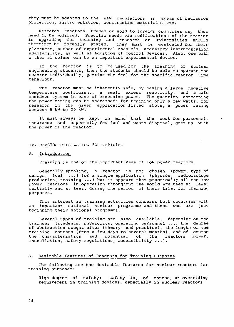
The reactor must be inherently safe, by having a large negativetemperature coefficient, a small excess reactivity, and a safeshutdown system in case of excessive power. The question concerningthe power rating can be addressed: for training only a few watts; forresearch in the given application listed above, a power ratingbetween 5 kw to 30 kW.
It must always be kept in mind that the cost for personnel,insurance and especially for fuel and waste disposal, goes up withthe power of the reactor.
IV. REACTOR UTILIZATION FOR TRAINING
A. Introduction
Training is one of the important uses of low power reactors.
Generally speaking, a reactor is not chosen (power, type ofdesign, fuel ...) for a single application (physics, radioisotopeproduction, training ...) but it appears that practically all the lowpower reactors in operation throughout the world are used at leastpartially and at least during one period of their life, for trainingpurposes.
This interest in training activities concerns both countries withan important national nuclear programme and those who are justbeginning their national programme.
Several types of training are also available, depending on thetrainees (students, physicists, operating personnel ...) the degreeof abstraction sought after (theory and practice), the length of thetraining courses (from a few days to several months), and of coursethe characteristics and potential of the reactors (power,installation, safety regulations, accessibility ...).
B. Desirable Features of Reactors for Training Purposes
The following are the desirable features for nuclear reactors fortraining purposes:
High degree of safety: safety is, of course, an overridingrequirement in training devices, especially in nuclear reactors.
14

Ease of operation: training reactors should be designed so thata minimum number of restrictions are imposed on the students andinstructors (for example, the control console can be operatedsafely by inexperienced students after a short instruction time).
Ease of maintenance: equipment should be arranged to provideeasy access for maintenance, and components should be selectedfor life and minimum maintenance.
Ease of experiments for students and instructor: for trainingreactors, ease of a wide variety of training and researchexperiments for students is highly desirable.
C. Training Programmes
It is difficult to give an outline of the training programmes runon low power nuclear reactors without taking into account thetrainees involved (students, physicists, operating personnel ...) ormentioning the possibilities and limitations offered by each type ofreactor (power, accessibility, flexibility ... ).
In order to make the presentation not too complicated, thefollowing classification may be proposed.
Training students and physicists
Low Power Reactor (< 1 MW). This type of reactor (< 1 MW)enables training to be given on:
- nuclear radiation measurement and application (activity, dose,half-life, energy, reaction with materials, activation analysisand statistics ...);
- reactor theory, neutron transport (by using, for example,spectrometer, neutron chopper, foil activation dosimeters ...);
- reactor kinetics, reactor dynamics (by experiment, detectorpulses ...);
- plant operation and control (by using an associated computer tosimulate the reactor operation and control).
Besides the above exercises, other types of exercises arepossible. The following are particularly worth mentioning:
- criticality and power increase of the reactor- relative and absolute flux measurements- reactivity measurements- control rod calibration- temperature coefficient measurement- poisoning effect measurement- spectrum measurement- void coefficient determination- radiation protection and shield measurement- neutron radiography- analysis by activation- radioisotope determination
Training operating personnel
Generally speaking, the emphasis is placed on all the proceduresand operations involved in reactor operation and safety, in
15
particular:
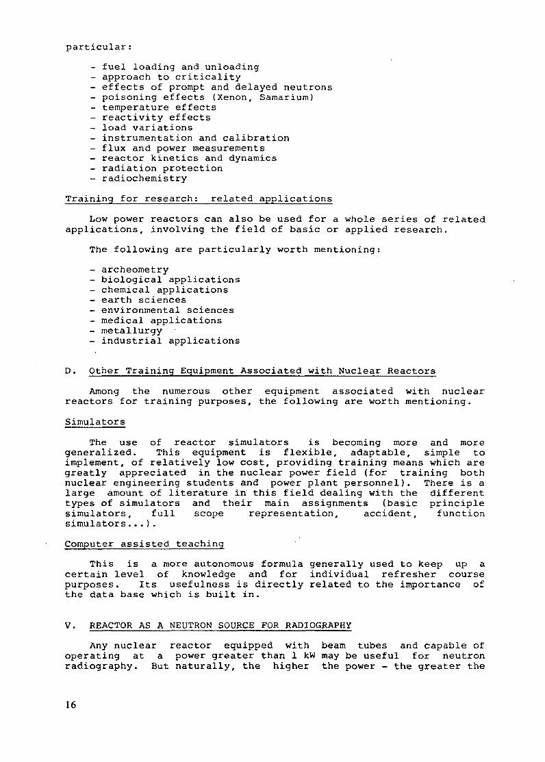
- fuel loading and unloading- approach to criticality- effects of prompt and delayed neutrons- poisoning effects (Xenon, Samarium)- temperature effects- reactivity effects- load variations- instrumentation and calibration- flux and power measurements- reactor kinetics and dynamics- radiation protection- radiochemistry
Training for research: related applications
Low power reactors can also be used for a whole series of relatedapplications, involving the field of basic or applied research.
The following are particularly worth mentioning:
- archeometry- biological applications- chemical applications- earth sciences- environmental sciences- medical applications- metallurgy- industrial applications
D. Other Training Equipment Associated with Nuclear Reactors
Among the numerous other equipment associated with nuclearreactors for training purposes, the following are worth mentioning.
Simulators
The use of reactor simulators is becoming more and moregeneralized. This equipment is flexible, adaptable, simple toimplement, of relatively low cost, providing training means which aregreatly appreciated in the nuclear power field (for training bothnuclear engineering students and power plant personnel). There is alarge amount of literature in this field dealing with the differenttypes of simulators and their main assignments (basic principlesimulators, full scope representation, accident, functionsimulators...).
Computer assisted teaching
This is a more autonomous formula generally used to keep up acertain level of knowledge and for individual refresher coursepurposes. Its usefulness is directly related to the importance ofthe data base which is built in.
V. REACTOR AS A NEUTRON SOURCE FOR RADIOGRAPHY
Any nuclear reactor equipped with beam tubes and capable ofoperating at a power greater than 1 kW may be useful for neutronradiography. But naturally, the higher the power - the greater the
16

source flux - the more convenient the methods and the better theradiographs.
A high quality radiograph is known to be composed of some 109quanta or registrations per square centrimetre on average. On theother hand, as few as 104 quanta or registrations per squarecentimetre are sufficient to produce a recognizable image of a widevariety of everyday objects. Thus, if we have an image recorder witha thermal neutron registration efficiency of 10%, the system must bearranged so that between 105 and 1010 n/cm-2 are incident on theimage plane in a reasonable time.
The neutron beam is directed onto the sample by simply allowingit to pass through a specially constructed opening in the reactorshielding, the collimator. Collimators are characterized by theirL/D ratio, where L is the source-to-detector distance and D is thewidth of the source aperture (the opening at the source end of thecollimator). The larger the L/D ratio, the greater will be thepotential geometric resolution of the system: the images of thickobjects will be sharper for improved collimation. On the other hand,improved collimation decreases the available neutron intensity.
A high quality radiograph for a thick (> 10 cm) object needs ahigh L/D ratio (> 200), which can be realized only at a reactor inthe MW range. Lower quality or radiographs of thin objects caneasily be obtained at small reactors.
Epithermal energy neutrons have been used to obtain improvedneutron penetration of materials that have high attenuation forthermal neutrons. The most widely used application involves neutroninspection of enriched reactor fuel. The increased penetration overthermal neutrons, often a factor of about 40, provides images showinginternal fuel details such as cannot be revealed by thermal neutronsbecause of their higher attenuation. Similar penetration advantagescan be demonstrated in other materials such as those containinghydrogen. An advantage of resonance neutrons for radiograph is thesignificant increase in detectability for a given material.
Significant energy tailoring neutron beams for radiography isrestricted to reactors in the MW range. Epithermal neutronradiography (Cd filtered beam), however, can be available in the kWrange with an irradiation time of a few hours. In all of the cases,the main advantages of a small reactor are the low radiation levels,flexibility, and much lower cost. Testing highly irradiatedmaterials (fuel), however, may cause problems in a universityenvironment.
VI. SOME REMARKS ON THE SAFETY OF LOW POWER RESEARCH REACTORS
Besides being versatile and of a wide scope of application, manylow power research reactors have unique user-friendly safetyfeatures. For the reactors discussed in this meeting, most of themhave a large negative temperature coefficient of reactivity(10-4 A k/k/°C) and void coefficient due either to the undermoderation of the core or in some cases, (e.g. TRIGA) to theincrease of neutron temperature by the crystalline effect of themoderator used (ZrH). This negative temperature coefficient iseffective in limiting the power excursion during a sudden insertionof reactivity. For TRIGA reactors, since this coefficient is promptdue to the intimate mixing of the fuel and moderator, a largeinsertion of reactivity can pulse the power of the reactor to a veryhigh value while the self limiting property of the prompt negative
17

temperature coefficient quickly brings down the power surge so thatthe temperature rise of fuel is limited to a safe level. While forother reactors of water moderation, (e.g. Slowpoke, MNSR), thetemperature coefficient is mainly due to the moderator heating up andis not as prompt. A sudden reactivity insertion will lead to aninstant power surge and the temperature of the fuel will rise. Withgood thermal conductivity between the fuel and the cladding, heatwill quickly be transferred to the cooling water raising thetemperature of water and the moderator negative temperaturecoefficient will come into play and decrease the excess reactivity.The reactor power will settle down to a level determined by theinitial reactivity and the negative temperature coefficient togetherwith the coolant flow rate. As a result the power surge will bequenched which in turn will limit the rise of the fuel temperature.
Secondly, being of low power, built-in reactivity can be keptquite low, mostly for compensation of temperature rise, Xe poisoningand sample loading with a small investment for fuel burn-up. In manylow power research reactors, this low excess reactivity coupled witha large negative temperature coefficient of reactivity and limitedcoolant flow rate, limits power level and fuel temperature to safevalues for power transients which may happen. This self-limiting andself-regulating behaviour of reactor power make such reactorsinherently safe. These inherent safety features are valuable forsafe operation of low power research reactors (cf. papers in thismeeting).
Notwithstanding these inherent safety features, one cannot reallydesign and construct a completely foolproof reactor without takingdue account of foreseeable human and equipment failures. It isgenerally agreed for nuclear safety that reactors should follow the
defense in depth approach to guard against inadvertant release offission products from the fuel to the environment and to personnel.Thus, as a first level of defense, one must pay attention to careful
design, construction, operation and maintenance so that malfunctionswhich could lead to accidents will be unlikely. For this purpose onemust use established and conservative engineering practices and withadequate margins of safety in design, high quality construction andmanufacturing, excellence in operation, use of tested components andmaterials, etc. As a second level of defense, one must have means to
protect against possible human or equipment failures. For example,in case of jamming of the shutdown rod(s), it should still bepossible to shut down the reactor safely by other means. Usually one
requires that in case of failure of one safety-related component or
system, the safety function is not impaired (single failure
criterion), either by redundancy and/or by built-in inherent safetyfeature. For a low power research reactor, a serious accident mightcause some damage to reactor fuel with some release of fissionproducts, for example, through blockage of fuel cooling channel by a
loosened part in the reactor core. To avoid such accidents, the bestpolicy is to take preventive safety measures especially in qualityassurance of important equipment during maintenance and routinesurveillance, qualification and adequate training of operators, and
detailed analysis of abnormal event and taking due correctivemeasures.
Taking into account the knowledge and experiences gained insafety and with adequate regulatory measures, we believe that safetyof low power research reactors can be ensured and incidents or
accidents should be rare and could be harnessed in an acceptablyharmless way, even if not completely eliminated.
18

CONCLUSIONS
Advantages of LPR's:
Low capital cost. The exact cost information for these reactorsis not available since most of them have been installed for a numberof years. Best estimates for the less than 30 kW reactors range fromabout US$ 400,000 for the simplest reactor to about 1 to 1.5 millionUS dollars. This compares to a price of about 5 million US dollarsfor a reactor of several hundred kilowatts power. The lower end ofthe price range depends on the amount of local design andconstruction performed. The available option, i.e. experimentalfacilities, instrumentation, etc., could significantly influence thecost.
Low operating cost. The operating cost of the reactorsrepresented are in the range of US$ 100,000 per year and less.However, because of differences in economic conditions, it may bemore reasonable to express this in terms of personnel requirements.This usually includes, as a minimum, one operator, one supervisor(part-time), and repair, maintenance and radiological protectionservices, from the overhead of the institute in which the reactor islocated. The experience of the participants has been that thesereactors are very reliable and relatively free of problems. Thefailure rate of reactor components is typically less than one peryear. Annual cost for consumible supplies is estimated at$10-15,000.
Low' burnup. Because of the low operating power, the fuel burnupis extremely small and most reactors in this class have "lifetime"cores. In the Slowpoke- and MNSR-type reactors, reactivityadjustments are made by adjustment of the beryllium shims. The lowburnup and limited radioisotope production capability result inminimal radwaste problems.
Simple to operate. This class of reactor of simple design iseasy to operate and requires little operator training. The two 100kW reactors, designed for operator training, are more complex andrequire correspondingly more detailed training.
Safe. These reactors are relatively safer to operate than thelarger reactors. The smaller reactors (P < 27 kW) are power limiteddue to the negative temperature coefficient. All are able towithstand a loss of coolant accident. Occupational radiation dosesare also lower. As with all reactors, however, any fuelmanipulations must be carefully supervised.
Less restrictive containment and siting requirements. Because ofthe low fission product inventory, safety in reactivity transientsand in loss of coolant accidents, the siting and containmentrequirements for this class of reactors is much less restrictive.Most of the reactor facilities discussed at the meeting were housedin normal buildings (with controlled access) and in populated areas.However, the matter of siting and containment must be left to thenational authorities where the reactors will be located.
Versatility. These reactors are very well suited for trainingactivities because of the flexibility of scheduling use. The freedomto startup, shutdown or change operating power is usually not foundin larger reactors. These .reactors are also excellent tools for
19

neutron activation analysis, as evidenced by the papers appended tothis report. These reactors have also been active in the developmentof nuclear detection instrumentation.
Disadvantages of LPR's:
Lower sensitivity for NAA. Naturally, because of the loweravailable flux, the sensitivity for NAA is less. However, this lowersensitivity also can result in less interference from ions that arenot activated to as great an extent.
Limited radioisotope production. Production of radioisotopes islimited to those with short half-lives, for use in calibration,teaching or research.
Limited use of neutron beams. Performance of neutron diffractionand scattering experiments is limited. This is also true for fastneutron studies.
Limited access to the core. In some of these reactors, the coreis not normally accessible. While this adds a measure of safety,this inhibits some experiments in reactor physics.
Licensibility. The simple instrumentation and control system forsome LPR's may present a problem of licensing in some countries.This may be the case for the Slowpoke and MNSR where there is asingle control rod thereby violating safety criteria in somecountries.
20

PAPERS PRESENTED AT THE MEETING
THE ZERO POWER REACTOR SURAND ITS APPLICATION
U. WESSERInstitut fur Kerntechnik,Technische Universitat Berlin,Berlin (West), Federal Republic of Germany
Abstract
This low-power reactor, rated nominally at 100 milliwatts, has acylindrical core of 26 cm in diameter and 24 cm high consisting ofU308 powder in a polyethylene matrix. The fuel is 20 percentenriched and the critical mass about 700 g. The excess reactivity isabout 3 mk. The reactivity is controlled by two cadmium sheets inaddition to a back-up system that drops the inner reflector. The reactorhas no active cooling system. Personnel costs include a supervisor andan operator. The reactor is used for training in Reactor Theory(including use of a neutron chopper), reactor kinetics, nucleartechnology, reactor operations and for doctoral thesis research.
I. Sunimary
In the field of reactor development it is evident that the em-
ployed physicist or engineer need not have any extensive special
knowledge of nuclear technology to work with success. The most
emphasis is placed on training in the respective discipline,
e.g. physics, electrical engineering, heat and fluid dynamics,
mechanical engineering. But, in addition, knowledge of basic
principles of nuclear theory and technology is advantageous for
mutual understanding and for teamwork between the expert groups.
Particularly in this sector of science, it is necessary to com-
muniate the most important features with the help of well pre-
pared reactor training courses.
The alternatives - power research reactor or zero power reactor
or subcritical assembly are often discussed.
Research reactors are recommended for long living well organiz-
ed programs are staffed with operators and are operated twenty
four hours day by day at full power. A subcritical assembly is
a facility for the investigation of definite problems dealing
21

with neutron physics and core technology. In both cases power
research reactor and subcritical assembly we have to recognize
the possibility of dangerous excursions so that the training of
students is often restricted to a state of observers during re-
actor operation.
The Technical University of Berlin possesses a SUR low power
reactor since 23 years. In spite of the very low power of 0.1
watt it is a very important device in the training program for
students of nuclear engineering.
Compared with other reactor types and subcritical assemblies
one can point out:
- The absolute safety against any kind of power excursions
- negligible radiation and no problems with waste
- low operating costs.
The reactor SUR provides the students with a good feeling for
the special behaviour of nuclear reactors. They are allowed to
operate the reactor without any restriction after a short in-
struction time.
A brief description of our training program is given in this
paper.
II. Description of the Reactor
The main parts are (Fig. 1):
- Core with fuel and moderator
- reflector
- shielding y and neutron
- controldivices control rods
separation of core halves
- instrumentation nuclear and safety
- experimental devices horizontal and vertical channels
thermal column
22
8
9k
ttc
lOb
11
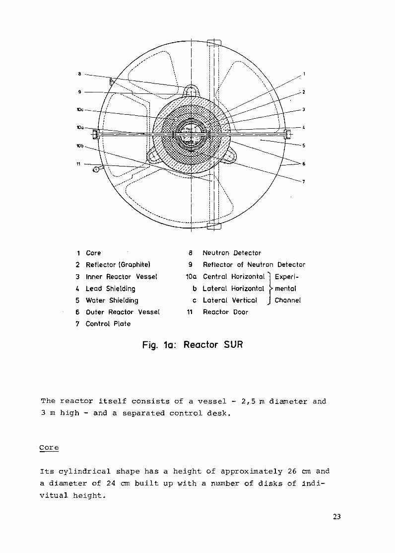
1 Core
2 Reflector (Graphite)
3 Inner Reactor Vessel
4 Lead Shielding
5 Water Shielding
6 Outer Reactor Vessel
7 Control Plate
Fig. la:
8 Neutron Detector
9 Reflector of Neutron Detector
10a Central Horizontal Experi-
b Lateral Horizontal mental
c Lateral Vertical JChannel
11 Reactor Door
Reactor SUR
The reactor itself consists of a vessel - 2,5 m diameter and
3 m high - and a separated control desk.
Core
Its cylindrical shape has a height of approximately 26 cm and
a diameter of 24 cm built up with a number of disks of indi-
vitual height.
23

I_
2
3
5-
9
6/
7-
--- -- - --- - -- --
______ _ ...
N; ·· · ·-, i ·// ·* /'~
Z~rgI /~~
i~v
hl�
�'k�
·�:"
j
MiHl' ....WRt/-~
1.4i
- - _ .. -1T
It
i 11
I·:·S·:·.·�: XIt, 'r ·�:
J * '
:-. . .__
: .- - - '.'_. ...
:_-_ _ _"
:--
~__
: -- - - -::_-::... ___
:_- _:_-::
: _ - ' _ _:--..7
: :Z.--- .'.-.: _' _ -f-
t14
----- 12
--7 10
I---5
-- 13
j t f=. = -. --.--,
! I .I I1 , · - - -
1 Core2 Reflector (Graphite)
3 Inner Reactor Vessel
4 Lead Shielding5 Water Shielding
6 Control Plate7 Drive for Control Plate
9 Reflector of Neutron Detector
10 Experimentation Channel
11 Thermal Column12 Neutron Source13 Drive for Neutron Source
14 Hoist for Reactor Core Half
15 Motor for Hoist
8 Neutron Detector
Fig. 1b: Reactor SUR
24

The core consists of a highly compressed mixture of U 30 8 and
polyethylene powder. The fuel is enriched up to 20 % with the
fissile isotope 235 U. Polyethylene has a high hydrogen con-
tent and acts as moderator and its large thermal expansion
coefficient provides an exceptional inherent safety. The critic-
al quantity is about 700 g 235 U and the excess reactivity is
usually about 0,3 % or about 0,5 $ and is determinated by
critical experiment.
The lower half of core can be moved about 5 cm down such that
the criticality is decreased about 5 % or 8 $ to an absolute
safe shut down state.
Reflector
The reflector surrounds the core in a 20 cm thick layer and
consists of highly purified graphite. There are an inner and
an outer reflector. Between both an aluminium tank is provided
which acts as a barrier for gaseous fission products.
Shielding
The shielding consists of a 10 cm wall of lead. About 95 % of
all -- quants leaving the reflector from fission products and
other neutron reactions are here absorbed. But the lead is no
absorber for neutrons and therefore the ring shaped room
between the inner and outer reactor vessel is filled with boric
acid saturated water. This solution acts as a moderator for
fast neutrons and as a absorber for thermal neutrons.
If necessary the room under the core can be filled up with
some layers of borated polyethylene disks to prevent neutron
radiation into the ground of the reactor. The thermal column
is covered with a 2,5 cm thick layer of borated polyethylene.
Fig. 2 shows the radiation fields around the reactor.
25

0.7- 2ar
-2 1 2
Distance from Reactor Axis [m]--
----- Curves of Constant y-Dose [mr/h]
[--I Neutron Radiation [mrem/h]
Fig. 2: Radiation Field of SUR, Power 0,1 W
Controldevices
The two control plates are located outside of the core in the
reflector and both are capable to shut down the reactor in any
case. They consist of Cadmium sheet as neutron absorbers, are
moved by a motor with gears and, if scrammed, the plates are
quickly driven by springforce to the position nearest the core
(Fig. 3).
Cadmium Plate
I-1
Fig. 3: Control Rod Drive
26

The second fully independent safety system is the movable lower
core half plus lower inner reflector part. The core hoist con-
sists of geared rack and ponion drive with electromagnetic
coupling. In case of shut down the core half drops in less
than one second down with an effective reactivity value of
about - 8 $ (Fig. 4).
Fig. 4. Core Hoist and Neutron Source Drive
Instrumentation
The nuclear instrumentation is used to display to monitor and
to registrate the operating status of the reactor. The power
level depends of neutron flux so that the neutron flux is
monitored for control reasons. Under start conditions the
power is logged by pulse-channels with BF 3 counters. If the
power is increased, the DC channels are activated. Here two
compensated BF 3 ionisation chambers are in use, one for a lo-
garithmic and the other for a linear channel.
27

Fig. 5 shows the scheme of the instrumentation. In addition to
the flux the reactor period is determinmated from the loga-
rithmic neutron flux. The period is a direct measure for the
change of neutron flux per time interval.
y-channels take care of measurement and monitoring the y-dose
rate in the direct vicinity of the reactor and the control
desk near the place of the operator.
Discriminotor . Log. count rote meter Period Instrument
-EMinimum source strength
Multiplicotion
Audible preworning
Scram
Minimum flux density
Switch off counters
Scram
High-voltoge monitoring
Instrument monitoring
Audible preworning
Scram
High-voltoge monitoring
Portiol scrom
High-voltoge port Lineor count rote meterttih omplhier
Fig. 5: Nuclear Instrumentation
Before starting of the reactor all instrumental functions are
checked as well as the recommended status of the reactor. An
electronic interlocking system connected with the neutron and
radiation channels allows starting and operating the reactor
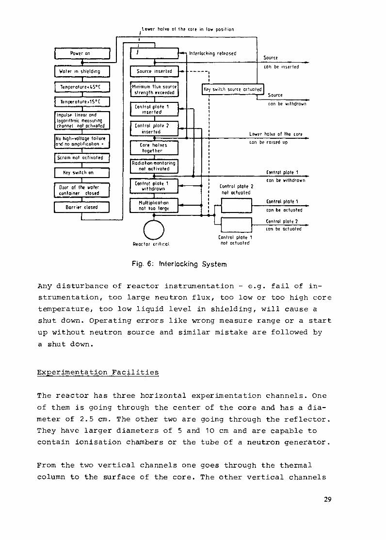
only in the permissible manner (Fig. 6).
28
Lower holve of the tore in low position
Control plote 1not actuotedReactor crittcol
Fig. 6: Interlocking System
Any disturbance of reactor instrumentation - e.g. fail of in-
strumentation, too large neutron flux, too low or too high core
temperature, too low liquid level in shielding, will cause a
shut down. Operating errors like wrong measure range or a start
up without neutron source and similar mistake are followed by
a shut down.
Experimentation Facilities
The reactor has three horizontal experimentation channels. One
of them is going through the center of the core and has a dia-
meter of 2.5 cm. The other two are going through the reflector.
They have larger diameters of 5 and 10 cm and are capable to
contain ionisation chambers or the tube of a neutron generator.
From the two vertical channels one goes through the thermal
column to the surface of the core. The other vertical channels
29

are going through the reflector and can be used for a third
control rod, if automatic reactor control is prefered. If not
used, all channels are closed with fillers of graphite lead or
polypropylene.
The thermal column is another experimentation facility designed
to study neutron transport phenomenes.
It consists of an aluminium container - height 55 cm, diameter
85 cm - normally filled with graphite, which can be easiliy
replaced by other moderators like water or organic liquids.
III. Operating Costs
The reactor can be installed in normal laboratories without
special conditions caused by radiation, air or water contamina-
tion or handling of waste.
A place of six to ten meters is sufficient for training of
students. Only the weight of 15 tons is to be taken into con-
sideration. The personal costs include the expenditure for the
persons responsible for the reactor, generally a physicist or
engineer with university degree and one assistant as a reactor
operator. There are no fuel costs for refilling. The power con-
sumption is about three kW.
The costs for insurance in West Germany are about $ 7.000,--
per year. Other costs arise from experimentation equipment used
for student training. One can start without special devices
using only the normal electronic equipment, but it is possible
to construct and build special devices like:
Control rods and controllers, pile oscillators, neutron spectro-
meter, neutron chopper and others.
IV. Application of the Reactor
The reactor is used for student training in an engineering de-
partment and belongs to the Institute fo Nuclear Engineering.
30

The training courses are a part of the lessons given in the
institute which are:
Nuclear Radiation,Measurement and Application
Reactor Theory - Neutron Transport
Reactor Kinetic and Dynamic
Plant Operation and Control.
A reactor course with the same name belongs to each of these
lessons.
Nuclear Radiation Measurement and Application
In this course for beginners the student learns the use of in-
struments to measure the properties of radiation like:
activity, dose, half life time, energy, reaction with matters,
activation analysis and statistics; furthermore, production
and handling of open and sealed radioactive probes. The reac-
tor is used for production of radioactive isotopes from
Ag, Br, Co, Dy, Eu, In, Mn, Rh, V, ...
in quantities and specific activities sufficient for measure-
ment training.
In the case of activation analysis a secure demonstration of
small quantities of Al, Cl, Cu, J, K, Mg, Na, ... is possible.
In the center of the core is a neutron flux density of
106 n cm-2 -16 * 10 n cm s
Under this condition longer living isotopes e.g.
Au + Th = 2,7 d have a specific activity of 0,42 pC g after
a radiation time of one hour.
Short living isotopes with high activation cross sections like
Indium builds up the higher specific activity of 53 pC g-.
But in this case the half life time is shorter than one hour.
So we have in both cases no trouble with waste and contamina-
tion. One day later we have always "clear conditions" in our
laboratories.
31

Reactor Theory - Neutron Transport
The first group of experiment treats neutron energy measure-
ment and neutron reactions with matter.
It starts with the simple measurement of neutron energy using
energy dependent activation foils. In spite of the very rough
energy distribution this is an effective experiment, because
a good comparation with neutron theory is possible.
The next step is the use of a crystal spectrometer. The scatter-
ed neutrons are registrated with an analyser system. The angle
depending count rate shows the energy distribution of neutrons.
In case that the neutron beam extracted from the reactor is
filtered by thin film-like foils it is possible to measure the
cross section of foil matter.
The best results of energy mesurement are obtained by using a
neutron chopper in a "time of flight" experiment. In spite of
the very short flight way - less than two meters - the results
for thermal and intermediate neutrons are comparable with the
results from multigroup diffusion calculation and from simple
transport theory. The determination of cross section, especial-
ly for 1/v absorbers showed satisfying results. The second
group of experiments considers the neutron transport in non-
multiplying and in multiplying materials.
The diffusion behaviour of neutrons in the thermal column is
inquired by cadmium covered and uncovered Au-foils. The results
are three-dimensional fields of thermal and intermediate neu-
trons fluxes in the graphite column. These can be compared to
results of diffusion theory.
The distribution of neutrons in the core is also determinated
by foil activation. The first step is the activation of cover-
ed and uncovered foils along the core axis. The relative neu-
tron distribution is the result. Later on in a second step a
foil is activated in the center of core. The absolute activity
is determinated by coincidence technics. The absolute neutron
32

flux distribution can be calculated with the result of this
measurement and the power of the reactor is known. The result
is comparable to a two-group computation for cylindrical core
geometry.
1,0
ncr-2 -1
08
0,6
01 Fost neutron flux density
02 Thermol neutron flux density
Graphite reflector Leadshielding
Water shielding
0,4
0
0 10 20 30 40 50 60cm
r t
Fig. 7: Relative Neutron Flux Distribution
Reactorkinetic - Reactordynamic
The first group includes all the main experiments dealing with
time behaviour of the neutron population in undercritical and
critical status. The neutron chains in the undercritical state
are observed by
Rossi a-experiment
Feinman a-experiment
distribution of detector pulses
variance to mean and so on.
33

Similar results are obtained using a pulsed neutron source. In
the critical state of the reactor the determination of reactivi-
ty is possible by Rod Drop and Source Yerk experiments. A number
of experiments are established to measure the overall time be-
haviour of the reactor. The reactivity is modulated by use of
a pile oscillator over a range of frequencies.
The transfer function in magnitude and phase is the result and
shows the lifetime of neutrons and the influence of delayed
groups. The analysis of neutron noise is a more sophisticated
experiment using time series or correlation analysis to com-
pute the power spectral density.
Plant Operation and Control
The simulation of the reactor with analog computer is the pre-
paration of the control experiments. The influence of different
controller parameters setting up to instability of the simulated
reactors are observed and discussed.
Next steps are done on the reactor. A control circuit with a
separate control rod in a vertical experimental channel is
established.
Here we substitute the controller by analog computer. Later on
we use an industrial controller. The application of a modern
digital computer follows. It can be programmed to control the
reactor in many kinds of modern control theory and acts also
as data monitor of reactor and so on.
Besides the courses the reactor is often used for doctor thesis
works. Many works are done with neutron noise and reactor con-
trol. Here the main advantage of the reactor is the missing
cooling. The neutron population is only influenced by statistic
of fission and follows the theory of reactor kinetic.
34

V. Reactor Data
Power
Maximal thermal neutron flux (Fig. 7)
Life time of neutrons
Max. radiation on wall of outerreactor vessel
Neutron dosis on thermal columnunderside
y-dosis on thermal column underside
burn up of uranium in one yearfull power
reactivity control rod
reactivity core halves separation
temperature coefficient
100 mW
6 * 106 N cm 2 s- 1
4 · 105 s
< 2,5 mrem h
10 rh1
10 r h100 r h - 1
30 ig 235 U Y
' 0,6 $
- 0,034 grd- 0,034 % grd 1
Remarks
The reactor can be used without any change at higher power
levels up to ten watt, if the shielding is reinforced by a
wall of concrete blocks around the reactor vessel.
35

APPLICATIONS OF A LOW POWER NUCLEAR REACTOR
A.J. BLOTCKYVeterans Administration Medical Center,Omaha, Nebraska,United States of America
Abstract
The Omaha Nebraska Veterans Administration Medical Center (OVAMC) TRIGA
reactor is a research reactor designed and fabricated by General Atomic. The
reactor first achieved criticality on June 30, 1959. It is a below grade,
open-tank-type, light water moderated, cooled, and shielded reactor that
currently is authorized to operate in the steady-state mode at thermal power
levels up to 18KW with an excess reactivity limitation of 0.79% Delta K/K.
REACTOR CORE
The reactor core consists of a relatively compact array of standard
aluminum clad TRIGA fuel elements, graphite dummy elements, three boron carbide
control rods, control rod guides, an americium beryllium neutron startup source,
and irradiation facilities (Fig. 1). The fuel elements are spaced so that about
33% of the core volume is occupied by water, yielding a fuel-to-water ratio
resulting in a critical mass near the minimum value for 20% enriched uranium
fuel. The elements are held in concentric rings by an upper and a lower grid
plate. The reactor currently requires 56 fuel elements to achieve criticality
and to provide the authorized excess of reactivity (0.79% Delta K/K) necessary
to meet operating requirements. The balance of the 85 fuel element positions are
occupied by experimental facilities or graphite-reflector elements. The latter
are elements in which the U-ZrH fuel is replaced by graphite.x
The reactor core geometry of the Omaha VAMC reactor is similar to that of
most of the 58 TRIGA reactors in operation throughout the world, 27 of which are
in the United States. However, the cladding for the OVAMC reactor fuel is
37

,,,, t tl M ltf{
911 •in . « &~ I-IC
niOlllit -**nrI1sft1$srtif
4
Fig. 1. Elevation view of TRIGA Mark 1 Reactor
aluminum, which was used only in the first few TRIGA reactors. The instruments
and control are similar to those on other research reactors licensed by the U.S.
Nuclear Regulatory Commission. The core is surrounded by a cylindrical graphite
reflector that is completely encased in a welded aluminum container. Flooding
of the reflector container because of a leak would decrease reactivity.
FUEL ELEMENTS
The active part of each aluminum clad TRIGA cylindrical fuel element (Fig.
2) is approximately 3.6 cm in diameter by 0.36 m long and is a solid homogenous
38

I
,-ALUMINUM TOP £ND-FIXTU
-- PACER
I to eRN
RHI
PHI TE
28.44 IN. , 14.0
ALUMINUM BOOTTOM EOD-flXTU~E
Fig. 2. TRIGA fuel-element assembly
1ABLE POISON
001 N
r- ZIRCONWiUHYORiDE,
8 WT-%URANi
PHITE
IK
mixture of a U-ZrH alloy containing 8 weight-percent uranium enriched to lessx
than 20% in 235U. The hydrogen-to-zirconium ratio is approximately 1.0. A thin
aluminum wafer at each end of the active fuel contains samarium oxide as a
burnable poison. Each element is jacketed with a 0.076-cm-thick aluminum can.
Ten-cm sections of graphite are inserted in the can above and below the fuel to
serve as top and bottom neutron reflectors for the core. Aluminum end fixtures
are attached to both ends of the can. The overall length of each element is
approximately 0.72m. Visual examination of fuel elements on a quarterly basis
has shown no indication of any deterioration or swelling. The alternative
39

stainless-steel cladded element which is the current standard is identical to
the aluminum clad element with the exception that the hydrogen-to-zirconium is
approximately 1.65 to 1.7 and the active part of the fuel element is 0.38 m
long. The burnable poison is aluminum-samarium and the cladding is 0.05-cm-thick
stainless steel.
CONTROL RODS
The power levels in the reactor are regulated by three boron-carbide
control rods. The control rods operate in perforated aluminum guide tubes. The
guide tubes are attached to the bottom grid plate, and the upper grid plate
provides lateral support. Each control rod has an extension tube that connects
to a drive mechanism through an armature and electromagnet system (Fig. 3). One
control rod, designated as the safety rod, is completely withdrawn during
NOTE:
ALUMINUM COVER ON TOP MAGNET WIE CONDUITor DRIVE ASSEMBLY ISNOT SHOWN.
MAGNET DRAW TUBE-WITH RACK
MOTOR COVER-
PULL-ROD HOUSI
PULL ROD-
-POTENTIOMETER COVER
-BLOCK
-BARREL
-MAGNET DRAW TUBE
-MAGNET
.ARMATURE
-CONNECTING ROD
Fig. 3. Control-rod drive mechanism
40

operation and is worth approximately 1.5% Delta K/K. The other two control rods
are worth approximately 1.5% Delta K/K and 0.36% Delta K/K respectively.
REACTOR TANK
The reactor is near the bottom of a below-grade cylindrical pit (Fig. 1)
located in the basement of the 12-story OVAMC hospital building. The pit
contains a 2.1 m-inside diameter steel tank with a 0.64 cm-thick wall. The tank
rests on a 0.28 m-thick concrete slab. A 0.25 m-thick poured concrete wall
surrounds the outside of the tank. The concrete slab and wall provide a
protective barrier between the tank and the surrounding soil. The inside of the
tank is covered on the sides by a layer of pneumatically applied mortar
approximately 5 cm thick and the bottom by a layer of poured concrete
approximately 10 cm thick. The entire inner surface is coated with two
applications of waterproof epoxy resin coating. Visual observation of the tank
with binoculars shows no evidence of deterioration of the tank during the past
26 years. The reactor tank contains approximately 15,140 liters of deionized
water with a normal shielding depth of 4.9 m above the top grid plate. The
natural thermal convection of this water adequately dispenses the heat generated
in the core by the normal operation of the reactor. The pool water is pumped at
38 1/min through a 60,000 BTU/hr chiller unit that ultimately disposes of the
heat to the atmosphere outside of the Medical Center building. If the external
cooling system fails with the reactor operating at 18 KW the rate of rise of the
temperature of the water in the reactor tank will be less than 1°C per hour.
REACTOR COOLING SYSTEM
Cooling water flows from the reactor tank to a water monitor chamber where
temperature, conductivity, and gamma radioactivity are measured. The
circulating pump takes water from the monitor and discharges it through a
41

refrigerated heat exchanger, a 10 micron filter, a 85 liter mixed bed deionizer,
a flow meter and back into the reactor tank (Fig. 4). The cooling water loop
takes suction from the reactor pool at a point about 1 m below the pool surface.
Thus a piping rupture could draw the pool down only 1 m and would still leave
the reactor core adequately shielded.
Fig. 4. Reactor cooling system
REACTOR INSTRUMENTATION
The operation of the reactor core is monitored by four separate detector
channels. A fission chamber, two boron-lined compensated ion chambers, and a
boron-lined uncompensated ion chamber constitute the reactor core monitoring
system. These detectors monitor the neutron-flux density of the core and
provide trip signals to the safety circuits.
DYNAMIC DESIGN
The safe operation of a TRIGA reactor during normal operations is
accomplished by the control rods and is monitored accurately by the core
42
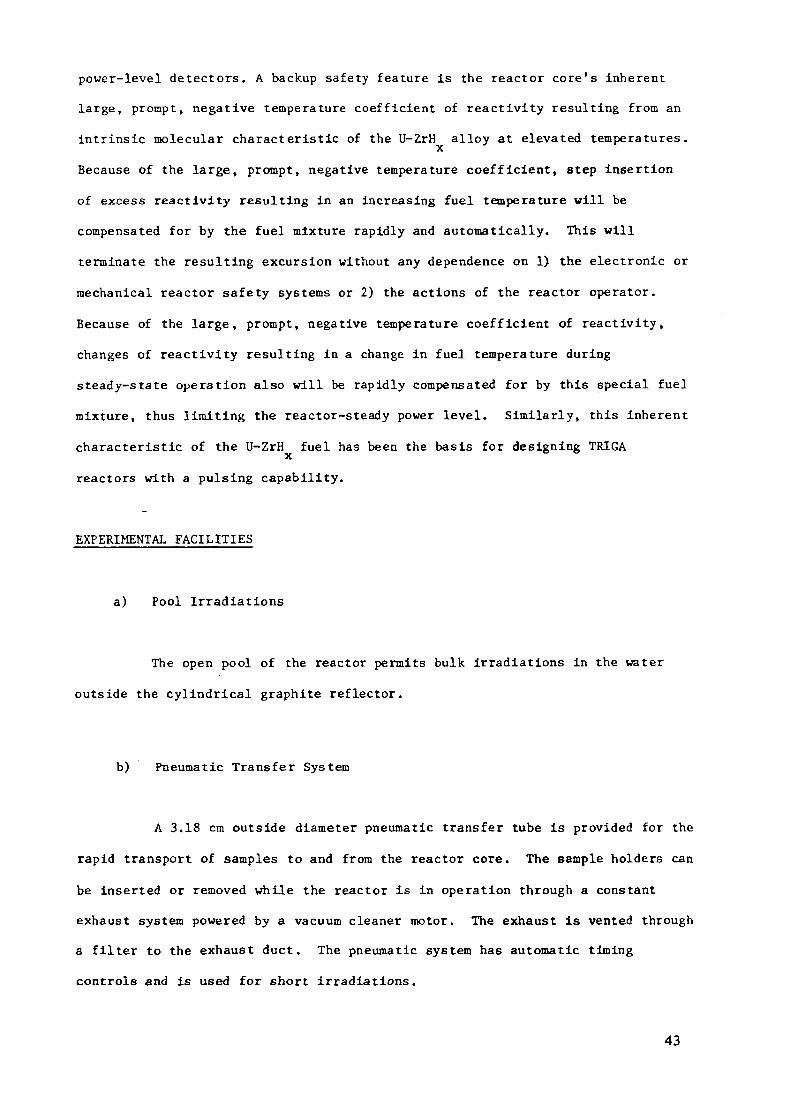
power-level detectors. A backup safety feature is the reactor core's inherent
large, prompt, negative temperature coefficient of reactivity resulting from an
intrinsic molecular characteristic of the U-ZrH alloy at elevated temperatures.
Because of the large, prompt, negative temperature coefficient, step insertion
of excess reactivity resulting in an increasing fuel temperature will be
compensated for by the fuel mixture rapidly and automatically. This will
terminate the resulting excursion without any dependence on 1) the electronic or
mechanical reactor safety systems or 2) the actions of the reactor operator.
Because of the large, prompt, negative temperature coefficient of reactivity,
changes of reactivity resulting in a change in fuel temperature during
steady-state operation also will be rapidly compensated for by this special fuel
mixture, thus limiting the reactor-steady power level. Similarly, this inherent
characteristic of the U-ZrH fuel has been the basis for designing TRIGAx
reactors with a pulsing capability.
EXPERIMENTAL FACILITIES
a) Pool Irradiations
The open pool of the reactor permits bulk irradiations in the water
outside the cylindrical graphite reflector.
b) Pneumatic Transfer System
A 3.18 cm outside diameter pneumatic transfer tube is provided for the
rapid transport of samples to and from the reactor core. The sample holders can
be inserted or removed while the reactor is in operation through a constant
exhaust system powered by a vacuum cleaner motor. The exhaust is vented through
a filter to the exhaust duct. The pneumatic system has automatic timing
controls and is used for short irradiations.
43

GRAPHiTEi Ft.EC IOR
Fig. 5. TRIGA Mark I Core Configuration
c) Rotary Specimen Rack (Fig. 5)
The rotary specimen rack consists of an aluminum ring (located at the
level of the top grid plate) that can be rotated around the core. Forty evenly
spaced aluminum cups are hung from the ring and serve as irradiation specimen
holders. The ring can be rotated manually from the top of the reactor pool so
that anyone of these cups can be aligned with the single isotope-removal tube
that runs up to the top of the reactor. An indexing and keying device is
provided to ensure positive positioning of the cups. The rotary specimen rack
is enclosed completely in a welded aluminum container which is designed to be
watertight. Flooding this container will decrease the reactivity of the reactor.
In order to maintain a constant neutron flux for all samples during a long
irradiation, a motorized drive continuously rotates the specimen rack.
44
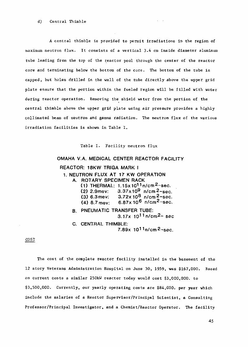
d) Central Thimble
A central thimble is provided to permit irradiations in the region of
maximum neutron flux. It consists of a vertical 3.4 cm inside diameter aluminum
tube leading from the top of the reactor pool through the center of the reactor
core and terminating below the bottom of the core. The bottom of the tube is
capped, but holes drilled in the wall of the tube directly above the upper grid
plate ensure that the portion within the fueled region will be filled with water
during reactor operation. Removing the shield water from the portion of the
central thimble above the upper grid plate using air pressure provides a highly
collimated beam of neutron and gamma radiation. The neutron flux of the various
irradiation facilities is shown in Table I.
Table I. Facility neutron flux
OMAHA V.A. MEDICAL CENTER REACTOR FACILITY
REACTOR: 18KW TRIGA MARK I1. NEUTRON FLUX AT 17 KW OPERATION
A. ROTARY SPECIMEN RACK(1) THERMAL: 1.15x1 1 n/cm 2 -sec.(2) 2.9mev: 3.37x10 9 n/cm2 -sec.(3) 6.3mev: 3.72x10⁸ n/cm2 -sec.(4) 8.7mev: 6.87x 10 6 n/cm2 -sec.
B. PNEUMATIC TRANSFER TUBE:3.17x 10 1 1n/cm2 - sec
C. CENTRAL THIMBLE:7.89x 10¹¹ n/cm 2 -sec.
COST
The cost of the complete reactor facility installed in the basement of the
12 story Veterans Administration Hospital on June 30, 1959, was $167,000. Based
on current costs a similar 250kW reactor today would cost $3,000,000. to
$3,500,000. Currently, our yearly operating costs are $84,000. per year which
include the salaries of a Reactor Supervisor/Principal Scientist, a Consulting
Professor/Principal Investigator, and a Chemist/Reactor Operator. The facility
45
has been very reliable requiring less than $250. per year in replacement parts
such as vacuum tubes, and other electronic and mechanical components.
Maintenance is done by the VA Research Service Electronics Unit.
FUEL UTILIZATION
An important advantage of a low power research reactor is the small amount
235of 2U burnt up. Since start up on June 30, 1959, the facility has been
235 235operated for 343 Megawatts and the total U burn up is 16.21 g 35U. The
235current enrichment is 19.66% and the average yearly burn up of 35U is 0.66 g.
235The original inventory of U was 2033.21 g with an enrichment of 19.8%.
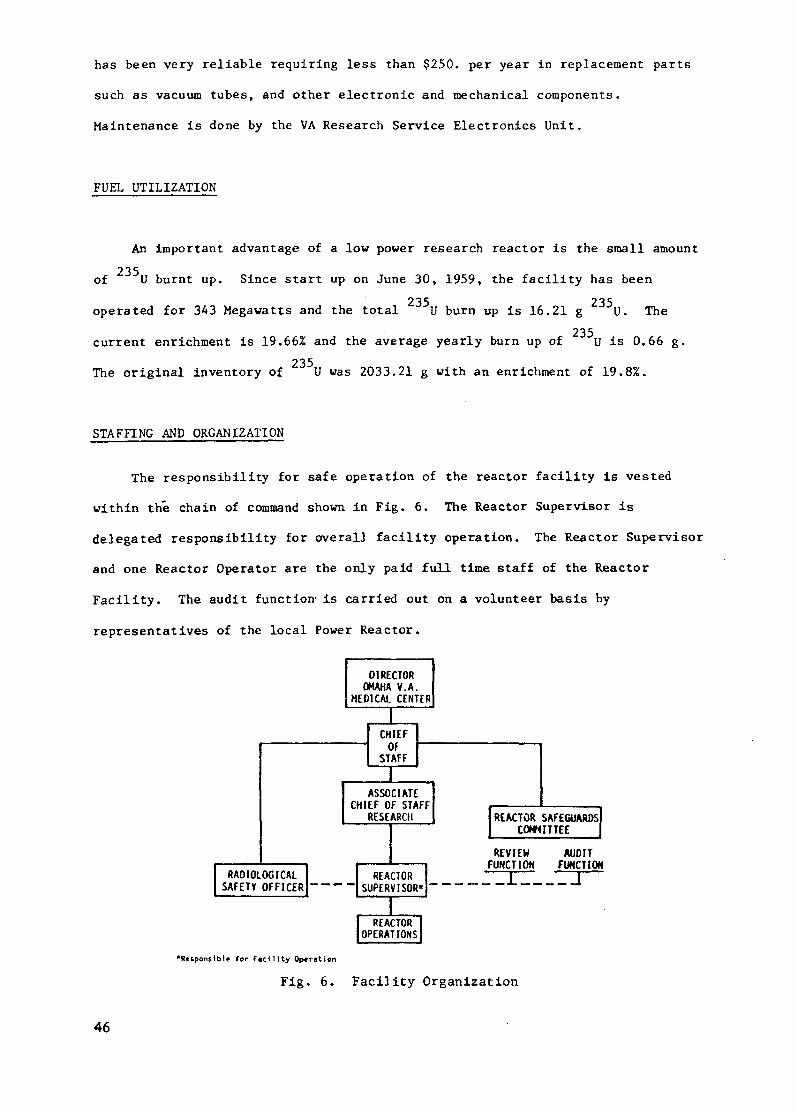
STAFFING AND ORGANIZATION
The responsibility for safe operation of the reactor facility is vested
within the chain of command shown in Fig. 6. The Reactor Supervisor is
delegated responsibility for overall facility operation. The Reactor Supervisor
and one Reactor Operator are the only paid full time staff of the Reactor
Facility. The audit function is carried out on a volunteer basis by
representatives of the local Power Reactor.
REVIEW AUDITFUNCTION FUNCTION
---_ __-Z I -- j
"Responsible for Facility Operation
Fig. 6. Facility Organization
46
UTILIZATION OF THE FACILITY
I. Training of Power Reactor Operators
Although most of the candidates for the course had either
received previous training in the Westinghouse Reactor Operator Training
Program, had operated nuclear submarine reactors or had previously operated
power reactors, they were not offered the opportunity to perform the extensive
manipulation of a reactor that a small research facility will allow.
In designing the course it was decided that for 100%
participation in each experiment by the trainees, they would be divided into two
groups of not more than five each. Each group was allotted four hours per
experiment and while one group was performing an experiment the other group was
in a class room with an instructor writing up and critiquing the previous lab
and preparing for the next experiment. It was also decided that for maximum
effectiveness, students would be allowed to write up each experiment during the
discussion period.
Table II, shows the schedule for a 10 day course given for Omaha
Public Power Company Fort Calhoun Station Operators. A course was also held for
Nebraska Public Power District Cooper Nuclear Station Operators.
Prior to the training period on the reactor, each group had an
on-site 12 week Nuclear Fundamentals Course conducted by the University of
Nebraska. Thus it was not necessary to start with basic fundamentals.
47

Table II. Power Reactor Operator Training Course
Class Schedule
Day Experiment
1 Instrumentation Familiarization andCalibration - Exp. #2
2 Unloading Fuel Exp. #1Fuel Loading Exp. #3
3 Unloading Fuel Exp. #1Fuel Loading Exp. #3
4 Reactor Shutdown andReactivity Measurements, Exp. #4
5 Approach to Critical withControl Rod & Normal Startupand Shut Down Exp. #5
6 Power Level Control and RodManipulation Exp. # 6
7 Delayed Neutron and Compensationin C1C - Exp. #7
8 Rod Calibration Exp. #8
9 Internal Reactivity ChangesExp. #9
10 Gamma Effects and ProgrammedPower Changes Exp. #10
Group A
AM ExperimentPM Discussion
AM ExperimentPM Discussion
AM DiscussionPM Experiment
AM ExperimentPM Discussion
AM ExperimentPM Discussion
AM ExperimentPM Discussion
AM ExperimentPM Discussion
AM ExperimentPM Discussion
AM ExperimentPM Discussion
AM ExperimentPM Discussion
Groups B
DiscussionExperiment
DiscussionExperiment
ExperimentDiscussion
DiscussionExperiment
DiscussionExperiment
DiscussionExperiment
DiscussionExperiment
DiscussionExperiment
DiscussionExperiment
DiscussionExperiment
Some of the highlights of the individual experiments are as
follows:
Instrumentation Familiarization and Calibration: Includes
source-detector geometry effects demonstrated by placing the Fission Counter in
a fixed position and varying the location of the neutron source.
Unloading Fuel: Fuel from the reactor is completely removed from
the core and stored in racks around the walls of the reactor tank. This
experiment demonstrates fuel handling procedures, including fuel inventory, and
radiation safety and monitoring procedures.
48

Fuel Loading: Includes the planning and execution of a fuel
loading plan for safe approach to critical and demonstrates 1/M techniques and
the importance of source-detector geometry. During the approach to critical
experiment the student is instructed to observe the reactor kinetic behavior
during subcritical operation and to note how this behavior changes as
criticality is approached.
Reactivity Measurement and Shutdown Margin: Demonstrates the
rod-drop, prompt jump, and positive period method of measuring reactivity and
provides a measurement of shutdown margin for the reactor.
Approach to Critical with Control Rod: Uses the 1/M technique
for approach to criticality using a control rod and again demonstrates reactor
kinetics.
Delayed Neutron Effect: The effect of delayed neutrons for both
positive and negative reactivity insertions are studied.
Compensation Effects on Compensated Ion Chambers: The response
of compensated ion chambers during startup and shutdown are shown for
over-compensation and under-compensation of the instruments.
Internal Reactivity Changes: The instructor simulates Xenon
buildup on a condensed time basis by inserting the regulating rod causing a
decrease in power. It is then the responsibility of the trainee to hold the
power level constant to ± 1%.
Gamma Effects: The effects of high gamma fluxes on the reactor
instrumentation is investigated.
49

Programmed Power Changes: This experiment combines the knowledge
and experience gained in earlier experiments. The trainee is given a prescribed
set of reactivity changes from which he predicts the reactor response. The
student then carries out the prescribed reactivity program and compares the
actual results with those predicted.
After presenting the course to 40 trainees it was found that
without exception the students were able to understand better the operation of a
reactor and had the opportunity to obtain answers to many questions that they
had not been able to have answered during their prior experience with reactors.
This was primarily due to the fact that by utilizing a small research reactor
they had more opportunity to manipulate the controls of the reactor and to
observe the reactor kinetics. The students were asked to bring the recorder
chart made during each of their laboratory periods to the discussion period, and
a very popular part of the course was the discussion that arose from examining
these charts. Many times the critique of the charts led to further
investigation of reactor kinetics during the next laboratory period. After the
initial training period was completed, there were unexplored possibilities for
using the research reactor as a refresher course for operators prior to
relicensing.
II. Biomedical Research
The Omaha Veterans Administration Medical Center (OVAMC) Nuclear
Reactor is utilized in four broad categories: 1) As a VA common resource; 2)
for development of procedures for determination of trace element and trace
molecule concentration in biologic systems; 3) to assess isomeric transition as
a biologic tool; and 4) for a fundamental research program. Each of these
categories will be explained in detail.
50

A. Utilization of the Nuclear Reactor as a V.A. Common Resource
The major purpose of the nuclear reactor laboratory in this
category is to serve as a common resource for the VA Medical Center
investigators in Omaha and throughout the country. Specifically, it can be
contacted as to whether trace element or trace molecular analyses related to
specific medical problems can be accomplished. If there is no literature or VA
Medical Center Reactor Laboratory procedure available, the feasibility of
developing a unique procedure will be explored with the investigator. If there
is an alternative procedure such as atomic absorption spectrometry or mass
spectrometry that can be used elsewhere to assay the samples this information
can be related to the investigator.
Neutron activation analysis (NAA) has been shown (1) to be
one of the most sensitive tools for determining trace amounts of
radioactivatable elements in biological samples. By irradiating a sample of
tissue or body fluid with reactor neutrons, concentrations of the order of parts
per billion for over 45 elements can be determined. However, in the past, the
availability of a nuclear reactor for activating samples was limited. Because
most of the reactors that would be available are large megawatt facilities and
have a high operating cost, the analyses for a large number of biological
samples has been expensive and, consequently, not very cost effective. Of the
41 biological applications papers presented at the 6th International "Modern
Trends in Activation Analysis Conference" held in Toronto, Canada, in June,
1981, only eight papers were presented by investigators from the United States
and they utilized only five separate reactors. The operating budgets of four of
the five reactors were over $120,000. per year (2) with only the Omaha VA
Medical Center reactor having an operating budget of $73,000. being less. Of
the 35 U.S. Research Reactor Facilities capable of performing neutron activation
analyses on biological samples, only seven reported an operating budget of less
than $90,000. per year (2).
51

Any analytical technique contributes to medical research
only if it can provide information to solve a specific medical problem. Quite
often activation analysis techniques are developed with no specific application
in mind at available facilities instead of answering specific medical questions.
The Omaha VA Medical Center reactor resource is unique in that it has: 1) a low
operating budget allowing samples to be irradiated on a cost-effective basis,
and 2) a research team, which includes radiochemists from the University of
Nebraska at Lincoln, biochemists, physicists, and medical investigators from
Omaha Medical Schools and outstate VA investigators. Consequently, techniques
have been developed and applied to solve specific medical problems. The Omaha
VA Medical Center has the only nuclear reactor laboratory located within a
hospital facility in the world. Having this resource adjacent to the medical
research wing further adds to the usefulness of the facility. Its record as a
common resource and its publishing record of the past 13 years demonstrates this
fact.
B. Development of Procedures for Determination of Trace
Elements and Trace Molecule Concentration in Biological Systems.
1) Elemental Analyses
In general the most widely used NAA approach for trace
element determinations, involving biological samples, as seen in the literature
has been by instrumental neutron activation analysis. However, due to the
abundance of the interferring ions sodium and chlorine in biological samples, we
sometimes find it necessary to use pre-or post-irradiation chemistry to separate
out these ions. Table III shows the methods that have been developed in our
laboratory. Precise techniques for each element can be found in the Analytical
Chemistry papers listed in the bibliography.
52

Table III. Neutron Activation Analysis Methods
ELEMENTAL NEUTRON ACTIVATION PROCEDURES
ELEMENT METHOD BRIEF PROCEDURE ANALYZED PHASE
COPPER (3) SOLV. EXT. DITHIZONE 'd' IN CCI 4 ORGANIC AS Cu 'd"
ZINC (3) SOLV. EXT. AQUEOUS LAYER OF ABOVE ORGANIC AS Zn 'dADDED TO SODIUM THIOSULFATEAND 'd' IN CCl4
MANGANESE (3) SOLV. EXT. AQUEOUS LAYER OF ABOVE ORGANIC AS Mn-ADDED TO SODIUM DIETHYL- DIETHYLDITHIOCARBAMA1DITHIOCARBAMATE AND CHCI 3
MAGNESIUM (3) SOLV. EXT. AQUEOUS LAYER OF ABOVE ORGANIC AS Mg-TTAADDED TO N-BUTYLAMINE ANDTTA IN CHCI 3
CADMIUM (4) SOLV. EXT. 'd' IN BENZENE. SODIUM ACID LAYERPOTASSIUM TARTRATE AND NHOH.ORGANIC PHASE WASHED WITHNaOH, AND H2 0 DISSOCIATEDWITH HCI, ACID PHASE PUT INTOADDITIONAL SEPARATIONFUNNEL WITH 'd' AND CCI 4
SELENIUM (5) N.D. DIALYZE AND LYOPHILIZE LIQUID LYOPHLIZED SAMPLESAMPLES. LYOPHILIZE SOLIDSAMPLES
IODINE (6) SOLV. EXT. HNO3-H 2 02 OXIDATION WITH ORGANICCCI 4 EXTRACTION
ALUMINUM (7) CATION EXCH. AGSOWX8 CATION EXCHANGE RESINRESIN. ELUTION WITH 1M HNO3
VANADIUM (8) CATION EXCH. AG5OWX8 CATION EXCHANGE ELUENTRESIN. ELUTION WITH H2 N0 3AND NH4 OH
d = DITHIZONE TTA = THENOYLTRIFLUOROACETONE
d' a DITHIZONATE EXCH. = EXCHANGE
SOLV. EXT. = SOLVENT EXTRACTION N.D. - NON DESTRUCTIVE
TE
2) Molecular Neutron Activation Analysis (MONAA)
Because of the complexity of living organisms and the
paucity of analytical techniques, it has been difficult up to now to determine
the molecular nature of trace elements in biological matrices. However, with
the increasing emphasis for information on the molecular nature of the trace
elements in biological systems and recent improvements in separation and
detection methods such as gas chromatography (GC) and high performance liquid
chromatography (LC), it is now possible to devise approaches in chemical neutron
activation analysis for trace molecule determinations. One of the most powerful
new techniques is liquid chromatography. However, it suffers in that the most
sensitive LC detectors currently available are only 1/1000 as sensitive as GC
electron capture detectors. Because of the trace amounts of molecules in
53

biological samples it is necessary to devise unique methods of combining
chromatography and neutron activation analysis in order to assay samples in the
parts per billion range.
By combining neutron activation detection with gel
filtration and high-performance liquid chromatography (LC) our laboratory has
developed a method for detecting and quantitating the iodoamino acids MIT and
DIT and the thyroid hormones T2 T3, and T4 in urine (9). Although the
procedure developed is not as simple as radioimmuno assay (RIA) it allows the
simultaneous detection of trace quantities of thyroid derivatives and offers an
alternate technique for assigning thyroid hormone assay values for various
biological systems. Except for the reported values for thyroid derivatives in
serum, there is a paucity of data for urine values. It is interesting to note
(A)T2 T3 T4
I 100. '
iO )4 18 2'2 26 SO 4
-' 0 4 8 12 16 20 24
ELUTIOM VOLUME (mL)
Fig. 7. Chromatograms of human urine (---) and human urinespiked with 1 ppm iodoamino acids and hormonal iodine ( -- ),employing neutron activation detection of I after a gel-filtration step through a Bio-Gel P-2 resin. The HPLC mobilephase is (A) water/methanol (40/60 (v/v)) + propionic acid(0.25%) and (B) water/methanol (85/15, (v/v)) + propionic
acid (0.) N.T DI
I 9° U
10 14 18 22 26 30 34ELU1ION VOLUME (mL)
Fig. 7. Chromatograms of human urine (---) and human urinespiked with 1 ppm iodoamino acids and hormonal iodine (-)employing neutron activation detection of I after a gel-filtration step through a Bio-Gel P-2 resin. The HPLC mobilephase is (A) water/methanol (40/60 (v/v)) + propionic acid(0.25%) and (B) water/methanol (85/15, (v/v)) + propionicacid (0.25%).
54

that because of the number of compounds present in urine, it is not possible to
distinguish trace quantities of the thyroid derivatives by conventional
techniques such as LC-UV (254 nm) detection. Fig. 7 shows chromatograms of the
final separation.
The next procedure developed was for the determination
of chlorinated pesticides in urine (10). While the tri-chloro bis
(p-chlorophenyl) ethane family of compounds (DDT) has been banned from use in
many countries, it is still widely used in some countries, and thus its use can
constitute a serious problem for the global population. The urinary excretion
of DDA, a metabolite of DDT, can be used as an indicator of exposure to DDT.
The most widely used technique, especially by the U.S. Environmental Protection
Agency laboratories, is GC separation employing an electron capture detector.
Unlike previous procedures, where chemical
disintegration is employed prior to GC separation our molecular neutron
activation analysis procedure involves physical separation of DDA from other
compounds by liquid chromatographic (LC) separation with subsequent neutron
38activation of the collected eluent producing Cl. Radioassay of the contents
of the irradiated vials then yields quantitative results. Chromatograms of the
procedure are shown in Fig. 8.
^ ~~56Q ODD
480.ODA DOT
o D DDE40C E 90- ---- 2/10FULL SCALE
. 2 FULL SCALE g3
| 60- URINE \ |240. l l
O Q
160.
,30 / , \
4 8 12 16 20 24 28 32 36 4 8 12 16 20ELUTION VOLUME(0.5ml) ELUTION VOLUME (0.5ml.j
Fig. 8. Chromatograms of human urine (---) and human urinespiked with 1.0 ppm of the chlorinated compounds (-) aftera solvent extraction step (on the left), employing a neutronactivation detection of 38C1 after a solvent extraction step(on the right).
55

Our most recent effort has been the development of a
method for the determination of trimethylselenonium ion (TMSe) in urine by anion
exchange - cation exchange chromatography, selectively capturing the TMSe on the
cation exchange resin (11). The TMSe fraction is irradiated with neutrons and
radioassayed for 7 7MSe activity. TMSe is an important urinary metabolite at
doses of selenite insufficient to trigger the respiratory excretion of
demethylselenide (DMSe). The procedure is very effective in isolating the TMSe
from selenocysteine and selenomethionine as can be seen in Fig. 9. The
inorganic selenium, not shown in the figure was also shown to be eluted in the
first 5 mililiters. The lower limit of detection of this method at the current
neutron flux of 3.7 x 10" n/cm2-sec is 10 ppb TMSe.
100
low -
20 40 80 120 160 200 220ELUTION VOLUE (rnL)
Fig. 9. Chromatogram of human urine spiked with 8lenium com-pounds employing neutron activation detection of Se afteran elution with 0.5 M LiNO solution through the tandem ionexchange chromatography columns.
C. The Assessment of Isomeric Transition as a Biologic Tool.
As a result of nuclear reaction, a nuclide may be left in a
high energy level (metastable nuclear state). The lifetime of the metastable
-17 -12 state is usually on the order of 10 to 10 second. However, a nucleus can
56

exist in a metastable state for a length of time long enough to be measured. A
number of isomers which have a comparatively long half-life have been found in
the last decades for example, Co-60m (10.7 min.), Br-80m (4.4h), Br-82m (6.2m)
and I-130m (9.2 min.).
De-excitation of a nucleus from its metastable state to the
ground state (isomeric transition) results in internal conversion or release of
energy in the form of gamma-ray emission. During the internal conversion
process extra-nuclear or orbital electrons may acquire enough energy to be
released from the atom. The ejected electron is called an "Auger electron".
Since the discovery of the isomers 82mBr with a half life of 6.2 minutes and
30I with a half life of 8.9. minutes it is possible to study the consequences
of the Auger effect in simple chemical systems, aqueous solutions of
biomolecules and in biological systems. The biological consequences of the
Auger effect are well documented (12,13,14,15). There are drastic chemical and
biochemical consequences associated with the Auger effect which result in double
strand breakage of the DNA molecule. Up to the present time the mechanisms
125leading to the biological damage especially by Auger isotopes such as 1I is
not well understood. The question is how applicable is the Auger effect
Coulombic explosion model to condensed phase biological systems? That is, what
is the relative importance of charge neutralization, ionization and/or
excitation by direct interaction with Auger electrons? This laboratory has been
involved for the past 20 years in the study of isomeric transition reactions of
8Br and 130mI in organic and biological systems. In order to realize the
potential of isomeric transition as a diagnostic or therapeutic tool it is
important to develop a long range program evaluating the physical and chemical
consequences of the effect in simple systems and extrapolate these results to
more complex biological systems. Already we have determined the kinetic energy
spectrums of bromine ions and iodine ions involving simple organic molecules in
the gas phase by virtue of isomeric transition Coulombic explosion for 8 2 mBr
(16) and I (17). The number of fundamental studies we have reported is too
57

numerous to indicate here. One of the important experiments we have already
completed involves the applicability of the Auger effect Coulombic explosion
model to condensed phase systems (18). We have found that the Auger effect
Coulomb explosion model has applicability to simple organic molecules such as
methyl bromide dissolved in water. It is important to realize that whether it
is for diagnostic or therapeutic purposes radioiodine labeled derivatives have
the same chemical properties as the non-radioactive pharmaceutical. On the
other hand, iodine-130m-an isomer of iodine -can undergo high energy chemical
reactions in a "test tube" releasing tremendous amounts of localized radiation
by virtue of the Auger process. This amplification effect has been reported in
the recent literature, especially involving X-ray resonance absorption of zinc
in biological systems. We are mainly interested in studying iodine reactions
activated by isomeric transitions in thyroid-related derivatives in an aqueous
medium, observing reaction selectivity not found in the usual radio-iodine
labeled reactions and in applying our results as a tool for molecular biologists
(thyroid chemical applications as a diagnostic or therapeutic tool).
Radionuclides which decay with emission of Auger electrons
produce more localized radiation damage than radionuclides which are pure beta
emitters, and much research has been done recently concerning the particular
toxicity of the Auger effect. For example, it has been found that the toxicity
of 1-125 which decays 100% by electron capture is about 5-10 times greater than
tritium (H-3), a pure beta emitter, when incorporated into DNA and thyroid
gland. So far, experiments on toxicity of the Auger effect only emphasize
empirical observations. Perhaps one of the difficulties in determining the
reaction mechanisms involved is the change in nature of the incorporated
radioisotope after decay. For example, the incorporated 1-125 decays to Xe-125
which is a stable isotope. Therefore it will be difficult to analyze the
products formed as a result of the Auger effect caused by the decay of 1-125.
However, if one can incorporate an isomer of a radioisotope into a molecule, the
58

daughter of the radioactive isomer can be easily detected since the daughter is
also a radioactive atom.
By incorporating I-130m produced by radioactive neutron
capture into a biomolecule, e.g., MIT or DIT, one could detect the products
formed as a result of the Auger effect caused by the isomeric transition of
I-130m -- 1-130. Analysis of the product distribution will allow one to obtain
some insight into the reaction mechanisms involved. Another advantage of using
I-130m is that experiments can be conducted in the absence of interfering
radiolytic effects due to the gamma-radiation in the reactor. The low-neutron
flux of a low power reactor has proved to be ideal for this work.
A better understanding of the reaction mechanisms will allow
us to obtain a more realistic evaluation regarding the question of health
physics and the potential of applying isomeric transition to biological
experimentation and medicine. Since there are a large number of radioactive
elements which are important in biology and which may decay by isomeric
transition, e.g., Co-54m (IT)--* Co-54 and Zn-69m (IT)-- Zn-69, the study of
isomeric transition of I-130m- -I-130 may serve as a model for future studies
of the isomeric transition of these atoms in other biomolecules.
D. Fundamental Research Program - Under the Direction of
Professor E.P. Rack, University of Nebraska-Lincoln, Nebraska and Reactor
Consultant.
Hot atom, high energy or "hot" chemistry, is an important
tool for basic research in areas important to energy, environment and medical
technology. "Hot" chemistry is a probe, an interactive science which embraces
many fields; from hot atom reactions in simple hydrocarbon systems to
theoretical development of high energy particle reactions. Utilizing reactive
species possessing non-Boltzmann energy distributions, high energy chemists have
59
discovered and characterized new reaction channels in organic and inorganic
systems; contributed to the theories of energetics, dynamics and systematics;
developed new techniques of chemical detection and analysis; and aided
biological and medical sciences.
High energy distributions of atoms and/or ions can be
produced via two classes of activation: chemical accelerators and bulb
techniques. Each type of experiment produces reactions that can contribute to
the characterization of high energy species. Each experimental class relates
properties unique to its technique.
Chemical accelerators impart kinetic energy to atoms, ions
or molecules by use of electromagnetic, pressure differential or ultrasonic
gradients. The particles are accelerated in a straight line (linear or
tangential, hence the name "beam" experiment) with a resultant kinetic energy
distribution of narrow bandwidth (generally a Boltzmann distribution centered
about the terminal accelerator energy). The atomic-, ionic- or molecular-beam
is produced in a near vacuum and permits the examination of atom-molecule and/or
ion-molecule single collision reactions. The data obtained reveal information
on intrinsic properties of reactions; e.g. reactive cross sections as functions
of scattering angle and energy. However, chemical accelerators are limited in
their abilities to measure endoergic reactions, to have energy resolution and
product identification simultaneously, to orient molecules (dynamics), and to
study the effect of environment (even 1 torr pressure) and multiple collisions
on reactivity.
Bulb techniques are multi-collisionally oriented. The
kinetic energy imparted to atoms or ions are the result of nuclear recoil or
photochemical recoil activation. While photochemical and some nuclear
activation modes produce atoms, ions or radicals within narrow kinetic energy
60

limits, the multi-collisional nature of the technique results in collisional
"cooling" of the "hot" entities, producing a broad spectrum of kinetic energies.
Extrinsic properties are readily measured (the hot species
or medium taken in bulk) and intrinsic properties are inferred. New reaction
channels (both exo-and endoergic) have been observed and characterized.
Although molecules cannot be oriented, the ease of product indentification
(including diastereomers and enantiomers) permits study of reaction dynamics.
The effect of the molecular environment on the reaction systems from low
pressure gas to solid state glasses and crystals is easily studied in bulb
experiments. These studies can significantly contribute to a better
understanding of the photocatalytic cage effects or de-excitation processes, an
area that may be important in photochemical energy conversion processes.
In our research work employing the bulb technique, we are
interested in the area of monovalent high-energy physical-organic chemistry,
concentrating on heavy halogens activated by radiative neutron capture.
E. Problems and Limitations Related to Low Power
The only limitation of having a low power reactor is the
lack of sensitivity in neutron activation analysis. In many cases, however,
this is balanced by being able to analyze the short half-life isotopes of the
element since the interferring ions are not activated to as great an extent
thereby keeping the dead time of the radiation detection system in a working
range.
In summary, we feel that the advantages of a low power
research reactor such as low fuel burn up, low security requirements, low
operating budget, and the necessity for less radiation safety requirements due
to the lower neutron flux far outweigh the advantages of operating a higher
power facility for training and NAA of biological specimens.
61

REFERENCES
1. Versieck, J. and Cornelis, R.: Normal Levels of Trace Elements in Human
Blood Plasma or Serum. Anal. Chim. Act. 116:217-254, 1980.
2. Burn, R.R.: Research, Training, Test and Production Reactor Directory
DOE/ER/75033-1 American Nuclear Society, 1983.
3. Hahn, K.J., Tuma, D.J. and Sullivan, J.L.: Rapid and Simple Continuous
Radiochemical Separation of Copper, Magnesium, Zinc and Manganese in
Biological Materials. Anal. Chem. 40:6, 974-976, 1968.
4. Hahn, H.K.J., Sullivan, J.L., Blotcky, A.J., et al: Radiochemical
Separation and Determination of Cadmium from Biological Materials by
Solvent Extraction. Radiochemica Acta 13:55-56, 1969.
5. Blotcky, A.J., Arsenault, L.J. and Rack, E.P.: An Optimum Procedure for
77Nthe Determination of Selenium in Biological Specimens Using 7Se Neutron
Activation. Anal. Chem. 45:7, 1056-1060, 1973.
6. Blotcky, A.J., Duven, D.M., Grauer, W.M. and Rack, E.P.: Determination of
Iodine in Urine by Neutron Activation Analysis-Application of
Szilard-Chalmers Effect. Anal. Chem. 46:7, 838-842, 1974.
7. Blotcky, A.J., Hobson, D., Leffler, J.A., Rack, E.P. and Recker, R.R.:
Determination of Trace Aluminum in Urine by Neutron Activation Analyses.
Anal. Chem. 48:7, 1084-1088, 1976.
8. Blotcky, A.J., Falcone, C., Medina, V.A., Rack, E.P. and Hobson, D.W.:
Determination of Trace-Level Vanadium in Marine Biological Samples by
Chemical Neutron Activation Analysis. Anal. Chem. 51:2, 178-182, 1977.
9. Firouzbakht, M.L., Garmestani, S.K., Rack, E.P. and Blotcky, A.J.:
Determination of Iodoamino Acids and Thyroid Hormones in a Urine Matrix by
Neutron Activation Analyses. Anal. Chem. 53:12, 1746-1750, 1981.
62

10. Opelanio, L.R., Rack, E.P., Blotcky, A.J. and Crow, F.W.: Determination
of Iodoamino Acids and Thyroid Hormones in a Urine Matrix by Neutron
Activation Analysis. Anal. Chem. 55:4, 677-681, 1983.
11. Blotcky, A.J., Hansen, G.T., Opelanio-Buecamino, L.R. and Rack, E.P.
Determination of Trimethylselenonium Ion in Urine by Molecular Activation
Analysis. Anal. Chem. (In press).
12. Deutzmann, R. and Stocklin, C.: Chemical Effects of Iodine-125 Decay in
Aqueous Solution of 5-Iodouracil Ring Fragmentation as a Consequence of the
Auger Effect. Rad. Res. 87:1, 24-36, 1981.
13. Halpern, A. and Stocklin, G.: Chemical and Biological Consequences of
Decay. Rad. and Environm. Biophys. 14:167-183, 1977.
14. Halpern, A. and Stocklin, G.: Chemical and Biological Consequences of
Decay. Rad. and Environm. Biophys. 14:257-274, 1981.
15. Keough, G. and Hofer, K.G.: Molecular Consequences of the Auger Effect:
The Fate of Iodoeoxyuridine Following Iodine-125 Decay. Rad. Res. 67:
224-234, 1976.
16. Berg, H.E., Grauer, W.M., Helton, R.W. and E.P. Rack: Gas to Liquid
to Solid Transition in Halogen Hot Atom Chemistry. II. Systematics of
Bromine Reactions Activated by Radioactive Neutron Capture and Isomeric
Transition with Halomethanes. J. Phys. Chem. 79:1327-1335, 1975.
17. Rack, E. P.: Liquid Phase Hot Atom Chemistry: At Crossroads.
Radiochimica Acta 28:221-232, 1981.
18. Opelanio-Buecamino, L.R., El-Amri, F.A., Grauer, W.M. and Rack, E.P.:
Energetic Bromine Reactions in Liquid Aqueous Solutions of Methyl Bromide.
Radio Chemica Acta (In press).
63

SLOWPOKE-2: LABORATORY REACTORFOR NEUTRON IRRADIATION
R.E. JERVISUniversity of Toronto,Toronto, Ontario,Canada
Abstract
The Slowpoke is a small pool-type nuclear reactor designed for usein universities, hospitals and research centers. The reactor has a lowcritical mass of less than lkg of HEU fuel. The AECL has recentlydeveloped LEU replacement fuel for these reactors. The reactor iscontrolled by a single Cd control rod which could cause licensingproblems in some countries. Maximum excess reactivity is limited to3.5mk. In regular use, 10,000 to 20,000 capsules can be irradiated peryear yielding 250-350,000 data points in derived results. With an annualoperating budget of US$80,000, the estimated cost per result obtained isin the order of US$0.20 - $0.40, which is much lower than mostinstrumental trace analysis methods. Examples of recent uses includearcheometry, biological sciences, chemistry, earth sciences,environmental science, medicine, metallurgy, and industrial uses. Thegreatest number of irradiations are performed at 2kW. Forth nine percentor irradiations are for less than 1 minute and 44 percent for 1-10minutes. The reactor has experienced less than one system malfunctionper 3 reactor years.
SUMMARY
SLOWPOKE is a novel new type of 5 to 50 kW hybrid pool reactor
developed by AECL, Canada and intended for use in universities, hospitals
or research institutes. The reactor is compact, reliable, 'user-friendly'
and inherently safe to operate and to use over long periods of time as a
source of neutrons at fluxes up to or slightly over 1012 cm 2-s 1. Its
design entails a number of features: lowcritical mass of fuel, high
flux-to-power ratio, provision for passive reactivity adjustment for 10-15
operating years, inherent safety through highly negative moderation temp-
erature and void coefficients, absence of conventional automatic 'scram'
devices, or need for an attending reactor operator.
The SLOWPOKE design involves a segregation of a volume of water
(0 1.5 m 3) surrounding the reactor core from the reactor pool itself by
having the reactor assembly enclosed in a reactor vessel which is installed
65

in a cylindrical pool of 7-8 metres depth (27 m3 volume). This arrangement
not only limits the circulation of any radionuclides arising from the
reactor assembly to a dedicated purification system, but it also restricts
and delays heat transport for the reactor core to the surroundings, parti-
cularly in the event of any reactor power surge. Principal reactor control
over the short-term (daily) basis is by a cadmium adjuster rod and over the
longer-term (1-15 years) by adjustments to the core reflector. Stand by
shut-down capability using Cd capsules installed manually, is provided
also.
Typically a SLOWPOKE-2 is operated for 1500-2500 h-a- 1 for a total
'nvt' of approximately 2 x 10¹⁸ per year whereas a useful reactor core
lieftime is estimated to be 3 to 3.5 x 10¹⁹ nvt before replacement. In
regular use as a neutron source, about 10,000 to 20,000 capsules containing
a wide variety of materials to be neutron-activated can be irradiated per
year, yielding as many as 250-350,000 individual data points in derived
results. Considering that typical annual reactor operating costs range
from $(U.S.) 60-80,000, the estimated unit cost per irradiation, or per
result obtained through access to SLOWPOKE, is of the order of $(U.S.) 0.20-
0.40 which is much lower than most instrumental trace analysis methods.
The operating experience gained by the combined total of 60 SLOWPOKE
reactor operating years has proved the reactor to be well-designed,
reliable (less than one system malfunction per 3 reactor years), and safe
for use in institutions which are situated in heavy-populated urban areas.
1. Introduction
A considerable number of research reactors (about 300) have been
installed in both governmental and private institutions mostly during the
past three decades. While a fraction of these were dedicated to reactor
physics, neutron and radiation physics and materials research, other reactors
were operated primarily as a local source of neutrons for (i) radioisotope
production and (ii) neutron activation of selected target materials.
66

Most pool-type research reactors which were designed to operate
at power levels of 100 kW or greater have utilized specialized enriched
U cores, duplicated safety shut-down and control systems and reactor
buildings with restricted exhaust ventilation. These features and the
attendant requirement for a sufficient number of licensed operators and
radiological safety technologists have usually entailed a reactor capital
cost for installation of $(U.S.) 5-10 million and annual operating and
maintenance costs of about $(U.S.) 1 to 1.5 million. Because of these
costs many research centres, universities or hospitals both in developed
and developing countries have considered that the installation and opera-
tion of a dedicated nuclear reactor plus associated nuclear instrumentation
was too expensive to be justified in terms of the limited extent of nuclear
physics, reactor physics, neutron or radiation research that could be
performed. It has been for such reasons of cost and staffing requirements,
among other reasons it seems, that a substantial fraction of the world's
research reactors installed by the 1950's and early 1960's have been
closed down.
On the other hand there is much useful pure and applied research
possible when sources of neutrons with fluxes greater than 1010 are
available, and the number and variety of such neutron uses continue to
expand, many of which are, potentially of importance to developing
countries. Examples of some of these beneficial and unique applications
of neutrons that have been made in Canada are cited below in this report.
It seems therefore that there is a need to find lower cost and safer
sources of neutrons to permit such research and the associated applications
to be developed. The development of alternate, low power, simple and safe
nuclear reactors can meet such needs. This report describes one such
reactor, SLOWPOKE-2, which has the advantages of low costs, safety,
compactness and suitability for installation in a regular laboratory
building without special containment or ventilation.
67
Up to the present date, a total of 11SLOWPOKE reactor installations
have been undertaken: the prototype SLOWPOKE, 7 SLOWPOKE-2 units in
universities and research laboratories, 2 in foreign countries: Jamaica
and West Germany - the latter which has not been completed for reasons for
licensing. Among these reactor units extending back to start-up in 1970,
there has now been accumulated a total of about 60-65 reactor operating
years' experience on which to base assessments of reactor reliability and
safety as well as estimates of capital and operating costs.
2. SLOWPOKE Reactor Specifications
SLOWPOKE-2 is a small pool type nuclear reactor using fully enriched
uranium fuel, water moderator and beryllium reflector. Operation is at a
thermal flux of
0.5 x 10¹¹ - 1 x 101 2 n-cm 2 s1
It is designed for use in universities, hospitals and research centres for
activation analysis and isotope production. Access to the neutron flux
is by "rabbit" irradiation tubes.
The reactor is housed in a closed container suspended in a water
pool. This restricts access to the core and provides for limited and con-
trolled release of fission products.
A negative temperature coefficient and low excess reactivity make
the reactor inherently safe. Conventional electro-mechanical safety devices
are unnecessary and a full-time operator is not required.
A SLOWPOKE-2 installation comprises five major components, each
with a distinct fuction. These are the reactor, the pool, the control
console and the irradiation and service systems.
2.1 Reactor
The reactor (figures 1, 2, and 3) consists of the core, beryllium
reflectors, control rod and drive, neutron detector, thermocouple, five
68

Figure 1. A SLOWPOKE Installation
kJ-r.
c
,, ,,,,, ........... ... ., , .. ffl
.l!|I th ttt8 .7~~~~~~~~~~~-^ i;:;::;::-:~~~~~:::
""'·:' ·ii·I :,�·-- · :i·'�': I:i. c�t`
�'' 2·i·;LI··-'
·;:·· i-
:1. ;.·::;::' 51:i· 22-·
.··· ··�--;�.� '·"··: sr, "'·' · �·'
COOLANT FLOW BY NATURAL CONVECTION
Figure 2. Critical Assembly & Reactor Container
69

small (inner) irradiation tubes, five large (outer) irradiation tubes and
the reactor container.
Figure 2 is a cut-away view of the critical assembly, mounted in
the reactor container lower section.
The core comprises the fuel cage and fuel elements. The cage is a
spool-shaped assembly of aluminum alloy with space for up to 342 fuel
elements. The control rod moves within its central spindle. The fuel
elements are 2 3 5U enriched uranium-aluminum alloy, extrusion clad with
aluminum.
The core sits within the annular beryllium reflector, resting on
the lower beryllium reflector. The lower reflector and beryllium annulus
are spaced to form the lower orifice, which controls water flow through
the core. The critical assembly top plate and annulus are spaced to form
the upper orifice. The shim tray holds the upper reflector which consists
of semi-circular beryllium shims. Shims are added approximately once per
year to compensate for fuel burn-up and poisoning.
The reactor is cooled by natural convection (figure 2). Water
enters the core through the lower orifice, rises through the fuel elements,
and leaves the core via the upper orifice. It then sinks within the
reactor container, transferring heat through the container wall to the pool
water.
The control rod is a cadmium tube encased in aluminum. It moves in
the centre of the fuel cage, guided by a tube in the shim tray. The control
rod is suspended by cable from a single turn drum, mounted on the reactor
top plate (figure 3). The drum is driven by a bidirectional AC synchronous
motor. Control rod travel is normally limited by electrical microswitches
in the drive mechanism, but if these should fail mechanical stops on the
drum will limit travel. The rod position potentiometer is incorporated in
the drive assembly.
70

IRRADIAON TUBERETURN AIR UNE
CONTROL RODDRE MECHANISM IRRADIATION TUBE
CONTROL ROD
Figure 3. Reactor Control Mechanism and Mounting Assembly
There are ten irradiation sites. Five inner irradiation tubes are
installed in equispaced holes within the beryllium annulus and five outer
irradiation tubes are installed outside the beryllium annulus.
Reactor instrumentation comprises one thermocouple, located in the
upper orifice and one flux detector, located in a hole in the beryllium
annulus.
The reactor container provides support, location and containment
for all reactor components. It is suspended from two steel "I" beams
placed across the pool. The container is built in two parts. The lower
part contains the critical assembly. It can be separated under water from
the tubular section, thus enabling either the core or the entire critical
assembly to be manipulated while completely under water.
2.2 Control Console
The control console contains the reactor control system, the
radiation monitoring system readouts and a service panel monitoring the
auxiliary systems.
The control system causes the control rod to move in response either
to a changing flux detector signal (automatic control) or to a manual
command (manual control).
71

Flux monitoring is by a self-powered cadmium neutron flux detector
located in a vertical hole in the beryllium annulus.
In the event of a failure of the electrical power line all systems
will cease to operate, except temperature recording and radiation monitoring
which switch automatically to an auxiliary power system. Auxiliary power
is derived from lead acid batteries. During normal operating the batteries
are continuously charged. Battery voltage is indicated by a meter on the
service panel (figure 4). The auxiliary power ON light on the service
panel is illuminated during operation of the auxiliary system. The
operator is informed of a temporary line failure that occurred during
his absence by the MEMORY light.
~ SEE 1 Em t» a a u j 0 0 0 Mo
Figure 4. Control Console
2.3 Service Systems
These systems are for water purification and level monitoring,
cooling and gas purging.
The pool water and reactor water are maintained at specified purity
levels by separate water treatment plants. Separate plants are used to
ensure that there is no mixing of pool and reactor water.
The reactor water plant contains a mixed bed deionizer. This bed
is replaced when depleted. Reactor water level is maintained by manually
adding deionized water through the purification plant.
72

Both treatment plants incorporate flow and conductivity meter.
The pool is cooled by city water flowing through a simple panel
heat exchanger. This water is discharged to the site drain. At no time
does it come into contact with either the reactor or pool water. Water
flow is controlled by a manual valve and flow meter. A light on the service
panel is illuminated when cooling is on.
There is a very slow build up of hydrogen in the reactor container
head space from radiolytic decomposition. This is purged once per week by
blowing air through the head space. The purge air is taken from the
building supply, filtered and then passed through a timing valve and flow
meter into the reactor. It exhausts through a filter to atmosphere.
2.4 Irradiation Systems
SLOWPOKE-2 will accept ten irradiation systems, each comprising an
irradiation tube (the part within the reactor container) and capsule
transfer system.
The five inner irradiation tubes and the five outer irradiation
tubes are included in the basic reactor package.
Three cadmium capsules are provided with the reactor to act as
auxiliary reactor shut-down devices. If the reactor is installed with less
than three small (inner) capsule transfer systems, simple closed loops
are connected to the irradiation tubes.
2.5 Reactor Core Details
Thermal power at 1 x 10¹² n-cm-2 s- 1 - 20 kW
Fuel element positions - 342
Core dimensions diameter - 22 cm (8.66 in)
height - 22.6 cm (8.91 in)
volume - 8580 cm3 (0.30 ft3)
Water volume in core - 6940 cm3 (0.245 ft3)
73

Mean core waterSteady state Water temperature temperature above pooltemperatures rise through core temp.
(°C) ( 0C)
1.0 x 10¹¹ n.cm-2 s-1 4 3
2.5 x 10¹¹ n'cm T2 s~1 7 6
5.0 x 10¹¹ n-cmM 2 sl1 12 10
1.0 x 10¹² n-cm-2 s- 1 19 17
Critical mass of 23sU - 828-898 g
Fuel life - 3.2 x 10¹⁹ nvt (10 yrs at 1 x 10¹¹ n'cm- 2 s- 1)
Fuel elements, number - 300-325
Reflectors (beryllium)
Annulus internal diameter - 22.10 cm (8.70 in)
outside diameter - 42.47 cm (16.72 in)
height - 22.75 cm (8.96 in)
Bottom plate - thickness - 10.16 cm (4 in)
diameter - 32.23 cm (12.69 in)
Top shims - diameter - 24.31 cm (9.50 in)
thickness (each) - 1.27, 0.64, 0.32, 0.16 cm (0.5,
0.25, 0.125, 0.062 in)
maximum total thickness - 10.16 cm (4 in)
Reactor Container
Diameter - outside - 0.610 m (24 in)
Length - overall - 5.270 m (17.29 ft)
lower section - 0.829 m (2.72 ft)
Length - upper section - 4.445 m (14.58 ft)
Wall thickness - 0.953 cm (0.375 in)
Flanges - ends - 0.762 m (30 in) diameter
support - 0.806 m (31.75 in) square
Material - 5052 aluminum
74

Water - level - As pool water
volume - 1.38 m3 (49 ft3)
conductivity < 1 pmho/cm
2.6 Pool
Inside diameter - 2.5 m (8.2 ft)
Depth below grade - 6.10 m (20 ft)
Depth of water above core - 4.42 m (14.5 ft)
Depth of water surface below floor - 0.9 m (3 ft)
Water
volume - 27 m3 (950 ft3)
conductivity - < 10 pmho/cm
2.7 Control Console
Control System
Control rod (cadmium) diameter - 0.40 cm (0.16 in)
Control rod (cadmium) length - 25.4 cm (10 in)
Control rod travel - 20.3 cm (8 in)
Control rod speed (60 Hz line power) - 1.06 cm/s (0.42 in/s)
Control rod time for full travel (60 Hz line power) - 19 s
Neutron flux detector type - Self powered cadmium detector
Neutron flux - operating range - 0.5 x 10 l - 1 x 10¹² ncm 2 s 1
Neutron flux - meter range - 0 - 1.5 x 10¹² n-cm 2 s 1
recorder range 0 - 1.5 x 10¹¹, 3.75 x 10¹¹, 7.5 x 10¹¹
and 1.5 x 10¹² n-cm- 2 s- 1
Temperature recorder range - 0 - 150°C
Thermocouple type - Iron-Constantan (ISA type J)
Recorder chart speeds - neutron flux - 2.54 cm/min (1 in/min) and
2.54 cm/h (1 in/h)
temperature - 2.54 cm/h (1 in/h)
75

Radiation Monitors
Number - 3
Reactor room - low level alarm - dependent on installation
high level alarm - dependent on installation
Reactor deionizer - indicating only
Type (typical) - Victoreen Model 855 Series G-M gamma monitoring
systems
display - single logarithmic scale
range - 0.01 mR/h - 1 R/h
energy dependence - ± 15% from 0.1 to 2.5 MeV
directional dependence - < 30%
accuracy - better than 20%
Auxiliary Power Systems
Output - 115 Vac, 18 Vdc
Running time - 24 h
Maximum charging current - 5 A
Batteries - type - lead acid automotive
capacity - one - 12 V, 90 Ah
two - 6 V, 90 Ah
2.8 Service Systems
Water Purification and Level Control
Reactor Container Pool
Deionizer
Conductivitymeter range 0.05-3 pmho/cm 0-300 umho/cm
Flow rate 7.5 L/m 19.1 L/m(2 USGPM) (5 USGPM)
Working 3.5 kg/cm2 3.5 kg/cm2
pressure (100 psig) (100 psig)
Water level
deviationwarnings ± 5 cm (2 in) ± 5 cm (2 in)
76

Cooling System
Cooling water flow rate - 22 L/m (6 USGPM)
Cooling water temprature rise at 2.5 x 10¹¹ n.cm- 2 s- 1 - 3°C
Pool water temperature at 2.5 x 10¹¹ n-cm- 2 s- 1, with coolingwater flow of 6 USGPM at 15°C inlet temperature - 24°C
Gas Purge System
Flow rate - 11 L/s (24 SCFM)
Purge time - 1 min
2.9 Irradiation Systems
Large (Outer): Small (Inner) site thermal neutron flux ratio(typical) - 0.5
Small (Inner) System
Capsule type - polyethylene vial
diameter - 1.58 cm (0.625 in)
length - 5.4 cm (2.125 in)
volume - 7 cc (0.43 in3)
Total daily operation - 9 x 10¹⁵ nvt
e.g. - 24 hr at 1.0 x 10¹¹ n cm 2 s- 1
or - 10 hr at 2.5 x 10¹¹ n-cm 2 s- l1
or - 5 hr at 5.0 x 10¹¹ n-cm 2 s-1
or - 2.5 hr at 1.0 x 10¹² n-cm-2 s 1
Flux uniformity (typical) - vertical - + 2.6%
horizontal - + 1%
Large (Outer) System
Capsule Type - polyethylene vial
Diameter - 2.9 cm (1.125 in)
Length - 5.4 cm (2.125 in)
Volume - 27 cc (1.65 in3)
77

Total daily operation (Typical) - 5.2 x 101 5 nvt
e.g. - 24 hr at 0.5 x 10¹¹ n.cm- 2 s~ 1
or - 10 hr at 1.2 x 10¹¹ n-cm-2 s- 1
or - 5 hr at 2.5 x 101 1 n.cm 2 s-1
or - 2.5 hr at 5 x 10¹¹ nrcm- 2 s- 1
Flux uniformity (Typical) - vertical - ± 0.7%
horizontal - ± 6%
Irradiation Controller
Time range - standard - 0.1
optional - 0.1
- 999.9 min
- 999.9 h
2.10 Operating Balance Conditions
(1) Cooling system maintains daily start-up temperature at 20°C.
(2) 9 x 10¹⁵ nvt/day operation.
(3) Maximum excess reactivity in clean cold system
iately following reactivity adjustment by shim
to 3.4 mk. A nominal value of 3 mK is used in
table.
Neutron flux (n.cm-2 s-1) 1.0x10 1 1 2.5x10¹¹
Temperature and xenon loadat daily shutdown (mk) 0.8 0.9
0.8 0.92 35U burn up and '4 9Smpoisoning (mk) 0.8 0.8
Maximum capsule load (mk)a 2.2 2.1
Minimum capcule load (mk)b 1.4 1.3
(i.e., immed-
ing) is + 2.9
the following
5x10 11 1 .0x101 2
1.31.3
0.8
1.7
0.9
2.02.0
0.8
1.0
0.2
(a) At daily shut-down following compensation for 23SU burn upand l49Sm poisoning by beryllium shim addition.
(b) At daily shut-down immediately prior to beryllium shimaddition.
78

Long Term Changes
Reactivity Loss Due to235U Burn-up and 149Sm Poisoning
1.OxlO9 nvt
0.16
0.315
0.63
1.26
1.89
2.52
3.15
Years at1011 n.cm-2 s-1
Continuous
0.5
1.0
2.0
4.0
6.0
8.0
10.0
235 U
Burn-up(mk)
0.2
0.4
0.8
1.5
2.3
3.0
3.8
149Sm
(mk)
0.7
1.4
2.5
4.1
5.1
5.8
6.2
ReactivityLoss (mk)CumulativeTotal
0.9
1.8
3.3
5.6
7.4
8.8
10.0
Reactivity Control
Control rod - regulation - 3.0 mk
shut-down - 2.1 mk
Total worth - 5.1 mk
Control rod - speed - 1.06 cm/s (0.42 in)
Control rod - rate (average) - 0.21 mk/s
Cd capsule in inner radiation sites
dropped into empty site = -1.8 mk/capsule
dropped on top of sample capsule in site - -1.3 mk/capsule
Core emperature coefficient at 25°C = -0.07 mk/°C
2.11 Building Services
Electrical, 3 circuits, each - 115 Vac, 60 Hz, 15 A
Note: Equipment can be matched to other voltages and 50 Hz.
Water - 23 L/m (6 USGPM) city water outlet. For effective pool
cooling, temperature must not exceed 15°C.
Drain - Aid resistant drain to sewer.
79

Compressed Air - Minimum pressure 5.6 kg/cm2 (80 lb/in2) at
2830 L/m (100 SCFM). Requirement in intermittent.
Maximum is 710 L (25 SCF) in any 1 minute period.
Typical continuous average is 142 L/m (5 SCFM).
Vent - Pipe to outside of building above roof level. Maximum back
pressure at 2830 L/m (100 SCFM) to be 0.07 kg/cm2 (1 lb/in2 ).
3. Reactor Operation and Performance
The first 8 SLOWPOKE-2 reactors (and the original prototype) were
fuelled with highly enriched uranium in the form of 28% alloy with Al,
clad in Al. Although small reactor cores in light water are prone to
more neutron loss by absorption and leakage, the use of beryllium neutron
reflector in SLOWPOKE results in a requirement of approximately 800-900 g
U-235 for criticality, which is not much larger than the theoretical
minimum and, compared to some other reactor designs, this small critical
mass results in saving of initial fuel costs and replacement costs. Newer
SLOWPOKE-2 reactors use a re-designed fuel core with less than 20% U-235
enrichment which is in the category exempt from requirements for inter-
national inventory inspection.
Further, the small fuel core (approximately 25 cm x 22 cm diameter)
and the relatively thick Be reflector (20 cm) produce a relatively high
useful neutron flux for applications of 1012 cm 2 s 1 in the irradiation
sites in the reflector even at the low thermal power of 20 kW.
(Fuel and moderator temperature elevations are modest at 20 kW, and
although this is currently the licensed power maximum, it has been demon-
strated that operation at 50-60 kW is feasible, with or without enhanced
coolant flow - providing fluxes of 3 x 10¹².) This high flux-to-power
ratio results in low uranium consumption and fission product production
for a given time-integrated flux, leading toa useful fuel core lifetime
(approximately 10-15 years with extensive reactor operation of 2500-3000
80

h.y 1) which is considerably extended relative to most reactors with larger
cores. This infrequent fuel core replacement, together with the small
critical mass of uranium makes the fuelling cost of SLOWPOKE-2 quite low
(see section below on costs). Although the small volume limits the access
to high flux regions for neutron uses, the available 10 irradiation sites
each capable of loading with 2 capsules, have proved more than adequate.
SLOWPOKE-2 is characterized by a negative temperature coefficient
of reactivity and negative void coefficient. Although the reactivity
change due to a rise in reflector temperature is positive, the large reac-
tivity change cause by a rise in core temperature is much larger and
produces a net negative reactivity change. This produces an inherent
safety feature, a self-regulation of excess reactivity when combined with
design-limited restriction of coolant flow to the core by size of coolant
inlet orifices and limits power levels and fuel temperature to safe values
during any power transients no matter how they are caused. Due to this
self-limiting mode of reactor-behaviour, and in view of licensing restric-
tions of maximum excess reactivity, the usual automatic safety (shut-down)
systems are not needed, and it has been judged by Canadian licensing
authorities that SLOWPOKE can be left to operate unattended.
The two excess reactivity-consuming factors are (i) increase in
moderator temperature with time of operation and (ii) buildup of Xe-135
poison. On a daily basis, the control rod having a reactivity worth of
about 3 mk is withdrawn to compensate for poison and temperature effects.
Long term reactivity adjustment is accomplished by adding a Be shim plate
to the top reflector occasionally (approximately each 12 months of operation).
Automatic limitation of reactor power excursions occurs even if
there is a loss of regulation such as, for example, the control rod cannot
be re-inserted into the reactor core after start up for mechanical reasons
or loss of drive action (in an electrical failure mode). In such an event,
the reactor power increases above the normal maximum operating power of 20 kW.
81
Although the core continues to be cooled by the normal ('un-pumped')
convective flow of water upwards through the core, the temperature of the
water in the core eventually becomes elevated to the point (approximately
40-50°C increase) when the corresponding reactivity loss cancels the effect
of the withdrawn Cd control rod. Thus, the reactor power is limited by
intrinsic reactor behaviour independent of operator intervention or
external control mechanism such as a duplicated 'scram' system.
Within these design limitations, SLOWPOKE-2 reactors operate
indefinitely at 5 kW, greater than 10 h at 10 kW and up to 1.5 h at 20 kW
before temperature increases in the moderator begin to limit continued
operation. Because experience has shown that the earlier designs and
licenced reactivity limits were quite conservative, some research has been
done on the safety implications of (i) permitting greater excess reactivity
during fuelling and 'shimming' and (ii) deployment of chilled water
injectors adjacent to the core coolant flow orifices. A 15 kW chiller
unit has been installed at the Toronto SLOWPOKE and it has been demonstrated
that much extended 20 kW operation or operation at power levels (and
fluxes) greater than 20 kW can readily be achieved with acceptable reduction
in inherent reactor safety and no physical alternations in reactor or fuel
design. Thatis, such a unit retro-fitted to an existing SLOWPOKE-2
reactor can offer these extensions in operational modes, viz. to higher
fluxes for longer periods.
Current SLOWPOKE reactors operate with remarkable reliability for
up to 2000 h per year at power levels ranging from 5 to 20 kW. Reactor
start-up is automatic, is accomplished with 100-200 seconds after certain
routine system checks, and subsequent operation for up to 72 hours do
not require direct operator supervision (however, licensing requires a
minimum of remote surveillance of power level from time to time). Failure
to operate owing to electronic or mechanical faults of reactor components
have been encountered quite infrequently, typically once per 3 reactor
operating years.
82

4. SLOWPOKE Utilization
Examples of some recent (1983-85) SLOWPOKE uses in a variety of
disciplines are: archeometry - provenance studies of ceramic fragments
from Iran, Yemeni, Yugoslavia, Greece, China, NWT, Egypt; biological
sciences - ion transport across cell walls, composition of bird (eagle)
feathers, fish subjected to acidic precipitation, Mn in fish eggs, Al
uptake by plants, effects of heavy metal deposition from acid rain on
vegetation; chemistry (pure and applied) - composition of coordination
compounds, trace copper instrumental analysis, composition analysis of
LaNi hydrogen-storage alloys, heavy metal ion absorption on synthetic and
natural absorbers, Ba and K content of video-display glasses,
new zeolite and rhodium catalysts, standard reference method for As in
biological materials; earth sciences - platinum metals in Cu-rich ores, and
in G and H chromate seams, rare earths in Felsic Volcanics, in Jimberlana
Intrusion (Australia), Bushveld Complex (So, Africa), in Archaen Volcanic
Rocks (E. Canada), development of chemical separations for Re-Os, Lu/Hf
ratios in zircons, nuclear-track age determination; environmental sciences -
trace impurities in 3 Chinese environmental reference standards, in Chinese
and Canadian coals and their combustion products, analysis of uranium
tailings, comparison of sediments from Yangtze and Don Rivers (China and
Canada), airborne particulate matter, mobile street dusts, toxicity of
industrial fly-ash; medicine - tissue Se in infants and children, bone
fluoride determination in rats and in clinical research, effects of
proctasyclin on blood flow, measurement of body water compartments, trace
elements in cystic fibrosis patients, in welding workers, steel plant
workers, rare-earth workers; metallurgy - segregation of impurities in
continuously-cast steel billets, recovery of U and Th from C1 and sulphate
leach liquors, milling of Al dross, Cu in hydrometallurgy, effect of Mn on
Si control in blast furnaces; industrial uses - trace elements in fossil
fuels, in plastics and polymers, in phosphate furnace deposits and slags,
in analytical standards.
83

Many (a 90%) of the above uses involve neutron activation of
selected samples followed by instrumental gamma spectrometry involving
(typically) 20-40 radionuclides of short (0.8 s to 25 min half-lives) and
intermediate (38 min to 30 day half-lives) and required mostly 1 to 2 minute
irradiation times. A smaller fraction required 16-18 hour irradiation
periods and were measured up to 2 weeks later for longer-lived nuclides.
Other applications made use of radioisotope tracers of half-lives
too short to be prepared at commercial reactors, but sufficiently long to
permit their safe utilization in tracer research in a variety of university
and hospital laboratories, e.g., Ba-139 (85 min), Mn-56 (2.6 h), Na-24
(15 h), K-42 (13 h), As-76 (27 h) and Hg-197 (65 h).
These uses involved about 70 professors and their research associates
and fellows (64), post graduate students (61), undergraduate research
students (44), and more than 300 other students performing assigned lab-
oratory procedures utilizing SLOWPOKE. It can be estimated that the
15,135 sample irradiations performed during 2636 operating hours (1983-84)
produced an estimated 200,000 individual measurements, many of which could
not be performed otherwise. On the basis of SLOWPOKE annual costs (see
below) it can be estimated that the unit costs for irradiations is $4-6 per
capsule irradiation or $0.20-0.50 per individual measured result. These
are costs substantially lower than most instrumental trace analysis methods
and the multielement analytical results obtained are often superior in
accuracy and concentration sensitivity.
SLOWPOKE Cost Estimates
The costs of installing, operating and maintaining a SLOWPOKE-2
reactor facility (in 1985 dollars) are given by category as follows:
SLOWPOKE Installation: (Capital)
Reactor + operating and safety systems: $800,000
Optional systems: $75,000(additional sample lines, cyclic system, core chiller)
84

Nuclear Instrumentation (for users): $100,000
Enclosure (reactor pool, room, associates labs): $500,000 (new building)75,000 (install in
existinglaboratory)
SLOWPOKE Operating: (annual)
Part-time operator: $25,000
Supplies & services: $10,000
Fuel costs (est.): $50,000 (depending on source of fuel)
SLOWPOKE Maintenance:
Reactor adjustments: $2,500
Instrumentation maintenance: $10,000
Utilization and Maintenance Detail
Further details of the operating experience, reactor performance
and program of utilization of the 8 currently operating SLOWPOKE-2 reactors
can be obtained by consulting the annual SLOWPOKE reports, contacting the
reactor supervisor, or referring to published papers from: AECL Radiochem.
Co., Ottawa; University of Alberta, Edmonton; Dalhousie University,
Halifax; L'Ecole Polytechnique, Montreal; Royal Military College (and
Queen's University), Kingston; Saskatchewan Research Council, Saskatoon;
University of Toronto; University of the West Indies (Jamaica).
85

Table 1
1983-84 SLOWPOKE Operating Statistics
Total Primary PrimaryOper. Oper. llours/ No. of Irrads./ Research Student Irrad. Irrad. Irrads./ Primary Energy
Month Days Hours Day Irrads. Day Irrads. Irrads. Hours Hours Day Use X (kWh)
July 20 225 11.3 1352 68 1352 - 658 175 8.7 77 1291
Aug. 23 226 9.8 1491 65 1486 5 578 176 7.6 78 1460
Sept. 22 246 11.2 1313 60 1232 81 1076 198 9.0 81 1263
Oct. 22 230 10.5 1526 69 1396 130 1069 205 9.3 89 1187
Nov. 22 241 10.9 1467 67 1195 272 906 189 8.6 78 1264
Dec. 17 134 7.9 848 50 814 34 393 115 6.8 86 917
Jan. 22 213 9.7 826 38 651 175 1068 184 8.4 87 1250
Feb. 21 213 10.1 1248 59 849 . 399 1049 178 8.5 84 1339
March 22 243 11.0 1771 81 1078 693 1342 209 9.5 86 1556
April 20 222 11.1 1236 62 1116 120 859 182 .9.1 82 1278
May 22 208 9.4 890 40 859 31 706 172 7.8 83 1117
June 21 235 11.2 1167 56 1167 - 994 176 8.4 75 1323
Total 254 2636 15135 13195 1940 10698 2159 15245
Av./Month 21 220 10.4 1261 60 1100 892 180 8.5 82 1270
Table 2
Distribution of Irradiations by Power
Power (kW)
Month
July
August
September
October
November
December
January
February
March
April
May
June
Total
z
< 0.2 1 2 5 10 20
4
188
704
632
696
776
784
188
216
384
412
181
247
502
89
145
239
222
143
260
183
286
333
205
130
140
150
283
63
304
36
129
118
157
365
183
67
237
409
431
315
220
316
271
309
421
511
295
212
288
150
372
-234
4 944
_- 6
5722
38
2375
16
2092
14
3998
26
86

Table 3
Distribution of Irradiations by Time
Month Time
10-60 m< 1 m 1-10 m 1-8 h > 8 h
July
August
September
October
November
December
January
February
March
April
May
June
Total
%
771
751
666
785
760
193
378
489
842
766
557
521
527
680
548
629
602
606
353
679
777
404
263
556
9
29
33
39
55
28
32
15
73
14
29
32
4
13
1
3
39
31
62
60
50
20
63
62
79
52
41
58
7485
49
6624
44
388
3
21 617
4
Table 4
Utilization Distribution History
Undergraduate
Graduate
Faculty
Non U. of T.
July 1983-June 1984 *Irrads. Hours Used
1940 1801 (17X)
4157 2422 (23%)
5870 4974 (46%)
3168 1500 (14%)
15135 10697
July 1982-June 1983Irrads. Hours Used
1799 1564 (19%)
3435 2083 (25%)
5303 3129 (38%)
2450 1469 (18%)
July 1981-June 1982 Irrads. Hours Used
1854 1501 (12%)
6514 6317 (52Z)
5648 3680 (30%)
2796 664 (6%)
12987 8245 16812 12162
* Irradiation hours.
87

- Bibliography
"SLOWPOKE: A New Low-Cost Laboratory Reactor", R.E. Kay, P.D. Stevens-Guille, J.W. Hilborn, R.E. Jervis, Internat. J. of Applied Radn. andIsotopes, 24, 509 (1973).
"Description and Safety Analysis for the SLOWPOKE-2 Reactor", M.E. Wiseand R.E. Kay, CPR-26, Atomic Energy of Canada Ltd. (1976).
"Specifications, SLOWPOKE-2 Reactor", IND-64, AECL (1976).
"The Self-Limiting Power Excursion Behaviour of the SLOWPOKE Reactor:Results of Experiments and Qualitative Explanation", AECL-4770 (1976).
"Laboratory Neutrons - a Breakthrough in Non-Nuclear Disciplines", R.E.Jervis, Inst. Physics Conf. Series No. 64, Section 7, 457 (1983).
"University of Toronto SLOWPOKE Reactor Facility - Annual Report, Sept.1984", R.G.V. Hancock and J.S. Hewitt, University of Toronto, Canada.
"An Analytical and Experimental Study of Direct Container Cooling in theSLOWPOKE-2 Nuclear Reactor", A.F. Oliva (with Professor J.S. Hewitt),M.A.Sc. Thesis, Department of Chemical Engineering, University of Toronto(1981).
88

THE MNSR REACTOR
ZHOU YONGMAOInstitute of Atomic Energy,Beijing, China
Abstract
This tank-in-pool reactor is based on the same design concept as theCanadian Slowpoke. The core is a right circular cylinder, 24 cm diameterby 25 cm long, containing 411 fuel pin positions. The pins areHEU-Aluminum alloy, 0.5 cm in diameter. Critical mass is about 900 g.The reactor has a single cadmium control rod. The back-up shutdownsystem is the insertion of a cadmium capsule in a core position. Excessreactivity is limited to 3.5mk. In both the MNSR and Slowpoke, theinsertion of the maximum excess reactivity results in a power transcientlimited by the coolant/moderator temperature to safe values, independentof any operator action. This reactor is used primarily in training andneutron activation analysis. Up to 64 elements have been analyzed in agreat variety of different disciplines.
Surmmry
In utilizing the existing larger and medium research
reactors, in order to match to the reqirement of economic
development in districts or department, the Miniature Neutron
Source Reactor (MNSIR) has been designed and developed completely
in 1984. The reactor is equipped with ten irradiation facilities
for elements quantitative analysis of products and materials. The
reactor particularly suites for multielement trace analysis of
organisms body fluid and environmental samples. The thermal
neutron flux in irradiation sites is 1 x 10¹²n/cm2 .s. Amount
of samples analized is up to tens per day. The volume of the
reactor core is 11 litre. Loading of highly enriched U-235 is
less than 1 kg. The core lifetime is about ten years, so frequent
refuelling may be avoided. The reactor possesses inherent safety,
without danger of runaway, and nuclear contamination would not
be bring about. In operating, the radiation dose rate of working
area is more lower than the level permited. Outside reactor build-
ing, the radiation level is low as natural, so the reactor can
be installed in city without misgiving. Fission heat is removed
from core by natural convention. The reactor is simple in struc-
ture, convenient for operating. Analysts would be concurrently
operator, and in establishment of staff personnel, the special
operators would not be necessary. Moreover consumption of U-235
89
is only several mg per day, the operation expenses of the reactor
is the lowest in the practical research reactors, and the construc-
tion cost is about three or four times less than ordinary Triga
type reactor, or about ten times less than medium swimming-pool
reactor.
During a year, the reactor has beon started up for 238 times,
total evergy generated has estimated about 6550kw-hr. The reactor
has exhibited excellent performance and operation stability.
1397 different s:upples have been analyzed. 64 kinds of stable
elements have been detected quantitatively, includirg F, which
half-life is 11.03 second; and Co, which half-il'e is 5.26 years.
We have carried out an unattended operating system for over-
night irradiation, a'it have realised to control the reactor by a
computer.
At present, we .ire developing commercial reactor with more
excellent performance.
THTE iNS'R REACTOR
By 1984 there have been several medium and larger research
reactors in China, including heavy water reactor, swimming-
pool reactor, and tank type High Flux Engineering Test Reactor
(HFETR). Their power is from 2000kW up to 125MW. The industry
and technique developed and accumulated in these reactors
have played an important role in developing the subsequent
research reactors in our country.
With respect to neutron activation analysis these reactors
are expensive in operation costs, lower operating availability,
and its location far from economical developed districts, so
many users hope that they would rather have own minature
nuclear facilities than send the samples to existing reactor.
For these reasons since 1980 the Miniature Neutron Source
reactor (MNSR) has been developed. The prototype reactor is
located in Institute of Atomic Energy in Beijing. It is designed
for neutron activation analysis, short-lived isotope production
and as a teaching and training facility.
The practice of HFETR showed that the high-enriched uranium
and light water core surrounded by sufficiently thick metallic
beryllium reflectors exhibited a low critical mass. applied this
experience, the MNSR uses 90% concentration uranium aluminum
90

:O.oo ItL2t}I
driving cchanJ
control rod
.1I^ M 1'
\\ I~~L~~h~a~~eL-~ ~
-0.5ot 05 \\-1 i�"
_. 1\- ' . M . .. . -1'~;
-
inlet temperaturedetctor
outlet temperature detector
,lainr irradiationtube0outer lrradatliontube
* e ucontrol lrod
. ..
- bt top berylliu
supporter
Eo.er ectlon ozr
r.eatr- '.0' ----- -
^:··'* -
- r " *'K . .o\" *** 0 P -< **\.
ism of
ateel angle frame
upper Section -A
4'ide tube of
nc . {utrouln iluxor
^^^":^^^^^ t ^ :̂ ^~~~~~~~
- .50-
THE MNSR REACTOR
ally as fuel, well operated in HFETR, light water as moderator
and coolant, and beryllium as reflectors. The right cylinder
core with 11 litre of volume is surrounded by 100mm thick
beryllium annulus and 50mm thick bottom beryllium plate. In
the case of existing 10 irradiation tybes and some detectors in
the reactor total mass of U-235 is less than 1 kg.
91

The fuel element are extruded U-A1 alloy meat of 26.18 wt%5U,
extrusion clad with o.5mm thickness of Al cladding, the meat is
4mm diameter ard 2bOmm long. Al end cups were welded at each
end of the claddirng to ensure its hermetization. The electron
beam welding technique with small current is successfully adopted.
This technique not only gave a reliable sealing of fuel elements,
but also yieltdd a: urprisingly low overall surface contamination
level of less 2 x 10 -9 g U-235/cm2 of fuel cladding. This greatly
decreases the rte:io:ictive species escaped by recoi.l from the riruo
cladding to the coolant, and then lreatly lowers the radiatior
level of the reactor water.
One of the essential intention of design is to assure safety
of reactor in operation, so the core is undermoderated. The ratio
of hydrogen to U-235 by atom is about 240. Through the thermo-
hydraulic experiments, the coolant flow area of core at inlet and
outlet were regulated,-and then the resonable temperature difference
between inlet and outlet of core was set. These resulted in a con-
siderable negative temperature coefficient of the reactor. On the
other hand, 3.5 mk of maximum excess reactivity was established
during construction of the reactor. The two factors make the
reactor ingerently safe.
The core assembly consists of 376 fuel elements, one central
control rod guide and two grid plates, being connected by 5 Al tie
rods. The fuel elements are arranged in a multi-concentric array.
Each fuel element is secured to the bottom grid plate by slight
conic self-locking fitting, but is free to expand upwards
through the hole in the top plate. The real core assembly has
experienced 10,200 cycles duplicated earthquake tests with
different amplitude and frequency by vibro-bench, and long time
corrosion test in water under same conditions of temperature and
purity. The results of tests demonstrate that the conic self-locking
fitting device possesses durability of resistance to seism and
corrosion, and is easily fabricated.
Fission heat is removed from core by natural convection. The
reactor configuration enables to have good heat transfer through
the core.
Because the reactor is designed to have self-limiting power
excursion characteristics, There is only one control rod in the
centre of the reactor core, and the on-off type scheme is
available in design of the reactor cotrol system. The cadmium
92

control rod is used to start-up arid shutdown the reactor,
automatically regulate the power level, as well as
compensate reactivity. In long term operation , reactivity for
fuel burn-up and samarium poising is balanced by means of adding
the top Be shim plate at yearly intervals.
There are two control modes for the reactor. One is the
operator's control, and the other is computer control. In
operator control, the reactor is permitted to operate by
licensed operator, who performs the operational procedures and
surveys the parameters on the control console located in ti!e
reactor room working area. The BF3 ion chambers are located in
the pool adjacent to the reactor vessel, and are connected in
the system to measure neutron flux and to transmit the flux
signal to amplifier to control the reactor. But during overnight
irradiation the reactor is allowed to operate unattended for
lower power, then the operating parameters are recorded and
alarmed by the computer. In the computer control made, instead
of using the ion chambers, a small neutron fission type chamber
located in an outer irradiation site is connected into the com-
puter. All of the control procedures including setting the power
level, start-up and shutdown of the reactor, and auto-regulating
the neutron flux level would be performed according to control
code by the computer. The operating parameters are displayed on
the video keyboard in the computer room. As soon as the any
excursion parameter exceeds the presetting limit, the sonic alarm
works at once. After shutdown of reactor, the printer would pro-
vide the daily operating data sheet on time.
The reactor consists of the core, beryllium reflectors, a
control rod and drive mechanism, water temperature and neutron
detectors, ten irradiation tubes and the reactor vessel. The
reactor vessel with 0.6 m dia. and 5.7 m overall length, and
10mm wall thickness, is made of Al alloy. There is about 120
litre of head space in the reactor vessel, where the hydrogen
from radiolytic decomposition of water is slowly built up. This
is pumped every week's interval at ahutdown of reactor by start-
up the airpump for less than 1 minute. The pumped gas is exhausted
through a filter to atomsphere, arid at the same time the flesh
air from building is entered through a filter into the reactor.
The reactor vessel is suspended from iLwo f]i..riged beams placed
across the pool. The pool is designed in a(cordanlce with
93

civilian building standards. Its inside dia. is about 2.7m, and
depth below grade is about 6.5m.
The pool base is a 400 mm. Lhick annulus of reinforced con-
crete, the white glazed ceramic liner tiles are used as the interior
finish of the pool. All the concrete gaps at joint between the
adjacent ceramic liner tiles were filled with water proofing and
anti-radiation resin coating. Compared with the metallic liner
technique of Al alloy, the ceramic liner tiles technique greatly
shortened construction time and decreased inner liner cost by 9/10.
The depth of water above core is about 4.67 m. Since low radiation
level of reactor water and sufficient protection depth of water,
the top shielding cover of the pool is not necessary.
It results in easy handling of the experiments and measure-
ments, as well as directly viewing the Cerenkov radiation with
eyes in teaching applications of nuclear energy.
The reactor has equipped with service systems and high
sensitivity Gamma-spectrometer. The service systems include
reactor water purification, pool water exchange and cooling,
reactor gas pumping and 10 of pneumatic transfer. There are
four pneumatic transfer systems connected to the irradiation
tubes. For neutron activation analysis a Ge(Li) detector with
lead shielding, a multi-channel analyzer and a PDP-11/34
computer with self established analysis code named SPAN are used.
To detect the reactor characteristics and to test the instru-
mentations, The BF3 ion chambers, small fission type neutron
chamber and Gamma-chamber, self-powered cobalt detector, water
temperature detectors of thermocouple type for inlet, outlet, and
difference, and radiation detectors, are located in irradiation
sites near the core, or outside the reactor vessel.
The reactor began on construction in December 1981, and reached
the nominal power on 31 March last year. During the first year's
operation period, some researches such as reactor operating
characteristics, neutron flux and temperature in irradiation sites,
radionuclide activity in the pumped gas stream and in the sampling
of reactor water, radiation fields inside and outside
the reactor building, and a series of reactivity transient tests
have performed.
Operational performance is summarized in table and some of themis illustrated in figures.
94
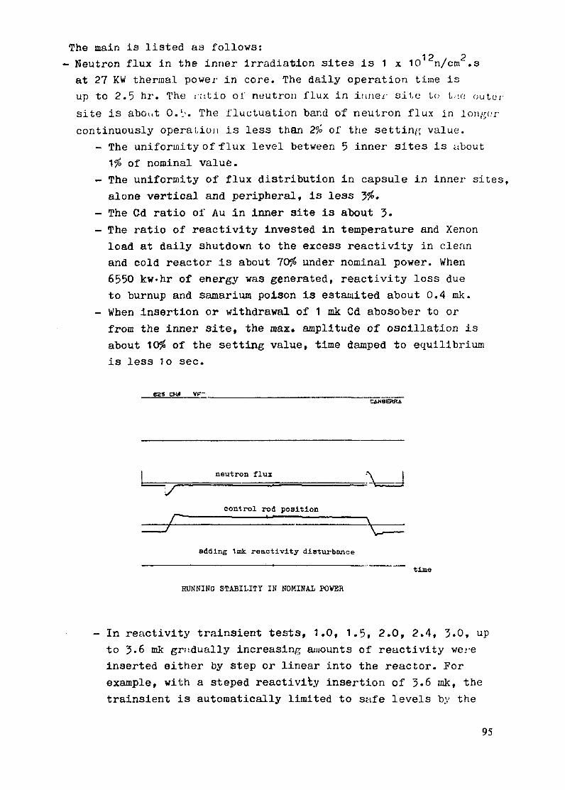
The main is listed as follows:
- Neutron flux in the inner irradiation sites is 1 x 10 n/cm2.
at 27 KW thermal power in core. The daily operation time is
up to 2.5 hr. The r;.tio of neutron flux in iirier site to t,:.: c outer
site is about 0.,'. The fluctuation band of neutron flux in longer
continuously operatioin is less than 2% of the setting value.
- The uniformity of flux level between 5 inner sites is about
1% of nominal value.
- The uniformity of flux distribution in capsule in inner sites,
alone vertical and peripheral, is less 3%.
- The Cd ratio of Au in inner site is about 3.
- The ratio of reactivity invested in temperature and Xenon
load at daily shutdown to the excess reactivity in clean
and cold reactor is about 70% under nominal power. When
6550 kw.hr of energy was generated, reactivity loss due
to burnup and samarium poison is estamited about 0.4 mk.
- When insertion or withdrawal of 1 mk Cd abosober to or
from the inner site, the max. amplitude of oscillation is
about 10% of the setting value, time damped to equilibrium
is less 1o sec.
525 C U V~-
CN~BER
neutron flux
control rod position
adding Imk reactivity disturbance
tine
RUNNING STABILITY IN NOMINAL POWER
- In reactivity trainsient tests, 1.0, 1.5, 2.0, 2.4, 3.0, up
to 3.6 mk gradually increasing amounts of reactivity were
inserted either by step or linear into the reactor. For
example, with a steped reactivity insertion of 3.6 ink, the
trainsient is automatically limited to safe levels by the
95

start-up neutron flux shutdown
control rod position fl. '8'
outlet coolant temperature
inlet coolant temperature
pool water temperature i
O 1 2 3 4 6 -R nurnning time, hr.
OPZEATIONAL CHAHiCTERISTICS OF MNSR IN NOMINAL POWFR
inherent negative moderator temperature coefficient. The
value of peak power is about '6 kw, and time to peak is about
6 min. During the trainsient, trie maximum wall temperature
of fuel elements is lower about 20°C than the water
saturation temperature at the same position level. Performed
these tests, the inherent safety characteristics of IMNSR
were demonstrated.
- Low radiation field is detected in operaLtion of-reactor.
The radiation dose rate in the reactor room working areamRemis less 0.0°5 -- in rooms about reac;.or room is ibout
0.01 -rt-, outside the reactor building is same as the
natural background, even in the 3.6 mk of reactivity tr'I.in-
sient, tne max. radiation dose rate is about 0.2 "--e- athr
reactor room work area.
During the first year of operation, the reactor has been
started up for 238 times, 107 times of them was operated with
power. Total energy generated has estimated about 6550 kw-hr.
Various the detectors, the instruments and the equipments are
operated normally. Testing the reactor behaviour,1397 different
samples have been analyzed. These samples used for calibrating
various standard specimens from the country and abroad; for
96

MNSR TRANSIENT 3.6mk. 1984.12.5
I80 - pma 76k w
power0
60 -- . 120-
/^~~~~~~~ Ij ^-<-/\^ * oo~Lo . . S^~-- lOs
C
Z _ : . . .... . .... . ... - So
< ; outlet coolant temp. g
20 ... er. - .4,0' -20 * | control rod position inlet coolant temp.
pool water temp.
IC * *- -- * * ~ **-''' i7-L-TIME F ROM R OD OUT, S. S ./,1
TIME PROM ROD OUT, S.
analyzing composition of ore, meteoric stone, marine deposit
and industrial products; for detecting poisonous elements in fruit
and plant, and for analyzing trace element in the atmospheric
dust and the samples of living organisms include hair. To date,
64 kinds of stable elements have been detected quantitatively,
including F, which half-life is 11.03 second, Co, which half-
life is 5.26 years. The quantitative order of detectable
element is from ppm to ppb.Moreover, some of short lived
radioisotopes have been produced for tracer investigation and
for the emitter of neutron source induced by radiation. The
results from performed.study and from analysis in application
exhibite that, design of reactor and auxiliary systems is feasible,
operation is facile, safe, reliable. The capacity of analizing
sunples is up to tens per day. Sensitivity and degree of accuracy in
analysis are high. However, in performance or in application,
the MNSR has rather potentialities.
Today, we are developing advanced design, it aims at increas-
ing suitably excess reactivity and decre:sing ratio of temperature
97
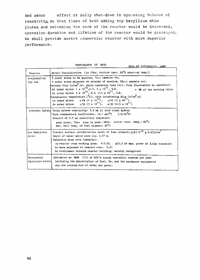
and xenon effect at daily shut-down in operating balance of
reactivity, so that times of both adding top beryllium shim
plates and reloading the core of the reactor would be decreaised,
operation duration and lifetime of the reactor would be proloriecd.
We shall provide market cornercial reactor with more superior
performance.
PERFORMANCE OP MNSR Date of information g9f
Feature Detail Specification (in 27kv, routine oper. 200C start-up temp.)
Availability 5 inner sites in Be annulus, 7c.c capsule vol.
for Use 5 outer sites adjacent to outside of annulus, 25c.c capsule vol.
;eutron flux (n/cm2.s), daily operation time (hr), flux fluctuation in operation:
in inner sites: 1 x 1012,2.5. 5 x 10 , 5-6. < 2% of the setting value
in outer sites: 5 x 101, 2.5. 2.5 x 10 , 5-6.
Irradiation temperature (°C), with irradiating flux (n/cm2 .s)
in inner sites: < 45 (1 x 10¹²), <40 (5 x 101)
in outer sites: <36 (5 x 10¹¹), . 32 (2.5 x 10¹¹)
Inherent Safety Total excess reactivity: 3.5 mk in cold clean system
Core temperature coefficient: -0.1 mk/°C (15-40°C)
Results of 3.6 mk reactivity transient:
peak power: 76kv time to peak: 360s. outlet cool. temp.: 62°C
max. wall temp. of fuel element: 92°C
Lov Radiation Overall surface contamination level of fuel elwment:.< 210- 9 g.U-235/cm 2
Level Depth of water above core top: 4.67 m.
Radiation dose rate (mRem/hr):
inreactor room working area: 0.05. _0.2 at max. power of 3.6mk transient
in area adjacent to reactor room: 0.01
in enviroment outside reactor building: natural background
Economical Estimated as less 1/10 of SPR's annual operation expense per year
Operation Costs including the depreciation of fuel, Be, and the permanent equipments
and the consumption of water and power.
98

CONTROL SYSTEM FOR THE MNSR
SUN HONGInstitute of Atomic Energy,Beijing, China
Abstract
The MNSR has two modes of control: manual and automatic. Theautomatic system is based on the computer, PDP-11/34. Because thecontrol system for the MNSR consists of only one control rod, thesystem for its control is correspondingly simple. Neutron fluxlevels can be adjusted between 1.0 x 100 to 1.2 x 10¹² n/s cm 2. Adata logging and annunciation capability is also available.
Two types of control systems have been developed for the miniatureneutron source reactor. The first is an operator's control system,the neutron flux level can be kept in a given band. Recently,thecomputer closed-loop control system has been developed and has moreadvantages. I want to deal mainly with the computer closed-loopcontrol system.
It is very safe, which is one of the intrinsic attributes ofthe MNSR, and the latest computers are very reliable so it ispossible to perform the control of the MNSR with a single computer.In our reactor a PDP-11/34 computer has been used, it's operatingsystem is RSXllM time share system. The control of the MNSR issimple; it only has a control rod, so the control of the reactoronly shares a little time of the computer, the main time of thecomputer is shared by the activation analysis and other works.
The control system includes the computer, the operating dataacquisition system and the executive body, as shown in Fig. 1.Since March 1985, the computer control system has been operatingand works well. The computer closed-loop control system has thefollowing characteristics:
A. The neutron flux is very stable.
The measured fluctuation of the neutron flux level (averagedin 5 s.) is less than 0.8% within 24 hours, as shown in Fig. 2.
B. The neutron flux level is continuously adjustable from 1.OE+8to 1.2E+12n/s.cm.cm.
C. A small fission ionization chamber is used for the measurementof neutron flux. It is sensitive with the thermal neutrons sothat the thermal neutron flux level can be kept constant andthe correct results of activation analysis can be easilyobtained.
D. Display.
The operating data of the reactor are shown on a CRT terminalclearly, as shown in Fig. 3.
99

channel
0. grade signal ~'~ l
1. voltage signal
2. position of rod
3. inlet temperature
4. outlet temperature
_______ 5. pool temperature
A~CTOR 6. radiation220
FIG.1 The block diagram of control system
7REA
1 Neutron Flux
Position of the control rod
0 20 40 60 80 100 120Time (iin.)
140
Fig. 2 The operating recording of the MNSR
100

10:23:1410:23:1510:23:1610:23:1710:23:1810:23:1910:23:2010:23:2110:23:2210:23:2310:23:2410:23:2510:23:2610:23:2710:23:28
9.968E+119.968E+119.968E+119.968E+119.968E+119.968E+119.968E+119.990E+119.990E+119.990E+119.990E+111.001E+121.001E+121.001E+121.004E+12
1.0E+12n/s/cmi.cm1.0E+12n/s/cai.cm1.OE+12ri/s/cm.Coi1.OE+12n/s/cm.cm1.0E+12n/s/cm .cn1.OE+12n/s/cm.cm1.OE+12n/s/cm .c1.OE+12n/s/cm.cn1.OE+12n/s/c'm.cm1.OE+12n/s/cm.cm1. 0E+12n/s/cm.c2m1.0E+12n/s/cm.cm1. OE+12n/s./cm. cn1.OE+12n/s/cm.cm1.0E+12n/s/c .cm
182.37mm182.37mm182.37mm182.37mm182.37.m182.37imm182,37mm182.37mm182.37mm182.37mm182.37mm182,37mm132.37mm182.37K>m182.37mm
T=21.74 42.19T=21.85 41.87T=21.96 41.37T=22.00 40.90T=22.00 40.94T=21.93 41.15T=21.89 40.86T=21,78 40.65T=21.70 40.33T=21.66 40,15T=21.70 40,65T=21.78 41.22T=21.85 41.44T=21.93 41.80T=22.04 42.01
15.2415.2415.2015.2015.2415.2415.2415.2415.2415,2815.2415.2415,2415.2415.24
1 5 . 4
1.17ur/s1.20ur/s1. 15ur/s1 .16ur/s1.23ur/s1.23ur/s1.25u r/s1.26u r/s1. 22ur/.1 .25ur/s.1.27ur/s1,29ur/s
1 .2,,3u; /
t .26ur/s;1.2Aur,'s
2246, lmv2243.7mv2243.7mv2246. 1m2246.1 mv2246.1 miv2248. Snim2248 ,StI.2251. Onm2257 i.4w
2253. 4m.225. 4nv2255. .4v225P5.39 ,'Jn '5F . nl,,
10:23:29 1.004E+12 1.OE+12n/s/cm,.c 182.37mm T=22.08 42.19 15.24 1 , 29ur/ 225 , 3 / ,r
Fig. 3 The operating data shown on a CRT terminal
E. Audible alarm can be broadcasted:
a. if any operating data go beyond the limit,b. if the executive body is out of order.
F. Convenient for activation analysis.
The control and the neutron activation analysis share the samecomputer, but they do not interfere with each other. And thecontrol system can give neutron flux value for neutron activationanalysis directly.
G. The operating journal can be obtained after the reactorshut-down, and accumulation of the burn-up and the operatingtime can be performed, as shown in Fig. 4.
REACTOR OPERATING JOURNAL16-APR-85
Time
09:20:4609:23:1210:00:0011:00:0011:30:4511:31:22
(s)51
1972405600578497886
Neutron-Fluxn/s/cam.c
2.276E+09 O.OE-011.001E+12 1.OE+129.990E+11 1.OE+129.945E+11 1.OE+129.968E+11 1.OE+121.980E+11 2.0E+11
R.H.mm-0.5
217.8187.7206.1215.6-0.5
Temperaturein. out. pool15.4 16.1 16.915,5 17.1 16,923.0 40.6 16.828,9 42.2 16.827.8 47.7 17.029.7 42.9 17.0
R.
ur/s0.011.051.211,331.360.52
Ref.0V7,3
2258,32270.52294.92307.1466.3
Int.fluxn/cm.cm
O.OOOE-012.983E+132.235E+155.830E+157.672E+157.687E+15
Warnins: 0 Hardware Error: 0Operating time: 2.1764hours Sum Total: 41.2372hoursBurn-uP: 7.687E+15n/cm.ca 5.440E+Olkw.hSum Total: 8,511E+16n/cm.cm 6.023E+02kw.h from 21-MAR-85 to 16-APR-85
Fig. 4 The operating journal of the MNSR
101

H. Reasonable.
Ony a few components are needed for an existing computer.
The computer closed-loop control system is satisfactory. Thiswork is not only useful for the MNSR, but also for other reactors.There are the common characteristics of reactors in the MNSR, andthere is not any danger in the MNSR to test the software andhardware, so that we can use it as a tool to develop more complexcomputer control systems for other reactors.
102

APPLICATION OF THEMINIATURE NEUTRON SOURCE REACTOR
WANG LIYUInstitute of Atomic Energy,Beijing, China
Abstract
The Miniature Neutron Source Reactor, built by the Institute of Atomic Energy.operates at a maximum power of 27 kW and a maximum available flux of1 X 1012 n/cm 2s1. It is used primarily for activation analysis in a large numberof fields - medicine, foods. geology, environment, industry, etc. Over 1500different samples have been analysed. The majority of samples are irradiatedbetween I and 10 minutes in a flux of 4 X 10¹¹ n/cm2s'- . The gamma spectra areanalysed using a locally developed software package called the SPAN on aPDP-11/34 computer.
The Miniature Neutron Source Reactor (MNSR) has been built
up in March 1984 in Beijing. The kind of reactor is very good for
neutron activation analysis. Since then abount 1500 different
samples have been analyzed with the MNSR, these samples include:
Food
Traditional Chinese medicine
Greens
Serum
Hair
Resin
Atmospheric dust
Meteoric stone
Ore (gold ore, iron ore and others)
Water
Stained glass
Alloy
Soil
others.
Accoudings to the irradiation time we classify the samples
into four groups, they are shown in Table 1, and the most samples
lie in the range of 1-10 minutes.
103

Table 1. The classification of samples on irradiation time
Time 1m 1-10m 10-60m 60m
Number 240 867 36 208
17.8% 64.2% 2.7% 15.3%
(from 84.4 through 85.3)_ _ _ _ _ _ _ _ _ _ _ _ _ _ _ - _ _ _ _ _ _ _ _ _ _ _ _ _ _ _ _ _ _ _ _ _ _ _ _ _ _ _ _ _ _ _ _ _ _ _ _ _ _ _ _ _ _ _ _ _ _ _
We also classify the samples on neutro flux as shown in
Table 2. The most samples are irradiated at the level 1.0 to
4.0 x 101 1n/s.cm2, so the radioactivities of these sample are
high enough to measure. Especially for the short live nuclide
the neutron flux level must be much lower, if not, the instrument
will not be able to measure the samples becouse the radiactivaties
are too intensive.
Table 2. The classification of samples on neutron flux level
Neutron flux
Number
4.0 x 10¹¹
713
52.8%
6.0 x 10¹¹
144
10.7%
8.0 x 10¹¹ 1.0 x 10¹²
39 455
2.9% 33.7%
The results of activation analysis are satisfied as shown in
Table 3, and we also are pleased with our facility, it includes the
MNSR, the capsule transfer system and the gamma ray spectrum data
acquisition and processing system.
First I want to describe why the MNSR is very good for neutron
activation analysis, in summary the MNSR has following advantages.
A. The neutron flux level is very stable. Now a computer closed-
loop control system has been developed for the MNSR. The neutron flux
level can be kept constant with the control system, and the fluctua-
tion is less than 1% within 24 hours. The measured value of the
variation of neutron flux level (averaged in 5 s.) is 0.8%. The
operating recording is shown in Fig. 1.
104

Table 3. The analysed results of the Mn standard samples
No Measured Value (ppm) Mean Value
1
2
3
4
5
6
7
8
910
11
12
13
14
15
29.42
29.1 5
29.24
30.72
29.99
29.68
30.08
30.92
30.40
28.87
30.24
29.53
30.73
31.06
29.99
30.00
StandardDeviation
0.68
(2.3%)
------------------ --------------------- ---------
Neutron Flux
Position of the control rod
20 40 60 80 14Time (Min.)
Fig. 1 The Operating Recording of the MNSR
105

B. The neutron flux level is continuously adjustable from 1 0 x 108
to 1.2 x 10¹²n/s.cm2 as per need of activation analysis, and to
change the neutron flux level is very easy.
C. The temperature is less than 450 C in the irradiation tubes
of the MNSR. So that the biological sample and the liquid sample can
be transferred into the MNSR for irradiating directly.
D. When the reactor is running the temperature will be stable
gradually as shown .in Fig.2, and the neutron spectrum will be
stable gradually too. Because the change of the temperature is not
large too. So that the satisfactory results could be obtained.
Tem. Outlet
.400C f . i,- r iIj , ";: '..'",: ' ., X ,'' /' ' '
40 C
0..K C - ^--(^ ;1 * *200C -t.. . ..... ...... - ................ .... ... ........
Pool
OOC I I0 20 40 60 80 100 120 140
Time (Min.)
Fig. 2 The Temperature Recording of the MNSR
(Neutron flux lovell .OX10 12n/s.cm2)
E. A small fission ionization chamber is used for measurement
of neutron flux. It is sensitive with the thermal neutrons. so
that the thermal neutron flux level can be kept constant. The
majiority of neutron activation analysis use thermal neutrons,
so that the correct results could be easily obtained. Table 3
shows the analysed results of 15 standard samples irradiated at
diffirent neutron flux levels.
106
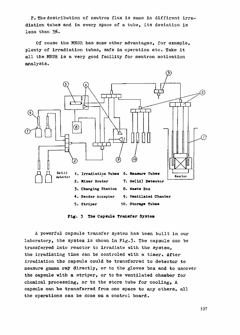
F. The destribution of neutron flux is same in diffirent irra-
diation tubes and in every space of a tube, its deviation is
less than 3%.
Of couse the MNSR has some other advantages, for example,
plenty of irradiation tubes, safe in operation etc. Take it
all the MNSR is a very good facility for neutron activation
analysis.
1. Irradiation Tubes 6. Measure Tube*
2. Mixer Router 7. Oe(Li) Deteotor
3. Cbanging Station 8. Vaste Box
4. Sender Accepter 9. Ventilated Chamber
5. Striper 10. Storage Tubes
Fig. 3 The Capsule Transfer System
A powerful capsule transfer system has been built in our
laboratory, the system is shown in Fig.3. The capsule can be
transferred into reactor to irradiate with the system,
the irradiating time can be controled with a timer. After
irradiation the capsule could be transferred to detector to
measure gamma ray directly, or to the gloves box and to uncover
the capsule with a striper, or to the ventilated chamber for
chemical processing, or to the store tube for cooling, A
capsule can be transferred from one space to any others, all
the operations can be done on a control board.
107

A matter of especial importance is the application of a.
change station. it connects across the two loops of the cap-
sule tranfer system, it can prevent the active air from escap-
ing into laboratory. The capsule transfer sustem is very safe.
An automatical capsule tranfer system controlled by a
computer is under development. In the future the capsule
transfer system would be more advance and powerful.
The gamma ray spectrum data acquisition and processing
system, it includes a Ge(Li) detector, a Series-80 multichannel
analyer and a PDP-11/34 computer. The resolution of the detector
is 2.0 kev, and the efficiency of it is 25%' But the application
software is developed by us, it called SPAN ('Neutron Activation
Analysis Package). The SPAN has following characteristics.
A. Full Functions
a. The peak analysis.
. To search peaks automatically.
· To fit background line.
* To resolve multiplets.
· To calculate the central channel, energy, net area,
error, and FWHM of each peak.
· To do geometry corrections.
· To identify nuclide.
* To calculate the radioactivity of the nuclide.
· To print the peak analysis report as Table 4 and
Table 5.
b. The activation analysis calculation.
* To correct the irradiation time and decay time.
· To calculate the concentration or detection limit of
each element.
· To print the activation analysis report as Table 7.
c. Remote control of the MCA.
d. Many auxiliary functions:
* To list analysis reports as Table 8.
. To modify the analysis reports.
· To transfer spectrum data.
· To calibrate the instruments.
· To do automatic recalibration of energies.
· To edit the nuclear data library.
· To edit the elements of interest.
108

Table 4. A peak analysis report of the SPAN
*tlt lttU tt.St StttlttttZt. Z Sttttttt$st* SPAN SOFT~iARE PE ANALTSIS REPORT tt 10:06:53 16-APR-85 tttr tt«nttttttrt 2 Grout tttttUtttrive
Geout rhubetr: 2 Group nuter: 3 Activ Tie: 60O.OsSpectru rnuber: 2635 True Tie: 609.0s
Froe 40 Chamel to 4000 Chnnel
G6[F F1 uclide alf-lite Enerrt Intesith Ibst-Intene RadioactivitvNo Centr,Ch, Rar-Entrt Peak-Are
1t 93.342C 210.503C 215.604 27.315C 495,07
6C 49.537 564.248r 590.859C 651.53
10 671.14
1C 76.8412C 791.5013 930.0014 964.49ISC 1076.34
IC 1080.1717 1207.2018 1228.3819 1294.16
20 1325.85
21C 1462.0122C 1467.5823 1617.5924 1650.70
25 1746.52
26 1796.U27 1830.1328 1945.6929 2096.4830C 2114.37
31 2210.7332 2270.6133 2311.3134 263.0435 2657.36
36 2697.65
37 2767.0338C 2863.1739C 2867.2740 3285.53
41 3310.1642 3516.6043 3894.5444 3938.6045 3963.11
73.284ev165.120Kev169.118;ev218.264Mev388.1464ev
391 .39Kev442.351Kev463.199Kev510.755Kev
526.119Kev
616.T77ev620.428aev728.943Kev.757.533ev843.591Kev
846.590Oev946.100Kev962.688Xev
1014.2171ev
1039.037Kev
1145.684Kev1150.053(ev12U.7.5381ev1293.4664ev
1368.503Kev
1407.919Kev1433.975Kev1524.463tev1642.522Kev1656.532Kev
1731.996Kev1778.849Kev1810.711Kev2062.557Kev2081.5764ev
2113.114Kev
2167.410Kev2242.M47ev2245.859tev2573.129Wev
2592.403ev2753.900(ev3049.5158ev3083.9811ev3103.1 46Xev
131.3c212.4c122.2c203.8c299.2c
84,9c4740.0c
5. lc2700.9c
356.9c
202.8c110.Oc56.8c
111.2c1640.Ic
2557.8c46.8c53.3c
474.8c
499,8c
244.1c59.6c87.6c
1197.2c
3191.6c
59.2c198.1c67.3c
2766.8c216.1c
236.8c3622.4c365.6c452.9c140.6c
169.4c
2892.1c273.9e
45.1l569.1c
189.1 1623.5c
43.7c2474.5c
816.9c
Error
43.51%19.22232.11131.91%11.57%
35.9221.69%
48.06I2.39%
10.791
15.71127.54%48.31%31.6012.99%
2.26%37.09%38.00%7.94%
7.68%
12.36:43.44228.U2
3.881
2.072
43.59%15.32134.93%2.13%
12.73t
10.671.83Z7.97Z6.57t
13.071
14.00%
2.05%9.15%
42.9115.792
12.5912.89
21.1522.0463.602
0.00 1.09tev1.35 0.9?3ev1.35 0.93Kev0,00 2.80Kev1.37 1.711ev
1.37 1.71Kev0.00 1.37Kev0.00 1.39ev1.38 2.79Kev
0.00 1.25Kev
1.69 2.47Kev1.69 2.47Kev0.00 1.47Kev0.00 2.41Kev1.72 1.57ev
1.72 1.57Kev0.00 1.80Kev0,00 1.62Kev0,00 1.73Kev
0.00 1.78«ev
1.73 2.62Kev1.73 2.62Kev0.00 2.01Kev0.00 1.99Kev
0.00 2.17Kev
0.00 1.97Kev0.00 2.05Kev0.00 1.095ev0.00 2.27(ev1.31 2.864ev
0.00 2.395ev0.00 2.35Kev0.00 2.52Kev0.00 2.57Kev0.00 2.26Kev
0.00 2.57Kev
0.00 2.48Kev1.45 2.79Kev1.45 2.79Kev0.00 3.92Kev
0.00 3.43Kev0.00 2.89ev0.00 2.35Kev0.00 3.09ev0.00 2.83Ke
Hs197* 2.400tOIH 165.00OKev 0.32000 133.945Kev 5.496EOldPs
Sr87M 2.810Et00H 388.400Kev 0.82500
Snl13 1.152E02D 391.400Kev 1.000001128 2.499E+1M 442.9171ev 0.20500
T1208 3.100EtO 510.808Xev 0.23000Amih. O.000E-01S 511.000Kev 1.000001135 6.700EK0l~ 526,500Kev 0.11300
Ir80 1.760E01l 616.200Wev 0,07000C138 1642.420kevDE
A128 1778,900CevDPas27 9.450E00H 843.800Kev 0.72000
IMn6 2.587EtWO H 844.600Kev 0.9900
Wl27 9.450EtO04 1014.400Kev 0.28000K42 1524.700kevSECu46 5.100Ei00 1039.0Kev 0.09000
C138 2167.550keDE
A128 1778.OkevSEInl16a 5.410Et01H 1293.430Kev 0.85000Ar41 1.830~EOOH 1293.600Kv 0.99100Ia24 1.502E1OIH 1368.534Kev. O. 90
Eu152m 9.300E001H 1408.025Kev 0.01700V52 3.760E+O 1433,60Kev 1.00000X42 1.236101H 1524.700Kev 0.18000C138 3.724o01H 1642.420Kev 0.40000C138 2167.550kevSE
1124 2753.92lkevDEA128 2.243E400M 1778.?00ev 1.00000I56 2.587Et00f 1811.200Kev 0.30000Ca49 3084.410evIS37 3103330kevDE
388,400Key 5.391EtO1drs
391.400Kev 1.271EOldps442.917Kev 3.793Et3dps
2614.60Kev 2.149Et03dP s511.000e y 4.942Et+2dPs
1260.500Kv 5.910E02dps
616.200Kev 6.11?EO2dps
843.800Kv 6.122EO+2dpt
846.600Kev 6.92Et02des
843.800Kv 5.257E+02ds
1039.000tv 1.754t03dPs
1293.4301ev 5.279Ef02dps1293.600Kv 4.528ME02dps1368.534Kv 1.250E+O3ds
1406.025ev 1.394E03drs1433.960Kev 8.050( lds1524.700Kn 1.595E+02dps2167.5501ev 3.128Et03ds
1778,.00Ke 1.745Et03dps846.600:v 5.953Et02ds
Inl16* 5.410E4019 2112.140Kev 0.15000 1293.430Kev 6.235Et2dpsMnS 2.587EtOOH 2112.600ev 0.15000 846.600Kev 6.235EO2desC138 3.724EO111 2167.550ev 0.54500 2167.550Kev 2.99OE0O3dpsNh24 2753.21lkevSE
Ca49 304.410krvSE
S37 3103.330evSE1124 1.502t41H 2753.921Kev 0.m9900 1368.534Kev 1.109t03s
C»49 8.720Et00 304.410Kev 0.92100 3084.4101ev 2.008EH)3dps837 5.060O0W~ 3103.330Kv 0.99700 3103.330Kev 6.155E02dps
6aa $spectrum analysis finishe has 45 peks. 18:39:00 16-AR-85.~·~·~l·~·r~r··l~·r·1-···~~·d ·1 1ew·w·
109

*
». 0
C
.r
r o
r -
0 -o
to
0 -
-r ve
n -o -o
v
_
_:I
LC
4.
9 -o
-
Q: 1
0 cl
_
_e
CO
IC V
'y"
_r
_
_-
_
It>
vr
r^0
0 00C
L
J
L
U
LaJ
m-O
e-
~0E
o c r-.
r r
In n
_n
In 0
La
La
La*
La
Lis
No
tVi
-^
o
_
difl --
I·
G~
0
-'0r-
re en
Kf of
*
o
*41'4
ro -
r s, e
w o
x o
' -
r- .C
0
0f o
o. O
0
O
-_
Q
O^
O.
t *0
%0 r_
r *<
- O
C
tr- r.
O
_-
O»n
M
_^
<
o0"
oa,
-,
kJ000)
P4
o,
E02
0ap4 0.,1(Do(
rxi
_ o-*
o
r. ,-
*
e W
..
t I Q
0^
1_
t C
.Cen
r '
LaL
L
a L
a
La
f<
ra T
-
0=
'0
)
I q 0
0
00
,Qq.
_o o
to
O
s .0
r o-
_"
uo o
OQ
r-
_
Ln
o
_>
*o
re C
C
,_
-.
en
en
4'
e5,ft
c~
-J L
aJ L
a- U
L
.0 O
4
0
en
Sf
¢
n
,
80
' 0t
0 O
-.
..
.
e°*ru
'°
Ow
~~
~a
--
-*
_
0rs
o.
-oo
-q
ro
_-
c
a
Vo
000
Q
o e
enQ
en
-X
re
0 _
o
_
060~
to
0<
40^
-.
O
_O.-
r. -
r.O V L
U
: ^
_
^
_
s-_ ^
_
_
° °
S 8
; O
g O8O
§
Ci
Cci '0
C.; C
.1
O
0L
U
LU
O
_o
-o U
-i
.5 -
-.
C-
.0 .0
»
,*
I t 0
-r
C4 C.
o o
>
*
,-0 0
- 00m
-300
'CC
o 0 *o
o
-0 -C
ur
en
'0 -
o- C
on
t en->
-C
r*0
.50
oo
0
tG
0-C
ehio 0 >
0
0m 0
r
en
.O
Qr.e
) -
-C
V. O
.0
en re
0
o
-o
_
*
o
O*
o_
re- OO
:o-C
O
-Z
mC
C2
t
'O C
. C
. r'
0 r
r
t ooo
_o
t
to v-
)r- r«
e
_o _c
_ _
_o r
ci re
r1
rsr r
s ,
r. rsrM
7i .i
ec~
~~
~~
~~
H
rC
r; 0
-.to
o' 0
p;
_ 4.
0 * 0
:0 e:
oc- 0
o-'o
S
r- oS
^^
r-ir
r "
~hoo^-<*·-ir'-^^^*^,
* ^
*
r o
o -^>
-r
Ce
tY
*
r .-
m
, r
o-' *
rCl
-0 *<
» -o o
.o'.*
a.-
r IQ
CeY
-, t
.0
-~A
W
e ..
'
-er
LL
~~
~~
L
to .4
~ 00
0 0
.0:
0-.r5..
-,
I o.
r -»
f t
i0u_'b
toIRin
en
X.
to
;v --r
0 0
0 ,
55
r-o<
rXW
c
oo
> *
'
*r ~* ^ r
000000
e ern
_-C
* r
r. h
1r 4 r C
c <
50 ,,I
L
0-e
---
C
C
_ _
esr rs
nr f
' to '
0
0 00
0
>0>0 00.000
o oK
o
i?>
o
o Z
O
O
o
.0 -
o to
Cer
r-. to
o _
._ -0
ra
.
0
en
0
In r
._ 0
en en .r
en -o
CO
~~
~~
~~
~*
CO
C
C
C
Ce
eC
C
ie
C
< _
re rC
O
en
en
en
Ve
re n
ren e
La
La
r0
La La
La
La La
La La
La
L
a
La
L
ay
(
c t
*i t
v n
rttrzv*
^^XX
~
S^
"33'*3 ^
'S '
n
C-r*. n
"
ra
Las L
0.ow
Z
U
C
n
C
re -
en
0.
-C
..-.
04'0
0·
0
CO
0
C
00
Ce
-en
~ C
. t
-
~OO4=
gggto
00C
'
en 5.4
.
o __- -
--
m
0 c.
en
0 O
.c;
o·-U
*~ o
rP
5" O S
`
or
.^^-»rr~o
00 0
r'-' r'-5?
r
tCs -
--
0 o
o
rC -O
_
_
CO
C
o
00 4
r r
*- o-O
.
CO
Cto
-
-... .
.
eo
oC
*'
..
r -
C
o .
r- .Q
*.
OO
C.
00
.40
o0
004' a
-,_
0-.r
._ .
0 r
r *C
_O
'i U
i rt o
.-
Vy '
r. t
--
--
--
--e
o r
co
_. -
o
en.
04
*o
:R r.rC
0o
r't C
0
C_
o- pi
° 0
en
ens r.-.
D
e r.
C*
or vn
C~ I'r
1? 1
m g,
"
-f:,
o-t.r.
0 t
-o -
0
Ci
93
r
riai
r> !K
I
D
_r o
O
e o- r
.C
r.< r
o
C r.
r-. en C
.' ..
^. >
r. _0
w9 o
O4
00 r-C
e
f o
.0
e r
-C
o
ixi oo
.. _.
cl
r.
.m
:o
tor .
en 1
.tt 1c
-C
c r
"
e>
C
t -
e_
c EM
e s
rt oro
rr
r o
Cr
° m
o C
..
..
.C
. C
. I
.C
.
.C
. ..
r. g
oen M t
fr-.r _ L
r.
0
U
o r
<*
-r
CD
0
w
Oo
c
T^
«rri v7 vo.rU
, »ir
0
110

Table 6. The peak analysis report of SPECTRAN-F
for the above spectrum11 a * allllll* 1 Aa 1 8 A 1 A 1 1111A11 8 AA A lll lllll l lll 111 1 * 1
A 8
g 8
lit lllllllll 1tll tll l11)lll llll llll llll l lllll ll lll l
rsi;i.i CliC;i;:t-f :Ž.lI S&rfii[E
l;-yt-8:?;':<4:¢
i "H i t j I 5 F (. A E T E
.4 MdIT f.i: I / 1[TECIG iflWM:F: I G' C(TRY MUfim: I
4K Mil , *.M.kl: l.'[tC;i.Uh S:Z0: 4096 CWfELi
44.1;. ;.r JOiaiis4 CLi40Tl.: .a *
A4v.U t( f6.cif.j*l :'l.LS: 4 C EACUl SiE Of fEAt
FE: to-liCiE[ F0C1[C.: ;:.4ITi4TllIfATOlti EtilERCGI llw : f- 1.0. LtV:;lt L.Ji'il::; i. 51i SIGCA WCiTlllUT
NTI!i LET .Wa rS I'i(f:M.'A
fElT:1L. ITA1 44. Ql kECl Ir Fktl IlATi.W110 L YLYZEk 1MO:Siwt.P I(KStlfTr0: tUl:.
,W4(;'.(1 0f: 6MAR;oALCi SITPhi. [( i-.M4-85 iA 11:47!:0
4L.i:ti Lilt ilf:C 40 W. SEUWIS
13-M-l517:041:47
PEAK AALYS 1S
f ST11T - STOP CEITOI8 0D OT WY .hL oDiwAC uv zv
SMsS UC~o Tr JEA OM WfITtco.S CaOTIS CXoJS
InuLIKS
I"K» AT ~Mt 59.6 Frgf a IILTIum T *UL'SIS11 23- A2 31.31 25.4 2.0 10M3I. I25i.2 23 - 2 3.01 2.59 2.0 2175. 32t0.3? 2- 42 38.30 31.55 2.0 5202. 45347.4 23- 42 42.54 34.481 2.4 104M1. 5t902.'. :;.3 - 2 44.1 37.32 2.0 105764. 72043.
4* 23- (2 4.' 40.A4 2.0 l(47. 5W049.' :: i: 54-.: ; 43.8l.2 2. 130,;. J2W64.
St l: - \t 153.80 121.5? 1.4 lU4407. 54001L91 i; - 3i 187.32 147.1 4.3 2.251. n2002.
1l' 3 - ,'2 3ll.03 244.4 1.3 321714. 53872.
;ti i *'.- G54 ? 735 - 7.5
.9C 703- 72Yt 7.- 7?231 75 - 762
332 735- 7U
34 830- 34435; 6;- 27334 1853-373
K 90- 130
43 I17 -14144 3 * -1A04S? 1091 - 11824' v1 - 1122
4t 2n - 2074rt 202 -20744it 208 * 11
8t7 2064 - 11l;215 - :204
9 222:42 - 226a
I1; 332 - 334
620.85
o50.14652.47
l81.47710.48719.21722.20742.22747.H6714.72837.45U4,.74
873.5490.26
922.12
1114.73
2'03e.u
2114.12
;m.M
2253.712259.792341.12
U40.79 1.5495.37 1.S503.55 1.5510.04 1.55ll.iO 1.5534.55 1.9557.25 1.i3S4.v8 1.356.42 1.4
51.87 1.5i. .60 3.878ii. I.a
4M.75 3.8712.79 .i719.42 1.4723.40 l.i7.i.1U 1.7785.9 1.7810.55 1.7841.*4 2.U7.44 1.7873.26 1.7
15.4.27 2.21606.03 2.21643.37 2.31447.73 2.3
1714.22 2.317M4.4 2.3
2164.2 3.2
35765.
32247.30028.
35151.33255.42700.
31025.14716.
32330.2903.14282.
5t425.41188.24441,2M43.
*MM.4ina.
1131 .2I?.
ILL.Sv.
16.lot.
20140.2 009.
2173.2312.
34455.32493.32482.32478.
2U12.27124.21726.27002.26142.3478.24S5.
27482.33085.11m.
nlu.24473.
25134.
S%3.
4524.33721.
213432.5837.
271.sia.
3074.716.45i.
6i.740.
10218.2101.
oC.Mt.2455.2102.7740.
12714.1U3t.
303.31144.4370.1487.
57231.16i88.
3.2 6.140 024.1 6.94Ef024. 64.91 025.4 6.&EtO27.2 6.4£(10210.3 6.94if02,.1. I ,9 020.1 tlUttlt SE-75,O-57
13.4 Ilt0U) FU-2410.4 5.17t0l0
22.0 1.75140012.6 1.010021.5 I.OlEfO8 TL-200,-2:2,23.2 l.ilEtW -22,*Ml-kb36.7 MUItt115.3 4..1-014.4 6.21-01 CS-134.S-122S.l 6.l1-01t.I 1.E.tO03.I 1.i4EtO3,1 I.it0f O -1-1),1 lllt1ltt1.8 #0028035.i l. 1EtO04.0 1.16t002.3 Us8tUm0.4 2.301400 U1-1244.0 2.30E001.7 2.3W S0 -124,1-131,23.4 ut181tt 2-950.3 2.440015.1 008811l 1-132tC0-5
1£.2 1it2L811.0 I.341002.5 i.34Et4
4-RD0
'-9s
103. I8. 3.3 1.71?E00 tL-140W. t0. 17.0 1.711[001. 334. .5 2.40([00 a-3e
75. 1.4. 1.3 2.40[0047. 140. 11.5 I1U11141. 5. 22.1 1.2KE0O U-21435. al. 17.4 1.2l1t00 XE-138i. 10l. 1O. 8.44E-01 TL-.2S
kRli OUOT»*IL0 AT I.0M StiAFEI ClOI*tiK4 LUEL AI ;5.OI
; - r* ;l(iT T LlSlS ttEldW iE I
.- K4Tilh.' Y liET tb(4Wt HiE TO to 1 OFt il-SO ISRVELE4T- XLtrlLdtl i515RO CltM llI Cfll * 4
111

Table 7 The activation analysis report of the SPAN....................... .. ........ ... ......... ................ ....................... .......................... ..............
No: 2U6
ACTIVATION ANALYSIS REPORT
Irradiation Tice:Samle Nta:
Ad < 2.38E-0'2ir 7.332l1. 151-Orlm
Co < 5.81E-02,iEu 1.75M0.73E-OlmHId < 4.01E~POnK 1.3770.481E£2~tHo < 4.85Et01s ( .< i.8EO2rP
Rb < 3.MW+lm9Sb ( 1.47EM0lSr 2.36kt0.277E1Ot.lTl < I.01E03tmYb < I.MEMi01
10.00XPEN-
AlCaCsFeHoLaNab
ReScTaToZn
2.729i0.02.3530.I
< 2< 1.< 1,< 4,
1.142*0.('<22
< 1<1< 5<2<2
000F ecaw Tim: 136.OOOOs CollectiM Tim: 600.00 Neutron Flux fenitv: 1.0OE412n/ics.c.n Sawle Nlht: 0.103401
O5CO1m As < 3.10E+ E0m Au < 4.3E-01m *at V.275il.7B113XtO48E03m Cd < 3.S8EtO1Pp Ce < 3.65E02p~ Cl 1.TlSO.036Et.2m~
.6OK~E+O n P Cu .206i.707E~ m hb < 1.79E-02p Er < 8.03EO00m
.t7E~ m 6a < 2.71E0,,~r Gd < 2.29EO~ S6 e < 2.29E1Om6,J*OX m I &.307t1010O6E+0m In < 2.0E-02m It < 1.44t 00m.42E0m tLu < 7.74E[-lpr I 2.22210.06E02~m Hn 1.25I0.029CEOdW024E~2m b < 7.00EK01POlM d < 8.2SE40m Ni < 2.86E02m.14E+O4p, Pd < 4.25E00~ Pr < 4.58E+01,m < l.MEOOm.1E-02m Rh < 1.5X2E~ Ru < 5.13E01Pm S 5.1750.117E04pf.ME+Olm Si < 3.83E+03pp Ss < 1.72E-01m Sn < 2.0El0pm.83Extm To < 3.20(t0 t w h < .4E-4O1m Ti < 7.'SEOm,2 p+02 U < 1.3E-OlW V 6.389i0.975E-02n I ( < 6.l1E+00.70EO2rr Zr < 1.57E+O4m
Alalied b_ - 18:44:28 1-APRS-5
B. The
a.
analysis results are accurate.
No peak is lost.
We have used the SPAN and the SPECTRAN-F (CANBERRA's
software) to analyse the same spectrum, the part of the
results is shown in Table 5 and 6,the results were care-
fully checked and compared, as shown in Fig.5, we can
find all the peaks, that can be found by the man's eyes,
have been found by the SPAN, but some peaks are lost by
the SPECTRAN-F, these peaks include some intensive ones.
b. The integral peak technique has been used.
This technique can produce a step background line, it
can finely describe the background under peaks and can
directly subtract the background from a spectra. So the
accurate value of net peak area can be obtained.
c. The SPAN is powerful in resolving multiplits.
The least squares fitting (LSF) method and the Experi-
mental Peak Shape Function have been used for peak analy-
sis. They are capable of resolving the multiplets, as
shown in Fig. 4. The limit of identification for closed
doublet of equal intensities is about half of the FWHM.
112

Table 8 The final report of activation analysis
t***
ACTIVATION ANALYSIS REPORTThe Institute of Atomic Enersw
****
1409Hair-1
unit = ppm
2269 3409 0Hair-2 Average
________________________________________________________
AlA1AsAuBrCaClCoCsCuDYEuGaGdHAHoII rIr
LuMflHnNaF'dPtReRhSSB.TeThUV
<2.62E-021.134i0.043E+01
<8.25E+00<1.26E+00<1.37E+00
5.29110.378E+028.486i0.128E+02
<1.29E-01<6.73E+00
6.8671i.181E+00<4.65E-02<1.24E+00<7.59E+00<3.40E+00<9.95E+00<4.25E+00<5.10E-01<5.22E-02<3.82E+00
7.848i1.434E+02<2.07E+00
1.019i0.092E+025.099i0.429E-015.639i0.090E+02
<6.79E+00<4.?9E+00<4.13E-02<6.25E-01
4.448i0.248E+04<4.02E-01<7.63E+00<2.28E+00<3.27E-01
4.484i1.372E-023.714i0.434E+01
<2.82E-02.1.207*0.046E+01
<8.94E+00<1.37E+00<1.49E+00
5.664i0.405E+029.105*0.138E+02
<1.40E-01<7.32E+00
7.451i1.263E+00<5.05E-02<1.34E+00<8.20E+00<3.65E+00<1.08E+01<4.62E+00<5.51E-01<5.64E-02<4.13E+00
8.49511.541E+02<2.24E+00
1.097i0.099E+025.477i0.461E-016.057i0.096E+02
<7.34E+00<5.40E+00<4.49E-02<6.74E-01
4.750i0.265E+04<4.36E-01<8.28E+00<2.47E+00<3.55E-01
4.748i1.465E-023.989i0.469E+01
<2.62E-021.170i0.037E+01
<8.25E+00<1.26E+00<1.37E+00
5.477*0.187E+028.795A0.309E+02
<1.29E-01<6.73E+0O
7.159i0.292E+00<4.65E-02<1.24E+00<7.59E+00<3.40E+00<9.95E+00<4.25E+00<5.10E-01<5.22E-02<3.82E+00
8.172iO.323E+02<2.07E+00
1.058*0.039E+025.288i0.189E-015.848i0.209E+02
<6.79E+00<4.99E+00<4.13E-02<6.25E-01
4.599i0.151E+04<4.02E-01<7.63E+00<2.28E+00<3.27E-01
4.616i0.132E-023.851O0.138E+01
AralYzed b_ 08:10:22 13-FEB-85
I
Fig.4 The step background line and the ability to resolve multplets
113

00,
*1C
K''B
I I I I I II -II l1I -The lost peaks by the SPECTRAN-F 1 1
Fig. 5 The Comparison between the SPAN and the SPECTRAN-F
C. Very easy to use.
a. Multiple options are supplied for user.
b. Parameters will be memorized.
c. A single command is enough to finish a task.
d. Many complex commands can perform a series of tasks.
e. 'LEARN' function is very useful for a lot of common
samples.
f. LOOP and PAUSE are available.
g. Lowers work as capital Letters.
h. HELP is available
As mentioned above the facility is a very good tool for
neutron activation analysis, and the facility also suits for
trainning of the analyst. In our laboratory the trainee can
learn the technique of neutron activation analysis, which in-
volves the knowledges of the nuclear physics, the nuclear che-
mistry, the automatic control and the use of the computer etc.
Of course the MNSR is a neutron source, it also can produce
some radioactive isotopes, and it also can perform neutron photo-
graphy and other research works. The MNSR is very useful, safe and
reasonable, hopefully, the MNSR would have more and more users in
the world in the near future.
114
MNSR-A SATISFACTORY TOOLFOR TRAINING AND TEACHING
GUO CHENGZIANInstitute of Atomic Energy,Beijing, China
Abstract
The MNSR is an epitome of general reactor in view of the
structure and behavior, because the reactor is inherent safe,
simple in structure and convenient in operation. It can not
only be utilized at neutron activation analysis and produce
short lived radioisotopes, but also is a satisfactory tool for
training and teaching in universities and research institutes.
Since the reactor reached its rated power, many experts and
students from home and abroad have visited this facility. They
are all interested in its simplicity, security, reliability and
practicality. In particular, its operational constraints are
minimal, the reactor is simple so it is easy for a student to
understand, there are no automatic trip devices to interfere
with the experiments, consequently students are able to inves-
tigate the nuclear engineering characteristic of typical light
water reactor in a very direct manner and understand those
concepts learned in the class room easily.
Briefly the typical experiments which can be performed on
this reactor are:
(1) Critcial test and rising power test.
(2) Absolute neutron flux measurements. axial and radial
flux profile measurements.
(3) System cold excess reactivity measurements.
(4) Control rod worth calibration.
(5) Temperature coefficient of reactivity measurements.
(6) Observation of poisoning reactivity.
(7) Determination of absolute thermal neutron flux of reactor
from xenon load.
(8) Spectrum index measurements, axial and circular related
flux measurements in irradiation site.
(9) Reactor transient experiments and comparing their results
with that of theoretical calculation.
115

(10) Studying the static and dynamic characteristics of reactor
instrumentation(e.g. a high sensitivity helium detector,
miniature fission ionization chamber, miniature gamma
ionization chamber, titanium ionization chamber, cobalt
self powered detector, platinum self powered detector).
(11) Investigation of optimum distribution of reactivity.
(12) Studing beryllium reflector influence on the reactor con-
sisted of high enriched uranium and light water moderator.
(13) Automatically start up and unattended operations being
used by computer.
(14) Miscellaneous studies.
Moreover MNSR is equiped with a PDP computer, multichannel
analizer and neutron activation analysis program. Power,
outlet and inlet temperature, control rod position, gamma
dose, integrated flux were recorded by computer.
In the end we would like to serve for training licensed
operator and activation analyst from home and abroad in short
date.
116
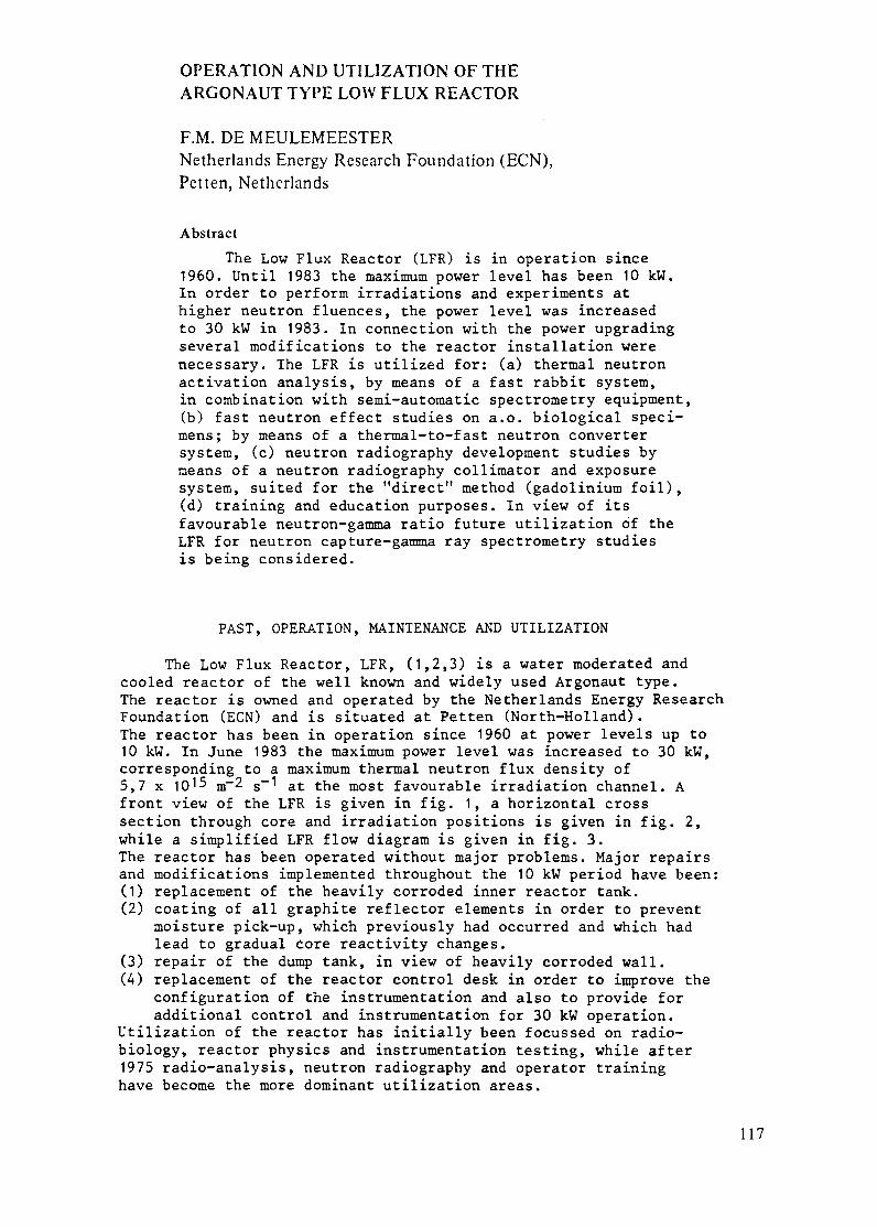
OPERATION AND UTILIZATION OF THEARGONAUT TYPE LOW FLUX REACTOR
F.M. DE MEULEMEESTERNetherlands Energy Research Foundation (ECN),Petten, Netherlands
Abstract
The Low Flux Reactor (LFR) is in operation since1960. Until 1983 the maximum power level has been 10 kW.In order to perform irradiations and experiments athigher neutron fluences, the power level was increasedto 30 kW in 1983. In connection with the power upgradingseveral modifications to the reactor installation werenecessary. The LFR is utilized for: (a) thermal neutronactivation analysis, by means of a fast rabbit system,in combination with semi-automatic spectrometry equipment,(b) fast neutron effect studies on a.o. biological speci-mens; by means of a thermal-to-fast neutron convertersystem, (c) neutron radiography development studies bymeans of a neutron radiography collimator and exposuresystem, suited for the "direct" method (gadolinium foil),(d) training and education purposes. In view of itsfavourable neutron-gamma ratio future utilization of theLFR for neutron capture-gamma ray spectrometry studiesis being considered.
PAST, OPERATION, MAINTENANCE AND UTILIZATION
The Low Flux Reactor, LFR, (1,2,3) is a water moderated andcooled reactor of the well known and widely used Argonaut type.The reactor is owned and operated by the Netherlands Energy ResearchFoundation (ECN) and is situated at Petten (North-Holland).The reactor has been in operation since 1960 at power levels up to10 kW. In June 1983 the maximum power level was increased to 30 kW,corresponding to a maximum thermal neutron flux density of5,7 x 1015 m- 2 s- 1 at the most favourable irradiation channel. Afront view of the LFR is given in fig. 1, a horizontal crosssection through core and irradiation positions is given in fig. 2,while a simplified LFR flow diagram is given in fig. 3.The reactor has been operated without major problems. Major repairsand modifications implemented throughout the 10 kW period have been:(1) replacement of the heavily corroded inner reactor tank.(2) coating of all graphite reflector elements in order to prevent
moisture pick-up, which previously had occurred and which hadlead to gradual core reactivity changes.
(3) repair of the dump tank, in view of heavily corroded wall.(4) replacement of the reactor control desk in order to improve the
configuration of the instrumentation and also to provide foradditional control and instrumentation for 30 kW operation.
Utilization of the reactor has initially been focussed on radio-biology, reactor physics and instrumentation testing, while after1975 radio-analysis, neutron radiography and operator traininghave become the more dominant utilization areas.
117

Fig. 1. The LFR with in front the irradiation trolley and on top
the neutron radiography facility.
Fig. 2. Horizontal cross section.
118

Fig. 3. Simplified LFR flow diagram.
POWER UPGRADING AND ASSOCIATED TECHNICAL MODIFICATIONS
The maximum power level has been increased from 10 kW to 30 kWin order to perform irradiations with neutron fluences up to 1020within the normal 8-hour daily operating period.
Associated with the power upgrading the following technical modifi-cations have been carried out:(1) Increase of the cooling capacity of the primary and secundary
cooling system (in order to maintain the temperature conditionsof the fuel elements at "10 kW" level) by:- installation of an additional primary cooling pump with a
three-fold capacity increase in relation to the existing pump- replacement of the secundary cooling pump by a larger pump
(also three-fold capacity increase)- installation of a larger, plate-type, heat exchanger- adaptation of piping and lay-out to the increased flow rates.
(2) Improvement of the biological shielding around the reactor byinstallation of additional concrete blocks and other localprovisions (a.o. around thermal column and irradiation trolley).
(3) Adaptation of the primary cooling control logic, in order tolimit reactor vessel fill-up rates at Keff > 0.95 to 20 pcm.s (as required by the Dutch Licensing Authorities).- a level control system which prohibits operation of the large
pump between the levels "bottom fuel" and "normal" ("normal"means : reactor vessel completely filled with water).
- a level/time relais control system which reduces the flowrate of the small pump by means of an electromagnetic valvecontrolled restriction in the delivery pipe of this pumpat the water levels corresponding to K ff > 0.95 anddp/dt > 20 pcm.s- 1.
(4) Installation of air-activity monitoring instrumentation at thecore ventilation outlet duct in order to measure 41Ar activit,and thus enable verification of the 4 1Ar release limit, as sfby the Dutch Licensing Authorities.
119

UTILIZATION
Radio-analysis
The combination of a constant neutron flux and a high ratio ofthermal to epithermal neutrons (50) offers a good opportunity forelemental analysis using instrumental thermal neutron activation.Most analyses concern minor- and trace elements in solid sampleslike geological materials, sediments, coal, fly-ash or fuel-oil.Environmental samples, like surface water and bone, are regularlyanalysed as well.The major part of the analyses demands short turn-over times.This implies the use of short-lived radionuclides. For this purposesamples of up to 500 mg weight are irradiated for 2 or 10 minutesin a thermal neutron flux of about 3 x 10¹⁵ m-2 s- 1, using the fastpneumatic rabbit system. Gamma-ray spectrometry is done after decaytimes from 2 up to 60 minutes. The use of a small computer enablesthe on-line data processing of the recorded counting results toelemental concentrations. Elements like sodium, chlorine, aluminium,manganese, vanadium and titanium are determined on a routine basethis way.Another application is neutron activation of long-lived radionuclides.Up to 40 samples can be irradiated simultaneously in the VC-rotatingfacility during circa 6 hours. After different decay-times, gamma-rayspectrometry leads to the analysis of up to 20 elements in samples ofgeological origin.
Nuclear physics
A high neutron flux is not necessary for certain capture experi-ments (e.g. the low-energy y-spectroscopy or (y/y) coincidence work)but a favourable yield to background ratio and good collimation areof great importance. These conditions are easy to obtain at the LFR.Low background and good collimation allow measurements with smallsamples and detectors close to the target. This results in suppressionof background peaks on the low-energy y-spectrum and in few accidentalcounts for the coincidence work.
Fast neutron effect studies
These studies will be performed in the Fast Neutron IrradiationFacility, FNIF, on the irradiation trolley. The horizontal crosssection of the irradiation with the FNIF is shown in fig. 4. The FNIFproduces a pure fast-neutron flux, 4n(f): 2 x 10¹² m-2s-1, which isuniform over a large area. The neutron spectrum has been determinedby proton-recoil spectrometry and by megsuring the fission rates ofthreshold detectors 23 2Th, 237Np and U. The mean neutron energyis 1.04 MeV.The facility is very capable to perform irradiations of- and experi-ments with voluminous objects.
120

1 meter
Fig. 4. Horizontal cross section of the irradiation trolley withthe Fast Neutron Irradiation Facility, FNIF, and its geo-metry to the reactor core.
^,^7^-S mmvv2- -:,.The facility is mainly used for radio-.,'-~-~~ : !; ^ ,biological research on the effects of""S- '~ St~ "i!: r high-LET neutrons (4,5). In the facility
:| : A : * l small to medium sized animals can be ex-posed. Forth mice may be irradiated inthe same fast-neutron centreline dose
rate equal to 0.1 Gy.min- 1 at a power
level of 10 kW.Fig. 5 shows the exposure arrangement
fi ^ ^t B F Xfor mice. The gamma contribution to theI i B i ~' total centreline dose in the mice is 9%.
Fig. 5. Exposure arrangement for mice.
121

Neutron radiography
A neutron radiography facility
Object plane can be installed at the top of0250 m_/| I the LFR. The position is just
_ J*~ i _above the vertical irradiationObject table channel of the inner graphite
reflector. The accessibilityfor the large and heavy objects
-_~~ I l was one of the reasons to se-
10B anti-scott. A._ I W -'-, , lect this position. The neutroncon{e - , beam at the object plane (with
E a rather good homogeneous dis-[;, l l,,,,,,,,,,,'iBE tribution) is obtained by a
i t/o 0 diabolo collimating system.,fl Fig. 6 shows the position and
Reactor top-shield , ' the geometry of the collimator.
'' The characteristics of the col-
Boral-diaphrag \i'\ S limator are:
Lead-shiel^__3 ^i^| - collimator ratio: 127.ead J s i By -- diaphragm diameter: 15 mm
- diaphragm material: leadInner graphit rings with 2 x 4 mm Boral
reflectr - diameter object plane: 250 mm
Vert. irradiation - ~n(th) object plane:chann el- --- 2 o pae-1 9.109 m 2 s 1 (30 kW)Fuel elemet / - Cd ratio: 40
- irradiation time: av. 10 min.Fig. 6. Collimator system.
As the neutron-gamma ratio is high the system is very well suited forthe direct method. Normally a gadolinium conversion screen with athickness of 0.1 mm is used in combination with different X-ray films.The facility has been successfully in use during several years (6).
Training
For the education of university students and as a part of courseson reactor physics, reactor kinetics, radio chemistry, health physics,etc., the LFR is regularly in use to perform practical experiments.As the reactor is very accessible, the core configuration is easy tochange (even the number of fuel plates in the fuel element) and a broadscope of reactor kinetic experiments can therefore be performed.Basic training of most of the operators of nuclear power stations ofBelgium and The Netherlands is conducted at the LFR with emphasis onreactor operation (start/stop, power setting/-change/-control, etc.).
PERSPECTIVE IN FUTURE OPERATION AND USE
It is expected that the reactor will be more and more operatedat the 30 kW power level. A gradual change in utilisation is expectedtowards radio analysis and nuclear physics. The latter implies instal-lation and testing of new equipment and training students in the useof such equipment, partly in the context of later application in oneof the HFR beamtube facilities.
122

beamhole
Fig. 7. Low Flux Reactor: Horizontal section. The fuel elements are arranged insingle-slab core configuration; remaining space between tanks is filledwith graphite.
Fig. 8. Low Flux Reactor: Verticalat right a fuel element inin the inner annulus.
section. In the core at left a graphite wedge,the outer annulus, a graphite filler element
BRIEF DESCRIPTION OF THE LFR(Fig.'s 7 and 8)
Core and reflector
The reactor core is built of fuel elements placed in the annularspace between two aluminium vessels; the outer vessel with a diameter of90 cm, the inner vessel with a diameter of 60 cm.The annulus contains 24 graphite wedges coated with epoxy resin. Thesewedges, centred vertically, are supported by an aluminium bottom lattice
123

plate and clamped to the top of the outer vessel. Between the wedges arerectangular openings, 15 x 7.5 cm, in each of which two core elements maybe placed, which can be either graphite blocks or fuel elements. Theseelements are fixed by the lattice plate and by aluminium plates on thetop of the wedges.Each fuel element consists of a fuel box in which a maximum of ninefuel-plates can be placed. These plates are of the flat sandwich-type construction, prepared by picture frame techniques, with an activelength of 600 mm. A standard fuel plate contains 21.3 gram 235U, 90% en-riched. Shim plates are available which contain 10 gram 235U.The inner reactor vessel is supported by seven structural memberswhich are resting on the bottom plate of the outer vessel. The innervessel, open at the top, is completely filled with graphite, thusproviding a reflector and experimental region in the centre of thereactor. The outer vessel is surrounded by a graphite reflectorstacked to a square block, 150 x150 cm in cross section and 120 cm high.
Typical core configurations are:1. "Annual" core, in which the complete outer ring of core positions
is filled with graphite elements and the inner one with fuelelements containing 8 or 9 fuel plates. Minimum critical mass4363 gram 235U.
2. "One slab" core, in which there are 10 filled fuel boxes in adouble row at the north side of the core annulus; the remainingspace is filled with graphite. Minimum critical mass 1866 gram235U. (This configuration is used for 30 kW operation).
3. "Two slab" core, consisting of two such double rows oppositeeach other. Minimum critical mass 3573 gram 235U.
Shielding
Stacked blocks of barytes concrete with a density of approxi-mately 3.5 g/cm3 constitute the main body of the shield. Block di-mensions are 450 x 450 mm and 450 or 650 mm long. The shield thick.ness varies: at points needing a maximum attenuation, 1800 mm isprovided. The 50 cm thick top shield is made of steel-shot concretewith a density of 5.2 gr/cm3. This shield is pierced with a steppedopening to accomodate a plug which can be rotated. The insert plug,in turn, contains unloading parts which can be indexed over any fuelor experimental position in the core or inner reflector.Additional shielding blocks are placed on the top shield when thereactor is operated above 500 W.
Water/cooling system
The annual core space in which the fuel elements are placedis filled with water during reactor operation. This primary wateris pumped from a 1500 liter aluminium storage tank through a heatexchanger into the bottom of the outer reactor vessel. An overflowthrough a 50 mm diameter return line to the storage tank completesthe cycle. The purity of the water is maintained by a by-passthrough an ion exchange column and a filter.
The secondary cooling water is supplied from the general (drink)water supply.The heat exchanger originally consisted of two separate spirallywound tubes, through one of which flows primary, through the other
124
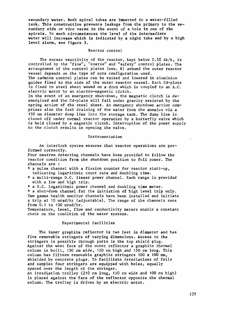
secundary water. Both spiral tubes are immersed in a water-filledtank. This construction prevents leakage from the primary to the se-cundary side or vice versa in the event of a hole in one of thespirals. In such circumstances the level of the intermediatewater will increase which is indicated by a sight tube and by a highlevel alarm, see figure 3.
Reactor control
The excess reactivity of the reactor, kept below 0.5% Ak/k, iscontrolled by the "fine", "coarse" and "safety" control plates. Thearrangement of the control plates (max. 6) around the outer reactorvessel depends on the type of core configuration used.The cadmium control plates can be raised and lowered in aluminiumguides fixed to the side of the outer reactor vessel. Each Cd-plateis fixed to steel sheet wound on a drum which is coupled to an A.C.electric motor by an electro-magnetic clutch.In the event of an emergency shut-down, the magnetic clutch is de-energized and the Cd-plate will fall under gravity assisted by thespring action of the steel sheet. An emergency shutdown action com-prises also the fast draining of the water from the annulus via a150 mm diameter dump line into the storage tank. The dump line is-closed off under normal reactor operation by a butterfly valve whichis held closed by a magnetic clutch. Interruption of the power supplyto the clutch results in opening the valve.
Instrumentation
An interlock system ensures that reactor operations are per-formed correctly.Four neutron detecting channels have been provided to follow thereactor condition from the shutdown position to full power. Thechannels are :* a pulse channel with a fission counter for reactor start-up,
indicating logarithmic count rate and doubling time.* a multi-range D.C. linear power channel. Each range is providedwith a low and high trip.
* a D.C. logarithmic power channel and doubling time meter.* a shut-down channel for the initiation of high level trip only.Two gamma health monitor channels have been installed and initiatea trip at 10 mrad/hr (adjustable). The range of the channels runsfrom 0.1 to 100 mrad/hr.Temperature, level, flow and conductivity meters enable a constantcheck on the condition of the water systems.
Experimental facilities
The inner graphite reflector is two feet in diameter and hasfive removable stringers of varying dimensions. Access to thestringers is possible through ports in the top shield plug.Against the west face of the outer reflector a graphite thermalcolumn is built, 150 cm wide, 120 cm high and 150 cm long. Thiscolumn has fifteen removable graphite stringers 100 x 100 mm,shielded by concrete plugs. To facilitate irradiations of foilsand samples four stringers are equipped with holes, equallyspaced over the length of the stringer.An irradiation trolley (210 cm long, 150 cm wide and 100 cm high)is placed against the face of the reflector opposite the thermalcolumn. The trolley is driven by an electric motor.
125

Two horizontal holes 100 x 100 mm, provided with removable shieldplugs, penetrate the shield and the reflector at the actual latticemidplane. These beamholes are at right angles to the thermal columnand the irradiation trolley and extend to the outer reactor vessel.Space and structural strength is provided for exponential experimentson top of the core region. Removal of the upper shield plug leavesa five foot square distributed neutron source which may be shapedby addition of a graphite pedestal. Performance of such experimentstemporarily precludes any access to the core.
COST
The cost of the complete reactor facility installed in a semi-airtight hall of the E. Fermi Laboratory, excluding this hall andfuel, in 1960 was about $ 170.000 ($ rate April 1985). At the startof the reactor the fuel has been ordered on a renting base. Later onthe fuel was purchased.
The yearly operating costs, 1985, are $ 110.000. This costs includethe salary of the reactor operating staff and maintenance etc. butexclude the infrastructure- and overhead costs of the research in-stitute.The operating staff consists of a manager (50%), a supervisor andtwo operators, all fully licensed according the obligations of thenational safety regulations. To operate the reactor a minimum staffof two licensed operators is required.
REFERENCES
1. J.'A. Goedkoop and J. Pelser, Programming and utilization ofResearch Reactors, Vienna October 1961, P. 431-436, AcademicPress London/New York.
2. J. Coehoorn and J.H.B. Madsen, The Low Flux Reactor, Atoom-energie, Vol. 4-nr. 11 (November 1962).
3. Directory of Nuclear Reactors, IAEA, 1964, Vol. V.
4. J.A.G. Davids, A.P.J. Mos and A. de Oude, Fast-neutron facilityfor biological exposures in an Argonaut reactor : Design, tissuedosimetry and neutron spectrometry, Phys. Med. Biol., Vol. 14,nr. 4, p. 573-584 (February 1969).
5. J.A.G. Davids, Application of a fast-neutron facility in anArgonaut reactor for radiobiological research p. 27-40 in :"Radiobiological applications of neutron irradiations",IAEA-STI/PUB/325, Vienna 1972.
6. J.J. Veenema, D. Mesman and H.P. Leeflang, Neutron radiographyexperiences at the Low Flux Reactor p. 127-133 in : "World con-ference on neutron radiography", San Diego USA (December 1981),D. Reidel Publ. Co.
7. F.M. de Meulemeester, Operation and utilization of the Argonauttype Low Flux Reactor, p. 188-194 in proceedings of the Inter-national Symposium on the Use and Development of Low and MediumFlux Reactors, Massachusetts Institute of Technology, CambridgeMassachusetts USA, October 1983, Karl Thiemig-Minchen Publ.
126

SOME EXPERIENCE WITH OPERATIONAND USE OF A TRAINING REACTOR
F. LEVAI, G. CSOMNuclear Training Reactor,Technical University of Budapest,Budapest, Hungary
Abstract
This reactor was originally designed for 10kW and upgraded to 100kwin 1980. It is a pool-type reactor with a primary and secondary coolingcircuit utilizing BK-10 cylindrical rod fuel of U02 with enrichment of20 percent. This design is similar to other reactors operating up to2MW. The experimental facilities include five horizontal beam tubes, alarge tunnel useable as a thermal column, vertical in-core and reflectorirradiation positions and a pneumatic transfer ystem. The staff for thetraining center consists of about 50 people responsible for theoperation, maintenance, repair and utilization of the reactor. Thereactor is used primarily for training university and outside personnelbut is also used for research, non-destructive testing, neutronradiography and development of nuclear radiation instrumentation. Itslow neutron flux, however, does not permit neutron diffraction orscattering activities.
History
The first nuclear research reactor in Hungary went the
first time critical in 1959 with an initial power of 2 MW
which was later increased to 5 MW. Following this a series
of zero power critical facilities have been constructed and
used. Based on experience gained with these facilities a fully
hungarian-made university reactor has been designed and
constructed. Construction work began in 1967 and the reactor
went first critical in June 1971 with a maximum power of
10 kW, which was increased in 1980 by an order of magnitude
to 100 kW. The reactor is located in a University Campus.
The main objectives for establishing a Nuclear Training
Center with a reactor were as follws:
- Providing nuclear education at university level
in a very broad range of nuclear sciences for all
hungarian universities;
127

- Promotion of the formation of an overall nuclear
scientific and technical infrastructure within the
country in order to prepare for a nuclear power
programme.
I. Description of the reactor
1. The reactor block arrangement
The reactor is located in a University Campus. The
reactor block is in the centre of the reactor building
surrounded by laboratories /fig.l/. It is a pool type above
ground arrangement with desalinated water moderator and
coolant /fig. 1 and 2/. This gives an easy access to and
manipulations inside the core area which are important for
training purposes. The shielding is made of standard and
heavy concrete. The level of the beam tubes is below the
ground.
1- Reactor hall; 2 - Reactor block; 3 - Horizontal channel; 4 - Ordinaryconcrete
radiation shielding; 5 - Heavy-concrete radiation /biological/ shield; 6-Reactor tank;
7 - Experimental shaft; 8- Plexiglass bellcover; 9 - Vertical channels; 10 - Safety
and control rods; 11 - Active zone: 12 - Water tank: 13 - Radiation tunnel. 14 - Heavy
concrete shielding door; 15 - Basement; 16 - Mouting floor; 17 - Inner circular gallery.
Fig.i.
Cross section of the reactor building
128
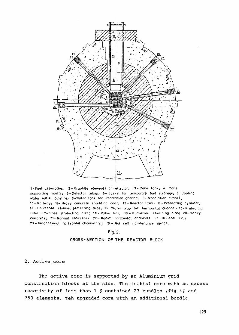
1-Fuel assemblies; 2-Graphite elements of reflector; 3- Zone tank; 4 Zonesupporting mantle; 5-Detector tubesj 6- Basket for temporary fuel stroroge; 7 Coolingwater outlet pipelines 8-Water tank for irradiation channelj 9-1rradiation tunnel;10-Railwayj 11- Heavy concrete shielding door; 12-Reactor tank; 13-Protecting cylinderj14-Horizontal channel protecting tube; 15-Water trap for horizontal channeti 16-Protectingtube; 17-Steel protecting disc; 18-Valve box; 19 - Radiation shielding ribs; 20-Heavyconcrete; 21- Normal concrete, 22-Radial horizontal channels I. 1. II. and IV./23-Tangentional horizontal channel V.j 24- Hot cell maintenance space.
Fig. 2.
CROSS-SECTION OF THE REACTOR BLOCK
2. Active core
The active core is supported by an Aluminium grid
construction blocks at the side. The initial core with an excess
reactivity of less than 1 $ contained 23 bundles /fig.4/ and
353 elements. Teh upgraded core with an additional bundle
129

II1I~
iiiii1ii1
1
1
1
11i11
1
il
111111
1 1
1 i
1
La,
' ' '.'','. .' " " / '.' 1- I^ ^ 5
^1^' .^.\ ;yg
^^*^°w
^*:
^Gl^ :*' , o il
1-Reactor tank', 2-Graphite reflector elements; 3- Fuel element assemblies; 4-Safety and control rods;5-Detector tubes; 6- Zone tank, 7-Zone holder mantle; -ODiffusor; 9- njectors; 10- Divisionchamber; 11-Cooling water inlet pipeline, 12-Zone holder ribs; 13- Draining pipeline 14- Cooling wateroutlet pipeline; 15-Filling pipeline for the water trap of horizontal channel) 16 - Tunnel and pipeline forleakage water; 17-Protecting cylinder; 18-Perforated plate; 19-lrradiation tunnel; 20 Water tank ofIrradiation tunneti 21-Vertical channels of Irradiation tunnel; 22-Heavy-concrete radiation (biological)shieldj 23-Normal-concrete radiation shield; 24 - Radiation shielding girth and columns i 25-Heavyconcrete shielding door; 26-Heavy-concrete protecting plugs; 27-Vertical irradiation channels2- Supports ol vertical irradiation channels; 29-Supporting bridge for control rods; 30 Centering andradiation shielding wedges; 31- Reactor flat top cover; 32- Reactor double cover1 33 PleKtglassbetl-coverj 34-Servomechanisms of control and safety rods; 35-Cable duct; 36 Packing-glandbushlngsj 37-Suction air duct; 38- Reactor-top railing.
Fig.3.
LONGITUDIONAL SECTION OF THE REACTOR BLOCK
130
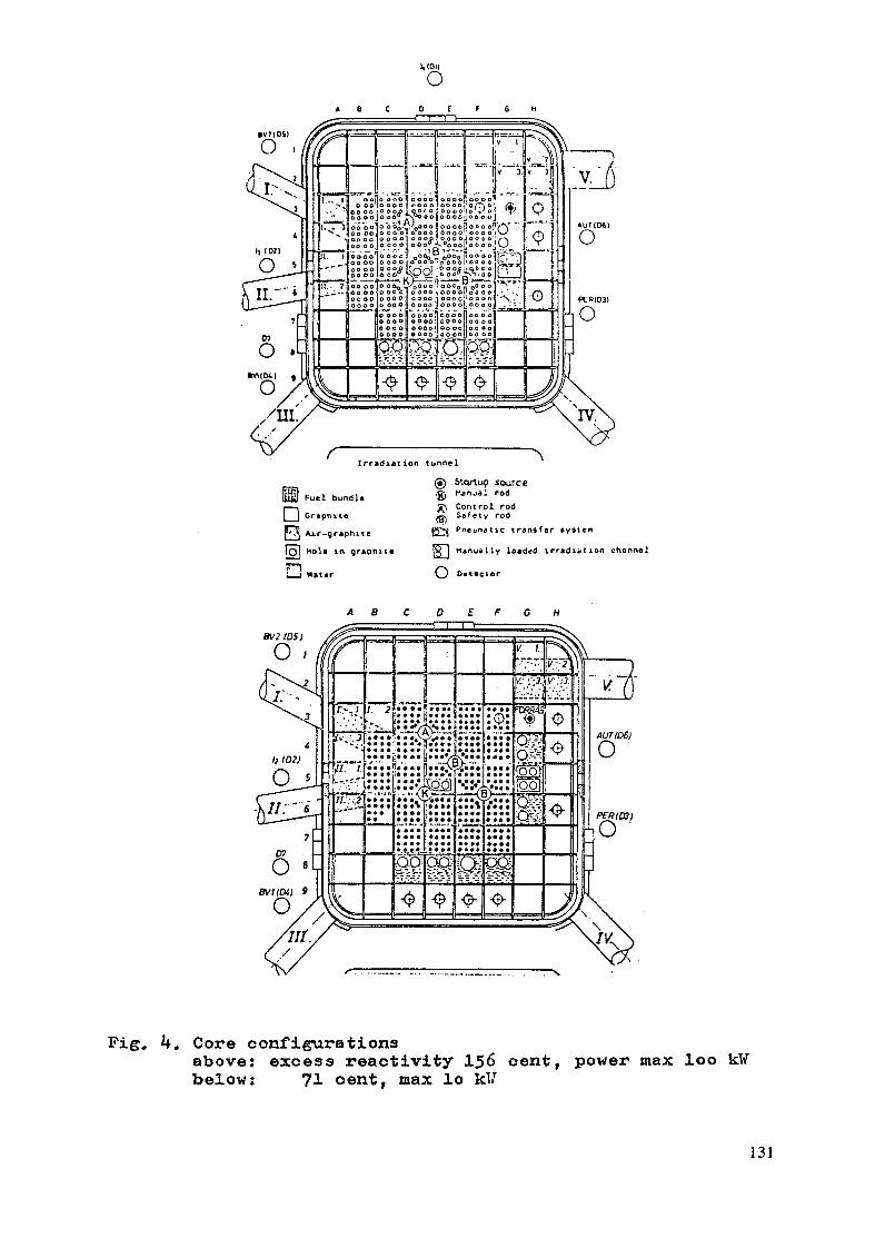
I, t(o
0A B C 0 E F G H
»v?(o$I
0
23 I
00,.
VI h
/xII
'001 & v 3 vo o o
I I_- ^-. ... . , _ -, _ -.'
t, I o W-6 -°°jDo000 00 001 0000 . O OOO.OOlO'i 00 I 'T' n
0o oo o ooo oo ooooooo
=- I==loooo =00o 0 0 o °°o' O l i'
11 .ooooloo ooo ooo000 ' :1
I - o000000l oo00 O O 0000 001 00 :
* .28ool o l; nl w
u o lo oooo oonoo oo.looo ooo r ' Pr 1
fQ IQ -e - .0. Q- .-j
lt lr 7-< n\a 00 Tr r 0000 000 00000000 ~~~lTV.
rIrradiation tunnel
S Fuel bundle
] Graphite
E Air-graphite
Ti hole in graphite
E]" Water
( Sicotup sourcenManal rod
, Control rod) Safety rod
E Pneumatic transfer systen
E nanually loaded irradiation channal
O D0tector
BV2 (DS)
01
0,
7
0 8Bv (D4) 9
0/
A
68 C 0 E F 0 H
_E=^=?1 wrtt - i Y . iS\
I 1V. I _\\
I' - -
|,* 3 f'-'- - 7'. -. '* M | A .
' ·.' | j * * ' .* **e D *
" ' , ;'" i^;^, ' i.;' 2..;,-, ..::,«,K.. . .'.«* */*-. .;I--
. '- *** * O **-* ** * *t@ -0 1111 - I* ' * -i * . . *- ; I*! *I . *I R -
- e - I - !
'v
AUr (6)
0
--- 1_.rI 11rW
Ivngu0
//"\
Fig. 4. Core configurationsabove: excess reactivity 156 cent, power max loo kWbelow: 71 cent, max lo kU
131

t-
Li
0
0.
4,
4V
C,
cI
x
tU
C>
0
'>
U
Xxen
70 o ___.60 e GO o o o_°°- so 1 - 1 0 lloo, oO - o50 0- 0 o^ 00030 O ob ° ° °-o-30 ___ _ _
Fig. Sb
(
2C
ICCcI-i 1 1-
I1971 72 73 74 75 76 year -
1978 79 80 81 82 83 year
132

/total 369 elements/ had the reactivity balance as follows
/September 1981/:
- Poisoning /due to 36 hours operation/ 66 cent
- Loss due to power effect 37 cent
- for irradiation 30 cent
- for control 23,3 cent
cold clean excess reactivity 156.3 cent
The neutron flux distribution in the core is highly
distorted. Neutron traps ensure peaks of neutron flux in
locations of irradiation positions /fig.6/. The peak thermal16 "2 -1
flux is 2,7.10 m s , the figure of peak flux per unit
power being thus 2,7.1011 n/m2sW a value ranging among top
figures of similar reactors.
3. Fuel
The fuel is of soviet made type EK-10 cylindrical rod
shaped with an outer diameter of 10 mm and 1,5 mm thickness
Aluminium cladding. The U02 fuel is enriched to 10 %, and
is assembled in a 4 by 4 rectangular array forming a bundle,
This is a standard assembly designed for VVRSZ type research
reactors operating at 2 MW power level.
4. Fuel consumption
A very important advantage of a small reactor is its low
fuel consumption and practically no need for refuelling.
Fuel consumption depends on energy produced and causes a
decrease of available excess reactivity which limits its use
for a particular task and at a value it limits its operation.
The total energy produced yearly by the Training Reactor
before and after the power upgrading can be seen in fig. 5/a
and the resulting measured excess reactivity loss in fig.5/b.
Most of the training uses need low energy operation, research
and service activities need mostly higher power level.
133

5th rO.
: !
·0 -I -
r
0 20 40 60 80
~___~_________' cicumn
Voter Graphie Core Core Waler C-
24 -
22 -F ost
/ 'V~luxy20-
5i I . 6
Neutron distributions inside Therme.
134
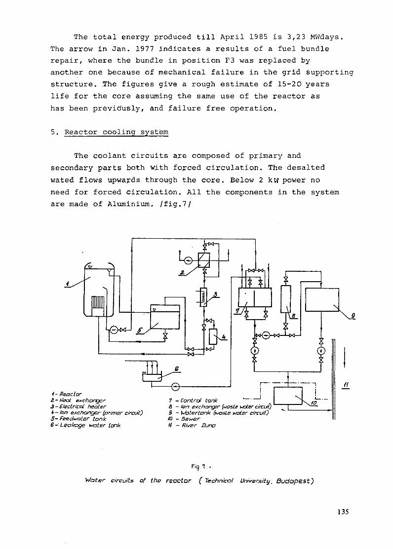
The total energy produced till April 1985 is 3,23 MWdays.
The arrow in Jan. 1977 indicates a results of a fuel bundle
repair, where the bundle in position F3 was replaced by
another one because of mechanical failure in the grid supporting
structure. The figures give a rough estimate of 15-20 years
life for the core assuming the same use of the reactor as
has been previdusly, and failure free operation.
5. Reactor cooling system
The coolant circuits are composed of primary and
secondary parts both with forced circulation. The desalted
wated flows upwards through the core. Below 2 kw power no
need for forced circulation. All the components in the system
are made of Aluminium. /fig.7/
4- Reactor2 - eal exchonger3- Electrril heater4- Ion exchanger (prirner circui)5- Feedwoter tank6- Leakage water tonk
7 - Control tank8 - Ion exchanger (waste water circuit)9 - /otertonk (waste water circuit)
10 - SewerH - River Dunr
Fig '. .
Water circuits of the reactor ( Technical University, Budopest)
135

6. Control and protection system
The control and protection system shematic can be seen
in fig. 8. 6 neutron channels 2 safety, 1 shim and 1 fine
control rods are use. The present instrumentation was the
prototype of the new hungarian product and has been used
since 1979 giving excellent performance and reliability figures.
level trip
G_< T, tripL Le | 2x 2 startup channel
level trip ANDfissioncliambers sr
T2X trlp
CIc C Nscram 2 safety channel
CIC cz--level trip
T2x tripCIC Ce scram 1 logarithmic DC channel
demand level
CIC 1 DC Linear channelC " < W_---- ~ ~ for automatic control
Aut. Manual Iu/d
Rods - u/d up/down
JId
soufinrc e nuclear ramposionters
0'
I~~~~ ~~~oscram perto
Fig. B. Control and safety system
shematic, 100 kW University Reactor
„ scram @sous - u/d up/docn
fafety and safety s
shematic, 100 kM University Reactor
136

The hierarchy and sophistication of the system have
been demanded by safety level necessary for a reactor in a
university campus /14, 22, 23/.
7. Experimental facilities
- Beam tubes and tunnel
Five horizontal beam tubes and a large area tunnel are
connected to the core. Each has different connections and
different neutron spectra. The tunnel offers high flexibility
in its utilisation. The distance between the inner surface
ant the graphite block is only 9 cm. Inthis gap different
couplings /air, water, metal e.t.c./ can be realized inside
the vessel.
If the whole space inside the tunnel is filled with graphite
block, it can be used as a thermal column.
- Manually loaded irratiation channels
In core. and in-reflector positions there are a variety of
locations /in water or in graphite/ for irradiation by a
thermal flux value of 12,6.10 n/m s.
- Pneumatic transfer system
In core position /D5/ and 2 in reflector positions /G5/
there are locations for irradiation by a fast pneumatic
transfer system. The layout of the transfer system as well
as the interconnections between laboratories can be seen in
fig.9.
- Hot cell
A cell consisting of two compartments is provided for manipulating
radioactive materials. The irradiated sample. from the manually
loaded channels is sent through a tube in the shielding by
gravity into the hot cell. The material processed can be
transported to the radiochemical laboratory either by means
of a pneumatic transfer system or in a shielded container
placed under the cell.
137

EXPLANTATION
3 7/7 - Track tube
\ X ff.PP 1It^ 73 1 - active core
C^^IFO X ~ f li\2 - polypropilene
track tubes
3 - switch
L1^ ./^ \^^y '"I 4 - instrument room
5 - departure /arrival
'f2 RTstation// // /y 6 - radiochemical lab.
/ 2i D(/ //y I^ /E/3 |- low-background
I L2 / III measuring points
7 - hood
11O~~~ I if 0 // // ] ji '29 - manipulator chamber
Fig. 9
Layout of pneumatic transfer system
8. Laboratories and staff
The reactor is a part of a Nuclear Training Center.
There are laboratories for radiation protection, radiation
chemistry, reactor physics, nuclear electronics and computer
center. Hot cells are also provided. Two sample transfer
systems ensure connection between the reactor, laboratories
and hot cells.
The staff consists of some 50 persons. This includes 20
scientific research workers namely 7 electronic and electrical
engineers, 6 physicists, 4 mechanical engineers, 2 chemists,
1 geologist.
II. Utilization of the reactor
Basic requirements are summarized as follows:
- a/ Nuclear power programme requirements
The fist hungarian nuclear power station has been
operating since 1982. More units are under construction.
138

Fig. 10.
Layout of manipulator chamber /hot cell/
The requirements are summarized as follows:
- programme oriented supporting activities
comparising research and development;
- participation in nuclear manpower development.
- b/ University requirements
- providing nuclear education at university level
by offering special courses, postgraduate training,
degree work and special laboratory exercises
for all hungarian universities and for foreign
partners which are in cooperation with Hungary.
This large variety of partners shows that a broad
range of sciences has to be dealt with;
- research directly sponsored by the nuclear power
projects /mainly on contract base/;
- assisting industry adopting nuclear technology
139

- Training exercises.
Bread scope of research which is possible and the
ability to support simultaneously many experiments
from different branches of sciences and engineering
are striking features of a research reactor of
even moderate size. A series of experimental
exercises have been developed which are instructive
and pleasent for the fields of interests. They
are developed in the fields of neutron physics
reactor physics and many other fields.
Sample training exercises are given in this paper.
A detailed description of laboratory experiments
and their required laboratories and equipments can
be found in /9/ and /10/.
Sample training exercises provided by the 100 kW reactor at
the Technical University, Budapest
1. Digital computer simulation training.
Using a sumulator with full scale control desk provides
kinetic simulations, study dynamics and feedback effects,
operator training e.t.c.
2. Reactor operation training.
Using the reactor for daily operations and for all types
of manipulations.
3. Control rod calibration by doubling time method.
4. Control rod calibration by subcritical counting.
5. Determination of control rod worth by use of pulsed neutron
source.
Using a neutron burst injected into the reactor by a sealed
tube neutron generator and measuring the response for
determining reactivity.
6. Determination of the reactivity worth function for neutron
absorbers.
A Cd absorber is inserted into the reactor and the resulting
reactivity is measured in different positions.
140

7. Determination of void coefficient of reactivity.
Reactivity effect of an air void inserted into the core is
determined as a function of position.
8. Critical and subcritical experiments.
An approach to criticality experiment and measuring excess
reactivity are performed.
9. Determination of delayed neutron parameters and Uranium content.
Uranium sample is irradiated in the core by the rabbit system
and emitted neutrons are measured by a time analyser.
10. Thermal neutron flux measurement in the core with the help
of an Dy wire, axial flux distribution of the core is detaemined.
11. Radiation protection and shielding measurements in a neutron-
gamma field.
Measuring neutron-gamma dose rates at the beam tubes and behind
shielding as a function of reactor power are performed.
12. Measurements with thermoluminexcent dosimeters.
Practicing TLD technique by dose measurements is realized.
13. Measurement of surface contamination decontamination.
/A decontamination practice/
14. Rod-drop technique
Large values of reactivity are measured by analysing
neutron density decay after shutdown,
15. Determination of neutron dose intensity in the core of
the reactor on the basis of neutron spectrum measurement.
A practice on neutron spectrum measurement by foil
activation technique.
16. Thermal neutron spectrum measurement at the beam tube.
/Chopper type time of flight technique/.
17. Measurement of the thermal neutron flux by thermoluminescent
detectors.
/Flux measurement at a beam tube by TLD/
141

18. Measurement of thermal neutron diffusion length in grafite.
Neutron flux distribution is determined by foil activation
in the thermal column.
19. Laboratory practice on neutron radiography.
Nonradioactive and irradiated objects are radiographed
using different techniques at beam tubes.
20. Rapid determination of Vanadium and Manganese content
in steel by activation analysis.
Irradiation is in the core by the rabbit system, for
evaluation a GeLi detector with a multichannel analyser
and reference sample are used.
21. Multielement analysis of biological materials.
A practice on thermal and epithermal neutron activation
and on comparator technique.
22. Determination of some gamma-emitting radioactive isotopes
enriched in the water circuits of nuclear power stations
by means of gamma spectrometry.
/A model experiment/.
Selected research topics
1. Neutron spectroscopy
Numerous tasks in the research program of the Institute
necessiated the knowledge of the neutron field in the core
and at beam tubes. As in case of nuclear reactors one meets
the problem of mixed /neutron and gamma/ fields the activation
neutron spectrometry can advantageously be used. The activation
detectors are insensitive to gamma radiation, as a result of
discrimination between the two kinds of radiation lneutronsand
gammas/ can easily be solved by this method. Furthermore, due to
the small size of these detectors the perturbation effects
in the neutron field can be decreased negligible small. For
this reason activation neutron spectrometry - in special cases
combined with other methods - is preferably used in our
Institute for neutron field studies. The neutron flux density
142

in the core /and e.g. in the irradiation tunnel of the
reactor/ at 100 kW reactor power is high enough to get a
measurable response of these detectors.
Neutron spectrum determination by multiple foil activation
method
A series of activation detectors /in form of thin foils
or wires/ is irradiatied in the neutron field to be studied
and their activity is measured. Special "unfolding computer
codes are then used to elaborate the neutron flux density
spectrum from these data.In practice the number of energy
groups spreads from 50 to 640, and the number of detectors
from 10 to 30 so the freedom of the system is rather high,
the solution is not unique and the neutron flux density
spectrum cannot be derived from these data without a priory
assumption of the initial neutron spectrum based on all physical
informations available in the given case.
Neutron energy [MeVj
Fig. U{.
Neutron spectrum in the core position D5 of
BTU's nuclear reactor at 1OOkW power.
143

Lots of neutron spectrum unfolding codes based on different
phylosophies have been used so far in the literature for
solution of this problem. At our institute the unfolding
codes SAND II, FRSP and SANDBP /12/ have been used.
Instrumentation
For determining the activity of the detectors instruments
generally used in gamma spectrometry leg. also for activation
analysis/ are applied: Ge or Ge/Li/ semiconductor detector
,+ multichannel pulse height analyser.
For unfolding the neutron spectrum a computer with a core
size of minimum 256 Kbytes /preferably 512 Kbytes/ is
needed.
Other methods used for neutron spectrum determination
As the neutron flux density at the horisontal beam tubes
is about 5 orders of magnitude lower than that one in the
core, only a limited number of activation detectors can
give a measurable response in this neutron field. In radiation
shielding experiments-carried out in the irradiation tunnel
of the reactor - behind thick shielding walls one meets the
same problem.
3Then the activation detectors are combined with BF 3 or 3He
detectors, furthermore, neutron spectrometry using proton
recoil detectors and SilLi/ semiconductor detectors /13/ are
applied.
Application of the results
The results of neutron spectrometry have been widely used
in the Institute's research program joining the national
and international /IAEA and COMECON/ nuclear program:
- Radiation shielding experiments - results used at the
first Hungarian nuclear power plant.
144

- Development of new neutron spectrum unfolding methods,
investigations in different neutron fields - results
used in-the national /and COMEOON/ surveillance program
for nuclear power plant's preassure vessel.
- International activity: REAL-80 interlaboratory exercise
organized by IAEA for international intercomparison of
neutron spectrum unfolding codes and spectrum /12/
charactersitic integral parameters for radiation damage
investigations; results used in the national and international
surveillance program of reactor preasure vessels.
-Results of neutron spectrometry are also used in the
field of health physics studies.
2. Use of the neutron beam tubes for nondestructive testing
Knowledge of the structure of a material is necessary
to determine its behavior under different excitations.
Neutron beam provide a probe that may be used to study of
materials.
First a distinction is made between microscopic and
macroscopic diagnostic techniques. Under microscopic diagnostic
are classified those techniques where monoenergetic neutrons
are used and provide information on the atomic scale. For
macroscopic diagnostic a broad spectrum of radiation is
used which enter the material to be studied and the emerging
radiation scattered or uncollided are analysed thus giving
information on the bulk or gross material feature under both
static and dynamic conditions.
All the research work which need monochomator for selecting
nearly a monoenergetic neutron flux are beyond the capabi-
lity of such a small reactor, therefore only macroscopic
diagnostic techniques are studied. The following specific
areas will be mentioned:
- neutron radiography
- tomography.
145

Neutron radiographic inspection of irradiated materials
After materials have been irradiated, the difficulties
involved in precision measurement by "normal" methods are
much increased and alternative methods, such as measuring
from a neutron - radiograph image, become attractive.
This is especially so when the object is undergoing a
lengthy irradiation, and periodic dimensional checks are
required in course of the experiment. The rapid advance of
neutron radiography in the field of monitoring radioactive
materials is due one hand to the fact that heavy materials
are relatively transparent to neutrons, and on the other,
to the intensitivity of detectors to the gamma background
noise emitted by the objects under examination.
The unique feature of neutron radiography for testing
irradiated fuel: the ability to both penetrate uranium235 2.38
and to distinguish between the isotopes 2U and 2U.
Uses of fuel radiographs are nemerous but they can
be summarized as checks for correct assembly /pre-irradiation/
and for changes and damage /post-irradiation/. Almost all
fuel applications to date have been qualitative.
The radioactive nature of irradiated fuel elements
and their high absorption for thermal neutrons has led naturally
to the use of indirect and track etch neutron radiography,
and using epithermal /Cd filtered/ beam with In detector.
146

Neutron beam tubes used for neutron radiography
L /D thermal neutron exposure typicalflux n/m s method exposureat the object time
/100 kW/
Beam No 5 25 3.1011 Dy, In
Beam No 3 40 1,45.1011 Dy, In
Beam No 3 with Bi filter 40 4,8.1010 Dy 40 min /at
10 kW/Gd 10 min /at
10 kW/In 1 hr /at
100 kW/
Beam No2 40 thermal.
3,34.10 In 1 hr /at 100
fast 1 Cd filt- kW/1,5.10 ered/
Tomography
A radiograph is a two dimentional projection of a three
dimensional object. To obtain information about the spatial
locations of different structures within the object a number
of radiographs can be taken from different angles. Modern
structures are, however, becoming more and more complex
and the evaluation of a three dimensional object by a two
dimensional shadow image is nearly impossible. This
difficulty has been solved by a technique called "Computed
Tomography". A tomogram is a picture of a slice. The image
is reconstructed as if it had been possible to cut and
view the object over a plane. A full, three dimensional
picture can be obtained by stacking a sequence of such
layers. For the reconstruction a series of radiographs are
taken at different angles and a section image is calculated.
The more the angles, the more exact the reconstruction is
/6,7/. The present work aimed at taking neuutron radiographs
with Cd filtered beam using In detector at several angles
of a fuel bundle and reconstructing the interior structure
for nondestructive testing and safeguard.
147

3. Neutron dosimetry research with TLD
Neutron dose rate in and around a small reactor can be
conveniently measured by a specially developed technique.In this
method LiF and Ca 2 TL. detectors are used together. LiF
responses to both neutrons and gammas, while CaF2 responses
to only gammas, and the difference gives neutron dose within
a few percent accuracy.
This method can be used for in core measurements up to
about 1 kW power, and dose rates at the beam tubes can be
determined in the whole power range of the reactor. /18/
4. Instrumentation development
Reactor beams and low level flux areas are very convenient
for feasibility and life testing of nuclear radiation
instrumentation.New concepts for high radiation level
instruments, serviceability, operational problems can be
tested near the core areas. In cooperation with other
hungarian institutes and factories an intensive continuous
nuclear instrumentation development program is being carried
out. Some of the moduls of a new reactor instrumentation
system are developed by the Technical University, and the
whole system is tested and calibrated at the small reactor.
- Research reactor instrumentation
A demand made by a renewal and upgrading program initiated
development in reactor instrumentation /22, 23/. Some of the
moduls of the new reactor instrumentation are developed
by the staff and the whole system is tested and calibrated at
the small reactor.
- Educational nuclear instrumentation
Some special instruments have been developed for reactor
laboratory exercises and training purposes like a small
computer based research reactor training simulator, which
148

is suitable for operational training, kinetic, temperature
feedback and poisoning studies with arbitrary time scaling.
/9/ Automatic measurement of activity distribution along the
length of a Dysposium wire irradiated in the core is another
example /9/.
- Nuclear power instnmentation
Skills and experience gained with reactor instrumentation
activity have resulted in development of some special
instrumentation for power reactor like: continuous measurement
of innert gas in effluents, boron content in primary circuit
by neutron transmission. Personal and area radiation monitoring
instrumentation are other areas of development work in
cooperation with other institutes /3/.
- Industrial isotope technique
Several instruments have been developed using nuclear
technique for industrial application, among these are:
measuring ash content and humidity in coal, density of
concrete /3/ e.t.c.
5. Neutron activation analysis
The considerable advances made in the last decade in
gamma ray spectrometry equipment have accelerated the
development of reactor neutron activation analysis techniques
and applications in many fields. Increased attention is being
devoted to the use of purely instrumental neutron activation
analysis techniques, using Ge/Li/ gamma ray spectrometry.
In this respect the reactor may be regarded as an
instrument that enables the chemist to expose samples to
a desired neutron flux for a desired length of time ]usually
anywhere from seconds to hours/, and it is preffered that
the samples not be exposed to appreciable temperatures, gamma
ray dose during activations.
149

Samples to be irradiated are sent to the in core or in
reflector areas either by the pneumtic transfer system or
by a manually operated loading system /into vertical irradiation
'channels/.
After irradiation samples are sent to the radiochemical
laboratories either directly by the pneumatic transfer
system, or through the hot cell by another transport system.
Simultaneous irradiation of the samples and a standard
of known mass will give the mass of the target isotope from
the ratio of activaties, provided the effective flux is the same
in both cases. In accurate comparisons this equality of
fluxus raises the problem of perturbation of the flux by
the samples; materials with high thermal neutron cross sections
or strong resonancies require considerable care from this
point of view. The production of the active isotope by fast
neutron bombardment of different elements in the sample may
also lead to the need for correction or for separate measurement
of their contribution by irradiation with the sample
shielded from thermal neutrons by cadmium.
For large series of measurement acceptable accuracy can be
obtained by using comparator technique, where only one element
/comparator/ is used for calculating concentrations. For some
cases activation by epithermal neutrons ensures the requested
selectivity. For unknown samples usually three irradiation
are taken /15 min, 1 hs, 12 hrs/ and measurements are made
after allowing different delay times.
As a service activity the following types of samples and elements
are analysed successfully by using the reactor.
- Environmental pollution studies /5/
Elements measured are: Na, Mg, Al, Clf K, Ca, Sc, Ti, V,
Cr, Mn, Fe, Co, Zn, Ag, Se, Bi, Rb, Sb, Cs, Ba, La, Ce,
Sm, Eu, Tb, Lu, Hf,Ta, Au, Th
- Geological samples /20 1
Elements measured are: Sc, Fe, Co, La, Ce, Nd, Sm, Cu,
Tb, Tm, Yb, Lu, Hf, Ta, Th
150

- Archeological /ceramic/ samples /21/
Elements measured are: Sc, Cr, Fe, Cof Rb, Cs., La, Ce,
Eu, Yb, Ln, Hf, U,
Problems and limitations of activation analysis related to
university reactor
The main limitations in activation analysis at a small
university reactor are imposed by
- Training program requirement.
Activation analysis needs the reactor running at its maximum
power level for the whole irradiation time which is a
conflicting requirement with many of the training exercises
demanding low power level.
- Flux level
The only limitation of a low power level is the lack of
sensitivity.
- Economical problems
In many cases it is much more economical and practical to
irradiate samples for a few hours at another 5 MW reactor,
than using small reactor for a whole day irradiation.
6. Nuclear Fuel cycle study
Theoretical analysis of the nuclear fuel cycle is justified
by long term energy policy /3/.
References
1. Gy. Csom and F. Levai: The nuclear training reactor
of the Budapest Technical University,TR Report
August 1983
2. F.L6vai and f.Zsolnay: A low power training reactor
as an instrument for basic research. IAEA-Teehdoc-320
151

3. Papers from the Nuclear Training Reactor
Special issue of Periodica Polytechnica Electrical
Engineering Vol 26. Nos 1-2 /1982/
4. t.Zsolnay and E. Szondi: Neutron spectrum determination
by multiple foil activation method:in ref No 3
5. J. B6rczi, G.Kebmley, Zs. Molnar,T. Varkonyi: Detection
of emission sources on the basis of the trace element
composition of aerosols: in ref. no 3
6. F.L6vai: Computed tomographic methods for nuclear
fuel characterization and safeguards in ref. no 3
7. F. Levai: Use of radiographs for section imaging
Periodica Polytechnica,Mechanical Engineering
Vol 28 Nol /1984/
8. E. Zsolnay, E. Szondi: Experiences with neutron
spectrum unfolding codes in different neutron spectra
Proc. 4th ASTM-EURATOM Symposium on Reactor dosimetry,
NBS Gaithersburg, Maryland NUREC/CP-0029, March /1982/
9. Ed.G. Xeomley: Laboratory training menual on the
practice and use of research reactors.IAEA Training
Manual
10. Ed. F. Levai: Nuclear manpower development
a./ basic installations
b./ laboratories and their instrumentation
c./ educational programmes
Rep.Industrialexport prepared by Bp Technical University
11. Gy. Csom: Nuclear Training reactor of the Technical
University;in ref no 3
12. E. Szondi and £. Zsolnay: SANDBP, an iterative neutron
spectrum unfolding code
BME-TR-RES-2/81 /1981/
152

13. S. Desi: Fast neutron flux measurement and spectroscopy
using silicon detectors
Nuclear Instruments and Methods 140/1977/ 467
14. Ed. Gy. Csom: Safety report for upgrading of the Bp
Technical University Training Reactor:BTU Report /1980/
15. Operational instructions of the Bp. Technical University
Training reactor
16. Operational rules of the Bp. Technical University Training
reactor
17. Gy.Csom: Technology of research reactors:BTU report
18. E. Vi.ragh: Messung der Flussdichte thermisher Nuetronen6
und der Gammadosisleistung mit LiF und CaF2.Mn- TLD
an Reaktoren Kernenergie 26/1984/
19. F. Levai: Reactor fuel characterization with section
imaging technique
Final Report,IAEA Research Contract No 2467 /1983/
20. J. Berczi: Neutron activation analysis of geological
samples /in hungarian/. Scientific meeting held in
Budapest Technical Univ. March 1983
Section technical physics and nuclear technique
21. M. Balla, O. Gabler: Archeologiai trtesito, 109/1983/7
/in hungarian/
22. F.Levai: Renewal of the Training Reactor of the Technical
University Bp.
IAEA-214 Techdoc, 1978
Research Reactor renewal and upgrading programmes, an
advisory group meeting
153

23. F. Levai: Instrumentation and control system renewal
experience at a small university reactor. IAEA Techdoc,
/in preparation/.
IAEA Consultant meeting on Analysis and Improvement of
Safety related instrumentation and control systems for
research reactors. 1984. sept, Vienna
154

TRAINING ON SILOETTE REACTORAND ASSOCIATED SIMULATORS AT THEGRENOBLE NUCLEAR RESEARCH CENTRE
M. DESTOTCEA - Centre d'etudes nucleaires de Grenoble,Grenoble, France
Abstract
The Siloette is a plate-type pool reactor designed to trainengineers and technicians for positions in the nuclear power programme.The reactor also serves as a mock-up for experiments to be conducted inthe larger Siloe (35MW) and helusine (8MW) reactors. Its beam tubes arealso useful for applications in neutron radiography. The number oftrainees attending courses at this reactor has increased from 165 in 1975to 650 (expected) in 1985. Most courses last from one to three weeks.Training on the Siloette reactor is augmented by a number of nuclearpower plant simulators. Compact simulators for both PWR's and GCR's areinstalled.
1. INTRODUCTION
Thanks to its three reactors : SILOE (35 MW), MELUSINE (8 MW),
and SILOETTE (100 KW), the Reactors Department of the Grenoble Nuclear
Research Centre has gained considerable experience in operation and use
of research and materials testing reactors.
With its large personnel and technical resources, it is
involved in the following wide-ranging fields of activity, at both
national and international levels : irradiation for study and qualif-
ication of materials and fuels from the different types of nuclear
power stations, basic research using neutron beams, safety studies and
tests, test reactor engineering, production of radioisotopes and of
neutron doped silicon, non-destructive neutron radiography tests,...
and training of power station operating personnel.
It is within this general framework that the Grenoble
Reactors Department has created a reactor physics training activity,
based on Siloette, which has been running continuously since 1975 to
cope with the increasing demand resulting from the development of
nuclear power stations.
Its essential aim is initiation in the basic physical
phenomena which determine reactor operation.
155

For this purpose, a fairly comprehensive program of practical
work on reactor (SILOETTE) and nuclear power station simulators
(P.W.R., G.C.R.) is proposed in addition to the lectures and confer-
ences (general and specialized teaching on the reactor operating
principle, kinetics, dynamics and thermics).
This activity is carried out in close collaboration with
Electricite de France, as part of an overall training policy.
This training is mainly intended for engineers and tech-
nicians appointed to responsible positions in power plant operation :
- Engineers, technicians, supervisors and foremen from
Electricite de France,
- Nuclear power industry engineers (Framatome, A.C.B.,
Creusot-Loire, Merlin Gerin,...),
- Nuclear Engineering students from Grenoble National
Polytechnical Institute and from the University.
Substantial efforts are also made to set up similar training
courses for the benefit of engineers, technicians and students from
foreign countries.
Its equipment and the qualification of its personnel also
make Siloette the setting for numerous activities.related to training,
simulation, and reactor safety and operation problems, such as :
- computer assisted teaching
- educational research
- study of the human factors in nuclear power plant operation
- study of the reactor control panel protection systems
- development of simulation software adapted to specific
problems (incidents, accidents ...)
- development of simulation in the "non-nuclear" field.
156

2. THE SILOETTE REACTOR
2.1. Main characteristics and uses
a) General presentation
Siloette is a pool type reactor with a power of 100 kW. The
fuel used is enriched uranium in the form of aluminium clad U-A1
plates. The proportion of uranium in the U-A1 amalgam varies from 22 to
26 % depending on the plates. Control is by means of four Ag-In-Cd fork
type rods.
b) Use
Designed as a nuclear model for the research reactors SILOE and
MELUSINE, installed on the same site, SILOETTE has been used since the
outset for studies and measurements on reactor cores (measuring reac-
tivity, fluxes and spectra, rod calibration, etc...) or on associated
irradiation devices (reactivity effects, flux depression, screening,
etc...). Series of tests on mockups are carried out on request at
SILOETTE, in conjunction with the research teams working at SILOE and
MELUSINE.
The fact that SILOETTE is equipped with neutron beam tubes
enables other applications that do not require large amounts of flux,
such as neutron radiography inspections or certain studies connected with
safety, to be carried out.
Experiments in the reactor core itself can be carried out under
almost ideal conditions : little background noise, no disturbance due
to the environment, unlike what can occur in an experimental reactor
fitted with a large number of devices, very accurate operating periods,
with very quick power rise and fall.
Among the numerous studies related to use of the SILOETTE
reactor, the following are worth mentioning :
- study of a nuclear reactor protection system, for which
prototype qualification was carried out on the Siloette reactor. This
involves a multiprocessor unit with distributed redundancy. The tests
carried out at SILOETTE have enabled progress to be made in defining
architectures (redundancy, task decentralization and hierarchization)
as well as in testing and auto-testing means (intrinsic safety, single
failure criterion).
157

- void fraction measurements. This involves void fraction
measurement qualification by the neutron diffusion method. It is
essential that such measurements be determined to obtain good knowledge
of the void fractions in two-phase flows, in steady or transient con-
ditions (transient in pressurizing phase) which are characteristic, for
example, of the PWR circuits (primary or S.G.).
2.2. Siloette, training reactor
The Siloette pool reactor is particularly suitable for training.
This application has, in fact, now become its main activity. The fis-
sile core remains visible during operation, and handling operations are
very simple and can be directly observed by the trainees. The control
panel is located inside the reactor confinement containing the pool,
which enables all the operations being carried out on the reactor and
the effects of the operating parameters on the neutron monitoring
channels to be observed.
Each practical work session is arranged for a team of five or six
trainees (limit purposely set for reasons of teaching efficiency and
safety conditions inside the reactor).
Several practical work courses are proposed :
- approach to criticality :
. seeking the critical mass by loading fuel elements,
. seeking the critical position of the control rods ;
- flux and power measurements :
. vertical flux distribution with or without disturbances
(display on a multichannel recorder),
. transverse distribution in the mid-height plane in various
media (fuel, water, aluminium...) ;
- reactivity measurements :
. control rod calibration by different methods (period or
reactivity meter),
. fuel element worth measurements,
. reactivity balances.
158

3. ASSOCIATED POWER PLANT SIMULATORS
3.1. Principle
Resulting from internal study needs, simulation was then used
for training students from the University as a complement to the
training which had already been given for very many years using the
Siloette reactor. This complementarity very soon attracted E.D.F.'s
attention for training their own operators. Indeed, the practical work
possibilities of the SILOETTE reactor-compact simulators association
offers a great deal of educational advantages to provide comprehensive
basic training to all those who need to understand the physical phen-
omena governing reactor operation.
The Grenoble Reactors Department designed and used a first mini-
simulator which has now been placed at the disposal of the University,
and then designed and built two compact PWR simulators and a GCR
operation simulator. These training simulators are different from both
the EDF integral representation simulators and the accident sequence
study and analysis simulators.
3.2. PWR PLANT SIMULATORS
a) Principle
These are nuclear power station simulators whose purpose is to
initiate the trainee in understanding the main physical functions that
determine the behaviour of a nuclear boiler. Thus, only the main con-
trol instruments of the simulated power plant necessary for compre-
hension appear on the control desk.
From this viewpoint, the objective aimed for is different from but
complementary to that of a full scope simulator (like those of Bugey -
EDF), the purpose of which is to acquire reflexes for reactor
operation.
b) General presentation
bl] The general architecture is built around three elements
enabling work to be carried out while sitting or standing.
In the upper part of these three elements, all the usual display units
are to be found : recorders, galvanometers, bar graphs, signalling
lamps, alarms, as well as two consoles (alphanumeric and graphic) for
displaying diagrams, curves, bar graphs, etc...
159

The lower part is made up of two panels :
- one horizontal enabling documents to be consulted and computer
peripherals such as keyboards, joysticks and plates to be used ;
- the other inclined providing the connection between the horizontal
panel and the upper part on which all the actuators such as potentio-
meters, push-buttons, thumbwheels, etc... are located.
b2] The left-hand element performs the function of recording
the data on paper. For this purpose, the following are available :
- 2 three-channel recorders
- 1 x.y plotting table
- 1 small display screen.
b3] The central element enables the power plant to be con-
trolled by means of a moving mimic diagram and actuators. The following
functions are clearly presented on it :
- a simplified chemical and volume control circuit which ensures
. monitoring of the volume of water in the primary circuit
. the variation in boron content during dilution, boration
and makeup
- the primary circuit represented by a loop composed of
. the reactor
. the pressurizer
. a steam generator
. a primary pump
- the secondary circuit represented by :
. the turbo-generator set
. the by-pass
. a turbine-driven pump feeding the steam generator.
b4] The right-hand element enables all the parameters which
appear in the mimic diagram to be presented in a more flexible way by
means of two consoles :
- one, alphanumeric, which uses menus to launch the simulator from
standard power plant statuses (cold stand-by, hot stand-by, full power,
etc...)
- the other, graphic, enables several graphic pages to be displayed
containing all the data from the central element in more detail.
160

c) Support computer
This is a GOULD SEL 32.87 type computer with a 32-bit
memory of 2 million bytes. It solves the various equations involved in
power plant simulation permanently in real time (and if necessary in
accelerated time) using programs written in FORTRAN.
The important developments in the simulation field have resulted in a
second GOULD SEL 32.67 type computer being added to the first one. A
connection between the two computers enables them to back one another
up if the need arises.
d) PWR simulation programs
The overall computer system architecture is defined by a
central monitor type core supervising three independent systems in real
time :
- management of the industrial I/O
- management of the graphic features
- the model.
This monitor executes overall system management on orders and direc-
tives from the operator, via a set of dialogue menus accessible on the
monitor console. The overlapping architecture of the menus and possible
actions can be modified off-line by a specific editor.
The type of menus proposed with their associated sub-layers are
- management of the simulation model core initialization points,
- management of the real time and of the intertask synchronizations
(acceleration, slow-down, freeze, stop, reset, etc...),
- management of the sampling periods connected with the industrial I/O
(frequencies, recorder running control by acceleration factor, etc...).
The simulation program enables the operation of a PWR power plant to be
studied, in real time or in accelerated time. The model used describes
the essential parts of the power plant which are necessary to calculate
the main physical parameters :
1 - Core : one-point model (neutronics and thermics) with a multi-area
one axial dimension version, enabling control rod movements, Xenon
poisoning and flux and temperature distributions, to be simulated.
2 - Primary circuit piping : 2 loops one of which is real.
3 - Pressurizer (two non-equilibrium phase model)
161

4 - Chemical and Volume Control Circuit (simplified model)
5 - Residual Heat Removal System
6 - Safety Injection System (high and medium pressure)
7 - Steam generator : one axial dimension model representing the
different areas (feedwater supply chamber, down channel, riser,
separator and dome)
8 - Normal and emergency steam generator feedwater supply
9 - Plane array model of the secondary circuit comprising the steam
header, atmospheric steam dump, turbine-driven feedwater pump supplies,
generator by-pass and supply.
10 - Turbo-generator
11 - Control channels :
. primary mean temperature regulation by control rods
. primary pressure regulation with heaters and spraying
. pressurizer level regulation
. Chemical and Volume Control System tank level regulation
. Residual Heat Removal System discharge temperature
regulation
.steam generator level regulation
.turbine steam by-pass regulation
e) Typical exercises
Several sessions of practical work or exercises on the
study of reactor operation can be carried out using the PWR simulation
program :
. Cold reactor kinetics
Approach to criticality with search for the critical boron
content.
. Control rod and boron calibration.
Determination of the integral and differential worth of
the clusters and the differential worth of the boron by applying test
procedures applied to power plant hot tests.
162

. Temperature effects :
- showing up the Doppler and moderator effects by power
variation ;
- influence of the value of the moderator temperature
coefficient on the behaviour of the reactor
- showing up the autostability of the reactor ;
. Contractual load variations - house load operation
- load variations with and without automatic control by
means of the control rods ;
- steam by-pass circuit studies for important load
variations up to house load operation.
3.3. The GCR power plant control simulator
a) Principle
At EDF's request, development of a GCR-line simulator was undertaken in
1982. This is a teaching aid intended for general training and
refresher courses for operating personnel from these plants. Thus
simulation enables :
- the essential elements of the power plant and their interactions to
be represented,
- the installation to be operated in real time (the phenomena take
place at the same speed as in operation), very rapid transients to be
observed at slow-motion speed, and slowly developing sequences to be
accelerated,
- a wide range of normal or incidental situations to be studied,
- the basic physical quantities to be permanently displayed,
- the variations of all the important parameters to be studied at the
end of the exercise (deferred output),
- operator actions to be taken into account,
- a series of faults or malfunctions to be introduced in the course of
simulation.
163

b) Design
The simulation system comprises :
bl) the SEL 32.87 presented above,
b2) the control desk.
The whole control desk ensures simulation management, display of the
physical quantities of the power plant and operator intervention on the
simulated process. It comprises three units :
- the control and monitoring block, a diagrammatic representation of a
GCR-type power plant desk enables the functions selected for simulation
to be carried out,
- a display unit, essentially comprising a graphic terminal, for
representation of internal variables or any other edited variables,
selected by the operator (Doppler effect, Xenon effect...),
- the instructor's desk used for control of the simulation and intro-
duction of the faults and incidents studied.
Four versions of this desk exist representing the four types of GCR
reactor in operation at the present time :
- Saint Laurent des Eaux
- Chinon 2
- Chinon 3
- Bugey 1
b3) simulation programs.
A list of the main models used to simulate a GCR power
below :
plant is given
- neutronics : two kinetics models are used to process power gener-
ation by the reactor :
. one-point kinetics
. space kinetics in 2D geometry (R, ) and (R,z) according to a
lay-out ensuring a satisfactory representation of the power
space variation phenomena.
- core thermohydraulics : this model describes the heat transfer in
the fuel cartridges (uranium, cladding) and the cooling fluid.
164

- exchanger thermohydraulics : this model processes the heat transfer
from the CO2 to the secondary fluid for the production of steam.
The combination of these different models enables the main operation
sequences of the power plant to be dealt with :
* normal operation :
- start-up from a reference state of the reactor :
. cold state : the reactor has been shut down for more than 24 hrs,
decay or absence of xenon ;
. hot state : xenon poisoning is taking place in the reactor due to a
rod drop.
- load reduction for shut-down of the groups
- power variation in normal operation
* incidents :
- fan failure
- feed pump failure
- tripping of one or two groups
- thermocouple failure (control variable)
- pressure sensor failure.
* accidents :
- clad burst
- CO2 leak - depressurization
- high relative humidity
- uncontrolled control rod movements
- loss of blowing capacity.
4. OTHER TRAINING MEANS
Besides the Siloette reactor and the simulators, the Training Centre
has additional training means (practical and theoretical) available to
provide a backup to the training given.
4.1. Specialized courses and lectures
The scientific and technical potential of the Grenoble Nuclear
Research Centre and of the University of Grenoble means that a great
165

number of lecturers are available on as widely varied topics as :
- controlled fusion,
- cell biology and influence of radiation,
- structural materials - damages
- radiation protection,
- safety (control, regulations),
- characteristics of the different reactor types,
- fuel cycle.
4.2. Video films
The use of video films and video recorders has become common-
place to illustrate certain aspects of training at Siloette. A fairly
large video film library has been built up, covering both general
topics ("everyman's guide to nuclear power") and particular aspects
(safeguard system or RCV Chemical and Volume Control System of the 900
MWe PWR) or dealing with the representation of plant operation
accidents (T.M.I. type).
4.3. Computer assisted training
Through the EDF, Siloette is equipped with C.A.T. consoles
enabling the trainees to study or revise, either on their own or with
the assistance of the monitor, any parts of the courses or practical
work.
Very elaborate programs relating to the PWR are available, cor-
responding to several hundred teaching hours.
Programs of the same kind are at present being developed for the
GCR line, albeit on a smaller scale.
166

5. APPRAISAL OF THE TRAINING
5.1. Importance of the courses
The ever-increasing number of trainees attending the courses
since 1975 reveals the impact this training has had :
Year Number of trainees
1975 160
1976 210
1977 270
1978 350
1979 375
1980 400
1981 425
1982 450
1983 575
1984 600
1985 650
The training courses are organized according to the profile of the
trainees and last from one to several weeks.
A large number of courses have already been organized for foreign
trainees (Belgians, Spaniards, Algerians, Englishmen, Pakistanis,...).
The experience acquired and the excellent results obtained leave the
door wide open to important further developments in the future.
5.2. Personnel assigned to training
The smooth running of this Training Centre depends among other
factors on the versatility of the Siloette staff (reactor operators,
physicists, instructors).
These are the people who are directly in charge of running the
Centre. Their tasks include setting up the courses and drawing up the
practical work schedules, teaching and supervising the different ses-
sions, and all the administrative work involved.
The operation proper of the reactors and simulators is looked
after directly by the staff, assisted by teams of specialists from
SILOE and MELUSINE (control-monitoring, electrical, electronic and
computer systems maintenance).
167
Finally, this team is completed by a secretariat in charge of
reception, the smooth administrative and logistic running of the
Department, and providing written documents on the subjects covered
during the training courses.
Depending on the course programs, lecturers are occasionally
called on from outside (from the University, the C.E.A., E.D.F.,
ministries concerned...).
5.3. Suitability of the training
The main conclusion that can be drawn from the experience
acquired in this field is that comprehensive training of reactor
operating personnel cannot leave any stage out : first of all basic
theoretical training, then understanding of the main physical phenomena
involved in the operation of a nuclear boiler, with application to the
assigned reactor (900 MWe, 1300 MWe, GCR), and lastly retaining the
knowledge acquired and keeping up the practical know-how.
The complementary nature of the means used (training reactor,
multi-function simulator : comprehension, acquisition of reflexes,
specific circuit, theory, diagnosis assistance,...) and the systematic
repetition of the lessons seem to be the most suitable methods.
The harmony which exists between the training cycles organized
by EDF and the training given at Siloette is proof of the suitability
of the methods used and a guarantee of the quality and effectiveness of
the training.
6. OTHER SIMULATION APPLICATIONS AND DEVELOPMENTS
6.1. In the nuclear field
The Grenoble Reactors Department is at present working to
design and bring out :
a) another compact PWR simulator taking the latest developments
in software and display techniques into account,
b) a 1300 MWe PWR micro-simulator
c) a simulation project with EDF and IPSN to study human factors
(operator behaviour).
168

The simulators used in France provide a complete or partial
representation of the power plant. They have been designed for training
purposes and therefore cannot be used as an ergonomic image development
aid.
Specific studies (on particular circuits, such as the RCV) have been
carried out to test the images immediately in order to check :
- the operators grasp of the phenomena occurring in incidental
situations ;
- the speed and accuracy of diagnosis ;
- the speed of the operator's interventions ;
- the speed with which control techniques are acquired.
These studies come under the overall framework of future power plant
control room design.
6.2. In the non-nuclear field
The experience acquired in the field of nuclear power plant
simulation has led us to widen our scope to include the related field
of simulation of classic power units, electrical distribution networks,
and seawater desalination plants. Especially where EDF are concerned,
there is a great demand in the field of fossil fuel power plant simul-
ators (in France and abroad).
7. CONCLUSION
The originality and effectiveness of the Grenoble Reactors Depart-
ment training activities is based on the equipment used (reactor and
simulators).
7.1. Reactor
Over the years, the value of a SILOETTE type reactor is increas-
ingly appreciated. It is a powerful tool for demystifying the nuclear
field, has low running costs, is flexible to use (not subject to any of
the disturbances brought about by the multiplication of irradiation
experiments, as is the case in a test reactor), and enables all kinds
of useful activities to be developed.
169
The possibility of combining training activities smoothly with
research, as well as physical studies based both on calculation and
measurement, is also a valuable asset.
7.2. Simulator
The result of several years experience in training in close
collaboration with E.D.F., the simulators have become irreplaceable
training instruments in the field of nuclear power.
They are nowadays low-cost training means, which are easy to
reproduce and flexible and relatively simple to use.
This experience can now be put to use profitably in the non-
nuclear field where the range of possible applications remains very
wide indeed.
The roles of reactor operators, physicists and instructors per-
formed by the Siloette staff constitute a very large and varied capital
of know-how and experience enabling the training given to have both the
theoretical and practical dimensions which all the trainees are looking
for and appreciate.
170

LIST OF PARTICIPANTS
A. BlotckyVeterans Administration Medicine
Centre, U.S.A.18 kW TRIGA Reactor
R.E. JervisUniversity of Toronto, Canada20 kW Slowpoke Reactor
M. DestotCEA - Grenoble, France100 kW Siloette Reactor
F. LevaiTechnical University of Budapest, Hungary100 kW Nuclear Training Reactor
U. WesserTechnical University Berlin, BerlinZero Power SUR-100 Reactor
F.M. de MuelemeesterNetherlands Energy ResearchFoundation, Netherlands
30 kW Argonaut Reactor
Dai ChuanzengInstitute of Atomic Energy, PRC27 kW Miniature Neutron Source Reactor
Zhou YongmaoSun HongWang LiyuGuo Chengzhan
171