technology brief ethernet ring protection switching (erps) april. 2010 d-link hq
TRANSCRIPT

Technology Brief
Ethernet Ring Protection Switching
(ERPS)
April. 2010
D-Link HQ

Agenda
What is ERPS ?
Drivers for ERPS
ERPS Technology
Benchmarking
ERPS CLI commands
Hands-on configuration
Application Examples

Agenda
What is ERPS ?
Drivers for ERPS
ERPS Technology
Benchmarking
ERPS CLI commands
Hands-on configuration
Application Examples

ERPS (Ethernet Ring Protection Switching) is the first industry standard
(ITU-T G.8032) for Ethernet ring protection switching.
It is achieved by integrating mature Ethernet operations, administration,
and maintenance (OAM) * functions and a simple automatic protection
switching (APS) protocol for Ethernet ring networks.
It provides sub-50ms protection for Ethernet traffic in a ring topology.
It ensures that there are no loops formed at the Ethernet layer.
The first version supported a single ring architecture and the second
version is expected to address multiple inter-connected rings.
What is ERPS ?
* Please refer to the document – “Technology Brief-Ethernet OAM”.

Link Down!
Link Down!
Disable Blocking
Aggregation Ring
Access Ring
ERPS Scenario
Use a ring topology for the Ethernet traffic.
One link within a ring will be blocked to avoid Loop (called RPL: Ring Protection Link) .
When the failure happens, protection switching blocks the failed link and unblocks the RPL.
When the failure clears, protection switching blocks the RPL again and unblocks the link on which the failure is cleared.
RPL
RPL
* The slide is animated.

Agenda
What is ERPS ?
Drivers for ERPS
ERPS Technology
Benchmarking
ERPS CLI commands
Hands-on configuration
Application Examples

Ethernet Technology Development
•Ethernet as a carrier-class technology continues to make considerable
progresses within carrier networks.
•According to a recent market study report, over 75% of respondents have a
strategy of using Ethernet instead of SDH or SONET for accessing and
transmitting customer traffic.
• The Ethernet bandwidth-cost merits increase rapidly with 1GbE, 10GbE,
100GbE, etc., due to its commoditization.
Drivers for ERPS

Ring’s Application for Service Provider
•The ring topology is considered the simplest redundant topologies and are often implemented in
Metropolitan Ethernet Networks (Metro) to minimize optical fiber usage.
•Effective means of aggregating DSLAMs or small Ethernet switches in multi-tenant or multi-dwelling
environments in Metro access networks
•To support video and voice services for their triple-play deployments, service providers require fast
and predictable convergence time.
Drivers for ERPS

Drawbacks of STP – The convergence time is too long!
• STP (spanning-tree protocol) is built for the redundant links and loop
avoidance network. When topology changes, STP takes about 30-50
seconds to converge.
• RSTP (Rapid STP) improves the speed of convergence for bridged network
from 30-50 seconds to about 4 seconds, by immediately transitioning root
and designated ports to the forwarding state.
• ERPS only spends 50-200 ms converging but it uses a ring topology
instead of tree topology.
Drivers for ERPS
STP RSTP ERPS
Topology Type Any Topology Any Topology Ring Topology
Convergence Time 30-50 seconds 4 seconds 50-200ms*

Agenda
What is ERPS ?
Drivers for ERPS
ERPS Technology
Benchmarking
ERPS CLI commands
Hands-on configuration
Application Examples

ERPS must support Ethernet ring topology as below:Single ring (a)
Two single-rings with a shared node (b)
Multi-ring: Rings share common link and nodes (c)
Nested multi-ring in a ladder topology (d)
Each ring node has two ring ports per ring and all nodes can be connected in a physically closed loop.
A physical ring will maintain a logical (non-looping) linear MAC topology with one link blocked.
Ring Topology

Use of standard 802 MAC and OAM frames around the ring. Uses standard
802.1Q (and amended Q bridges), but with xSTP disabled.
Ring nodes support the standard FDB (forwarding database) MAC learning,
forwarding, flushing behavior and port blocking/unblocking mechanisms.
A ring node with a blocked port (either a pre-determined link or a failed link)
prevents R-APS massages received at one port from being forwarded to the
other ring port.
The ring protection link(RPL) is the ring link which under normal conditions is
blocked (at one end or both ends) for traffic channel, to prevent loops.
Monitoring of the ETH layer for discovery and identification of Signal Failure
(SF) conditions.
Protection and recovery switching is within 50 ms for typical rings.
G.8032 Objectives and Principles

RPL (Ring Protection Link) – Link designated by mechanism that is blocked
during Idle state to prevent loop on Bridged ring
RPL Owner – Node connected to RPL that blocks traffic on RPL during Idle state
and unblocks during Protected state
R-APS (Ring – Automatic Protection Switching) - Protocol messages
defined in Y.1731 and G.8032 used to coordinate the protection actions over
the ring through RAPS VLAN (R-APS Channel).
R-APS Message
Signal Fail (SF) – Signal Fail is declared when ETH trail signal fail condition is detected
No Request (NR) – No Request is declared when there are no outstanding conditions
(e.g., SF, etc.) on the node
RPL Blocked (RB) – RPL Blocked is declared by RPL Owner; it always comes with NR.
G.8032 Terms and Concepts
* Please refer to Appendix for R-APS packet format and R-APS process.

RAPS VLAN (R-APS Channel) – A separate ring-wide VLAN for transmission of R-
APS messages
Protected VLANs – The service traffic VLANs for transmission of normal network
traffic
The ERP (Ethernet Ring Protection) Control process controls forwarding of service
traffic and R-APS protocol messages.
R-APS Channel & ERP Control
R-APS forwarding
(RAPS VLAN) Service traffic forwarding
(Protected VLANs)
ERP Control
WEST LINK EAST LINK
Exterior of ring
Model of a ring node with its port blockedBlocking by ERP Control
Node
RPL
* The slide is animated.

Three node states –
Initialization – when first defining the ring
Idle – the ‘normal’ state of the ring nodes with RPL blocked and all nodes/ports
working
Protecting – when protection switching is in effect, RPL unblocked, other (usually
fault) link is blocked.
State Machine describes the actions to be taken by the node dependent on current state and input message.*
Protection switching triggered by
• Detection/clearing of Signal Failure (SF) by ETH CC (Continuity Check) OAM
messages
• Remote requests over R-APS channel (using Y.1731 protocol)
• Expiration of G.8032 timers (WTR or hold-off timer)
Node States and Switching Triggers
* Please refer to Appendix.

R-APS control the communication and states of the ring nodes
•Two basic R-APS messages specified - R-APS(SF) and R-APS(NR)
•RPL Owner may modify the R-APS(NR) to R-APS(NR,RB) indicating the RPL is
blocked
Different actions include – transmission of R-APS message,
blocking/unblocking a port, flushing the FDB, switching current state of
node, and starting/stopping timers.
FDB flushing will clear all of the learned MAC addresses of the ring ports
from the forwarding database (FDB).
The Protection Mechanism

G.8032 specifies the use of different timers to avoid race
conditions and unnecessary switching operations
•Hold-off Timers – Used by underlying ETH layer to filter out intermittent link
faults ; Faults will only be reported to the ring protection mechanism if this
timer expires
•WTR (Wait to Restore) Timer –When the failed link recovered, this is Used by
the RPL Owner to verify that the ring has stabilized before restoring the ring
(blocking the RPL).
•Guard Timers – Used to prevent ring nodes from receiving outdated R-APS
messages. During the duration of the guard timer, all received R-APS messages
are ignored by the ring protection control process. *
Timers
* Please refer to Appendix to see the guard timers function inR-APS process.

Physical topology has all nodes
connected in a ring
ERP guarantees lack of loop by blocking
the RPL (link between 6 & 1 in figure)
Logical topology has all nodes
connected without a loop.
Each link is monitored by its two
adjacent nodes using ETH CC OAM
messages
Signal Failure as defined in Y.1731, is
triggered to ring protection
• Loss of Continuity
• Server /Physical layer failure
RPL Owner
RPL
ETH-CC
ETH-CC
ETH-CC
ETH-CC
ETH-CC
ETH-CC
ETH-CC
ETH-CC
ET
H-C
C
ET
H-C
C
ET
H-C
C
ET
H-C
C
Physical topology
Logical topology
12 6
43 5
RPL
12 6
43 5
Ring Idle State (Normal Condition)

Link/node failure is detected by the
nodes adjacent to the failure.
The nodes adjacent to the failure
block the failed link and report this
failure to the ring using R-APS (SF)
message
R-APS (SF) message triggers
• RPL Owner unblocks the RPL
• All nodes perform FDB flushing
Ring is in protection state
All nodes remain connected in the
logical topology.
Physical topology
Logical topology
12 6
43 5
RPL12 6
43 5
RPL
12 6
43 5
12 6
43 5
RPL Owner
RPL
R-APS(SF) R-APS(SF)
R-APS(SF)
R-A
PS
(SF)
Link Failure
* The slide is animated.* Please refer to Appendix for detailed process.

When the failed link recovers, the traffic is kept blocked on the nodes adjacent to the recovered link
The nodes adjacent to the recovered link transmit R-APS(NR) message indicating they have no local request present
When the RPL Owner receives R-APS(NR) message it Starts WTR timer
Once WTR timer expires, RPL Owner blocks RPL and transmits R-APS (NR, RB) message
Nodes receiving the message – perform a FDB Flush and unblock their previously blocked ports
Ring is now returned to Idle state
RPL Owner
RPL
R-APS(NR) R-APS(NR)
R-APS(NR)
R-A
PS
(NR
)
R-APS(NR, RB)
R-A
PS
(NR
, RB
)
Physical topology
Logical topology
12 6
43 5
RPL
12 6
43 5
12 6
43 5
RPL
12 6
43 5
Failure Recovery
* The slide is animated.* Please refer to Appendix for detailed process.

Agenda
What is ERPS ?
Drivers for ERPS
ERPS Technology
Benchmarking
ERPS CLI commands
Hands-on configuration
Application Examples

Company D-Link Cisco 3 COM Foundry HP Extreme Allied Telesis
Protocol ERPS(ITU-T
G.8032)
REP RRPP MRP/ MRPII
RRPP EAPS(RFC-3619)
EPSR
Name Ethernet Ring
Protection Switching
Resilient Ethernet Protocol
Rapid Ring
Protection Protocol
Metro Ring
Protocol
Rapid Ring
Protection Protocol
Ethernet Automatic Protection Switching
Ethernet Protection Switching
Ring
Ring Topologies
Single ring/ Multiple rings
Single ring/ More
complex rings
Single ring/Two or
more rings
Single ring/Overlapping
rings
Single ring/Two or
more rings
Single rings Single ring
Convergence Time
50-200ms 50-250ms < 200ms 50ms < 200ms Faster than
RSTP
50ms
Benchmarking

DES-3028/52 Series R3
DES-3528/52 Series R3
DES-3810 Series R1
DGS-3400 Series R3
DGS-3600 Series R2.8
DGS-3700 Series R2
D-Link Products support ERPS
Agenda
What is ERPS ?
Drivers for ERPS
ERPS Technology
Benchmarking
ERPS CLI commands
Hands-on configuration
Application Examples
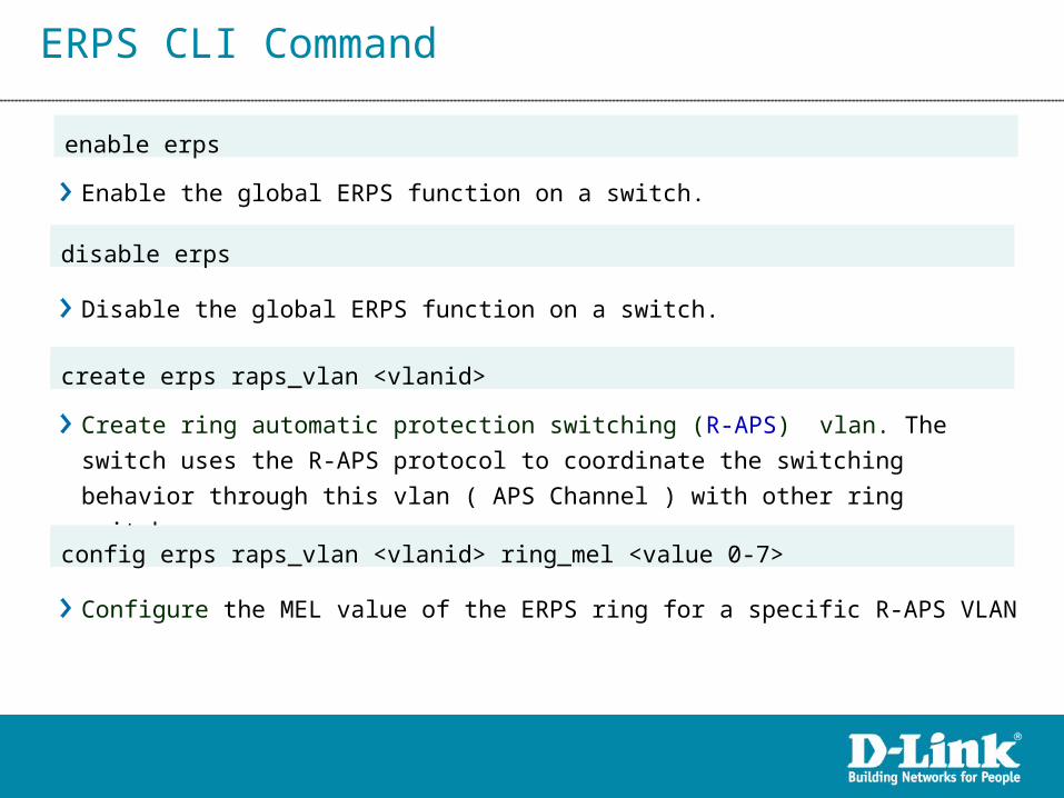
ERPS CLI Command
Enable the global ERPS function on a switch.
enable erps
disable erps
Disable the global ERPS function on a switch.
Create ring automatic protection switching (R-APS) vlan. The switch uses the
R-APS protocol to coordinate the switching behavior through this vlan ( APS
Channel ) with other ring switches.
create erps raps_vlan <vlanid>
config erps raps_vlan <vlanid> ring_mel <value 0-7>
Configure the MEL value of the ERPS ring for a specific R-APS VLAN

ERPS CLI Command
config erps raps_vlan <vlanid> ring_port [west <port> | east <port>]
Configure the ports connecting to the ERPS ring for a specific R-APS VLAN
There are “west” and “east” ring ports of the switch to the ring.
Configure the RPL port for a specific R-APS VLAN.
config erps raps_vlan <vlanid> rpl_port [west|east|none]
config erps raps_vlan <vlanid> rpl_owner [enable|disable]
Configure the RPL owner for a specific R-APS VLAN.
config erps raps_vlan <vlanid> protected_vlan [add|delete] vlanid <vidlist>
Configure the protected VLAN for a specific R-APS VLAN.
“protected_vlan” is used to configure the VLANs of the (service) traffic channel that
are protected by the ERPS function.

ERPS CLI Command
Configure the ERPS timers for a specific R-APS VLAN.
config erps raps_vlan <vlanid> timer { holdoff_time <value 0 - 10000> |
guard_time <value 10 - 2000 > | wtr_time <value 5 - 12>}]
Display ERPS configuration and operation information.
show erps {raps_vlan <vlanid> {sub_ring}}
config erps trap [enable | disable]
Configure the trap state of the ERPS.
config erps raps_vlan <vlanid> state [enable | disable]
Configure the state of the specified ring.

Agenda
What is ERPS ?
Drivers for ERPS
ERPS Technology
Benchmarking
ERPS CLI commands
Hands-on configuration
Application Examples

Internet
(A) DES 3052
(B) DES 3052P
1
2
Ring connection port 4(A) to port 3(B)
Ring connection port 3(A) to port 4(B)
DPH-125MS
DPH-125MS
UPLINK DVX-2000MS
Hands-on Configuration SampleTesting Scenario I Topology
RPL Owner
P3: West P4: East
P4: East P3: West

Testing Scenario I Topology
Set Switch A to be RPL Owner
config serial_port auto_logout never
create vlan vlanid 3
config vlan vlanid 3 add tagged 3-4
create erps raps_vlan 3
config erps raps_vlan 3 ring_port west 3
config erps raps_vlan 3 ring_port east 4
config erps raps_vlan 3 protected_vlan add vlanid 1
config erps raps_vlan 3 rpl_port west
config erps raps_vlan 3 rpl_owner enable
enable erps
Hands-on Configuration Sample
Set Switch B to be a regular switch
config serial_port auto_logout never
create vlan vlanid 3
config vlan vlanid 3 add tagged 3-4
create erps raps_vlan 3
config erps raps_vlan 3 ring_port west 3
config erps raps_vlan 3 ring_port east 4
config erps raps_vlan 3 protected_vlan add vlanid 1
config erps raps_vlan 3 rpl_port none
enable erps

Testing Scenario I Topology
Switch A
DES-3052:4#show erps
Command: show erps
ERPS Information
---------------------------
ERPS Status : Enabled
R-APS VLAN : 3
West Port : 3 (Signal Fail Blocked)
East Port : 4 (Forwarding)
RPL port : west port
RPL owner : Yes
Protection VLANs : 1
Ring MEL : 1
Holdoff time : 0 ms
Guard time : 500 ms
WTR time : 5 minutes
Log : Disabled
Current Ring State : Protection
Hands-on Configuration Sample
Switch B
DES-3052P:4#show erps
Command: show erps
ERPS Information
---------------------------
ERPS Status : Enabled
R-APS VLAN : 3
West Port : 3 (Forwarding)
East Port : 4 (Signal Fail)
RPL Port : None
Owner : Disabled
Protection VLANs : 1
Ring MEL : 1
Holdoff Time : 0 ms
Guard Time : 500 ms
WTR Time : 5 minutes
Log : Disabled
Current Ring State : Protection

Internet
DPH-125MS
DPH-125MS
DVX-2000MS
(A) DES 3052P
Ether Ring Connection
(D) DES 3052
(C) DES 3052P
(B) DES 3052
Testing Scenario II Topology
RPL Owner
P4: East
P4: East
P4: East
P4: East
P3: West
P3: West
P3: West
P3: West

Testing Scenario II Topology
Set Switch A to be RPL Owner create vlan vlanid 3
config vlan vlanid 3 add tagged 3-4
create erps raps_vlan 3
config erps raps_vlan 3 ring_port west 3
config erps raps_vlan 3 ring_port east 4
config erps raps_vlan 3 protected_vlan add vlanid 1
config erps raps_vlan 3 rpl_port west
config erps raps_vlan 3 rpl_owner enable
enable erps
Set Switch B to be a regular switch create vlan vlanid 3
config vlan vlanid 3 add tagged 3-4
create erps raps_vlan 3
config erps raps_vlan 3 ring_port west 3
config erps raps_vlan 3 ring_port east 4
config erps raps_vlan 3 protected_vlan add vlanid 1
config erps raps_vlan 3 rpl_port none
enable erps
Set Switch C to be a regular switch create vlan vlanid 3
config vlan vlanid 3 add tagged 3-4
create erps raps_vlan 3
config erps raps_vlan 3 ring_port west 3
config erps raps_vlan 3 ring_port east 4
config erps raps_vlan 3 protected_vlan add vlanid 1
config erps raps_vlan 3 rpl_port none
enable erps
Set Switch D to be a regular switch create vlan vlanid 3
config vlan vlanid 3 add tagged 3-4
create erps raps_vlan 3
config erps raps_vlan 3 ring_port west 3
config erps raps_vlan 3 ring_port east 4
config erps raps_vlan 3 protected_vlan add vlanid 1
config erps raps_vlan 3 rpl_port none
enable erps

Testing Scenario I Topology
Switch A
DES-3052P:4#show erps
Command: show erps
ERPS Information
---------------------------
ERPS Status : Enabled
R-APS VLAN : 3
West Port : 3 (Signal Fail Blocked)
East Port : 4 (Forwarding)
RPL port : west port
RPL owner : Yes
Protection VLANs : 1
Ring MEL : 1
Holdoff time : 0 ms
Guard time : 500 ms
WTR time : 5 minutes
Log : Disabled
Current Ring State : Protection
Hands-on Configuration Sample
Switch B
DES-3052:4#show erps
Command: show erps
ERPS Information
---------------------------
ERPS Status : Enabled
R-APS VLAN : 3
West Port : 3 (Forwarding)
East Port : 4 (Signal Fail)
RPL Port : None
Owner : Disabled
Protection VLANs : 1
Ring MEL : 1
Holdoff Time : 0 ms
Guard Time : 500 ms
WTR Time : 5 minutes
Log : Disabled
Current Ring State : Protection

Testing Scenario I Topology
Switch C
DES-3052P:4#show erps
Command: show erps
ERPS Information
---------------------------
ERPS Status : Enabled
R-APS VLAN : 3
West Port : 3 (Forwarding)
East Port : 4 (Forwarding)
RPL Port : None
Owner : Disabled
Protection VLANs : 1
Ring MEL : 1
Holdoff Time : 0 ms
Guard Time : 500 ms
WTR Time : 5 minutes
Log : Disabled
Current Ring State : Protection
Hands-on Configuration Sample
Switch D
DES-3052:4#show erps
Command: show erps
ERPS Information
---------------------------
ERPS Status : Enabled
R-APS VLAN : 3
West Port : 3 (Forwarding)
East Port : 4 (Forwarding)
RPL Port : None
Owner : Disabled
Protection VLANs : 1
Ring MEL : 1
Holdoff Time : 0 ms
Guard Time : 500 ms
WTR Time : 5 minutes
Log : Disabled
Current Ring State : Protection

Agenda
What is ERPS ?
Drivers for ERPS
ERPS Technology
Benchmarking
ERPS CLI commands
Hands-on configuration
Application Examples

Access
Aggregation
Core
DGS-3612/27G/50
IPTV Partner
VoIP Partner
Internet InternetDGS-8000
DGS-3700-12GNew!
DES-3526/50DES-3028/52
DES-3200-10/18/28
Coming Soon!
Core Level Ring Protection Aggregation Level Ring Protection Access Level Ring Protection
ETTx Solution
Future

Aggregation
Access
Core
DGS-3612/27G
DGS-8000/DGS-6600
DES-3528/52
DGS-3612/27G
Campus Core Ring Protection Aggregation devices connect to the nodes in core Ring (Optional) Access Ring Protection. Usually for long distance, sparse deployment
Campus Solution
Future

Appendix

Protection switching algorithm is based on priorities assigned to all triggers. When a ring node has multiple outstanding requests, it only responds to the one with highest priority.
Ring Protection Requests Priority
Request Type Priority
Local SF Local highest
Local Clear SF Local
R-APS (SF) Remote
WTR Expires Local
WTR Running Local
R-APS (NR, RB) Remote
R-APS (NR) Remote lowest
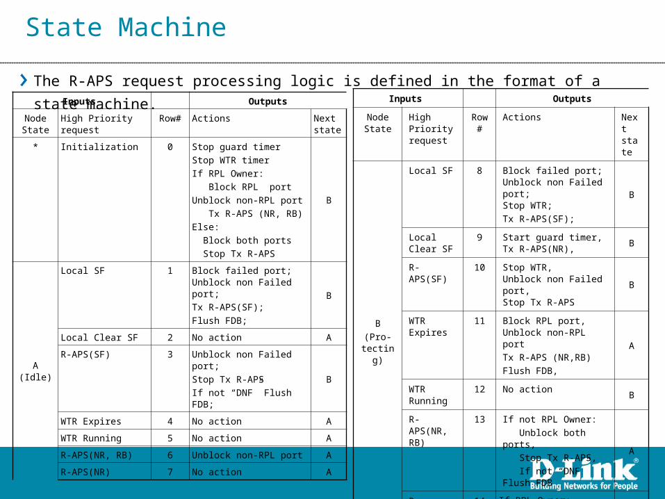
State Machine
Inputs Outputs
Node State
High Priority request
Row#
Actions Next state
B
(Pro-tecting)
Local SF 8 Block failed port;Unblock non Failed port;Stop WTR;
Tx R-APS(SF);
B
Local Clear SF
9 Start guard timer,Tx R-APS(NR),
B
R-APS(SF) 10 Stop WTR,Unblock non Failed port,Stop Tx R-APS
B
WTR Expires
11 Block RPL port,Unblock non-RPL port
Tx R-APS (NR,RB)
Flush FDB,
A
WTR Running
12 No action B
R-APS(NR, RB)
13 If not RPL Owner:
Unblock both ports,
Stop Tx R-APS,
If not “DNF” Flush FDB
A
R-APS(NR) 14 If RPL Owner:
Start WTRB
Inputs Outputs
Node State
High Priority request Row# Actions Next state
* Initialization 0 Stop guard timer
Stop WTR timer
If RPL Owner:
Block RPL port
Unblock non-RPL port
Tx R-APS (NR, RB)
Else:
Block both ports
Stop Tx R-APS
B
A (Idle)
Local SF 1 Block failed port;Unblock non Failed port;
Tx R-APS(SF);
Flush FDB;
B
Local Clear SF 2 No action A
R-APS(SF) 3 Unblock non Failed port;
Stop Tx R-APS
If not “DNF” Flush FDB;
B
WTR Expires 4 No action A
WTR Running 5 No action A
R-APS(NR, RB) 6 Unblock non-RPL port A
R-APS(NR) 7 No action A
The R-APS request processing logic is defined in the format of a state machine.
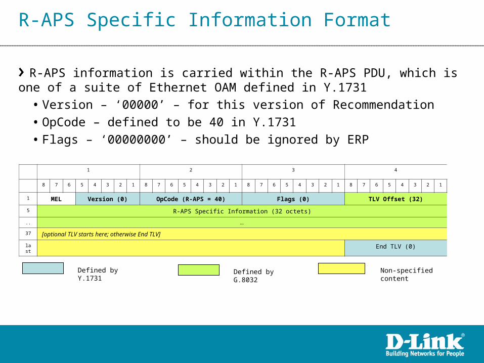
R-APS Specific Information Format
R-APS information is carried within the R-APS PDU, which is one of a suite of Ethernet OAM defined in Y.1731
• Version – ‘00000’ – for this version of Recommendation
• OpCode – defined to be 40 in Y.1731
• Flags – ‘00000000’ – should be ignored by ERP
1 2 3 4
8 7 6 5 4 3 2 1 8 7 6 5 4 3 2 1 8 7 6 5 4 3 2 1 8 7 6 5 4 3 2 1
1 MEL Version (0) OpCode (R-APS = 40) Flags (0) TLV Offset (32)
5 R-APS Specific Information (32 octets)
.. …
37 [optional TLV starts here; otherwise End TLV]
last End TLV (0)
Defined by Y.1731 Defined by G.8032 Non-specified content

R-APS Specific Information Format
Specific information (32octets) defined by G.8032
• Request/State(4bits) – ‘1011’ = SF | ’0000’ = NR | Other = Future
• Status – RB (1bit) – Set when RPL is blocked (used by RPL Owner in NR)
• Status – DNF (1bit) – Set when FDB Flush is not necessary (Future)
• NodeID (6octets) – MAC address of message source node (Informational)
• Reserved1(4bits), Status Reserved(6bits), Reserved2(24octets) - Future development
1 2 3 4
8 7 6 5 4 3 2 1 8 7 6 5 4 3 2 1 8 7 6 5 4 3 2 1 8 7 6 5 4 3 2 1
Request /State Reserved 1 Status Node ID (6 octets)
RB
DNF
Status Reserved
(Node ID)
Reserved 2 (24 octets)

Link Failure (Normal to Protection)
2 3 4 5 61
SF
Normal
Protectionstate
failure
R-APS channel block
Client channel block
SF
A
RPL Owner
B
Message source
SFSF
CD
E
SFSFSF SFF
50 m
s
G
RPL
Flush Flush
FlushFlushFlushFlush
SFSF

SF
Failure Recovery
2 4 5 6
RPL
1
Normal
Protectionstate
recovery
failure
RPL Owner
B
SF SFSF
SF SF
F
A
E
NRNR
NRNR
NR, RPL Blocked
NR, RPL Blocked
NR, RPL Blocked
G
NRNR, RPL Blocked
NR, RPL Blocked
NR, RPL Blocked
D
Flush
FlushFlush
FlushFlush
50 m
sC
on
firm
atio
n
time
H
3
NR NR
C
R-APS channel block
Client channel blockMessage source
Flush

Reference
Ethernet Ring Protection Switching by the ITU
Telecommunication Standardization Sector (ITU-T) ITU-T Rec.
G.8032, 2008.
Ethernet Ring Protection for Carrier Ethernet Networks
by JEONG-DONG RYOO in Electronics and Telecommunications
Research Institute (ETRI), South Korea