technology development in welding - orbital weldingpaper the working of the orbital welding machine,...
TRANSCRIPT

© IJEDR 2019 | Volume 7, Issue 1 | ISSN: 2321-9939
IJEDR1901057 International Journal of Engineering Development and Research (www.ijedr.org) 314
Technology Development In Welding - Orbital Welding
Doddi Abhinay Kumar, Boddu Varshini, Rao Harshita Research scholar,
Department of Power Engineering, GMR Institute of Technology, Andhra Pradesh, India _____________________________________________________________________________________________________ Abstract - Orbital welding machine is a tool used to weld rods or pipes circumferentially. Circumferential welding is always a difficult task to take on. Even the finest of the highly skilful workers also may end up with few welding defects often. Also it is difficult to weld rods of bigger dimensions. To overcome all these problems the best solution available is Orbital Welding Machine. In this welding a tungsten inert gas (TIG) electrode is rotated around the work pieces, which are held firmly. The electrode is rotated for 1800 or 3600 depending on the type of orbital welding equipment used. Though the Orbital Welding Machines are tailor made but still they offer a wide range of operation, i.e. for different diameters of the pipes and also for a wide ran ge of materials. This flexibility will buy them a place in the industry in the view of mass production. Apart from this the other big reason for anyone to prefer Orbital Welding is its accuracy. The parameters which affect the welding like arc length, welding speed, etc. can be adjusted priorly with the help of the software. The motion of the electrode is guided by a predetermined programme. In this paper the working of the Orbital Welding Machine, its parts, advantages and disadvantages will be discussed. Index Terms - Orbital welding , Pipe welding. _____________________________________________________________________________________________________
I. INTRODUCTION
Orbital welding is the technology to weld the pipes or tubes. In case of pipelines this technology is used at a large scale as the pipeline having number of pipes joined together. These pipelines may have chances of leakages at their joints. These leakages may be harmful if the pipelines are used for gas supply or any harmful liquid supply like acid etc. through it. Also the leakage may cause loss in the productivity. To overcome these problems the welding technology is required to improve. As the use of pipeline is increasing day by day hence the requirement of orbital welding is also increasing.Like the pipe welding the tube welding is also become primary requirement of the industries now days. In some industries there is mass production of these tubes or pipes hence the increase productivity is need of the industries. For that the improvement in the orbital welding is required now.
II. HISTORY OF ORBITAL WELDING
Orbital welding first found use in the 1960’s when the aerospace industry recognized the need for a superior joining technique for aircraft hydraulic lines. The solution: a mechanism to rotate a welding arc from a tungsten electrode around a tube-weld joint. Regulating weld current with a control system automated the entire process. The result was a more precise, reliable method than manual welding. Orbital welding became practical for many industries in the early 1980’s with the development of portable combination power supply/control systems that operated from 110-V AC. Currently, typical industries using orbital welding include aerospace; food, dairy, and beverage; nuclear; offshore; pharmaceutical; and semiconductor. Other applications include boiler tubing and tube and pipe fittings, valves, and regulators. Modern orbital welding systems offer computer controls that store welding schedules in memory. The skills of a certified welder are thus built into the system, enabling the production of enormous numbers of identical welds and leaving little room for error or defects
III. ORBITAL WELDING PROCESS
Welding means to joint the two metals or two joint each other with the help of heat in the welding process recent technology is orbital welding. The orbital welding was initially used to done by manually. In manual welding welder either used to weld the tube or pipe by rotating weld head or by rotating tube and keeping weld head as it is. In this process the time required to weld was more and also that weld was not continuous. This process was the process at the start but then the orbital welding techniques where introduced.For the orbital welding the process was introduced where the weld head was steady and the pipes where rotating. The positioners were made which were used to hold the tubes together and to weld them. In this technique the positione0r hold the job and rotate in 360P rotation with the speed controlled by feed control unit.These positioners were semi-automatic positioners.

© IJEDR 2019 | Volume 7, Issue 1 | ISSN: 2321-9939
IJEDR1901057 International Journal of Engineering Development and Research (www.ijedr.org) 315
Fig.3.1 Positioner for orbital welding
In modern techniques the computers were used for orbital welding. In the orbital welding process the tubes or pipes are clamped in place and an orbital weld heads rotates an electrode and electric arc around the weld joint to make the required weld. An orbital welding system consists of a power supply and an orbital weld head.The power supply/control system supplies and controls the welding parameters according to the specific weld program created or recalled from memory. This supply provides the control parameters, the arc welding current, the power to drive the motor in the weld head, and switches the shield gas on/off as necessary. Orbital weld heads are normally of the enclosed type, and provide an inert atmosphere chamber that surrounds the weld joint. Standard enclosed orbital weld heads are practical I welding tube sizes from 1/16inch to 6 inches with wall thicknesses of up to154 inches. Larger diameters and wall thicknesses can be accommodated with open style weld heads.
Fig.3.2 Modern Orbital Welding
IV. TYPES OF ORBITAL WELDING
There are two types of orbital welding. a. Open head mechanism b. Closed head mechanism
Fig 4.1 types of orbital welding
CLOSED HEAD ORBITAL WELDING Closed head mechanism for small diameters. For welds critical thin-wall tubing and pipes with small and medium- sized, fabricators select a closed head device. Standard closed orbital weld heads can be used for tube sizes from 1.6 to 162 mm (this number can be varies e.g. up to 200 mm or 6.3 to 203 mm ) with wall thicknesses of up to 3.9 mm (0.4 to 12.7 mm . The head housing in close head systems can be fixed or adapter types with limited range of accommodation.
© IJEDR 2019 | Volume 7, Issue 1 | ISSN: 2321-9939
IJEDR1901057 International Journal of Engineering Development and Research (www.ijedr.org) 316
Fig.4.2 Closed head orbital welding
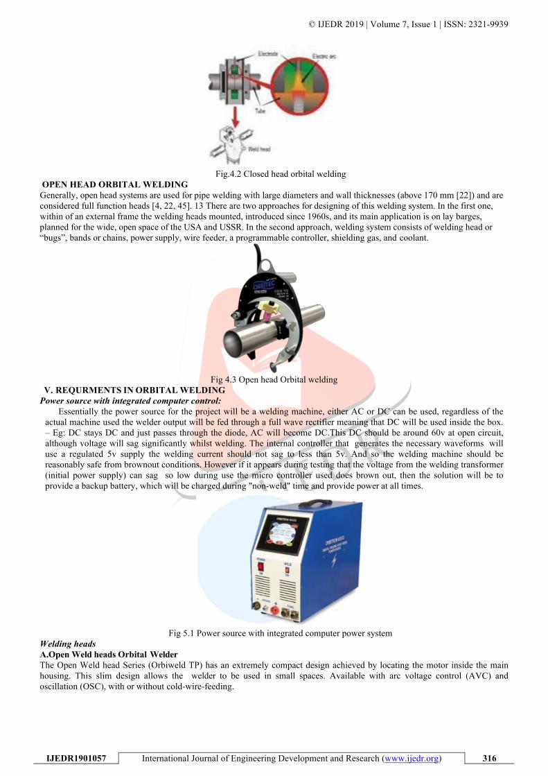
OPEN HEAD ORBITAL WELDING Generally, open head systems are used for pipe welding with large diameters and wall thicknesses (above 170 mm [22]) and are considered full function heads [4, 22, 45]. 13 There are two approaches for designing of this welding system. In the first one, within of an external frame the welding heads mounted, introduced since 1960s, and its main application is on lay barges, planned for the wide, open space of the USA and USSR. In the second approach, welding system consists of welding head or “bugs”, bands or chains, power supply, wire feeder, a programmable controller, shielding gas, and coolant.
Fig 4.3 Open head Orbital welding
V. REQURMENTS IN ORBITAL WELDING Power source with integrated computer control:
Essentially the power source for the project will be a welding machine, either AC or DC can be used, regardless of the actual machine used the welder output will be fed through a full wave rectifier meaning that DC will be used inside the box. – Eg: DC stays DC and just passes through the diode, AC will become DC.This DC should be around 60v at open circuit, although voltage will sag significantly whilst welding. The internal controller that generates the necessary waveforms will use a regulated 5v supply the welding current should not sag to less than 5v. And so the welding machine should be reasonably safe from brownout conditions. However if it appears during testing that the voltage from the welding transformer (initial power supply) can sag so low during use the micro controller used does brown out, then the solution will be to provide a backup battery, which will be charged during "non-weld" time and provide power at all times.
Fig 5.1 Power source with integrated computer power system
Welding heads A.Open Weld heads Orbital Welder The Open Weld head Series (Orbiweld TP) has an extremely compact design achieved by locating the motor inside the main housing. This slim design allows the welder to be used in small spaces. Available with arc voltage control (AVC) and oscillation (OSC), with or without cold-wire-feeding.
© IJEDR 2019 | Volume 7, Issue 1 | ISSN: 2321-9939
IJEDR1901057 International Journal of Engineering Development and Research (www.ijedr.org) 317
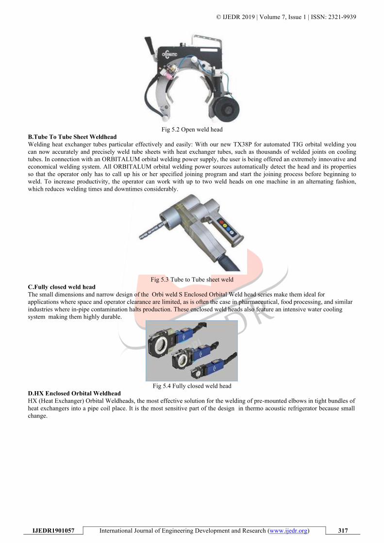
Fig 5.2 Open weld head
B.Tube To Tube Sheet Weldhead Welding heat exchanger tubes particular effectively and easily: With our new TX38P for automated TIG orbital welding you can now accurately and precisely weld tube sheets with heat exchanger tubes, such as thousands of welded joints on cooling tubes. In connection with an ORBITALUM orbital welding power supply, the user is being offered an extremely innovative and economical welding system. All ORBITALUM orbital welding power sources automatically detect the head and its properties so that the operator only has to call up his or her specified joining program and start the joining process before beginning to weld. To increase productivity, the operator can work with up to two weld heads on one machine in an alternating fashion, which reduces welding times and downtimes considerably.
Fig 5.3 Tube to Tube sheet weld
C.Fully closed weld head The small dimensions and narrow design of the Orbi weld S Enclosed Orbital Weld head series make them ideal for applications where space and operator clearance are limited, as is often the case in pharmaceutical, food processing, and similar industries where in-pipe contamination halts production. These enclosed weld heads also feature an intensive water cooling system making them highly durable.
Fig 5.4 Fully closed weld head
D.HX Enclosed Orbital Weldhead HX (Heat Exchanger) Orbital Weldheads, the most effective solution for the welding of pre-mounted elbows in tight bundles of heat exchangers into a pipe coil place. It is the most sensitive part of the design in thermo acoustic refrigerator because small change.

© IJEDR 2019 | Volume 7, Issue 1 | ISSN: 2321-9939
IJEDR1901057 International Journal of Engineering Development and Research (www.ijedr.org) 318
Fig 5.5 HX Enclosed orbital weld head
E.Weld Joint Fit up Weld joint fit-up depends on the weld specification requirements for tube straightness, weld concavity, reinforcement, and
drop-through. If no specification exists, the molten material must flow and compensate for tube mismatch and any gap in the weld joint
. F.SHIELD GASES: An inert gas is required on the tube OD and ID during welding to prevent the molten material from combining with the oxygen in the ambient atmosphere. The objective of the welder should be to create a weld that has zero heat tint at the weld zone. G.Tungsten electrodes: The tungsten welding electrode the source of the welding arc is one of the most important elements of the welding system that is commonly ignored by welding system users. While no one would refute the importance of the ignition device on an automobile air bag, the rip cord for a parachute, or quality tires for automobiles, the importance of tungsten electrodes for quality welding is often overlooked. VI. ADVANTAGES
The very much importance of orbital welding technology in the welding field. There are many reasons for using orbital welding equipment. The ability to make high quality, consistent welds repeatedly, at a speed close to the maximum weld speed, offer many benefits to the user.
HIGH WELD ABILITY: Obtain a much better quality by automated TIG welding compared to manual welding. Welds produced manually are not always of a poor quality, but the number of discarded tubes / defects is higher compared to TIG welding TRAINING AND COMPETENCES: Using an orbital welding equipment is possible without a long and tedious training. You do not need to bean accomplished welderto proceed to orbital welding. Training sessions are typically much shorter and easier compared to those of a specialized welder.This means a gain in terms of labour costs and in deploying the welding teams
HIGH PRODUCTIVITY: Automated orbital TIG welding provides you with a better productivity compared to manual welding. The welding tasks can be registered and repeated any time it will be necessary. When you make a weld manually, a variety of factors have a direct influence over it, whereas with automated TIG welding, the welds can be repeated by the equipment as often as required in the future.
A WELDING TECHNOLOGY SUITING CONFINED SPACE ENVIRONMENTS: Orbital welding equipment allows welding in all situations: confined spaces, lack of visibility, high-risk environments. Welding can be performed from a remote location and a special welding camera can be added to the equipment, reducing any risk for the operators.
ORBITAL TIG WELDING ENSURES BETTER MONITORING AND TRACEABILITY Orbital welding equipment allows great recording of each weld. Every welding parameter is registered, the welds can be repeated any time by means of the data acquisition of each weld.
VII. APPLICATIONS Orbital welding is having number of applications in different fields. Their applications are increases day by day now. Some of their applications are listed below.

© IJEDR 2019 | Volume 7, Issue 1 | ISSN: 2321-9939
IJEDR1901057 International Journal of Engineering Development and Research (www.ijedr.org) 319
AERO SPACE The aerospace industry was the first to recognize the advantages of automated orbital welding. The high pressure systems of a single aircraft can contain more than 1,500 welded joints, all automatically created with orbital equipment. BOILER TUBE Boiler-tube installation and repair offer perfect applications for orbital welding. Compact orbital weld heads can be clamped in place between rows of heat- exchanger tubing. FOOD, DIARY & BEVERAGE INDUSTRIES These industries require consistent full penetration welds on all weld joints. For maximum piping-system efficiency, the tubing and tube welds must be as smooth as possible. Any pit, crevice, crack, or incomplete weld joint can trap the fluid flowing inside the tubing, becoming a harbor for bacteria. NUCLEAR PIPING: The nuclear industry, with its severe operating environment and associated specifications for high quality welds, has long been an advocate of orbital welding. PHARMACEUTICAL Pharmaceutical process lines and piping systems deliver high-quality water to their processes. This requires high quality welds to ensure a source of water from the tubes uncontaminated by bacteria, rust, or other contaminant. Orbital welding ensures full-penetration welds with no overheating that could undermine the corrosion resistance of the final weld zone. SEMICONDUCTOR INDUSTRY The semiconductor industry requires piping systems with extremely smooth internal surface finish to prevent contaminant buildup on the tubing wall or weld joints. Once large enough, a build-up of particulate, moisture, or contaminant could release and ruin the batch process.
VIII. CONCLUSION: Orbital welding technology is being improved day by day and it has gained a huge attention every industry for its accurate, reliable, efficient, results. Reduction in processing time and cost has made the orbital welding unique and significant. Manual welding always have inconsistency and defects over welds and with this advanced and high qualified technology like orbital welding tube to tube, pipe to pipe welding and tube to tube shoot has become very easy without any much effort.
REFERENCES
[1] Omkar JoshiP, Dr. ArunkumarP “Overview of Orbital Welding Technology” International Journal of Innovative Science, engineering and technology, 2015. [2] Bernard Mannion, Jack Heinzman “Understanding the basic principles behind orbital tube welding” article published in issue of Flow Control, DecemberV1999. [3] Hamidreza Latifi, “Advanced orbital pipe welding”, Lappeenranta university of technology, 2012. [4] J. Doherty., G. R. Salter, "Development in procedure selection techniques, "Welding Institute Research Bulletin, vol. 18, no. 6, 1977. [5] https://www.sfiorbimax.com.au/collections/orbital- welding. [6] https://www.liburdi.com/welding-systems-dimetrics. [7] B. Mannion., J. Heinzman, "Setting up and determining parameters for orbital tube welding," The Fabricator, vol.29, pp 26-30, 1999.