technology development of hts twisted stacked-tape cable
TRANSCRIPT
January 27, 2013
Plasma Science and Fusion Center Massachusetts Institute of Technology
Cambridge, MA 02139
This work was supported by the U. S. Department of Energy, Office of Fusion Energy Science under Grants: DE-FC02-93ER54186, and partially DE-SC0004062 and Supercon DOE STTR Phase II DE-SC0004269. A portion of this work was performed at the National High Magnetic Field Laboratory, which is supported by NSF, the State of Florida and the DOE. Reproduction, translation, publication, use and disposal, in whole or in part, by or for the United States government is permitted.
PSFC/JA-‐13-‐9
Technology Development of HTS Twisted Stacked-Tape Cable: Part 1
M. Takayasu, L. Chiesa*, J.V. Minervini, W. Nachtrab**, M.K.
Rudziak**, and T. Wong**
*Tufts University, Mechanical Engineering, Medford, MA 02155 USA **Supercon, Inc., Shrewsbury, MA 01545, USA

2
ABSTRACT
A new magnet winding technique, Stacked-Tape Twist-Wind (STTW) of YBCO tapes using the Twisted Stacked-Tape Cabling (TSTC) concept has been developed. A pentagonal shape coil sample made of a 2.3 m long, 50-tape YBCO conductor was fabricated by this method, and the cable was soldered. The critical current of the pentagonal sample was 4.0 kA at 100 µV/m at 19.7 T in liquid helium. The test results revealed that the soldered YBCO cable started degrading for an electromagnetic Lorentz force of 50 kN/m. A curved saddle coil winding using a STTW technique was demonstrated. Stability analysis was performed for various TSTC conductors. Two industrial scalable approaches: (1) Expendable mandrel technique and (2) Filled billet technique were developed by Supercon, Inc. TSTC conductors fabricated by the methods were tested, and the test results were presented.
KEYWORDS: HTS cable, twisted stacked tape cable, stacked-‐tape twist-‐wind, critical current, high temperature superconductor, saddle coil, and accelerator magnet.

3
TABLE OF CONTENTS
I. INTRODUCTION .................................................................................................................................................. 4
II. STACKED-‐TAPE TWIST-‐WIND METHOD ................................................................................................. 4 2.1 COIL WINDING METHOD ................................................................................................................................... 4 2.2 PENTAGON COIL FABRICATION AND TEST ..................................................................................................... 5 2.3 CURVED SADDLE COIL WINDING DEMONSTRATION .................................................................................... 7 2.4 SUMMARY ............................................................................................................................................................. 8
III. INVESTIGATION OF CRYOGENIC STABILITY OF TSTC ...................................................................... 8
IV. TEST RESULTS OF CABLES FABRICATED AT SUPERCON ............................................................. 12
V. SUMMARY ........................................................................................................................................................... 18
VI. REFERENCES ..................................................................................................................................................... 18

4
I. INTRODUCTION We have been developing a HTS tape cabling technique called Twisted Stacked-Tape
Cabling (TSTC) method [1]-[3]. To complement the cabling method, we have developed a new magnet winding method called the Stacked-Tape Twist-Wind (STTW) technique, suitable for the fabrication of the complicated 3D windings needed for various high-energy accelerator magnets. The STTW method will allow the fabrication of high-current, high-current-density magnets, such as the dipole and quadrupole magnets used in High Energy Physics magnets, as well as various industrial electric machines, using 2G HTS flat tapes. In this report, test results of a 2.3 m, 50-tape YBCO tape coil fabricated with the STTW method are presented. Cable performance analysis of various TSTC conductors composed of different amounts of copper and various solders are discussed. Supercon has been developing industrially feasible methods to fabricate a long TSTC. Those fabrication methods and test results of fabricated sample are also presented.
II. STACKED-TAPE TWIST-WIND METHOD 2.1 Coil Winding Method
A new method for winding a magnet coil with the stacked-tape cables has been developed based on the concept of the Twisted Stacked-Tape Cable (TSTC) [4]. A twisted stacked-tape cable is easily bendable in the direction where the local bending radius is perpendicular to the tapes in the stack, but not in other directions. Fig. 2.1 (a) shows a section of a TSTC conductor and the locations where it can be easily bent are indicated in the figure (drawing plane). The locations where the bending is difficult are also indicated. Taking this in consideration, it is possible to control the winding process and wind various shape coils by twisting and bending following the easy bend direction during winding, so that sharp local bending can be obtained by adjusting the twist pitch. The twist pitch can be locally adjusted based on the coil shape and diameter. A sharp bending of about 25 mm diameter and the minimum twist-pitch of about 200 mm would be possible for a 50-tape YBCO cable. As examples, Figs. 2.1 (b) and (c) show cable windings on pentagonal and hexagonal cylinders, respectively. On these cylinder surfaces a stacked-tape cable can be wound easily by sharply bending the stack of tapes at the corners of a polygon and then twisting along the straight sides of the polygon. In other words, the stack-tape cable is twisted while being wound, instead of being twisted in a straight configuration before winding. The straight length should be half of the cable twist-pitch or a multiple of it. We will call the cable winding method “Stacked-Tape Twist-Wind” (STTW). The STTW will allow fabricating a complicated shaped magnet of 2G tapes, such as racetrack and saddle coils.

5
Fig. 2.1 (a) Twisted stacked-tape cable showing the locations of easy and difficult bendings along the cable. (b) and (c) Cable windings of the stacked-tape twist-wind (STTW) method on pentagonal and hexagonal cylinders, respectively.
2.2 Pentagon Coil Fabrication and Test A pentagon winding cable (Fig. 2.1 (b)) was fabricated by a STTW method and tested at
the NHMFL, Florida State University. A winding sample holder was made out of an aluminum disk of 165 mm diameter and 76 mm length. A winding groove (a half round groove 8.2 mm in diameter) was machined in a pentagonal shape on the circular cylinder. The pentagon shape winding former was roughly 3-turn in length, with the sides 96.5 mm long and about 25 mm round corner radius. The entire surface of the aluminum sample holder was treated with a hard anodizing process to provide electric insulation.
(a) (b)
Fig. 2.2 (a) 50 tape, 2.5-turn superconductor coil composed of 0.1 mm thick, 4 mm wide YBCO tapes wound on a 165 mm diameter pentagon cylinder. (b) Enlarged view of a 3D sharp bending section.

6
A stacked-tape cable was wound in the groove and twisted as it was laid in the channel
allowing for sharp bending, as shown in Fig. 2.2 (a). The cable was composed of 50 SuperPower YBCO tapes. The tapes were stacked between two 0.51 mm thick copper strips. The stacked-tape cable was loosely wrapped with a fine stainless steel wire 0.23 mm in diameter (with a helical pitch of about 20 mm), so that the tapes could smoothly slip during twist-winding. Each tape thickness and width were 0.1 mm and 4 mm, respectively.
The stacked tape cable was bent at each corner as seen in Fig. 2.2 (a) and twisted a half twist length along the 96.5 mm straight section by hand. A 3D sharp bending section (about 25 mm radius) is shown in Fig. 2.2 (b). A total of 2.5 turns were wound on the pentagonal shape cylinder. The total cable length was 2.32 m of which 1.35 m was on the aluminum sample holder. Fig. 2.3 (a) shows the pentagonal sample on a probe.
After winding, the cable was soldered with 60%Sn-40%Pb. The solder was between YBCO tapes and the cable surface, and there was no solder filler outside the cable in the winding groove.
The terminations of the YBCO cables were fabricated using our standard joint method using BSCCO tapes. The terminations are shown at the left top corner in Fig. 2.3 (a). The distance between the terminations and the aluminum sample holder was 0.48 m. An enlarged view of the terminations is shown in Fig. 2.3 (b). The YBCO and BSCCO overlapped joint section (about 50 mm) is clamped with G10 plates and ten 4-40 screws. Each screw was tightened with a torque of 0.64 N-m.
The pentagonal YBCO coil sample was tested in a liquid helium cryostat using the 20 T,
195 mm warm bore Bitter magnet at NHMFL, Florida State University. Sample current was provided using a 20 kA, 10 MW Bitter magnet DC power supply through a 4.7 m-Ohm stainless-steel tube resistor connected in series with the test sample.
Fig. 2.4 shows the test result of an I-V curve of 1 m voltage tap at the background field of 19.7 T at 4.2 K. The critical current at 100 µV/m was 4.0 kA with a low n-value of 12. The cable quenched at 4.7 kA. The sample was apparently degraded as the expected critical current was more than 5 kA. It is believed that this degradation was caused by the Lorentz force. As it can be seen in Fig. 2.4, the voltage started increasing at around 2.5 kA where the electromagnetic Lorentz force is 50 kN/m (2.5 kA x 20 T). The tapes of the cable were soldered, however the twisted square cross-section cable was sitting in a round groove. Consequently, it was not well supported against the large Lorentz load. We will develop a better method to support a TSTC conductor.

7
(a)
(b)
Fig. 2.3 (a). The pentagon sample (2.5 turn 50 YBCO tapes) fabricated using a stacked-tape twist-wind method on a probe. (b) Terminations of the 50 tape YBCO cable using YBCO-BSCCO-copper terminators.
Fig. 2.4 I-V curve of the 50-tape YBCO cable composed of 4 mm wide SuperPower YBCO tapes, measured at 19.7 T and 4.2 K.
2.3 Curved Saddle Coil Winding Demonstration In various magnet applications such as accelerator magnets for High Energy Physics
research and electric power machines of motors and generators, the typical dipole and quadrupole winding configurations are “racetrack” or “saddle” [5]. Fig. 2.5 shows a winding demonstration, using the winding technique described above, of a curved saddle winding on a 50 mm diameter tube, which shows a U-turn portion of one turn of a saddle coil. The cable is a 50-tape stacked YBCO cable.
A curved saddle coil requires complicated 3D curved windings in a circumferential direction on a circular tube. An advantage of the Stacked-Tape Twist-Winding method for YBCO tapes is that it allows very sharp bending of about 25 mm diameter 3D-bending curves

8
by adjusting the twist pitch and direction. The twisting direction should be selected properly to obtain the desired windings. In saddle coil as the one shown in Fig. 2.5, the twisting direction of a half of the U-turn section (or every quarter turn) can be selected to fabricate a symmetrical winding for a saddle coil.
Fig. 2.5 A U-turn portion of one turn of a saddle coil demonstrating a curved saddle winding on a 50 mm diameter tube. The cable is composed of 50 YBCO tapes.
2.4 Summary A new coil winding technique, the Stacked-Tape Twist-Wind (STTW) method, using the
Twisted Stacked-Tape cabling concept has been developed, which makes possible manufacturing complicated magnet coil windings using a HTS tape conductor. The STTW method will allow the fabrication of high-current, high-field magnets using 2G HTS flat tapes, such as the dipole and quadrupole magnets used in High Energy Physics magnets, as well as various industrial electric machines.
A pentagonal sample composed of 50 YBCO tapes was fabricated using the new STTW technique, and the critical current of the sample was tested to be 4.0 kA at 100 µV/m at 19.7 T in liquid helium. These results are encouraging and demonstrate that the TSTC method for YBCO tapes could be used in various applications. However, it was observed that the cable degraded at Lorentz load higher than 50 kN/m. Cable supporting method must be improved to reduce degradation.
III. INVESTIGATION OF CRYOGENIC STABILITY OF TSTC Stability analyses have been performed for various TSTC conductors of different
configurations of copper stabilizers and solder fillings. Cryogenic stability of a conductor is evaluated by Stekly limiting current equation
(3.1)
where p is the cooled perimeter of the conductor

9
h is the heat transfer coefficient ρ is the resistivity of the copper or solder Acu is the copper cross-section Tc is the critical temperature Tb is the bath temperature
The limiting currents were evaluated for the following three different types of 32-tape YBCO TSTC conductors (SuperPower YBCO tapes of 4 mm width, 0.1 mm thickness) by Eq. (3.1) with h = 1000 W/m2 K, Tc = 88 K and Tb = 77 K:
1. 32 tapes in a 7.9 mm dia. 0.81 mm wall copper tube with 60Sn-40Pb solder. 2. 32 tapes stacked between two 4.8 mm width, 0.81 mm thickness copper strips without
solder. 3. 32 tapes stacked between two 4.8 mm width, 0.81 mm thickness copper strips soldered
with 60Sn-40Pb. The pictures of the conductors and calculated results of the limiting currents are given in
Table 3.1. Copper and 60Sn-40Pb solder resistivities were assumed to be 2x10⁻⁹ Ω-m and 3x10⁻⁹ Ω-m, respectively.
Table 3.1 Stekly Limiting Currents of three different 32-tape YBCO TSTC conductors.
Test results of the 32 tape YBCO TSTC conductors were reported [2]. The critical current of a 32 tape conductor at 77 K was about 1.5 kA at self-field. Therefore one can say that the 32 TSTC conductor in a 7.9 mm diameter copper tube with 60Sn-40Pb can be cryostable in liquid nitrogen, however the conductors of the stacked tapes and even soldered conductors without a solder filled copper tube are not cryostable. It is noted that the Stekly limiting current criterion is a simple analysis giving an overestimation of the effects of copper stabilizer.
We have evaluated the limiting current for the operation temperature Tb and the magnetic field up to 15 T by extending the Stekly limiting current equation. The limiting current I*
lim is given for cryo-stabilization up to a given temperature T* by Eq. (3.2).

10
(3.2)
where
Ic is the critical current at Tc*,
IstLim is the Stekly limiting current given from Eq. (3.1) as follows,
(3.3)
The limiting currents were assumed to be cryogenically stable under the operation at the given critical current Ic at a given temperature T*.
The limiting currents for 40-tape YBCO TSTC conductors at an operation at 4.2 K and to be in cryostability up to 20 K were analyzed using the following parameters: h = 1000 W/m2 K, Tc
* = 20 K, Tb = 4.2 K, ρ = (2*10-8)/RRR+ 0.48*10-10 B Ω-m for the copper the resistivity, here RRR=100 and B is the magnetic field. The resistivities of indium, 60Sn-40Pb and 95Sn-5Ag were obtained from Tom Painter [6], [7]. The data measured at 4.2 K were plotted as a function of the magnetic field in Fig. 3.1 [7]. The results of the limiting current as a function of the magnetic field are shown in Figs. 3.2 and 3.3.
Fig. 3.1 Resistivity of various solders as a function of the magnetic field at 4.2 K [7] (courtesy of T. Painter, NHMFL).
Fig. 3.2 shows the limiting currents for 40 Tape YBCO TSTC conductors in a 7.9 mm (5/16”) diameter, 0.81 mm wall copper tube filled with three different solders 60Sn-40Pb, 95Sn-5Ag and indium for Tb=4.2 K. In the figure a calculated result for the case filled with copper instead of a solder is also plotted. Effects of filler materials are seen in the figure. Indium has very good electric conductivity at even high magnetic fields. The limiting current of the indium filled conductor provides as high as the calculated critical current of the 40-tape YBCO conductor (plotted with X marks) at the field higher than 8 T.
I lim* =
Ic + Ic2 + 4IstLim2
IstLim =phACu (T
* −Tb )ρ

11
Fig. 3.2 Calculated limiting currents at 4.2 K for copper sheathed TSTC conductors filled with various solders. The insert shows an enlarged plots between 10 T and 15 T. By using Eq. (3.2), the limiting currents of the following four different types of 40 tape YBCO TSTC conductors were also analyzed, and the results are shown in Fig. 3.3.
1. Stacked tapes between two 4.8 mm width, 0.81 mm thickness copper strips without solder.
2. Stacked tapes between two 4.8 mm width, 0.81 mm thickness copper strips solder-filled with 60Sn-40Pb solder.
3. Tape conductor in a 7.9 mm (5/16”) diameter, 0.81 mm thickness wall copper tube filled with 60Sn-40Pb solder.
4. Tapes in three slots of 4.1 mm width x 1.4 mm deep in a copper rod of 9.5 mm (3/8”) diameter.

12
Fig. 3.3 Calculated limiting currents at 4.2 K for various TSTC conductors as a function of the magnetic field.
In Fig. 3.3 the limiting current of the 9.5 mm copper rod conductor is seen to be getting close to the critical current of a 40 tape YBCO cable, and it shows much better performance than others.
In order to evaluate stability of a YBCO TSTC conductor, various type of conductors have been compared based on the Stekly limiting current equation. As mentioned earlier, it is known that the Stekly limiting current criterion gives an overestimation of the copper stabilizer. A more precise dynamic stability analysis taking into account a transient stability under anticipating disturbances during operation is required.
IV. TEST RESULTS OF CABLES FABRICATED AT SUPERCON Supercon has been developing industrially feasible methods to fabricate a long TSTC.
Critical current tests of various TSTC samples made by Supercon were examined. Those samples were made by two industrial approaches: (1) Expendable mandrel technique and (2) Filled billet technique. The fabrication steps of these methods are described below:
1. Expendable Mandrel Technique
1. Copper tube partially swaged down and then drawn over square steel mandrel to produce round tube (7.92 mm OD) with square 4.27 mm x 4.27 mm hole.
2. Steel mandrel removed mechanically.
0 5
10 15 20 25 30
0 5 10 15
CU
RR
EN
T (k
A)
FIELD (T)
Solder: 60Sn-40Pb
No-Solder Soldered In 5/16" Tube In 3/8" Rod Ic(4.2 K)
!

13
Fig. 4.1 Expendable mandrel – square hole/round tube.
3. Tube filled with 40 YBCO tapes of 0.1 mm thick x 4.0 mm wide.
4. Tube and tapes twisted to 200 mm pitch.
5. Tube assembly drawn after twisting to compact tapes to make cable.
2. Filled Billet Technique
1. 44.5 mm diameter copper rod machined with 1 (single channel), 2 (H-channel) or 3 (Y-channel) slots.
2. Channels filled with Ti inserts.
3. Copper rod with the inserts in copper-extrusion-can evacuated and sealed.
4. Billet hot extruded at 650°C to make long length rod.
Fig. 4.2 Y-channel showing placement of Ti insert fillers.
5. Rod twisted after extrusion.
6. Copper-extrusion-can and Ti-inserts removed by etching to reveal grooves.

14
Fig. 4.3 Filled billet Y-channel after removing Ti inserts by etching.
7. Tapes inserted into grooves.
8. Rod and tape assembly inserted into copper tube to make cable.
Fabricated H-channel and single-channel slot formers are shown in Figs. 4.4 and 4.5, respectively.
(a) (b)
Fig. 4.4 H-channel (a) before etching showing placement of Ti insert filler and (b) after etching to remove Ti inserts.
Fig. 4.5 Filled billet - single channel.
15
Critical Current Test Results in self-field at 77 K
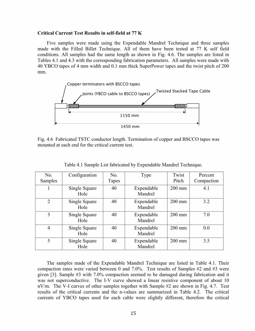
Five samples were made using the Expendable Mandrel Technique and three samples made with the Filled Billet Technique. All of them have been tested at 77 K self field conditions. All samples had the same length as shown in Fig. 4.6. The samples are listed in Tables 4.1 and 4.3 with the corresponding fabrication parameters. All samples were made with 40 YBCO tapes of 4 mm width and 0.1 mm thick SuperPower tapes and the twist pitch of 200 mm.
Fig. 4.6 Fabricated TSTC conductor length. Termination of copper and BSCCO tapes was mounted at each end for the critical current test.
Table 4.1 Sample List fabricated by Expendable Mandrel Technique.
No. Samples
Configuration No. Tapes
Type Twist Pitch
Percent Compaction
1 Single Square Hole
40 Expendable Mandrel
200 mm 4.1
2 Single Square Hole
40 Expendable Mandrel
200 mm 3.2
3 Single Square Hole
40 Expendable Mandrel
200 mm 7.0
4 Single Square Hole
40 Expendable Mandrel
200 mm 0.0
5 Single Square Hole
40 Expendable Mandrel
200 mm 3.5
The samples made of the Expendable Mandrel Technique are listed in Table 4.1. Their compaction rates were varied between 0 and 7.0%. Test results of Samples #2 and #3 were given [3]. Sample #3 with 7.0% compaction seemed to be damaged during fabrication and it was not superconductive. The I-V curve showed a linear resistive component of about 10 nV/m. The V-I curves of other samples together with Sample #2 are shown in Fig. 4.7. Test results of the critical currents and the n-values are summarized in Table 4.2. The critical currents of YBCO tapes used for each cable were slightly different, therefore the critical
1150 mm
1450 mm
Joints (YBCO cable to BSCCO tapes)
Copper terminators with BSCCO tapes
Twisted Stacked Tape Cable

16
current of the cable samples can differ from sample to sample, however the difference in n-value could be resulted from the cable fabrication method probably due to the compaction rates. From the results seen in Table 4.2, Sample #5 of compaction 3.5% seems to be the best. Sample #2 of compaction 3.2% showed a relatively good result as well as Sample #4 of zero compaction. Therefore we can conclude from this test that a compaction up to about 3.5% can be safely applied.
Fig. 4.7 V-I curves of TSTC samples fabricated with different compactions by the Expendable Mandrel Technique.
Table 4.2 Test results of fabricated 40-tape YBCO TSTC conductors.

17
Table 4.3 Sample List fabricated by Filled Billet Technique.
No. Samples
Configuration No. Tapes
Type Twist Pitch
Percent Compaction
6 Single Channel 60 Filled Billet 200 mm 0.0
7 Triple Y-Channel 60 Filled Billet 200 mm 0.0
8 H-Channel 40 Filled Billet 200 mm 0.0
Fig. 4.8 V-I curve of Sample #8 fabricated by the Filled billet H channel technique.
The three samples made with the Filled Billet Technique are listed in Table 4.3. Each sample had different configuration. Samples #6 and #7 were made of 60 YBCO tapes. At present our terminations were limited to a 50-tape cable, therefore only Sample #8 was tested. The V-I curve is shown in Fig. 4.8, and the critical current and the n-value are also given in Table 4.2. The results show relatively low n-values. However, the Filled Billet Technique seems to be the most promising method for a long cable fabrication. The Filled Billet Technique forms twisted slots before mounting the stacked conductors, and then the conductor is applied twisting while being inserted in the groove. In this way fabrication damages can be minimized. The Filled Billet Technique will be further investigated.
18
V. SUMMARY We have further explored a cabling concept of the Twisted Stacked-Tape Cable (TSTC) to
develop YBCO cable conductors for high field, high current magnet applications. Cable performances of TSTC conductors were experimentally and analytically evaluated.
1. A new magnet winding technique, Stacked-Tape Twist-Wind (STTW) of YBCO tapes using the Twisted Stacked-Tape Cabling (TSTC) concept has been developed. A pentagonal shape coil sample made of a 2.3 m long, 50-tape YBCO conductor was fabricated by this method, and tested.
2. Stability analysis was performed for various TSTC conductors. 3. Two industrial scalable approaches: (1) Expendable mandrel technique and (2) Filled
billet technique were developed by Supercon, Inc. 4. TSTC conductors fabricated using various industrially scalable methods by Supercon
were tested.
VI. REFERENCES [1] Makoto Takayasu, Luisa Chiesa, Leslie Bromberg, and Joseph V. Minervini, “Investigations
of HTS Twisted Stacked-Tape Conductor,” MIT PSFC report, PSFC/JA-11-4, March 25, 2011. http://www.psfc.mit.edu/library1/catalog/reports/2010/11ja/11ja004/11ja004_full.pdf
[2] Makoto Takayasu, Joseph V. Minervini, and Leslie Bromberg, “HTS Twisted Stacked-Tape Cable Development,” MIT PSFC report, PSFC/JA-11-10, May 31, 2011. http://www.psfc.mit.edu/library1/catalog/reports/2010/11ja/11ja010/11ja010_full.pdf
[3] Makoto Takayasu, Luisa Chiesa, and Joseph V. Minervini, “Conductor Characterization of HTS Twisted Stacked-Tape Cable,” MIT PSFC report, PSFC/JA-12-65, May 11, 2012. http://www.psfc.mit.edu/library1/catalog/reports/2010/12ja/12ja065/12ja065_full.pdf
[4] Makoto Takayasu, Franco J. Mangiarotti, Luisa Chiesa, Leslie Bromberg, and Joseph V. Minervini, “Conductor Characterization of YBCO Twisted Stacked-Tape Cables,” IEEE Trans. Appl. Superconduct, 23, 2013, to be published.
[5] A. Devred, “Future accelerator magnet needs,” IEEE Trans. Appl. Supercond., 15, pp. 1192–1199, 2005.
[6] T.A Painter, J.R. Miller, L.T. Summers, A. Bonito-Oliva, A.L. Devernoe, et al., “Progress in the manufacture of the cable-in-conduit Nb3Sn outsert coils for the 45 tesla hybrid magnet,” IEEE Trans. on Magntics, 30, pp. 2204–2207, 1994.
[7] T.A. Painter, private communication.