technology developments for deep underwater neutrino
TRANSCRIPT

Technology Developments for Deep Underwater Neutrino Telescopes
G. D. Hallewell+
Centre de Physique des Particules de Marseille (CNRS/IN2P3), France
+ member of the Antares Collaboration
Abstract
The July-2002 report of the High Energy Neutrino Astrophysics Panel (HENAP, [1]) recommended the construction ofa km3-scale Northern hemisphere neutrino observatory to complement a large-scale under-ice observatory (IceCube) inthe Southern hemisphere. Such an observatory would study cosmic neutrinos with energies in excess of a few hundredGeV, which arrive undeviated from a variety of galactic and extragalactic sources of astrophysical interest, and whichmight be produced in the possible annihilation of dark matter particles, including neutralinos.
Future developments in technology from that being presently implemented by the Lake Baikal, Nestor, and Antarescollaborations toward that necessary for a much larger km3-scale array are discussed. In January 2000, a part of the Nemocollaboration, engaged in studies for a km3–scale detector close to the Sicilian coast, joined Antares in the developmentof a 0.1km2 detector. The two collaborations have formed a common working group to coordinate the effort toward theconstruction of a km3- scale detector.
The great depth presents numerous technical challenges in the construction, deployment and interconnection ofsuch detectors, and may require the involvement of industrial contractors with experience in fields including deep-sea oilexploitation, submarine telecommunications cable deployment, underwater acoustic navigation and communication, andin the operation of manned or remotely-operated submarine vehicles. This paper reviews the status of some of thetechnologies for underwater neutrino detector arrays.
(1) Introduction and detection principles
Most of the existing models for neutrino production in astrophysical sources estimate from a few to tens of events peryear in a ~ km2 aperture detector for energies >1TeV. By concentrating the detection upon upward-going neutrinosoriginating in the hemisphere on the opposite side of the Earth to a deeply immersed detector, the Earth is used as ashield against cosmic ray induced background. Only a Northern hemisphere detector is capable of seeing such neutrinosfrom point sources in the central region of our galaxy.
Many of the principal characteristics of an underwater muon-neutrino telescope were evolved more than twenty yearsago in a series of workshops dedicated to the DUMAND concept, and were later implemented in the Lake Baikalexperiments (§2.2).
The deep-water detection of high-energy muon-neutrinos exploits three properties:i) the directional correlation of the muon and parent neutrino trajectories to within 0.7º for Eν>3TeV;ii) the unique upward-going directional signature of muons from cosmic neutrino interactions w.r.t. the vastly higher muon background from cosmic ray collisions in the atmosphere. Upward-going muons can only originate from local neutrino interactions: the Earth filters out all other particles;iii) the long range of muons in water and rock over the neutrino energy range of interest. Upward going muons may be
generated far from the instrumented volume and still be detected.
Fig. 1 Principle of detection of high energy neutrinos in an underwater neutrino telescope.

Figure (1) illustrates the detection principle. Accurate reconstruction of the trajectory of a neutrino-induced muon relieson tracking over many tens of meters and measurement of the arrival time of the UV-blue component of the _erenkovwave-front to nanosecond accuracy on photomultiplier tubes (PMTs) whose positions are known to better than 22cm(equivalent to 1ns in water).
The choice of the PMT array spacing depends on the absorption and scattering length in the local deep-waterenvironment, and to a lesser degree on the limit set by the chromatic dispersion in arrival time of the _erenkov photons.Due to the high purity of water at great depth, light absorption and scattering are small. However the detector is subjectto backgrounds from cosmic ray muons, luminescence from deep-water creatures, and from _erenkov light from the βdisintegration of 40K, present in sea salt. Only the Lake Baikal freshwater site is free of 40K background.
(2) Sites for underwater neutrino observatories
(2.1) Site selection criteria
The optimum site criteria for an underwater neutrino observatory are;i) closeness to the coast to ease deployment and reduce the expense of the power and signal cable connections to
the shore;ii) as great a depth as possible to reduce background from atmospheric muons, and to suppress their
misreconstruction as upgoing. As an example the Lake Baikal array at -1100m has identified 34 upgoing muonsfrom a sample of 5.3 107 events [2] - in good agreement with MC predictions: at -4000m however, the flux ofdown-going muons is smaller by a factor ~80;
i) good optical properties in water long absorption [>20m] and scattering [~50m] lengths1 for light in the range[350 < λ < 550nm]);
iv) low level of bioluminescence;v) low rates of biofouling (bacterial film deposition and marine life accretion) on optical surfaces;vi) low rates of sedimentation (for any upward-looking optical components);vii) low velocity bottom current (~few cms-1 max.), since bioluminescence and sedimentation are dependent on this
parameter.
The sites and layout of present and near-future underwater neutrino observatories are now considered.
(2.2) The Lake Baikal site and array
Experimental activity at the Lake Baikal freshwater site [figure (2)] spans a period of almost two decades[2]. The present(“NT-200”) detector, in operation since 1998, has an instrumented volume rising from a depth of 1.1km, around 3.6kmfrom the shore near the Southern end of the lake. It contains 192 PMTs in 96 coincident pairs attached along eight linessupported from the spokes and center of a heptagonal umbrella-like composite frame [figure (3)]. Each line is dividedinto “stories” containing two pairs of spherical optical modules separated in height by 6.25m. A fifth glass sphere holdsthe readout electronics of each storey.
Water transparency at 480nm is characterized by absorption (scattering) lengths of 20-24 m (30-70m) [2]. The highsedimentation rate at the site has necessitated the protection of upward-facing optical modules.
An extension to the detector (“NT-200+”) has been approved to equip three additional lines of 6 pairs of opticalmodules at distances of 100 m from the center of the NT-200 array[2]. Commissioning is planned for spring 2004, andwill enhance the fiducial volume to 0.01km3 for neutrinos with energy above 1014eV. The resulting detector will beconsidered as a prototype module for a 1km3-scale detector.
(2.3) The Nestor site and array
The Nestor array will be located near Pylos on the Greek Ionian Sea coast [figure (4)]. An electro-optical cable has beenlaid from a shore station at Methoni to a site at - 4100m around 15km from the shore. The array, shown conceptually infigure (5), will comprise a series of ‘towers’, each rising 360m from a seabed anchor, held in tension by an underwaterbuoy. Each tower will contain 144 PMTs mounted on 12 titanium-framed 32m diameter ‘floors’ in the form of six-pointed stars. A pair of PMTs will be mounted on each arm, one looking up, the other down. The array is intended tobe installed and extended without the need for underwater electro-optical connections by submarine vehicles. The waterin this region of the Ionian basin is very clear, with ~ 55m attenuation length [3] for blue light. Bottom currents havebeen measured to be below 10cms-1. Extremely low rates of sedimentation and biofouling permit a significant number ofupward-looking optical sensors.
1 The absorption coefficient a is defined as 1/La; the scattering coefficient b=1/Lb. Their combination, c = (La+Lb)/(La.Lb), is the attenuationcoefficient. Due to the combination of absorption and scattering phenomena, light intensity scales with distance L as I = (I0 /L2).e-cx.

Fig. 2 The Lake Baikal site
Fig. 3 The Baikal NT-200 array
Fig. 4 The Nestor site in the Ionian sea
Fig. 5 Conceptual layout of the Nestor array
The Nestor cable to shore was deployed in June 2000, but was damaged by the ship during the cable lay. In January2002 the end of the cable was recovered; the cable was repaired and redeployed at 4100m with an electro-opticaljunction box and associated instruments including an underwater current meter, an ocean bottom seismometer, anephelometer to monitor light scattering, temperature and pressure sensors, a compass and a tilt-meter. Instrument datahave been transferred to the shore for nearly a year; the first long-duration real-time data readout from a component ofdeep-sea neutrino detector.The planned deployment of the first detector floor in late 2002 was prevented by the onset ofbad weather. The collaboration hopes to do so soon. This set up will collect data and evaluate detector performance in

real conditions over a long period. Following this engineering run, a detector consisting of four floors will be deployedin spring of 2003 for more tests and physics data taking. The deployment of a full tower is foreseen during 2004.
(2.4) The Antares site and array
The Antares collaboration is constructing, with the participation of part of the Nemo collaboration, a 0.1 km2 aperturearray for operation at –2400m off the French Mediterranean coast near Toulon [figure (6)]. The detector is linked to ashore station at La Seyne sur Mer by a 40km electro-optical undersea cable2 laid in October 2001. The cable wasterminated in December 2002 with the deployment of the central electro-optical junction box. The array layout is shownconceptually in figure (7). The first phase detector implementation will have twelve detection lines spaced on a 60m seafloor grid, anchored to the seabed and tensioned by submerged buoys. The array will contain a total of 1080 PMTshoused in optical modules (§3.1), grouped in triplets at 30 levels rising from -2300m to -1950m.A series of site evaluation campaigns has been carried out by the Antares collaboration [4,5]. At the array depth of2400m, the expected background rate from atmospheric cosmic ray muons is around 30Hz. This rate is insignificant incomparison with the 40K β background from sea salt, which adds a singles rate of 60kHz to each 10 inch PMT, or withoccasional bio-luminescence [figure (8)], which can peak during short bursts up to MHz rates, and is seasonally andocean current dependent. Since the PMTs in the Antares array will be angled 45º downward toward the seabed, foulingis not a serious problem. The combined signal loss due to bio-deposition and sedimentation has been measured [4] tobe less than 2% per year.
2 Manufactured and deployed by Alcatel
Fig. 6 The Antares Mediterranean site Fig. 7 Artist’s impression of the Antaresunderwater neutrino detector array
.
Fig. 8 Background singles counting rate in a 10 inch PMT at the Antares site.
The attenuation and scattering lengths in water at the Antares site have been measured in several campaigns between1998 and 2000. At 466nm, attenuation [scattering] lengths have varied between 45 and 60m [37 and 79m]. The

seasonal variation in these figures is significant, and the Antares array will incorporate an “instrumentation” line whichwill deploy underwater instruments including transparency and current profile monitors.
The construction of optical modules for twelve detection lines is well advanced. The commissioning of a fullreadout chain is progressing; a pre-production “sector line” of five optical module triplets was deployed in late 2002following the deployment of the electro-optical junction box. A site instrumentation line will be deployed in early2003. The commissioning of a 0.1km2 array of twelve detection lines is planned for completion in 2004/2005.
(2.5) The Nemo site and array
The Nemo collaboration has identified a possible site for a km3-scale array at –3500m a distance of 80km from theSicilian coast near Capo Passero. [figure (9)]. At this location in the Ionian sea, bacterial concentration is relatively low,with the consequent advantages of low expected bioluminescence background and biofouling rate. Preliminary studiesover a period of 40 days have shown no evidence for biofouling. At the site, the light attenuation (absorption) lengthexceeds 35m (70m)[6]. The average bottom current is around 3cms-1, with a measured sedimentation rate of ~20mgm-
2day-1. It remains to be proven that this low rate would not seriously degrade the performance of upward-looking PMTsafter ~ 1 year, should the detector design include them.
The Nemo concept is for a 1km3-scale array with 4096 optical modules hung from 64 “towers” laid in a square gridwith 200m spacing. Each tower [figure (10)] would rise 750m from a seabed anchor, and would contain 16 “floors”separated in height by 40m, each with a pair of PMTs at each end of a 20m composite support arm. A matrix of supportcables would ensure that successive floors deploy orthogonally under the force of the suspension buoy
.
Fig. 9 The Nemo site South-East of SicilyFig. 10 Concept for a Nemo tower
(Courtesy N.Musumeci, INFN-LNS Catania
The Nemo collaboration has also brought into service a test site at a depth of 2031m. A 28km electro-optical cable fromCatania in Sicily [7] splits 23km from the shore, a second brach running 5km to the “Geostar” underwaterenvironmental platform. Each site is serviced by 10 optical fibers and 6 electrical conductors.
(3) Detector technology issues
In this section, the technology of underwater neutrino detectors is discussed in more detail.
(3.1) The optical detection modules.
As in existing water neutrino detectors such as Super-Kamiokande and SNO, _erenkov light will be detected usingPMTs with single photon sensitivity. The extreme pressure at the operating depths requires that the PMTs be housed inpressure resistant glass spheres. Such spheres are readily available in diameters up to 43cm with depth ratings up to7000m from several suppliers3 and may be purchased in a variety of glasses, including low potassium (low β activity)
3 (1) Benthos Corp, North Falmouth MA 02556 USA; Benthos type 2040-17V used in Nestor (2) “Vitrovex” ® by Nautilus Marine Service GmbH, D-28357 Bremen, Germany. Vitrovex type 8330 used in ANTARES (3) “EKRAN” (Novosibirsk) and Vitrovex used at Lake Baikal

variants. Spheres are supplied as matched hemispheres and can be predrilled with electrical and pump-out penetrations.Leaktightness at high pressures is given by plastic deformation of the ground glass contact surfaces of the hemispheres:no “O” ring joint is used.
Figure (11) illustrates the components of a generic optical module of an underwater neutrino detector. In Antares [8]and Nestor [9], the pressure spheres from different manufacturers exhibit very similar character-istics: 43 cm diameterwith 1.5cm thick, low activity (< 0.5% K content) borosilicate glass having n = 1.47 and transmission > 87% for λ >400nm. A PMT with single photon sensitivity is is shielded from the Earth’s magnetic field by a two part mu-metalwire cage, and is mounted and optically coupled onto one hemisphere using an index matching gel4.Since powerconsumption is critical in large detector arrays powered through very long shore cables, the HV bias for the dynodearray is usually generated in a custom PMT base from a DC input, using a Cockcroft-Walton chain. A light flashersystem consisting of a blue LED and pulser circuit may be added to monitor the PMT transit time, which can exceed60ns in large photocathode PMTs. The pulser trigger signal is referenced to the detector master clock.
Table (1) illustrates the performance of the Hamamatsu R7081-20 10-inch PMT used by the Antares collaboration.Its performance is fairly typical of PMTs used in deep-water neutrino detectors. The Nestor collaboration uses the 15-inch Hamamatsu R2018-02.
4 In Antares: “Silgel” ® 612 A/B by Wacker-Chemic GmbH, 81737 Munich, Germany: 2-component silicon rubber, room temperature cure: n = 1.404. [transmission > 88% for (400 < λ < 700) nm]:In Baikal, (Nestor); Wacker Semicosil gel n~1.4, (gel or liquid glycerine n=1.478) with polyeurathane (gel) containment gasket.
Fig. 11 A generic underwater optical module
.
Photocathode Sensitive area 500cm2
Combined efficiency(quantum ⊕ collection: 400 < λ < 700 nm)
> 16 %.
Gain @ 2500 V. 2 x 10⁸
Pulse amplitude @ Nominal working gain of 5 x 10760mV/50Ω
Transit Time ~ 60 ns
Transit Time Spread (TTS: FWHM) < 3 ns
Dark count rate (@ 0.3 * single P.E. threshold) < 10kHz.
Pulse Rise time < 5 ns
Pulse Width (FWHM: single P.E.) < 12 ns
Table (1) Parameters of Hamamatsu 7081-20 PM
The Lake Baikal collaboration adopted an innovative approach to the problem of cost of large PMTs[10,11]. In the‘Quasar 370’ hybrid [figure (12); after [10]], a 370mm diameter external dome containing a photocathode andelectrostatic focussing is used to generate and accelerate photoelectrons toward a disk of scintillator viewed by a small(“UGON”) PMT. The device is sensitive to single photoelectrons and has a transit time spread in the range 1-2nsFWHM, competitive with large “monolithic” PMTs. A Quasar tube with a twin-anode PMT with a mesh dynodestructure has been tested in the underwater array [12]. Inter-anode crosstalk was measured at 1-2%, and the muonsensitivity was comparable [12] to that of a coincident pair of single channel Quasar optical modules, [Figure (13)]. Thecollaboration has also developed a modification of the Quasar tube in which the scintillator and PMT are replaced by asemiconductor diode..

Fig. 12 Extended photocathode and electrostaticfocussing dome used in the Lake Baikal array.
. . Fig. 13 Upward-looking Quasar-type opticalmodules from the Lake Baikal array.
(Anti-sedimentation cones fitted.)A group in the Nemo collaboration [13] is investigating a similar hybrid device [figure (14)]. The dome features a Sb-K-Cs photocathode and 25kV focussing field onto a disk of YSO crystal scintillator.
Fig. 14 A possible extension of the “Quasar” concept to multiple PMTs.(Courtesy M.Battaglieri, INFN Genova)
The prototype is flanged together from two pieces (a), (b). Transit time (transit time spread) in the prefocusser are ~6ns(~1 ns). The incorporation of four miniature PMTs5 [(c), (d)] would afford a degree of rejection of dark current and 40Knoise through local coincidence, together with a degree of directional sensitivity missing in most present generationoptical modules.Other possible candidate photon detectors for optical modules include hybrid and avalanchephotodiodes and gas electron multiplication devices (GEMs). Their potential for a km3-scale detector must beevaluated.
5 Hamamatsu R6427 1 1/8”: QE 27% @ 420 Nm ; G ~ 3 106 @ 1500 V, Rise Time ~ 1.7 ns, FWHM ~ 0.5 ns

(3.2) Structural and pressure components
In the present generation of deep underwater neutrino arrays, the requirements of pressure and corrosion resistance havepredicated the almost exclusive use of glass and titanium for pressure vessels. Structural supports are in titanium orcomposites, which will offer important cost savings in km3-scale arrays. Figures (15, 16, 20 & 25) illustrate the use oftitanium in the Nestor and Antares optical module support frames, electro-optical junction box and triplet electronicshousing.
Each 32m-diameter Nestor titanium floor frame [9, 14] will incorporate a central titanium sphere containing dataacquisition, power conversion and monitor & control system electronics. The six arms are composed of folding 5mtubular frames as shown in figure (15).
Although uncoated ferrous-metal structures (including stainless steel) are unsuitable for use in deep-sea water,possible cost reductions relative to titanium might be achieved by decoupling the problems of pressure and corrosionresistance. Figure (17) illustrates a junction box being considered by Nemo [15] in which a main electro-optical cable issplit into parallel outputs for an array of detection lines. Cables exit the walls of the spherical steel pressure vesselthrough ‘penetrators’ and pass through an oil volume to terminate in underwater-mateable connectors arranged around thecircumference of an oil bath built in composite GRP. An internal flexible water bladder6 ensures the equipressure ofwater and oil by compensating the slight compressibility of the oil.
6 Manufactured for example by Pronal SA 59115 Leers, France
Fig. 15. Partially folded titanium frame of aNestor ‘floor’ (at Nestor Institute, Pylos)
Fig. 17 Example of an oil barrier/steel deep-seajunction box pressure vessel
(Courtesy N.Musumeci, INFN-LNS Catania)Fig. 16 Titanium optical module support frames
for ‘triplet’ stories of the Antares detector
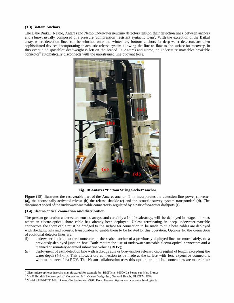
(3.3) Bottom Anchors
The Lake Baikal, Nestor, Antares and Nemo underwater neutrino detectors tension their detection lines between anchorsand a buoy, usually composed of a pressure (compression) resistant syntactic foam7. With the exception of the Baikalarray, where detection lines can be winched onto the winter ice, bottom anchors for deep-water detectors are oftensophisticated devices, incorporating an acoustic release system allowing the line to float to the surface for recovery. Inthis event a “disposable” deadweight is left on the seabed. In Antares and Nemo, an underwater mateable/ breakableconnector8 automatically disconnects with the unrestrained line buoyant force.
Fig. 18 Antares “Bottom String Socket” anchor
Figure (18) illustrates the recoverable part of the Antares anchor. This incorporates the detection line power converter(a), the acoustically activated release (b) the release shackle (c) and the acoustic survey system transponder9 (d). Thedisconnect speed of the underwater-mateable connector is regulated by a pair of sea-water dashpots (e).
(3.4) Electro-optical connection and distribution
The present generation underwater neutrino arrays, and certainly a 1km3-scale array, will be deployed in stages on siteswhere an electro-optical shore cable has already been deployed. Unless terminating in deep underwater-mateableconnectors, the shore cable must be dredged to the surface for connection to be made to it. Shore cables are deployedwith dredging tails and acoustic transponders to enable them to be located for this operation. Options for the connectionof additional detector lines are:(i) underwater hook-up to the connector on the seabed anchor of a previously-deployed line, or more safely, to a
previously-deployed junction box. Both require the use of underwater-mateable electro-optical connectors and amanned or remotely-operated submarine vehicle (ROV);
(ii) deployment of each detection line with a dredge able or bouy-anchor released cable pigtail of length exceeding thewater depth (4-5km). This allows a dry connection to be made at the surface with less expensive connectors,without the need for a ROV. The Nestor collaboration uses this option, and all its connections are made in air
7 Glass micro-spheres in resin: manufactured for example by BMTI s.a. 83500 La Seyne sur Mer, France8 Mk II Hybrid (Electro-optical) Connector: Mfr: Ocean Design Inc, Ormond Beach, FL32174, USA9 Model RT861-B2T: Mfr: Oceano Technologies, 29200 Brest, France http://www.oceano-technologies.fr

before deployment. However, the seabed becomes cluttered with very long cables and their descent needs to becarefully controlled to avoid damage to the already-deployed detector;
(iii) previously-deployed detection lines are recover-ed (buoy-anchor captive release) for a dry daisy chain connectionat the surface. No ROV required. Inter-line pigtails need to exceed the water depth. Cables and discarded anchorsclutter the detector area. Considerable risk of damage to already-deployed lines.
Electro-optical distribution is a significant component of the cost of undersea neutrino detectors, particularly where theshore link cable is long or custom. In an effort to minimise this cost, Antares (Nestor) have deployed standardtelecommunications cables with 48 (18) optical fibers and a single power conductor10. Figure 19 illustrates the (dry -mateable) electro-optical connector11 of the Antares undersea cable. The connector shell is titanium with an outerdiameter of 25cm. The four electrical contacts (in equipotential in the Antares cable) are grouped at the center. In bothdetectors, power returns to the shore station via a deep-sea electrode12 and a shore electrode located below the
Fig. 19 Example of a commercial (Dry-mate) undersea cable electro-optical connector(Photo courtesy Sea Con Inc.)
low tide level. Nestor uses monopolar DC while Antares will be powered with 4200V 50Hz AC at ~ 8A: a centraltransformer in an underwater junction box reducing and distributing the voltage to the detector lines. The majorconcerns with monopolar DC supply are the environmental impact of long-term underwater chlorine production and theeffects of corrosion and chemical attack on nearby detector structures.
The Antares 50Hz distribution system is rather conservative: for a km3-scale detector, R&D is required intodistribution at 400Hz, as in aircraft systems, since this would allow the use of lighter and more efficient transformers. Atthe Nemo test site the main electro optical cable splits into two drops, each with 10 optical fibers and 6 powerconductors [16], which will facilitate studies of a variety of AC and DC powering scenarios.
At the Lake Baikal array, the junction box is located over the detector. It is lifted every year during the winter iceseason for recovery and repair of damaged components. All connections are performed on the ice before re-immersion.
Figure (20a,b) show the Antares central junction box, based on a 1m diameter titanium sphere with a centralcylindrical connector belt through which enter the shore electro-optical cable, the sea electrode cable and 16‘penetrators’ with 2.5m electro-optical cable pigtails ending in underwater-mateable connectors. The junction box is
10In long undersea telephone cables, optical signal repeaters are often wired in series through the single power conductor: one (the other) endstation supplying a +ve (-ve) voltage w.r.t. the sea.11 Mfr: SeaCon/ Inc, El Cajon CA92020-1874, USA.12In Antares via a 40mm diameter Titanium bar anode: length 1.7m, with “KERAMOX®-MMO” coating. Mfr: Magneto Special Anodes BV,3125 BA Schiedam, Netherlands

installed in a titanium frame providing strain relief for the re-descent of the shore cable. The frame also contains anacoustic transponder13 to locate the junction box following deployment. Figures (20a, 21) illustrate the Ocean DesignMkII Hybrid connector receptacle14. The receptacle and cable mounting plug are oil-filled, with conductors and fiberends shuttered in the oil volume in the unmated condition. Upon connection, the shutters open and oil is displaced intobladders at the rear of the receptacle and plug.
13 Model ET861T by Oceano Technologies: 9kHz Ë 14kHz & v.v.14 Mk II Hybrid Connector, Titanium shell: (2 conductors, 4 fibers). Fiberoptic insertion loss <0.2dB, HV standoff (pin-shell) 500V unmated,1000V
mated. Mfr: Ocean Design Inc, Ormond Beach, FL32174, USA Rated > 100 insertions < 6000’ depth before oil refurbishment.
Fig. 20a Antares junction box with penetratorsand underwater-mateable connectors
Fig. 20b Antares junction box duringdeployment; illustrating acoustic transponder (top)
titanium support frame and undersea cableattachment.
The Antares junction box is the underwater hub of the detector, splitting the power between the detector lines,distributing clock signals and gathering the data signals from the detector lines onto the shore cable. Its 24kWtransformer has sixteen separate 500V secondaries to power and galvanically isolate each detection or instrumentationline. Each output may be switched on/off or reset by a remotely controllable circuit breaker handled via the triplyredundant junction box slow control system [figure (22)]. Passive fiberoptic splitters distribute the master clock signalsin duplicate to the sixteen output lines. Lines will be connected to the junction box as they are deployed, using aROV equipped with a manipulator arm.

Fig. 21 Hybrid underwater-mateable connectorreceptacle by Ocean Design Inc.
Fig. 22 Upper compartment of the Antares junctionbox: slow control cards, output circuit breakers
and current monitors.
Power arriving at a detection line from the junction box is converted from 500V AC to 380 V DC at the anchor [figure(16)] for passage up the cable to the thirty electronics containers. In these, it is further reduced via DC/DC converters foruse in optical modules and readout electronics. Very high reliability is required of critical underwater electronics andpower distribution components, [MTBF (mean time between failures) >> 10 year typical operational life], due to thevery high cost of recovery and repair of damaged components, particularly should submarine vehicles be required.In contrast to the situation with electro-optical connectors, a wider variety of underwater all-electrical or all-fiberconnectors exists.
Fig. 23 Part of the SeaCon “All-Wet”® range ofdry-mated underwater electrical connectors

Relatively inexpensive dry-mateable types for 500 bar + ambient pressure are available from several manufacturers.Figure (23) illustrates the “All-Wet” ® all-electrical series from Sea-Con Inc. The Nestor collaboration utilisesconnectors from the Gisma15 ranges.
(3.5) Readout systems
(3.5.1) General
The principal problem for the readout systems of undersea neutrino telescopes is the time-stamping and separation ofsingle photoelectron (SPE)-like PMT signals along muon trajectories from background due to 40K disintegrations andPMT dark current pulses and occasional bioluminescence. Bioluminescence pulses, due to their very large signal size,require considerably more bits to timestamp and digitise. These pulses often represent the main contribution to PMTdead time, but are usually correlated over only a few adjacent PMTs.
Data may be uploaded to the shore with or without the application of local (“off-shore”) triggering or localbioluminescence-rejecting coincidences. The “all-to-shore” option allows trigger decisions to be taken in on-shoreelectronics which can be upgraded to profit from technology advances during the lifetime of the detector.
(3.5.2) The Baikal data acquisition system
The Lake Baikal detector readout system is centred on local coincidences between adjacent optical modules [10], whichreduce the combined dark current and bioluminescence noise rate to 100-300Hz per coincident pair. The array has a singlephotoelectron background uniformly distributed in time, allowing the use of a less sophisticated data acquisition system.Signals from locally coincident PMTs are sent to an array trigger module and junction box sited above the detector[figure (3)] in which an overall trigger is formed and from which timestamps and digitised amplitudes are sent via wirecables to the shore. Due to the low rate, a simple muon trigger signal (e.g. ≥ 3 or 4 local coincidence hits within thearray in a 500ns window) [2] gives a sample nearly free of accidental coincidences.
(3.5.3) The Nestor data acquisition system
The Nestor readout [14] and data acquisition system (RDAQ) follows a data-driven architecture with waveform captureand capabilities for forming local (per floor) coincidences to reduce on-shore processing requirements.
Within the central titanium sphere of each floor, a “floor board” implements PMT pulse sensing, majority logicevent triggering, waveform capture and digitization for 12 PMTs. The board extracts data, formats events and transmitsdata via the single bi-directional optical fiber up/downlink per floor to the shore. Its FPGA/PLDs can be reprogrammedthrough the downlink.
The heart of the board is the four-channel “Analog Transient Waveform Digitizer” (ATWD) ASIC, developed atLBNL. Each channel contains 128 10-bit ADCs, which after activation simultaneously digitize 128 samples of aselected channel. At the chosen sampling rate of 282 MHz, each channel has a time range of 453 ns. One channel ineach ATWD is retained for synchronization, digitizing the waveform of a 40MHz clock signal. A “shore board” at theshore counting room, broadcasts a global 40 MHz clock signal via downlink to the floor board, receives the uplink dataand transmits them to the second level triggering system.
A “floor-trigger'' occurs when the programmed local coincidence requirement is satisfied on the floor. The time-stamp of a floor-trigger is defined as the leading edge of the majority logic signal, and the occurrence of such a triggerinitiates waveform capture by the ATWD. This time stamp will also be used at the shore to build a global eventcombining experimental information from several floors.
The performance of the RDAQ electronics and the online software has been extensively studied in the laboratoryusing an LED calibration system. The robustness of the system has been demonstrated under near-realistic immersionconditions at the Nestor Navarino Bay Test Station. The rms time stability of ATWD sampling at frequency of 282MHzhas been measured to be 6.4ps[14], negligible compared to the sampling period of 3.54 ns.
(3.5.4) The Antares data acquisition System
In the Antares array, the functions of the detector readout system are to time stamp (accepted) analog PMT signals, todigitize their charge, and to merge the data from the ninety PMTs on each detector line onto each single fibre-opticuplink to the shore station. The first stage of PM signal processing is performed by the Analog Ring Sampler (“ARS”)ASIC [17]; figure (24). The six ARS chips associated with each optical module triplet (two per PMT), are housed in
15 Mfr: Gisma D-24539 Neumuenster, Germany: http://www.gisma-connectors.de

a common electronics container [figure (25)] together with (depending on the position of the triplet along the detectionline), the compass and tiltmeter and/or hydrophone signal processing cards of the line positioning system (§3.6.2).
Fig. 24 Antares Analog Ring Sampler functionality
Fig. 25 Local electronics container(titanium) for the three optical modules of
an Antares “triplet”
The ARS ASIC is implemented in AMS 1.2 µm CMOS technology, and is based on a four-channel mixedanalog/digital pipeline memory. The ARS also implements a waveform shape-sensitive discriminator to distinguishsingle photoelectron-like (“SPE”) pulse shapes from superimposed pulses or from larger pulses characteristic ofbackground. The PMT direct anode signal enters one of the four inputs. Although each input can handle pulses up to4.5V, an attenuated anode signal, and a signal from the 12th dynode are used to extend dynamic range in the case oflarge signals. The distributed 20MHz master clock signal enters the fourth input. A signal from the PMT anode triggersthe ARS by crossing an amplitude threshold set to a fraction of the SPE average amplitude (the L0 threshold). Thesignal is time-stamped and its charge integrated to a precision of ~10% to compensate for time walk effects. A time tovoltage converter (TVC) interpolates between 20MHz clock pulses to give a time resolution of ~ 0.4 ns. Integratedcharge and timestamp are then stored in the mixed analog/digital pipeline memory. At the ARS output, an SPE tagconsists of a header (1 Byte), the integrated charge (1 Byte), TVC (1 byte) and the time stamp (3 Bytes).
In recent tests [18,19] with signals from a PMT illuminated with mainly single photoelectrons at a single point onthe photocathode, a time resolution of ~ 1.1ns has been achieved, comparing favourably with the PMT TTS of σ~1.3ns with full photocathode illumination. The intrinsic time resolution of the ARS was determined to be σ ~ 350psfrom measurement of the separation of two pulses injected into the ARS with a known time difference.
Analog pulse shape discrimination separates SPE pulses, which are charge integrated, from “waveform” (WF) pulseshapes, which are waveform-sampled in 128 samples at up to 1 GHz. This processing is implemented when the pulseheight exceeds several photoelectrons, when the time over the L0 threshold is longer than normal, or when the L0threshold is crossed more than once in the charge integration time. With 128 analog samples of the waveform, at theARS output, a WF event can typically contain > 250 bytes.
SPE events are expected to represent more than 98% of the Antares data, while WF events will be mainly generatedby background phenomena, primarily 40K disintegrations and bioluminescence. The pipeline memory of each ARS canstore up to 16 SPE hits or 4 WF hits.
With a singles rate of 70kHz, and 2% fraction of WF events, the (typical) data rate will be ~7Mb/s per PMT. TwoARS chips are connected to each PMT to reduce dead time. This data rate is shared between the (fast) output ports ofthe two ARSs and is well within the 20Mb/s bandwidth limit of each. The PMT readout system is intended to handlean average singles rate of up to 100kHz with surges of up to 250kHz due to bioluminescence bursts.
Data from five PMT triplets (five levels) will be merged onto a single descendant fiber with a typical bandwidth of105MB/s. Data from six such fibers will be DWD16-multiplexed onto a single fiber at the bottom of each detection line,
16 “Dense Wavelength Division”

resulting in a typical data rate to shore of 700MB/s per line. These fibres pass through the junction box and onto the40km electro-optical cable linking the detector array to the shore
An on-shore data switchyard will de-multiplex up to 70 incoming data streams and pass data to a processing farmconsisting of up to 100PCs running at an input data rate in the range 50-100MB/s.
(3.5.5) Nemo readout system R&D
The Nemo collaboration is studying a readout system for a km3-scale array of 4096 PMTs. An event rate of 50kHz perPMT (dark current + 40K + SPE signals + average bioluminescence contribution) has been assumed [16]. A PMTsignal-processing ASIC (“LIRA01”, built in AMS 0.35µm CMOS technology: [16]) with 3 channels of 256-deepswitched capacitor array analog memory and 200MHz sampling rate is under development. The ASIC channels samplethe PMT anode, a dynode and the 20MHz master clock. LIRA01 will also incorporate a twin threshold (0.25SPE,5SPE) discriminator trigger and single photon classifier. The ASIC is aimed at a temporal resolution of 300ps. TheDAQ output rate (after zero suppression and packing) is ~5Mbs-1 per PMT. Two LIRA ASICs will be used in eachoptical module: while one is sampling the PMT, the other will push data out towards a 20MHz sampling ADC.
A “synchronous digital hierarchy” (SDH) protocol is being considered for data transmission and reception. AnSTM-1 tributary: (up to 155Mb/s) might be used for the readout of a floor (4 PMTs) onto a single descending opticalfiber. In electronics at the tower base, the 16 floor STM-1 streams would be multiplexed onto a single optical fiberrunning the STM-16 protocol (up to 2.5GB/s).
The array power and readout architecture envisions 8 secondary junction boxes (SJBs) and a primary junction box(PJB) to which the shore electro-optical cable is connected. The principal data paths from the SJBs to the PJB follow astar network, with a redundant data ring between the SJBs. Data from each sub array of 8 towers would be DWD-interleaved17 in its SJB onto a single optical fiber, thence passing to the PJB (with the additional redundant highwaybetween SJBs), before being retransmitted onto the 100km shore electro-optical cable following a +17dBm amplifi-ication18.
(3.6) Underwater acoustic survey and navigation
The reconstruction of muon tracks in an underwater neutrino detector is based on precise measurements (~1 ns) of thearrival times of _erenkov photons at optical modules. This reconstruction requires knowledge of the positions of theoptical modules relative to each other, or more practically, with respect to fixed reference points such as the detector lineanchors. The precision of this spatial positioning should be better than the corresponding dispersive uncertainty in thearrival time of _erenkov light detection (e.g. ~1.6 ns over a typical flight distance of 40m in Antares). Since 1 ns isequivalent to 22cm of light travel path in water, the relative position of every OM should be known to ~ 10-20cm.
Since detection lines will be suspended between sea anchors and submerged buoys subject to movement by deepocean currents, the positions of individual optical modules will need to be regularly determined from measurements ofline curvature and twist. In Antares, the relative positions of the OMs will be obtained from fits to position datadetermined by two independent systems: a high frequency long baseline (LBL) acoustic system [19,20] and a series ofsemiconductor tiltmeter-compass sensors disposed along each detection line. The relative positions of the OMs willthen be deduced from this reconstructed line shape and from the geometry of the OM frame. Additionally, a network oflaser and LED beacons producing narrow, timestamped blue light flashes will be used to give redundancy in the on-linecalibration of PMT timing.
(3.6.1) The Antares acoustic positioning system
An array of four 40-60kHz acoustic transponders [20] 19[figure (26)], delineating a 300 x 300m LBL square, has beendeployed on the seabed at the Antares site. Additional transponders will be added (on sea achors) as detection lines aredeployed. The LBL transponders will transmit sound signals to hydrophones mounted at six positions (altitudes 100,184, 256, 328, 388 & 448m) along each detection line. The 3D positions of the hydrophones will be obtained bytriangulation. The sea bed transponders will interrogate each other and the seabed anchors to determine their relativepositions.
17 Candidate device: AWG/CI008 by E-Tek Dynamics18 Candidate device: type 1738U Erbium-doped Fiber Amplifier by Agere Systems19 Mfr: Genisea/ECA, 83078 Toulon, France: Frequency range 44-60kHz, 2kHz channel spacing

Fig. 26 Deployment of the acoustic transponders of the Antares long baseline survey system
Figure (27) illustrates a recent implementation of the acoustic survey system with rangemeter hydrophones at threeelevations on a deployed line. The precision of vertical height measurement between two hydrophone rangementers wasmeasured to be better than 5cm [figure (28)]. The transmission and reception of each sound pulse must be time-referenced relative to the master clock signal used to time stamp PMT data. The conversion of acoustic transit timesto distances requires accurate knowledge of the sound velocity within the detector. This in turn depends on thetemperature, salinity and pressure [21]. Instrumentation to monitor these parameters will be needed, and has beenextensively studied in the Antares-Nemo collaboration. These instruments are included on a dedicated instrumentationline.
Fig. 27 Illustration of relative positions ofhydrophone rangefinders and transponders
Fig. 28 Time variation of vertical displacementbetween hydrophone rangefinders due to deep
ocean current
(3.6.2) Semiconductor tiltmeter/compass systems
The detection lines of Antares will incorporate combined bi-axial tiltmeter and compass sensors20 [figure (29)] to givethe local tilt angles of each OM triplet level with respect to the horizontal plane (range [precision]; ±20° [±0.2°] inpitch and roll), as well as its orientation relative to Earth Magnetic North (heading range [precision]; 0-360° [±0.5Ë1°]), caused by cable torsion.
20 Model TCM2-20: Mfr: Precision Navigation Inc., Santa Rosa CA95403, USA http://www.pnicorp.com

The performance of the positioning system has been studied in various configurations (varying the number ofacoustic sensors and tiltmeters; the locations and precision of sensors, positions of missing sensors etc.), with differingvalues of deep water current and detector line twist as a function of altitude. These studies indicate that the proposedcombination of acoustic triangulation and tiltmeter-compasses should allow the positions of all OMs to be determinedwith an accuracy σ < 10cm in deep water currents up to 15cms-1.
Fig. 29 Antares combined tiltmeter-compass card
(3.7) Site evaluation and underwater environmental instrumentation
Nemo, Lake Baikal and Antares have a common program of site measurements and instrument cross calibration [6,22].Some instruments have been used at all three sites. Additionally, many of results from the instruments used in sitecharacterisation are of interest to the oceanographic, deep-sea biology and geophysics communities. The Nestorcollaboration has, for example, been acquiring real-time seismograph and ocean current data at its Ionian sea site sinceJanuary 2002. The Nemo test site lab at Catania will acquire real-time data from the GEOSTAR-Poseidon underwaterseismic station.
One output of the Antares junction box (2 conductors @ 500V AC, and 4 optical fibers; DAQ Tx, Rx and 2carrying GPS-referenced clocks) will be made available for oceanographic collaborators, while on another output acomprehensive array of environ-mental monitoring instruments for the Antares site, some developed by the Nemocollaboration, will be incorporated onto a dedicated instrumentation line.
(3.7.1) The Antares instrumentation line
One of the sixteen junction box outputs will be reserved for an “instrumentation line” containing equipment formonitoring the detector array and deep-sea environmental parameters including salinity, sound velocity, watertransparency and current profile. For detector-wide timing calibration, a laser beacon will illuminate the array with fast(900ps), time-stamped laser21 pulses at a wavelength of 456nm. Its action will complement shorter-range blue LEDbeacons distributed among the detection lines.
21 Incorporating a NG-10120-120 laser head.Mfr Nanolase, 38941 Meylin, France

Fig. 30 Configuration of a prototype instrumentation line to be deployed at the Antares site.
The deep-sea current profile (velocity, direction) will be sampled over 256 intervals over the full detector depth of 300mby a pair of 300kHz acoustic Doppler current profilers22 with a velocity range [resolution] of 5 ms-1 [1 mms-1].
The optical attenuation of water at 470nm will be measured over a 25cm path length using a commercialphotodiode-based water transmission meter23. The line will be equipped with sound velocity meters of the same type asinstalled close to the sea anchors of some detection lines. These devices24 have a flight path of 20cm and a precision of± 0.05ms -1 for typical velocities in the range 1400-1600ms-1. Several velocity meters will also be equipped withconductivity-temperature25 and depth (pressure) probes26. A seismometer will also be connected to the instrumentationline. A preliminary version of the instrumentation line with a single current profiler [figure (30)] will be deployed inearly 2003.
(4) Acoustic detection of neutrinos
Several groups in Europe and worldwide are pursuing the acoustic detection of neutrino interactions. Very high-energy(~10PeV) neutrinos generate a cascade of secondary particles through e-m or hadronic showers produced in theirinteractions with water. Secondary ionisation induces local heating of the water, generating a corresponding pressureinduced sound pulse, which may be detected (triangulated) with a sufficiently sensitive hydrophone (array). Theproduction of a sound pulse is illustrated in figure (31).
Such acoustic detection would exploit the much longer attenuation length of sound, than light, in water. Soundpulses around 400m from a 10PeV cascade at a depth of 4km should give bipolar sound pulses with amplitude varyingbetween 8 and 70µPa (depending on the theoretical model assumed), with duration in the range 60-80µs. By way ofreference, the human ear is sensitive to sounds of ~25µPa @ 1kHz.
The Lake Baikal collaboration has installed a hydrophone [2] for use in correlating the arrival of extensive airshowers with a surface (ice) scintillator array and the NT-200 underwater optical detectors. A group from the Nemocollaboration will install four hydrophones27 at the Nemo test site near Catania [23].
Optical encoding of the hydrophone signals will take place at depth for transmission through the 28km shore cablewith continuous data transmission at 96K * 24 bit samples per second.
22 Workhorse Monitor; Mfr: RD Instruments, San Diego CA 92131 USA23 C-STAR by WETlabs Inc. http://www.wetlabs.com24 Mfr: Genisea, France: model QUUX-3A(A):25 OEM-OT sensor by Falmouth Scientific Inc., Cataumet, MA02534, USA http://www.falmouth.com precision ±0.001mScm-1
26 Mfr: Druck S.A., 92600 Asnières sur Seine, France27 TR4037 by Reson 1-80kHz, omnidirectional, 1VµPa-1 @ 250Hz : a custom development, 2500m depth rating

Fig. 31 Acoustic pulse formation by high energy shower associated with very high energy muon(Courtesy G. Riccobene, INFN-LNS Catania)
The installation will be used for extensive studies of underwater noise, indispensable precursor data to determinewhether high-energy neutrino-induced sound signals can be separated from the oceanic acoustic clutter. Additionally,this installation will have considerable interdisciplinary interest since it should be able to detect the passage of whaleswithin a range of 10 miles, and of dolphins at larger ranges. A group from the Antares collaboration has begun studiesof the readout of hydrophones in an existing array near the Antares site. It is further planned to mount hydrophones ontwo Antares detection lines.
Further afield, a program of study has begun at the AGAM submarine detection array near Kamchatka, whichcontains 2400 hydrophones in a (102 x 17.3 x 4.5) m array. Other tests will be made at the AUTEC (Atlantic UnderseaTest and Evaluation Center) 52-sensor array off the Florida Caribbean Coast.
(5) Deployment and recovery considerations
The Lake Baikal detector site allows deployment and recovery operations to be carried out from the winches deployedon the winter ice cover. Figure (32a,b) shows the deployment of elements of the NT-200 composite support frameduring deployment. All electro-optical connections are made on winter ice before immersion.
Table (2a,b) illustrates the equipment necessary in the deployment of a scalable underwater array centred around ajunction box linked to a shore cable. Connections of underwater detection lines are assumed to require the plugging ofcables with underwater-mateable connectors through the use of a manned submarine or ROV. Table (2a,b) is based onthe Antares experience. In all cases, an already-deployed seabed acoustic transponder net and a ship with a GPS-referenced dynamical positioning system are required. Objects to be deployed on the seabed are equipped with their ownacoustic transponders, allowing their positions to be triangulated with respect to an already deployed acoustictransponder net, of which the Antares LBL is an example. During the deployment of the Antares junction box at a depthof 2400m, the undersea electro-optical cable was first located through shipborne interrogation of the acoustic transponderattached to its 400m long dredging tail. Movement of this transponder confirmed when the lowered grapple hadsuccesfully snagged the dredging tail. The descent of the junction box to the seabed was monitored in real time bytriangulation [figure (33)] of the position of its indivual acoustic transponder relative to the deployed net. In figure (33)

Fig. 32a,b Deployment of elements of the Baikal NT-200 support frame
Table 2a Deployment resources required
Underwater resource required
DeployedObject
DifferentialGPS/
AcousticNav
Grapple SubmarineVehicle
Shore-SiteE/O
Cable+transponde
r
YES NO NO
JunctionBox+
transponder
YESYES:
For Shore-siteE/O cable
dredging tail
NO
DetectionLine+
transponder
YES NO NO
Line- JBcable
connectYES NO YES
Table 2b Recovery resources requiredUnderwater resource required
DeployedObject
DifferentialGPS/
AcousticNav
Grapple SubmarineVehicle
Shore-siteE/O Cable
(for JBattachment
)
YESYES:
For Shore-siteE/O cable
dredging tail
NO
JunctionBox+
transponder
YESYES:
For JB dredgingtail
YES:Unplugging
Line- JB E/Oconnectionlines at JB
DetectionLine
(anchorabandonedon seabed)
YES NONO
Line E/Oplug auto-disconnect
Line- JBE/O cable
YES NO YES
In figure (33) the most recent position of the junction box is shown by a rectangle, while previous positions (at differingheights) are indicated by red spots. During the descent, the dynamical positioning ship adjusted its position 2.5kmalong the track of the undersea cable as 2.5km of cable were re-laid on the seabed with the junction box attached.
Fig 33. Acoustic transponder positioning of the Antares junction box during descent to seabed.

By contrast, the Nestor array will be deployed without the need for ROVs to perform underwater cable connections.Several times in tests the collaboration has deployed and recovered payloads composed of its base station and severalfloors from a depth of 4000m using cable-laying ships or platforms. The collaboration is constructing a highlyspecialised deployment platform. The self-propelled and ballasted platform [figure (34)] has an equilateral triangular formof side 51m, with a central well. It will be equipped with a GPS-related dynamical positioning system capable ofmaintaining its position at sea to a precison of several meters, and can be used to deploy structures with diameters aslarge as 100m.
Fig. 34 Nestor deployment platform. Fig. 35 Nestor tower recovery procedure.
Figure (35) illustrates the Nestor deployment/recovery concept [24]. Using a 5000m neutral buoyancy [“RecoveryRope” (ReRo)] rope, the Nestor tower is lowered to the sea bottom and the ReRo is laid across the sea floor with ananchor and buoy at its end. When the anchor is released with a coded acoustic signal the buoy floats to the surface andthe tower can be recovered and raised to the surface by winching on the ReRo.
6) Conclusion and km3-scale detector outlook
The Nestor and Antares projects have finished their underwater site evaluation and instrumentation development, andhave entered the construction and deployment phase. The Nemo collaboration has established a test site near Cataniaand has identified a site at a depth of 3000m that appears suitable for a km3-scale array. The Antares and Nemocollaborations are working together to build a first generation detector at the Antares site. Lake Baikal andAntares/Nemo have a common program of on-site measurements, while Lake Baikal and Nestor collaborate on variousengineering issues.
The Lake Baikal, Nestor and Antares projects can be thought of as developmental platforms for a km3-scaleunderwater neutrino array. They demonstrate that the technological building blocks for such a detector exist at thepresent time. However much R&D will be needed in the coming years to effect component cost reductions to allow theconstruction of a much larger Northern Hemisphere array. Some of this R&D has been started within the Nemocollaboration. The participation of industrial suppliers of telecom-munications equipment, undersea telecommunicationscable and underwater-mateable connector technology, manufacturers and operators of submarine ROVs, and supportvessels are all essential to the implementation of such a huge underwater assembly. The provision of space and servicesfor undersea oceanographic, geophysical and deep-water biology instrumentation will be vital to the interdisciplinaryappeal of such a project.
The development of acoustic detection systems, making use of the much longer attenuation length of sound in deepwater might provide a useful adjunct to a km3-scale detector, perhaps facilitating the search for ultra-high energy(>10PeV) neutrinos.
Acknowledgements
I thank my collaborators from the Antares and Nemo collaborations for their permission to quote from hithertounpublished R&D, and to the Lake Baikal and Nestor collaborations for information, some unpublished, on thatdetectors.

References
[1] “High Energy Neutrino Observatories”;Report of the High Energy Neutrino Astrophysics panel to PaNAGIC Committee: HENAP REPORT 1-July 2002
[2] B. Lubsandorzhiev; “The Lake Baikal neutrino experiment: present status and future prospects”:Proc. 2002 Workshop on Ring Imaging _erenkov Detectors (RICH 2002), Pylos, Greece, June 2002, to be published in Nucl. Instr. & Meth. A
I Belolapitikov et al; “The Baikal underwater neutrino telescope: design, performance and first results”;Astroparticle Physics 1997, Vol 7, p 263
[3] E. Anassontzis et al ; “Light transmissivity in the Nestor site”: Nucl. Instr. & Meth. A 349 (1994) 242 [4] P. Amram et al; “Sedimentation and fouling of optical surfaces at the Antares Site”; June 2002, submitted to Astroparticle Physics astro-ph/0206454[5] P.Amram et al; “Background light in potential site for the Antares undersea neutrino telescope”; Astroparticle Physics 13 (2000) 127-136 [6] A. Capone (INFN-ROMA 1); “Nemo Activities on Site Selection and Characterization” Antares collaboration
meeting, Catania, Italy 24-28/9 2002[7] M. Sedita (INFN-LNS, Catania); “km3 Cabling, connection and data transmission development” ibid[8] P. Amram et al; “The Antares optical module”; Nucl. Instr. & Meth. A 484 (2002) 369[9] E. Anassontzis et al ; “The optical module for the Nestor neutrino telescope”: Nucl. Instr. & Meth. A 479 (2002)439[10] R. Bagduev et al; “The optical module of the Baikal deep underwater neutrino telescope” Nucl. Instr. & Meth. A
420 (1999) 138[11] V. Balkanov et al; “Search for neutrinos from the core of the Earth with Baikal underwater detector NT-36”:
Proc 25th International Cosmic Ray Conference, Durban, South Africa July28-August 8 1997: Vol. 7, p269[12] B. Lubsandorzhiev ; “New developments of Photodetectors for the Lake Baikal neutrino experiment”:
In press physics/0208008 2 Aug 2002[13] M. Battaglieri (INFN-Genova); “Development of a hybid PMT”, Antares collaboration meeting, Catania, Italy
24-28/9 2002[14] S. Tzamarias et al: “Nestor: A deep sea neutrino telescope”:
Proc. 2002 Workshop on Ring Imaging _erenkov Detectors (RICH 2002), Pylos, Greece, June 2002, to bepublished in Nucl. Instr. & Meth. A
[15] N. Musumeci (INFN-LNS, Catania); “Goals of mechanical development for km3-scale detector”, Antarescollaboration meeting, Catania, Italy 24-28/9 2002
[16] L. Lo Nigro (INFN, Catania): “Technical solutions for the electronics and data transmission” ibid [17] F. Druillole et al; “The Analogue Ring Sampler: An ASIC front-end for the Antares neutrino telescope”: Proc. IEEE Nuclear Science Symposium, 4-10 Nov 2001, San Diego, CA, USA[18] F. Feinstein; “The Analogue Ring Sampler: a front-end chip for Antares”
Proc.3rd Baune Conference on new developments in photo-detection, Baune, France, June 17-21 2002; to bepublished in Nucl. Instr. & Meth. A
[19] G. Hallewell; “Status of the Antares underwater neutrino telescope”Proc. 2002 Workshop on Ring Imaging _erenkov Detectors (RICH 2002), Pylos, Greece, June 2002, to bepublished in Nucl. Instr. & Meth. A
[20] V. Bertin, Genisea ; “Système de positionnement acoustique base longue: Description technique” Antares report3INS0103B, May 2000
[21] C. Chen and F. Millero; “Speed of sound in sea water at high pressures,”J. Acoust. Soc. Am., Vol. 62, No. 5, 1129-1135, Nov 1977
[22] J-P. Schuller (CEA Saclay); “Some Antares results from Common Campaign with Nemo” Antares collaboration meeting, Catania, Italy 24-28/9 2002[23] G. Riccobene (INFN-LNS, Catania); “A deep sea station for the on-line monitoring of acoustic noise at the Nemo
test site.” Ibid[24] L. K. Resvanis: “ High energy neutrino experiments” Proc. XII international symposium on very high energy
cosmic ray interactions, CERN 15-20 July 2002 via http://www.nestor.org.gr /XII/index.htm