tek-care nc150 and nc200 intercom nurse call systems
TRANSCRIPT
Tek-CARE® NC150 and NC200Intercom Nurse Call Systems
UL® 1069 Listed
Operation, Installation and Service Manual
Tek-CARE® NC150 and NC200 series Intercom Nurse Call Systems are designed for nursinghome or individual hospital ward use. The Tek-CARE® NC150 and NC200 systems provideselective two-way audio and visual communication from master station to staff and patientstations, as well as emergency signaling and call indication from remote locations.Emergency calls are indicated by a rapid pulsing of all audible and visual signals associatedwith the calling station. Emergency calls take precedence over normal calls and can onlybe canceled at the point of origin.
IL380SECTION ERev. 20 - 03/2011
Distributed by:
Alpha Communications®
42 Central DriveFarmingdale, NY 11735-1202Phone: (631) 777-5500Fax: (631) 777-5599
Website:www.AlphaCommunications.com
Email:[email protected]
TOLL-FREE Technical #:1-800-666-4800

ii • IL380 Tek-CARE® NC150 & NC200 Manual Copyright © TekTone Sound & Signal Mfg., Inc. All Rights Reserved.
Operation, Installation and Service ManualCopyright © 2001–2011 TekTone® Sound & Signal Mfg., Inc., All rights reserved.
No part of this publication may be copied without the express written permission of TekTone® Sound & Signal Mfg., Inc. Thecontent of this manual is furnished for informational use only, is subject to change without notice, and should not be construed asa commitment by TekTone® Sound & Signal Mfg., Inc. TekTone® Sound & Signal Mfg., Inc. assumes no responsibility or liabilityfor any errors or inaccuracies that may appear in this documentation.
TekTone, the TekTone logo, Tek-Call, Tek-Care, Tek-Check-In, Tek-Com, Tek-Digicare, Tek-Door, Tek-Entry III, Tek-Guard, Tek-Micro, Tek-Micro II, Tek-MMARS II, TekNIOS, TekNIOS II, Tek-Paging, Tek-Phone, Tek-Safe, Tek-Select II, Tek-Sentry, Tek-Sound, Tek-Status, Tek-Trio and Tek-View are either registered trademarks or trademarks of TekTone® Sound & Signal Mfg., Inc.in the United States and/or other countries. All other trademarks are the property of their respective owners.

IL380 Tek-CARE® NC150 & NC200 Manual • iiiCopyright © TekTone Sound & Signal Mfg., Inc. All Rights Reserved.
A Word About ESD (Electrostatic Discharge) ....................................... iv
System Operating Instructions ...............................................................1NC150N, NC200N Master Stations ........................................................................... 1IR150B Staff Stations ................................................................................................ 3IR151B, IR152B Patient Stations .............................................................................. 5IR155B Patient Stations ............................................................................................. 5SF155B Emergency and SF156B Code Stations ....................................................... 5LI150B Duty Stations ................................................................................................. 5LI381 Corridor Lights ................................................................................................ 6LI382 & LI382LED Corridor Zone Lights ................................................................ 6
System Installation ...................................................................................7Installation Procedure ................................................................................................. 7Equipment Locations .................................................................................................. 7Wiring Installation ..................................................................................................... 8Housing Installation ................................................................................................... 9Wire Checkout .......................................................................................................... 10Wire Connections .................................................................................................... 10Connections Checkout .............................................................................................. 11System Test Instructions ........................................................................................... 11System Checkout and Testing .................................................................................. 11
System Maintenance Instructions ........................................................ 13NC150N, NC200N Master Stations ......................................................................... 13PK151A, PK152 Power & Control Units ................................................................ 14IR150B Staff and IR155B Patient Stations .............................................................. 14PK800A Secondary Power Supply ........................................................................... 14FZ151 In-Line Fuse Holder ...................................................................................... 14IR151B, IR152B Patient Stations ............................................................................ 15SF155B Emergency and SF156B Code Stations ..................................................... 15LI150B Duty Stations ............................................................................................... 15LI381 Corridor and LI382 Corridor Zone Lights ................................................... 15Replacement Parts .................................................................................................... 16
Illustrations & Wiring DiagramsFigure 1—NC150N and NC200N Control Locations ................................................ 2Figure 2—Duty, Staff, Patient, Emergency & Code Station Control Locations ........ 4Figure 3—Master Panel Housing Chart and Wall Cut-Out Details ......................... 8Figure 4—Panel Removal and Replacement ............................................................. 8Figure 5—Ring and Back Box for IR150B, IR151B, IR152B and IR155B ............. 9Figure 6—Ring and Back Box for SF155B, SF156B, LI150B,
LI381, LI382 and LI382LED .............................................................................. 9Figure 7—SS106 Transformer Installation ............................................................. 10Figure 8—NC150N, NC200N Selector Lamp/Switch
Lens, Filter and Lamp Replacement ................................................................. 13Figure 9—NC150N, NC200N Nurse Call Systems Notes and Electrical Ratings . 17Figure 10—Block Wiring Diagram without Zone Lamps ..................................... 18Figure 11—Block Wiring Diagram with Zone Lamps............................................ 19Figure 12—NC150N, NC200N Wiring Diagram ................................................... 20Figure 13—NC150N, NC200N, Two Stations in Parallel ....................................... 21Figure 14—PK153 Wiring Diagram with Smoke Detector .................................... 22Figure 15—PK153 Wiring Diagram with SF156B Code Station ........................... 23Figure 16—PK151A or PK152 to PK800A Interconnection .................................. 24Figure 17—SK151N Switch Board PCB Assembly ................................................ 25Figure 18—SF337C Cross Reference Diagram ....................................................... 26Figure 19—SF339 Cross Reference Diagram.......................................................... 27Figure 20—NC110N Hookup to NC150N, NC200N .............................................. 28
Table of Contents ————————————————————

iv • IL380 Tek-CARE® NC150 & NC200 Manual Copyright © TekTone Sound & Signal Mfg., Inc. All Rights Reserved.
What Is It? Static electricity is a result of triboelectric charging of two dissimilarnonconductive materials that are rubbed together, such as rubbing your feet on a carpet ona cold winter day or in a dry climate. The resulting charge is detected when you reach outto touch a doorknob or some other metallic object. The resulting discharge may only bestartling or, in severe cases, it may even be painful. The actual electrical charge is dependanton the materials being rubbed together, humidity, the rate of separation, and other factors.
What Can It Do? While this effect may be disturbing to humans, the effect on electronicequipment is often more serious, ranging from operational disruption to actual componentdamage. These effects result from the high voltages that may be developed. The simple actof walking across a carpet may develop as much as 30,000 volts, and changing a bed sheetmay create a charge of 100,000 volts or more. Such voltages readily cause arcing (thespark that can be observed when you grab a doorknob after walking across a carpet, etc.).The arcing is evidence of the discharge path. Due to the high voltage involved, the dischargecurrent can jump to any nearby metallic or non-metallic object. If the discharge is to orthrough an electronic device, such as the nurse call system, the operation of the device maybe affected. If the discharge current passes through internal components, these componentsmay be damaged or their operation degraded.
What Can We Do About It? The manufacturer of the nurse call equipment has alreadytaken steps to protect the equipment from electrostatic discharge (ESD) effects. However,since the cause is not in the equipment, but in the environment, further measures arerequired of the installer and the user to achieve complete protection.
What The Installer Can Do: In humid climates or in places where the relative humidity iskept at 65% or greater, there will likely be few problems with ESD. Where problems mayoccur the following measures can be taken.
• Ground all exposed metal surfaces. Grounding should be to a #16 gauge or largerconductor.
• Install nurse call system wiring in metal conduit. This conduit may be used to groundpanels.
• Use shielded cable for nurse call system station-to-station wiring. The use of openconductors invites inductive coupling of discharge currents, which can cause thesame problems as direct discharge currents.
• Ground your body before handling system components. This can be done by using awrist strap, or simply by contacting a grounded metal surface. Use caution to avoidhazardous voltages while grounded.
What The User Can Do: The most common generation of ESD in hospitals is due tochanging linen on hospital beds while the patient call cord or pillow speaker is still connectedto the nurse call system. The following precautions will help.
Remove the call cord or pillow speaker from the bed before changing the linen. It will benecessary for the nursing staff to discharge themselves by contacting a grounded metalobject before placing the call cord or pillow speaker back on the bed; otherwise a spark willjump to the nurse call equipment, causing the very damage they are trying to avoid. Toavoid a shock while discharging static electricity on the body, hold a metal object, such asa key, and use that object to contact the grounded surface.
This information is provided to make you aware of ESD problems so that precautions maybe taken to avoid damage and disruption of system operation.
A Word about ESD (Electrostatic Discharge)————————

IL380 Tek-CARE® NC150 & NC200 Manual • 1Copyright © TekTone Sound & Signal Mfg., Inc. All Rights Reserved.
This section provides complete operating instructions for all Tek-CARE® functions, aswell as reference drawings for use in locating and describing all controls. System operatorsmust read the following operating instructions concerning system equipment and the termsused in conjunction with the equipment.
NC150N, NC200N Master Stations
Refer to Figure 1 for locations, names, and functions of controls and indicators.
Answer Normal Calls:Normal calls are indicated by simultaneous operation of the following signals:
• Steady illumination of the associated station selector lamp which is marked toindicate call origin.
• Steady illumination of call lamp.
• Slowly pulsing audible tone. The audible call signal may be canceled for normal callsby pressing the TONE OFF button. The button will then illuminate to indicate the toneis silenced. Pressing the TONE OFF button when illuminated resets the call tone.
To establish conversation with the calling station, press the associated station selectorbutton. The remote station’s RESET lamp will illuminate. To speak to the caller, pressthe TALK button while speaking and release to listen.
When the conversation is complete, press the associated station selector button to releasethe station. The remote station’s RESET indicator will turn off. Normal calls placed froman IR155B Station must be canceled at the point of origin.
Answer Normal Calls Using Optional TA150N or TA200N Handset:To establish conversation with the calling station, press the associated station selectorbutton. The remote station’s RESET lamp will illuminate. To speak to the caller, lift thehandset from the cradle and begin normal two-way conversation. When the conversationis complete, press the associated station selector button to release the station. The remotestation’s RESET lamp will turn off. Replace the handset in the cradle. Normal callsplaced from an IR155B Station must be canceled at the point of origin.
Answer Emergency Calls:All emergency calls take precedence over any normal call signal. Emergency callsmust be answered in person and can only be canceled from point of origin. Emergencycalls are indicated by simultaneous operation of the following signals:
• Rapid flashing of the associated station selector lamp, which is marked to indicatecall origin.
• Rapid flashing of call lamp.
• Rapidly pulsing audible tone.
Answer Code Calls:All code calls take precedence over any normal or emergency call signal. Code callsmust be answered in person and can only be canceled from point of origin. Code callsare indicated by simultaneous operation of the following signals:
• Very rapid flashing of the associated station selector lamp (twice the rate ofemergency call), which is marked to indicate call origin.
• Very rapid flashing of call lamp (twice the rate of emergency call).
• Very rapidly pulsing audible tone (twice the rate of emergency call).
System Operating Instructions ——————————————

2 • IL380 Tek-CARE® NC150 & NC200 Manual Copyright © TekTone Sound & Signal Mfg., Inc. All Rights Reserved.
Figure 1—NC150N and NC200N Control Locations
1 – Duty Button: Transfers call tones from master station to a selected patientstation when pressed.
2 – Tone Off Button: Silences normal call tone when depressed.– Tone Off Lamp: Indicates tone silenced when illuminated.
3 – Call Button: Tone call to selected remote when pressed.– Call Lamp: Indicates incoming call when illuminated. Indicates emergency
call when flashing.
4 – Talk Button: Talk when pressed. Listen when released.
5 – Station Selector Buttons (PM150/4N): Establishes conversation path withassociated remote station when depressed.
– Station Selector Lamps: Indicates incoming call from associated remotewhen illuminated. Indicates emergency call from remote when flashing.
6 – Lamp Test Button (ST005D): Illuminates all lamps on panel when pressed.
7 – Telephone Handset (TA150N option): Lift from cradle to use for two-waycommunication.
8 – Telephone Handset (TA200N option): Lift from cradle to use for two-waycommunication.
9 – Group Call Button: Places call to all remote stations represented by row ofselector switches. Paging function only.
10 – Lamp Test Button: Illuminates all lamps on panel when pressed.
11 – Station Selector Buttons (PM200/20N): Establishes conversation path withassociated remote station when depressed.
– Station Selector Lamps: Indicates incoming call from associated remotestation when illuminated. Indicates emergency call from remote when flashing.
Call Tone IntercomVolumeControl
VolumeControl
NC150N, NC200NRear View of
Speaker/Control Panel
NC150N
8 1 2 3 4 9 10 11
NC200N
1 234 5 67

IL380 Tek-CARE® NC150 & NC200 Manual • 3Copyright © TekTone Sound & Signal Mfg., Inc. All Rights Reserved.
Call a Remote:• Locate the station selector button associated with the remote station to be called. Press
that selector button to establish a conversation path. The remote station’s RESET lampwill illuminate.
• Press the TALK button while speaking, and release button to listen. The remote areamay be monitored by selecting the remote station and releasing the TALK button.
• When conversation or monitoring is complete, press the station selector button torelease it. The remote station’s RESET lamp will turn off. NOTE: Normal andemergency calls will be received even while the NC150N or NC200N MasterStation is in use. The normal audible tone signal will be silenced, but theemergency tone and visual indicators will function as previously described.
Group Call Remote Stations (from NC200N only):• Locate the row of selector buttons for which group call is desired. Press the button
labeled GROUP CALL for that row. The remote stations’ RESET lamps will illuminate.Group call may be selected for only one row at a time.
• Press the TALK button while speaking. NOTE: Group call serves as a pagingfunction only. No reply will be heard.
• When paging or announcement is completed, press the GROUP CALL button so it isreleased. The remote stations’ RESET lamps will turn off.
Activate Nurse Follower Feature:• Press the DUTY button and the associated station selector button to which calls are to
be transferred. All incoming emergency and normal calls to the master station willbe directed to the remote station selected.
• Calls may be answered at the master station only. When answering an emergency ornormal call, depress the DUTY button to release it and follow procedures for answeringcalls as previously described. NOTE: Origination of a call will also be indicatedby associated corridor dome light, if installed.
Test Station Selector Lamp:Press lamp test button (one is included for each panel of station selector button/lamps).All station selector lamps on that panel should illuminate. (See NC150N, NC200NMaster Stations in the System Maintenance Instructions section for proper proceduresand precautions in replacing defective lamps.)
Improper Operation:• If the NC150N or NC200N Master Station fails to operate as described, contact
qualified maintenance personnel. There are no user replaceable parts on the NC150Nor NC200N Master Stations other than the station selector lamps.
• If a malfunction occurs during a call and causes a lack of indication of call origin onthe master station, first determine the origin of the call by observing which corridorlight and corridor zone light is illuminated, then inform qualified personnel.
IR150B Staff Stations
Refer to Figure 2 for locations, names and functions of controls and indicators.
Call the NC150N or NC200N Master Station: Press the CALL button. The call-placed lampwill illuminate to indicate call placement. When the call is answered, the call-placedlamp will go off and the IN USE LED will illuminate to indicate a communication pathhas been established to the master station. Speak in a normal voice.
System Operating Instructions

4 • IL380 Tek-CARE® NC150 & NC200 Manual Copyright © TekTone Sound & Signal Mfg., Inc. All Rights Reserved.
Figure 2—Duty, Staff, Patient, Emergency & Code Station Control Locations
1 – Call Button: Places a call when pressed.– Call Placed Lamp: Indicates a call is placed when illuminated.
2 – Reset Button: Cancels the call when pressed.– In Use LED: Indicates station is in use when illuminated.
3 – Call Placed Lamp: Indicates a call is placed when illuminated.
4 – Call Cord Jack: Receptacle for SF301A or SF302 call cord.
5 – Plug: Connects call cord to patient station when plugged intocall cord jack.
6 – Call Button: Places a call when pressed, if cord is connectedto patient station.
7 – In Use LED: Indicates station is in use when illuminated.
8 – Reset Switch: Cancels the call when pushed to the left.
9 – Call Cord: Places a call when pulled.
10 – Call Placed Lamp: Indicates a call is placed when flashing.
11 – Call/Cancel Switch: Places a call when pulled down. Cancelsthe call when pushed up.
12 – Call Placed Lamp: Indicates a normal call is placed whenilluminated. Indicates an emergency call when flashing.
13 – Tone Off Switch: Silences normal audible tone signal whenpushed down.
RESET CALL 3
4
2
IR151B Patient Station
RESET CALL
1
2
IR150B Staff Station
IR152B Patient Station
RESET CALL3
4
2
CALL
Tone Off
12
13
LI150B Duty Station
CODEEMERGENCY
10
11
SF155B Emergency & SF156B Code Stations
5
6
SF301A Call Cord
SF302 Call Cord
IR155B Patient Station
RESET CALL
3
9
78
IL380 Tek-CARE® NC150 & NC200 Manual • 5Copyright © TekTone Sound & Signal Mfg., Inc. All Rights Reserved.
Cancel a Call: Press the RESET button. CALL PLACED lamp will go off.
Improper Operation: Contact qualified service personnel if the station does not operate asdescribed. There are no user serviceable parts on the IR150B Staff Station.
IR151B, IR152B Patient Stations
Refer to Figure 2 for locations, names and functions of controls and indicators.
Call a Nurse: Press the CALL button located on the end of the call cord. The CALL PLACED
lamp will illuminate to indicate call placement. When the nurse answers, the CALL
PLACED lamp will go off and the IN USE LED will illuminate to indicate that a commu-nication path has been established with master station. When the nurse speaks, reply ina normal voice. NOTE: If the call cord is pulled from its receptacle, a call will beplaced automatically and cannot be canceled until the call cord is replaced in thereceptacle.
Cancel a Call: Press the RESET button. The CALL PLACED lamp will go off.
Improper Operation: If the patient station does not operate as described, contact qualifiedservice personnel. There are no user serviceable parts on the IR151B, IR152B PatientStations other than call cords.
IR155B Patient Stations
Refer to Figure 2 for locations, names and functions of controls and indicators.
Call A Nurse: Pull the cord. The CALL PLACED lamp will illuminate to indicate call place-ment. When the nurse answers, the CALL PLACED lamp will go off and the IN USE LEDwill illuminate to indicate that a communication path has been established with themaster station. When the nurse speaks, reply in a normal voice.
Cancel a Call: Call must be canceled at the point of origin. Push the RESET switch to theleft. The CALL PLACED lamp will go off.
Improper Operation: If the station does not operate as described, contact qualified servicepersonnel. There are no user serviceable parts on the IR155B Patient Station.
SF155B Emergency and SF156B Code Stations
Refer to Figure 2 for locations, names and functions of controls and indicators.
Call a Nurse: Pull the call cord, or slide the call/cancel switch down. The CALL PLACED
lamp will flash. Wait for the nurse.
Cancel a Call: Push the call/cancel switch up. The CALL PLACED lamp will go off.
Improper Operation: If the call station does not operate as described, contact qualifiedservice personnel. There are no user serviceable parts on the SF155B Emergency Calland SF156B Code Call Stations.
LI150B Duty Stations
Refer to Figure 2 for locations, names and functions of controls and indicators.
Emergency Calls: Emergency calls are indicated by a flashing CALL PLACED lamp and arapidly pulsing audible tone. The audible tone signal cannot be silenced by the TONE
OFF switch.
System Operating Instructions

6 • IL380 Tek-CARE® NC150 & NC200 Manual Copyright © TekTone Sound & Signal Mfg., Inc. All Rights Reserved.
System Operating Instructions
Normal Calls: Normal calls are indicated by steady illumination of the CALL PLACED lampand a slowly pulsing audible tone. Push the TONE OFF switch down to silence the audibletone signal. Push the TONE OFF switch up to turn the audible tone signal on.
Improper Operation: If the call station does not operate as described, contact qualifiedservice personnel. There are no user serviceable parts on the LI150B Duty Station.
LI381 Corridor Lights
Emergency Calls: Emergency calls are indicated by rapid flashing of the corridor lightthat is associated with the calling station.
Code Calls: Code calls are indicated by very rapid flashing of the corridor light that isassociated with the calling station.
Normal Calls: Normal calls are indicated by steady illumination of the corridor light thatis associated with the calling station.
Improper Operation: If corridor light does not operate as described, contact qualifiedservice personnel. There are no user serviceable parts on the LI381 Corridor Lightsother than lamps.
LI382. LI382LED Corridor Zone Lights
Emergency Calls: Emergency calls are indicated by rapid flashing of the red corridor zonelight associated with the zone or area from which an emergency call has been placed.
Code Calls: Code calls are indicated by very rapid flashing of the designated corridor zonelight associated with the zone or area from which a code call has been placed.
Normal Calls: Normal calls are indicated by steady illumination of the white corridorzone light associated with the zone or area from which a normal call has been placed.
Concurrent Emergency and Normal Calls: If an emergency and normal call are placed inthe same zone at the same time, the red lamp connected to the emergency station fromwhich a call was placed will flash rapidly, while the white lamp associated with thenormal call will maintain a steady illumination.
Improper Operation: If corridor zone light does not operate as described, contact quali-fied service personnel. There are no user serviceable parts on the LI382 Corridor ZoneLights other than lamps. There are no user serviceable parts on the LI382LED Corri-dor Zone Lights.

IL380 Tek-CARE® NC150 & NC200 Manual • 7Copyright © TekTone Sound & Signal Mfg., Inc. All Rights Reserved.
System Installation ———————————————————
Installation Procedure
• Read the following instructions concerning system equipment and determine instal-lation methods before proceeding.
• Determine equipment locations.• Install wiring.• Install housing.• Check wires.• Connect equipment.• Check connections.
Equipment Locations
NC150N, NC200N Master Stations: Locate NC150N or NC200N Master Station withineasy reach of operating personnel. Do not exceed operating temperature of 10–30°C.
IR150B Staff Stations: Locate IR150B stations where convenient to operate, but not in thesame room as the NC150N or NC200N Master Station. Do not exceed operating tem-perature range of 10–40°C.
IR151B, IR152B, IR155B Patient Stations: Locate patient stations where convenient foroperation. Do not exceed operating temperature range of 10–40°C.
SF155B Emergency Switch: Locate emergency stations where convenient for operation.Avoid areas where direct contact with water may occur. The SF155B includes a 6' longpull cord permitting installation high enough to provide easy operation by the nurseand by seated or prone patients. The SF155B may be used without the cord as a pull-down actuated switch.
SF156B Code Switch: Locate code stations where convenient for operation. Avoid areaswhere direct contact with water may occur.
LI150B Duty Stations: Locate duty stations as needed and where convenient for opera-tion. Location should provide for unobstructed visibility of the call indicator.
LI381 Corridor Lights: Locate corridor lights in the corridor above or beside the door ofthe associated room. Location should provide for unobstructed visibility of the corridorlight in both directions.
LI382, LI382LED Corridor Zone Lights: Locate corridor zone lights in the corridor areanearest the nurses central monitoring station. Location should provide for unobstructedvisibility of each corridor zone light from the central location.
SF301, SF302 Call Cords: Insert call cord plugs into the associated station jacks as indi-cated on the stations. Call cords provided are 6' or 10' in length.
PK151A, PK152 Power & Control Units: Locate the PK151A or PK152 and IH151NJunction Box in an accessible area. Do not exceed operating temperature range of 10–30°C. Location should provide for convenient cable runs to remote and master stations.Cable run from the PK151A or PK152 to the NC150N or NC200N Master Station mustnot exceed 100'.
PK800A Secondary Power Supply: Locate the PK800A in an accessible area within 2 feetof the PK151A or PK152 that it is to be connected to. Do not exceed operating tempera-ture range of 10–30°C. The PK800A is for use in applications that exceed the currentload capacity of the PK151A or PK152 (1 amp). The PK800A allows the current load tobe increased to 3 amps. The FZ151 Fuse Assembly must be located between the PK800Aand the PK151A or PK152. See Figure 16 for actual FZ151 connection points.

8 • IL380 Tek-CARE® NC150 & NC200 Manual Copyright © TekTone Sound & Signal Mfg., Inc. All Rights Reserved.
SS100 24 VAC 100 VA Transformer: Locate the SS100 within 3 feet of the PK800ASecondary Power Supply. Do not exceed operating temperature range of 10–30°C.
Wiring Installation
Run wiring conduit from corridor light to corridor light and terminate at the PK151A orPK152 Power & Control Unit. Limit each run to 15 corridor lights, 16 stations and 500feet of wire. Refer to Wiring Diagrams section for additional connection and cablinginformation, starting with Figure 10. Select conduit size to accommodate the followingcables:
• 4 cond. #18 common to all stations (except LI150B Duty Stations). Add 2 cond. #18common if LI382 or LI382LED Corridor Zone Lights are used.
• 2 cond. #22 selective for each IR150B, IR151B, IR152B and IR155B Station in thesystem. Shielded cable must be used.
• 1 cond. #22 selective for each SF155B Emergency Station or SF156B Code Stationnot used in conjunction with a patient station.
• 4 cond. #18 to one LI150B Duty Station.
System Installation
Panel Removal: First remove theself-tapping metal screws located inthe top U-channel just above eachpanel. Then lift up on panel to clearbottom channel. After removal,adequate space is available to graspand remove the remaining panels.
Panel Replacement: Insert top ofpanel into top channel, push panel inat bottom, and release. Panel shouldfall into place in bottom channel.Replace self-tapping metal screws.
Figure 4—Panel Removaland Replacement
Figure 3—Master Panel Housing Chart and Wall Cut-Out Details
Housing Wall OpeningFlush Surface Width (B) Height
OH202 OH302 8.5" 16.25"OH203 OH303 12.5" 16.25"OH204 OH304 16.5" 16.25"OH205 OH305 20.5" 16.25"
16"
B
3.75"
Finished Wall
4" min.
16.25"
B
In masonry walls, install 0.5"×4" woodfillers at top and bottom of opening forhousing attachment.
B
Finished Floor
66"
16.25"

IL380 Tek-CARE® NC150 & NC200 Manual • 9Copyright © TekTone Sound & Signal Mfg., Inc. All Rights Reserved.
System Installation
Housing Installation
NC150N Master Station:Flush Wall Mounting: Provide wall cutout as shown in Figure 3. Remove panels fromframe as shown in Figure 4. Fit back box and frame assembly into prepared opening.Fasten assembly into place using screws provided in back box. Back box must beTekTone® OH200 Series. Replace panels using the procedure as shown in Figure 4.
Surface Mounting: Remove panels from frame as shown in Figure 4. Fasten box andframe assembly to wall through holes provided in back of box. Use suitable fasteners.Back box must be TekTone® OH300 Series. Replace panels using the procedure asshown in Figure 4.
NC200N Master Station: Desk Mounting: Use TekTone® IH200N series Desk Cabinets.
IR150B, IR151B, IR152B, IR155B Staff and Patient Stations: Ring and back box mustbe UL® approved. Install the back box (Steel City #H3BD with Steel City #3GC plasterring or exact equivalent) as shown in Figure 5 for each station in system. If a smallerback box is desired, use ARCO #2GB with ARCO #3GC ring. Minimum dimensions ofthe back box to be not less than 8.6"×4.5"×2.5". Minimum clearance from live parts onthe station to dead metal parts to be not less than 0.5".
SF155B Emergency and SF156B Code Stations: Install single gang ring (or single gangring/double gang box) as shown in Figure 6 for each emergency or code station insystem. Ring and back box must be UL® approved. Minimum dimensions of back boxto be not less than 4"×4"×1.5". Minimum opening on ring to be not less than 1.75"×2.75".Minimum clearance from live parts on station to dead metal parts to be not less than0.5".
LI150B Duty Stations: Install single gang ring (or single gang ring/double gang box) asshown in Figure 6 for each duty station. Ring and back box must be UL® approved.Minimum dimensions are the same as for the SF155B Emergency Station previouslylisted.
LI381 Corridor Lights and LI382 Corridor Zone Lights: Install double gang ring (ordouble gang ring and box) as shown in Figure 6 for each corridor light in system. Ringand back box must be UL® approved. Minimum dimensions of back box to be not lessthan 4"×4"×1.5". Minimum opening on ring to be not less than 2.75"×2.75". Mini-mum clearance from live parts of station to dead metal parts to be not less than 0.5".
Figure 5—Ring and Back Box for IR150B, IR151B,IR152B and IR155B
Figure 6—Ring and Back Box for SF155B, SF156B,LI150B, LI381, LI382 and LI382LED
Install ring with panel mounting holes at top and bottom, as shown.

10 • IL380 Tek-CARE® NC150 & NC200 Manual Copyright © TekTone Sound & Signal Mfg., Inc. All Rights Reserved.
System Installation
LI382LED Corridor Zone Light: Install standard one- or two-gang box with one- or two-gang ring as shown in Figure 6 for each corridor light in system. Ring and back boxmust be UL® approved. Minimum clearance from live parts of station to dead metalparts to be not less than 0.5".
PK151A or PK152 Power & Control Unit, IH151N Junction Box: Fasten IH151N Junc-tion Box to wall using suitable fasteners. Mount PK151A or PK152 inside junctionbox. Any alternate junction box must be UL® approved. Minimum dimensions of junc-tion box must be not less than 12"×12"×4". Minimum clearance from live parts to deadmetal parts on housing must be 1".
Install SS106 Transformer in junction box as shown in Figure 7. Do not connecttransformer primary to power source until entire installation is completed and checkedfor shorts and grounds.
Install transformer connection box as shown in Figure 7. Transformer box must beUL® approved. Minimum dimensions must be not less than 1.75"×3.75"×1.5". Thejunction box, transformer and power & control unit are also available preassembledfrom the factory as part number IH151NK.
PK800A Secondary Power Supply: Fasten PK800A Secondary Power Supply to wall us-ing suitable fasteners.
SS100 24 VAC 100 VA Transformer: Fasten SS100 24 VAC 100 VA Transformer to wallusing suitable fasteners. Do not connect transformer primary to power source untilentire installation is completed and has been checked for shorts and grounds.
Wire Checkout
Use an ohmmeter or other continuity checking device to test wires for shorts or grounds. Ifshorts or grounds are encountered, find and correct the problem before continuing. Makesure minimum number of conductors needed for all of the equipment being used in thesystem are available.
Figure 7—SS106 Transformer Installation

IL380 Tek-CARE® NC150 & NC200 Manual • 11Copyright © TekTone Sound & Signal Mfg., Inc. All Rights Reserved.
System Installation
Wire Connections
Use crimp-style connectors for all wire connections. Do not use wire nuts.
NC150N, NC200N Master Stations: No internal wiring is necessary for the NC150N andNC200N Master Stations.
IR150B, IR151B, IR152B, IR155B Staff and Patient Stations: Connect wires as shownin Figure 12.
SF155B Emergency Stations: Connect wires as shown in Figure 12.
SF156B Code Stations: Connect wires as shown in Figure 15.
LI150B Duty Stations: Connect wires as shown in Figure 12.
LI381 Corridor Lights, LI382 and LI382LED Corridor Zone Lights: Connect wires asshown in Figure 12.
PK151A, PK152 Power & Control Unit: Connect wires as shown in Figure 12. Alsoconnect secondary from the SS106 Transformer (24 VAC, 30 VA connections) to thePK151A or PK152 as shown in Figure 12. Do not connect transformer primary topower source until entire installation is completed and has been checked for shorts andgrounds.
PK800A Secondary Power Supply: Connect wires as shown in Figure 16.
SS100 24 VAC 100 VA Transformer: Connect wires as shown in Figure 16. Do not con-nect transformer primary to power source until entire installation is completed and hasbeen checked for shorts and grounds.
Connections Checkout
Recheck all connections to equipment. If all wires and connections are satisfactory, connectprimary coil of SS106 Transformer to source of 117 VAC 60 Hz (40 watts max.) andoperation of system can be checked according to System Test Instructions next in thissection.
System Test Instructions
Before proceeding with a system test, set all stations to normal conditions as follows:
NC150N and NC200N Master Stations: All push buttons should be in the OUT position. Adepressed button may be released by pressing the button and then releasing it.
IR150B Staff Station: If the CALL PLACED lamp is illuminated, press the RESET button toreset it.
IR151B, IR152B Patient Stations: Insert a call cord in each call cord jack. If the CALL
PLACED lamp is illuminated, press the RESET button to reset it.
IR155B Patient Stations: If the call cord has been pulled, reset the station by pushing thereset switch to the left.
SF155B Emergency or SF156B Code Stations: If the pull cord has been pulled, or theswitch had been pulled down, reset the station by pushing the switch up.
LI150B Duty Stations: Push the TONE OFF switch up.

12 • IL380 Tek-CARE® NC150 & NC200 Manual Copyright © TekTone Sound & Signal Mfg., Inc. All Rights Reserved.
System Installation
System Checkout and Testing
IR151B, IR152B, IR155B Patient Stations: Test patient stations one at a time. Initiate acall on each patient station: Press the button on the end of the call cord for IR151B andIR152B Patient Stations (test both circuits on IR152B stations). Pull the call cord on theIR155B.
Check for operation of the following signals:• The CALL PLACED lamp on the patient station should be illuminated.• The LI381, LI382 or LI382LED Corridor Light near the room entrance should be
illuminated.• On the NC150N or NC200N Master Station, the call lamp should be illuminated and
the associated station selector lamp (marked to identify the calling station) should beilluminated. A slowly repeating audible call tone should be heard. The normal calltone may be silenced by the TONE OFF button, which should be illuminated to indicatetone silencing.
• On all LI150B Duty Stations, the CALL PLACED lamp should be illuminated, and aslowly repeating audible call tone should be heard. The normal call tone may besilenced by the TONE OFF switch.
Reset the call at the patient station: Press the RESET button on IR151B and IR152BStations. Push the RESET switch to the left on IR155B Stations. All signals should becanceled.
Test the intercom function:• Initiate a call on each station as previously described.• On the master station, select the calling station by pressing the illuminated station
selector button and check for the following:1. The STATION SELECTOR lamp should be canceled.2. The CALL lamp should turn off.3. The audible call tone should be canceled.4. The remote station’s IN USE LED should be illuminated.
• Press the CALL button and the TALK button on the master station. An electronic calltone should be heard at the master station and at the patient station.
• Press the TALK button and speak in a normal voice. Release the button to hear the reply.• At the patient station, the CALL PLACED lamp should turn off, and the IN USE LED
should be illuminated.• When voice communication is heard, reply in a normal voice.• Return all controls to the normal position.
On each IR150B Staff Station, test operation the same as with the IR151B Patient Station,except place a call using the CALL button instead of a call cord.
On each SF155B Emergency or SF156B Code station (one at a time), slide the callswitch down, and then check the following signals:• The CALL PLACED lamp should be flashing.• The LI381, LI382 or LI382LED Corridor Light near the room entrance should be
flashing.• On the master station, the CALL lamp should be flashing, the associated station
selector lamp (marked to identify calling station) should be flashing, and anintermittent audible call tone should be heard. The TONE OFF button must not cancelthe emergency code call tone.
On all LI150B Duty Stations, check the following signals:• The CALL PLACED lamp should be flashing.• The rapidly pulsing audible call tone should be heard. The TONE OFF switch must not
cancel the emergency call tone.

IL380 Tek-CARE® NC150 & NC200 Manual • 13Copyright © TekTone Sound & Signal Mfg., Inc. All Rights Reserved.
System Maintenance Instructions —————————————Most of the equipment and parts used in the NC150N and NC200N Nurse Call Systemsare not user serviceable and cannot be replaced or repaired by the end user. Equipmentmust be repaired by qualified service personnel only. Parts which are user serviceable arelisted in the following sections and their replacement explained.
NC150N, NC200N Master Stations
There are several user serviceable parts in the NC150N and NC200N Master Stations.Only one of these parts is electrically operated. The user serviceable parts and replacementprocedures are explained below.
Refer to Figure 8 to identify replacement switch parts. A full list of replacement parts andnumbers appears in the Replacement Parts section.
Selector Lamp/Switch Lens Replacement:• Remove lens by squeezing top and bottom together and pulling away from panel.• Replace with same color lens by pushing new lens towards panel. The lens should
snap into place on the selector lamp/switch knob with a noticeable click.
Selector Lamp/Switch Filter Identification:• Remove lens by squeezing top and bottom together and pulling away from panel.• Remove white filter by lifting it out of selector lamp/switch knob.• Identify filter by room number or other means using dry transfer lettering, labels, or
other similar methods. Be sure identified filter is replaced in knob so that letteringis readable right side up.
Defective Lamp Replacement:• Remove lens and filter by method described above.• Using needle-nosed pliers, tweezers or similar tool, pull lamp out of socket by
gripping lamp at sides and moving it from side to side as it is pulled away from thepanel. WARNING: Do not squeeze too tightly, or it will break.
• Replace lamp by holding with tool and pushing into socket. Be sure lamp is turnedso that the base is lined up with the slot in the socket. Lamp must be pushed in belowthe level of the filter.
• Push test button to make sure lamp has been placed in socket properly. If lamp doesnot light, try pressing more firmly into socket. If lamp still does not light, repeat stepsabove with new lamp until one works properly.
• Replace lens and filter in lamp/switch knob as previously described.
Figure 8—NC150N, NC200NSelector Lamp/Switch Lens,
Filter and Lamp Replacement1
2
3
4
1 – Lens
2 – Filter
3 – 24V Lamp
4 – Switch Knob
14 • IL380 Tek-CARE® NC150 & NC200 Manual Copyright © TekTone Sound & Signal Mfg., Inc. All Rights Reserved.
System Maintenance Instructions
Defective Handset Replacement:• To remove handset from panel, grip end of modular plug on the handset cord firmly
and squeeze until cord is easily pulled straight away from panel.• To replace handset, hold end of plug on the handset cord, squeeze and push straight
into jack on panel. Release and plug will click into place.• To test handset, initiate a call to a remote station. The handset should operate as
described above.
PK151A, PK152 Power & Control Units
There are no user serviceable parts in the PK151A and PK152 Power & Control Units.Notify qualified service personnel for repair or replacement.
IR150B Staff and IR155B Patient Stations
There are no user serviceable parts on these stations. Notify qualified service personnel forrepair or replacement.
PK800A Secondary Power Supply
The only user serviceable part is a 4A, 125 VAC fuse (1.25"×0.25").
• Disconnect power to the associated SS100 transformer. If the SS100 is hard wired,locate the associated breaker and turn it off. If a means cannot be established toremove power to the SS100, then contact qualified service personnel and do notproceed further. The SS106 powering the associated PK151A or PK152 should alsobe powered down in the same fashion.
• Once power has been disconnected, firmly grasp the black fuse holder knob on theside of the PK800A, push in and rotate it counterclockwise. Pull out on the knob andthe fuse will be exposed.
• Remove the fuse and insert the new fuse. Reinsert fuse holder knob. Restore powerto the system.
For repair or replacement of any other parts, contact qualified service personnel. A list ofreplacement parts and numbers appears in the Replacement Parts section.
FZ151 In-Line Fuse Holder
The only user serviceable part is a 4A, 125 VAC fuse (1.25"×0.25").
• Disconnect power to the associated SS100 transformer. If the SS100 is hard wired,locate the associated breaker and turn it off. If a means cannot be established toremove power to the SS100, then contact qualified service personnel and do notproceed further. The SS106 powering the associated PK151A or PK152 should alsobe powered down in the same fashion.
• Once power has been removed, firmly grasp both ends of the fuse holder, push in androtate in opposite directions. Pull out on both ends and the fuse will be exposed.
• Remove the fuse and insert the new fuse. Put fuse holder back together and verify thatboth pieces are interlocked. Restore power to the system.
For repair or replacement of any other parts, contact qualified service personnel. A list ofreplacement parts and numbers appears in the Replacement Parts section.

IL380 Tek-CARE® NC150 & NC200 Manual • 15Copyright © TekTone Sound & Signal Mfg., Inc. All Rights Reserved.
System Maintenance Instructions
IR151B, IR152B Patient Stations
The only user serviceable part on these stations is the call cord. To replace:
• To remove the call cord, grip end of plug firmly and pull straight away from patientstation.
• To replace the call cord, hold by end of plug and push straight into call cord jack onpatient station.
• To test, push the button at the end of the call cord. The CALL PLACED lamp shouldilluminate. Push the RESET button to cancel the call.
For repair or replacement of any other parts, contact qualified service personnel. A list ofreplacement parts and numbers appears in the Replacement Parts section.
SF155B Emergency and SF156B Code Stations
There are no user serviceable parts on these stations. Notify qualified service personnel forrepair or replacement.
LI150B Duty Stations
There are no user serviceable parts on these stations. Notify qualified service personnel forrepair or replacement.
LI381 Corridor and LI382 Corridor Zone Lights
• To remove cover, grip firmly by sides, and pull cover away from plate.
• To remove bulb, make sure that no call is placed, then push bulb in towards plate.Turn bulb counterclockwise and pull bulb out of socket. On LI382, remove red bulbcover before removing bulb.
• To replace bulb, hold by glass part and push metal end into socket. When resistanceis encountered, turn bulb clockwise until it falls into socket. (Metal part should bebelow the top of the socket.) Push bulb again and turn clockwise until bulb stopsturning, and then release. On LI382, replace red bulb cover. Be sure to place bulbcover over the same bulb from which it was removed.
• To test light, place call at the associated station. If light still does not work, repeatsteps above until corridor lamp and/or corridor zone lamps function properly.
• To replace cover, reverse instructions for removal.

16 • IL380 Tek-CARE® NC150 & NC200 Manual Copyright © TekTone Sound & Signal Mfg., Inc. All Rights Reserved.
System Maintenance Instructions
Replacement Parts
Part No. Description Used ForFZ010 4A Fuse PK800A Secondary Power Supply and FZ151 Fuse Asst.LI014 24V Lamp NC150N, NC200N Control and Selector Module LampsLI028 28V Lamp LI381, LI382 Corridor LightsRP021 Blank Filter NC150N, NC200N Selector Button LabelRP022 Orange Lens NC150N, NC200N Call and Selector ButtonsRP024 Green Lens NC150N, NC200N Talk ButtonRP027 Clear Lens NC150N, NC200N Duty ButtonRP028 Yellow Lens NC150N, NC200N Tone Off ButtonRP037A Red Bulb Cover LI382 Corridor Zone LightsSF301 Call Cord IR151B, IR152BSF302 Dual Call Cord IR151B, IR152BTA150N Handset NC150N Master StationTA200N Handset NC200N Master Station

IL380 Tek-CARE® NC150 & NC200 Manual • 17Copyright © TekTone Sound & Signal Mfg., Inc. All Rights Reserved.
Electrical Ratings (Maximum):NC150N/NC200N Master Station ................ 24 VDC, .36 ampsPK151A Power & Control Unit ........24 VAC, 60 Hz, 1.25 ampsPK152 Power & Control Unit ..........24 VAC, 60 Hz, 1.25 ampsIR150B Staff Station .................................... 24 VDC, .09 ampsIR151B Patient Station ................................ 24 VDC, .09 ampsIR152B Patient Station ................................ 24 VDC, .09 ampsIR155B Patient Station ................................ 24 VDC, .09 ampsSF155B Emergency Station ........................ 24 VDC, .03 ampsSF156B Code Station .................................. 24 VDC, .06 ampsLI150B Duty Station ..................................... 24 VDC, .03 ampsLI381 Corridor Light ..................................... 24 VDC, .06 ampsLI382 Corridor Zone Light .......................... 24 VDC, .068 ampsLI382LED Corridor Zone Light..................... 24 VDC, .08 ampsPK800A Secondary Power Supply ...................24 VAC, 60 Hz
Wiring Notes:1. Selector switch shown is representative of both NC150N and NC200N
Master Stations.
2. Terminal identifications shown are not in actual order.
3. Main supply circuit: Connect to 117 VAC, 60 Hz (40 watts max). Use18 gauge wire minimum. SS106 Transformer rating is 24 VAC, 30 VA max.
4. Use shielded cable if not in a metal conduit. If shielded cable is used, shielddrain wire replaces conductor connected to Terminal C on TALK/LISTEN switchmodule.
5. All wiring is #18 gauge unless otherwise specified.
6. System wire description:
C = Audio commonR = Normal callP = +24 VDCQ = Emergency commonX = Audio selectiveL = Lamp wire selective
Figure 9—NC150N, NC200N Nurse Call SystemsNotes and Electrical Ratings

18 • IL380 Tek-CARE® NC150 & NC200 Manual Copyright © TekTone Sound & Signal Mfg., Inc. All Rights Reserved.
Figure 10—Block Wiring Diagram without Zone Lamps
Trunk Cable4 #18. These conductors are common to all rooms. (NOT
individual home runs.) Maximum 15 corridor lights, 16stations and 500' per run.
Point Pair2 #22 shielded per room, home run to the master. Shield
not required if run in metal conduit. Shield must becontinuous (no physical gaps) to IR station.
If shielded wire is used, the shield replaces the “C” lineon each station (terminated at “C” terminal); and theshield can be ground at master end only.
If metal conduit is used, the conduit must be continuous(no physical gaps); it must contain only intercom wiring;and it should not be ground at multiple locations.
MASTER STATION
PK151N / PK151A / PK152POWER & CONTROL UNIT
6 #18
POINTPAIRS TRUNK
(4 #18)
SS106TRANSFORMER
2 #18
IR
STATIONSERIES
SF
STATIONSERIES
SF
STATIONSERIES
SF
STATIONSERIES
IR
STATIONSERIES
DOMELIGHT
DOMELIGHT
TRUNK &POINT PAIR
TRUNK &POINT PAIR
SF
STATIONSERIESDOME
LIGHTTRUNK &
POINT PAIR
IR
STATIONSERIES
3 #22 plus
DOMELIGHT
TRUNK &POINT PAIR
IR
STATIONSERIES
SF
STATIONSERIESDOME
LIGHTTRUNK &
POINT PAIR
3 #22
4 #22 plus 4 #22 4 #22
4 #22 plus 3 #22 plus
4 #22 plus
TRUNK CABLEPOINT PAIR
SYSTEMTO
MASTER
4 #18
<OVERHEAD VIEW OF HOSPITAL CORRIDOR>
SF
STATIONSERIES
SF
STATIONSERIES
IR
STATIONSERIESDOME
LIGHTTRUNK &
POINT PAIR
4 #22 plus 4 #22 plus 3 #22 plus
4 #22 POINT PAIR
POINT PAIR POINT PAIR
POINT PAIR
POINT PAIR POINT PAIR POINT PAIR
POINT PAIR
100'MAX
Drawing Name & Number: IL380 NC150N NC200N Block Diagram 1 Rev3 100610 1

IL380 Tek-CARE® NC150 & NC200 Manual • 19Copyright © TekTone Sound & Signal Mfg., Inc. All Rights Reserved.
Trunk Cable6 #18 (4 #18 + 2 #18 for zone pair). The two additional conductors
extend from zone lamp through corridor. These conductors arecommon to all rooms. (NOT individual home runs.) Maximum 15corridor lights, 16 stations and 500' per run.
Point Pair2 #22 shielded per room, home run to the master. Shield
not required if run in metal conduit. Shield must becontinuous (no physical gaps) to IR station.
If shielded wire is used, the shield replaces the “C”line on each station (terminated at “C” terminal); andthe shield can be ground at master end only.
If metal conduit is used, the conduit must be continuous(no physical gaps); it must contain only intercom wiring;and it should not be ground at multiple locations.
Figure 11—Block Wiring Diagram with Zone Lamps
TRUNK CABLEPOINT PAIR
SYSTEM
ZONELAMP
TO
MASTER
<OVERHEAD VIEW OF HOSPITAL CORRIDOR>
IR
STATIONSERIES
SF
STATIONSERIES
SF
STATIONSERIES
SF
STATIONSERIES
IR
STATIONSERIES
DOMELIGHT
DOMELIGHT
SF
STATIONSERIESDOME
LIGHT
IR
STATIONSERIES
4 #22 plus
DOMELIGHTTRUNK &
POINT PAIR
IR
STATIONSERIES
SF
STATIONSERIESDOME
LIGHT
4 #22
6 #22 plus 5 #22
6 #22 plus 4 #22 plus
6 #22 plus 5 #22 5 #22
4 #183 #18
6 #18
ONE TRUNK COMMON, "P" PLUSTWO ZONE LIGHT COMMONS
SF
STATIONSERIES
SF
STATIONSERIES
IR
STATIONSERIESDOME
LIGHT
6 #22 plus 6 #22 plus 4 #22 plus
ZONE PAIR,
TRUNK &POINT PAIR
ZONE PAIR,
TRUNK &POINT PAIR
TRUNK &POINT PAIR
TRUNK &POINT PAIR
TRUNK &POINT PAIR
MASTER STATION
PK151N / PK151A / PK152POWER/CONTROL UNIT
6 #18
POINTPAIRS
TRUNK(4 #18)
SS106TRANSFORMER
2 #18
POINT PAIR
POINT PAIR POINT PAIR
POINT PAIR
POINT PAIR POINT PAIR POINT PAIR
POINT PAIR
100' MAX.
Drawing Name & Number: IL380 NC150N NC200N Block Diagram 2 Rev3 100610 1
20 • IL380 Tek-CARE® NC150 & NC200 Manual Copyright © TekTone Sound & Signal Mfg., Inc. All Rights Reserved.
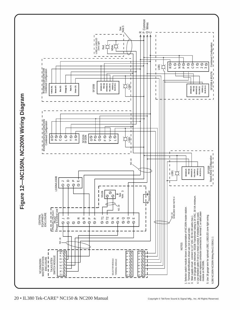
Fig
ure
12—
NC
150N
, NC
200N
Wir
ing
Dia
gra
m
SW
ITC
H M
OD
ULE
UN
JE
J D R R P T1 N Q E
P F VQ L
P X C 1 2 3
Red
Whi
te
R PC
omm
onW
ires
Q
See
SS
106
PK
151N
/ P
K15
1A /
See
Not
e3
TALK
/LIS
TEN
EN
CLO
SU
RE
MA
STE
R S
T ATI
ON
NC
150N
/200
N
EN
CLO
SU
RE
EQ
UIP
ME
NT
CE
NTR
AL
SE
LEC
TOR
MO
DU
LE
TER
MIN
AL
MO
DU
LE
LI38
1
N Q
J D P E
IR15
0N/1
51N
/152
N/1
53N
/155
N
LI38
1
NO
TES
1. S
elec
tor s
witc
h m
odul
e sh
own
is re
pres
enta
tive
of N
C15
0N m
aste
r sta
tion.
3. M
ain
supp
ly c
ircui
t: c
onne
ct to
117
VA
C, 6
0 H
z (4
0 w
atts
max
.).
U
se 1
8 ga
uge
wire
min
imum
. SS
106
Tran
sfor
mer
ratin
g is
24
VA
C, 3
0 V
A m
inim
um.
2 . T
erm
inal
iden
tific
atio
ns s
how
n ar
e no
t in
actu
al o
rde r
.
4. U
se s
hiel
ded
cabl
e if
not i
n a
met
al c
ondu
it. If
shi
elde
d ca
ble
is u
sed,
NO
. 22
NO
. 18
NO
. 18
LI38
2 or
LI3
82LE
D
SF1
51N
SF1
53N
G
T 2PS
F155
B
LI38
1
LI38
1
BR
OW
N (P
)
RE
D (Q
)
OR
AN
GE
(F)
YE
LLO
W (V
)
GR
EE
N (L
)
BLU
E (N
.U.)
BR
OW
N (P
)
RE
D (Q
)
OR
AN
GE
(F)
YE
LLO
W (V
)
GR
EE
N (L
)
BLU
E (N
.U.)
P L YC XR
R L N
BR
OW
N (P
)
RE
D (Q
)
OR
AN
GE
(F)
YE
LLO
W (V
)
GR
EE
N (L
)
BLU
E (N
.U.)
C
CD
PP
1N
O. 1
8
LL
XL
LX
LL
XL
LX
XXX
X
shie
ld w
ire re
plac
es c
ondu
ctor
con
nect
ed to
ter
min
al C
on
talk
/Lis
ten
mod
ule
on N
C15
0N.
5. U
se 1
8 ga
uge
wire
for o
ptio
nal L
I382
, LI3
82LE
D z
one
lIght
wiri
ng.
SH
IELD
ED
SE
E N
OTE
4
Cha
ssis
gro
und
Not
e 5
SF1
55B
SF1
55B
& IR
157N
LI15
0N/L
I150
B
Sta
nd A
lone
Con
figur
atio
nC
ombi
ned
Con
figur
atio
n
Com
bine
d C
onfig
urat
ion
Com
bine
d C
onfig
urat
ion
IR15
0B/1
51B
/152
B/1
55B
Pow
er &
Con
trol U
nit
PK
152
IL38
0 N
C15
0N N
C20
0N W
iring
Rev
11 0
3041
1 1
Zone
Lig
ht
IL380 Tek-CARE® NC150 & NC200 Manual • 21Copyright © TekTone Sound & Signal Mfg., Inc. All Rights Reserved.
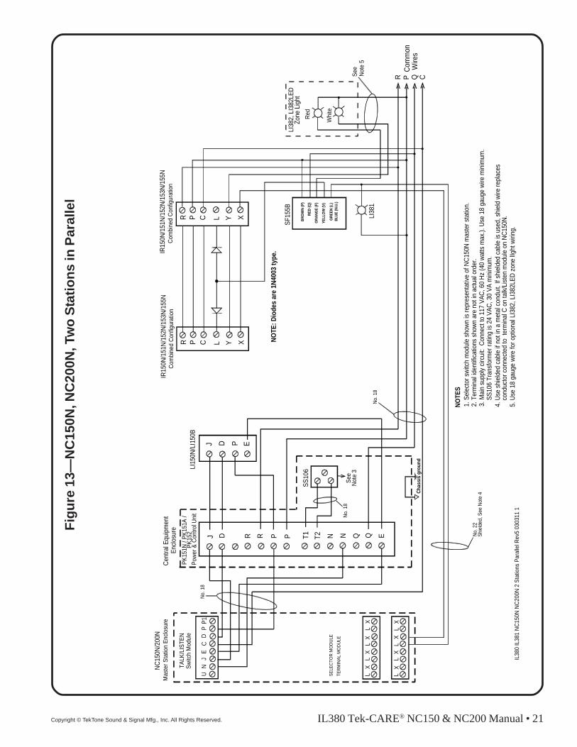
Fig
ure
13—
NC
150N
, NC
200N
, Tw
o S
tati
on
s in
Par
alle
l
Sw
itch
Mod
ule
UN
JE
J D R R P T1 Q E
Red
Wh i
te
RC
omm
onW
ires
QSee
SS
106
TALK
/LIS
TEN
Mas
ter S
tatio
n E
nclo
sure
NC
150N
/200
NC
entra
l Equ
ipm
ent
SE
LEC
TOR
MO
DU
LE
T ER
MIN
AL
MO
DU
LE
N Q
J D P E
IR15
0N/1
51N
/152
N/1
53N
/155
N
NO
TES
1. S
elec
tor s
witc
h m
odul
e sh
own
is re
pres
enta
tive
of N
C15
0N m
aste
r sta
tion.
3. M
ain
supp
ly c
ircui
t: C
onne
ct to
117
VA
C, 6
0 H
z (4
0 w
atts
max
.). U
se 1
8 ga
uge
wire
min
imum
.
SS
106
Tran
sfor
mer
ratin
g is
24
VA
C, 3
0 V
A m
inim
um.
2. T
erm
inal
iden
tific
atio
ns s
how
n ar
e no
t in
actu
al o
rder
.
4. U
se s
hiel
ded
cabl
e if
not i
n a
met
al c
ondu
it. If
shi
elde
d ca
ble
is u
sed,
shi
eld
wire
repl
aces
No.
22
No.
18
No.
18
LI38
2, L
I382
LED
T2PS
F155
B
LI38
1
BR
OW
N (P
)
RE
D (Q
)
OR
AN
GE
(F)
YE
LLO
W (V
)
GR
EE
N (L
)B
LUE
(N.U
.)
P YC XRP L YC XR
C
CD
PP
1N
o. 1
8
LL
XL
LX
LL
XL
LX
XXX
X
cond
ucto
r con
nect
ed to
ter
min
al C
on
talk
/Lis
ten
mod
ule
on N
C15
0N.
5. U
se 1
8 ga
uge
wire
for o
ptio
nal L
I382
, LI3
82LE
D z
one
lIght
wiri
ng.
Shi
elde
d, S
ee N
ote
4 Cha
ssis
gro
und
Not
e 5
LI15
0N/L
I150
B
Com
bine
d C
onfig
urat
ion
Com
bine
d C
onfig
urat
ion
IR15
0N/1
51N
/152
N/1
53N
/155
N
NO
TE: D
iode
s ar
e 1N
4003
type
.
IL38
0 IL
381
NC
150N
NC
200N
2 S
tatio
ns P
aral
lel R
ev5
0303
11 1
Enc
losu
re
See
Not
e 3
P
N
L
PK
151N
/ P
K15
1A /
Pow
er &
Con
trol U
nit
PK
152
Zone
Lig
ht
22 • IL380 Tek-CARE® NC150 & NC200 Manual Copyright © TekTone Sound & Signal Mfg., Inc. All Rights Reserved.
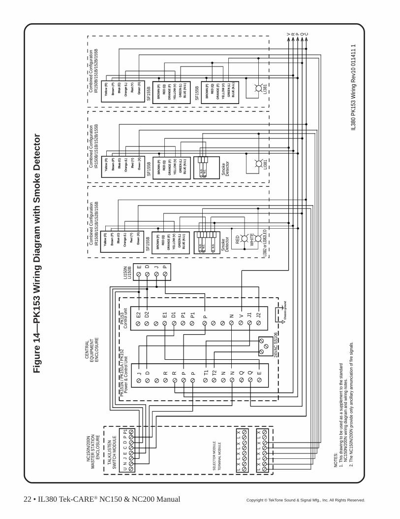
Fig
ure
14—
PK
153
Wir
ing
Dia
gra
m w
ith
Sm
oke
Det
ecto
r
EN
CLO
SU
RE
MA
STE
R S
TATI
ON
NC
150N
/200
N
EN
CLO
SU
RE
EQ
UIP
ME
NT
CE
NTR
AL
LI38
2 or
LI3
82LE
D
Com
bine
d C
onfig
urat
ion
J D R R P T 1 N Q E
24V
AC
SS
106
PK
151N
/ P
K15
1A /
PK
152
N QT2P
Pow
er &
Con
trol U
nit
E2 D2
E1
D1
P1
P N J1 J2
PK
153
P1
Con
trol u
nit
E J PD
LI15
0N
V
LI15
0B
V R P Q
N.O
.
N.O
.N
.C. W
HIT
E
RE
D
SF1
55B
LI38
1
BR
OW
N (P
)
RE
D (Q
)
OR
AN
GE
(F)
YE
LLO
W (V
)
GR
EE
N (L
)
BLU
E (N
.U.)
Com
bine
d C
onfig
urat
ion
N.O
.N
.C.
Sm
oke
Det
ecto
rS
mok
e D
etec
tor
SW
ITC
H M
OD
ULE
UN
JE
TALK
/LIS
TEN
SE
LEC
TOR
MO
DU
LE
T ER
MIN
AL
MO
DU
LE
CD
PP
1
LL
XL
LX
LL
XL
LX
XXX
X
IR15
0B/1
51B
/152
B/1
55B
C
NO
TES
:1.
Thi
s dr
awin
g to
be
used
as
a su
pple
men
t to
the
stan
dard
NC
150N
/200
N w
iring
dia
gram
and
wiri
ng n
otes
.2.
The
NC
150N
/200
N p
rovi
de o
nly
anci
llary
ann
unci
atio
n of
fire
sig
nals
.
Cha
ssis
gro
und
SF1
55B
LI38
1
BR
OW
N (P
)
RE
D (Q
)
OR
AN
GE
(F)
YE
LLO
W (V
)
GR
EE
N (L
)
BLU
E (N
.U.)
Com
bine
d C
onfig
urat
ion
IR15
0B/1
51B
/152
B/1
55B
SF1
55B
BR
OW
N (P
)
RE
D (Q
)
OR
AN
GE
(F)
YE
LLO
W (V
)
GR
EE
N (L
)
BLU
E (N
.U.)
IL38
0 P
K15
3 W
iring
Rev
10 0
1141
1 1
IR15
0B/1
51B
/152
B/1
55B
SF1
55B
BR
OW
N (P
)
RE
D (Q
)
OR
AN
GE
(F)
YE
LLO
W (V
)
GR
EE
N (L
)
BLU
E (N
.U.)

IL380 Tek-CARE® NC150 & NC200 Manual • 23Copyright © TekTone Sound & Signal Mfg., Inc. All Rights Reserved.
Fig
ure
15—
PK
153
Wir
ing
Dia
gra
m w
ith
SF
156B
Co
de
Sta
tio
n
EN
CLO
SU
RE
MA
STE
R S
TAT I
ON
NC
150N
/200
N
EN
CLO
SU
RE
EQ
UIP
ME
NT
CE
NTR
AL
LI38
2 or
LI3
82LE
D
Com
bine
d C
onfig
urat
ion
J D R R P T1 N Q E
2 4V
AC
SS
106
PK
151A
/ P
K15
2
N QT2P
Pow
er/C
ontro
l uni
t
E2 D2
E1
D1
P1
P N J1 J2
PK
153
P1
Con
trol u
nit
E J PD
LI15
0N
V
LI15
0B
V R P Q
WH
ITE
RE
D
SF1
55B
LI38
1
BR
OW
N (P
)
RE
D (Q
)
OR
AN
GE
(F)
YE
LLO
W (V
)
GR
EE
N (L
)
BLU
E (N
.U.)
Com
bine
d C
onfig
urat
ion
NO
TES
:
SW
ITC
H M
OD
ULE
UN
JE
TALK
/LIS
TEN
SE
LEC
TOR
MO
DU
LE
TER
MIN
AL
MO
DU
LE
CD
PP
1
LL
XL
LX
LL
XL
LX
XXX
X
IR15
0N/1
51N
/152
N/1
53N
/155
N
P F VQ LGP L YC XR
IR15
0B/1
51B
/152
B/1
55B
SF1
51N
SF1
53N
C
LI38
1
Sm
oke
dete
ctor
BR
OW
N (P
)
RE
D (Q
)
OR
AN
GE
(F)
YE
LLO
W (V
)
GR
EE
N (L
)
BLU
E (N
.U.)
SF1
56B
LI38
1
Sta
nd A
lone
Con
figur
atio
nS
tand
Alo
ne C
onfig
urat
ion
N.O
.N
.C.
SF1
56B
BR
OW
N (P
)
RE
D (Q
)
OR
AN
GE
(F)
YE
LLO
W (V
)
GR
EE
N (L
)
BLU
E (N
.U.)
P F VQ LG
SF1
56
1. T
his
draw
ing
to b
e us
ed a
s a
supp
lem
ent t
o th
e st
anda
rdN
C15
0N/2
00N
wiri
ng d
iagr
am a
nd w
iring
not
es.
2. T
he N
C15
0N/2
00N
pro
vide
onl
y an
cilla
ry a
nnun
ciat
ion
of fi
re s
igna
ls.
Cha
ssis
gro
und
IL38
0 P
K15
3 W
iring
2 R
ev8
0114
11 1

24 • IL380 Tek-CARE® NC150 & NC200 Manual Copyright © TekTone Sound & Signal Mfg., Inc. All Rights Reserved.
Fig
ure
16—
PK
151A
or
PK
152
to P
K80
0A In
terc
on
nec
tio
n
J D R R P T1 N Q E
24V
AC
SS
100
PK
800A
N QT2P
Pow
er s
uppl
yP
K15
1A /
PK
152
Con
trol u
nit
Fuse
Ass
y.
Mou
nt w
ithin
2 fe
et o
f eac
h ot
her.
Not
e:
T1 a
nd T
2 in
puts
whe
n in
terc
onne
ctin
g P
K80
0AS
econ
dary
Pow
er S
uppl
y!
Do
not c
onne
ct S
S10
6 Tr
ansf
orm
er to
PK
151A
/PK
152
Gro
und
Gro
und
Gro
und
Gro
und
24V
AC
24V
AC
24V
DC
24V
DC
24V
DC
5VD
C
5VD
C
5VD
C
To m
aste
r
To fi
eld
IL38
1 P
K15
1A P
K80
0A In
terc
onne
ctio
n R
ev5
0301
11
J D E P N R Q P
4A F
ast-B
low
INLI
NE
All
wiri
ng s
how
n is
18-
gaug
e.

IL380 Tek-CARE® NC150 & NC200 Manual • 25Copyright © TekTone Sound & Signal Mfg., Inc. All Rights Reserved.
Figure 17—SK151N Switch Board PCB Assembly

26 • IL380 Tek-CARE® NC150 & NC200 Manual Copyright © TekTone Sound & Signal Mfg., Inc. All Rights Reserved.
Bro
wn
Red
Ora
nge
Yel
low
Gre
en
Blu
e
on s
tatio
n
P Not
use
d
Q QLV
7 pi
n co
nnec
tor
Pur
ple
F NO
TE: B
oth
jum
pers
on
back
of s
tatio
nne
ed to
be
in u
p po
sitio
n!
DR
AW
ING
#: IL
380
IL38
1 S
F337
C W
IRIN
G R
EV
1 09
1603
1
EM
ER
GE
NC
Y
Not
e: B
oth
Ora
nge
& B
lue
wir
es a
re
conn
ecte
d to
"Q
" co
mm
on
and
mus
t be
conn
ecte
d to
geth
er.
Fig
ure
18—
SF
337C
Cro
ss R
efer
ence
Dia
gra
m

IL380 Tek-CARE® NC150 & NC200 Manual • 27Copyright © TekTone Sound & Signal Mfg., Inc. All Rights Reserved.
Bro
wn
Red
Ora
nge
Yel
low
Gre
en
Blu
e
on s
tatio
n
P Not
use
d
Q QLV
7 pi
n co
nnec
tor
Pur
ple
F
NO
TE: B
oth
jum
pers
on
back
of s
tatio
nne
ed to
be
in u
p po
sitio
n!
Bro
wn
Red
Ora
nge
Yel
low
Gre
en
Blu
e
on s
tatio
n
P Not
use
d
Q QLV
7 pi
n co
nnec
tor
Pur
ple
F
NO
TE: B
oth
jum
pers
on
back
of s
tatio
nne
ed to
be
in u
p po
sitio
n!
DR
AW
ING
#: IL
380
IL38
1 S
F339
WIR
ING
RE
V3
0916
03 1
Not
e: B
oth
Ora
nge
& B
lue
wir
es a
re
conn
ecte
d to
"Q
" co
mm
on
and
mus
t be
conn
ecte
d to
geth
er.
Fig
ure
19—
SF
339
Cro
ss R
efer
ence
Dia
gra
m

28 • IL380 Tek-CARE® NC150 & NC200 Manual Copyright © TekTone Sound & Signal Mfg., Inc. All Rights Reserved.
Figure 20—NC110N Hookup to NC150N, NC200N
MODULE
J D E E1
L L L L
N N P P
CONTROL
ENCLOSUREMASTER STATION
NC110N
SELECTOR MODULE
TERMINAL MODULE
D
J
E
N
PK151A / PK152
L
L
L
TOSELECTIVE LAMP
WIRE ONNC150N, NC200N
NC150N, NC200NTO
PK151A / PK152NC110NTO
N
P
IL381 NC110N NC150N NC200N Hookup Rev2 100110 1
#22
#18
#18
PK and NC150N/NC200Nmust not exceed 100'.
Total wire distance between