tekla structures 2016i - tekla user assistance · 1tekla structures administrator's release...
TRANSCRIPT

Tekla Structures 2016iTekla Structures 2016i administrator'srelease notes
September 2016
©2016 Trimble Solutions Corporation
Contents
1 Tekla Structures administrator's release notes.........................31.1 Administrator's release notes: General settings...........................................3
Administrator's release notes: Model templates in version update................................. 4Administrator's release notes: New gray colors for drawing hatches...............................8Administrator's release notes: Pattern lines...................................................................... 10Administrator's release notes: Custom grid labels............................................................14Administrator's release notes: Print drawings to PDF...................................................... 21Administrator's release notes: Reference model improvements for GA drawings....... 26Administrator's release notes: Applications & components catalog maintenance.......29Administrator's release notes: Enhanced objects.inp handling.......................................30Administrator's release notes: Small general items.......................................................... 30
1.2 Administrator's release notes: Steel settings..............................................35Administrator's release notes: Bent plates........................................................................ 35Administrator's release notes: Steel components.............................................................37
1.3 Administrator's release notes: Concrete settings.......................................39Administrator's release notes: Pours as management units........................................... 39Administrator's release notes: Integration of Automatic splicing tool to Meshbars and Mesh bars by area.................................................................................................41Administrator's release notes: Rebar coupler and anchor tools..................................... 43
2 Disclaimer.....................................................................................46
2
1 Tekla Structures administrator'srelease notes
Upgrade guide from Tekla Structures 2016 to Tekla Structures 2016i
Administrator's release notes are intended to provide advanced users withinstructions on how to apply the additional customizations available in a newTekla Structures version.
1.1 Administrator's release notes: General settingsGeneral customization settings apply to all user groups. Use these settingstogether with your own user group settings.
Administrator's release notes: Model templates in version update (page 3)
Administrator's release notes: New gray colors for drawing hatches (page 8)
Administrator's release notes: Pattern lines (page 10)
Administrator's release notes: Custom grid labels (page 14)
Administrator's release notes: Print drawings to PDF (page 21)
Administrator's release notes: Reference model improvements for GAdrawings (page 26)
Administrator's release notes: Applications & components catalogmaintenance (page 29)
Administrator's release notes: Enhanced objects.inp handling (page 30)
Administrator's release notes: Small general items (page 30)
Tekla Structures administrator's release notes 3 Administrator's release notes: General settings
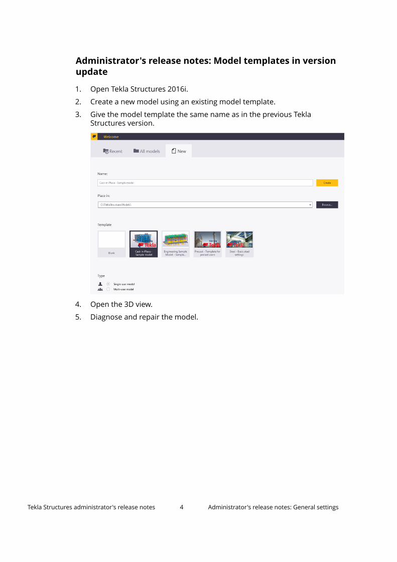
Administrator's release notes: Model templates in versionupdate
1. Open Tekla Structures 2016i.
2. Create a new model using an existing model template.
3. Give the model template the same name as in the previous TeklaStructures version.
4. Open the 3D view.
5. Diagnose and repair the model.
Tekla Structures administrator's release notes 4 Administrator's release notes: General settings
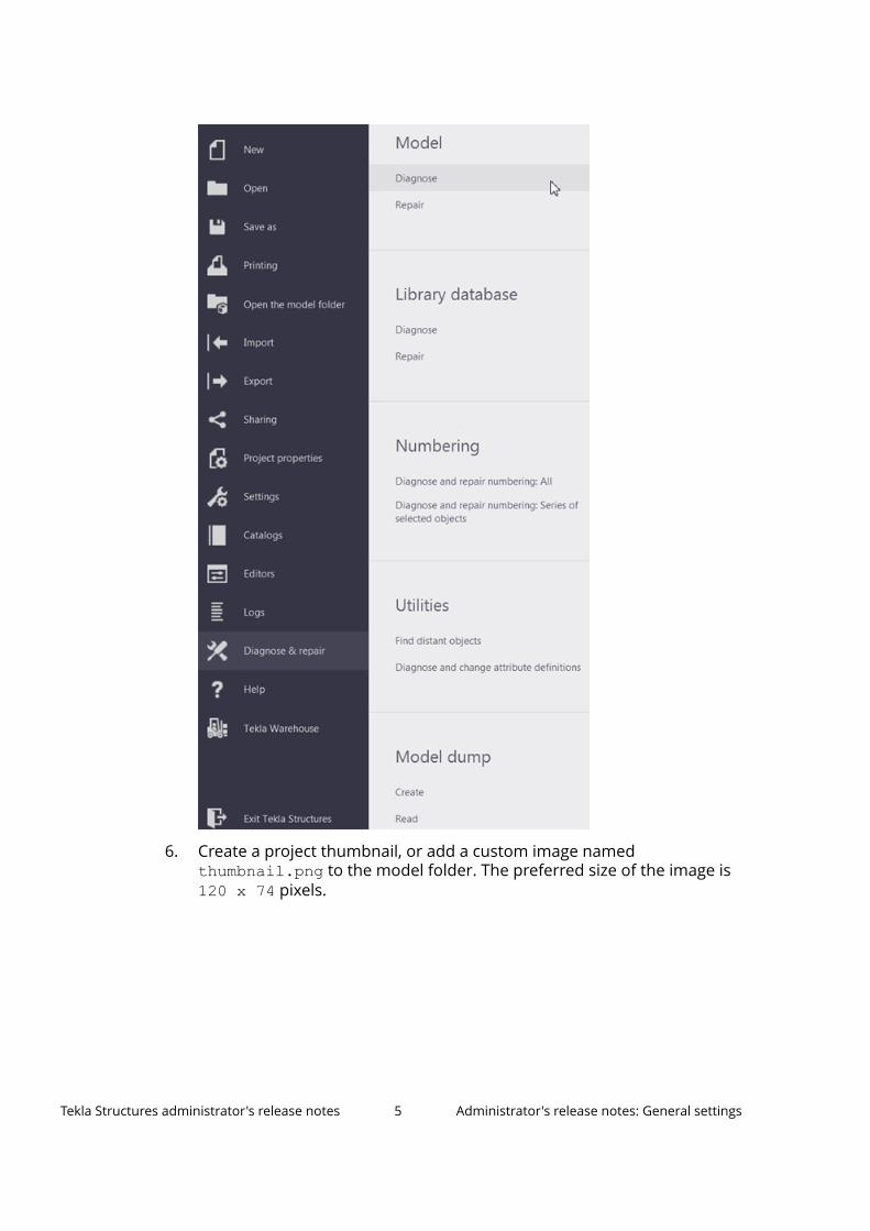
6. Create a project thumbnail, or add a custom image namedthumbnail.png to the model folder. The preferred size of the image is 120 x 74 pixels.
Tekla Structures administrator's release notes 5 Administrator's release notes: General settings
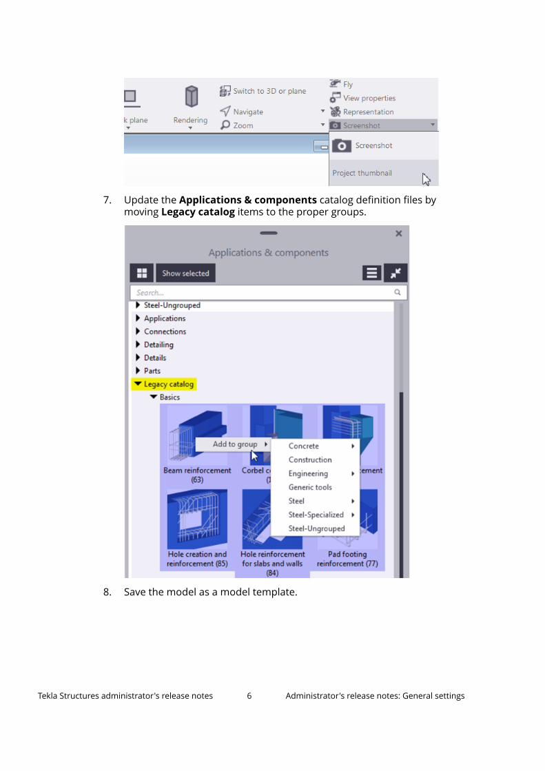
7. Update the Applications & components catalog definition files bymoving Legacy catalog items to the proper groups.
8. Save the model as a model template.
Tekla Structures administrator's release notes 6 Administrator's release notes: General settings
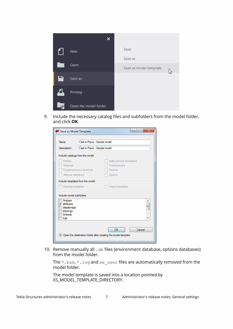
9. Include the necessary catalog files and subfolders from the model folder,and click OK.
10. Remove manually all .db files (environment database, options databases)from the model folder.
The *.bak, *.log and xs_user files are automatically removed from themodel folder.
The model template is saved into a location pointed byXS_MODEL_TEMPLATE_DIRECTORY.
Tekla Structures administrator's release notes 7 Administrator's release notes: General settings
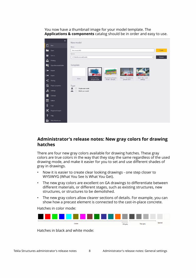
You now have a thumbnail image for your model template. TheApplications & components catalog should be in order and easy to use.
Administrator's release notes: New gray colors for drawinghatches
There are four new gray colors available for drawing hatches. These graycolors are true colors in the way that they stay the same regardless of the useddrawing mode, and make it easier for you to set and use different shades ofgray in drawings.
• Now it is easier to create clear looking drawings - one step closer toWYSIWYG (What You See Is What You Get).
• The new gray colors are excellent on GA drawings to differentiate betweendifferent materials, or different stages, such as existing structures, newstructures, or structures to be demolished.
• The new gray colors allow clearer sections of details. For example, you canshow how a precast element is connected to the cast-in-place concrete.
Hatches in color mode:
Hatches in black and white mode:
Tekla Structures administrator's release notes 8 Administrator's release notes: General settings
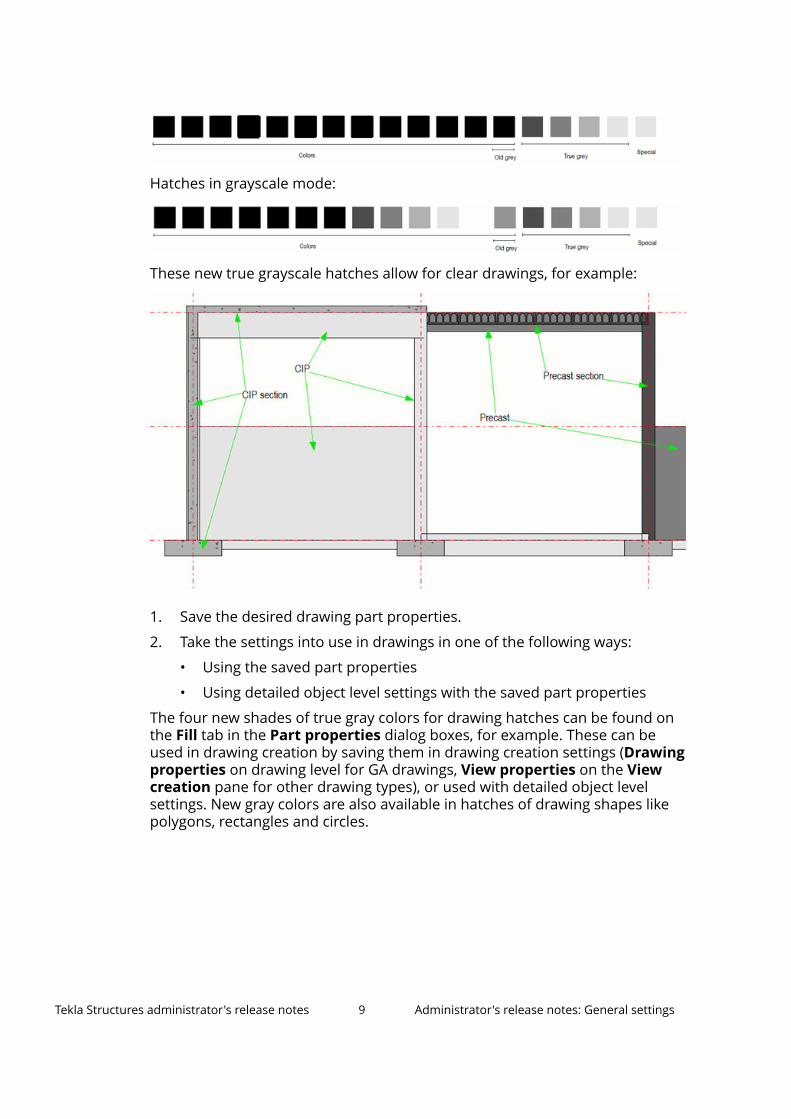
Hatches in grayscale mode:
These new true grayscale hatches allow for clear drawings, for example:
1. Save the desired drawing part properties.
2. Take the settings into use in drawings in one of the following ways:
• Using the saved part properties
• Using detailed object level settings with the saved part properties
The four new shades of true gray colors for drawing hatches can be found onthe Fill tab in the Part properties dialog boxes, for example. These can beused in drawing creation by saving them in drawing creation settings (Drawingproperties on drawing level for GA drawings, View properties on the Viewcreation pane for other drawing types), or used with detailed object levelsettings. New gray colors are also available in hatches of drawing shapes likepolygons, rectangles and circles.
Tekla Structures administrator's release notes 9 Administrator's release notes: General settings
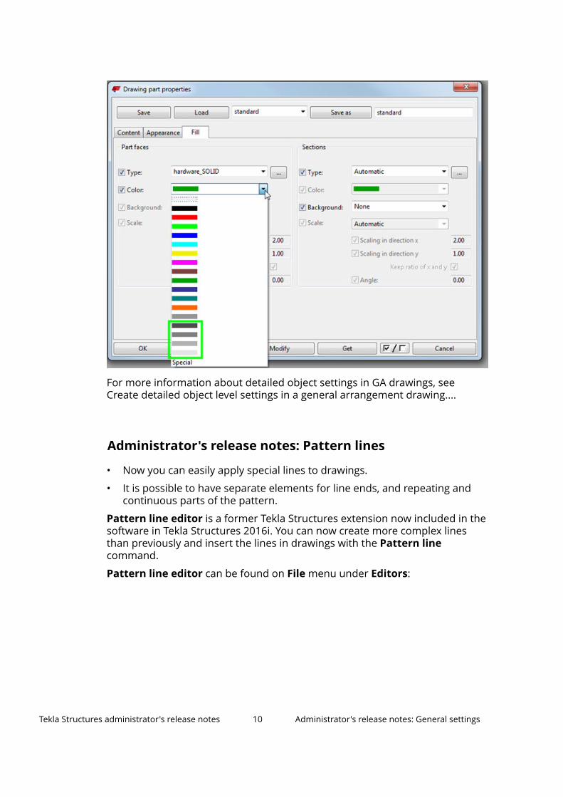
For more information about detailed object settings in GA drawings, seeCreate detailed object level settings in a general arrangement drawing....
Administrator's release notes: Pattern lines
• Now you can easily apply special lines to drawings.
• It is possible to have separate elements for line ends, and repeating andcontinuous parts of the pattern.
Pattern line editor is a former Tekla Structures extension now included in thesoftware in Tekla Structures 2016i. You can now create more complex linesthan previously and insert the lines in drawings with the Pattern linecommand.
Pattern line editor can be found on File menu under Editors:
Tekla Structures administrator's release notes 10 Administrator's release notes: General settings
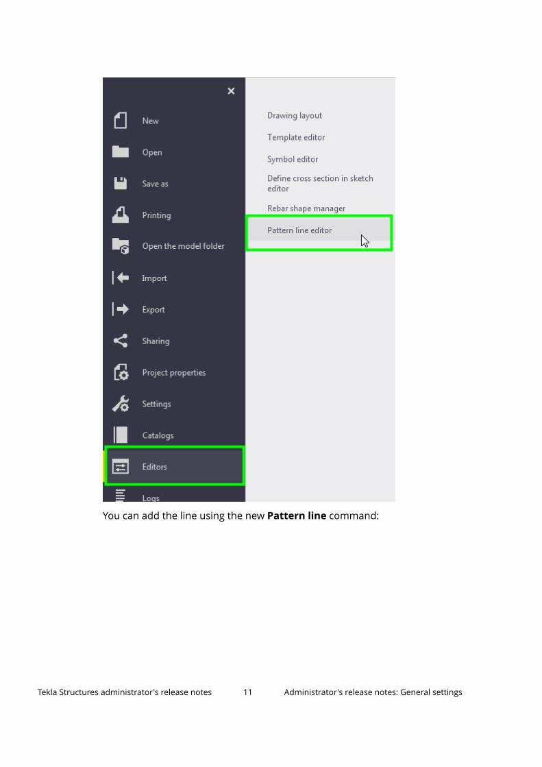
You can add the line using the new Pattern line command:
Tekla Structures administrator's release notes 11 Administrator's release notes: General settings
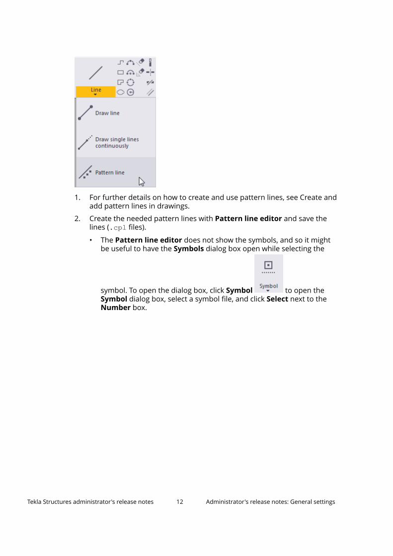
1. For further details on how to create and use pattern lines, see Create andadd pattern lines in drawings.
2. Create the needed pattern lines with Pattern line editor and save thelines (.cpl files).
• The Pattern line editor does not show the symbols, and so it mightbe useful to have the Symbols dialog box open while selecting the
symbol. To open the dialog box, click Symbol to open theSymbol dialog box, select a symbol file, and click Select next to theNumber box.
Tekla Structures administrator's release notes 12 Administrator's release notes: General settings
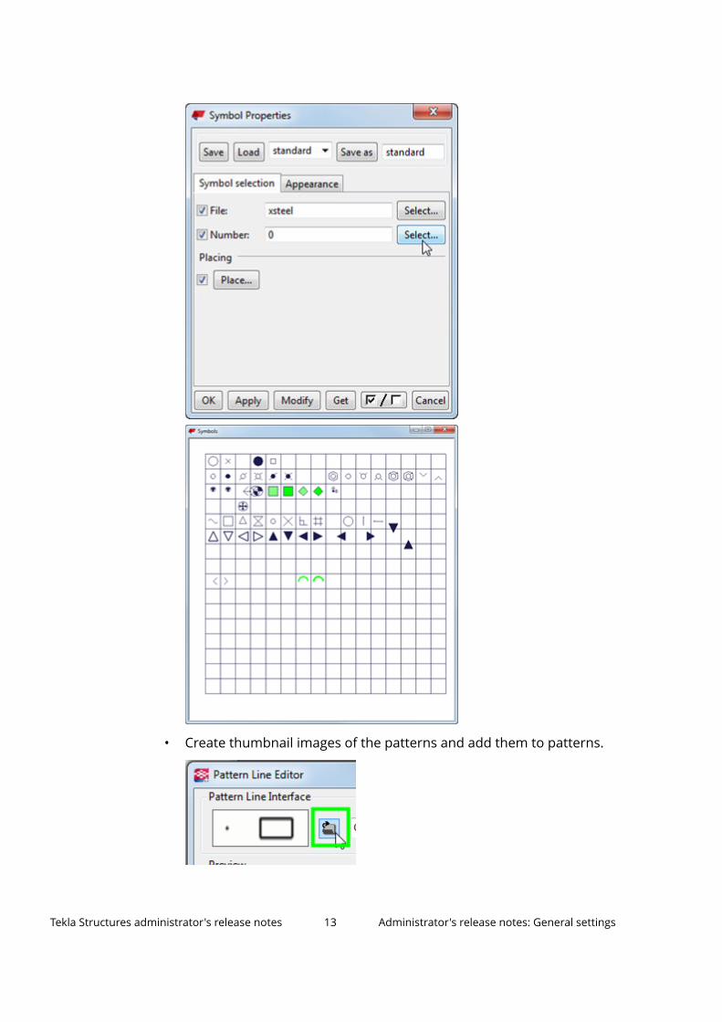
• Create thumbnail images of the patterns and add them to patterns.
Tekla Structures administrator's release notes 13 Administrator's release notes: General settings
3. Set suitable default settings for the pattern line(standard.PatternLine.Attributes.xml) .
The settings are applied when you add a pattern line.
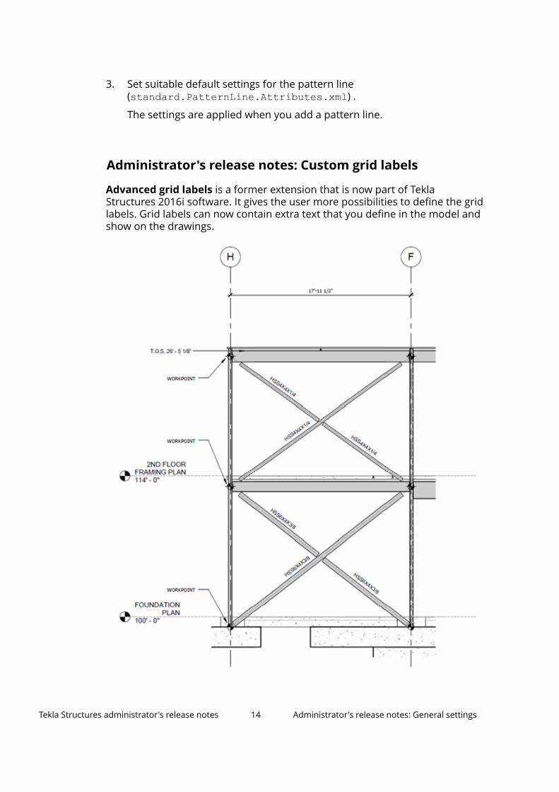
Administrator's release notes: Custom grid labels
Advanced grid labels is a former extension that is now part of TeklaStructures 2016i software. It gives the user more possibilities to define the gridlabels. Grid labels can now contain extra text that you define in the model andshow on the drawings.
Tekla Structures administrator's release notes 14 Administrator's release notes: General settings
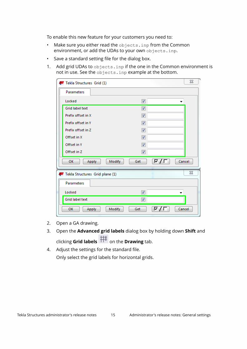
To enable this new feature for your customers you need to:
• Make sure you either read the objects.inp from the Commonenvironment, or add the UDAs to your own objects.inp.
• Save a standard setting file for the dialog box.
1. Add grid UDAs to objects.inp if the one in the Common environment isnot in use. See the objects.inp example at the bottom.
2. Open a GA drawing.
3. Open the Advanced grid labels dialog box by holding down Shift and
clicking Grid labels on the Drawing tab.
4. Adjust the settings for the standard file.
Only select the grid labels for horizontal grids.
Tekla Structures administrator's release notes 15 Administrator's release notes: General settings
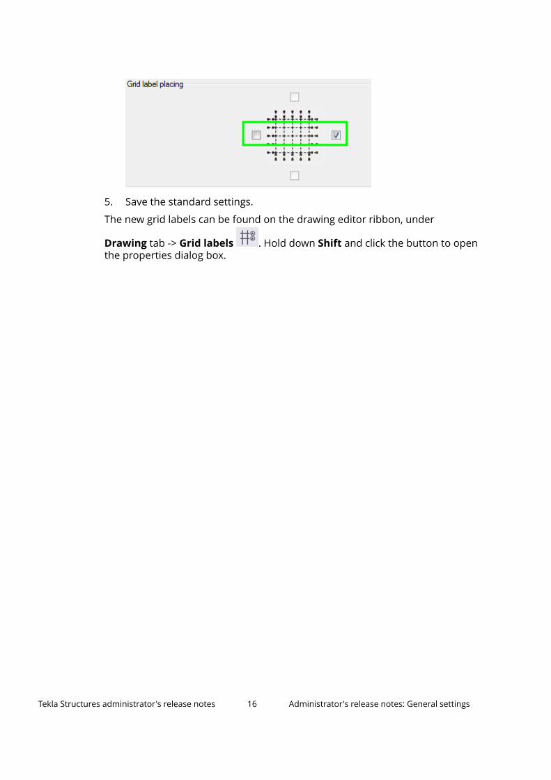
5. Save the standard settings.
The new grid labels can be found on the drawing editor ribbon, under
Drawing tab -> Grid labels . Hold down Shift and click the button to openthe properties dialog box.
Tekla Structures administrator's release notes 16 Administrator's release notes: General settings
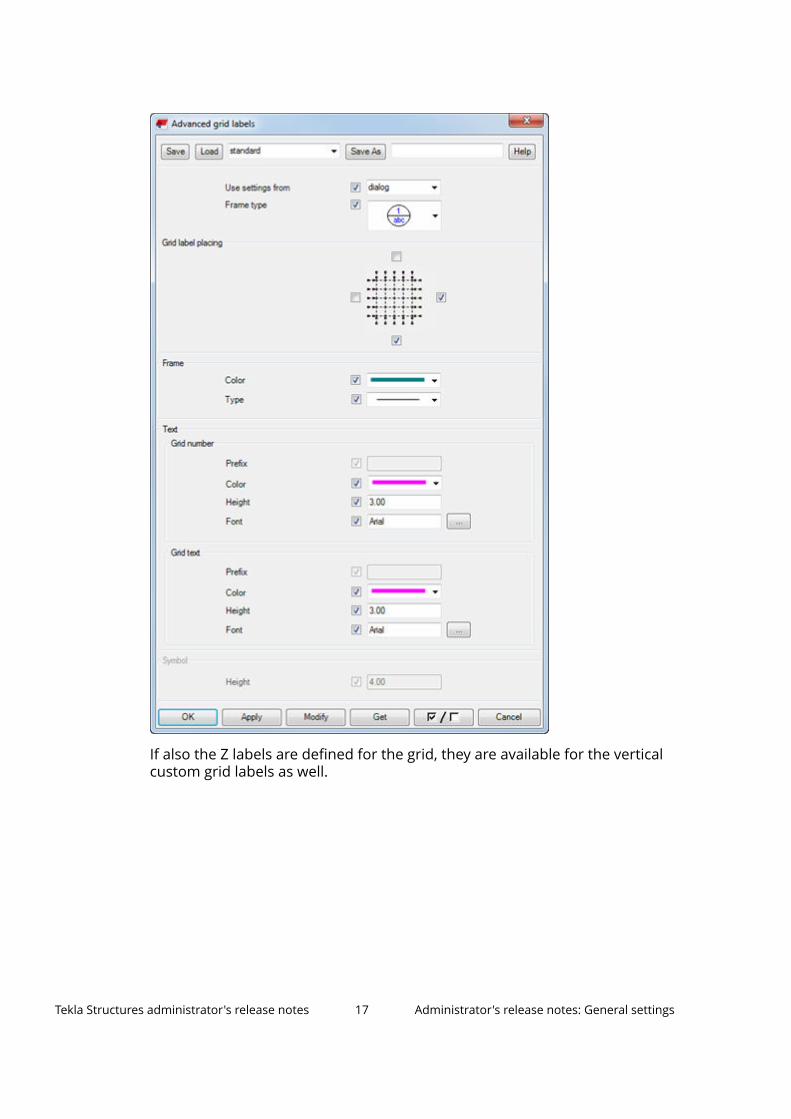
If also the Z labels are defined for the grid, they are available for the verticalcustom grid labels as well.
Tekla Structures administrator's release notes 17 Administrator's release notes: General settings
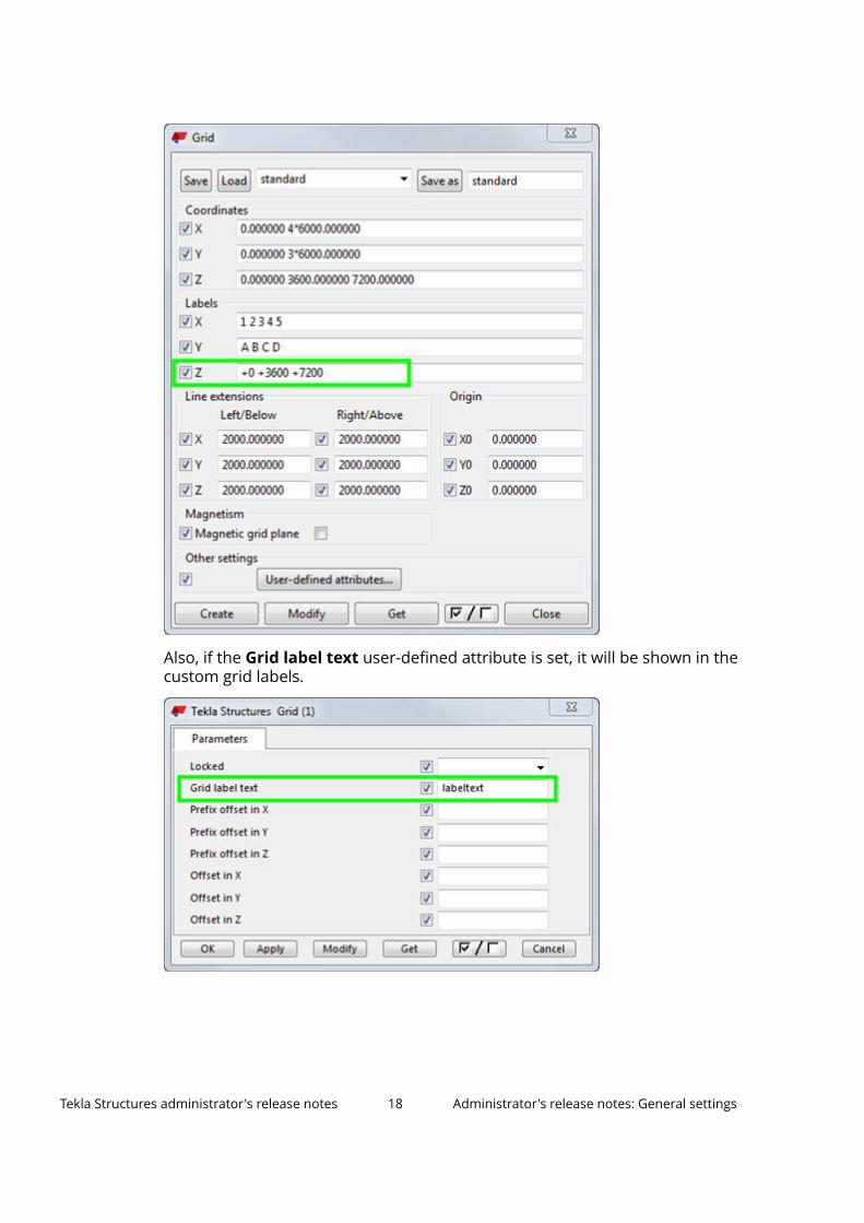
Also, if the Grid label text user-defined attribute is set, it will be shown in thecustom grid labels.
Tekla Structures administrator's release notes 18 Administrator's release notes: General settings
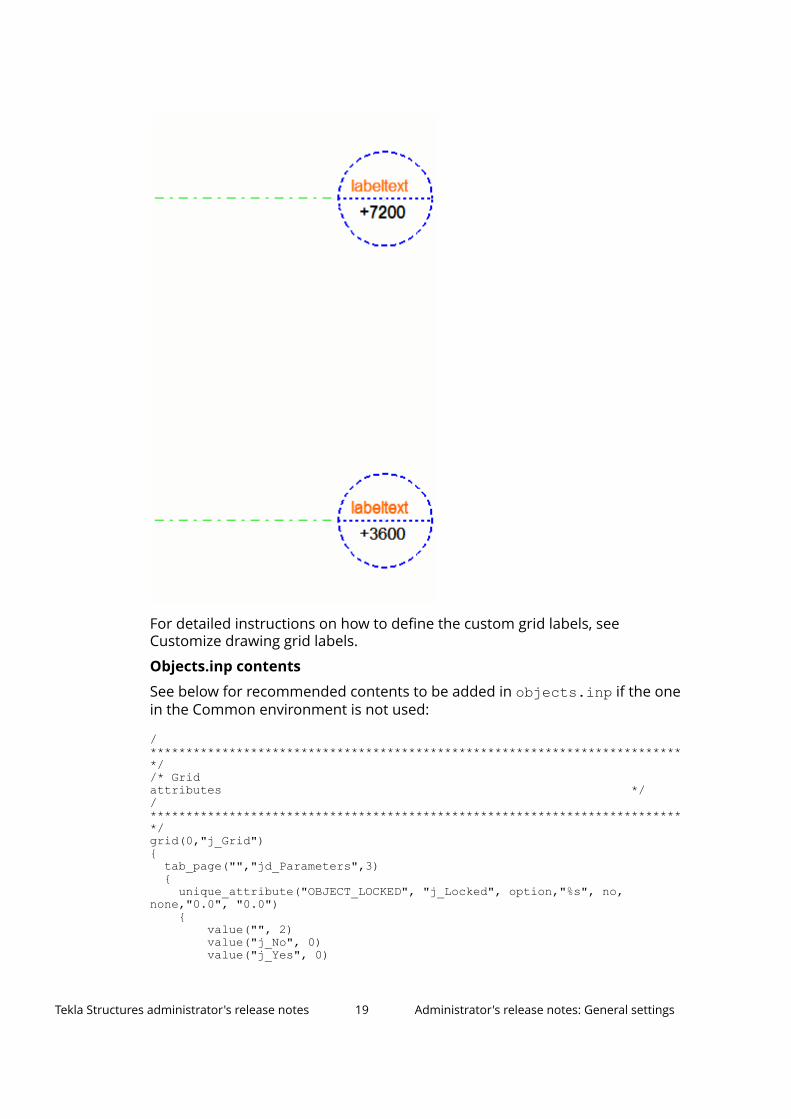
For detailed instructions on how to define the custom grid labels, seeCustomize drawing grid labels.
Objects.inp contents
See below for recommended contents to be added in objects.inp if the onein the Common environment is not used:
/***************************************************************************//* Gridattributes *//***************************************************************************/grid(0,"j_Grid"){
tab_page("","jd_Parameters",3){unique_attribute("OBJECT_LOCKED", "j_Locked", option,"%s", no,
none,"0.0", "0.0"){
value("", 2)value("j_No", 0)value("j_Yes", 0)
Tekla Structures administrator's release notes 19 Administrator's release notes: General settings
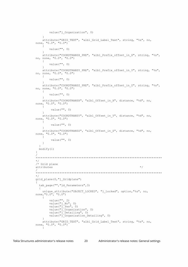
value("j_Organization", 0)}attribute("GRID_TEXT", "albl_Grid_Label_Text", string, "%s", no,
none, "0.0", "0.0"){
value("", 0)}attribute("COORDTRANSX_PRE", "albl_Prefix_offset_in_X", string, "%s",
no, none, "0.0", "0.0"){
value("", 0)}attribute("COORDTRANSY_PRE", "albl_Prefix_offset_in_Y", string, "%s",
no, none, "0.0", "0.0"){
value("", 0)}attribute("COORDTRANSZ_PRE", "albl_Prefix_offset_in_Z", string, "%s",
no, none, "0.0", "0.0"){
value("", 0)}attribute("COORDTRANSX", "albl_Offset_in_X", distance, "%d", no,
none, "0.0", "0.0"){
value("", 0)}attribute("COORDTRANSY", "albl_Offset_in_Y", distance, "%d", no,
none, "0.0", "0.0"){
value("", 0)}attribute("COORDTRANSZ", "albl_Offset_in_Z", distance, "%d", no,
none, "0.0", "0.0"){
value("", 0)}
}modify(1)
}/***************************************************************************//* Grid planeattributes *//***************************************************************************/grid_plane(0,"j_Gridplane"){
tab_page("","jd_Parameters",3){
unique_attribute("OBJECT_LOCKED", "j_Locked", option,"%s", no,none,"0.0", "0.0")
{value("", 2)value("j_No", 0)value("j_Yes", 0)value("j_Organization", 0)value("j_Detailing", 0)value("j_Organization_Detailing", 0)
}attribute("GRID_TEXT", "albl_Grid_Label_Text", string, "%s", no,
none, "0.0", "0.0"){
Tekla Structures administrator's release notes 20 Administrator's release notes: General settings
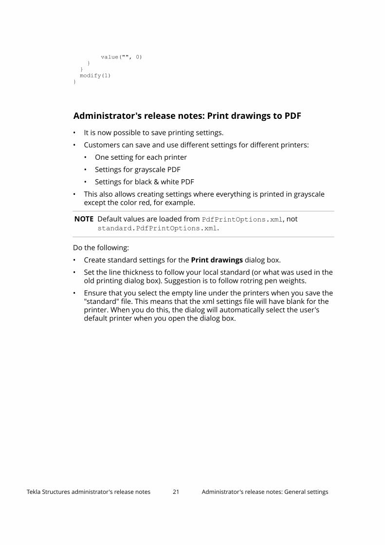
value("", 0) } } modify(1)}
Administrator's release notes: Print drawings to PDF
• It is now possible to save printing settings.
• Customers can save and use different settings for different printers:
• One setting for each printer
• Settings for grayscale PDF
• Settings for black & white PDF
• This also allows creating settings where everything is printed in grayscaleexcept the color red, for example.
NOTE Default values are loaded from PdfPrintOptions.xml, notstandard.PdfPrintOptions.xml.
Do the following:
• Create standard settings for the Print drawings dialog box.
• Set the line thickness to follow your local standard (or what was used in theold printing dialog box). Suggestion is to follow rotring pen weights.
• Ensure that you select the empty line under the printers when you save the"standard" file. This means that the xml settings file will have blank for theprinter. When you do this, the dialog will automatically select the user'sdefault printer when you open the dialog box.
Tekla Structures administrator's release notes 21 Administrator's release notes: General settings
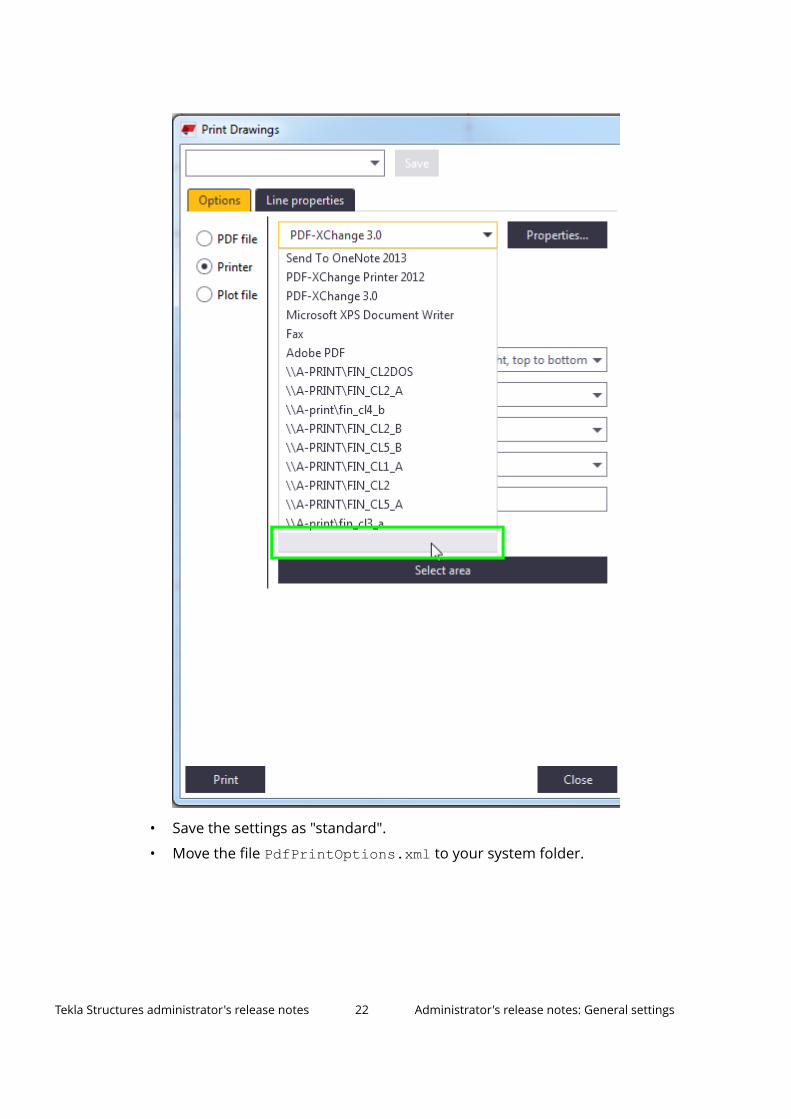
• Save the settings as "standard".
• Move the file PdfPrintOptions.xml to your system folder.
Tekla Structures administrator's release notes 22 Administrator's release notes: General settings
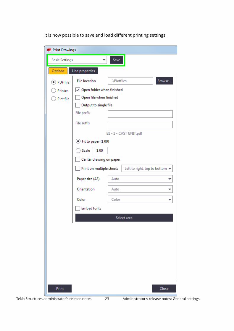
It is now possible to save and load different printing settings.
Tekla Structures administrator's release notes 23 Administrator's release notes: General settings

There are new gray colors that can only be used for printing hatches.
Tekla Structures administrator's release notes 24 Administrator's release notes: General settings
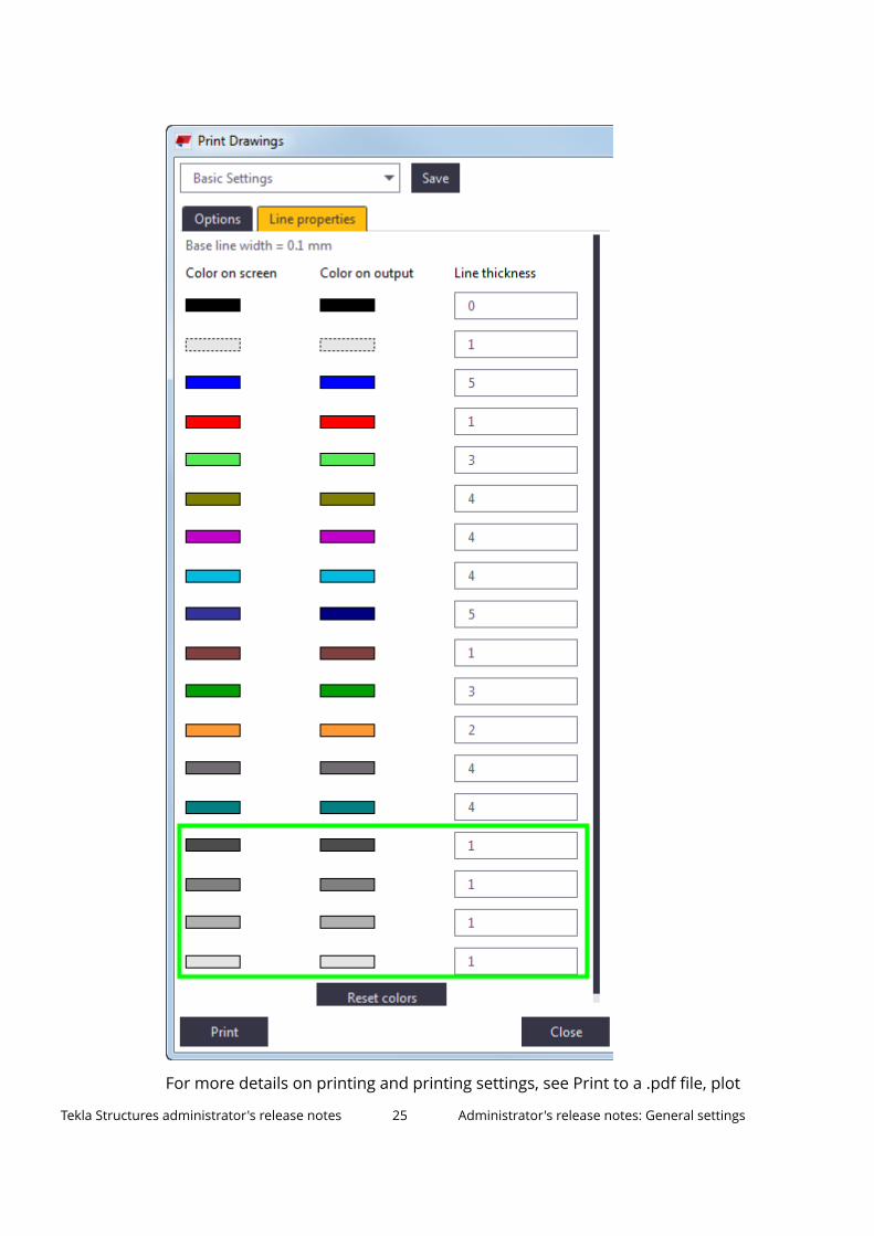
For more details on printing and printing settings, see Print to a .pdf file, plot
Tekla Structures administrator's release notes 25 Administrator's release notes: General settings
file (.plt) or printer and Printing settings and search order.
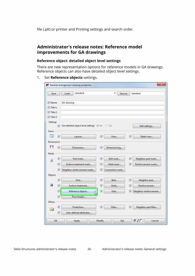
Administrator's release notes: Reference modelimprovements for GA drawings
Reference object: detailed object level settings
There are new representation options for reference models in GA drawings.Reference objects can also have detailed object level settings.
1. Set Reference objects settings.
Tekla Structures administrator's release notes 26 Administrator's release notes: General settings
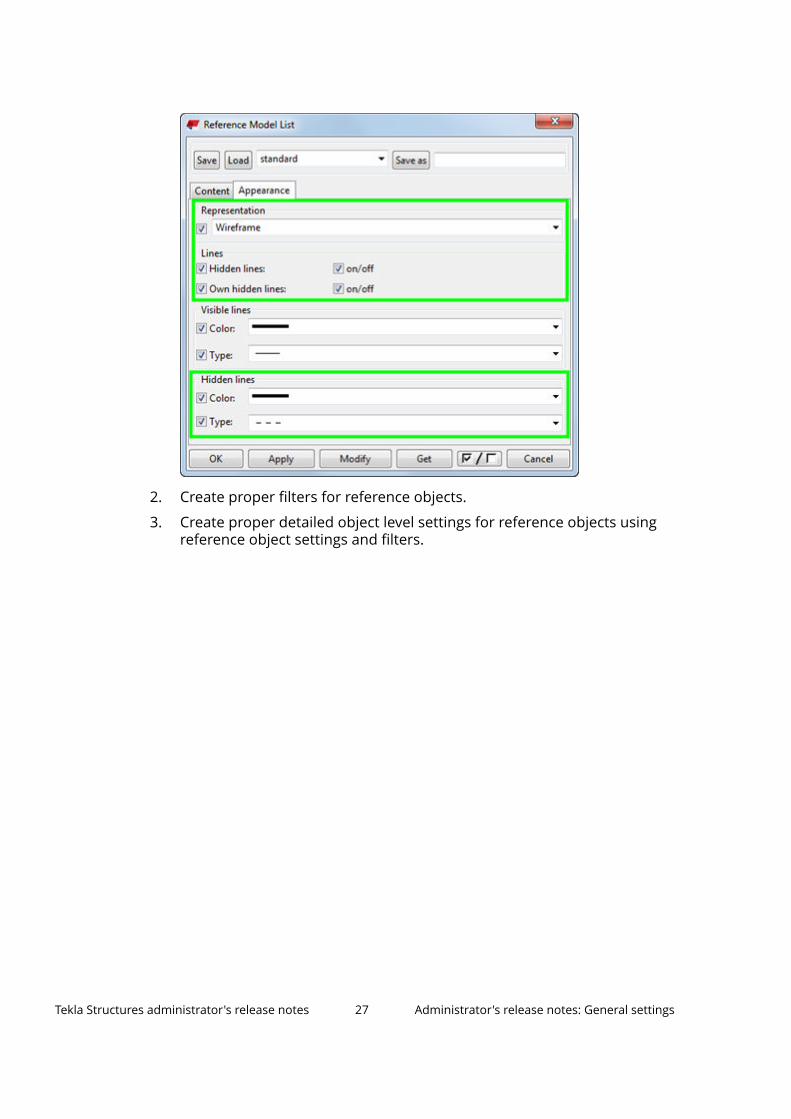
2. Create proper filters for reference objects.
3. Create proper detailed object level settings for reference objects usingreference object settings and filters.
Tekla Structures administrator's release notes 27 Administrator's release notes: General settings
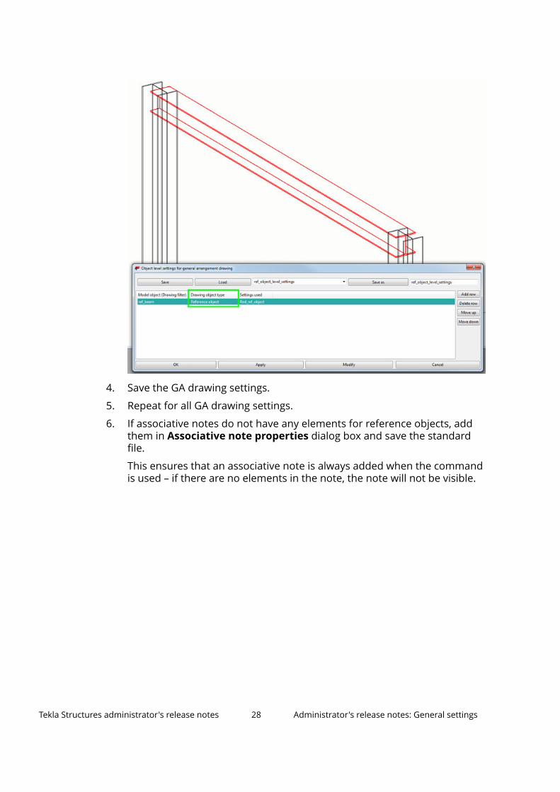
4. Save the GA drawing settings.
5. Repeat for all GA drawing settings.
6. If associative notes do not have any elements for reference objects, addthem in Associative note properties dialog box and save the standardfile.
This ensures that an associative note is always added when the commandis used – if there are no elements in the note, the note will not be visible.
Tekla Structures administrator's release notes 28 Administrator's release notes: General settings
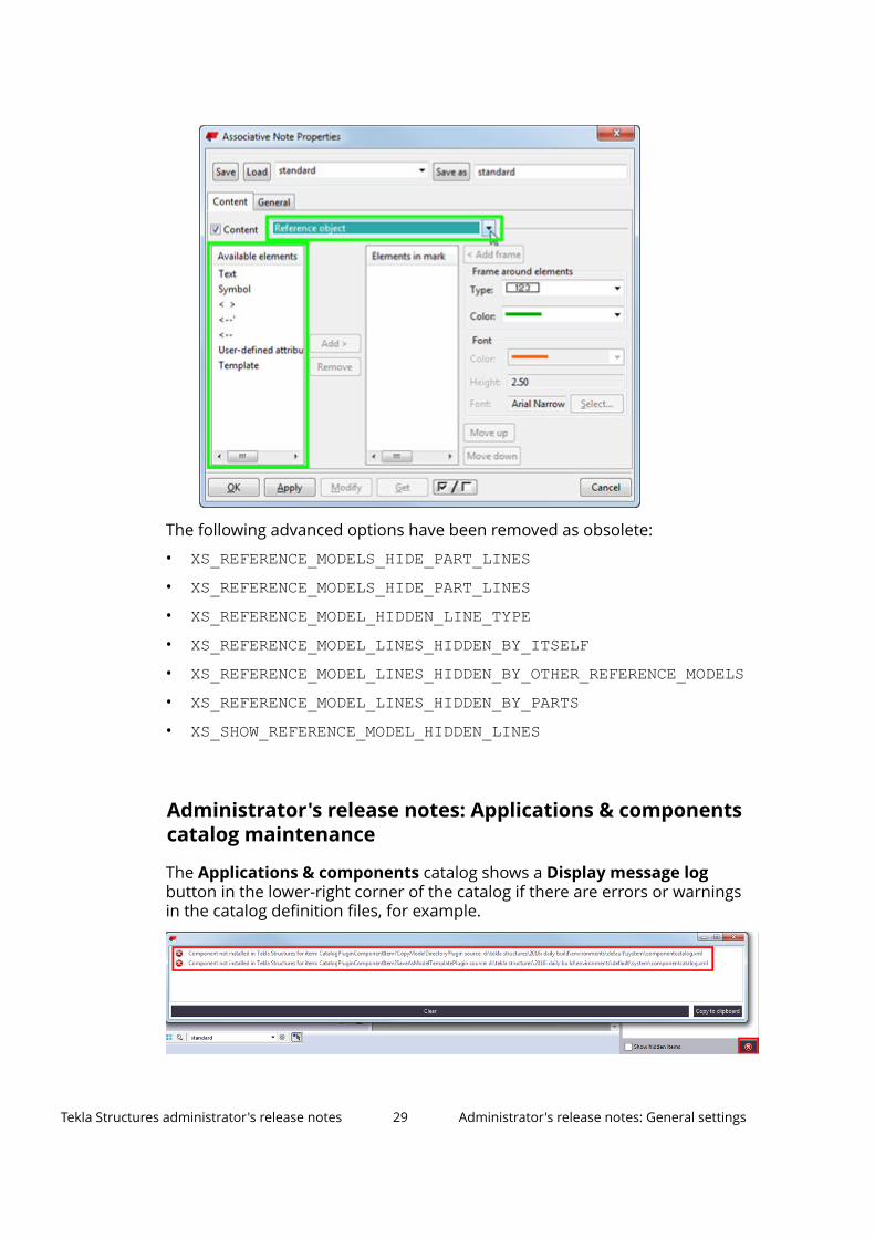
The following advanced options have been removed as obsolete:
• XS_REFERENCE_MODELS_HIDE_PART_LINES• XS_REFERENCE_MODELS_HIDE_PART_LINES• XS_REFERENCE_MODEL_HIDDEN_LINE_TYPE• XS_REFERENCE_MODEL_LINES_HIDDEN_BY_ITSELF• XS_REFERENCE_MODEL_LINES_HIDDEN_BY_OTHER_REFERENCE_MODELS• XS_REFERENCE_MODEL_LINES_HIDDEN_BY_PARTS• XS_SHOW_REFERENCE_MODEL_HIDDEN_LINES
Administrator's release notes: Applications & componentscatalog maintenance
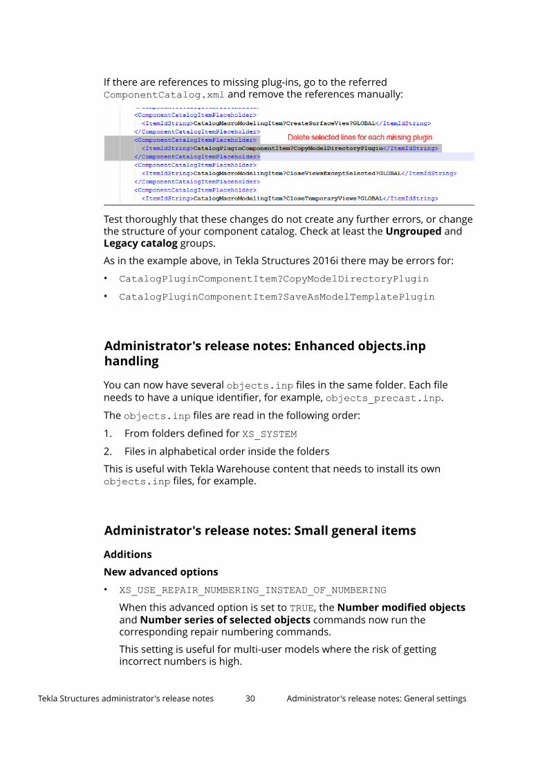
The Applications & components catalog shows a Display message logbutton in the lower-right corner of the catalog if there are errors or warningsin the catalog definition files, for example.
Tekla Structures administrator's release notes 29 Administrator's release notes: General settings
If there are references to missing plug-ins, go to the referredComponentCatalog.xml and remove the references manually:
Test thoroughly that these changes do not create any further errors, or changethe structure of your component catalog. Check at least the Ungrouped andLegacy catalog groups.
As in the example above, in Tekla Structures 2016i there may be errors for:
• CatalogPluginComponentItem?CopyModelDirectoryPlugin• CatalogPluginComponentItem?SaveAsModelTemplatePlugin
Administrator's release notes: Enhanced objects.inphandling
You can now have several objects.inp files in the same folder. Each fileneeds to have a unique identifier, for example, objects_precast.inp.
The objects.inp files are read in the following order:
1. From folders defined for XS_SYSTEM2. Files in alphabetical order inside the folders
This is useful with Tekla Warehouse content that needs to install its ownobjects.inp files, for example.
Administrator's release notes: Small general items
Additions
New advanced options
• XS_USE_REPAIR_NUMBERING_INSTEAD_OF_NUMBERINGWhen this advanced option is set to TRUE, the Number modified objectsand Number series of selected objects commands now run thecorresponding repair numbering commands.
This setting is useful for multi-user models where the risk of gettingincorrect numbers is high.
Tekla Structures administrator's release notes 30 Administrator's release notes: General settings
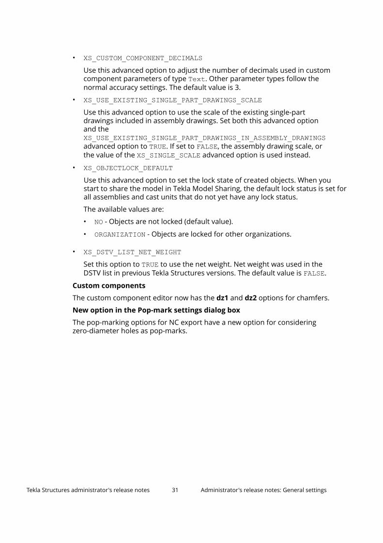
• XS_CUSTOM_COMPONENT_DECIMALSUse this advanced option to adjust the number of decimals used in customcomponent parameters of type Text. Other parameter types follow thenormal accuracy settings. The default value is 3.
• XS_USE_EXISTING_SINGLE_PART_DRAWINGS_SCALEUse this advanced option to use the scale of the existing single-partdrawings included in assembly drawings. Set both this advanced optionand theXS_USE_EXISTING_SINGLE_PART_DRAWINGS_IN_ASSEMBLY_DRAWINGSadvanced option to TRUE. If set to FALSE, the assembly drawing scale, orthe value of the XS_SINGLE_SCALE advanced option is used instead.
• XS_OBJECTLOCK_DEFAULTUse this advanced option to set the lock state of created objects. When you start to share the model in Tekla Model Sharing, the default lock status is set for all assemblies and cast units that do not yet have any lock status.
The available values are:
• NO - Objects are not locked (default value).
• ORGANIZATION - Objects are locked for other organizations.
• XS_DSTV_LIST_NET_WEIGHTSet this option to TRUE to use the net weight. Net weight was used in theDSTV list in previous Tekla Structures versions. The default value is FALSE.
Custom components
The custom component editor now has the dz1 and dz2 options for chamfers.
New option in the Pop-mark settings dialog box
The pop-marking options for NC export have a new option for consideringzero-diameter holes as pop-marks.
Tekla Structures administrator's release notes 31 Administrator's release notes: General settings
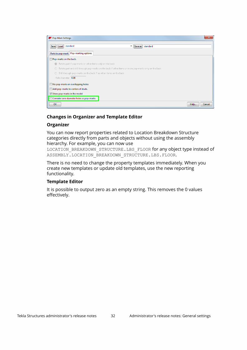
Changes in Organizer and Template Editor
Organizer
You can now report properties related to Location Breakdown Structurecategories directly from parts and objects without using the assemblyhierarchy. For example, you can now use LOCATION_BREAKDOWN_STRUCTURE.LBS_FLOOR for any object type instead of ASSEMBLY.LOCATION_BREAKDOWN_STRUCTURE.LBS.FLOOR.
There is no need to change the property templates immediately. When youcreate new templates or update old templates, use the new reportingfunctionality.
Template Editor
It is possible to output zero as an empty string. This removes the 0 valueseffectively.
Tekla Structures administrator's release notes 32 Administrator's release notes: General settings
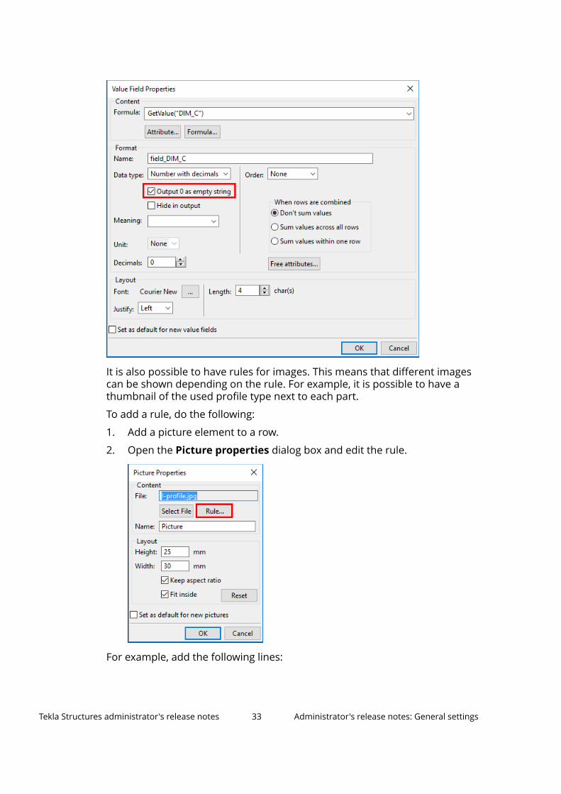
It is also possible to have rules for images. This means that different imagescan be shown depending on the rule. For example, it is possible to have athumbnail of the used profile type next to each part.
To add a rule, do the following:
1. Add a picture element to a row.
2. Open the Picture properties dialog box and edit the rule.
For example, add the following lines:
Tekla Structures administrator's release notes 33 Administrator's release notes: General settings
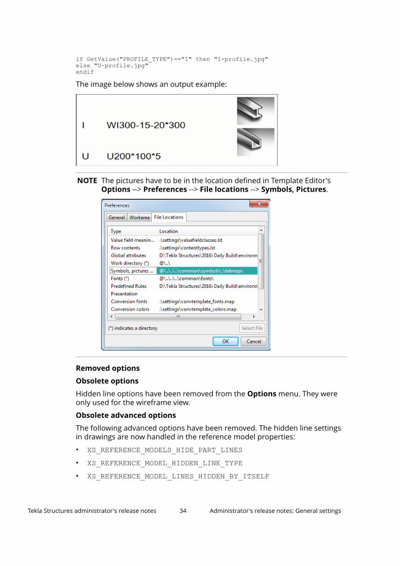
if GetValue("PROFILE_TYPE")=="I" then "I-profile.jpg"else "U-profile.jpg"endif
The image below shows an output example:
NOTE The pictures have to be in the location defined in Template Editor'sOptions --> Preferences --> File locations --> Symbols, Pictures.
Removed options
Obsolete options
Hidden line options have been removed from the Options menu. They wereonly used for the wireframe view.
Obsolete advanced options
The following advanced options have been removed. The hidden line settingsin drawings are now handled in the reference model properties:
• XS_REFERENCE_MODELS_HIDE_PART_LINES• XS_REFERENCE_MODEL_HIDDEN_LINE_TYPE• XS_REFERENCE_MODEL_LINES_HIDDEN_BY_ITSELF
Tekla Structures administrator's release notes 34 Administrator's release notes: General settings
• XS_REFERENCE_MODEL_LINES_HIDDEN_BY_OTHER_REFERENCE_MODELS• XS_REFERENCE_MODEL_LINES_HIDDEN_BY_PARTS• XS_SHOW_REFERENCE_MODEL_HIDDEN_LINES
1.2 Administrator's release notes: Steel settingsThe following customization settings only apply to the steel user group.
Administrator's release notes: Bent plates (page 35)
Administrator's release notes: Steel components (page 37)
Administrator's release notes: Bent plates
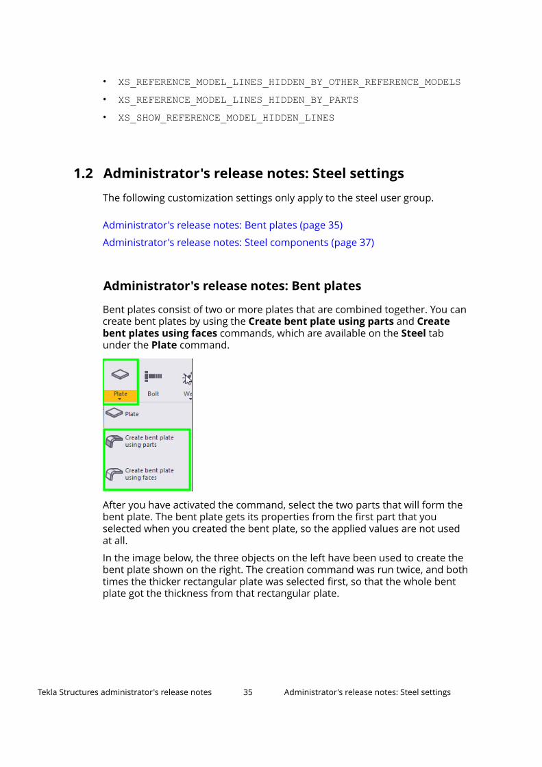
Bent plates consist of two or more plates that are combined together. You cancreate bent plates by using the Create bent plate using parts and Createbent plates using faces commands, which are available on the Steel tabunder the Plate command.
After you have activated the command, select the two parts that will form thebent plate. The bent plate gets its properties from the first part that youselected when you created the bent plate, so the applied values are not usedat all.
In the image below, the three objects on the left have been used to create thebent plate shown on the right. The creation command was run twice, and bothtimes the thicker rectangular plate was selected first, so that the whole bentplate got the thickness from that rectangular plate.
Tekla Structures administrator's release notes 35 Administrator's release notes: Steel settings
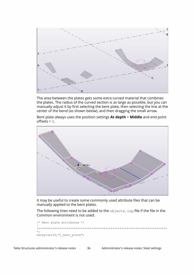
The area between the plates gets some extra curved material that combinesthe plates. The radius of the curved section is as large as possible, but you canmanually adjust it by first selecting the bent plate, then selecting the line at thecenter of the bend (as shown below), and then dragging the small arrow.
Bent plate always uses the position settings At depth = Middle and end pointoffsets = 0.
It may be useful to create some commonly used attribute files that can bemanually applied to the bent plates.
The following lines need to be added to the objects.inp file if the file in theCommon environment is not used:
/* Bent plate attributes *//***************************************************************************/bentplate(0,"j_bent_plate")
Tekla Structures administrator's release notes 36 Administrator's release notes: Steel settings
{ tab_page("Parameters","jd_Parameters",4) tab_page("IFCparameters","jd_IFC_export",9) modify(1)}/***************************************************************************/
Administrator's release notes: Steel components
The following components have user interface changes:
• Tensioner brace (13)
• Joist seat (58)
• Column splice (132)
• Joist column, type 1 (161)
• Joist column, type 2 (163)
• Joist to beam and col. (164)
• Joist bearing plate (1067)
The following components contain fixes:
• Double plate (50)
• Wraparound gusset (58)
• Wraparound gusset cross (60)
• Gusseted cross (62)
• Corner wrapped gusset (63)
• Splice connection (77)
• Squeezed tube bolted (102)
• Stub connection (119)
• Bolted moment connection (134)
• End plate (144)
• Base plate (1004)
• Stairs (S71)
• Wooden steps pan (S72)
• Z pan (S74)
Other changes
Base plate (1004)
You can now use custom components as anchor rods in Base plate (1004).
Tekla Structures administrator's release notes 37 Administrator's release notes: Steel settings
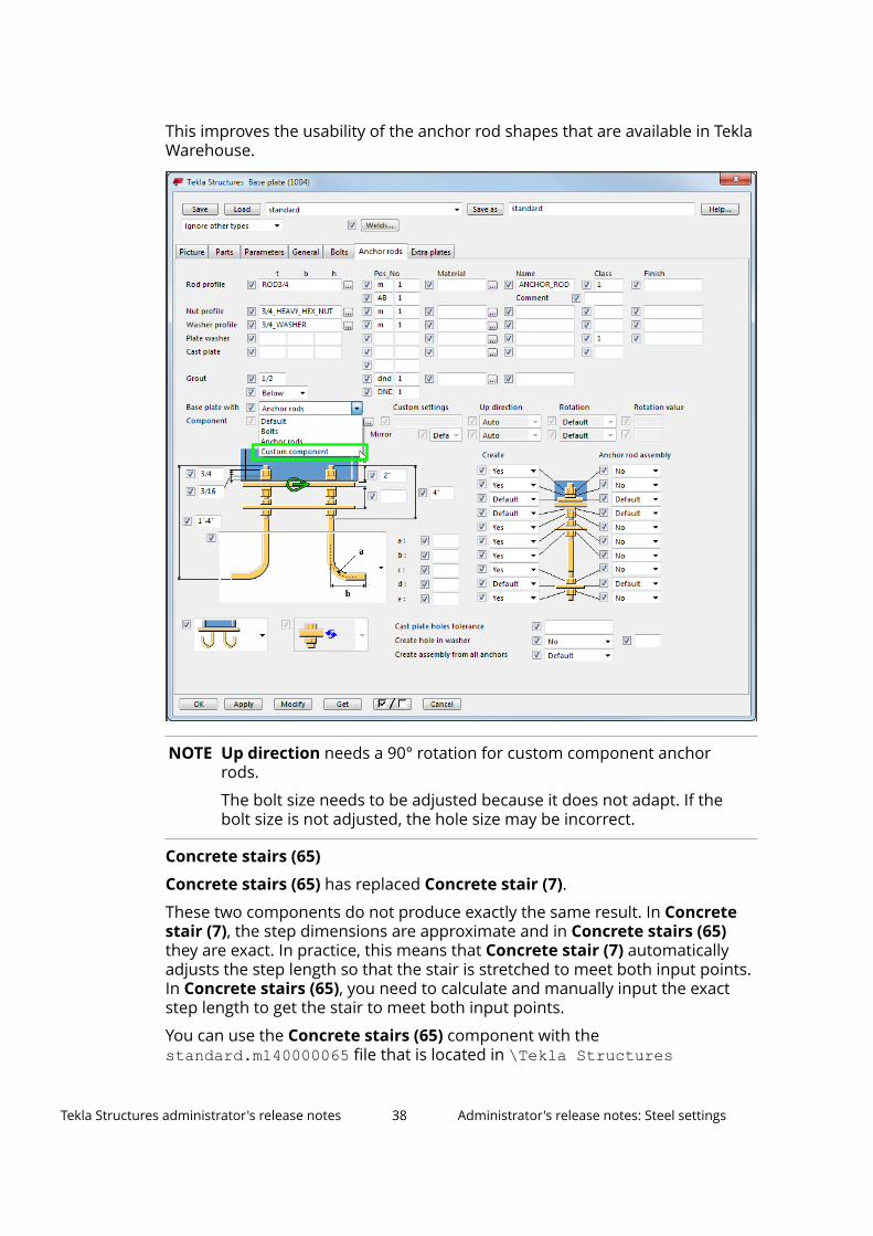
This improves the usability of the anchor rod shapes that are available in TeklaWarehouse.
NOTE Up direction needs a 90° rotation for custom component anchorrods.
The bolt size needs to be adjusted because it does not adapt. If thebolt size is not adjusted, the hole size may be incorrect.
Concrete stairs (65)
Concrete stairs (65) has replaced Concrete stair (7).
These two components do not produce exactly the same result. In Concretestair (7), the step dimensions are approximate and in Concrete stairs (65)they are exact. In practice, this means that Concrete stair (7) automaticallyadjusts the step length so that the stair is stretched to meet both input points.In Concrete stairs (65), you need to calculate and manually input the exactstep length to get the stair to meet both input points.
You can use the Concrete stairs (65) component with thestandard.m140000065 file that is located in \Tekla Structures
Tekla Structures administrator's release notes 38 Administrator's release notes: Steel settings
\<version>\Environments\common\system\Steel to create simpleconcrete stairs for reference purposes, instead of the Concrete stair (7)component.
1.3 Administrator's release notes: Concrete settingsThe following customization settings only apply to the concrete user group.
Administrator's release notes: Pours as management units (page 39)
Administrator's release notes: Integration of Automatic splicing tool to Meshbars and Mesh bars by area (page 40)
Administrator's release notes: Rebar coupler and anchor tools (page 42)
Administrator's release notes: Pours as management units
You can now create pour units from pour objects and other model objects. Apour unit is a management unit that consists of a pour object and relatedreinforcement, embeds, and other objects that need to be in place beforeconcrete can be poured on the building site.
Pour units allow you to report the objects that belong to a pour. For example,reporting the objects is useful when a site engineer wants to list all theembeds, reinforcement and other objects that belong to an installation, orwhen estimating costs.
Objects that belong to a pour are associated with a pour object as assemblies(only highest level) and precast cast units, not directly. So, the object hierarchyis Pour → Assembly → Embed.
The Common environment has an inquire report that lists the pour content. Ifyou are not using the report in the Common environment, you can use it as anexample when creating or updating your own reports.
Tekla Structures administrator's release notes 39 Administrator's release notes: Concrete settings
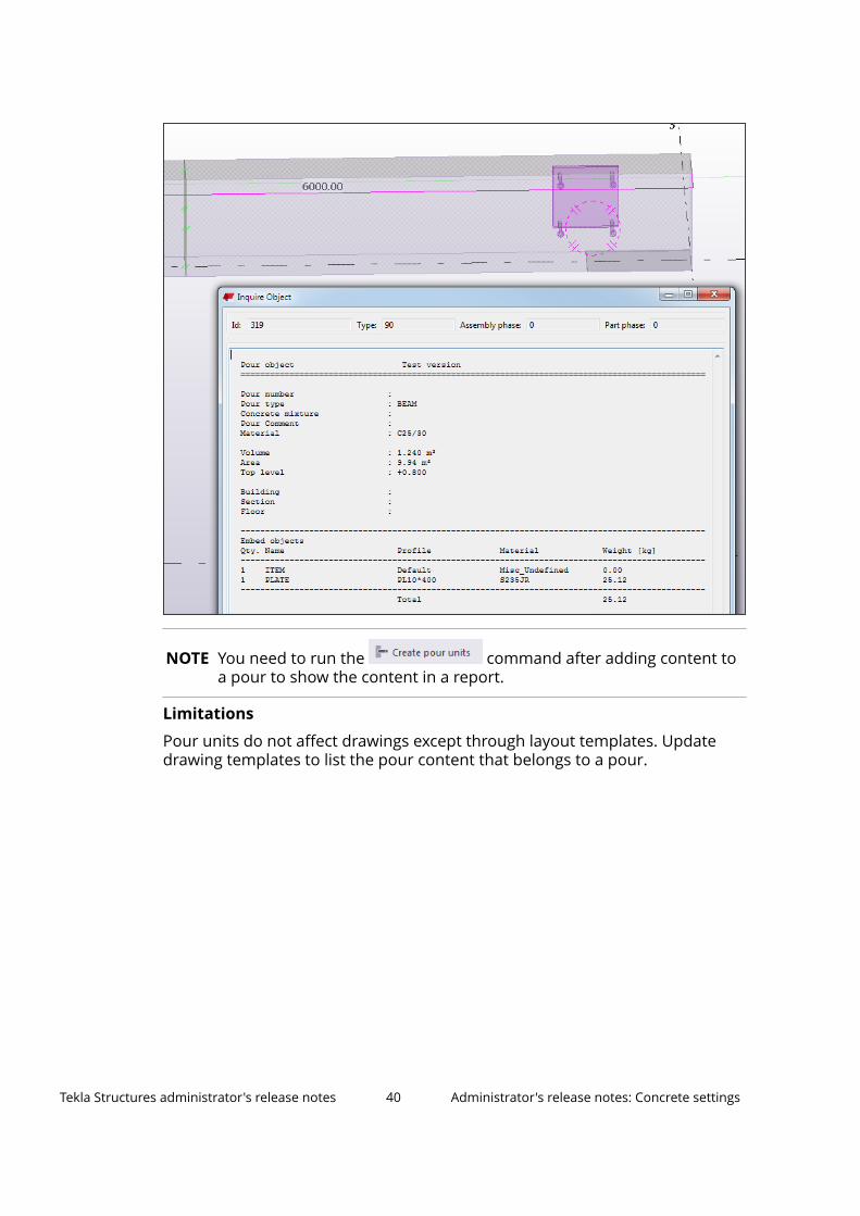
NOTE You need to run the command after adding content toa pour to show the content in a report.
Limitations
Pour units do not affect drawings except through layout templates. Updatedrawing templates to list the pour content that belongs to a pour.
Tekla Structures administrator's release notes 40 Administrator's release notes: Concrete settings
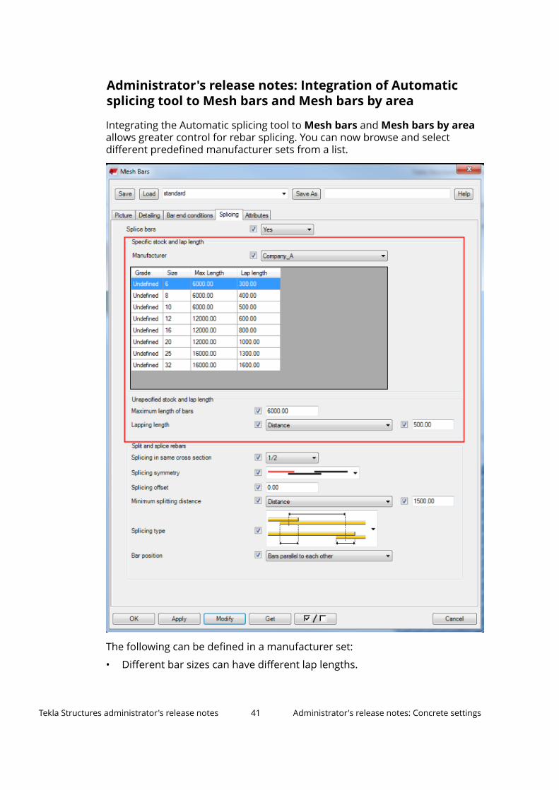
Administrator's release notes: Integration of Automaticsplicing tool to Mesh bars and Mesh bars by area
Integrating the Automatic splicing tool to Mesh bars and Mesh bars by areaallows greater control for rebar splicing. You can now browse and selectdifferent predefined manufacturer sets from a list.
The following can be defined in a manufacturer set:
• Different bar sizes can have different lap lengths.
Tekla Structures administrator's release notes 41 Administrator's release notes: Concrete settings
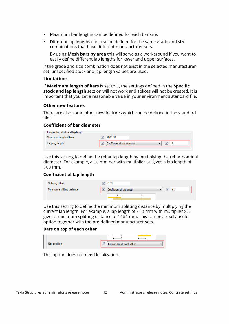
• Maximum bar lengths can be defined for each bar size.
• Different lap lengths can also be defined for the same grade and sizecombinations that have different manufacturer sets.
By using Mesh bars by area this will serve as a workaround if you want toeasily define different lap lengths for lower and upper surfaces.
If the grade and size combination does not exist in the selected manufacturerset, unspecified stock and lap length values are used.
Limitations
If Maximum length of bars is set to 0, the settings defined in the Specificstock and lap length section will not work and splices will not be created. It isimportant that you set a reasonable value in your environment's standard file.
Other new features
There are also some other new features which can be defined in the standardfiles.
Coefficient of bar diameter
Use this setting to define the rebar lap length by multiplying the rebar nominaldiameter. For example, a 10 mm bar with multiplier 50 gives a lap length of500 mm.
Coefficient of lap length
Use this setting to define the minimum splitting distance by multiplying thecurrent lap length. For example, a lap length of 400 mm with multiplier 2.5gives a minimum splitting distance of 1000 mm. This can be a really usefuloption together with the pre-defined manufacturer sets.
Bars on top of each other
This option does not need localization.
Tekla Structures administrator's release notes 42 Administrator's release notes: Concrete settings
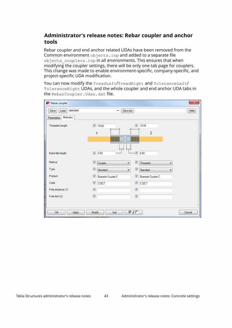
Administrator's release notes: Rebar coupler and anchortoolsRebar coupler and end anchor related UDAs have been removed from theCommon environment objects.inp and added to a separate fileobjects_couplers.inp in all environments. This ensures that whenmodifying the coupler settings, there will be only one tab page for couplers.This change was made to enable environment-specific, company-specific, andproject-specific UDA modification.
You can now modify the TreadLeft/TreadRight and ToleranceLeft/ToleranceRight UDAs, and the whole coupler and end anchor UDA tabs in the RebarCoupler.Udas.dat file.
Tekla Structures administrator's release notes 43 Administrator's release notes: Concrete settings
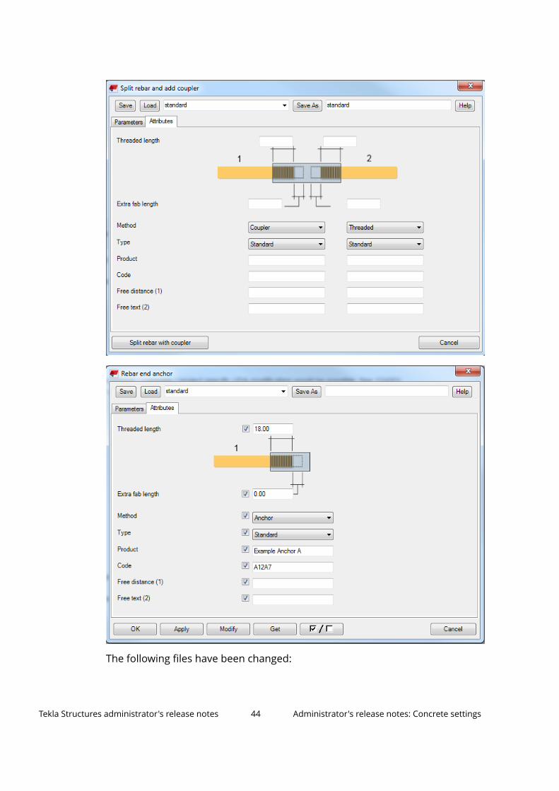
The following files have been changed:
Tekla Structures administrator's release notes 44 Administrator's release notes: Concrete settings

• RebarCoupler.Udas to also include Threaded length and Extra fablength
• rebar_with_couplers.tpl• RebarShapeManager.CustomProperties.datExample files AnchorExample.anchors.csv andCouplerExample.couplers.csv have been updated to be more instructiveand logical. These files can be found from the \system folder in the Commonenvironment.
Note the following:
• If your environment does not read the \inp folder in the Commonenvironment, remove the coupler and end anchor related UDAs from yourenvironment's objects.inp files, if those exist.
• If your environment does not read the \system folder in the Commonenvironment, add the files listed above to your environment's \systemfolder.
Tekla Structures administrator's release notes 45 Administrator's release notes: Concrete settings
2 Disclaimer
© 2016 Trimble Solutions Corporation and its licensors. All rights reserved.
This Software Manual has been developed for use with the referencedSoftware. Use of the Software, and use of this Software Manual are governedby a License Agreement. Among other provisions, the License Agreement setscertain warranties for the Software and this Manual, disclaims otherwarranties, limits recoverable damages, defines permitted uses of theSoftware, and determines whether you are an authorized user of the Software.All information set forth in this manual is provided with the warranty set forthin the License Agreement. Please refer to the License Agreement for importantobligations and applicable limitations and restrictions on your rights. Trimbledoes not guarantee that the text is free of technical inaccuracies ortypographical errors. Trimble reserves the right to make changes andadditions to this manual due to changes in the software or otherwise.
In addition, this Software Manual is protected by copyright law and byinternational treaties. Unauthorized reproduction, display, modification, ordistribution of this Manual, or any portion of it, may result in severe civil andcriminal penalties, and will be prosecuted to the full extent permitted by law.
Tekla, Tekla Structures, Tekla BIMsight, BIMsight, Tekla Civil, Tedds, Solve,Fastrak and Orion are either registered trademarks or trademarks of TrimbleSolutions Corporation in the European Union, the United States, and/or othercountries. More about Trimble Solutions trademarks: http://www.tekla.com/tekla-trademarks. Trimble is a registered trademark or trademark of TrimbleNavigation Limited in the European Union, in the United States and/or othercountries. More about Trimble trademarks: http://www.trimble.com/trademarks.aspx. Other product and company names mentioned in thisManual are or may be trademarks of their respective owners. By referring to athird-party product or brand, Trimble does not intend to suggest an affiliationwith or endorsement by such third party and disclaims any such affiliation orendorsement, except where otherwise expressly stated.
Portions of this software:
Open Cascade Express Mesh © 2015, by OPEN CASCADE S.A.S. All rightsreserved.
Disclaimer 46 Administrator's release notes: Concrete settings
D-Cubed 2D DCM © 2010 Siemens Industry Software Limited. All rightsreserved.
PolyBoolean C++ Library © 2001-2012 Complex A5 Co. Ltd. All rights reserved.
EPM toolkit © 1995-2006 Jotne EPM Technology a.s., Oslo, Norway. All rightsreserved.
FLY SDK - CAD SDK © 2012 VisualIntegrity™. All rights reserved.
Teigha © 2002-2015, Open Design Alliance. All rights reserved.
FlexNet © 2003-2015 Flexera Software LLC. All rights reserved.
This product contains proprietary and confidential technology, informationand creative works owned by Flexera Software LLC and its licensors, if any. Anyuse, copying, publication, distribution, display, modification, or transmission ofsuch technology in whole or in part in any form or by any means without theprior express written permission of Flexera Software LLC is strictly prohibited.Except where expressly provided by Flexera Software LLC in writing,possession of this technology shall not be construed to confer any license orrights under any Flexera Software LLC intellectual property rights, whether byestoppel, implication, or otherwise.
To see the third party open source software licenses, go to Tekla Structures,click File menu --> Help --> About Tekla Structures and then click the 3rdparty licenses option.
The elements of the software described in this Manual are protected byseveral patents and possibly pending patent applications in the United Statesand/or other countries. For more information go to page http://www.tekla.com/tekla-patents.
Disclaimer 47 Administrator's release notes: Concrete settings

Disclaimer 48 Administrator's release notes: Concrete settings