tekla struxml export -...
TRANSCRIPT
StruSoft AB www.strusoft.com Version: September 25th, 2017
Tekla StruXML Export User‟s Guide to Tekla Structures - FEM-Design Integration


Copyright
Copyright© 2017 by StruSoft. All rights reserved.
Content of this publication may not be reproduced or transmitted in any means without the written
permission of StruSoft AB.
Trademarks
FEM-Design® is a registered trademark of StruSoft.
Tekla® Structures is a registered trademark of Tekla.
Disclaimer
The Tekla StruXML Export is a tool that enables a link between Tekla Structures and FEM-Design.
Substantial amount of time and effort have gone into development and testing Tekla StruXML Export
tool. We did our best to ensure the reliability of the software and the accuracy of this document.
However, the user must accept that no warranty is given by the developers concerning accuracy of this
software or information found in this document.
Anyone that has doubts concerning the accuracy of the Tekla StruXML Export, or has suggestions
regarding development of the Tekla StruXML Export, is welcome to contact us at:
For support, please use: [email protected]. When sending support question, please
remember to always attach an original Tekla Structures model, FEM-Design model and a struxml file.
Current link versions
- Tekla StruXML Export 1.1.007
Compatibility
- Tekla Structures: version 18-21.1 and 2016, 2016i, 2017, 2017i
- FEM-Design 15.01 and later
Download
- FEM-Design Download Center
- StruSoft Installer
Additional materials
- Tekla – FEM-Design Integration
- Forum
- StruSoft Official YouTube Channel

Table of Contents
1. INTRODUCTION........................................................................................................................................... 7
1.1. MANUAL SCOPE .............................................................................................................................................. 7
1.2. INSTALLATION ................................................................................................................................................. 7
1.3. CONCEPT ....................................................................................................................................................... 7
1.4. WORKFLOW ................................................................................................................................................... 8
1.5. TRANSFERRED DATA ......................................................................................................................................... 8
2. TEKLA ANALYSIS MODEL ............................................................................................................................. 9
2.1. CREATING ANALYSIS MODEL ............................................................................................................................... 9
2.2. MODEL DISPLAY OPTIONS ................................................................................................................................ 12
2.2.1. Node and bar numbers visibility ....................................................................................................... 12
2.2.2. Physical objects visibility ................................................................................................................... 12
2.3. ANALYSIS MODEL CHECK ................................................................................................................................. 13
2.3.1. Analysis nodes colors ........................................................................................................................ 13
2.3.2. Checking warnings ............................................................................................................................ 13
2.4. ANALYSIS MODEL ADJUSTMENT ........................................................................................................................ 15
2.4.1. Analysis part properties .................................................................................................................... 15
2.4.2. Manual adjustment .......................................................................................................................... 22
3. EXPORTING TEKLA MODEL TO FEM-DESIGN ............................................................................................... 26
3.1. CREATE AN ANALYSIS MODEL ........................................................................................................................... 26
3.2. CHECK AND ADJUST AN ANALYSIS MODEL. ........................................................................................................... 28
3.3. TEKLA STRUXML EXPORT ............................................................................................................................... 32
3.4. OPEN STRUXML FILE IN FEM-DESIGN. ............................................................................................................... 36
3.5. ERRORS AT EXPORTING AN ANALYSIS MODEL. ...................................................................................................... 37
3.5.1. Lack of material definition ................................................................................................................ 37
3.5.2. Lack of material / section mapping .................................................................................................. 37
3.5.3. Invalid mapping ................................................................................................................................ 38
3.5.4. Bad surface geometry....................................................................................................................... 38
3.5.5. How to find a certain element in Tekla? ........................................................................................... 38
3.5.6. How to find a certain element in FEM-Design? ................................................................................ 42
Introduction
www.strusoft.com Page 6
NEW FEATURES, FIXES AND CHANGES COMPARED TO TEKLA STRUXML EXPORT 1.1.006
ADDED:
1. Compatibility with Tekla Structures 2017i.
FIXED:
2. Sections rotation was not exported correctly at some cases.
NEW FEATURES, FIXES AND CHANGES COMPARED TO TEKLA STRUXML EXPORT 1.1.005
ADDED:
1. Compatibility with Tekla Structures 2017.
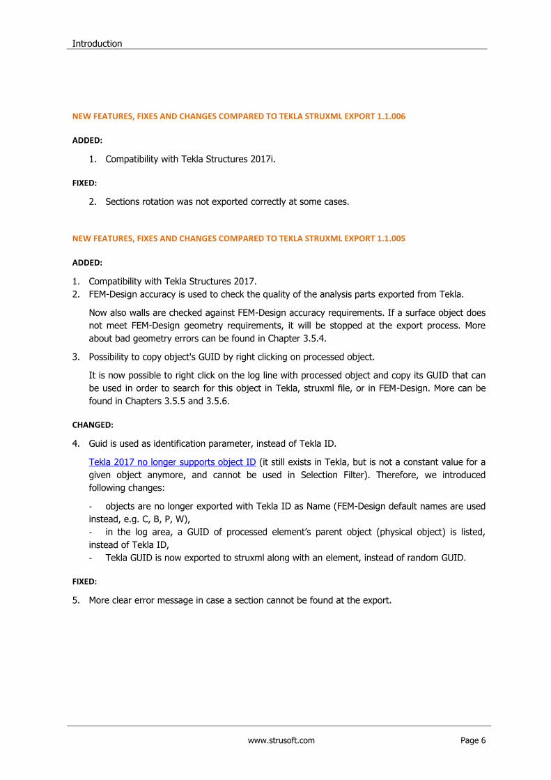
2. FEM-Design accuracy is used to check the quality of the analysis parts exported from Tekla.
Now also walls are checked against FEM-Design accuracy requirements. If a surface object does
not meet FEM-Design geometry requirements, it will be stopped at the export process. More
about bad geometry errors can be found in Chapter 3.5.4.
3. Possibility to copy object's GUID by right clicking on processed object.
It is now possible to right click on the log line with processed object and copy its GUID that can
be used in order to search for this object in Tekla, struxml file, or in FEM-Design. More can be
found in Chapters 3.5.5 and 3.5.6.
CHANGED:
4. Guid is used as identification parameter, instead of Tekla ID.
Tekla 2017 no longer supports object ID (it still exists in Tekla, but is not a constant value for a
given object anymore, and cannot be used in Selection Filter). Therefore, we introduced
following changes:
- objects are no longer exported with Tekla ID as Name (FEM-Design default names are used
instead, e.g. C, B, P, W),
- in the log area, a GUID of processed element‟s parent object (physical object) is listed,
instead of Tekla ID,
- Tekla GUID is now exported to struxml along with an element, instead of random GUID.
FIXED:
5. More clear error message in case a section cannot be found at the export.
Introduction
www.strusoft.com Page 7
1. Introduction
1.1. Manual scope
This document describes the concept behind the link between Tekla Structures and FEM-Design, and
explains how to exchange data between those two programs using the Tekla StruXML Export tool.
1.2. Installation
Download the latest version of Tekla StruXML Export from StruSoft Installer or from FEM-Design
Download Center and run the installation file.
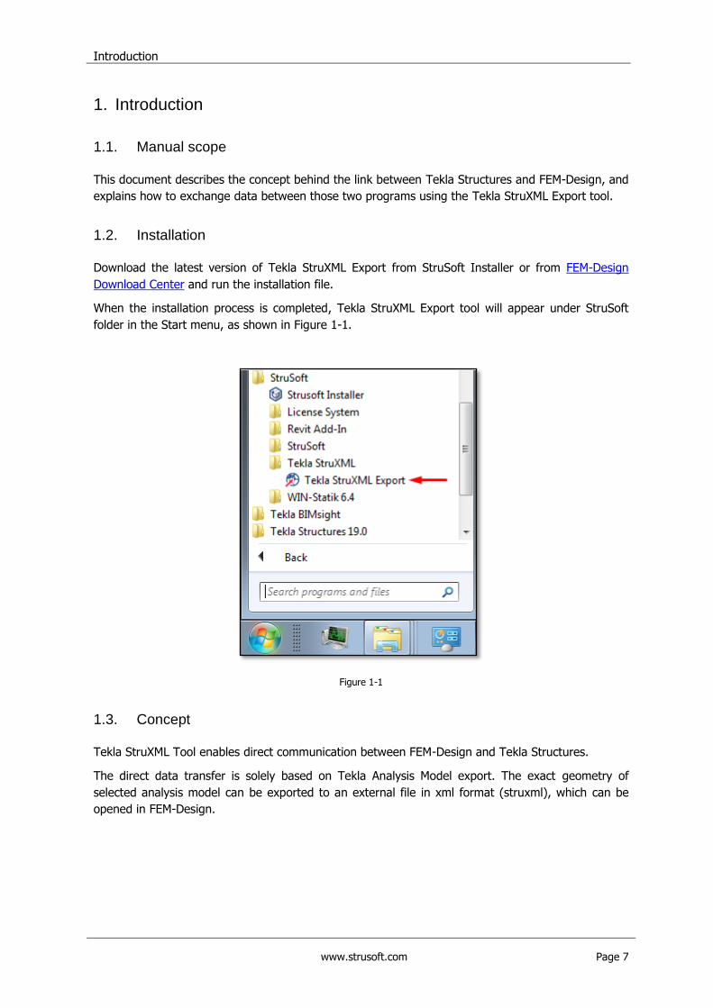
When the installation process is completed, Tekla StruXML Export tool will appear under StruSoft
folder in the Start menu, as shown in Figure 1-1.
Figure 1-1
1.3. Concept
Tekla StruXML Tool enables direct communication between FEM-Design and Tekla Structures.
The direct data transfer is solely based on Tekla Analysis Model export. The exact geometry of
selected analysis model can be exported to an external file in xml format (struxml), which can be
opened in FEM-Design.
Introduction
www.strusoft.com Page 8
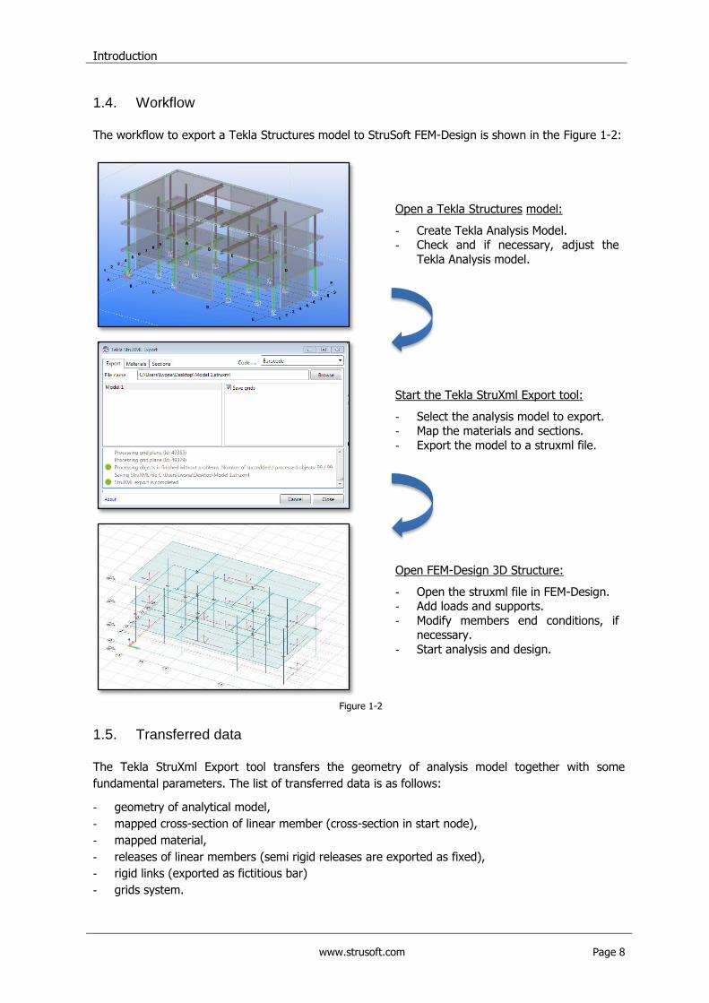
1.4. Workflow
The workflow to export a Tekla Structures model to StruSoft FEM-Design is shown in the Figure 1-2:
Open a Tekla Structures model:
- Create Tekla Analysis Model. - Check and if necessary, adjust the
Tekla Analysis model.
Start the Tekla StruXml Export tool:
- Select the analysis model to export. - Map the materials and sections.
- Export the model to a struxml file.
Figure 1-2
Open FEM-Design 3D Structure:
- Open the struxml file in FEM-Design. - Add loads and supports.
- Modify members end conditions, if necessary.
- Start analysis and design.
1.5. Transferred data
The Tekla StruXml Export tool transfers the geometry of analysis model together with some
fundamental parameters. The list of transferred data is as follows:
- geometry of analytical model,
- mapped cross-section of linear member (cross-section in start node),
- mapped material,
- releases of linear members (semi rigid releases are exported as fixed),
- rigid links (exported as fictitious bar)
- grids system.
Tekla Analysis Model
www.strusoft.com Page 9
2. Tekla Analysis Model
Tekla Analysis model is a structural representation of a Tekla physical model. Analysis model is used
for structural analysis and design, and can be exported into number of FEM-programs, including
StruSoft FEM-Design.
Tekla analysis model is generated automatically based on existing physical model geometry and
according to some predefined settings. In many cases the analysis model however, requires some
adjustments before it can be successfully exported to a FEM-program. Since the exact geometry of
analysis model is exported, it is extremely important to make sure that all analysis parts are
connected with each other and that the model is consistent.
Therefore, in this chapter some basic information regarding Tekla Analysis Model is gathered. Areas
such creating analysis model, model display options, model connectivity check, and model
adjustments are covered.
Please note, that to get the best overview of Tekla analysis model, it is highly advised to get familiar
with the official Tekla Analysis Guide.
2.1. Creating analysis model
More information:
What is Tekla analysis model? Creating Analysis model Analysis model properties
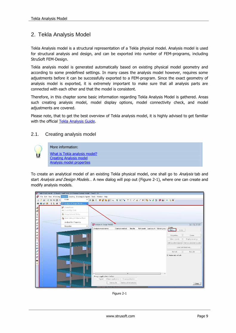
To create an analytical model of an existing Tekla physical model, one shall go to Analysis tab and
start Analysis and Design Models… A new dialog will pop out (Figure 2-1), where one can create and
modify analysis models.
Figure 2-1
Tekla Analysis Model
www.strusoft.com Page 10
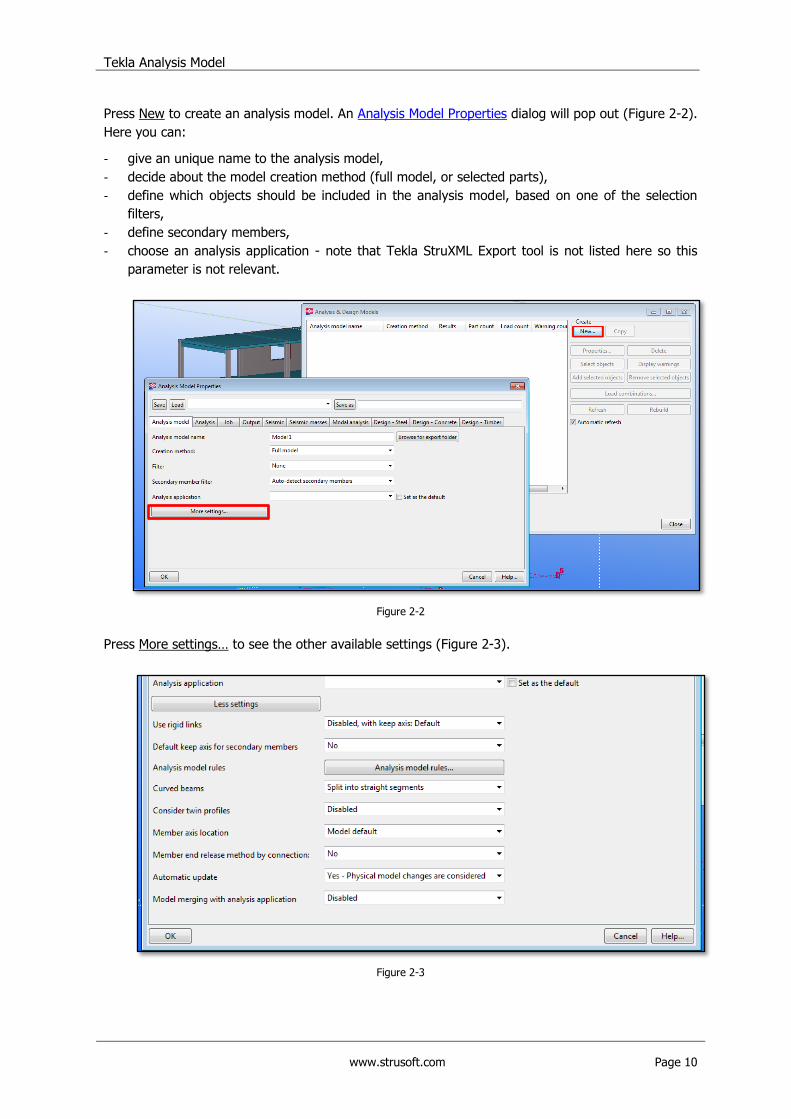
Press New to create an analysis model. An Analysis Model Properties dialog will pop out (Figure 2-2).
Here you can:
- give an unique name to the analysis model,
- decide about the model creation method (full model, or selected parts),
- define which objects should be included in the analysis model, based on one of the selection
filters,
- define secondary members,
- choose an analysis application - note that Tekla StruXML Export tool is not listed here so this
parameter is not relevant.
Figure 2-2
Press More settings… to see the other available settings (Figure 2-3).
Figure 2-3
Tekla Analysis Model
www.strusoft.com Page 11
Here, among other things, you can decide:
- if to include rigid links in the analysis model,
- location of the member analysis axis (neutral axis, reference axis, model default).
Note that „Automatic update‟ and „Model merging with analysis application‟ parameters are not
relevant in case of integration with FEM-Design.
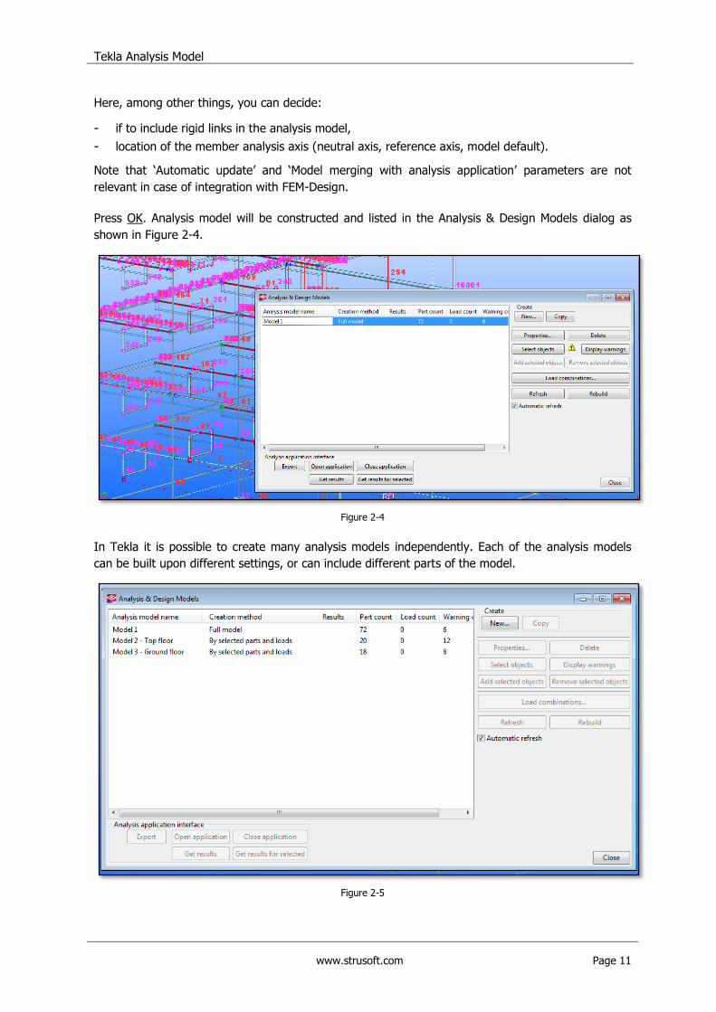
Press OK. Analysis model will be constructed and listed in the Analysis & Design Models dialog as
shown in Figure 2-4.
Figure 2-4
In Tekla it is possible to create many analysis models independently. Each of the analysis models
can be built upon different settings, or can include different parts of the model.
Figure 2-5
Tekla Analysis Model
www.strusoft.com Page 12
2.2. Model display options
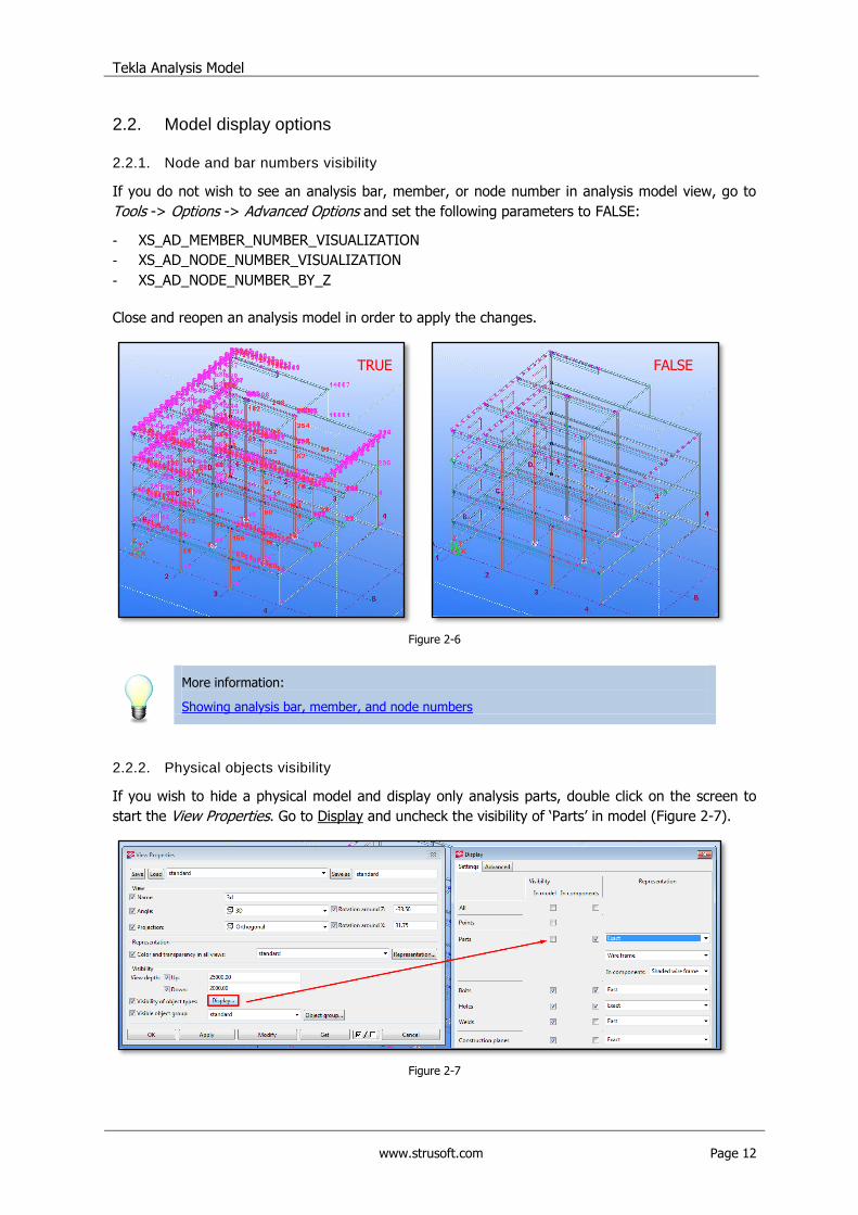
2.2.1. Node and bar numbers visibility
If you do not wish to see an analysis bar, member, or node number in analysis model view, go to
Tools -> Options -> Advanced Options and set the following parameters to FALSE:
- XS_AD_MEMBER_NUMBER_VISUALIZATION
- XS_AD_NODE_NUMBER_VISUALIZATION
- XS_AD_NODE_NUMBER_BY_Z
Close and reopen an analysis model in order to apply the changes.
Figure 2-6
More information:
Showing analysis bar, member, and node numbers
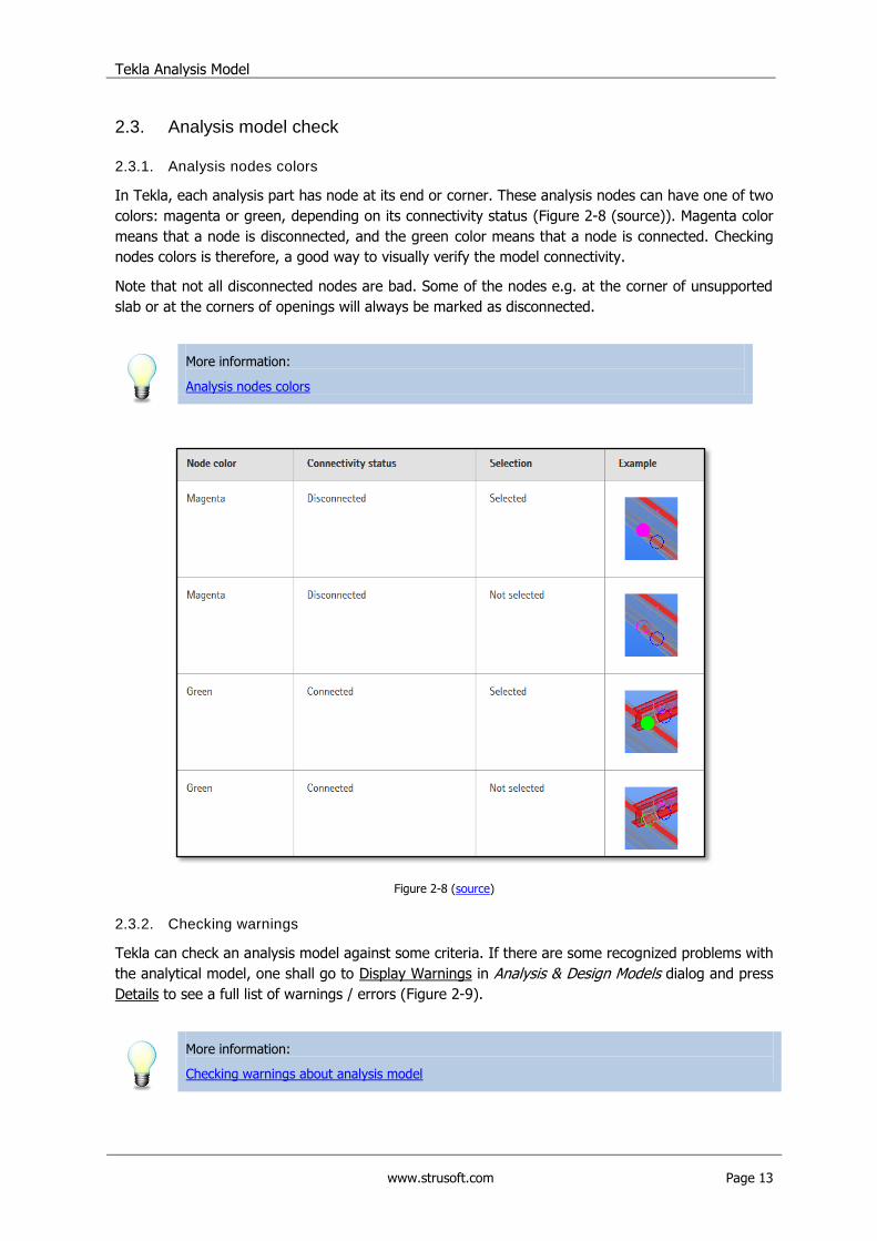
2.2.2. Physical objects visibility
If you wish to hide a physical model and display only analysis parts, double click on the screen to
start the View Properties. Go to Display and uncheck the visibility of „Parts‟ in model (Figure 2-7).
Figure 2-7
TRUE FALSE
Tekla Analysis Model
www.strusoft.com Page 13
2.3. Analysis model check
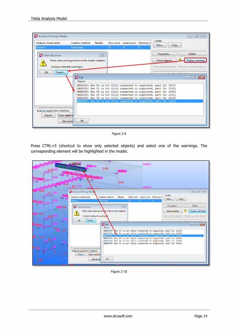
2.3.1. Analysis nodes colors
In Tekla, each analysis part has node at its end or corner. These analysis nodes can have one of two
colors: magenta or green, depending on its connectivity status (Figure 2-8 (source)). Magenta color
means that a node is disconnected, and the green color means that a node is connected. Checking
nodes colors is therefore, a good way to visually verify the model connectivity.
Note that not all disconnected nodes are bad. Some of the nodes e.g. at the corner of unsupported
slab or at the corners of openings will always be marked as disconnected.
More information:
Analysis nodes colors
Figure 2-8 (source)
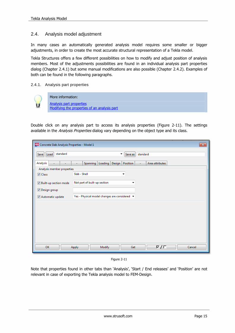
2.3.2. Checking warnings
Tekla can check an analysis model against some criteria. If there are some recognized problems with
the analytical model, one shall go to Display Warnings in Analysis & Design Models dialog and press
Details to see a full list of warnings / errors (Figure 2-9).
More information:
Checking warnings about analysis model
Tekla Analysis Model
www.strusoft.com Page 14
Figure 2-9
Press CTRL+5 (shortcut to show only selected objects) and select one of the warnings. The
corresponding element will be highlighted in the model.
Figure 2-10
Tekla Analysis Model
www.strusoft.com Page 15
2.4. Analysis model adjustment
In many cases an automatically generated analysis model requires some smaller or bigger
adjustments, in order to create the most accurate structural representation of a Tekla model.
Tekla Structures offers a few different possibilities on how to modify and adjust position of analysis
members. Most of the adjustments possibilities are found in an individual analysis part properties
dialog (Chapter 2.4.1) but some manual modifications are also possible (Chapter 2.4.2). Examples of
both can be found in the following paragraphs.
2.4.1. Analysis part properties
More information:
Analysis part properties Modifying the properties of an analysis part
Double click on any analysis part to access its analysis properties (Figure 2-11). The settings
available in the Analysis Properties dialog vary depending on the object type and its class.
Figure 2-11
Note that properties found in other tabs than „Analysis‟, „Start / End releases‟ and „Position‟ are not
relevant in case of exporting the Tekla analysis model to FEM-Design.
Tekla Analysis Model
www.strusoft.com Page 16
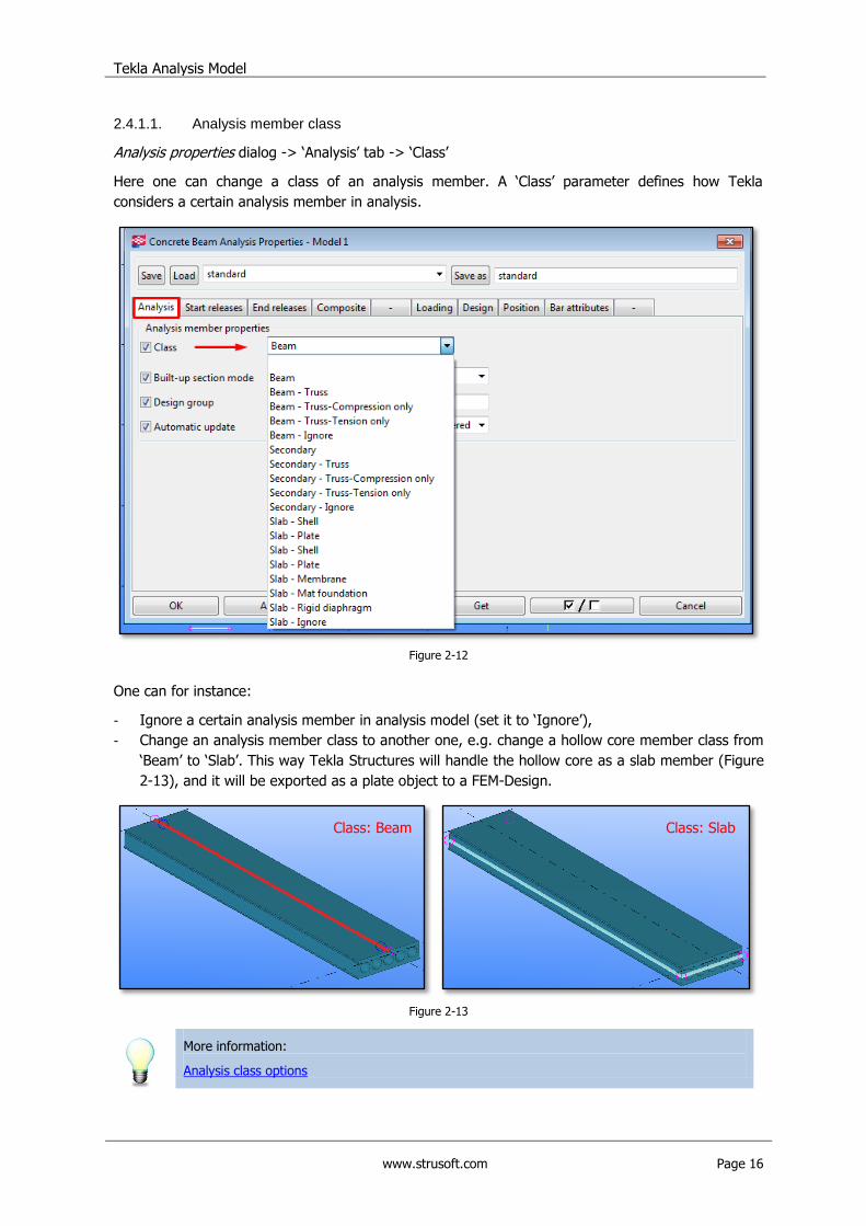
2.4.1.1. Analysis member class
Analysis properties dialog -> „Analysis‟ tab -> „Class‟
Here one can change a class of an analysis member. A „Class‟ parameter defines how Tekla
considers a certain analysis member in analysis.
Figure 2-12
One can for instance:
- Ignore a certain analysis member in analysis model (set it to „Ignore‟),
- Change an analysis member class to another one, e.g. change a hollow core member class from
„Beam‟ to „Slab‟. This way Tekla Structures will handle the hollow core as a slab member (Figure
2-13), and it will be exported as a plate object to a FEM-Design.
Figure 2-13
More information:
Analysis class options
Class: Beam Class: Slab
Tekla Analysis Model
www.strusoft.com Page 17
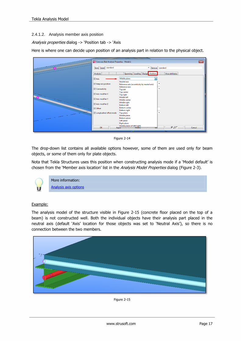
2.4.1.2. Analysis member axis position
Analysis properties dialog -> „Position tab -> „Axis
Here is where one can decide upon position of an analysis part in relation to the physical object.
Figure 2-14
The drop-down list contains all available options however, some of them are used only for beam
objects, or some of them only for plate objects.
Nota that Tekla Structures uses this position when constructing analysis mode if a „Model default‟ is
chosen from the „Member axis location‟ list in the Analysis Model Properties dialog (Figure 2-3).
More information:
Analysis axis options
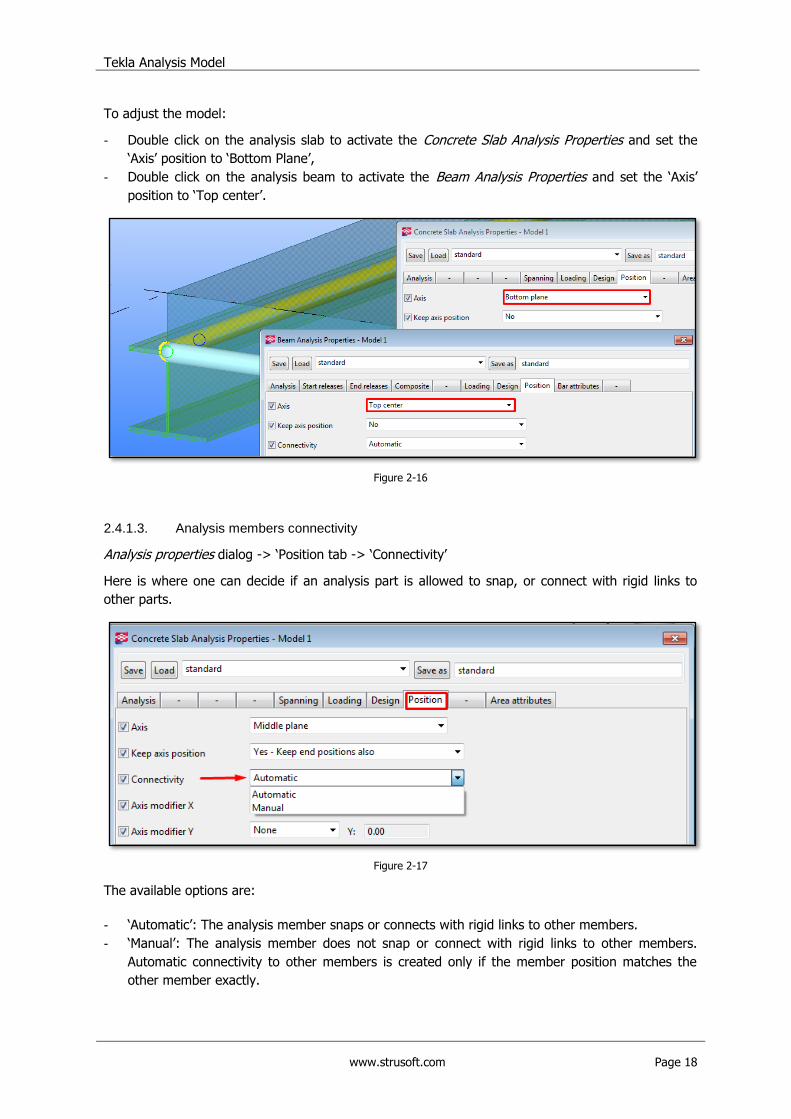
Example:
The analysis model of the structure visible in Figure 2-15 (concrete floor placed on the top of a
beam) is not constructed well. Both the individual objects have their analysis part placed in the
neutral axis (default „Axis‟ location for those objects was set to „Neutral Axis‟), so there is no
connection between the two members.
Figure 2-15
Tekla Analysis Model
www.strusoft.com Page 18
To adjust the model:
- Double click on the analysis slab to activate the Concrete Slab Analysis Properties and set the
„Axis‟ position to „Bottom Plane‟,
- Double click on the analysis beam to activate the Beam Analysis Properties and set the „Axis‟
position to „Top center‟.
Figure 2-16
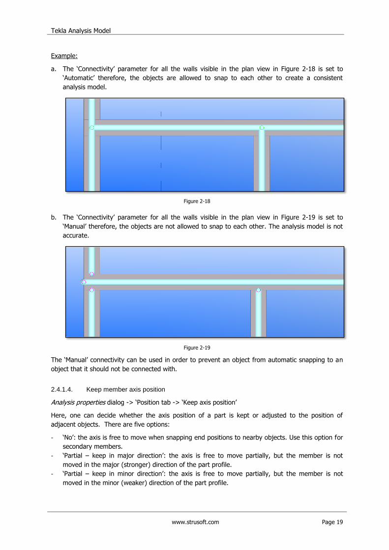
2.4.1.3. Analysis members connectivity
Analysis properties dialog -> „Position tab -> „Connectivity‟
Here is where one can decide if an analysis part is allowed to snap, or connect with rigid links to
other parts.
Figure 2-17
The available options are:
- „Automatic‟: The analysis member snaps or connects with rigid links to other members.
- „Manual‟: The analysis member does not snap or connect with rigid links to other members.
Automatic connectivity to other members is created only if the member position matches the
other member exactly.
Tekla Analysis Model
www.strusoft.com Page 19
Example:
a. The „Connectivity‟ parameter for all the walls visible in the plan view in Figure 2-18 is set to
„Automatic‟ therefore, the objects are allowed to snap to each other to create a consistent
analysis model.
Figure 2-18
b. The „Connectivity‟ parameter for all the walls visible in the plan view in Figure 2-19 is set to
„Manual‟ therefore, the objects are not allowed to snap to each other. The analysis model is not
accurate.
Figure 2-19
The „Manual‟ connectivity can be used in order to prevent an object from automatic snapping to an
object that it should not be connected with.
2.4.1.4. Keep member axis position
Analysis properties dialog -> „Position tab -> „Keep axis position‟
Here, one can decide whether the axis position of a part is kept or adjusted to the position of
adjacent objects. There are five options:
- „No‟: the axis is free to move when snapping end positions to nearby objects. Use this option for
secondary members.
- „Partial – keep in major direction‟: the axis is free to move partially, but the member is not
moved in the major (stronger) direction of the part profile.
- „Partial – keep in minor direction‟: the axis is free to move partially, but the member is not
moved in the minor (weaker) direction of the part profile.
Tekla Analysis Model
www.strusoft.com Page 20
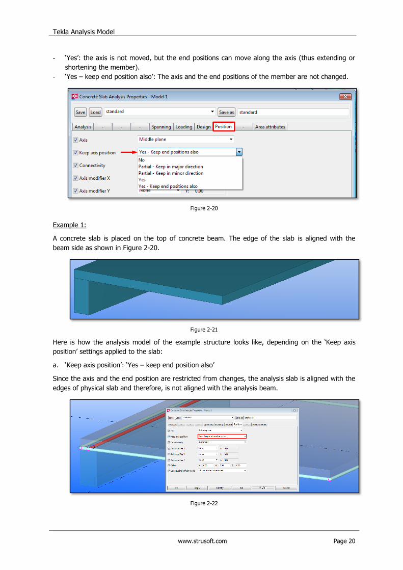
- „Yes‟: the axis is not moved, but the end positions can move along the axis (thus extending or
shortening the member).
- „Yes – keep end position also‟: The axis and the end positions of the member are not changed.
Figure 2-20
Example 1:
A concrete slab is placed on the top of concrete beam. The edge of the slab is aligned with the
beam side as shown in Figure 2-20.
Figure 2-21
Here is how the analysis model of the example structure looks like, depending on the „Keep axis
position‟ settings applied to the slab:
a. „Keep axis position‟: „Yes – keep end position also‟
Since the axis and the end position are restricted from changes, the analysis slab is aligned with the
edges of physical slab and therefore, is not aligned with the analysis beam.
Figure 2-22
Tekla Analysis Model
www.strusoft.com Page 21
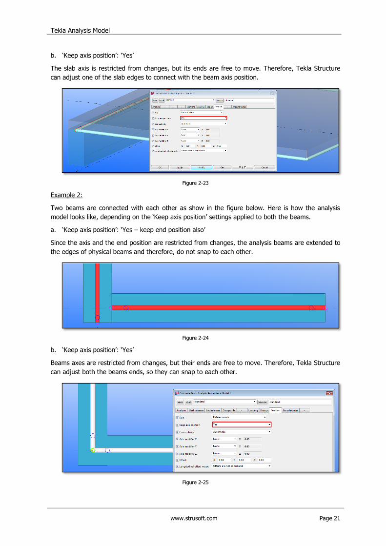
b. „Keep axis position‟: „Yes‟
The slab axis is restricted from changes, but its ends are free to move. Therefore, Tekla Structure
can adjust one of the slab edges to connect with the beam axis position.
Figure 2-23
Example 2:
Two beams are connected with each other as show in the figure below. Here is how the analysis
model looks like, depending on the „Keep axis position‟ settings applied to both the beams.
a. „Keep axis position‟: „Yes – keep end position also‟
Since the axis and the end position are restricted from changes, the analysis beams are extended to
the edges of physical beams and therefore, do not snap to each other.
Figure 2-24
b. „Keep axis position‟: „Yes‟
Beams axes are restricted from changes, but their ends are free to move. Therefore, Tekla Structure
can adjust both the beams ends, so they can snap to each other.
Figure 2-25
Tekla Analysis Model
www.strusoft.com Page 22
2.4.2. Manual adjustment
2.4.2.1. Move special
Analysis nodes and analysis parts can be moved, just as other Tekla objects. A particularly useful
command to do so is „Move Special‟ -> „Linear‟.
Note that any change applied to the analysis part does not influence the physical object.
More information:
Moving an object linearly to a new position
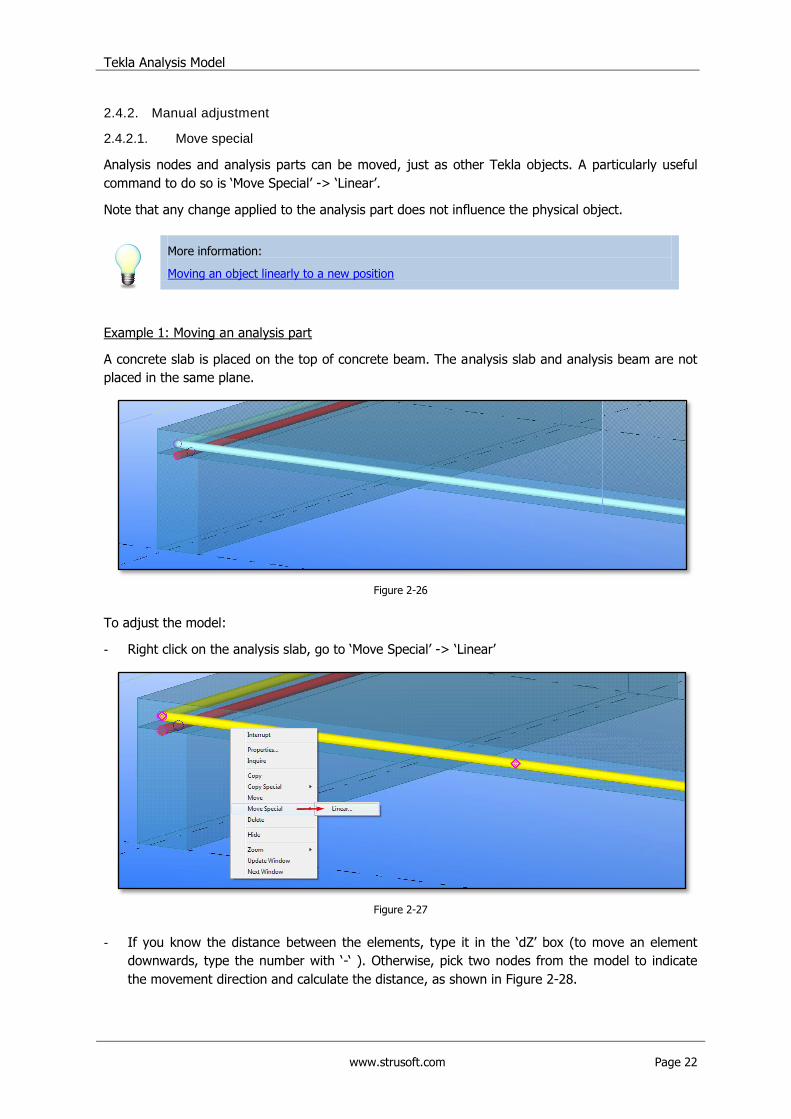
Example 1: Moving an analysis part
A concrete slab is placed on the top of concrete beam. The analysis slab and analysis beam are not
placed in the same plane.
Figure 2-26
To adjust the model:
- Right click on the analysis slab, go to „Move Special‟ -> „Linear‟
Figure 2-27
- If you know the distance between the elements, type it in the „dZ‟ box (to move an element
downwards, type the number with „-„ ). Otherwise, pick two nodes from the model to indicate
the movement direction and calculate the distance, as shown in Figure 2-28.
Tekla Analysis Model
www.strusoft.com Page 23
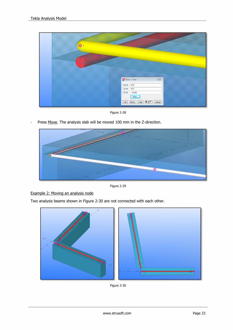
Figure 2-28
- Press Move. The analysis slab will be moved 100 mm in the Z-direction.
Figure 2-29
Example 2: Moving an analysis node
Two analysis beams shown in Figure 2-30 are not connected with each other.
Figure 2-30
Tekla Analysis Model
www.strusoft.com Page 24
To adjust the model:
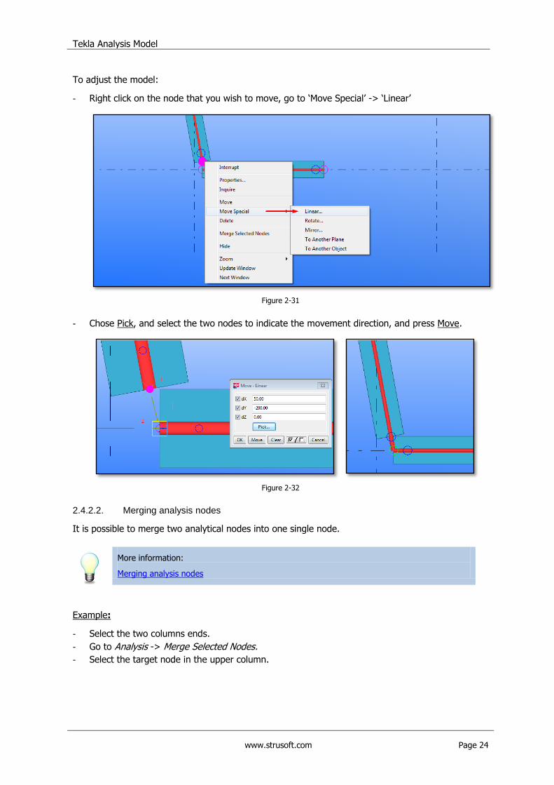
- Right click on the node that you wish to move, go to „Move Special‟ -> „Linear‟
Figure 2-31
- Chose Pick, and select the two nodes to indicate the movement direction, and press Move.
Figure 2-32
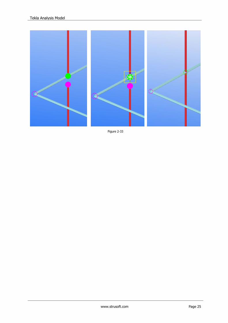
2.4.2.2. Merging analysis nodes
It is possible to merge two analytical nodes into one single node.
More information:
Merging analysis nodes
Example:
- Select the two columns ends.
- Go to Analysis -> Merge Selected Nodes.
- Select the target node in the upper column.
Tekla Analysis Model
www.strusoft.com Page 25
Figure 2-33
Exporting Tekla Structures model to FEM-Design
www.strusoft.com Page 26
3. Exporting Tekla model to FEM-Design
This chapter contains a step by step guide on how to export a Tekla Structures model to StruSoft
FEM-Design. A sample model is used to demonstrate the process.
3.1. Create an analysis model
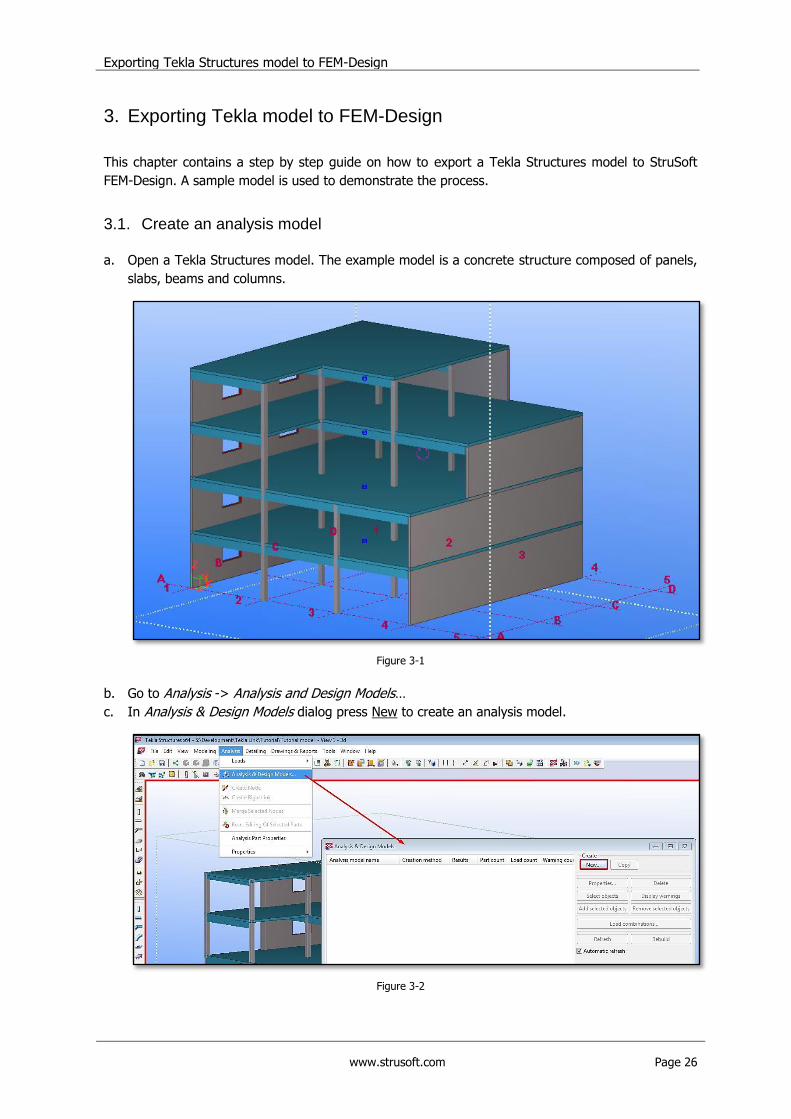
a. Open a Tekla Structures model. The example model is a concrete structure composed of panels,
slabs, beams and columns.
Figure 3-1
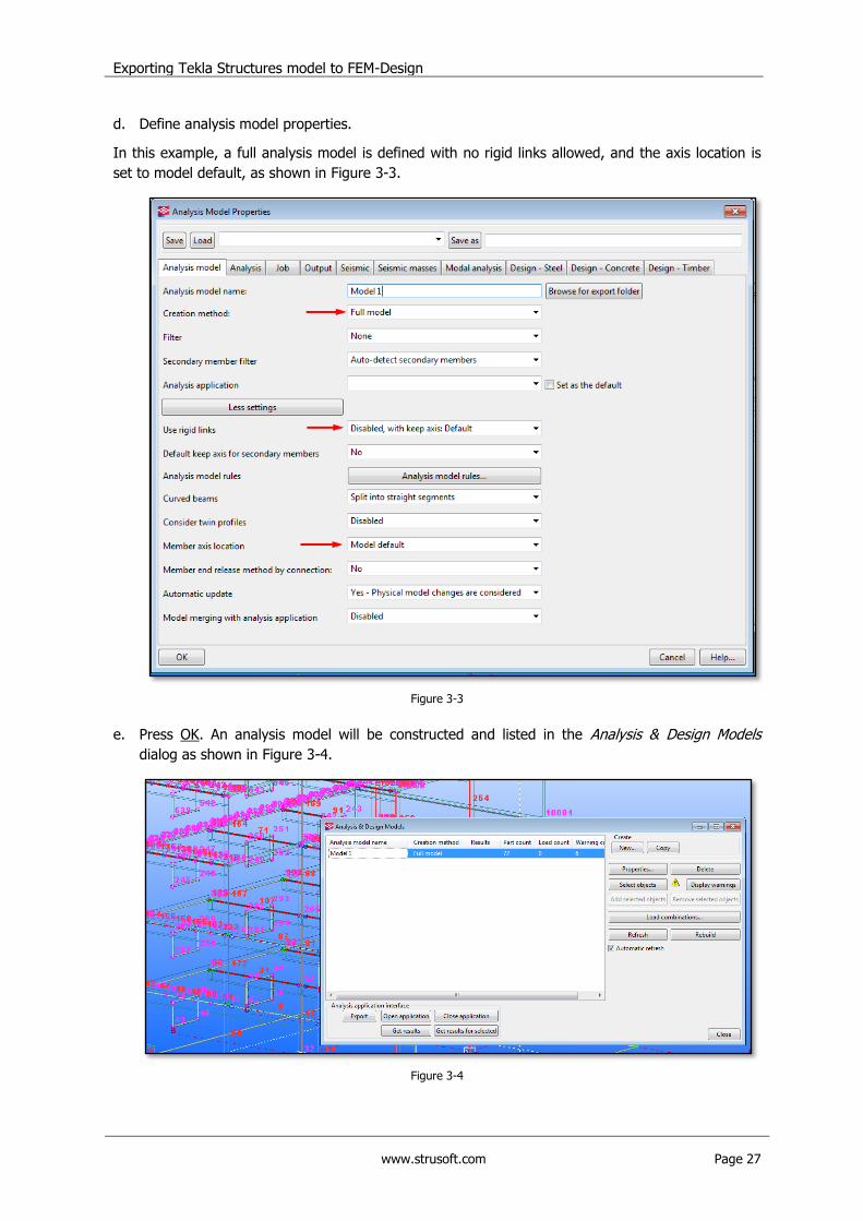
b. Go to Analysis -> Analysis and Design Models…
c. In Analysis & Design Models dialog press New to create an analysis model.
Figure 3-2
Exporting Tekla Structures model to FEM-Design
www.strusoft.com Page 27
d. Define analysis model properties.
In this example, a full analysis model is defined with no rigid links allowed, and the axis location is
set to model default, as shown in Figure 3-3.
Figure 3-3
e. Press OK. An analysis model will be constructed and listed in the Analysis & Design Models
dialog as shown in Figure 3-4.
Figure 3-4
Exporting Tekla Structures model to FEM-Design
www.strusoft.com Page 28
3.2. Check and adjust an analysis model.
a. In the first (optional) step turn off the visibility of members and nodes numbers.
Go to Tools -> Options -> Advanced Options, and set the following parameters to FALSE:
- XS_AD_MEMBER_NUMBER_VISUALIZATION
- XS_AD_NODE_NUMBER_VISUALIZATION
- XS_AD_NODE_NUMBER_BY_Z
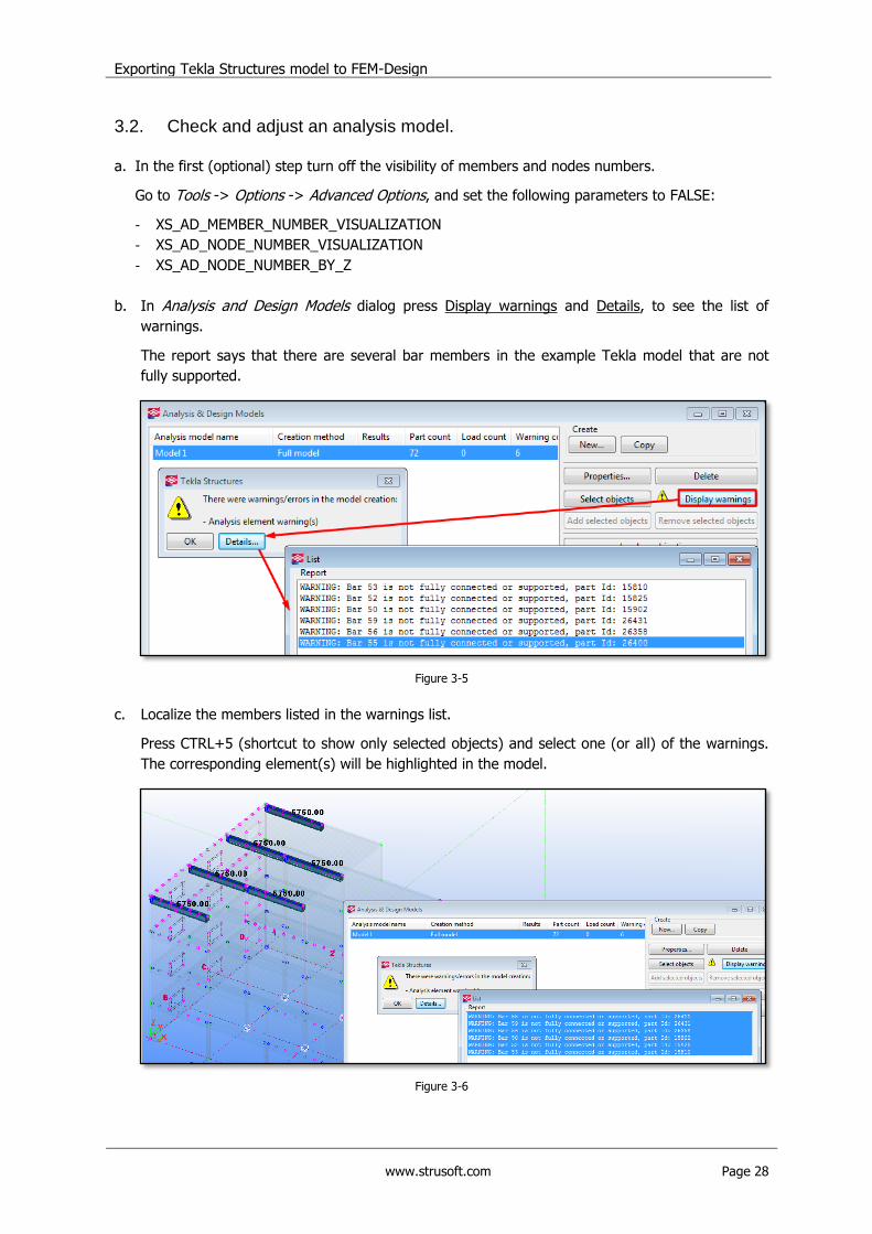
b. In Analysis and Design Models dialog press Display warnings and Details, to see the list of
warnings.
The report says that there are several bar members in the example Tekla model that are not
fully supported.
Figure 3-5
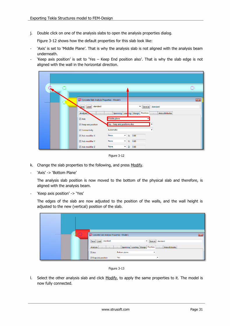
c. Localize the members listed in the warnings list.
Press CTRL+5 (shortcut to show only selected objects) and select one (or all) of the warnings.
The corresponding element(s) will be highlighted in the model.
Figure 3-6

Exporting Tekla Structures model to FEM-Design
www.strusoft.com Page 29
d. Zoom into each of the members to check the exact problem.
In this example the problem is that analysis axis of each of the listed beams do not connect with
the adjacent objects (walls, columns), as shown in Figure 3-7.
Figure 3-7
e. Check the analysis properties of the listed members.
To do so, double click on one of the analysis beams in the model, or right click on the warning
message and choose Analysis Properties.
Figure 3-8
f. Change „Keep Axis position‟ parameter from „Yes – Keep end position also‟ to „Yes‟. Press Modify.
Figure 3-9

Exporting Tekla Structures model to FEM-Design
www.strusoft.com Page 30
g. Select next unsupported element (in the model or in the warning list) and press Modify to apply
the new settings. Apply the properties to all listed beams.
h. There are no more unsupported elements in the model, but not all the model inconsistencies are
listed in the Warnings list. Therefore, check the model visually and verify the nodes connectivity.
Visual checking the example model shows that there are some disconnected nodes (in magenta
color) on the top two floors. The nodes are located along the floor perimeter as shown in Figure
3-10.
Figure 3-10
i. Zoom into the disconnected nodes area. It looks like the analysis slabs are not connected with
beams underneath, and that they are not well connected to the walls, as shown in Figure 3-11.
Figure 3-11
Exporting Tekla Structures model to FEM-Design
www.strusoft.com Page 31
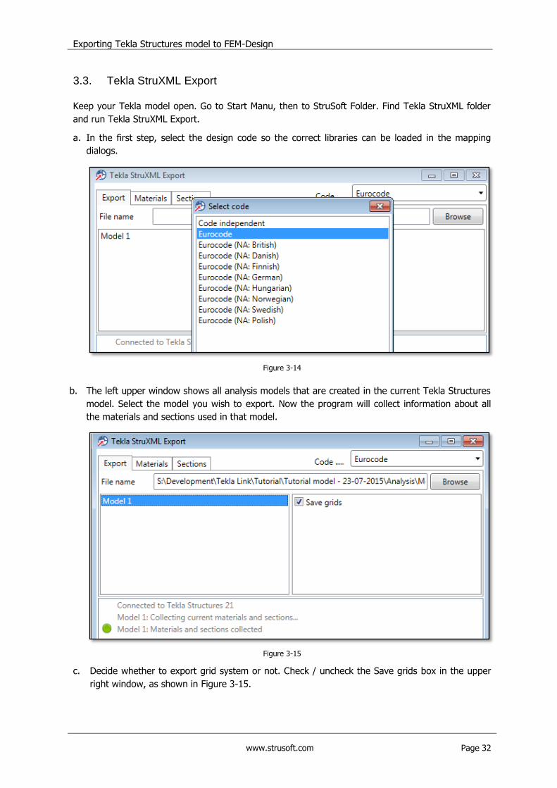
j. Double click on one of the analysis slabs to open the analysis properties dialog.
Figure 3-12 shows how the default properties for this slab look like:
- „Axis‟ is set to „Middle Plane‟. That is why the analysis slab is not aligned with the analysis beam
underneath.
- „Keep axis position‟ is set to „Yes – Keep End position also‟. That is why the slab edge is not
aligned with the wall in the horizontal direction.
Figure 3-12
k. Change the slab properties to the following, and press Modify.
- „Axis‟ -> „Bottom Plane‟
The analysis slab position is now moved to the bottom of the physical slab and therefore, is
aligned with the analysis beam.
- „Keep axis position‟ -> „Yes‟
The edges of the slab are now adjusted to the position of the walls, and the wall height is
adjusted to the new (vertical) position of the slab.
Figure 3-13
l. Select the other analysis slab and click Modify, to apply the same properties to it. The model is
now fully connected.
Exporting Tekla Structures model to FEM-Design
www.strusoft.com Page 32
3.3. Tekla StruXML Export
Keep your Tekla model open. Go to Start Manu, then to StruSoft Folder. Find Tekla StruXML folder
and run Tekla StruXML Export.
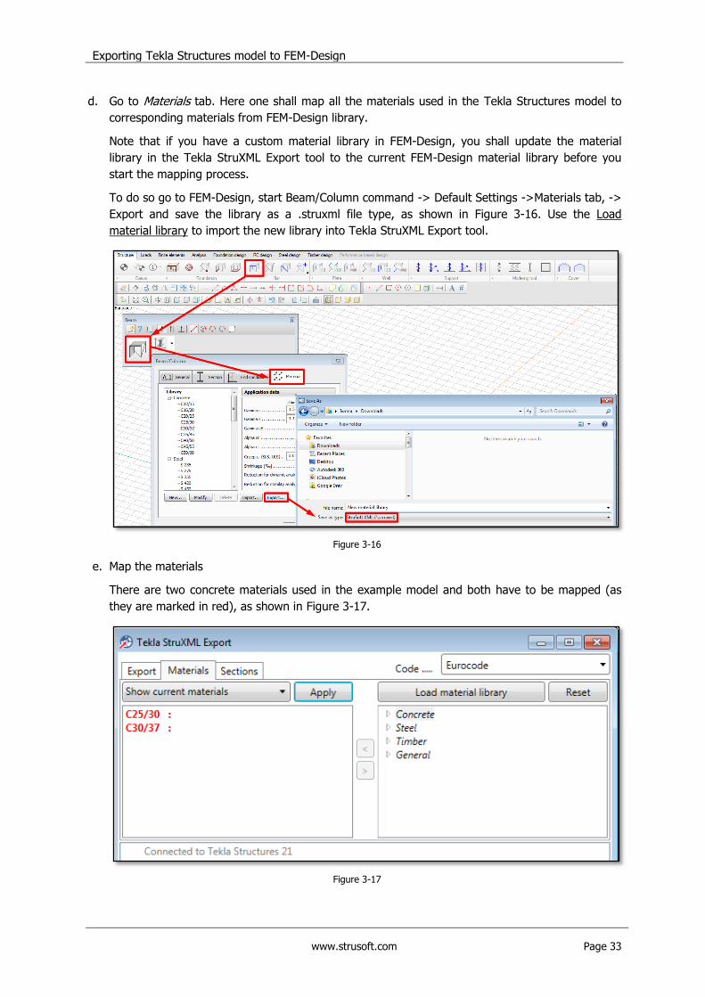
a. In the first step, select the design code so the correct libraries can be loaded in the mapping
dialogs.
Figure 3-14
b. The left upper window shows all analysis models that are created in the current Tekla Structures
model. Select the model you wish to export. Now the program will collect information about all
the materials and sections used in that model.
Figure 3-15
c. Decide whether to export grid system or not. Check / uncheck the Save grids box in the upper
right window, as shown in Figure 3-15.
Exporting Tekla Structures model to FEM-Design
www.strusoft.com Page 33
d. Go to Materials tab. Here one shall map all the materials used in the Tekla Structures model to
corresponding materials from FEM-Design library.
Note that if you have a custom material library in FEM-Design, you shall update the material
library in the Tekla StruXML Export tool to the current FEM-Design material library before you
start the mapping process.
To do so go to FEM-Design, start Beam/Column command -> Default Settings ->Materials tab, ->
Export and save the library as a .struxml file type, as shown in Figure 3-16. Use the Load
material library to import the new library into Tekla StruXML Export tool.
Figure 3-16
e. Map the materials
There are two concrete materials used in the example model and both have to be mapped (as
they are marked in red), as shown in Figure 3-17.
Figure 3-17
Exporting Tekla Structures model to FEM-Design
www.strusoft.com Page 34
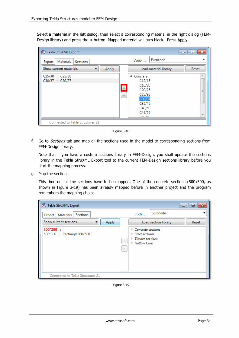
Select a material in the left dialog, then select a corresponding material in the right dialog (FEM-
Design library) and press the < button. Mapped material will turn black. Press Apply.
Figure 3-18
f. Go to Sections tab and map all the sections used in the model to corresponding sections from
FEM-Design library.
Note that if you have a custom sections library in FEM-Design, you shall update the sections
library in the Tekla StruXML Export tool to the current FEM-Design sections library before you
start the mapping process.
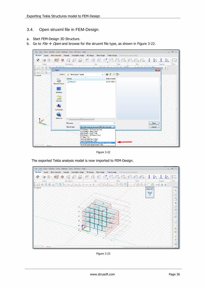
g. Map the sections.
This time not all the sections have to be mapped. One of the concrete sections (500x300, as
shown in Figure 3-19) has been already mapped before in another project and the program
remembers the mapping choice.
Figure 3-19

Exporting Tekla Structures model to FEM-Design
www.strusoft.com Page 35
Map the remaining section. The procedure is the same as in case of materials mapping. Press
Apply when you are done.
Figure 3-20
h. Go back to Export tab.
Press Browse to find a new name and location for the export file (if necessary) and press Export.
i. Check the export status and if there were any problems with exporting the model.
Exporting the example model was successful. The report says that 114 out of 114 objects in the
analysis model (including grids system) have been exported to the struxml file.
Figure 3-21
Exporting Tekla Structures model to FEM-Design
www.strusoft.com Page 36
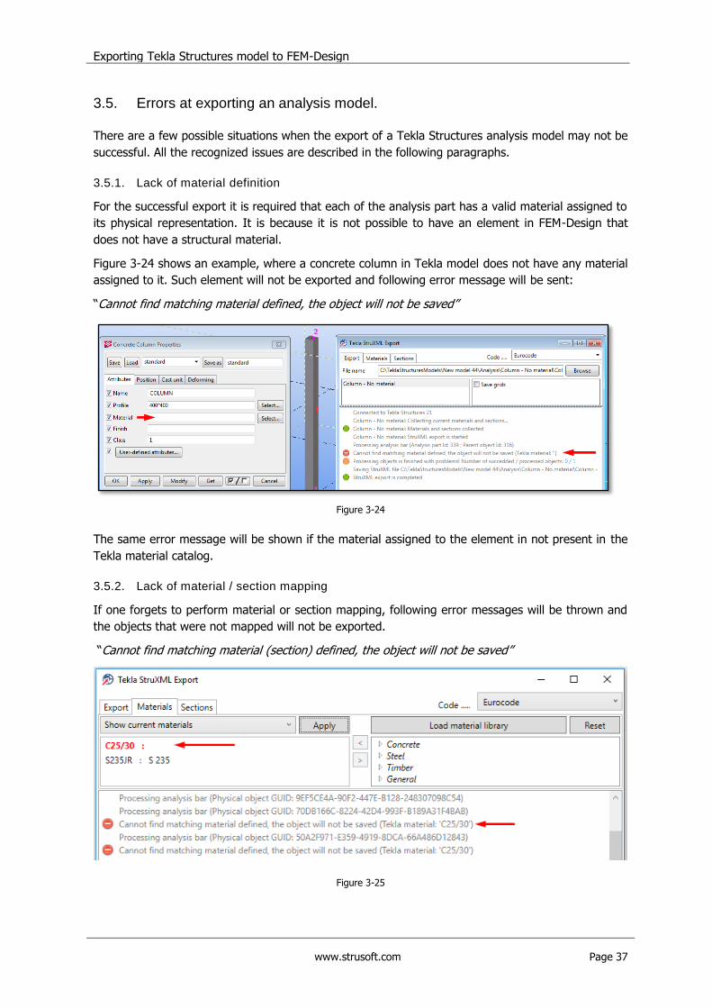
3.4. Open struxml file in FEM-Design.
a. Start FEM-Design 3D Structure.
b. Go to File Open and browse for the struxml file type, as shown in Figure 3-22.
Figure 3-22
The exported Tekla analysis model is now imported to FEM-Design.
Figure 3-23
Exporting Tekla Structures model to FEM-Design
www.strusoft.com Page 37
3.5. Errors at exporting an analysis model.
There are a few possible situations when the export of a Tekla Structures analysis model may not be
successful. All the recognized issues are described in the following paragraphs.
3.5.1. Lack of material definition
For the successful export it is required that each of the analysis part has a valid material assigned to
its physical representation. It is because it is not possible to have an element in FEM-Design that
does not have a structural material.
Figure 3-24 shows an example, where a concrete column in Tekla model does not have any material
assigned to it. Such element will not be exported and following error message will be sent:
“Cannot find matching material defined, the object will not be saved”
Figure 3-24
The same error message will be shown if the material assigned to the element in not present in the
Tekla material catalog.
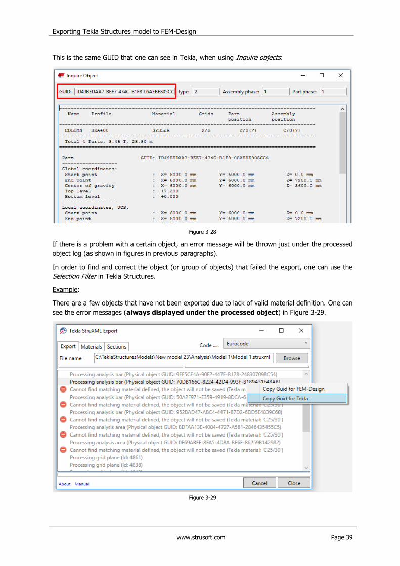
3.5.2. Lack of material / section mapping
If one forgets to perform material or section mapping, following error messages will be thrown and
the objects that were not mapped will not be exported.
“Cannot find matching material (section) defined, the object will not be saved”
Figure 3-25

Exporting Tekla Structures model to FEM-Design
www.strusoft.com Page 38
3.5.3. Invalid mapping
If one accidentally maps a material to a wrong type of section, or the opposite, a following error
messages will be thrown:
“Invalid mapped material and section combination. The bar will not be saved ()”
Figure 3-26
3.5.4. Bad surface geometry
In FEM-Design it is required that surface elements (plates and walls) are defined in one plane only,
with a certain accuracy. In Tekla Structure however, it is possible that an analysis slab or analysis
wall has nodes that are out of plane. In this case, one of the following error messages will be thrown
and such element will not be exported:
- “The analysis area has out of plane point(s)! The analysis area will not be saved!”
- “The wall vertically does not meet FEM-Design requirements! The analysis area will not be
saved!”
- “Improper region! The analysis area will not be saved!”
In each case, one can search for the bad object using the method given in Chapter 3.5.5, and try to
fix the analysis part of the object (using methods given in Chapter 2.4.
3.5.5. How to find a certain element in Tekla?
When exporting a model to struxml, Tekla StruXML Export shows a GUID of a parent object
(physical member) for each processed object. The message in the log dialog looks like this:
Figure 3-27
Exporting Tekla Structures model to FEM-Design
www.strusoft.com Page 39
This is the same GUID that one can see in Tekla, when using Inquire objects:
Figure 3-28
If there is a problem with a certain object, an error message will be thrown just under the processed
object log (as shown in figures in previous paragraphs).
In order to find and correct the object (or group of objects) that failed the export, one can use the
Selection Filter in Tekla Structures.
Example:
There are a few objects that have not been exported due to lack of valid material definition. One can
see the error messages (always displayed under the processed object) in Figure 3-29.
Figure 3-29

Exporting Tekla Structures model to FEM-Design
www.strusoft.com Page 40
To find a specific object in Tekla model:
a. In Tekla StruXML Tool right click on the log entry that refers to the object you want to search for
- here, it is always displayed above the error message, and press Copy GUID for Tekla.
b. In Tekla Structures start the Selection Filter (Ctrl+G).
c. Create filter definition according to the following rule (shown in Figure 3-30):
- Category: Object
- Property: GUID
- Condition: Equals
- Value: here paste the copied GUID (e.g. use Ctrl+C)
d. You can add several rows into the filter, by repeating steps a-c.
e. Save the filter and click Apply and OK.
As you can see in Figure 3-30, when choosing Copy Guid for Tekla, the GUID is copied with the
ID prefix (thus the division; FEM-Design requires GUID without the prefix).
Figure 3-30
f. Use CTRL+5 and select the whole model. Only the elements of the given GUIDS will be selected.
Exporting Tekla Structures model to FEM-Design
www.strusoft.com Page 41
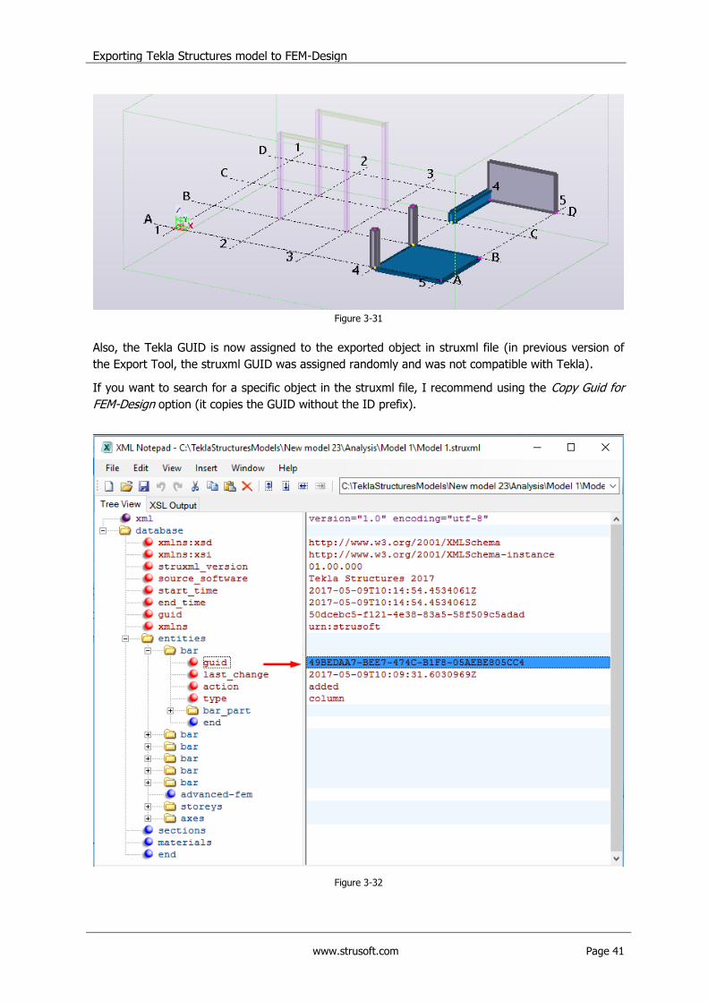
Figure 3-31
Also, the Tekla GUID is now assigned to the exported object in struxml file (in previous version of
the Export Tool, the struxml GUID was assigned randomly and was not compatible with Tekla).
If you want to search for a specific object in the struxml file, I recommend using the Copy Guid for
FEM-Design option (it copies the GUID without the ID prefix).
Figure 3-32
Exporting Tekla Structures model to FEM-Design
www.strusoft.com Page 42
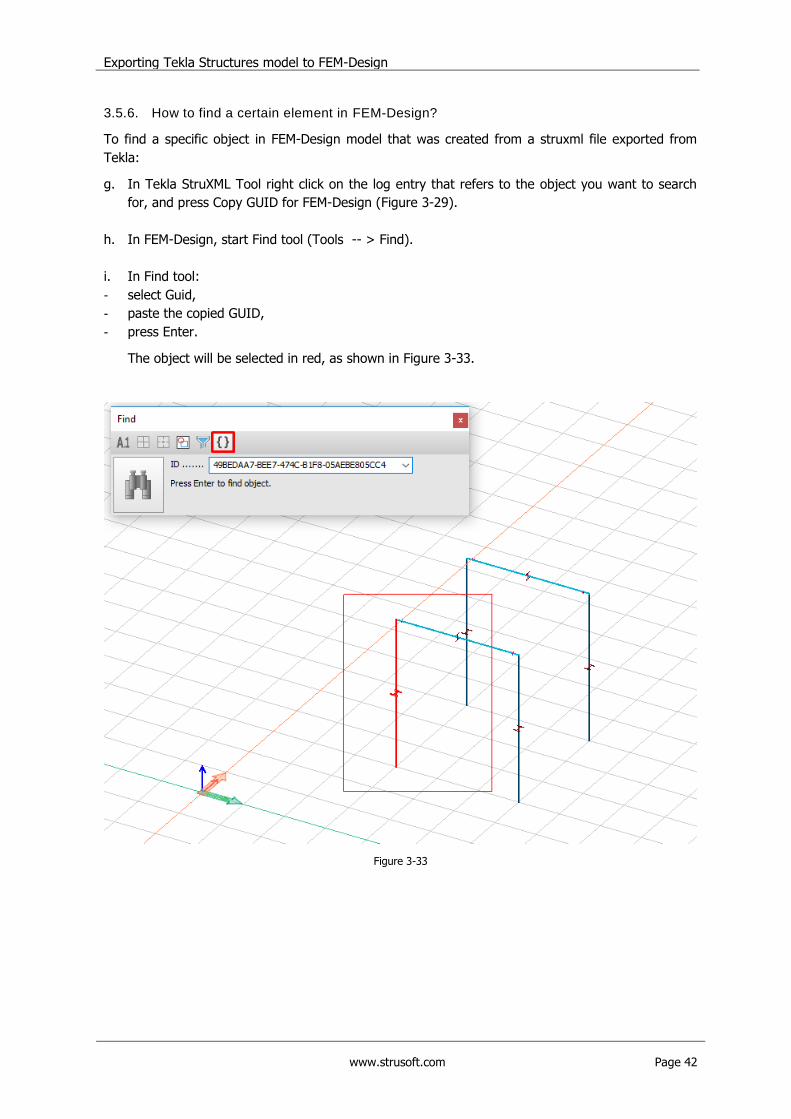
3.5.6. How to find a certain element in FEM-Design?
To find a specific object in FEM-Design model that was created from a struxml file exported from
Tekla:
g. In Tekla StruXML Tool right click on the log entry that refers to the object you want to search
for, and press Copy GUID for FEM-Design (Figure 3-29).
h. In FEM-Design, start Find tool (Tools -- > Find).
i. In Find tool:
- select Guid,
- paste the copied GUID,
- press Enter.
The object will be selected in red, as shown in Figure 3-33.
Figure 3-33