tekmar 3100 purge and trap concentrator 3100 purge and tra… · tekmar 3100 purge and trap...
TRANSCRIPT


TEKMAR 3100
PURGE AND TRAP CONCENTRATOR
User Manual

Copyright© 1998-1999 Tekmar Company
No part of this booklet may be copied, reproduced, transmitted in any form or by any meanselectronic or mechanical, including photocopying, recording, or information storage and retrievalsystems, for any purpose other than the purchaser’s personal use, without the express writtenpermission of Tekmar Company.
UpdatesTekmar-Dohrmann may update the information contained in this booklet without notice to thepurchaser.
The following are registered items:Teflon® is a registered trademark of E.I. du Pont de Nemours & Co.Microsoft® Windows® is a registered trademark of Microsoft, Inc.Swagelok® is a registered trademark of Swagelok CompaniesPulpdent® Snoop is a registered trademark of Pulpdent Corporation
Patents are pending on the Tekmar 3100 Purge and Trap Concentrator.
7143 East Kemper Road, Cincinnati, Ohio 45249(800) 543-4461 • Outside the U.S. and Canada (513) 247-7000 • Service (800) 874-2004
Fax (513) 247-7050 • www.tekmar.comv. 12.20.98 • Revision A • Document Part Number: 14-3100-074

TABLE OF CONTENTS

Tekmar 3100 Purge and Trap Concentrator User Manual
Table of Contents
Chapter 1Introduction
1.1 Overview1.2 Product Description1.3 Concentrator Functions1.4 System Configurations1.4.1 Tekmar 3100 with Cryofocusing Module1.5 Specifications for the 31001.6 Safety Precautions1.6.1 Electrical1.6.2 Temperature1.6.3 Delivery Pressure1.6.4 Miscellaneous
Chapter 2Getting Started
2.1 Overview
2.2 Getting Ready for Installation2.2.1 Operating Environment2.2.2 Power Requirements2.2.3 Gas Supply Requirements
2.3 Unpacking the Concentrator
2.4 Major Components2.4.1 Hand-held Controller2.4.2 Front Panel Display2.4.3 Front Panel Glassware2.4.4 Concentrator Trap2.4.5 Electronic Components
2.5 Gas Inlets and Outlets2.5.1 Sample/Purge Gas Inlet2.5.2 Carrier Gas Inlet

Tekmar 3100 Purge and Trap Concentrator User Manual
Table of Contents
2.6 3100 Valves and Lines
2.7 Autosamplers
2.8 Cryofocusing Module
2.9 TURBOCool
2.10 TekLink
Chapter 33100 Setup
3.1 Overview
3.2 Making Pneumatic Connections3.2.1 Connecting the Sample Gas Line3.2.2 Connecting to the GC and Carrier Gas Supply3.2.2.1 Using GC Regulated Carrier Gas3.2.2.2 Making a Direct Column Connection Using an External Regulator
Assembly
3.3 Setting Sample Pressure
3.4 Setting Trap Pressure Control (TPC)
3.5 Setting Sample Gas Flow
3.6 Installing the Drain Tubing
3.7 Making Electronic Connections3.7.1 Installing Logic Cards3.7.2 Connecting to Accessories (Electronically)3.7.3 Connecting to the GC (Electronically)
3.8 Leak Checking Guidelines3.8.1 Leak Checking

Tekmar 3100 Purge and Trap Concentrator User Manual
Table of Contents
Chapter 4Understanding Operating Steps
4.1 Overview
4.2 Steps in an Operating Sequence
4.3 Operating Cycle Time
4.4 Operating Step Parameters4.4.1 Valve Settings4.4.1.1 Sample Valve4.4.1.2 Bypass Valve4.4.1.3 Drain Valve4.4.1.4 HRP Valve4.4.1.5 Vent Valve4.4.1.6 Backflush Valve4.4.1.7 Six-Port Valve4.4.1.8 Trap Pressure Control Valve4.4.2 Time and Temperature Parameters
4.5 Understanding Operating Steps4.5.1 Purge Ready4.5.2 GC Synchronize4.5.3 Sample Fill4.5.4 TURBO Cooldown4.5.5 Prepurge and Preheat4.5.6 Purge4.5.7 Dry Purge4.5.8 MCS Cooldown4.5.9 Desorb Ready4.5.10 Cryofocusing Module Cooldown4.5.11 Desorb Preheat4.5.12 Desorb 4.5.13 Desorb with Drain 4.5.14 Cryofocusing Inject4.5.15 Bake
Tekmar 3100 Purge and Trap Concentrator User Manual
Table of Contents
Chapter 5Using TekLink to Process Samples
5.1 Installing TekLink 5.1.1 System Requirements5.1.2 Making a Backup Copy of the Installation Disk5.1.3 To Install TekLink5.1.4 To Start TekLink
5.2 Configuring the Concentrator with TekLink5.2.1 Flash Upgrading the 3100 ROM5.2.1.1 Performing the Flash Upgrade5.2.2 TekLink Control Screen5.2.3 Configuring COM Ports5.2.3.1 To Link Each Concentrator With a COM Port5.2.3.2 To Correct the RS232 Error Message During COM Port Setup5.2.4 Designating an Active Concentrator5.2.4.1 To Designate an Active Concentrator5.2.5 Specifying Concentrator Configurations5.2.5.1 All A/C Outputs5.2.5.2 Standby Flow5.2.5.3 Trap Region Type5.2.5.4 GC Handshaking5.2.5.5 GC Type5.2.5.6 User GC Type5.2.5.7 Self-Test Time5.2.5.8 Manual Drain Mode5.2.5.9 Leak Check Mode5.2.5.10 Feed Pressurize Mode
5.3 Using Methods5.3.1 Understanding the Method Editor Screen5.3.1.1 Default 3100 Method Parameter Values5.3.2. Method Editor File Menu5.3.2.1 Load Method From Disk5.3.2.2 Save Method to Disk5.3.2.3 Save Method As...5.3.2.4 Print Method From Disk5.3.2.5 Delete Method From Disk5.3.2.6 Exit Method Editor5.3.3 Method Parameter Values5.3.4 Notes Text Box5.3.5 Min/Max Field5.3.5.1 Method Parameter Value Out of Range Error
Tekmar 3100 Purge and Trap Concentrator User Manual
Table of Contents
5.4 Defining a Method Schedule5.4.1 Understanding the Schedule Control Screen5.4.1.1 Start and Stop Fields5.4.1.2 Method Display Field and Method Selection Button5.4.1.3 RPS (Runs Per Sample) Field5.4.1.4 Min/Max Field5.4.1.5 Load Schedule Button5.4.1.6 Save Schedule Button5.4.1.7 Print Schedule Button5.4.1.8 Delete Schedule Line Button5.4.1.9 Send Schedule Button5.4.1.10 OK Schedule Button5.4.1.11 Schedule Control Help Button5.4.2 Scheduling Runs5.4.2.1 Entering a Method Schedule5.4.2.2 Temperature Zone Status
5.5 Running Samples5.5.1 Overview of the Control Buttons5.5.2 To Initiate a Run5.5.3 Changing the Normal Operating Sequence During a Sample Run 5.5.3.1 Step5.5.3.2 Hold5.5.3.3 Auto5.5.3.4 To Step to Standby5.5.3.5 To Step to Bake5.5.3.6 To Reset the Concentrator5.5.4 Aborting a Schedule and/or Sample5.5.4.1 Abort Entire Schedule5.5.4.2 Abort Current Sample5.5.4.3 Rerun Sample5.5.4.4 Complete Sample and Abort
Tekmar 3100 Purge and Trap Concentrator User Manual
Table of Contents
5.6 TekLink Error Messages5.6.1 Maximum Failsafe Exceeded on Heater X*5.6.2 Minimum Failsafe Exceeded on Heater X5.6.3 Open Thermocouple on Heater X5.6.4 Out-of-Range Error While Scheduling5.6.5 Power Fail5.6.6 Sample Method Does Not Match Schedule Position5.6.7 Self-Test Failure on Heater X5.6.8 System Reset5.6.9 Setpoint Not Reached on Heater X5.6.10 AQUATek ASM Not Responding5.6.11 AQUATek Sensor Error5.6.12 AQUATek Heater Error
Chapter 6Using the Hand-Held Controller to Process Samples
6.1 Overview
6.2 Using the Hand-Held Controller6.2.1 Installing the Hand-held Controller6.2.2 Variable Function Keys6.2.3 Control Keys6.2.3.1 Action Keys6.2.3.2 Screen Keys6.2.3.3 Special Keys6.2.4 Numeric Keys
6.3 Using Screens6.3.1 Front Panel Status Display6.3.1.1 Temperature Parameter Display6.3.1.2 Time Parameter Display6.3.2 Status Screens6.3.2.1 Displaying Operating Status Screens6.3.2.2 Reading the Fields6.3.3 Menu Screens6.3.4 Action Screens6.3.5 Data Entry Screens6.3.5.1 Option Selection Fields6.3.5.2 Data Entry Fields
Tekmar 3100 Purge and Trap Concentrator User Manual
Table of Contents
6.4 Getting Started6.4.1 Performing Self Tests6.4.2 Exiting the Self Tests6.4.3 Clearing a Self Test Error6.4.4 Setting the Date and Time6.4.5 Checking the Unit Type and ROM Version
6.5 Configuring the 31006.5.1 Specify the GC Port Type6.5.2 Specify Handshaking6.5.3 Specify Gas Flows6.5.4 Specify Installed Options
6.6 Understanding Default Methods
6.7 Creating Custom Methods6.7.1 Select a Method6.7.2 Indicate the System Configuration6.7.3 Copy an Existing Method
6.8 Editing 3100 Methods6.8.1 Using the Editing Screens6.8.2 Selecting Parameters
6.9 Moisture Control System (MCS) Parameters
6.10 Restoring Default Parameters
6.11 Creating a New Schedule 6.11.1 Establishing a Method Schedule6.11.2 Entering Schedule Parameters 6.11.2.1 Review Default Schedule Parameters6.11.2.2 Changing the Schedule6.11.2.3 Sample Schedules6.11.3 Running the Schedule6.11.4 Changing the Schedule During a Run6.11.5 Restoring the Default Schedule

Tekmar 3100 Purge and Trap Concentrator User Manual
Table of Contents
6.12 Running a Sample6.12.1 Purge Ready6.12.2 Purge6.12.3 MCS Cooldown6.12.4 Desorb Ready6.12.5 Desorb Preheat6.12.6 Desorb6.12.7 Bake
6.13 Making Subsequent Runs
6.14 Controlling Manual Operations6.14.1 Manual Drain6.14.2 Feed Pressure Setting
6.15 Interrupting a Run6.15.1 Change the Normal Step Sequence6.15.2 Reset the Schedule6.15.3 Review Current Status
6.16 Reviewing Temperature
Chapter 7Maintaining the 3100
7.1 Overview
7.2 Using Standards7.2.1 Prepare Blank Water7.2.2 Prepare the Methanol Standard7.2.3 Prepare the Aqueous Standard
7.3 Preparing Samples7.3.1 Select a Sample Size7.3.2 Load a Sample
7.4 Working with Traps7.4.1 Information on Traps and Adsorbents7.4.2 How to Change a Trap7.4.3 When to Replace a Trap7.4.4 Conditioning a Trap
Tekmar 3100 Purge and Trap Concentrator User Manual
Table of Contents
7.5 Cleaning Sample Lines
7.6 Cleaning Glassware
7.7 Cleaning thE Sample Needle
Chapter 8Using TURBOCool with the 3100
8.1 Overview
8.2 Description
8.3 Applications
8.4 Specifications and Safety
8.5 TURBOCool and Operating Cycle Times
8.6 TURBOCool Method Parameters
8.7 Ordering Parts or Obtaining Service
Chapter 9Troubleshooting the 3100
9.1 Overview
9.2 Calling Tekmar-Dohrmann
9.3 Safety
Tekmar 3100 Purge and Trap Concentrator User Manual
Table of Contents
Chapter 10Service and Parts
10.1 Calling Sales or Service
10.2 3100 Parts List10.2.1 Glassware10.2.2 Sample Handling10.2.3 Syringes10.2.4 Traps10.2.5 Tubing10.2.6 Fittings10.2.7 Heaters 10.2.8 Valves and Pneumatics10.2.9 Electronics10.2.10 Low Volume Inserts10.2.11 Septum Needle Adapters10.2.12 Septum Nuts10.2.13 Interface Cables10.2.14 Miscellaneous
Index

INTRODUCTION
Chapter 1

Tekmar 3100 Purge and Trap Concentrator User Manual 1 -1
Introduction 11.1 Overview
1.2 ProductDescription
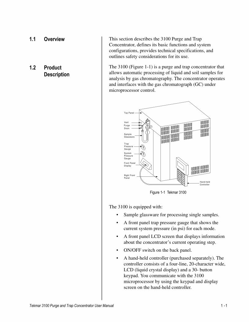
Figure 1-1 Tekmar 3100
This section describes the 3100 Purge and TrapConcentrator, defines its basic functions and systemconfigurations, provides technical specifications, andoutlines safety considerations for its use.
The 3100 is equipped with:
• Sample glassware for processing single samples.
• A front panel trap pressure gauge that shows thecurrent system pressure (in psi) for each mode.
• A front panel LCD screen that displays informationabout the concentrator’s current operating step.
• ON/OFF switch on the back panel.
• A hand-held controller (purchased separately). Thecontroller consists of a four-line, 20-character wide,LCD (liquid crystal display) and a 30- buttonkeypad. You communicate with the 3100microprocessor by using the keypad and displayscreen on the hand-held controller.
Hand-heldControl ler
SampleGlassware
Top Panel
VentPurgeDrain
TrapPressureGauge
SystemPressureGauge
Front PanelDisplay
Right FrontPanel
The 3100 (Figure 1-1) is a purge and trap concentrator thatallows automatic processing of liquid and soil samples foranalysis by gas chromatography. The concentrator operatesand interfaces with the gas chromatograph (GC) undermicroprocessor control.

1 -2 Tekmar 3100 Purge and Trap Concentrator User Manual
Introduction1The 3100 purges volatile organic compounds from water orsoil onto a sorbent trap. The trap is then rapidly heated; theanalytes are swept with GC carrier gas onto the column forseparation and detection, as shown in Figure 1-2.
Figure 1-2 3100 Functions
1.3 ConcentratorFunctions
The liquid sample to beanalyzed is loaded into thefront panel glassware on the3100. A trap inside theconcentrator is packed withan appropriate adsorbentand maintained at ambienttemperature.
The liquid sample isswept with purge gas torelease analytes fromthe sample and depositthem on theconcentrator trap.
������
Concentrator trap
Purge gas
Sample glassware
Analytes are carried awayand deposited on the trap.
���
Purge gas flowsthrough the glassware
��
to theGC
Trap is
backflushed
with carrier gas
The concentrated analyteson the trap are rapidlyheated. The heated trap isthen backflushed with gas todeliver a tight band oforganic analytes to the gaschromatograph.
Tekmar 3100 Purge and Trap Concentrator User Manual 1 -3
Introduction 11.4 System
ConfigurationsThe 3100 concentrator processes a single sample anddelivers the resulting analytes to a gas chromatograph.You may also use the 3100 with other Tekmar-Dohrmannaccessories which can extend and enhance 3100 functions.Please refer to the appropriate user manuals for furtherinformation.
1.4.1 Tekmar 3100 withCryofocusing Module
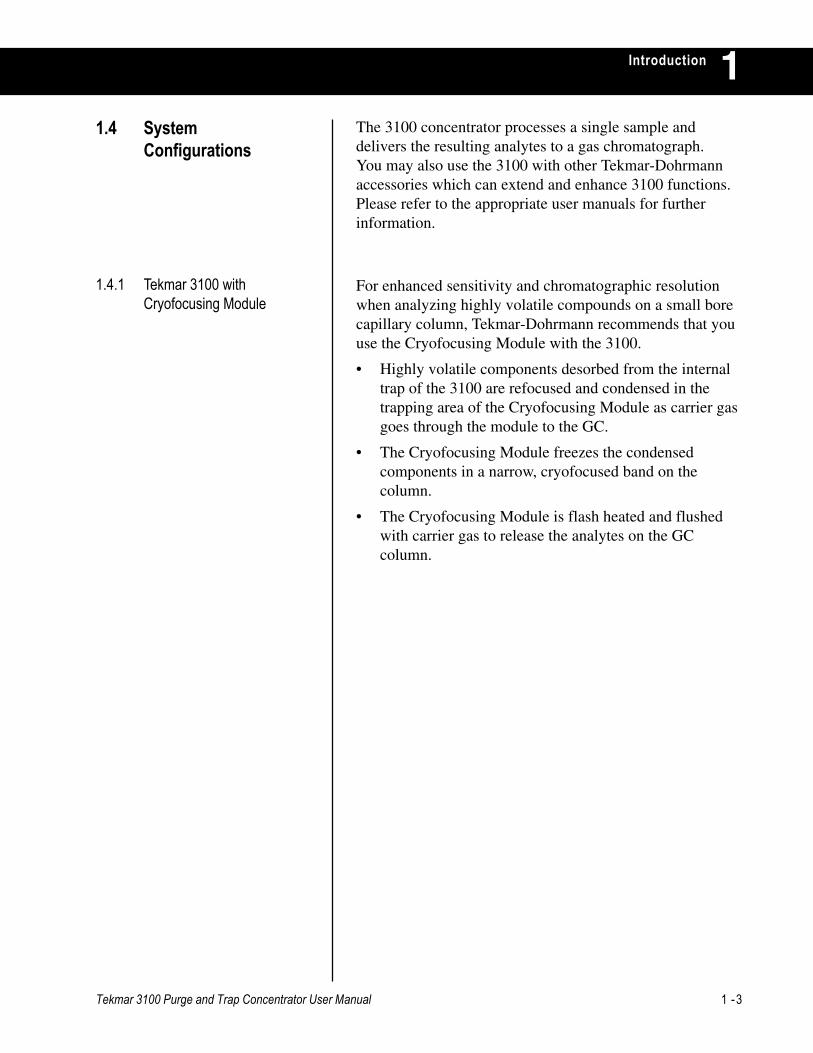
For enhanced sensitivity and chromatographic resolutionwhen analyzing highly volatile compounds on a small borecapillary column, Tekmar-Dohrmann recommends that youuse the Cryofocusing Module with the 3100.
• Highly volatile components desorbed from the internaltrap of the 3100 are refocused and condensed in thetrapping area of the Cryofocusing Module as carrier gasgoes through the module to the GC.
• The Cryofocusing Module freezes the condensedcomponents in a narrow, cryofocused band on thecolumn.
• The Cryofocusing Module is flash heated and flushedwith carrier gas to release the analytes on the GCcolumn.
1 -4 Tekmar 3100 Purge and Trap Concentrator User Manual
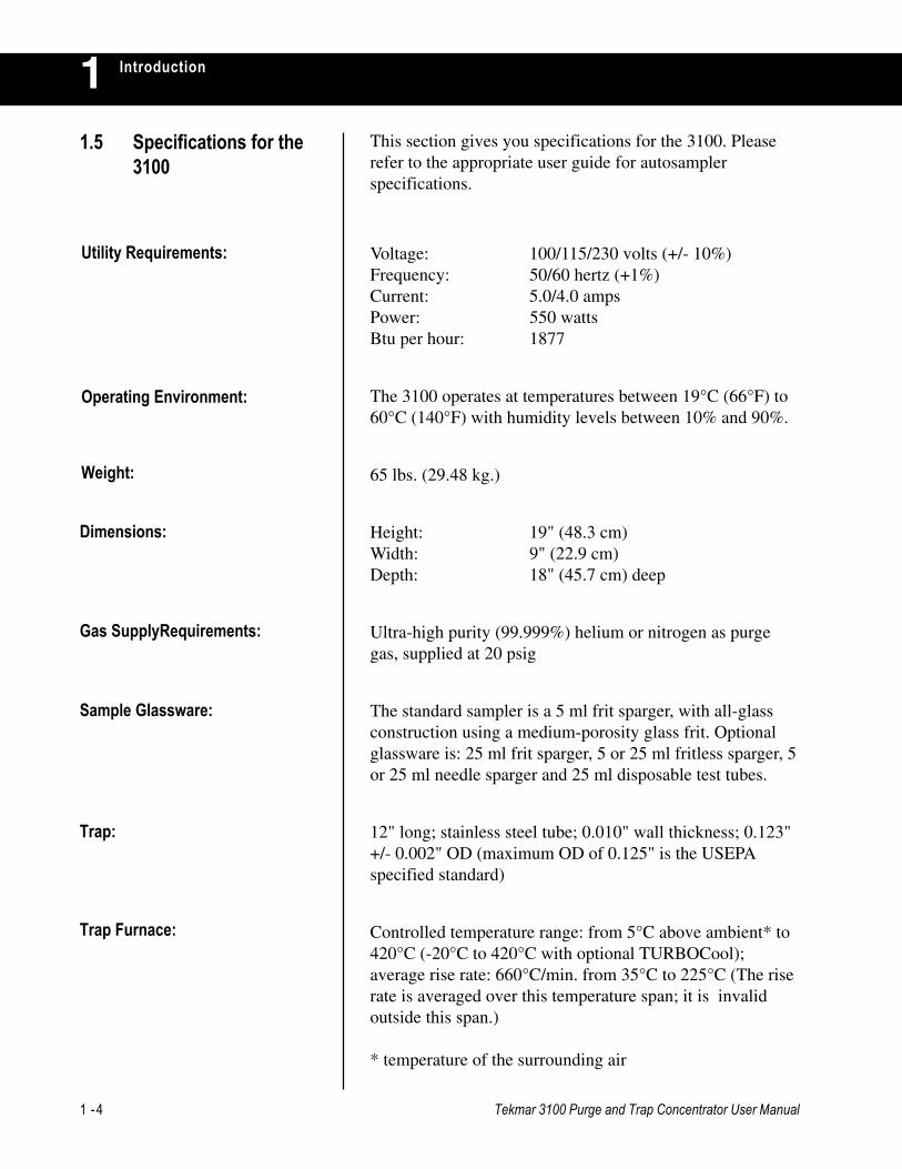
Introduction1This section gives you specifications for the 3100. Pleaserefer to the appropriate user guide for autosamplerspecifications.
Voltage: 100/115/230 volts (+/- 10%)Frequency: 50/60 hertz (+1%)Current: 5.0/4.0 ampsPower: 550 wattsBtu per hour: 1877
The 3100 operates at temperatures between 19°C (66°F) to60°C (140°F) with humidity levels between 10% and 90%.
65 lbs. (29.48 kg.)
Height: 19" (48.3 cm)Width: 9" (22.9 cm)Depth: 18" (45.7 cm) deep
Ultra-high purity (99.999%) helium or nitrogen as purgegas, supplied at 20 psig
The standard sampler is a 5 ml frit sparger, with all-glassconstruction using a medium-porosity glass frit. Optionalglassware is: 25 ml frit sparger, 5 or 25 ml fritless sparger, 5or 25 ml needle sparger and 25 ml disposable test tubes.
12" long; stainless steel tube; 0.010" wall thickness; 0.123"+/- 0.002" OD (maximum OD of 0.125" is the USEPAspecified standard)
Controlled temperature range: from 5°C above ambient* to420°C (-20°C to 420°C with optional TURBOCool);average rise rate: 660°C/min. from 35°C to 225°C (The riserate is averaged over this temperature span; it is invalidoutside this span.)
* temperature of the surrounding air
1.5 Specifications for the3100
Utility Requirements:
Operating Environment:
Weight:
Dimensions:
Gas SupplyRequirements:
Sample Glassware:
Trap:
Trap Furnace:

Tekmar 3100 Purge and Trap Concentrator User Manual 1 -5
Introduction 1Variable; set at the factory to maintain a recommended backpressure of 4 psi; flow rate: 35 ml/min.
• A 115 VAC motor-actuated, 6-port switching valve withremovable rotor; temperature controlled from ambientto 300°C
• 12 VDC solenoid-actuated, 2 and 3-port sample, bypass,high rate purge (HRP), drain and vent valves
• Flow Tuned Tubing (FTT)TM features constant uniforminternal diameters on all fittings, valves and tubing;eliminates dead volume and maintains a constant linearvelocity during desorption to the gas chromatograph
• Transfer line, 72" total length - 60" outside of unit;heated, variable: ambient to 300°C
• Optional sample pocket and tube heaters; variable: fromambient to 100°C
• 3100 concentrator: 0.1% after 1000 ng standard
There is no difference between carryover amounts using U-shaped glassware versus needle sparger glassware (with orwithout drain).
Calibration range: 0.5 ng to 2000 ngSystem range: low ppt to 10 ppm
When using a Cryofocusing Module: Approximately 1 literto cool the cryofocus trap to -120°C. Then 1/4 liter perminute once the cooldown temperature is reached (totaltime for Desorb Preheat and Desorb modes.)
Removes moisture from the gas stream going to the GC;operating temperature: 5°C above ambient to 400°C
Microprocessor - Motorola 68000, running at 12 MHzCPU memory - 128K ROM; 64K RAM (expandable to128K)
9600
Sample Path:
Valving:
Trap Pressure ControlTM:
Baud Rate:
Carryover Specifications:
Operating Range ofConcentration:
LN2 Consumption:
Moisture Control System:
Electronic Control:

1 -6 Tekmar 3100 Purge and Trap Concentrator User Manual
Introduction1The 3100 accepts parameter values that you enter by way ofan RS232C serial interface. To enter the parameter values,use one of the following:• A hand-held controller connected directly to an I/O port• A personal computer with optional TekLink software.
To use TekLink, you must have the following:1. 80386 or greater computer running Microsoft®
WindowsTM version 3.1 or later2. Any kind of DOS (version 5.0 or greater)3. Hard drive with at least 2 MB (two megabytes) of
free space4. 4 MB of RAM (8 MB recommended)5. Disk drive that reads 3 1/2" 1.44MB diskettes6. At least one free serial port for connection to the
3100
The 3100 uses a two-line, 20 character-wide LCD screen onthe front panel and a four-line, 20-character display on thehand-held controller.
The 3100 has four expansion slots on the Mother Board foraccessory interfaces.
During operation, the 3100 sends and receives thefollowing signals:• Begin/End Desorb output signal• Start GC/MS and Data System output signal• Desorb Ready output signal• GC Ready/Continue input signal• Purge Permission input signal• Purge Ready output signal
The 3100 works with almost all commercially-available GCinstruments. It supplies or accepts GC and Data Systemstart and ready signals by way of a software-selectable GCI/O board.
All commercially-available columns. Systems withcolumns that have an I.D. of less than 0.53 mm may requirethe Cryofocusing Module, depending on the systems'configurations.
Up to 16 methods.
Up to 12 method changes in any sample order on a singleautomatic cycle with a Tekmar-Dohrmann autosampler
I/O Signals:
GC Interface:
Column Capability:
Method Storage:
Expansion Capability:
Data Display:
Data Input:
Method Scheduling:
Tekmar 3100 Purge and Trap Concentrator User Manual 1 -7
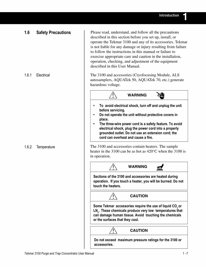
Introduction 1Please read, understand, and follow all the precautionsdescribed in this section before you set up, install, oroperate the Tekmar 3100 and any of its accessories. Tekmaris not liable for any damage or injury resulting from failureto follow the instructions in this manual or failure toexercise appropriate care and caution in the installation,operation, checking, and adjustment of the equipmentdescribed in this User Manual.
1.6 Safety Precautions
1.6.1 Electrical
1.6.2 Temperature The 3100 and accessories contain heaters. The sampleheater in the 3100 can be as hot as 420°C when the 3100 isin operation.
WARNING
• To avoid electrical shock, turn off and unplug the unitbefore servicing.
• Do not operate the unit without protective covers inplace.
• The three-wire power cord is a safety feature. To avoidelectrical shock, plug the power cord into a properlygrounded outlet. Do not use an extension cord; thecord can overheat and cause a fire.
WARNING
Sections of the 3100 and accessories are heated duringoperation. If you touch a heater, you will be burned. Do nottouch the heaters.
CAUTION
Some Tekmar accessories require the use of liquid CO2 orLN2 . These chemicals produce very low temperatures thatcan damage human tissue. Avoid touching the chemicalsor the surfaces that they cool.
CAUTION
Do not exceed maximum pressure ratings for the 3100 oraccessories.
The 3100 and accessories (Cryofocusing Module, ALSautosamplers, AQUATek 50, AQUATek 70, etc.) generatehazardous voltage.

1 -8 Tekmar 3100 Purge and Trap Concentrator User Manual
Introduction1The Cryofocusing Module uses liquid nitrogen coolant.1.6.3 Delivery Pressure
1.6.4 Miscellaneous
CAUTION
If coolant delivery pressure exceeds 75 psig, a relief valve onthe cryogenic valve assembly will vent the excess pressure.
WARNING
TURBOCool requires a SUPPLY of high pressure liquid C02.Do not allow the SUPPLY pressure to exceed 1000 psi.
WARNING
To avoid any type of interference with the 3100 operation,maintain at least two inches of unobstructed space aroundthe 3100. Move all other equipment outside the two-inchperimeter. The 3100 requires a clear surface area of at least20" (51cm) deep and 15" (38 cm) wide, with no shelves oroverhanging obstructions above. The surfacemust be able to support at least 40 pounds.
CAUTION
Keep the 3100 away from corrosive gasses, liquids or solids.Corrosive substances will damage outside surfaces and theparts inside.
Operate TURBOCool in a well ventilated area to preventsaturation of the ambient air with carbon dioxide.
CAUTION

GETTING STARTED
Chapter 2

Tekmar 3100 Purge and Trap Concentrator User Manual 2 -1
Getting Started 22.1 Overview This section describes:
• The prerequisites and site preparation for a 3100installation.
• Unpacking and checking your 3100 shipment.
• The major components of the 3100.
Equipment installation and operation will be easier if youuse the illustrations to identify and locate the describedcomponents on the 3100.
Please read the instructions in this section before you beginto install the 3100. If you have any questions about siterequirements for installing and operating the 3100, pleasecall the Tekmar-Dohrmann Service Department at (800)874-2004.
The 3100 operates at temperatures between 19°C to 60°Cwith humidity levels between 10% and 90%. Generallyspeaking, an environment with temperature and humiditythat are reasonably constant and comfortable for an operatoris an environment in which the concentrator will performreliably.
2.2 Getting Ready forInstallation
2.2.1 Operating Environment
The 3100 requires a clear surface area at least 18" (46 cm)deep and 15" (38 cm) wide, with no shelves or overhangingobstructions above. The surface must be able to support atleast 40 pounds.
CAUTION
Keep the concentrator away from corrosive substances -gas,liquid, or solid - to avoid material and/or component damage.
To avoid any type of interference with 3100 operation,maintain at least two inches of unobstructed space aroundthe unit. Move all otherequipment outside the two-inchperimeter.
WARNING
2 -2 Tekmar 3100 Purge and Trap Concentrator User Manual
Getting Started2
2.2.3 Gas Supply Requirements Concentrator operation requires the availability of ultra-high purity helium (as purge gas). Check the followingitems:
1. Helium purity must be 99.999%, 0.5% hydrocarbontested.
2. Gas pressure at the source must be high enough to:• Allow at least 20 psi pressure drop at every flow or
pressure regulator.• Travel the distance from the source to the
concentrator.• Provide the required gas pressure at the
concentrator. Operation of the 3100 requires heliumat an incoming (supply) pressure of 20 to 60 psig.
3. Gas supply tubing diameter depends on the maximumpressure drop allowable for your setup. If the heliumsupply is close to the concentrator, you may use 1
8 "diameter tubing. However, you may want to use largerdiameter supply lines, typically ¼", to reduce pressuredrop under the following circumstances:• The gas supply is a long way from the concentrator.• A single source supplies several instruments.• A single source will be subjected to high demand
for gas.4. Gas supply tubing lengths must be adequate. Be
generous when cutting lengths of tubing for localsupply lines; a relatively long coil of tubing between thesupply and the 3100 allows you to move the instrument(to reach rear cover panels, for example) withoutdisconnecting the plumbing.
5. Gas line fittings and regulators must be the correct sizeand type. Consult your local gas supplier for type andsize of cylinder valves; then select compatible pressureregulators based on the required valves. Keep theseconsiderations in mind:
After selecting and clearing a location for the concentrator,check the availability of the required grounded outlets. The3100 uses 115V/230V (± 10% ) power at 50/60 (±1%) Hz,with one grounded, three-pronged receptacle for the mainpower cord. Each additional accessory you plan to use mayalso require one or more grounded outlets.
2.2.2 Power Requirements
Tekmar 3100 Purge and Trap Concentrator User Manual 2 -3
Getting Started 2
Please read the instructions in this section before you beginto set up the 3100. If you have any questions about the setup, please call the Tekmar-Dohrmann Service Departmentat (800) 874-2004.
2.3 Unpacking theConcentrator
1. Remove the 3100 kit box and the concentrator from theshipping carton. Each concentrator is shipped with a kitbox. An optional installation kit with additional partsneeded to set up and install the 3100 is available fromTekmar-Dohrmann (P/N 14-5092-100).
2. Compare the contents of the kit box and/or installationkit against the packing list that accompanies yourshipment. Check for each listed item. • If an item is missing, call the Tekmar-Dohrmann
Customer Service Department toll-free at (800) 543-4461; outside the US and Canada, call (513) 247-7000.
• If any shipped item is damaged, immediately notifythe shipping carrier and the Tekmar-DohrmannCustomer Service Department of its condition.
Failure to follow these instructions may void your warranty forcomponents damaged in shipment.
CAUTION
Always use instrument-grade Teflon® tape to seal threadconnections. Do not use pipe dope or lower grades ofTeflon® tape; volatile materials in the dope and/or low-grade tape will contaminate the tubing.
CAUTION
• To reduce high source pressures to the pressurerequired by the concentrator, use high-qualitypressure regulators with stainless steel diaphragms.Tekmar-Dohrmann recommends using a single, two-stage regulator, rather than two single-stage pressureregulators to meet the concentrator’s pressurespecification.
• On/off valves, while not essential, are very usefulwhen mounted on the outlet fitting of a two-stageregulator.
• Avoid pipe thread connections in your gas supplylines. If you must use them, seal them withinstrument-grade Teflon® tape.
2 -4 Tekmar 3100 Purge and Trap Concentrator User Manual
Getting Started2
For the safety of everyone concerned, Tekmar-Dohrmann willnot service returned instruments that are shipped withneedles or any other sharp objects installed on their exteriors;Tekmar-Dohrmann will promptly return these instruments tocustomers.
This policy mainly applies to returned purge and trapautosamplers, which are shipped with stainless steel needlesor glass dip tubes installed.
To receive prompt, reliable service, and reduce the risk ofinjury, please remove all sharp objects from the exterior of anyTekmar-Dohrrmann instrument before shipping.
WARNING
3. Examine the concentrator carefully. If it is damaged,notify the shipping carrier and Tekmar-Dohrmannimmediately. Do not continue installation until aTekmar-Dohrmann representative authorizes you to doso.
4. Save all shipping materials until you verify that theinstrument operates correctly.
5. Do not return the concentrator unless authorized to doso by a Tekmar-Dohrmann representative.
Tekmar 3100 Purge and Trap Concentrator User Manual 2 -5
Getting Started 2The 3100 (Figure 1-1) consists of a concentrator with afront-panel sample glassware assembly and an optionalhand-held controller.
2.4 Major Components
2.4.1 Hand-held Controller The hand-held controller is a four-line, 20-character wide,LCD (liquid crystal display) and a keypad. The displayconsists of data entry screens for programming and enteringdata, menu and action screens for selecting options andcommands, and status screens for viewing during operation.
The front-panel display provides status information duringconcentrator operation.• The Trap Pressure gauge shows the current sample gas
pressure (in psig).• The LCD screen displays information about the
concentrator’s current operating step. The first linedisplays the step name, the number of the currentlyactive method (or operating sequence), and the numberfor the position of the currently active sample. Thebottom line displays the current reading for the mostsignificant operating step parameter.
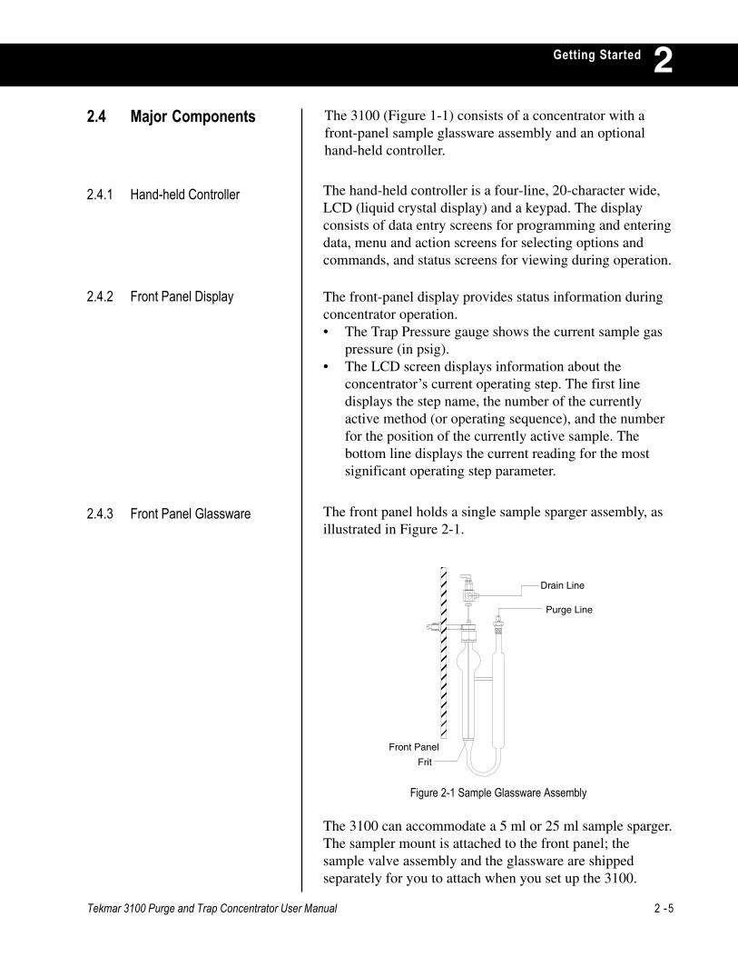
The front panel holds a single sample sparger assembly, asillustrated in Figure 2-1.
���� Drain Line
Purge Line
Front Panel
Frit
Figure 2-1 Sample Glassware Assembly
The 3100 can accommodate a 5 ml or 25 ml sample sparger.The sampler mount is attached to the front panel; thesample valve assembly and the glassware are shippedseparately for you to attach when you set up the 3100.
2.4.2 Front Panel Display
2.4.3 Front Panel Glassware
2 -6 Tekmar 3100 Purge and Trap Concentrator User Manual
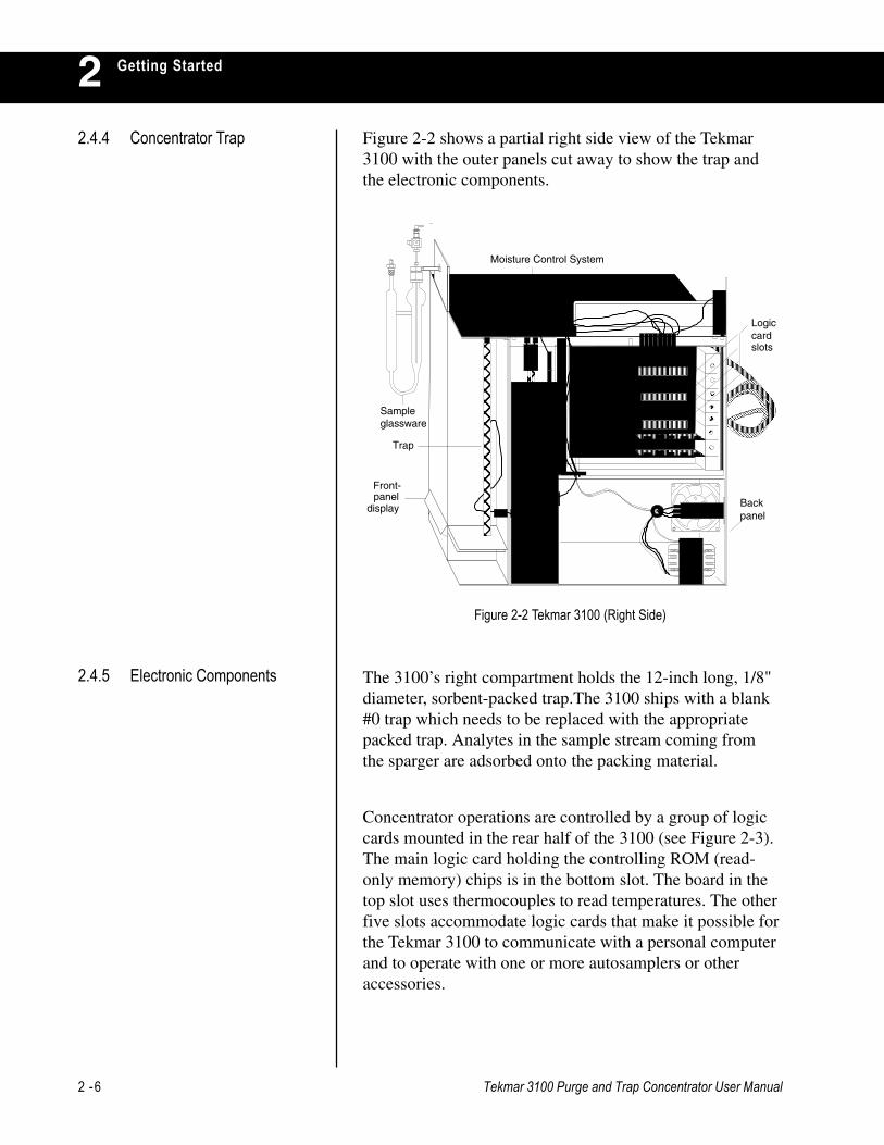
Getting Started2Figure 2-2 shows a partial right side view of the Tekmar3100 with the outer panels cut away to show the trap andthe electronic components.
Figure 2-2 Tekmar 3100 (Right Side)
����
���� ����������
����������
�����������������������������������������������������������������������������������������������
������������������������������������
�������
Front-panel
display
Moisture Control System
Trap
���������������������������������������������������������������������������������
��������������
������
Backpanel
Logiccard slots
����
Sample glassware
The 3100’s right compartment holds the 12-inch long, 1/8"diameter, sorbent-packed trap.The 3100 ships with a blank#0 trap which needs to be replaced with the appropriatepacked trap. Analytes in the sample stream coming fromthe sparger are adsorbed onto the packing material.
Concentrator operations are controlled by a group of logiccards mounted in the rear half of the 3100 (see Figure 2-3).The main logic card holding the controlling ROM (read-only memory) chips is in the bottom slot. The board in thetop slot uses thermocouples to read temperatures. The otherfive slots accommodate logic cards that make it possible forthe Tekmar 3100 to communicate with a personal computerand to operate with one or more autosamplers or otheraccessories.
2.4.4 Concentrator Trap
2.4.5 Electronic Components
Tekmar 3100 Purge and Trap Concentrator User Manual 2 -7
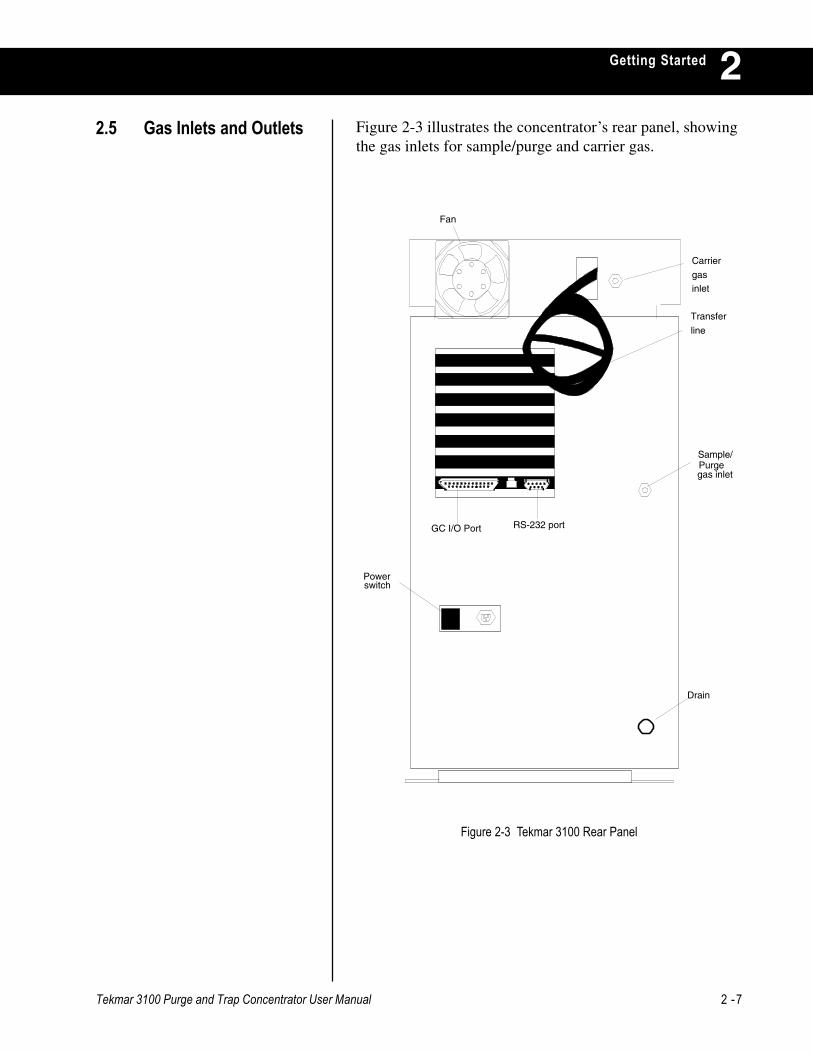
Getting Started 2Figure 2-3 illustrates the concentrator’s rear panel, showingthe gas inlets for sample/purge and carrier gas.
~ O
Carrier
gasinlet
Sample/
gas inlet
Transfer
line
Fan
Powerswitch
Drain
GC I/O Port RS-232 port
Purge
2.5 Gas Inlets and Outlets
Figure 2-3 Tekmar 3100 Rear Panel

2 -8 Tekmar 3100 Purge and Trap Concentrator User Manual
Getting Started2Sample gas (ultra-high purity helium) flows through thesparger to carry organic analytes onto the trap. (Nitrogencan be used as sample gas, but it may contain moreimpurities.) The helium or nitrogen enters the back panel atthe opening labeled “Sample”.
Depending on the concentrator’s operating mode, samplegas flows through the sample sparger (to carry analytes tothe trap), or it bypasses the sparger to circulate in a passivecircuit and flows out the front panel vent.
Tekmar-Dohrmann recommends a sample gas flow of 35ml/min ± 5 ml for 11 minutes to achieve a 385 ml purgevolume.
Carrier gas is high purity helium (or nitrogen) used todesorb volatile analytes off the internal trap and carry themthrough the transfer line back to the GC. Carrier gas entersthe back panel at the opening labeled “Carrier”. Dependingon the concentrator’s current operating mode, carrier gasflows through the trap and carries volatile analytes over tothe GC, or it makes a passive circuit through theconcentrator and returns, unchanged, to the GC through thetransfer line.
The valves visible from the top of the unit are:• Two adjustable regulating valves near the back of the
3100. They control the sample pressure and sampleflow of gas entering the 3100 through the sample gasinlet.
• The sample and bypass valves. Sample gas flows fromthe flow controller to the sample valve. When thesample valve is closed, sample gas flow is cut off. Anopen sample valve directs flow to the bypass valve,which routes it either to the sample sparger or to thesample tee.
• The sample tee accepts flow from the sample sparger orfrom the bypass valve and directs it to the six-portvalve.
• The six-port valve inside the valve oven has twosettings that control the direction of sample and carriergas flow through the concentrator.
• The trap pressure control (TPC) valve controls backpressure on the concentrator trap.
2.6 3100 Valves and Lines
2.5.1 Sample/Purge Gas Inlet
2.5.2 Carrier Gas Inlet

Tekmar 3100 Purge and Trap Concentrator User Manual 2 -9
Getting Started 2• The 3100 can work with the ALS 2016/2032 to process
up to 32 liquid and/or soil samples.
• The 3100 can work with the AQUATek 50 vialautosampler to process up to 50 drinking and wastewatersamples.
• The 3100 can process up to 65 drinking and wastewatersamples with the 2016 and AQUATek 50 (up to 15 on the2016 and up to 50 on the AQUATek 50).
• The 3100 can work with the AEROTrap 6016/6032 toprocess up to 32 air samples.
• The 3100 can process up to 16 air samples (with theAEROTrap 6016) or up to 16 liquid and soil samples(with the AEROTrap 6032 and the ALS 2016).
• The 3100 can process up to 70 liquid samples with theAQUATek 70.
For further instructions, see the manuals shipped with theautosamplers.
If you plan to run samples that contain highly volatilecomponents on a small bore capillary column, Tekmarrecommends using a Cryofocusing Module (available as aseparate purchase) with the 3100. For more information, seethe manual shipped with the Cryofocusing Module.
TURBOCool is an optional accessory to the 3100. TheTURBOCool accessory keeps the trap at a uniformtemperature and permits purging onto a subambient* trap.This minimizes breakthrough and improves resolution of thelighter, early eluting gases in gas chromatography.
* temperature that is lower than the surrounding air
2.7 Autosamplers
2.8 Cryofocusing Module
2.9 TURBOCool
TekLink software makes it possible for you to use apersonal computer (PC) running Microsoft® WindowsTM tomonitor, schedule and control the operation of one, two,three or four concentrators. Using TekLink, you can:
• define custom methods or operating sequences thatmeet your analytical requirements.
• set up schedules for running certain methods atspecified positions on an autosampler.
• start, interrupt and/or reset a run in progress.
2.10 TekLink
2 -10 Tekmar 3100 Purge and Trap Concentrator User Manual
Getting Started2

3100 SETUP
Chapter 3

Tekmar 3100 Purge and Trap Concentrator User Manual 3 -1
3100 Setup 33.1 Overview
3.2 Making PneumaticConnections
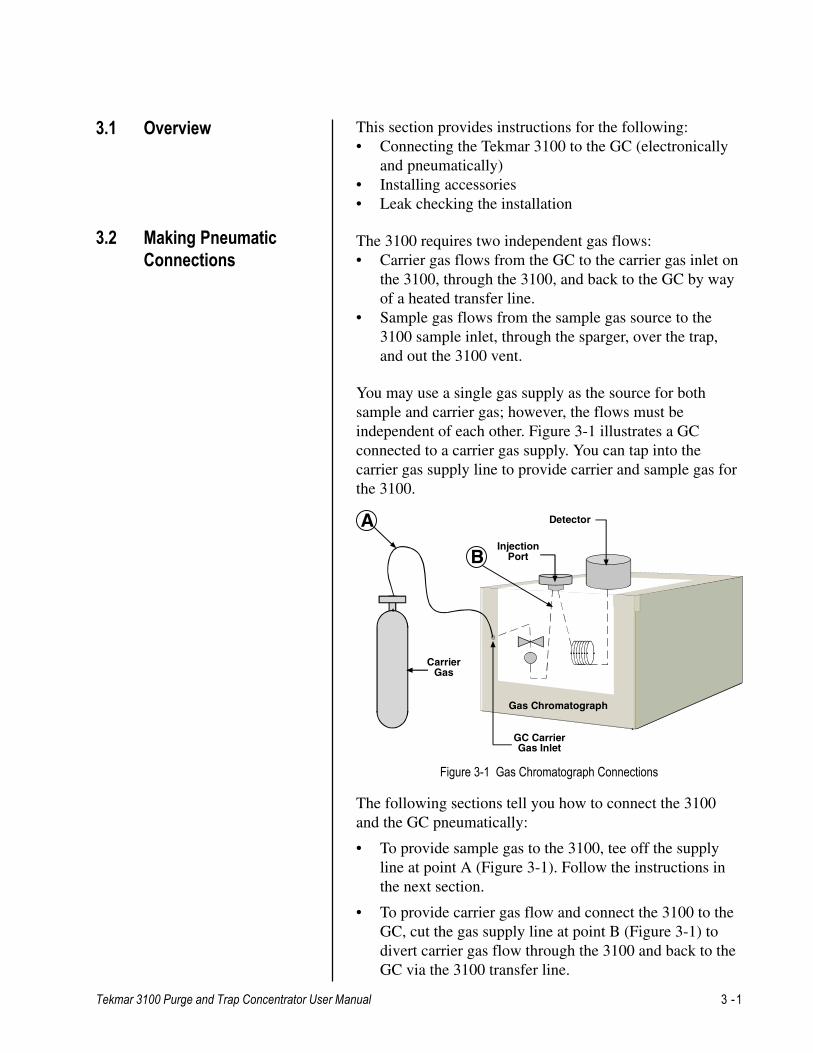
The following sections tell you how to connect the 3100and the GC pneumatically:
• To provide sample gas to the 3100, tee off the supplyline at point A (Figure 3-1). Follow the instructions inthe next section.
• To provide carrier gas flow and connect the 3100 to theGC, cut the gas supply line at point B (Figure 3-1) todivert carrier gas flow through the 3100 and back to theGC via the 3100 transfer line.
This section provides instructions for the following:• Connecting the Tekmar 3100 to the GC (electronically
and pneumatically)• Installing accessories• Leak checking the installation
The 3100 requires two independent gas flows:• Carrier gas flows from the GC to the carrier gas inlet on
the 3100, through the 3100, and back to the GC by wayof a heated transfer line.
• Sample gas flows from the sample gas source to the3100 sample inlet, through the sparger, over the trap,and out the 3100 vent.
You may use a single gas supply as the source for bothsample and carrier gas; however, the flows must beindependent of each other. Figure 3-1 illustrates a GCconnected to a carrier gas supply. You can tap into thecarrier gas supply line to provide carrier and sample gas forthe 3100.
Figure 3-1 Gas Chromatograph Connections
Gas Chromatograph
InjectionPort
Detector
CarrierGas
A
B
GC CarrierGas Inlet
3 -2 Tekmar 3100 Purge and Trap Concentrator User Manual
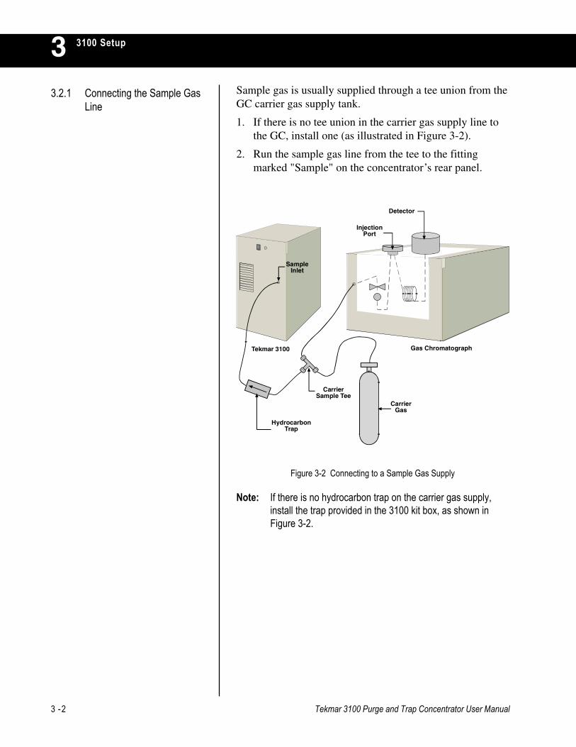
3100 Setup3Sample gas is usually supplied through a tee union from theGC carrier gas supply tank.
1. If there is no tee union in the carrier gas supply line tothe GC, install one (as illustrated in Figure 3-2).
2. Run the sample gas line from the tee to the fittingmarked "Sample" on the concentrator’s rear panel.
3.2.1 Connecting the Sample GasLine
Note: If there is no hydrocarbon trap on the carrier gas supply,install the trap provided in the 3100 kit box, as shown inFigure 3-2.
CarrierGas
CarrierSample Tee
HydrocarbonTrap
SampleInlet
Gas ChromatographTekmar 3100
InjectionPort
Detector
Figure 3-2 Connecting to a Sample Gas Supply
Tekmar 3100 Purge and Trap Concentrator User Manual 3 -3
3100 Setup 33.2.2 Connecting to the GC and
Carrier Gas Supply
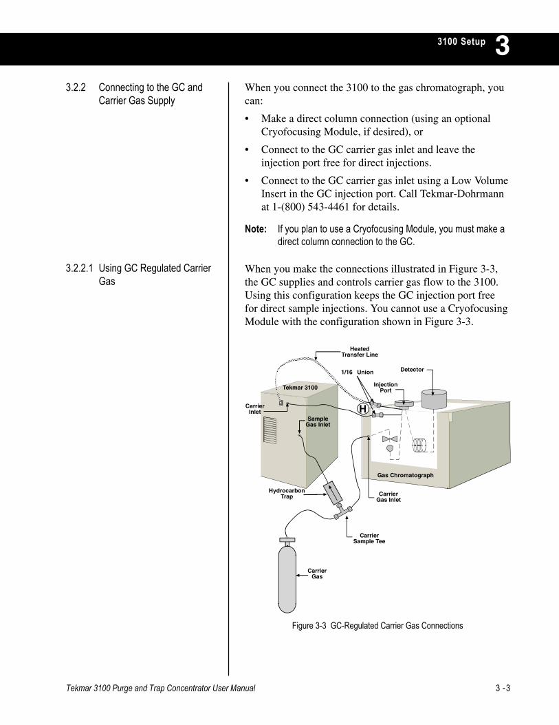
When you make the connections illustrated in Figure 3-3,the GC supplies and controls carrier gas flow to the 3100.Using this configuration keeps the GC injection port freefor direct sample injections. You cannot use a CryofocusingModule with the configuration shown in Figure 3-3.
3.2.2.1 Using GC Regulated CarrierGas
When you connect the 3100 to the gas chromatograph, youcan:
• Make a direct column connection (using an optionalCryofocusing Module, if desired), or
• Connect to the GC carrier gas inlet and leave theinjection port free for direct injections.
• Connect to the GC carrier gas inlet using a Low VolumeInsert in the GC injection port. Call Tekmar-Dohrmannat 1-(800) 543-4461 for details.
Note: If you plan to use a Cryofocusing Module, you must make adirect column connection to the GC.
SampleGas Inlet
Gas Chromatograph
Tekmar 3100 InjectionPort
Detector
CarrierGas
CarrierSample Tee
HydrocarbonTrap
������������������������������������������������������������������������������������
CarrierGas Inlet
HeatedTransfer Line
CarrierInlet
1/16 Union
H
Figure 3-3 GC-Regulated Carrier Gas Connections
3 -4 Tekmar 3100 Purge and Trap Concentrator User Manual
3100 Setup3
3. Open the line at a point one or two inches from theinjector housing (point H in Figure 3-3). If a unionconnects tubing from the carrier gas supply to thestainless steel injector port inlet, disconnect the union.If there is no union, cut the line.
4. Connect the line coming from the GC controlpneumatics to a 1/16" union.
5. Connect a piece of 1/16" nickel tubing to the union;connect the other end to the union labeled "carrier" onthe back of the 3100.
6. Connect the tubing to the injection port inlet (at point Fof Figure 3-4 on the following page) using a 1/16"Swagelok union.
To make the connections:
1. Make sure the GC is not hot; allow it to cool to roomtemperature.
2. Select an injection port. You may have to remove thecovers around the port to expose the stainless steel linewhich supplies carrier gas to the port.
Note: You may need to secure the center of the union to thecolumn cage to relieve any stress caused by the weight ofthe union. If the injection port is split/splitless, you must capthe split vent and septum purge. Some applications requireyou to use the split. If this is the case, the split vent andseptum purge should remain open.
CAUTIONSome injection ports have multiple pieces of tubingconnecting to the injection port. Do not cut any lines unlessyou are sure which is the carrier line.
Tekmar 3100 Purge and Trap Concentrator User Manual 3 -5
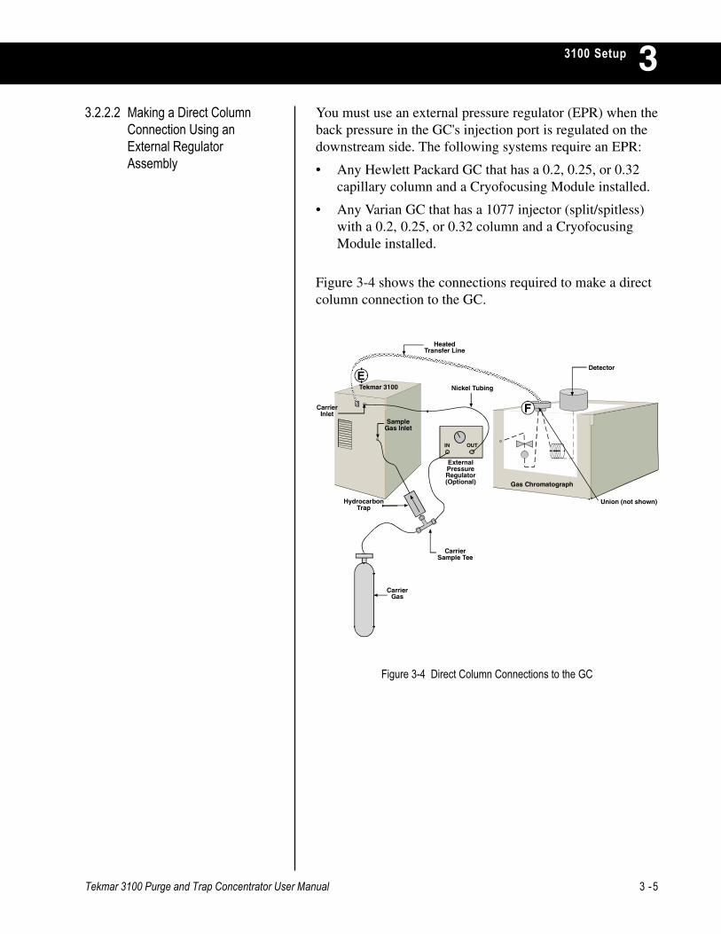
3100 Setup 3You must use an external pressure regulator (EPR) when theback pressure in the GC's injection port is regulated on thedownstream side. The following systems require an EPR:
• Any Hewlett Packard GC that has a 0.2, 0.25, or 0.32capillary column and a Cryofocusing Module installed.
• Any Varian GC that has a 1077 injector (split/spitless)with a 0.2, 0.25, or 0.32 column and a CryofocusingModule installed.
Figure 3-4 shows the connections required to make a directcolumn connection to the GC.
3.2.2.2 Making a Direct ColumnConnection Using anExternal RegulatorAssembly
Figure 3-4 Direct Column Connections to the GC
SampleGas Inlet
Tekmar 3100
CarrierGas
CarrierSample Tee
HydrocarbonTrap
HeatedTransfer Line
CarrierInlet
Gas Chromatograph
Detector
IN OUT
Nickel Tubing
ExternalPressureRegulator(Optional)
Union (not shown)
������������������������������������������������������������������������������������������������������������������������������������
E
F

3 -6 Tekmar 3100 Purge and Trap Concentrator User Manual
3100 Setup3To make a direct column connection:
1. Make sure the GC is not hot; allow it to cool down toroom temperature.
2. Since this configuration removes carrier gas flow fromthe GC pneumatic control, you must install an externalpressure regulator (Tekmar-Dohrmann P/N 14-3938-000, or equal) between the gas supply source and thecarrier gas inlet to the 3100.
• Disconnect the carrier gas line from the GC and runit to the inlet of the external pressure regulator.
• Connect the outlet of the regulator to the carrier gasinlet on the 3100 rear panel at point E (see Figure 3-4).
3. Find an opening in the GC to route the transfer line intothe GC oven to make the connection to the column (i.e.unused injection port or detector).
4. Using a zero dead volume union, connect the column tothe transfer line from the 3100 at point F (see Figure 3-4).
Notes:
1. If you use the Tekmar 3100 with a Cryofocusing Module,connect the transfer line to the Cryofocusing Module, notdirectly to the GC. Please refer to the Cryofocusing ModuleInstruction Manual for installation instructions.
2. Be sure that the line heater assembly on the transfer line isas close to the injection port as possible to minimize coldspots. As an alternative, the transfer line can pass throughthe injection port with the union in the GC oven.
Tekmar 3100 Purge and Trap Concentrator User Manual 3 -7
3100 Setup 31. Turn on the 3100 by pressing the power switch on the
rear panel.
2. Press ENTER to clear the Start-Up screen. The 3100performs self tests and goes to Standby.
3. Make sure that Standby Flow is defaulted to ON.
4. Remove the top cover to expose the Sample Pressure,Trap Pressure Control (TPC) and Sample Flowcontrollers on the top left hand side. To avoid electricalshock, do not touch any internal parts except the controlknobs.
5. Press and hold SHIFT while you press GO TO.
6. Press <B> Manual Operation.
7. Press <B> Feed Pressure. This closes the vent valve.You will see a lashing P on the display while feedpressure is on.
8. Set the sample gas pressure to 20 psi using the knobmarked "Sample Pressure". Read the pressure on thefront panel gauge.
The trap pressure control (TPC) valve is factory set at 4 psi.However, you can change the setting. To do so:
1. Make sure Standby Flow is defaulted to ON.
2. If there is a flashing P, Feed Pressure is on. Turn it offby pressing SHIFT-GOTO, then <B> (ManualOperation), and then <B>, (Feed Pressure). The flashingP should now be off.
3. Using the knob marked "Trap Pressure Control (TPC)",set the system back pressure. Do not set the pressure ofthe TPC valve equal to or higher than the GC columnhead pressure.
3.4 Setting Trap PressureControl (TPC)
3.3 Setting SamplePressure
3 -8 Tekmar 3100 Purge and Trap Concentrator User Manual
3100 Setup31. Make sure Standby Flow is defaulted to ON.
2. Attach a flow meter to the vent fitting on the left frontpanel of the 3100 to measure the flow rate of the samplegas.
3. Set the sample gas flow to 35-40 ml/min using the knobmarked "Sample Flow".
Note: Anytime you adjust TPC or sample gas pressure, you mustrecheck the sample gas flow; they are interdependent.
3.5 Setting Sample GasFlow
3.6 Installing the DrainTubing
To install a drain tube for the Tekmar 3100:
1. Attach a length of 1/8" I.D. plastic tubing to the fittingmarked "Drain" on the back of the concentrator.
2. Run the drain tube to a sink or waste bottle.
3.7 Making ElectronicConnections
3.7.1 Installing Logic Cards
If you are using an accessory like an autosampler or aCryofocusing Module, it must be connected electronicallyto the 3100 by way of a cable. This cable extends from aport on the accessory to a logic I/O card in the 3100. The3100 must also be connected electronically to the GC.
You must install a logic I/O card in one of the 3100’s logiccard slots for each accessory that you connect to the 3100.
To access the logic card slots in the 3100:
1. Turn off and unplug the 3100.
2. Loosen the two 1/4 turn screws on the front of thepanel.
3. Slide the panel forward and then to the right to removeit.
4. Slide the top panel forward. Then lift it up.
5. Remove the screw holding the top of the right sidepanel.
6. Lift the right side panel away from the 3100 to exposethe logic card slots.
Tekmar 3100 Purge and Trap Concentrator User Manual 3 -9
3100 Setup 3To install a logic card:
1. Loosen the screw on one of the unused card slot covers.Remove the cover.
2. Insert the logic card into the open card slot. Push it inuntil the back of the board is flush with the other cardslot covers and the card seats in the connector.
3. Tighten the screw on the board to secure it.
With each accessory, you received an interface cable aswell as a logic card. To connect an accessory to the 3100:
1. Insert one end of the cable into the port of theappropriate logic card on the 3100.
2. Connect the other end of the cable to the logic cardconnector in the accessory, following the installationinstructions for the accessory.
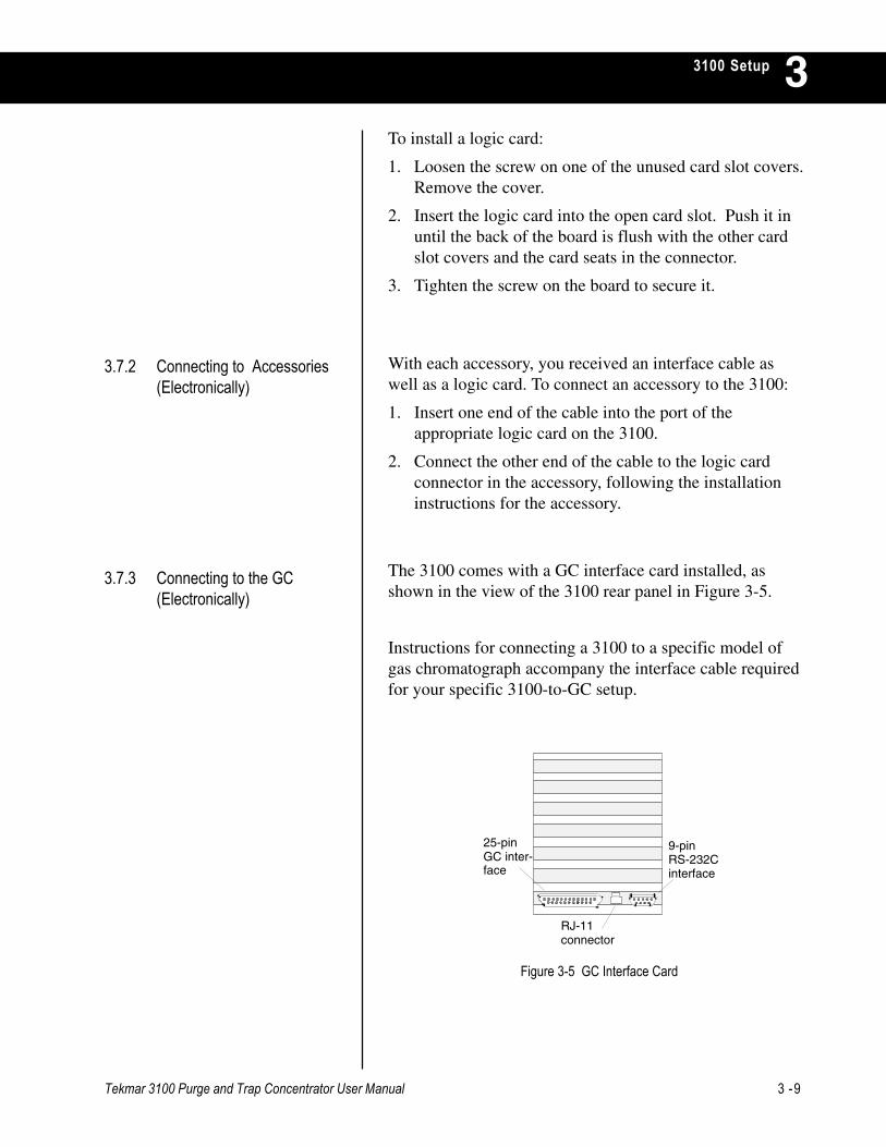
The 3100 comes with a GC interface card installed, asshown in the view of the 3100 rear panel in Figure 3-5.
Instructions for connecting a 3100 to a specific model ofgas chromatograph accompany the interface cable requiredfor your specific 3100-to-GC setup.
3.7.2 Connecting to Accessories(Electronically)
3.7.3 Connecting to the GC(Electronically)
25-pin GC inter-face
RJ-11connector
9-pin RS-232Cinterface
Figure 3-5 GC Interface Card
3 -10 Tekmar 3100 Purge and Trap Concentrator User Manual
3100 Setup33.8 Leak Checking
Guidelines
To ensure accurate, reproducible results from analyticalruns with the 3100, check fittings (pneumatic connections)for leaks. Follow these guidelines when you leak checkyour 3100 installation:
• Leak check after you have completely assembled thesystem and made all pneumatic connections.
• Use an electronic thermal conductivity detector (such asa Tekmar-Dohrmann Gas Leak Detector, P/N 21-0052-000) to check the fittings.
• Use helium (not nitrogen) as the pressurizing gas.(Electronic leak detectors do not reliably detectnitrogen.)
• If an electronic leak detector is not available, you mayuse a 1:1 solution of isopropanol and water. Use thesolution sparingly to avoid contamination.
• Allow the 3100 to warm up for a least thirty minutesbefore you leak check. The fittings need time to reachoperating temperature and expand; otherwise, they willleak.
WARNINGTo leak check, you must remove the 3100's panels. To avoidelectrical shock, do not touch any internal parts except thecontrol knobs. Before you leak check, remove jewelry; itconducts electricity.
Tekmar 3100 Purge and Trap Concentrator User Manual 3 -11
3100 Setup 3
To check for leaks in the sample gas flow lines:
1. Follow the instructions in Section 3.3, Setting SamplePressure.
2. Attach a flow meter to the vent fitting on the left frontpanel of the 3100 to measure the flow rate of the samplegas.
3. Use the knob marked "Sample Flow" to set the samplegas flow to 35 - 40 ml/minute.
4. Put 5 ml of organic-free water in the purge vessel.
5. Do one of the following:
a. Put a 1/16" cap nut on the 3100 vent fitting on thefront panel. Tighten the fitting wrench-tight OR
b. If you have ROM (read-only memory) version 2.10or greater, you can use the software's Leak Checkfeature to cap the vent. This feature causes thesample valve to open and the vent valve to close. Tostart Leak Check, press SHIFT-GOTO, then the Bkey. Next, choose option C. A flashing "L" on thedisplay indicates that Leak Check is on.
6. Time the bubbling in the purge vessel. If the bubblingstops between three to 14 minutes, the system is leaktight; no further leak checking is necessary.
3.8.1 Leak Checking
• Do not use any type of soap solution (for example,Snoop or Detect) to check for leaks. If soap gets intothe lines, it will cause background and adsorption.
• If you tighten fittings before the 3100 has pressurizedand warmed to operating temperature (30 mins.), youcould damage the ferrules by overtightening the nuts.You could also strip the threads on the nuts and not beable to remove them.
• If you find a leak, finger-tighten the nut, then turn 1/4-turn with a wrench. Recheck. If it still leaks, look forother possible causes; do not over-tighten. Leaks canalso be caused by a crack in the line or a damaged nutor ferrule. Also, a part may be of incorrect size ormaterial. If a leak problem persists, call Tekmar-Dohrmann Service.
CAUTION
3 -12 Tekmar 3100 Purge and Trap Concentrator User Manual
3100 Setup3To diagnose a leak:
1. Make sure the leak is not at the capped vent. TheSwagelok nut may be worn.
2. If the bubbling stops before three minutes have elapsed,it is likely that there is a leak upstream of the purgevessel (before the gas flow reaches the purge vessel). Ifa leak is indicated, leave the system in purge with thevent capped. Capping the vent causes pressure toincrease, which exaggerates the leak and makes it easierto find.
3. If the bubbling continues after 14 minutes, a leak existsdownstream of the purge vessel (after the gas flowleaves the purge vessel).
4. Using an electronic leak detector, check the fittings atthe top and bottom of the trap.
5. Check the fittings inside the valve oven of the 3100.
6. Check these five fittings around the glassware on thefront of the 3100:
a. Purge line fitting (at glassware)
b. Purge bulkhead (at the 3100)
c. Sample glassware fitting
d. Sample needle nut
e. Sample valve (three-port)
7. Check the Swagelok fittings inside the 3100.
After you have installed the 3100 and made all pneumaticconnections, the GC column back pressure gauge shouldshow the same reading as before.
• If the gauge reading is higher that its pre-installtionlevel, check the lines for clogs.
• If the gauge reading is lower than its pre-installationlevel, there is a leak. Check fittings with a leak detector;tighten as necessary.

UNDERSTANDING OPERATING STEPS
Chapter 4

Tekmar-3100 Purge and Trap Concentrator User Manual 4 -1
Understanding Operating Steps 44.1 Overview An analytical run on the Tekmar 3100 consists of a
programmed sequence of steps, called a method.
This section performs the following functions:
· Describes the operating steps used by the 3100 invarious analytical configurations and defines the defaultvalues assigned to parameters in each step.
· Tells you which parameters you can program to createcustomized methods.
4.2 Steps in an OperatingSequence
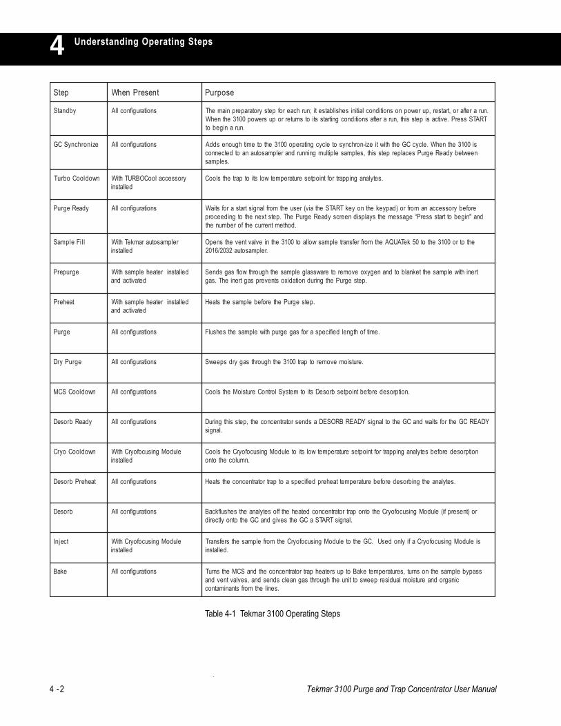
Depending on the system configuration and installedaccessories, the 3100 goes through a programmed sequenceof operating steps. Table 4-1 lists the operating steps inorder of their occurrence. If an operating step is active onlyunder certain conditions (with a specific systemconfiguration or when a specific accessory is installed), thesecond column in the table defines the conditions. The thirdcolumn in the table describes each step.
4 -2 Tekmar 3100 Purge and Trap Concentrator User Manual
Understanding Operating Steps4petS tneserPnehW esopruP
ybdnatS snoitarugifnocllA .nuraretfaro,tratser,purewopnosnoitidnoclaitinisehsilbatseti;nurhcaerofpetsyrotaraperpniamehTTRATSsserP.evitcasipetssiht,nuraretfasnoitidnocgnitratsstiotsnruterropusrewop0013ehtnehW
.nuranigebot
ezinorhcnySCG snoitarugifnocllA si0013ehtnehW.elcycCGehthtiwtiezi-norhcnysotelcycgnitarepo0013ehtotemithguonesddAneewtebydaeRegruPsecalperpetssiht,selpmaselpitlumgninnurdnarelpmasotuanaotdetcennoc
.selpmas
nwodlooCobruT yrosseccalooCOBRUThtiWdellatsni
.setylanagnippartroftniopteserutarepmetwolstiotpartehtslooC
ydaeRegruP snoitarugifnocllA erofebyrosseccanamorfro)dapyekehtnoyekTRATSehtaiv(resuehtmorflangistratsarofstiaWdna"nigebottratssserP“egassemehtsyalpsidneercsydaeRegruPehT.petstxenehtotgnideecorp
.dohtemtnerrucehtforebmuneht
lliFelpmaS relpmasotuaramkeThtiWdellatsni
ehtotro0013ehtot05keTAUQAehtmorfrefsnartelpmaswollaot0013ehtnievlavtnevehtsnepO.relpmasotua2302/6102
egruperP dellatsniretaehelpmashtiWdetavitcadna
trenihtiwelpmasehtteknalbotdnanegyxoevomeroterawssalgelpmasehthguorhtwolfsagsdneS.petsegruPehtgnirudnoitadixostneverpsagtreniehT.sag
taeherP dellatsniretaehelpmashtiWdetavitcadna
.petsegruPehterofebelpmasehtstaeH
egruP snoitarugifnocllA .emitfohtgneldeificepsarofsagegruphtiwelpmasehtsehsulF
egruPyrD snoitarugifnocllA .erutsiomevomerotpart0013ehthguorhtsagyrdspeewS
nwodlooCSCM snoitarugifnocllA .noitprosederofebtnioptesbroseDstiotmetsySlortnoCerutsioMehtslooC
ydaeRbroseD snoitarugifnocllA YDAERCGehtrofstiawdnaCGehtotlangisYDAERBROSEDasdnesrotartnecnoceht,petssihtgniruD.langis
nwodlooCoyrC eludoMgnisucofoyrChtiWdellatsni
noitprosederofebsetylanagnippartroftniopteserutarepmetwolstioteludoMgnisucofoyrCehtslooC.nmulocehtotno
taeherPbroseD snoitarugifnocllA .setylanaehtgnibrosederofeberutarepmettaeherpdeificepsaotpartrotartnecnocehtstaeH
broseD snoitarugifnocllA ro)tneserpfi(eludoMgnisucofoyrCehtotnopartrotartnecnocdetaehehtffosetylanaehtsehsulfkcaB.langisTRATSaCGehtsevigdnaCGehtotnoyltcerid
tcejnI eludoMgnisucofoyrChtiWdellatsni
sieludoMgnisucofoyrCafiylnodesU.CGehtoteludoMgnisucofoyrCehtmorfelpmasehtsrefsnarT.dellatsni
ekaB snoitarugifnocllA ssapybelpmasehtnosnrut,serutarepmetekaBotpusretaehpartrotartnecnocehtdnaSCMehtsnruTcinagrodnaerutsiomlaudiserpeewsottinuehthguorhtsagnaelcsdnesdna,sevlavtnevdna
.senilehtmorfstnanimatnoc
Table 4-1 Tekmar 3100 Operating Steps
Tekmar-3100 Purge and Trap Concentrator User Manual 4 -3
Understanding Operating Steps 44.3 Operating
Cycle Time
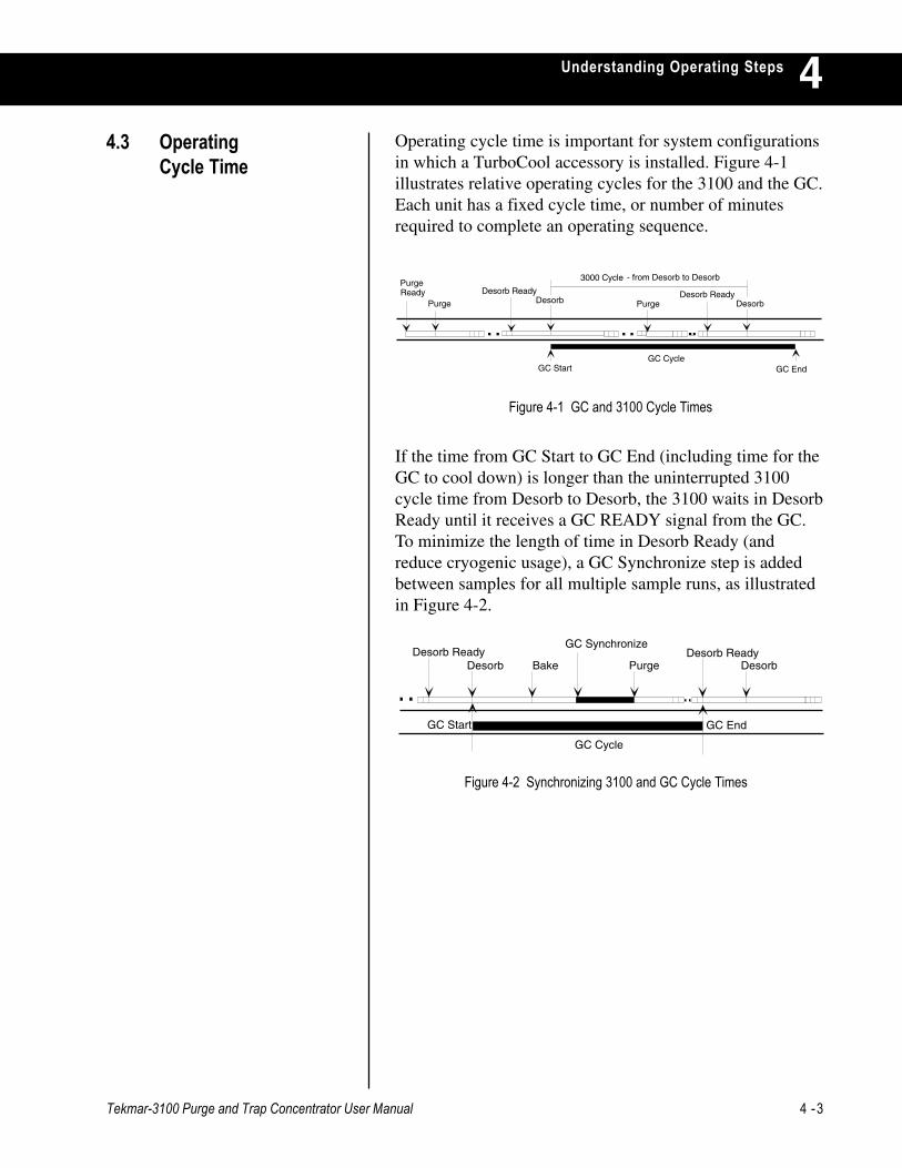
If the time from GC Start to GC End (including time for theGC to cool down) is longer than the uninterrupted 3100cycle time from Desorb to Desorb, the 3100 waits in DesorbReady until it receives a GC READY signal from the GC.To minimize the length of time in Desorb Ready (andreduce cryogenic usage), a GC Synchronize step is addedbetween samples for all multiple sample runs, as illustratedin Figure 4-2.
Figure 4-1 GC and 3100 Cycle Times
Operating cycle time is important for system configurationsin which a TurboCool accessory is installed. Figure 4-1illustrates relative operating cycles for the 3100 and the GC.Each unit has a fixed cycle time, or number of minutesrequired to complete an operating sequence.
PurgeDesorb Ready
Desorb Purge Desorb Ready
Desorb
3000 Cycle
GC CycleGC Start GC End
- from Desorb to Desorb
ReadyPurge
Desorb ReadyDesorb Bake
GC Synchronize
GC Start GC End
Desorb ReadyDesorb
GC Cycle
Purge
Figure 4-2 Synchronizing 3100 and GC Cycle Times
4 -4 Tekmar 3100 Purge and Trap Concentrator User Manual
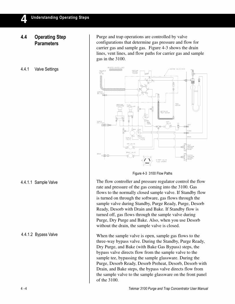
Understanding Operating Steps4Purge and trap operations are controlled by valveconfigurations that determine gas pressure and flow forcarrier gas and sample gas. Figure 4-3 shows the drainlines, vent lines, and flow paths for carrier gas and samplegas in the 3100.
The flow controller and pressure regulator control the flowrate and pressure of the gas coming into the 3100. Gasflows to the normally closed sample valve. If Standby flowis turned on through the software, gas flows through thesample valve during Standby, Purge Ready, Purge, DesorbReady, Desorb with Drain and Bake. If Standby flow isturned off, gas flows through the sample valve duringPurge, Dry Purge and Bake. Also, when you use Desorbwithout the drain, the sample valve is closed.
Figure 4-3 3100 Flow Paths
4.4.1 Valve Settings
4.4 Operating StepParameters
4.4.1.1 Sample Valve
4.4.1.2 Bypass Valve When the sample valve is open, sample gas flows to thethree-way bypass valve. During the Standby, Purge Ready,Dry Purge, and Bake (with Bake Gas Bypass) steps, thebypass valve directs flow from the sample valve to thesample tee, bypassing the sample glassware. During thePurge, Desorb Ready, Desorb Preheat, Desorb, Desorb withDrain, and Bake steps, the bypass valve directs flow fromthe sample valve to the sample glassware on the front panelof the 3100.

Tekmar-3100 Purge and Trap Concentrator User Manual 4 -5
Understanding Operating Steps 4The drain valve opens to allow liquid to flow from thesample glassware to exit at the 3100 drain at the rear of theconcentrator.
The high rate purge (HRP) valve is normally closed. Itworks with the drain valve. When the HRP and drain valvesare open during the Desorb step (when autodrain is on),incoming sample gas is split, allowing flow to pressurizethe sample glassware and force liquid up through theneedle, out of the glassware through the drain on the rear ofthe 3100.
The vent valve opens to allow pass-through flow during theStandby, Purge Ready, Purge, Dry Purge, Bake, and Bakewith Bake Gas Bypass steps. When it is open, gas flowsthrough the sample pathway and out the vent on the front ofthe 3100.
The backflush valve opens to allow pass through flowacross the trap during Bake.
The six-port valve (located inside the valve oven) has twopositions that control the direction of sample and carrier gasflow through the concentrator. The concentrator operateswith two separate gas flows:
• Sample gas enters through the sample gas inlet at theback of the unit and exits through the front panel ventvalve.
• Carrier gas enters through the carrier gas inlet at theback of the unit and proceeds through the transfer lineto the gas chromatograph.
4.4.1.3 Drain Valve
4.4.1.4 HRP Valve
4.4.1.5 Vent Valve
4.4.1.7 Six-Port Valve
4.4.1.6 Backflush Valve
4 -6 Tekmar 3100 Purge and Trap Concentrator User Manual
Understanding Operating Steps4
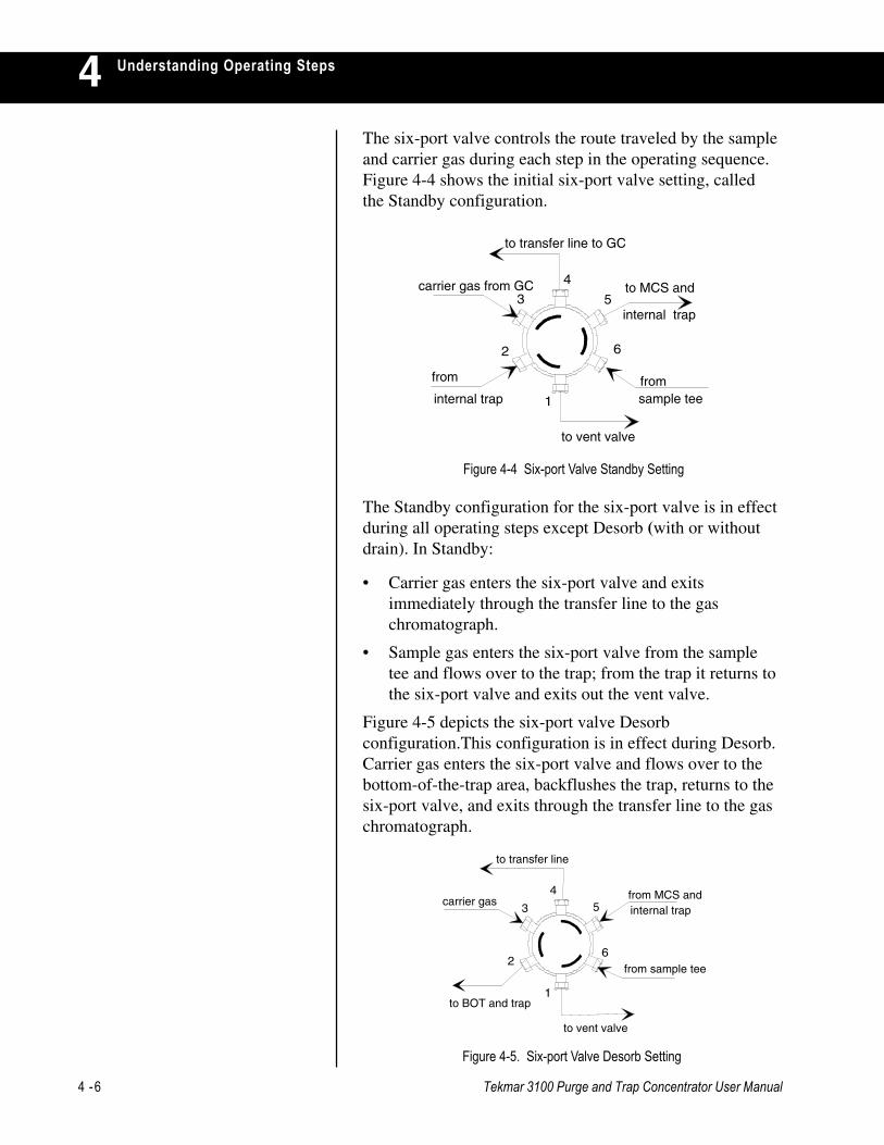
The Standby configuration for the six-port valve is in effectduring all operating steps except Desorb (with or withoutdrain). In Standby:
• Carrier gas enters the six-port valve and exitsimmediately through the transfer line to the gaschromatograph.
• Sample gas enters the six-port valve from the sampletee and flows over to the trap; from the trap it returns tothe six-port valve and exits out the vent valve.
Figure 4-5 depicts the six-port valve Desorbconfiguration.This configuration is in effect during Desorb.Carrier gas enters the six-port valve and flows over to thebottom-of-the-trap area, backflushes the trap, returns to thesix-port valve, and exits through the transfer line to the gaschromatograph.
5
6
4
3
1
2
to vent valve
to BOT and trap
carrier gas
to transfer line
from MCS andinternal trap
from sample tee
Figure 4-5. Six-port Valve Desorb Setting
2
3
4
5
6
1
to vent valve
carrier gas from GC
to transfer line to GC
from
internal trap
to MCS and
internal trap
from sample tee
Figure 4-4 Six-port Valve Standby Setting
The six-port valve controls the route traveled by the sampleand carrier gas during each step in the operating sequence.Figure 4-4 shows the initial six-port valve setting, calledthe Standby configuration.

Tekmar-3100 Purge and Trap Concentrator User Manual 4 -7
Understanding Operating Steps 4The trap pressure control (TPC) valve is a needle valvelocated between the vent valve and the front panel ventopening. The TPC valve regulates back pressure on the trap.Increasing pressure on the trap shifts the partitioning of
volatile analytes between the vapor phase and stationaryphase, allowing the analytes to have increased interactionwith the adsorbent. They do not travel as far into theadsorbent, and, as a result, are released in a tight band upondesorption. This improves peak shape and sensitivity.
The TPC valve is not under program control; you adjust itmanually. At the factory, the TPC valve is set to maintainthe recommended back pressure of 4 psi. Do not set thepressure of the TPC valve equal to or higher than the GCcolumn head pressure. As a rule, the difference between theTPC valve and feed pressure settings should be greater than10 psi. For example, if the feed pressure is 20 psi, set thepressure of the TPC valve less than 10 psi. While TPCvalve pressure can be beneficial at the correct level, settingit too high can cause carryover.
An operating step can define the temperature setpoint forheating or cooling and the length of time during which thetemperature will be maintained at setpoint. Depending onyour system configuration and installed accessory options,you can program methods that specify required time andtemperature values for heating and/or cooling the followingparts:
• Sample heater on the front panel (optional).
• Six-port valve and tee in the valve oven.
• Transfer line heater from the 3100 to the GC.
• Moisture Control System (MCS) just behind the trap.
• Adsorbent trap during Standby, Desorb, and Bake.
• Bottom-of trap (line from the six-port valve to thebottom of the trap).
• Cryofocusing Module at the injection port of the GC (ifused).
• Valve and line temperatures of optional autosampler(s).
4.4.2 Time and TemperatureParameters
4.4.1.8 Trap Pressure Control Valve

4 -8 Tekmar 3100 Purge and Trap Concentrator User Manual
Understanding Operating Steps4
4.5.2 GC Synchronize
Table 4-2 Valve Configuration during Standby and Purge Ready
Before beginning a run, the 3100 is in Standby. Standby isactive until heated (and/or cooled) parts reach theirsetpoints.
4.5 UnderstandingOperating Steps
Figure 4-6 Gas Flow during Standby and Purge Ready
4.5.1 Purge Ready On the first run in a schedule, this step pauses to wait for astart signal. If the 3100 is operating with an autosampler,the autosampler rotates through sam- ple positions until itreaches the starting position specified in the current oper-ating sequence. Figure 4-6 and Table 4-2 show valveconfigurations during Standby and Purge Ready.
1 Only if Standby Flow is on.
If you have installed a TURBOCool accessory, a GCSynchronize step replaces Purge Ready between runs on amultiple sample sequence. During GC Synchronize, the3100 waits before proceeding to the next step. The 3100calculates the length of the delay (up to 1000 minutes),based on the GC cycle time parameter. Valve settingsduring this step do not change.
Valve Sample Bypass Vent HRP Drain 6-port BackflushDesignation:Position: open1 on1 open1 closed closed Standby closed

Tekmar-3100 Purge and Trap Concentrator User Manual 4 -9
Understanding Operating Steps 4If your configuration includes an AQUATek 50 automaticsampler, during the Sample Fill time specified for this step,the sample volume is transfer-red into the sample glasswareon the 3100 or on the ALS autosampler. For moreinformation, refer to the AQUATek 50 User Manual.
If you have installed a TURBOCool accessory, this stepcools the TURBO-Cool trap to its low temperature setpoint(TURBOCool Temp).
If you installed and turned on a sample heater, the 3100 canoperate with Prepurge and Preheat steps. During Prepurge,the bypass valve allows purge gas to flow through thesample glassware for a programmed time (Prepurge Time)before the sample is heated. The flow of gas blankets thesample with inert gas to avoid heat-induced sampleoxidation.
During Preheat, the sample is heated to the programmedsample temperature setpoint (Sample Temp) for aprogrammed time (Preheat Time). This step should be justlong enough to heat the sample to temperature. It is best toavoid long preheat times. There is no Purge flow duringPreheat.
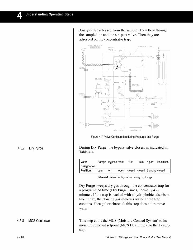
During Purge, the sample is purged with sample gas for thetime specified in the Purge Time parameter. Table 4-3 andFigure 4-7 show the change in valve configurations forPrepurge and Purge.
4.5.4 TURBO Cooldown
4.5.3 Sample Fill
4.5.5 Prepurge and Preheat
4.5.6 Purge
Table 4-3 Valve Configuration during Purge
Gas enters the sample gas inlet, flows through the pressureand flow regulators, through the sample and bypass valves,to the sample glassware.
Valve Sample Bypass Vent HRP Drain 6-port BackflushDesignation:Position: open off open closed closed Standby closed
4 -10 Tekmar 3100 Purge and Trap Concentrator User Manual
Understanding Operating Steps4Analytes are released from the sample. They flow throughthe sample line and the six-port valve. Then they areadsorbed on the concentrator trap.
During Dry Purge, the bypass valve closes, as indicated inTable 4-4.
Dry Purge sweeps dry gas through the concentrator trap fora programmed time (Dry Purge Time), normally 4 - 6minutes. If the trap is packed with a hydrophobic adsorbentlike Tenax, the flowing gas removes water. If the trapcontains silica gel or charcoal, this step does not removewater.
This step cools the MCS (Moisture Control System) to itsmoisture removal setpoint (MCS Des Temp) for the Desorbstep.
Figure 4-7 Valve Configuration during Prepurge and Purge
4.5.7 Dry Purge
Table 4-4 Valve Configuration during Dry Purge
4.5.8 MCS Cooldown
Valve Sample Bypass Vent HRP Drain 6-port BackflushDesignation:Position: open on open closed closed Standby closed
Tekmar-3100 Purge and Trap Concentrator User Manual 4 -11
Understanding Operating Steps 4During Desorb Ready, valve configurations change, asshown in Table 4-5.
The 3100 outputs a Desorb Ready signal to the GC andwaits for a GC Ready signal in return. There is no Purge gasflow. Temperature setpoints are maintained, unless the MCSand Cryofocusing Module are cooling to their setpoints(MCS Des Temp and CryoFocus Temp).
The Cryofocusing Module cools desorbed analytes andfocuses them on the head of the column before they areintroduced into the GC. Every operating sequence does notuse a Cryofocusing Module; this step is not required unlessa Cryofocusing Module is installed. Setting theCryoFocuser parameter to "off" eliminates the cryofocusingsteps from the operating sequence. The CryofocusingModule will go to the Cryo Standby temperature. Dur-ingCryofocusing Module Cooldown, the unit is cooled to itssetpoint (CryoFocus Temp).
During Desorb Preheat, the concentrator trap is heated to aspecified temperature (Desorb Preheat) in preparation foranalyte transfer from the trap to the GC. There is no flowthrough the concentrator trap during Desorb Preheat.
4.5.9 Desorb Ready
Table 4-5 Valve Configuration during Desorb Ready
4.5.10 Cryofocusing ModuleCooldown
4.5.11 Desorb Preheat
Valve Sample Bypass Vent HRP Drain 6-port BackflushDesignation:Position: closed off closed closed closed Standby closed
4 -12 Tekmar 3100 Purge and Trap Concentrator User Manual
Understanding Operating Steps4
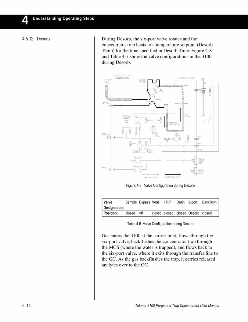
Gas enters the 3100 at the carrier inlet, flows through thesix-port valve, backflushes the concentrator trap throughthe MCS (where the water is trapped), and flows back tothe six-port valve, where it exits through the transfer line tothe GC. As the gas backflushes the trap, it carries releasedanalytes over to the GC.
Table 4-6 Valve Configuration during Desorb
Figure 4-8 Valve Configuration during Desorb
Valve Sample Bypass Vent HRP Drain 6-port BackflushDesignation:Position: closed off closed closed closed Desorb closed
4.5.12 Desorb During Desorb, the six-port valve rotates and theconcentrator trap heats to a temperature setpoint (DesorbTemp) for the time specified in Desorb Time. Figure 4-8and Table 4-7 show the valve configurations in the 3100during Desorb.
Tekmar-3100 Purge and Trap Concentrator User Manual 4 -13
Understanding Operating Steps 4If the 3100 is set to drain during Desorb, the HRP, sample,and drain valves are open, as shown in Table 4-7.
4.5.13 Desorb with Drain
Table 4-7 Valve Configuration during Desorb with Drain
This is a timed step (specified by the Inject Time parameter)during which the Cryofocusing Module is heated to aprogrammed setpoint (Cryo Inj Temp). Heat releases theanalytes that had been immobilized on the CryofocusingModule column.
Note: Bake and Cryofocusing Inject begin at the same time.
Bake cleans out the sample pathway by heating the MCSand the concentrator trap to their programmed bake outsetpoints (MCS Bake Temp and Trap Bake Temp) andblowing clean gas through the 3100 for the length of timespecified in the Bake Time parameter.
During Bake with Bake Gas Bypass (BGB) off, gas followsthe Purge flow path through the concentrator and glasswareto sweep out all moisture and residual analytes. If theautodrain is on (i.e., drinking water samples), BGB shouldbe off. This allows gas to dry out the glassware. If theautodrain is off (i.e., soils and wastewater samples), BGBshould be on. With BGB on, there is no flow through thesample glassware. This prevents additional analytes being“purged” onto the trap during the Bake mode.
4.5.14 Cryofocusing Inject
4.5.15 Bake
Valve Sample Bypass Vent HRP Drain 6-port BackflushDesignation:Position: open off closed open open Desorb closed

USING TEKLINK TO PROCESS SAMPLES
Chapter 5

Tekmar 3100 Purge and Trap Concentrator User Manua l 5 -1
Using TekLink to Process Samples 55.1 Installing TekLink This section offers information and instructions on system
requirements, making a backup copy of the program disk,and installing TekLink onto your hard drive.
To install and use TekLink, you need an 80386 or highercomputer with Microsoft Windows 3.1 or greater installed.Your system should have a hard drive that has at least twomegabytes (MB) of free space and a floppy disk drive thatreads 1.44MB (3 1/2”) diskettes.
Before you install TekLink onto your hard drive, make abackup copy of the diskette(s) and use the backup forinstallation. Write-protect your backup copy to protect itfrom accidentally being copied over. Store the original in asecure place.
Note: Microsoft Windows version 3.1 (or greater) or Windows 95must be installed on your computer before you can installTekLink.
1. Start Windows and insert your backup copy of TekLinkinto the appropriate floppy drive.
2. To begin the TekLink installation:
Windows 3.x:
• Choose File > Run in Program Manager.
Windows 95:
• Choose Start > Run...
3. Type A:\SETUP or B:\SETUP (depending on the driveyou are using) in the Run dialog box and click OK.
4. Follow the screen prompts. The first screen that appearsis the installation welcome screen (see figure 3.1.3.1).
5.1.1 System Requirements
5.1.2 Making a Backup Copy ofthe Installation Disk
5.1.3 To Install TekLink

5 -2 Tekmar 3100 Purge and Trap Concentrator User Manua l
Using TekLink to Process Samples5
5. Click Next.
6. The next installation screen appears:
7. Select a destination location for TekLink. C:\TEK3100is the default directory. You may Click Browse to selectanother file path.
8. Click Next.
9. You will then be prompted to select a Program Folderfor TekLink. The default folder is TekLink 3100.
Figure 3.1.3.1 Installation Welcome Screen
Figure 3.1.3.2 Installation Choose Destination Location Screen
Figure 3.1.3.3 Installation Select Program Folder Screen
Tekmar 3100 Purge and Trap Concentrator User Manua l 5 -3
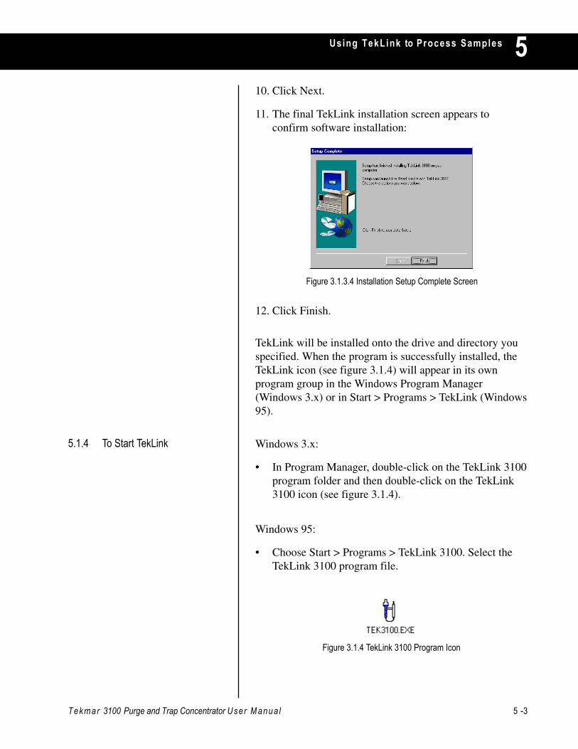
Using TekLink to Process Samples 510. Click Next.
11. The final TekLink installation screen appears toconfirm software installation:
12. Click Finish.
TekLink will be installed onto the drive and directory youspecified. When the program is successfully installed, theTekLink icon (see figure 3.1.4) will appear in its ownprogram group in the Windows Program Manager(Windows 3.x) or in Start > Programs > TekLink (Windows95).
Windows 3.x:
• In Program Manager, double-click on the TekLink 3100program folder and then double-click on the TekLink3100 icon (see figure 3.1.4).
Windows 95:
• Choose Start > Programs > TekLink 3100. Select theTekLink 3100 program file.
Figure 3.1.3.4 Installation Setup Complete Screen
5.1.4 To Start TekLink
Figure 3.1.4 TekLink 3100 Program Icon
5 -4 Tekmar 3100 Purge and Trap Concentrator User Manua l
Using TekLink to Process Samples5The 3100 sample concentrator processes liquid or soilsamples for analysis by gas chromatography and operateautomatically, under microprocessor control, to process asingle front-panel sample or multiple samples loaded froman autosampler. When programmed with custom methods,this system can operate at different time and temperatureparameters and run different analytical sequences onspecified samples.
You can program custom operating sequences for up tofour concentrators by using a personal computer runningTekLink. TekLink makes it possible for you to use apersonal computer running Microsoft Windows to monitor,schedule, and control the operation of one, two, three, orfour concentrators.
Before you begin setting up methods and running samples,please familiarize yourself with the TekLink software asdescribed in this section. TekLink must recognize and beconfigured correctly with the concentrator/autosampler inorder to run properly.
5.2 Configuring theConcentrator withTekLink
5.2.1 Flash Upgrading the 3100ROM
Tekmar-Dohrmann is committed to continuous productenhancement. The 3100 memory board ROM is flashupgradable and can be upgraded easily by running the FlashUpgrade program that is included with TekLink.
If you ever need to flash upgrade the 3100 memory boardROM, please follow the instructions in section 3.2.1.1
Tekmar 3100 Purge and Trap Concentrator User Manua l 5 -5
Using TekLink to Process Samples 5 5.2.1.1 Performing the Flash
Upgrade1. Open the Flash program:
Windows 3.x:
• In Program Manager, double-click on the TekLink3100 program folder and then double-click on theFlash program icon (see figure 3.2.1.1a).
Windows 95:
• Choose Start > Programs > TekLink 3100. Selectthe Flash program file.
2. Click on File and select Configure Ports.
Figure 3.2.1.1a TekLink 3100 Flash Program Icon
3. Enter the Com Port number the 3100 unit is connectedto.
4. Click OK.
Figure 3.2.1.1b TekLink 3100 Flash Configure Ports
Figure 3.2.1.1c TekLink 3100 Flash Com Port Setup

5 -6 Tekmar 3100 Purge and Trap Concentrator User Manua l
Using TekLink to Process Samples5
6. Select the ROM Image File furnished to you byTekmar-Dohrmann. The file will have the version namefollowed by the .bin extension.
5. Select File > Send Flash Image to Instrument.
7. Click OK.
8. You will see the Flash Burning Process in this window.There are four indicators depicting the burningprogress:
a) Stage reflects the current state for each sector
b) Current Sector is a progress indicator
c) Error Count indicates the number of errorsencountered while trying to communicate with the3100. After 3 errors, the Flash program will abort.
d) Verify Errors indicates the number of errorsencountered while trying to verify a sector on the3100. After 3 errors, the Flash program will abort.
Figure 3.2.1.1d Send Flash Image to Instrument
Figure 3.2.1.1e Select File to Send
Figure 3.2.1.1f Flash Burning Process Window

Tekmar 3100 Purge and Trap Concentrator User Manua l 5 -7
Using TekLink to Process Samples 59. If the Flash programs aborts, one of three messages will
appear:
a) Connect Error
b) Lost Communication with Instrument
c) Can't Program Current Sector
Check the TekLink port configuration to verify thecorrect com port setup. If you continue to encountererrors, please call Tekmar-Dohrmann's TechnicalSupport Department. Inside the US and Canada: (800)874-2004; outside the US and Canada: (513) 247-7000.
10. When Flash programming is successful, a statuswindow will appear
11. If Flash programming is complete, with no errors, exitout of the Flash program, power down the 3100, thenpower up the 3100. Your 3100 should now be updatedwith the new ROM version.
12. To verify the programming of your ROM upgrade,launch TekLink 3100 and click on the Help menu.Select About TekLink. Your new ROM version, listedafter "3100 Firmware Version", should correspond withthe new ROM version programmed.
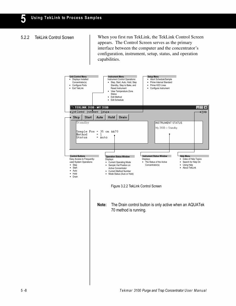
5 -8 Tekmar 3100 Purge and Trap Concentrator User Manua l
Using TekLink to Process Samples5When you first run TekLink, the TekLink Control Screenappears. The Control Screen serves as the primaryinterface between the computer and the concentrator’sconfiguration, instrument, setup, status, and operationcapabilities.
5.2.2 TekLink Control Screen
Figure 3.2.2 TekLink Control Screen
Unit Control MenuDisplays InstalledConcentrator(s)Configure PortsExit TekLink
Instrument MenuInstrument Control Operations:
Step, Start, Auto, Hold, StepStandby, Step to Bake, andReset InstrumentView Temperature ZoneStatusEdit MethodEdit Schedule
Setup MenuAbort Schedule/SamplePrime Internal StandardPrime H2O LinesConfigure Instrument
Control ButtonsEasy Access to Frequently-used System Operations:
StepStartAutoHoldDrain
Operation Status WindowDisplays:
Current Operating ModeSample Vial Position onActive ConcentratorCurrent Method NumberMode Status (Auto or Hold)
Instrument Status WindowDisplays:
The Status of the ActiveConcentrator(s)
Help MenuIndex of Help TopicsSearch for Help OnUsing HelpAbout TekLink
Note: The Drain control button is only active when an AQUATek70 method is running.
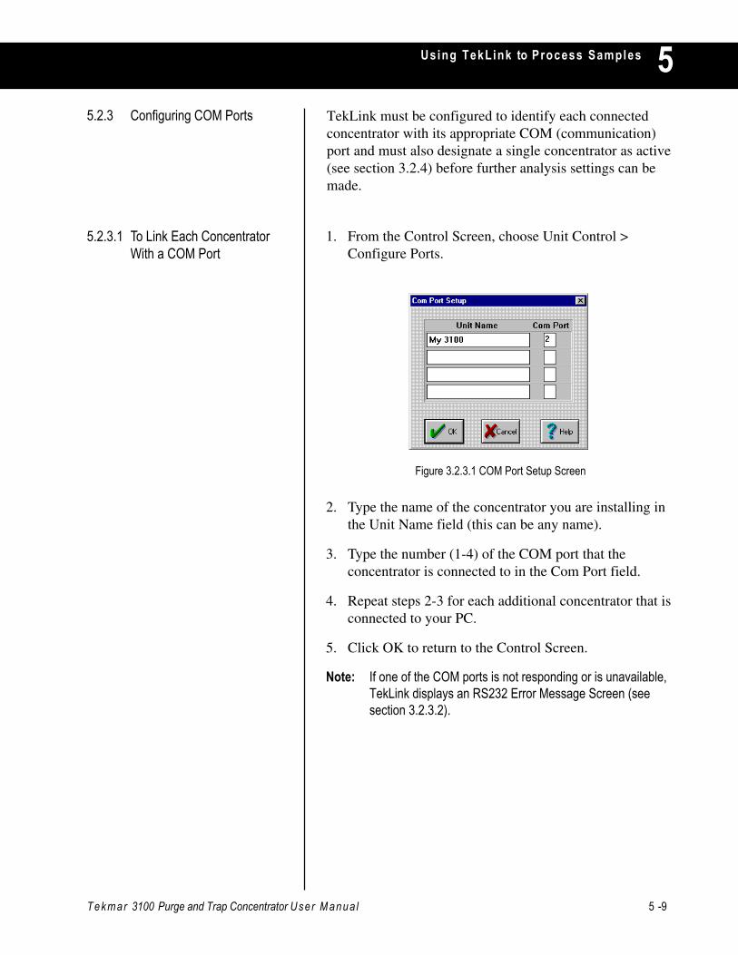
Tekmar 3100 Purge and Trap Concentrator User Manua l 5 -9
Using TekLink to Process Samples 5TekLink must be configured to identify each connectedconcentrator with its appropriate COM (communication)port and must also designate a single concentrator as active(see section 3.2.4) before further analysis settings can bemade.
5.2.3 Configuring COM Ports
1. From the Control Screen, choose Unit Control >Configure Ports.
2. Type the name of the concentrator you are installing inthe Unit Name field (this can be any name).
3. Type the number (1-4) of the COM port that theconcentrator is connected to in the Com Port field.
4. Repeat steps 2-3 for each additional concentrator that isconnected to your PC.
5. Click OK to return to the Control Screen.
Note: If one of the COM ports is not responding or is unavailable,TekLink displays an RS232 Error Message Screen (seesection 3.2.3.2).
Figure 3.2.3.1 COM Port Setup Screen
5.2.3.1 To Link Each ConcentratorWith a COM Port
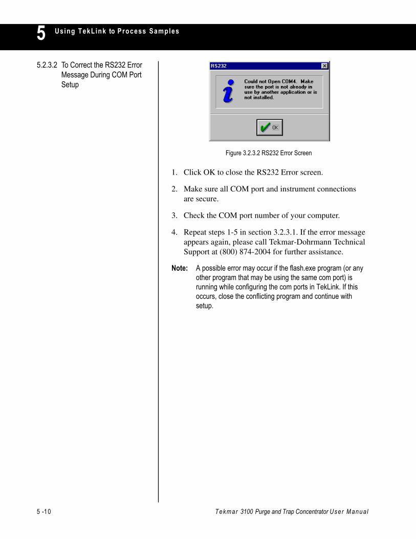
5 -10 Tekmar 3100 Purge and Trap Concentrator User Manua l
Using TekLink to Process Samples5
1. Click OK to close the RS232 Error screen.
2. Make sure all COM port and instrument connectionsare secure.
3. Check the COM port number of your computer.
4. Repeat steps 1-5 in section 3.2.3.1. If the error messageappears again, please call Tekmar-Dohrmann TechnicalSupport at (800) 874-2004 for further assistance.
Note: A possible error may occur if the flash.exe program (or anyother program that may be using the same com port) isrunning while configuring the com ports in TekLink. If thisoccurs, close the conflicting program and continue withsetup.
5.2.3.2 To Correct the RS232 ErrorMessage During COM PortSetup
Figure 3.2.3.2 RS232 Error Screen
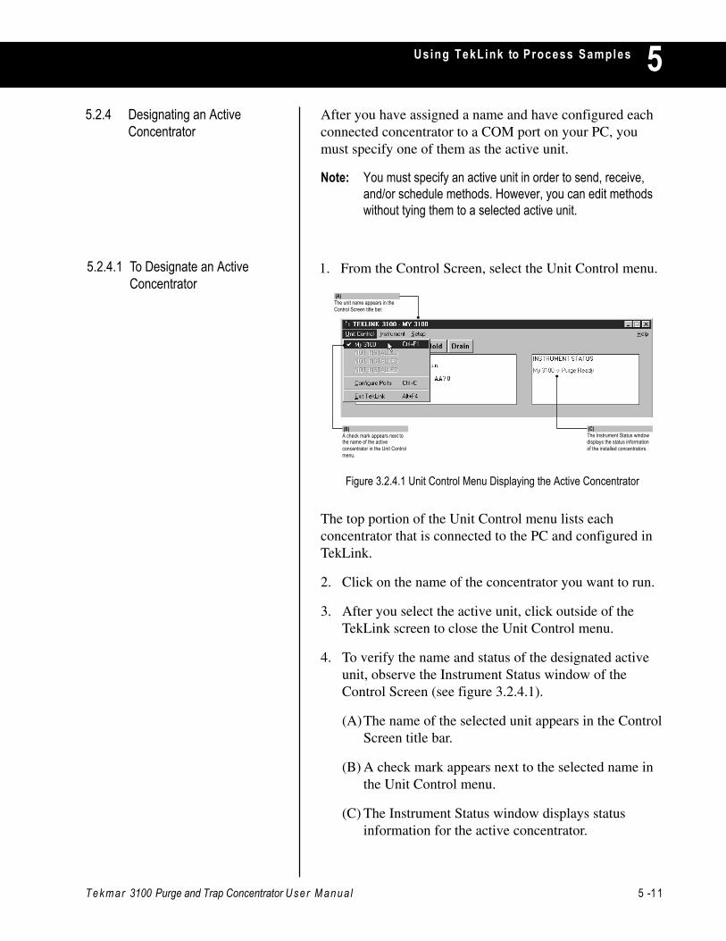
Tekmar 3100 Purge and Trap Concentrator User Manua l 5 -11
Using TekLink to Process Samples 55.2.4 Designating an Active
ConcentratorAfter you have assigned a name and have configured eachconnected concentrator to a COM port on your PC, youmust specify one of them as the active unit.
Note: You must specify an active unit in order to send, receive,and/or schedule methods. However, you can edit methodswithout tying them to a selected active unit.
5.2.4.1 To Designate an ActiveConcentrator
The top portion of the Unit Control menu lists eachconcentrator that is connected to the PC and configured inTekLink.
2. Click on the name of the concentrator you want to run.
3. After you select the active unit, click outside of theTekLink screen to close the Unit Control menu.
4. To verify the name and status of the designated activeunit, observe the Instrument Status window of theControl Screen (see figure 3.2.4.1).
(A)The name of the selected unit appears in the ControlScreen title bar.
(B) A check mark appears next to the selected name inthe Unit Control menu.
(C) The Instrument Status window displays statusinformation for the active concentrator.
Figure 3.2.4.1 Unit Control Menu Displaying the Active Concentrator
1. From the Control Screen, select the Unit Control menu.
(A)The unit name appears in theControl Screen title bar.
(B)A check mark appears next tothe name of the activeconcentrator in the Unit Controlmenu.
(C)The Instrument Status windowdisplays the status informationof the installed concentrators.
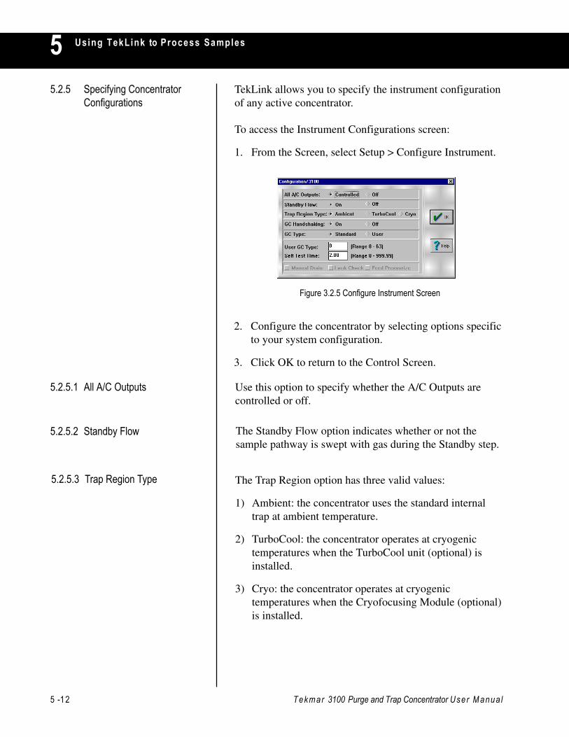
5 -12 Tekmar 3100 Purge and Trap Concentrator User Manua l
Using TekLink to Process Samples55.2.5 Specifying Concentrator
ConfigurationsTekLink allows you to specify the instrument configurationof any active concentrator.
To access the Instrument Configurations screen:
1. From the Screen, select Setup > Configure Instrument.
5.2.5.1 All A/C Outputs
2. Configure the concentrator by selecting options specificto your system configuration.
3. Click OK to return to the Control Screen.
Use this option to specify whether the A/C Outputs arecontrolled or off.
5.2.5.2 Standby Flow
5.2.5.3 Trap Region Type
The Standby Flow option indicates whether or not thesample pathway is swept with gas during the Standby step.
The Trap Region option has three valid values:
1) Ambient: the concentrator uses the standard internaltrap at ambient temperature.
2) TurboCool: the concentrator operates at cryogenictemperatures when the TurboCool unit (optional) isinstalled.
3) Cryo: the concentrator operates at cryogenictemperatures when the Cryofocusing Module (optional)is installed.
Figure 3.2.5 Configure Instrument Screen
Tekmar 3100 Purge and Trap Concentrator User Manua l 5 -13
Using TekLink to Process Samples 5
5.2.5.10 Feed Pressurize Mode
5.2.5.9 Leak Check Mode
5.2.5.8 Manual Drain Mode
5.2.5.7 Self-Test Time
5.2.5.6 User GC Type
5.2.5.5 GC Type
The vent allows sample gas to exit the sample pathwaythrough a front panel vent. When it is closed, pressurebuilds up in the sample pathway. This is used to set thefeed pressure (it eliminates Trap Pressure Control [TPC]effects).
You can configure the concentrator for either a Standard orUser type GC Port. The GC type classification is based onthe input-output characteristics of the GC as it interactswith the concentrator.
If you have ordered an interface cable, the User GC Type isprovided with the cable. If you have not ordered a cable,you must know the characteristics of the input and outputsignals traveling to and from the GC to determine the GCUser Type.
The Self-Test Time option allows you to specify a Self-TestTime other than the default.
The drain valve allows the sample glassware to be emptied.When it is open, liquid and gas can be forced out of thesample glassware into the drain system and out the backpanel drain.
The Leak Check Mode option is only accessible duringPurge mode.
5.2.5.4 GC Handshaking The GC Handshaking option specifies GC handshakingcharacteristics.
A) On normally operates the GC’s port.
B) Off operates the GC with no input or output signalsbetween the concentrator and the GC.

5 -14 Tekmar 3100 Purge and Trap Concentrator User Manua l
Using TekLink to Process Samples5After you have installed and configured the concentrator,you can create customized methods (operating sequences)for sample processing that meet your analyticalrequirements.
After you have connected the required concentrator(s) andconfigured your PC’s COM ports to recognize theconnected units, you can use the Method Editor to reviewand edit methods.
5.3 Using Methods
To access the Method Editor screen:
1. From the Control Screen, select Instrument > EditMethod.
5.3.1 Understanding the MethodEditor Screen
Figure 3.3.1 Method Editor Screen
(A)Method Editor File andCommunication menus
(D)Notes Text Box
(E)Min/Max Display Field
(B)Current method filenamedisplayed in the TekLink titlebar
(C)Method Parameter Values

Tekmar 3100 Purge and Trap Concentrator User Manua l 5 -15
Using TekLink to Process Samples 55.3.1.1 Default 3100 Method
Parameter ValuesAt first power up, the concentrator is scheduled to run3100.mt3 which is the 3100 default front panel method.The concentrator automatically performs self tests andremains in Standby until all heaters and coolers havereached their default temperature setpoints. Whentemperature setpoints have been reached, the concentratorgoes into Purge Ready mode. At this point, you can eitherpress the Start control button to begin running 3100.mt3with its default parameters or create, change, or selectanother method schedule.
The default 3100 method file, 3100.mt3, is the defaultmethod specifically configured for the 3100 and 3100.
Note: The 3100 method parameter defaults are guidelines. Youmay need to edit certain values depending on your analysisrequirements.
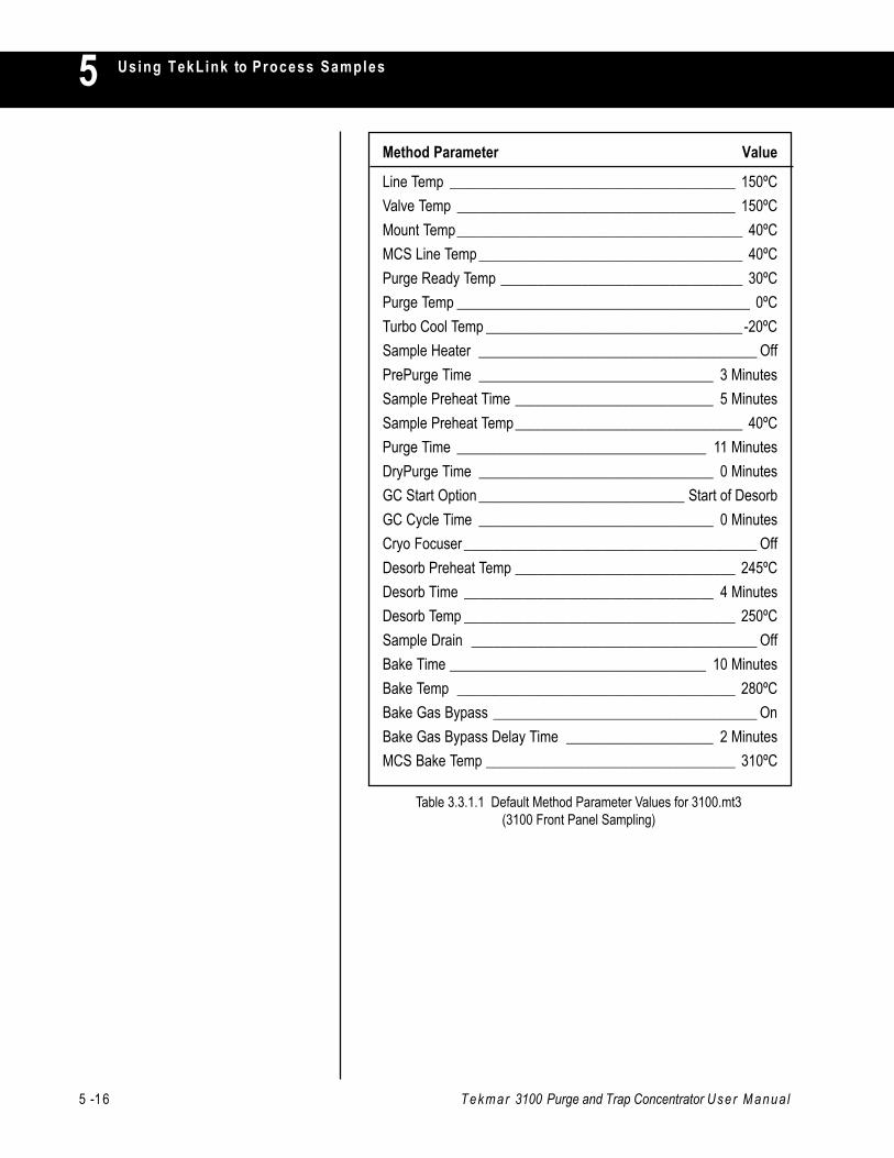
5 -16 Tekmar 3100 Purge and Trap Concentrator User Manua l
Using TekLink to Process Samples5Method Parameter Value
Line Temp _______________________________________ 150ºCValve Temp ______________________________________ 150ºCMount Temp_______________________________________ 40ºCMCS Line Temp ____________________________________ 40ºCPurge Ready Temp _________________________________ 30ºCPurge Temp ________________________________________ 0ºCTurbo Cool Temp ___________________________________-20ºCSample Heater ______________________________________ OffPrePurge Time ________________________________ 3 MinutesSample Preheat Time ___________________________ 5 MinutesSample Preheat Temp_______________________________ 40ºCPurge Time __________________________________ 11 MinutesDryPurge Time ________________________________ 0 MinutesGC Start Option ____________________________ Start of DesorbGC Cycle Time ________________________________ 0 MinutesCryo Focuser ________________________________________ OffDesorb Preheat Temp ______________________________ 245ºCDesorb Time __________________________________ 4 MinutesDesorb Temp _____________________________________ 250ºCSample Drain _______________________________________ OffBake Time ___________________________________ 10 MinutesBake Temp ______________________________________ 280ºCBake Gas Bypass ____________________________________ OnBake Gas Bypass Delay Time ____________________ 2 MinutesMCS Bake Temp __________________________________ 310ºC
Table 3.3.1.1 Default Method Parameter Values for 3100.mt3(3100 Front Panel Sampling)

Tekmar 3100 Purge and Trap Concentrator User Manua l 5 -17
Using TekLink to Process Samples 5
To load a method from the disk:
1. From the Method Editor screen, select File > LoadMethod From Disk.
Figure 3.3.2.1 Select Method to Load Screen
2. Select the method file you want to load.
3. Click OK to return to the Method Editor screen. Allparameters will reflect the values of the loaded method.
The File menu (see figure 3.3.2) of the Method Editorscreen contains options for loading, saving, printing, anddeleting method files.
5.3.2. Method Editor File Menu
Figure 3.3.2 Method Editor File Menu
5.3.2.1 Load Method From Disk TekLink contains one default method file for the 3100.Select one to view and edit. All method filenames end with.mt3. Please review table 3.3.1.1 for default parametervalues.
Note: You cannot load method files from previous versions ofTekLink.
5 -18 Tekmar 3100 Purge and Trap Concentrator User Manua l
Using TekLink to Process Samples55.3.2.2 Save Method to Disk Select File > Save Method to Disk to save the current
method file.
5.3.2.3 Save Method As... Select File > Save Method As... to save the current methodconfiguration under a new filename.
5.3.2.4 Print Method From Disk Select File > Print Method From Disk to print out theparameter listing of a method file.
5.3.2.5 Delete Method From Disk Select File > Delete Method From Disk to permanentlyremove a saved method file from your hard drive.
5.3.2.6 Exit Method Editor Select File > Exit Method Editor to exit out of the MethodEditor screen and return to the Control screen.
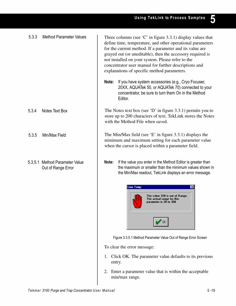
Tekmar 3100 Purge and Trap Concentrator User Manua l 5 -19
Using TekLink to Process Samples 5
Note: If the value you enter in the Method Editor is greater thanthe maximum or smaller than the minimum values shown inthe Min/Max readout, TekLink displays an error message.
To clear the error message:
1. Click OK. The parameter value defaults to its previousentry.
2. Enter a parameter value that is within the acceptablemin/max range.
Figure 3.3.5.1 Method Parameter Value Out of Range Error Screen
The Notes text box (see ‘D’ in figure 3.3.1) permits you tostore up to 200 characters of text. TekLink stores the Noteswith the Method File when saved.
5.3.4 Notes Text Box
The Min/Max field (see ‘E’ in figure 3.3.1) displays theminimum and maximum setting for each parameter valuewhen the cursor is placed within a parameter field.
5.3.5 Min/Max Field
5.3.5.1 Method Parameter ValueOut of Range Error
Three columns (see ‘C’ in figure 3.3.1) display values thatdefine time, temperature, and other operational parametersfor the current method. If a parameter and its value aregrayed out (or uneditable), then the accessory required isnot installed on your system. Please refer to theconcentrator user manual for further descriptions andexplanations of specific method parameters.
Note: If you have system accessories (e.g., Cryo Focuser,20XX, AQUATek 50, or AQUATek 70) connected to yourconcentrator, be sure to turn them On in the MethodEditor.
5.3.3 Method Parameter Values
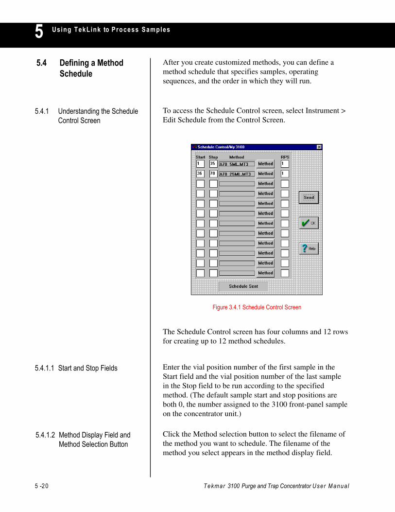
5 -20 Tekmar 3100 Purge and Trap Concentrator User Manua l
Using TekLink to Process Samples55.4 Defining a Method
ScheduleAfter you create customized methods, you can define amethod schedule that specifies samples, operatingsequences, and the order in which they will run.
5.4.1 Understanding the ScheduleControl Screen
To access the Schedule Control screen, select Instrument >Edit Schedule from the Control Screen.
Figure 3.4.1 Schedule Control Screen
The Schedule Control screen has four columns and 12 rowsfor creating up to 12 method schedules.
5.4.1.1 Start and Stop Fields Enter the vial position number of the first sample in theStart field and the vial position number of the last samplein the Stop field to be run according to the specifiedmethod. (The default sample start and stop positions areboth 0, the number assigned to the 3100 front-panel sampleon the concentrator unit.)
5.4.1.2 Method Display Field andMethod Selection Button
Click the Method selection button to select the filename ofthe method you want to schedule. The filename of themethod you select appears in the method display field.
Tekmar 3100 Purge and Trap Concentrator User Manua l 5 -21
Using TekLink to Process Samples 55.4.1.3 RPS (Runs Per Sample)
FieldEnter the number of times each sample will be run.
5.4.1.4 Min/Max Field The Min/Max parameter status field at the bottom of theSchedule Control screen displays the minimum andmaximum autosampler vial positions for the selectedmethod.
5.4.1.10 OK Schedule Button
5.4.1.11 Schedule Control HelpButton
The Send button sends the currently displayed schedule tothe active concentrator.
The OK button exits the Schedule Control screen andreturns to the Control Screen.
Note: You will not be prompted to save the current schedule if ithas changed or if you have not already saved it.
The Help button accesses online help information about theSchedule Control screen.
5.4.1.9 Send Schedule Button
5.4.1.5 Load Schedule Button
5.4.1.6 Save Schedule Button
5.4.1.7 Print Schedule Button
5.4.1.8 Delete Schedule LineButton
Press the Load button in the Schedule Control window toopen up a saved schedule file. The file extension for allsaved schedules is “.sch”.
Press the Save button in the Schedule Control window tosave the current schedule setup information to disk. The fileextension for all saved schedules is “.sch”.
Press the Print button in the Schedule Control window tosend the current schedule information to the default printer.
Press the Del Line button in the Schedule Control windowto delete the line in the current schedule. Make sure thatyou place the cursor somewhere in the line to be deleted.

5 -22 Tekmar 3100 Purge and Trap Concentrator User Manua l
Using TekLink to Process Samples5You can use the Schedule Control screen to set up a methodschedule, or processing timetable, for running samples.When you use the concentrator without an autosampler, youspecify the number and sequence of methods to be run on asingle sample.
When you use the concentrator with one or moreautosamplers, you set up a method schedule that defines:
• The method(s) to be run.
• Start and stop positions for each method.
• A sequential order for each sample to be run.
• The number of runs per sample.
You must use the Schedule Control screen to set up aschedule, even if you are running a front-panel sampleposition with the concentrator.
You can enter any desired method schedule and send it tothe selected concentrator within the Schedule Controlscreen. Use the worksheet included in your concentratoruser manual to develop a method schedule.
5.4.2 Scheduling Runs
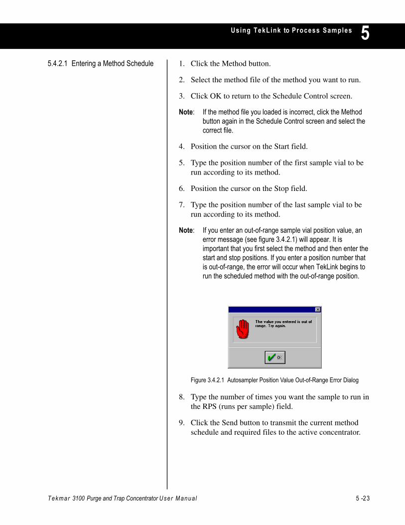
Tekmar 3100 Purge and Trap Concentrator User Manua l 5 -23
Using TekLink to Process Samples 55.4.2.1 Entering a Method Schedule 1. Click the Method button.
2. Select the method file of the method you want to run.
3. Click OK to return to the Schedule Control screen.
Note: If the method file you loaded is incorrect, click the Methodbutton again in the Schedule Control screen and select thecorrect file.
4. Position the cursor on the Start field.
5. Type the position number of the first sample vial to berun according to its method.
6. Position the cursor on the Stop field.
7. Type the position number of the last sample vial to berun according to its method.
Note: If you enter an out-of-range sample vial position value, anerror message (see figure 3.4.2.1) will appear. It isimportant that you first select the method and then enter thestart and stop positions. If you enter a position number thatis out-of-range, the error will occur when TekLink begins torun the scheduled method with the out-of-range position.
Figure 3.4.2.1 Autosampler Position Value Out-of-Range Error Dialog
8. Type the number of times you want the sample to run inthe RPS (runs per sample) field.
9. Click the Send button to transmit the current methodschedule and required files to the active concentrator.
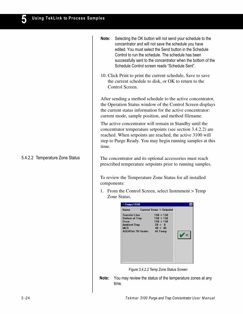
5 -24 Tekmar 3100 Purge and Trap Concentrator User Manua l
Using TekLink to Process Samples5
After sending a method schedule to the active concentrator,the Operation Status window of the Control Screen displaysthe current status information for the active concentrator:current mode, sample position, and method filename.
The active concentrator will remain in Standby until theconcentrator temperature setpoints (see section 3.4.2.2) arereached. When setpoints are reached, the active 3100 willstep to Purge Ready. You may begin running samples at thistime.
5.4.2.2 Temperature Zone Status The concentrator and its optional accessories must reachprescribed temperature setpoints prior to running samples.
To review the Temperature Zone Status for all installedcomponents:
1. From the Control Screen, select Instrument > TempZone Status.
Figure 3.4.2.2 Temp Zone Status Screen
Note: You may review the status of the temperature zones at anytime.
Note: Selecting the OK button will not send your schedule to theconcentrator and will not save the schedule you haveedited. You must select the Send button in the ScheduleControl to run the schedule. The schedule has beensuccessfully sent to the concentrator when the bottom of theSchedule Control screen reads “Schedule Sent”.
10. Click Print to print the current schedule, Save to savethe current schedule to disk, or OK to return to theControl Screen.

Tekmar 3100 Purge and Trap Concentrator User Manua l 5 -25
Using TekLink to Process Samples 5
1. Click the Start control button or select Instrument >Start to begin a sample run.
The concentrator will proceed to the first operating step inthe scheduled method.
5.5.2 To Initiate a Run
Figure 3.5.1 TekLink Control Buttons
5.5 Running Samples
5.5.1 Overview of the ControlButtons
STEPMoves the concentrator to thenext operating step during asample run.
AUTOResumes normal operationafter the concentrator has beenin Hold.
DRAINEmpties the sampleglassware.
STARTMoves the concentrator to thefirst step in the operating run.
HOLDPrevents the concentrator fromadvancing to the next step.
5 -26 Tekmar 3100 Purge and Trap Concentrator User Manua l
Using TekLink to Process Samples5
5.5.3.4 To Step to Standby 1. From the Control Screen, select Instrument > StepStandby.
Note: A warning screen will ask you whether or not you want tostep the concentrator to Standby. If you select Yes, thecurrent sample and schedule will be aborted.
5.5.3 Changing the NormalOperating Sequence Duringa Sample Run
1. Click the Step button to advance through the operationsteps (or modes) of an operating sequence.
Note: You can step the instrument even if certain temperaturesetpoints for the active concentrator have not yet beenachieved.
Step ends the current operating step and moves theconcentrator to the next operating step of the currentmethod.
5.5.3.1 Step
5.5.3.2 Hold 1. Click the Hold button to stop the concentrator fromadvancing to the next operating step.
While the system is in Hold:
• The Operation Status window of the Control Screenshows that the status of the active concentrator is inHold.
• The dynamic timer continues to progress, allowing youto monitor the duration of a specific operating step.
• If the timer times out, the concentrator will remain inthe current operating step until the Auto button isselected.
5.5.3.3 Auto 1. Click the Auto button to take the active concentratorout of Hold and to resume the normal step progression.
At times, you may find it necessary to interrupt, change,and/or abort the normal operating sequence of a sampleschedule in progress.
Tekmar 3100 Purge and Trap Concentrator User Manua l 5 -27
Using TekLink to Process Samples 55.5.3.5 To Step to Bake 1. From the Control Screen, select Instrument > Step to
Bake.
Note: A warning screen will ask you whether or not you want tostep the concentrator to Bake. If you select Yes, the currentsample and schedule will be aborted.
5.5.3.6 To Reset the Concentrator 1. From the Control Screen, select Instrument > ResetInstrument.
Note: A warning screen will ask you whether or not you want toreset the instrument. If you select Yes, the concentrator will:• abort the current run and schedule• perform its self tests• hold in Standby
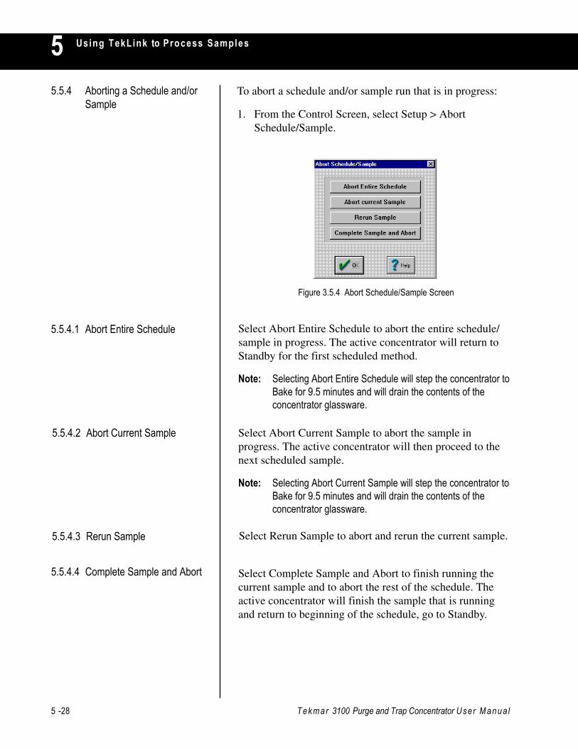
5 -28 Tekmar 3100 Purge and Trap Concentrator User Manua l
Using TekLink to Process Samples55.5.4 Aborting a Schedule and/or
SampleTo abort a schedule and/or sample run that is in progress:
1. From the Control Screen, select Setup > AbortSchedule/Sample.
Figure 3.5.4 Abort Schedule/Sample Screen
5.5.4.1 Abort Entire Schedule
5.5.4.2 Abort Current Sample
5.5.4.3 Rerun Sample
5.5.4.4 Complete Sample and Abort
Select Abort Entire Schedule to abort the entire schedule/sample in progress. The active concentrator will return toStandby for the first scheduled method.
Note: Selecting Abort Entire Schedule will step the concentrator toBake for 9.5 minutes and will drain the contents of theconcentrator glassware.
Select Abort Current Sample to abort the sample inprogress. The active concentrator will then proceed to thenext scheduled sample.
Note: Selecting Abort Current Sample will step the concentrator toBake for 9.5 minutes and will drain the contents of theconcentrator glassware.
Select Rerun Sample to abort and rerun the current sample.
Select Complete Sample and Abort to finish running thecurrent sample and to abort the rest of the schedule. Theactive concentrator will finish the sample that is runningand return to beginning of the schedule, go to Standby.
Tekmar 3100 Purge and Trap Concentrator User Manua l 5 -29
Using TekLink to Process Samples 55.6 TekLink Error
MessagesThe following are TekLink dialog messages regarding errorsthat may occur. Please refer to your concentrator userdocumentation for descriptions of error messages specific to3100 operation.
5.6.1 Maximum FailsafeExceeded on Heater X*
5.6.2 Minimum Failsafe Exceededon Heater X
5.6.3 Open Thermocouple onHeater X
5.6.5 Power Fail
5.6.8 System Reset
5.6.6 Sample Method Does NotMatch Schedule Position
5.6.7 Self-Test Failure on HeaterX
5.6.9 Setpoint Not Reached onHeater X
The displayed heater could not reach its setpoint.
* X denotes a particular heater name.
The displayed heater did not pass self test.
The concentrator was reset by either the reset button on theconcentrator or in TekLink. The concentrator will gothrough self test after a reset.
The current schedule and the method it is set to use do notmatch. Example: An AQUATek 70 method being run onposition 0 (which is the front panel and not theautosampler); or a 3100 method being run on position 12which is not a front-panel method.
Power to the concentrator was dropped while it was on.
Displayed heater is disconnected or has opened up.
Displayed heater has dropped below its minimumallowable temperature.
Displayed heater has exceeded its maximum allowabletemperature.
5.6.4 Out-of-Range Error WhileScheduling
The value (sample vial position number) entered in eitherthe Start or Stop fields in the Schedule Control screen areincorrect for the chosen method. When you click OK, thevalues return to their defaults.
5 -30 Tekmar 3100 Purge and Trap Concentrator User Manua l
Using TekLink to Process Samples55.6.10 AQUATek ASM Not
Responding
5.6.11 AQUATek Sensor Error
5.6.12 AQUATek Heater Error
Make sure the AQUATek 70 and autosampler are turned onand that they are recognized by and configured in TekLink.An AQUATek 70 method may be loaded in TekLink whilethere is no AQUATek 70.
This error will occur when the base temperature of the hotwater tank inside the AQUATek 70 does not reach temp.The sensor board screw on top of the hot water tank may beloose or the sensor board may need replacement.
Note: Please refer to the AQUATek 70 user manual for furtherinstruction.
This error will occur when the secondary temperature ofthe hot water tank inside the AQUATek 70 continues to tryand reach temp for over 20 minutes. The sensor boardscrew on top of the hot water tank may be loose, the sensorboard may need replacement, or the hot water tankassembly may need replacement.
Note: Please refer to the AQUATek 70 user manual for furtherinstruction.

USING THE HAND-HELD CONTROLLERTO PROCESS SAMPLES
Chapter 6

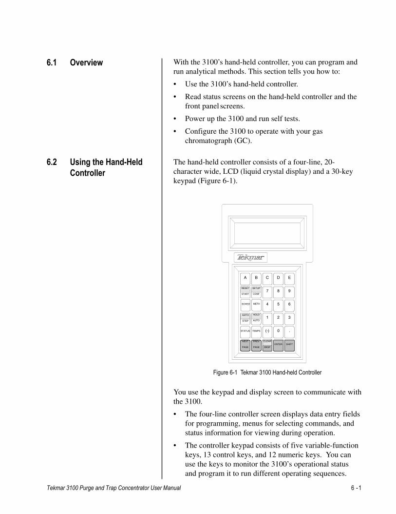
Tekmar 3100 Purge and Trap Concentrator User Manual 6 -1
Using the Hand-held to Process Samples 66.1 Overview
6.2 Using the Hand-HeldController
You use the keypad and display screen to communicate withthe 3100.
• The four-line controller screen displays data entry fieldsfor programming, menus for selecting commands, andstatus information for viewing during operation.
• The controller keypad consists of five variable-functionkeys, 13 control keys, and 12 numeric keys. You canuse the keys to monitor the 3100’s operational statusand program it to run different operating sequences.
A B C
7
1
(-)
4
D
8
2
0
5
E
9
3
.
6
ENTER
STATUS TEMPS
START CONF
PREV
PAGE
SCHED METH
HOLD
AUTO
GOTO
STEP
SHIFT
RESET SETUP
NEXT
PAGE
CLEAR
BKSP
Figure 6-1 Tekmar 3100 Hand-held Controller
With the 3100’s hand-held controller, you can program andrun analytical methods. This section tells you how to:
• Use the 3100’s hand-held controller.
• Read status screens on the hand-held controller and thefront panel screens.
• Power up the 3100 and run self tests.
• Configure the 3100 to operate with your gaschromatograph (GC).
The hand-held controller consists of a four-line, 20-character wide, LCD (liquid crystal display) and a 30-keykeypad (Figure 6-1).
6 -2 Tekmar 3100 Purge and Trap Concentrator User Manual
Using the Hand-held to Process Samples6The hand-held controller comes with an interface cable.
1. Locate the jack on the bottom of the front panel displayhousing.
2. Plug the end of the cable into the front panel jack.
3. Plug the other end of the cable into the jack on thebottom of the controller.
Keys in the first row (labeled A - E) are used to selectoptions from a screen menu. Their function varies,depending on the options displayed on the current screen.For example:
• From the Setup screen, press the A key to displaysystem information.
• From the Reset screen, press the A key to abort aschedule.
6.2.1 Installing the Hand-heldController
6.2.2 Variable Function Keys
6.2.3 Control Keys The control keys consist of:
• Action keys (RESET, START, AUTO, HOLD, STEP,and GO TO). These keys start, control, and stopanalytical runs.
• Screen keys (SETUP, CONF, STATUS, SCHED,METH, and TEMPS). These keys display screens thatenable you to define operating parameters, set upschedules, and review status and temperature.
• Special keys (NEXT/PREV PAGE, BKSP, CLEAR, andSHIFT). These keys let you scroll through displays ormanipulate and save data.
Keys with two-part labels have two functions. To use thefunction on the lower half of the label, press the controlkey. To use the function on the upper half of the label, pressand hold SHIFT while you press the control key.
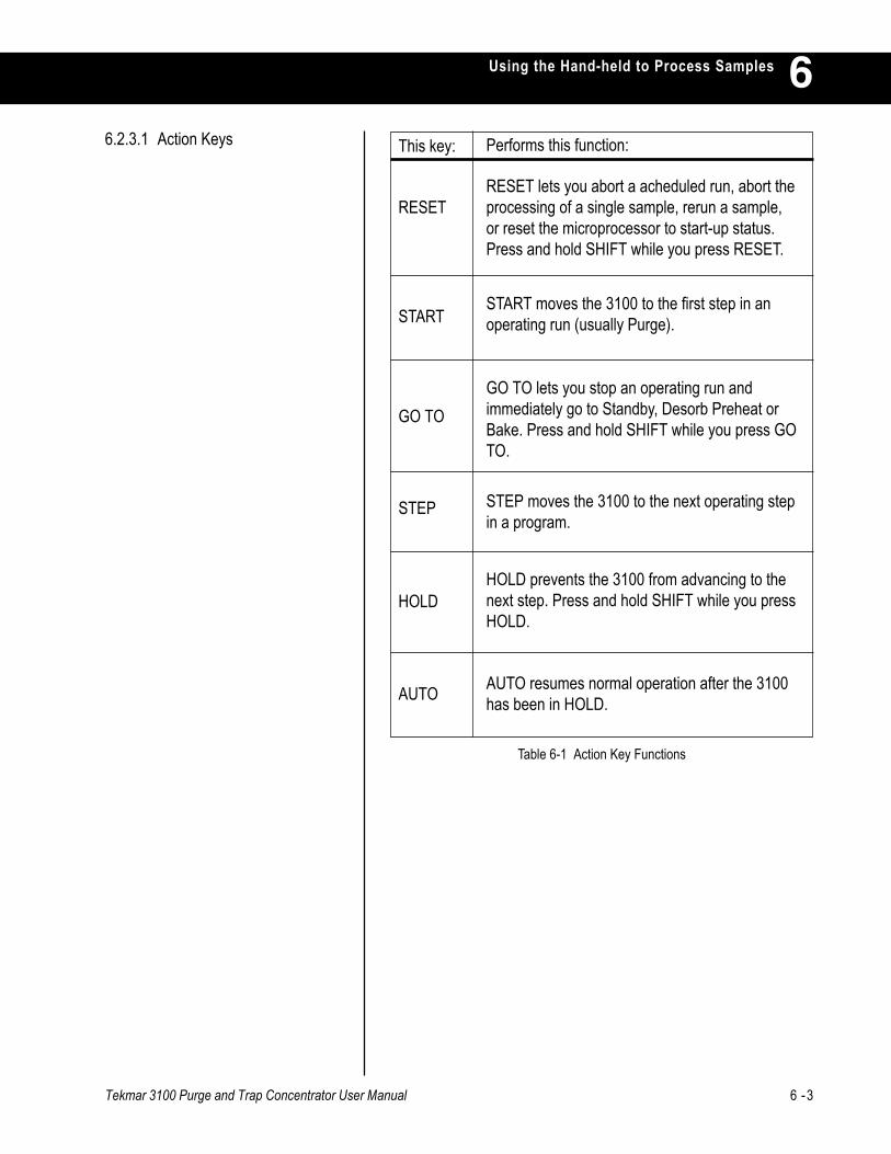
Tekmar 3100 Purge and Trap Concentrator User Manual 6 -3
Using the Hand-held to Process Samples 66.2.3.1 Action Keys
Table 6-1 Action Key Functions
This key: Performs this function:
RESET
START
GO TO
STEP
HOLD
AUTO
RESET lets you abort a acheduled run, abort theprocessing of a single sample, rerun a sample,or reset the microprocessor to start-up status.Press and hold SHIFT while you press RESET.
START moves the 3100 to the first step in anoperating run (usually Purge).
GO TO lets you stop an operating run andimmediately go to Standby, Desorb Preheat orBake. Press and hold SHIFT while you press GOTO.
STEP moves the 3100 to the next operating stepin a program.
HOLD prevents the 3100 from advancing to thenext step. Press and hold SHIFT while you pressHOLD.
AUTO resumes normal operation after the 3100has been in HOLD.
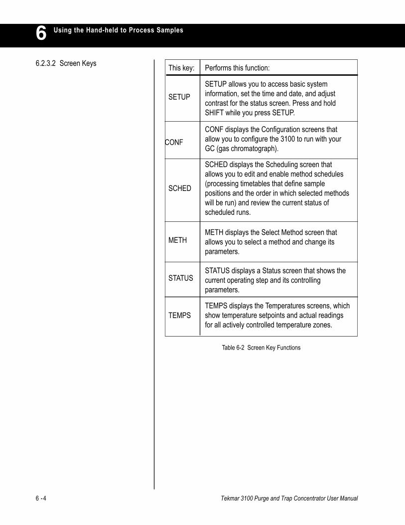
6 -4 Tekmar 3100 Purge and Trap Concentrator User Manual
Using the Hand-held to Process Samples66.2.3.2 Screen Keys
Table 6-2 Screen Key Functions
METH
SETUP
CONF
SCHED
STATUS
TEMPS
SETUP allows you to access basic systeminformation, set the time and date, and adjustcontrast for the status screen. Press and holdSHIFT while you press SETUP.
CONF displays the Configuration screens thatallow you to configure the 3100 to run with yourGC (gas chromatograph).
SCHED displays the Scheduling screen thatallows you to edit and enable method schedules(processing timetables that define samplepositions and the order in which selected methodswill be run) and review the current status ofscheduled runs.
METH displays the Select Method screen thatallows you to select a method and change itsparameters.
STATUS displays a Status screen that shows thecurrent operating step and its controllingparameters.
TEMPS displays the Temperatures screens, whichshow temperature setpoints and actual readingsfor all actively controlled temperature zones.
This key: Performs this function:
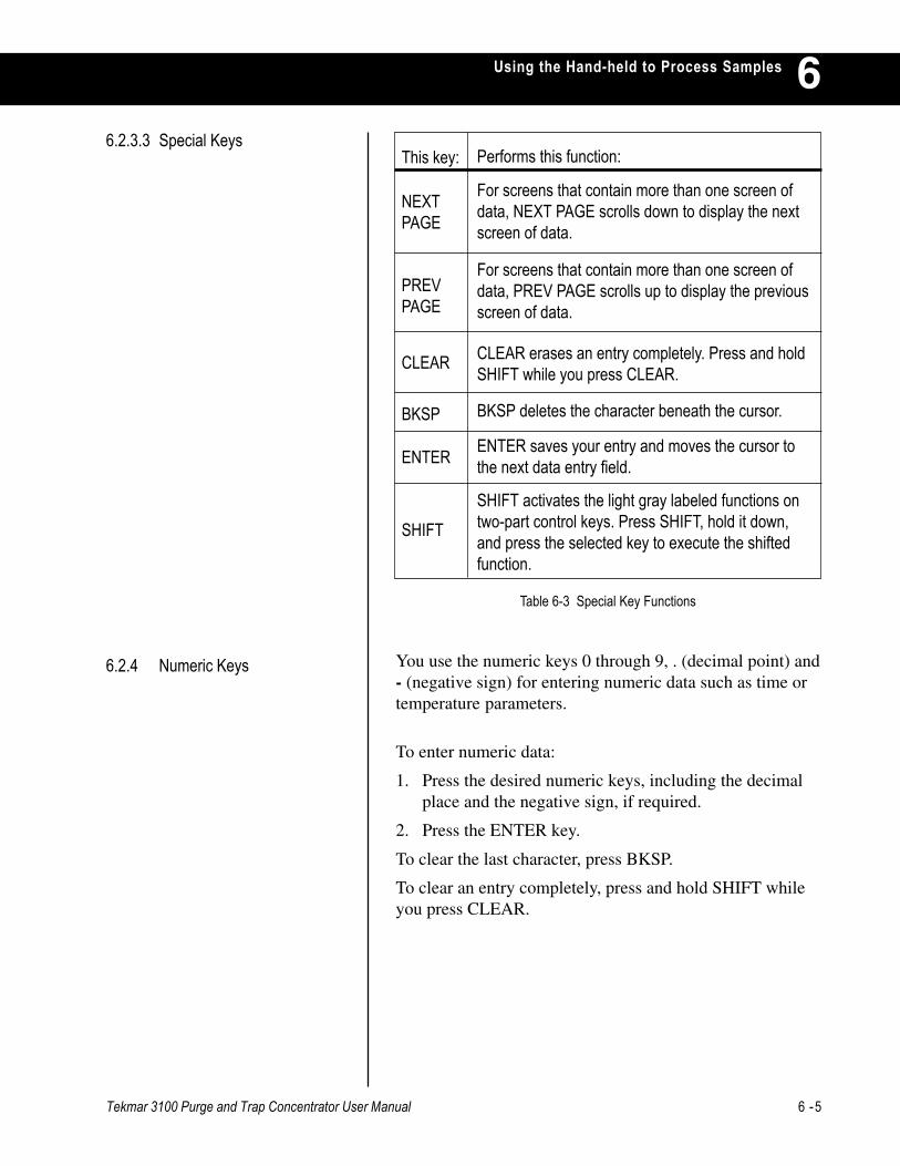
Tekmar 3100 Purge and Trap Concentrator User Manual 6 -5
Using the Hand-held to Process Samples 66.2.3.3 Special Keys
Table 6-3 Special Key Functions
NEXTPAGE
PREVPAGE
CLEAR
BKSP
ENTER
SHIFT
For screens that contain more than one screen ofdata, NEXT PAGE scrolls down to display the nextscreen of data.
For screens that contain more than one screen ofdata, PREV PAGE scrolls up to display the previousscreen of data.
CLEAR erases an entry completely. Press and holdSHIFT while you press CLEAR.
BKSP deletes the character beneath the cursor.
ENTER saves your entry and moves the cursor tothe next data entry field.
SHIFT activates the light gray labeled functions ontwo-part control keys. Press SHIFT, hold it down,and press the selected key to execute the shiftedfunction.
This key: Performs this function:
You use the numeric keys 0 through 9, . (decimal point) and- (negative sign) for entering numeric data such as time ortemperature parameters.
To enter numeric data:
1. Press the desired numeric keys, including the decimalplace and the negative sign, if required.
2. Press the ENTER key.
To clear the last character, press BKSP.
To clear an entry completely, press and hold SHIFT whileyou press CLEAR.
6.2.4 Numeric Keys

6 -6 Tekmar 3100 Purge and Trap Concentrator User Manual
Using the Hand-held to Process Samples6The 3100 hand-held controller uses several types ofdisplay:
• A two-line, front panel status display.
• Status screens (on the hand-held controller).
• Menu screens (on the hand-held controller).
• Action screens (on the hand-held controller).
• Data entry screens (on the hand-held controller).
During each operating step of a run, the front panel screencontinuously displays two lines of status information.
When the temperature setpoint is the controlling parameterfor the step, the front panel screen displays the informationillustrated in Figure 6-2.
6.3 Using Screens
6.3.1 Front Panel StatusDisplay
6.3.1.1 Temperature ParameterDisplay
Figure 6-2 Front Panel Status Screen
Each part of the screen above is labeled with a number. Seethe matching numbers below to find out more about eachpart of the screen.
1 The name of the operating step appears on the first line, at the leftmargin.
2 The number of the currently-active method appears on the first line, at theright margin. If the 3100 is running a method schedule, this positionshows the currently-active method number and currently-active sampleposition. For example, M7P04 indicates that method 7is running on sample position 4.
3 The name of the heated or cooled zone and its current measuredtemperature appear at the left on the second line. The display updatesthis value continuously as the temperature changes.
4 The temperature setpoint for the step appears at the right on the secondline.
Standby1 2M01
MCS3 97-> 4230C
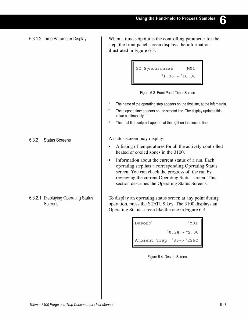
Tekmar 3100 Purge and Trap Concentrator User Manual 6 -7
Using the Hand-held to Process Samples 6When a time setpoint is the controlling parameter for thestep, the front panel screen displays the informationillustrated in Figure 6-3.
6.3.1.2 Time Parameter Display
Figure 6-3 Front Panel Timer Screen
1 The name of the operating step appears on the first line, at the left margin.2 The elapsed time appears on the second line. The display updates this
value continuously.3 The total time setpoint appears at the right on the second line.
6.3.2 Status Screens
GC Synchronize1 M01
21.00 - 310.00
To display an operating status screen at any point duringoperation, press the STATUS key. The 3100 displays anOperating Status screen like the one in Figure 6-4.
6.3.2.1 Displaying Operating StatusScreens
Figure 6-4 Desorb Screen
Desorb1 2M01
30.38 - 42.00
Ambient Trap 535-> 6225C
A status screen may display:
• A listing of temperatures for all the actively-controlledheated or cooled zones in the 3100.
• Information about the current status of a run. Eachoperating step has a corresponding Operating Statusscreen. You can check the progress of the run byreviewing the current Operating Status screen. Thissection describes the Operating Status Screens.
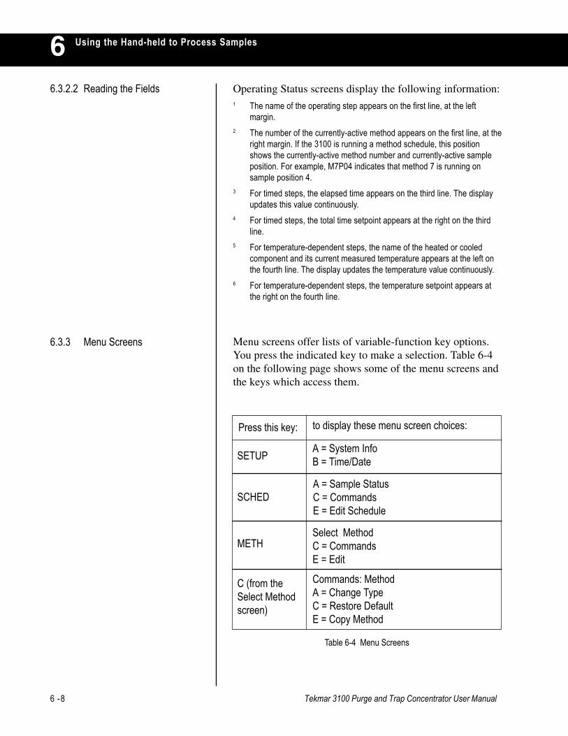
6 -8 Tekmar 3100 Purge and Trap Concentrator User Manual
Using the Hand-held to Process Samples6
Table 6-4 Menu Screens
Operating Status screens display the following information:1 The name of the operating step appears on the first line, at the left
margin.2 The number of the currently-active method appears on the first line, at the
right margin. If the 3100 is running a method schedule, this positionshows the currently-active method number and currently-active sampleposition. For example, M7P04 indicates that method 7 is running onsample position 4.
3 For timed steps, the elapsed time appears on the third line. The displayupdates this value continuously.
4 For timed steps, the total time setpoint appears at the right on the thirdline.
5 For temperature-dependent steps, the name of the heated or cooledcomponent and its current measured temperature appears at the left onthe fourth line. The display updates the temperature value continuously.
6 For temperature-dependent steps, the temperature setpoint appears atthe right on the fourth line.
6.3.2.2 Reading the Fields
6.3.3 Menu Screens Menu screens offer lists of variable-function key options.You press the indicated key to make a selection. Table 6-4on the following page shows some of the menu screens andthe keys which access them.
to display these menu screen choices:Press this key:
SETUP
SCHED
METH
C (from theSelect Methodscreen)
A = System InfoB = Time/Date
A = Sample StatusC = CommandsE = Edit Schedule
Select MethodC = CommandsE = Edit
Commands: MethodA = Change TypeC = Restore DefaultE = Copy Method
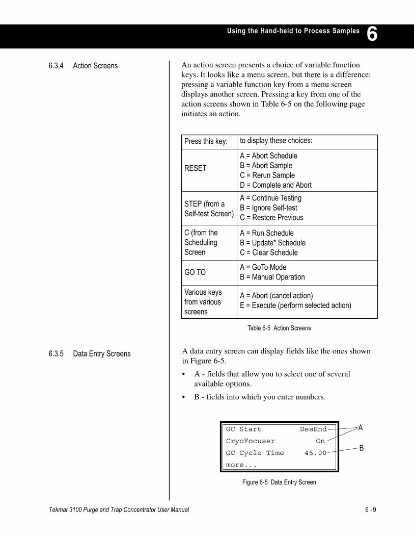
Tekmar 3100 Purge and Trap Concentrator User Manual 6 -9
Using the Hand-held to Process Samples 6
Table 6-5 Action Screens
Figure 6-5 Data Entry Screen
A data entry screen can display fields like the ones shownin Figure 6-5.
• A - fields that allow you to select one of severalavailable options.
• B - fields into which you enter numbers.
6.3.5 Data Entry Screens
A
B
GC Start DesEnd
CryoFocuser On
GC Cycle Time 45.00
more...
A = Abort ScheduleB = Abort SampleC = Rerun SampleD = Complete and AbortA = Continue TestingB = Ignore Self-testC = Restore Previous
A = Run ScheduleB = Update* ScheduleC = Clear Schedule
A = GoTo ModeB = Manual Operation
to display these choices:Press this key:
RESET
STEP (from aSelf-test Screen)
C (from theSchedulingScreen
GO TO
Various keysfrom variousscreens
A = Abort (cancel action)E = Execute (perform selected action)
An action screen presents a choice of variable functionkeys. It looks like a menu screen, but there is a difference:pressing a variable function key from a menu screendisplays another screen. Pressing a key from one of theaction screens shown in Table 6-5 on the following pageinitiates an action.
6.3.4 Action Screens

6 -10 Tekmar 3100 Purge and Trap Concentrator User Manual
Using the Hand-held to Process Samples66.3.5.1 Option Selection Fields To review available options and select one:
1. If the cursor is on the option to be changed, press anynumber key to toggle the status field. Each time youpress a number key, the field displays the next availableoption. When the desired option is displayed, pressENTER to select it. The cursor moves to the next line.
2. If the cursor is not on the option you wish to change,press ENTER to move the cursor, one line at a time.When the cursor reaches the bottom of the screen, pressENTER to move it back to the top of the screen.
3. Press any number key to toggle the status field, asdescribed in step 1.
To enter a number into a data entry field:
1. If the cursor is on the desired field, type the appropriatenumbers in the field; then press ENTER.
2. If the cursor is not on the desired field, press ENTER tomove the cursor, one line at a time. When the cursorreaches the bottom of the screen, press ENTER to moveit back to the top of the screen.
3. Type the numbers in the field; then press ENTER.
To begin 3100 operation:
1. Turn on the 3100. (The switch is on the rear panel.) The3100 loads program data into memory, performsinitialization tasks, and briefly displays the message,"Initialization successful" on the front panel screens.
2. The screen on the front panel (Figure 6-6) shows thedate and time of the last power loss.
6.3.5.2 Data Entry Fields
6.4 Getting Started
Figure 6-6 Initial Front Panel Screen
The screen on the controller (Figure 6-7 on the followingpage) shows the same date and time.
Power Fail
12/20/98 10:12:14
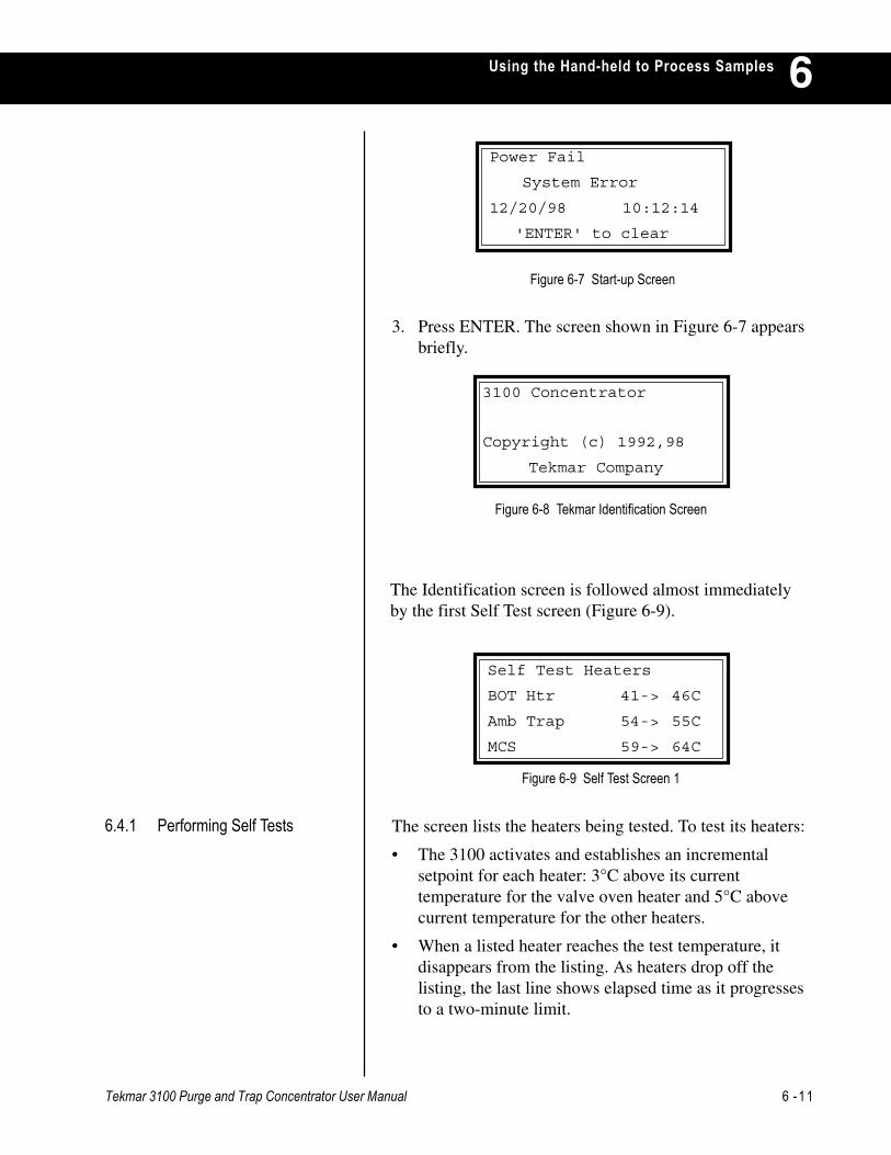
Tekmar 3100 Purge and Trap Concentrator User Manual 6 -11
Using the Hand-held to Process Samples 6
Figure 6-7 Start-up Screen
3. Press ENTER. The screen shown in Figure 6-7 appearsbriefly.
Figure 6-8 Tekmar Identification Screen
6.4.1 Performing Self Tests
The Identification screen is followed almost immediatelyby the first Self Test screen (Figure 6-9).
Figure 6-9 Self Test Screen 1
The screen lists the heaters being tested. To test its heaters:
• The 3100 activates and establishes an incrementalsetpoint for each heater: 3°C above its currenttemperature for the valve oven heater and 5°C abovecurrent temperature for the other heaters.
• When a listed heater reaches the test temperature, itdisappears from the listing. As heaters drop off thelisting, the last line shows elapsed time as it progressesto a two-minute limit.
3100 Concentrator
Copyright (c) 1992,98
Tekmar Company
Power Fail
System Error
12/20/98 10:12:14
'ENTER' to clear
Self Test Heaters
BOT Htr 41-> 46C
Amb Trap 54-> 55C
MCS 59-> 64C
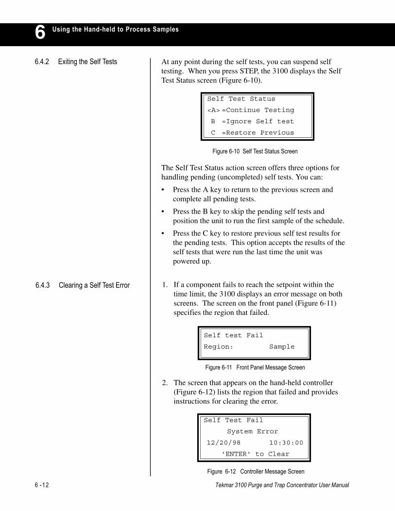
6 -12 Tekmar 3100 Purge and Trap Concentrator User Manual
Using the Hand-held to Process Samples66.4.2 Exiting the Self Tests At any point during the self tests, you can suspend self
testing. When you press STEP, the 3100 displays the SelfTest Status screen (Figure 6-10).
The Self Test Status action screen offers three options forhandling pending (uncompleted) self tests. You can:
• Press the A key to return to the previous screen andcomplete all pending tests.
• Press the B key to skip the pending self tests andposition the unit to run the first sample of the schedule.
• Press the C key to restore previous self test results forthe pending tests. This option accepts the results of theself tests that were run the last time the unit waspowered up.
Figure 6-10 Self Test Status Screen
6.4.3 Clearing a Self Test Error
Figure 6-11 Front Panel Message Screen
2. The screen that appears on the hand-held controller(Figure 6-12) lists the region that failed and providesinstructions for clearing the error.
Figure 6-12 Controller Message Screen
Self Test Status
<A> =Continue Testing
B =Ignore Self test
C =Restore Previous
Self test Fail
Region: Sample
Self Test Fail
System Error
12/20/98 10:30:00
'ENTER' to Clear
1. If a component fails to reach the setpoint within thetime limit, the 3100 displays an error message on bothscreens. The screen on the front panel (Figure 6-11)specifies the region that failed.
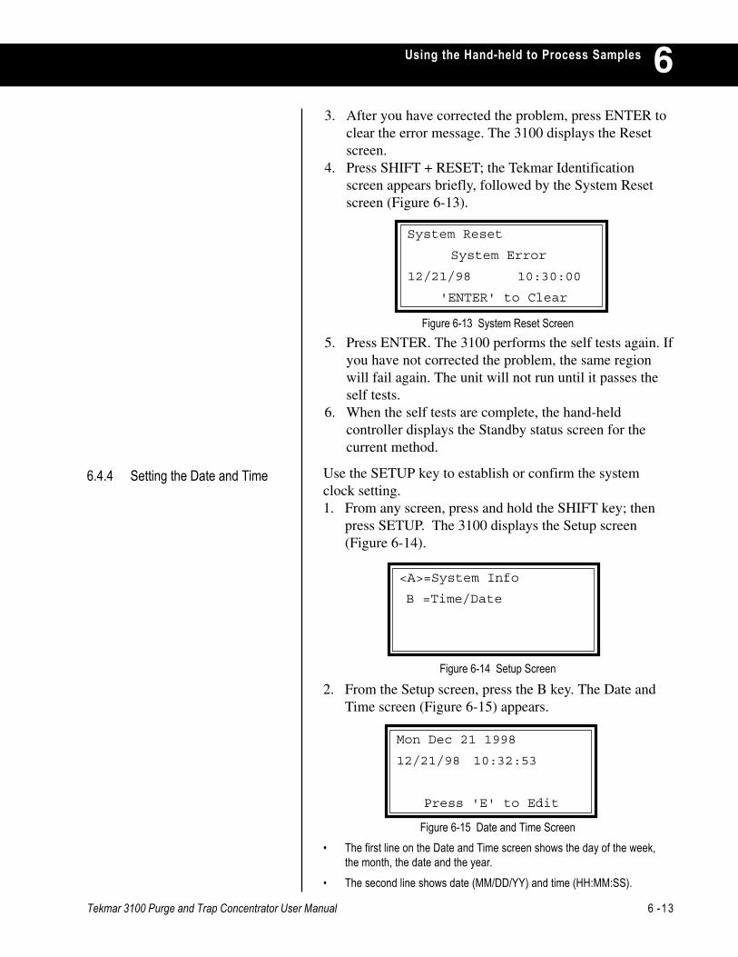
Tekmar 3100 Purge and Trap Concentrator User Manual 6 -13
Using the Hand-held to Process Samples 63. After you have corrected the problem, press ENTER to
clear the error message. The 3100 displays the Resetscreen.
4. Press SHIFT + RESET; the Tekmar Identificationscreen appears briefly, followed by the System Resetscreen (Figure 6-13).
Figure 6-13 System Reset Screen5. Press ENTER. The 3100 performs the self tests again. If
you have not corrected the problem, the same regionwill fail again. The unit will not run until it passes theself tests.
6. When the self tests are complete, the hand-heldcontroller displays the Standby status screen for thecurrent method.
Figure 6-14 Setup Screen
2. From the Setup screen, press the B key. The Date andTime screen (Figure 6-15) appears.
Figure 6-15 Date and Time Screen
6.4.4 Setting the Date and Time
Mon Dec 21 1998
12/21/98 10:32:53
Press 'E' to Edit
<A>=System Info
B =Time/Date
System Reset
System Error
12/21/98 10:30:00
'ENTER' to Clear
Use the SETUP key to establish or confirm the systemclock setting.1. From any screen, press and hold the SHIFT key; then
press SETUP. The 3100 displays the Setup screen(Figure 6-14).
• The first line on the Date and Time screen shows the day of the week,the month, the date and the year.
• The second line shows date (MM/DD/YY) and time (HH:MM:SS).
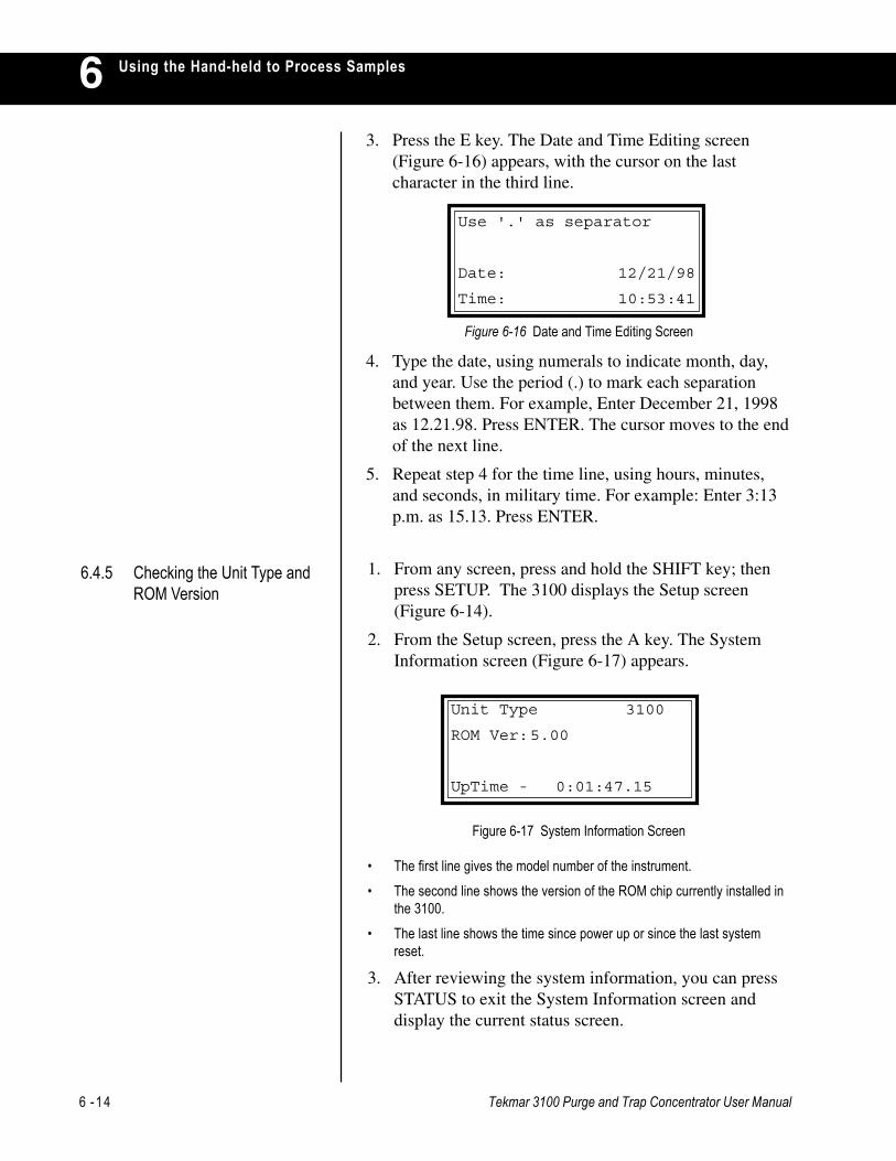
6 -14 Tekmar 3100 Purge and Trap Concentrator User Manual
Using the Hand-held to Process Samples63. Press the E key. The Date and Time Editing screen
(Figure 6-16) appears, with the cursor on the lastcharacter in the third line.
4. Type the date, using numerals to indicate month, day,and year. Use the period (.) to mark each separationbetween them. For example, Enter December 21, 1998as 12.21.98. Press ENTER. The cursor moves to the endof the next line.
5. Repeat step 4 for the time line, using hours, minutes,and seconds, in military time. For example: Enter 3:13p.m. as 15.13. Press ENTER.
Figure 6-17 System Information Screen
• The first line gives the model number of the instrument.• The second line shows the version of the ROM chip currently installed in
the 3100.• The last line shows the time since power up or since the last system
reset.
3. After reviewing the system information, you can pressSTATUS to exit the System Information screen anddisplay the current status screen.
6.4.5 Checking the Unit Type andROM Version
Figure 6-16 Date and Time Editing Screen
Use '.' as separator
Date: 12/21/98
Time: 10:53:41
Unit Type 3100
ROM Ver:5.00
UpTime - 0:01:47.15
1. From any screen, press and hold the SHIFT key; thenpress SETUP. The 3100 displays the Setup screen(Figure 6-14).
2. From the Setup screen, press the A key. The SystemInformation screen (Figure 6-17) appears.
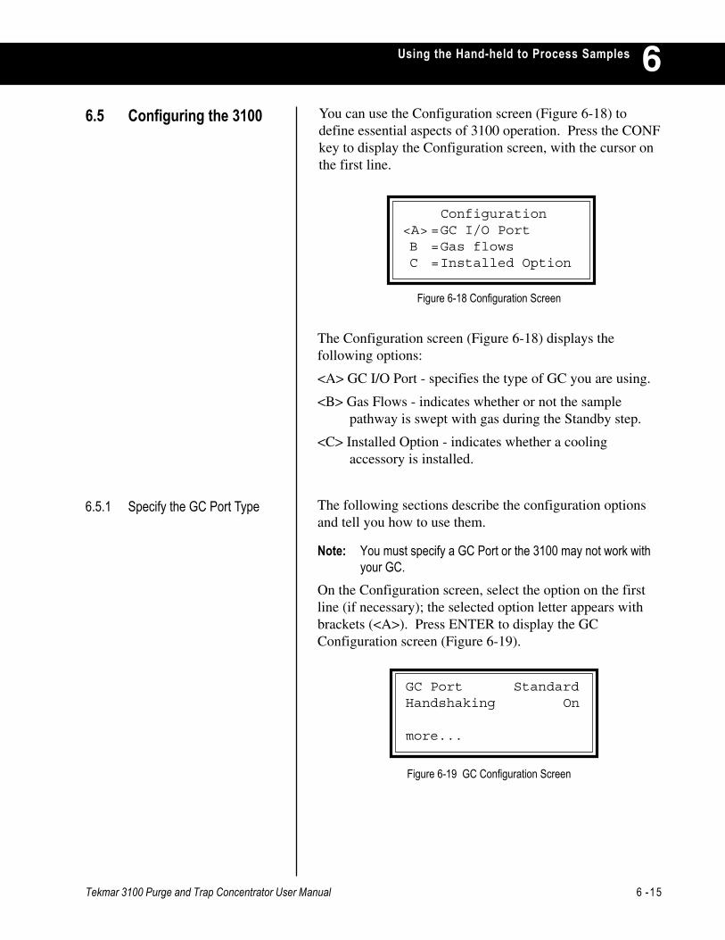
Tekmar 3100 Purge and Trap Concentrator User Manual 6 -15
Using the Hand-held to Process Samples 6
6.5.1 Specify the GC Port Type
You can use the Configuration screen (Figure 6-18) todefine essential aspects of 3100 operation. Press the CONFkey to display the Configuration screen, with the cursor onthe first line.
6.5 Configuring the 3100
The Configuration screen (Figure 6-18) displays thefollowing options:
<A> GC I/O Port - specifies the type of GC you are using.
<B> Gas Flows - indicates whether or not the samplepathway is swept with gas during the Standby step.
<C> Installed Option - indicates whether a coolingaccessory is installed.
The following sections describe the configuration optionsand tell you how to use them.
Note: You must specify a GC Port or the 3100 may not work withyour GC.
On the Configuration screen, select the option on the firstline (if necessary); the selected option letter appears withbrackets (<A>). Press ENTER to display the GCConfiguration screen (Figure 6-19).
Figure 6-18 Configuration Screen
Figure 6-19 GC Configuration Screen
GC Port StandardHandshaking On
more...
Configuration<A> =GC I/O PortB =Gas flowsC =Installed Option

6 -16 Tekmar 3100 Purge and Trap Concentrator User Manual
Using the Hand-held to Process Samples6
The instructions shipped with your 3100-to-GC interfacecable tells you how to specify the type of GC you are using.If you do not have these instructions, refer to table 3-2 onthe next pages. Find your GC and the corresponding GCPort on the table and follow the steps below. If you do nothave interface cable instructions and you cannot find yourGC on the table, see the next section.
1. If your GC is Standard, press ENTER to select Standardas the GC Port. The 3100 is now configured to operatewith your GC. (Most GCs operate using Standard as theGC Port.) Skip the next steps and go to Section 6.5.2,Specify Handshaking.
2. If your GC is not standard, select User. Press anynumber key to select User as the GC Port, then press theNEXT PAGE key to display the Special GC Typescreen (Figure 6-20).
3. Enter the User GC Type number. If you do not knowwhich number to enter, find your GC on Table 6-7.Enter the number that is in the GC Type Numbercolumn.
From the GC Configuration screen, you can specify thetype of GC you are using. The first line displays GC Port, aclassification based on the input-output characteristics ofthe GC as it interacts with the 3100.
Note: The GC is interfaced to the 3100 via an interface cable,which runs from the GC to the 25-pin connector on the3100’s GC I/O card. Table 6-6 lists the available GC Portoptions.
Table 6-6 Available GC Port Types
A standard GC (all input and output signalsfrom a standard GC are normally-open relayclosures or TTL active-low signals)
The GC supplies or accepts all normally-closed relay closures, all TTL active-highsignals, a combination of normally-open andnormally-closed relays or a combination ofTTL active-low and TTL active-high signals.
Standard
User
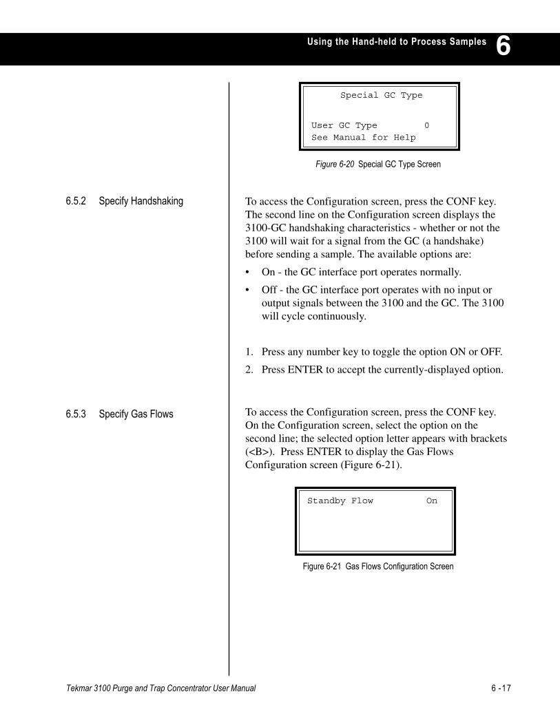
Tekmar 3100 Purge and Trap Concentrator User Manual 6 -17
Using the Hand-held to Process Samples 6
Figure 6-20 Special GC Type Screen
Special GC Type
User GC Type 0
See Manual for Help
To access the Configuration screen, press the CONF key.The second line on the Configuration screen displays the3100-GC handshaking characteristics - whether or not the3100 will wait for a signal from the GC (a handshake)before sending a sample. The available options are:
• On - the GC interface port operates normally.
• Off - the GC interface port operates with no input oroutput signals between the 3100 and the GC. The 3100will cycle continuously.
1. Press any number key to toggle the option ON or OFF.
2. Press ENTER to accept the currently-displayed option.
To access the Configuration screen, press the CONF key.On the Configuration screen, select the option on thesecond line; the selected option letter appears with brackets(<B>). Press ENTER to display the Gas FlowsConfiguration screen (Figure 6-21).
6.5.3 Specify Gas Flows
Figure 6-21 Gas Flows Configuration Screen
Standby Flow On
6.5.2 Specify Handshaking
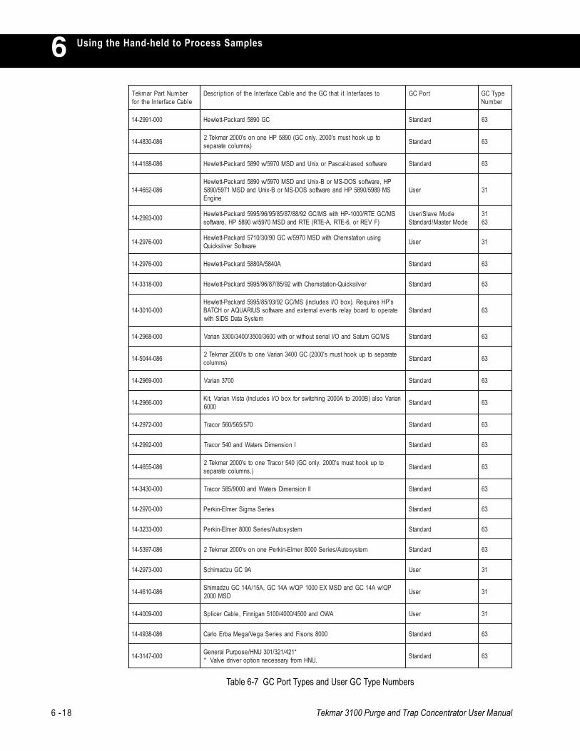
6 -18 Tekmar 3100 Purge and Trap Concentrator User Manual
Using the Hand-held to Process Samples6rebmuNtraPramkeTelbaCecafretnIehtrof
otsecafretnItitahtCGehtdnaelbaCecafretnIehtfonoitpircseD troPCG epyTCGrebmuN
000-1992-41 CG0985drakcaP-ttelweH dradnatS 36
680-0384-41 otpukoohtsums'0002.ylnoCG(0985PHenonos'0002ramkeT2)snmulocetarapes dradnatS 36
680-8814-41 erawtfosdesab-lacsaProxinUdnaDSM0795/w0985drakcaP-ttelweH dradnatS 36
680-2564-41PH,erawtfosSOD-SMroB-xinUdnaDSM0795/w0985drakcaP-ttelweHSM9895/0985PHdnaerawtfosSOD-SMroB-xinUdnaDSM1795/0985
enignEresU 13
000-3992-41 SM/CGETR/0001-PHhtiwSM/CG29/88/78/58/59/69/5995drakcaP-ttelweH)FVERro,6-ETR,A-ETR(ETRdnaDSM0795/w0985PH,erawtfos
edoMevalS/resUedoMretsaM/dradnatS
1336
000-6792-41 gnisunoitatsmehChtiwDSM0795/wCG09/03/0175drakcaP-ttelweHerawtfoSrevliskciuQ resU 13
000-6792-41 A0485/A0885drakcaP-ttelweH dradnatS 36
000-8133-41 revliskciuQ-noitatsmehChtiw29/58/78/69/5995drakcaP-ttelweH dradnatS 36
000-0103-41s'PHseriuqeR.)xobO/Isedulcni(SM/CG29/39/58/5995drakcaP-ttelweH
etarepootdraobyalerstnevelanretxednaerawtfosSUIRAUQAroHCTABmetsySataDSDIShtiw
dradnatS 36
000-8692-41 SM/CGnrutaSdnaO/Ilairestuohtiwrohtiw0063/0053/0043/0033nairaV dradnatS 36
680-4405-41 etarapesotpukoohtsums'0002(CG0043nairaVenoots'0002ramkeT2)snmuloc dradnatS 36
000-9692-41 0073nairaV dradnatS 36
000-6692-41 nairaVosla)B0002otA0002gnihctiwsrofxobO/Isedulcni(atsiVnairaV,tiK0006 dradnatS 36
000-2792-41 075/565/065rocarT dradnatS 36
000-2992-41 InoisnemiDsretaWdna045rocarT dradnatS 36
680-5564-41 otpukoohtsums'0002.ylnoCG(045rocarTenoots'0002ramkeT2).snmulocetarapes dradnatS 36
000-0343-41 IInoisnemiDsretaWdna0009/585rocarT dradnatS 36
000-0792-41 seireSamgiSremlE-nikreP dradnatS 36
000-3323-41 metsysotuA/seireS0008remlE-nikreP dradnatS 36
680-7935-41 metsysotuA/seireS0008remlE-nikrePenonos'0002ramkeT2 dradnatS 36
000-3792-41 A9CGuzdamihcS resU 13
680-0164-41 PQ/wA41CGdnaDSMXE0001PQ/wA41CG,A51/A41CGuzdamihSDSM0002 resU 13
000-9004-41 AWOdna0054/0004/0015naginniF,elbaCrecilpS resU 13
680-8394-41 0008snosiFdnaseireSageV/ageMabrEolraC dradnatS 36
000-7413-41 *124/123/103UNH/esopruPlareneG.UNHmorfyrassecennoitporevirdevlaV* dradnatS 36
Table 6-7 GC Port Types and User GC Type Numbers
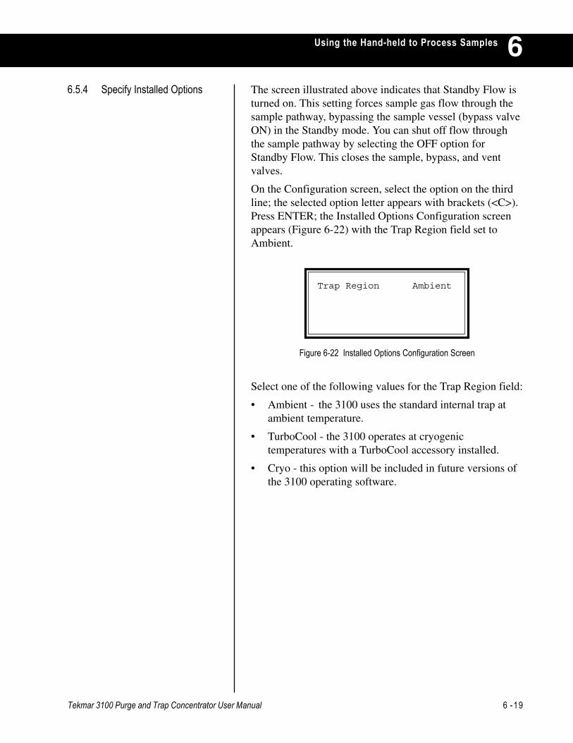
Tekmar 3100 Purge and Trap Concentrator User Manual 6 -19
Using the Hand-held to Process Samples 6The screen illustrated above indicates that Standby Flow isturned on. This setting forces sample gas flow through thesample pathway, bypassing the sample vessel (bypass valveON) in the Standby mode. You can shut off flow throughthe sample pathway by selecting the OFF option forStandby Flow. This closes the sample, bypass, and ventvalves.
On the Configuration screen, select the option on the thirdline; the selected option letter appears with brackets (<C>).Press ENTER; the Installed Options Configuration screenappears (Figure 6-22) with the Trap Region field set toAmbient.
6.5.4 Specify Installed Options
Figure 6-22 Installed Options Configuration Screen
Select one of the following values for the Trap Region field:
• Ambient - the 3100 uses the standard internal trap atambient temperature.
• TurboCool - the 3100 operates at cryogenictemperatures with a TurboCool accessory installed.
• Cryo - this option will be included in future versions ofthe 3100 operating software.
Trap Region Ambient
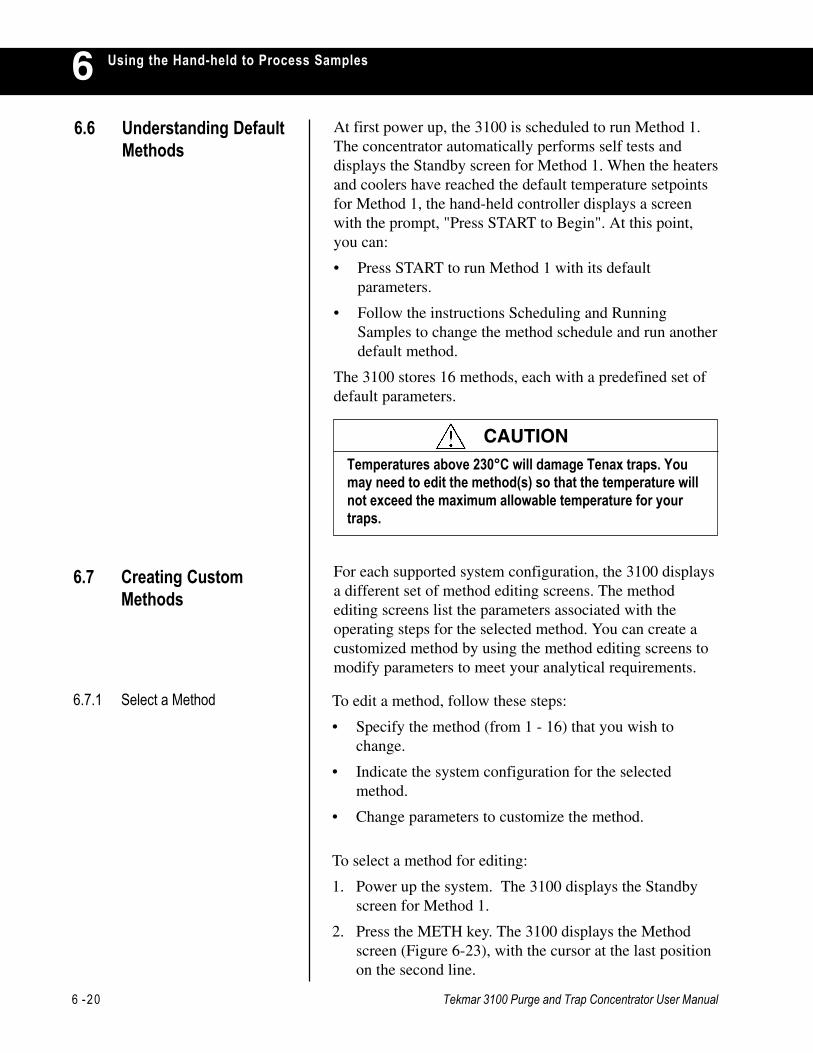
6 -20 Tekmar 3100 Purge and Trap Concentrator User Manual
Using the Hand-held to Process Samples6
To edit a method, follow these steps:
• Specify the method (from 1 - 16) that you wish tochange.
• Indicate the system configuration for the selectedmethod.
• Change parameters to customize the method.
To select a method for editing:
1. Power up the system. The 3100 displays the Standbyscreen for Method 1.
2. Press the METH key. The 3100 displays the Methodscreen (Figure 6-23), with the cursor at the last positionon the second line.
6.7.1 Select a Method
At first power up, the 3100 is scheduled to run Method 1.The concentrator automatically performs self tests anddisplays the Standby screen for Method 1. When the heatersand coolers have reached the default temperature setpointsfor Method 1, the hand-held controller displays a screenwith the prompt, "Press START to Begin". At this point,you can:
• Press START to run Method 1 with its defaultparameters.
• Follow the instructions Scheduling and RunningSamples to change the method schedule and run anotherdefault method.
The 3100 stores 16 methods, each with a predefined set ofdefault parameters.
6.6 Understanding DefaultMethods
Temperatures above 230°C will damage Tenax traps. Youmay need to edit the method(s) so that the temperature willnot exceed the maximum allowable temperature for yourtraps.
CAUTION
For each supported system configuration, the 3100 displaysa different set of method editing screens. The methodediting screens list the parameters associated with theoperating steps for the selected method. You can create acustomized method by using the method editing screens tomodify parameters to meet your analytical requirements.
6.7 Creating CustomMethods

Tekmar 3100 Purge and Trap Concentrator User Manual 6 -21
Using the Hand-held to Process Samples 6
6.7.2 Indicate the SystemConfiguration
Figure 6-24 Method Commands Screen
Commands: Method 1
<A>=Change Type
C =Restore Method
E =Copy Method
• Line 2 shows the number of the active method (1through 16). The active method (the startup default) isMethod 1.
• Line 3 indicates the system configuration for thecurrently-active method. The default type for Method 1is 3100.
3. At the Method field, enter the number of the method tobe changed; then press ENTER.
To indicate the system configuration to be supported by theselected method:
1. Press the C key to display the Method Commandsscreen (Figure 6-24).
Select Method
Method 1
Type 3100
<C>=Commands E=Edit
Figure 6-23 Method Screen
2. Press the A key (or press ENTER when A is highlightedwith <> brackets) to display the Change Method Typescreen (Figure 6-25), with the cursor on the third line.
Figure 6-25 Change Method Type Screen
Change Method Type
Method 1
Type 3100
<A>=Abort E=Execute
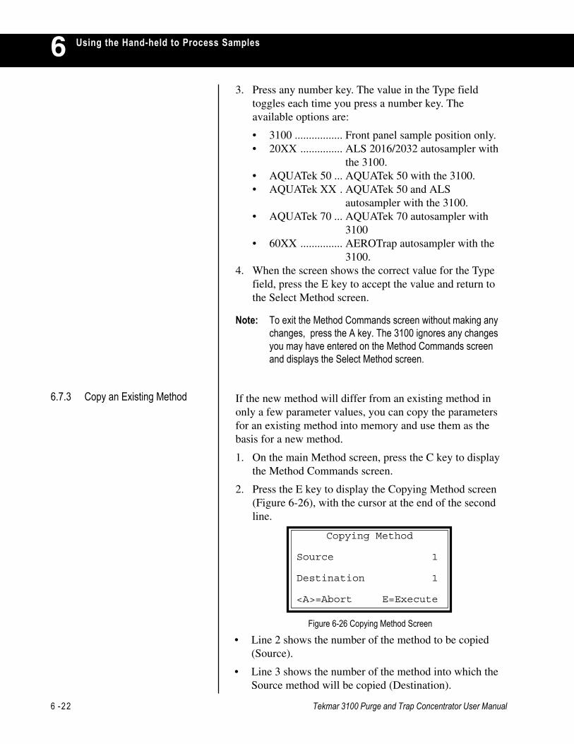
6 -22 Tekmar 3100 Purge and Trap Concentrator User Manual
Using the Hand-held to Process Samples63. Press any number key. The value in the Type field
toggles each time you press a number key. Theavailable options are:
• 3100 ................. Front panel sample position only.• 20XX ............... ALS 2016/2032 autosampler with
the 3100.• AQUATek 50 ... AQUATek 50 with the 3100.• AQUATek XX . AQUATek 50 and ALS
autosampler with the 3100.• AQUATek 70 ... AQUATek 70 autosampler with
3100• 60XX ............... AEROTrap autosampler with the
3100.4. When the screen shows the correct value for the Type
field, press the E key to accept the value and return tothe Select Method screen.
Note: To exit the Method Commands screen without making anychanges, press the A key. The 3100 ignores any changesyou may have entered on the Method Commands screenand displays the Select Method screen.
6.7.3 Copy an Existing Method If the new method will differ from an existing method inonly a few parameter values, you can copy the parametersfor an existing method into memory and use them as thebasis for a new method.
1. On the main Method screen, press the C key to displaythe Method Commands screen.
2. Press the E key to display the Copying Method screen(Figure 6-26), with the cursor at the end of the secondline.
Figure 6-26 Copying Method Screen
Copying Method
Source 1
Destination 1
<A>=Abort E=Execute
• Line 2 shows the number of the method to be copied(Source).
• Line 3 shows the number of the method into which theSource method will be copied (Destination).
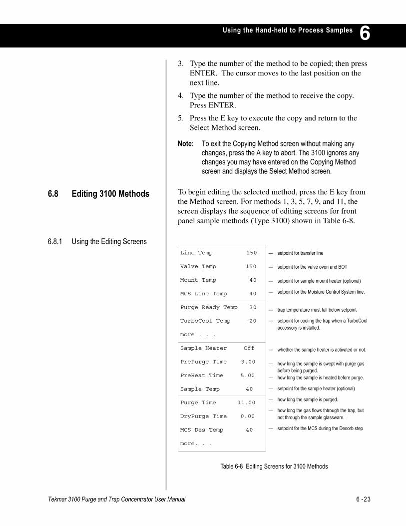
Tekmar 3100 Purge and Trap Concentrator User Manual 6 -23
Using the Hand-held to Process Samples 63. Type the number of the method to be copied; then press
ENTER. The cursor moves to the last position on thenext line.
4. Type the number of the method to receive the copy.Press ENTER.
5. Press the E key to execute the copy and return to theSelect Method screen.
Note: To exit the Copying Method screen without making anychanges, press the A key to abort. The 3100 ignores anychanges you may have entered on the Copying Methodscreen and displays the Select Method screen.
6.8 Editing 3100 Methods To begin editing the selected method, press the E key fromthe Method screen. For methods 1, 3, 5, 7, 9, and 11, thescreen displays the sequence of editing screens for frontpanel sample methods (Type 3100) shown in Table 6-8.
6.8.1 Using the Editing Screens
Table 6-8 Editing Screens for 3100 Methods
— setpoint for transfer line
— setpoint for the valve oven and BOT
— setpoint for sample mount heater (optional)
— setpoint for the Moisture Control System line.
— trap temperature must fall below setpoint
— setpoint for cooling the trap when a TurboCoolaccessory is installed.
— whether the sample heater is activated or not.
— how long the sample is swept with purge gasbefore being purged.
— how long the sample is heated before purge.
— setpoint for the sample heater (optional)
— how long the sample is purged.
— how long the gas flows thtrough the trap, butnot through the sample glassware.
— setpoint for the MCS during the Desorb step
Line Temp 150
Valve Temp 150
Mount Temp 40
MCS Line Temp 40
Purge Ready Temp 30
TurboCool Temp -20
more . . .
Sample Heater Off
PrePurge Time 3.00
PreHeat Time 5.00
Sample Temp 40
Purge Time 11.00
DryPurge Time 0.00
MCS Des Temp 40
more. . .
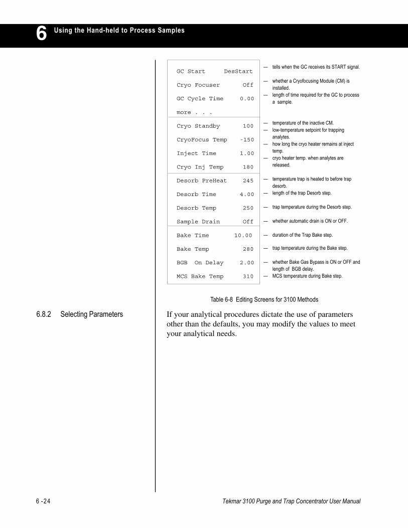
6 -24 Tekmar 3100 Purge and Trap Concentrator User Manual
Using the Hand-held to Process Samples6
GC Start DesStart
Cryo Focuser Off
GC Cycle Time 0.00
more . . .
Cryo Standby 100
CryoFocus Temp -150
Inject Time 1.00
Cryo Inj Temp 180
Desorb PreHeat 245
Desorb Time 4.00
Desorb Temp 250
Sample Drain Off
Bake Time 10.00
Bake Temp 280
BGB On Delay 2.00
MCS Bake Temp 310
— tells when the GC receives its START signal.
— whether a Cryofocusing Module (CM) isinstalled.
— length of time required for the GC to processa sample.
— temperature of the inactive CM.— low-temperature setpoint for trapping
analytes.— how long the cryo heater remains at inject
temp.— cryo heater temp. when analytes are
released.
— temperature trap is heated to before trapdesorb.
— length of the trap Desorb step.
— trap temperature during the Desorb step.
— whether automatic drain is ON or OFF.
— duration of the Trap Bake step.
— trap temperature during the Bake step.
— whether Bake Gas Bypass is ON or OFF andlength of BGB delay.
— MCS temperature during Bake step.
If your analytical procedures dictate the use of parametersother than the defaults, you may modify the values to meetyour analytical needs.
6.8.2 Selecting Parameters
Table 6-8 Editing Screens for 3100 Methods
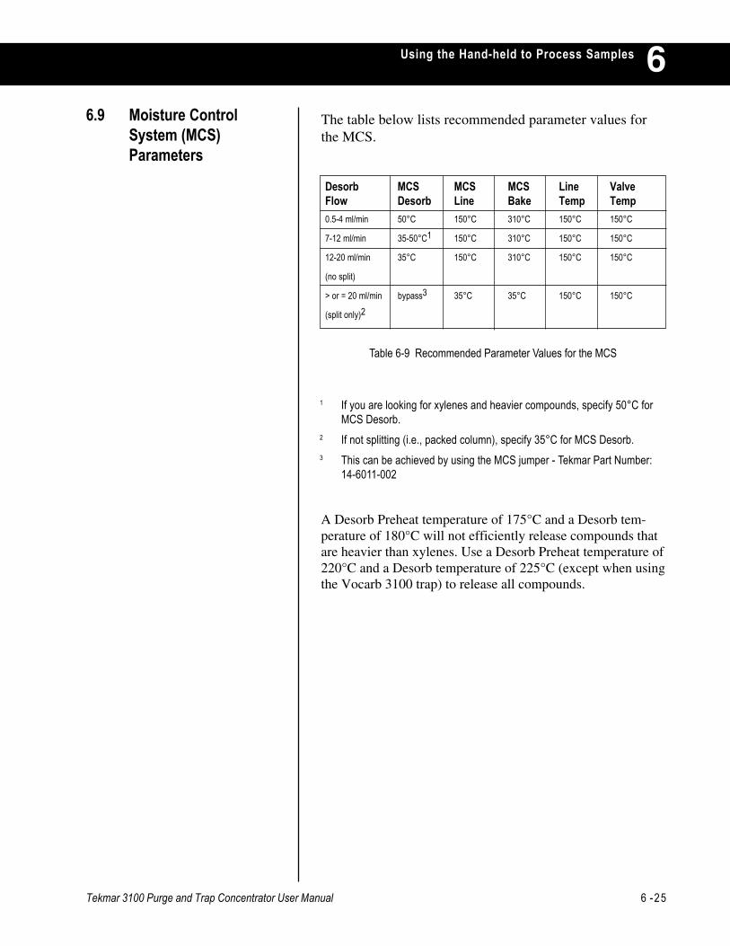
Tekmar 3100 Purge and Trap Concentrator User Manual 6 -25
Using the Hand-held to Process Samples 6
A Desorb Preheat temperature of 175°C and a Desorb tem-perature of 180°C will not efficiently release compounds thatare heavier than xylenes. Use a Desorb Preheat temperature of220°C and a Desorb temperature of 225°C (except when usingthe Vocarb 3100 trap) to release all compounds.
The table below lists recommended parameter values forthe MCS.
Table 6-9 Recommended Parameter Values for the MCS
1 If you are looking for xylenes and heavier compounds, specify 50°C forMCS Desorb.
2 If not splitting (i.e., packed column), specify 35°C for MCS Desorb.3 This can be achieved by using the MCS jumper - Tekmar Part Number:
14-6011-002
6.9 Moisture ControlSystem (MCS)Parameters
Desorb MCS MCS MCS Line ValveFlow Desorb Line Bake Temp Temp0.5-4 ml/min 50°C 150°C 310°C 150°C 150°C
7-12 ml/min 35-50°C1 150°C 310°C 150°C 150°C
12-20 ml/min 35°C 150°C 310°C 150°C 150°C
(no split)
> or = 20 ml/min bypass3 35°C 35°C 150°C 150°C
(split only)2

6 -26 Tekmar 3100 Purge and Trap Concentrator User Manual
Using the Hand-held to Process Samples6You can undo changes made to default parameters for anymethod.
1. Press METH on the keypad.
2. At the the method field, enter the number of the methodwith the defaults you wish to restore; then pressENTER.
3. Press the C key to display the Method Commandsscreen (Figure 6-27).
Figure 6-27 Method Command Screen
4. Press the C key to display the Restore Default screen(Figure 6-28).
Figure 6-28 Restore Default Screen
5. Press the E key to execute the command. The 3100:
• Erases any custom parameter values that have beenprogrammed forthe current method.
• Restores the default values.
• Returns to the Select Method screen display.
Note: To exit the Restore Default screen without making anychanges, press the A key to abort. The 3100 ignores anychanges or commands you may have entered on theRestore Default screen and displays the Select Methodscreen.
6.10 Restoring DefaultParameters
Commands: Method 1
<A>=Change Type
C =Restore Default
E =Copy Method
Restore Default
Method 1
<A>=Abort E=Execute

Tekmar 3100 Purge and Trap Concentrator User Manual 6 -27
Using the Hand-held to Process Samples 6You must set up a method schedule, or processingtimetable, to “tell” the 3100 which method(s) will be run onwhich sample(s). This is true regardless of whether you areusing a single position unit or a unit with an autosamplerattached. When you use the 3100 without an autosampler,you can specify the number and sequence of methods to berun on a single sample. When you use the 3100 with one ormore autosamplers, a method schedule defines:
· The method(s) to be run.
· Start and stop positions for each method.
· A sequential order for each sample to be run.
· The number of runs per sample.
Briefly, here is how you can create and activate a methodschedule:
1. Establish a desired method schedule.
2. Enter the desired schedule parameters.
3. Run the schedule.
Before you set up your method schedule, consider:
· The number and type of samples to be run.
· The method required for each sample.
· The preferred sequence in which to run the samples.
6.11 Creating a NewSchedule
6.11.1 Establishing a MethodSchedule
1. From any screen, press the SCHED key. The Schedulingscreen (Figure 6-29) appears.
Figure 6-29 Scheduling Screen
6.11.2 Entering ScheduleParameters
2. At the Scheduling screen, press E to display theSchedule Editing screen (Figure 6-30), with the cursoron the first position in the Start column.
Scheduling <A>=Sample Status C =Commands E =Edit Schedule

6 -28 Tekmar 3100 Purge and Trap Concentrator User Manual
Using the Hand-held to Process Samples6
Figure 6-30 Schedule Editing Screen
Each row specifies:
• The number of a method to be run (in the Methcolumn). The default method is Method 1.
• The position of the first sample (in the Start column)and the last sample (in the Stop column) to be runaccording to the specified method. The default samplestart and stop positions are 0, which is the numberassigned to the sample that is run on the 3100.
• The number of times each sample will be run (in theRPS, Runs per Sample column).
You can change the schedule in several ways. You can:
• Specify a different method to be run by changing thenumber in the Meth column.
• Specify different start and stop positions for a givenmethod by changing the numbers in the Start and Stopcolumns.
• Indicate that a sample position should be run more thanonce by changing the number in the RPS column.
To make changes in the method schedule:
1. Type the desired parameters into each field, pressingENTER after each entry. The cursor moves to the nextfield in the row. When you reach the end of a row, thecursor moves to the first field in the next row.
2. If necessary, press NEXT PAGE to display succeedingscreens of Schedule Edit parameters: Rows 4-6, 7-9,and 10-12.
3. When you have entered the complete schedule, pressthe SCHED key to return to the Scheduling screen.
6.11.2.1Review Default ScheduleParameters
The schedule in figure 6-30 shows the default scheduleparameters for the 3100. The Schedule Editing screen hasfour columns and up to 12 rows.
6.11.2.2Changing the Schedule
Start Stop Meth RPS1) 0 0 1 12) 0 0 0 13) 0 0 0 1

Tekmar 3100 Purge and Trap Concentrator User Manual 6 -29
Using the Hand-held to Process Samples 6Figure 6-31 shows a typical schedule, for running two Type20XX methods (2 and 4) on specified sample positions.
Figure 6-31 Schedule Editing Screen
To enter this schedule:
1. On the first row, enter 1, 8, 2, and 2 in their respectivecolumns. These entries specify that:
• The samples in positions 1 through 8 will be runaccording to Method 2, with each sample being runtwice.
• Method 2 is a Type 20XX method; if you scheduleposition 8 for a method that has no position 8 (aType 3100 method, for example), the 3100 displaysan error message when you try to run the schedule.
2. On the second row, enter 9, 12, 4, and 1 in theirrespective columns. These entries specify that samples9 through 12 will be run according to Method 4, witheach sample being run through the method once.
To enter this schedule:1. On the first row, enter 0, 0, 3, and 3 in their respective
columns. These entries specify that Method 3 (a 3100method) will be run on the 3100’s front panel sample.The sample will be run three times.
Note: If you are setting up a schedule to be run on anautosampler, be sure to specify methods that are the correcttype for your system configuration. If you have ROM (read-only memory) version 2.10 or greater, a stop position that isless then the start position will cause the 3100 to run sample#1 on the autosampler after the last sample is run.
6.11.2.3Sample Schedules
Figure 6-32 Sample Schedule Editing Screen
Start Stop Meth RPS1) 1 8 2 22) 9 12 4 13) 0 0 0 1
Start Stop Meth RPS1) 0 0 3 32) 0 0 0 13) 0 0 0 1

6 -30 Tekmar 3100 Purge and Trap Concentrator User Manual
Using the Hand-held to Process Samples6To run a schedule:
1. From the Scheduling screen, press the C key to displaythe Schedule Commands screen (Figure 6-33).
Figure 6-33 Schedule Commands Screen
2. Press A (Run Schedule). The 3100 starts the currentschedule and displays the Standby Status screen (Figure6-34) for the first sample.
You can edit a schedule in the middle of a run. From theoperating step Status screen press SCHED.1. Allow the current schedule to run its course. After the
3100 completes the currently-running schedule, itautomatically builds and runs the new schedule (the oneyou just entered). ~or~
2. Build the new schedule and run it from the beginning byfollowing these steps:a. Press the SCHED key to display the Scheduling
screen.b. Press C to display the Schedule Commands screen.c. Press A (Run Schedule). The new schedule is built,
and the 3100 goes into Standby as it prepares tostart running the new schedule.~or~
3. If your changes affect only those parts of the schedulethat have not yet been run, combine the new schedulewith the old and continue to run from your currentposition.a. Press the SCHED key to display the Scheduling
screen.b. Press C to display the Schedule Commands screen.c. Press B (Update* Schedule). The 3100 incorporates
the new schedule into the old and continues to run.
Figure 6-34 Standby Status Screen
6.11.3 Running the Schedule
6.11.4 Changing the ScheduleDuring a Run
Schedule Commands<A>=Run ScheduleB =Update ScheduleC =Clear Schedule
Standby M1P01BOT Htr 97->200CMCS 30->100CXferLine 150->250C
During Standby, the 3100 establishes initial conditions.

Tekmar 3100 Purge and Trap Concentrator User Manual 6 -31
Using the Hand-held to Process Samples 66.11.5 Restoring the Default
ScheduleTo restore the default schedule (Method 1 for a front panelsample on the 3100), press C (Clear Schedule) on theSchedule Commands screen..
While the 3100 is operating, it shows a status screenindicating the current operating step and its activeparameters. The operating steps vary, depending on the typeof method you are using. This example shows the operatingsteps for running default Method 1.
6.12 Running a Sample
When all Standby setpoints have been reached, the PurgeReady screen (Figure 6-35) appears.
Figure 6-35 Purge Ready Screen
6.12.1 Purge Ready
Note: If you have not yet leak checked the 3100, do so before youstart a run.
Purge Ready waits for a start signal from the user (via theSTART key on the keypad), or from an accessory, beforeproceeding to the next step.
• To begin a run, press START on the terminal keypad.
The 3100 proceeds to the next step in the scheduledmethod. As the 3100 goes through a run, it displays a statusscreen for each step.
Note: You can always display a status screen by pressingSTATUS on the keypad. For example, if you are editingone method while running another, you can press STATUSto review conditions for the cur-rently active operating step.You can also review this information on the 3100’s frontpanel display.
Purge Ready M1P00
Press START to Begin
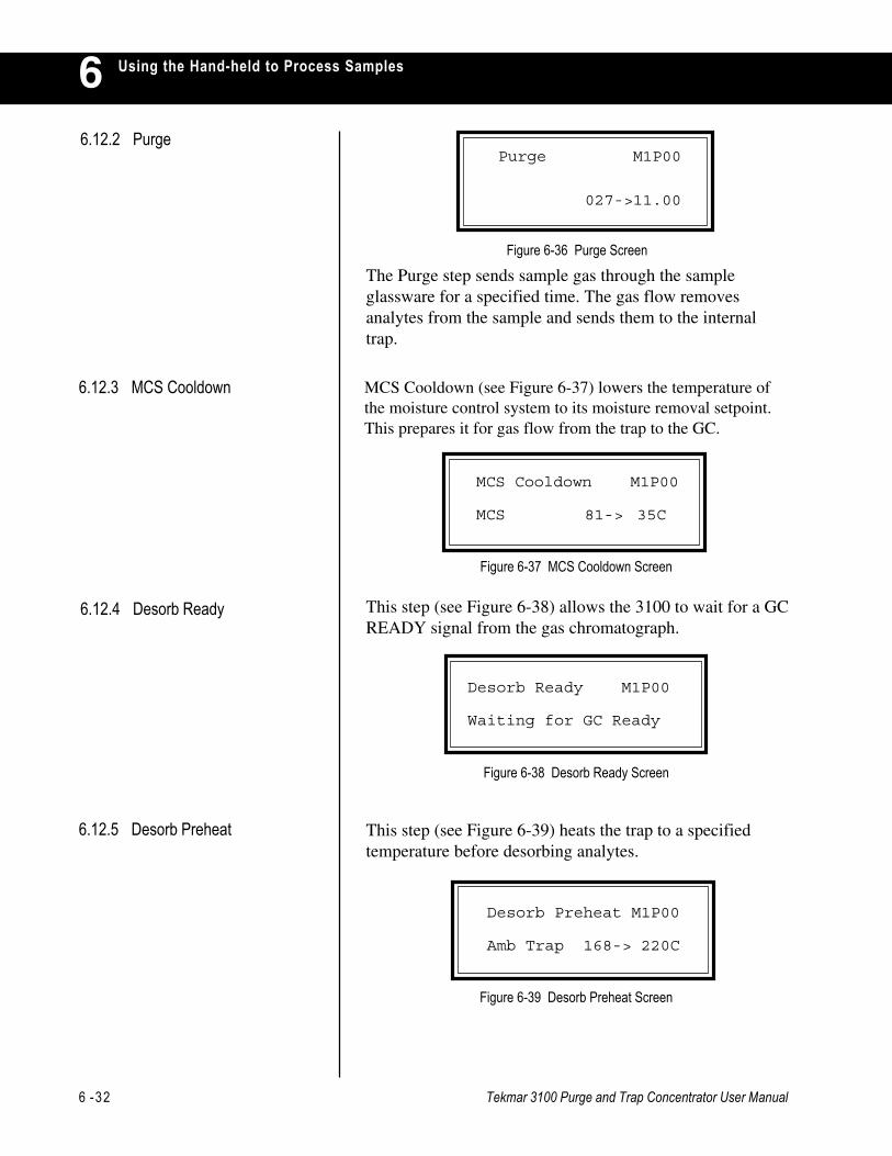
6 -32 Tekmar 3100 Purge and Trap Concentrator User Manual
Using the Hand-held to Process Samples6
Figure 6-38 Desorb Ready Screen
This step (see Figure 6-39) heats the trap to a specifiedtemperature before desorbing analytes.
Figure 6-39 Desorb Preheat Screen
6.12.3 MCS Cooldown
6.12.5 Desorb Preheat
MCS Cooldown (see Figure 6-37) lowers the temperature ofthe moisture control system to its moisture removal setpoint.This prepares it for gas flow from the trap to the GC.
Figure 6-37 MCS Cooldown Screen
This step (see Figure 6-38) allows the 3100 to wait for a GCREADY signal from the gas chromatograph.
6.12.4 Desorb Ready
MCS Cooldown M1P00
MCS 81-> 35C
Desorb Ready M1P00
Waiting for GC Ready
Desorb Preheat M1P00
Amb Trap 168-> 220C
6.12.2 Purge
Figure 6-36 Purge Screen
The Purge step sends sample gas through the sampleglassware for a specified time. The gas flow removesanalytes from the sample and sends them to the internaltrap.
Purge M1P00
027->11.00
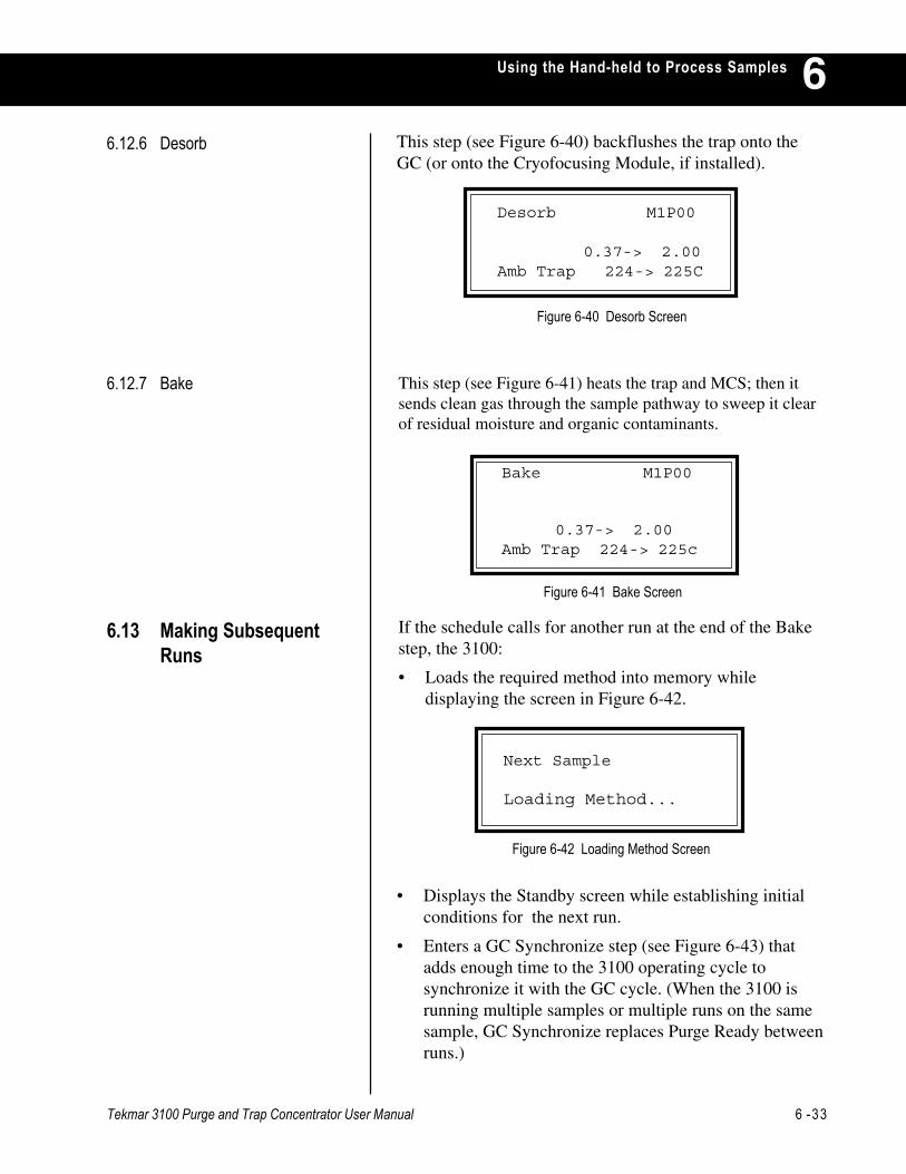
Tekmar 3100 Purge and Trap Concentrator User Manual 6 -33
Using the Hand-held to Process Samples 6This step (see Figure 6-40) backflushes the trap onto theGC (or onto the Cryofocusing Module, if installed).
Figure 6-40 Desorb Screen
6.12.6 Desorb
Desorb M1P00
0.37-> 2.00Amb Trap 224-> 225C
Figure 6-41 Bake Screen
• Displays the Standby screen while establishing initialconditions for the next run.
• Enters a GC Synchronize step (see Figure 6-43) thatadds enough time to the 3100 operating cycle tosynchronize it with the GC cycle. (When the 3100 isrunning multiple samples or multiple runs on the samesample, GC Synchronize replaces Purge Ready betweenruns.)
6.12.7 Bake This step (see Figure 6-41) heats the trap and MCS; then itsends clean gas through the sample pathway to sweep it clearof residual moisture and organic contaminants.
If the schedule calls for another run at the end of the Bakestep, the 3100:
• Loads the required method into memory whiledisplaying the screen in Figure 6-42.
6.13 Making SubsequentRuns
Figure 6-42 Loading Method Screen
Bake M1P00
0.37-> 2.00Amb Trap 224-> 225c
Next Sample
Loading Method...

6 -34 Tekmar 3100 Purge and Trap Concentrator User Manual
Using the Hand-held to Process Samples6
Figure 6-45 Go To Commands Screen
At any point during a run, you can display a ManualOperations screen that allows you to:
• Toggle the position of the drain valve to control the flowof liquid draining from the sample.
• Toggle the position of the vent valve to control backpressure on the sample gas feed.
To display the Manual Operations screen:
1. Press SHIFT-GO TO. The 3100 displays the screen inFigure 6-45.
Figure 6-46 Manual Operations Screen
6.14 Controlling ManualOperations
2. Press B. The Manual Operations screen (Figure 6-46.)
Goto Commands
A =Goto Mode <B>=Manual Operation
<A>=Drain B =Feed Pressure
Manual Operations
Figure 6-43 GC Synchronize Screen
• Instructs the autosampler to activate its multi-positionvalve and switch to the correct sample position whiledisplaying the screen in Figure 6-44.
Figure 6-44 MPV Positioning Screen
GC Synchronize
0.00 -> 5.00
20XX Position M2P03
2016 MPV Position:3
Tekmar 3100 Purge and Trap Concentrator User Manual 6 -35
Using the Hand-held to Process Samples 6The drain valve allows the sample glassware to be emptied.When it is open, liquid and gas can be forced out of thesample glassware into the drain system and out the backpanel drain. If your ROM (read-only memory) version isprior to 2.10, you can drain only during Standby, PurgeReady, and Desorb.
To toggle the drain open or closed:
1. From the Manual Operations screen, press A to open thedrain valve.
2. The letter D flashes in the upper right of the screen, infront of the method number.
3. To close the drain valve and turn off the flashing D,repeat step 1.
6.14.1 Manual Drain
6.15 Interrupting a Run
6.14.2 Feed Pressure Setting The vent valve allows sample gas to exit the samplepathway through a front panel vent. When it is closed,pressure builds up in the sample pathway. This is used toset the feed pressure (it eliminates TPC effects). If yourROM (read-only memory) version is prior to 2.10, you canselect feed pressure only during Standby and Purge Ready.
To toggle the vent open or closed:
1. From the Manual Operations screen, press B to closethe vent valve.
2. P flashes in the upper right of the screen, in front of themethod number.
3. To open the vent valve and turn off the flashing P,repeat step 1.
At any point during a run, you can use control keys on theterminal keypad to:
• Change the normal sequence of operating steps,
• Abort part or all of the scheduled runs, or
• Review the current status of a method schedule.

6 -36 Tekmar 3100 Purge and Trap Concentrator User Manual
Using the Hand-held to Process Samples6
Figure 6-48 Go To Mode Screen
Figure 6-47 Go To Commands Screen
a. Press A at the Goto commands screen to display theGoto Mode screen (Figure 6-48).
b. Press A to display the Reset screen (Figure 6-49).Follow the instructions in the next section Reset theSchedule to select one of the Reset options andreturn to the Standby step.
c. Press B to for the Desorb Preheat operating step.This prepares the 3100 to desorb the internal trap.
d. Press C to go to the Bake operating step. This cleansout the concentrator.
• Also, to change the the normal progression through anoperating sequence, press Shift-Hold. The concentratorgoes into HOLD mode and does not advance to the nextoperating step. While the system is in HOLD, (1) the letter H flashes in the upper right corner of thescreen, just in front of the method designation, (2)active timers continue to advance, allowing you tomonitor the duration of a particular step, and (3) whenthe timer times out, the concentrator remains in thecurrent operating step.
• Press AUTO to resume normal step progression.
Goto Commands
<A>=Goto Mode B =Manual Operation
Goto Mode<A>=Standby B =Desorb Preheat C =Bake
To change the normal progression through an operatingsequence, you can use one of the following keys:• Press STEP to step through an operating sequence,
regardless of the setpotints for the currently-activemethod. Pressing STEP ends the current operating stepand moves the 3100 to the next step specified in theactive method.
• Press SHIFT-GOTO. The 3100 displays the screenshown in Figure 6-47.
6.15.1 Change the Normal StepSequence
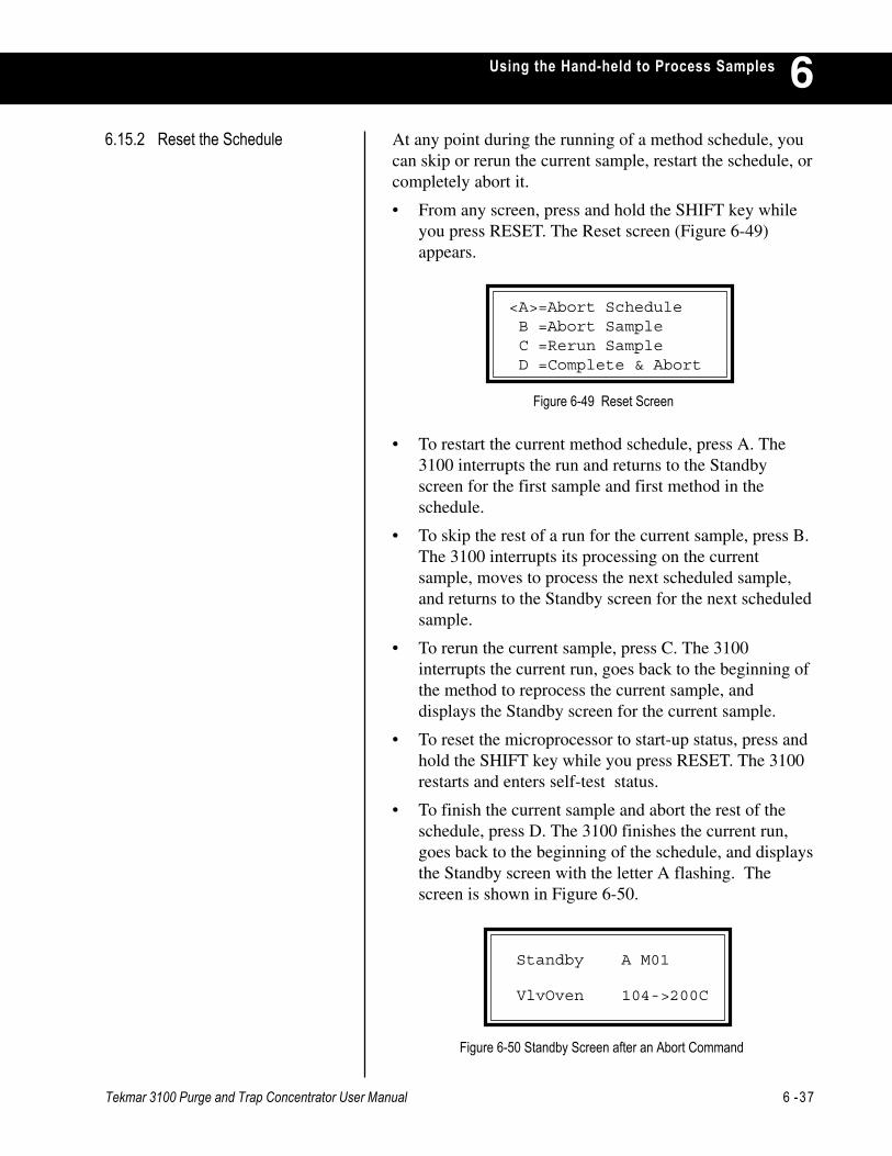
Tekmar 3100 Purge and Trap Concentrator User Manual 6 -37
Using the Hand-held to Process Samples 6
• To restart the current method schedule, press A. The3100 interrupts the run and returns to the Standbyscreen for the first sample and first method in theschedule.
• To skip the rest of a run for the current sample, press B.The 3100 interrupts its processing on the currentsample, moves to process the next scheduled sample,and returns to the Standby screen for the next scheduledsample.
• To rerun the current sample, press C. The 3100interrupts the current run, goes back to the beginning ofthe method to reprocess the current sample, anddisplays the Standby screen for the current sample.
• To reset the microprocessor to start-up status, press andhold the SHIFT key while you press RESET. The 3100restarts and enters self-test status.
• To finish the current sample and abort the rest of theschedule, press D. The 3100 finishes the current run,goes back to the beginning of the schedule, and displaysthe Standby screen with the letter A flashing. Thescreen is shown in Figure 6-50.
At any point during the running of a method schedule, youcan skip or rerun the current sample, restart the schedule, orcompletely abort it.
• From any screen, press and hold the SHIFT key whileyou press RESET. The Reset screen (Figure 6-49)appears.
6.15.2 Reset the Schedule
Figure 6-49 Reset Screen
Figure 6-50 Standby Screen after an Abort Command
<A>=Abort Schedule B =Abort Sample C =Rerun Sample D =Complete & Abort
Standby A M01
VlvOven 104->200C

6 -38 Tekmar 3100 Purge and Trap Concentrator User Manual
Using the Hand-held to Process Samples6
Figure 6-51 Schedule Status Screen
6.15.3 Review Current Status
• To cancel an attempted abort:
1. Press SHIFT-RESET on the keypad to display theAbort Schedule screen.
2. Press D. The 3100 picks up the once-abortedschedule at the point where it was discontinued.
The Schedule Status screen is display-only; to change anyparameters of the method schedule, press the SCHED keyto display the Scheduling screen.
· Line 1 displays the current sample position and the totalnumber of samples to be run according to the currentmethod.
· Line 2 shows the location of the currently-activesample. (If the 3100 is running a method, the currently-active sample is being processed. If the 3100 is notrunning a method, the currently-active sample is the onethat will be processed next.) Sample locations are:
0 .............. the single sample location on the front panelof the 3100.
1 to 16 ..... the sample positions on an 2016/6016Autosampler.
17 to 32 ... the sample positions on an 2032/6032Autosampler.
· Line 3 lists the number of the method that is currentlybeing run, or the method that will be run whenprocessing starts. Method values range from 1 to 16.
· Line 4 indicates whether or not the current methodincludes parameters for autosamplers.The availableoptions are: 3100 - includes parameters for the 3100front panel single sample; 60XX, 20XX, or AQUATek50/70, and AQUATek XX - includes parameters for anautosampler sample.
Sample # 1 of 1
Sample location: 0
Current Method: 1
Sample Type: 3100
You can review the currently-active schedule. When youpress A from the Scheduling screen, the Schedule Statusscreen (Figure 6-51) appears.
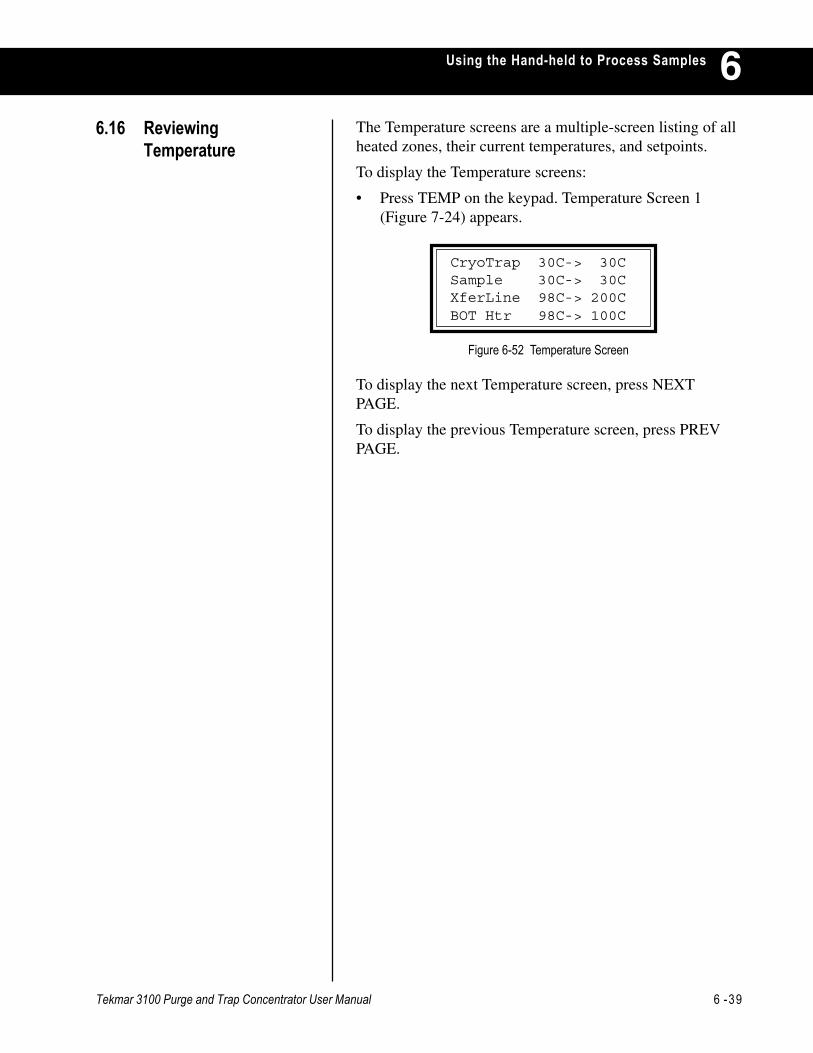
Tekmar 3100 Purge and Trap Concentrator User Manual 6 -39
Using the Hand-held to Process Samples 6The Temperature screens are a multiple-screen listing of allheated zones, their current temperatures, and setpoints.
To display the Temperature screens:
• Press TEMP on the keypad. Temperature Screen 1(Figure 7-24) appears.
Figure 6-52 Temperature Screen
To display the next Temperature screen, press NEXTPAGE.
To display the previous Temperature screen, press PREVPAGE.
6.16 ReviewingTemperature
CryoTrap 30C-> 30CSample 30C-> 30CXferLine 98C-> 200CBOT Htr 98C-> 100C


MAINTAINING THE 3100
Chapter 7

Tekmar 3100 Purge and Trap Concentrator User Manual 7 -1
Maintaining the 3100 7This section describes routine maintenance procedures forthe 3100 and tells you how to:
• Prepare and load standards.
• Prepare and load samples.
• Install or change the trap.
• Clean and condition the trap.
The accuracy of your analytical results depends on thecareful storage and use of accurately-prepared analyticalstandards. Purge and trap concentrator analyses are usuallyrun on samples with low analyte concentrations. The low-level standards required for such analyses must be of highquality; small errors that would be insignificant in a highlevel standard contribute to a large percentage of error in alow-level standard.
You can purchase commercially-prepared standards. A2LA-certified solutions are produced to A2LA/EPAspecifications. To ensure that a standard is certified and thatit meets your specifications, ask the manufacturer. Suppliersinclude AccuStandard, Inc. in New Haven, CT; ChemService Inc. in West Chester, PA; Restek in Bellefonte, PA;Supelco in Bellefonte, PA; or Ultra Scientific in NorthKingstown, RI. If you do not wish to buy standards, you canprepare your own.
Because the compounds usually being analyzed for arewater-insoluble and unstable in aqueous dilution, youcannot prepare an appropriate standard by dissolving thecompounds directly in water. The steps commonly used toprepare methanol solutions containing known amounts ofthe desired compounds are listed here:
• Prepare blank (reagent, or organic-free) water.
• Prepare a standard methanol solution at the specifiedconcentration.
• Spike the methanol standard into a flask of blank water.
7.2 Using Standards
7.1 Overview
7 -2 Tekmar 3100 Purge and Trap Concentrator User Manual
Maintaining the 31007
7.2.2 Prepare the MethanolStandard
7.2.1 Prepare Blank Water Blank water is water that analyzes as organic-free when runby purge and trap analysis. You can prepare blank water inseveral ways,
• Pass water through a freshly-charged Millipore Super Qwater purifier.
• Pass distilled water through a bed of activated carbon atleast 12" deep. Put the supply vessel at a higherelevation than the collection vessel, with the supply lineentering the column at the bottom. This configurationallows the water to flow from the bottom to top of thecolumn.
• Boil water; then purge it at 80-90°C with helium ornitrogen for at least one hour.
Note: You may use either of these preparation methods, althoughthe last two are the most common. No matter how youprepare blank water, you must check its purity by analysisbefore use, and you must use it immediately.
To prepare a methanol standard according to USEPA-approved procedures, follow these steps:
1. Fill a 10 ml volumetric flask with about 9.8 ml ofmethanol. Allow the flask to stand unstoppered until allalcohol-wetted surfaces have dried.
2. Weigh the flask and its contents accurately to thenearest 100 7g; this microgram value is W
1. Using a
100 ml syringe, immediately add two drops of neatstandard (minimum 75% purity) to the flask. Make surethe drops fall directly into the methanol withouttouching the neck of the flask.
4. Reweigh the flask with its contents; this microgramvalue is W
2.
5. Dilute the solution to volume (VC
in milliliters) withmethanol; then stopper the flask and invert it severaltimes to mix the solutions.
6. Calculate the concentration in micrograms per milliliter(W
2 - W
1)/V
C.
7. Transfer the solution to a 10 ml screw cap bottle with aTeflon cap liner, and store it at 6°C.
Tekmar 3100 Purge and Trap Concentrator User Manual 7 -3
Maintaining the 3100 7Methanol solutions containing 2-chloroethyl vinyl ether arestable for one week. Other solutions prepared in this wayare stable for up to four weeks. You can vary the methanoldilution to provide a range of standards.
7.2.3 Prepare the AqueousStandard
7.3 Preparing Samples
Prepare aqueous standards immediately before analysis.When you are ready to run an aqueous standard:
• Spike a measured quantity of the methanol standard intoa 100 ml volumetric flask filled with blank water; or
• Spike a measured quantity of the methanol standardthrough a microliter syringe into the luer fitting of thesample syringe.
Note: Do not inject more than 20 ml of methanol into 100 ml ofwater.
Sample size depends on many factors: the physical stateand homogeneity of the sample; the concentration andvapor pressure of target compounds; the type of detectorused, desired detection limits, and the type of GC column.Size has a major effect on the accuracy of the analysisbecause:
• Capillary columns require small samples (or splitinjection) to avoid column overloading.
• Sensitive detectors (like electron capture) require smallsamples to avoid saturation.
• Less volatile compounds or compounds present in lowconcentration require larger samples to be detectedaccurately, although they can overload columns andsaturate detectors.
For samples of unknown concentrations, Tekmarrecommends that you start small (at 0.25 mg for solids and0.5 ml for liquids) and increase as needed. It is usuallyeasier to optimize results by increasing sample size ratherthan decreasing it.
7.3.1 Select a Sample Size
Before you make an analytical run, you must select anappropriate sample size and load the selected sample.

7 -4 Tekmar 3100 Purge and Trap Concentrator User Manual
Maintaining the 31007You can load samples in either of two ways:
• For solid samples, remove the sample glassware, insertthe sample, weigh it in the glassware, and reinstall theglassware.
7.3.2 Load a Sample
• For aqueous samples, use a luer-lock syringe to load thesample through the sample valve without unloading theglassware. Follow these steps:
1. Remove the plunger from the syringe barrel.
2. Carefully pour the sample into the barrel until thesample overflows.
3. Insert the plunger and vent any air while adjusting theplungeR to the desired volume.
4. Turn the arrow on the valve stem so that it pointstoward the syringe. (At other times, when a sample isnot being loaded, the arrow on the valve stem shouldpoint to the left.)
5. Insert the syringe and load the sample through thesample valve.
The 3100 is delivered with a blank trap installed. Thisprevents damage to a packed trap if the instrument waspowered up with no purge gas flow present. You mustreplace the blank trap with a packed trap before you run asample.
Traps can be identified by a number stamped on the nut atthe top of the trap. Table 7-1 on the following pages givesdetailed information about traps and how to use them.
7.4.1 Information on Traps andAdsorbents
7.4 Working with Traps
CAUTION
If Auto Drain is on and you use U-shaped glassware to run asolid sample, you will damage the instrument.
CAUTION
Load only aqueous samples through the sample valve.
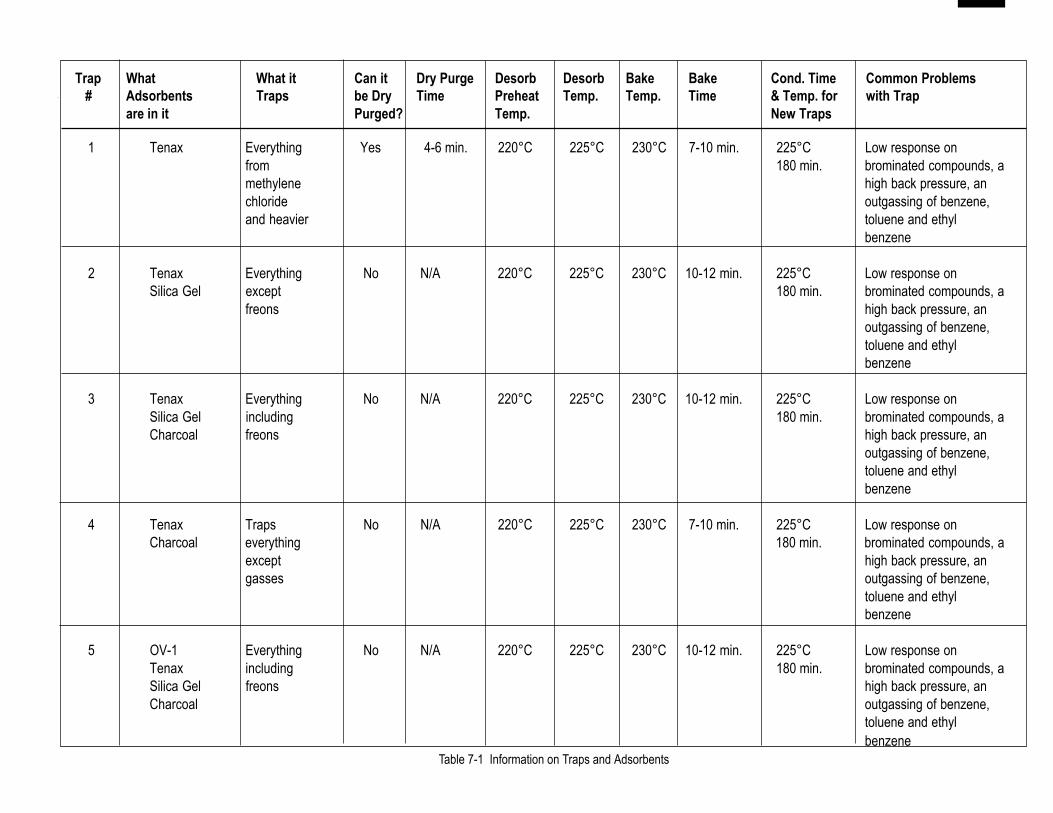
Tekmar 3100 Purge and Trap Concentrator User M
anual7 -7
Maintaining the 31007
1 Tenax Everything Yes 4-6 min. 220°C 225°C 230°C 7-10 min. 225°C Low response onfrom 180 min. brominated compounds, amethylene high back pressure, anchloride outgassing of benzene,and heavier toluene and ethyl
benzene
2 Tenax Everything No N/A 220°C 225°C 230°C 10-12 min. 225°C Low response onSilica Gel except 180 min. brominated compounds, a
freons high back pressure, anoutgassing of benzene,toluene and ethylbenzene
3 Tenax Everything No N/A 220°C 225°C 230°C 10-12 min. 225°C Low response onSilica Gel including 180 min. brominated compounds, aCharcoal freons high back pressure, an
outgassing of benzene,toluene and ethylbenzene
4 Tenax Traps No N/A 220°C 225°C 230°C 7-10 min. 225°C Low response onCharcoal everything 180 min. brominated compounds, a
except high back pressure, angasses outgassing of benzene,
toluene and ethylbenzene
5 OV-1 Everything No N/A 220°C 225°C 230°C 10-12 min. 225°C Low response onTenax including 180 min. brominated compounds, aSilica Gel freons high back pressure, anCharcoal outgassing of benzene,
toluene and ethylbenzene
Table 7-1 Information on Traps and Adsorbents
Trap What What it Can it Dry Purge Desorb Desorb Bake Bake Cond. Time Common Problems # Adsorbents Traps be Dry Time Preheat Temp. Temp. Time & Temp. for with Trap
are in it Purged? Temp. New Traps
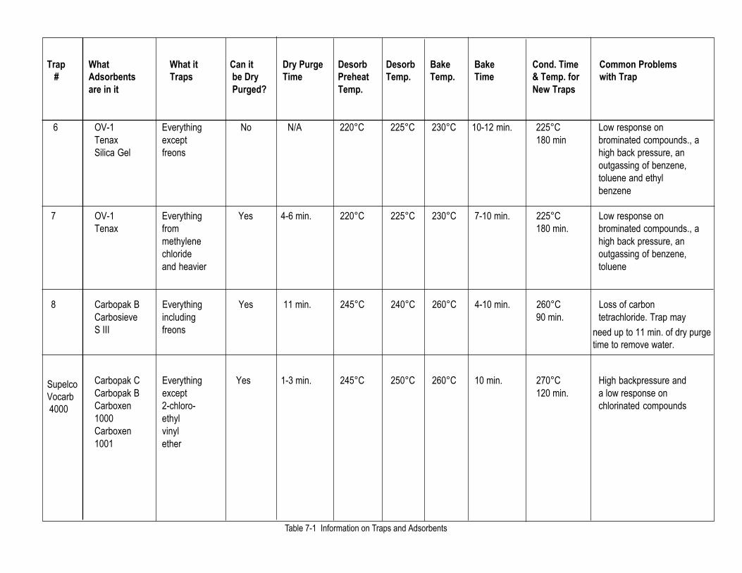
7 -P Tekm
ar 3100 Purge and Trap Concentrator User Manual
Maintaining the 3100
7
6 OV-1 Everything No N/A 220°C 225°C 230°C 10-12 min. 225°C Low response onTenax except 180 min brominated compounds., aSilica Gel freons high back pressure, an
outgassing of benzene,toluene and ethylbenzene
7 OV-1 Everything Yes 4-6 min. 220°C 225°C 230°C 7-10 min. 225°C Low response onTenax from 180 min. brominated compounds., a
methylene high back pressure, anchloride outgassing of benzene,and heavier toluene
8 Carbopak B Everything Yes 11 min. 245°C 240°C 260°C 4-10 min. 260°C Loss of carbonCarbosieve including 90 min. tetrachloride. Trap mayS III freons
Carbopak C Everything Yes 1-3 min. 245°C 250°C 260°C 10 min. 270°C High backpressure andCarbopak B except 120 min. a low response onCarboxen 2-chloro- chlorinated compounds1000 ethylCarboxen vinyl1001 ether
Table 7-1 Information on Traps and Adsorbents
Supelco Vocarb 4000
Trap What What it Can it Dry Purge Desorb Desorb Bake Bake Cond. Time Common Problems # Adsorbents Traps be Dry Time Preheat Temp. Temp. Time & Temp. for with Trap
are in it Purged? Temp. New Traps
need up to 11 min. of dry purgetime to remove water.

Tekmar 3100 Purge and Trap Concentrator User M
anual7 -9
Maintaining the 31007
Everythingincluding
freons
Everythingincluding
freons
Everythingdown tobenzene
(It does nottrap MeOH)
Carbopak BCarboxen
1000Carboxen
1001
Tenax GRGraphpac-D
Carbopak BCarbopak C
245OC
245OC
245OC
240OCto
250°C
250OC
250OC
Yes
Yes
Yes
260OC
260OC
260OC
4 min.
12 min.
4 min.
270OC 120 min.
____
270OC
Table 7-1 Information on Traps and Adsorbents
Supelco'sVocarb3100
AlltechTenax GR
Graphpac-D
Supelco'sBTEX
Decomposition ofbromoform can occur. Toprevent this fromhappening, reduceDesorb temp. to 240°C
Unknown
Unknown
120 min.
1-3 min.
1-4 min.
1-3 min.
Trap What What it Can it Dry Purge Desorb Desorb Bake Bake Cond. Time Common Problems # Adsorbents Traps be Dry Time Preheat Temp. Temp. Time & Temp. for with Trap
are in it Purged? Temp. New Traps
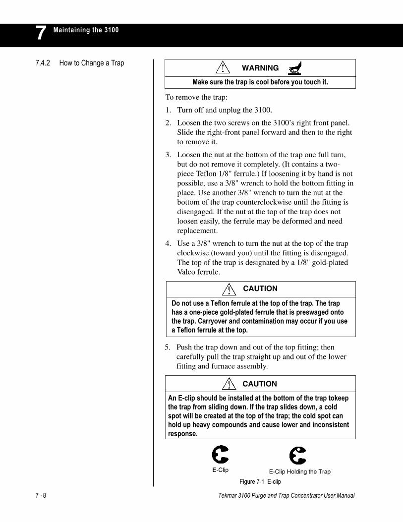
7 -8 Tekmar 3100 Purge and Trap Concentrator User Manual
Maintaining the 310077.4.2 How to Change a Trap
To remove the trap:
1. Turn off and unplug the 3100.
2. Loosen the two screws on the 3100’s right front panel.Slide the right-front panel forward and then to the rightto remove it.
3. Loosen the nut at the bottom of the trap one full turn,but do not remove it completely. (It contains a two-piece Teflon 1/8" ferrule.) If loosening it by hand is notpossible, use a 3/8" wrench to hold the bottom fitting inplace. Use another 3/8" wrench to turn the nut at thebottom of the trap counterclockwise until the fitting isdisengaged. If the nut at the top of the trap does notloosen easily, the ferrule may be deformed and needreplacement.
4. Use a 3/8" wrench to turn the nut at the top of the trapclockwise (toward you) until the fitting is disengaged.The top of the trap is designated by a 1/8" gold-platedValco ferrule.
5. Push the trap down and out of the top fitting; thencarefully pull the trap straight up and out of the lowerfitting and furnace assembly.
E-Clip Holding the Trap
Figure 7-1 E-clip
E-Clip
An E-clip should be installed at the bottom of the trap tokeepthe trap from sliding down. If the trap slides down, a coldspot will be created at the top of the trap; the cold spot canhold up heavy compounds and cause lower and inconsistentresponse.
CAUTION
CAUTION
Do not use a Teflon ferrule at the top of the trap. The traphas a one-piece gold-plated ferrule that is preswaged ontothe trap. Carryover and contamination may occur if you usea Teflon ferrule at the top.
Make sure the trap is cool before you touch it.
WARNING
Tekmar 3100 Purge and Trap Concentrator User Manual 7 -9
Maintaining the 3100 7To install a trap:
1. Slide a packed trap into the trap furnace sleeve from thetop, making sure that the one-piece gold-plated ferruleis at the top of the trap. When installed correctly, theferrule may be free to spin axially on the tubing, butshould have no lateral movement along the tubing.
2. Finger-tighten the top of the trap counterclockwise.While tightening the top, push up on the bottom of thetrap so that it is seated all the way up in the top fitting.To prevent gas from leaking at the fitting, use an openend wrench to tighten the nut 1/4 turn (90°) past thepoint where the ferrule first starts to grab the tubing. Donot overtighten; too much force will damage the ferrule,causing leaks.
If turning the nut 1/4 turn fails to eliminate a leak at thetop of the trap, look for other possible causes. Makesure that the correct size nut and ferrule are installedproperly. (See Step 1.) Also, examine the parts forfractures or deformities. If there are no flaws in theparts or installation, gradually tighten the nut inincrements of 1/16 turn only. Do not risk damaging theferrule; if a leak problem persists, call Tekmar-Dohrmann Service.
3. If the bottom 1/8" Teflon ferrule needs to be replaced,remove the nut and ferrule. Slide the bottom nut on thenew trap. Then slide the two-piece Teflon ferrule ontothe trap (with the cone side down).
4. Finger-tighten the bottom trap. (While tightening, pushthe trap up from the bottom fitting to make sure the trapis completely nested in the bottom of the trap fitting.)
5. Use a 3/8" wrench to tighten the fitting 1/16 turn pastfinger-tight. Do not overtighten; excess force willdamage the ferrule.
Trap lifetimes range from two weeks to five years, with theaverage being approximately six months. Tenax has asignificantly shorter lifetime than silica gel or charcoal.Silica gel and charcoal normally do not affect traplongevity.
7 -10 Tekmar 3100 Purge and Trap Concentrator User Manual
Maintaining the 31007
You condition a trap by heating (baking) it in the 3100. Theconditioning time and temperature can vary, depending onthe type of trap you are using. To find out the correctconditioning time and temperature for a new trap, see Table7-1, check with the trap manufacturer or call Tekmar-Dohrmann Service at (800) 543-4461 or (513) 247-7000.
If organic solvents are present in the ambient atmosphere,Tekmar recommends that you condition the trap for 10minutes at 225°C at the start of each day. This time andtemperature are usually adequate for silica gel and charcoaltraps. However, if the trap is heavily loaded or if you arerunning samples containing compounds of low volatility,you may have to bake the trap longer than 10 minutes.Keep in mind that temperatures above 225°C do notnecessarily speed up conditioning and can damage Tenaxtraps.
To condition a trap:
1. Check the Method. The Bake temperature should be thecorrect temperature for conditioning the trap.
2. Press SHIFT-GO TO.
3. Press the A key (Go to Mode).
4. Press the C key (Bake).
5. Press SHIFT-HOLD to keep the 3100 in Bake mode forthe proper amount of conditioning time.
7.4.4 Conditioning a Trap
7.4.3 When to Replace a Trap Indicators of trap wear are:
• Increase in background. This usually takes the form ofbenzene and other aromatics in instrument blanks.
• Losses of brominated compounds while othercompounds are constant.
• Increase in back pressure.

Tekmar 3100 Purge and Trap Concentrator User Manual 7 -11
Maintaining the 3100 77.5 Cleaning Sample
LinesThe 3100 may become seriously contaminated from ahighly concentrated sample or a poor quality gas supply.To avoid contamination, keep the sample lines clean.
To remove sample-caused contamination:
1. Turn Bake Gas Bypass (BGB) OFF and install clean,dry glassware.
2. Press SHIFT-GO TO. Press the A key (Go To Mode).Press the C key (Bake). Press SHIFT-HOLD.
3. Keep the unit in Bake mode for at least 1 hour. In somecases, longer durations might be required.
If baking does not remove contamination, you may want tobackflush the lines with the Tekmar-Dohrmann SolventFlush Kit (P/N 14-5118-100). Call Tekmar-Dohrmann at(800) 874-2004 or (513) 247-7000 to order.
To remove contamination resulting from the use of poorquality gas:
1. First replace the tank and all hydrocarbon traps on thegas supply line. This process may be sufficient toobtain good blanks. If not, press SHIFT-GO TO. Pressthe A key (Go To Mode). Press the C key (Bake). PressSHIFT-HOLD.
2. Keep the 3100 in Bake mode for at least 1 hour. Insome cases, longer times might be required. If thecontamination problem persists, call Tekmar-Dohrmann’s Service Department for assistance.
7 -12 Tekmar 3100 Purge and Trap Concentrator User Manual
Maintaining the 31007
You must clean the sample needle on a routine basis.Frequency of cleaning depends on the kind of samples youare running. If you are running aqueous samples, you donot need to clean the sample needle very often. If you arerunning oils and other messy samples, you must clean theneedle after every run.
To clean the sample needle:
1. Wash the needle with Alconox detergent (or equivalent)and water.
2. Rinse well with blank water.
3. If the needle does not get clean, bake it for about twohours at 65°C (149°F).
7.7 Cleaning the SampleNeedle
7.6 Cleaning Glassware Clean glassware is essential to interference-free runs. Thisapplies to flasks and cylinders as well as samplers (that is,any vessel used to handle samples, standards, blank water,etc.)
To clean glassware, Tekmar-Dohrmann recommends thatyou use the following:
• Dedicated glassware
• Ultrasonic bath
• Muffle furnace
Dedicated glassware refers to glassware that is used forconcentrator work only. Glassware that is used for otherprocedures such as extractions, often is not clean enough touse in trace applications.
An ultrasonic bath is a time-saver. Instead of heavyscrubbing, a brief scrubbing followed by ultrasonics is moreeffective and less work.
Ultrasonic baths can clean the frits and walls of fritsamplers that brushes cannot reach. It is acceptable to useany glassware detergents that are recommended for use inan ultrasonic bath. (We recommend that you use theTekmar-Dohrmann Ultrasonic Bath.)
A muffle furnace is excellent for cleaning many samplers thatnothing else can touch. Set the temperature to approximately350-400°C (do not go too high; the glassware may melt) andallow the residues to be oxidized. After the glassware hascooled, you can easily remove the remaining char with a brushand cleaning agent. (We recommend the TekmarTM MuffleFurnace.)

USING TURBOCOOL WITH THE 3100
Chapter 8

Tekmar 3100 Purge and Trap Concentrator User Manual 8 -1
Using TURBOCool with the 3100 8This section describes how to use TURBOCool with the3100. To install TURBOCool on the 3100, see theinstallation instructions shipped with the TURBOCoolassembly kit. Also refer to the parts diagram at the end ofthis chapter.
TURBOCool, an optional accessory to the 3100, uses liquidCO
2 (carbon dioxide) to permit purging onto a subambient
trap. TURBOCool can be installed into the 3100 in one ofthe following ways:
• By factory personnel before the 3100 is shipped
• By a Tekmar-Dohrmann Field Service Representative
• By ordering an installation kit and doing it yourself
The 3100 with TURBOCool is built the same as the 3100without TURBO-Cool except for:
• A special trap furnace that is inserted into a chamberassembly
• The addition of a 12 VDC coolant valve
• The addition of a bulkhead at the rear of the 3100
The special trap furnace is inserted into an expansionchamber assembly.
Then it is connected to the top and bottom trap fittings.
The 12 VDC coolant valve is mounted underneath the MCS(Moisture Control System). It plugs into the connectorlabeled "A" on the power supply/output card.
The bulkhead, which provides connections for tubing, ismounted to the inlet vent on the rear of the 3100. Coolantflows from the supply cylinder to the 3100 through thetubing.
More detailed installation instructions are shipped with theTURBOCool assembly kit.
8.1 Overview
8.2 Description
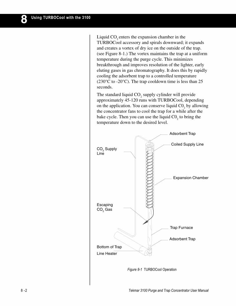
8 -2 Tekmar 3100 Purge and Trap Concentrator User Manual
Using TURBOCool with the 31008
Figure 8-1 TURBOCool Operation
Bottom of Trap
Line Heater
Adsorbent Trap
Trap Furnace
EscapingCO
2 Gas
Expansion Chamber
Adsorbent Trap
Coiled Supply LineCO
2 Supply
Line
Liquid CO2 enters the expansion chamber in the
TURBOCool accessory and spirals downward; it expandsand creates a vortex of dry ice on the outside of the trap.(see Figure 8-1.) The vortex maintains the trap at a uniformtemperature during the purge cycle. This minimizesbreakthrough and improves resolution of the lighter, earlyeluting gases in gas chromatography. It does this by rapidlycooling the adsorbent trap to a controlled temperature(230°C to -20°C). The trap cooldown time is less than 25seconds.
The standard liquid CO2 supply cylinder will provide
approximately 45-120 runs with TURBOCool, dependingon the application. You can conserve liquid C0
2 by allowing
the concentrator fans to cool the trap for a while after thebake cycle. Then you can use the liquid C0
2 to bring the
temperature down to the desired level.

Tekmar 3100 Purge and Trap Concentrator User Manual 8 -3
Using TURBOCool with the 3100 8Broad, jagged, and poorly resolved peaks are a commonresult of the permanent gases that are extremely volitile(dichlorodifluoromethane, chloromethane, vinyl chloride,bromomethane, chloroethane and trichlorofluoromethane)and rapidly migrate through the adsorbent trap on theconcentrator. This results in minimal interaction betweenthe analytes and the trap sorbent, leaving a broad band ofanalytes to enter the chromatographic column. Broad,jagged, poorly resolved peaks are a common result.
TURBOCool improves chromatographic performance intwo ways:
• First, it cools the trap to a preset temperature; thisincreases reproducibility because the trap stays at thesame temperature for each analysis.
• Second, at subambient temperatures, the purgedanalytes stay focused in a narrow band on the trap.When the trap is quickly heated and backflushed in thedesorption mode, the compounds stay in a tight band asthey deposit on the head of the column. This results inbetter peak shape, resolution, sensitivity, andreproducibility of the permanent gases. See the samplechromatograms.
You can use TURBOCool in conjunction with a low volumeinsert or your GC injection port to permit GC-directinjections. TURBOCool also improves purge and trap gaschromatography when using different column geometries.
8.3 Applications
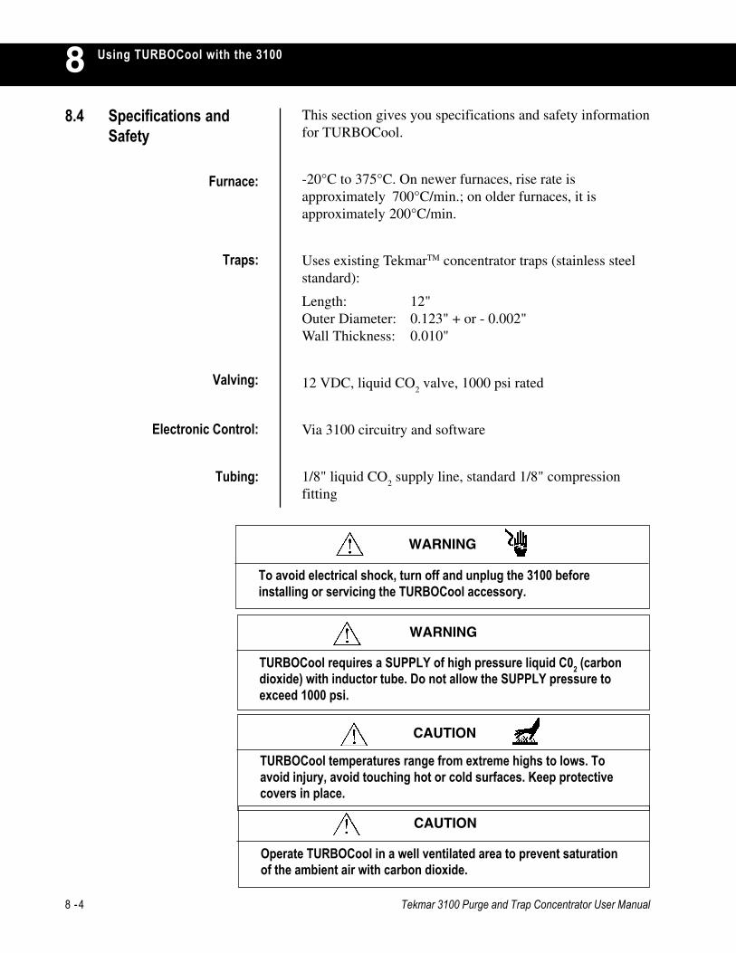
8 -4 Tekmar 3100 Purge and Trap Concentrator User Manual
Using TURBOCool with the 310088.4 Specifications and
SafetyThis section gives you specifications and safety informationfor TURBOCool.
-20°C to 375°C. On newer furnaces, rise rate isapproximately 700°C/min.; on older furnaces, it isapproximately 200°C/min.
Uses existing TekmarTM concentrator traps (stainless steelstandard):
Length: 12"Outer Diameter: 0.123" + or - 0.002"Wall Thickness: 0.010"
12 VDC, liquid CO2 valve, 1000 psi rated
Via 3100 circuitry and software
1/8" liquid CO2 supply line, standard 1/8" compression
fitting
Furnace:
Traps:
Valving:
Electronic Control:
Tubing:
TURBOCool requires a SUPPLY of high pressure liquid C02 (carbondioxide) with inductor tube. Do not allow the SUPPLY pressure toexceed 1000 psi.
WARNING
To avoid electrical shock, turn off and unplug the 3100 beforeinstalling or servicing the TURBOCool accessory.
WARNING
CAUTION
TURBOCool temperatures range from extreme highs to lows. Toavoid injury, avoid touching hot or cold surfaces. Keep protectivecovers in place.
Operate TURBOCool in a well ventilated area to prevent saturationof the ambient air with carbon dioxide.
CAUTION

Tekmar 3100 Purge and Trap Concentrator User Manual 8 -5
Using TURBOCool with the 3100 8Some time after the 3100 completes the Bake step, it entersthe Turbo Cooldown step. During this step, theTURBOCool trap cools to its low temperature setpoint fortrapping analytes. The GC cycle time (GC run time pluscooldown time) determines when the Turbo Cooldown stepbegins. For example, suppose the time to complete one GCcycle is 40 minutes and the time to complete one 3100 cycleis 35 minutes. To coordinate the GC cycle time with its owncycle time, the 3100 waits five minutes after the end ofBake before advancing to Turbo Cooldown. The 3100calculates the length of the delay (up to 1000 minutes),based on the GC cycle time. This waiting period is calledthe GC Synchronize step. This step not only providessmooth coordinated operation, it also conserves CO
2 by not
allowing Turbo Cooldown to start too soon.
If the GC cycle time is less than the 3100 cycle time, the3100 will step directly into Turbo Cooldown after bake.
If you have installed a TURBOCool accessory and arerunning multiple samples, the GC Synchronize stepreplaces Purge Ready between runs.
Two method parameters are associated with TURBOCool:
• TURBOCool Temperature
• GC Cycle Time
The TURBOCool temperature, which is analyte-specific, isthe temperature of the TURBOCool trap. Choose acooldown temperature that is recommended by the USEPA(United States Environmental Protection Agency).
Program the 3100 to cool the TURBOCool trap to a certaintemperature by:
• using a default method that includes the desiredtemperature.
or
• editing your own, customized method.
8.5 TURBOCool andOperating Cycle Times
8.6 TURBOCool MethodParameters
8 -6 Tekmar 3100 Purge and Trap Concentrator User Manual
Using TURBOCool with the 31008The time at which the 3100 advances to Turbo Cooldownmode is based upon operating cycle times. (See the previoussection).
To determine GC cycle time:
1. monitor the time it takes for the GC to cool from itsbake temperature to starting temperature.
2. add this time to the GC run time.
Program the 3100 to recognize the GC cycle time by:• using a default method that includes the desired GC
cycle time.
or
• editing your own, customized method.
The 3100:
1. determines the time needed to complete its modes ofoperation.
2. subtracts this time from the GC cycle time.
3. uses this quantity to determine the time at which theCO
2 valve activates and Turbo Cooldown begins.
This section lists replacement parts for the TURBOCoolaccessory.
To order parts, ask technical questions, or obtain service,call one of the following numbers:
• (800) 543-4461 - toll-free in the US and Canada
• (513) 247-7000 - outside the US and Canada
Before you call for service or parts:
1. Note the model name, model number, and serial numberof the 3100.
2. If requesting assistance or service, note the type ofproblem you are having: write down the conditionsunder which the problem occurred and the display,activity, or result that indicated the existence of aproblem.
3. When ordering parts, write down the part number, partname, and quantity needed.
8.7 Ordering Parts orObtaining Service

Tekmar 3100 Purge and Trap Concentrator User Manual 8 -7
Using TURBOCool with the 3100 814-5763-100 TURBOCool assembly kit
14-5717-120 Trap heater, TURBOCool, 3100
14-5678-016 Elbow, 1/4" - 1/4", brass
14-5634-400 Power lead, cryo valve, 25" long
14-5582-179 Assembly, chamber, expansion
14-5467-022 Clamp, 3/4" dia.
14-4812-016 Union, reducing, 1/2" - 1/4"
14-4811-016 Flare nut, short, 1/2 OD
14-4810-002 Tubing, 1/2" OD, 2" long, copper
14-3268-046 Spacer, #6 x 1/4" long, 1/4" OD, alum
14-3105-186 Cable assembly, cryo to LN2 valve
14-2531-100 Valve assembly, LN2, light grey
14-1652-004 Insulation, pipe, 3/8" ID x 1/2" W
14-1313-002 Tubing, copper, 1/4" dia., raw
14-1070-004 Insulation, varglass, type H, 3/4 natural
14-0485-109 Washer, lock int. tooth, #6
12-0388-030 Heat shrink, 3/4, black
12-0325-210 Nut, hex, 6-32, SS
12-0323-C01 Screw, #6-32 x 1/2, pan head
12-0317-407 Grommet, 0.625 ID, 0.937 mount hole


TROUBLESHOOTING THE 3100
Chapter 9

Tekmar 3100 Purge and Trap Concentrator User Manual 9 -1
9Troubleshooting the 3100
This section gives you basic troubleshooting information.
This chapter is divided into four parts:
• Calling Tekmar-Dohrmann Service
• Safety
• Troubleshooting Electomechanical Problems
• Understanding Error Screens
If you need assistance solving a problem, follow these steps:
1. Note the model name, model number, and serial numberof the instrument.
2. Note the type of problem you are having: write downthe conditions under which the problem occurred andthe display, activity, or result that indicated theexistence of a problem.
3. Call Tekmar-Dohrmann Service at one of the followingnumbers:
9.1 Overview
Before you troubleshoot, please read the safety informationin this section.
9.3 Safety
9.2 Calling TekmarDohrmann Service
Unless the pneumatic lines are badly contaminated, do not flushthem with a strong solvent, such as methanol; use waterinstead. The valve rotor can adsorb strong solvents and becomecontaminated. If you must use a strong solvent, rinse the linesthoroughly with water after cleaning them.
CAUTION
• (800) 874-2004 - toll-free in the US and Canada
• (513) 247-7000 - outside the US and Canada
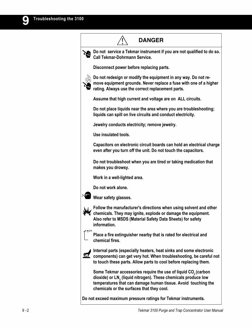
9 -2 Tekmar 3100 Purge and Trap Concentrator User Manual
Troubleshooting the 31009
Do not service a Tekmar instrument if you are not qualified to do so.Call Tekmar-Dohrmann Service.
Disconnect power before replacing parts.
Do not redesign or modify the equipment in any way. Do not re-move equipment grounds. Never replace a fuse with one of a higherrating. Always use the correct replacement parts.
Assume that high current and voltage are on ALL circuits.
Do not place liquids near the area where you are troubleshooting;liquids can spill on live circuits and conduct electricity.
Jewelry conducts electricity; remove jewelry.
Use insulated tools.
Capacitors on electronic circuit boards can hold an electrical chargeeven after you turn off the unit. Do not touch the capacitors.
Do not troubleshoot when you are tired or taking medication thatmakes you drowsy.
Work in a well-lighted area.
Do not work alone.
Wear safety glasses.
Follow the manufacturer's directions when using solvent and otherchemicals. They may ignite, explode or damage the equipment.Also refer to MSDS (Material Safety Data Sheets) for safetyinformation.
Place a fire extinguisher nearby that is rated for electrical andchemical fires.
Internal parts (especially heaters, heat sinks and some electroniccomponents) can get very hot. When troubleshooting, be careful notto touch these parts. Allow parts to cool before replacing them.
Some Tekmar accessories require the use of liquid CO2 (carbondioxide) or LN2 (liquid nitrogen). These chemicals produce lowtemperatures that can damage human tissue. Avoid touching thechemicals or the surfaces that they cool.
Do not exceed maximum pressure ratings for Tekmar instruments.
DANGER
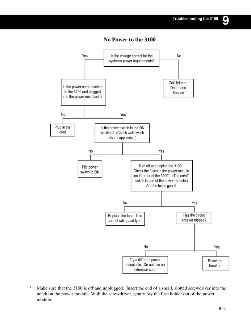
9 -3
9TTroubleshooting the 3100
No Power to the 3100
* Make sure that the 3100 is off and unplugged. Insert the end of a small, slotted screwdriver into thenotch on the power module. With the screwdriver, gently pry the fuse holder out of the powermodule.
Yes No
Is the power cord attachedto the 3100 and plugged
into the power receptacle?
Is the voltage correct for thesystem's power requirements?
Call Tekmar-Dohrmann
Service
Flip powerswitch to ON
Turn off and unplug the 3100.Check the fuses in the power moduleon the rear of the 3100*. (The on/offswitch is part of the power module.)
Are the fuses good?
Replace the fuse. Usecorrect rating and type.
Has the circuitbreaker tripped?
Try a different powerreceptacle. Do not use an
extension cord!
Reset thebreaker.
YesNo
Plug in thecord
Is the power switch in the ONposition? (Check wall switch
also, if applicable.)
No
No
No
Yes
Yes
Yes

9 -4 Tekmar 3100 Purge and Trap Concentrator User Manual
Troubleshooting the 31009
* To check for leaks, see the leak problems flow chart in this section.
No Purge Flow Out of the Vent
Yes, Bubbles No, Bubbles
YesNo Is there sparging through thesparge tube?
Is the purge gassupply on?
Do bubbles stop within0 to 7 min. withoutcapping the vent?
Is there flow out ofthe sample valve?
Set to 20 psi.
Check all fittings before thesparger for leaks or blockage.Use a flow meter to check for
flow. if there is no flow, check foreither a blockage or a leak.*
Call Tekmar-DohrmannService.
Is the flowcontroller open? Turn on gas
Is there 20psi onthe gauge?
Set flow controllerto 40 ml/min.
Yes
Yes
Yes
Yes
No
No
No
No
Check for leaks.(See leak problems
flow chart in thissection.)
Disconnect the top of trap andother points to see if bubbles start.
Blockage is likelybetween the
sample mount andthe top of trap
fitting.
Blockage is likelybetween the vent
and top of trapfitting.

Tekmar 3100 Purge and Trap Concentrator User Manual 9 -5
9TTroubleshooting the 3100
Leak ProblemsCAUTION:
Do not tighten nutsmore than finger-
tight, plus 1/4 turn.Too much forcedamages the
ferrules.
Put 5ml of water in sparger. Cap vent. Step to purge and hold.Turn off heaters and disconnect fans
Bubbling Stops Bubbling does not stop
Before During
Did it stop bubblingwithin 3 to 14 minutes?
Check all ferrules in the instrument.• at bottom of trap• at top of needle• at top of glassware
Does it purgeinitially?
Finished
Cap off at thebottom of the
trap fitting.
FinishedCheck all fittingsbefore the glassware.
Refer to the diagram inthe manual.
Check forcrackedferrules.
Go to the flow chart titled,No Purge Flow Out of the
Vent in this section.
If the leak is before the trap,check all fittings between the
trap and the glassware.Retest
Still thesame?
Go to step IIIGo to step II
If the leak is after thetrap, check the trap
fitting and vent.
Check Teflonferrule forabnormal
shape.
Cap the N/Cposition onthe HRP
valve.
FinishedFinished
Check allferrules for
cracks.
Replaceferrule.
Go tostep I.
Finished
Call Tekmar-DohrmannService.
Replaceferrules.
Call Tekmar-DohrmannService.
Finished
Replace allbad
ferrules.
Call Tekmar-DohrmannService.
Call Tekmar-DohrmannService.
Finished
Call Tekmar-DohrmannService.
Finished
Check ferrules onfittings after trap.
Finished
I
II
III
Yes No Still Stopped
Still Stopped
Still StoppedStill Stopped
Normal Abnormal
Good Cracked
StoppedStill
Still Stopped
Bad
Still Stopped
Still Stopped
Good

9 -6 Tekmar 3100 Purge and Trap Concentrator User Manual
Troubleshooting the 31009Reduced Sensitivity
Bubbles
Do severaldirect injectionson GC column
Bad chromatograms
Goodchromatograms
Bubbles No Bubbles Early Late
Troubleshoot GC.Use GC manual.
Fill spargevessel withwater. Cap
off vent. Check chromatogramsfor problems with early
or late eluters
Breakthrough -reduce purge
time.
Change trap.
Change trap.
Finished
Finished
Finished
CallTekmar-
DohrmannServiceAre the
compoundsbrominated?
Checkglasswarefitting
Rununit. Ifstill bad,
go toStep II
Checkconnection
betweenthe 3100and GC.
Active sites - CallTekmar-Dohrmann
Service
Call Tekmar-Dohrmann
Service
No BubblesBubbles
Run unit.If still bad,go to Step
II.
Check otherfittings in
unit.
No Bubbles
Good Bad
Bad Good
Yes No
Bad Good
I II
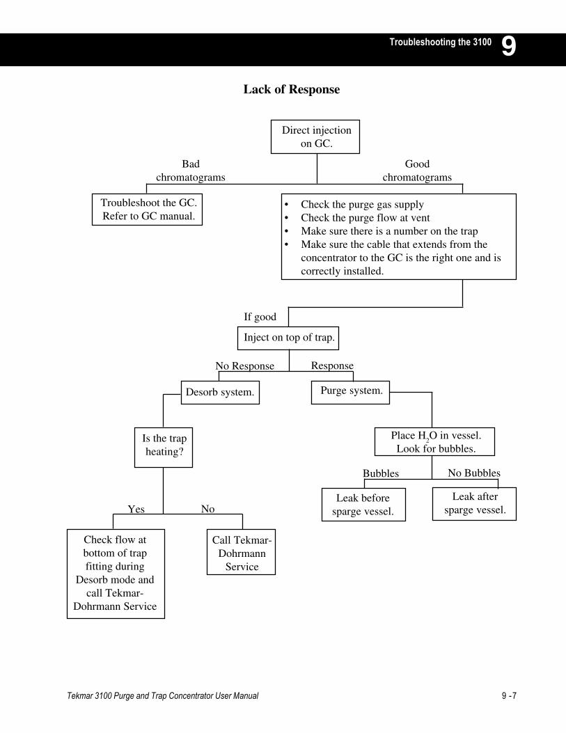
Tekmar 3100 Purge and Trap Concentrator User Manual 9 -7
9TTroubleshooting the 3100
Lack of Response
Direct injectionon GC.
Troubleshoot the GC.Refer to GC manual.
• Check the purge gas supply• Check the purge flow at vent• Make sure there is a number on the trap• Make sure the cable that extends from the
concentrator to the GC is the right one and iscorrectly installed.
Inject on top of trap.
Purge system.Desorb system.
Place H2O in vessel.
Look for bubbles.Is the trapheating?
Leak beforesparge vessel.
Leak aftersparge vessel.
Check flow atbottom of trapfitting during
Desorb mode andcall Tekmar-
Dohrmann Service
Call Tekmar-Dohrmann
Service
Badchromatograms
Goodchromatograms
If good
ResponseNo Response
Yes No
Bubbles No Bubbles

9 -8 Tekmar 3100 Purge and Trap Concentrator User Manual
Troubleshooting the 31009Carryover Contamination
Did you run a high level sample?
If still bad, go to Step II
Reconnect trap and bake
Set it to 100°C
Purge 10-20 minutes
Remove H2O
Purge 30 minutes
With H2O bath, heat sparger to
100°C. Go to Step I
Do you have a sample heater?
Call Tekmar-Dohrmann Service
Put 3100 in Bake mode for 30minutes with trap disconnected and
temperatures elevated
Flush 75 ml of H2O -collect in sparger
Flush with 25 ml of asolvent (methanol)
Connect a syringe with an adapter tothe trap (14-5118-100)
Steam clean... Finished
Leave valve and line temps up
Disconnect the top of the trapor install a #6 trap. Caution!
Trap may be hot!
You have vapor phase adsorption You have liquid phase deposition
See caution on page 1 of this section.Clean with solvent (methanol)...
Turn heaters down to < 50°C.
Backflush
Remove trap and purge line tosparger. Caution! Trap may be hot!
Yes No
Put 3100 in Bake mode for about an hour
Bad Good
Finished
Put 5-10 mls of blankH
2O in sparger
II
I
YesNo
Bad Good

SERVICE AND PARTS
Chapter 10


Tekmar 3100 Purge and Trap Concentrator User Manual 10 -1
Service and Parts 10To order parts, ask technical questions, or obtain service,call one of the following numbers:
• (800) 543-4461 - toll-free in the US and Canada
• (513) 247-7000 - outside the US and Canada
10.1 Calling Sales orService
Before you call for service or parts:
• Note the model name, model number, and serial numberof the instrument.
• If requesting assistance or service, note the type ofproblem you are having: write down the conditionsunder which the problem occurred and the display,activity, or result that indicated the existence of aproblem.
• When ordering parts, write down the part number, partname, and quantity needed.
This section lists part numbers and names for 3100replacement parts. which are listed by type.
10.2 3100 Parts List

10 -2 Tekmar 3100 Purge and Trap Concentrator User Manual
Service and Parts1014-2337-024 5ml Frit Sparger (glassware only)
14-2334-024 25ml Frit Sparger (glassware only)
14-2336-024 5ml Fritless Sparger (glassware only)
14-2333-024 25ml Fritless Sparger (glassware only)
14-2052-024 5ml Needle Sparger (glassware only)
14-2053-024 25ml Needle Sparger (glassware only)
14-3096-100 5ml Frit Sparger Kit
14-3095-100 25ml Frit Sparger Kit
14-3094-100 5ml Fritless Sparger Kit
14-3093-100 25ml Fritless Sparger Kit
14-3599-100 5ml Needle Sparger Kit
14-3600-100 25ml Needle Sparger Kit
14-4817-024 5ml Fritless Sparger, right intro stem for usewith 2050 or AQUATek 50
14-4818-024 25ml Fritless Sparger, right intro stem foruse with 2050 or AQUATek 50
14-3544-024 5ml Frit Sparger, w/left introduction stemfor 2050 or AQUATek 50
14-3546-024 25ml Frit Sparger, w/left introduction stemfor 2050 or AQUATek 50
14-3544-124 5ml Frit Sparger, w/right introduction stemfor 2050 or AQUATek 50
14-3546-124 25ml Frit Sparger, w/right introduction stemfor 2050 or AQUATek 50
10.2.1 Glassware
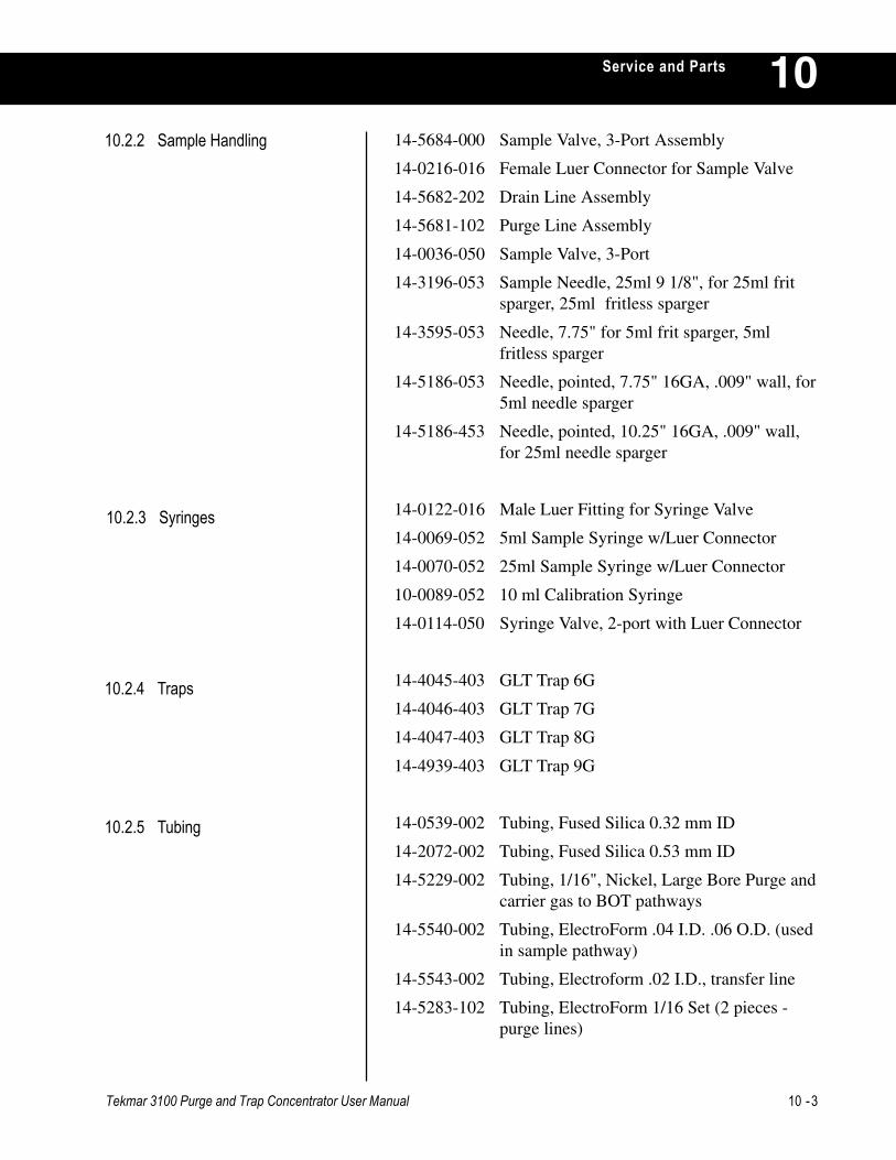
Tekmar 3100 Purge and Trap Concentrator User Manual 10 -3
Service and Parts 1014-5684-000 Sample Valve, 3-Port Assembly
14-0216-016 Female Luer Connector for Sample Valve
14-5682-202 Drain Line Assembly
14-5681-102 Purge Line Assembly
14-0036-050 Sample Valve, 3-Port
14-3196-053 Sample Needle, 25ml 9 1/8", for 25ml fritsparger, 25ml fritless sparger
14-3595-053 Needle, 7.75" for 5ml frit sparger, 5mlfritless sparger
14-5186-053 Needle, pointed, 7.75" 16GA, .009" wall, for5ml needle sparger
14-5186-453 Needle, pointed, 10.25" 16GA, .009" wall,for 25ml needle sparger
14-0122-016 Male Luer Fitting for Syringe Valve
14-0069-052 5ml Sample Syringe w/Luer Connector
14-0070-052 25ml Sample Syringe w/Luer Connector
10-0089-052 10 ml Calibration Syringe
14-0114-050 Syringe Valve, 2-port with Luer Connector
14-4045-403 GLT Trap 6G
14-4046-403 GLT Trap 7G
14-4047-403 GLT Trap 8G
14-4939-403 GLT Trap 9G
14-0539-002 Tubing, Fused Silica 0.32 mm ID
14-2072-002 Tubing, Fused Silica 0.53 mm ID
14-5229-002 Tubing, 1/16", Nickel, Large Bore Purge andcarrier gas to BOT pathways
14-5540-002 Tubing, ElectroForm .04 I.D. .06 O.D. (usedin sample pathway)
14-5543-002 Tubing, Electroform .02 I.D., transfer line
14-5283-102 Tubing, ElectroForm 1/16 Set (2 pieces -purge lines)
10.2.4 Traps
10.2.3 Syringes
10.2.2 Sample Handling
10.2.5 Tubing
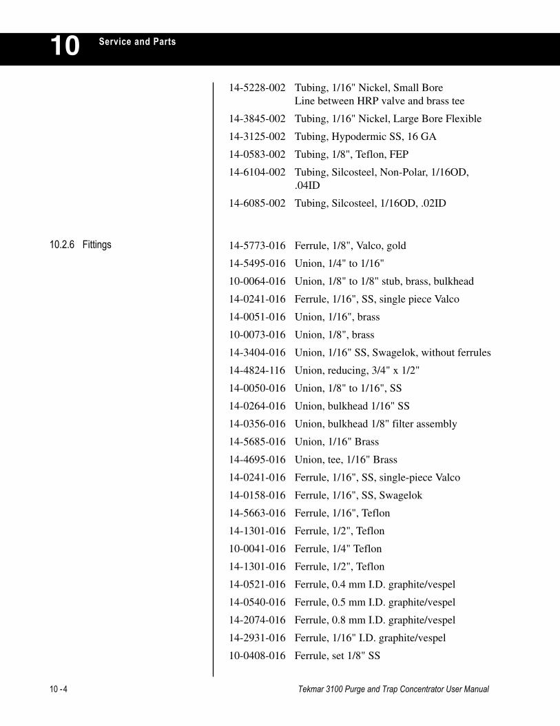
10 -4 Tekmar 3100 Purge and Trap Concentrator User Manual
Service and Parts10
14-5773-016 Ferrule, 1/8", Valco, gold
14-5495-016 Union, 1/4" to 1/16"
10-0064-016 Union, 1/8" to 1/8" stub, brass, bulkhead
14-0241-016 Ferrule, 1/16", SS, single piece Valco
14-0051-016 Union, 1/16", brass
10-0073-016 Union, 1/8", brass
14-3404-016 Union, 1/16" SS, Swagelok, without ferrules
14-4824-116 Union, reducing, 3/4" x 1/2"
14-0050-016 Union, 1/8" to 1/16", SS
14-0264-016 Union, bulkhead 1/16" SS
14-0356-016 Union, bulkhead 1/8" filter assembly
14-5685-016 Union, 1/16" Brass
14-4695-016 Union, tee, 1/16" Brass
14-0241-016 Ferrule, 1/16", SS, single-piece Valco
14-0158-016 Ferrule, 1/16", SS, Swagelok
14-5663-016 Ferrule, 1/16", Teflon
14-1301-016 Ferrule, 1/2", Teflon
10-0041-016 Ferrule, 1/4" Teflon
14-1301-016 Ferrule, 1/2", Teflon
14-0521-016 Ferrule, 0.4 mm I.D. graphite/vespel
14-0540-016 Ferrule, 0.5 mm I.D. graphite/vespel
14-2074-016 Ferrule, 0.8 mm I.D. graphite/vespel
14-2931-016 Ferrule, 1/16" I.D. graphite/vespel
10-0408-016 Ferrule, set 1/8" SS
10.2.6 Fittings
14-5228-002 Tubing, 1/16" Nickel, Small BoreLine between HRP valve and brass tee
14-3845-002 Tubing, 1/16" Nickel, Large Bore Flexible
14-3125-002 Tubing, Hypodermic SS, 16 GA
14-0583-002 Tubing, 1/8", Teflon, FEP
14-6104-002 Tubing, Silcosteel, Non-Polar, 1/16OD,.04ID
14-6085-002 Tubing, Silcosteel, 1/16OD, .02ID
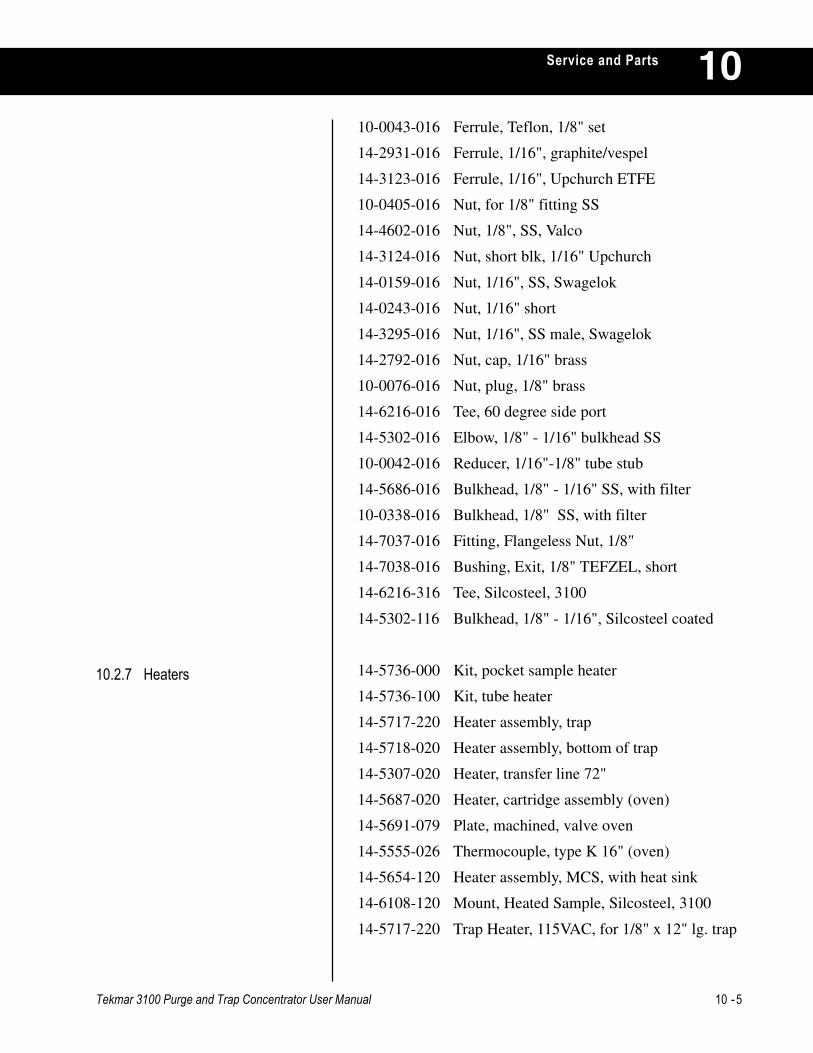
Tekmar 3100 Purge and Trap Concentrator User Manual 10 -5
Service and Parts 10
10.2.7 Heaters
10-0043-016 Ferrule, Teflon, 1/8" set
14-2931-016 Ferrule, 1/16", graphite/vespel
14-3123-016 Ferrule, 1/16", Upchurch ETFE
10-0405-016 Nut, for 1/8" fitting SS
14-4602-016 Nut, 1/8", SS, Valco
14-3124-016 Nut, short blk, 1/16" Upchurch
14-0159-016 Nut, 1/16", SS, Swagelok
14-0243-016 Nut, 1/16" short
14-3295-016 Nut, 1/16", SS male, Swagelok
14-2792-016 Nut, cap, 1/16" brass
10-0076-016 Nut, plug, 1/8" brass
14-6216-016 Tee, 60 degree side port
14-5302-016 Elbow, 1/8" - 1/16" bulkhead SS
10-0042-016 Reducer, 1/16"-1/8" tube stub
14-5686-016 Bulkhead, 1/8" - 1/16" SS, with filter
10-0338-016 Bulkhead, 1/8" SS, with filter
14-7037-016 Fitting, Flangeless Nut, 1/8"
14-7038-016 Bushing, Exit, 1/8" TEFZEL, short
14-6216-316 Tee, Silcosteel, 3100
14-5302-116 Bulkhead, 1/8" - 1/16", Silcosteel coated
14-5736-000 Kit, pocket sample heater
14-5736-100 Kit, tube heater
14-5717-220 Heater assembly, trap
14-5718-020 Heater assembly, bottom of trap
14-5307-020 Heater, transfer line 72"
14-5687-020 Heater, cartridge assembly (oven)
14-5691-079 Plate, machined, valve oven
14-5555-026 Thermocouple, type K 16" (oven)
14-5654-120 Heater assembly, MCS, with heat sink
14-6108-120 Mount, Heated Sample, Silcosteel, 3100
14-5717-220 Trap Heater, 115VAC, for 1/8" x 12" lg. trap

10 -6 Tekmar 3100 Purge and Trap Concentrator User Manual
Service and Parts1014-5298-050 Valve, 6-port, 350°C
14-5298-150 Actuator, 6-port valve, 3100 spare
14-5529-050 Valve, assembly, sample 12 VDC
14-5527-050 Valve, assembly, bypass 12 VDC
14-5530-050 Valve, assembly, vent 12 VDC
14-5716-050 Valve, assembly, HRP 12 VDC
14-5526-150 Assembly, Drain Valve, 1/8" Line, 12 VDC
14-5675-150 Pressure Regulator, 1/16" fitting with guage6
14-4570-000 Pressure Gauge assembly, 0-30 PSI
14-5522-050 Flow Controller, 0-100 cc/min
14-5285-267 Loop, MCS, 600-650µl, Silcosteel coated
14-1362-000 Hydrocarbon Trap Assembly
14-5092-000 Installation Kit
14-5778-050 Valve, Needle (TPC) 1/16" tubes
14-5330-090 PC Board Assembly, Cryofocusing ModuleLogic
14-1719-050 PC Board Assembly, Actuator
14-5233-090 PC Board assembly, Microcontroller
14-5393-390 PC Board assembly, Memory 3100
14-5235-090 PC Board assembly, Comm/Interface
14-5749-090 PC Board assembly, Output
14-5310-090 PC Board assembly, Interconnect
14-5315-090 PC Board assembly, Thermocouple
14-5329-090 PC Board assembly, Autosampler Card
14-7434-090 PCB Assembly, LED, 3100
14-5297-191 Display assembly, LED with connector
14-5439-080 Cover, Display Clear
14-5528-086 Modular Jack with Cable
14-3027-000 Cable, 6-port Valve
14-5558-086 Cable, 6 pin Modular, Coiled
14-5321-080 Expansion Slot Cover (thermocouple)
14-0298-039 Power Cord, 110V
10.2.8 Valves and Pneumatics
10.2.9 Electronics

Tekmar 3100 Purge and Trap Concentrator User Manual 10 -7
Service and Parts 1014-5291-038 Transformer assembly, 110V - 24V/8V
14-5177-238 Transformer assembly, 100V -110V
14-5634-600 Wiring kit, main, 110V
14-4383-028 Switch, power, 10 amp filtered
14-5634-700 Power lead, trap 25"
14-5634-100 TC Extension, trap 25"
14-5634-200 TC Extension, BOT 13"
14-5634-300 TC Extension, MCS 8 1/2"
14-5634-500 Cable display, 21"
14-5180-034 Fuse, 10A, 250V 5 x 20 mm
14-4961-034 Fuse, 4 amp 5 x 20 mm
14-5757-034 Fuse, 4 amp, sub-min, fast for output module
14-4738-028 Switch, interlock, 125 VAC (trap)
14-5740-058 Output module
14-4952-000 Low Volume Insert, HP 5890 PackedInjector
14-4952-100 Low Volume Insert, HP 5890 Purged PackedInjector
14-5506-000 Low Volume Insert, HP 5890 Split/SplitlessInjector
14-4633-000 Low Volume Insert, Varian (except Varian1075 Capillary Injector - available soon)
14-4634-000 Low Volume Insert, Perkin Elmer 8000Series, Sigma 2000 and 2100 GCs (will notwork on Autosystems,Sigma Ib-4b and 300Series GCs)
14-4635-000 Low Volume Insert, Tracor 540, 585
14-4635-100 Low Volume Insert, Tracor 560, 565, 570
14-4635-200 Low Volume Insert, Tremetrics 9000
10.2.10 Low Volume Inserts
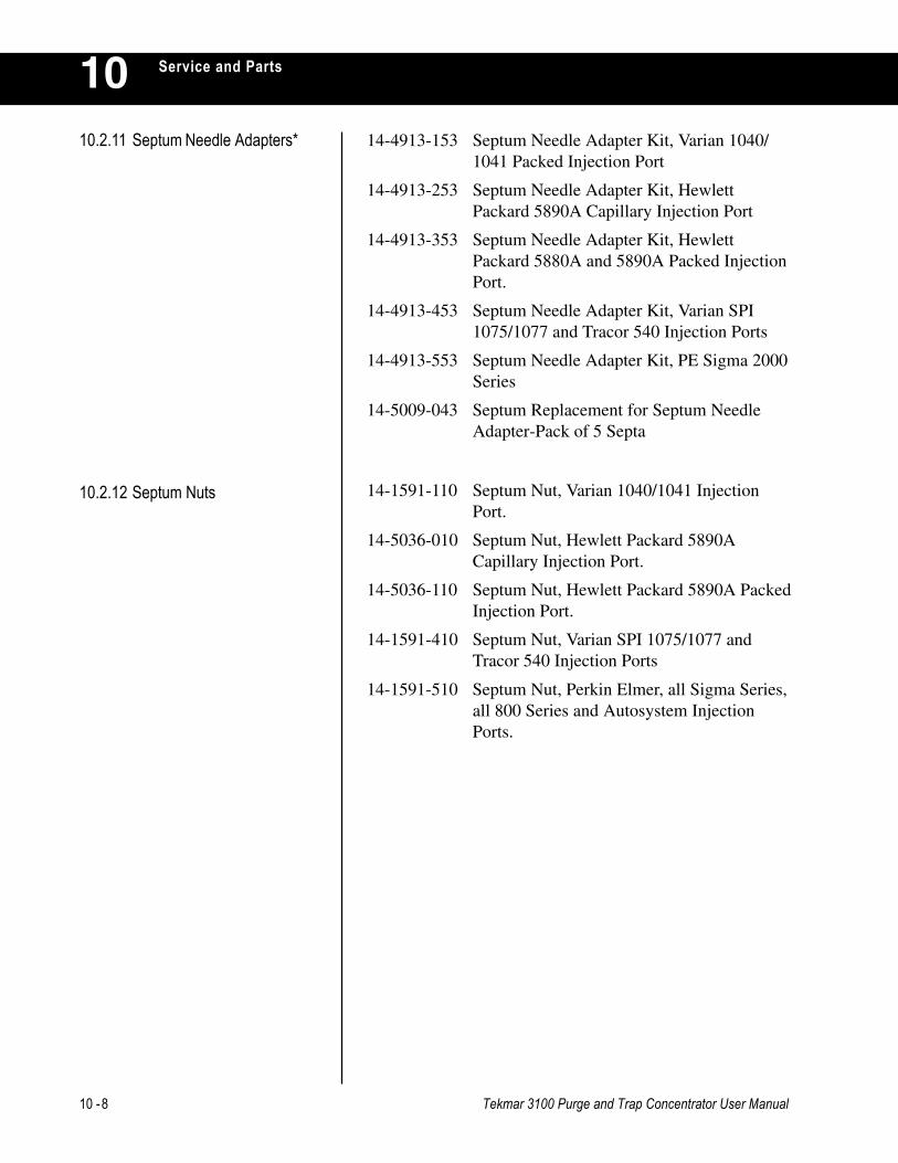
10 -8 Tekmar 3100 Purge and Trap Concentrator User Manual
Service and Parts1010.2.11 Septum Needle Adapters* 14-4913-153 Septum Needle Adapter Kit, Varian 1040/
1041 Packed Injection Port
14-4913-253 Septum Needle Adapter Kit, HewlettPackard 5890A Capillary Injection Port
14-4913-353 Septum Needle Adapter Kit, HewlettPackard 5880A and 5890A Packed InjectionPort.
14-4913-453 Septum Needle Adapter Kit, Varian SPI1075/1077 and Tracor 540 Injection Ports
14-4913-553 Septum Needle Adapter Kit, PE Sigma 2000Series
14-5009-043 Septum Replacement for Septum NeedleAdapter-Pack of 5 Septa
10.2.12 Septum Nuts 14-1591-110 Septum Nut, Varian 1040/1041 InjectionPort.
14-5036-010 Septum Nut, Hewlett Packard 5890ACapillary Injection Port.
14-5036-110 Septum Nut, Hewlett Packard 5890A PackedInjection Port.
14-1591-410 Septum Nut, Varian SPI 1075/1077 andTracor 540 Injection Ports
14-1591-510 Septum Nut, Perkin Elmer, all Sigma Series,all 800 Series and Autosystem InjectionPorts.
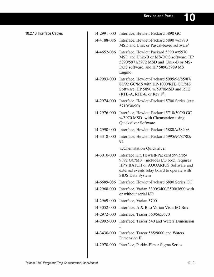
Tekmar 3100 Purge and Trap Concentrator User Manual 10 -9
Service and Parts 1014-2991-000 Interface, Hewlett-Packard 5890 GC
14-4188-086 Interface, Hewlett-Packard 5890 w/5970MSD and Unix or Pascal-based software1
14-4652-086 Interface, Hewlett Packard 5890 w/5970MSD and Unix-B or MS-DOS software, HP5890/5971/5972 MSD and Unix-B or MS-DOS software, and HP 5890/5989 MSEngine
14-2993-000 Interface, Hewlett-Packard 5995/96/85/87/88/92 GC/MS with HP-1000/RTE GC/MSSoftware, HP 5890 w/5970MSD and RTE(RTE-A, RTE-6, or Rev F2)
14-2974-000 Interface, Hewlett-Packard 5700 Series (exc.5710/30/90)
14-2976-000 Interface, Hewlett-Packard 5710/30/90 GCw/5970 MSD with Chemstation usingQuicksilver Software
14-2990-000 Interface, Hewlett-Packard 5880A/5840A
14-3318-000 Interface, Hewlett-Packard 5995/96/87/85/92
w/Chemstation-Quicksilver
14-3010-000 Interface Kit, Hewlett-Packard 5995/85/9392 GC/MS (includes I/O box). requiresHP’s BATCH or AQUARIUS Software andexternal events relay board to operate withSIDS Data System
14-6689-086 Interface, Hewlett-Packard 6890 Series GC
14-2968-000 Interface, Varian 3300/3400/3500/3600 withor without serial I/O
14-2969-000 Interface, Varian 3700
14-3052-000 Interface, A & B to Varian Vista I/O Box
14-2972-000 Interface, Tracor 560/565/670
14-2992-000 Interface, Tracor 540 and Waters DimensionI
14-3430-000 Interface, Tracor 585/9000 and WatersDimension II
14-2970-000 Interface, Perkin-Elmer Sigma Series
10.2.13 Interface Cables

10 -10 Tekmar 3100 Purge and Trap Concentrator User Manual
Service and Parts10
10.2.14 Miscellaneous
14-3233-000 Interface, Perkin-Elmer 8000 Series/Autosystem
14-2973-000 Interface, Shimadzu GC9A
14-4610-086 Interface, Shimadzu GC 14A/15A, GC 14Aw/QP 1000 EX MSD and GC 14A w/QP2000 MSD
14-4009-000 Interface Splicer Cable, Finnigan 5100/4000/4500 and OWA
14-4938-086 Interface, Carlo Erba Mega/Vega Series andFisons 8000
14-3147-000 Interface, General Purpose/HNU 301/321/4213
3 Valve driver option necessary from HNU.
14-5118-100 Kit, Solvent Flush
14-5959-000 Kit, Desorb, 1/4" x 7"
14-5525-019 Blower assembly, 60 CFM 115V
14-5524-219 Fan assembly, 3 1/8" SQ, 14" Leads
14-5524-319 Fan assembly, 3 1/8" SQ, 11" Leads
14-6000-217 Carton, Shipping, with Foam
14-3100-074 Manual, User, 3100
14-5765-176 TekLink, 3100
14-5306-185 Panel, Front, 3100

INDEX

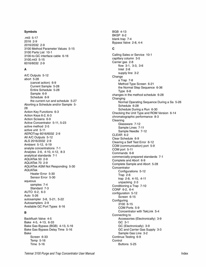
Tekmar 3100 Purge and Trap Concentrator User Manual Index
Index
Symbols
.mt3 5-172016 2-92016/2032 2-93100 Method Parameter Values 5-153100 Parts List 10-13100-to-GC interface cable 6-163100.mt3 5-156016/6032 2-9
A
A/C Outputs 5-12abort 5-28
(cancel action) 6-9Current Sample 5-28Entire Schedule 5-28Sample 6-9Schedule 6-9the current run and schedule 5-27
Aborting a Schedule and/or Sample 5-28Action Key Functions 6-3Action Keys 6-2, 6-3Action Screens 6-9Active Concentrator 5-11, 5-23active method 2-5active unit 5-11AEROTrap 6016/6032 2-9All A/C Outputs 5-12ALS 2016/2032 2-9Ambient 5-12, 6-19analyte concentrations 7-1Analytes 2-6, 4-10, 4-12, 8-3analytical standards 7-1AQUATek 50 2-9AQUATek 70 2-9AQUATek ASM Not Responding 5-30AQUATek
Heater Error 5-30Sensor Error 5-30
aqueoussamples 7-4Standard 7-3
AUTO 6-2, 6-3Auto 5-26autosampler 3-8, 5-21, 5-22Autosamplers 2-9Available GC Port Types 6-16
B
Backflush Valve 4-5Bake 4-5, 4-13, 6-33Bake Gas Bypass (BGB) 4-13, 5-16Bake Gas Bypass Delay Time 5-16Bake
Screen 6-33Temp 5-16Time 5-16
BGB 4-13BKSP 6-2blank trap 7-4Bypass Valve 2-8, 4-4
C
Calling Sales or Service 10-1capillary column 3-5Carrier gas 2-8
flow 3-1, 3-3, 3-6Inlet 2-8supply line 3-2
Changea Trap 7-8Method Type Screen 6-21the Normal Step Sequence 6-36Type 6-8
changes in the method schedule 6-28Changing
Normal Operating Sequence During a Sa 5-26Schedule 6-28Schedule During a Run 6-30
Checking the Unit Type and ROM Version 6-14chromatographic performance 8-3Cleaning
Glassware 7-12Sample Lines 7-11Sample Needle 7-12
CLEAR 6-2Clear Schedule 6-9Clearing a Self Test Error 6-12COM (communication) port 5-9COM port 5-11Commands 6-8commercially-prepared standards 7-1Complete and Abort 6-9Complete Sample and Abort 5-28Concentrator
Configurations 5-12Trap 2-6trap 2-8, 4-10, 4-11unpacking 2-3
Conditioning a Trap 7-10CONF 6-2, 6-4configuration 5-12
Screen 6-15Configuring
3100 6-15COM Ports 5-9Concentrator with TekLink 5-4
Connecting toAccessories (Electronically) 3-9GC 3-1GC (Electronically) 3-9GC and Carrier Gas Supply 3-3Sample Gas Line 3-2
Continue Testing 6-9Control
Buttons 5-25
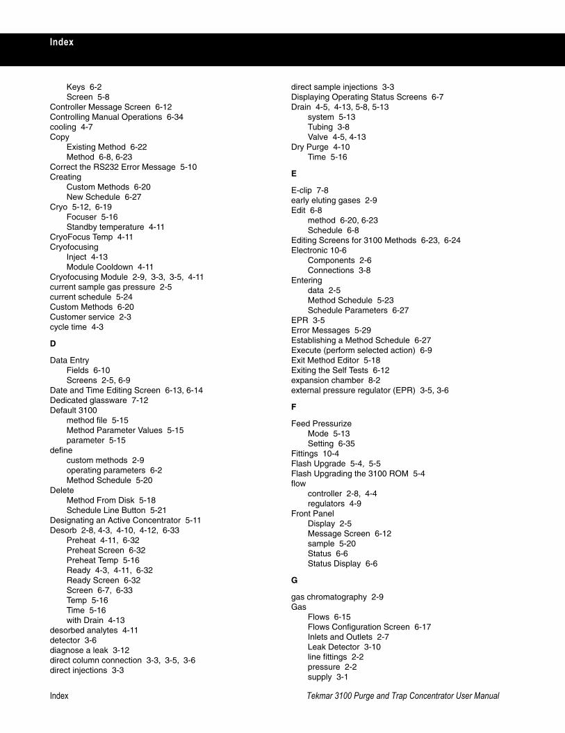
Index Tekmar 3100 Purge and Trap Concentrator User Manual
Index
Keys 6-2Screen 5-8
Controller Message Screen 6-12Controlling Manual Operations 6-34cooling 4-7Copy
Existing Method 6-22Method 6-8, 6-23
Correct the RS232 Error Message 5-10Creating
Custom Methods 6-20New Schedule 6-27
Cryo 5-12, 6-19Focuser 5-16Standby temperature 4-11
CryoFocus Temp 4-11Cryofocusing
Inject 4-13Module Cooldown 4-11
Cryofocusing Module 2-9, 3-3, 3-5, 4-11current sample gas pressure 2-5current schedule 5-24Custom Methods 6-20Customer service 2-3cycle time 4-3
D
Data EntryFields 6-10Screens 2-5, 6-9
Date and Time Editing Screen 6-13, 6-14Dedicated glassware 7-12Default 3100
method file 5-15Method Parameter Values 5-15parameter 5-15
definecustom methods 2-9operating parameters 6-2Method Schedule 5-20
DeleteMethod From Disk 5-18Schedule Line Button 5-21
Designating an Active Concentrator 5-11Desorb 2-8, 4-3, 4-10, 4-12, 6-33
Preheat 4-11, 6-32Preheat Screen 6-32Preheat Temp 5-16Ready 4-3, 4-11, 6-32Ready Screen 6-32Screen 6-7, 6-33Temp 5-16Time 5-16with Drain 4-13
desorbed analytes 4-11detector 3-6diagnose a leak 3-12direct column connection 3-3, 3-5, 3-6direct injections 3-3
direct sample injections 3-3Displaying Operating Status Screens 6-7Drain 4-5, 4-13, 5-8, 5-13
system 5-13Tubing 3-8Valve 4-5, 4-13
Dry Purge 4-10Time 5-16
E
E-clip 7-8early eluting gases 2-9Edit 6-8
method 6-20, 6-23Schedule 6-8
Editing Screens for 3100 Methods 6-23, 6-24Electronic 10-6
Components 2-6Connections 3-8
Enteringdata 2-5Method Schedule 5-23Schedule Parameters 6-27
EPR 3-5Error Messages 5-29Establishing a Method Schedule 6-27Execute (perform selected action) 6-9Exit Method Editor 5-18Exiting the Self Tests 6-12expansion chamber 8-2external pressure regulator (EPR) 3-5, 3-6
F
Feed PressurizeMode 5-13Setting 6-35
Fittings 10-4Flash Upgrade 5-4, 5-5Flash Upgrading the 3100 ROM 5-4flow
controller 2-8, 4-4regulators 4-9
Front PanelDisplay 2-5Message Screen 6-12sample 5-20Status 6-6Status Display 6-6
G
gas chromatography 2-9Gas
Flows 6-15Flows Configuration Screen 6-17Inlets and Outlets 2-7Leak Detector 3-10line fittings 2-2pressure 2-2supply 3-1
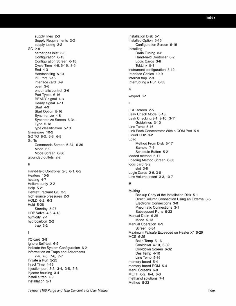
Tekmar 3100 Purge and Trap Concentrator User Manual Index
Index
supply lines 2-3Supply Requirements 2-2supply tubing 2-2
GC 2-8carrier gas inlet 3-3Configuration 6-15Configuration Screen 6-15Cycle Time 4-8, 5-16, 8-5End 4-3Handshaking 5-13I/O Port 6-15interface card 3-9oven 3-6pneumatic control 3-6Port Types 6-16READY signal 4-3Ready signal 4-11Start 4-3Start Option 5-16Synchronize 4-8Synchronize Screen 6-34Type 5-13type classification 5-13
Glassware 10-2GO TO 6-2, 6-3, 6-9Go To
Commands Screen 6-34, 6-36Mode 6-9Mode Screen 6-36
grounded outlets 2-2
H
Hand-Held Controller 2-5, 6-1, 6-2 Heaters 10-5heating 4-7Helium purity 2-2Help 5-21Hewlett Packard GC 3-5high source pressures 2-3HOLD 6-2, 6-3Hold 5-26
Standby 5-27HRP Valve 4-5, 4-13humidity 2-1hydrocarbon 2-2
trap 3-2
I
I/O card 3-8Ignore Self-test 6-9Indicate the System Configuration 6-21Information on Traps and Adsorbents
7-4, 7-5, 7-6, 7-7Initiate a Run 5-25Inject Time 4-13injection port 3-3, 3-4, 3-5, 3-6injector housing 3-4install a trap 7-9Installation 2-1
Installation Disk 5-1Installed Option 6-15
Configuration Screen 6-19Installing
Drain Tubing 3-8Hand-held Controller 6-2Logic Cards 3-8TekLink 5-1
instrument configuration 5-12Interface Cables 10-9internal trap 2-8Interrupting a Run 6-35
K
keypad 6-1
L
LCD screen 2-5Leak Check Mode 5-13Leak Checking 3-1, 3-10, 3-11
Guidelines 3-10Line Temp 5-16Link Each Concentrator With a COM Port 5-9Liquid CO2 8-2Load
Method From Disk 5-17Sample 7-4Schedule Button 5-21
loaded method 5-17Loading Method Screen 6-33logic card 3-9
slot 3-8Logic Cards 2-6, 3-8Low Volume Insert 3-3, 10-7
M
MakingBackup Copy of the Installation Disk 5-1Direct Column Connection Using an Externa 3-5Electronic Connections 3-8Pneumatic Connections 3-1Subsequent Runs 6-33
Manual Drain 6-35Mode 5-13
Manual Operation 6-9Screen 6-34
Maximum Failsafe Exceeded on Heater X* 5-29MCS 6-25
Bake Temp 5-16Cooldown 4-10, 6-32Cooldown Screen 6-32Des Temp 4-10Line Temp 5-16
memory board 5-4memory board ROM 5-4Menu Screens 6-8METH 6-2, 6-4, 6-8methanol solutions 7-1Method 5-23
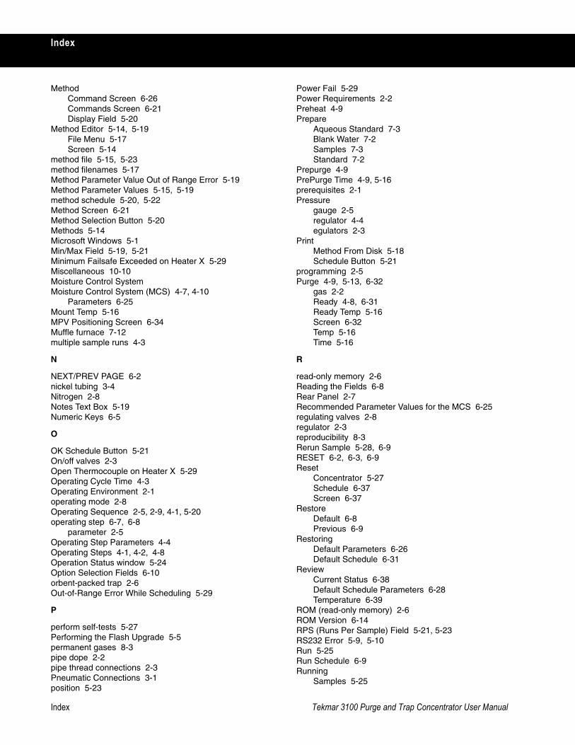
Index Tekmar 3100 Purge and Trap Concentrator User Manual
Index
MethodCommand Screen 6-26Commands Screen 6-21Display Field 5-20
Method Editor 5-14, 5-19File Menu 5-17Screen 5-14
method file 5-15, 5-23method filenames 5-17Method Parameter Value Out of Range Error 5-19Method Parameter Values 5-15, 5-19method schedule 5-20, 5-22Method Screen 6-21Method Selection Button 5-20Methods 5-14Microsoft Windows 5-1Min/Max Field 5-19, 5-21Minimum Failsafe Exceeded on Heater X 5-29Miscellaneous 10-10Moisture Control System Moisture Control System (MCS) 4-7, 4-10
Parameters 6-25Mount Temp 5-16MPV Positioning Screen 6-34Muffle furnace 7-12multiple sample runs 4-3
N
NEXT/PREV PAGE 6-2nickel tubing 3-4Nitrogen 2-8Notes Text Box 5-19Numeric Keys 6-5
O
OK Schedule Button 5-21On/off valves 2-3Open Thermocouple on Heater X 5-29Operating Cycle Time 4-3Operating Environment 2-1operating mode 2-8Operating Sequence 2-5, 2-9, 4-1, 5-20operating step 6-7, 6-8
parameter 2-5Operating Step Parameters 4-4Operating Steps 4-1, 4-2, 4-8Operation Status window 5-24Option Selection Fields 6-10orbent-packed trap 2-6Out-of-Range Error While Scheduling 5-29
P
perform self-tests 5-27Performing the Flash Upgrade 5-5permanent gases 8-3pipe dope 2-2pipe thread connections 2-3Pneumatic Connections 3-1position 5-23
Power Fail 5-29Power Requirements 2-2Preheat 4-9Prepare
Aqueous Standard 7-3Blank Water 7-2Samples 7-3Standard 7-2
Prepurge 4-9PrePurge Time 4-9, 5-16prerequisites 2-1Pressure
gauge 2-5regulator 4-4egulators 2-3
PrintMethod From Disk 5-18Schedule Button 5-21
programming 2-5Purge 4-9, 5-13, 6-32
gas 2-2Ready 4-8, 6-31Ready Temp 5-16Screen 6-32Temp 5-16Time 5-16
R
read-only memory 2-6Reading the Fields 6-8Rear Panel 2-7Recommended Parameter Values for the MCS 6-25regulating valves 2-8regulator 2-3reproducibility 8-3Rerun Sample 5-28, 6-9RESET 6-2, 6-3, 6-9Reset
Concentrator 5-27Schedule 6-37Screen 6-37
RestoreDefault 6-8Previous 6-9
RestoringDefault Parameters 6-26Default Schedule 6-31
ReviewCurrent Status 6-38Default Schedule Parameters 6-28Temperature 6-39
ROM (read-only memory) 2-6ROM Version 6-14RPS (Runs Per Sample) Field 5-21, 5-23RS232 Error 5-9, 5-10Run 5-25Run Schedule 6-9Running
Samples 5-25
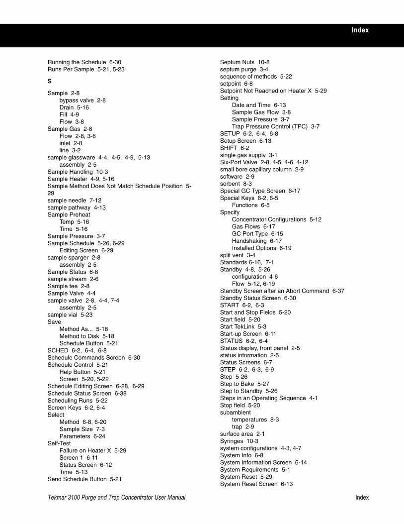
Tekmar 3100 Purge and Trap Concentrator User Manual Index
Index
Running the Schedule 6-30Runs Per Sample 5-21, 5-23
S
Sample 2-8bypass valve 2-8Drain 5-16Fill 4-9Flow 3-8
Sample Gas 2-8Flow 2-8, 3-8inlet 2-8line 3-2
sample glassware 4-4, 4-5, 4-9, 5-13assembly 2-5
Sample Handling 10-3Sample Heater 4-9, 5-16Sample Method Does Not Match Schedule Position 5-29sample needle 7-12sample pathway 4-13Sample Preheat
Temp 5-16Time 5-16
Sample Pressure 3-7Sample Schedule 5-26, 6-29
Editing Screen 6-29sample sparger 2-8
assembly 2-5Sample Status 6-8sample stream 2-6Sample tee 2-8Sample Valve 4-4sample valve 2-8, 4-4, 7-4
assembly 2-5sample vial 5-23Save
Method As... 5-18Method to Disk 5-18Schedule Button 5-21
SCHED 6-2, 6-4, 6-8Schedule Commands Screen 6-30Schedule Control 5-21
Help Button 5-21Screen 5-20, 5-22
Schedule Editing Screen 6-28, 6-29Schedule Status Screen 6-38Scheduling Runs 5-22Screen Keys 6-2, 6-4Select
Method 6-8, 6-20Sample Size 7-3Parameters 6-24
Self-TestFailure on Heater X 5-29Screen 1 6-11Status Screen 6-12Time 5-13
Send Schedule Button 5-21
Septum Nuts 10-8septum purge 3-4sequence of methods 5-22setpoint 6-8Setpoint Not Reached on Heater X 5-29Setting
Date and Time 6-13Sample Gas Flow 3-8Sample Pressure 3-7Trap Pressure Control (TPC) 3-7
SETUP 6-2, 6-4, 6-8Setup Screen 6-13SHIFT 6-2single gas supply 3-1Six-Port Valve 2-8, 4-5, 4-6, 4-12small bore capillary column 2-9software 2-9sorbent 8-3Special GC Type Screen 6-17Special Keys 6-2, 6-5
Functions 6-5Specify
Concentrator Configurations 5-12Gas Flows 6-17GC Port Type 6-15Handshaking 6-17Installed Options 6-19
split vent 3-4Standards 6-16, 7-1Standby 4-8, 5-26
configuration 4-6Flow 5-12, 6-19
Standby Screen after an Abort Command 6-37Standby Status Screen 6-30START 6-2, 6-3Start and Stop Fields 5-20Start field 5-20Start TekLink 5-3Start-up Screen 6-11STATUS 6-2, 6-4Status display, front panel 2-5status information 2-5Status Screens 6-7STEP 6-2, 6-3, 6-9Step 5-26Step to Bake 5-27Step to Standby 5-26Steps in an Operating Sequence 4-1Stop field 5-20subambient
temperatures 8-3trap 2-9
surface area 2-1Syringes 10-3system configurations 4-3, 4-7System Info 6-8System Information Screen 6-14System Requirements 5-1System Reset 5-29System Reset Screen 6-13
Index Tekmar 3100 Purge and Trap Concentrator User Manual
Index
T
tee union 3-2TEK3100 5-2TekLink 3100 2-9, 5-1, 5-3
installation 5-1software 2-9
Tekmar Identification Screen 6-11Temp Zone Status 5-24Temperature
Parameter Display 6-6Screen 6-39setpoint 4-7, 6-8value 6-8Zone Status 5-24
temperature-dependent steps 6-8TEMPS 6-2, 6-4Time and Temperature Parameters 4-7Time Parameter Display 6-7Time/Date 6-8timed steps 6-8timer 5-26TPC 2-8
valve 2-8, 4-7transfer line 2-8, 3-6trap 4-5, 7-8Trap lifetime 7-9Trap Pressure Control (TPC) 2-8, 3-7
valve 2-8, 4-7effects 5-13
Trap Pressure gauge 2-5Trap Region Type 5-12trap sorbent 8-3Traps 10-3TTL
active-high signals 6-16active-low signals 6-16
Tubing 10-3Turbo Cool Temp 5-16TURBO Cooldown 4-9, 8-6TURBOCool 2-9, 4-3, 4-8, 5-12, 6-19, 8-1
Applications 8-3Method Parameters 8-5Operation 8-2Operating Cycle Times 8-5Specifications and Safety 8-4Temperature 8-5trap 8-5
U
ultra-high purity helium 2-8Ultrasonic bath 7-12Understanding Operating Steps 4-8union 3-4, 3-6Unit Type 6-14Unpacking 2-1Update Schedule 6-9User 6-16User GC Type 5-13Using GC Regulated Carrier Gas 3-3
Using Methods 5-14Using Screens 6-6Using Standards 7-1Using the Editing Screens 6-23
V
valves 2-8configurations 4-4, 4-11Settings 4-4Temp 5-16
Valves and Pneumatics 10-6Variable Function Keys 6-2
options 6-8Vent Valve 4-5vial positions 5-21volatile
analytes 2-8materials 2-2
W
When to Replace a Trap 7-10Working with Traps 7-4