telecommunications network standards · pdf filetelecommunications network standards and...
TRANSCRIPT

TELECOMMUNICATIONS NETWORK STANDARDS AND GUIDELINES
TELECOMMUNICATIONS NETWORK STANDARDS
AND GUIDELINES
FOR THE NEW ADMINISTRATION BULDING
October 1998
TELECOMMUNICATIONS NETWORK STANDARDS AND GUIDELINES
Table of Contents
SECTION I: New Construction Programming1.0 New Construction
1.1 Design Elements . . . . . . . . . . . . . . . . . . . . . . . . . . . . . . . . . . 1-11.1.1 Spaces . . . . . . . . . . . . . . . . . . . . . . . . . . . . . . . . . . 1-11.1.2 Pathways . . . . . . . . . . . . . . . . . . . . . . . . . . . . . . . . . . 1-11.1.3 Telecommunication Spaces . . . . . . . . . . . . . . . . . . . . 1-2
1.1.3.1 Service Entrance Room . . . . . . . . . . . . . . . . 1-21.1.3.2 Equipment Room . . . . . . . . . . . . . . . . . . . . . . 1-31.1.3.3 Telecommunication Closet . . . . . . . . . . . . . . 1-4
1.1.4 Telecommunications Pathway . . . . . . . . . . . . . . . . . . . . 1-41.1.4.1 Interbuilding Distribution System . . . . . . . . . . 1-41.1.4.2 Intra-building Backbone (Riser) . . . . . . . . . . 1-5
1.1.5 Horizontal Cabling . . . . . . . . . . . . . . . . . . . . . . . . . . . . 1-51.1.5.1 Station Outlet . . . . . . . . . . . . . . . . . . . . . . . . . 1-6
1.2 Design Issues1.2.1 Office Spaces . . . . . . . . . . . . . . . . . . . . . . . . . . . . . . . . . 1-61.2.2 Conference Rooms . . . . . . . . . . . . . . . . . . . . . . . . . . . 1-6
1.3 Summary . . . . . . . . . . . . . . . . . . . . . . . . . . . . . . . . . . 1-7
SECTION II: Infrastructure and Pathways Details2.0 Infrastructure Details
2.1 Telecommunications Spaces . . . . . . . . . . . . . . . . . . . . . . . . . . . . . . 2-12.1.1 Building Service entrance . . . . . . . . . . . . . . . . . . . . . . . . . 2-1
2.1.1.1 Space Design . . . . . . . . . . . . . . . . . . . . . . . . . 2-12.1.2 Equipment Room . . . . . . . . . . . . . . . . . . . . . . . . . . . . . . 2-3
2.1.2.1 Space Design . . . . . . . . . . . . . . . . . . . . . . . . . 2-32.1.3 Telecommunications Closet . . . . . . . . . . . . . . . . . . . . . . . . . 2-5
2.1.3.1 Space Design . . . . . . . . . . . . . . . . . . . . . . . . . 2-5
2.2 Telecommunications Pathways . . . . . . . . . . . . . . . . . . . . . . . . . . . . . 2-72.2.1 Conduit and Manhole System . . . . . . . . . . . . . . . . . . . . . . . . 2-82.2.2 Intra-building Backbone . . . . . . . . . . . . . . . . . . . . . . . . . . . . . 2-92.2.3 Sizing . . . . . . . . . . . . . . . . . . . . . . . . . . . . . . . . . . . . . 2-92.2.4 Design . . . . . . . . . . . . . . . . . . . . . . . . . . . . . . . . . . . . . 2-102.2.5 Horizontal Pathways . . . . . . . . . . . . . . . . . . . . . . . . . . . . . . . 2-102.2.6 Cable Tray . . . . . . . . . . . . . . . . . . . . . . . . . . . . . . . . . . . . . 2-102.2.7 Station Outlets . . . . . . . . . . . . . . . . . . . . . . . . . . . . . . . . . . . 2-112.2.8 Faceplates . . . . . . . . . . . . . . . . . . . . . . . . . . . . . . . . . . . 2-132.2.9 Surface Mount Boxes . . . . . . . . . . . . . . . . . . . . . . . . . . . . . 2-13
Appendix A Service Entrance & Equipment Room layouts . . . . . . . . . . . 2-14Appendix B Telecommunications Closet layout . . . . . . . . . . . . . . . . . . . 2-15Appendix C Flow-Fill non-shrink Backfill . . . . . . . . . . . . . . . . . . . . . . . . 2-16
TELECOMMUNICATIONS NETWORK STANDARDS AND GUIDELINES
Appendix D Pull Box Sizing . . . . . . . . . . . . . . . . . . . . . . . . . . . . . . . . . . . 2-17Appendix E Station Labeling . . . . . . . . . . . . . . . . . . . . . . . . . . . . . . . . . 2-18
SECTION III: Wire, Cable, & Support Systems3.0 Wire, Cable, and Support Systems . . . . . . . . . . . . . . . . . . . . . . . . . . . . . . 3-1
3.1 Copper Cable Systems . . . . . . . . . . . . . . . . . . . . . . . . . . . . . . . . . . . . 3-23.1.1 Station Cable . . . . . . . . . . . . . . . . . . . . . . . . . . . . . . . . . . . . . . . . . . 3-33.1.2 Station Jacks . . . . . . . . . . . . . . . . . . . . . . . . . . . . . . . . . . . . . . . . . . 3-33.1.3 Riser Cable . . . . . . . . . . . . . . . . . . . . . . . . . . . . . . . . . . . . . . . . . . 3-43.1.4 Inter-building Cable . . . . . . . . . . . . . . . . . . . . . . . . . . . . . . . . . . . . . . . 3-43.1.5 Cable Routing . . . . . . . . . . . . . . . . . . . . . . . . . . . . . . . . . . . . . . . . . . 3-53.1.6 Cable Termination . . . . . . . . . . . . . . . . . . . . . . . . . . . . . . . . . . . . . . . 3-5
3.1.6.1 Blocks . . . . . . . . . . . . . . . . . . . . . . . . . . . . . . . . . . . . . . . 3-53.1.6.2 Modular Patch Panel . . . . . . . . . . . . . . . . . . . . . . . . . . . . 3-5
3.1.7 Cable Protection . . . . . . . . . . . . . . . . . . . . . . . . . . . . . . . . . . . . . . . 3-63.1.8 Splice Cases . . . . . . . . . . . . . . . . . . . . . . . . . . . . . . . . . . . . . . . . . . 3-7
3.2 Fiber Optic Cable Systems3.2.2 Fiber Riser Cable . . . . . . . . . . . . . . . . . . . . . . . . . . . . . . . . . . . . . . . 3-73.2.3 Inter-building Fiber Cable . . . . . . . . . . . . . . . . . . . . . . . . . . . . . . . 3-83.2.4 Fiber Optic Patch Panels . . . . . . . . . . . . . . . . . . . . . . . . . . . . . . . 3-83.2.5 Fiber Optic Interconnect Centers, Panels and Trays . . . . . . . . . . . 3-9
3.2.5.1 Wall Mount . . . . . . . . . . . . . . . . . . . . . . . . . . . . . . . . . 3-93.2.5.2 Rack Mounted High Density Fiber Interconnect Center . . . 3-103.2.5.3 Rack Mounted Low Profile Fiber Connect Panel . . . . . . 3-103.2.5.4 Rack Mounted Fiber Tray . . . . . . . . . . . . . . . . . . . . . . . 3-10
3.3 Cross Connect Wire and Patch Cords3.3.1 Cross Connect Wire . . . . . . . . . . . . . . . . . . . . . . . . . . . . . . . . . . . . 3-113.3.2 Patch Cords . . . . . . . . . . . . . . . . . . . . . . . . . . . . . . . . . . . . . . . 3-11
3.3.2.1 Modular patch Cords: Category 5 . . . . . . . . . . . . . . . . . . . 3-113.3.2.2 110 patch Cords: Category 5 . . . . . . . . . . . . . . . . . . . 3-123.3.2.3 Modular Patch Cords: Category 5 . . . . . . . . . . . . . . 3-123.3.2.4 Fiber patch Cords (Jumpers) . . . . . . . . . . . . . . . . . . . . . . 3-12
3.4 Coaxial Cable Systems . . . . . . . . . . . . . . . . . . . . . . . . . . . . . . . . . . . . . . . 3-133.4.1 Inter-building Cable . . . . . . . . . . . . . . . . . . . . . . . . . . . . . . . . . . . . 3-143.4.2 Riser Cable . . . . . . . . . . . . . . . . . . . . . . . . . . . . . . . . . . . . . . . 3-143.4.3 Station Cable . . . . . . . . . . . . . . . . . . . . . . . . . . . . . . . . . . . . . . . . . . 3-14
SECTION IV: Planning & Design4.0 Design Process
4.1 Construction process . . . . . . . . . . . . . . . . . . . . . . . . . . . . . . . . . . . . 4-14.2 Planning – Form A . . . . . . . . . . . . . . . . . . . . . . . . . . . . . . . . . . . . 4-24.3 Procurement Specifications . . . . . . . . . . . . . . . . . . . . . . . . . . . . . . 4-3
4.3.1 Materials . . . . . . . . . . . . . . . . . . . . . . . . . . . . . . . . . . . . . . . . . 4-3

TELECOMMUNICATIONS NETWORK STANDARDS AND GUIDELINES
4.3.1.1 Cable . . . . . . . . . . . . . . . . . . . . . . . . . . . . . . . . . 4-34.3.1.2 Copper and Fiber Hardware . . . . . . . . . . . . . 4-64.3.1.3 Video Distribution System . . . . . . . . . . . . . . . . 4-8
SECTION V: Installation and Acceptance Testing5.0 Installation
5.0.1 Installation of Station Cables . . . . . . . . . . . . . . . . . . . . . . . . . . . . . . 5-15.0.2 Installation of Copper Riser Cables . . . . . . . . . . . . . . . . . . . . . . 5-25.0.3 Installation of Station/Riser/Tile cable Jumper Wires . . . . . . . . . . . 5-25.0.4 Installation of Inter-building Copper Cable . . . . . . . . . . . . . . . . . . . . 5-25.0.5 Installation of Copper Cable Splices . . . . . . . . . . . . . . . . . . . . . . . 5-25.0.6 Installation of Innerduct . . . . . . . . . . . . . . . . . . . . . . . . . . . . . . . . . . 5-35.0.7 Installation of Inter-building Fiber Optic Cable . . . . . . . . . . . . . . . . . 5-35.0.8 Installation of Fiber Optic Riser Cable . . . . . . . . . . . . . . . . . . . . . . . 5-35.0.9 Conduit Trenching, Backfill, and Driveway Restoral . . . . . . . . . . . 5-45.0.10 Installation Management . . . . . . . . . . . . . . . . . . . . . . . . . . . . . . . . . . 5-45.0.11 Acceptance Testing . . . . . . . . . . . . . . . . . . . . . . . . . . . . . . . . . . . . . 5-45.0.12 Documentation . . . . . . . . . . . . . . . . . . . . . . . . . . . . . . . . . . . . . . . . . . . 5-4
5.1 Acceptance Testing5.1.1 Inspection Procedures . . . . . . . . . . . . . . . . . . . . . . . . . . . . . . . . . . . . . 5-55.1.2 Acceptance Testing Procedures . . . . . . . . . . . . . . . . . . . . . . . . . . 5-5
5.1.2.1 Copper station and Riser Cable . . . . . . . . . . . . . . . . . . . . 5-65.1.2.2 Fiber . . . . . . . . . . . . . . . . . . . . . . . . . . . . . . . . . . . . . . . . . . . 5-75.1.2.3 Video Distribution System . . . . . . . . . . . . . . . . . . . . . . . . . . 5-8
5.2 Documentation . . . . . . . . . . . . . . . . . . . . . . . . . . . . . . . . . . . . . . . . . . . . 5-10
SECTION VI: Hardware Specifications and Installation6.0 Hardware Specifications and Installation
6.0.1 Fiber Serviced Building6.0.1.1 Ethernet Switch . . . . . . . . . . . . . . . . . . . . . . . . . . . . . . . . . . . 6-16.0.1.2 Hubs . . . . . . . . . . . . . . . . . . . . . . . . . . . . . . . . . . . . . . . . . 6-16.0.1.3 Phones . . . . . . . . . . . . . . . . . . . . . . . . . . . . . . . . . . . . . . . . . 6-16.0.1.4 Other Voice Services . . . . . . . . . . . . . . . . . . . . . . . . . . . 6-26.0.1.5 Disaster Recovery (Minor/Major Scenarios) . . . . . . . . 6-2
TELECOMMUNICATIONS NETWORK STANDARDS AND GUIDELINES
SECTION I: NEW CONSTRUCTION PROGRAMMING
1.0 NEW CONSTRUCTION
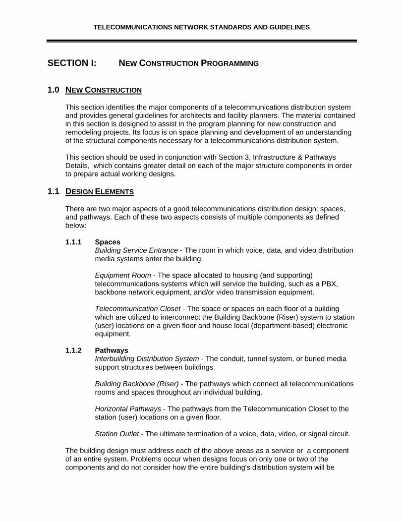
This section identifies the major components of a telecommunications distribution systemand provides general guidelines for architects and facility planners. The material containedin this section is designed to assist in the program planning for new construction andremodeling projects. Its focus is on space planning and development of an understandingof the structural components necessary for a telecommunications distribution system.
This section should be used in conjunction with Section 3, Infrastructure & PathwaysDetails, which contains greater detail on each of the major structure components in orderto prepare actual working designs.
1.1 DESIGN ELEMENTS
There are two major aspects of a good telecommunications distribution design: spaces,and pathways. Each of these two aspects consists of multiple components as definedbelow:
1.1.1 SpacesBuilding Service Entrance - The room in which voice, data, and video distributionmedia systems enter the building.
Equipment Room - The space allocated to housing (and supporting)telecommunications systems which will service the building, such as a PBX,backbone network equipment, and/or video transmission equipment.
Telecommunication Closet - The space or spaces on each floor of a buildingwhich are utilized to interconnect the Building Backbone (Riser) system to station(user) locations on a given floor and house local (department-based) electronicequipment.
1.1.2 PathwaysInterbuilding Distribution System - The conduit, tunnel system, or buried mediasupport structures between buildings.
Building Backbone (Riser) - The pathways which connect all telecommunicationsrooms and spaces throughout an individual building.
Horizontal Pathways - The pathways from the Telecommunication Closet to thestation (user) locations on a given floor.
Station Outlet - The ultimate termination of a voice, data, video, or signal circuit.
The building design must address each of the above areas as a service or a componentof an entire system. Problems occur when designs focus on only one or two of thecomponents and do not consider how the entire building's distribution system will be

TELECOMMUNICATIONS NETWORK STANDARDS AND GUIDELINES
utilized. For example, it is not enough to provide a cable tray in the building design; thetray must be of a usable type, be properly installed, be routed to the best advantage of thecable, and be interconnected with the Telecommunication Closets. Examples of potentialproblems include cable tray designs with lids that cannot be opened, HVAC and waterpipes in and through the tray, trays over fixed ceilings, and Telecommunication Closetswhich are separated from the tray by a fire-rated wall (without a pathway.)
Avoid designing a building in which the cable installer will be required to drill holes in wallsand place sleeves through fire partitions. While technology will change between the time ofthe initial architectural planning and building occupancy, the infrastructure (pathways andspaces) will be in place for the life of the building and must be capable of supportingmultiple changes in technology.
1.1.3 Telecommunications SpacesThe term "telecommunications spaces" refers not only to specific rooms but insome cases to space dedicated to telecommunications services in a roomdesignated for other uses.
There are three main categories of spaces as previously defined: ServiceEntrance, Equipment Room, and the Telecommunication Closet. Each area hasa distinct function; however, all are very inter-dependent. In some cases a singlespace can fulfill the function of all three spaces; however, it must be emphasizedthat the size and environmental support requirements are additive. If a buildingrequires 150 square feet for an equipment room, 50 feet cannot be provided byspace designated as a service entrance.
1.1.3.1 Service Entrance RoomThe Service Entrance is a room in which outside cable is terminatedand interconnected with the backbone (data and/or voice) cable usedthroughout the building. It provides facilities for large splicecontainers, cable termination mountings, and possibly electricalprotectors. This space is in addition to any space required for networkswitching equipment or active system components.
This space should be located on a lower level and within 50 feet of anoutside wall, allowing direct access by the entrance conduit.Consideration should be given to locating this space adjacent to anyequipment rooms or backbone (riser) spaces, which might berequired. Although two or even all three of these functions can becombined in a single space, adequate wall space must be provided.Design and location of room should also take into consideration theroute and placement of the City’s fiber/copper backbone connectingbuildings.
The Service Entrance room must be dry, not subject to flooding, andfree of overhead water, steam, or drain pipes.
Access to the room should be provided directly from a central hallway,not through another room. The Service Entrance room must be adedicated, enclosed room.
TELECOMMUNICATIONS NETWORK STANDARDS AND GUIDELINES
The minimum floor space requirements are five (5) feet by seven (7)feet.
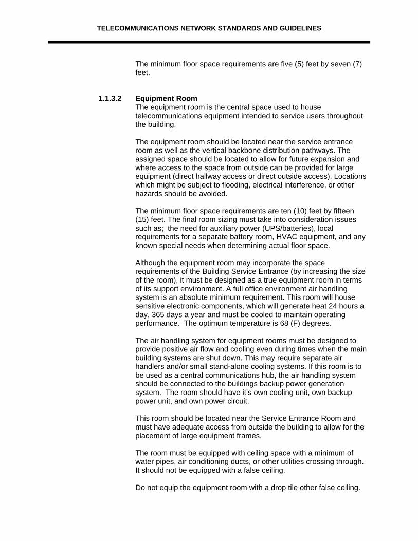
1.1.3.2 Equipment RoomThe equipment room is the central space used to housetelecommunications equipment intended to service users throughoutthe building.
The equipment room should be located near the service entranceroom as well as the vertical backbone distribution pathways. Theassigned space should be located to allow for future expansion andwhere access to the space from outside can be provided for largeequipment (direct hallway access or direct outside access). Locationswhich might be subject to flooding, electrical interference, or otherhazards should be avoided.
The minimum floor space requirements are ten (10) feet by fifteen(15) feet. The final room sizing must take into consideration issuessuch as; the need for auxiliary power (UPS/batteries), localrequirements for a separate battery room, HVAC equipment, and anyknown special needs when determining actual floor space.
Although the equipment room may incorporate the spacerequirements of the Building Service Entrance (by increasing the sizeof the room), it must be designed as a true equipment room in termsof its support environment. A full office environment air handlingsystem is an absolute minimum requirement. This room will housesensitive electronic components, which will generate heat 24 hours aday, 365 days a year and must be cooled to maintain operatingperformance. The optimum temperature is 68 (F) degrees.
The air handling system for equipment rooms must be designed toprovide positive air flow and cooling even during times when the mainbuilding systems are shut down. This may require separate airhandlers and/or small stand-alone cooling systems. If this room is tobe used as a central communications hub, the air handling systemshould be connected to the buildings backup power generationsystem. The room should have it’s own cooling unit, own backuppower unit, and own power circuit.
This room should be located near the Service Entrance Room andmust have adequate access from outside the building to allow for theplacement of large equipment frames.
The room must be equipped with ceiling space with a minimum ofwater pipes, air conditioning ducts, or other utilities crossing through.It should not be equipped with a false ceiling.
Do not equip the equipment room with a drop tile other false ceiling.

TELECOMMUNICATIONS NETWORK STANDARDS AND GUIDELINES
1.1.3.3. Telecommunication ClosetThe telecommunication closet is the space that supports the cableand equipment necessary for transmission between the building'sbackbone system and user (station) locations. This room was formallyknown as a "telephone closet"; a term that is very misleading.Although that term is still in use today within the construction industryand in some telecommunications standards documentation, the Cityhas adopted the more descriptive "Telecommunication Closet".
This space is called upon to terminate not only the cable from stationoutlets and backbone (riser) systems, but is also expected to houseand support local area network equipment, multiplexing equipment,video distribution equipment, and system monitoring components.Individual departments frequently need to install components in thesespaces to support advanced workstations or local computing needs.Space for such equipment is frequently not designed into office space,and the hardware is more cost effectively connected within the closetcompared to its placement in user spaces.
In addition to the actual floor space needs, the cost of the advancedelectronics required to support technology today should be taken intoconsideration when planning for these spaces. If multiple rooms on asingle floor are being considered because it is difficult to find a centralspace, the costs of installing and operating additional data hubsshould be weighed against the additional construction costs requiredto locate the room near the center of the building. These rooms mustbe stacked and should be centrally located within the buildingreducing the distance from the room to all user locations.
The Telecommunication Closet(s) serving an individual floor must beof sufficient size to support an extensive list of voice, data, and videoequipment. This room must be dedicated to telecommunications andmust be at least five (5) feet by Seven (7) feet in size.
1.1.4 Telecommunications PathwaysPathways refer to the facilities and supporting structures used to transporttelecommunications media from one location to another. It is important to think interms of pathways as more than simply conduit in order to properly design theseportions of the distribution system.
1.1.4.1 Interbuilding Distribution SystemThe designer must consider where the distribution system originatesand determine what is required to make it meet the needs of the newconstruction. The City has 12 strands of dark fiber and 100 paircopper cable sitting in a vault in the North-west corner of LaPorte andHowes. Both of these media will need to be taken to the newAdministration Building and terminated.

TELECOMMUNICATIONS NETWORK STANDARDS AND GUIDELINES
Although most design projects for individual City buildings do notspecifically address communications outside the building, care mustbe taken in developing plans for making connections to theseresources. In some cases, a separate construction and/or installationcontract might be required to provide adequate pathways up to thepoint at which the building project can be interconnected.
1.1.4.2 Intra-Building Backbone (Riser)In general this is the path used for placement of telecommunicationsmedia between the Service Entrance, Equipment Rooms,Telecommunication Closets, and Station Outlets. These pathwaysmust typically support copper, fiber optic, and coaxial cables servingequipment and will be cross-connected to end-users located on eachfloor of the building.
1.1.5 Horizontal CablingThe horizontal pathways between the Telecommunication Closet and the stationoutlet locations receive the heaviest usage and the most complaints of anycomponent of a telecommunications distribution system. It is an area with asignificant number of alternatives and one which frequently falls victim to budgetcuts. When working on this issue, the building designer should identify methodsfor placing and supporting both the initial station cable and future cable additions.
Cable trays installed over fixed ceilings are worthless once the ceiling iscomplete. Trays which require an installer to manipulate and open a lid everythree to four feet, in order to place cable, will not be used once the initialinstallation is complete. Floor trench, duct systems, and raised floors do notstand up well to floor care services and inevitability foster broken tiles, missingscrews, and flooded ducts. Dedicated conduit runs and floor mount poke throughare expensive and very inflexible in meeting the changing demands ofinstructional technology.
Our preferred horizontal distribution method is a flexible cable tray used inconjunction with plenum cable in the false ceiling.
Every Telecommunication Closet must provide a minimum of twice the amount ofhorizontal pathway access as is required to support the initial installation. Acloset, which is served by four (4) four-inch backbone conduits, should not beequipped with a single two-inch horizontal pathway conduit.
Any outlet separated from the main horizontal support system (such as a tray) bya fire or smoke partition must be provided a rated pathway such as a sleeve,which can be fire-stopped after cable is installed, or an enclosed conduit orraceway directly from the outlet to the tray side of the partition.
Every room must be designed with a specific pathway from the false ceiling areaused to access user locations to the main horizontal distribution pathway (suchas the cable tray.)

TELECOMMUNICATIONS NETWORK STANDARDS AND GUIDELINES
1.1.5.1 Station OutletThe station outlet will ultimately be configured to serve a variety ofdifferent telecommunications needs. An outlet which today may onlyrequire a voice connection may easily require multi-media data andvideo by the time the building construction is complete.
The prime point to remember about the station outlet is the need todesign outlet locations for future needs, not just today's applications. Ifthey are not initially required, they can be capped and used at a latertime. By paying attention to potential telecommunications locationsand the route by which they are served, the designer can savesignificant time and future costs from later attempts to meet changingneeds. Station conduit will be a minimum of one-half inch, and is tobe stubbed into the ceiling space.
1.2 DESIGN ISSUES
In addition to the Telecommunications Industry space and pathway issues, there are avariety of environment-specific issues that must be factored into the design of a newfacility. Significant changes are taking place in how information is being delivered and thatis reflected by fundamental changes in information system-related infrastructurerequirements. New facilities simply cannot be designed using formula and criteriadeveloped twenty years ago.
This subsection provides an overview of the minimum telecommunications infrastructurerequirements in specific areas of new construction. It is intended to be used duringprogram planning. Please refer to Section III, Infrastructure and Pathway Details for amore in-depth look at individual specifications.
1.2.1 Office SpacesOffice spaces range from the standard one-person space to multi-room officesuites, and all need to be suitability equipped to access various Citytelecommunication resources. All offices must be designed to support multiplevoice and data outlets situated to allow changes in furniture layouts.
All offices must be equipped with a minimum of two (2) duplex communicationoutlets, preferably on opposite walls and near electrical outlets. Larger officesand open suite areas should have multiple communication outlets, two per 75square feet. Selected staff and office locations should be provided an additionalvideo outlet.
1.2.2 Conference RoomsSmaller conference rooms should be equipped with a two (2) duplexcommunication outlets (voice/data outlet) on walls, and a minimum of two (2)video outlets on opposite walls.
Larger conference rooms should be equipped as follows:

TELECOMMUNICATIONS NETWORK STANDARDS AND GUIDELINES
• Rooms longer than twelve (12) feet should be equipped with one or morefloor outlet boxes which provide power and three signal pathways. One signalpathway is for connection to a building network, another is for voiceequipment, and the third for video.
• Separate lighting controls should be provided to provide task lighting and aswitch-activated power outlet. The walls should contain additional soundproofing material to reduce outside noise.
• The building should be equipped with a conference room, configured for useas a tele-conferencing and/or video-conferencing room. This will requireadditional acoustic material on the walls, storage space for equipment, andenhanced power and lighting controls.
1.3 SUMMARY
There is no such thing as a "perfect" telecommunications distribution design. Buildingplanners can, however, provide a significantly improved design, with minimal cost impacts,by keeping the following in mind:
• Telecommunications pathways and spaces are designed for the life of the building, nota specific system or technology.
• Much of the ongoing costs involved with maintaining telecommunications systems is in
the placement and rearrangement of cable and wire. The designer must ensure thatthe City staff can easily reconfigure the cables as telecommunication needs changeover time.
TELECOMMUNICATIONS NETWORK STANDARDS AND GUIDELINES
SECTION II - INFRASTRUCTURE AND PATHWAYS DETAILS
2.0 INFRASTRUCTURE DETAILS
This section provides detailed information regarding the design of telecommunicationspathways and spaces in new construction and facility remodel projects. It is intended to beused by architects and their sub-consultants during the detailed design phase of a projectin the preparation of specifications and working drawings and by telecommunications andfacility planning staff as a checklist for construction design projects.
This section outlines various sizing and selection criteria, provides sample configurationsand "typical" drawings, documents various construction-related specifications, andhighlights recommendations for improving the methods used to addresstelecommunications issues.
2.1 TELECOMMUNICATIONS SPACES
Telecommunications spaces include the rooms and facilities required to bring cable intothe building, house specialized equipment, and terminate user-level facilities. It consists ofthe Building Service Entrance, an Equipment Room, and the Telecommunication Closets.It is very important to understand the requirements for all three types of spaces. The City’suse of information and telecommunications technology depends, in a large part, upon itsability to cost effectively distribute such services.
This subsection defines the minimum space requirements for all new and remodeledfacilities.
2.1.1 Building Service EntranceThe building service entrance space provides a location in which to terminatecables entering the building and interconnect them with internal building cables.In buildings without a dedicated equipment room, it also provides support for theelectronic components utilized to distribute the telecommunication systems. Itmust provide sufficient room and structural additions to support the installation ofa variety of cables, locations for splice cases and electrical protectors, andpossibly network interface devices.
2.1.1.1 Space DesignThe entrance room or space must contain the following support items:
• Three of the four walls are to be covered with 3/4 inch A-Cplywood, painted with WHITE fire-retardant paint (notfire-retardant plywood unless required by local fire codes),mounted vertically starting 6" above the finished floor, andsecured to the walls. All plywood panels must be mounted incontact with one another leaving no gaps between sheets.

TELECOMMUNICATIONS NETWORK STANDARDS AND GUIDELINES
• Sufficient overhead lights shall be installed to provide a minimumof 540 lux (50 foot candles) illumination measured 3 feet abovethe finished floor. These lights must be separately switched (withinthe room) and must be mounted a minimum of 8.5 feet above thefinished floor.
• The door to the room must be a minimum of 36" wide by 6’6” high
and must be equipped with a separate lock. The lock will bekeyed to the level of the City’s Grand Master. Door will openoutward.
• An electrical ground (as defined by local codes) must be provided
on a six-inch bus bar mounted six inches above the finished floor.This grounding bar should be connected to either building steel(main building ground electrode), a separate concrete-encasedelectrode, or a buried ring ground with a 00 copper wire using ashort feed to actual ground. NOTE: The NEC stipulates thatcommunications cable shields be grounded as close as possibleto the entrance into the building (NEC Article 800-4).
• A minimum of two 20 Amp, 110 volt AC quad electrical outlets,
each on separate circuits, shall be installed on every wall of theentrance room. One of these dedicated circuits must be locatedsix feet above the finished floor located behind the areadesignated for the equipment rack.
• All conduits entering the building from outside shall be pluggedwith reusable stoppers to eliminate the entrance of water or gasesinto the entrance room. All conduits leaving the entrance room forother portions of the building will be fire-stopped after theinstallation of cable.
• If the building is not equipped with a separate equipment room
and the service entrance is used for that function also, the roommust be equipped with a constant positive air flow sufficient toprovide a minimum of two air changes an hour. It must also beequipped with a separately controlled HVAC capable ofmaintaining an office environment temperature. (See equipmentroom specifications for additional details.) If this room will beused only as a Service Entrance Room, and not double as anEquipment Room, there no special air handling is required beyondthat provided in a standard office of equivalent size.
• The floor of the entrance room must be with anti-static vinylcompositional tile. Tile should be a light color. The floor structureshould support a minimum of 200 lbs. per square foot loadingcapability.

TELECOMMUNICATIONS NETWORK STANDARDS AND GUIDELINES
• If additional equipment, such as fire alarm panels and/or buildingmonitoring equipment, is housed in the entrance room, additionalspace and plywood backboards must be provided for suchequipment. In no event should such equipment be mounted in thecenter of a wall or directly over entrance or riser conduits.Location of these devices are to be discussed with the City’sTelecommunication Staff prior to installation.
• Do not install a suspended acoustical tile or other false ceiling. • See Appendix A, within this section, for generic layout of the
service building entrance.
2.1.2 Equipment RoomThe equipment room is the space used to house telecommunications equipmentintended to service users throughout the building. If the building designincorporates the entrance space with the equipment room, the space and supportrequirements for each function must be included in the final room design. If thereare differences in specifications, such as the fire suppression system and HVACrequirements, the more stringent must be utilized.
2.1.2.1 Space designThe specific components that should be designed into an averageequipment room are:
• Two of the four walls are to be covered with 3/4 inch A-C plywood,painted with WHITE fire-retardant paint (not fire-retardant plywoodunless required by local fire codes), mounted vertically starting 6"above the finished floor, and secured to the walls. All plywoodpanels must be mounted in contact with one another leaving nogaps between sheets.
• Limit the possibility of flooding by not placing any water ordrainage pipes directly over the room, configuring the surroundingfloor area to drain accidental leaks before the equipment roombecomes involved, or installing a floor drain if the danger of waterentrance cannot be overcome in any other way. In addition, traycovers should be placed above the equipment in case of waterleaks. Trays should provide a path for getting water to the floordrain, while not coming in contact with any of the equipment.Trays should be aluminum.
• Utilize a pre-action fire suppression system for coverage of this
space. This should be linked to the equipment electrical panel todisconnect power in the event of system activation.
• The Equipment Room must support an average floor loading of
200 lbs. per square foot. Specialized services, such as majorUPS systems and batteries, may require floor loading of over 400
TELECOMMUNICATIONS NETWORK STANDARDS AND GUIDELINES
lbs. per square foot over a specified area and must be coordinatedbetween City and architectural staff. The floor must be tiled withanti-static tile to reduce airborne contaminates. Tile color shouldbe light in color. If raised flooring is used, it must be crossedbraced, and drilled anchors must be utilized to fix the pedestals tothe structure's floor. This is required in order to permit theinstallation of equipment cabinets and racks up to eight feet tallwhile limiting the potential for damage during a seismic event. Theraised floor must also be designed to support a minimum load of200 lbs. per square foot.
• The equipment room shall be situated so as to reduce thepotential for electromagnetic interference to 3.0 V/m throughoutthe frequency spectrum. Consideration should be given to notlocating the equipment room near power supply transformers,motors and generators, x-ray equipment, and radio transmitters.
• Entrance doors must be a minimum of 36 inches wide by 6’6” tall.Consideration should be given to utilizing double doors on largersize rooms. Door will have a lock, and lock will be keyed to theCity’s Grand Master key. Door(s) will open outward.
• Sufficient heating, ventilating, and air conditioning (HVAC)sensors and control equipment must be installed to provide aconstant environment for this space. For this type of environment,it is important to note that some of our equipment can onlyfunction in an environment that is between 60 and 72, with 20 to80 percent relative humidity. Anything outside of that range willcause damage to those units. The maximum change intemperature must not vary more than 8 degrees (F), and humidityshould not vary more than 20 percent. The design target is acontinuous operating temperature between 60 and 72 degreeswith 20 to 80 percent relative humidity. Optimum temperature is64 degrees.
The equipment housed in this space will continue to generate heat24 hours a day, 365 days a year regardless of usage, and theroom must be equipped with additional air handling equipment inorder to maintain the environment in the event the main buildingsystem is shut down. The room air handling system should belinked to the building's emergency power source as a furtherbackup.
• This room should be equipped with a pre-action fire suppressionsystem with high temperature thermal links and cage enclosedheads. A system control link should be provided in order to cutpower to the equipment in the event water is discharged from thesystem. Drainage must be provided to limit the potential offlooding or equipment damage.
TELECOMMUNICATIONS NETWORK STANDARDS AND GUIDELINES
• Additional equipment such as fire alarm panels and/or buildingmonitoring equipment should not be housed in the equipmentroom. However, if conditions mandate such equipment beco-located with telecommunications, additional space andplywood backboards must be provided for such equipment. In noevent should such equipment be mounted in the center of a wallor directly over the entrance or riser conduits. Location of thesedevices are to be discussed with the City’s TelecommunicationStaff prior to installation.
• Lighting shall be installed to provide a minimum of 50 foot candlesillumination measured 3 feet above the finished floor. Light fixturesshould be mounted a minimum of 8.5 feet above the floor andshould be located in the middle of aisles between frames orcabinets. Equipment rooms should be equipped with emergencybackup lighting sufficient to allow a technician to service thesystem during a power failure.
• A minimum of four 20 Amp, 110 volt AC quad electrical outlets,each on separate circuits with isolated grounds to the breaker box,shall be installed in the equipment room. One of these dedicatedcircuits must be located six feet above the finished floor locatedbehind the area designated for the equipment rack. In addition,the room shall be equipped with auxiliary duplex outlets placed 6"above the finished floor, at six foot intervals around the perimeterwalls. A maximum of four of the auxiliary outlets may occupy asingle branch circuit.
• An isolated electrical ground (as defined by Article 250-74 of theNEC) must be provided on a six-inch bus bar mounted six inchesabove the finished floor. This grounding bar should be connectedto either building steel (main building ground electrode), powerservice ground, a separate concrete-encased electrode, or aburied ring ground with a 00 copper wire.
• If batteries are to be used, the type specified is a Gel cell battery.Additional ventilation, acid dams, and floor load bracing may berequired. Local codes may require batteries to be housed in aseparate room adjacent to the equipment room. Batteries are tobe enclosed, yet easily accessible for maintenance purposes.
• See Appendix A, in this section, for generic layout of theEquipment Room.
2.1.3 Telecommunications ClosetThe telecommunications Telecommunication Closet on each floor serves not onlyas part of the vertical pathway system on a multi-story building, but it also mustsupport all station cabling and cross-connects, user and department-specific
TELECOMMUNICATIONS NETWORK STANDARDS AND GUIDELINES
electronics, and specialized distribution equipment such as local area networkhubs and fiber optic multi-plexors. These rooms will have frequent access bytechnicians installing and maintaining various network services and must besized and equipped to meet this demanding role.
As one of the primary focal points for all communication services, the Telecommunication Closetmust be designed as an integral part of the overall building. It cannotbe "fit in" wherever there is room left over after all other spaces havebeen defined; it must be identified as a fixed location similar to anelevator, mechanical shaft, or electrical room. These rooms must besized to accommodate the City’s needs. Access to these roomsshould be directly from hallways, not through offices, or mechanicalspaces.
2.1.3.1 Space DesignThe Telecommunications Close or space must contain the followingsupport items:
• Each floor’s Telecommunication Closet should be centrally locatedwithin the building and must be stacked one above the other inthis multi-floor building.
• The Telecommunication Closet must be located within 290 cablefeet of the farthest outlet location and should be designed toprovide an average distance of 150 feet. Cable feet distance isdefined as the total distance of the route the actual station cablemust follow, both horizontally and vertically, between theTelecommunication Closet and the outlet location. An additionalroom is required if this distance is exceeded. The averagedistance between the uesr outlets and the TelecommunicationsCloset should be in the 100 to 150 foot range.
• If the building requires two or more rooms on every floor, eachseries of rooms must be stacked one above the other. TheTelecommunication Closets must be located directly above oneanother in this multiple story building. If the entire space cannot belocated in-line, provide at a minimum, space for the in-lineplacement of backbone (riser) conduit.
• Multiple rooms located on the same floor must be interconnectedwith conduits. See backbone pathway subsection for number andtype.
• These rooms must be dedicated to the exclusive use oftelecommunications equipment to provide proper environment andsecurity. They cannot occupy partial spaces within mechanical orelectrical rooms. In many cases faculty, staff, and even studentsneed access to the Telecommunication Closets and adequatesafeguards cannot be provided in shared use environments.

TELECOMMUNICATIONS NETWORK STANDARDS AND GUIDELINES
• The environment of these rooms shall be equal to or better than anormal office (positive 24 hour air flow cooling, sealed or vinylcompositional tile floor - no carpet).
• The Telecommunication Closet must support an average floorloading of 100 lb. per square foot. The floor must be covered withanti-static tile, light in color, to reduce airborne contaminates.
• The Telecommunication Closet shall be situated so as to reducethe potential for electromagnetic interference to 3.0 V/mthroughout the frequency spectrum.
• Entrance doors must be a minimum of 36 inches wide by 6’6” talland must open outward. Door will have a lock, and be keyed tothe City’s Grand Master.
• Sufficient heating, ventilating, and air conditioning (HVAC)sensors and control equipment must be installed to provide aconstant environment for this space. Unless specific requirementsotherwise dictate, the room environment should approximate anoffice and the engineer should assume a 3,500 BTU load frominstalled equipment. In addition, a passive heat exchange must bedesigned into the space to reduce overheating of equipmentduring times of building HVAC shut-down.
• Additional equipment, such as fire alarm panels and/or buildingmonitoring equipment, should not be housed in theTelecommunication Closet. However, if design constraintsmandate joint usage of this space, additional floor space andplywood backboards must be provided for such equipment. In noevent should such additional equipment be mounted in the centerof a wall or directly over entrance or riser conduits. Location ofthese devices are to be discussed with the City’sTelecommunication Staff prior to installation.
• Lighting shall be installed to provide a minimum of 50 foot candlesillumination measured 3 feet above the finished floor. Light fixturesshould be mounted a minimum of 8.5 feet above the floor.
• A minimum of two 20 Amp, 110 volt AC quad electrical outlets,each on separate circuits (individual branch circuits) with isolatedgrounds to the breaker box, shall be installed in eachTelecommunication Closet. One of these dedicated circuits mustbe located six feet above the finished floor located behind the areadesignated for the equipment rack. In addition, the room shall beequipped with auxiliary duplex outlets placed six inches (6") abovethe finished floor, at six foot intervals around the perimeter walls.
TELECOMMUNICATIONS NETWORK STANDARDS AND GUIDELINES
• An isolated electrical ground (as defined by Article 250-74 of theNEC) must be provided on a four-inch bus bar mounted six inchesabove the finished floor near, but not behind, the riser conduit.This grounding bar should be connected to either building steel(main building ground electrode), a separate concrete-encasedelectrode, or a buried ring ground with a 00 copper wire and mustbe common to all Telecommunication Closets and the equipmentroom.
• The Telecommunication Closet must not be equipped with asuspended acoustical or other false ceiling.
• One wall must be covered with ¾-inch A-C plywood, painted withWHITE fire-retardant paint (not fire-retardant plywood unlessrequired by local design codes), mounted vertically starting sixinches (6") above the finished floor, and secured to the wall. Allplywood panels must be mounted in contact with one anotherleaving no gaps between sheets.
• See Appendix B, in this section, for generic layout of theTelecommunications Closet.
2.2 TELECOMMUNICATIONS PATHWAYS
Telecommunications pathways include the inter-building conduit and manholes used totransport cables between buildings and the conduit and cable trays used to distributecable within a building. These pathways must be designed as a specific part of an overalltelecommunications infrastructure plan, not as a system or technology-specificcomponent.
2.2.1 Conduit and Manhole System• Conduits should generally be schedule 40 PVC or, if concrete encased, type
C signal conduit with a four-inch (4”) internal diameter. Conduit runs shouldbe made in large straight sections utilizing wide (40 foot or more) sweepsrather than ninety degree bends. If ninety degree bends cannot be avoided,they should be located at either end of the conduit run (not in the center of along run) and must not have less than a 12 1/2 foot radius.
• All conduits should be buried a minimum of 24 inches below grade. Thetrench must be back-filled with Flow-fill non-shrink backfill. See Appendix C,in this section, for a detailed description of this material.
• The entrance conduits must be designed to allow the placement of varioustypes of cables including large copper cables, fiber optic cable (withininnerduct), and coaxial cables.

TELECOMMUNICATIONS NETWORK STANDARDS AND GUIDELINES
• At a minimum, four (4) four-inch conduits are required to service this building.
• All conduits shall be fitted with a collar or bell end to limit damage to the cableduring pulling.
• The entrance conduits must be designed to allow the placement of varioustypes of cables including large copper cables, fiber optic cable (withininnerduct), and coaxial cables.
• Utility vaults, if needed, must be situated to allow the conduit to enter thebuilding with no more than two (2) ninety degree bends.
• Vault dimensions; Vaults will be acquired from City of Fort Collins, Light &Power Department via CITEL. The vaults that are to be used are thefiberglass vaults as follows:
V - Small oval vault - 6 foot by 3 footHV - Large hand vault - 24 inch by 36 inchSHV - Small hand vault - 12 inch by 18 inch
Vaults will be labeled as follows: Vault identifier-Street name/location-direction from CHW.
Example V-HOW-E1V - meaning 6 x3 foot vaultHOW - vault is on Howes StreetE1 - is the first vault to the East
• Conduit labeling: Conduits are to be numbered from left to right in rowsfrom top to bottom. Conduits will be labeled with direction and conduitnumber. For example if the vault has 4 conduits entering the vault from theWest, the labeling would be W1 through W4. The vault labeling scheme willcontinue with the conduits as follows:
W1- meaning the first conduit leaving to the West
• Inter-duct specs: Inter-ducts should be Orange in color and one inch in
diameter to allow for four (4) one inch inter-ducts to be placed in each fourinch conduit. The inter-ducts will be labeled starting with I1 through the totalnumber of inter-ducts that will fit in the conduit size. For example I1 throughI4 for a four inch conduit. The vault labeling scheme will continue with theinter-ducts as follows:
I1 - meaning the inter-duct labeled number 1
Vaults, conduits, and inter-ducts will be labeled as follows: Vault identifier-Street name/location-direction from CHW- conduit number and direction-interduct number.

TELECOMMUNICATIONS NETWORK STANDARDS AND GUIDELINES
Example V-HOW-E1-W1-I1V - meaning 6 x3 foot vaultHOW - vault is on Howes StreetE1 - is the first vault to the EastW1- meaning the first conduit leaving to the WestI1 - meaning the inter-duct labeled number 1
2.2.2 Intra-building BackboneThe intra-building backbone pathways connect the entrance room, equipmentroom, and all Telecommunication Closets in a given structure. It consists ofconduit, sleeves, and trays. The designer should be aware that open cable traysare not an option for supporting large copper cables from the entrance room tothe equipment room or to the telecommunication closet if the ceiling space will bea plenum. While many systems use fiber optic and/or coaxial cable which can bepurchased with plenum-rated sheaths, the large copper cables used to supportmuch of today's voice telephone services are generally sized to meet thebuilding’s requirements.
General requirements are as follows:• pathways shall be designed and installed to meet applicable local and
national building and electrical codes or regulations• Grounding/earthing and bonding of pathways shall comply with applicable
codes and regulations• pathways shall not have exposed sharp edges that may come into contact
with telecommunications cables• the number of cables placed in a pathway shall not exceed manufacturer
specifications, nor will the geometric shape of a cable be affected.• pathways shall not be located in elevator shafts.• All backbone conduits and sleeves must be four (4) inches in diameter.• Pathways must be designed with no more than two (2) ninety (90) degree
bends.• The minimum number of vertical backbone (riser) conduits is three (3). For
specific sizing requirements, refer to Section II of this document.• There must be a plenum-rated pathway between all telecommunications
spaces within a building. If an open cable tray is used, then the cabling usedmust be plenum-rated.
2.2.3 SizingIn determining the proper number of conduits or sleeves required to connect anentrance room to an equipment room or telecommunication closet, it is importantto understand how various types of cables will be utilized. The primary focus forcable within the building is the equipment room. Here the electronic componentsserving users within the building will be interconnected with the cable feeding infrom other parts of campus.
For riser pathways, start with three (3) four-inch conduits or sleeves and add one(1) additional conduit for each 40,000 square feet of space served above thatpoint. For example, a six story building with 20,000 assignable square feet perfloor needs a minimum of three (3) conduits serving each of the top two floors

TELECOMMUNICATIONS NETWORK STANDARDS AND GUIDELINES
(5th & 6th). The third and fourth floors each would have four (4) conduits(because of the additional space on the upper floors). The second floor would beserved by five (5) four-inch conduits.
Additional conduit is required in situations such as non-stacked closets whichmust be fed by off-set conduit runs. Such conduit can only be filled to less thanhalf of its capacity and will restrict the number of cables which can be placed.The final quantity and placement of backbone conduit must be analyzed in lightof the services to be installed, the route taken, and the potential for expansion ofservices; however, a minimum of one or two additional conduits should be addedin these situations.
2.2.4 DesignSleeves are to be used in backbone riser pathways. Sleeves should extend aminimum of two (2) inches above the finished floor in the upper room and four (4)inches below the true ceiling (or past any obstructions) in the lower room. Allsleeves should be placed to provide short and straight pathways between floors.
Conduits used to interconnect entrance and/or equipment rooms should beplaced above the false ceiling with no more than a total of two 90 degree bends.Do not angle these conduits down into the termination space. Fix the conduit fourto six inches inside the room at a right angle to the wall. All metal conduits mustbe fitted with a collar or end bushing to eliminate damage to the cables duringpulling.
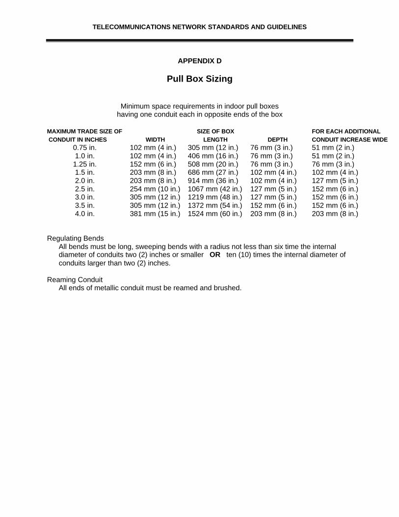
Pull boxes shall be placed in conduit runs which exceed 100 feet or in situationswhich require more than two 90 degree bends. Such pull boxes must be locatedso as to provide free and easy access, in straight sections of conduit only (pullboxes should never be used for a right angle bend), and must be installed toallow cable to pass through from one conduit to another in a direct line SeeAppendix D, of this section, for Pull box sizing.
All riser sleeves must be fire stopped and sealed following code andmanufacturers instructions.
2.2.5 Horizontal PathwaysThe horizontal pathways are facilities which support the installation andmaintenance of cables between the Telecommunication Closet and the stationoutlet locations. The City promotes the use of plenum-rated telecommunicationscable supported by a cable tray serving station conduit stubbed into the falseceiling space as the general distribution method.
2.2.6 Cable TrayThe cable tray will be NEMA Class Designation 12B (75 lbs per linear foot). TheCity has standardized on the use of Flextray cable trays. Trays can varybetween six (6) to twenty (20) inches in width, with a minimum depth of two (2)inches. Trays must qualify under NEC Section 318-7(b) as equipment groundingconductor. Smaller buildings and secondary tray sections serving fewer than 25stations may utilize a four (4) to eight (8) inch wide tray.

TELECOMMUNICATIONS NETWORK STANDARDS AND GUIDELINES
Trays are to be sized to accommodate both copper cable and fiber. The fiber willbe protected in interduct. There will be a minimum of two (2) one inch inter-ductsallowed per cable tray.
Trays should be secured on ten foot centers using a single center-mounted steelsupporting rod and bottom "T" connector or angled wall supports. If there will notbe access to both sides of the tray, or; other limitations will prohibit the placementof cable equally in both sides of the tray, a standard trapeze type support systemmay be used. Trays must meet seismic bracing standards #4.
The cable tray should be routed in a manner which will reduce the need for longunsupported cable runs. However, the tray need not be extended to cover allareas of a floor simply to transport cables to one or two locations. Cable installerscan utilize "J" hooks (on 6' centers) to support individual runs of cable, or a zonedconduit system can be used to supplement the cable tray.
Cable trays must only be utilized over areas with ceiling access and musttransition to a minimum of three (3) four-inch conduits when routed over fixedceiling spaces larger than 15 feet or containing any angle greater than 20degrees. Trays should be bonded end-to-end.
Trays should enter telecommunication closet six (6) inches into the room thenutilize a drop out to protect station cables from potential damage from the end ofthe tray. All penetrations through fire walls must be designed to allow cableinstallers to fire-seal around cables after they are installed. The use of tray-basedmechanical fire stop systems instead of changing to conduit is encouraged whena tray must penetrate a fire barrier.
Cable trays may not be placed closer than six (6) inches to any overhead lightfixture and no closer than twelve (12) inches to any electrical ballast. A minimumof eight (8) inches of clearance above the tray must be maintained at all times.All bends and T-joints in the tray must be fully accessible from above (within onefoot). Trays should be mounted no higher than twelve (12) feet above thefinished floor and must not extend more than eight (8) feet over a fixed ceilingarea.
A separate conduit sleeve (minimum of two inches) must be provided as apathway through any wall or over any obstruction (such as a rated hallway) fromthe cable tray into any room having a communications outlet. Such conduit runsmust be continuous over fixed ceiling areas, but may be sleeves between falseceiling spaces which have access.
2.2.7 Station OutletsThe "standard" wall outlet should be a 4 11/16 inch square (duplex) outlet boxserved by a ½-inch conduit (with no more than a total of 180 degrees of bend)covered with a duplex mud ring. Other specific station pathway configurationinformation is defined below:
TELECOMMUNICATIONS NETWORK STANDARDS AND GUIDELINES
• If flush mounted floor outlets are required, do not use poke-through outletsfed from the floor below. Instead, place a dual use (signal & power) presetoutlet in the floor surface and feed the conduit (1/2" for signal only) throughthe floor slab to the nearest wall and into the false ceiling. Flush mount unitsmust provide a space for telecommunications comparable to the standardquad NEMA outlet box.
• If a large number of such outlets are required, consider the use of a presetswith feeder duct (Walkerduct) served by multiple two-inch conduits directedinto the ceiling space.
• Custom counter or workstation installations requiring telecommunicationsservices, should be connected to a wall-mounted junction box fed by a one-half inch conduit. Conduit should be stubbed out at in the ceiling space.There should be two conduits, on opposing walls, servicing a workstation.See Appendix E, of this section, for labeling of station outlets.
• Station outlets should not be "daisy-chained" one to the other. However, ifabsolutely necessary, increase the feeder conduit size by a half-inch to thefirst outlet in line (two maximum).
• Station outlets shall; - accommodate a minimum of two 8 position / 8 conductor modular jacks - utilize compliant pin technology 110 style insulation displacement connectors
which allows the use of a 4 pair impact tool - allow for a minimum of 200 re-termination’s without signal degradation - utilize reactance balanced pair technology to address data circuit applicationsup to 100 MHz - provide universal application / multi-vendor supportive - support industry standards for T568A wiring options - have removable from the front with the faceplate mounted in place, andallows for the jack to pass through the faceplate without re-termination - have a hinged door option for areas having excessive air born contaminants - provide color coded snap in icons available for circuit identification - be constructed of high impact flame retardant thermoplastic - have available a gravity feed (45 degree angled) design - be available in screened version for 100 ohm ScTP cable- be UL Verified for TIA/EIA category 5 electrical performance
• The City has standardized on SIEMON’s Angled Category 5 CT Couplers thatare CAT 5 rated for outlets. The CT Couplers will be white in color for thevoice, blue in color for data, and orange for radio.
• Where indicated in the Project Specifics section, fiber outlets will be used.Specifics on these outlets are as follows:
- be available in ivory - flush mounted gravity feed (45 degree angled) design - accommodate a minimum of two SC or ST style adapters - universal application for both multi-mode and single mode connectors

TELECOMMUNICATIONS NETWORK STANDARDS AND GUIDELINES
- multi-vendor supportive - removable from the front with the faceplate left mounted in place - pass through design, so adapter can pass through the faceplate opening - provide a dust cover for unused ports - color coded snap-in icons available for circuit identification - made of high impact flame retardant thermoplastic- be made by an ISO 9001 and 9002 Certified Manufacturer
The City has standardized on SIEMON Company CT Series Fiber Couplers.
2.2.8 Faceplates All faceplates shall:
- be applicable to both fiber and copper applications - have write on designation labels for circuit identification with a clear plastic cover - be available in single gang, and double gang configurations - have the standard color of ivory - have optional modular furniture adapters available
- be made by an ISO 9001 and 9002 Certified manufacturer.
The City has standardized on SIEMON Company CT or MAX faceplates.
2.2.9 Surface Mount BoxesAll low profile surface mount boxes used for mounting surface mount informationoutlets shall:
- be available in 1, 2, 4, or 6 port versions - have built in cable management for both fiber and copper applications - be ivory in color - have at least three sides with breakouts and an opening in the base for cable or
raceway entry - provisions for an optional spring-loaded shutter door for added protection fromdust and other air born contaminants - have a designation area for printed or adhesive labels for circuit identification - have optional magnets which can be internally mounted - color coded snap in icons shall be available for circuit identification
- be made by an ISO 9001 or 9002 Certified Manufacturer.
The City has standardized on SEIMON Company SM Series Surface Mount Box.
TELECOMMUNICATIONS NETWORK STANDARDS AND GUIDELINES
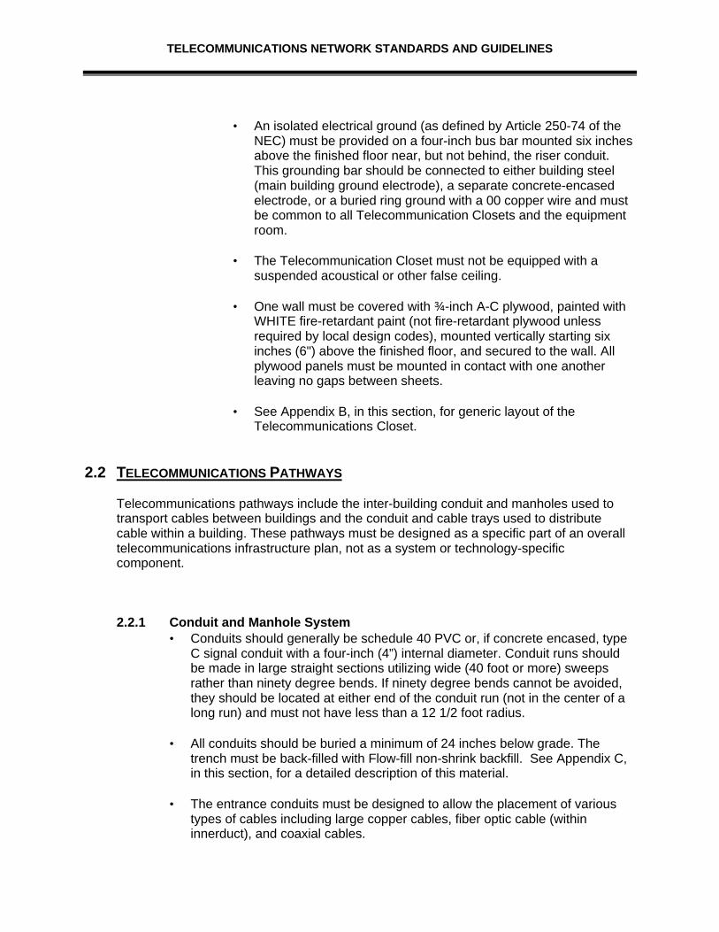
APPENDIX A
Service Entrance Room
Equipment Room
5'
7'
Data CommRack
Phone Backboard
Phone
Backboard
Phone Backboard
10'
15'
Data CommRack
Phone Backboard
Phone
Backboard
<--- This backboard should be used for voice terminations.

TELECOMMUNICATIONS NETWORK STANDARDS AND GUIDELINES
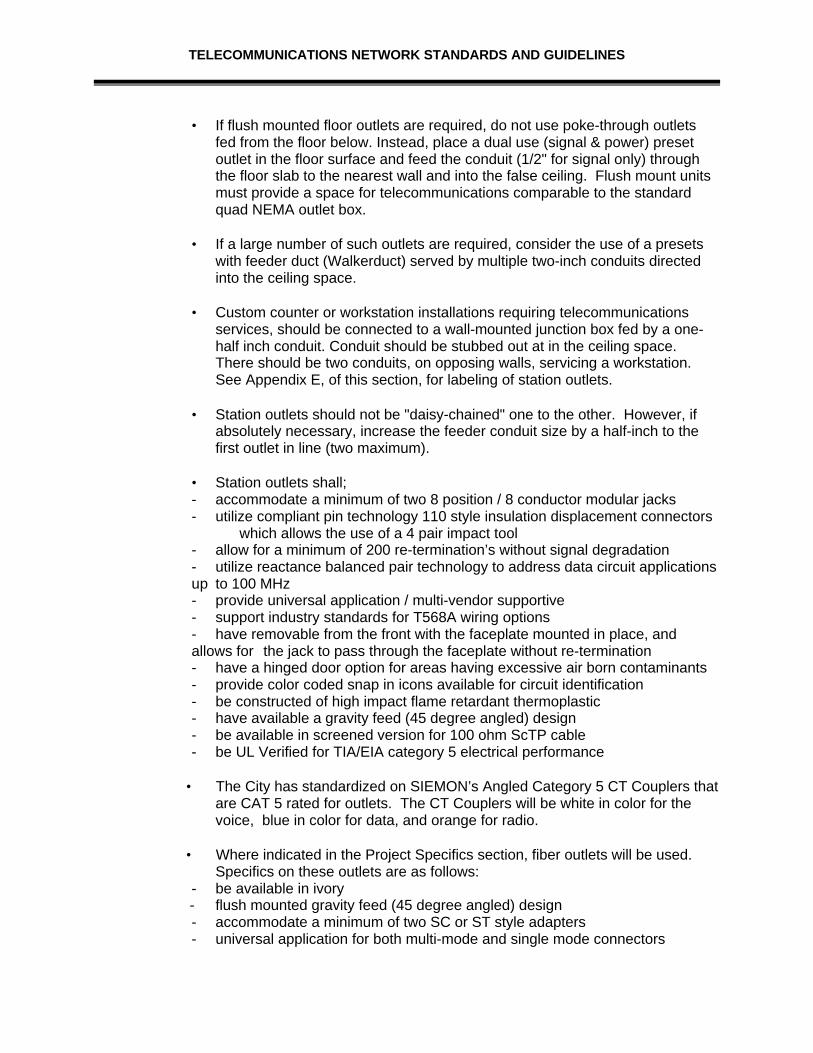
DRAWINGS ARE NOT TO SCALEAPPENDIX B
Telecommunications Closet
DRAWING NOT TO SCALE
5'
7'
Data CommRack
Phone Backboard
Phone
Backboard
<--- This backboard should be used for voice terminations.
TELECOMMUNICATIONS NETWORK STANDARDS AND GUIDELINES
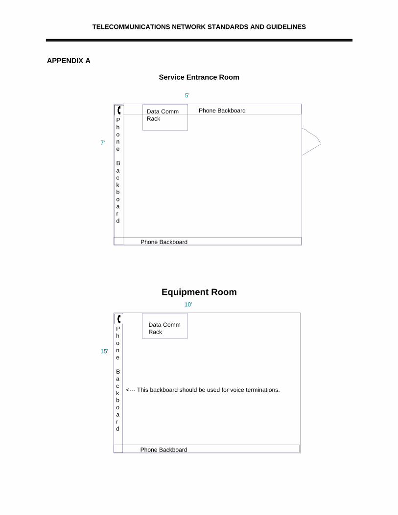
APPENDIX C
Flow-fill Non-shrink Backfill Specifications
MIX PERFORMANCE24 Hour Strength
8 psi Minimum12 psi Maximum
28 Day Strength60 psi Maximum
Maximum aggregate size = 1”
Cement - Type I-II Ideal (ASTM C 150)
SLUMP – at point of placement5” Minimum8” Maximum
Mix Proportions (per cubic yard of concrete)Absolute Volume
Cement – 0.45 sacks 42# 0.21 Cu. Ft.Water --- 39 gallons 325# 5.20 Cu. FtAir (Entrapped) --- 1.5% 0.41 Cu. Ft.1” Aggregate - ASTM C 33, Size No. 57 1700# 10.17 Cu. Ft.Sand --- ASTM C 33 1845# 11.24 Cu. Ft.
TOTAL 3912# 27.23 Cu. Ft.
Theoretical Unit Weight --- 143.7# / Cu. Ft. @ 1.5% airTheoretical Yield --- 27.23 Cu. Ft. @ 1.5% air% Sand of Total Aggregate --- 52%
NOTE: Aggregate Weights are based upon materials being in a saturated surface driedcondition.
TELECOMMUNICATIONS NETWORK STANDARDS AND GUIDELINES
APPENDIX D
Pull Box Sizing
Minimum space requirements in indoor pull boxeshaving one conduit each in opposite ends of the box
MAXIMUM TRADE SIZE OF SIZE OF BOX FOR EACH ADDITIONAL CONDUIT IN INCHES WIDTH LENGTH DEPTH CONDUIT INCREASE WIDETH
0.75 in. 102 mm (4 in.) 305 mm (12 in.) 76 mm (3 in.) 51 mm (2 in.)1.0 in. 102 mm (4 in.) 406 mm (16 in.) 76 mm (3 in.) 51 mm (2 in.)
1.25 in. 152 mm (6 in.) 508 mm (20 in.) 76 mm (3 in.) 76 mm (3 in.)1.5 in. 203 mm (8 in.) 686 mm (27 in.) 102 mm (4 in.) 102 mm (4 in.)2.0 in. 203 mm (8 in.) 914 mm (36 in.) 102 mm (4 in.) 127 mm (5 in.)2.5 in. 254 mm (10 in.) 1067 mm (42 in.) 127 mm (5 in.) 152 mm (6 in.)3.0 in. 305 mm (12 in.) 1219 mm (48 in.) 127 mm (5 in.) 152 mm (6 in.)3.5 in. 305 mm (12 in.) 1372 mm (54 in.) 152 mm (6 in.) 152 mm (6 in.)4.0 in. 381 mm (15 in.) 1524 mm (60 in.) 203 mm (8 in.) 203 mm (8 in.)
Regulating BendsAll bends must be long, sweeping bends with a radius not less than six time the internaldiameter of conduits two (2) inches or smaller OR ten (10) times the internal diameter ofconduits larger than two (2) inches.
Reaming ConduitAll ends of metallic conduit must be reamed and brushed.

TELECOMMUNICATIONS NETWORK STANDARDS AND GUIDELINES
APPENDIX E
Station Outlet Labeling
Cable, Equipment Room, Telecommunication Closet
Equipment Room and Telecommunication Closet labeling will begin on the first floor andcontinue to other floors if necessary. They will be identified by an Alpha Character starting with:A
ROOM labeling will start with 100 and continue upwards. If possible the 200 number series willstart on the second floor, the 300 number series in the third floor and etc. This would change to1000 number series if there is more than 100 rooms per floor.
FACE PLATE labeling will start with A and C if it is a duplex plate, with A being the white voicejack and C being the black data jack, continued in the following fashion:
A B E F I J M N Q R U V Y C D G H K L O P S T W X Z
AA BB EE FF II JJ MM NNCC DD GG HH KK LL OO PP
QQ RR UU VV YYSS TT WW XX ZZ
A typical faceplate numbering series would be as follows for a single drop:
A100A for VoiceA100C for Data
A typical faceplate numbering series would be as follows for a Quad drop:
A100A & A100B for VoiceA100C & A100D for Data
For Telecommunication Closet cabling use the following format:
A1B for a cable running from Equipment Room A to Telecommunication Closet B at EquipmentRoom A location.
B1A for a the same cable running from Equipment Room A to Telecommunication Closet B atTelecommunication Closet B location.

TELECOMMUNICATIONS NETWORK STANDARDS AND GUIDELINES
SECTION III: WIRE, CABLE & SUPPORT SYSTEMS
3.0 WIRE, CABLE, AND SUPPORT SYSTEMS
Although many of the existing City Buildings have used differing design guidelines for thetelecommunications cable installed to support their systems, this section identifies asuggested approach centered around developing industry standards for voice and datacommunications. The use of manufacturers brand names does not indicate these are theonly providers of a particular component.
The components in this section are divided into three major groups. The first is the coppercable and associated hardware used to install and terminate this media. The second isfiber optic products, and the third is coaxial cable products. While some explanation isprovided regarding system usage, this section is not intended to identify all of the potentialuses of a given product.
It must be understood that these guidelines are based upon local needs and standardsregarding the utilization of telecommunications media.
3.1 COPPER CABLE SYSTEMS
Copper cable systems have been in use in all City buildings for a variety of purposes formany years. Recent changes in the industry, however, have given new life to this mediumas a means to meet higher performance telecommunications needs. The adoption of theEIA/TIA-568A standards identifies minimum performance characteristics for a standardapproach to station wire utilizing unshielded twisted station cable.
This standard defines several characteristics for copper backbone (inter-building and riser)cable and station cables. Subsequent technical bulletins have also been issued defininghigher performance alternative specifications for station cable and connecting hardware.
The product vendors have reacted to these recent bulletins by providing a variety of newcable types aimed at filling the requirement for high speed station cable connections. Inaddition to cable, several new terminal blocks and station jacks have been introducedwhich are designed to assist with the provision of higher data rates. As with any highperformance product, the new types of cable must be installed using components andtechniques which will provide and maintain a high quality environment.
Copper cable is classified by many parameters including size (gauge), performancecharacteristics, type of conductor, and cable composition. All of the type of cable utilizedas part of these guidelines is solid wire rather than stranded. The gauge is generally 24American Wire Gauge (AWG) however, in some cases 22 AWG (a larger size cable) isrequired to meet distance-sensitive performance parameters.
The composition of the cable will be discussed later in this section as it relates to thevarious types of cables (inter-building, riser, station). Performance characteristics also vary

TELECOMMUNICATIONS NETWORK STANDARDS AND GUIDELINES
by type and usage of cable and include a wide variety of electrical and mechanicalaspects. There are three measurements which are frequently used to "grade" a coppertelecommunications cable. These measurements are:
• Nominal mutual capacitance is the measurement of the effects of electrostatic chargeson adjacent surfaces (cable pairs) and is measured in farads or picofarads (trillionth ofa farad). Within specific parameters a lower number can provide better performance.
• Attenuation is a measurement of the loss of signal over a cable pathway. It ismeasured in decibels (-dB) and the lower the number the better performance offeredby the cable.
• Cross-talk (Near-End Cross talk - NExT) is the level of signal which passes from onecable pair to another within a single cable sheath. It is also measured in -dB's.However, the higher the number the better.
These descriptions are offered not as the only, or even as the best, means of analyzingperformance specifications, but they are important components in determining what cablesshould be used in a particular situation.
3.1.1 Station CableStation cable, the cable connecting the users jack to the terminal blocks in theTelecommunication Closet, has undergone significant changes in the last fewyears. Several vendors started offering cables with improved performancecharacteristics and classified such cable as "data grade" or "LAN" cable.
The industry responded to this need for different cable performance levels byadopting the EIA/TIA 568A (plus TSB-67) cable specifications which identifiesfive performance categories for unshielded twisted copper cables. In general,the first two categories of cable are not recognized as part of the standard andare classified only for voice and low speed data applications. The third and fourthcategories are no longer used within the City. The fifth category is:
• Category 5: This highest level cable is intended for applications up to 100Mb/sec (such as FDDI).
It is important to note that simply installing a Category 5 cable will not provide theuser with a 100 Mb/sec pathway. All of the hardware components which make upthe wire pathway, such as the terminal blocks, patch cords/jumper wires, userjack, and line cord, must also meet Category 5 specifications and should bedesigned to work together. In addition, installation techniques used to implementa Category 5 pathway contain very strict guidelines regarding cable terminations,routing, and layouts in order to maintain performance specifications.
The City "standard" Category 5 wire configuration consists of two (2) four-pairunshielded copper pairs (UTP) / Screened twisted pair (ScTP) cables; one forvoice and one for data. This standard has been adopted based on historicalusage within the City and the extensive support available within the industry.The City’s standard is to use Belden’s DataTwist 350. This standard has been

TELECOMMUNICATIONS NETWORK STANDARDS AND GUIDELINES
adopted based on historical usage within the City, the support available withinthe industry, the stable performance across the frequency range, and thecapabilities to meet our future networking needs.
The "standard" station outlet will consist of two (2) four-pair DataTwist 350 cablesterminated in two (2) modular 8 position jacks. The cable types are definedbelow:
• Voice station four-pair - shall be Category 5, four-pair, (24 AWG, CMP rated)as defined in the ANSI/EIA/TIA 568A standard.
• Data station four-pair (high speed) - shall be Category 5, four-pair, (24 AWG,CMP rated) as defined in the EIA/TIA 568A.
• All Category 5 installations must also conform to the componentconfigurations and installation practices contained in EIA/TIA 568A.
• Cable, at the station end, should have a minimum of a foot of extra cable forease of service in the future. The slack should be looped and left in the box.
The use of plenum rated cable is required in all situations; does not matterwhether the cable is being placed within a ceiling space used as an air plenum.
3.1.2 Station JacksThe jack or outlet which terminates the station cable at the users locationbecomes an integral part of the distribution system if a true Category 5 cablesystem is to be installed. It must terminate the cable with an electrically soundconnection and should provide some flexibility in allowing for the connection ofvarious communication devices.
The City standard is for the termination of the two four-pair station cables in twoseparate 8 position modular jacks. See Appendix A, in this section, for details onhow station jacks are to be terminated. See Section 2 for specifics on Stationoutlets, Faceplates, and Surface Mount Boxes.
Each telecommunication closet will be connected to the building's equipment/entrance room riser with cables sized to provide a pair count of four-pair to eachstation served.
3.1.3 Riser CableIt is important to use UTP Category 5 grounded shielded cable in the buildingrisers to lessen the impact of interference. Using a shielded but ungroundedcable actually increases the potential for electrical interference in the cable. Risercables should be grounded at the point of origination and at any floor in whichpairs leave the cable sheath. If the ground is not adequate for use as a shieldground, it must be reworked or replaced to provide the proper connection. SeeSection 2 for grounding specifications.

TELECOMMUNICATIONS NETWORK STANDARDS AND GUIDELINES
All riser cables shall be CMR rated, bonded, shielded, air-core, 24 gauge, withstaggered twists and a mutual capacitance of not more than 19 nF per 1000 feet.All riser cables must be of a type compliant with the specifications of EIA/TIA568A
3.1.4 Inter-building CableInter-building cable is available in a variety of different configurations, sizes, andperformance specifications. Normally the cable will be 24 gauge with a standardcapacitance of 83 to 87 nanofarads per mile and a staggered twist design. Fordistance beyond 2,500 feet, consider the use of 22 gauge cable to improveperformance levels for many PBX electronic instruments.
Cable placed in a conduit should have a stalpeth or alpeth sheath and must havea water-exclusion gel filling to limit the introduction of moisture into the cable.This type of "gel-fill" or "icky-pik" cable cannot be brought directly into a buildingand terminated without first being enclosed in conduit and terminated into anenclosed splice. Do not terminate filled cables directly onto protector or terminalblocks.
If steam or high temperature is a potential problem, cable specially made withadditional mechanical protection should be installed for such environments.
Any cable pulled through a long or difficult conduit path, should be equipped witha bonded sheath.
3.1.5 Cable RoutingAll horizontal cables regardless of media type shall not exceed 90 m (295 ft) fromthe telecommunications outlet in the work area to the horizontal cross connect.The combined length of jumpers, or patch cords, and equipment cables in thetelecommunications closet and the work area should not exceed 10m (33 ft).
Two horizontal cables shall be routed to each work area. The horizontal cablesshall be: connected to a station outlet (jack), four pair unshielded twisted pair(UTP) / Screened twisted pair (ScTP).
Horizontal pathways shall be installed or selected in such that the minimum bendradius of horizontal cables is kept within manufacturer specifications both duringand after installation.
In open ceiling cabling, cable supports shall be provided by means that arestructurally independent of the suspended ceiling, its framework, or supports.These supports shall be spaced no more than 1.5 m (5 ft) apart.
Telecommunications pathways, spaces and metallic cables which run parallelwith electric power or lighting shall be installed with a minimum clearance of50mm (2 in).
For voice or data applications, 4-pair UTP or fiber optic cables shall be run usinga star topology from the telecommunications closet on each floor to every

TELECOMMUNICATIONS NETWORK STANDARDS AND GUIDELINES
individual information outlet. All cable routes shall be approved by the City priorto installation of the cabling.
The Contractor shall observe the bending radius and pulling strengthrequirements of the 4-pair UTP/ScTP and fiber optic cable during handling andinstallation.
Each run of the UTP/ScTP cable between horizontal portion of the cross-connectin the telecommunication closet and the station outlet shall not contain splices.
In the telecommunications closet where cable trays or cable racking are used,the contractor shall bundle together the horizontal cable with reusable colorcoded hook and loop cable managers (velcro tie wraps) to create a neatappearing and practical installation. SIEMON Company VCM Seriesrecommended. Tie wraps shall be used at appropriate intervals to secure cableand to provide strain relief at termination points. These wraps shall not be overtightened to the point of deforming or crimping the cable sheath.
Hook and loop cable managers shall be used in the closet where reconfigurationof cables and terminations may be frequent.
The Contractor will use station conduit, to be a minimum of one-half inch, and isto be stubbed into the ceiling space.
In a false ceiling environment a minimum of three (3) inches (75mm) shall beobserved between the cable supports and the false ceiling.
Continuous conduit runs installed by the contractor should not exceed 100 feet orcontain more than two (2) 90 degree bends without utilizing appropriately sizedpull boxes.
3.1.6 Cable Termination3.1.6.1 Blocks
In most cases the recommended cable termination blocks, also calledterminals, terminal blocks, and punch down blocks, are SEIMON CAT5 S66M-50 blocks, M Series.
All block assemblies should include sufficient 188B2 jumperbackboards or similar devices mounted adjacent to the 66 blocks foreffective use as cross-connect wire holders. The proper size retainingclips must be used for all cable termination's.
Labeling for the blocks, both room and color indicators, will behandled as outlined in Section 2.
3.1.6.2 Modular Patch PanelThe termination panels shall support the appropriate Category 5applications and facilitate cross-connection and inter-connection usingmodular patch cords. The panels shall be sized to fit an EIQ standard

TELECOMMUNICATIONS NETWORK STANDARDS AND GUIDELINES
19 inch relay rack or be capable of mounting to a wall. Modular PatchPanels will be used for data terminations.
The panel shall:• be made of black anodized aluminum in 16, 24, 28, 32, 48, 64 and
96 port configurations• accommodate at least 24 ports for each rack mountable space• have Cat 5 outlets (jacks) available in T568A. See Section 2 for
specifics on outlet types to be used• allow for a minimum of 200 re-terminations without signal
degradation• have modular ports compliant with FCC CFR 47 part 68 subpart F
and IEC 603.7 with 50 microinch gold plated contacts• allow for the use of a 5 pair 110 style impact termination tool• have cable tie eyelets and a rear cable management bar• be fully enclosed front and rear for physical protection of printed
circuit board• have port identification numbers provided on both the front and
rear of the panel• have an optional adhesive circuit identification and color coding
designation strips provided with the panel• have self adhesive clear label holders, and white designation
labels shall be provided with the panel with optional color labelsavailable to the City
• be available in a 24 port ScTP veision which exceeds the transferimpedance requirements of ISO/IEC 11801. This panel mustaccept two types of cable preparation for termination
• be consistent with the electrical specifications outlined within thisdocument
• be UL Verified for TIA/EIA category 5 electrical performance• accept 100 style patch plugs as a means of termination• be made by an ISO 9001 and 9002 Certified Manufacturer.SIEMON HD5 Series Patch Panels Recommended.
3.1.7 Cable ProtectionCable protectors are used in conjunction with proper bonding and grounding toprovide electrical hazard protection to staff and sensitive electronic equipment.The decision of where and how to use protectors is not clear cut and must beviewed as part of an overall cable design process. Generally, copper cablesserving a voice switching system should be protected. The station end (otherbuildings) protection requirements are based on the individual layout, potentialfor lighting strikes or power faults, and historical electrical fault problems.
The Main Distribution Frame (MDF) should be served by wall or rack mountedprotectors designed to be connected to the terminals. For large installations, it isoften better to use a protector panel which is separate from the cross-connectfield to allow testing of cables and a separation within the work area.

TELECOMMUNICATIONS NETWORK STANDARDS AND GUIDELINES
In individual buildings and in smaller installations, the recommended protectorpanels utilize an integrated termination and protector panel unit whichincorporates the terminal blocks with the protector panel housing. Protectormodules shall be fast acting, 3 element, (5 pin) gas-tube units with sneak current(low voltages) protection. Brand of lightening protectors that can be used, areAT&T 188ENA1.
3.1.8 Splice CasesAll splices must be contained within a splice case. All outdoor (vault and tunnel)splice cases should be encapsulated, re-enterable units fully dressed andenclosed to fit the number and type of cables terminated. All end plates must bedesigned for the number and size of cables served by the splice case and bedesigned to seal around each cable individually.
Splice cases are designed for specific environments such as for use in vaults,buried underground, for use within a building, or mounted on a pole. Thedesigner must select and specify an appropriate unit when installing copper cablesystems. Poor products, inadequate installation techniques, or incorrect use of aparticular product can lead to moisture leaks and ultimately cable troubles.
Outdoor vault and tunnel splice cases should be heavy duty stainless steel.Indoor cases used to terminate inter-building cable filled with water-exclusion gelshould also be capable of completely sealing around all cables at each end of thecase.
Cable shields must be bonded through all splices.
3.2 FIBER OPTIC CABLE SYSTEMS
Fiber optic cable is used to support voice, data, and video systems in a wide range ofinstallations. An increasing number of manufacturers, improvements in splicing methods,developing standards, and reduced cost electronics have all helped push this medium intothe forefront of telecommunications services. A prime point to remember, however, is thatany fiber-based product needs an interface and electronic components to make themactive. This means that in several instances copper cable is still a good choice for basictelecommunications services, and in some cases, the only practical choice.
The cost tradeoffs of fiber versus copper cable installations are very complex and due tothe nature of the industry, are in a constant mode of change. Unless otherwise indicatedin the Project Specifics of this document, the City is not wanting to install fiber to the desktop. However, the City does want to have the inter-duct in place, for when the need hasarrived for this type of technology, fiber can be easily installed. Thus the reason forinstalling inter-duct on the cable trays outlined in Section 2.
This document will focus on the types of fiber cable and support equipment required ratherthan the specific applications to which fiber may be used.
3.2.1 Station Cable

TELECOMMUNICATIONS NETWORK STANDARDS AND GUIDELINES
The inter-building station fiber should be a multi-mode, 62.5/125 um, dual (twooptics) cable, plenum-rated (OFNP), with a dielectric strength member and/or areinforced yarn covering for physical protection. These cables should beterminated in "ST" connectors mounted in the users station outlet and capped ifnot immediately used. The performance of this fiber must comply with the FiberData Distributed Interface (FDDI) specifications. Each pair of fibers shouldterminate in a fiber patch panel (rack mounted for more than 24 stations) in theTelecommunication Closet.
3.2.2 Fiber Riser CableMulti-mode fiber optic cable should be installed in all building telecommunications(riser) rooms to support today's data communications needs. At a minimum, thefiber riser cables should consist of twelve (12) fibers to each TelecommunicationCloset from a master panel in the building's equipment room. These cablesshould be "home-run" cables directly from the equipment room into the individualTelecommunication Closets. All fiber cables should be contained within aninnerduct and be clearly marked as optical cables for additional physicalprotection. All fiber riser cables must be OFNR rated, multi-mode, 62.5/125 um,tight buffered, fan out cables with a dielectric central member and must carry acrush resistance rating of at least 1100 lbs/in. Cables must have a 900 um bufferand must meet the following performance characteristics:
• Maximum attenuation: 3.5 dB/km @ 850 nm; 1.5 dB/km @ 1300nm
• Minimum bandwidth: 160 MHz/km @ 850; 500 MHz/km @ 1300nm
3.2.3 Inter-building Fiber CableThis building will be connected to the City’s main telecommunications distributionpoint with both multi-mode and single mode optical fibers.
This building should contain an additional 20 foot loop of fiber cable which isneatly coiled and secured before reaching the final termination point which canbe utilized as splicing slack in the event of a cable break. The cable should beinstalled within an orange, one-inch interduct in a tunnel or conduit and withineach building. Four (4) one-inch interducts should be placed in one four-inchconduit feeding to every building for use by the fiber optic cable. The inter-building cables must be water- exclusion gel-filled, dielectric, loose tubeconstruction with a tensile strength of 600 lbs (long term) and designed forinstallation in underground ducts. Fiber optic cable should be pulled throughconduct using a swivel and special fiber cable grip.
All gel-filled cable should either be terminated into a splice case or have the endsof the cable dressed with a blocking kit to eliminate the seepage of the gel.
The cables should meet or exceed ANSI/EIA/TIA-492 AAAA specifications andshould have the following characteristics:
Multi-Mode Optics

TELECOMMUNICATIONS NETWORK STANDARDS AND GUIDELINES
• 62.5/125 um (core/cladding) dual window (850 and 1300 nanometers)• Maximum attenuation: 3.5 dB/km @ 850 nm and 1.75 dB/km @ 1300 nm• Minimum bandwidth: 160 MHz/km @ 850 and 500 MHz/km @ 1300 nm• .275 numerical aperture• Minimum pulling tension of 600 lbs.
3.2.4 Fiber Optic Patch PanelsAll fiber optic cables should be terminated on ceramic ST connectors (withcompatible bulkheads) in individual patch panels. In each TelecommunicationCloset these panels should generally be pre-loaded, wall-mount units equippedwith a lockable cover. These units will terminate the riser fiber optics and providea pathway for interconnecting to fiber-based electronics. The fiber optic patchpanel connections should provide .4 dB or less insertion loss. However, if fiberoptic station cables are to be installed, consideration should be given to installinga frame-mount patch panel equipped to terminate 24 or more optics.
In each building's equipment room, there should be installed a wall- or frame-mounted fiber patch panel equipped to terminate the incoming inter-building fiberand the riser cables. Patch cords (pre-made), should be provided, to interconnectone pair of fibers from each Telecommunications Closet to the inter-building fibercable. The patch cords (jumpers) should be impact-resistant double-fiber cablesof the same performance characteristics as the multi-mode fiber. These fiberoptic patch panel connections should provide .4 dB or less insertion loss.
The City’s Service Entrance Room should be equipped with a frame mountedfiber optic patch panel which will terminate all inter-building fiber cables and anyriser cables which serve that building. At a minimum, this unit must be fullyequipped (pre-loaded) to terminate 24 optics. The frame should be equippedwith a jumper tray.
As the City has standardized on SEIMON products for all of it’s copper cableterminations, it is recommended that the Contractor continue with that standardin the fiber optic arena.
3.2.5 Fiber Optic Interconnect Centers, Panels and TraysAll interconnect centers, panels and trays (units) shall provide cross-connect,inter-connect, splicing, capabilities and contain cable management for supportingand routing the fiber cables/jumpers.
3.2.5.1 Wall MountThe wall mount interconnect center shall:
• have a low profile compact design, able to accommodate up to 12, 24and 48 port configurations
• be modular in design with management clips that provide twoindependent levels of slack storage to comply with fiber bend radiusand the recommended slack storage length
• have a door which is hinged and lockable• have an administrative labeling system, and must be available on a
hinged door, capable of locking for protection
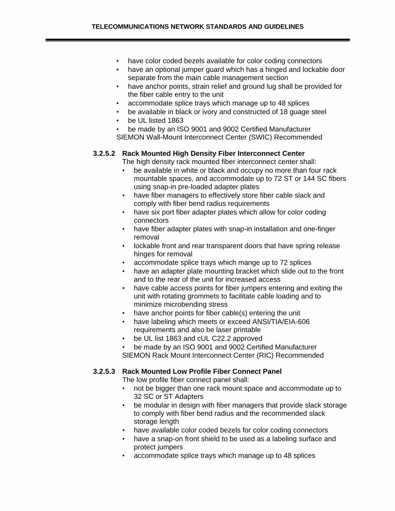
TELECOMMUNICATIONS NETWORK STANDARDS AND GUIDELINES
• have color coded bezels available for color coding connectors• have an optional jumper guard which has a hinged and lockable door
separate from the main cable management section• have anchor points, strain relief and ground lug shall be provided for
the fiber cable entry to the unit• accommodate splice trays which manage up to 48 splices• be available in black or ivory and constructed of 18 guage steel• be UL listed 1863• be made by an ISO 9001 and 9002 Certified ManufacturerSIEMON Wall-Mount Interconnect Center (SWIC) Recommended
3.2.5.2 Rack Mounted High Density Fiber Interconnect CenterThe high density rack mounted fiber interconnect center shall:• be available in white or black and occupy no more than four rack
mountable spaces, and accommodate up to 72 ST or 144 SC fibersusing snap-in pre-loaded adapter plates
• have fiber managers to effectively store fiber cable slack andcomply with fiber bend radius requirements
• have six port fiber adapter plates which allow for color codingconnectors
• have fiber adapter plates with snap-in installation and one-fingerremoval
• lockable front and rear transparent doors that have spring releasehinges for removal
• accommodate splice trays which mange up to 72 splices• have an adapter plate mounting bracket which slide out to the front
and to the rear of the unit for increased access• have cable access points for fiber jumpers entering and exiting the
unit with rotating grommets to facilitate cable loading and tominimize microbending stress
• have anchor points for fiber cable(s) entering the unit• have labeling which meets or exceed ANSI/TIA/EIA-606
requirements and also be laser printable• be UL list 1863 and cUL C22.2 approved• be made by an ISO 9001 and 9002 Certified ManufacturerSIEMON Rack Mount Interconnect Center (RIC) Recommended
3.2.5.3 Rack Mounted Low Profile Fiber Connect PanelThe low profile fiber connect panel shall:• not be bigger than one rack mount space and accommodate up to
32 SC or ST Adapters• be modular in design with fiber managers that provide slack storage
to comply with fiber bend radius and the recommended slackstorage length
• have available color coded bezels for color coding connectors• have a snap-on front shield to be used as a labeling surface and
protect jumpers• accommodate splice trays which manage up to 48 splices

TELECOMMUNICATIONS NETWORK STANDARDS AND GUIDELINES
• be available with a drawer mechanism which slides from the front ofthe rack and has defeatable latches to allow removal
• have quarter turn fasteners to lock it closed and a smokepolycarbonate cover for protection
• have anchor points, helical wrap and ground lug for the fiber cableentering the unit
• by made by an ISO 9001 and 9002 Certified ManufacturerSIEMON Fiber Connect Panel Recommended
3.2.5.4 Rack Mounted Fiber TrayThe rack mounted fiber tray shall:• be made of 18 guage steel with a black finish• available in 16, 24, 48, 32, and 48 port configurations and be able to
double that port count utilizing 4 port adapters• accommodate both SC and ST adapters• have changeable ports which are removed fromthe front of the unit
to allow custom configuration or modification• have silk screened port identification numbers provided on both the
front and rear of the unit• have ANSI/EIA-310 compatible mounting slots• include fiber managers that manage slack storage so as to comply
with fiber bend radius requirements and slack storage lengthrecommendations
• accommodate splice trays which manage up to 48 splices• have a cover with quarter turn screws for easy access• not exceed a 10” depth for mounting in standard cabinets and
enclosures• be provided with strain relief lugs for fiber entering the unit from the
side of back• be made by an ISO 9001 and 9002 Certified ManufacturerSEIMON CT Fiber Management Tray Recommended
3.3 CROSS CONNECT WIRE AND PATCH CORDS3.3.1 Cross Connect Wire
The cross-connect wire shall:• have pair condutors bonded together to maintain pair twist• be available in 1, 2, 3, and 4 pair reels of 1000 feet• be color coded• be made by an ISO 9001 and 9002 Certified Manufacturer• exceed ANSI/TIA/EIA 568-A and ISO/IEC 11801 specifications for category 5SIEMON Category 5 Cross-connect Wire Recommended
3.3.2 Patch CordsWhere applicable the contractor shall supply patch cords(factory assembled Plug-ended jumpers) for patch panel andterminal blocks.

TELECOMMUNICATIONS NETWORK STANDARDS AND GUIDELINES
3.3.2.1 Modular Patch Cords: Category 5Category 5 modular patch/equipment cords shall:• be round, and consist of eight insulated 24 AWG, stranded copper
conductors, arranged in four color coded twisted pairs within a flameretardant jacket
• be equipped with modular 8 position (RJ45style) plugs on both endswired straight-through with standards compliant wiring
• modular plugs exceed FCC CFR 47 part 68 subpart F and IEC 603-7 specifications, and have 50 microinches of gold plating over nickelcontacts
• modular cords should include a molded strain relief boot• ScTP cords, shield continuity shall bemaintained through the
modular plug shield and not via the contacts• be available in any custom length and standard lengths of 3, 5, 7 ,
10, 15, 20 and 25 feet.• be made by an ISO 9001 and 9002 Certified ManufacturerSIEMON COMPANY MC5 Series Modular Cords Recommended
3.3.2.2. 110 Patch Cords: Category 5110 patch cords shall:• be factory or field assembled using category 5 compliant 110 patch
plugs and stranded category 5 cable• have plugs available in 1, 2, 3, and 4 pair sizes• be available in factory made standard lengths of 3, 5, 7, 10, 15, 20,
and 25 feet and any custom length• be made by an ISO 9001 and 9002 Certified ManufacturerSIEMON Company S110P Series Plugs and Cords Recommended
3.3.2.3 Modular patch Cords: Category 5The 110 to modular patch cords shall:• be factory or field assembled using category 5 compliant 110 patch
plugs and stranded category 5 cable• be available in 2 and 4 pair sizes with eight position modular plugs• be made from factory assembled modular cords for field assembly
or performance is not guaranteed• have modular plugs which exceed FCC CFR 47 part 68 subpart F
and IEC 603-7 specifications, and have 50 micro-inches of goldplating over nickel contacts
• be available in factory made cords of any custom length andstandard lengths of 3, 5, 7, 10, 15, 20 and 25 feet
• have available colored boots at the base of the modular connectorand snap in icons on the 110 connector for administrative purposes
• be made by an ISO 9001 and 9002 Certified ManufacturerSIEMON S110P to Modular Patch Cords Recommended
3.3.2.4 Fiber Patch Cords (Jumpers)Fiber equipment cords shall:

TELECOMMUNICATIONS NETWORK STANDARDS AND GUIDELINES
• be available in standard lengths of 1, 3, and 5 meters, customlengths shall also be available, and shall meet or exceed standardsas defined in ANSI/TIA/EIA-568-A and ISO/IEC 11801
• utilize simplex or duplex fiber cable that is 62.5/125 micronmultimode, OFNR riser grade, and meets the requirements of UL1666
• attenuation shall not exceed 3.5 dB/km @ 850 nm wavelength or1.0 dB/km @ 1330 nm
• cable jacket color shall be orange. The connects shall be SC or STin accordance with TIA/EIA-568-A and must include a ceramicferrule
• ST connectors must have a metal coupling nut• terminated connects shall exhibit a maximum insertion loss of 0.75
dB with an average of 0.50dB when tested at either 850 nm or 1300nm wavelengths
• be made by an ISO 9001 and 9002 Certified Manufacturer• be UL 1666 approvedSIEMON Company FJ Series Fiber Jumpers Recommended
3.4 COAXIAL CABLE SYSTEMS
Prior to the vendor installing a Cable TV system, vendor should meet with the City’s CableProduction Director to develop a design that is compatible with theCity’s needs.
Although not utilized as much as it was only a few years ago, coaxial cable still plays animportant role in the distribution of multi-channel video programming within and betweenbuildings. Other forms of coaxial cable are used for special purposes such as connectingparticular data vendor products and as Ethernet baseband cables (thick and thin cable.)For purposes of this document we are assuming the "standard" coaxial cable configurationis the distribution of multi-channel video signals.
There are a variety of cost effective, high quality, multiple channel fiber optic based videodistribution systems on the market today. Most of these, however, are targeted as analternative to major video feeder trunks and are designed to bring several channels into abuilding. This type of configuration can be very cost effective if fiber cable is alreadyavailable or will be installed regardless of the need for video distribution. This alternativeshould be explored before expanding a broadband inter-building coaxial cable system. Allcoaxial cable will be plenum rated regardless of where it’s located.
Multi-channel video distribution within a building, however, is still most economical withcoaxial cable. It is generally easy to work with, is available from a variety of sources, andcan be installed without extensive training. Television monitors can be directly connectedto the cable and can access multiple channels without the need to purchase separateconverters. The components necessary to drive the system are relatively inexpensive andeasy to install.
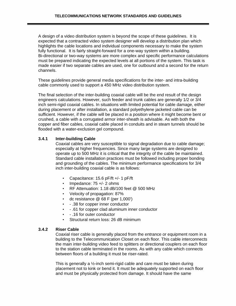
TELECOMMUNICATIONS NETWORK STANDARDS AND GUIDELINES
A design of a video distribution system is beyond the scope of these guidelines. It isexpected that a contracted video system designer will develop a distribution plan whichhighlights the cable locations and individual components necessary to make the systemfully functional. It is fairly straight-forward for a one-way system within a building.Bi-directional or two-way systems are more complex and specific performance calculationsmust be prepared indicating the expected levels at all portions of the system. This task ismade easier if two separate cables are used, one for outbound and a second for the returnchannels.
These guidelines provide general media specifications for the inter- and intra-buildingcable commonly used to support a 450 MHz video distribution system.
The final selection of the inter-building coaxial cable will be the end result of the designengineers calculations. However, such feeder and trunk cables are generally 1/2 or 3/4inch semi-rigid coaxial cables. In situations with limited potential for cable damage, eitherduring placement or after installation, a standard polyethylene jacketed cable can besufficient. However, if the cable will be placed in a position where it might become bent orcrushed, a cable with a corrugated armor inter-sheath is advisable. As with both thecopper and fiber cables, coaxial cable placed in conduits and in steam tunnels should beflooded with a water-exclusion gel compound.
3.4.1 Inter-building CableCoaxial cables are very susceptible to signal degradation due to cable damage;especially at higher frequencies. Since many large systems are designed tooperate up to 500 MHz it is critical that the integrity of the cable be maintained.Standard cable installation practices must be followed including proper bondingand grounding of the cables. The minimum performance specifications for 3/4inch inter-building coaxial cable is as follows:
• Capacitance: 15.6 pF/ft +/- 1 pF/ft• Impedance: 75 +/- 2 ohms• RF Attenuation: 1.18 dB/100 feet @ 500 MHz• Velocity of propagation: 87%• dc resistance @ 68 F (per 1,000')• - .38 for copper inner conductor• - .61 for copper clad aluminum inner conductor• - .16 for outer conductor• Structural return loss: 26 dB minimum
3.4.2 Riser CableCoaxial riser cable is generally placed from the entrance or equipment room in abuilding to the Telecommunication Closet on each floor. This cable interconnectsthe main inter-building video feed to splitters or directional couplers on each floorto the station cable terminated in the rooms. As with any cable which connectsbetween floors of a building it must be riser-rated.
This is generally a ½-inch semi-rigid cable and care must be taken duringplacement not to kink or bend it. It must be adequately supported on each floorand must be physically protected from damage. It should have the same

TELECOMMUNICATIONS NETWORK STANDARDS AND GUIDELINES
capacitance and impedance measurements as the inter-building cable, howeverthe attenuation (loss) will be greater. The specific performance measurementsshould be as defined below:
• Capacitance: 15.6 pF/ft +/- 1 pF/ft• Impedance: 75 +/- 2 ohms• RF Attenuation: 1.65 dB/100 feet @ 500 MHz• Velocity of propagation: 87%• dc resistance @ 68 F (per 1,000')• - .86 for copper inner conductor• - 1.34 for copper clad aluminum inner
Conductor• - .39 for outer conductor• Structural return loss: 26 dB minimum
3.4.3 Station CableCoaxial station cable can be distributed in several methods. One way is to loopthe cable into and out of each outlet location calculating the expected loss ateach point until you reach a 3 dBmV signal level. Another is to bring a feedercable down a central passageway (such as a cable tray) and connect multipleport taps and distribute individual station cables to each outlet.
The third is to home run each cable between the Telecommunication Closet andeach outlet. This method is very straight forward if the system is expected toserve a two-way role of both transmitting and receiving video signals. If thismethod is utilized, it is often advisable to install a fixed length of cable to eachoutlet thereby fixing a standard signal value from any tap in the system. A similarresult can be achieved through the use of pads and attenuators.
The recommended methods are the latter two; using a feeder cable andindividual station cables, and installing individual home run cables. The finaldetermination will be the responsibility of the system designer and will be basedupon known and expected utilization of the system.
Any cable installed must be plenum-rated. These cables should be RG-6 coaxialcables with a bonded foil aluminum braid foam polyethylene dielectric and a .04"copper clad steel center conductor. The cables should be rated for use up to 600MHz and tested up to 500 MHz. "F" connectors with a matching smaller (thanfor PVC) diameter crimp sleeve must be used.
TELECOMMUNICATIONS NETWORK STANDARDS AND GUIDELINES
SECTION IV: PLANNING & DESIGN
4.0 DESIGN PROCESS
Detailed planning must be carried out with City design team staff utilizing the building'sprogram planning document. By utilizing the initial portions of this document (Pathwaysand Spaces), the architect should be able to develop a clear definition of a "generic"building distribution system capable of meeting a wide range of changing needs; applyingthese early in the process will reduce the potential for costly change orders later.
This type of information should then be provided to the architect's electrical andtelecommunications consultant(s) for inclusion in planning and construction documents.
Telecommunications distribution design must be viewed as a specialty service, much likeaudio visual or laboratory design, and a member of the architect's team must bespecifically responsible for consultation with the City and preparation of detailed designs. Itis not enough to simply have the electrical engineer include "power and signal" in theirwork. A specific process of consultation and design must be utilized which will expandupon the design guidelines in this document and result in the preparation of detailedconstruction drawings and specifications.
The project R.F.P. specifications shall direct the architect to include a specialtytelecommunications design firm as part of the project design team. It is expected that as aqualification factor, the selected specialty consultant will have achieved an acceptableexperience level in the design of telecommunications distribution systems as a minimumcriteria for selection by the architect.
The City can greatly enhance its potential to obtain usable long-term telecommunicationdesigns in new buildings by recommending that a Registered Communications DistributionDesigner (RCDD) be included in the design team and defining that person's involvementas a consulting function.
4.1 CONSTRUCTION PROCESS
During construction, tight coordination must be maintained between the distributiondesigner and the City on-site inspectors. As submittals are made outlining the placementof particular equipment and building components, the designer should be consulted as tothe impact of any potential modifications of the original design. A minor item, such asmoving conduit from one wall to another to make room for HVAC equipment, can meanthe difference of several thousand dollars in additional telecommunications equipment.
The designer can also be used as a resource to assist with inspections of work in progressto determine compliance with specifications and industry standards.

TELECOMMUNICATIONS NETWORK STANDARDS AND GUIDELINES
4.2 PLANNING – FORM A
4.2.1 Inter-Building Telecommunications PlanningNew buildings and renovation of existing facilities require adequate access to theCity- wide telecommunications cabling system which supports voice, data andvideo communications. These inter-building costs should be included as sitecosts on the Budget Estimate Form.
1. Are building entrance conduits planned for the access to telecom networkfacilities? ____ Yes ____ No
2. Estimate the number, size, and distance to point of connection of cablingconduits required for building access to the campus-wide network.
Number: ________Size: ________Distance to point of connection: __________ ft.Estimated total cost of access conduits to the building. $ ____________
3. Estimate the VOICE cable medium type, size, and length for connection tothe network facilities.
Medium Type: _________Cable/Wire (AWG) Size: _________Length: _______________ ft.
Estimated total cost of VOICE cable pairs to the building. $ ___________
4. Estimate the DATA cable medium type, size, and length for connection to thenetwork facilities.
Medium Type: _________ Size: _________ Length: __________ Ft.
Estimated total cost of DATA lines to the building. $ ____________
5. Estimate the VIDEO cable medium type, size, and length for connection tothe network facilities.
Medium Type: _________ Size: _________ Length: __________ Ft.
Estimated total cost of VIDEO connection to the building. $____________
6. Have the costs for items 2 thru 5 been accounted for in the construction sitecost? If so, please attach. If "No" please explain below: ____ Yes ____No

TELECOMMUNICATIONS NETWORK STANDARDS AND GUIDELINES
4.3 PROCUREMENT SPECIFICATIONS
This section of the Request For Proposal provides detailedspecifications for the materials and services to be provided by theContractor. Bidders are cautioned to review these specificationsclosely to ensure a complete understanding of both the definedrequirements and the intent of the City. As with any major publicworks project, not every minor component required to completethe installation is identified in this document.
If something does not look right, bring it to the attention of the City before submitting yourbid. Every effort will be made to resolve any inconsistencies in this document and todiscuss alternative technical approaches. Do not assume you can "straighten things out"after a contract award.
The following identifies the specific materials the City wishes to obtain from thisprocurement.
4.3.1 MaterialsThis subsection identifies the particular cable and hardware which must be usedon this project. Where specific reference brands are given, the Contractor musteither bid those items or provide an equivalent type product. If an equivalentvendor is used, the successful contractor will be required to submit technical datasheets (and/or catalog pages) for each major system and hardware componentprior to receiving final approval to proceed.
4.3.1.1 Cable1. Copper Station Cable. Belden DataTwist 350. 2. Copper Riser Cable Specifications. Each Telecommunication
Closet will be connected to the building distribution frame (BDF)with riser cables. All riser cables shall be CMR rated, bonded,shielded, air- core, 24 gauge, with staggered twists and a mutualcapacitance of not more than 19 nF per 1,000 feet. All riser cablesmust be of a type compliant with the specifications of EIA/TIA568B. All riser cables shall be high pair count designed to makethe best use of the available conduit. Specific pair count splitsbetween floors must be confirmed with the City prior to installation.Reference brand is Belden.
3. Inter-building Copper Cable Specifications. The inter-buildingcables shall be bonded Stalpeth sheath, plastic insulatedconductor (PIC), water-exclusion gel-filled cable suitable for ductand tunnel installation. Cable will be 24 gauge with a standardcapacitance of 83 to 87 nanofarads per mile and a staggered twistdesign.
4. Fiber Station Cable Specifications. Dual (2 optics in a singlesheath) fiber optic cables will be installed in selected locations to

TELECOMMUNICATIONS NETWORK STANDARDS AND GUIDELINES
support high speed data networking and video origination links.These cables will be installed between patch panels in theTelecommunication Closets and wall outlets in the work areas.The cables must be FDDI compliant (as defined in EIA/TIA-568B),62.5/125 um, plenum rated cables designed for placement into thework area. The cables must contain a dielectric strength memberand/or a reinforced yarn covering for physical protection. Thecables must comply with EIA/TIA-568 and performancemeasurements of EIA/TIA-455-46, -61, or -53.
• Maximum loss: 3.5 dB/km @ 850 nm, 1.5 dB/km @ 1,300 nm• Minimum bandwidth: 160 MHz @ 850 nm and 500 MHz @
1,300 nm• Requires a minimum of 24 strands for each new City building.
Reference brands are Siecor DIB and AT&T Accumax.
This particular project will not be using Fiber Station Cable.
5. Fiber Riser Cable Specifications. Fiber optic cables will beinstalled in the riser rooms within the building as detailed in theattached drawings. These cables will provide twelve (12) fibers ineach Telecommunication Closet and will be terminated in amaster panel in the BDF. All fiber riser cables must be OFNRrated, multi-mode, 62.5/125 um, tight buffered, fan out cables orMIC cables with a dielectric central member and must carry acrush resistance rating of at least 1100 lbs/in. Cables must have a900 um buffer, must comply with ANSI/EIA/TIA-492 AAAA, andmust meet the following performance characteristics:
• Maximum attenuation: 3.5 dB/km @ 850 nm; 1.5 dB/km @1300 nm
• Minimum bandwidth: 160 MHz/km @ 850; 500 MHz/km @1300 nm
• All riser cable shall be certified (OFNR) for placement in theriser spaces. Reference brands are Siecor and AT&T.
6. Inter-building Fiber Optic Cable. Inter-building fiber optic cable will
be installed between the buildings identified in the attacheddrawings. NOTE: For this building, fiber will be brought in fromthe manhole located at the north-west corner of LaPorte Avenueand Howes Street. Contractor will be expected to run twelve (12)strands of the fiber from the manhole to this new City Building.
This building shall contain an additional 20 foot loop of fiber cablewhich is neatly coiled and secured before reaching the finaltermination point (two loops in those buildings in which the cableextends to another building. The cable will be installed within anorange, one-inch inner-duct in the tunnel and in each building.Four one-inch inner-ducts shall be placed in one four-inch conduit

TELECOMMUNICATIONS NETWORK STANDARDS AND GUIDELINES
feeding from the tunnel/vault into each building for use by the fiberoptic cable. These cables shall be dielectric, loose tubeconstruction with a tensile strength of 600 lbs (long term) anddesigned for installation in underground ducts. The cables shallmeet or exceed ANSI/EIA/TIA-492 AAAA specifications and shallhave the following characteristics:
• Multi- Mode Optics (as defined by EIA/TIA 568)• 62.5/125 um (core/cladding) dual window (850 and 1300
nanometers)• Maximum attenuation: 3.75 dB/km @ 850 nm and 1.5 dB/km
@ 1300 nm• Minimum bandwidth: 160 MHz/km @ 850 and 500 MHz/km @
1300 nm• .275 numerical aperture• Minimum pulling tension of 600 lbs.
7. Coaxial station drops. Coaxial cable shall be utilized for allin-building wiring of the RF distribution system drops. This cableshall be plenum rated CATVP with a bonded foil aluminum braid(60% minimum), foam teflon dielectric with a .04 inch copper cladsteel center conductor. The cable must be compatible with RG- 6CATV grade coax for use with frequencies between 5- 550 MHz.The nominal attenuation must not exceed 4.27 dB per 100 feet at500 MHz. Reference brands are Comm/Scope and Belden orequivalent.
8. Coaxial Riser Cable. Coaxial riser cable shall be utilized todistribute the video signals between floors of the building. Theriser layout shall be as defined in the City-attached drawings. Thecables shall be riser rated CATVR one-half inch, 75 , foamedteflon dielectric coaxial cables. This cable must be engineered andtested to support frequencies ranging between 5- 550 MHz. Thenominal attenuation must not exceed 2.32 dB per 100 feet at 500MHz. Reference brands are Comm/Scope and Belden orequivalent.
• Capacitance: 15.6 pF/ft +/- 1 pF/ft• Impedance: 75 +/- 2 ohms• RF Attenuation: 1.65 dB/100 feet @ 500 MHz• Velocity of propagation: 87%• dc resistance @ 68 F (per 1,000')• - .86 for copper inner conductor• - 1.34 for copper clad aluminum inner
Conductor• - .39 for outer conductor• Structural return loss: 26 dB minimum

TELECOMMUNICATIONS NETWORK STANDARDS AND GUIDELINES
9. Coaxial Distribution Cable. Coaxial cable shall be utilized todistribute the video signals along floors of buildings between theriser tap and individual drop taps. The distribution layout shall beas defined in the City-attached drawings. The distribution cablesshall be plenum rated CATVP RG-11, 75 , foamed teflon dielectriccoaxial cables with a bonded foil aluminum braid (60% minimum).This cable must be engineered and tested to support frequenciesranging between 5- 550 MHz. Reference brands are Comm/Scopeand Belden or equivalent.
• Capacitance: 16 pF/ft +/- 1 pF/ft• Impedance: 75 +/- 2 ohms• RF Attenuation: 3.8 dB/100 feet @ 500 MHz• Velocity of propagation: 87%• dc resistance @ 68 F (per 1,000')• - .86 for copper inner conductor• - 1.34 for copper clad aluminum inner
Conductor• - .39 for outer conductor• Structural return loss: 26 dB minimum
10. Coaxial Entrance Cable. This cable shall be jacketed, .750 floodedcable suitable for installation in buried conduit. The cable must beengineered and tested to support frequencies ranging between 5-550 MHz and must meet or exceed the following performancespecifications:
• Capacitance: 15.6 pF/ft +/- 1 pF/ft• Impedance: 75 +/- 2 ohms• RF Attenuation: 1.18 dB/100 feet @ 500 MHz• Velocity of propagation: 87%• dc resistance @ 68 F (per 1,000')• - .38 for copper inner conductor• - .61 for copper clad aluminum inner conductor• - .16 for outer conductor• Structural return loss: 26 dB minimum
4.3.1.2 Copper and Fiber HardwareStation Outlets. See Section 2 of this document for specifics.a. Voice/data wall outlets. There are two types of these outlets
that are used. The first is while in color for voice, and thesecond is blue in color for data.
b. Voice/data 4-gang wall outlet. Many offices will be equippedwith dual or 4-gang outlet boxes. Those listed as voice/dataonly will utilize the two modular jack assemblies identified in(a.) above. Unused spaces shall be covered using the

TELECOMMUNICATIONS NETWORK STANDARDS AND GUIDELINES
faceplate or two blank insert covers. Those units identified asvideo equipped must utilize the faceplate with a defined voiceand data modules plus an "F" series connector and a blankcover.
c. Wall phone outlets. Wall phone outlets shall consist of asingle four-pair cable connected to a modular jack assemblywith a metal cover plate suitable for setting a wall mountedphone.
d. Data-only wall outlets. In selected locations, only a single datafour- pair will be required. In those locations the outlet willconsist of the blue Communications Outlet Assembly identifiedin (a.) above, but without the 8- position modular jack (includea blank insert cover).
e. Voice/data and data-only floor outlets. There may be a limitednumber of flush-mounted floor outlet boxes. For pricingpurposes, bidders should assume these floor outlets must beserved using modular jacks compatible with the standardNEMA electrical. The configuration of the individual jacks shallbe the same as that defined for the similar wall-mountedmodular outlet.
f. Single fiber wall outlet. The single fiber wall outlet willterminate two optical fibers in ST compatible connectors whichare protected from accidental damage either by beingrecessed or angled downward. All specifications for fiber typeand termination requirements defined elsewhere in this RFBmust be maintained through this outlet. Reference brands areAMP 502603-2 and AT&T or equivalent.
g. New duplex and 4-gang wall outlets. There are locationswhere the City will want outlets which have not been includedin the construction process. The cable Contractor shall provideoutlets capable of being securely mounted in a plaster(drywall) wall using standard NEMA duplex or dual gangboxes. Cables feeding these outlets shall be fished throughthe wall from the top of the steel bracing stud. A rubber orplastic grommet shall be placed in the top bracing stud toprotect the cables being fed through it to the outlet. Thespecific outlet types shall be as identified in the previoussections.
2. Cable Termination Blocks. All cable terminations shall be madeon Seimon CAT 5 S66M-50 blocks, M series.
All block assemblies shall include sufficient 188B2 jumperbackboards mounted adjacent for effective use as cross-connectwire holders. The proper size retaining clips shall be used for all

TELECOMMUNICATIONS NETWORK STANDARDS AND GUIDELINES
cable terminations (e.g., four- pair for stations and five- pair forriser).
3. Building Entrance Protector Panel. The entrance panel in thebuilding terminating campus-owned copper cable shall be anintegrated termination and protector panel unit which incorporatesthe 110 terminal blocks with the protector panel housing.
4. MDF Connector/Protector. The MDF shall be equipped withframe/stand mounted high density cable connector/protectorpanels (with test fields) which reduce the space required to locatecables and protectors. The Contractor will provide the frame,connectors, protectors, and all associated hardware. Referencebrands are AT&T 310 or Northern 391.
5. Cable Pair Protectors. All Contractor installed cable pairsentering or leaving a building shall be protected from high voltagesor currents with plug- in protector modules. Protector modulesshall be fast acting, 3 element, (5 pin) gas- tube units with sneakcurrent protection. All protectors shall be solid-state "specialcircuit" modules with sneak current and lower voltage (60- 90volts) protector modules installed for future data link circuits.Reference brand is AT&T, 188ENA1.
6. Ladder Racks. Cable support ladder racks are required in alltelecommunication closets. All ladder racks shall be installed inaccordance with local earthquake support requirements. Theracks shall be a minimum of twelve inches (12”) wide and shall beequipped with a lip or fence on both sides unless located along awall. The racks must be rated for a minimum of 75 lbs per foot andclassified by Underwriters Laboratories (UL) as suitable forequipment grounding.
7. Splice Cases. All splices shall be contained within an approvedsplice case. All outdoor (vault and tunnel) splice cases shall beencapsulated, re-enterable units fully dressed and enclosed to fitthe number and type of cables terminated. All end plates shall bedesigned for the number and size of cables served by the splicecase and shall be designed to seal around each cable individually.
Splices of 300 or more pairs shall utilize AT&T 710 or 3M modularsplice clips. Cable shields shall be bonded through all splices. Allsplices outside of a building shall be fully encapsulated with are-enterable sealant. Reference brands for splice cases areReliable, AT&T and 3M.
8. Innerduct. One-inch (ID) innerduct shall be used to transport thefiber optic cable in any exposed location (such as runs of six feetor longer in equipment rooms) and in all conduits. The innerduct

TELECOMMUNICATIONS NETWORK STANDARDS AND GUIDELINES
shall be at least medium wall polyethylene meeting thespecifications of ASTM D- 2513.
9. BDF Fiber Patch Panels. The building distribution frame in eachequipment/ entrance room shall each be equipped with a framemounted fiber patch panel equipped to terminate the incominginter-building fiber and the identified riser or interconnect cables.The Contractor shall provide and install a floor mounted, sevenfoot tall, 19 inch equipment rack plus the rack mounted panel.
The Contractor shall provide twenty-four (24) patch cords(pre-made to one meter in length) for use to interconnectequipment and/or inter-building fiber cable in each BDF. Thepatch cords (jumpers) shall be impact- resistant double-fibercables of the same performance characteristics as the multi-modefiber. These fiber optic patch panel connections shall provide .4dBor less insertion loss. Reference brands are Telect, Siecor, or B-Jed fiber patch panels.
10. Main Distribution Frame Patch Panel. The Main DistributionFrame shall be equipped with a frame mounted fiber optic patchpanel of the same manufacturer as the BDF frames. This unit willterminate all identified inter-building, riser, tie, and machine fiberoptic cables. This unit must be fully equipped (pre-loaded) toterminate 24 optics.
4.3.1.3 Video Distribution SystemThe following subsection identifies the major passive components ofthe video distribution and defines certain sizing and performancecriteria:
1. Drop Taps. These passive devices are used to drive the floorloops and the drops to the individual displays and recorders. Theattached drawings provide suggested values based upon an initialdesign from records. The Contractor will be requried to conductfield measurements of the installed cable and install taps ofsufficient value to meet the overall system performanceparameters.
These are indoor taps made of die- cast metal with machined (notcast) connectors. The band pass shall be 5- 550 MHz minimum;the insertion loss will vary with isolation value but shall becomparable to General Instrument DC series indoor directionalcouplers. Actual numbers of each will vary according to thelocation of the taps and the design used by the contractor. Allsuch devices must be installed and labeled as outlined in theCity-provided drawings.
2. Riser and Backbone Taps. These are the directional couplersdesigned to tie into riser and backbone cable (.500 and .750

TELECOMMUNICATIONS NETWORK STANDARDS AND GUIDELINES
coax). The Contractor shall install four and eight port units asdesignated in the attached City-provided drawings. The passbandshall be 5- 550 MHz minimum; the insertion loss will vary withisolation value but shall be comparable to General InstrumentFFT- series directional couplers. These units shall employpedestal mounting (to cable tray), corrosion resistant housings,weather proof seals, modular design for swapping of tap assemblywithout the removal of the housing from the cable, clearly labeledtap value and numbered ports.
3. Drop Splitters. These are 75 splitters designed with the samephysical characteristics as the drop taps. They split the RF signalinto two legs 3.5 dB down from the input. Electrical characteristicsshall be comparable to General Instrument model 159 - seriessplitters. These come in 2-way, 4- way, and 8-way configurations.
4. F- 56 Connectors. These shall be hex-crimp style plated orunplated brass type "F" connectors for RG-6 with an integralribbed crimp ring. The proper connector shall be used with thematching type of wire. When using thin- jacketed plenum cable,connectors designed for use with plenum cable (Gilbert GF- 6-AH- P/32, for example) shall be used.
5. F- 81 Connectors. These are standard machined brass Female toFemale type "F" connectors. The center clutch shall adapt to bothRG- 59 and RG- 6 center conductors.
6. Pin- type Connectors. Comparable to General Instrument PIseries connectors, these are pin-type threaded connectorsdesigned to mate with the various passive and active devices onthe Riser and Backbone portion of the cable system (.500 and.750 coax). These connectors employ o-ring seals to blockmoisture and gas entry and a positive seize mechanism forgripping the outer conductor of the coax, be it .500 or .750. Theconnectors will be sized with a .500" seizing mechanism for .500coax and with a .750" seizing mechanism for .750 coax. Theseconnectors will require the use of a coring tool for properinstallation.
7. Wall Plates (Coax). All television outlets shall utilize a standardduplex wall plate with a single hole for mounting F- 81 connector(Contractor provided) which is labeled with a unique outletidentifier.
8. 75 Terminators. All television outlets shall include a 75 terminator,preferably as a part of the outlet (self-terminating outlet.)

TELECOMMUNICATIONS NETWORK STANDARDS AND GUIDELINES
SECTION V: INSTALLATION AND ACCEPTANCE TESTING
5.0 INSTALLATION
InstallationAll installation work must be performed according to published industry guidelines, rules,and regulations. If disputes occur, local, state, and national codes have precedence; thenCity policies and procedures; then standards such as EIA/TIA; then guidelines from firmssuch as Building Industry Consulting Services International (BICSI), AT&T, GTE, andNorthern Telecom; then finally, manufacturer recommendations.
5.0.1 Installation of Station CablesAll station cables shall be neatly dressed and secured throughout the installation.In any building equipped with a cable tray, the tray shall be used to distribute themajority of cable runs. In locations where the cable tray penetrates a fire-rated orsmoke-barrier wall, any opening within the cable tray or conduit must be firestopped after cable installation.
In areas of the building not served by the tray, station cable shall be placed withinthe false ceiling space and secured neatly to proper supporting structures. TheContractor shall leave ceiling areas exposed until inspected by designated Citystaff. All station cables must be secured a minimum of six (6) inches above theceiling T- bar grid. Ceiling grid supports, water pipes, and HVAC ducting may notbe used to support cables. In those areas without adequate support structures,the Contractor must install "J" hooks or additional ceiling grid hangers on six footcenters. Cables shall not be placed within 24 inches of overhead lights or anyother potential source of electrical interference. It is the responsibility of theContractor to remove and replace all ceiling tiles.
In any area in which a fire-rated wall, partition, floor, or ceiling is penetrated, theContractor shall be responsible for sealing around all cables with a UL-classifiedand City-approved fire seal sufficient to return the structure to its original rating.The Contractor must provide a copy of the fire seal manufacturer's installationinstructions and rating information prior to inspection of the installed materials.Fire stopping should not be done without the specific approval of the Cityinspector.
In station locations not served by a feeder conduit and outlet box, the Contractorshall place a plaster wall retaining ring or metal supporting "ears" around theoutlet location to secure the outlet and face plate. No exposed cable shall bepermitted, and in these "new" locations the Contractor must fish the wall andplace a protective grommet at the point at which the cable leaves the metal stud(if the wall does not extend all the way to the "true" ceiling).
5.0.2 Installation of Copper Riser Cables
TELECOMMUNICATIONS NETWORK STANDARDS AND GUIDELINES
All riser cables shall be installed in a neat and orderly manner which provides themaximum amount of room for future cable additions. All riser conduits should bepulled as full as possible. All cables must be supported on each floor using atleast three straps (not more than 30 inches apart) per floor. Riser cable shieldsmust be grounded on any floor in which pairs enter or leave the sheath. Allshields must be bonded end to end.
All riser conduits must be sealed using a UL-classified firestop approved by theCity. The Contractor must provide a copy of the fire seal manufacturer'sinstallation instructions and rating information prior to inspection of the installedmaterials. Riser and tie cables within the building must be tagged in each roomand must indicate cable type, size, and destination.
5.0.3 Installation of Station/Riser/Tile Cable Jumper WiresThe Contractor shall, after approval of the tested station and riser cable,interconnect with jumper wire (of the same AWG and EIA category as the stationcable) three cable pairs from each voice outlet through the riser system to thebuilding's building distribution frame (BDF). Upon completion, the Contractorshall provide a typed cable assignment record of all riser cables indicating stationand pair assignments.
5.0.4 Installation of Inter-building Copper CableThe inter-building cables shall be installed according to published guidelinessuch as REA, EIA, NEC, and AT&T, GTE, or Northern installation practices.Placement of cable in individual conduits and within the vaults shall be done onlyat the specific direction of the City to ensure the best utilization of the distributionspace. All conduits must be pulled as full as possible without damage to thecable. All cables must be secured to the wall of the vault.
All cables shall be clearly labeled using 3-M or carsonite-type plastic letters(black on yellow). The copper cables and splice cases shall carry cable and pairidentification and must be so tagged in every vault and building entrance.
5.0.5 Installation of Copper Cable SplicesAll splice work must be neat and orderly, and no more than 1 percent of the pairsin any cable will be accepted as defective. If an outdoor splice is required, boththe cable and the splice case shall be affixed to the wall of the vault or the tunnelin an orderly fashion using galvanized hooks and in a location agreed uponbetween the City and the Contractor. All cables shall be bonded through allsplices; however, final grounding of the inter-building cable in the vault shall notbe made until after end to end cable tests have been conducted.
All splices must be inspected by the City before closure, and when approved,must be wrapped, then sealed with a re-enterable encapsulant. All splices notwithin a building must be encapsulated and fully sealed. All splice cases must bebonded end-to-end with a 6 AWG ground wire or internal case bond, and thecases must be grounded to the vault.
5.0.6 Installation of Innerduct
TELECOMMUNICATIONS NETWORK STANDARDS AND GUIDELINES
Four one-inch (ID) innerducts shall be placed in one four-inch conduit leadinginto every building. The entrance conduit into the buildings which contains theinnerduct shall be equipped with a hole plug designed to seal around eachindividual innerduct. Each innerduct shall also be sealed to eliminate leakage intothe building.
5.0.7 Installation of Inter-building Fiber Optic CableNo splices shall be made in the inter-building fiber optic cable without the specificagreement of the City. It is recommended all inter-building fiber be terminated onceramic ST connectors (with compatible bulkheads). Direct termination of thefibers is recommended; however, if pigtail splices are used, the terminating patchpanels must provide adequate enclosed splice trays. Any splices must be fusionsplices, any pigtails used must be tight buffered Kevlar, and splice loss must notexceed .2dB at 1300 nm. All filled cables must be fully dressed at each end with"blocking kits" to eliminate movement of the water-exclusion gel.
A twenty (20) foot loop of slack cable shall be provided in each building entranceroom prior to terminating the cable on connectors. All fiber optic cable must besecurely mounted in a manner which will prevent physical damage. All cables(and panels) must be clearly identified at both ends with a unique cable/opticnumbering system. The Contractor shall ensure proper placement and pullingtechniques are employed throughout the installation and testing of this cable.
Any observed bending of any fiber cable during the installation which exceedsthe manufacturer's recommended bending radius shall be cause for completereplacement of that cable at the Contractor's exclusive expense. Such bendingcan cause micro-cracks undetectable with normal testing which could causeperformance problems in later years.
5.0.8 Installation of Fiber Optic Riser CableThe fiber riser cables shall be placed in a star configuration from the buildingdistribution frame and shall be continuous (no splices). A total of six feet of slack(in each closet) shall be provided for each cable, and the slack shall be coiledand secured to the wall. The Contractor shall install the fiber optic cables withinone- inch innerducts pulling each innerduct as full as possible without damagingthe cables. All cables (and panels) must be clearly identified at both ends with aunique cable/optic numbering system. All cables shall be installed usingpublished industry standard procedures, tools, and equipment and must beprotected from physical damage. All fiber riser cables must be installed so as toprotect the optical fibers and connectors from strain and physical damage. Allriser cables shall be supported with strain relief on each floor. All exposed cablesshall be contained in an orange innerduct clearly labeled "Fiber Optic Cable."
5.0.9 Conduit Trenching, Backfill and Driveway RestoralThe Contractor shall be responsible for trenching, placing conduit, and restoringthe trench area as identified in the drawings. The conduit must be schedule 40PVC or type "C" telecommunications conduit and must be encased in concrete.
The concrete/sand mix (class 2B) shall have a maximum aggregate size ofthree-eight's inch. All conduit must be a minimum of 24 inches below finished

TELECOMMUNICATIONS NETWORK STANDARDS AND GUIDELINES
grade. All backfill material must meet specifications identified in this document.All open sidewalk and driveway materials must be restored with material similarto that removed. Approval to begin restoral paving will be granted only afterinspection of backfilling.
5.0.10 Installation ManagementThe Contractor shall provide sufficient trained staff to monitor all work undertakenand to ensure the terms of this proposal are met throughout the installationprocess. Work completed which is not in compliance with this proposal will notbe excused simply because installation staff were not aware of the specificrequirements. Additional Contractor costs and delays could develop if equipmentmust be removed to conduct inspections or correct deficiencies, so it is importantthe on-site staff are familiar with this document.
5.0.11 Acceptance TestingThe Contractor shall provide trained staff and the equipment necessary toconduct the acceptance testing as defined in this document. Acceptance testsmust be conducted in conjunction with City staff to ensure compliance.
5.0.12 DocumentationThe Contractor shall provide, prior to system acceptance, two complete sets ofbuilding floor plans that indicate outlet locations, length of station cables (fromTDR readings), and jack numbers. The City will provide the floor plans fromconstruction drawings (the same plans which accompany this proposal, and theContractor shall neatly mark the plans with the required information. One set ofplans will stay in the communication closet of each floor for temporary use, andone shall be delivered to the City project manager. In addition, the Contractorshall provide updates to City; provide riser and inter-building sketches thatindicate cable pair numbers, cable length, and routing. All equipment installed aspart of this procurement must have two complete sets of documentation definingproper installation and maintenance procedures. A full listing of the requireddocumentation is defined in the 5.1, Acceptance Testing.
5.1 ACCEPTANCE TESTING
System acceptance shall consist of three parts. The first is a physical inspection of bothwork in progress and completed work to determine that the installation meets thestandards defined in this document and in published industry guidelines. The second is aseries of performance tests conducted and documented by the Contractor and witnessedby the City. The third is completion of the documentation required to operate and maintainthe system.
5.1.1 Inspection ProceduresThe City will conduct periodic inspections of the work in progress and notify theContractor of any deficiencies at the regular progress meeting. In the event theCity determines work is progressing in an incorrect manner and waiting for theregular meeting could cause further problems, the Contractor's on-site projectmanager will be notified.

TELECOMMUNICATIONS NETWORK STANDARDS AND GUIDELINES
Inspection by the City in no way limits the Contractor's responsibility formaintaining a high degree of involvement in the installation process. Allinstallation staff and subcontractors must be fully aware of the requirements ofthis document; however, the Contractor is ultimately responsible for thesuccessful and timely completion of the project. Failure of the City to notify theContractor of a problem in no way relieves the Contractor from its responsibilityunder the contract.
Specific items which the City will inspect include:1. Cable placement procedures2. Cable termination procedures3. Hardware and equipment4. Cable identification and documentation5. Fire stop placement6. Duct utilization and backboard placement7. Contractor's adherence to applicable codes
5.1.2 Acceptance Testing ProceduresThe procedures outlined in this section must be properly completed andwitnessed by the City’s Telecommunications Project Manager before anyacceptance can be provided to the Contractor.
Inter-building Copper: All tests conducted on the inter-building copper cable willbe conducted from the campus main distribution frame (MDF) through theContractor's splices into the building's distribution frame (BDF). All tests must beconducted as defined by the Rural Electrification Association (REA) andEIA/TIA-568A. All tests must be witnessed by the City and documented testresults are to be provided to the City’s telecommunications project manager. Thespecific tests to be conducted on the inter-building copper cable are:
1. Continuity Tests. Test to confirm that all pairs are free from grounds,shorts, crosses, and opens. Resolve any problems (no more than 1% ofthe pairs may be designated as "defective").
2. Shield Resistance/Shield Continuity. Verify the correct and continuousbonding of cable shields through all cable splices. Conduct this test fromthe MDF prior to strapping shield grounds at splice or termination points.Existing grounds must be temporarily removed to conduct this test.
3. Insertion Loss. This test measures the attenuation of the cable pairs atvarious frequencies. Insertion loss measurements must be conducted on2 pair per sheath or building or 1 pair out of every 100 pairs if the cablehas more than four splices or serves more than four buildings.Measurements will be made at 6 separate frequencies ranging from 1.0KHz to 56 KHz.
4. Noise Circuit. This test measures the induced noise across a metallicpair (a minimum of 2 pair per feeder cable must be tested). This test is areflection of the balance of the circuit, the shielding of the circuit, and the

TELECOMMUNICATIONS NETWORK STANDARDS AND GUIDELINES
proximity of noise producing electrical fields. Readings should be below-20 dBrnc.
5. Noise To Ground. This test measures noise induced on the circuit toground. Measure 1 pair per feeder cable at 1.0 KHz with Quiet Linetermination.
5.1.2.1 Copper Station and Riser CableThe Contractor is required to conduct witnessed acceptance testingon all station and riser cable installed as part of this procurement asdefined below:
1. Test each station cable and all risers cable pairs for crosses,opens, grounds, reversed and/or transposed pairs using aTest-All IV or similar device. Resolve all problems identifiedwith station cables and ensure no more than one "defective"pair exists in any riser cable.
2. Using a pair scanner or similar device, field verify the length ofeach station cable and note the floor plans. Verify the length ofeach riser cable and note on riser plan.
3. Using a pair scanner or similar device, confirm that 100percent of all data cables installed on each floor to verify theinstallation meets the IEEE 802.3 10BaseT performancespecifications for signal loss and near-end-crosstalk. If anyoutlet does not meet the specification, resolve the difficulty andcontinue to test other outlets until it can be determined it wasan isolated problem. The target performance level for theCategory 5 data cable is the proposed FDDI over twisted pairspecification as defined in the EIA/TIA 568A and TSB67. Alldata stations must be capable of meeting or exceeding thisperformance standards.
5.1.2.2 FiberAll inter-building fiber cable tests will be conducted from the patchpanel in the MDF to the patch panels in the individual BDF's. Fiberriser, tie, and interconnect cables shall be tested end-to-end in eachbuilding. All tests shall be conducted as defined in EIA/TIA-568A,EIA/TIA-526-14, and EIA/RS-455. Fiber optic cable tests shall bedocumented, and test results are to be provided to the City’sTelecommunications Project Manager. The Contractor shall use anOptical Time Domain Reflectometer (OTDR) that has been factorycalibrated within the last six months. The OTDR shall be configured toprovide the highest level of detail on these short lengths of cable andshall detail loss levels in the range of -10 dB or less as required tomeasure the installed cable.
1. Conduct insertion loss testing (in both directions) on theinstalled inter-building cable at 850 and 1300 nm for the
TELECOMMUNICATIONS NETWORK STANDARDS AND GUIDELINES
multimode and 1310 nm for the single-mode optics. Documentthe results for each optical fiber in the cable, and provide testresults to the City’s Telecommunications Project Manager.Ensure attenuation results meet the IFB specifications.
2. Conduct insertion loss testing (power meter) in one directionon the installed riser and station cables at 850 and 1300 nm.Document the results for each optical fiber in each cable.Ensure attenuation results meet the IFB specifications.Document the results for each optical fiber on the building floorplans and riser diagram.
3. Conduct an Optical Time Domain Reflectometer (OTDR) testof each of the installed inter-building optical fibers from theMDF patch panel outward. Be sure to use the appropriate highresolution (single-mode versus multi-mode) OTDR device.Provide the City with the tracing printouts (noting with theappropriate optical fiber designation) mounted on separatepages so that it can be bound into a three-ring notebook.
4. Conduct an OTDR inspection of each riser cable to check forfaults and to define overall length. Tracings are not requiredfor these cables; however, results must be noted. If end-to-endattenuation test results have been consistent among fibersterminated on each floor, a test sample of two of the fibers perfloor is sufficient. If attenuation test results vary, a 100 percenttesting must be done. Document test results on the riserdiagram.
5.1.2.3 Video Distribution SystemVideo Distribution System: The Contractor will conduct witnessedacceptance tests on the complete video distribution system includingall cable and all passive and active devices. Overall the system mustprovide a Carrier/Noise ratio of >43 dB and a minimum signal level (ateach jack) of +3 dBmV. Details of the methods which must befollowed in conducting the acceptance testing can be found in thecurrent edition of the NCTA (National Cable Television Association)Recommended Practices for CATV Measurement. The following testsmust be performed on the completed video system by the Contractoras part of the acceptance procedure:
1. All coaxial cable will be sweep tested after installation foropens, shorts, and kinks with a Time Domain Reflectometer(TDR). Damaged sections will be replaced either by pulling anew line or by splicing out the defective portion. Indicate onthe floor plans the actual length of each cable section asinstalled.

TELECOMMUNICATIONS NETWORK STANDARDS AND GUIDELINES
2. NCTA Standard Broadcast Sweep (40 to 500 MHz) tests willbe performed on the broadband system in the followingmanner:
Conduct a signal sweep test from the input side of the mainamplifier to the output side of the Line Extender and from theinput side of the MDF to the output at the headend.
After the sweep of the riser system is completed and thebuilding system is balanced, a sweep will be performed fromthe input to the building distribution amp to the most distantjack on each floor as the output. An additional sweep will beperformed on the return system from the most distant jack oneach floor as the input to the headend as the output. TheFrequency Response of the installed and operating systemshould fall within N/10+2 where N is the number of trunk ampsand distribution amps in cascade.
3. Visual Carrier/Noise (C/N) shall be measured over the systemfrom the input of the distribution amp to the output of the mostdistant TV jack in the building. The test procedure will be asoutlined in the NCTA. Minimum C/N specifications are no lessthan 43 dB.
4. Each and every TV jack installed as part of this system willoutput a minimum signal per channel of +3 dBmV into 75.
5. The signal at each video jack will be free of additional noiseand distortion as judged by the City Telecommunication staff.The Contractor will demonstrate (using Sencore ChannelizerFS 74 or similar device) the signal at each jack conforms tothe quality standard existing throughout other City buildings(both video and audio). If excessive noise is present, theContractor will be required to either resolve the problem ordemonstrate the problem is not caused by the videodistribution system installed as part of this project. At aminimum, the following tests may be required to demonstratethe origin of the problem :
• Modulation distortion at power frequencies• Composite third order distortion for CW and modulated
carriers• Carrier to second order beat ratio• Complete Frequency Response testing using the
NCTA guidelines

TELECOMMUNICATIONS NETWORK STANDARDS AND GUIDELINES
5.2 DOCUMENTATION
All documentation must be neatly and legibly done and must provide a clearunderstanding of the installed system to someone who is new to the City organization. Theitems included in the required documentation are defined below:
1. The Contractor shall neatly and clearly annotate the City provided facilities plan toindicate the installed inter-building cables (copper, fiber, and coax). This includes finaldetermination of cable length, pair assignments, splice locations, and loss levels. Twocopies of "D" size drawings will be provided by the City for the Contractor's use.
2. The Contractor shall prepare "as-built" plans of each floor of each building using Cityprovided floor plan drawings. Information must include jack/outlet number, cablelength, outlet location, and closet assignment. Riser diagrams must be updated toindicate cable lengths, sizes, and routing.
3. The Contractor shall prepare a riser and tie cable assignment record indicating theassignments of all jacks to specific riser and tie cable pairs.
4. The Contractor shall provide signed originals of all acceptance testing documentswhich are:
• Outside plant acceptance tests (copper cable results)• Fiber optic insertion loss results• Broadband schematic and associated test results• OTDR graphs and printouts and test results (in a 3-ring binder)
5. The Contractor shall provide a written list of any defective cable pairs (using the City’scable numbering scheme).
6. The Contractor shall provide a written statement that all work is completed as indicatedin this IFB or as amended through written change order.
7. The Contractor shall prepare a complete "as-built" diagram of the video distributionsystem indicating cable lengths, signal values, and component locations. This diagramshall be provided as a separate layer on a City provided AutoCad file of the Citybuilding layout. The Contractor shall provide two (2) "D" size copies and an originalMylar drawing plus the AutoCad file. In addition, the Contractor shall provide a logicalschematic of the system (without regard to building locations) which identifies thesystem components, signal levels, and cable distances. This second deliverable shallbe provided in both hard copy ("C" size with two copies) and a reproducible Mylardocument, plus an AutoCad file of the schematic.
8. In addition, the Contractor will ensure all installed cables are labeled using 3-M orcarsonite-type plastic letters (black on yellow). The copper cables and splice casesshall carry cable and pair identification, while fiber and coax must indicate "from" and"to" buildings and must be so tagged in every vault and building entrance. Riser and tiecables within each building must be tagged in each room and must indicate cable type,size, and destination.
TELECOMMUNICATIONS NETWORK STANDARDS AND GUIDELINES
Section VI: HARDWARE SPECIFICATIONS AND INSTALLATION
6.0 HARDWARE SPECIFICATIONS AND INSTALLATION
Although some of the City buildings have a slight different network (voice, data, video)architecture, the City as developed a standard architecture depending on building locationand needs. These standards need to be adhered to in the design of thetelecommunications network for this building.
6.0.1 Fiber Serviced Buildings6.0.1.1 Ethernet Switch
The standard data communications equipment for buildings willinclude a Fiber Ethernet or Fast Ethernet interface. The type ofequipment needed is dependent on the number of people accessingthe network. For the purposes of this document, you will be using aCabletron 6000 switch.
6.0.1.2 HubsHubs within the network should be Networth 2000 product line. The16 port stackable hub is the basic unit of hub. Additional hubs in thesame location can be stacked, and hubs in other IDFs can beconnected with Port 16 of the down linked hub.
Repeater rules will be followed so that there are not more than 4repeater hops between any two users. In buildings with a largenumber of users, Cabletron Ethernet switches can be substituted, i.e;Cabletron 2200 switch (assuming that this is the current generation oftechnology).
6.0.1.3 PhonesThe Option 81 can service digital phones up to 1500 feet. Distancesthat are less than 1500 feet from City Hall West, will use the 2000style of phone sets. For the most part, it is anticipated that 90% ormore of the phones utilized in this building, will not need to bepurchased. Where new phones are needed, the following guidelinesshould be used for purchasing Northern Telecom units.
• NorTel, Meridian 2616 w/display: Primary Answering Positions,managers, heavy users
• NorTel, Median basic 2616: Conference rooms
• NorTel, Meridian 2008 sets w/display: average or low users, and
can be used in quiet rooms

TELECOMMUNICATIONS NETWORK STANDARDS AND GUIDELINES
• NorTel, Meridian M8009 for break rooms, Equipment Room, and
can be used in quiet rooms.
Due to security reasons, the contractor will not be responsible for theperforming any program changes to the City’s PBX. However, thisdoes not relieve the contractor from determining, outlining, anddetailing what those changes need to be and provide that samedocumentation to the City’s Telecommunication Project Manager. Ithas not yet been determined whether the vendor or City staff will beconducting the actual customer requirements.
6.0.1.4 Other Voice ServicesThe City’s fire department requires that fire alarms be servicedthrough a local carrier. Any fire alarm installed in any City building willrequire one business line and one City extension.
6.0.1.5 Disaster Recovery (Minor/Major Scenarios)At least one line to each building will connect to the local operatingcompany (business line). This line is to be installed in the EquipmentRoom.