telephone line telemetry (pstn...
TRANSCRIPT
Issued: 03/2012 Supersedes: 11/2009
Flygt Telemetry Solutions SUMMARY
This document is intended to explain the various types of telemetry systems available with Flygt products (APP series of controllers and AquaView SCADA software) and provide recommendations for installation and deployment.
TABLE OF CONTENTS TELEPHONE LINE TELEMETRY (PSTN MODEMS) ........................................................................... 1 RADIO TELEMETRY ............................................................................................................................... 2 DIRECT LINE (RS485 or RS422) COMMUNICATION.......................................................................... 3 FIBER OPTIC / ETHERNET BASED COMMUNICATION ................................................................... 5 CELLULAR TELEMETRY ....................................................................................................................... 5 APPENDIX A: RS232 / RS485 / RS422 Primer ........................................................................................ 6 APPENDIX B- COMM. SETUP USING WESTERMO MDW-45 ........................................................... 8 APPENDIX C: COMM. SETUP USING SIERRA WIRELESS AIRLINK RAVEN XT.......................... 9 APP700 RTU Setup and Configuration .................................................................................................... 14 TROUBLESHOOTING............................................................................................................................ 16
TELEPHONE LINE TELEMETRY (PSTN MODEMS)
This type of telemetry is often used when the number of stations is less than 15, and involves a phone line and telephone modem at each station and the central SCADA computer.
If AquaView software will be handling alarm distribution then the individual stations can be programmed with a call-back number with which they can report any alarms (report by exception). This is the only way to handle alarms getting back to the central in real-time, as the central will not poll individual stations for alarms using telephone telemetry (the central will, however, collect any alarms for historical purposes during normal data collection).
Hardware necessary for a telephone installation will include telephone lines (provided by local Telephone Company), Flygt approved PSTN modems (Westermo TDW-33 P/N 14-407134), and a straight serial cable between the modem and the APP controller.
Some considerations regarding telephone telemetry is the presence of noise on the line during data communications. This is an indication of degraded quality of phone lines in the system and can be audibly heard as a hissing or popping periodically on the line, though in some cases can be almost imperceptible to the human ear. While voice calls are much more tolerant of this (we are used to ignoring the noise or can ask the caller at the other end to repeat themselves) data communications can be less forgiving, resulting in dropped calls, scrambled characters, etc. While this in no way jeopardizes the data received at the APP or AquaView (data integrity is built into an AquaCom telegram) the data

Issued: 03/2012 Supersedes: 11/2009
Flygt Telemetry Solutions will be discarded and this will cause a loss of communication if the noise is consistent.
So, what can be done about noise in an installation? Unfortunately, in some cases the only solution is to contact the telephone company and have them perform a line check for data (not voice) directly at the station in question. Wherever possible, ensure that the telephone line from the demarcation point to the panel is in good condition, making a solid connection, and that there is no moisture at the termination points.
A possible solution is the use of a DSL-style filter (analog low-pass filter), usually available at Radio Shack or similar store. Many current modems dissipate some DSL (Digital Subscriber Line) signals and pick up the signals as background noise. This noise causes a change in the impedance of the line and will usually cause data interruption, modems unable to drop connections after the telephone line is released, and other erratic behavior.
Sometimes the best advice is to establish communication using a test unit prior to actual installation. Since noise sources or wiring issues are typically constant, this allows time to correct the issue prior to installation.
RADIO TELEMETRY
Radio telemetry is typically used in larger installations where using telephone lines may not be cost effective, and in areas where the topography lends itself to implementing a radio system. Initial costs of a radio system are higher than a telephone line system, but recurring costs are much less because the customer is only paying for the electricity for radio transmissions.
In its basic form, a radio telemetry system will involve an Omni directional (transmits broadcasts in all directions) antenna at the central station attached to a radio, with the individual stations containing Yagi (directional- must be pointed back to central) antennas connected to radios.
The installer also has choices on whether the system will use an unlicensed frequency or a licensed frequency. An unlicensed frequency system is usually in the 900 MHz range and “hops” in a preset range to avoid interference from other sources operating in the same frequency band. This type of system is very plug-and-play, but limited to 1 W of transmitted power, so range may be affected. Many unlicensed radios also offer repeaters, which are installed between the central and the RTU in order to receive and retransmit data to mitigate the limited power range of 1 W. Licensed radios require an FCC license and assigns a particular frequency directly to the customer- no other entities are allowed to transmit on this frequency. Licensed systems allow up to 5 W of power output, and are available in the4 VHF and UHF range, depending on what is available to the customer.
However, radio telemetry brings its own set of installation considerations that must be satisfied in order to successfully implement a working system. Flygt's official recommendation that a radio path specialist be used wherever possible to insure a radio path study is done and installation is performed properly. Such a path study should include at minimum the following:
• Transmit Power (W)

Issued: 03/2012 Supersedes: 11/2009
Flygt Telemetry Solutions
• Antenna Type used for Testing and Antenna Gain (dB)
• Type of Cable, Cable Length and Cable Loss (dB)
• Antenna Height
• Fade Margin and Calculated E.R.P (effective radiated power)
• Wattmeter readings (forward and reflected power)
• Site Map including distance from central to RTU, elevation study, and degree angle to point RTU antenna
Select radios with diagnostic tools (MDS SD4 and Dataradio Integra-TR are ones we have used in the past), and again, utilizing local radio installers to perform site studies and antenna work, as most Flygt offices do not have bucket trucks readily available for antenna installation.
Troubleshooting a radio telemetry system can be done with the proper tools. First, keep in mind that any connectors added between the antenna and the radio can add signal loss to the system. This loss can typically be measured with a watt meter, which can test in the following way:
• Connect watt meter in-line between the antenna and radio
• Set watt meter position to Forward, key up the radio and record the reading. You should expect to see close to the intended power output- ie, 4.75 W or more on a 5W radio). Release the key-up of the radio.
• Set watt meter position to Reverse, key up the radio, and record the reading. You should expect to see a very minimal value- ie, less than 0.25 W. This is the reflected power back to the radio and a very high value indicates heavy loss in the line, faulty connectors, connectors that are not screwed in tight enough, water intrusion, or other such symptoms and should be addressed accordingly.
• The difference between the Forward and Reverse readings is your actual power output- a 4.75W Forward measurement and 0.20W Reverse measurement yields a true power output of 4.55W.
Surge protection is also a very important piece of a successful radio installation. In-line lightning protection such as the Polyphaser model can reduce the likelihood of lightning damage in the event of a direct strike. Ensure that the surge protection equipment is adequately grounded to a properly installed ground rod or other grid structure.
DIRECT LINE (RS485 or RS422) COMMUNICATION Direct line communication is often used when the RTU is located more than 100 feet but less than 4000 feet from the central computer (this distance is more than the RS-232 protocol can support). A typical installation consists of one converter at the central computer connected with shielded twisted pair cable to another converter, located at the RTU. The use of shielded twisted pair is critical since a long cable run can pick up noise interference and degrade signal quality.

Issued: 03/2012 Supersedes: 11/2009
Flygt Telemetry Solutions
The convertors recommended for these applications are Westermo MDW – 45 (P/N 4051424). These converters can support both RS485 and RS422 protocols, and are rugged industrial panel quality converters that are DIN-Rail mountable. It is also recommended that proper RS485/422 surge protection be placed in line between the central computer and the RTU. This will prevent damage due to lightning surges from affecting both ends of the communication loop. This protection along with proper panel grounding and UPS protection at the central should yield a trouble-free installation.
Issued: 03/2012 Supersedes: 11/2009
Flygt Telemetry Solutions
FIBER OPTIC / ETHERNET BASED COMMUNICATION Some customers have the option of running direct fiber-optic cabling to their lift stations and central computers. While this type of installation is certainly more expensive than traditional telephone lines or radio systems, it often yields a high-speed direct connection for telemetry purposes. The type of hardware needed to connect to an RTU may vary, but most likely would include a fiber to Ethernet converter and/or an Ethernet to serial converter. When programmed properly, the AquaView central system will address the RTU using UDP communication and the IP address assigned to the Ethernet converter. This converter will exchange information with the RTU through means of the serial port.
Depending on the choice of hardware, these installations can be quite easy or quite difficult. Oftentimes a communication integrator is used for these installations, and his or her knowledge of the equipment being used will determine the completion speed of the project. Wherever possible, Flygt recommends the use of the Westermo EDW – 100 Ethernet to serial converter, as this is one we have had direct experience with and can provide limited technical support.
CELLULAR TELEMETRY In stations where installing a telephone line is not practical and radio cannot reach due to topography issues, cellular communication may be an option for transmission of data between a central and an RTU. In the U.S. IP based cellular modems are the preferred method of communications. A typical installation consists of a low-profile antenna, low loss antenna cable to the cellular modem, and a serial connection between the cellular modem and the RTU. AquaView central will establish a direct UDP or TCP connection to the RTU when polling for alarms and data.
Flygt offers a Cellular Communications kit (P/N 14-407146) with all accessories except SIM card (where required)
Areas of concern regarding Cellular Communications include:
• Cellular coverage/signal strength- ensure that there is adequate cellular coverage in the area before attempting to install a cellular modem. Low or interment communication will be unacceptable to the customer and should not be attempted.
• Cost- depending on data usage communication using cellular devices can either be cheaper or more expensive than traditional telephone communications. Because cellular communication is billed by amount of data transferred, using the SCADA system to monitor the station for hours per day directly may require the use of an unlimited data plan with some carriers. On the other hand, light usage involving only alarm collection, trend and report collection, and light viewing of the station can result in low data cost between $10 and $20 (prices may vary depending on carrier)
As the length of antenna cable between the antenna and the modem is typically less than 6 feet,
Issued: 03/2012 Supersedes: 11/2009
Flygt Telemetry Solutions additional surge protection is usually not required in this type of installation. However please follow standard panel practices such as grounding and incoming line surge protection to ensure a trouble-free installation.
APPENDIX A: RS232 / RS485 / RS422 Primer Sources: www.rs485.com/pfaq.html
RS232 (3-wire, full-duplex, single-ended, 50ft cable limit)
RS232 was developed in the 1960s, and among other things, specified an electrical standard, a protocol standard, handshaking, and connector pin-out. In general, many current applications for RS232 use only the electrical standard (3-wires, TDX, RXD, Common) and connector pin-out. While RS232 was rumored to be on the "way out" with the advent of many of the new communications standards, it is still alive and well today. While the standard only supports low data rates and short line length (50ft.) it is still widely used and, very useful in many applications. With an external converters (RS232<=>RS485) many of the limitations of RS232 can be improved, to take advantage of the superior properties of differential communications (2-wire or 4-wire).
RS485 (2-wire, half-duplex, differential, multi-drop (32 nodes), communications standard for distances up to 4000ft.) The RS485 standard addresses the problem of data transmission, where a balanced (differential) transmission line is used in a multi-drop (party line) configuration (or point-to-point if only two devices are on the network). Up to 32-nodes (drivers and receivers) are allowed on one multi-drop, bi-directional network. Data rates of up to 10M bps are supported over short distances (40ft.). At the 4000 ft distance limit, data rates of up to 100K bps are allowable. RS485 specifies a 2-wire, half-duplex communications bus.
The RS485 standard only specifies electrical characteristics of the driver and the receiver, it does not specify or recommend any protocol. Thus, MODBUS RTU and AquaCom protocol can be transmitted over RS485 lines with no issues.
The RS485 standard allows the user to configure inexpensive local networks and multidrop communications links using twisted pair wire. A typical RS485 network can operate properly in the presence of reasonable ground differential voltages, withstand driver contentious situations, provide reliable communications in electrically noisy environments (good common mode rejection using twisted pair cable, shielding provides additional protection), and support thirty-two or more drivers and receivers on the line.
Twisted pair wire with a characteristic impedance of 120 ohms is recommended with 120 ohm termination at each end of the communications line. The common-mode voltage range is -7V to +12V. A driver in the high impedance (off) state is able to remain in this state over the common mode range, whether power is applied or not. The receiver is able to respond to differential signal levels of 200mV

Issued: 03/2012 Supersedes: 11/2009
Flygt Telemetry Solutions over the common mode range. The receiver load impedance is 12K ohms (or higher) and transmitter "leakage" current is ±100µA (or less) in either the powered or unpowered state. Unloaded driver output differential voltage can be as high as ±6V. Loaded driver voltage (32 nodes on the network and termination) should typically exceed ±1.5V.
RS422 (4-wire, full-duplex, differential, multi-drop (10 nodes), communications standard) While RS422 is comparable to RS485, it is limited to unidirectional data traffic, and is terminated only on the end of the line opposite the transmitter. One transmitter and 10 receivers are allowed on a network, with a distance limit of 3600ft. RS422 was on the market prior to RS485; however, due to loading limitations, one of the best uses of RS422 is probably in point-to-point communications, such as RS232 extension cords. By converting from single-ended RS232 to differential RS422 and then, converting back from RS422 to RS232 at the other end of the line, distance and noise immunity can be greatly improved.
Protection and Installation Considerations In general it is very important not to run communications wires in the same trough or conduit or in parallel with AC power cables. Maintain as much distance as possible and cross any power cable at a right angle. Always use shielded cable to transmit these signals. By "isolating" sections of a large network, the accumulated noise on one isolated leg is not so likely to cause a data error that will propagate to another leg of the network. Galvanic isolation will break a large problem into several small, but manageable ones. Galvanic isolation can also help eliminate "ground loops." Another potential problem with large networks without isolation is that severe damage can occur to your entire system, if a high voltage source is connected (accidentally or otherwise) to your communications lines. Your entire network could be damaged. With galvanic isolation the damage is generally limited to only one leg of the network, except in extreme cases of very high voltage (induced by lightning for example). While it goes against conventional wisdom, and can potentially cause a problem with circulating currents by grounding a shielded cable at both ends, this method is very effective at keeping induced lightning noise away from the communications lines. In the alternative, ground one end of the shield and connect the other end to ground through a bi-directional transient protector (from a few volts to a few hundred volts depending on the situation). These products are extremely effective in applications involving industrial control, large RS485 networks, outdoor data links between buildings, etc.
In general RS485 is designed for multi-drop, "daisy-chain" operation over a single twisted pair cable with a nominal characteristic impedance of 120 Ohms. This cable is usually 24AWG. Category-5 cable will generally work well in most instances even though its characteristic impedance is 100 Ohms. "Tap points" or "T" connections should be short to eliminate reflections. It is possible to connect several RS485 circuits in parallel if the distances are below about 200 feet per leg @ 9600bps. At greater distances and higher data rates, the cable impedances add up and load the network. Do not create a “star” network when connecting devices; the combination of the cable impedances and/or termination resistors will load the network and can make communications
Issued: 03/2012 Supersedes: 11/2009
Flygt Telemetry Solutions
APPENDIX B- COMM. SETUP USING WESTERMO MDW-45
APP700 SETTINGS COMMUNICATION SETUP… Station number: 1 (This will be for MODBUS ID: 1) Communic. COM1: RS232 Full Duplex Speed COM1: 9600 bit/s Protocol on COM1: Modbus RTS Delay COM1: 50 ms
APP521 SETTINGS COMMUNICATION.. Station number / id: 1 (This will be for MODBUS ID: 1) Communication COM1: RS232 FDX Speed COM1: 9600 Parity COM1: None Protocol COM1: Modbus Fixed Modbus Addressing: Choose Standard or Optimized RTS Delay COM1: 50 ms
WESTERMO MD-45 SETTINGS The Westermo DIP Switch settings should be as follows: S1: 3, 4, and 6 = ON, 1,2,5,7,8 = OFF S2: 3,4 = ON 1,2 = OFF Pin 3 (TX+) is connected to TX- on the receiving equipment. Pin 4 (TX-) is connected to TX+ on the receiving equipment. If you cannot establish communication try swapping the wires, as these are often labeled differently on different PLC’s. Connect a RS232 Straight Cable between the COM port on the MD-45 and the APP700 or APP521 COM1

Issued: 03/2012 Supersedes: 11/2009
Flygt Telemetry Solutions
APPENDIX C: COMM. SETUP USING SIERRA WIRELESS AIRLINK RAVEN XT
Raven XT Raven EDGE INSERTING SIM CARD INTO RAVEN MODEM To do this, simply unscrew the back screws on the Raven modem and slide the internal board out. Eject the SIM Card tray and insert the SIM card into the tray. Push the tray back into the slot and re-insert the internal board into the modem casing. Screw the back screws back on. USING ACE MANAGER TO CONFIGURE AIRLINK RAVEN MODEM Install and run the AceManager software included with the Airlink Raven modem. This software can also be downloaded at: http://www.sierrawireless.com/resources/support/AirLink/software/AceManager.exe Install and run the software, connect the power supply to the modem and connect a standard RS232 9-Pin M-F cable to a serial port on your computer.
Click the Connect button

Issued: 03/2012 Supersedes: 11/2009
Flygt Telemetry Solutions
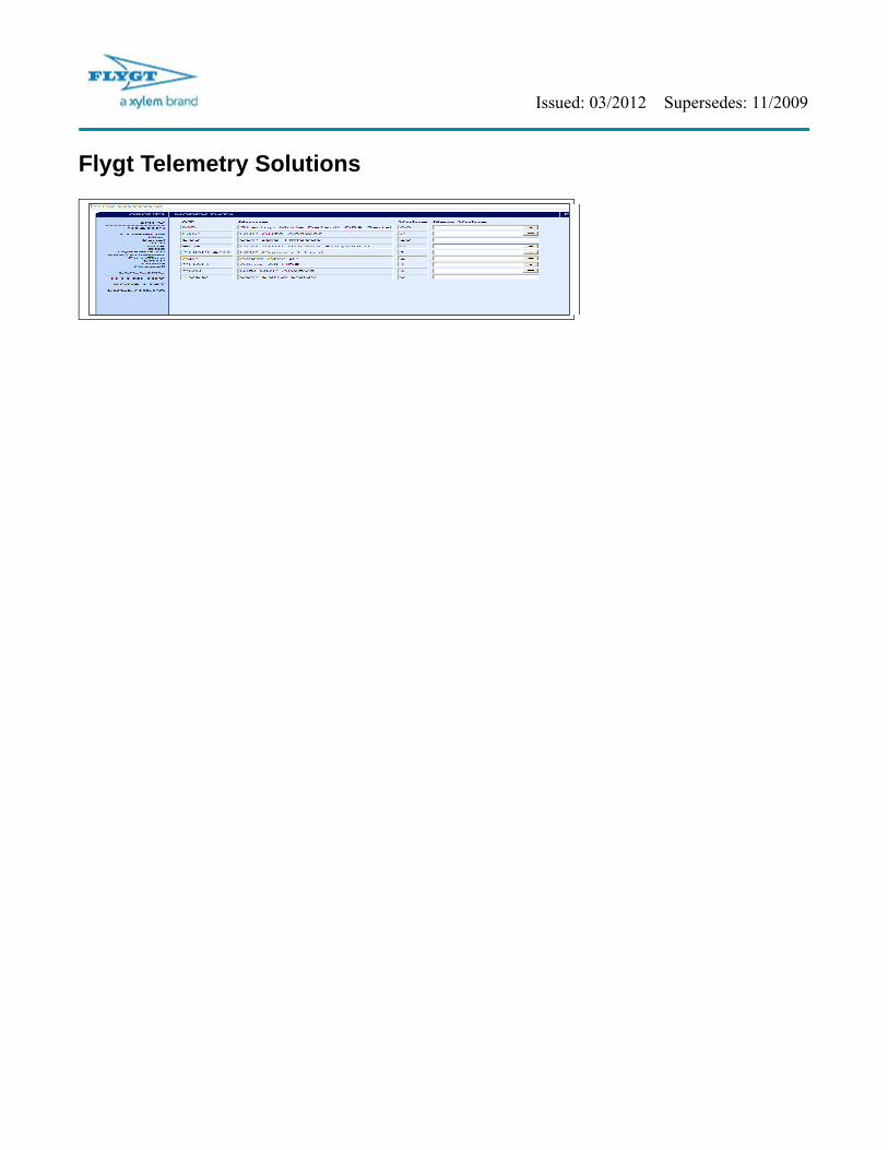
Select the COM port you are connected to and click “OK” If the Password field gets cleared, the default password is 12345. A sample file has been created with many of the settings below shown; to use it first acquire it from your local Flygt M&C Specialist, or download it from the M&C Sharepoint site if you are a Flygt employee. To do this click Load, then select the file from your hard drive.
Note that you will still have to set the Device Port, Destination Port and Network User ID / Password / Static IP settings, as well as the APN settings on the EDGE/HSPA tab. Below is a listing of all recommended settings, screen by screen in the AceManager software.
Depending on the SIM carrier, either the Static IP or Network User ID and Network Password must be entered to connect to the network.
Address / port to transmit data to. This is used in AquaView Setup, Port “ID” field.
Port Airlink Modem is listening on. This is used in AquaView Setup, RTU “Address” field
Issued: 03/2012 Supersedes: 11/2009
Flygt Telemetry Solutions
Issued: 03/2012 Supersedes: 11/2009
Flygt Telemetry Solutions
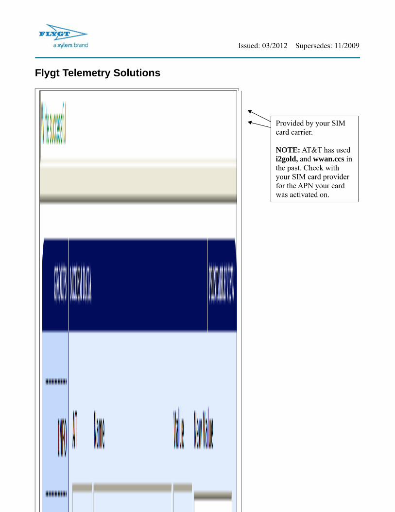
Provided by your SIM card carrier. NOTE: AT&T has used i2gold, and wwan.ccs in the past. Check with your SIM card provider for the APN your card was activated on.

Issued: 03/2012 Supersedes: 11/2009
Flygt Telemetry Solutions
Issued: 03/2012 Supersedes: 11/2009
Flygt Telemetry Solutions
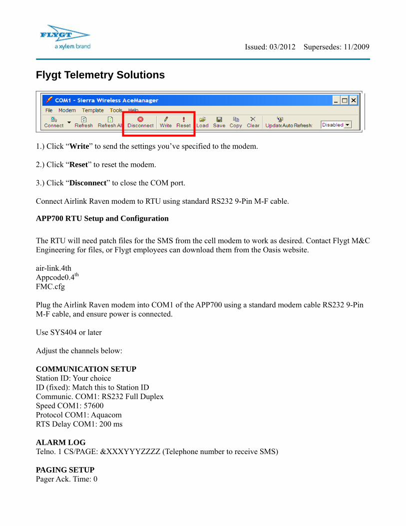
1.) Click “Write” to send the settings you’ve specified to the modem. 2.) Click “Reset” to reset the modem. 3.) Click “Disconnect” to close the COM port. Connect Airlink Raven modem to RTU using standard RS232 9-Pin M-F cable.
APP700 RTU Setup and Configuration
The RTU will need patch files for the SMS from the cell modem to work as desired. Contact Flygt M&C Engineering for files, or Flygt employees can download them from the Oasis website. air-link.4th Appcode0.4th
FMC.cfg Plug the Airlink Raven modem into COM1 of the APP700 using a standard modem cable RS232 9-Pin M-F cable, and ensure power is connected. Use SYS404 or later Adjust the channels below: COMMUNICATION SETUP Station ID: Your choice ID (fixed): Match this to Station ID Communic. COM1: RS232 Full Duplex Speed COM1: 57600 Protocol COM1: Aquacom RTS Delay COM1: 200 ms ALARM LOG Telno. 1 CS/PAGE: &XXXYYYZZZZ (Telephone number to receive SMS) PAGING SETUP Pager Ack. Time: 0
Issued: 03/2012 Supersedes: 11/2009
Flygt Telemetry Solutions Paging System: GSM-SMS APP521 RTU Setup and Configuration COMMUNICATION.. Station number / id: Choose desired Station Number
Communication COM1: RS232 FDX
Speed COM1: 9600
Parity COM1: None
Protocol COM1: AquaCom Fixed
RTS Delay COM1: 200 ms
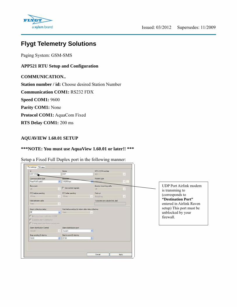
AQUAVIEW 1.60.01 SETUP ***NOTE: You must use AquaView 1.60.01 or later!! *** Setup a Fixed Full Duplex port in the following manner:
UDP Port Airlink modem is transming to (corresponds to “Destination Port” entered in Airlink Raven setup) This port must be unblocked by your firewall.
Issued: 03/2012 Supersedes: 11/2009
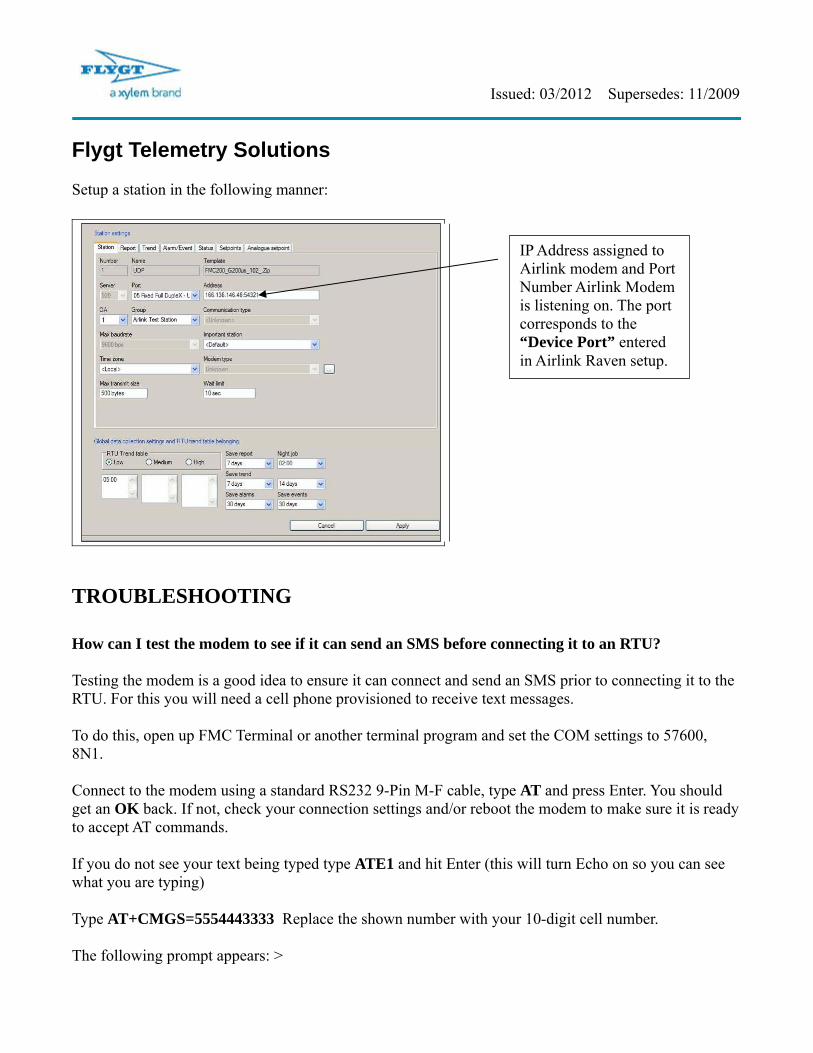
Flygt Telemetry Solutions Setup a station in the following manner:
TROUBLESHOOTING How can I test the modem to see if it can send an SMS before connecting it to an RTU? Testing the modem is a good idea to ensure it can connect and send an SMS prior to connecting it to the RTU. For this you will need a cell phone provisioned to receive text messages. To do this, open up FMC Terminal or another terminal program and set the COM settings to 57600, 8N1. Connect to the modem using a standard RS232 9-Pin M-F cable, type AT and press Enter. You should get an OK back. If not, check your connection settings and/or reboot the modem to make sure it is ready to accept AT commands. If you do not see your text being typed type ATE1 and hit Enter (this will turn Echo on so you can see what you are typing) Type AT+CMGS=5554443333 Replace the shown number with your 10-digit cell number. The following prompt appears: >
IP Address assigned to Airlink modem and Port Number Airlink Modem is listening on. The port corresponds to the “Device Port” entered in Airlink Raven setup.

Issued: 03/2012 Supersedes: 11/2009
Flygt Telemetry Solutions Type your test message, press Enter, then Ctrl-Z. The modem should respond with OK and you should get the text message on your phone within 15 seconds or so. Here’s a sample screen of the entire procedure:
I’ve set up the Airlink Files in the Flygt FMC/APP Controller, but it doesn’t page out! Check to see if the files are being loaded properly. Connect a null modem cable RS232 9-Pin F-F cable to COM2 on the APP700 controller and use a terminal program with COM settings 57600, 8N1. Reboot the controller and watch the screen:

Issued: 03/2012 Supersedes: 11/2009
Flygt Telemetry Solutions
The error message of “Cannot put READFMCDOTCFG into Warm. .” indicates there is a problem with your files (they’re read only, have been corrupted, etc). Redownloading the correct files and restarting should remove this error (note the message is gone in the screen below)

Issued: 03/2012 Supersedes: 11/2009
Flygt Telemetry Solutions How can I trace communication to see if the text messaging is working? Connect a null modem cable RS232 9-Pin F-F cable to COM2 on the APP700 controller and use a terminal program with COM settings 57600, 8N1. Type 1 0 strace-on and press Enter. You will now see the communication trace of all activity on COM1 of the APP700. Trigger an alarm and watch to see if the modem gets initialized and a text message is sent out. I keep getting a “Bad Param. Dist.” error in the RTU! This error means the Airlink Modem is unable to transmit the SMS alarm, either because of incorrect communication parameters, lack of signal strength, or an Aquaview connection being present and transferring data while the modem is attempting to send an SMS.