telescopic crawler crane - sin heng heavy … telescopic crawler crane 17-1, higashigotanda 2-chome,...
TRANSCRIPT
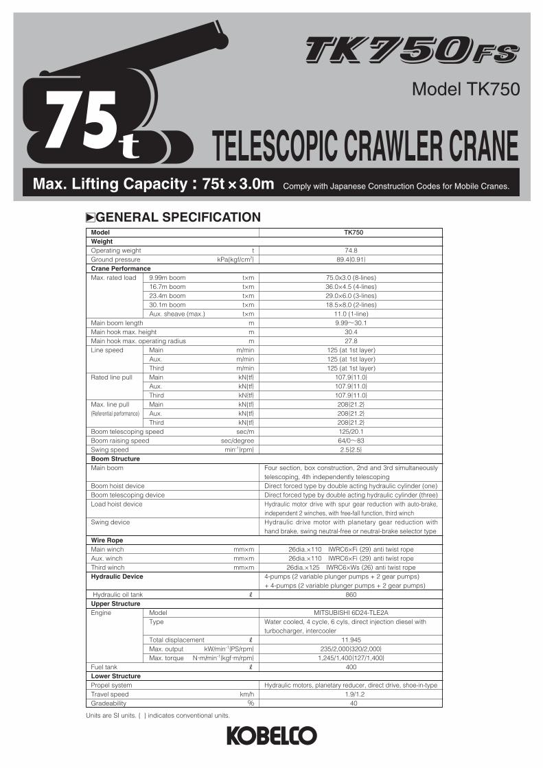
Model TK750
Max. Lifting Capacity : 75t × 3.0m Comply with Japanese Construction Codes for Mobile Cranes.
TELESCOPIC CRAWLER CRANE75
17-1, Higashigotanda 2-chome, Shinagawa-ku,Tokyo 141-8626 JAPAN
Note: This catalog may contain photographs of machines with specifications, attachments and optional equipment not certified for operation in your country. Please consult KOBELCO for those items you may require. Due to our policy of continual product improvements all designs and specifications are subject to change without advance notice.Copyright by KOBELCO CRANES CO., LTD. No part of this catalog may be reproduced in any manner without notice.
Tel: +81-3-5789-2130 Fax: +81-3-5789-3372URL: http://www.kobelco-cranes.com/
Bulletin No. TK750FS-SPEC-1 130101F Printed in Japan
Inquiries To :
KOBELCO is the corporate mark used by Kobe Steel on a variety of productsand in the names of a number of Kobe Steel Group companies.
kGENERAL DIMENSIONS (Unit : mm)
5,130
5,990
2,690
3,185
1,1003,110
R 4,100 2,850
2,0752,260
Boom length : 9.99m~30.1m12,885
940
4,830 (Extended)
990
1,595
800
3,200 (Retracted)
3,190
kSTANDARD EQUIPMENTUpper Structure/Lower Structure
Third drum : wire rope 26dia. x 125m, with free-fall
Counterweight : 17.2t (9.0t + 8.2t)
Crawlerweight : 2.0t (0.5t x 4)
800mm shoe crawlers
165G51 battery
Electric hand throttle grip
Variable main/aux. speed controller
Side deck (for cab) : 300mm (W) x 970mm (L)
Anti-slip sheet
Tools (for routine maintenance)
Lubrication device
Tool box (equipped on right-side guard)
Three front working lights
Two back mirrors
Cab
Air conditioner
Convenient compartment
Cup holder
AM/FM Radio
Ashtray
Cigarette lighter
Intermittent windshield wiper with window washer (roof, front and lower front window)
Sun visor
Roof blind
Tinted glass
Floor mat (cloth)
Foot pedal cover (rubber)
Shoe tray
Safety Device
Over-load prevention device (auto stop function)
Release prevention key for hook over-hoist prevention device
LCD Multi-display (shows gauges and warning signs)
Hook over-hoist auto-stop device
Operating zone limit device
Safety lever lock
Propel lever lock
Manual drum safety pawl (main, aux.)
Negative brake in lever neutral-position (main, aux., third, travel)
Brake fail safe mechanism (main, aux., third, travel)
Service brake pedal lock (main, aux.)
Lamp for neutral-free/brake select switch (main, aux.)
Neutral-free/brake select switch (main, aux.)
Neutral brake release prevention key (main, aux.)
Brake activating device for engine stop
Hydraulically safety valve
Boom telescoping default operation prevention device (Automatic)
Boom telescoping safety device
Boom hoist safety device
Over hook limit device
Sling wire lock
Horn
Swing lock pin
Swing flashers
Swing warning buzzer
Voice alarm for travel/swing (over hoist, over load, crawler extension)
Level gauge
kOPTIONAL EQUIPMENT4-spool valve : Max. discharge pressure 17.2MPa{175kgf/cm²}
Max. discharge flow 40liters/min
Outlet for Auger : Max. output 145kW{200PS}
Max. discharge pressure 30.0MPa{305kgf/cm²}
Max. discharge flow 425liters/min (with oil flow select switch)
Hydraulic tagline : 10dia. x 45m
Lifting capacity set : insert counterweight/without counterweight
Swing neutral brake : cannot select swing neutral free
11-ton light swivel ball hook : 100kg
Counterweight self-removal device
Trans-lifter
Foot acceleration : right hand
Boom hoist pedal : right hand (not available to equipt with foot acceleration)
Engine rpm fix switch : 4-steps
Cab roof guard
Side catwalk (without handrail) : 300mm (W) x 3,710mm (L)-right hand/4,090mm (L)-left hand
Color monitoring camera (backward) with monitor
Monitoring camera for main/aux. with lightning
Overload alarm lamp (3 colors, square shape)
One way call
Electric fuel pump
Fire extinguisher
Electric fan
kGENERAL SPECIFICATIONModelWeightOperating weight tGround pressure kPa{kgf/cm2}Crane PerformanceMax. rated load 9.99m boom t×m
16.7m boom t×m23.4m boom t×m30.1m boom t×mAux. sheave (max.) t×m
Main boom length mMain hook max. height mMain hook max. operating radius mLine speed Main m/min
Aux. m/minThird m/min
Rated line pull Main kN{tf}Aux. kN{tf}Third kN{tf}
Max. line pull Main kN{tf}(Referential performance) Aux. kN{tf}
Third kN{tf}Boom telescoping speed sec/mBoom raising speed sec/degreeSwing speed min-1{rpm}Boom StructureMain boom
Boom hoist deviceBoom telescoping deviceLoad hoist device
Swing device
Wire RopeMain winch mm×mAux. winch mm×mThird winch mm×mHydraulic Device
Hydraulic oil tank R
Upper StructureEngine Model
Type
Total displacement R
Max. output kW/min-1{PS/rpm}Max. torque N・m/min-1{kgf・m/rpm}
Fuel tank R
Lower StructurePropel systemTravel speed km/hGradeability %
TK750
74.889.4{0.91}
75.0x3.0 (8-lines)36.0×4.5 (4-lines)29.0×6.0 (3-lines)18.5×8.0 (2-lines)
11.0 (1-line)9.99〜30.1
30.427.8
125 (at 1st layer)125 (at 1st layer)125 (at 1st layer)
107.9{11.0}107.9{11.0}107.9{11.0}208{21.2}208{21.2}208{21.2}125/20.164/0〜832.5{2.5}
Four section, box construction, 2nd and 3rd simultaneouslytelescoping, 4th independently telescopingDirect forced type by double acting hydraulic cylinder (one)Direct forced type by double acting hydraulic cylinder (three)Hydraulic motor drive with spur gear reduction with auto-brake,independent 2 winches, with free-fall function, third winchHydraulic drive motor with planetary gear reduction withhand brake, swing neutral-free or neutral-brake selector type
26dia.×110 IWRC6×Fi (29) anti twist rope26dia.×110 IWRC6×Fi (29) anti twist rope
26dia.×125 IWRC6×Ws (26) anti twist rope4-pumps (2 variable plunger pumps + 2 gear pumps) + 4-pumps (2 variable plunger pumps + 2 gear pumps)
860
MITSUBISHI 6D24-TLE2AWater cooled, 4 cycle, 6 cyls, direct injection diesel with turbocharger, intercooler
11.945235/2,000{320/2,000}
1,245/1,400{127/1,400}400
Hydraulic motors, planetary reducer, direct drive, shoe-in-type1.9/1.2
40
Units are SI units. { } indicates conventional units.

⑴Rated load do not exceed 78% of the tipping loads with machine sethorizontally on a firm and level ground, safety the specified stabilityover the front, and include weight of hook block (s) and other handlingaccessories.Ratings shown in are based on the machine’s structuralstrength, and others are determined by the machine’s stability.
⑵Rated loads shown are based on freely suspended loads and make noallowance for such factors as wind effect on lifted load, ground condi-tions out-of-level. Operating speeds or any other condition that couldbe detrimental to the safe operation of this equipment, the operator,therefore, has the responsibility to judge the existing conditions andreduce lifted loads and operating speeds accordingly.
⑶Operating radius is the horizontal distance from centerline of rotation to avertical line through the center of gravity of the load. Operating radiusgiven in the charts allow for loaded boom delfection and reduce liftedloads and operating speeds accordingly.
⑷Both crawlers should be fully extended.
⑸The ratings of the auxiliary sheave are the same as the main boom rat-ings, but should not exceed 11,000kg. Ratings of the auxiliary sheaveare calculated by deducting from the main boom ratings 75 ton hookweight (950kg) with the main boom extended ranging from 9.99m to16.7m, and 50 ton hook weight (860kg) with the main boom extendedover 16.7m up to its maximum length.
kLIFTING CAPACITYm Note
⑹The main boom ratings shall be applied to the third drum ratings, butthe jib ratings shall not exceed 11,000kg.
⑺To determine load ratings that fall between those shown in the charts,proceed as follows :a) For boom lengths not listed use rating for next longer boom length
or next shorter boom length, whichever is smaller.b) For load radii not shown, use rating for next larger radius.
⑻At radii and boom lengths where no ratings are shown on chart, opera-tion is not intended nor approved.
⑼Standard hoist reevings are shown below. Rated single-line pull mustnot exceed 11,000kg.
⑽Third drum hoist reevings are shown below. Rated single-line pull mustnot exceed 11,000kg.
⑾In order to prevent a load from falling down to mistake of operation, donot use free-fall in crane operation.
Boom length
Hook
No. of reeving
9.99m
8
16.7m
75-ton
4
23.4m
3
30.1m
50-ton 32-ton
2
Hooks
Weight
75-ton
950kg
32-ton
550kg
50-ton
860kg
11-ton
300kg
11-ton (light)
100kg
Boom length
Hook
No. of reeving
9.99m
8
16.7m
75-ton
4
23.4m
3
30.1m
50-ton 32-ton
2
Note : 11-ton light swivel ball hook is option.
0゚
5゚
10゚
15゚
20゚
25゚
30゚
35゚
40゚
45゚
50゚
55゚
60゚
65゚
70゚75゚
80゚83゚
30.1m Boom
23.4m Boom
16.7m Boom
9.99m Boom
40
30
20
10
0 10 20 30
Hei
gh
t ab
ove
gro
un
d (
m)
Distance from center of rotation (m) (Operating radius)
kWORKING RANGES (Unit : m)
Ratings shown in are determined by the strength of the boom or other structural components.
m With 17.2 ton counterweight
Boom length(m)Working
radius (m)
Boom length(m) Working
radius (m)
(Unit : metric ton)
3.0 3.5 3.7 4.0 4.5 5.0 5.5 6.0 6.5 7.0 7.5 7.7 8.0 8.5 9.0 9.5
10.0 11.0 12.0 13.0 14.0 14.4 15.0 16.0 17.0 18.0 19.0 20.0 21.0 21.1 22.0 23.0 24.0 25.0 26.0 27.0 27.8
3.0 3.5 3.7 4.0 4.5 5.0 5.5 6.0 6.5 7.0 7.5 7.7 8.0 8.5 9.0 9.5
10.0 11.0 12.0 13.0 14.0 14.4 15.0 16.0 17.0 18.0 19.0 20.0 21.0 21.1 22.0 23.0 24.0 25.0 26.0 27.0 27.8
75.00 60.00 56.00 51.00 44.50 39.50 36.00 34.40 31.40 28.90 26.30 25.10
36.00 36.00 36.00 36.00 36.00 35.00 33.00 30.70 29.80 27.20 25.10 24.40 23.30 21.20 19.40 17.90 16.50 14.20 12.40 11.00
9.70 9.30
29.00 29.00 29.00 29.00 29.00 29.00 29.00 29.00 26.10 23.20 21.60 20.90 20.00 19.00 18.10 17.00 16.30 14.10 12.30 10.80
9.50 9.10 8.50 7.60 6.60 6.20 5.60 5.00 4.60 4.50
18.50 18.50 18.50 18.50 18.50 18.50 18.50 18.50 18.50 18.50 18.50 18.50 18.50 17.00 15.50 14.50 13.50 12.80 11.80 11.00
9.90 9.50 9.00 8.20 7.40 6.70 6.10 5.50 5.10 5.00 4.60 4.20 3.90 3.50 3.20 2.90 2.70
Max. boom angleMin. boom angle
82.1°0°
79.8°0°
75.6°0°
65.0°0°
Max. boom angleMin. boom angle
9.99 16.7 23.4 30.1Ratings shown in are determined by the strength of the boom or other structural components.
m With 8.2 ton counterweight (optional setting)
Boom length(m)Working
radius (m)
Boom length(m) Working
radius (m)
(Unit : metric ton)
3.0 3.5 3.7 4.0 4.5 5.0 5.5 6.0 6.5 7.0 7.5 7.7 8.0 8.5 9.0 9.5
10.0 11.0 12.0 13.0 14.0 14.4 15.0 16.0 17.0 18.0 19.0 20.0 21.0 21.1 22.0 23.0 24.0 25.0 26.0
3.0 3.5 3.7 4.0 4.5 5.0 5.5 6.0 6.5 7.0 7.5 7.7 8.0 8.5 9.0 9.5
10.0 11.0 12.0 13.0 14.0 14.4 15.0 16.0 17.0 18.0 19.0 20.0 21.0 21.1 22.0 23.0 24.0 25.0 26.0
75.00 60.00 56.00 51.00 44.50 37.20 31.30 26.90 23.50 20.75 18.55 17.75
36.00 36.00 36.00 36.00 36.00 35.00 30.90 26.50 23.10 20.35 18.10 17.35 16.30 14.75 13.40 12.25 11.20
9.55 8.20 7.10 6.20 5.90
29.00 29.00 29.00 29.00 29.00 29.00 29.00 26.25 22.85 20.10 17.85 17.15 16.05 14.50 13.15 12.00 11.00
9.30 8.00 6.90 5.95 5.65 5.20 4.55 4.00 3.50 2.95 2.55 2.15 2.10
18.50 18.50 18.50 18.50 18.50 18.50 18.50 18.50 18.50 18.50 18.50 18.50 16.75 15.15 13.80 12.65 11.65
9.95 8.55 7.45 6.55 6.20 5.75 5.10 4.50 4.00 3.55 3.15 2.75 2.70 2.40 2.05 1.75 1.50 1.25
65.0°0°
75.6°0°
79.8°0°
82.1°22.4°
Max. boom angleMin. boom angle
9.99 16.7 23.4 30.1
m Without counterweight (optional setting)
Boom length(m)Working
radius (m)
Boom length(m) Working
radius (m)
(Unit : metric ton)
3.0 3.5 3.7 4.0 4.5 5.0 5.5 6.0 6.5 7.0 7.5 7.7 8.0 8.5 9.0 9.5
10.0 11.0 12.0 13.0 14.0 14.4
3.0 3.5 3.7 4.0 4.5 5.0 5.5 6.0 6.5 7.0 7.5 7.7 8.0 8.5 9.0 9.5
10.0 11.0 12.0 13.0 14.0 14.4
30.00 30.00 30.00 30.00 30.00 24.50 20.45 17.45 15.10 13.25 11.75 11.20
20.00 20.00 20.00 20.00 20.00 20.00 20.00 17.05 14.75 12.90 11.35 10.80 10.10
9.05 8.10 7.35 6.65 5.50 4.60 3.85 3.25 3.05
Max. boom angleMin. boom angle
65.0°0°
75.6°0°
Max. boom angleMin. boom angle
9.99 16.7
Max. boom angleMin. boom angle

Model TK750
Max. Lifting Capacity : 75t × 3.0m Comply with Japanese Construction Codes for Mobile Cranes.
TELESCOPIC CRAWLER CRANE75
17-1, Higashigotanda 2-chome, Shinagawa-ku,Tokyo 141-8626 JAPAN
Note: This catalog may contain photographs of machines with specifications, attachments and optional equipment not certified for operation in your country. Please consult KOBELCO for those items you may require. Due to our policy of continual product improvements all designs and specifications are subject to change without advance notice.Copyright by KOBELCO CRANES CO., LTD. No part of this catalog may be reproduced in any manner without notice.
Tel: +81-3-5789-2130 Fax: +81-3-5789-3372URL: http://www.kobelco-cranes.com/
Bulletin No. TK750FS-SPEC-1 130101F Printed in Japan
Inquiries To :
KOBELCO is the corporate mark used by Kobe Steel on a variety of productsand in the names of a number of Kobe Steel Group companies.
kGENERAL DIMENSIONS (Unit : mm)
5,130
5,990
2,690
3,185
1,1003,110
R 4,100 2,850
2,0752,260
Boom length : 9.99m~30.1m12,885
940
4,830 (Extended)
990
1,595
800
3,200 (Retracted)
3,190
kSTANDARD EQUIPMENTUpper Structure/Lower Structure
Third drum : wire rope 26dia. x 125m, with free-fall
Counterweight : 17.2t (9.0t + 8.2t)
Crawlerweight : 2.0t (0.5t x 4)
800mm shoe crawlers
165G51 battery
Electric hand throttle grip
Variable main/aux. speed controller
Side deck (for cab) : 300mm (W) x 970mm (L)
Anti-slip sheet
Tools (for routine maintenance)
Lubrication device
Tool box (equipped on right-side guard)
Three front working lights
Two back mirrors
Cab
Air conditioner
Convenient compartment
Cup holder
AM/FM Radio
Ashtray
Cigarette lighter
Intermittent windshield wiper with window washer (roof, front and lower front window)
Sun visor
Roof blind
Tinted glass
Floor mat (cloth)
Foot pedal cover (rubber)
Shoe tray
Safety Device
Over-load prevention device (auto stop function)
Release prevention key for hook over-hoist prevention device
LCD Multi-display (shows gauges and warning signs)
Hook over-hoist auto-stop device
Operating zone limit device
Safety lever lock
Propel lever lock
Manual drum safety pawl (main, aux.)
Negative brake in lever neutral-position (main, aux., third, travel)
Brake fail safe mechanism (main, aux., third, travel)
Service brake pedal lock (main, aux.)
Lamp for neutral-free/brake select switch (main, aux.)
Neutral-free/brake select switch (main, aux.)
Neutral brake release prevention key (main, aux.)
Brake activating device for engine stop
Hydraulically safety valve
Boom telescoping default operation prevention device (Automatic)
Boom telescoping safety device
Boom hoist safety device
Over hook limit device
Sling wire lock
Horn
Swing lock pin
Swing flashers
Swing warning buzzer
Voice alarm for travel/swing (over hoist, over load, crawler extension)
Level gauge
kOPTIONAL EQUIPMENT4-spool valve : Max. discharge pressure 17.2MPa{175kgf/cm²}
Max. discharge flow 40liters/min
Outlet for Auger : Max. output 145kW{200PS}
Max. discharge pressure 30.0MPa{305kgf/cm²}
Max. discharge flow 425liters/min (with oil flow select switch)
Hydraulic tagline : 10dia. x 45m
Lifting capacity set : insert counterweight/without counterweight
Swing neutral brake : cannot select swing neutral free
11-ton light swivel ball hook : 100kg
Counterweight self-removal device
Trans-lifter
Foot acceleration : right hand
Boom hoist pedal : right hand (not available to equipt with foot acceleration)
Engine rpm fix switch : 4-steps
Cab roof guard
Side catwalk (without handrail) : 300mm (W) x 3,710mm (L)-right hand/4,090mm (L)-left hand
Color monitoring camera (backward) with monitor
Monitoring camera for main/aux. with lightning
Overload alarm lamp (3 colors, square shape)
One way call
Electric fuel pump
Fire extinguisher
Electric fan
kGENERAL SPECIFICATIONModelWeightOperating weight tGround pressure kPa{kgf/cm2}Crane PerformanceMax. rated load 9.99m boom t×m
16.7m boom t×m23.4m boom t×m30.1m boom t×mAux. sheave (max.) t×m
Main boom length mMain hook max. height mMain hook max. operating radius mLine speed Main m/min
Aux. m/minThird m/min
Rated line pull Main kN{tf}Aux. kN{tf}Third kN{tf}
Max. line pull Main kN{tf}(Referential performance) Aux. kN{tf}
Third kN{tf}Boom telescoping speed sec/mBoom raising speed sec/degreeSwing speed min-1{rpm}Boom StructureMain boom
Boom hoist deviceBoom telescoping deviceLoad hoist device
Swing device
Wire RopeMain winch mm×mAux. winch mm×mThird winch mm×mHydraulic Device
Hydraulic oil tank R
Upper StructureEngine Model
Type
Total displacement R
Max. output kW/min-1{PS/rpm}Max. torque N・m/min-1{kgf・m/rpm}
Fuel tank R
Lower StructurePropel systemTravel speed km/hGradeability %
TK750
74.889.4{0.91}
75.0x3.0 (8-lines)36.0×4.5 (4-lines)29.0×6.0 (3-lines)18.5×8.0 (2-lines)
11.0 (1-line)9.99〜30.1
30.427.8
125 (at 1st layer)125 (at 1st layer)125 (at 1st layer)
107.9{11.0}107.9{11.0}107.9{11.0}208{21.2}208{21.2}208{21.2}125/20.164/0〜832.5{2.5}
Four section, box construction, 2nd and 3rd simultaneouslytelescoping, 4th independently telescopingDirect forced type by double acting hydraulic cylinder (one)Direct forced type by double acting hydraulic cylinder (three)Hydraulic motor drive with spur gear reduction with auto-brake,independent 2 winches, with free-fall function, third winchHydraulic drive motor with planetary gear reduction withhand brake, swing neutral-free or neutral-brake selector type
26dia.×110 IWRC6×Fi (29) anti twist rope26dia.×110 IWRC6×Fi (29) anti twist rope
26dia.×125 IWRC6×Ws (26) anti twist rope4-pumps (2 variable plunger pumps + 2 gear pumps) + 4-pumps (2 variable plunger pumps + 2 gear pumps)
860
MITSUBISHI 6D24-TLE2AWater cooled, 4 cycle, 6 cyls, direct injection diesel with turbocharger, intercooler
11.945235/2,000{320/2,000}
1,245/1,400{127/1,400}400
Hydraulic motors, planetary reducer, direct drive, shoe-in-type1.9/1.2
40
Units are SI units. { } indicates conventional units.