televes catalogue (pdf 15mb)
TRANSCRIPT

1 Product Catalogue
Antennas
u FM/BIII antennas .............................................................................5 u DAB/Combined antennas ............................................................6 u UHF antennas ..................................................................................8 u Special combined antennas ....................................................12 u Indoor antennas............................................................................16
Satellite
u Satellite dishes ..............................................................................19 u LNB ....................................................................................................20 u Feedhorns and supports............................................................21
Mechanical accessories
u Masts ................................................................................................25 u Supports and clamps for mast ................................................25 u Cables................................................................................................26 u Accessories......................................................................................26 u Towers ..............................................................................................27
Electronics
u Mast devices ..................................................................................35 u Domestic amplifiers ....................................................................38 u Picokom series ..............................................................................40 u Accessories......................................................................................42 u Microkom series ............................................................................43 u Minikom series ..............................................................................44 u DTKom ..............................................................................................46 u Programmable headend............................................................50 u T12 system ......................................................................................53 u T0X Headend equipment ..........................................................55 u CDC system ....................................................................................67 u T05 Headend equipment ..........................................................69 u Multiswitches ................................................................................77 u Tools and sofware ...................................................................... 88
Optical Fiber
u Optical Output LNB and Optical Converters ......................91 u Optical transmitter ......................................................................93 u Optical receiver ............................................................................95 u Outdoor optical fiber receiver ................................................96 u Optical splitter ..............................................................................97 u Optical accessories ......................................................................98 u Optical cables ................................................................................98
Distribution and accessories
u Splitters/ Mixers ..........................................................................101 u Indoor Splitters ..........................................................................102 u Indoor taps ..................................................................................105 u Outlets............................................................................................108 u Connectors ..................................................................................110 u Coaxial cables ..............................................................................113
DTH receivers
u Terrestrial Digital Receiver......................................................118 u Satellite Digital Receiver ........................................................120
Meters and tools
u H45 ................................................................................................125
Coaxdata
u Coaxdata........................................................................................133
Home accessories
u Digidom ........................................................................................139 u Domestic modulator ................................................................141
Technical data and annexes
u Conversion tables ......................................................................145 u TV frequency bands ..................................................................145 u Radio frequency standards ....................................................146 u TV standards ................................................................................147 u Channel - frequency tables ....................................................148 u Glossary of measurements ....................................................149 u Index by references .................................................................152 u AENOR certificate ......................................................................154
Index

2 Product Catalogue

Made of aluminium and ABS plastic, Televés line of antennas are constructed to resist the har-
dest climatic conditions such as UV radiation, drastic changes of temperature and rust.
ANTENNAS

4 Product Catalogue
ANTENNAS
5 Product Catalogue
FM/BIII
270 90
180
0Plane EPlane H
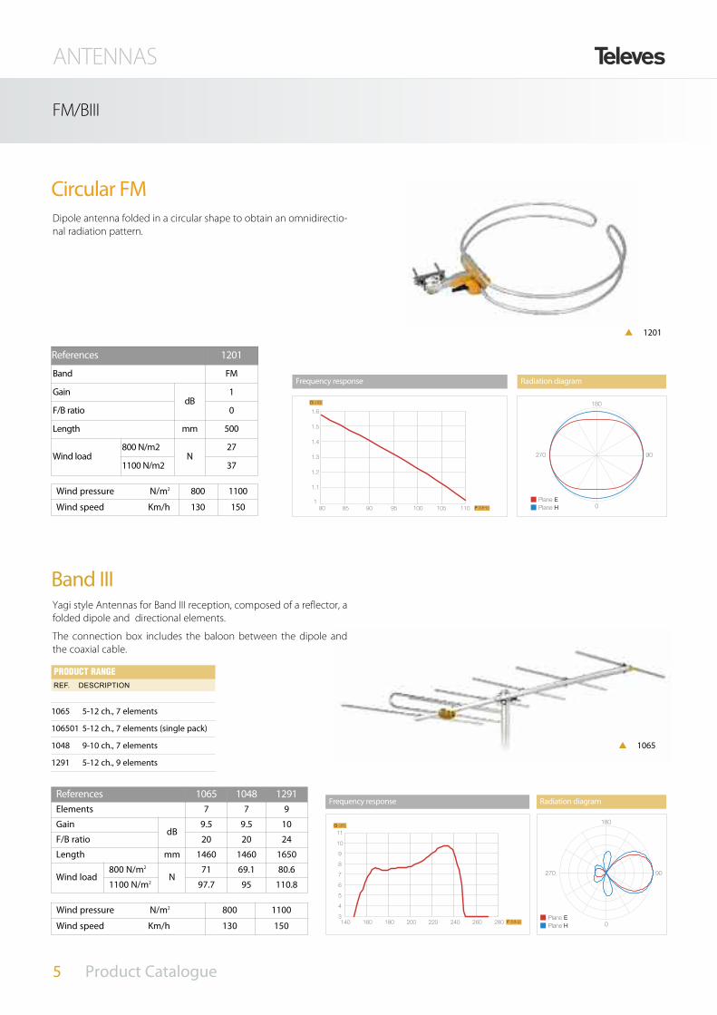
Circular FM
p 1201
Radiation diagram
References 1201
Band FM
GaindB
1
F/B ratio 0
Length mm 500
Wind load800 N/m2
N27
1100 N/m2 37
Wind pressure N/m2 800 1100
Wind speed Km/h 130 150 110 F (MHz)1
G (dB)
1.6
1.5
1.4
1.3
1.2
1.1
10510095908580
Frequency response
Dipole antenna folded in a circular shape to obtain an omnidirectio-nal radiation pattern.
Band III
References 1065 1048 1291Elements 7 7 9
GaindB
9.5 9.5 10
F/B ratio 20 20 24
Length mm 1460 1460 1650
Wind load800 N/m2
N 71 69.1 80.6
1100 N/m2 97.7 95 110.8
280 F (MHz)
G (dB)
3
4
5
6
7
8
9
10
11
140 160 180 200 220 240 260
270 90
180
0Plane EPlane H
Frequency response Radiation diagram
Wind pressure N/m2 800 1100
Wind speed Km/h 130 150
Yagi style Antennas for Band III reception, composed of a reflector, afolded dipole and directional elements.
The connection box includes the baloon between the dipole andthe coaxial cable.
1065 5-12 ch., 7 elements
106501 5-12 ch., 7 elements (single pack)
1048 9-10 ch., 7 elements
1291 5-12 ch., 9 elements
Ref. DeSCRIPTION PRODUCT RANGE
p 1065

ANTENNAS
6 Product Catalogue
300 F (MHz)250200150100
3
2
5
4
7
6
9
8
G (dB)
270 90
180
0Plane EPlane H
DAB
References 1050
Band DAB/BIII190-232 MHz
GaindB
8
F/B ratio >15
Length mm 555
Wind load800 N/m2
N 36.5
1100 N/m2 50.2
Frequency response Radiation diagram
Wind pressure N/m2 800 1100
Wind speed Km/h 130 150
Specially designed for DAB reception (Digital Audio Broadcasting).
It is a three-element antenna (reflector, dipole and directive element)that covers the whole reserved band for DAB transmissions.
Includes the baloon in the connection box.
1050 DAB, 3 elements
Ref. DeSCRIPTION PRODUCT RANGE
p 1050
p 1030
VHF/UHF
1030 Logaritmic BIII/UHF
Ref. DeSCRIPTION PRODUCT RANGE
Designed for Band III and UHF reception.
The 1030 is a logaritmic antenna composed of a number of activedipoles, each of them tuned to a diferent frequency. The result is abroadband antenna.
Radiation diagram
VHF UHF
270 90
180
0Plano EPlano H
270 90
180
0Plano EPlano H
1030 1030
References 1030
Band 5-12/21-69
Gain dB 8.5/10Length mm 900
Wind load800 N/m2
N 33.6
1100 N/m2 46.2
DAB/COMBINED ANTENNAS

ANTENNAS
7 Product Catalogue
COMBINED ANTENNAS
Dat HD Boss Mix
149610 DAT HD BOSS Mix
149611 DAT HD BOSS Mix single pack
Ref. DeSCRIPTION PRODUCT RANGE
Mixed antenna for BIII (174-230) and UHF (470-862) reception.
The UHF antenna is a Yagi style antenna of 39 elements, with 24director elements distributed in a angled array of three rows, givinghigh directivity and balanced bandwidth.
The part for the BIII is also a Yagi style antenna of 3 elements, with1 dipole and 2 reflectors.
The structure is based on the DAT HD antenna with additional BIIIelements.
The BossTech is activated or not depending on the power supplyvoltage. The gain regulation affects both to the UHF, and the BIII sig-nals.
FULLY SHIELDED
F connector
new
Wind pressure N/m2 800 1100Wind speed Km/h 130 150
References 149610/149611
BandPassive Active
5-12 21-69 5-12 21-69Gain dB 8.5 16 21 28 max. Output level dBµV - Auto-regulatedNoise figure dB - 2 Powering voltage Vcc 0 12-24 Consumption mA - 40 max. Length mm 1112
Wind load800 N/m2
N 135
1100 N/m2 185
p 149610
149601

ANTENNAS
8 Product Catalogue
UHF
1495 DAT HD BOSS multipack
149501 DAT HD BOSS single pack
149503 DAT HD BOSS Single Pack (60 mm bracket)
Ref. DeSCRIPTION PRODUCT RANGE
270 90
180
0900 F (MHz)
G (dB)
850800750700650600550500450
17
11
12
13
14
15
16
Reference 1495Mode Passive ActiveBands UHFGain 17 dB 29 dB máx.Output Level --- Auto-regulatedNoise figure - 2 dB tip. Recommended signal level > 75 dBµV < 75 dBµV Powering 0 Vcc 12-24 VccConsumption - 40 mABeamwidth 30ºWindload 120N (130 Km/h) 165N (150 Km/h)
Dat HD Boss
with automatic signal balance
TOO WEAK
TOO STRONG
PERFECT SIGNAL
The DAT HD is designed to function in automatic mode (Boss-Techactivated) or passive mode.
Do not worry about signal strenght just align antenna and the Boss-Tech device will automatically adjust the output signal to the opti-mum level (*)
Whether in automatic or passive mode, the DAT HD offers exclusivefunctionality to maximize the reception of the DTT.
Frequency response Radiation diagram
p 1495

ANTENNAS
9 Product Catalogue
UHF
A D I T I O N A L F E A T U R E S
Newly patented dipole that greatlyimproves the reception marginsthroughout the complete terrestrial band
The asymmetrical directors providethe perfect radiation diagram toreduce ECHOES
Fully shielded BOSS-Techenclosure to protect againstimpulsive noise
State-of-the-art Multilayertechnology providing highest stabilityand reliability
(*) The Automatic Mode is activated with a 12-24Vdc power supply, not included
All the antenna�s electronicelements are grounded,giving unprecendentedprotection againstelectrostatic discharges
270 90
180
0Plane EPlane H900 F (MHz)
G (dB)
8.5850800750700650600550500450
9
9.5
10
10.5
11
11.5
12
12.5
13
14
13.5
Monolithic Range
1121 1121
References 8024 1108 1121
Channel 21-69 21-37 21-69
GaindB
7 12 12
F/B ratio 15 28 26
Length mm 757 1174 1180
Windload
800 N/m2
N 27.8 73 73
1100 N/m2 38.2 100.3 100.3
Wind pressure N/m2 800 1100Wind speed Km/h 130 150
Radiation diagramFrequency response
Yagi style antennas composed of 10, 13 or 23 directiveelements, triangular dipole and double V-reflector.
8024 10 Elem., ch. 21-69 (Black)
1108 13 Elem., ch. 21-37, 12 dB
1121 13 Elem., ch. 21-69, 12 dB
112101 13 Elem., ch. 21-69, 12 dB Black
Ref. DeSCRIPTION PRODUCT RANGE
FULLY SHIELDED
F connector
p 1121

ANTENNAS
10 Product Catalogue
UHF
270 90
180
0900 F (MHz)
G (dB)
17
85080075070065060055050045011
12
13
14
15
16
1490 1490
Radiation diagramFrequency responseReferences 1490Frequency range Mhz 470-862
GaindB
15
F/B ratio 22
Length mm 890
Windload
800 N/m2
N 93
1100 N/m2 128
Wind pressure N/m2 800 1100
Wind speed Km/h 130 150
Yagi-type antenna made of a dipole, a cor-ner-reflector antenna made up of two partsof five elements each and two grids of 7director-elements disposed in angle and ver-tically stacked.
Made of high quality aluminium, ironlees.
Total quality guaranteed thanks to its auto-matit manufacturing.
Directive high-gain antenna and discretesize.
Integrates an opened/closed dipole thatsupplies straightness to the frequency res-ponse.
Equipped with shielded impedance mat-ching that prevents form the effects ofimpulsive noise of DTT signals.
1490 V Antenna
149001 V Antenna (single pack)
Ref. DeSCRIPTION PRODUCT RANGE
FULLY SHIELDED
F connector
Reflectors of manual insertion, with one single safety screw.
Director anchorage system Reflector fixing system
V antenna
p 1490

ANTENNAS
11 Product Catalogue
UHF
ANTENNAS
Where no other antenna has gone before
DAT HD 75 BOSS
References 149701Mode Passive ActiveBand UHFGain dB 19 31 max.Output level --- Auto-regulatedSignal level of use (recommended) > 75 dBµVNoise figure dB - 2 typ. Power voltage Vcc 0 12-24 Consumption mA - 40 Beamwidth 30º
Wind load N141 (130 Km/h)194 (150 Km/h)
References 1083
Frequency range MHz 470-862
Gain dB 13
Output level dBµV 102
Noise figure dB 2
Powering Vcc 12-24
Consumption mA 40
Panel Antenna
Antenna designed for those cases where the TVsignal comes from several directions especiallysuitable for over-water transmission.
It is composed of 4 dipoles in a vertical patternand a reflective panel. Dipoles are in phase alonethe line that joins them.
1083 4 Dipoles, ch. 21-69, 14 dB
Ref. DeSCRIPTION PRODUCT RANGE
149701 DAT HD 75 Boss
Ref. DeSCRIPTION PRODUCT RANGE
Radiation diagram
270 90
180
0Plane EPlane H
16
15
14
13
12
11
10
9
8
7450 500 550 600 650 700 750 800 850 900
G (dB)
F (MHz)
Frequency response
p 149701
The intelligent antennaFOR LONGER RANGE

ANTENNAS
12 Product Catalogue
SPECIAL COMBINED ANTENNAS
FM-DAB-VHF-UHF DVB-T
Low
consumption
The Diginova Boss antenna is the only radomi-zed antenna of low visual impact that, auto-matically, optimizes the installation.
u Low consumption
u Low visual impact
u 10 element Yagui-type UHF antenna imple-mented on a printed circuit board of latesttechnology.
u Protection. The watertight set, isolates andprotects from the elements with an IP53protection index.
u UV resistant
u Easy installation
u Versatility. Enables the installation of verti-cal and horizontal polarization.
Technical features
u Adapts itself to the received signal level. When the installer fits it,he does not have to worry about the input level as the antennaguarantees the most adecuate output to the received signal.
u Corrects the signal fluctuations, autoadjusting the output levelto the optimal value, independently from the input variations.The signal reception will remain protected against fluctuations,in a transparent way for the user.
u Keeps the output level independently from the radioelectricspectrum in the moment of installation.
u The evolution of the number of channels is not important. At theantenna output the spectrum will be: without intermodulation,without noise, with the best possible BER and the C/N optimized.The antenna adjusts itself to future channels.
The antenna determines the quality of the signal which can-not be improved by any other element of the TV network. If this antenna is the Diginova BOSS, the installation will havethe best possible signal quality while preserving the aestheticin fronts and balconies, historic buildings, protected environ-ments, etc.
144111 Diginova BOSS tech (U/VHF) antenna
144110 Diginova BOSS tech (U/VHF) KIT
Ref. DeSCRIPTION PRODUCT RANGE
p 144110
The antennas without Boss-tech belong to the past

ANTENNAS
13 Product Catalogue
SPECIAL COMBINED ANTENNAS
Reception of FM, BIII and DTT (UHF) for TV setswith integrated DTT receiver
Kit 144110
12 V
dc
TV
3
Ref. 5457
TV TV
Reception of FM, BIII and DTT (UHF) for TV sets without integrated DTT receiver4
Kit 144110
12 V
dc
TV TV
Ref. 5457
TV
Ref. 5124
Reception of FM, BIII and DTT (UHF) in caravans and motorhomes1
Kit 144110 with “Power injector” for battery connection2
Kit 144110 with “Power injector” for battery connection
12 V
dc
Ref. 7450
TV
12 V
dc
Ref. 7450
Ref. 5124
1. With integrated DTT receiver 2. Without integrated DTT receiver
TV
Battery Battery
Reception of FM, BI, BIII and DTT (UHF) for TV sets2144111 with power supply unit type 57951
12 V
dc
TV
1. With integrated DTT receiver
Ref. 5795
144111 with power supply unit type 57952
12 V
dc2. Without integrated DTT receiver
Ref. 5795
Ref. 5124
TV

ANTENNAS
14 Product Catalogue
T Y P I C A L A P P L I C A T I O N
144110 Diginova Boss Kit
Ref. DeSCRIPTION PRODUCT RANGE
Contents of the Kit:
1 Antenna Diginova.
1 Domestic amplifier (ref. 5457)
1 "Current injector" for power supply connection. (ref. 7450)
1 Cable reel T-100 (14 meters).
1 Male/Female cable of 1,5 m.
1 Shielded IEC connector.
3 Connectors F-type.
1 Connector cap F.
Diginova (Ref. 144110) is supplied together with acces-sories, among which is an active power supply Ref. 5457,that provides extra gain in UHF and BIII; at the same timeallows to distribute the TV signal to several outlets, accor-ding to the needs of the house.
With active MRD With passive MRD
MRD Supply
Ref. 5457
Outputs
Direct Output TV
SPECIAL COMBINED ANTENNAS
Reference 144110Band FM BIII UHFAmplifier gain dB - 13 13Output level dBµV - Auto-regulatedPower Supply mA 32@12Vdc - 42@24Vdc
Wind Load N69,6 (130 km/ h) 95,7 (150 km/ h)
new
p 144110

ANTENNAS
15 Product Catalogue
144401 Omninova Boss
Ref. DeSCRIPTION PRODUCT RANGE
Reference 144401UHF
Polarization Horizontal Omnidireccional
Gain 30 dB
VHF
Polarization Horizontal Omnidireccional
Gain
BI 26 dB
FM 20 dB
BIII 28 dB
AM
Polarization Horizontal Omnidireccional
Gain -1 dB
Protection index IP 53
POWER SUPPLY
Input 11...20 Vdc
Output 10 (ON) / 8 (OFF) Vdc
AttenuationR
1,5 typ (3 máx)TV
Max. current 100 mA
Protection index IP 53
SPECIAL COMBINED ANTENNAS
The first intelligent omni-directional antenna.
Includes 3 amplifiers, one for each band (FM, BI-BIII, UHF) whichavoids interferences, minimizing cross-modulation effects.
Incorporates an AM antenna.
Equipped with rejection-filters for out-band signals, especiallyfor marine telecommunication bands.
Independent outputs for Radio and TV.
Made highly ressitance materials to nitre, humidity and climaticelements in general.
Stable reception in case of movement, turning or swinging.
Protected from electrical discharges.
Completely watertight.
new
p 144401
Weak signal levelNeed of high gain
Intermediate signal levelNeed of intermediate gain
Strong signal levelNeed of low gain
Transmitter
With the Omni-Nova Boss, the best possible signal quality is guaranteed and you will have the best conditions for TV distribution on your boat.
ANTENNAS
16 Product Catalogue
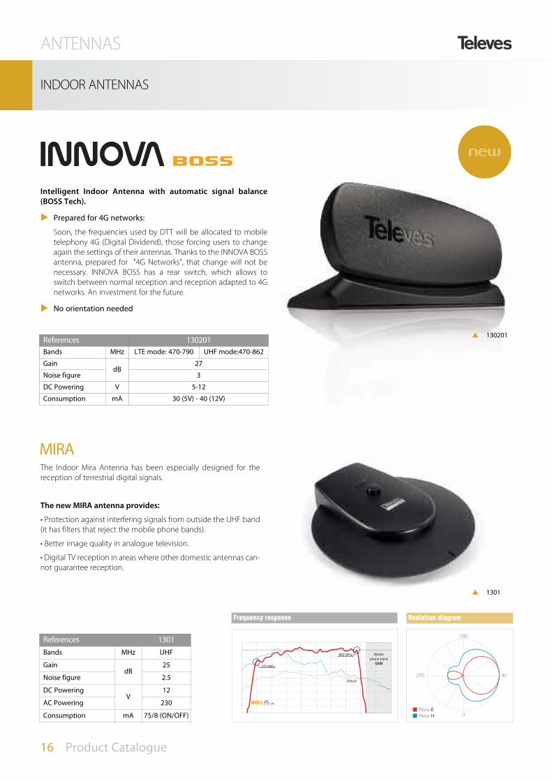
Intelligent Indoor Antenna with automatic signal balance(BOSS Tech).
u Prepared for 4G networks:
Soon, the frequencies used by DTT will be allocated to mobiletelephony 4G (Digital Dividend), those forcing users to changeagain the settings of their antennas. Thanks to the INNOVA BOSSantenna, prepared for "4G Networks”, that change will not benecessary. INNOVA BOSS has a rear switch, which allows toswitch between normal reception and reception adapted to 4Gnetworks. An investment for the future.
u No orientation needed
INDOOR ANTENNAS
p 130201
The Indoor Mira Antenna has been especially designed for thereception of terrestrial digital signals.
The new MIRA antenna provides:
• Protection against interfering signals from outside the UHF band(it has filters that reject the mobile phone bands).
• Better image quality in analogue television.
• Digital TV reception in areas where other domestic antennas can-not guarantee reception.
MIRA
References 1301Bands MHz UHF
GaindB
25
Noise figure 2.5
DC Powering V
12
AC Powering 230
Consumption mA 75/8 (ON/OFF)
References 130201Bands MHz LTE mode: 470-790 UHF mode:470-862
GaindB
27
Noise figure 3
DC Powering V 5-12
Consumption mA 30 (5V) - 40 (12V)
Radiation diagram
270 90
180
0Plane EPlane H-5
0
5
10
15
20
25
30
35
40
G (dB)
470 MHz
862 MHz Mobilephone band
Others
45
GSM
Frequency response
p 1301
new

Satellite dishes made of steel and finished with polyester paint. Wide range of LNBs to cover any
possible solution.
SATELLITE

18 Product Catalogue

OFF-SET
DISHES AL HQ
7902 850 1 orange
790201 850 1 white
7903 950 1 orange
790301 950 1 white
DISHES AL
9306 650 1 orange
930601 650 1 white
930611 650 10 white
930621 650 100 white
DISHES FE
790011 600 10 white
790020 600 100 orange
790021 600 100 white
7535 650 1 orange
753501 650 1 white
753510 650 10 orange
753511 650 10 white
753520 650 100 orange
753521 650 100 white
7901 800 1 orange
790101 800 1 white
790110 800 5 orange
790111 800 5 white
790120 800 100 orange
790121 800 100 white
7534 1000 1 orange
753401 1000 1 white
753410 1000 5 orange
753411 1000 5 white
753420 1000 100 orange
753421 1000 100 white
753401 1000 1 white
7572 1100 1 orange
757201 1100 1 white
7575 1300 10 white
Ref. DeSCRIPTION PRODUCT RANGE
Wind pressure N/m2 800 1100Wind speed Km/h 130 150
SATELLITE
19 Product Catalogue
SATELLITE DISHES
Dish size (mm) 650 800 900 1000 1100
Gain at 11.7 GHz dB 36.0 39.0 39.5 40.5 41.5
Bandwidth GHz 10.7 a 12.75
OFFSET angle (º) 26.5 25 24
Thickness mm 1(AL); 0.65 (FE) 0.7 1.6 0.8 1
Elevation angle (º) 10···60
Wind load800
N/m2345.6 499.2 706.2 739.2 912
1100 475.2 686.4 980.4 1016.4 1254
The new QSD line of Televes satellitedishes are launched to market aftercareful and strict product require-ments that guarantee maximumperformance against corrosion,resistance to wind and ease of insta-llation.
Aluminium dish reflector, withdiecast Zamak LNB holder.
Folding arm for fast and easymounting
Pre-mounted support and arm
Robust back support. Hot galva-nized
Hidden cable routing systemwith folding tabs
Inox screws
TÜV Approved
p 7902
p 7901

SATELLITE
20 Product Catalogue
LNB AND SUPPORTS
Low noise figure and high gain LNBs.
7475 Universal single orange
747701 Universal QUATTRO orange
747702 Universal QUATTRO grey
747802 Universal TWIN orange
761001 Universal QUAD orange
7613 Universal OCTO grey
7611 Monoblock (2 LNB) offset dishes (80 cm) grey
Ref. DeSCRIPTION PRODUCT RANGE
LNB
Zinc plated surface as well as an special Reactive Sealing Treatmentto increase its resistance against corrosion.
Supports
7390 “Y” wall/ground support 294x294 Ø45X1,5
7393 “L” wall support offset 284x194 Ø35X1,5
7349 “L” support 380x350 Ø45X1,5
7371 “L” wall support 500x450 Ø45X2
7576 “T” ground base 750x200 Ø60X2,9
7409 Embedded base for 7392/7576 (325 high)
Galvanized
719201 Universal wall/ground support 223x610 Ø60X1,5
719202 Universal wall/ground support 211x604 Ø45X1,5
719203 Universal wall/ground support 287x440 Ø40X1,25
Ref. DeSCRIPTION (length, height, diameter)
PRODUCT RANGE
References 7475 747701/02 747802 761001 7611 7613 Input frequency GHz 10.7-12.75Output frequency MHz 950/1950 - 1100/2150 No. of outputs 1 (H/V) 4 (Ha-Va-Hb-Vb) 2 (H/V - H/V) 4 (H/V-H/V-H/V-H/V) 1 (H/V) 8x (H/V- l/h)Gain
dB51 57 57 58 57 57
Noise figure 0.5 0.5 0.5 0.5 0.7Local oscillator GHz 9.75/10.6Powering Vdc 12···20Max. consumption mA 90 190 170 180 120 200 Operating temperature ºC -30···+60
p 7611p 7613
p 747701
p 7409p 7576p 7371
p 7349p 7393p 7390/719201
p 7475
p 761001p 747802

SATELLITE
21 Product Catalogue
FEEDHORNS AND SUPPORTS
Multisatellite
7508 For 800 mm offset antenna 6º
790901 QSD Multisatellite 6º
790902 LNB support for QSD dishes
Ref. DeSCRIPTION PRODUCT RANGE
A Televés patent that allows the user to receivesignals from various satellites located in diffe-rent orbital positions with a single dish.
SAT 2(Astra 19,2 E)
SAT 1(Eutelsat 13 E)
6,2ºBeam 2
Beam 1A1
A2
p 7508
p 790901
p 790902
Accessories
References 7450
Max. input voltage Vdc 24
Max. current A 1
Frequency margin MHz 10-2150
Through lossesdB
0.5
Return losses >10
Current injector for LNB powering.
p 7450
new

22 Product Catalogue

The mechanical accessory line is treated with Reactive Sealing Coating, improving the zinc
cover process already applied to every product by adding an extra protection against oxidation.
MECHANICAL ACCESSORIES

24 Product Catalogue

MECHANICAL ACCESSORIES
25 Product Catalogue
MECHANICAL ACCESSORIES
Masts
3008 35 mm 2,5 m
3009 40 mm 2,5 m
3010 45 mm 3 m
3072 40 mm 3 m
3040 40 mm 1,5 m
3041 40 mm 2 m
3042 35 mm 2,5 m
2407 35 mm 1,5 m
3075 45 mm 3 m red
Ref. DeSCRIPTION PRODUCT RANGE
Mast clamps
2117 Window mast clamp
For chimney
2414 Tubular
2415 Reinforced tubular
For bolting
2409 L-Shape
2401 300 mm “L”
2403 “V” bracket
2404 500 mm “U”
2083 Retractable wall mount
For embedding
2405 350 mm “I”
2406 500 mm “U” reinforced
2410 250 mm “I” reinforced
Ref. DeSCRIPTION PRODUCT RANGE
Supports and clamps for masts
(1) Red
3000 x 45Ø Ref. 3010, 3075
3000 x 40Ø Ref. 3072
2500 x 40Ø Ref. 3009
2500 x 35Ø Ref. 3042
2500 x 35Ø Ref. 3008
1450x 35Ø Ref. 2407
2000x 40Ø Ref. 3041
1500x 40Ø Ref. 3040
Referencias 3008 3009 3010 3072 3040 3041 3042 2407 3075(1)
Length mm
2500 3000 1500 200 2500 1450 3000Diameter 35 40 45 40 40 40 35 35 45Thickness 1,5 2 2 2 1,25 1,25 1 1,5 2Bending moment Nxm 299,70 508,75 656,75 508,75 170 170 207,20 299,70 656,75
p 2117
p 2409
p 2401 p 2403 p 2404
p 2405p 2083 p 2406 p 2410
p 2414 p 2415
new

MECHANICAL ACCESSORIES
26 Product Catalogue
MECHANICAL ACCESSORIES
Accessories
Cables
Cable clips
2000 Opened
2011 Closed
Accessories
2047 Jaw clamp for masts up Ø45
2408 Saddle & clamp
2412 Corner piece
2413 Mast clamp
4361 Guy wire mounting kit
Ref. DeSCRIPTION PRODUCT RANGE
Steel cables
2043 2 mm
2044 2,5 mm
3034 4 mm
3059 5 mm
Ref. DeSCRIPTION PRODUCT RANGE
Ø30x1
200
130 586 300
400 385
40402
15x30x1
100
100
30
30
4 500
4040
9
30
2,5
250
Ref. 2415
Ref. 2404
Ref. 2410Ref. 2117
30
350
6
500
50
40
20
40
Ref. 2405 Ref. 2406
128
128
30
Ref. 2409
90
90 3 300
30
30
Ref. 2401
255
30
120
250
260
245
315
415
Ø30x1
345
Ref. 2403
Ref. 2414
p 3034
p 4361p 2047p 2413
p 2412p 2408p 2000/2011

(*) Spanish abbreviation for Reactive Sealing Treatment
MECHANICAL ACCESSORIES
27 Product Catalogue
MECHANICAL COMPLEMENTS
Towers
180 SE RPR (*)
3014 Upper section 1,25 m
3015 Upper section w/ring 2,5 m
3017 Middle section 2,5 m
180 RPR
3021 Upper section 0,6 m
3032 Upper section 3 m
3031 Middle section 3 m
3037 Lower section 3 m
Ref. DeSCRIPTION PRODUCT RANGE
360 RPR
3085 Upper section
3086 Lower section
3087 Middle section
360 Colour
308601 Lower section red
308701 Middle section red
308702 Middle section white
308501 Upper section red
RPRReactive Covering Coat
Red colourLacquered in oven with electros-
tactic powder of Polyester
White colourLacquered in oven with electros-
tactic powder of Polyester
Made of zinced steel and bi-chrome coating, are supplied intwo types of finishing (RPR or poliester painting). They can beinstalled at heights from 1 to 50,5 m.
Depending on the model, they implement turned or pluggedraccors (SE finishing) for its union.
Installation types (Mod. 180 y 360)Section by section
Fixing the lower section to the base in the proper vertical posi-tion, and then mounting the consecutive intermediate sec-tions, which will be fixed with the corresponding guy-wire; theassembly is carried out by climbing the already placed sectionsand raising subsequently the section to be placed, using for itthe adequate elevating tools.
The climbing has to be made with the appropiate safety con-ditions (safety-belt, anchoring, etc.); there won’t be more thantwo sections without shoring up. In case of coinciding two sec-tions without guy-wire, auxiliary guy-wire will be used for thebracing of the sections during the set-up. The tower will bebalanced adjusting the tension of the guy-wire and the usingof proper balance-appliances.
Complete tower
First assembling the tower over the ground and raising it, oncemounted, by means of a crane.
This system can be used only with towers of heights lower than18 meters in the model 180 and heights lower than 26 metersin the model 360.
Safety
If the installation of the tower is made on the roof, flat roof orother place of a building, the installer will take the necessarymeasures according to the indications of the architect respon-sible of the building, in order to know the mechanical resistan-ce of these zones.
Types of finishing
References 180 SE 180 360Main stainless steel tubes
mm20x1,5 20x2 30x2
Transversal stainless steel rods 6 6 10Max. height with mast 3m m 7,5 20,5 50,5
Tower
Point ofAnchoring

MECHANICAL ACCESSORIES
28 Product Catalogue
Main characteristics:
Model 450
• Two new types of sections are available: reinforced sections (thickerlattice and walltube) and slight sections.
• The reinforced sections will be the ones situated in the lower part ofthe tower and the light ones will be installed in the higher part. Withthis is possible to mount higher towers (up to 81m).
• Ideal to assemble towers of a height of 57 till 81m.
Model 450/550
These sections incorporate some improvements with regard to theprevious range, consisting in:
• New raccor: detachable element that makes the anticorrosive treat-ment of the whole section easier, getting a significant increase of thedurability of the tower.
• New lattice: it increases the mechanical resistance to the torsionand it reduces its weight.
• New distribution of footing:
- Less number of footing for guy-wire.
- Reduction of distance needed between the footing for guy-wire and the tower.
450 (Sections of 3m.)
3130 Reinforced low-end Red
3131 Intermediate Red
313101 Intermediate White
3132 Reinforced Intermediate Red
313201 Reinforced Intermediate White
3133 Upper Red
References 450
Main stainless steel tubesmm
normal reinforced
38x2,6 40x3
Transversal stainless steel rods 10 12
Max. height with mast 3m m 81
Towers. Model 450/550 (Recommended for special installations)
3133
Ref. DeSCRIPTION PRODUCT RANGE
3130313101
313201
3131
3132
Raccor Improvements implemented
Racor presentation.
Disassembly for the insertion of the thread.
Insertion of the thread.
Connection of the sections.
Final appearence of the coupled sections.
1
2
3
4
5
MECHANICAL COMPLEMENTS
RPRReactive Covering Coat
Red colourLacquered in oven with electros-
tactic powder of Polyester
White colourLacquered in oven with electros-
tactic powder of Polyester
Types of finishing

MECHANICAL ACCESSORIES
29 Product Catalogue
MECHANICAL COMPLEMENTS
Main characteristics:
• Specially designed to assemble towers of a height up to 120m
600 Colour (Tramos de 3m.)
3101 Standard section white
3102 Standard section red
3103 Guy wire section white
3104 Guy wire section red
3102
Standard section Guy wire section Top mast holder
3101 3104
3105
3103
Towers. Model 600
References 600Main stainless steel tubes
mm70x4
Transversal stainless steel rods 20
Max. height with mast 3m m 104
Specially designed to achieveheights from 81 to 104 meters.
550 (Sections of 3m.)
313901 Lower section Red
3140 Middle section Red
314001 Middle section White
3141 Transition section 550 to 450 Red
Ref. DeSCRIPTION PRODUCT RANGE
Ref. DeSCRIPTION PRODUCT RANGE
Towers. Model 550new
Red colourLacquered in oven with electros-
tatic powder of Polyester
White colourLacquered in oven with electros-
tatic powder of Polyester
Types of finish
RPRReactive Covering Coat
Red colourLacquered in oven with electros-
tactic powder of Polyester
White colourLacquered in oven with electros-
tactic powder of Polyester
Types of finishing313901 31413140013140
References 550Main stainless steel tubes
mm60x4
Transversal stainless steel rods 14Max. height with mast 3m m 122

MECHANICAL ACCESSORIES
30 Product Catalogue
MECHANICAL COMPLEMENTS
Main characteristics:The new tower Q1500 allows us to reach the 14.5 m high with acompletely new design made of stainless steel of high purity. Thealloy INOX316 remove iron impurities, preventing oxidation andoffering more long-term security with less maintenance.
The whole design of the tower, the structure and the anchors ofthe guy wires have relied on Navy technology. This new configu-ration allows us to install a tower at 14.5 m occupying only an areaof 1.5 m radius. Save 401m2 of yard to a conventional tower.
Q1500
• Made of AISI 316 Stainless Naval. Ensures the structural characteris-tics of the tower along the time.
• Virtually unlimited duration.
• Greater torsional strength and stiffness.
• Easier handling and assembly.
• New system of couplings that facilitate the connection between
the sections.
• Complete kit for installation, with all its accessories.
3049 KIT Tower Q1500 stainless steel 14,5m
Towers. Q1500 (Recommended for urban zones and densly populated areas)
Ref. DeSCRIPTION PRODUCT RANGE
Base section + guy wires anchoring Middle cross section Dimensioning of the winds

MECHANICAL ACCESSORIES
31 Product Catalogue
MECHANICAL COMPLEMENTS
180 SE
3019 Frame embedded base
3020 Solid base
180
3048 Pivoting base embedded
3038 Solid base
3029 Frame base embedded
360
3088 Pivoting base embedded
3089 360 self-suporting emb. base
450
3134 Pivoting base embedded
550
3142 Pivot Embedded base 550
3143 Fixed Base 550
600
3106 Pivot bearing support
3107 Guy wire base
3108 Tower base bracketry
3109 Guy wire bracketry
Ref. DeSCRIPTION PRODUCT RANGE
3034 Guy wire Ø 4 mm
3059 Guy wire Ø 5 mm
3058 Guy wire ring (360)
3144 Guy wire ring (450)
3105 Top mast holder (600)
Ref. DeSCRIPTION PRODUCT RANGE
Tower bases
Tower accessories
600 series
600 series
3105
3144
3059
3058
p 3134
p 3089p 3088
p 3143p 3142
p 3048
p 3038
p 3019
p 3029
p 3020
p 3108
p 3109
p 3107
p 3106

32 Product Catalogue

Our range of electronic products includes everything the installer may need. Innovative designs
to make the job easier and using the most advanced technology to fulfill the Guidelines of the
CE standards.
ELECTRONICS

34 Product Catalogue

Band mixers made of ABS plastic for outdoor use.
New easy F connectors.
Mast mixers
Terrestrial
4040 BI-FM/BIII-DAB/UHF
4041 VHF-UHF1/UHF2
4334 4041 blister
Ref. DeSCRIPTION PRODUCT RANGE
References 4040 4041
Mixed bands BI-FM47-108
BIII-DAB174-254
UHF470-862
VHF47-254
UHF1470-862
UHF2470-862
Through losses
dB
1 typ. 1 typ. 1 typ. 5 typ.
Return losses 10
Rejection bet. inputs >20 >40 (VHF-UHF)>18 (UHF1-UHF2)
Max. DC bypass mA - 100 - 100 -
Protection index IP 23
UHF
VHF
FM
Ref. 4040
T Y P I C A L A P P L I C A T I O N
D E T A I L O F T H E C O N N E C T I O N E A S Y F
ELECTRONICS
35 Product Catalogue
MAST
p 4040

ELECTRONICS
36 Product Catalogue
MAST
Mast amplifiers
Ref. DeSCRIPTION PRODUCT RANGE
Broadband amplifiers made of ABS plastic for outdoor use.
Easy F connector gives the advantages of both F connector and sad-dle & clamp.
5356 1in/1out BI-BIII-FM-UHF
5357 3in/1out BI-BIII/FM/UHF
535802 4in/1out BI-BIII/FM/UHF1-UHF2
5359 5in/1out FM/BI-BIII/UHF/UHF1/UHF2
536001 3in/1out BI-BIII-DAB/UHF1/UHF2
5370 3in/1out BIII-DAB/UHF1/UHF2
5377 3in/1out BIII-DAB/UHF
Kits
5688 5356 +PSU 5795
5698 5358 +PSU 5795
References 5356 5357 535802 5359
Inputs BI-BIII-DAB-FM-UHF BI/BIII FM UHF BI/BIII FM UHF1UHF2 FM BI/BIII UHF UHF1 UHF2
Frequency range MHz 47-68175-254 88-108 470-862 47-68
175-254 88-108 470-862 47-68175-254 88-108 470-862 88-108 47-68
175-254 470-862 *Note
Gain
dB
25/30 15 41 25/30 15 41 25/30 15 38 15 30 40 38
Gain regulation 20 15 15 20 15 15 20 15 20 15
Noise figure 4 7.5 4 7 8
Output level dBµV 112 114 112 114 112 114 112 114
DC bypass mA 40 automatic - 40 - 40 - 40
Input rejection dB - 18 18
Powering Vdc 24
Consumption mA 70
Protection index IP 23
(1) According crossover channel: Higher crossover channel: 55 / Lower crossover channel: 30
References 536001 5370 5377
Inputs BI-BIII-DAB UHF1 UHF2 BIII-DAB UHF1 UHF2 BIII-DAB UHF
Frequency range MHz 47-68175-254 470-862 175-254 470-862 175-254 470-862
Gain
dB
23/27 27 27 18 21 21 20 26
Gain regulation 20 15 15 13 13 15 15
Noise figure 7 8 8,5 7,5 6,5 7,5
Output level dBµV 111 114 111 114 111 114
DC bypass mA 40 - 40 40 - 40 40
Powering Vdc 12
Consumption mA 100
Protection index IP 23
1) Crossover channels, Min: 28, Max: 55
p 5357

5354 2in/4out U/Vmix-IF mix 4out
5350 3in/1out U/Vmix-IF mix
5351 4in/1out BI/BIII-FM-U-IF mix
5352 4in/1out U-U-Vmix-IF mix
Kits
5696 5351 +PSU 5795
5697 5352 +PSU 5795
4386 5350 +PSU 5796 (blister)
4388 5351 +PSU 5796 (blister)
5678 535101(black) +PSU 5796
Mast Amplifiers. IF Mix range
Ref. DeSCRIPTION PRODUCT RANGE Broadband amplifiers in a housing
made of ABS plastic for outdooruse.
New fast F connector gives theadvantages of both F connectorand saddle & clamp.
Capable of mixing SAT signals.
References 5351 5352
Inputs BI/BIII FM UHF IF VHF UHF1 UHF2 IF
Frequency range MHz 47···68175···254 88···108 470···862 950···2150 47···254 470···862 950···2150
GaindB
18 18 29 -2 -1 27 -2
Gain regulation 15 20 15 - - 15 -
Output levelDIN 45004-B dBµV 103 - - 103 -
Noise figure dB 4.5 2.5 - - 6.5 -
DC bypass mA - 350 - 40 - 350
Powering Vdc 12···24Consumption mA 40
Connection type Easy-F
(1) Please specify channel when ordering
ELECTRONICS
37 Product Catalogue
MAST
Referencias 5354 5350
Inputs VHF/UHF FI VHF UHF FI
Frequency range MHz 47···254 470···862 950···2200 47···254 470···862 950···2150
Gain dB
- 9 20 - 12 - 1.5 29 - 2
Gain regulation - 15 - - 15 -
Output levelDIN 45004-B dBµV - 93 - - 103 -
Noise figure dB - 2.5 - - 2.5 -
DC bypass mA - 40 350 - - 350
Powering Vdc 12···24
Consumption mA 40
Protection index IP 23

ELECTRONICS
38 Product Catalogue
DOMESTIC
Domestic amplifiers
Power supply units
550101 130 mA 12 V F connectors
5504 130 mA 24 V F connectors
Ref. DeSCRIPTION PRODUCT RANGE
References 550101 5504 Bandwidth MHz 47-860 47-860
Mains voltage ACV
230 230
Mains voltage 12 24
Output current mA 130 130
Connection type F F
Dimensions mm 145x45x35
Digi amplifiers
5517 Dig-Setback 2 In-4 Out-DC
5514 Digi Ampl 4 Out DC Pass
Ref. DeSCRIPTION PRODUCT RANGE
References 5517 5514
Inputs no. 2 1
Outputs O1-O4 O1-O2-O3-O4
Forward path
Bandwidth MHz 47···232 / 470···860 47··· 862
GaindB
16 5
VHF/UHF variable gain 12 -
Output levelDIN45004B
VHFdBµV
108>94
UHF 105
Rejection between outputsdB
>25 >25
Noise figure (typ.) 5.5 3.5
Return path
Bandwidth MHz 5···30
Gain dB 6 8
Output level dBµV 110 97
Noise figure dB 16 12
Powering
Input voltage V/mA 230 Vac jack:12Vdc/40mA
I/P port: 9Vdc/30mAO/P ports: 8Vdc/10mA
Output line voltage Vdc 11 (each O/P connector) -
Max. output line current mA 10 -
p 5504

ELECTRONICS
39 Product Catalogue
DOMESTIC
Ref. 5530
Ref. 7452
T Y P I C A L A P P L I C A T I O N
MATV
5527 IEC 1 In-1 Out
5528 IEC 1 In-2 Out + TV
5529 IEC 1 In- 4 Out + TV
5457 IEC 1 In- 2 Out + TV, DC 100 mA
5519 F 1 In-1 Out split-band
5522 F 1 In-2 Out + TV
5523 F 1 In-4 Out + TV
5531 F 1 In-6 Out
5530 IF+MATV 1 In-2 Out TV
553201 1 In-2 Out + DC
Ref. DeSCRIPTION PRODUCT RANGE
CATV
5520 1 In-2 Out + TV Passive Return
5526 1 In-2 Out + TV Active Return
5525 1 In-2 Out + TV Var. Equaliser
5533 1 In-1 Out Passive Return 5-30 MHz
5535 1 In-1 Out Passive Return 5-30 MHz
SAT IF
5530 IF+MATV 1 In-2 Out TV
(*) DIN45004B (**) 2 tones @ -35dB
References 5527 5528 5529 5522 5523 5531 5519 5457 553201
Bandwidth MHz 47...862 47...862 47-320470-862 47-862 47-862
GainO1...O6
dB25 20 16 20 16 16 17 / 27 20 20
TV - 14 13 14 13 - -3 / 7 14 -Variable gain
dBµV 12
Output level DIN45004B 112 106 102 106 102 103 105 106 110Rejection between outputs
dB - >20 >25 >20 >25 >25 >25 >25 -
Noise figure (typ.) 5 4 5Input line powering V - 12 12Input line Max. Current mA - 100 100Connectors type IEC F IEC F
References 5533 5535 5530 5520 5526 5525Inputs
no.1
Outputs 1 3 (O1-O2-TV)Forward path
Bandwidth MATV MHz 47...862 47...862 47...862 87,5...862 87,5...862SAT IF MHz - 950...2400 -
Gain MATV
O1-O2dB
24 3418
20 18
TV - 13 12
SAT IF dB - 19 -
Output levelDIN45004B
MATVO1-O2
dBµV 112
105*107 > 106
TV - 101SAT IF dBµV - 110** -
Variable gain
dB
18 8 12 18Variable equaliser 18 - - 18
Rejection between outputs - >18 >20
Noise figure(typ.)
MATV 7 5.5 5 5.5 6
SAT IF - <4 - - -
Return pathBandwidth MHz 5...30 5...30 5...30 5...65 5...65 Gain dB -1 -1 -9 -7 9 - 7
Powering
Mains voltage (jack) Vac 230 In-Out DC bypass mA - 300 -
Low
consumption

ELECTRONICS
40 Product Catalogue
References 5795 5796Frequency Margin MHz 5-862 5-2500
Output voltageV
24 12
Mains voltage 196-264
Max. Output currentmA
130 220
Min. Output current 30
Max. temp. operation 45º C
Protection level IP 20
Consumption W 4,4 3,7
newPicokom Series
T Y P I C A L A P P L I C A T I O NT Y P I C A L A P P L I C A T I O N
High efficiency switched-mode power supply unit
Ultra compact design
40 % lower power consumption
5795 130 mA 24 Vdc Picokom
5796 220 mA 12 Vdc Picokom FI-MIX
Ref. DeSCRIPTION PRODUCT RANGE
DOMESTIC
p 5795

ELECTRONICS
41 Product Catalogue
5605 Domestic amplifier Picokom 2 outputs
560502 5605 in Blister
560601 Domestic amplifier RF+SAT
Ref. DeSCRIPTION PRODUCT RANGE
References 5605 560601
Frequency range MATV 47-400 470-862 47-862
Frequency range IF - 950-2150
Gain VHF/UHF
dB
12/20 15/15
Gain IF - 23
AGC Margin (only MATV) 20 12
Output level VHF/UHFDIN45004B dBµV 105 97
IMD3 (2ch@-60 dB) VHF/UHF
dBµV
97/102 94
IMD2 (2ch@-60 dB) VHF/UHF 87/92 87
Output level IFDIN45004B - 106
Returnt losses I/O dB 10 10
Noise figure VHF/ UHF dB 5/4,5 7
Noise figure IF dB - 9
Mains voltage Vac 196-264
Max power consumption preamplifiers 12Vdc. mA 150 160
OUT-IN DC bypass mA - 300
Total max. consumption. W 2,5 2,5
new
Picokom is a new amplifier design of splitband amplificationVHF/UHF with a built-in switched power supply unit.
1 Input and 2 outputs
The amplification is carried out in two independent stages, one forUHF and the other for VHF.
The Amplifier is able to reach 100 dBuV in VHF and 105 dBuV inUHF.
Automatic Control Gain (AGC)
EasyF connectors give the advantages of both F connector andsaddle & clamp.
Ref. 5605
+ 12 DC
+ 12 DC
SWITCHON/OFF+12Vdc
T Y P I C A L A P P L I C A T I O N
Picokom Series
DOMESTIC
p 5605

ELECTRONICS
42 Product Catalogue
TERRESTRIAL/SATELLITE TV
Line amplifiers
4006 UHF 13 dB
7485 IF 20 dB
Ref. DeSCRIPTION PRODUCT RANGE
Amplifier powered bymeans of coaxial cable toadapt the input level inthe headend equipment.
The ref. 7485 also allowsthe powering bypasscurrent for LNB conversor.
Notch filters
4162 2 ch. 2 adjustments
4007 1 ch. F connector
4163 ABS plastic case
Ref. DeSCRIPTION PRODUCT RANGE
Attenuators
5165 Adjustable 20 dB
4005 0-20 dB adjustable, DC bypass
Ref. DeSCRIPTION PRODUCT RANGE
References 4006 7485MATVFrequency range MHz 470-862Gain dB 13 - 2,5
Output levelDIN 45004 B dBµV 98 -
Noise figure dB < 4.5 -IFFrequency range MHz - 950-2150 Gain dB - 20
Output levelDIN VDE0855/12 dBµV - 112,5
Noise figure dB - < 5,5
GeneralConsumption
mA23 (24 Vdc) 60 (12···18Vdc)
Max. bypass current - 500 (OUT-IN)
References 4162 4007Adjustments 2 1Nº of channels 1 2 1
Insertion losses
UHF
dB
<1 <1BIII <2 -FM <10 -BI <15 -
Pv*Attenuation
Pv n >35 15-20 >15
Pv n±1 - <3 <5
Pv n±2 <3 - <1
Connectors IEC FDC bypass Yes
(*) Video carriern: Tuned channel
References 5165 4005Range adjustable
Attenuation margin dB 0-20
Band MHz 47-860 5-2200
DC bypass Yes
p 4006
p 7485
p 4162
p 4007
p 4005

ELECTRONICS
43 Product Catalogue
TERRESTRIAL/SATELLITE TV
C3 with modular Return Path
534602 Microkom 20/20 5-65 MHz
534702 Microkom 24/20 5-65 MHz
536602 Microkom 30/25 5-65 MHz
536702 Microkom 35/28 5-65 MHz
C3 return Path Module
455320 Return Path 5-65 Mhz 20 dB
455325 Return Path 5-65 Mhz 25 dB
455328 Return Path 5-65 Mhz 28 dB
C4 with Fixed Return Path
534202 Microkom 20/20 dB 5-65 MHz
534302 Microkom 30/25 dB 5-65 MHz
534402 Microkom 35/28 dB 5-65 MHz
Ref. DeSCRIPTION PRODUCT RANGE
MicroKom series
References 534602 534702 536602 536702 534202 534302 534402
Forward path
Frequency range MHz 85 - 862
Gain dB
20 24 30 35 20 30 35
Noise figure 7,5
Vout DIN 45004B
dBµV
118
Vout EN 50083-3 IMD3 (2 ch, -60 dB) 100
Vout EN 50083-3 CTB, CSO, XMOD (42 ch, -60 dB) 100
Input Attenuator (2dB steps)
dB
0...18
Return Losses 12
Nominal value deviation ±1
Return path
Frequency range MHz 5 - 65
Gain
dB
20 20 25 28 20 25 28
Noise figure 6
Interstage equalizer (2 dB steps) 0/3/6
Return Losses 12
Vout DIN 45004BdBµV
118
Vout EN 50083-3 IMD3 (2 ch, -60 dB) 115
Input Attenuator (2dB steps)dB
18
Nominal value deviation ±1
GeneralMains voltage Watt 207-253 / 50-60
Power consumption Vac/Hz 5 5 5,5 6 5 5,5 6
Operating temperature ºC -10... + 45
Protection Index IP 20
Connnectors HF type F-Female
Dimensions mm/g 185x80x35 /400
new
Configuration by means of internal jumpers
Feature both system and cable equalisers
Input and Output -20 dB test connectors

ELECTRONICS
44 Product Catalogue
TERRESTRIAL/SATELLITE TV
IF
537302 1 input V-U
537201 2 inputs V/U (7+1 outs.)+R5-7MHz
5399 2 inputs V/U (switch DC bypass, interstage atten.)
531201 3 inputs FM/BIII-DAB/UHF
539201 4 inputs FM/BIII-DAB/UHF1/UHF2
539104 5 inputs FM/BIII-DAB/UHF/BV/BIV
539105 5 inputs FM/BIII-DAB/UHF/BV(590-862)/BIV(470-566)
Terrestrial
Minikom series - Splitband Amplification
Ref. DeSCRIPTION PRODUCT RANGE
5363 2 inputs IF / mixed MATV incudes a 22 KHz switch (0.6 ±1 Vpp)
5317 2 inputs IF1-MATV/IF2-MATV
5396 4 inputs (VHF/BIII/BI-FM/IF)
T Y P I C A L A P P L I C A T I O N
p 5317
References 5363 5317 5396Inputs IF/MATV IF1-MATV/IF2 UHF/BIII/BI-FM/IFOutputs IF-MATV IF1-MATV/IF2-MATV IF-MATVIF path Frequency range MHz 950-2150Attenuator
dB0-20 0-20 0-20
Equaliser 0-12 0-15 0-15Gain 35-45 35-40 35-42Output level DIN VDE 0855/12 dBµV 124 123 121Noise figure dB <9 10 14MATV path Frequency range MHz 47-862Attenuator dB - 0-15 -Equaliser - 0-20 -Gain -1.5 30-35 -Output level DIN 45004 B - 117 - Output level CSB/CSO/XMOD - 96 - Return path MHz - 5-30 passive - GeneralPowering voltage Vac 230 230 196-26422 KHz tone amplitude Vpp 0.6±1 - - Max. DC current for LNB mA 300 (13/17Vdc) - 500
References 537302 537201 5399 531201 539201 539104/539105*
Inputs UHF-VHF Return PathVHF-FM/UHF UHF/VHF FM/BIII-DAB/UHF FM/BIII-DAB/
UHF1/UHF2FM/BIII-DAB/UHF/BV/BIV
Frequency range MHz 47-454/470-862
5-7/47-230/470-862
47-232/470-862
88-108/174-400/470-862
88-108/174-400/470-862
88-108/174-400/470-862/614-862/470-590
Gain (high) dB
30/37 VHF 5(16 - 0+1)35/40
15/30/40 15/30/37 15/30/37/35/35
Gain (low) 20/27 UHF 15(27 - 0+1) 15/20/30 15/20/27 15/20/27/25/25Attenuation margin
dBµV
0-20 - 0-20/0-15 0-20 0-20 0-20Output level (DIN 45004B) High
114/116 88/101 (OUT+1)108 (Ret. Path) 115/117
114/114/117 114/114/117/117 114/114/117/117/116Output level (DIN 45004B) Low 112/112/116 112/112/116/116 112/112/116/116/115
Output level (IDM3)(2ch -60dB) High111/113 - -
111/111/114 111/111/114/114 111/111/114/114/113
Output level (IDM3)(2ch -60dB) Low 109/109/113 109/109/113/113 109/109/113/113/112
Noise figure HighdB 7 2,5 6/4
9/6/5 9/6,5/8/9/9 9/6,5/8/8
Noise figure Low 9/6,5/6,5 9/7/9,5/10,5/10,5 9/7/9,5/9,5
Total input DC Bypass mA 70@12Vdc 30 (UHF) 60@24Vdc 70@12Vdc (BIII-DAB, UHF)
70@12Vdc (BIII-DAB, UHF1) 70 @ 12Vdc (excep FM)
Mains voltage V 207-253
* Ref. 539105 BV(590-862)/BIV(470-566)

ELECTRONICS
45 Product Catalogue
TERRESTRIAL/SATELLITE TV
System accessories
References 5456Mains voltage
Vac FIC230±15
Output voltage 57
Max. output current A 5
Max. power consumption W 375
Frequency range MHz 5-860
Dimensions mm 278x217x100
5456 AC Outdoor power supply unit
Outdoor CATV
Ref. DeSCRIPTION PRODUCT RANGE
4513 Outdoor R5-65 MHz hybrid AC line powered
References 4513
Forward path
Frequency range MHz 85 - 862 Attenuator
dB
20 Cable equaliser 7,5 System equaliser 118
Gain 100
Max. output level (DIN 45004B)dBµV
100 Max. output level 0...182nd order distorsion
dB12
Noise figure ±1In-Out return lossesReturn pathFrequency range MHz 5 - 65Attenuator
dB
20Gain 6Flatness 0/3/6In-Out return losses 12GeneralPowering voltage V 207-253 / 50-60
Power consumption W 5 Protection Index IP 20

ELECTRONICS
46 Product Catalogue
TERRESTRIAL/SATELLITE TV
DT Kom
PUSH-PULL HEADEND AMPLIFIERS
5340 3 in/1 out - BI-FM/BIII/UHF
5341 5 in/1 out - BI-FM/BIII/BIV/BV/UHF
539105 5 inputs FM/BIII-DAB/UHF/BV(590-862)/BIV(470-566)
POWER-DOUBLING HEADEND AMPLIFIERS
4507 3 in/1 out - FM/VHF/UHF
4508 4 in/1 out - FM/VHF/UHF/UHF
4509 5 in/1 out - FM/VHF/BIV/BV/UHF
PUSH-PULL LINE AMPLIFIERS
5338 1 in/1 out - FP 47-862 MHz
5339 1 in/1 out - FP 47-862 MHz/RP 5-30 MHz
533901 1 in/1 out - FP 87-862 MHz/RP 5-65 MHz
5335 1 in/1 out - FP 47-862 MHz/RP 5-30 MHz + 1×IF 950-2150 MHz
533501 1 in/1 out - FP 47-862 MHz/RP 5-65 MHz + 1×IF 950-2150 MHz
POWER-DOUBLING LINE AMPLIFIERS
451201 1 in/1 out - FP 47-862 MHz/RP 5-65 MHz
451202 1in/1 out - FP 87-862 MHz/RP 5-30 MHz
5337 2 in/2 out - FP 47-862 MHz/RP 5-30 MHz+2×IF 950-21502 MHz
Ref. DeSCRIPTION PRODUCT RANGE
new
POWER DOUBLING RANGE
Up to 129 dBµV for both VHF & UHF Up to 120 dBµV for 2xIF amplifiers with input equaliser High/Low selectable gain Active/passive selectable return path
PUSH-PULL RANGE
Up to 120 dBµV for 2xIF amplifiers with input equaliser Active/passive selectable return channel High/Low selectable gain Line powered, switchable (just 5338)
User friendly design
Input signal detector
LED for each band
All controls accessible from outside
ELECTRONICS
47 Product Catalogue
TERRESTRIAL/SATELLITE TV
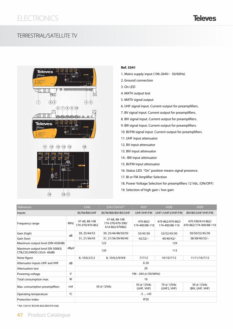
References 5340 5341/534101* 4507 4508 4509
Inputs BI,FM/BIII/UHF BI,FM/BIII/BIV/BV/UHF UHF/VHF/FM UHF1/UHF2/VHF/FM BIV/BV/UHF/VHF/FM
Frequency range MHz 47-68, 88-108174-370/470-862
47-68, 88-108174-370/470-590/614-862/470862
470-862/174-400/88-110
470-862/470-862/174-400/88-110
470-590/614-862/470-862/174-400/88-110
Gain (high) dB
39, 25/44/53 39, 25/44/48/50/50 55/45/30 52/52/45/30 50/50/52/45/30
Gain (low) 31, 21/36/43 31, 21/36/39/40/40 42/32/-- 40/40/42/- 38/38/40/32/--
Maximum output level (DIN 45004B)
dBµV
123 129
Maximum output level (EN 50083)CTB,CSO,XMOD (35ch -60dB) 120 113
Noise figure
dB
8, 10/6,5/5,5 8, 10/6,5/9/9/8 7/7/12 10/10/7/12 11/11/10/7/12
Attenuator inputs UHF and VHF 0-20
Attenuation test 20
Powering voltage V 196 - 264 @ (50/60Hz)
Total consumption max. W 16
Max. consumption preamplifiers mA 50 @ 12Vdc 50 @ 12Vdc (UHF, VHF)
70 @ 12Vdc (UHF2, VHF)
50 @ 12Vdc (BIV, UHF, VHF)
Operating temperature ºC -5 ... +45
Protection index IP20
2 31 4 5
6 7 8 9 10
11
19 18 17
12 13 14 15 16
Ref. 5341
1. Mains supply input (196-264V~ 50/60Hz)
2. Ground connection
3. On LED
4. MATV output test
5. MATV signal output
6. UHF signal input. Current output for preamplifiers.
7. BV signal input. Current output for preamplifiers.
8. BIV signal input. Current output for preamplifiers.
9. BIII signal input. Current output for preamplifiers.
10. BI/FM signal input. Current output for preamplifiers.
11. UHF input attenuator
12. BV input attenuator
13. BIV input attenuator
14.- BIII input attenuator
15. BI/FM input attenuator
16. Status LED. “On” position means signal presence.
17. BI or FM Amplifier Selection
18. Power Voltage Selection for preamplifiers 12 Vdc. (ON/OFF)
19. Selection of high gain / low gain
* Ref. 534101 BV(590-862)/BIV(470-566)

ELECTRONICS
48 Product Catalogue
TERRESTRIAL/SATELLITE TV
References 5338 5339/533901 5335/533501
Channels Main MATVReturn
Main MATVReturn
FIActive Passive Active Passive
Frequency range MHz 47-862 47-862 (ref.5339)87-862 (ref.533901)
5-30 (ref.5339)5-65 (ref.533901)
47-862 (ref.5335)87-862 (ref.533501)
5-30 (ref.5335)5-65 (ref.533501) 950-2150
Gain dB 41-53 (select.) 41-53 (select.) 20 -4 40-53 (select.) 20 -4 42
Maximum output level (DIN 45004B)
dBµV
123 122 115 - 124 115 - -
Maximum output level (EN 50083) 120 119 113 - 119 113 - 121(3)
Noise figure
dB
10 10 9 - 10 10 - 13
Return losses 10
Attenuator 0-18 0-18 - - 0-18 - - -
Equalizer 0-18 0-18 - - 0-18 - - 0-12
Powering voltage W 196 - 264 @ (50/60Hz)
Total consumption mA 130
Operating temperature ºC -5 . . . +45
Protection index IP20
(3) 2 Ch. -35 dB
TKOMP. U-V-IV-III/I-FM
Ref. 5341
P. max 9 W 230V ~ ±10% 50HzFuse: T1A L 250V
USO EXCLUSIVO EN INTERIORFOR INDOOR USE ONLY
¡¡¡ATENCIÓN!!!NO ABRIR. TENSIONES ELEVADAS DENTRO
¡¡¡WARNING!!!DO NOT OPEN. LIVE PARTS INSIDE
20 dB
UHF
OK - MATV
Test-20 dB MATV
On
20 dB20 dB20 dB20 dB
+24V (150 mA max)
+12V
FMBI
ONOFF
BV BIV BIII BI/FM
V-10 dB
0 dB
Pre-amplif.
(50mA)(50mA)(50mA)(50mA)(50mA)
T Y P I C A L A P P L I C A T I O N
UHF BV BIV
BIII
BI
Ref. 5341
Headend
FM

ELECTRONICS
49 Product Catalogue
TERRESTRIAL/SATELLITE TV
References 451201 / 451202 5337
Channels Main MATVReturn
Main MATVReturn
FI 1 / FI 2Active Passive Active Passive
Frequency range MHz 47-862 (ref.451202)87-862 (ref.451201)
5-30 (ref.451202)5-65 (ref.451201) 47-832 5-30 - 950-2150
Gain dB 40-53 (select.) 20 -3 34-47 (select.) 17 -5 42
Maximum output level (DIN 45004B)dBµV
129 116 - 123 116 - -
Maximum output level (EN 50083) 126 113 - 120 113 - 120(3)
Noise figure
dB
10 10 - 10 15 - 12
Return losses 10
Attenuator 0-20 - - 0-20 - - -
Equalizer 0-20 - - 0-20 - - 0-12
I/O Test attenuation 20
Powering voltage W 196 - 264 @ (50/60Hz)
Total consumption mA 150 70 @ 12Vdc (UHF2, VHF)
Operating temperature ºC -5 . . . +45
Protection index IP20
(3) 2 Ch. -35 dB
TKOMP. U-V-IV-III/I-FM
Ref. 5341
P. max 9 W230V ~ ±10% 50HzFuse: T1A L 250V
USO EXCLUSIVO EN INTERIORFOR INDOOR USE ONLY
¡¡¡ATENCIÓN!!!NO ABRIR. TENSIONES ELEVADAS DENTRO
¡¡¡WARNING!!!DO NOT OPEN. LIVE PARTS INSIDE
20 dB
UHF
OK - MATV
Test-20 dB MATV
On
20 dB20 dB20 dB20 dB
+24V (150 mA max)
+12V
FMBI
ONOFF
BV BIV BIII BI/FM
V-10 dB
0 dB
Pre-amplif.
(50mA)(50mA)(50mA)(50mA)(50mA)
I. max 150mA196-264V~ 50/60HzFuse: T1A L 250V
USO EXCLUSIVO EN INTERIORFOR INDOOR USE ONLY
¡¡¡ATENCIÓN!!!NO ABRIR. TENSIONES ELEVADAS DENTRO
¡¡¡WARNING!!!DO NOT OPEN. LIVE PARTS INSIDE
Test IN-20 dBMATV
10 dB 10 dB
C. Ret
OK - Return
OK - MATV20 dB20 dB
Test OUT-20 dB MATV
+10 dB
C. Ret
On
Ret.IN
Ret.OUT
MATV 20 dB
T Y P I C A L A P P L I C A T I O N
Ref. 5341
Ref. 5335
Ref. 533501
Headend

ELECTRONICS
50 Product Catalogue
TERRESTRIAL/SATELLITE TV
Avant Series
5328 Avant HD BI/III/DAB-FM-10 UHF-SAT
5329 Avant HD MATV 1 out
2168 PC programming Sw. + Accs.
7234 Universal Programming Unit
5750 Outdoor cabinet
Ref. DeSCRIPTION PRODUCT RANGE
References 5328/5329Inputs UHF 1 UHF 2 UHF3 FM BI/BIII/DAB VHF/UHF IF/SAT (5328 only)Frequency bands MHz 470-862 87-108 47-68/174-230 47-430 470-862 950-2150
Filters configuration
10 0 0 - - - - -9 0 1 - - - - -7 2 1 - - - - -6 3 1 - - - - -5 3 2 - - - - -
Nº channels per filter 0-5(2) - - - - -Gain
dBAutomatic 42···45
Gain regulation 0-20(1) 0-25 - OFF(1) - - 0-12 - OFF(2)
Optimum input margin dBµV 60-105 60-85 62-87 69-73 70-74 -Manual reg. gain
dB±9 (by single channel) ±9 ±9 - - -
Slope adjustment 0-9 - - - - 0-12(2)
Output leveldBµV
117(3) /121 111(3) /115 117(3)/121 123Regulation Output level 96-111 76-101 91-106 96-111 -Noise figure
dB9 tip 10 - 9
Rejection 20 (±16 MHz) 20 (±16 MHz) - 40 (862 MHz)
Input line powering (5) Vdc 24 - 24 - - 13/17 (22 kHz)
(Automatic) I max. (4) mA 60 - 60 - - 300Mains voltage Vac 230±15% - 50/60 HzConsumption w 30Protection index IP 20Dimensions mm 320x250x60(1) Automatic regulation / (2) Programmable / (3) The output level depends of the number of channels / (4) Available current / (5) ON - OFF - AUTO
System accessories
CONTROL MODEvia modem PC
up to 30
Copyconfiguration into handset1
Paste it to any unit2
Copy & Paste any configuration with the new Intelligent Handset
2 Easy steps
new

ELECTRONICS
51 Product Catalogue
TERRESTRIAL/SATELLITE TV
T Y P I C A L A P P L I C A T I O N
Avant HD configuration
Avant HD adjustement result

ELECTRONICS
52 Product Catalogue
TERRESTRIAL/SATELLITE TV
Avant 3
REF. DESCRIPTION
PRODUCT RANGE
Accesories
Main features
5 UHF filters and 1 VHF filter
2 UHF inputs with two possible filter assig-ments (2-3 or 5-0); each filter can cluster upto 7 channels.
VHF input that can cluster up to 4 channels(7-28 MHz) (only 5326)
Input loopthru to mix the output of anotherAVANT3
Broadband output to another AVANT3
Split-band amplification
FM/BI input
Reference 5326 /5327
Inputs UHF 1 UHF 2 FM/BI BIII (ref. 5326)
VHF(ref. 5327) IN/MIX
Bandwidth MHzCCIR
Ch. 21-Ch. 6947-68
87-108
CCIRCh. 5-Ch. 12
Ch. S11-Ch. S20
47-406/470-862
174-300470-862
Number of filters/output 2/5 3/0 - 1 - -
Number of channels/filter 1-5(B.IV) /1-7(B.V) - 1-4 - -
General attenuationdB
0-20
Filter attenuation 0-15 - 0-15 - -
Input level
dBµV
60-80 65-90 65-90 - -
Output level 117 - 115 113/116 -
Output level IMD3 114 - 112 110/113 -
RejectiondB
20 (±16 MHz) 20 (±16 MHz) 20 (±8 MHz) - -
Noise figure 9 typ / 7 typ 9 typ / 7 typ -
Input powering (12 dB)Vac
50 mA 50 mA - 50 mA - -
Powering voltage 230±20% - 50/60 Hz
5326 Avant 3
5327 Avant 3 (Broadband VHF)
532701 Avant 3 XXXXXXX
7234 Universal Programming Unit
Out
FM
BIII-DAB
UHF1
UHF2
p 5326
p 7234

ELECTRONICS
53 Product Catalogue
T03 HEADEND EQUIPMENT
T12. Single Channel Amplification
Ref. DeSCRIPTION PRODUCT RANGE
References 508112 508212 508312 508712 509912 508812 508912 508612 509812 508012
fwfi fo fw MHz 47-88 87,5-108 174-230 104-174 195-232 230-300 302-470 470-862 950-2150
BW MHz 7 - 7 7 37 7 8 8→56 8 950-2150
G
dB
50 35 45 58 45 58 58 50 55 35→50
35 35 35 35 35 35 35 30 30 20
EQ - - - - - - - - - 0→12
VoutA (dBµV) 123* 114* 123* 125* - 124* 125* 125→111* 125* 124*
B (dBµV) - - - - 114*** - - 118→102* 118* 124*
I mA 100 400
I Vdc 24 13/17
KHz - 0/22
Ic mA 70 95 130
P dB <1 <3 <3 <1 <3 <1 <1 <3 <2 -3
Rn+1
dB
- - - - - - - >3 >18 -
Rn+2 >40 - >30 >30 >20 >25 >30 >15 >50 -
Rn+3 - - - - - - - >20 - -
Noise figure NF dB <9 <11 <12,5
p 508612
Amplifiers
508112 T12 Single Channel Amplifier BI 47...88MHz G 50dB Vo 123dBµV
508212 T12 Single Channel Amplifier FM 88..108MHz G 35dB Vo 114dBµV
508712 T12 Single Channel Amplifier S-Low Band 104...174MHz G 58dB Vo 125dBµV
508312 T12 Single Channel Amplifier BIII 174...230MHz G 45dB Vo 123dBµV
509912 T12 Single Channel Amplifier DAB 195..232MHz G45dB Vo114dBµV
508812 T12 Single Channel Amplifier S-High Band 230...300MHz G 58dB Vo 124dBµV
508912 T12 Single Channel Amplifier HyperBand 302...470MHz G 58dB Vo 125dBµV
508612 T12 Single/Multi Channel Amplifier UHF DTT 470...862MHz G 50dB Vo 125dBµV (Up to 7 Channel)
509812 T12 Single Channel Amplifier UHF High Selectivity 470...862MHz G 55dB Vo 125dBµV
508012 T12 Amplifier SAT 950...2150MHz G 35...50dB Vo 124dBµV
549812 T12 Switched-mode Power Supply Unit 60W 24V-2.5A
new
(*): EN 50083-5; (**): DIN VDE0855/12; (***): di= 50 dB (2 ch. 4 MHz)

ELECTRONICS
54 Product Catalogue
T03 HEADEND EQUIPMENT
T03. Single Channel Amplification
References 5080
Inputs/outputs 2-1
SAT IF
Frequency range MHz 950-2150
Gain
dB
35···50
Equaliser 0-12
Attenuator 0-20
Output levelDIN VDE0855/12 dBµV 124
Noise figure dB <12.5
MATV
Frequency range MHz 47-862
Through losses dB 1.5
General
Consumption (24 Vdc)mA
130
LNB Power supply 400
Dimensions mm 35x197x83
T Y P I C A L A P P L I C A T I O NT Y P I C A L A P P L I C A T I O N
p 5080

ELECTRONICS
55 Product Catalogue
T0X HEANDEND EQUIPMENT
T.0X: Logical Evolution
SMATVModules that receive the TVSAT signal, transmodulate it todifferent formats depending on the networktopology distribution: PAL, DVB-T and DVB-C.
The digital T.0X modules (COFDM and QAM) arecapable of receiving DVB-S2 signals, enabling thefacility site to provide content in high definition(HDTV).
The COFDM modules have an automatic detectionsystem of the input signal, allowing a better set-ting and programming performance.
The installer can set the output signal format tothe requirements of the network at issue.
In the adjustment phase, the modules generateinformation on the quality of the input signal, the-digital output modules also provide informationabout the occupation state of the output signal.
MATVModules that process terrestrial signal or base-
band signal (A/V or ASI).
The first ones enable transmodulation orDVB-T signal processing in order to set themultiplexes on demand.
The latter, transform base-band signals intoself-produced channels to mix them with theother services present in SMATV network.
Televes pioneered the creation of the first compact indoorunit for the reception, demodulation and transmodulationto PAL of TVSAT channels.
In the 80s, SAT90 was the first of a series that marked thebirth of the PAL satellite distribution.
His next release, SAT92, lived the rise of this new technologyand the TVSAT implementationas a complement to theterrestrial distribution.
The microprocessors implementation in these kind of devi-ces, led to the birth of STAR93 and STAR94 in the early 90's.
The TVSAT signal digitalization came in the second mid 90's.It was when the T05 series was born with QPSK to PAL andQAM solutions. The evolution towards new standards andto HD, made possible the design of modules compatiblewith DVB-S2 and DVB-T.
After the first decade of the XXI century, it is necessary a newevolution in the concept of transmodulators. The implanted
DVB-S2 and DVB-T standards are leaving way to newsystems, fruit of the unstoppable technological progress inthe transmission of audiovisual content.
This evolution is the one that carried Televes to create T.0X:modules ready for new systems such as DVB-T2 or DVB-C2and, as SAT90, are called to bea reference in the sector.
With the T.0X begins anew era of headensequipment.
45% less consumption in PAL distributions
33% less consumptionin QAM distributions

ELECTRONICS
56 Product Catalogue
T0X HEANDEND EQUIPMENT. SMATV
DVB-S2 / COFDM T.0X
p 563101
The DVB-S2 transmodulator to COFDM receives a satellite trans-ponder in some DVBS (QPSK) or DVBS2 (QPSK or 8PSK) modula-tion formats and demodulates it by obtaining an MPEG-2 trans-port package. The TS is then modulated in COFDM format andconverted to the output channel (UHF or VHF).
u TS settings in order to comply with DVB-T requirements:
u Stuffing, to perform faster scanning in the STB or when usingSTB with a fixed symbol rate.
u MUX services removing to avoid STB detection/loading
u Configurable TS identifier in the NIT. It is possible to substitutethe satellite descriptor for the DTT descriptor allowing a betterSTB service detection
u Occupation per service and of the complete MUX COFDM, allo-wing output space optimization.
u LCN (Logical Channel Number) setting to facilitate the sorting ofthe services in the STB.
References 563101 / 563301
SatelliteDemodulator
Input frequency 950-2150 MHz Through loss <1,5 dB typ.
Symbol rate 10-30 Mbaud (QPSK-8PSK) Modulation DVB-S2 (QPSK, 8PSK) DVB-S (QPSK)
Frequency steps 1 MHz Internal FEC LDPC (9/10, 8/9, 5/6, 4/5, 3/4, 2/3,3/5, 1/2, 1/4, 1/3, 2/5
Input connectors and output “F” female External FEC BCH (Bose-chaudhuri-hocquenghem)
Input impendance 75 ohm Roll-off factor 20%, 25%, 35%
LNB power supply 13/17V/OFF 22 Khz (ON/OFF) Input VSWR 10 dB min.
COFDM Modulator
Modulation format QPSK, 16QAM, 64QAM Scrambling DVB ET300744
Guard Interval 1/4, 1/8, 1/16, 1/32 Interleaving DVB ET300744
FEC 1/2, 2/3, 3/4, 5/6, 7,8 Cell_id Selectable
Bandwidth 7 MHz, 8 MHz Output spectrum Normal /Inverted (Select)
RF Output
Output frequency 45-862 MHz / 474-858 MHz (UHF) Through loss <1,5 dB typ.
Frequency steps 166 KHz Return loss >12 dB typ.
Maximum output level 80±5 dBµV (prog.) Input and output connectors “F” female
Attenuation >15 dB (prog.) Output impedance 75 ohm
GeneralPower supply 24 V
Protection index IP20Comsuption 24 V 300 mA
REF. DESCRIPTION
PRODUCT RANGE
563101 DVB-S2 COFDM
563301 DVB-S2 COFDM CI

ELECTRONICS
57 Product Catalogue
T0X HEANDEND EQUIPMENT. SMATV
DVB-S2 / QAM T.0X
p 5630
The TWIN DVBS2 to QAM unit consists of two transmodulatorreferred to as modules A and B. Each module receives a satellitetransponder signal (DVB-S2 standard: QPSK or 8PSK) and demo-dulates it to obtain a MPEG2 transport packet. The TS is thenmodulated in QAM format and sent to the output channel (UHF orVHF).
u TS settings in order to comply with DVB-T requirements:
u Stuffing, to perform faster scanning in the STB or when usingSTB with a fixed symbol rate.
u MUX services removing to avoid STB detection/loading.
u Configurable TS identifier in the NIT. It is possible to substitutethe satellite descriptor for the DTT descriptor allowing a betterSTB service detection.
u It is possible to replace the operator_id field received in the inputtransport stream with a value corresponding to the cable net-work operator.
u Occupation per service and of the complete MUX QAM, allowingoutput space optimization.
References 5630 / 563501
SatelliteDemodulator
Input frequency 950-2150 MHz Modulation DVB-S2 (QPSK, 8PSK) / DVB-S (QPSK)
Input level 49 to 84 dBμV (-60 to -25 dBm) Symbol Rate 2 to 42.5 Mbaud (DVB-S)10-30 Mbaud (DVB-S2)
Frequency steps 1 MHz FEC Input LDPC (9/10, 8/9, 5/6, 4/5, 3/4, 2/3, 3/5, 1/2)
Input connectors and output “F” female FEC Output BCH (Bose-chaudhuri-hocquenghem)
Input impendance 75 ohm Roll-off factor 20%, 25%, 35%
LNB power supply 13/17V/OFF 22 Khz (ON/OFF)Return Losses 10 dB min.
Throughput Losses: < 1,5 dB typ.
QAM Modulator
Modulation format 16, 32, 64, 128, 256 QAM Scrambling DVB ET300429
Symbol Rate 6,9 Mbaud max Interleaving DVB ET300429
Roll-Off Factor 15% Bandwidth 8 MHz max.
Block Code Reed Solomon (188, 204) Spectral inversion: Normal /Inverted (Select)
UP Converter
Output frequency 45-862 MHz (Select.) Through loss <1,5 dB typ.
Frequency steps 250 KHz Return loss >12 dB typ.
Phase Noise 90 dBc/Hz @10KHz typ Input and output connectors “F” female
Output level 80 ±5 dBμV Output impedance 75 ohm
Adjustable Output level >15 dB (prog.) Spurious level:
GeneralPower supply 24 V
Comsuption 24 V 550 mA typ. (without powering LNB)800 mA typ. (powering LNB)Protection index IP20
REF. DESCRIPTION
PRODUCT RANGE
5630 DVB-S2 QAM TWIN
563501 DVB-S2 QAM CI
ELECTRONICS
58 Product Catalogue
T0X HEANDEND EQUIPMENT. SMATV
QPSK/PAL CI TWIN T.0X
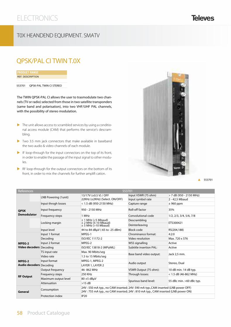
p 553701
The TWIN QPSK-PAL CI allows the user to trasmodulate two chan-nels (TV or radio) selected from those in two satellite transponders(same band and polarisation), into two VHF/UHF PAL channels,with the possibility of stereo modulation.
u The unit allows access to scrambled services by using a conditio-nal access module (CAM) that performs the service’s descram-bling.
u Two 3.5 mm jack connectors that make available in basebandthe two audio & video channels of each module.
u IF loop-through for the input connectors on the top of its front,in order to enable the passage of the input signal to other modu-les.
u RF loop-through for the output connectors on the bottom of itsfront, in order to mix the channels for further amplifi cation.
References 553701
QPSKDemodulator
LNB Powering (1unit) 13/17V (±0.5 V) / OFF22KHz (±2KHz) (Select. ON/OFF)
Input VSWR (75 ohm) > 7 dB (950 - 2150 MHz)Input symbol rate 2 - 42,5 Mbaud
Input throgh losses < 1.5 dB (950-2150 MHz) Capture range ± 960 ppm
Input frequency 950 - 2150 MHz Roll-off factor 35%
Frequency steps 1 MHz Convolutional code 1/2, 2/3, 3/4, 5/6, 7/8
Locking margin± 1 MHz (<5 Mbaud)± 2 MHz (5-10 Mbaud)± 5 MHz (>10 Mbaud)
DescramblingETS300421
Deinterleaving
Input level 44 to 84 dBμV (-65 to -25 dBm) Block code RS(204,188)
MPEG-2Video decoders
Input 1 format MPEG-1 Chrominance format: 4:2:0Decoding ISO/IEC 11172-2 Video resolution Max. 720 x 576Input 2 format MPEG-2 WSS signalling ActiveDecoding ISO/IEC 13818-2 (MP@ML) Subtitle insertion PAL: ActiveTS input rate Max. 90 Mbits/seg
Base band video output: Jack 2,5 mm.Video rate 1.5 to 15 Mbits/seg
MPEG-2Audio decoders
Input format MPEG-1, MPEG-2Audio output Stereo, Dual
Decoding LAYER 1, LAYER 2
RF Output
Output frequency 46- 862 MHz VSWR Output (75 ohm): 10 dB min. 14 dB typ.Frequency steps 250 KHz Through losses: < 1.5 dB (46-862 MHz)Maximum output level 80 ±5 dBμV
Spurious band level: 55 dBc min. >60 dBc typ.Attenuation >15 dB
GeneralConsumption 24V : 550 mA typ., no CAM inserted; 24V: 590 mA typ.,CAM inserted (LNB power OFF)
24V : 755 mA typ., no CAM inserted; 24V : 810 mA typ., CAM inserted (LNB power ON)Protection index IP20
REF. DESCRIPTION
PRODUCT RANGE
553701 QPSK-PAL TWIN CI STEREO

ELECTRONICS
59 Product Catalogue
T0X HEANDEND EQUIPMENT. SMATV
5629 5559 6 x 563101
5629 5559 6 x 5537
5629 55756 x 5537
Output
QPSK Input
p 563101
p 553701
QPSK input, 6 COFDM channels output.
QPSK input, 24 PAL channels output.
SMATV APPLICATION

ELECTRONICS
60 Product Catalogue
T0X HEANDEND EQUIPMENT. MATV
COFDM/COFDM CI T.0X
p 563401
The COFDM transmodulator to COFDM receives a DTT multiplexand demodulates it by obtaining an MPEG-2 transport packagewhich can be edited to remove and/or descramble services. TheTS is then modulated in COFDM format and converted to the out-put channel (UHF or VHF).
u TS settings in order to comply with DVB-T requirements:
u Stuffing, to perform faster scanning in the STB or when usingSTB with a fixed symbol rate.
u MUX services removing to avoid STB detection/ loading.
u LCN (Logical Channel Number) setting to facilitate the sorting ofthe services in the STB.
u The unit allows access to scrambled services by using a conditio-nal access module (CAM) that performs the service’s descram-bling.
References 563401
COFDMDemodulator
Input frequency 77-227 Mhz (VHF) 474-858 Mhz (UHF) Guard interval 1/4, 1/8, 1/16, 1/32
Connectors input/output ''F'' female Scrambling DVB ET300744
Input impedance 75 Ohm Interleaving DVB ET300744
Modulation QPSK, 16 QAM, 64 QAM Input trough losses < 1.5 dB typ
Input FEC 1/2, 2/3, 3/4, 5/6, 7/8 Input VSWR 10dB min.
COFDMModulator
Modulation QPSK, 16 QAM, 64 QAM Scrambling DVB ET300744
Guard interval 1/4, 1/8, 1/16, 1/32 Interleaving DVB ET300744
FEC 1/2, 2/3, 3/4, 5/6, 7/8 Cell_id selectable
Band width 7 Mhz, 8 Mhz Output spectrum Normal/ Inverted (Select.)
RF Output
Output frequency 45 – 862 Mhz Through losses < 1.5 dB typ
Frequency steps 166 Khz Return losses > 12 dB typ
Maximum output level 80 ±5 dBμV (progr.) Connectors input/output 'F'' female
Attenuation >15 dB (progr.) Output impedance 75 Ohm
GeneralConsumption 24V/ 320 mA
Protection index IP20
REF. DESCRIPTION
PRODUCT RANGE
563401 COFDM-COFDM CI

ELECTRONICS
61 Product Catalogue
T0X HEANDEND EQUIPMENT. MATV
COFDM/QAM CI T.0X
p 563601
The COFDM transmodulator to QAM receives a DTT multiplex anddemodulates it by obtaining an MPEG-2 transport package whichcan be edited to remove and/or descramble services. The TS isthen modulated in QAM format and converted to the outputchannel (UHF or VHF).
u TS settings in order to comply with DVB-T requirements:
u Stuffing, to perform faster scanning in the STB or when usingSTB with a fixed symbol rate.
u MUX services removing to avoid STB detection/ loading.
u LCN (Logical Channel Number) setting to facilitate the sorting ofthe services in the STB.
u The unit allows access to scrambled services by using a conditio-nal access module (CAM) that performs the service’s descram-bling.
References 563601
COFDMDemodulator
Input frequency 77-227 Mhz (VHF) 474-858 Mhz (UHF) Guard interval 1/4, 1/8, 1/16, 1/32
Connectors input/output ''F'' female Scrambling DVB ET300744
Input impedance 75 Ohm Interleaving DVB ET300744
Modulation QPSK, 16 QAM, 64 QAM Input trough losses < 1.5 dB typ
Input FEC 1/2, 2/3, 3/4, 5/6, 7/8 Input VSWR 10dB min.
QAMModulator
Modulation 16, 32, 64, 128, 256 QAM Scrambling DVB ET300744
Symbol rate 6,9 Mbaud max Interleaving DVB ET300744
Roll-off factor 15% Band width 8,3 Mhz max.
Block code RS (188,204) Output spectrum Normal/ Inverted (Select.)
QAM Output
Output frequency 45 – 862 Mhz Through losses < 1.5 dB typ
Frequency steps 166 Khz Return losses > 12 dB typ
Maximum output level 80 ±5 dBμV (progr.) Connectors input/output 'F'' female
Attenuation >15 dB (progr.) Output impedance 75 Ohm
GeneralConsumption 24 V/ 360 mA - 24 V/ 420 mA (CAM)
Protection index IP20
REF. DESCRIPTION
PRODUCT RANGE
563601 COFDM-QAM CI

ELECTRONICS
62 Product Catalogue
T0X HEANDEND EQUIPMENT. MATV
A/D PROCESSOR TWIN T.0X
p 564901
Analogue & Digital channel processor allowing conversion (diffe-rent input and output channels) or amplification ( same input andoutput channel).
u In conversion mode allows to perform a distribution network ofDTT services.
u In amplifier mode allows to equalize a DTT MUX to adapt the sig-nal level. SAW filtering gives high selectivity.
References 564901 Prog.
Input A/D RF
Input frequency range MHz 46-862 X
Frequency stepsKHz
125, 166 X
Lock margin ± 500
Input loop-though gain dB 0± 3
Filter MHz 7,8 X
Pre-amplifier powering Vdc 0, 12, 24 X
Return losses dB >10
Impedance ohm 75
Output A/D RF
Output frequency range MHz 46-862 X
Frequency steps KHz 125 (digital), 166 (digital), 250 (analog.) X
Max. output level dBμV 80 typ.
Regulation margin dB 65-80 X
Spurious level dBc >55
END (Equivalent Noise Degradation)
dB
<2
Loop-though loss <1,5
Return losses > 12
Impedance ohm 75
General
Powering Vdc 24
Consumption mA 350
Protection index IP 20
REF. DESCRIPTION
PRODUCT RANGE
564901 A/D PROCESSOR TWIN

ELECTRONICS
63 Product Catalogue
T0X HEANDEND EQUIPMENT. MATV
A/V MODULATOR TWIN T.0X
p 5806
Ref. 5806 features two A/V inputs (modules A and B) whichgenerate two independent output channels. The A/Vinputs for each module are modulated according to the TVstandard in an IF of 38.9 Mhz. The modulated IF signal isconverted to any channel or frequency between 46 and862 Mhz.
u VSB output
u Audio and video parameters configurable to set thesignal in any standard.
u 9 possible channel tables : CCIR N.Z. Ind, China Taiwan,Chile M/N, Italy, France, Russia (OIR), Ireland, South Africa,Poland and Australia.
u Test socket (-30 dB) , located in the upper part of the frontpanel.
References 5806
Video
Bandwidth 0,00005 ... 5 MHz Differencial phase < 4°
input level (75 ohm) 1 Vpp Chroma/luma Delay < 100 ns
Modulation depth 72,5 ... 90 % Chroma/luma Delay > 52 dB
Differencial gain < 4 % Flatness < +1 dB
Audio
Bandwidth 0,04 ... 15 KHz S/N Ratio > 45 dB
Impedance 10000 ohm Flatness < ±1 dB
Pre-emphasis 0 μS Input level >-15 <7 dBm
Deviation (1KHz/1.7Vpp input) program. (see table) Distortion (1KHz dev. ± 30KHz) < 1 %
RF Output
Output frequency 46 ... 862 MHz Return loss 10 dB (14 typ)
Impedance 75 ohm.)Audio carrier precision
VHF < 25 KHz
Output level 80 ± 5 dBμV UHF < 50 KHz
Regulation margin > 15 dBVideo carrier precision
VHF < 15 KHz
Level stability ± 3 dB UHF < 30 KHz
Pa/Pv distance -12, -16 (prog.) Carrier ratio (MHz): 4,5 / 5,5 / 6 / 6,5
IF Frequency 38,9 MHz Band spurious level46 ... 862MHz: 55 dBc min. > 60 dBc typ
Frequency steps 250 KHz (prog.)
C/N (5 MHz) > 56 dB Through losses (46 - 862 MHz): < 1.5 dB
GeneralPower supply 24 V
Protection index IP20Comsuption 24 V 300 mA
REF. DESCRIPTION
PRODUCT RANGE
5806 A/V MODULATOR TWIN

ELECTRONICS
64 Product Catalogue
T0X HEANDEND EQUIPMENT. CDC
p 5559/555901
Device that allows remote control and monitoring of a T.0XTeleves headend. Ref. 5559 uses a 10/100 Mbps ethernet interfaceand Ref. 555901 has a GSM/GPRS internal modem.
u Headend's management and monitoring uses a centralizesystem '' Televes Services ''. The portal is located in our headquar-ters. Access is granted previous identification.
u Built-in RISC Micro under GNU/Linux OS assures 100% reliabilitywhen managing external interfaces end protocols.
References 5559/555901
FirmwareOperating system Linux Kernel 2.6.16Boot manager U-boot 1.1.3.
File system jffs2
Hardware
Radio GSM/GPRS(only ref. 555901)
Frequency
MHz
GSM 850/900
DCS 1.800
PCS 1.900
Bandwidth
EGSM 80GSM 150DCS 170
PCS 140
Transmission power
dBm
GSM +33
DCS +30
PCS +30
Sensitivity
GSM -107
DCS -106
PCS -106CPU AT91RM9200
Memory
Flash
MB
8
SD RAM 64
NAND Flash 128 X 8bit
Connexions
USB 2.0 Full Speed Host (12 Mbps)
RJ45 1 Ethernet 10/100 Base-T
RJ45 2 Remote PCT-5.0
SIM Card reader
F (only ref. 555901) Antenna GSM/GPRS (only ref. 555901)
GeneralPowering Vdc 24
Consumption mA 220 (ref. 5559) / 292 (ref. 555901)
Protection Index IP 20
CDC IP/GPRS T.0X
REF. DESCRIPTION
PRODUCT RANGE
5559 CDC IP
555901 CDC IP GSM/GPRS
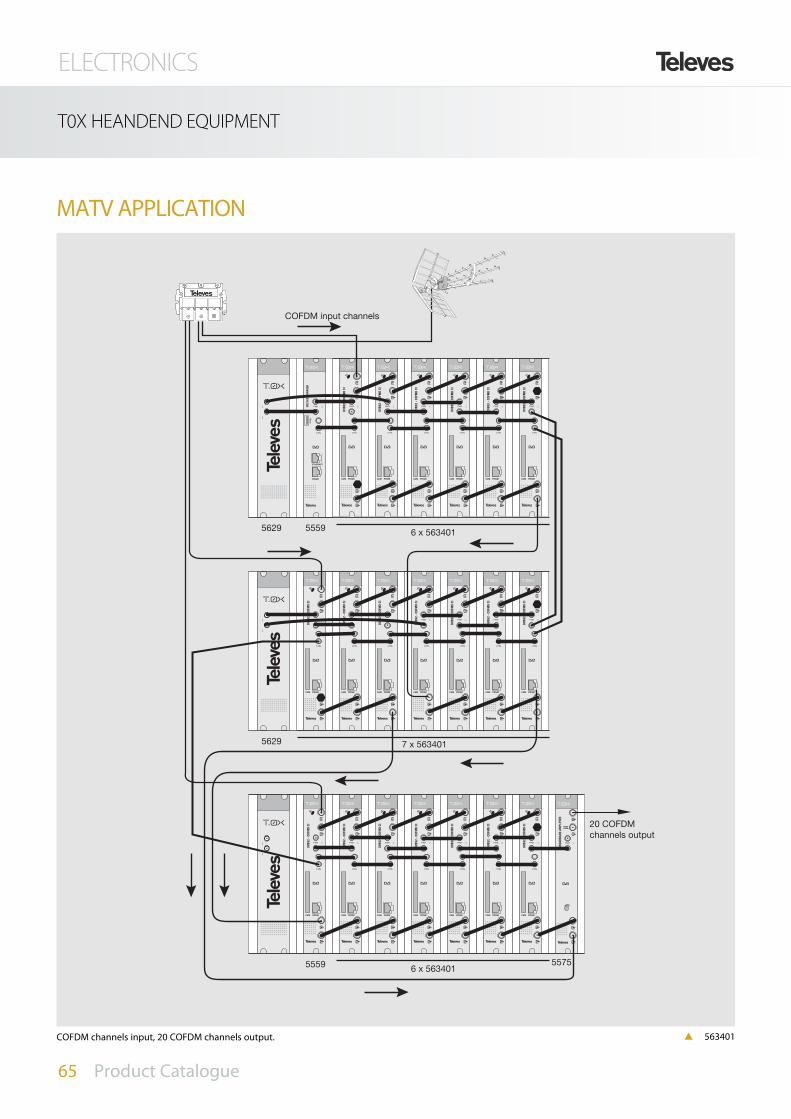
ELECTRONICS
65 Product Catalogue
T0X HEANDEND EQUIPMENT
MATV APPLICATION
5575
5629 5559 6 x 563401
5629 7 x 563401
5559 6 x 563401
20 COFDMchannels output
COFDM input channels
p 563401COFDM channels input, 20 COFDM channels output.

ELECTRONICS
66 Product Catalogue
T0X HEANDEND EQUIPMENT. MATV
MATV APPLICATION
5629 55596 x 563601
5629 7 x 563601
Entrada canales COFDM
17 QAMchannels output
p 563401COFDM channels input, 17 QAM channels output.

ELECTRONICS
67 Product Catalogue
T05 HEANDEND EQUIPMENT
CDC system
5059 Headend controller CDC
Ref. DeSCRIPTION PRODUCT RANGE
The headend controller allows remote control of a headend byusing an external modem connected to the phone line or local con-trol by connecting a PC directly to the headend controller.
The offered services are: Remote programming of devices.
Headend’s state monitorization
Upload the configuration of the headend from a PC.
Generate a private TV channel.
State screen information of the headend devices.
502905 PSU
5075 Hybrid amplifier MATV
2168 PC programming Sw. + Accs.
7234 Universal Programming Unit
5837 Modem IP
Mounting & accessories
5071 Wall mount (10M+PSU)
5239 Wall mount (12M+PSU)
5301 19” Rack frame (10M+PSU)
5072 Lockable cabinet (10M+PSU)
5069 Lockable cabinet (14M+PSU)
5235 Lockable cabinet (22M+PSU)
5073 Blank plate
4061 F type 75 ohms load DC blocked
System accessories
References 5059Devices management
Max. number of devices in the bus 254
Bus control RS485, 3 thread
OSD Management
Headend information screen 4 screen max.
Programmable data screen 4 screen max.
Delay between sreens programmable
Modem connection
External modem serie, compatible AT 9600 baud
Transmition speed 9600 baud
RF VSB Output
Output frequency MHz 46-862 (or list of channels)
Frequency steps kHz 250
Max. output level dBµV 80±5 (programmable)
Regulation margin
dB
15
USWR Output 14 typ.
Bypass losses <1.5
Spurious dBc 60 typ.
TV standard PAL / NTSC
General
Consumption A (Vdc) 0.6 (5); 0.2 (15) Device management CDC
p 5059

ELECTRONICS
68 Product Catalogue
REMOTE HEADEND CONTROLLER
5837 IP Modem
5836 GSM Modem
Ref. DeSCRIPTION
PRODUCT RANGE
CDC System – Modem
TDT QPSK-PAL QPSK-PAL QPSK-PAL QPSK-PAL QOFDM-PALQOFDM-PAL QOFDM-PAL
Direc. 1 Direc. 2 Direc. 3 Direc. 4 Direc. 5 Direc. 6 Direc. 7 Direc. 8 Direc. 9 Direc. 10 Direc. 0
Modem
CDC MODEM
Satellite input Terrestrial input
Headend local connection
headend remote connection
RS485 Control Bus
Telephone line
T Y P I C A L A P P L I C A T I O N
References 5837
Serial Interface RS232 (TX/RX)
Routing Buffer 12 Kbytes x 2
Ethernet Connection 10/100 BaseT
CDC Communication RJ45 (RS232, TX/RX)
Consumption (5V) mA 500
p 5837

ELECTRONICS
69 Product Catalogue
T05 HEANDEND EQUIPMENT
A/V - COFDM Modulator
5540 ASI - COFDM
5541 MPEG-2 QUAD encoder
Ref. DeSCRIPTION PRODUCT RANGE
Adapts analogue signals to DTT receiver/tv sets.
Control of the input signals degree of compression using the MPEG2encoder (ref. 5541).
The A/V inputs are fully independent, allowing for different degreesof quality depending on the service (sports, news, etc)
Locally (front panel) or remotely (IP protocol) configurable.
All-band output.
Generates a DTT multiplex (COFDM) from 4 analogue A/V signals.
Reference 5540Standard EN 50083-9
COFDMModulation
Bandwidth MHz 7-8
Modulation QPSK, 16QAM O 16 QAM
IG µS
1/4, 1/8, 1/16, 1/32
FEC 1/2, 2/3, 3/4, 5/6, 7/8
OutputFrequency MHz 117,5-226,5 / 474-858
Offset KHz 125 - 166
Power SupplyPowering Vdc 5 - 15 - 18
Consumption mA 350(5V)-175(15V)-70 (18V)
Reference 5541
Standard ISO/ICE11172
ISO/ICE13818
Video
Codification MPEG-2 MP@ML (4:2:0)
Input CVBS, S-VIDEO
Bit Rate Mbps 1,5 - 15
AudioCodification MPEG-1 Layer 1
S.R. KHz 32, 44.1, 48
ControlLCD + frontal keyboard
Remote control SMNP
MPEG OutputASI Bit Rate Mbps 170
Package 188/204
Power SupplyPowering Vac 90-260
Consumption W 350(5V)-175(15V)-70 (18V)
ASI- COFDM
1
R/C
5
6
5541 - MPEG QUAD ENCODER
POWER ALARM
ENTER MENU LOCK
A/V1 A/V2 A/V3 A/V4
Ref. 5540
Ref. 5541
T Y P I C A L A P P L I C A T I O N
p 5540p 5541

ELECTRONICS
70 Product Catalogue
T05 HEANDEND EQUIPMENT
5541 - MPEG QUAD ENCODER
POWER ALARM
ENTER MENU LOCK
TS proc TS proc ASI- COFDM
SAT
UHF
ASI-out
Output
A/V1 A/V2 A/V3 A/V4T Y P I C A L A P P L I C A T I O N
Application example where 4 A/V analogue sources (cameras,DVD players...) are converted to a DTT multiplex that is thenmixed with two additional TVSAT content multiplexes (DVB/S2-COFDM transmodulator ref. 5181).
These three COFDM multiplexes are amplified with T03 unitsand then mixed with the DTT signal received in the antennaresulting in a headend that permits the reception of analogueservices and digital satellite contents in our DTT adapters/recei-vers.
A/V - COFDM Modulator

ELECTRONICS
71 Product Catalogue
T05 HEANDEND EQUIPMENT
Analogue / Digital Channel Processor
T Y P I C A L A P P L I C A T I O N
5179 A/D Channel Processor
Ref. DeSCRIPTION PRODUCT RANGE
Analogue & digital channel pro-cessor allowing the conversionor just processing of both digital& analogue channels. Fullyinput/output agile through thefull VHF & UHF band. The pro-duct can also be used as chan-nel processor using sameinput/output channel. Theinput AGC guarantees a stableoutput level.
Programmable parameters:
• Freq./Channel (Input / output).• Output level• Converter/Amplifier• Channel slope.• Analogue/Digital mode. • Input bandwidth 7/8 MHz• Remotely controllable via CDC
References 5179
Input
Input frequency range MHz 46...862
Frequency steps KHz D:166.66/125A:250
Input level dBµV 50-82 (AGC)
Input loop-through loss dB 0±3
Output
Output frequency range MHz 46...862
Frequency steps KHz D:166.66/125A: 250
Max. output level dBµV 80±5
Regulation margin
dB
15
Return loss >10
Slope adjustment ±3
Output Loop-through loss <1.5
Equivalent noise degradation (END) <2
General
Consumption mA (Vdc) 500 (5); 150 (15)
Preamplifier power Vdc 12/24 (UHF in)
Dimensions mm 35x197x163
502905 PSU
5075 Hybrid amplifier MATV
2168 PC programming Sw. + Accs.
7234 Universal Programming Unit
5837 Modem IP
Mounting & accessories
5071 Wall mount (10M+PSU)
5239 Wall mount (12M+PSU)
5301 19” Rack frame (10M+PSU)
5072 Lockable cabinet (10M+PSU)
5069 Lockable cabinet (14M+PSU)
5235 Lockable cabinet (22M+PSU)
5073 Blank plate
4061 F type 75 ohms load DC blocked
System accessories
p 5179

ELECTRONICS
72 Product Catalogue
T05 HEANDEND EQUIPMENT
References 505403 / 504403COFDM demodulator Input through losses dB 1,2
Input frequency MHz
174-230 / 474-858 (or channel tables)
Frequency steps 1Locking margin ±3
Input level dBµV 49 to 89 (8k; 64 QAM;FEC 2/3)
Return losses dB >12 (46-862 MHz)
Bandwidth filter SAW MHz 7 - 8 programmable
FFT 2k; 8kConstellation QPSK; 16QAM; 64 QAMGuard interval 1/4; 1/8; 1/16; 1/32Viterbi rate 1/2; 2/3; 3/4; 5/6; 7/8Max. symbol rate Mbaud 31.67MPEG DecoderInput format TS MPEG-2/DVBDecoding MP@MLTS input rate
Mbps60 max.
Video rate 1.5 to 15Video resolution Max. 720x576Video output composite PALRF VSB OutputOutput frequency MHz 46-862 (or channel tables)Frequency steps KHz 250 Max. Output level dBµV 80±5Variable gain
dB15
Return losses 14 typ. Through losses <1.5 Spurious band level dBc 60 typ. GeneralConsumption A (Vdc) 1.2 (5) / 0.4 (15) Preamplifier PSU mA 50 (0-12-24Vdc, prog.)Dimensions mm 35x197x163
COFDM-PAL
Ref. DeSCRIPTION PRODUCT RANGE
Transforms a terrestrial digital chan-nel to an analogue channel either inVHF or UHF.
Programmables parameters:
• Input and output channel.• Output level.• Video and Audio program selection.• Video modulation index.• Audio deviation.• Audio carrier frequency.• A/V ratio• Remotely controllable via the CDC.
T Y P I C A L A P P L I C A T I O N
505403 COFDM-PAL
504403 COFDM-PAL stereo
502905 PSU
5075 Hybrid amplifier MATV
2168 PC programming Sw. + Accs.
7234 Universal Programming Unit
5837 Modem IP
Mounting & accessories
5071 Wall mount (10M+PSU)
5239 Wall mount (12M+PSU)
5301 19” Rack frame (10M+PSU)
5072 Lockable cabinet (10M+PSU)
5069 Lockable cabinet (14M+PSU)
5235 Lockable cabinet (22M+PSU)
5073 Blank plate
4061 F type 75 ohms load DC blocked
System accessories
CONTROL MODEvia modem PC
p 505403

ELECTRONICS
73 Product Catalogue
T05 HEANDEND EQUIPMENT
IF / IF processors
586301 Single IF processor DVBS2
586401 Triple IF processor DVBS2
Ref. DeSCRIPTION PRODUCT RANGE References 586301 586401
Input freq. margin
MHz
950-2150
Output freq. margin 950-2150
Frequency steps 1
Output impedance W 75
Input return lossesdB
>10
Output return losses >10
BW of the selected channel MHz 10 a 72 (2 MHz steps)
Input leveldBµV
60 - 88
Output level 75±5
Level regulator Yes
Powering LNB Vdc 13/17 / OFF22 KHz / OFF
General
Max. consumption mA 5V:55015V:50
5V:110015V:50
Protection index IP 20
Programmable parameters:
• Modular and programmable sate-llite system.
• Allows the selection of any chan-nel in the IFband to be shifted intoanother channel inside the band.• Remotely controllable via theCDC.
Ref. 586401
SalidaMATV + FI
B. Alta V
B. Baja V
B. Alta H
Ref. 5437MATV
Ref. 5865
B. Alta V
I F A M P L I F I E R
References 5865Frequency range MHz 950···2150Gain (950 MHz)
dB35±2
Gain (2150 MHz) 40±3 Adjustable margin 20
Output voltage (2 tones -35dB) dBµV >123
Connector “F” Powering Vdc 15Consumption mA(vdc) 200(15)
T Y P I C A L A P P L I C A T I O N
CONTROL MODEvia modem PC
502905 PSU
5075 Hybrid amplifier MATV
2168 PC programming Sw. + Accs.
7234 Universal Programming Unit
5837 Modem IP
Mounting & accessories
5071 Wall mount (10M+PSU)
5239 Wall mount (12M+PSU)
5301 19” Rack frame (10M+PSU)
5072 Lockable cabinet (10M+PSU)
5069 Lockable cabinet (14M+PSU)
5235 Lockable cabinet (22M+PSU)
5073 Blank plate
4061 F type 75 ohms load DC blocked
System accessories
p 586301

ELECTRONICS
74 Product Catalogue
T05 HEANDEND EQUIPMENT
502905 Switched PSU T-03/T-05
5030 Switched PSU T-03 / T-05 110 Vac UL
5498 Switched PSU T-03
MATV Hybrid amplifier
Hybrid amplifier for headendequipment. Provided with 2 inputsto mix its output with channelscomming from different systems.
PSU
References 502905 / 5030 * 5498Mains voltage Vac 230±15
Frequency Hz 50/60
Output voltage Vdc 24 18 15 5 24
Max. output current A 0.55 0.8 4.2 (*) 6.6 2.5
Max. output powering W 13.2 14.4 63 (*) 33 60
Dimensions mm 56x197x163 55x197x83
*24 and/or 18V voltage are obteined from 63W (15V) PSU
References 5075Frequency range MHz 47-862
GaindB
45±2
Gain regulation 20
Output level
DIN 45004-B
dBµV
120
IMD3 (-60 dB, 2c) 117
IMD2 (-60 dB, 2c) 111
CTB (-60 dB, 42c) 105
CSO (-60 dB, 42c) 105
XMOD (-60 dB, 42c) 105
Noise figure dB <10
General
Powering voltage Vdc 15
Consumption A 0.8
Dimensions mm 35x197x163
Switched PSU for the T03 and T05 range.
Ref. DeSCRIPTION PRODUCT RANGE
5075 MATV Hybrid amplifier
Ref. DeSCRIPTION PRODUCT RANGE
p 5075
p 502905

ELECTRONICS
75 Product Catalogue
HEADEND EQUIPMENT
Cabinets and supports
5071 Wall mount (10M+PSU)
5239 Wall mount (12M+PSU)
5301 19” Rack frame (10M+PSU)
5072 Lockable cabinet (10M+PSU)
507202 Lockable cabinet T0X
(7M+PSU) with ventilation
5069 Lockable cabinet (14M+PSU)
5235 Lockable cabinet (22M+PSU)
5334 T03/T05 Ventilation system
5750 Outdoor cabinet
5331 19” Rack cabinet (30M) + accessories
5332 19” Rack cabinet (40M) + accessories
Ref. DeSCRIPTION PRODUCT RANGE 5071/5239
Accessories
5073 Blank plate T05
5673 Blank plate T0X
4061 F type 75 ohms load DC blocked
5074 Link F connector
4221 Power injector
7234 Universal programmer
4947 Coaxial surge arrestor
422601 Power lead for T0X with T05 PSU
422602 Data lead for T0X with T05 CDC
Ref. DeSCRIPTION PRODUCT RANGE
References 5072 5069 5235 5750
c
b
a
a 610 760 1060 440
b 295 440
c 235 140
Ref.5069Compatible
p 5750
p 5071/5239
p 5301
p 5073
p 7234p 4947
p 4221
p 5074p 4061
p 5334
p 5069/5235/5072

ELECTRONICS
76 Product Catalogue
MULTISWITCHES
Splitters and LNB switches
7268 DiSEqC 2in/1out switch
7269 DiSEqC 4in/1out switch
Ref. DeSCRIPTION PRODUCT RANGE
References 7268 7269
Bandwidth MHz 0···2400 5···2150
Switching type DiSEqC 2.0 DiSEqC 2.0
IF through losses
dB
<1.5 <6
RF through losses <1.5 <6
Input rejection >20 >20
Max. current bypass mA 250 290
Powering Vdc 12-20 12-20
Dimensions mm 95x75x26 137x130x56
Ref. 7268
7475 7475
T Y P I C A L A P P L I C A T I O N
7475 7475
Ref. 7269
2 x 7475
OFF
Ref. 7269
ON
747574757611
LNBmonobloco A/B
LNBuniversal C
LNB A+B
LNBuniversal D
4 L N B U n i .T Y P I C A L A P P L I C A T I O N
T Y P I C A L A P P L I C A T I O N M o n o b l o c k + 2 L N B U n i .
p 7268 p 7269

ELECTRONICS
77 Product Catalogue
MULTISWITCHES
Universal Multimat System
7101 Main multiswitch
7102 MATV/IF passive combiner 13 dB
7108 MATV/IF passive combiner 9 dB
7109 MATV/IF passive combiner 17 dB
7110 MATV/IF passive combiner 21 dB
7103 Multimat PSU
7104 Multimat IF amplifier
7105 F terminal load block
7106 F connector block
7107 F terminal load DC block
Ref. DeSCRIPTION PRODUCT RANGE
7105 7105 71057105
+13V
+18V
GND
Mains 180-264 Vac / 50 Hz
DC outputs 18 Vdc / 1200 mA
13 Vdc / 300 mA
Consumption 300 mA / 230 V
Short Circuit protection
7103
V/ low14 V/0 KHz
H/ high18 V/22 KHz
H/ low18 V/0 KHz
V/ high14 V/22 KHz
14 V/0 KHzV/ low
18 V/22 KHzH/ high
18 V/0 KHzH/ low
14 V/22 KHzV/ high
Frequency range 950 - 2400 MHzInsertion losses 6-0 dBIsolation 40 dB typMax. input level 92 dBµVThrough losses trunkline 1 - 2.5 dB
Outp
uts
to re
ceiv
ers/
Com
bine
r
Inputs
from
nex
t Uni
t
OFF/ON
InputsDC-plug Power Supply -------
7101Cascade Outputs
1234
1
2
3
4
Outp
uts
to re
ceive
rs
I. F
. in
puts
InputTerrestrial
7108
Output
Freq
uenc
y ra
nge
- Ter
r.: 5
- 86
2 M
Hz
Sat.:
950
- 24
00 M
Hz
Inse
rtion
loss
es -
Terr.
: 13
dB
Sat.:
2 d
BTh
roug
h lo
sses
- Te
rr.:
3 dB
Terrestrial
V/ low14 V/0 KHz
H/ high18 V/22 KHz
H/ low18 V/0 KHz
V/ high14 V/22 KHz
14 V/0 KHzV/ low
18 V/22 KHzH/ high
18 V/0 KHzH/ low
14 V/22 KHzV/ high
Frequency range 950 - 2400 MHzInsertion losses 6-0 dBIsolation 40 dB typMax. input level 92 dBµVThrough losses trunkline 1 - 2.5 dB
Outp
uts
to re
ceiv
ers/
Com
bine
r
Inputs
from
nex
t Uni
t
OFF/ON
InputsDC-plug Power Supply -------
7101Cascade Outputs
1234
1
2
3
4
Outp
uts
to re
ceive
rs
I. F
. in
puts
InputTerrestrial
7102
Output
Freq
uenc
y ra
nge
- Ter
r.: 5
- 86
2 M
Hz
Sat.:
950
- 24
00 M
Hz
Inse
rtion
loss
es -
Terr.
: 13
dB
Sat.:
2 d
BTh
roug
h lo
sses
- Te
rr.:
3 dB
Terrestrial
T Y P I C A L A P P L I C A T I O N
p 7101p 7107
p 7105 p 7106 p 7104

ELECTRONICS
78 Product Catalogue
MULTISWITCHES
7105
+13V
+18V
GND
Mains 180-264 Vac / 50 Hz
DC outputs 18 Vdc / 1200 mA
13 Vdc / 300 mA
Consumption 300 mA / 230 V
Short Circuit protection
7103
V/ low14 V/0 KHz
H/ high18 V/22 KHz
H/ low18 V/0 KHz
V/ high14 V/22 KHz
14 V/0 KHzV/ low
18 V/22 KHzH/ high
18 V/0 KHzH/ low
14 V/22 KHzV/ high
Frequency range 950 - 2400 MHzInsertion losses 6-0 dBIsolation 40 dB typMax. input level 92 dBµVThrough losses trunkline 1 - 2.5 dB
Outp
uts
to re
ceiv
ers/
Com
bine
r
Inputs
from
nex
t Uni
t
OFF/ON
InputsDC-plug Power Supply -------
7101Cascade Outputs
1234
1
2
3
4
1234
7105
+13V
+18V
GND
Mains 180-264 Vac / 50 Hz
DC outputs 18 Vdc / 1200 mA
13 Vdc / 300 mA
Consumption 300 mA / 230 V
Short Circuit protection
7103
V/ low14 V/0 KHz
H/ high18 V/22 KHz
H/ low18 V/0 KHz
V/ high14 V/22 KHz
14 V/0 KHzV/ low
18 V/22 KHzH/ high
18 V/0 KHzH/ low
14 V/22 KHzV/ high
Frequency range 950 - 2400 MHzInsertion losses 6-0 dBIsolation 40 dB typMax. input level 92 dBµVThrough losses trunkline 1 - 2.5 dB
Outp
uts
to re
ceiv
ers/
Com
bine
r
Inputs
from
nex
t Uni
t
OFF/ON
InputsDC-plug Power Supply -------
7101Cascade Outputs
1234
1
2
3
4
1234
5678
7105
+13V
+18V
GND
Mains 180-264 Vac / 50 Hz
DC outputs 18 Vdc / 1200 mA
13 Vdc / 300 mA
Consumption 300 mA / 230 V
Short Circuit protection
7103
V/ low14 V/0 KHz
H/ high18 V/22 KHz
H/ low18 V/0 KHz
V/ high14 V/22 KHz
14 V/0 KHzV/ low
18 V/22 KHzH/ high
18 V/0 KHzH/ low
14 V/22 KHzV/ high
Frequency range 950 - 2400 MHzInsertion losses 6-0 dBIsolation 40 dB typMax. input level 92 dBµVThrough losses trunkline 1 - 2.5 dB
Outp
uts
to re
ceiv
ers/
Com
bine
r
Inputs
from
nex
t Uni
t
OFF/ON
InputsDC-plug Power Supply -------
7101Cascade Outputs
1234
1
2
3
4
Outp
uts
to re
ceive
rs
I. F
. in
puts
InputTerrestrial
7108
Output
Freq
uenc
y ra
nge
- Ter
r.: 5
- 86
2 M
Hz
Sat.:
950
- 24
00 M
Hz
Inse
rtion
loss
es -
Terr.
: 13
dB
Sat.:
2 d
BTh
roug
h lo
sses
- Te
rr.:
3 dB
Terrestrial
V/ low14 V/0 KHz
H/ high18 V/22 KHz
H/ low18 V/0 KHz
V/ high14 V/22 KHz
14 V/0 KHzV/ low
18 V/22 KHzH/ high
18 V/0 KHzH/ low
14 V/22 KHzV/ high
Frequency range 950 - 2400 MHzInsertion losses 6-0 dBIsolation 40 dB typMax. input level 92 dBµVThrough losses trunkline 1 - 2.5 dB
Outp
uts
to re
ceiv
ers/
Com
bine
r
Inputs
from
nex
t Uni
t
OFF/ON
InputsDC-plug Power Supply -------
7101Cascade Outputs
1234
1
2
3
4
Outp
uts
to re
ceive
rs
I. F
. in
puts
InputTerrestrial
7102
Output
Freq
uenc
y ra
nge
- Ter
r.: 5
- 86
2 M
Hz
Sat.:
950
- 24
00 M
Hz
Inse
rtion
loss
es -
Terr.
: 13
dB
Sat.:
2 d
BTh
roug
h lo
sses
- Te
rr.:
3 dB
Terrestrial
1234
5678
7105
+13V
+18V
GND
Mains 180-264 Vac / 50 Hz
DC outputs 18 Vdc / 1200 mA
13 Vdc / 300 mA
Consumption 300 mA / 230 V
Short Circuit protection
7103
V/ low14 V/0 KHz
H/ high18 V/22 KHz
H/ low18 V/0 KHz
V/ high14 V/22 KHz
14 V/0 KHzV/ low
18 V/22 KHzH/ high
18 V/0 KHzH/ low
14 V/22 KHzV/ high
Frequency range 950 - 2400 MHzInsertion losses 6-0 dBIsolation 40 dB typMax. input level 92 dBµVThrough losses trunkline 1 - 2.5 dB
Outp
uts
to re
ceiv
ers/
Com
bine
r
Inputs
from
nex
t Uni
t
OFF/ON
InputsDC-plug Power Supply -------
7101Cascade Outputs
1234
1
2
3
4
Outp
uts
to re
ceive
rs
I. F
. in
puts
InputTerrestrial
7108
Output
Freq
uenc
y ra
nge
- Ter
r.: 5
- 86
2 M
Hz
Sat.:
950
- 24
00 M
Hz
Inse
rtion
loss
es -
Terr.
: 13
dB
Sat.:
2 d
BTh
roug
h lo
sses
- Te
rr.:
3 dB
Terrestrial
V/ low14 V/0 KHz
H/ high18 V/22 KHz
H/ low18 V/0 KHz
V/ high14 V/22 KHz
14 V/0 KHzV/ low
18 V/22 KHzH/ high
18 V/0 KHzH/ low
14 V/22 KHzV/ high
Frequency range 950 - 2400 MHzInsertion losses 6-0 dBIsolation 40 dB typMax. input level 92 dBµVThrough losses trunkline 1 - 2.5 dB
Outp
uts
to re
ceiv
ers/
Com
bine
r
Inputs
from
nex
t Uni
t
OFF/ON
InputsDC-plug Power Supply -------
7101Cascade Outputs
1234
1
2
3
4
Outp
uts
to re
ceive
rs
I. F
. in
puts
InputTerrestrial
7102
Output
Freq
uenc
y ra
nge
- Ter
r.: 5
- 86
2 M
Hz
Sat.:
950
- 24
00 M
Hz
Inse
rtion
loss
es -
Terr.
: 13
dB
Sat.:
2 d
BTh
roug
h lo
sses
- Te
rr.:
3 dB
Terrestrial
V/ low14 V/0 KHz
H/ high18 V/22 KHz
H/ low18 V/0 KHz
V/ high14 V/22 KHz
14 V/0 KHzV/ low
18 V/22 KHzH/ high
18 V/0 KHzH/ low
14 V/22 KHzV/ high
Frequency range 950 - 2400 MHzInsertion losses 6-0 dBIsolation 40 dB typMax. input level 92 dBµVThrough losses trunkline 1 - 2.5 dB
Outp
uts
to re
ceiv
ers/
Com
bine
r
Inputs
from
nex
t Uni
t
OFF/ON
InputsDC-plug Power Supply -------
7101Cascade Outputs
1234
1
2
3
4
Outp
uts
to re
ceive
rs
I. F
. in
puts
InputTerrestrial
7109
Output
Freq
uenc
y ra
nge
- Ter
r.: 5
- 86
2 M
Hz
Sat.:
950
- 24
00 M
Hz
Inse
rtion
loss
es -
Terr.
: 13
dB
Sat.:
2 d
BTh
roug
h lo
sses
- Te
rr.:
3 dB
Terrestrial
1234
9101112
5678
T Y P I C A L A P P L I C A T I O N T Y P I C A L A P P L I C A T I O N
T Y P I C A L A P P L I C A T I O N T Y P I C A L A P P L I C A T I O N
Star distribution
Star distribution + MATV
4 Users 8 Users
8 Users 12 Users

ELECTRONICS
79 Product Catalogue
MULTISWITCHES
References 7101No. inputs (SAT)
No
4
No. outputs
for receivers 4
for cascading 4
for expansion 4
Frequency range MHz 950
Through losses
Receiver output
dB
< 6
Cascade output < 2
Expansion output < 1
IsolationBetween inputs 35
High band - Low band 35
Input return losses 8
Max. input level dBµV
92
Max. output level for receiver 89
Max. DC current consumption for receivermA
65
Max. DC bypass current 1200
Switching selection voltage V/H Vdc 15.5
Switching voltage selection high band 22 KHz
Selection inputs from extension DiSEqC 1.1
Max. No. of connected extensionsNo
4Max. No. of inputs 16
LNB powering mode External
Recommended PSU (switched-mode) Vdc/A 18 / 1.213 / 0.3
Dimensions mm 115x115x33
References 7108 7102 7109 7110
No. inputs VHF/UHF passive
No
1 1 1 1
No. outputs
for receivers 4 4 4 4
for cascading 1 1 1 1
for expansion 4 4 4 4
Frequency range MHz 5 - 860
Through-LossCascade output
MATVdB
< 3
SAT < 2
IsolationSAT - TV
dB> 30
TV - SAT > 35
Tap losses for receiver dB 9 13 17 21
Dimensions mm 115x70x33
References 7103Mains voltage Vac 180 - 264
Output voltage Vdc 18 ± 5%
13 ± 5%
Current A(Vdc) 1.2 (18)
0.3 (13)
Maximum power consumption W 30
Max. short-circuit current A(Vdc) 2 (18)
1 (13)
EMI/EMC standard EN55022 (B)
Safety standard EN60950
Temperature range ºC -20···+60
Dimensions mm 105x65x33
References 7104
Nº de inputs SATNº
4
Nº de outputs 4
Frequency range MHz 950 - 2400
Gain
@ 950 MHz
dB
3.5 ± 0.5
@ 2000 MHz 8.5 ± 0.5
@ 2400 MHz 9.5 ± 0.5
Isolation trunkline >45
Return-loss inputs >10
Return-loss outputs >10
Max. input leveldBµV
95
Max. output level 105
Max. current consumption (from SMPS) mA 4 x 25
Max. bypass current A 1.2
Dimensions mm 97x70x33
V/ low14 V/0 KHz
H/ high18 V/22 KHz
H/ low18 V/0 KHz
V/ high14 V/22 KHz
14 V/0 KHzV/ low
18 V/22 KHzH/ high
18 V/0 KHzH/ low
14 V/22 KHzV/ high
Frequency range 950 - 2400 MHzInsertion losses 6-0 dBIsolation 40 dB typMax. input level 92 dBµVThrough losses trunkline 1 - 2.5 dB
Outp
uts
to re
ceiv
ers/
Com
bine
r
Inputs
from
nex
t Uni
t
OFF/ON
InputsDC-plug Power Supply -------
7101Cascade Outputs
1234
1
2
3
4
5 - 862 MHz Sat.: 950 - 2400 MHzI 13 dB Sat.: 2 dBT 3 dB
T
5 - 862 MHz Sat.: 950 - 2400 MHzI 13 dB Sat.: 2 dBT 3 dB
Outputs to receivers
I. F. inputs
Inp
ut
Terrestrial
7108
Ou
tpu
t
Frequency range - Terr.: 5 - 862 MHz Sat.: 950 - 2400 MHzInsertion losses - Terr.: 13 dB Sat.: 2 dBThrough losses - Terr.: 3 dB
Terrestrial
5 - 862 MHz Sat.: 950 - 2400 MHzI 13 dB Sat.: 2 dBT 3 dB
-
5 - 862 MHz Sat.: 950 - 2400 MHzI 2 dBT 3 dB
T
Inputs
I. F. inputs
7104Frequency range - Terr.: 5 - 862 MHz Sat.: 950 - 2400 MHzInsertion losses - Terr.: 13 dB Sat.: 2 dBThrough losses - Terr.: 3 dB
+13V
+18V
GND
Mains 180-264 Vac / 50 Hz
DC outputs 18 Vdc / 1200 mA
13 Vdc / 300 mA
Consumption 300 mA / 230 V
Short Circuit protection
7103
-
5 - 862 MHz Sat.: 950 - 2400 MHzI 2 dBT 3 dB
T
5 - 862 MHz Sat.: 950 - 2400 MHzI 13 dB Sat.: 2 dBT 3 dB

ELECTRONICS
80 Product Catalogue
MULTISWITCHES
5 input stand alone
713601 5x4 Multiswitch
713701 5x6 Multiswitch
713801 5x8 Multiswitch
713901 5x12 Multiswitch
714001 5x16 Multiswitch
717001 5x24 Multiswitch
716901 5x32 Multiswitch
7321 PSU 1.6A
7328 PSU 3A
Ref. DeSCRIPTION PRODUCT•RANGE
T Y P I C A L A P P L I C A T I O N
Power Supply Units
References 7321 7328
Input voltage Vac 180-264
Mains frequency Hz 47-63
Output voltage Vdc 12
Max. out. current mA 1600 3000
Multiswitch specs 5×4 5×6 5×8 5×12 5×16 5×24 5×32
References 713601 713701 713801 713901 714001 717001 716901
Frequency rangeSAT
MHz950 - 2400
TER 47 - 862
Input levelSAT
dBµV
100
TER 100
Tap Output levelSAT 100
TER 100
Tap lossesSAT
dB
3±5 3±5 3±5 3±6 3±6 5±6 6±6
TER 3±3 3±3 3±3 5±3 5±3 9±3 9±3
Isolation between inputs 60 40 30 45 35 40 40
Isolation between outputs 20 20 30 25 25 35 35
LNB powering mA 300/input; 1200 (total)
Powering voltage Vac 230 / 12
Maximum consumption mA 40 40 40 120 110 70 70
Protection index IP 20
new
p 713901

ELECTRONICS
81 Product Catalogue
MULTISWITCHES
5 input cascade
713201 12 dB Tap
713301 15 dB Tap
713401 20 dB Tap
713501 25 dB Tap
713101 5×5 Amplifier
717601 5x5x5 Splitter
7321 PSU 1.6A
7328 PSU 3A
Ref. DeSCRIPTION PRODUCT•RANGE
14V 18V 18V/14V/
Slopeadjust
Terr.IN
POWERIN
15V DC
1 3 42 6 7 85 10 11 129 14 15 1613
POWERIN
15V DC
1 3 42 6 7 85 10 11 129 14 15 1613
T Y P I C A L A P P L I C A T I O N
4 to 16 Outputs
Inputs labeled by colors
Flexible and easy to install
High input level
Easy expansion via 4 outputs
5 Inputs with high ouput level
Controllable gain
Several powering options
Multiswitch specs 5x5
References 713201 713301 713401 713501
Frequency rangeSAT
MHz 950 - 2400
TER 47 - 862
Through lossesSAT
dB1,5±1
TER 1±1
Tap Losses SAT
dB
12±3 15±3 20±3 25±3
TER 12±2 15±2 20±2 25±2
Isolation between inputs 30
Isolation between outputs 30
DC pass LNB mA 300/input max.; 1200 max.
Protection index IP 20
Dimensions mm 161x110x42
p 7131
Ref. 713101 - Amplifier 5x5
Band Satellite Terrestrial
Freq. range MHz 950-2400 47-862
Gain dB 30±2 27±2
Regulation dB 11±1 10±1
Slope dB 3 8
Input level dBµV 94 100
Max. Output level dBµV 125 125
Powering Vdc 12Max. Consumption mA 300Dimensions mm 161x108x42

ELECTRONICS
82 Product Catalogue
MULTISWITCHES
7438 9×8 multiswitch
7430 9×12 multiswitch
7439 9×16 multiswitch
7379 9×24 multiswitch
7381 9×32 multiswitch
7321 PSU 1.6A
7328 PSU 3A
Ref. DeSCRIPTION PRODUCT RANGE
9 input stand alone
1
5
3
2
6
4
Multiswitches 9×8 9×12 9×16 9×24 9×32
References 7438 7430 7439 7379 7381
Frequency range
SATMHz
950 - 2400
TER 47- 862
Input levelSAT
dBµV
95
TER 89
Tap outputlevel
SAT 95
TER 89
Tap lossesSAT
dB
3 2 4 1
TER 2 3 5 SW P0: 13SW P1: 4
Isolation between inputs 35 30 40 30 35
Isolation between outputs 35 25 30 25 25
LNB powering mA 300/input; 1200 total
Powering voltage Vac/Vdc 230 / 12
Max. consumption mA 50 160
Protection index IP 20
T Y P I C A L A P P L I C A T I O N
Ref. 7381
p 7379

ELECTRONICS
83 Product Catalogue
MULTISWITCHES
7340 9×9×8 Multiswitch
7382 9×9×12 Multiswitch
7341 9×9×16 Multiswitch
7344 9×9 Amplifier
7321 Power Supply Unit
7328 Power Supply Unit
Ref. DeSCRIPTION PRODUCT RANGE
9 input cascade
Multiswitch specs 9×9×8 9×9×12 9×9×16
References 7340 7382 7341
Frequency rangeSAT
MHz 950 - 2400
TER 47 - 862
Input levelSAT
dBµV
95
TER 89
Tap Output LevelSAT 95
TER 89
Through lossesSAT 3 4 4
TER 3 4 4
Tap Losses SAT
dB
1 2 2
TER 6 8 10
Isolation between inputs 35 50 30
Isolation between outputs 35 35 35
LNB powering mA 300/input; 1200 (total)
Powering voltage Vdc 230/12
Max. consumption mA 50
Protection index IP 20
Amplifier 9×9
Reference 7344
Frequency range MHz SAT TER
950 - 2400 88 - 862
GaindB
13/23 20/30
Regulation 9 7
Max. output level dBµV 105
Max. consumption mA 500 (15 Vdc)
Protection index IP 20
T Y P I C A L A P P L I C A T I O N
p 7341

ELECTRONICS
84 Product Catalogue
MULTISWITCHES
IN Terr.
47-862 MHz
2IN Hor.H-LowSAT B
3IN Vert.V-HighSAT B
1
5
7
2IN Hor.H-LowSAT A
3IN Vert.V-HighSAT A
4IN Hor.H-HighSAT A
1IN Vert.V-LowSAT B
3
Sat System I Sat System II
OUT Terr.
47-862 MHz
2OUT Hor.
H-LowSAT B
3OUT Vert.
V-HighSAT B
2OUT Hor.
H-LowSAT A
3OUT Vert.
V-HighSAT A
4OUT Hor.H-HighSAT A
1OUT Vert.
V-LowSAT B
Sat System I Sat System II
16 x 16 x 950 - 2400 MHz1 x 47 - 862 MHz
16 x 47 - 2400 MHz
Ref. 7345
2
6
8
4
9
13
15
11
10
14
16
12
2IN Hor.H-LowSAT C
3IN Vert.V-HighSAT C
4IN Hor.H-HighSAT C
1IN Vert.V-LowSAT C
Sat System III
2IN Hor.H-LowSAT D
3IN Vert.V-HighSAT D
4IN Hor.H-HighSAT D
1IN Vert.V-LowSAT D
Sat System IV
2OUT Hor.
H-LowSAT C
3OUT Vert.
V-HighSAT C
4OUT Hor.H-HighSAT C
1OUT Vert.
V-LowSAT C
Sat System III
2OUT Hor.
H-LowSAT D
3OUT Vert.
V-HighSAT D
4OUT Hor.H-HighSAT D
1OUT Vert.
V-LowSAT D
Sat System IV
IN Terr. 2IN Hor.H-LowSAT B
3IN Vert.V-HighSAT B
1IN Vert.V-LowSAT C
2IN Hor.H-LowSAT C
3IN Vert.V-HighSAT C
4IN Hor.H-HighSAT C
2IN Hor.H-LowSAT A
3IN Vert.V-HighSAT A
4IN Hor.H-HighSAT A
1IN Vert.V-LowSAT B
Sat System II Sat System III
2OUT Hor.
H-LowSAT B
3OUT Vert.
V-HighSAT B
1OUT Vert.
V-LowSAT C
2OUT Hor.
H-LowSAT C
3OUT Vert.
V-HighSAT C
4OUT Hor.H-HighSAT C
2OUT Hor.
H-LowSAT A
3OUT Vert.
V-HighSAT A
4OUT Hor.H-HighSAT A
1OUT Vert.
V-LowSAT B
Sat System I Sat System II Sat System III
Sat System I
OUT Terr.
1
2
3
4
5
6
7
8
IN Terr.
2IN Hor.H-LowSAT B
3IN Vert.V-HighSAT B
1IN Vert.V-LowSAT C
2IN Hor.H-LowSAT C
3IN Vert.V-HighSAT C
4IN Hor.H-HighSAT C
2IN Hor.H-LowSAT A
3IN Vert.V-HighSAT A
4IN Hor.H-HighSAT A
1IN Vert.V-LowSAT B
Sat System II Sat System III
2OUT Hor.
H-LowSAT B
3OUT Vert.
V-HighSAT B
1OUT Vert.
V-LowSAT C
2OUT Hor.
H-LowSAT C
3OUT Vert.
V-HighSAT C
4OUT Hor.H-HighSAT C
2OUT Hor.
H-LowSAT A
3OUT Vert.
V-HighSAT A
4OUT Hor.H-HighSAT A
1OUT Vert.
V-LowSAT B
Sat System I Sat System II Sat System III
Ref. 7350Amplificador Multiswitch 13 x 1313 x 13 Multiswitch Amplifier
Gain
Sat System I
OUT Terr.
IN Terr. 2IN Hor.H-LowSAT B
3IN Vert.V-HighSAT B
1IN Vert.V-LowSAT C
2IN Hor.H-LowSAT C
3IN Vert.V-HighSAT C
4IN Hor.H-HighSAT C
2IN Hor.H-LowSAT A
3IN Vert.V-HighSAT A
4IN Hor.H-HighSAT A
1IN Vert.V-LowSAT B
Sat System II Sat System III
2OUT Hor.
H-LowSAT B
3OUT Vert.
V-HighSAT B
1OUT Vert.
V-LowSAT C
2OUT Hor.
H-LowSAT C
3OUT Vert.
V-HighSAT C
4OUT Hor.H-HighSAT C
2OUT Hor.
H-LowSAT A
3OUT Vert.
V-HighSAT A
4OUT Hor.H-HighSAT A
1OUT Vert.
V-LowSAT B
Sat System I Sat System II Sat System III
Sat System I
OUT Terr.
1OUT Vert.
V-LowSAT D
2OUT Hor.
H-LowSAT D
3OUT Vert.
V-HighSAT D
Sat System IV
1IN Vert.V-LowSAT D
2IN Hor.H-LowSAT D
3IN Vert.V-HighSAT D
Sat System IV
IN Terr. 2IN Hor.H-LowSAT B
3IN Vert.V-HighSAT B
2IN Hor.H-LowSAT A
3IN Vert.V-HighSAT A
4IN Hor.H-HighSAT A
1IN Vert.V-LowSAT B
2OUT Hor.
H-LowSAT B
3OUT Vert.
V-HighSAT B
2OUT Hor.
H-LowSAT A
3OUT Vert.
V-HighSAT A
4OUT Hor.H-HighSAT A
1OUT Vert.
V-LowSAT B
Sat System I Sat System II
OUT Terr.
IN Terr. 2IN Hor.H-LowSAT B
3IN Vert.V-HighSAT B
1IN Vert.V-LowSAT A
2IN Hor.H-LowSAT A
3IN Vert.V-HighSAT A
4IN Hor.H-HighSAT A
1IN Vert.V-LowSAT B
Sat System IISat System I
POWERIN
12V DC
1
2
3
5
7
8
4
6
Sat System I
OUT Terr.
2OUT Hor.
H-LowSAT B
3OUT Vert.
V-HighSAT B
1OUT Vert.
V-LowSAT A
2OUT Hor.
H-LowSAT A
3OUT Vert.
V-HighSAT A
4OUT Hor.H-HighSAT A
1OUT Vert.
V-LowSAT B
Sat System II
16 x 950 - 2400 MHz1 x 47 - 862 MHz
17 x 47 - 2400 MHz Ref. 7318
Amplificador Multiswitch 17 x 17
17 x 17 Multiswitch Amplifier
4IN Hor.H-HighSAT B
1IN Vert.V-LowSAT A
4OUT Hor.H-HighSAT B
1OUT Vert.
V-LowSAT A
4OUT Hor.H-HighSAT D
4IN Hor.H-HighSAT D
1IN Vert.V-LowSAT A
4IN Hor.H-HighSAT B
POWERIN
12V DC
4OUT Hor.H-HighSAT B
1OUT Vert.
V-LowSAT A
1IN Vert.V-LowSAT A
1OUT Vert.
V-LowSAT A
4IN Hor.H-HighSAT B
4OUT Hor.H-HighSAT B
1IN Vert.V-LowSAT A
1OUT Vert.
V-LowSAT A
4IN Hor.H-HighSAT B
4OUT Hor.H-HighSAT B
8 x 950 - 2400 MHz1 x 47 - 862 MHz
9 x 47 - 2400 MHz
Ref. 7344Amplificador Multiswitch 9 x 99 x 9 Multiswitch Amplifier
1IN Vert.V-LowSAT A
1OUT Vert.
V-LowSAT A
4IN Hor.H-HighSAT B
4OUT Hor.H-HighSAT B
POWERIN
12V DC
4IN Hor.H-HighSAT B
8 x 950 - 2400 MHz1 x 47 - 862 MHz
9 x 8 x 47 - 2400 MHz Ref. 7340
Repartidor Multiswitch 9 x 9 x 8
9 x 9 x 8 Splitter Multiswitch
4OUT Hor.H-HighSAT B
Repartidor Conmutable 17 x 17 x 16
17 x 17 x 16 Splitter Multiswitch
SAT: 950 - 2400 MHz 27-30 TER: 47 - 862 MHz 24-30
GainPOWER
IN12V DC
12 x 950 - 2400 MHz1 x 47 - 862 MHz
12 x 8 x 47- 2400 MHz
Ref. 7351
Repartidor Multiswitch 13 x 13 x 8
13 x 13 x 8 Satellite Multiswitch
POWERIN
12V DC
Sat System I Sat System II
POWERIN
12V DC
T Y P I C A L A P P L I C A T I O N
13 input stand alone
7358 13x8 Multiswitch
7354 13x12 Multiswitch
7360 13x16 Multiswitch
7321 PSU 1.6A
7328 PSU 3A
Ref. DeSCRIPTION PRODUCT RANGE
Multiswitch specs 13x8 13x12 13x16
References 7358 7354 7360
Frequency range
SATMHz
950 - 2400
TER 47 - 862
Input levelSAT
dBµV
95
TER 89
Tap output levelSAT 95
TER 89
Tap lossesSAT
dB
1 2 4
TER 3 3 5
Isolation between inputs 40 30 40
Isolation between outputs 35 25 30
LNB powering mA 300/input; 1200 total
Powering voltage Vac/Vdc 230 / 12
Max. consumption mA 50
Protection index IP 20
p 7360

ELECTRONICS
85 Product Catalogue
MULTISWITCHES
7351 13x8 Multiswitch
7369 13x12 Multiswitch
7370 13x16 Multiswitch
7350 13x13 Amplifier
7321 Power Supply Unit
7328 Power Supply Unit
REF. DESCRIPTION PRODUCT RANGE
IN Terr.47-862 MHz
POWERIN
12V DC
2IN Hor.H-LowSAT B
3IN Vert.V-HighSAT B
4IN Hor.H-HighSAT B
1
5
7
1IN Vert.V-LowSAT A
2IN Hor.H-LowSAT A
3IN Vert.V-HighSAT A
4IN Hor.H-HighSAT A
1IN Vert.V-LowSAT B
3
Sat System I Sat System II
OUT Terr.47-862 MHz
2OUT Hor.
H-LowSAT B
3OUT Vert.
V-HighSAT B
4OUT Hor.H-HighSAT B
1OUT Vert.
V-LowSAT A
2OUT Hor.
H-LowSAT A
3OUT Vert.
V-HighSAT A
4OUT Hor.H-HighSAT A
1OUT Vert.
V-LowSAT B
Sat System I Sat System II
16 x 16 x 950 - 2400 MHz1 x 1 x 5 - 862 MHz
16 x 5 - 2400 MHz
Ref. 7345
Repartidor Conmutable 17 x 17 x 16
17 x 17 x 16 Splitter Multiswitch
2
6
8
4
9
13
15
11
10
14
16
12
2IN Hor.H-LowSAT C
3IN Vert.V-HighSAT C
4IN Hor.H-HighSAT C
1IN Vert.V-LowSAT C
Sat System III
2IN Hor.H-LowSAT D
3IN Vert.V-HighSAT D
4IN Hor.H-HighSAT D
1IN Vert.V-LowSAT D
Sat System IV
2OUT Hor.
H-LowSAT C
3OUT Vert.
V-HighSAT C
4OUT Hor.H-HighSAT C
1OUT Vert.
V-LowSAT C
Sat System III
2OUT Hor.
H-LowSAT D
3OUT Vert.
V-HighSAT D
4OUT Hor.H-HighSAT D
1OUT Vert.
V-LowSAT D
Sat System IV
IN Terr. 2IN Hor.H-LowSAT B
3IN Vert.V-HighSAT B
4IN Hor.H-HighSAT B
1IN Vert.V-LowSAT C
2IN Hor.H-LowSAT C
3IN Vert.V-HighSAT C
4IN Hor.H-HighSAT C
1IN Vert.V-LowSAT A
2IN Hor.H-LowSAT A
3IN Vert.V-HighSAT A
4IN Hor.H-HighSAT A
1IN Vert.V-LowSAT B
Sat System II Sat System III
2OUT Hor.
H-LowSAT B
3OUT Vert.
V-HighSAT B
4OUT Hor.H-HighSAT B
1OUT Vert.
V-LowSAT C
2OUT Hor.
H-LowSAT C
3OUT Vert.
V-HighSAT C
4OUT Hor.H-HighSAT C
1OUT Vert.
V-LowSAT A
2OUT Hor.
H-LowSAT A
3OUT Vert.
V-HighSAT A
4OUT Hor.H-HighSAT A
1OUT Vert.
V-LowSAT B
Sat System I Sat System II Sat System III
Sat System I
OUT Terr.
POWERIN
12V DC
1
2
3
4
5
6
7
8
12 x 950 - 2150 MHz1 x 47 - 862 MHz
12 x 8 x 5 - 2400 MHz
Ref. 7351
Repartidor Multiswitch 13 x 13 x 8
13 x 13 x 8 Satellite Multiswitch
IN Terr.
2IN Hor.H-LowSAT B
3IN Vert.V-HighSAT B
4IN Hor.H-HighSAT B
1IN Vert.V-LowSAT C
2IN Hor.H-LowSAT C
3IN Vert.V-HighSAT C
4IN Hor.H-HighSAT C
1IN Vert.V-LowSAT A
2IN Hor.H-LowSAT A
3IN Vert.V-HighSAT A
4IN Hor.H-HighSAT A
1IN Vert.V-LowSAT B
Sat System II Sat System III
2OUT Hor.
H-LowSAT B
3OUT Vert.
V-HighSAT B
4OUT Hor.H-HighSAT B
1OUT Vert.
V-LowSAT C
2OUT Hor.
H-LowSAT C
3OUT Vert.
V-HighSAT C
4OUT Hor.H-HighSAT C
1OUT Vert.
V-LowSAT A
2OUT Hor.
H-LowSAT A
3OUT Vert.
V-HighSAT A
4OUT Hor.H-HighSAT A
1OUT Vert.
V-LowSAT B
Sat System I Sat System II Sat System III
Ref. 7350Amplificador Multiswitch 13 x 1313 x 13 Multiswitch Amplifier
Gain
SAT: 950 - 2400 MHz 27-30 TER: 47 - 862 MHz 24-30
Gain
Sat System I
OUT Terr.
POWERIN
12V DC
IN Terr. 2IN Hor.H-LowSAT B
3IN Vert.V-HighSAT B
4IN Hor.H-HighSAT B
1IN Vert.V-LowSAT C
2IN Hor.H-LowSAT C
3IN Vert.V-HighSAT C
4IN Hor.H-HighSAT C
1IN Vert.V-LowSAT A
2IN Hor.H-LowSAT A
3IN Vert.V-HighSAT A
4IN Hor.H-HighSAT A
1IN Vert.V-LowSAT B
Sat System II Sat System III
2OUT Hor.
H-LowSAT B
3OUT Vert.
V-HighSAT B
4OUT Hor.H-HighSAT B
1OUT Vert.
V-LowSAT C
2OUT Hor.
H-LowSAT C
3OUT Vert.
V-HighSAT C
4OUT Hor.H-HighSAT C
1OUT Vert.
V-LowSAT A
2OUT Hor.
H-LowSAT A
3OUT Vert.
V-HighSAT A
4OUT Hor.H-HighSAT A
1OUT Vert.
V-LowSAT B
Sat System I Sat System II Sat System III
Sat System I
OUT Terr.
POWERIN
12V DC
1OUT Vert.
V-LowSAT D
2OUT Hor.
H-LowSAT D
3OUT Vert.
V-HighSAT D
4OUT Hor.H-HighSAT D
Sat System IV
1IN Vert.V-LowSAT D
2IN Hor.H-LowSAT D
3IN Vert.V-HighSAT D
4IN Hor.H-HighSAT D
Sat System IV
16 x 950 - 2150 MHz1 x 47 - 862 MHz
17 x 5 - 2400 MHz Ref. 7318
Amplificador Multiswitch 17 x 17
17 x 17 Multiswitch Amplifier
IN Terr. 2IN Hor.H-LowSAT B
3IN Vert.V-HighSAT B
4IN Hor.H-HighSAT B
1IN Vert.V-LowSAT A
2IN Hor.H-LowSAT A
3IN Vert.V-HighSAT A
4IN Hor.H-HighSAT A
1IN Vert.V-LowSAT B
Sat System II
2OUT Hor.
H-LowSAT B
3OUT Vert.
V-HighSAT B
4OUT Hor.H-HighSAT B
1OUT Vert.
V-LowSAT A
2OUT Hor.
H-LowSAT A
3OUT Vert.
V-HighSAT A
4OUT Hor.H-HighSAT A
1OUT Vert.
V-LowSAT B
Sat System I Sat System II
Sat System I
OUT Terr.
POWERIN
12V DC
8 x 950 - 2150 MHz1 x 47 - 862 MHz
9 x 5 - 2400 MHz
Ref. 7344Amplificador Multiswitch 9 x 99 x 9 Multiswitch Amplifier
IN Terr. 2IN Hor.H-LowSAT B
3IN Vert.V-HighSAT B
4IN Hor.H-HighSAT B
1IN Vert.V-LowSAT A
2IN Hor.H-LowSAT A
3IN Vert.V-HighSAT A
4IN Hor.H-HighSAT A
1IN Vert.V-LowSAT B
Sat System IISat System I
POWERIN
12V DC
1
2
3
5
7
8
4
6
8 x 950 - 2150 MHz1 x 47 - 862 MHz
9 x 8 x 5 - 2400 MHz Ref. 7340
Repartidor Multiswitch 9 x 9 x 8
9 x 9 x 8 Splitter Multiswitch
Sat System I
OUT Terr.
2OUT Hor.
H-LowSAT B
3OUT Vert.
V-HighSAT B
4OUT Hor.H-HighSAT B
1OUT Vert.
V-LowSAT A
2OUT Hor.
H-LowSAT A
3OUT Vert.
V-HighSAT A
4OUT Hor.H-HighSAT A
1OUT Vert.
V-LowSAT B
Sat System II
13 input cascade
Amplifier 13x13Reference 7350
Frequency range MHz SAT TER
950 - 2400 47 - 862Gain
dB
27/30 24/30Regulation 10 7
Slope - 10
Max. output level dBµV 105
Max. consumption mA 560 (15 Vdc)
Protection index IP 20
T Y P I C A L A P P L I C A T I O N
Multiswitch specs 13x13x8 13x13x12 13x13×16
References 7351 7369 7370
Frequency rangeSAT
MHz 950 - 2400
TER 47 - 862
Input levelSAT
dBµV
95
TER 89
Tap Output LevelSAT 95
TER 89
Through lossesSAT 1 4 4
TER 3 5 5
Tap Losses SAT
dB
6 2 2
TER 0 8 8
Isolation between inputs 50 40 50
Isolation between outputs 35
LNB powering mA 300/input; 1200 (total)
Powering voltage Vdc 230/12
Max. consumption mA 50
Protection index IP 20
p 7351

ELECTRONICS
86 Product Catalogue
MULTISWITCHES
17 input stand alone
7311 17×8 Multiswitch
7372 17×12 Multiswitch
7335 17×16 Multiswitch
7375 17×24 Multiswitch
7376 17×32 Multiswitch
7321 PSU 1.6A
7328 PSU 3A
Ref. DeSCRIPTION PRODUCT RANGE
T Y P I C A L A P P L I C A T I O N
Multiswitch specs 17x8 17x12 17x16 17x24 17x32
References 7311 7372 7335 7375 7376
Frequency range
SATMHz
950 - 2400
TER 47 - 862
Input levelSAT
dBµV
95
TER 89
Tap outputlevel
SAT 95
TER 89
Tap losses
SAT
dB
1 3 2 1
TER 1 6 4 SW P0: 13SW P1: 4
Isolation between inputs 40 50 30 30
Isolation between outputs 35 35 35 25
LNB powering mA 300/input; 1200 total
Powering voltage Vac/Vdc 230 / 12
Max. consumption mA 50
Protection index IP 20
p 7311

ELECTRONICS
87 Product Catalogue
MULTISWITCHES
16
1 IN Terr.
47-862 MHz
POWERIN
12V DC
2IN Hor.H-LowSAT B
3IN Vert.V-HighSAT B
4IN Hor.H-HighSAT B
1
5
7
1IN Vert.V-LowSAT A
2IN Hor.H-LowSAT A
3IN Vert.V-HighSAT A
4IN Hor.H-HighSAT A
1IN Vert.V-LowSAT B
3
Sat System I Sat System II
OUT Terr.
47-862 MHz
2OUT Hor.
H-LowSAT B
3OUT Vert.
V-HighSAT B
4OUT Hor.H-HighSAT B
1OUT Vert.
V-LowSAT A
2OUT Hor.
H-LowSAT A
3OUT Vert.
V-HighSAT A
4OUT Hor.H-HighSAT A
1OUT Vert.
V-LowSAT B
Sat System I Sat System II
16 x 16 x 950 - 2400 MHz1 x 1 x 5 - 862 MHz
16 x 5 - 2400 MHz
Ref. 7345
Repartidor Conmutable 17 x 17 x 16
17 x 17 x 16 Splitter Multiswitch
2
6
8
4
9
13
15
11
10
14
16
12
2IN Hor.H-LowSAT C
3IN Vert.V-HighSAT C
4IN Hor.H-HighSAT C
1IN Vert.V-LowSAT C
Sat System III
2IN Hor.H-LowSAT D
3IN Vert.V-HighSAT D
4IN Hor.H-HighSAT D
1IN Vert.V-LowSAT D
Sat System IV
2OUT Hor.
H-LowSAT C
3OUT Vert.
V-HighSAT C
4OUT Hor.H-HighSAT C
1OUT Vert.
V-LowSAT C
Sat System III
2OUT Hor.
H-LowSAT D
3OUT Vert.
V-HighSAT D
4OUT Hor.H-HighSAT D
1OUT Vert.
V-LowSAT D
Sat System IV
32
17 IN Terr.
47-862 MHz
POWERIN
12V DC
2IN Hor.H-LowSAT B
3IN Vert.V-HighSAT B
4IN Hor.H-HighSAT B
1
5
7
1IN Vert.V-LowSAT A
2IN Hor.H-LowSAT A
3IN Vert.V-HighSAT A
4IN Hor.H-HighSAT A
1IN Vert.V-LowSAT B
3
Sat System I Sat System II
OUT Terr.
47-862 MHz
2OUT Hor.
H-LowSAT B
3OUT Vert.
V-HighSAT B
4OUT Hor.H-HighSAT B
1OUT Vert.
V-LowSAT A
2OUT Hor.
H-LowSAT A
3OUT Vert.
V-HighSAT A
4OUT Hor.H-HighSAT A
1OUT Vert.
V-LowSAT B
Sat System I Sat System II
16 x 16 x 950 - 2400 MHz1 x 1 x 5 - 862 MHz
16 x 5 - 2400 MHz
Ref. 7345
Repartidor Conmutable 17 x 17 x 16
17 x 17 x 16 Splitter Multiswitch
2
6
8
4
9
13
15
11
10
14
16
12
2IN Hor.H-LowSAT C
3IN Vert.V-HighSAT C
4IN Hor.H-HighSAT C
1IN Vert.V-LowSAT C
Sat System III
2IN Hor.H-LowSAT D
3IN Vert.V-HighSAT D
4IN Hor.H-HighSAT D
1IN Vert.V-LowSAT D
Sat System IV
2OUT Hor.
H-LowSAT C
3OUT Vert.
V-HighSAT C
4OUT Hor.H-HighSAT C
1OUT Vert.
V-LowSAT C
Sat System III
2OUT Hor.
H-LowSAT D
3OUT Vert.
V-HighSAT D
4OUT Hor.H-HighSAT D
1OUT Vert.
V-LowSAT D
Sat System IV
IN Terr. 2IN Hor.H-LowSAT B
3IN Vert.V-HighSAT B
4IN Hor.H-HighSAT B
1IN Vert.V-LowSAT C
2IN Hor.H-LowSAT C
3IN Vert.V-HighSAT C
4IN Hor.H-HighSAT C
1IN Vert.V-LowSAT A
2IN Hor.H-LowSAT A
3IN Vert.V-HighSAT A
4IN Hor.H-HighSAT A
1IN Vert.V-LowSAT B
Sat System II Sat System III
2OUT Hor.
H-LowSAT B
3OUT Vert.
V-HighSAT B
4OUT Hor.H-HighSAT B
1OUT Vert.
V-LowSAT C
2OUT Hor.
H-LowSAT C
3OUT Vert.
V-HighSAT C
4OUT Hor.H-HighSAT C
1OUT Vert.
V-LowSAT A
2OUT Hor.
H-LowSAT A
3OUT Vert.
V-HighSAT A
4OUT Hor.H-HighSAT A
1OUT Vert.
V-LowSAT B
Sat System I Sat System II Sat System III
Sat System I
OUT Terr.
POWERIN
12V DC
1OUT Vert.
V-LowSAT D
2OUT Hor.
H-LowSAT D
3OUT Vert.
V-HighSAT D
4OUT Hor.H-HighSAT D
Sat System IV
1IN Vert.V-LowSAT D
2IN Hor.H-LowSAT D
3IN Vert.V-HighSAT D
4IN Hor.H-HighSAT D
Sat System IV
16 x 950 - 2150 MHz1 x 47 - 862 MHz
17 x 5 - 2400 MHz Ref. 7318
Amplificador Multiswitch 17 x 17
17 x 17 Multiswitch Amplifier
17 input cascade
7323 17x17x8 Multiswitch
7373 17x17x12 Multiswitch
7345 17x17x16 Multiswitch
7318 17x17 Amplifier
7321 PSU 1.6A
7328 PSU 3A
Ref. DeSCRIPTION PRODUCT RANGE
Multiswitches 17x17x8 17x17x12 17x17x16
References 7323 7373 7345
Frequency range
SATMHz
950 - 2400
TER 5 - 862
Input levelSAT
dBµV
95
TER 89
Tap outputlevel
SAT 95
TER 89
Through lossesSAT
dB
4 4 7
TER 3 3 3
Tap lossesSAT 3 3 3
TER 5 5 7
Isolation between inputs 30 30 50
Isolation between outputs 30 30 35
LNB powering mA 300/input; 1200 total
DC pass - In - Out
Powering voltage Vac/Vdc 230 / 12
Max. consumption mA 50
Protection index IP 20
Amplifier 17×17References 7318
Frequency range MHz SAT TER
950 - 2400 88 - 862Gain
dB12/21 24/32
Regulation 9 8Max. output level dBµV 105Max. consumption mA 560 (15 Vdc)Protection inex IP 20
T Y P I C A L A P P L I C A T I O N
p 7345
p 7318

88 Product Catalogue
Tools
2162 Coaxial cable stripper
2145 Coaxial cable stripper
7301 Satfinder
4008 IF simulator
7637 Return channel simulator
Ref. DeSCRIPTION PRODUCT RANGE
216801 T-Suite
Ref. DeSCRIPTION PRODUCT RANGE
References 4008 7637
Powering Vdc 12...18 12...15
Consumption W <2 <1.5
Input connector “F” female
Frequency range MHz 960-1550-2140 7.5-14.75-22.65
Accuracy KHz ±200 -
Spurious dBc > 20 > 40
Protection index IP 20 IP 30
Software
p 2145 p 2162
p 7301 p 4008/7637
ELECTRONICS
TOOLS AND SOFTWARE

Full range of products to deploy optical fiber networks capable of distributing television signals
in the VHF, UHF & satellite bands.
These products have been designed to simplify the installation procedure and guarantee com-
patibility with the Televes range.
OPTICAL FIBER

90 Product Catalogue

OPTICAL FIBER
91 Product Catalogue
OPTICAL FIBER
Optical Output LNB and Optical Converters
Ref. DeSCRIPTION PRODUCT RANGE
Optical Output LNB Converts all 4 Universal IF bands to a single opti-cal output.(H/H-H/L-V/H-V/L=Single Optical Output)
Capable of suppyling all converted signal to 32distribution points spread over a 10 kilometreradius.40mm Feed Horn
This innovate design stacks both horizontal and vertical l polarities, creating a single IF frequency range of 950MHz-5,45 GHz. This new single band is then frequency modulated optically and output using a 1310nm internalto the Optical Output LNB.
Each converter receives the optically modulated frequency stacked signals from the Optical LNB or PON, typicallyvia a 3mm fibre optic cable, utilising the FC/PC connector.
The optical signals are then converted back to their original IF format and output to the receiver via standard Fconnections.
Twin and Quad Optical Converters
Conversor optical signal from a MDU OpticalLNB to IFProvides up to 2/4 Universal Satellite feeds from1 Fibre Optic connection.Plug and PlayPowered via the STB
Reference 2363Input frequency
GHz
10,7-12,75Output frequency 0,950-5,45L.O. Frequency vertical 9,75L.O. Frequency horizontal 7,30Modulated laser output nm 1310Optical Output Power at 25ºC dBm 7Noise Figure (Typical at 25ºC)
dB0,5
Gain 72
Phase Noise
Offset frequency - Maximum limit1KHz -55 dBc/Hz
10KHz -80 dBc/Hz100KHz -100 dBc/Hz1MHz -110 dBc/Hz
Local Oscillator Stability MHz 2Cross Polar Isolation dB Typ. 30Operating temperature ºC -30 to 60
Reference 2353Input frequency
GHz10,7-12,75
Output frequency 0,950-5,45Optical output power dBm 7Noise figure
dB0,5 typ
Gain 72 max.Cross polar rejection 30 typPowering Vdc 12Current consumption mA 450 max.Operating temperature ºC -30 to 60DC input connector
typeF Female
Optical output connector FC/PC
Reference 2350/2351Input parametersFrequency range GHz 0,950-5,45 Optical RLR dB 20
Optical powerSML PON setting
dBm- 13 min./0 max
SMD PON setting - 18 min./-14 maxNominal transponder dBm - 180 min./-40 maxOutput parameters
RF frequency range
Horizontal high band
MHz
1100-2150Vertical high band 1100-2150
Horizontal low band 950-1950Vertical low band 950-1950
Nominal output level/transponder dBm -65 min. / -25 max.Rejection between outputs dB 30Out of band spurious level dBm -60Impedance ohm 75 Powering (only for Quatro version, Twin &Quad to be powered from STB)
voltage Vdc 12
consumption mA 330 max.Operating temperature ºC 0 to 50
Connectors DC Input
type F Female
Optical output FC/PC
p 2353
p 237001
p 2363
2350 Quattro MDU
2351 Quad MDU
2353 LNOC LNB optical
2363 Optical LNB + TDT
237001 Quattro MDU+ TDT
236901 Quad MDU+ TDT
236801 Optical LNB + TDT
Optical Splitters
235701 Split 2OF
235801 Split 3OF
235901 Split 4OF
236001 Split 8OF
Optical leads
2361 3m FC/PC F pre-ter
236101 5m FC/PC F pre-ter
236102 10m FC/PC F pre-ter
236103 20m FC/PC F pre-ter
236104 30m FC/PC F pre-ter
236105 40m FC/PC F pre-ter
236106 50m FC/PC F pre-ter
236107 75m FC/PC F pre-ter
236108 100m FC/PC F Bob. pre-ter
236109 200m FC/PC F Bob. pre-ter
Optical Accessories
2354 FC/PC connector
2356 FC/SC connector
2362 F Pen Light
2364 5 dB attenuator FC/PC
2365 10 dB attenuator FC/PC

OPTICAL FIBER
92 Product Catalogue
OPICAL FIBER
FibreCoax
PSU
2 wayoptical splitter
4 wayoptical splitter
10m
10m
4 wayoptical splitter
1Km
10Km
500 mmultiswich
PONPassive Optical Network
PSU
1
32
Optical convertersRef. 2351
4 wayoptical splitter
T Y P I C A L A P P L I C A T I O N
T Y P I C A L A P P L I C A T I O N
Optical Output LNB and Optical Converters

OPTICAL FIBER
93 Product Catalogue
OPTICAL FIBER
Optical transmitter
2333 Optical Fiber transmitter
2334 Optical Fiber transmitter with return path
5629 PSU for T0X
Ref. DeSCRIPTION PRODUCT RANGE
p 2333
The transmitters (Refs. 2333 and 2334) generate an optical outputin 1.310 nm modulated according to the RF input.
Ref. 2334 includes optical reception in the return path.
u RF input SMATV compatible, i.e (87- 2150 Mhz).
u High optical output power (4mW or 6dBm).
u RF input control level to adjust the quality parameters of theoptical transmission. (Ref. 2334 includes output control level inthe return path).
u Optical output signal monitoring. (Ref. 2334 input signal in thereturn path).
u Relé connexions (free of Voltage) in order to use them as analarm threshold for the emitted optical power (Ref. 2334 recei-ved optical power via return path).
References 2333/2334
Input
RF Direct channel
Input frequency range MHz 87-2150Max. Input level MATV DIN 45004B
dBµV102
Max. Input level FI DIN VDE0885/12 107
Normalized equivalent input noise (EINn) in 807 MhzdBm/Hz
-150,7
Normalized equivalent input noise (EINn) in 2 Ghz -145,8
Regulation margindB
0-18
Return losses >10Impedance ohm 75
F.O. C. Ret.(only ref. 2334)
Wave length nm 1200-1600
Detection band width MHz 1-3000
Max. received optical power dBm 3
Optical connector SC/APC
Output
F.O.Direct channel
Wave length nm 1310
Max. emitted optical power dBm 6
Optical connector SC/APC
RF C. Ret.(only ref. 2334)
Input frequency range MHz 1-65
Output level MATV DIN 45004B dBµV 112
Regulation margindB
0-18
Return losses >12
Impedance ohm 75
General
Powering Vdc 12-24
Consumption mA 105 (ref. 2333) / 160 (ref. 2334)
Protection index IP 20

OPTICAL FIBER
94 Product Catalogue
OPTICAL FIBER
Optical transmitter
234304 Optical transmitter 1550 nm '' SC/APC '' 4dBm
234310 Optical transmitter 1550 nm '' SC/APC '' 10dBm
233310 Optical transmitter 1310 nm 10dBm
233410 Optical transmitter 1310 nm 10dBm with Return Path
Ref. DeSCRIPTION
PRODUCT RANGE
Optical Amplifier
234220 Optical amplifier 1550 nm 20dBm
Ref. DeSCRIPTION
PRODUCT RANGE
Reference 234220Wave length nm 1535-1565Optical input power
dBm-3 ... +10
Optical output power 20+/-0,8Noise figure
dB<5
Return losses >50C/N >53CSO CENELEC 42
dBc>61
CTB CENELEC 42 >61Powering Vdc 24Consumption (max.) mA 410Optical connectors type SC/APCOperating temperature ºC -5 ... +50
Reference 234304Radiofrequency inputFrequency range MHz 87-2150
Flatness MHz87-865 ± 0,5950-2150 ± 1
Impedance Ohm 75Return losses dB 10Test output attenuator (typ.) dB -16Input attenuator dB 0-18 (2 dB steps)Max. Input level (41 channels TV) according to CENELEC and one SAT transponder dBµV 80
Normalized equivalent input noise 800 MHz / 2GHz Vdc -148,5/-146Optical outputLaser MQW-DFBWave length nm 1550 ± 20Optical output power mW 2,5 (4dBm)Output optical connector type SC/APC
Consumption 12Vdc-265mA24 Vdc-140mA
Operating temperature ºC -5 ... +45

OPTICAL FIBER
95 Product Catalogue
OPTICAL FIBER
Optical receiver
2335 Optical Fiber receiver
2336 Optical Fiber receiver with return path
5629 PSU for T0X
Ref. DeSCRIPTION
PRODUCT RANGE
p 2335
The optical receivers (Refs. 2335 and 2336) give back the originalRF signal that has been previously converted by an optical emit-ter
Ref. 2336 includes an optical emitter in the return path.
u Large optical input window (1.200 – 1.600 nm).
u Wide dynamic input range (-10 to 5 dBm).
u RF output level: 114 dBμV MATV, 117 dBuV IF
u Optical input signal monitoring. (Ref. 2336 output signal in thereturn path).
u Relé connexions (free of Voltage) in order to use them as analarm threshold for the received optical power (Ref. 2336 emit-ted optical power via return path).
References 2335/2336
Input
F.O. Direct channel
Wave length nm 1200-1600
Detection band width MHz 1-3000
Max. received optical power dBm 6
Optical connector SC/APC
RF C. Ret.(only ref. 2336)
Input frequency range MHz 1-65
Input level return path DIN 45004B dBµV 95
Normalized equivalent input noise (EINn) in 30 Mhz dBm/Hz 152,5
Return losses dB >12
Impedance ohm 75
Output
RFDirect channel
Output frequency range MHz 87-2150
Max. Output level MATV DIN 45004BdBµV
114
Max. Output level FI DIN VDE0885/12 117
Regulation margindB
0-18
Return losses >10
Impedance ohm 75
F.O. C. Ret.(only ref. 2336)
Wave length nm 1310
Max. emitted optical power dBm 3
Optical connector SC/APC
General
Powering Vdc 12-24
Consumption mA 150 (ref. 2335) / 175 (ref. 2336)
Protection index IP 20

OPTICAL FIBER
96 Product Catalogue
OPTICAL FIBER
Optical fiber receiver
2310 Outdoor optical receiver
2311 Indoor optical receiver
Ref. DeSCRIPTION
PRODUCT RANGE
p 2310 p 2311
new
References 2310Direct Channel Optical StageWave length nm 1200-1600Input Margin
dBm-5...+2
Maximun input level +3RF Stage
Bandwidth MHz 87-862 950-2150Interstage atennuator
dB0-20
Equalizator 0-15 0-10Maximum output level 42CH Cenelec
dBµV104 -
Maximum output level DIN VDE0855/12 - 120Test Output dB -25 -27Return Channel Optical StageLaser type Fabry-Perot (Class 1M)Wave lenght Nm 1310Output power dBm 3
RF StageBandwidth MHz 5-65Maximum input level dBm 90GeneralMains voltage Vac 196-264Consumption mA 36Protection Index IP 61
References 2311RF OutputRF Connectors F female
Bandwidth MHz 87 to 2150
Impedance Ohm 75
Return losses dB
>11
AGC margin 0-18
Max. output level TV (87-860 Mhz) 2 channel
dBµV
110/channel IMD>60dB
Max. output level SAT (950-2150 Mhz) 2 channel
107/channel IMD>60dB
Max. output level 41 TV channels (CENELEC)and 1 SAT transponder
93 / channel TV90 / channel SAT
Optical InputWave length Nm 1200-1600
Detection band width MHz 1-3000
Max. optical power received dBm 3
Min. optical power received dBm -10
Optical input connector SC/APC
GeneralMains voltage Vac 196-264
Consumption VA 35
Temperature range ºC 0-45

OPTICAL FIBER
97 Product Catalogue
OPTICAL FIBER
Optical splitter
Ref. DeSCRIPTION
PRODUCT RANGE
2337 Optical splitter, 2 ways
2339 Optical splitter, 4 ways
234401 Optical splitter, 8 ways
234501 Optical splitter, 16 ways
234601 Optical splitter, 32 ways
Power supply
5629 PSU for T0X
p 2337
p 234401p 234501
p 234601
References 2337 2339 234401 234501 234601
Outputs 2 4 8 16 32
Input & output connectors type SC/APC
Working wavelength nm 1310/1550
Insertion losses for 1310 nm
dB
<4,1 <7,5 <11 <13,7 <17,5
Insertion losses for 1550 nm <4,1 <7,5 <11 <13,7 <17,5
Return losses>55
Directivity
Uniformity IP <0,6 <0,8 <0,8 <1,2 <2
PDL dB <0,2 <0,2 <0,2 <0,25 <0,3
Operating temperature ºC -5 ... +45

98 Product Catalogue
Optical Accesories
Optical cables
Ref. DeSCRIPTION
PRODUCT RANGE
p 2324
p 2327p 2328
p 2329
p 2322
p 2321
p 2323
p 2325
2329 SC/APC Connectors (mounting kit included)
2321 Fusion splicer
2322 Mechanical Splicer
2323 High Precision Cleaver
2324 Precision Stripper
2325 Multifibre Cable Stripper
2327 Protection Sleeve
2328 Mechanical Splice
Ref. DeSCRIPTION
PRODUCT RANGE
231601 Multi-fibre Cable 24 Single-mode Fibres LSFH (ITU-T G657A2) 2 Km reel
231603 Multi-fibre Cable 24 Single-mode Fibres LSFH (ITU-T G657A2) per meter
231701 Multi-fibre Cable 48 Single-mode Fibres LSFH (ITU-T G657A2) 1 Km reel
231702 Multi-fibre Cable 48 Single-mode Fibres LSFH (ITU-T G657A2) per meter
231901 2 Fibre Cable Single-mode Indoor LSFH (ITU-T G657A2) 300 m. reel
232001 2 Fibre Cable Single-mode Outdoor LSFH (ITU-T G657A2) 150 m. reel
232601 Pigtail Cable of Single-mode Fibre
“SC/APC” Male - “SC/APC” Male 4m (ITU-T G657A2)
233202 Adapter “SC/APC” Female - “SC/APC” Female
OPTICAL FIBER
OPTICAL FIBER

Complete range of products for the TV signal distribution, adapted to work in every band (VHF,
UHF, IF Satellite).
Designed for an easy installation and time saving, using innovative connection systems.
DISTRIBUTION AND ACCESSORIES

100 Product Catalogue

Shielded splitters/mixers that might beconnected directly to the outlets, videotapes, TV or other equipment as theyincorporate IEC connectors.
4322 2 ways F in / M-M out
4320 2 ways M in / F-F out
Ref. DeSCRIPTION PRODUCT RANGE
References 4322 4320
Band V/U
Through lossesdB
4.5 4.5
Rejection between outputs >20
Outputs with DC bypass 1 1
Output connectors mm 2M 9.5 1M 9.5
Input connectors mm 1F 9.5 2F 9.5
Plug-in
Ref. 4322
T Y P I C A L A P P L I C A T I O N
SAT-MATV Mixers
Combiners/splitters for MATV and IF signals.
DC bypass in the IF line.
Terrestrial-Satellite
7452 RF+IF Mixer
7407 Double mixer (2 outputs) 2FI-2D
Ref. DeSCRIPTION PRODUCT RANGE
References 7452 7407
Mixed bands MATV-IF
Inputs with D/C bypass 1 (IF) 2 (IF)
MATV through losses
dB
<2 <5.5
IF through losses <2 <3
MATV-IF rejection >20 >15
Dimensions mm 98x75x26 93x78x25
DISTRIBUTION & ACCESSORIES
101 Product Catalogue
SPLITTERS / MIXERS
p 4320 p 4322
p 7452
p 7407

DISTRIBUTION & ACCESSORIES
102 Product Catalogue
INDOOR SPLITTERS
Indoor Splitters
Ref. 543502
Ref. 543602
Ref. 543702
Ref. 543802
543502
543602 out3
543802 out3
543802
543702
543602
5-2400 MHz
543502 2 Ways 4/5 dB
543602 3 Ways 7/9 dB
543702 4 Ways 7.5/9.5 dB
543802 5 Ways 9.5/12 dB
5469 6 Ways 11/14 dB
5489 8 Ways 14/16 dB
545501 Face plate
4177 Black plastic case (small)
4163 Black plastic case (big)
4087 Terminal load DC-blocked
Ref. DeSCRIPTION PRODUCT RANGE
System accesories
References 543502 543602 543702 543802 5469 5489Band MHz 5-2400Number of outputs 2 3 4 5 6 8
Thro
ugh
loss
esIN
-OU
T S
1 ···
S8
5-47
dB
3.5S1,2
6.5S1,2,3
8S1,2,3,4
10S1,2,3,4,5
12S1,2,3,417 (S5,6)
14 (S1,2)17 (S3,4)18 (S5,6)20 (S7,8)
47-862 4.5S1,2
7S1,2,3
7,5S1,2,3,4
14 (S1,2)12 (S3,4)13 (S5,6)
14 (S1,2)16 (S3,4)14 (S5,6)15 (S7,8)
950-2400 5S1,2
7...11S1,2,3
9,5S1,2,3,4
9,5...12S1,2,3,4,5
14 (S1,2)12 (S3,4)11 (S5,6)
14 (S1,2)16 (S3,4)14 (S5,6)
15,5 (S7,8)
Reject. between outputs
5-862dB >15
>17 >15 > 9 > 10
950-2400 >12 >16 > 12
Outputs-inputs DC bypass mA 300 300
S1,2,3,4300
S1,2,3,4,5,6
Max. voltage Vdc 40
p 543802
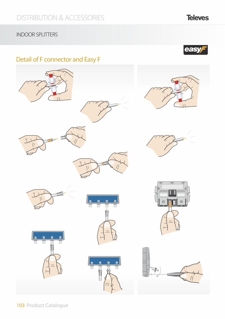
Detail of F connector and Easy F
DISTRIBUTION & ACCESSORIES
103 Product Catalogue
INDOOR SPLITTERS

DISTRIBUTION & ACCESSORIES
104 Product Catalogue
INDOOR SPLITTERS
F connector
5-1000MHz
4530 2 Ways
4532 3 Ways
4531 4 Ways
4534 6 Ways
4533 8 Ways
950-2150MHz active
7402 8 Ways active
Ref. DeSCRIPTION PRODUCT RANGE
References 4530 4532 4531 4534 4533
Band MHz 5-1000
Number of outputs 2 3 4 6 8
Through losses
VHFdB
5 7 9 10 12
UHF 5 7 9 10 12
Rejection between outputs dB 15 20 15 20 15
Type of connectors F
Dimensions mm 52x50x20 74x50x20 123x60x20
References 7402
Band MHz 950-2150
Number of outputs 8
IF gain dB 5-7.5
Rejection bet. outputs dB 12
DC bypass outputs-inputs Yes
Noise figure dB <8
Dimensions mm 141x97x24
5-2400MHz
5150 2 Ways 4/5 dB
5151 3 Ways 7/9 dB
5152 4 Ways 7.5/10 dB
5153 5 Ways 10/12 dB
7441 6 Ways 12/16 dB
7406 8 Ways 14/19 dB
5155 2 Ways all DC
5156 4 Ways all DC
5157 5 Ways all DC
5158 6 Ways all DC
5159 8 Ways all DC
References 5150 5151 5152 5153 7441 7406 5155 5156 5157 5158 5159Band MHz 5 - 2400 5 - 2400
Number of outputs 2 3 4 5 6 8 2 4 5 6 8
Through lossesMATV
dB4 7 7.5 10 12 14 4 7.5 10 10 11
FI 5 9 10 12 16 19 5 10 10 11.7 13.6
Rejection between outputsMATV
dB > 20 > 17 > 19 > 20 > 28 > 34FI
Max. output-input DC bypass A 1
4061 F type 75 ohms load DC blocked
4058 F type DC 75 ohms load
System accesories
DC bypass from the outputs to the input
Ref. 5150
DC DCDC
Ref. 5155
DC DC DC DC DC DC
ALL DC Splitters
p 4534

DISTRIBUTION & ACCESSORIES
105 Product Catalogue
INDOOR TAPS
5-2400 MHz Easy F
Ref. DeSCRIPTION PRODUCT RANGE
2 Ways
542502 2D 12 dB (Floor 1) TA
542602 2D 16 dB (Floor 2, 3) A
542702 2D 20 dB (Floor 4-6) B
542802 2D 24 dB (Floor 7-12) C
4 Ways
544402 4D 12 dB (Floor 1) TA
544502 4D 17 dB (Floor 2, 3) A
544602 4D 20 dB (Floor 4, 5) B
544702 4D 25 dB (Floor 6, 7) C
Referencias 5492 5493 5494 5610 5611Number of outputs 6 8Floor 1 2···3 4···5 1 2
Through lossesIN - OUT
C. ret.
dB
<11 <6 <6 14 4MATV 5 3 3 7 2
FI 5 3,5 4 8 5
Tap lossesIN-D1/D2/D3/D4
C. ret. <18 <20 <26 <18 <24MATV 16 20 24 16 23
FI 16 20 24 16 23
Rejection bet. tapsC. ret. >30 >30 >35 >30 >30MATV >30 >30 >30 >30 >30
FI >30 >25 >25 >20 >20
Rejection bet. tapsC. ret. >30 >40 >45 >35 >40MATV >30 >40 >45 >35 >40
FI >30 >40 >45 >35 >40Max. voltage Vdc 40Max. bypass current mA 300
References 542502 542602 542702 542802 544402 544502 544602 544702Number of outputs 2 4Floor 1 2···3 4···6 7···12 1 2···3 4···6 7···12
Through lossesIN - OUT
C. ret. <4 <1.5 <2 <1 5.5 3 2.3 1.5MATV 2.2 1.2 1.1 0.7 4.7 2.3 1.6 1.3
FI 2.4 2 1.2 0.9 5-7.5 2.3-3 2.1 1.4-3
Tap lossesIN-D1/D2
C. ret. <13 <16 <20 <24 12 17 20 25MATV 13 16 20 24 13 17 20 25
FI 12 16 20 24 15 17 22 25Rejectionoutput-tap
MATV > 32 > 27 > 35 > 42 > 33 > 32 > 33 > 35 FI > 25 > 24 > 35 > 38 > 30 > 33 > 30 > 33
Rejection bet. tapsMATV
dB> 37 > 42 > 30 > 30 > 28 > 27 > 28 > 30
FI > 31 > 34 > 22 > 23 > 21 > 20 > 22 > 25Max. bypass current mA 300
6 Ways
5492 6D 16 dB (Floor 1) TA
5493 6D 20 dB (Floor 2, 3) A
5494 6D 24 dB (Floor 4, 5) B
8 Ways
5610 8D 16 dB (Floor 1) TA
5611 8D 22 dB (Floor 2) A
The innovative easy fast F-connectorprovides the advantages of the S&Cconnector and the F-connector.
Fully shielded.
They allow an IN-OUT current bypass.
p 2W/4W
p 6W/8W

DISTRIBUTION & ACCESSORIES
106 Product Catalogue
5-2400 MHz F connector
5141 4W 12 dB
5142 4W 16 dB
5143 4W 19 dB
5144 4W 24 dB
5145 4W 28 dB
Ref. DeSCRIPTION PRODUCT RANGE
5130 12 dB
5131 15 dB
5132 18 dB
5133 23 dB
5134 27 dB
Ref. DeSCRIPTION PRODUCT RANGE
2 Ways
4 Ways
6 Ways
8 Ways
5135 18 dB
5136 20 dB
5137 24 dB
Ref. DeSCRIPTION PRODUCT RANGE
5146 18 dB
5147 20 dB
5148 23 dB
Ref. DeSCRIPTION PRODUCT RANGE
References 5135 5136 5137 5146 5147 5148Frequency range MHz 5-2400
Through losses
Ret. Path
dB
3 1.7 1.5 3 1.7 1.5VHF UHF 3.3 2 1.5 3.3 2 1.5
IF 5 4 2.5 5 4
Tap losses
Ret. Path18 20 24 18 20 23VHF
UHFIF 19 21 25 19 20 25
Rejection between taps >21Max. bypass current A 1
References 5141 5142 5143 5144 5145Frequency range MHz 5-2400
Through lossesMATV
dB
4.5 2.3 1.5 1 1IF 5 3.4 2.5 2 1.5
Tap lossesMATV 12 16 19 24 28
IF 12 16 20 24 29
Rejectionoutput-tap
MATV > 50 > 35IF > 30
Rejection bet. taps MATV dB > 25 > 20Max. bypass current A 1
References 5130 5131 5132 5133 5134 Frequency range MHz 5-2400
Through lossesMATV
dB
2.5 1.2 1.5 1 1IF 2.6 2 1.5 1.5 1
Tap losses MATV 12 15 18 23 27
IF 12 15 19 23 27
Rejectionoutput-tap
MATV > 32 > 27 > 35 > 42 > 50IF > 25 > 24 > 30 > 35 > 35
Rejection bet. tapsMATV
dB > 30IF
Max. bypass current A 1
4061 F type 75 ohms load DC blocked
4058 F type DC 75 ohms load
System accesories
INDOOR TAPS
p 5142

DISTRIBUTION & ACCESSORIES
107 Product Catalogue
INDOOR TAPS
1 Way
4516 8 dB
4517 11 dB
4518 14 dB
4519 17 dB
2 Ways
4560 4 dB terminal
4561 9 dB
4562 11 dB
4563 14 dB
4564 17 dB
4565 20 dB
4566 23 dB
4567 26 dB
4 Ways
4571 8 dB terminal
4572 11 dB
4573 14 dB
4574 17 dB
4575 20 dB
4576 23 dB
4577 26 dB
8 Ways
4578 12 dB terminal
4581 20 dB
Ref. DeSCRIPTION PRODUCT RANGE
References 1D 4516 4517 4518 4519Frequency range MHz 5-1000
Tap losses
dB
8 11 14 17
Through losses 2.4 1.5 1.5 1.3
Rejection between taps 30 33 35 37
Dimensions mm 52x50x20
References 2D 4560 4561 4562 4563 4564 4565 4566 4567Frequency range MHz 5-1000
Tap losses
dB
4.5 8 11 14 17 20 23 26
Through losses - 2.5 2.0 2.0 1.5 1.0 1.0 1.0
Rejection between taps 28 28 27 27 27 27 27 27
Dimensions mm 52x50x20
References 4D 4571 4572 4573 4574 4575 4576 4577Frequency range MHz 5-1000
Tap losses
dB
8 11 14 17 20 23 26
Through losses - 4.0 2.5 2.0 1.0 0.5 0.5
Rejection between taps 25
Dimensions mm 66x56x20
References 8D 4578 4581Frequency range MHz 5-1000
Tap lossesdB
12 20
Through losses - <2
Dimensions mm 92x56x20
5-1000 MHz F connector
This passive line for interior distribu-tion provided with F connectorsincludes taps with 1,2, 4 and 8 ways,as well as a support for wall moun-ting.
4061 F type 75 ohms load DC blocked
4058 F type DC 75 ohms load
System accesories
p 4578
p 4560p 4571

DISTRIBUTION & ACCESSORIES
108 Product Catalogue
OUTLETS
End
5226 Diplexed TV/FM-SAT
524605 Triplexed TV-R-SAT
5270 MATV (bridged)
Ref. DeSCRIPTION PRODUCT RANGE
End outlet Through outlet Female IEC connector Male IEC connector F Female
Through
5-2150 MHz
5236 20 dB + DC
5227 14 dB + DC
5228 10 dB + DC
5229 4 dB+ DC end splitter outlet
Low losses 5-862 MHz
5230 FM-TV 4 dB end outlet
5231 FM-TV BP 10 dB
5-1000 MHz
5232 FM-TV End outlet SCATV
5233 FM-TV SCATV
Ref. DeSCRIPTION PRODUCT RANGE
5442 Back box
5441 Face plate R-TV
5440 Face plate TV/FM-SAT
544302 Face plate TV-R-SAT
5275 Face plate FM-TV-SAT-RJ45
Ref. DeSCRIPTION System accessories
Ref. SymbolTap losses (dB)
BandsReturn BI Subband FM Low S BIII/DAB High S
Hyperb. UHF IF - SAT DC bypass(350mA)
Through losses loss(dB)
5-47 47-68 68-89 88-108 104-174 174-230 230-446 470-862 950-2150 2150-2400 MATV IF SATSCATV 5-1000 MHz
5232TV <1 - <1
- - - - R - 3 -
5233TV <8 7 - 7
- - 2.6 3 R - 26 -
DC pass outlets 5-2150 MHz
5229 TV/R 1 4 5 6.5 -
- -SAT 1 4 5 6.5 SAT®IN
5228 TV/R 6 7.5 10.5 13 IN®OUT
SAT®IN 3.5 5
SAT 11 8.5 9 10
5227 TV/R 10.5 13 13.5 14 IN®OUT
SAT®IN 1.2 2
SAT 10.5 13 14 14.5
5236TV/R 20 20 24 23 IN®OUT
SAT®IN 0.6 1
SAT 18 20 24 24.5Low losses 47-860 MHz
5231 TV 10 9.5 - 9.5
- - <1.3 2 R - 26 -
5230 TV/R 4.3 4.5 - 4.5
- - - -
SAT - 18 - - - End bridged
5270 TV/R <5*
- Yes - -SAT <5*
Splitters - 2 outputs
5226TV/R 0.3 0.6 -
SAT®IN - - SAT - 1.5 ± 0.2
Triple triplexed
524605TV <8 4.5
- -- -R <8 4.5
SAT - 1.5 ± 0.2 SAT®IN
* Depending on the output loadedTV response R response SAT response

DISTRIBUTION & ACCESSORIES
109 Product Catalogue
OUTLETS
Multimedia
5240 Multimedia end outlet
5247 10dB pass-through outlet
5248 15dB pass-through outlet
5249 20dB pass-through outlet
Ref. DeSCRIPTION PRODUCT RANGE
References 5240 5247 5248 5249
Frequency range (MHz) TV-RF-DATA / 110..1000-87..108-5..1000
Through losses (dB) - <2 1,5 1
Tap losses DATA (dB) <3,5 10,5 15 20
Tap losses TV (dB) <5 10 15 20
Tap losses RF (dB) <10 15 20 25
Isolation DATA-TV (dB) >70
Isolation DATA-RF (dB) >30
VSWR input (dB) >14
VSWR DATA (dB) >14
VSWR TV (dB) >10
HF- connections IEC Male/Female/F
The choice of distribution products is automati-cally produced to receive a great high-class level.This family consists in a complete product rangewhich fulfils all demands from single systems upto CATV systems.
FULLY AUTOMATED MANUFACTURING
3Easy and fast connection system for different inner conductor diameters
3Snap-in terminals for inner conductor
3Inner conductor conical guiding path for ease of connection
3Holes to release the inner conductor cable by pressing the self-retaining contact
3180º opening lateral clamp
3Class A screening
NEW Lateral Opening Clamp
Total quality in one stepClick - and-go system

DISTRIBUTION & ACCESSORIES
110 Product Catalogue
CONNECTORS
SCATV 5/8” Type
4121 5/8” cable 1/2”
4122 5/8” cable TR165
Ref. DeSCRIPTION PRODUCT RANGE
IEC Elbowed shielded
IEC Shielded
4130 Male 9.5 mm Ø
4131 Female 9.5 mm Ø
413201 Male 9.5 mm Ø pro
413301 Female 9.5 mm Ø pro
437401 Male 9.5 mm Ø pro (blister)
437501 Female 9.5 mm Ø pro (blister)
437601 M/F 9.5 mm Ø pro (blister)
Ref. DeSCRIPTION PRODUCT RANGE
The Televes connector "EASY" guarantees the maximum qua-lity in the equipments and systems connexion, providing theSHIELDING to the digital signals in the installation at issue.
The coaxial cable junction turns into an easy and fast opera-tion. Not having different pieces, makes it ideal to connecto-rize the cable in difficult locations, where the elements han-dling is a tricky task.
Simplicity and speed of assembly:
- One single screw.
- Connection always visible.
- Without curled up pieces.
- Without detachable pieces
Safe connection:
- Assures the fiability of the connection and does not
need future revisions.
- The installer will have the feeling that if something fails,
it is not the connectors fault.
Electrically perfect:
- Automat fabrication.
- Total shielding that prevents from unwanted effects in
the DTT reception.
- Perfect adaptation to the distribution network elements.
- Due to its performance and quality, it is the connectortobe used with the actual DTT and in the future HDTV.
The cover is hingedand the screw iscaptive into thecover.
The inner conductor isguided by means of a slotin a plastic top.
No loose parts that haveto be held while a connectionis being established.
One single screw for the clamping.
Jagged rows assure a perfectouter sheath clamping.
Made of Zamak, RPR* (* Spanish abbreviation forReactive Sealing Treatment)
p 413201/413301p 4130/4131
p 4122p 4121

DISTRIBUTION & ACCESSORIES
111 Product Catalogue
CONNECTORS
431001 LTE extender cord 1,5m
431002 LTE extender cord 2,5m
Ref. DeSCRIPTION PRODUCT RANGE
LTE's shielded extendercords
Shield your TV against LTE's interferencesю
Beyond the necessary adaptation of facilities and for good recep-tion of the TV for the future deployment of LTE, the weakest pointwill be the coaxial extender cord, which carries the signal from theoutlet to either the TV or the DTT adapter.The quality of this com-ponent, traditionally ignored, is now crucial and can not be leftcommited to imported products of dubious quality, "monos-hield", unshielded and without a shielding foil.
Even though they are necessary in any field, they are particularlysuitable in singular facilities as the ones for Hotel Industry. In suchinstallations, there is nothing more valuable than a quality custo-mer service: the coaxial extenders from Televés provide a televi-sion service "LTE Ready".
• They are manufactured using T200 Cable, Class A, with 75% covera•ge, high shielding and low losses.
• They feature shielded connectors Pro Easy-F class A; specificallydesigned to provide these extenders with a special shielding. Inaddition, these connectors also allow to construct extender cordswith different lengths than those supplied by means of these tworeferences.
• Suitable for cable operators' networks, which use channels that canbe affected by the LTE.
The signal generated by LTE mobile devices (signal "Uplink") or pro-ximity to TV transmitters, can affect the quality of reception either onthe TV itself or on the DTT adapter.
Only with a well shielded extension cord, as are our ref. 431001 or ref.431002, can be achieved the quality parameters of a DTT signal avoi-ding the ingress of any kind of interferent signals.

Cases for Easy F splitters and taps
545501 Face plate
4177 Black plastic case (small)
4163 Black plastic case (big)
Ref. DeSCRIPTION PRODUCT RANGE
Ref. DeSCRIPTION PRODUCT RANGE
F Type
4176 Elbow push fit (CXT&T100)
4171 Plug twist (CXT&T100)
9349 Plug twist (TR165)
4120 Plug crimp (1/2”)
4127 Plug twist (CXT 5 mm)
413401 Elbow male professional
4135 F connector T100
4104 F compress
4105 F compress
410801 F compress T200
4106 F compress
4306 F type + weatherproof over
2163 Compressing tool
Ref. DeSCRIPTION PRODUCT RANGE
p 4177
p 494501p 4087p 4058
p 4071 p 4061
p 4173
p 9349
p 4134
p 2163p 4176
p 4127p 4120p 4171
p 4006 p 4123
p 545501
p 4104
DISTRIBUTION & ACCESSORIES
112 Product Catalogue
CONNECTORS
Join connectors
4006 Coaxial joint
4173 F female - F female
Adapters
4123 5/8” - F connector
4071 DC block F connector
75 W Terminal loads
4061 F type 75 ohms load DC blocked
4058 F type DC 75 ohms load
4087 For saddle&clamp, DC blocked
SCART leads
7352 2 SCART 21 pin
HDMI/HDMI
494501 cable extender 1,5 m Black
494502 cable extender 3 m Black
494503 cable extender 5 m Black
new
Connection accessories

DISTRIBUTION & ACCESSORIES
113 Product Catalogue
CONNECTORS
References 2141 05/07 2155/03 210603 2138 02
2139 2140 213001
Model T100 CXT5 CXT 1/2´´ T200
Inner cond.Ø (mm) 1,13 1,13 0,8 1 2,7 1,20Material Cu Cu Cu Cu Cu CuResist. (W/Km) 20 20 37 23 3,2 <16
DielectricØ (mm) 4,8 4,8 3,4 4,8 11,5 5
Material PEE PEE PEE PEE PEE PEE
Overlapping shielding foil B B A B B C
BraidResist. (W/Km) 20 20 35 35 7 <12
Material Cu Cu CuAl Cu Cu Cu
Antimigration film Yes Yes No No No Yes
Petrol jelly No No No No Yes No
Outer sheath
Ø (mm) 6,6 6,6 5 6,6 15 6,9
Colour W/B/W Black White W/W/B Black W
Material PVC PE PVC PVC PE PVC
Minimum bending radio (mm) 33 33 25 33 75 33Shielding (dB) >75 >75 >75 >75 >75 >75Capacitance (pF/m) 55 55 53 55 55 55
Impedance (W) 75 75 75 75 75 75
Meters / reel (m) 100/100/250 100/250 100 100/250/100 500 100
Attenuations
Freq. (MHz)
200
dB/m
0,08 0,08 0,11 0,09 0,03 0,07
500 0,12 0,12 0,17 0,14 0,06 0,12
800 0,15 0,15 0,23 0,18 0,07 0,15
1000 0,18 0,18 0,25 0,20 0,08 0,17
1350 0,21 0,21 0,30 0,23 0,10 0,20
1750 0,24 0,24 0,34 0,27 0,11 0,23
2050 0,27 0,27 0,37 0,29 0,12 0,25
2150 0,27 0,27 0,38 0,30 0,13 0,25
2300 0,28 0,28 0,40 0,31 0,14 0,27
Cu + Fe: Copper clad steel PE: Polyethylene
Al: Aluminium PEE: Foam polyethylene
Cu: Copper LSFH: Low Smoke Free Hallogen
Overlapped foil
A Al + Polyester + Al
B Cu + Polyester
Sheath EnvironmentPVC IndoorPE OutdoorLSFH Special
Ref. DeSCRIPTION PRODUCT RANGE
Copper braid
210603 CXT5 PVC 100 m
2138/02 CXT PVC 100/250 m
2139 CXT PVC Black 100 m
2141/05/07 T100 PVC 100/100/250 m
2155/03 T100 PE 100/250 m
2140 1/2” PE 500 m
213001 T200 100 m

Ref. DeSCRIPTION PRODUCT RANGE (70% screening factor series)
214102/04/08 T100 PVC 100/250/100 m
215101 T100 LSFH 100 m
2128 /01 CXT PVC 100/250 m
2127/01/02/03/04 CXT1 PVC 100 m
215501/02 T100 PE 100/250 m
2126/01/02/03 T100 PVC 100/250/250/100 m
214901 TR165 PE 250 m
References 2126 01/02/03 214102 /04/08 214901 215101 2128/01 2127 01/02/03/04
215501/02
Inner conductorØ mm 1,12 1,13 1,63 1,12 1 1 1,13Material Cu Cu Cu Cu Cu CCS CuResistance (W/Km) 18 16 9 18 20 97 18
DielectricØ mm 4,8 4,8 7,2 4,7 4,5 4,7 4,8Material PEE PEE PEE PEE PEE PEE PEE
Overlapping Foil Material B B A B A A B
Outer conductor
Resistance (W/Km) 27 12 8 14 31 30 13Dimensions(carrier x strands x Ø mm) 16x6x0,14 16x8x0,11 16x7x0,15 16x8x0,11 16x6x0,14 16x7x0,13 16x8x0,11
Screening (%) 74 73 70 73 74 73,4 73Material Al Cu Cu Cu Al Al Cu
Antimigrating film no yes no yes no no yes
Outer SheathØ (mm) 6,9 6,6 10,1 6,6 6,5 6,7 6,6Colour W/W/B/B W/W/B black white white W/B/B/W/W black Material PVC PVC PE LSFH PVC PVC PE
Minimum bending radius (mm) 34,5 33 50,5 33 32,5 33,5 33 Shielding (dB) >75 >75 >75 >75 >75 >75 >75Impedance (W) 75 75 75 75 75 75 75Metres / reel (m) 100/250/250/100 100/250/100 250 100 100/250 100/100/250/250/500 100/250Attenuations
Frequence (MHz)
85
dB/100 m
5,35 5,40 3,59 4,85 5,82 6,38 5,07200 8,02 7,88 5,44 7,50 8,68 9,39 7,88500 13,15 12,69 8,97 12,00 14,13 15,24 12,69750 16,49 15,80 11,20 15,00 17,72 19,27 15,74800 17,06 16,32 11,59 15,60 18,33 20,00 16,33
1000 19,3 18,37 13,13 17,00 20,68 22,84 18,361350 22,76 21,62 15,48 20,50 24,27 27,50 21,641750 26,35 24,87 18,00 23,50 28,12 32,26 24,822050 28,88 27,22 19,78 25,70 30,71 35,67 27,122150 29,55 27,85 20,31 26,00 31,42 36,87 27,812300 31,54 29,15 21,12 27,00 32,75 38,50 29,47
Al : Aluminium PE: PolyethyleneCu: Copper PEE: Foam PolyethylenePVC: Polyvinyle Clorhidre LSFH: Low Smoke Free HallogenCSS: Copper Clad Steel
Overlapping foil compositionA Al + Polyester + AlB Cu + PolyesterC Cu + Polyester
Sheath Environment of usePVC IndoorPE OutdoorLSFH Special
70% screening factor series
DISTRIBUTION & ACCESSORIES
114 Product Catalogue
COAXIAL CABLE

DISTRIBUTION & ACCESSORIES
115 Product Catalogue
COAXIAL CABLE
Remark:
The PE cables (polyethylene)are used for outdoor applica-tions.
The PVC cables are used forindoor applications.
Coaxial cable stripping detailCable losses
Recommendations
30,0
25,0
20,0
15,0
10,0
5,0
0,0
5 200 400 600 800 1000 1200 1400 1600 1800 2000 2150 MHz
dB/100 m
2140
2149
2141
Coaxial cable section detail

116 Product Catalogue

Indoor receivers for terrestrial and satellite channels. Easy to use, with easy and intuitive menus.
DTH RECEIVERS

RECEIVERS
118 Product Catalogue
TERRESTRIAL TV
USB
PVR
New functions:
Teletext: Withstanded function by the own adapter, thatmakes it independent from teletext function on behalf of thetelevision set.
Subtitles: Function of special demand in professional associa-tions, as:
People with hearing deficiency.
People interested in languages and/or in programs in originalversion.
Complete EPG: More information about programming andevents.
Channel sorting: Function that is independent from the list offavourites and that allows the channel sorting at the usersease.
Less consumption: The compromise with the environmentleads the zAs to carry out, through the remote control, a realstandby time (consumption lower than 2,5W). The ecologicalzAs.
p 5124

RECEIVERS
119 Product Catalogue
TERRESTRIAL TV
General
Channels 198 (99TV + 99 Radio)
EPG yes
Through output MHz 47-862
Demodulator
Signal range COFDM, 2K, 8K
Input band MHz 174-862
Input Level dBµV 45-90
Constellations 16QAM, 64QAM
FEC 1/2, 2/3, 3/4, 5/6, 7/8
Guard interval 1/4, 1/8, 1/16, 1/32
Ouput frequency MHz 474-862
Ouput channel CH 21 - 69 (CCIR)
TV PAL B/G
Video
Input format and decod. MPEG-2 MP @ ML
Max. video rate Mbps 15
Screen format 4:3 / 16:9
Video resolution 720 x 576
Audio
Audio decoder MPEG/MusiCam Layer I & II
INPUT/OUTPUT Port
Input connector 1 x IEC (female)
Output connector 1 x IEC (male)
Serial port connection RS232C, SUB-D female 9-pins
Video output RGB 1 x SCART TV connector
Video output CVBS Analogue audio output 1 x SCART TV connector
Analogue audio output 1 x SCART TV connector
Powering
Consumption mA(V) 0.40 (12)
Consumption (Stand-by) W < 2,5
Mains voltage 220-240 Vac, 50/60 Hz
Physical characteristics
Dimensions mm 180 x 29 x 140
Weight Kg 0.3
Reference 5124
Functions:
Incorporated modulator: Configurable through the menu, withoutput in any UHF channel.
Its advantages:
Be part of a coaxial distribution network. The service tunedby the zAs can be distributed over the whole house by meansof the antenna network.
It is compatible with old television sets, without SCART,and/or with television sets from secondary houses.
It is not necessary to throw away old television sets.
High sensibility: It adapts televisions in zones of poor coverage.The tuners sensibility is higher than the one incorporated intelevisions that are compatible with DTT. Besides, it providestelesupply to activate devices (DAT HD, MRD and AmplifiersFI_MIX).
Size: Its discrete dimensions make it perfect for reduced loca-tions.
European Technology Made in Europe: From the design andmanufacturing up to the firmware, everything is made inSpain.

ZAS Satellite
Standard DVB-S / DVB-S2.
Free-to-Air channels (FTA).
Video: MPEG2 and MPEG4/H.264 compatible.
Audio: MPEG-1 (layer 1,2), Dolby Digital+, MPEG-4, AAC andHEAAC compatible.
PVR via USB 2.0. External hard disk (FAT32) or “Pen Drive”(FAT32) needed (*).
Simple and user friendly menus. First installation guided.
Advanced reproduction functions: forward, rewind, previous /next, pause, go to, etc.
“Time Shift” via USB 2.0.
Timer.
Electronic Programmes Guide (EPG) up to seven days.
Up to 3.500 programmes and up to 6 favorite lists.
VBI teletext, OSD teletext, standard subtitles and teletext subti-tles.
Parental lock.
Auto save function for last channel used.
Software Upgrading via USB 2.0.
HDMI Output (Auto, 576i, 576p, 720p, 1080i, 1080p).
Optical audio output.
Multi-video Scart output (CVBS, RGB).
Low consumption.
717501 Zas Satellite
Ref. DeSCRIPTION PRODUCT RANGE
p 717501
Tuner / LNB input
Input connector 1 "F"
Output connector 1 "F"
Input band 950-2150 MHz
LNB powering volt/mA 13-18 / 300
De-modulation QPSK (DVB-S, DVB-S2)
FEC 1/2, 2/3, 3/4, 5/6, 7/8, Auto
Digital video Compatible 15 Mbit/s Max.
Video format 4:3, 16:9
Video resolution 1080p, 1080i, 720p, 576p, 576i
Audio MPEG/MusiCam Layer I & II
Teletext DVB compatible
Flash memory 4 Mbytes
RAM memory 16 Mbytes
References 717501
Video / Audio decodification modeVideo MPEG-2Video format 4:3, 16:9Audio MPEG-1Audio modes Mono; Dual; Stereo; "Joint stereo"Output signalOutput signal mode RGB, CVBS, Analog Audio
Input connector 1 SCART
Optical HDMI (audio/video)
Powering and physical characteristicsMains voltage Vdc 12Consumption mA 325Stand-by max. mA 50Working temperature ºC 10-40Dimensions mm 280 x 165 x 43Weight Kg 1.3
RECEIVERS
120 Product Catalogue
TERRESTRIAL TV

RECEIVERS
121 Product Catalogue
SATTELLITE TV
Satellite Digital Receiver
General
Number of channels 4000
Number of channels various
Channels block yes
Teletext no
Subtittles no
Timer yes
Tuner / LNB input
Input band MHz 950 - 2150
Frequency scanning yes
Number of LNB inputs 1 "F"
Loop through signal for LNB yes
LNB powering volt/mA 13-18 / 350
DiSEqC 1.0 / 1.2 / toneburst A/B
Positioner system USALS / DiSEqC 1.2
Symbol rate 2 - 45 Msps
SAT Bands C & Ku
References 7118
Domestic unit for digital satellitechannels reception.
Audio/video signals are providedvia SCART or RCA outputs.
Compatible with both DiSEqC andUSALS positioners.
VCR RS232TVL R
Internal F1:T2AL 250V
MODEL NO: RSD 7118
220 - 240 V~50/60 Hz, 25W
Made in China
VIDEOOUT
AUDIOOUT
LNB IN
IF OUT
PO
WE
R
TV OUT ANT IN
Video / Audio decodification mode
Video MPEG-2
Video format 4:3, 16:9
Audio MPEG-1
Audio modes Mono; Dual; Stereo; "Joint stereo"
Output signal
Output signal mode (A/ V) RGB, CVBS, Audio L/R
Input connector 1 SCART
INPUT/OUTPUT Ports
RS232 1 x (9-pin D-sub)
SCARTS 2 x (TV / VCR)
RCA 3 x (video - L audio - R audio)
LNB 2 x "F" (in-out)
Powering and physical characteristics
Mains voltage 90 - 260 V, 50/60 Hz
Consumption W 15
Dimensions mm 280 x 165 x 43
Weight Kg 1.3
7118 FTA Satellite receiver w/modulator
Ref. DeSCRIPTION PRODUCT RANGE
modulator
p 7118

122 Product Catalogue

The fastest and most precise portable meter in the world within arm's reach. The H45 meter
has been designed with digital processing technology allowing Real-time sweeping and
unthinkable versatility and preciseness.
FIELD STRENGHT METERS

124 Product Catalogue

METERS AND TOOLS
125 Product Catalogue
FIELD STRENGHT METERS
The meter you are looking fordisplays and measures MPEG4 SIGNALS
FIRST HANDHELD METER WITH DIGITAL PROCESSING
The H45 meter has been designed to obtain all the informa-tion instantaneously from the signal by the development ofmathematical algorithms. Up to 20 MHz digitally capturedin less than 10 ms. That simple, yet that dramatically impor-tant and difficult to develop. Only Televes could be the firstto do it in a small Field Strength Meter.
What colour TV was to black&white, or how broadbandADSL compares to the old rotary dialling... that is what theH45 with Digital Processing is to other portable meters.
A total revolution:
- Real-Time sweeping speeds- Unprecedented preciseness - Unthinkable versatility.
Televes H45 with Digital Processing. Because revolution isnot making a smaller meter.
Revolution is making a Digital Processing meter in a smallerformat.

METERS AND TOOLS
126 Product Catalogue
FIELD STRENGHT METERS
Televes H45 is a milestone in the field strength meters world. The latest technology and high-end features in a complete range, that will neverbe outdated ,due to its capability of being upgradable at any time.
Its easy and intuitive interface , becomes the instrument in a reference for all the installers .
The Televes H45 Meters
are based on Digital Processing as the engine for the advanced features as well as the key to belightweight, fast and scalable.
3Digital processing
3Combo mode display
3Advanced spectrum analyzer
3UAL (Universal Auto Log) and Scan&Log functions
3Ergonomic design
3Compact, lightweight and user friendly
3Upgrading and Scalability
Pictures, Spectrum andMeasurements (with Quality CheckMarks) in 1 screen.Signal information is updated realtime.Everything you need regarding thesignal measurements is displayed inthe screen of the meter.
COMBO MODE DISPLAY
H45 meter
5990 H45 Compact
599001 H45 Compact Full HD
599002 H45 Compact Full HD + CI
5992 H45 Advance
599201 H45 Advance Full HD
599202 H45 Advance Full HD + CI
Optical Meter
599003 H45 Compact with Optical Receiver
599004 H45 Compact Full HD + Optical Receiver
599203 H45 Advance with Optical Receiver
599204 H45 Advance Full HD + CI + Optical Receiver
Ref. DeSCRIPTION PRODUCT RANGE
Advanced Spectrum Analyzer with awide dynamic margin, to measurespurious and very low noise levels.
ADVANCED SPECTRUM
Specific measurements for secondgeneration digital standards (DVB-S2 and DVB-T2). The LINK MARGIN isthe measurement that gives moreinformation about the quality ofthese signals.
LINK MARGIN
FI B
R
E O P T I C I NP
UT

METERS AND TOOLS
127 Product Catalogue
FIELD STRENGHT METERS
p 5990
Constellation, measurements, demo-dulation and DVB-T2 visualization.
To watch digital signals transmittedvia Fibre Optics (Full HD dependingon the options)
The Meter incorporates a slot for aConditional Access Module (CAM),which, combined with the correspon-ding smart card, allows to watchencrypted TV channels.
MPEG4 H.264: 576i, 720p, 1080i,1080p.
Combined with the triple light sourceOPS3L the H45 with optical receiver(optional) allows to check the respon-se of an optical distribution network.
The H45 Meters with Optical Receiver can measure opticalpower and attenuation aswell as all TV signal quality para-meters like (Level, V/A, C/N,BER, MER,...)
To represent the spectrum of the RFsignal transmitted via Fibre Optics.
A great help for accurate adjustmentof optical links.
Simultaneous analysis in three windows:1310, 1490 and 1550 nm.
DVB-T2 OPTION MPEG-4 OPTION
OPTICAL RECEIVER THE H45, THE METER YOU NEED TO CHECKTHE RESPONSE OF ANOPTICAL DISTRIBUTIONNETWORK
SPECTRUM ANALYZER IN OPTICAL MODE
OPTICAL ATTENUATION MEASUREMENT
SPECTRUM ANALYZERAdjustable reference levelSaturation alarmMax hold and marksNoise representationAutomatic satellite identificationReal time sweeping
AUTONOMYMore than 4 hoursSpecial Firmware for charging
managementBattery status indicator
MEASUREMENTSLevel: from -15 to 130dBµVC/N (automatic and referenced) BER and MER in QPSK, QAM and COFDMDVB-S2 - 8PSK and DVB-T2 measurements (*)Services (with their resolution) identificationEchoes
VIDEO AND AUDIO
HD digital signals: MPEG-4 or MPEG-2 (*)
SD digital signals: MPEG-2
Digital audio: AAC, EAAC, AC3 and EAC3 (*)
HSUITESoftware tool to generate reportsInstant Log functionCheck quality marks managementData Log functionGraph logger (*).
DVB-S2 HD (1080I) PARAMETERS
COMMON INTERFACE MODULECompatible with DVB-CI

METERS AND TOOLS
128 Product Catalogue
FIELD STRENGHT METERS
MODEL COMPACT ADVANCE
References 5990 599001 599002 599003 599004 5992 599201 599202 599203 599204
GEN
ERA
L CH
ARA
CTE
RIST
ICS
Digital Processing Technology
Scan & Log with Automatic Channel IdentificationTerrestrial
Satellite
U.A.L. Technology (Universal Auto Lock) DVB-T, DVB-C, DVB-S & DVB-S2
Q.A.L. (QPSK Auto Lock) Technology
Interfaces USB & SCART SD card
SW upgrading through USB port
HW & SW upgrading to the latest technology
Faster and more precise Navigation via Capative Knob Technology
Satellite Frequency Selection IF, Real RF, Channel and Memory
Measuring Units dBµV, dBmV, dBm, dBµV/m
Programmable Automatic Shut-down (1- 59 min.)
Programmable Automatic Suspend (1- 59 min.)
Languages English, German, Spanish, French, Italian, Portuguese, Russian and Polish
Menu and Measurements Presentation On-Screen-Display (OSD)
Teletext Analog and Digital
All measurements in one screen
Quality Checkmarks
Real-Time COMBO Mode(3 windows, spectrum, all measurements and video image)
Dynamic MarginTerrestrial 50 dB 60 dB
Satellite 45 dB 55 dB
OPTICAL Receiver Option 5999 Option 5999
HDMI – – – –
AN
ALY
SER
Mod
e
SPANTerrestrial
5, 10, 20, 50, 100, 200, 500 MHz and FULL
100, 200, 500 KHz; 1, 2 MHz;1, 1.5 & 2 GHz and FULL
Satellite5, 10, 20, 50, 100, 200, 500 MHz
and FULL100, 200, 500 KHz; 1, 2 MHz;
1, 1.5 & 2 GHz and FULL
RBW
Terrestrial100, 200, 800 and 3200 KHz
User selectable: NOAutomatic depending on SPAN: YES
Configurable from 300 Hz to 6.4 MHz
Satellite200, 800 & 3200 KHzUser selectable: NO
Auto based on SPAN: YES
B.E.R. Measurement in Spectrum –
Vertical Reference Level configurable, 5 & 10 dB configurable 1, 2, 5, 10 dB
Saturation Warning Signal (Vertical Reference Level colour change)
Real-time Sweep < 250 ms < 10 ms
Screen Refreshing Rate < 250 ms < 100 ms
HoldMaximumsMinimums
Marks 2 Up to 3
Spectrum ZOOM within same screen –
Visualisation of 2 Configurable Traces (max. and min.) –
Event Triggers to detect Pulsing Signals –
Represents Background Noise
Configurable Detectors for Sampling Digital Signals –
VBW Variable –
Satellite Identification according to the trace visualised
PRO
GRA
MM
ED M
easu
rem
ents
Memories 250 1000
Macros 100 macros with 250 memories each macro
Datalogs
Stored Measurements Capacity Up to 30.000
Download Datalogs into SD card –
Outlet type selection when executing automatic measurements
Clasification of Datalogs by Installation or Outlets
Instant Log
Graphs Logger –
HSu
ite P
Cap
plic
atio
ns Data Logger
Graphs Logger –
Check Quality Marks

METERS AND TOOLS
129 Product Catalogue
FIELD STRENGHT METERS
MODEL COMPACT ADVANCE
References 5990 599001 599002 599003 599004 5992 599201 599202 599203 599204
BAN
DS
Return Channel (5-47 MHz) Measurement and Demodulation of Analog Channels, DVB-T and DVB-C –
Continuous Band (without gaps) from 5 to 2500 MHz
Terrestrial (47-880 MHz) DVB-T, DVB-C, DVB-H and Analog Channels Demodulation
FM Radio (80-110 MHz) Measurements and DemodulationGSM (880-950 MHz) Measurements in Spectrum Mode –
Satellite (950-2220 MHz) Measures Analog Satellite. Measurements and Demodulation of DVB-S & DVB-S2
DVB S2HD Option
ref. 5991
DVB S2 HD Optionref. 5991
WIFI (2220-2500 MHz) Measurements in Spectrum Mode –Extended Spectrum (2500 - 3300 MHz) – Option 598902
AN
ALO
GSi
gnal
Mea
sure
men
ts
Level with Colour-coded Level Scale representing Signal StateAudible Signal according to Level and C/NV/A and C/N (without losing video visualisation) C/N 45 dB C/N 52 dBSynch Impulse: Real representation (Terrestrial)Video Line Representation (user defined, with off-set and zoom) –
Automatic C/NLine C/N –
TV Norms PAL B/G, D/K, I, SECAM B/G, D/K, L, NTSC
Measure Margin -15 to 130 dBµV
DIG
ITA
LSi
gnal
Mea
sure
men
ts
Power -15 to 130 dBµVAutomatic C/NReferenced C/N – in spectrum modeAudible signal according to Power and C/NImpulse Channel Response in COFDM (Echoes) HD Option
ref. 5991DVB S2 HD Option
ref. 5991Constellation QAM, DVB-S2 (8PSK or QPSK), COFDM (with manual carrier selection)
Packet Error Rate –
NICAM –
DVB - T2 – Option 598901
QAM
BER 9.9E - 2 to 1.0E - 8
MER > 38 dB
Att. Auto.
PWR 40 - 125 dBµV
Symbol Rate AUTO, (700 - 7200 Kbaud)
COFDM
cBER 9.9E - 2 to 1.0E-6
vBER 1.0E - 4 to 1.0E-8
MER > 35 dB
PWR 40 - 125 dBµVAuto Offset Detection
QPSK (with Q.A.L.technology)
cBER 1.0E - 2 to 1.0E - 6
vBER 1.0E - 4 to 1.0E - 8
MER
PWR 40-120 dBµV
Symbol Rate AUTO, from 1 to 45 Mbaud
Code Rate AUTO, 2/3, 3/4, 5/6, 7/8, 1/2
8PSK - DVB S2
Link Margin
HD Optionref. 5991
HD Optionref. 5991
(- 8.3) to 20 dBcBER 1.0E-2 to 1.0E-8
BCH BER 5.0E-2 to 1.0E-8MER
Att. Auto.PWR 40 - 120 dBµV
Symbol Rate AUTO, 1 - 30 Mbaud
Code Rate AUTO (supports 1/4, 1/3, 2/5, 3/5, 1/2, 2/3, 3/4, 4/5, 5/6, 8/9, 9/10)
MPE
G
Decodes Free-to-Air MPEG-2 with Standard Resolution
Decodes Free-to-Air MPEG-4 Resolution up to 1920×1080p - Full HD Option 5997Option 5997
Option 5997 Option 5997
Number of Services, Service Selected, Service AudiosNID, VPID, APID, SID (with Network Descriptor)
Video Resolution, Audio Type and LanguageHD Identification
Conditional Access Module (only MPEG-2) Option 5998 Option 5998 Option 5998 Option 5998
LNBs
Po
wer
ing Voltage, Extra burst (14 V, 19.5V to compensate cable losses) 13/18/24 V - 13 + 1/18 + 1/24 V (Extra Burst)
22 KHz toneDiSEqC and SCRMotor Control –
Batt
ery Type / Autonomy Litio-ION (more than 4 hours in Low Consumption mode)
Advanced Energy Management: Normal, Low Power and AutoBattery Status Indicator (icon and tone)

METERS AND TOOLS
130 Product Catalogue
FIELD STRENGHT METERS
Options
5991 H45 HD measurements option*
5997 H45 MPEG - 4 option (Requires option ref. 5991)
5998 H45 C.I. option (Requires options ref. 5991 and ref. 5997)
598901 H45 DVB - T2 option (Requires options ref. 5997 and ref. 5998).
H45 Advance exclusive
598902 H45 frequency range extension (5-3.300MHz) option.
H45 Advance exclusive
5999 H45 Optical Receiver option
5994 H45 Upgrade Compact to Advance (Requires option ref. 5991)
5909 Calibration
Accessories
5930 Noise generator
2340 OPS 3L Triple light source
5995 Weatherproof bag
Ref. DeSCRIPTION PRODUCT RANGE
MPEG4 H.264: 576i, 720p,1080i,1080p.
For services up to 1080p.
Compatible with all the digital audiostandards: AAC,EAAC, AC3 and EAC3.
FULL HD PICTURES
Compatible with dvb-ci.
The Meter incorporates a slot for aConditional Access Module (CAM),which, combined with the correspon-ding smart card, allows to watchencrypted TV channels.
COMMON INTERFACE MODULECOMPATIBLE WITH DVB-CI.
Analysis in three windows: 1310, 1490y 1550 nm.
It measures the optical power as wellas all TV signal quality parameters like(Level, V/A, C/N, BER, MER,...)
OPTICAL SIGNAL MEASUREMENTS
Constellation, measurements, demo-dulation and DVB-T2 visualization.
DVB-T2 OPTION
p 5930
p 2340
p 5995

The bandwidth of the coaxial cable allows to multiplex a number of services ohter than televi-
son. Coaxdata is a state-of-the-art system that converts a television coaxial network into a high
speed local network. By means of Coaxdata, sharing resources (computers, printers, an internet
connection, etc) does not need any additional cable..
COAXDATA

132 Product Catalogue

COAXDATA
133 Product Catalogue
COAXDATA
References 7689
ConnectorsEthernet interface 2 RJ45
Coaxial interface 2 F: TV + Data
Powering AC 100 - 240V (50-60 Hz)
Data Coaxial InterfaceOutput power 130 dBµV
Minimum Power spectral density -135 dBm/Hz
Output impedance 75 ohms
Bandwidth 2-30 Mhz
Return losses > 10 dB
TV Coaxial InterfaceThrough losses 2 dB
Return losses > 10 dB
Bandwidth 57 a 2150 MHz
Output impedance 75 ohms
Power/TemperatureWorking temperature (min., max.) -10ºC, 45ºC
Maximum consumption 4.6 Watts (45mA)
Firmware featuresMaximum number of slaves 253 (1012 using 4 masters)
Maximum length of data network (Coax Cable) 900 m.
Maximum length of data network (Power Line) 200 m.
Users per slave 2
Coaxdata HOMEPLUG
7689 Ethernet Hybrid Adapter 200Mbps
Ref. DeSCRIPTION
PRODUCT RANGE
The existing infrastructures such as hotels, resi-dential homes, schools and hospitals can facewith ref. 7689 the increasing number of internet-users, offering them an access to the net fromtheir own rooms.
In those cases where the existent infrastructure iscoaxial (i.e hotels), sharing the system to offer TVDigital Broadcast services (QAM, COFDM) and IPservices (IPTV, VoD, Internet, VoIP) at a time, is agreat choice.
The new Ethernet Hybrid Adapter 200Mbpsbrings advantages to the installations, thanks toseveral improvements in design, as well as infunctionality.
Possible coverage when big number of users, by means of mastersmultiplexation over the same frequency band.
85 dB
85 dB 85 dB
85 dB 85 dB
85 dB
85 dB
85 dB
85 dB
85 dB
85 dB
85 dB 85 dB
85 dB 85 dB
85 dB
85 dB
85 dB
85 dB
85 dB
Home Networking: multipoint-to-multipoint
253 Slaves per Master
Up to 254 Devices LAN
MxU: point-to-multipoint
Slaves Slaves Slaves Slaves
Master
p 7689

COAXDATA
134 Product Catalogue
COAXDATA
CoaxManager Software tool allows setting the installation para-meters. Ad-hoc software development option i.e, Managementand Invoicing applications.
• Networking or MxU.
• Private networks (encryption).
• QoS parameters configuration.
• MACs limitation per Slave.
• IGMP configuration.
• Status link information detailed, i.e SNR attenuation and tone-map list; allowing to get an itemized view of the installation per-formance.
Coax Link Status
Tricolor LED (green/orange/red) will be iluminated if connectivitywith another element in the network is possible.
120 Mbps < Throghput < 150 Mbps
70 Mbps < Throghput < 120 Mbps
0 Mbps < Throghput < 80 Mbps
LEDs indicators of the channel quality

COAXDATA
135 Product Catalogue
COAXDATA
ADAPTER
Internet
Ref. 7654
MxUMaster
MxUSlave
MxUSlave
MxUSlave
MxUSlave
MxUSlave
MxUSlave
MxUSlave
MxUSlave
ADAPTER
Internet
Ref. 7654
MxUMaster
MxUSlave
MxUSlave
MxUSlave
MxUSlave
MxUSlave
MxUSlave
MxUSlave
MxUSlave
T Y P I C A L A P L I C A T I O N
T Y P I C A L A P L I C A T I O N
Home Networking
MXU

COAXDATA
136 Product Catalogue
COAXDATA
HybridConectivity
ADAPTER
MasterRef. 7654
Slave Slave
Ref. 7654
MasterRef. 7654
Slave Slave
Ref. 7654
Network I
Network II
HybridConectivity
HybridConectivity
HybridConectivity
OnlyCoaxial
OnlyCoaxial
HybridConectivity
Coaxial NetworkPLC Network
HybridConectivity
ADAPTER
MasterRef. 7654
Slave Slave
Ref. 7654
MasterRef. 7654
Slave Slave
Ref. 7654
Network I
Network II
HybridConectivity
HybridConectivity
HybridConectivity
OnlyCoaxial
OnlyCoaxial
HybridConectivity
Coaxial NetworkPLC Network
T Y P I C A L A P L I C A T I O N
T Y P I C A L A P L I C A T I O N
2 Independent Networks
Using PLC

Complete range of product for domestic use.
HOME ACCESSORIES

138 Product Catalogue

7167 Digidom AV 5.8 GHz (Trans.+Receiver)
7307 Digidom AV (Trans.+Receiver)
7604 Digidom AV (Receiver)
7237 Digidom I/R disc shape (Trans.+Receiver)
7219 Digidom IR disc shape (Transmitter)
Ref. DeSCRIPTION PRODUCT RANGE
A/V and infrared transmitters
References 7167Transmitter (TX)
Channel / Frequency (Nº / MHz)
1 / 5733 5 / 5809
2 / 5752 6 / 5828
3 / 5771 7 / 5847
4 / 5790 8 / 5866
Output level dBm 10
Video Input LevelVpp
1
Audio Input Level 1
Video Input Impedanceohm
75
Audio Input Impedance 600
Supply Voltage Vdc, 300 mA) 9
Power Consumption mA 150
Dimension mm 129 x 113 x 36
Receiver (RX)
Output Level A/V Vpp 1
Receiver Sensitivity dBm -85
Supply Voltage Vdc, 300 mA) 9
Power Consumption mA 270
Single-Channel IR Transmission Frequency MHz 433,99
Dimension mm 129 x 113 x 36
References 7237/7219 7307/7604RCU Transmission band
MHz434 400
Video transmission band - 2400
Video input signal Vpp - 1
Modulation AM FM
No. of channels 1 4
HOME ACCESSORIES
139 Product Catalogue
DIGIDOM
p 7237
p 7167
p 7307
new

HOME ACCESSORIES
140 Product Catalogue
DIGIDOM
2347
10
UHF1
FM
Ref. 5328
230V50/60Hz
MATV
VHF Ref. 5435
Ref. 5437
5514
5514
2347
10 0
7
1 2 3
T Y P I C A L A P P L I C A T I O N
7605 IR extensor with coaxial link (Trasmitter + Receiver)
7606 IR extensor with coaxial link (Receiver)
Ref. DeSCRIPTION PRODUCT RANGE
References 7605 TR+IROutput frequency KHz 36 (RC5)Sensitivity dBm < -60Consumption
mA12 (12Vdc)
Output powering 30 (12Vdc)Through losses dB 0,5 (5-862 Mhz)
References 7606 IRModulation frequency MHz 14,7 MHzOutput level dBm > - 10Powering mA 9-12 (9-12Vdc)Through losses dB 0,5 (5-862 Mhz)Harmonic level dBc -45
A/V and infra-red transmitters
• IR Remote control extensor, using coaxial cable link.
• Interference free.
p 7605

HOME ACCESSORIES
141 Product Catalogue
DOMESTIC MODULATOR
1
2
3
Push-buttons instead of rotating selectors.
Interface with the user via displays
Output level regulation to avoid interferences with other channels inthe installations
5-2150 Mhz frequency range, IF included
DC bypass Input-Ouput.
Small size
IN R
F
5514
MATV
OU
T R
F +
1 C
H
MATV+1 CH (IRD)
IRD
(1)
TEST ON
TESTAUTO
(normal)
Audio
Video
T Y P I C A L A P P L I C A T I O N
Domestic modulators
5858 UHF/VHF Modulator
Ref. DeSCRIPTION PRODUCT RANGE
References 5858
Modulator
Standard PAL B/G, B Australia, PAL I, K CCIR, M-N, SECAM L, D OIRT, D-K PAL
Channels VHF (Pal B/G) BS (S01-S10), BIII (C5-C12), BS (S11-S29)
Channels UHF Ch 21- 69
Output level RF dBµV 85-90
Attenuation dB 15
Audio Carrier MHz 5,5MHz (Pal B/G)
Modulation Depth % 85
Video input level W 1Vpp s/75
Thru-input
Frequency range MHz 5-2150
AttenuationdB
2 typ.
Return losses 10 typ.
Powering
Mains voltage 196-264V~ 50-60Hz
Total consumption (I máx) A 0,026
DC bypass mA 300 máx.
p 5858

142 Product Catalogue

TECHNICAL DATA

TECHNICAL DATA
144 Product Catalogue
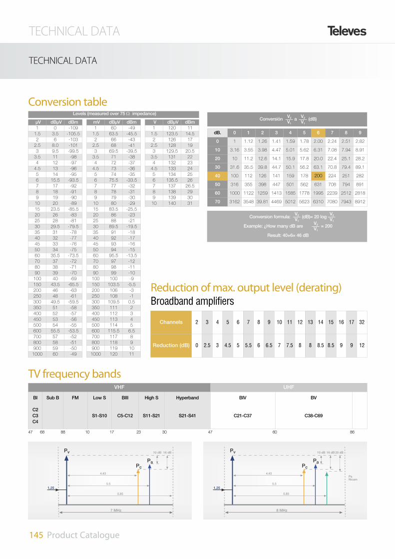
Conversion table
TV frequency bands
Reduction of max. output level (derating)Broadband amplifiers
µV dBµV dBm1 0 -1091.5 3.5 -105.52 6 -1032.5 8.0 -1013 9.5 -99.53.5 11 -984 12 -974.5 13 -965 14 -956 15.5 -93.57 17 -928 18 -919 19 -9010 20 -8915 23.5 -85.520 26 -8325 28 -8130 29.5 -79.535 31 -7840 32 -7745 33 -7650 34 -7560 35.5 -73.570 37 -7280 38 -7190 39 -70100 40 -69150 43.5 -65.5200 46 -63250 48 -61300 49.5 -59.5350 51 -58400 52 -57450 53 -56500 54 -55600 55.5 -53.5700 57 -52800 58 -51900 59 -501000 60 -49
mV dBµV dBm1 60 -491.5 63.5 -45.52 66 -432.5 68 -413 69.5 -39.53.5 71 -384 72 -374.5 73 -365 74 -356 75.5 -33.57 77 -328 78 -319 79 -3010 80 -2915 83.5 -25.520 86 -2325 88 -2130 89.5 -19.535 91 -1840 92 -1745 93 -1650 94 -1560 95.5 -13.570 97 -1280 98 -1190 99 -10100 100 -9150 103.5 -5.5200 106 -3250 108 -1300 109.5 0.5350 111 2400 112 3450 113 4500 114 5600 115.5 6.5700 117 8800 118 9900 119 101000 120 11
V dBµV dBm1 120 111.5 123.5 14.52 126 172.5 128 193 129.5 20.53.5 131 224 132 234.5 133 245 134 256 135.5 267 137 26.58 138 299 139 3010 140 31
dB. 0 1 2 3 4 5 6 7 8 9
0 1 1.12 1.26 1.41 1.59 1.78 2.00 2.24 2.51 2.82
10 3.16 3.55 3.98 4.47 5.01 5.62 6.31 7.08 7.94 8.91
20 10 11.2 12.6 14.1 15.9 17.8 20.0 22.4 25.1 28.2
30 31.6 35.5 39.8 44.7 50.1 56.2 63.1 70.8 79.4 89.1
40 100 112 126 141 159 178 200 224 251 282
50 316 355 398 447 501 562 631 708 794 891
60 1000 1122 1259 1413 1585 1778 1995 2239 2512 2818
70 3162 3548 39.81 4469 5012 5623 6310 7080 7943 8912
Levels (measured over 75 W impedance)Conversión a (dB)V2
V1V2V1
Conversion formula: (dB)= 20 log
Example: ¿How many dB are = 200
Result: 40+6= 46 dB
V2V1
V2V1
V2V1
Channels 2 3 4 5 6 7 8 9 10 11 12 13 14 15 16 17 32
Reduction (dB) 0 2.5 3 4.5 5 5.5 6 6.5 7 7.5 8 8 8.5 8.5 9 9 12
VHF UHF
BI
C2C3C4
Sub B FM Low S
S1-S10
BIII
C5-C12
High S
S11-S21
Hyperband
S21-S41
BIV
C21-C37
BV
C38-C69
16 dB
1,25
7 MHz
10 dB
5.85
5.5
4.43
Pv
Pc
Pa
16 dB
1,25
8 MHz
10 dB
5.85
5.5
4.43
Pv
Pc
Pa
20 dB
PaNicam
47 68 88 10 17 23 30 47 60 86
TECHNICAL DATA
145 Product Catalogue
TECHNICAL DATA

TECHNICAL DATA
146 Product Catalogue
TECHNICAL DATA
Radio frequency standardsTV
Bands Ch.
FrequencyChannel(MHz)
Videocarrier(MHz)
Audiocarrier(MHz)
H Standard (Australia)
IV
H28 526-533 527,25 532,75
H29 533-540 534,25 539,75
H30 540-547 541,25 546,75
H31 547-554 548,25 553,75
H32 554-561 555,25 560,75
H33 561-568 562,25 567,75
H34 568-575 569,25 574,75
H35 575-582 576,25 581,75
H36 582-589 583,25 588,75
H37 589-596 590,25 595,75
H38 596-603 597,25 602,75
V
H39 603-610 604,25 609,75
H40 610-617 611,25 616,75
H41 617-624 618,25 623,75
H42 624-631 625,25 630,75
H43 631-638 632,25 637,75
H44 638-645 639,25 644,75
H45 645-652 646,25 651,75
H46 652-659 653,25 658,75
H47 659-666 660,25 665,75
H48 666-673 667,25 672,75
H49 673-680 674,25 679,75
H50 680-687 681,25 686,75
H51 687-694 688,25 693,75
H52 694-701 695,25 700,75
H53 701-708 702,25 707,75
H54 708-715 709,25 714,75
H55 715-722 716,25 721,75
H56 722-729 723,25 728,75
H57 729-736 730,25 735,75
H58 736-743 737,25 742,75
H59 743-750 744,25 749,75
H60 750-757 751,25 756,75
H61 757-764 758,25 763,75
H62 764-771 765,25 770,75
H63 771-778 772,25 777,75
H64 778-785 779,25 784,75
H65 785-792 786,25 791,75
H66 792-799 793,25 798,75
H67 799-806 800,25 805,75
H68 806-813 807,25 812,75
H69 813-820 814,25 819,75
TVBands
Ch.FrequencyChannel(MHz)
Videocarrier(MHz)
Audiocarrier(MHz)
I Standard (Great Britain -South Africa)
III
I4 174-182 175,25 181,25
I5 182-190 183,25 189,25
I6 190-198 191,25 197,25
I7 198-206 199,25 205,25
I8 206-214 207,25 213,25
I9 214-222 215,25 221,25
I10 222-230 223,25 229,25
I11 230-238 231,25 237,25
I(12) 238-246
I13 246-254 247,43 253,43
TVBands
Ch.FrequencyChannel(MHz)
Videocarrier(MHz)
Audiocarrier(MHz)
B Standard (Italy)
IA 52,5-59,5 53,75 59,25
B 61-68 62,25 67,75
II C 81-88 82,25 87,75
III
D 174-181 175,25 180,75
E 182,5-189,5 183,75 189,25
F 191-198 192,25 197,75
G 200-207 201,25 206,75
H 209-216 210,25 215,75
H1 216-223 217,25 222,75
H2 223-230 224,25 229,75
TVBands
Ch.FrequencyChannel(MHz)
Videocarrier(MHz)
Audiocarrier(MHz)
D Standard - OIRT
I
R1 48,5 - 56,5 49,75 56,25
R2 58 - 66 59,25 65,75
R3 76 - 84 77,25 83,75
IIR4 84- 92 85,25 91,75
R5 92-100 93,25 99,75
III
R6 174-182 175,25 181,75
R7 182-190 183,25 189,75
R8 190-198 191,25 197,75
R9 198-206 199,25 205,75
R10 206-214 207,25 213,75
R11 214-222 215,25 221,75
R12 222-230 223,25 229,75
TVBands
Ch.FrequencyChannel(MHz)
Videocarrier(MHz)
Audiocarrier(MHz)
I Standard (Ireland)
I
A-1 44,5-52,5 45,75 51,75
B-1 52,5-60,5 53,75 59,75
C-1 60,5-68,5 61,75 67,75
III
D-1 174-182 175,25 181,25
E-1 182-190 183,25 189,25
F-1 190-198 191,25 197,25
G-1 198-206 199,25 205,25
H-1 206-214 207,25 213,25
I-1 214-222 215,25 221,25
TVBands
Ch.FrequencyChannel(MHz)
Videocarrier(MHz)
Audiocarrier(MHz)
K Standard
III
K4 174-182 175,25 181,75
K5 182-190 183,25 189,75
K6 190-198 191,25 197,75
K7 198-206 199,25 205,75
K8 206-214 207,25 213,75
K9 214-222 215,25 221,75
TVBands
Ch.FrequencyChannel(MHz)
Videocarrier(MHz)
Audiocarrier Hz)
L Standard (France)
III
L05 174,75-182,75 176,00 182,50
L06 182,75-190,75 184,00 190,50
L07 190,75-198,75 192,00 198,50
L08 198,75-206,75 200,00 206,50
L09 206,75-214,75 208,00 214,50
L10 214,75-222,75 216,00 222,50

TECHNICAL DATA
147 Product Catalogue
TECHNICAL DATA
TV StandardsCountry VHF UHF Colour System
Algeria B H PAL
Argentina N N PAL
Australia B H PAL
Austria B G PAL
Bahrain B G PAL
Belgium B H PAL
Bulgaria D K SECAM
China D K PAL
Cyprus B G PAL
Croatia B G PAL
Czechoslovakia D K SECAM
Denmark B G PAL
Egypt B G, H SECAM
Finland B G PAL
France EIL L SECAM
Germany B G PAL
Gibraltar B H PAL
Great Britain I I PAL
Greece B G SECAM
Holland B G PAL
Hong Kong (A)I I PAL
Hungary D K SECAM
Iceland B G PAL
India B - PAL
lndonesia B - PAL
lran B G SECAM
Iraq B - SECAM
lreland I I PAL
Israel B G PAL
Italy B G PAL
Japan M M NTSC
Jordan B G PAL
Korea (Rep.) M - NTSC
Kuwait B G PAL
Country VHF UHF Colour System
Lebanon B G SECAM
Libya B H PAL
Luxemburg C L PAL/SECAM
Malta B H PAL
Malaysia B G PAL
Mexico M M NTSC
Monaco E L SECAM
Morocco B H SECAM
Nigeria B G PAL
Norway B G PAL
Oman Sultanate B G PAL
Pakistan B - PAL
Philippines M M NTSC
Poland D K PAL
Portugal B G PAL
Qatar B - PAL
Romania B G PAL
Russia D K SECAM
Saudi Arabia B G PAL/SECAM
Singapore B G PAL
Slovenia B G PAL
Spain B G PAL
Sri Lanka B/H - PAL
South Africa I I PAL
Sweden B G PAL
Switzerland B G PAL
Syrian Arab. Rep. B H SECAM
Thailand B R PAL
Tunisia B G SECAM
Turkey B G PAL
U.A.E. B G PAL
U.S.A. M M NTSC
Yemen P.D. R. B - PAL
TV standards
StandardB/GCCIR
D/KOIRT
HBelgium
IUK
K1(1)
FOPTA(5)
LFrance
MFCC
N SouthAmerica
Frequency band VHF/UHF UHF VHF/UHF
Number of lines 625 525 625
Field frequency Hz
50 60 50
Line frequency 15625 15750 15625
Video bandwidth
MHz
5 6 5 5.5 6 4.2
RF channel bandwidth 7/8 8 6
Video - audio(2) spacing +5.5/5.74/5.85 +6.5 +5.5 +6/6.552 +6.5 ±6.5 +4.5
Vestigial Side Band 0.75 1.25 0.75
Spacing between the left edge of thechannel and the video carrier
+1.25
RF sync level % 100 <6 100
Picture modulation C3F negative C3F positive C3F negative
Sound modulation F3E / F3EH(2) F3E A3E F3E
Frequency modulation KHz ±50 - ±25
A/V carrier ratio10:1 to 20:1(4)
20:1:0.2(2)10:1 to 5:1 5:1 ato10:1 5:1 10:1 10:1 to 5:1(4) 10:1 a 5:1
(1) Also known as K’ / (2) For dual audio or stereo, the second value for second carrier / (3) In Germany since April 1976(4) 6.7:1 y 2,9:1 in Japan / (5) Group of territories represented by the French Overseas Post and Telecommunications Agency (FOPTA)

TECHNICAL DATA
148 Product Catalogue
TECHNICAL DATA
Channel - Frequency TablesBands
Channel
FrequencyChannel (MHz)
Video carrier(MHz)
Audio carrier(MHz)
Subcarriercolour (MHz)
Channels distribution according to CCIR (B Standard +G Europe)
I
2 47···54 48.25 53.75 52.68
3 54···61 55.25 60.75 59.68
4 61···68 62.25 67.75 66.68
Sub. Band
L1 68···75 69.25 74.75 73.18
L2 75···82 76.25 81.75 80.25
L3 82···89 83.25 88.75 87.32
II FM 88···108
S Low
Band
S1 104···111 105.25 110.75 109.68
S2 111···118 112.25 117.75 116.68
S3 118···125 119.25 124.75 123.68
S4 125···132 126.25 131.75 130.68
S5 132···139 133.25 138.75 137.68
S6 139···146 140.25 145.75 144.68
S7 146···153 147.25 152.75 158.68
S8 153···160 154.25 159.75 158.68
S9 160···167 161.25 166.75 165.68
S10 167···174 168.25 173.75 172.68
BIII
5 174···181 175.25 180.75 179.68
6 181···188 182.25 187.75 186.68
7 188···195 189.25 194.75 193.68
8 195···202 196.25 201.75 200.68
9 202···209 203.25 208.75 207.68
10 209···216 210.25 215.75 214.68
11 216···223 217.25 222.75 221.68
12 223···230 224.25 229.75 228.68
S High
Band
S11 230···237 231.25 236.75 235.68
S12 237···244 238.25 243.75 242.68
S13 244···251 245.25 250.75 249.68
S14 251···258 252.25 257.75 256.68
S15 258···265 259.25 264.75 263.68
S16 265···272 266.25 271.75 270.68
S17 272···279 273.25 278.75 277.68
S18 279···286 280.25 285.75 284.68
S19 286···293 287.25 292.75 291.68
S20 193···300 294.25 299.75 298.68
Hyperband
S21 302···310 303.25 308.75 307.68
S22 310···318 311.25 316.75 315.68
S23 318···326 319.25 324.75 320.68
S24 326···324 327.25 332.75 331.68
S25 334···342 335.25 340.75 339.68
S26 342···350 343.25 348.75 347.68
S27 350···358 351.25 356.75 355.68
S28 358···366 359.25 364.75 363.68
S29 366···374 367.25 372.75 371.68
S30 374···382 375.25 380.75 379.68
S31 382···390 383.25 388.75 387.68
S32 390···398 391.25 396.75 395.68
S33 398···406 399.25 404.75 403.68
S34 406···414 407.25 412.75 411.68
S35 414···422 415.25 420.75 419.68
S36 422···430 423.25 428.25 427.68
S37 430···438 431.25 436.75 435.68
S38 438···446 439.25 444.75 443.68
Bands Channel
FrequencyChannel (MHz)
Video carrier(MHz)
Audio carrier(MHz)
Subcarriercolour (MHz)
Channels distribution according to CCIR (B Standard +G Europe)
IV
21 470···478 471.25 476.75 475.68
22 478···486 479.25 484.75 483.68
23 486···494 487.25 492.75 491.68
24 494···502 495.25 500.75 499.68
25 502···510 503.25 508.75 507.68
26 510···518 511.25 516.75 515.68
27 518···526 519.25 524.75 523.68
28 526···534 527.25 532.75 531.68
29 534···542 535.25 540.75 539.68
30 542···500 543.25 548.75 547.68
31 550···558 551.25 556.75 555.68
32 558···566 559.25 564.75 563.68
33 566···574 567.25 572.75 571.68
34 574···582 575.25 580.75 579.68
35 582···590 583.25 588.75 587.68
36 590···598 591.25 596.75 595.68
37 598···606 599.25 604.75 603.68
V
38 606···614 607.25 612.75 611.68
39 614···622 615.25 620.75 619.68
40 622···630 623.25 628.75 627.68
41 630···638 631.25 636.75 635.68
42 638···646 639.25 644.75 643.68
43 646···654 647.25 652.75 651.68
44 654···662 655.25 660.75 659.68
45 662···670 663.25 668.75 667.68
46 670···678 671.25 676.75 675.68
47 678···686 679.25 684.75 683.68
48 686···694 687.25 692.75 691.68
49 694···702 695.25 700.75 699.68
50 702···710 703.25 708.75 707.68
51 710···718 711.25 716.75 715.68
52 718···726 719.25 724.75 723.68
53 726···734 727.25 732.75 731.68
54 734···742 735.25 740.75 739.68
55 742···750 743.25 748.75 747.68
56 750···758 751.25 756.75 755.68
57 758···766 759.25 764.75 763.68
58 766···774 767.25 772.75 771.68
59 774···782 775.25 780.75 779.68
60 782···790 783.25 788.75 787.68
61 790···798 791.25 796.75 795.68
62 798···806 799.25 804.75 803.68
63 806···814 807.25 812.75 811.68
64 814···822 815.25 820.75 819.68
65 822···830 823.25 828.75 827.68
66 830···838 831.25 836.75 835.68
67 838···846 839.25 844.75 843.68
68 846···854 847.25 582.75 851.68
69 854···862 855.25 860.75 859.68

149 Product Catalogue
GLOSSARY OF MEASUREMENTS
GAIN (dB):
This is the difference between the outputpower of an amplifier with the characteris-tic impedance (75 W) and the input power.(Fig.1)
FREQUENCY RESPONSE:
The variation in amplitude within a certainband or channel.
FLATNESS (dB): The difference betweenthe maximum and minimum gain in a cer-tain band or channel.
NOISE FIGURE:
The ratio of the actual noise power genera-ted at the output of an amplifier to thatwhich would be generated in an ideal resis-tor. The lower the noise figure, the betterthe performance.
The noise figure is expressed in (dB):NF=10 log F.
MAXIMUM OUTPUT LEVEL (dBµV).:
Single channel amplifiers:
EN50083-5 standard
Intermodulation distance= 54 dB (Fig. 2)
PAL broadband amplifiers:
DIN45004B standard
Intermodulation distance= 60 dB (Fig.3)
IF Amplifier:
DIN VDE 0855/12 standard
Intermodulation distance= 35 dB (Fig.4)
DAB Amplifier:
Intermodulation distance= 50 dB (2channeles de 4 MHz) (Fig.5)
FM Amplifier:
UNE 523/79 standard
Intermodulation distance= 54 dB (Fig.3)
REJECTION BETWEEN INPUTS/OUTPUTS (dB): The band attenuation between inputs/out-puts.
ADJACENT CHANNEL REJECTION (dB):The difference between the minimum gainin the channel and the maximum gain(minimum attenuation) in the adjacentchannel. The adjacent channel in UHF isC±2 and in VHF is C±1).
BAND REJECTION (dB):
The difference between the minimum gainin the amplified band and the maximumattenuation in the rejected band.
(Fig.6 BIII rejection of UHF)
(Fig.7 UHF rejection of BIII)
(Fig.8 rejection of FM)
AGC RANGE (dB):
The difference between the maximum andminimum signal that is necessary for asystem with AGC to keep a constant out-put.
THROUGH LOSSES (dB):
The attenuation that is undergone by signalin a specific band between the input andoutput of a device.
SPURIOUS (dBc):
The difference in levels between the chan-nel carrier created by a modulator or con-versor and the lower side band or localoscillator. This only applies when there is abroadband channel.
Televés S.A. reserves the right, without prior notice, to discontinue products or to make design changes as part of its continuos programme of product improvement.The information contained in this catalogue was to be best Televés’ knowledge, correct at the time of publication.Televés will not accept responsability for damage, injury, loss or expense resulting from any error or omission.
OBSERVATIONS
In general, the VHF band covers the following frequency ranges:
• For MATV: BI, FM, BSMID, BIII: 47···230 MHz.
• For SMATV & CATV: BI, FM, BSMID, BIII, BSUPP, BS HYPER: 47···446 MHz.
• In devices where FM rejection is not specified, this band is either amplified or combined
• Rejection of 27 (MHz) or FM does not mean that the band is not affected by the said bads as they can ingress into the system through thedistribution network.
• All Televés headends are in compliance with the CE regulations.
Working temperature
The optimum temperature to get thebest performance from the electronicequipment is between -10 and 45 °C.
(Unless otherwise specified)
t
F
t
F
t
F
Time domain Frequency domain
C/N Ratio(60 dB)
C/N Ratio(45 dB)
C/N Ratio(35 dB)
Noise level
Noise level
Noise level
Signal noise representation

150 Product Catalogue
52 dB
7 MHz
5,5 MHz
54 dB
127 dBµV
60 dB/54 FM
109 dBµV2MHz
6 dB
1140,01090,01040,0990,0940,040,0
50,0
60,0
70,0
80,0
90,0
100,0
110,0
120,0
130,0
35 dBMarker
218.00 MHz98.23 dBmV
1
3
2
Center 224 MHz Span 50 MHz
98.23 dBmVPeak Log 10 dB/Ref. 108 dBmV
Res. BW 100 KHz Sweep 2.083 sVBW 300 Kz
Atten 25 dBMkr3 218.00 MHz
BI FM BIIIBI BIII UHF
51,5 dB
BI BIII UHF
39 dB
Rechazo
Rechazo
21 dBRechazo
Fig. 1: Gain curve of a monochannel amplifier
Fig. 6 BIII to UHF rejection Fig. 7 UHF to BIII rejection Fig. 8 BI to FM rejection
Fig. 2: Max. output volt. measurement for a monochannel amp.
Fig. 3: Max. output volt. measurement for a wide band amp.
Fig. 4: Max. output volt. measurement for a IF amplifier Fig. 5: Max. output volt. measurement for a DAB amp.
GLOSSARY OF MEASUREMENTS

151 Product Catalogue
GLOSSARY OF MEASUREMENTS
Carrier-Noise ratio C/N
The carrier-to-noise ratio is defined asthe ratio between the video carriersignal level and the RMS noise level.The ratio is expressed in decibels.The threshold of perceptibility of noiseon a TV receiver occurs at a C/N ratioapproximately 45 dB. Mathematically,for one amplifier it is calculated thisway:
C/N1 (dB) = VO - (Nt + NF + G)
VO : Output levelNt: Thermal noise (depends of the con-sidered bandwidth)NF: Noise figure of the amplifierG: Gain
Carrier-to-Cross Modulation RatioC/XMOD
It is defined as the third order distor-tion which causes the modulation ofone signal carrier to modulate anothersignal carrier.
The threshold of perceptibility of thisratio on a TV screen is less than 40dB, so the C/X ratio is not the limitingfactor in the design of most systemsand is, therefore, below the thresholdin system designs.
a) XMOD for 1 amplifier
XMOD=XMODref+2·(Noutput- Nref.)
b) XMOD for N identical amplifiers
XMODNamp= XMOD1amp - 20 logN
c) XMOD for N amplifiers with dife-rents XMOD
XMODN amps=- 20 log [10-XMOD1/20 + 10-
XMOD2/20 + ... + 10-XMODN/20 ]
Carrier-to-Third Order
Intermodulation Ratio C/IMD
Third-order intermodulation is thesimultaneous pulse of 2 or 3 signalcarriers to produce a spurious carrier,caused by the third-order distortioncharacteristic of the amplifier.This type of third-order distortion isgenerally the limiting factor in the out-put capability of an amplifier. Thefollowing is a list of the parametersthat one must be aware of when spe-cifying composite triple beat:
1. Number of Channels.- The numberof triple beats per channel increasesexponentially as the number of chan-nels increases.
2. Levels.- Because triple beat is athird-order distortion, the distortion
will increase in output level. If theamplifier operates with a tilt, the dis-tortion will also be affected. A tiltedoutput will give better improvement inthe carrier-to-distortion ratio over a flatoutput.
a) CTB for 1 amplifier
CTB=CTBref+2·(Noutput - Nref.)
b) CTB for N identical amplifiers
CTBN = CTB1 + 20 logN
c) CTB for N amplifiers with diferentsCTB
CTBtotal=-20 log [ 10-CTB1/20 + 10--CTB2/20 + ... + 10-CTBN/20 ]
Carrier to Second-Order Inter mo du -lation Ratio (CSO)
It is the simultaneous pulse, or bea-ting together, of 2 signal carriersbecause of the second-order distor-tion characteristics of the amplifier.
a) CSO (dB) for 1 amplifier
CSO (dB) = CSOref + (Nout - Nref.)
b) For N identical amplifiers.
CSO (dB) = CSO1 amp - 15 logN
c) CSO for N amplifiers with diferentsCSO
CSOtotal = -15 log [ 10-CTB1/15 +10CTB2/15 + ... + 10-CTBN/15 ]
System calculations example
We would like to know the CTBresulting of the use of 5 amplifiers ref.4511 in cascade, with a tilt of 8 dB.
Data:
From the technical specifications ofthe amplifier ref. 4511, we know that:CTB = 60 @ 117 dBµV (for plain out-put, without tilt)
As we will install 5 amplifiers in cas-cade, with a tilt of 8 dB, we will recal-culate the CTB for a medium value ofthe Output level:- Output level for C69: 117dBµV- Output level for C2: 109dBµV
Step 1
Calculate the specification for a newreference level of 113 dBµV, which isthe medium value of the tilt(109+8/2=113)
Because the new output level is lower(117 vs. 113 dBµV), it will improve itsvalue.
General formula:
CTB=CTBref + 2·(Noutput - Nref.)
We extract CTBref:
CTBref = CTB + (Nref.- Noutput)
Known data:
CTB117dBµV = 60 dBcReference level: 117dBµVOutput level: 113 dBµV
Then:
CTB113dBµV=60 dB+2·(117-113)dBµV = 60+2·4= 60+8=68 dBc
Step 2
Make the calculation for the cascadeof 5 amplifiers with a tilt of 8 dB, con-sidering a new specification of CTB =
68dBc @ 113 dBuV (now it is consi-dered as a plain response).
General formula for N amplifiers incascade:
CTBN = CTB1 - 20 logN
In this case:
N =5 y CTB1amp = 68 dBc
Step 3
Substituting values:
CTB5 = 68 - 20 log5
Already calculated values for thecorrection factor are shown in thetable below.
CTB5= 68-20 log5 = 68-13,98= 54,02 dBc
SYSTEM CALCULATIONS AMPLIFIER CASCADE FACTOR
Cascade (N)C/N + SSO
10*LOG (N)CSO
15*LOG (N)CTB & XMOD20*LOG (N)
2 3,01 4,52 6,02
3 4,77 7,16 9,54
4 6,02 9,03 12,04
5 6,99 10,48 13,98
6 7,78 11,67 15,56
7 8,45 12,68 16,90
8 9,03 13,55 18,06
9 9,54 14,31 19,08
10 10,00 15,00 20,00
11 10,41 15,62 20,83
12 10,79 16,19 21,58
13 11,14 16,71 22,28
14 11,46 17,19 22,92
15 11,76 17,64 23,52
16 12,04 18,06 24,08
17 12,30 18,46 24,61
18 12,55 18,83 25,11
19 12,79 19,18 25,58
20 13,01 19,52 26,02
21 13,22 19,83 26,44
22 13,42 20,14 26,85
23 13,62 20,43 27,23
24 13,80 20,70 27,60
25 13,98 20,97 27,96

152 Product Catalogue
INDEX BY REFERENCES
1030 61048 51050 61065 5106501 5
1083 111108 91121 9112101 91201 5
1291 51301 16130201 16144110 14144110 12
144111 12144401 151490 10149001 101495 8
149501 8149503 8149610 7149611 7149701 11
2000 262011 262043 262044 262047 26
2083 25210603 1082117 252126 109212601 109
212602 109212603 1092127 109212701 109212702 109
212703 109212704 109212801 109212801 1092138 108
213802 1082139 1082140 1082141 108214102 109
2141020410921410208109214105 108214107 1082145 86
214901 109215101 1092155 108215501 109215502 109
215503 1082162 862163 1072168 712168 70
2168 692168 652168 48216801 862310 93
2311 932322 942323 942324 942325 94
2327 942328 942329 942333 912334 91
2335 922336 922337 942339 942340 124
2350 892351 892353 892354 892356 89
235701 89235801 89235901 89236001 892361 89
236101 89236102 89236103 89236104 89236105 89
236106 89236107 89236108 89236109 892362 89
2363 892364 892365 89236801 89236901 89
237001 892401 252403 252404 252405 25
2406 252407 252408 262409 252410 25
2412 262413 262414 252415 253008 25
3009 253010 253014 273015 273017 27
3019 303020 303021 273029 303031 27
3032 273034 303034 263037 273038 30
3040 253041 253042 253048 303058 30
3059 303059 263072 253075 253085 27
308501 273086 27308601 273087 27308701 27
308702 273088 303089 303101 293102 29
3103 293104 293105 303106 303107 30
3108 303109 303130 283131 28313101 28
3132 28313201 283133 283134 30313901 29
3140 29314001 293141 293142 303143 30
3144 304005 404006 1074006 404007 40
4008 864040 334041 334058 1074058 103
4058 1024058 1004058 514061 1074061 103
4061 1024061 1004061 734061 714061 70
4061 694061 654061 514062 404071 107
4071 514087 1074087 984104 1074105 107
4106 1074120 1074121 1064122 1064123 107
4127 1074130 1064131 106413201 106413301 106
413401 1074135 1074163 1074163 984163 40
4171 1074173 1074176 1074177 1074177 98
4221 734221 51422601 73422602 734306 107
4320 974322 974334 334361 26437401 106
437501 106437601 1064386 354388 354507 44
4508 444509 44451202 444513 434516 103
4517 1034518 1034519 1034530 1004531 100
4532 1004533 1004534 100455320 41455325 41
455328 414560 1034561 1034562 1034563 103
4564 1034565 1034566 1034567 1034571 103
4572 1034573 1034574 1034575 1034576 103
4577 1034578 1034581 103494501 107494502 107
494503 1074947 73502905 72502905 71502905 70
502905 69502905 65502905 515030 72504403 70
505403 705059 655069 735069 715069 70
5069 695069 655069 515071 735071 71
5071 705071 695071 655071 515072 73
5072 715072 705072 695072 655072 51
507202 735073 735073 715073 705073 69
5073 655073 515074 735074 515075 72
5075 715075 705075 695075 655080 52
5080 515081 515082 515083 515086 51
5087 515088 515089 515098 515099 51
5124 1125130 1025131 1025132 1025133 102
5134 1025135 1025136 1025137 1025141 102
5142 1025143 1025144 1025145 1025146 102
5147 1025148 1025150 1005151 1005152 100
5153 1005155 1005156 1005157 1005158 100
Ref. Page Ref. Page Ref. Page Ref. Page Ref. Page Ref. Page Ref. Page Ref. Page

153 Product Catalogue
INDEX BY REFERENCES
Ref. Page Ref. Page Ref. Page Ref. Page Ref. Page Ref. Page Ref. Page Ref. Page
5159 1005165 405179 695226 1045227 104
5228 1045229 1045230 1045231 1045232 104
5233 1045235 735235 715235 705235 69
5235 655235 515236 1045239 735239 71
5239 705239 695239 655239 515240 105
524605 1045247 1055248 1055249 1055270 104
5275 1045301 735301 715301 705301 69
5301 655301 51531201 425317 425326 50
5327 505328 485329 485331 735332 73
5334 735335 44533501 445337 445338 44
5339 44533901 445340 445341 44534202 41
534302 41534402 41534602 41534702 415350 35
5351 355352 355354 355356 345357 34
535802 345359 34536001 345363 42536602 41
536702 415370 34537201 42537302 425377 34
539104 42539105 44539105 42539201 425396 42
5399 42542502 101542602 101542702 101542802 101
543502 98543602 98543702 98543802 985440 104
5441 1045442 104544302 104544402 101544502 101
544602 101544702 101545501 107545501 985456 43
5457 375469 985489 985492 1015493 101
5494 1015498 725498 515501 365504 36
5514 365517 365519 375520 375522 37
5523 375525 375526 375527 375528 37
5529 375530 375530 375531 37553201 37
5533 375535 37553701 565540 675541 67
5559 62555901 625605 35560502 35560601 35
5610 1015611 1015629 945629 925629 91
5630 55563101 54563301 54563401 58563501 55
563601 59564901 605673 735678 355688 34
5696 355697 355698 345750 735750 48
5795 385796 385806 615836 665837 71
5837 705837 695837 665837 655858 135
586301 71586401 715909 1245930 124598901 124
598902 1245990 120599001 120599002 120599003 120
599004 1205991 1245992 120599201 120599202 120
599203 120599204 1205994 1245995 1245997 124
5998 1245999 1247101 757102 757103 75
7104 757105 757106 757107 757108 75
7109 757110 757118 115713101 79713201 79
713301 79713401 79713501 79713601 78713701 78
713801 78713901 78714001 787167 133716901 78
717001 78717501 114717601 79719201 207219 133
7234 737234 717234 707234 697234 65
7234 507234 487237 1337268 747269 74
7301 867307 1337311 847318 857321 85
7321 847321 837321 827321 817321 80
7321 797321 787323 857328 857328 84
7328 837328 827328 817328 807328 79
7328 787335 847340 817341 817344 81
7345 857349 207350 837351 837352 107
7354 827358 827360 827369 837370 83
7371 207372 847373 857375 847376 84
7379 807381 807382 817390 207393 20
7402 1007406 1007407 977409 207430 80
7438 807439 807441 1007452 977475 20
747701 20747702 20747802 207485 407508 21
7534 19753401 19753401 19753410 19753411 19
753420 19753421 197535 19753501 19753510 19
753511 19753520 19753521 197572 19757201 19
7575 197576 207604 1337605 1347606 134
761001 207611 207613 207637 867689 127
790011 19790020 19790021 197901 19790101 19
790110 19790111 19790120 19790121 197902 19
790201 197903 19790301 19790901 21790902 21
8024 99306 19930601 19930611 19930621 19
9349 107

154 Product Catalogue
AENOR CERTIFICATION