television aerial accessories 3 year … · all masthead amplifiers and diplexers are housed in a...
TRANSCRIPT
T E L E V I S I O N A E R I A L A C C E S S O R I E S
P R O D U C T G U I D E
ISSUE 103 Y E A R G U A R A N T E E

FRINGE ELECTRONICS LIMITEDELECTRONIC EQUIPMENT MANUFACTURERSFringe House, 4 Highfield Road, Clipstone, Mansfield, Notts. NG21 9ERTel: 01623 [email protected]@fringeelectronics.co.uk www.fringeelectronics.co.uk
MADE IN THE UK
A commitment to product quality and reliability has made
Fringe a leading brand name in the market since 1978.
We maintain our reputation by ensuring all design and
assembly processes are carried out in-house at our Clipstone
factory.
Products are 100% tested and masthead amplifiers
receive an additional air test to ensure full performance before final
packing.
Every product is also made completely traceable by use
of quality control labels, which carry individual assembly codes.
All fringe products are guaranteed for a period of three
years from date of purchase. This is on a “return to base” basis.
Please contact us if you would like to claim repair or replacement
under these terms. Statutory rights are not affected. All Fringe
manufactured products contain coded date of manufacture
information.
THE FRINGE COMMITMENT

3
INDEX
Products & Information
ENCLOSURE DETAILS 4
SIGNAL FINDERS
UHF TV Signal Finder 5
Worldwide Signal Finder 6
PRO TV and Satellite Signal Finder 7
PRO+TV and Satellite Signal Meter 8
12V LEISURE RANGE
Easy Tune /Easy Boost 9
MASTHEAD AMPLIFIERS
SDR Range Vari Gain with Eezi-Fit 10
SDR Range Fixed Gain with Eezi-Fit 11
Standard UHF Range 12
Standard VHF Range 13
Super UHF Range 14
Supreme UHF Range 15
WB22/2 and Cascade 16
POWER SUPPLY UNITS
P1285 Range 17
SET BACK RANGE
Single and Multiple Outlets 18
DISTRIBUTION AMPLIFIERS
Mini 4 Range 19
LDU Range with F Connectors 20
6 Way, 7 Way, 8 Way, HOP and SHOP 21
T6 Splitter Range 22
PASSIVE ACCESSORIES
Splitters 23
Filters and Joint Box 24
Diplexers UHF - UHF 25
ADDENDUM
UHF Channel Allocations 26 - 30
RTE Saorview Digital TV Channels 30
Channel Centre Frequencies 31
db to Voltage Conversion 32
Details of Specifications 33
Eezi-Fit 34

88
88
18
60
68
4
ENCLOSURE DETAILS
All masthead amplifiers and diplexers are housed in a weather proof enclosure. Membranegrommets are used to ensure a sealed cable entry, the coaxial cables are clamped by a brass,one piece, spring loaded cable clamp.A releasable plastic strap fits any diameter mast. Holes are provided for surface mounting.
OUTDOOR ENCLOSURES
OUTDOOR 4 ENCLOSURE SIGNAL FINDER ENCLOSURE
EASY TUNE/EASY BOOST ENCLOSURE
INDOOR ENCLOSURES T6 ENCLOSURES
Colour: White
Colour: White
Colour: White
Colours: Black and White
Colour: GreenColours: Grey and Black
Colour: Green
154
45 CRS
58
10
3
All dimensions in millimetres.
207
194
96
51
6 WAY, 7 WAY, 8 WAY & LDU ENCLOSURES
5
SIGNAL FINDERS
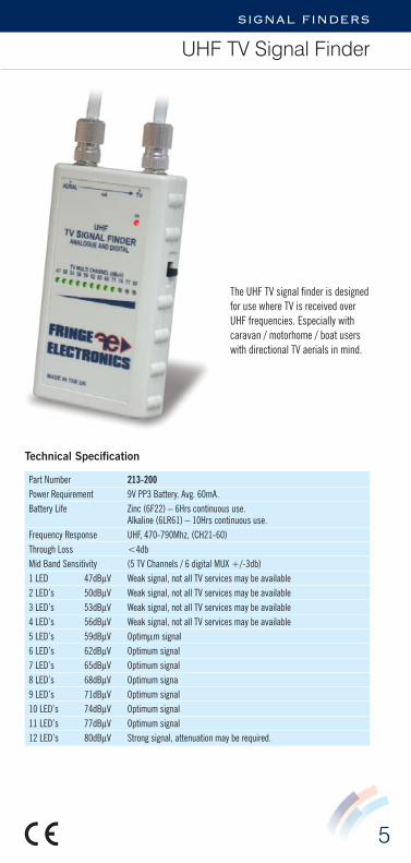
UHF TV Signal Finder
The UHF TV signal finder is designedfor use where TV is received overUHF frequencies. Especially withcaravan / motorhome / boat userswith directional TV aerials in mind.
Technical Specification
Part Number 213-200Power Requirement 9V PP3 Battery. Avg. 60mA. Battery Life Zinc (6F22) – 6Hrs continuous use.
Alkaline (6LR61) – 10Hrs continuous use. Frequency Response UHF, 470-790Mhz, (CH21-60) Through Loss <4dbMid Band Sensitivity (5 TV Channels / 6 digital MUX +/-3db)1 LED 47dBμV Weak signal, not all TV services may be available 2 LED’s 50dBμV Weak signal, not all TV services may be available 3 LED’s 53dBμV Weak signal, not all TV services may be available 4 LED’s 56dBμV Weak signal, not all TV services may be available 5 LED’s 59dBμV Optimμm signal 6 LED’s 62dBμV Optimum signal 7 LED’s 65dBμV Optimum signal8 LED’s 68dBμV Optimum signa9 LED’s 71dBμV Optimum signal 10 LED’s 74dBμV Optimum signal 11 LED’s 77dBμV Optimum signal 12 LED’s 80dBμV Strong signal, attenuation may be required.

6
SIGNAL FINDERS
Worldwide Signal Finder
The Worldwide VHF/UHF TV signalfinder is designed for use in anycountry that transmits TV over VHFor UHF frequencies. Especially withcaravan / motorhome / boat userswith VHF/UHF directional TV aerialsin mind.
Technical Specification
Part Number 213-210Power Requirement 9V PP3 Battery. Avg. 60mA. Battery Life Zinc (6F22) – 6Hrs continuous use.
Alkaline (6LR61) – 10Hrs continuous use. Frequency Response UHF, 470-790Mhz, (CH21-60); VHF, 47 -230MHzMid Band Sensitivity (5 TV Channels / 6 digital MUX +/-3db)1 LED 42dBμV Weak signal, not all TV services may be available 2 LED’s 45dBμV Weak signal, not all TV services may be available 3 LED’s 48dBμV Weak signal, not all TV services may be available 4 LED’s 51dBμV Weak signal, not all TV services may be available 5 LED’s 54dBμV Optimum signal 6 LED’s 57dBμV Optimum signal 7 LED’s 60dBμV Optimum signal 8 LED’s 63dBμV Optimum signa9 LED’s 66dBμV Optimum signal 10 LED’s 69dBμV Optimum signal 11 LED’s 72dBμV Optimum signal 12 LED’s 75dBμV Strong signal, attenuation may be required.
7
SIGNAL FINDERS
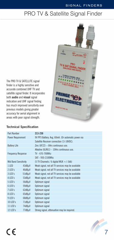
PRO TV & Satellite Signal Finder
The PRO TV & SATELLITE signalfinder is a highly sensitive andaccurate combined UHF TV andsatellite signal finder. It incorporatesboth audio and visual signalindication and UHF signal findinghas much improved sensitivity overprevious models giving greateraccuracy for aerial alignment inareas with poor signal strength.
Technical Specification
Part Number 213-230Power Requirement 9V PP3 Battery. Avg. 60mA. (Or automatic power via
Satellite Receiver connection 13-18VDC). Battery Life Zinc (6F22) – 6Hrs continuous use.
Alkaline (6LR61) – 10Hrs continuous use. Frequency Response TV - 470-790Mhz
SAT - 950-2100Mhz Mid Band Sensitivity (5 TV Channels / 6 digital MUX +/-3db)1 LED 43dBμV Weak signal, not all TV services may be available 2 LED’s 46dBμV Weak signal, not all TV services may be available 3 LED’s 51dBμV Weak signal, not all TV services may be available 4 LED’s 53dBμV Weak signal, not all TV services may be available 5 LED’s 56dBμV Optimum signal 6 LED’s 59dBμV Optimum signal 7 LED’s 62dBμV Optimum signal 8 LED’s 65dBμV Optimum signal 9 LED’s 68dBμV Optimum signal 10 LED’s 71dBμV Optimum signal 11 LED’s 74dBμV Optimum signal 12 LED’s 77dBμV Strong signal, attenuation may be required.
8
SIGNAL FINDERS
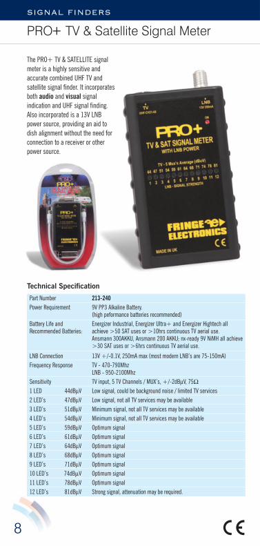
PRO+ TV & Satellite Signal Meter
The PRO+ TV & SATELLITE signalmeter is a highly sensitive andaccurate combined UHF TV andsatellite signal finder. It incorporatesboth audio and visual signalindication and UHF signal finding.Also incorporated is a 13V LNBpower source, providing an aid todish alignment without the need forconnection to a receiver or otherpower source.
Technical Specification
Part Number 213-240Power Requirement 9V PP3 Alkaline Battery.
(high peformance batteries recommended)Battery Life and Energizer Industrial, Energizer Ultra+ and Energizer Hightech all Recommended Batteries: achieve >50 SAT uses or >10hrs continuous TV aerial use.
Ansmann 300AKKU, Ansmann 200 AKKU; nx-ready 9V NiMH all achieve>30 SAT uses or >6hrs continuous TV aerial use.
LNB Connection 13V +/-0.1V, 250mA max (most modern LNB’s are 75-150mA)Frequency Response TV - 470-790Mhz
LNB - 950-2100Mhz Sensitivity TV input, 5 TV Channels / MUX’s, +/-2dBμV, 75Ω1 LED 44dBμV Low signal, could be background noise / limited TV services 2 LED’s 47dBμV Low signal, not all TV services may be available 3 LED’s 51dBμV Minimum signal, not all TV services may be available 4 LED’s 54dBμV Minimum signal, not all TV services may be available 5 LED’s 59dBμV Optimum signal 6 LED’s 61dBμV Optimum signal 7 LED’s 64dBμV Optimum signal 8 LED’s 68dBμV Optimum signal 9 LED’s 71dBμV Optimum signal 10 LED’s 74dBμV Optimum signal 11 LED’s 78dBμV Optimum signal 12 LED’s 81dBμV Strong signal, attenuation may be required.
9
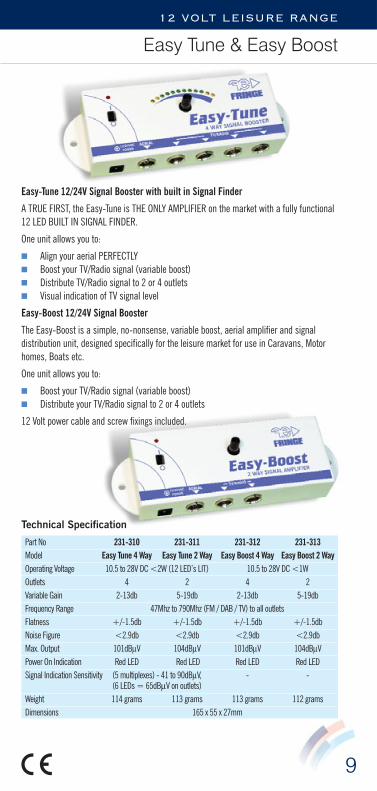
12 VOLT LEISURE RANGE
Easy Tune & Easy Boost
Technical Specification
Part No 231-310 231-311 231-312 231-313Model Easy Tune 4 Way Easy Tune 2 Way Easy Boost 4 Way Easy Boost 2 WayOperating Voltage 10.5 to 28V DC <2W (12 LED’s LIT) 10.5 to 28V DC <1WOutlets 4 2 4 2Variable Gain 2-13db 5-19db 2-13db 5-19dbFrequency Range 47Mhz to 790Mhz (FM / DAB / TV) to all outletsFlatness +/-1.5db +/-1.5db +/-1.5db +/-1.5dbNoise Figure <2.9db <2.9db <2.9db <2.9dbMax. Output 101dBμV 104dBμV 101dBμV 104dBμVPower On Indication Red LED Red LED Red LED Red LEDSignal Indication Sensitivity (5 multiplexes) - 41 to 90dBμV, - -
(6 LEDs = 65dBμV on outlets)Weight 114 grams 113 grams 113 grams 112 gramsDimensions 165 x 55 x 27mm
Easy-Tune 12/24V Signal Booster with built in Signal Finder
A TRUE FIRST, the Easy-Tune is THE ONLY AMPLIFIER on the market with a fully functional12 LED BUILT IN SIGNAL FINDER.
One unit allows you to:
■ Align your aerial PERFECTLY ■ Boost your TV/Radio signal (variable boost) ■ Distribute TV/Radio signal to 2 or 4 outlets■ Visual indication of TV signal level
Easy-Boost 12/24V Signal Booster
The Easy-Boost is a simple, no-nonsense, variable boost, aerial amplifier and signaldistribution unit, designed specifically for the leisure market for use in Caravans, Motorhomes, Boats etc.
One unit allows you to:
■ Boost your TV/Radio signal (variable boost) ■ Distribute your TV/Radio signal to 2 or 4 outlets
12 Volt power cable and screw fixings included.
10
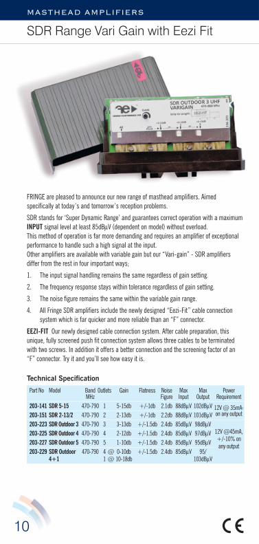
MASTHEAD AMPLIFIERS
SDR Range Vari Gain with Eezi Fit
FRINGE are pleased to announce our new range of masthead amplifiers. Aimedspecifically at today’s and tomorrow’s reception problems.
SDR stands for ‘Super Dynamic Range’ and guarantees correct operation with a maximumINPUT signal level at least 85dBμV (dependent on model) without overload.This method of operation is far more demanding and requires an amplifier of exceptionalperformance to handle such a high signal at the input. Other amplifiers are available with variable gain but our “Vari-gain” - SDR amplifiersdiffer from the rest in four important ways;
1. The input signal handling remains the same regardless of gain setting.
2. The frequency response stays within tolerance regardless of gain setting.
3. The noise figure remains the same within the variable gain range.
4. All Fringe SDR amplifiers include the newly designed “Eezi-Fit” cable connectionsystem which is far quicker and more reliable than an “F” connector.
EEZI-FIT Our newly designed cable connection system. After cable preparation, thisunique, fully screened push fit connection system allows three cables to be terminatedwith two screws. In addition it offers a better connection and the screening factor of an“F” connector. Try it and you’ll see how easy it is.
Technical Specification
Part No Model Band Outlets Gain Flatness Noise Max Max PowerMHz Figure Input Output Requirement
203-141 SDR 5-15 470-790 1 5-15db +/-1db 2.1db 88dBμV 102dBμV 12V @ 35mA,203-151 SDR 2-13/2 470-790 2 2-13db +/-1db 2.2db 88dBμV 101dBμV on any output
203-223 SDR Outdoor 3 470-790 3 3-13db +/-1.5db 2.4db 85dBμV 98dBμV203-225 SDR Outdoor 4 470-790 4 2-12db +/-1.5db 2.4db 85dBμV 97dBμV 12V @45mA,
203-227 SDR Outdoor 5 470-790 5 1-10db +/-1.5db 2.4db 85dBμV 95dBμV +/-10% on
203-229 SDR Outdoor 470-790 4 @ 0-10db +/-1.5db 2.4db 85dBμV 95/any output
4+1 1 @ 10-18db 103dBμV

11
MASTHEAD AMPLIFIERS
SDR Range Fixed Gain with Eezi Fit
Technical Specification
Part No Model Band Outlets Gain Flatness Noise Max Max PowerMHz Figure Input Output Requirement
203-161 SDR 13 470-790 1 13db +/-1dB 2.1db 94dBμV 107dBμV12V @ 35mA,203-121 SDR 16 470-790 1 16db +/-1dB 2.2db 88dBμV 104dBμV+/-10% on
203-171 SDR 9/2 470-790 2 9db +/-1dB 2.1db 94dBμV 103dBμV any output203-131 SDR 14/2 470-790 2 14db +/-1dB 2.2db 88dBμV 102dBμV203-222 SDR Outdoor 3 470-790 3 14db +/-1dB 2.4db 85dBμV 99dBμV
12V @ 45mA,203-224 SDR Outdoor 4 470-790 4 13db +/-1dB 2.4db 85dBμV 98dBμV+/-10% on
203-226 SDR Outdoor 5 470-790 5 11db +/-1dB 2.4db 85dBμV 96dBμV any output203-228 SDR Outdoor 470-790 4 @ 11db +/-1.5dB 2.4db 85dBμV 96/
4+1 1 @ 20db 103dBμV
FRINGE are pleased to announce our new range of masthead amplifiers. Aimedspecifically at today’s and tomorrow’s reception problems.
SDR stands for ‘Super Dynamic Range’ and guarantees correct operation with a maximumINPUT signal level at least 85dBμV (dependent on model) without overload.This method of operation is far moredemanding and requires an amplifier ofexceptional performance to handle such ahigh signal at the input.
EEZI-FIT Our newly designed cableconnection system. After cablepreparation, this unique, fully screenedpush fit connection system allows threecables to be terminated with two screws.In addition it offers a better connectionand the screening factor of an “F”connector. Try it and you’ll see how easy itis.
12
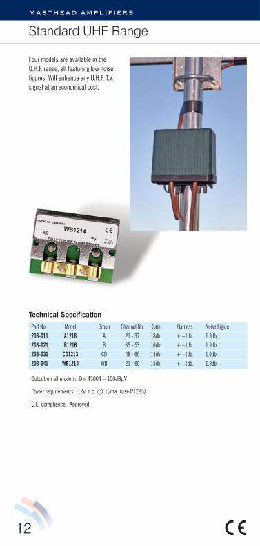
masthead amplifiers
Standard UHF Range
Technical Specification
Part No Model Group Channel No. Gain Flatness Noise Figure203-011 A1218 A 21 - 37 18db. + –1db. 1.9db.203-021 B1216 B 35 - 53 16db. + –1db. 1.9db.203-031 CD1213 CD 48 - 60 14db. + –1db. 1.9db.203-041 WB1214 WB 21 - 60 15db. + –1db. 1.9db.
Output on all models: Din 45004 – 100dBμV
Power requirements: 12v. d.c. @ 15ma (use P1285)
C.E. compliance: Approved
Four models are available in theU.H.F. range, all featuring low noisefigures. Will enhance any U.H.F. T.V.signal at an economical cost.

13
MASTHEAD AMPLIFIERS
Standard VHF Range
Two models are available in the V.H.F range, all feature low noise figures. The V.H.F. 1220-F.M. is suitable for the improvement of V.H.F./F.M. radio reception in Europe and the U.K.
The V.H.F. 1220-3 is ideal for amplifying DAB signals in remote reception areas.
Technical Specification
Part No Model Group Gain Flatness Noise Figure204-021 VHF1220-FM Band 2 20db. + –1db. 1.8db.204-031 VHF1220-3 Band 3/DAB 20db. + –1db. 1.8db.
Output on all models: Din 45004 – 100dBμV
Power requirements: 12v. d.c. @ 10ma (use P1285)
C.E. compliance: Approved

14
MASTHEAD AMPLIFIERS
Super UHF Range
Technical Specification
Part No Model Group Channel No. Gain Flatness Noise Figure202-011 A1228 A 21 - 37 28db. + –1.5db. 2.8db.202-021 B1226 B 35 - 53 26db. + –1.5db. 2.8db.202-031 CD1223 CD 48 - 60 23db. + –1.5db. 2.8db.202-041 WB1222 WB 21 - 60 22db. + –1.5db. 2.8db.
Output on all models: Din 45004 – 98dBμV
Power requirements: 12v. d.c. @ 32ma (use P1285)
C.E. compliance: Approved
Four models are available in thisrange, all feature high gain and lownoise figures.
Ample gain is available to overcomelosses incurred in long cable runs,and passive splitting.

15
MASTHEAD AMPLIFIERS
Supreme UHF Range
Technical Specification
Part No Model Group Channel No. Gain Flatness Noise Figure201-011 A1230 A 21 - 37 30db. + –1.5db. 1.9db.201-021 B1228 B 35 - 53 28db. + –1.5db. 1.9db.201-031 CD1225 CD 48 - 60 25db. + –1.5db. 1.9db.201-041 WB1225 WB 21 - 60 25db. + –1.5db. 1.9db.
Output on all models: Din 45004 – 106dBμV
Power requirements: 12v. d.c. @ 32ma (use P1285)
C.E. compliance: Approved
Four models are available in this range, all feature very low noise figures, high gain andhigh output capability. From 35dBμV of aerial signal much improved digital quality may beobtained.
Ideal head unit for Cascade systems.

16
MASTHEAD AMPLIFIERS
WB 22/2 & Cascade
Technical Specification
Part No 205-031 206-011Model WB 22/2 CascadeFrequency Range 470-790MHz 470-790MHzGain per leg 18db +/-1.5db 23db +/-1.5dbNoise Figure 2.9db 3.5dbOutput 2 x 96dBμV per leg 102dBμVUHF Input CH21-60 470-790MHz CH21-60 470-790MHzPower Requirements 12v dc @ 14ma (use P1285) 12v dc @ 32ma (use P1285)CE Compliance Approved Approved
The WB22/2 is a wide band U.H.F. amplifier with in-built low loss splitter. This enables twotelevision sets to operate from one masthead amplifier. The power unit must be switchedon to operate either T.V. In strong signal reception areas each leg may be split again usingFringe Inductive Splitters; this enables 2, 3 or 4 set reception.
The Cascade U.H.F. repeater amplifier is a through powered unit, designed to operate inconjunction with any Fringe masthead amplifier. This enables long coaxial cable runs to beused where the T.V. is remote from the aerial. Depending on the model of masthead,channel group, and aerial signal available a distance of 200 metres may be obtained,using standard grade coaxial cable, one masthead, and one Cascade amplifier. A distanceof 800 metres may be obtained, by using distribution grade coaxial cable, and threeCascade amplifiers.
17
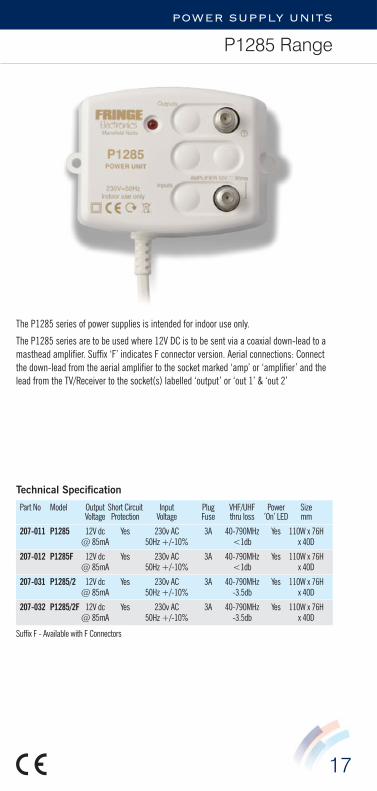
POWER SUPPLY UNITS
P1285 Range
The P1285 series of power supplies is intended for indoor use only.
The P1285 series are to be used where 12V DC is to be sent via a coaxial down-lead to amasthead amplifier. Suffix ‘F’ indicates F connector version. Aerial connections: Connectthe down-lead from the aerial amplifier to the socket marked ‘amp’ or ‘amplifier’ and thelead from the TV/Receiver to the socket(s) labelled ‘output’ or ‘out 1’ & ‘out 2’
Technical Specification
Part No Model Output Short Circuit Input Plug VHF/UHF Power SizeVoltage Protection Voltage Fuse thru loss ’On’ LED mm
207-011 P1285 12V dc Yes 230v AC 3A 40-790MHz Yes 110W x 76H@ 85mA 50Hz +/-10% <1db x 40D
207-012 P1285F 12V dc Yes 230v AC 3A 40-790MHz Yes 110W x 76H@ 85mA 50Hz +/-10% <1db x 40D
207-031 P1285/2 12V dc Yes 230v AC 3A 40-790MHz Yes 110W x 76H@ 85mA 50Hz +/-10% -3.5db x 40D
207-032 P1285/2F 12V dc Yes 230v AC 3A 40-790MHz Yes 110W x 76H@ 85mA 50Hz +/-10% -3.5db x 40D
Suffix F - Available with F Connectors
18
SET BACK RANGE
Single and Multiple Outlets
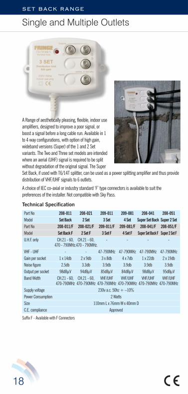
A Range of aesthetically pleasing, flexible, indoor useamplifiers, designed to improve a poor signal, orboost a signal before a long cable run. Available in 1to 4 way configurations, with option of high gain,wideband versions (Super) of the 1 and 2 Setvariants. The Two and Three set models are intendedwhere an aerial (UHF) signal is required to be splitwithout degradation of the original signal. The SuperSet Back, if used with T6/14T splitter, can be used as a power splitting amplifier and thus providedistribution of VHF/UHF signals to 6 outlets.
A choice of IEC co-axial or industry standard ‘F’ type connectors is available to suit thepreferences of the installer. Not compatible with Sky Pass.
Technical Specification
Part No 208-011 208-021 209-011 209-081 208-041 208-051Model Set Back 2 Set 3 Set 4 Set Super Set Back Super 2 SetPart No 208-011/F 208-021/F 209-011/F 209-081/F 208-041/F 208-051/FModel Set Back F 2 Set F 3 Set F 4 Set F Super Set Back F Super 2 Set FU.H.F. only CH.21 - 60, CH.21 - 60, - - - -
470 - 790MHz.470 - 790MHz.VHF - UHF - - 47-790MHz 47-790MHz 47-790MHz 47-790MHzGain per socket 1 x 14db 2 x 9db 3 x 8db 4 x 7db 1 x 22db 2 x 19dbNoise figure 2.5db 3.3db 3.9db 3.9db 3.9db 3.9dbOutput per socket 98dBμV 94dBμV 85dBμV 84dBμV 98dBμV 95dBμVBand Width CH.21 - 60, CH.21 - 60, VHF/UHF VHF/UHF VHF/UHF VHF/UHF
470-790MHz 470-790MHz 470-790MHz 470-790MHz 470-790MHz 470-790MHzSupply voltage 230v a.c. 50hz + –10% Power Consumption 2 WattsSize 110mm L x 76mm W x 40mm DC.E. compliance Approved
Suffix F - Available with F Connectors
19
DISTRIBUTION AMPLIFIERS
Mini 4 Range
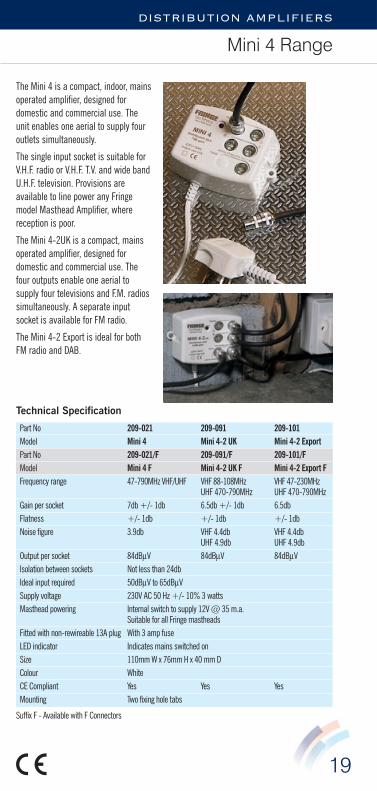
The Mini 4 is a compact, indoor, mainsoperated amplifier, designed fordomestic and commercial use. Theunit enables one aerial to supply fouroutlets simultaneously.
The single input socket is suitable forV.H.F. radio or V.H.F. T.V. and wide bandU.H.F. television. Provisions areavailable to line power any Fringemodel Masthead Amplifier, wherereception is poor.
The Mini 4-2UK is a compact, mainsoperated amplifier, designed fordomestic and commercial use. Thefour outputs enable one aerial tosupply four televisions and F.M. radiossimultaneously. A separate inputsocket is available for FM radio.
The Mini 4-2 Export is ideal for bothFM radio and DAB.
Technical Specification
Part No 209-021 209-091 209-101Model Mini 4 Mini 4-2 UK Mini 4-2 ExportPart No 209-021/F 209-091/F 209-101/FModel Mini 4 F Mini 4-2 UK F Mini 4-2 Export FFrequency range 47-790MHz VHF/UHF VHF 88-108MHz VHF 47-230MHz
UHF 470-790MHz UHF 470-790MHzGain per socket 7db +/- 1db 6.5db +/- 1db 6.5dbFlatness +/- 1db +/- 1db +/- 1dbNoise figure 3.9db VHF 4.4db VHF 4.4db
UHF 4.9db UHF 4.9dbOutput per socket 84dBμV 84dBμV 84dBμVIsolation between sockets Not less than 24dbIdeal input required 50dBμV to 65dBμVSupply voltage 230V AC 50 Hz +/- 10% 3 wattsMasthead powering Internal switch to supply 12V @ 35 m.a.
Suitable for all Fringe mastheadsFitted with non-rewireable 13A plug With 3 amp fuseLED indicator Indicates mains switched onSize 110mm W x 76mm H x 40 mm DColour WhiteCE Compliant Yes Yes YesMounting Two fixing hole tabs
Suffix F - Available with F Connectors

20
DISTRIBUTION AMPLIFIERS
LDU Range with F Connectors
Designed for domestic and commercial use, these amplifiers have two inputs for both VHFradio (FM/DAB) and UHF TV. ‘Sky’ set top box RF2 signals can be distributed via the UHFsocket and if additional remote control ‘eyes’ are fitted between the outlets and TV, theamplifier will pass the remote control signals back to the satellite receiver. Theseamplifiers must be fitted indoors and are designed for continuous operation. The remotereturn path function has a ‘test’ LED that blinks in unison with the return path signal. Thisconfirms passing of the remote control signal and hence a good cable connection betweenthe LDU and the remote eye.
Technical Specification
Part No 215-011/F 215-021/F 215-031/FModel 4 Way LDU 6 Way LDU 8 Way LDUVHF Frequency Range 88 - 235MHz 88 - 235MHz 88 - 235MHzUHF Frequency Range 47 - 790MHz 47 - 790MHz 47 - 790MHz
CH21-60 CH21-60 CH21-60Return Path Freq. Range/Gain 5-30MHz / 0-3db 5-30MHz / 0-3db 5-30MHz / 0-3dbGain per socket 8db 8db 8dbFlatness VHF, +/-0.5db VHF, +/-0.5db VHF, +/-0.5db
UHF, +/-1db UHF, +/-1db UHF, +/-1dbNoise figure VHF, <4.5db VHF, <4.5db VHF, <4.5db
UHF, <3.5db UHF, <3.5db UHF, <3.7dbOutput per socket 95 dBμV 95 dBμV 95 dBμVIsolation Typically 38db Typically 38db Typically 38dbMaximum Input 87dBμV 87dBμV 87dBμVMains Supply 230V AC 50 Hz +/- 10% 3 wattsFitted with non-rewireable 13A plug With 3 amp fuseLED indicators MAINS ON and TEST LED - see aboveReturn Path Frequency Gain 5-30MHz/0-3dbRemote Eye Power 9V @ 10mA at each outputSize ‘F’ socket version 207mm W x 96mm H x 61mm DWeight 700gCompliance CE approved, ROHS compliant

21
DISTRIBUTION AMPLIFIERS
6 Way, 7 Way, 8 Way, HOP & SHOP
Technical Specification
Part No 209-031 209-061 209-071 209-041 209-051Model 6 Way 7 Way 8 Way High Output Split H. OutputPart No 209-031/F 209-061/F 209-071/F 209-041/F 209-051/FModel 6 Way F 7 Way F 8 Way F High Output F Split H. Output FVHF Frequency Range, MHz 47 - 230 47 - 230 47 - 230UHF Frequency Range, MHz 470 - 790 470 - 790 470 - 790
47 - 790 47 - 790
Channels 21-60 / 1-13 21-60 / 1-13 21-60 / 1-13 1-60 1-60Gain per socket 6@7db [email protected] [email protected] 1@28db 2@24dbFlatness VHF +/-1.5db +/-1.0db +/-1.0db - -
UHF +/-1.5db +/-1.5db +/-1.5db +/-1.5db +/-1.5dbNoise figure VHF 3.4db 3.4db 3.4db - -
UHF 3.8db <3.8db <3.8db 3.4db VHF/UHF 3.4db VHF/UHFMax. Output 85 dBμV 85 dBμV 85 dBμV 107dBμV 103dBμV(DIN 45005) SpursSide Rejection Worst Case 33db 30db 33db N/A N/A(Isolation) Typical 38db 36db 38dbIdeal Input required 50dBμV min and should not exceed 79dBμVUHF Masthead External switch to supply 12v DC @ 35ma.
Suitable for all Fringe mastheads. Shipped in the OFF positionMains Supply 230V AC 50 Hz +/- 10% 3 wattsFitted with non-rewireable 13A plug With 3 amp fuseTwo LED indicators Indicates MAINS ON and LINE POWER onFixing Two tabs, fixing centres 193mmSize 207mm W x 96mm H x 51mm DWeight 700gCE Compliance Approved
These TV/FM and DAB Radio Distribution Amplifiers enables one aerial to supply up to 8TV’s/radios simultaneously. Freeview/DVD/Video may be distributed by these amplifiers,via the UHF input socket. Inaddition, a full output socketon the 7 Way version isprovided so that up to 19points may be served byadding two Fringe T6splitter units (availableseparately).
The HOP/SHOP(High Output/SplitHigh Output)amplifiers have asingle/doubleoutput that may be split to up to 18 outlets for the HOP and 24 outlets for the SHOP, usingFringe T6 splitter units (available separately).
On all models, provision is also available to line power any masthead amplifier connectedto the UHF input. For indoor use only. These amplifiers are not suitable for Sky remotepass.

Technical Specification
Part No Model Tap down Isolation Through Loss210-011 T6/21 -21db. 40db. 3.5db.210-021 T6/17 -17db. 34db. 3.5db.210-031 T6/14ST -14db. 25db. Terminal
Figures quoted assume all outputs are terminated 75ohm
Frequency range - 0 - 860MHzFixing - Two screw holesColour - White 1 Gang mounting frameFixing area - 88mm L x 88mm W.C.E. compliance - Approved
22
DISTRIBUTION AMPLIFIERS
T6 Splitter Range
A range of resistive splitter units, for use with Fringe 7 Way – High Output – Split HighOutput and Super Setback.
Three models of attenuation are available, fitted with sockets. Supplied with applicationnotes.

23
PASSIVE ACCESSORIES
Splitters
Technical Specification
Part No 211-021 211-411 211-412 211-321Model 2 Way Inductive 3 Way Eezi-Fit 4 Way Eezi-Fit 2 Way ScreenedFrequency Range VHF-UHF 40Mhz to 790Mhz widebandAverage Insertion Loss -3.5db - - -3.5dbThrough Loss - 1 -7.5db -7.5db -
2 -7.5db3 -4db
Side Rejection 20db 1 to 2 -18db 1 to 2 & 3 to 4 -18db 20db3 or 4 to 1 or 2 -23db
DC Pass Common to 1 Common to any Common to any Common to 1
2 Way External Inductive Combiner/Splitter
This unit is an ultra-wideband low loss outdoorunit for combining and splitting VHF & UHFsignals. It has a low insertion loss and goodisolation between inputs.
3/4 Way External Inductive Splitter
The Fringe 3 and 4 Way external inductivesplitters are ultra-wideband, low loss units forsplitting VHF and UHF signals to up to 4TV’s/Radios. In strong signal areas theyprovide easy signal distribution, without theneed for additional masthead amplification.With Eezi-Fit connections.
24
PASSIVE ACCESSORIES
Filters and Joint Box
Technical Specification
Part No Model Pass Channels Rejection of other channels Through Loss
212-011 Group A 21 - 34 >15db Not exceeding 2db212-021 Group B 39 - 53 >15db Not exceeding 2db212-031 Group CD 48 - 60 >15db Not exceeding 2db212-032 Group 21-37 52 - 60 >15db Not exceeding 2db212-081 Joint Box 0 - 790MHz N/A 0.25db
Part No Model Pass Band Rejection Average through loss212-091 Tetra UHF High Pass UHF TV Tetra 380-400MHz -1db
470 - 790MHz typical 35db guaranteed 30db
212-095 4 G Filter 5 - 782MHz CH60 <-5db-9.5db @ 786MHz
LTE Downlink791-821MHz -15dB to -32db
LTE Uplink832-862MHz -38dB to -51db
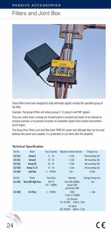
These filters have been designed to help eliminate signals outside the specified group ofthe filter.
Example: The group B filter will reduce group C- D, group A and VHF signals.
They are useful when a strong out of band signal is present and needs to be reduced toprevent overload, or to prevent reception of unwanted signals from distant transmittersout of region.
The Group Pass Filters and Joint Box have THRU DC power and although they can be usedbetween the aerial and amplifier it is preferable to use them after the amplifier.

25
PASSIVE ACCESSORIES
Diplexers UHF – UHF
Part No. Description From Ch to Ch211-031 A to E 21-34 to 39-60211-061 A to E thru A 21-34 to 39-60211-071 A to E thru E 21-34 to 39-60211-041 K to CD 21-47 to 48-60211-081 K to CD thru K 21-47 to 48-60211-091 K to CD thru CD 21-47 to 48-60211-121 Special K to CD 50/52 21-50 to 52-60211-131 Special K to CD 50/52 thru K 21-50 to 52-60211-141 Special K to CD 50/52 thru CD 21-50 to 52-60211-142 Special K to CD 50/52 thru both 21-50 to 52-60211-181 A+37 to E 21-37 to 40-60211-191 A+37 to E thru A 21-37 to 40-60211-201 A+37 to E thru E 21-37 to 40-60
Diplexers, Eezi-Fit UHF-UHF screened and switchable DC pass. CE compliant.
211-124 A to E switchable both 21-34 to 39-60211-126 A+37 to E switchable both 21-37 to 40-60211-128 Special K to CD 46/48 switchable both 21-46 to 48-60211-125 Special K to CD 50/52 switchable both 21-50 to 52-60211-127 Special K to CD 51/53 switchable both 21-51 to 53-60
Other combinations available. Please call us with your requirements.
The diplexers above are supplied as electromagnetically benign apparatus. They shouldnot be used where installation will compromise the integrity of a system. i.e. MATV etc. CEmarked product should be used if in doubt.
UHF- UHF diplexers are no longer a stock item andare only made to order. Orders for a specificdiplexer must be in multiplies of 20 units andallow a lead time of 4 weeks from placement oforder to dispatch.

26
ADDENDUM
UHF Channel Allocation
Programme providers BBC ITV 1,2 HD ITV 3 Sky News BT Sport1,2,3,4 Ch 4,5 Channels Drama Dave 4 Music
Quest Travel YesterdayPS
B 1
PSB
2
PSB
3
COM
4
COM
5
COM
6
Aeria
lGr
oup
Polar
isatio
n
STATION CHANNEL NUMBER
Borders
CALDBECK 25 28 30 23 26 29 A H
Haltwhistle 59 50 55 CD V
Kendal 60 53 57 CD V
Whitehaven 43 40 46 B V
CALDBECK SCOTLAND 27 24 22 A H
Cambret Hill 44 41 47 B H
SELKIRK 50 59 55 57 53 60 C/D H
Central Scotland
BLACK HILL 46 43 40 41 44 47 B H
Torosay 28 25 22 23 26 29 A V
Glengorm 44 41 47 B V
DARVEL 22 25 28 23 26 29 A H
Millburn Muir 42 45 39 B V
Rosneath 49 58 54 53 57 60 CD H/V
CRAIGKELLY 27 24 21 42 45 39 WB H
ANGUS 60 53 57 54 58 49 CD H
Perth 39 42 45 B V
Tay Bridge 41 47 44 B V
East Anglia
TACOLNESTON 55 59 50 42 45 39 E/WB H
Lowestoft 58 60 56 CD V
Norwich Central 46 43 52 B V
Kings Lynn 40 46 43 B V
Wells next the Sea 57 51 56 CD V
West Runton 26 23 29 A V
Aldeburgh 28 23 25 A V
SUDBURY 44 41 47 58 60 56 WB H
SANDY HEATH 27 24 21 51 52 48 WB H
Type in capitals indicates a main transmitter. Generally transmitters of less than 200 watts ERP are notincluded.Further information may be obtained from the following web sites www.ukfree.tv www.ofcom.org.uk

27
ADDENDUM
UHF Channel Allocation
Programme providers BBC ITV 1,2 HD ITV 3 Sky News BT Sport1,2,3,4 Ch 4,5 Channels Drama Dave 4 Music
Quest Travel Yesterday
PSB
1
PSB
2
PSB
3
COM
4
COM
5
COM
6
Aeria
lGr
oup
Polar
isatio
n
STATION CHANNEL NUMBER
Grampian & Highlands
DURRIS 28 25 22 23 26 29 A H
Bressay 28 25 22 27 24 21 A V
Collafirth Hill 45 42 39 B V
Gartley Moor 58 49 54 CD V
Peterhead 50 59 55 CD V
Rosehearty 44 41 47 B V
EITSHAL 26 23 29 25 22 28 A H
KEELYLANG HILL 46 43 40 42 45 39 B H
KNOCKMORE 26 23 29 53 57 60 WB H
ROSEMARKIE 45 39 42 43 46 40 B H
RUMSTER FOREST 27 24 21 30 59 55 WB H
Skriaig 27 24 21 A V
London and South East of England
CRYSTAL PALACE 23 26 30 25 22 28 A H
Guildford 43 46 40 48 52 49 B V
Hemel Hempstead 44 41 47 50 59 55 WB V
Reigate 60 57 53 21 24 27 WB V
BLUEBELL HILL 46 43 40 45 39 54 WB H
DOVER 50 51 53 55 59 48 CD H
Midlands
OXFORD 53 60 57 50 59 55 CD H
RIDGE HILL 28 25 22 21 24 27 A H
SUTTON COALFIELD 43 46 40 42 45 39 B H
Brierley Hill 60 57 53 50 59 55 CD V
Bromsgrove 26 23 30 41 44 47 WB V
Fenton 24 27 21 25 22 28 A V
Lark Stoke 26 23 30 41 44 47 WB V
Malvern 53 57 60 50 59 55 CD V
THE WREKIN 26 23 30 41 44 47 WB H
WALTHAM 49 54 58 29 56 57 WB H
Nottingham 27 24 21 51 52 48 WB V
Stanton Moor 59 50 55 CD V
28
ADDENDUM
UHF Channel Allocation
Programme providers BBC ITV 1,2 HD ITV 3 Sky News BT Sport1,2,3,4 Ch 4,5 Channels Drama Dave 4 Music
Quest Travel YesterdayPS
B 1
PSB
2
PSB
3
COM
4
COM
5
COM
6
Aeria
lGr
oup
Polar
isatio
n
STATION CHANNEL NUMBER
North East
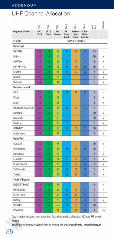
BILSDALE 26 29 23 43 46 40 WB H
Whitby 55 59 50 CD V
CHATTON 45 42 39 41 44 47 B H
PONTOP PIKE 58 54 49 50 59 55 CD H
Fenham 27 24 21 25 22 28 A V
Newton 26 29 23 A V
Weardale 44 47 41 B V
Northern Ireland
DIVIS 27 21 24 23 26 29 A H
Kilkeel 45 42 39 B V
Larne 45 42 39 B V
BROUGHER MOUNTAIN 28 22 25 21 24 27 A H
Camlough 59 55 50 CD V
Newcastle 50 55 59 CD V
Strabane 45 42 39 B V
LIMAVADY 50 59 55 54 58 49 CD H
Londonderry 44 41 47 B V
North West
DOUGLAS 53 60 57 CD V
WINTER HILL 50 59 54 58 49 55 CD H
Haslingden 26 23 29 A V
Lancaster 27 24 21 25 28 22 A V
Pendale Forest 28 25 22 27 21 24 A V
Saddleworth 45 39 42 51 52 48 B V
Storeton 28 25 22 23 26 29 A V
South of England
FREMONT POINT 44 41 47 B H
HANNINTON 45 42 39 41 44 47 B H
HEATHFIELD 52 49 47 42 44 41 B H
Hastings 25 28 22 23 26 30 A V
MIDHURST 55 56 58 54 59 50 CD H
ROWRIDGE 24 27 21 25 22 28 A H/V
Type in capitals indicates a main transmitter. Generally transmitters of less than 200 watts ERP are notincluded.Further information may be obtained from the following web sites www.ukfree.tv www.ofcom.org.uk

29
ADDENDUM
UHF Channel Allocation
Programme providers BBC ITV 1,2 HD ITV 3 Sky News BT Sport1,2,3,4 Ch 4,5 Channels Drama Dave 4 Music
Quest Travel Yesterday
PSB
1
PSB
2
PSB
3
COM
4
COM
5
COM
6
Aeria
lGr
oup
Polar
isatio
n
STATION CHANNEL NUMBER
South of England continued
Findon 44 41 47 B V
Salisbury 57 60 53 50 59 55 CD V
Tunbridge Wells 52 49 47 42 44 41 B V
Whitehawk Hill Brighton 60 53 51 57 56 48 CD V
Wales
BLAENPLWYF 27 24 21 25 22 28 A H
CARMEL 60 53 57 54 58 49 CD H
Llandrindod Wells 39 42 45 B V
Kilvey Hill 23 26 29 25 22 28 A V
LLANDDONA 57 60 53 43 46 40 WB H
Arfon 41 44 47 B V
Conway 47 41 44 B V
Long Mountain 60 53 57 CD V
MOEL Y PARC 45 39 42 51 52 48 B H
Storeton 57 53 60 CD H
PRESELI 43 46 40 42 45 39 B H
WENVOE 41 44 47 42 45 39 B H
Abergavenny 39 42 45 B V
Mynydd Machen 23 26 29 A V
Pontypridd 25 22 28 A V
Rhondda 23 26 29 A H/V
West Country
MENDIP 49 54 58 48 56 52 CD H
Bristol I.C. 41 44 47 42 45 39 B V
Bristol K.W. 43 40 46 53 57 60 WB V
BEACON HILL 60 53 57 42 45 51 WB H
CARADON HILL 28 25 22 21 24 27 A H
Plympton 54 49 58 42 45 56 WB V
HUNTSHAW CROSS 50 59 55 48 52 56 DC H
REDRUTH 44 41 47 48 52 51 B H
STOCKLAND HILL 26 23 29 25 22 28 A H
Budleigh Salterton 60 53 57 CD V
Weymouth 47 44 41 B V

30
ADDENDUM
UHF Channel Allocation
Programme providers BBC ITV 1,2 HD ITV 3 Sky News BT Sport1,2,3,4 Ch 4,5 Channels Drama Dave 4 Music
Quest Travel YesterdayPS
B 1
PSB
2
PSB
3
COM
4
COM
5
COM
6
Aeria
lGr
oup
Polar
isatio
n
STATION CHANNEL NUMBER
Yorkshire
BELMONT 22 25 28 30 53 60 WB H
Chesterfield 26 23 29 43 46 40 WB V
EMLEY MOOR 47 44 41 51 52 48 B H
Keighley 49 58 54 57 53 60 CD V
Skipton 39 45 42 B V
Warfedale 25 22 28 A V
OLIVERS MOUNT 57 60 53 54 58 49 CD V
SHEFFIELD 27 25 21 42 45 39 WB V
Type in capitals indicates a main transmitter. Generally transmitters of less than 200 watts ERP are notincluded.Further information may be obtained from the following web sites www.ukfree.tv www.ofcom.org.uk
RTE Saorview Digital TV Channels
CHANNEL NUMBER
Station Area Mux 1 Mux 2 Aerial Group Polarisation
Cairn Hill Co. Longford 47 44 B H
Clermont Cairn Co. Louth 52 56 CD V
Dungarvan Co. Waterford 55 59 CD H
Hollywell Hill Co. Donegal 30 33 A H
Kippure Co. Wicklow 54 58 CD H
Maghera Co. Clare 48 55 CD H
Mount Leinster Co. Wexford 23 26 A H
Mullaghanish Co. Kerry 21 24 A H
Spur Hill Co. Cork 45 49 B H
Three Rock Dublin 30 33 A H
Truskmore Co. Sligo 53 57 CD H
Woodcock Hill Co. Clare 47 44 B H
Only main transmitters are shownFor more information: www.saorview.ie www.2rn.ie
ADDENDUM
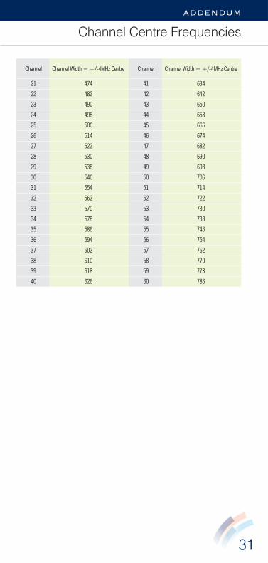
Channel Centre Frequencies
Channel Channel Width = +/-4MHz Centre
21 474
22 482
23 490
24 498
25 506
26 514
27 522
28 530
29 538
30 546
31 554
32 562
33 570
34 578
35 586
36 594
37 602
38 610
39 618
40 626
Channel Channel Width = +/-4MHz Centre
41 634
42 642
43 650
44 658
45 666
46 674
47 682
48 690
49 698
50 706
51 714
52 722
53 730
54 738
55 746
56 754
57 762
58 770
59 778
60 786
31
32
ADDENDUM
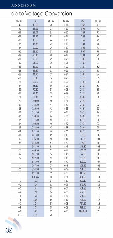
db. mv. uv. db. uv. db. mv. mv. db. uv.-40 10.00 20 +11 3.55 71-39 11.22 21 +12 3.98 72-38 12.59 22 +13 4.47 73-37 14.13 23 +14 5.01 74-36 15.85 24 +15 5.62 75-35 17.78 25 +16 6.31 76-34 20.00 26 +17 7.08 77-33 22.40 27 +18 7.94 78-32 25.10 28 +19 8.91 79-31 28.20 29 +20 10.00 80-30 31.60 30 +21 11.22 81-29 35.50 31 +22 12.59 82-28 39.80 32 +23 14.13 83-27 44.70 33 +24 15.85 84-26 50.10 34 +25 17.78 85-25 56.20 35 +26 19.95 86-24 63.10 36 +27 22.39 87-23 70.80 37 +28 25.12 88-22 79.40 38 +29 28.18 89-21 89.10 39 +30 31.62 90-20 100.00 40 +31 35.48 91-19 112.20 41 +32 39.81 92-18 125.90 42 +33 44.67 93-17 141.30 43 +34 50.12 94-16 158.50 44 +35 56.23 95-15 177.80 45 +36 63.10 96-14 199.50 46 +37 70.79 97-13 223.90 47 +38 79.43 98-12 251.20 48 +39 89.13 99-11 281.80 49 +40 100.00 100-10 316.20 50 +41 112.20 101-9 354.80 51 +42 125.90 102-8 398.10 52 +43 141.30 103-7 446.70 53 +44 158.50 104-6 501.20 54 +45 177.80 105-5 562.30 55 +46 199.50 106-4 631.00 56 +47 223.90 107-3 707.90 57 +48 251.20 108-2 794.30 58 +49 281.80 109-1 891.30 59 +50 316.20 1100 1.00mv 60 +51 354.80 111
+1 1.12 61 +52 398.10 112+2 1.26 62 +53 446.70 113+3 1.41 63 +54 501.20 114+4 1.58 64 +55 562.30 115+5 1.78 65 +56 631.00 116+6 2.00 66 +57 707.90 117+7 2.24 67 +58 794.30 118+8 2.51 68 +59 891.30 119+9 2.82 69 +60 1000.00 120
+10 3.16 70
db to Voltage Conversion

33
ADDENDUM
Details of Specifications
All products listed are 75ohms and measurements are taken at that impedance.
OUTPUT LEVELS
These are to the DIN 45004/B 3 tone test at –60 IMD.
NOISE FIGURES
These are the average of five measurements taken across the full specified bandwidth ofthe amplifier. The noise figure variation across the bandwidth does not exceed +–1db.Measurements are made using a direct reading meter with a modulated solid state noisesource.
LIMITS OF ACCURACY
Measurements are taken from random production samples and may deviate by theaccuracy of the instruments used. Variations in production can occur but a worst caseshould not degrade specification by more than 1db. A list of current instruments isavailable on request.
All products are 100% tested for gain/loss and masthead amplifiers are also given asubjective performance test on a T.V.
CE STANDARDS
Parts of EN50082-1Parts of EN50081-1EN55014Where applicable EN60056
Fringe Electronics Ltd. reserve the right to improve and change specifications without notice.

34
addendum
Eezi-Fit from Fringe
The unique new push fit connection fromFringe.
It’s as easy as 1231 Prepare the cable.
There is a handy strip guide onthe can label.
2 Thread the prepared cable throughthe case grommet, under thecable clamp and push into theEezi-Fit fitting.
3 Fully tighten the clamp screws.
If subsequent cable removal isrequired, simply bush the whitebutton and pull the cable out ofthe fitting.
Try FringeWe won’t let you down
More SDR amplifiers with Eezi-Fit are on the way from Fringe
Manufactured in the UK

35
addendum
Notes

FRINGE ELECTRONICS LIMITEDELECTRONIC EQUIPMENT MANUFACTURERSFringe House, 4 Highfield Road, Clipstone, Mansfield, Notts. NG21 9ER Tel: 01623 643802 [email protected] [email protected]
www.fringeelectronics.co.uk
MADE IN THE UK
D E A L E R S S T A M P
U . H . F. R E C E I V I N G A E R I A L
G R O U P S A N D C O L O U R C O D E S
CHANNELS GROUP COLOUR21-37 A RED35-53 B YELLOW48-60 CD GREEN35-60 E BROWN21-60 W WHITE21-47 K –
G U A R A N T E E T E R M S
All fringe products are unconditionally guaranteed for a period of three years fromdate of purchase. This is on a ‘return to base’ basis. Please contact us if you wouldlike to claim repair or replacement under these terms. Statutory rights are notaffected. All Fringe manufactured product contain coded date of manufactureinformation.
C O P Y R I G H T
Products listed in this catalogue are subject to copyright. This includes mechanicaland electrical components, packaging and instruction sheets.
The name Fringe and the logo is a registered trademark and is dulyprotected.
Reproduction in part or whole of the catalogue without prior consent is prohibited.
L I A B I L I T Y
Every effort has been made to ensure that the information given in this catalogue iscorrect. The company accepts no liability in respect of loss arising from errors in theinformation provided.
ISSUE DATE: JANUARY 2014