temperature control units · temperature control units ... omron. no patent liability ......
TRANSCRIPT

Machine Automation Controller
CJ-series
Temperature Control Units
Temperature Control Units
Operation Manualfor NJ-series CPU Unit
W491-E1-01
CJ1W-TC003CJ1W-TC004CJ1W-TC103CJ1W-TC104

All rights reserved. No part of this publication may be reproduced, stored in a retrieval system, or transmitted, in any form, or by any means, mechanical, electronic, photocopying, recording, or otherwise, without the prior written permission of OMRON.
No patent liability is assumed with respect to the use of the information contained herein. Moreover, because OMRON is constantly striving to improve its high-quality products, the information contained in this manual is subject to change without notice. Every precaution has been taken in the preparation of this manual. Nevertheless, OMRON assumes no responsibility for errors or omissions. Neither is any liability assumed for damages resulting from the use of the information contained in this publication.
OMRON, 2011

1
Introduction
CJ-series Temperature Control Units Operation Manual for NJ-series CPU Unit(W491)
Introduction
Thank you for purchasing an CJ-series Temperature Control Units.This manual contains information that is necessary to use with the NJ-series CPU Unit. Please readthis manual and make sure you understand the functionality and performance of the NJ-series CPUUnit before you attempt to use it in a control system.Keep this manual in a safe place where it will be available for reference during operation.
This manual is intended for the following personnel, who must also have knowledge of electrical sys-tems (an electrical engineer or the equivalent).
• Personnel in charge of introducing FA systems.
• Personnel in charge of designing FA systems.
• Personnel in charge of installing and maintaining FA systems.
• Personnel in charge of managing FA systems and facilities.
For programming, this manual is intended for personnel who understand the programming languagespecifications in international standard IEC 61131-3 or Japanese standard JIS B3503.
This manual covers the following products.
• CJ-series Temperature Control Units
• CJ1W-TC003
• CJ1W-TC004
• CJ1W-TC103
• CJ1W-TC104
Intended Audience
Applicable Products

Relevant Manuals
2 CJ-series Temperature Control Units Operation Manual for NJ-series CPU Unit(W491)
Relevant Manuals
There are three manuals that provide basic information on the NJ-series CPU Units: the NJ-series CPUUnit Hardware User’s Manual, the NJ-series CPU Unit Software User’s Manual (this manual), and theNJ-series Instructions Reference Manual.Most operations are performed from the Sysmac Studio Automation Software. Refer to the Sysmac Stu-dio Version 1 Operation Manual (Cat. No. W504) for information on the Sysmac Studio. Other manuals are necessary for specific system configurations and applications.Read all of the manuals that are relevant to your system configuration and application to make the mostof the NJ-series CPU Unit.
NJ-series User’s Manuals
Basic information
Introduction to NJ-series Controllers
Setting devices and hardware
Using motion control
Using EtherCAT
Using EtherNet/IP
Using CJ-series Units
Software settings
Using motion control
Using EtherCAT
Using EtherNet/IP
Programming
Using motion control
Using EtherCAT
Using CJ-series Units
Programming error processing
Testing operation and debugging
Using motion control
Using EtherCAT
Using EtherNet/IP
Maintenance
Using EtherCAT
Using EtherNet/IP
Using CJ-series Units
NJ-
serie
s C
PU
Uni
t H
ardw
are
Use
r´s
Man
ual
NJ-
serie
s C
PU
Uni
t S
oftw
are
Use
r´s
Man
ual
NJ-
serie
s In
stru
ctio
ns
Ref
eren
ce M
anua
l
NJ-
serie
s C
PU
Uni
t Mot
ion
Con
trol
Use
r´s
Man
ual
NJ-
serie
s C
PU
Uni
t Bui
lt-in
E
ther
CA
T P
ort U
ser´
s M
anua
l
NJ-
serie
s M
otio
n C
ontr
ol
Inst
ruct
ions
Ref
eren
ce M
anua
l
NJ-
serie
s C
PU
Uni
t Bui
lt-in
E
ther
Net
/IP P
ort U
ser´
s M
anua
l
NJ-
serie
s T
roub
lesh
ootin
g M
anua
l
CJ-
serie
s S
peci
al U
nit O
pera
tion
Man
uals
for
NJ-
serie
s C
PU
Uni
t
Troubleshooting and managing
errors in an NJ-series Controller
Use the relevant manuals for references according to any error that occurs.

3
Manual Configuration
CJ-series Temperature Control Units Operation Manual for NJ-series CPU Unit(W491)
Manual Configuration
NJ-series CPU Unit Hardware User’s Manual (Cat. No. W500)
Section Description
Section 1 Introduction
This section provides an introduction to the NJ-series Controllers and their features, and gives the NJ-series Controller specifications.
Section 2 System Configuration
This section describes the system configuration used for NJ-series Controllers.
Section 3 Configuration Units
This section describes the parts and functions of the configuration devices in the NJ-series Controller configuration, including the CPU Unit and Configuration Units.
Section 4 Installation and Wiring
This section describes where and how to install the CPU Unit and Configuration Units and how to wire them.
Section 5 Troubleshooting
This section describes the event codes, error confirmation methods, and corrections for errors that can occur.
Section 6 Inspection and Maintenance
This section describes the contents of periodic inspections, the service life of the Bat-tery and Power Supply Units, and replacement methods for the Battery and Power Supply Units.
AppendicesThe appendices provide the specifications of the Basic I/O Units, Unit dimensions, load short-circuit protection detection, line disconnection detection, and measures for EMC Directives.
NJ-series CPU Unit Software User’s Manual (Cat. No. W501)
Section Description
Section 1 Introduction
This section provides an introduction to the NJ-series Controllers and their features, and gives the NJ-series Controller specifications.
Section 2 CPU Unit Operation
This section describes the variables and control systems of the CPU Unit and CPU Unit status.
Section 3 I/O Ports, Slave Configuration, and Unit Configuration
This section describes how to use I/O ports, how to create the slave configuration and unit configuration and how to assign functions.
Section 4 Controller Setup
This section describes the initial settings of the function modules.
Section 5 Designing Tasks
This section describes the task system and types of tasks.
Section 6 Programming
This section describes programming, including the programming languages and the variables and instructions that are used in programming.
Section 7 Simulation, Transferring Projects to the Physical CPU Unit, and Opera-tion
This section describes simulation of Controller operation and how to use the results of simulation.
Section 8 CPU Unit Status
This section describes CPU Unit status.
Section 9 CPU Unit Functions
This section describes the functionality provided by the CPU Unit.
Section 10 Communications Setup
This section describes how to go online with the CPU Unit and how to connect to other devices.
Section 11 Example of Actual Application Pro-cedures
This section describes the procedures that are used to actually operate an NJ-series Controller.
Section 12 Troubleshooting
This section describes the event codes, error confirmation methods, and corrections for errors that can occur.
AppendicesThe appendices provide the CPU Unit specifications, task execution times, system-defined variable lists, data attribute lists, CJ-series Unit memory information, CJ-series Unit memory allocation methods, and data type conversion information.

Manual Configuration
4 CJ-series Temperature Control Units Operation Manual for NJ-series CPU Unit(W491)
Sysmac Studio Version 1 Operation Manual (Cat. No. W504)
Section Description
Section 1 Introduction
This section provides an overview and lists the specifications of the Sysmac Studio and describes its features and components.
Section 2 Installation and Uninstallation
This section describes how to install and uninstall the Sysmac Studio.
Section 3 System Design
This section describes the basic concepts for designing an NJ-series System with the Sysmac Studio and the basic operating procedures.
Section 4 Programming
This section describes how to create programs with the Sysmac Studio.
Section 5 Online Connections to a Controller
This section describes how to go online with a Controller.
Section 6 Debugging
This section describes how to debug the programs online on the Controller or debug it offline with the Simulator.
Section 7 Other Functions
This section describes Sysmac Studio functions other than system design functions.
Section 8 Reusing Programming
This section describes how to reuse the programs that you create with the Sysmac Studio.
Section 9 Support Software Provided with the Sysmac Studio
This section describes the Support Software that is provided with the Sysmac Studio.
Section 10 Troubleshooting
This section describes the error messages that are displayed when you check a pro-gram on the Sysmac Studio and how to correct those errors.
Appendices
The appendices describe the following:Driver Installation for Direct USB Cable ConnectionSpecifying One of Multiple Ethernet Interface CardsOnline HelpSimulation Instructions
CJ-series Temperature Control Units Operation Manual for NJ-series CPU Unit (Cat. No. W491) (This manual)
Section Description
Section 1Features and System Configuration
This section describes the features and the system configuration of the Temperature
Control Unit.
Section 2Specifications and Functions
This section describes the specifications, the functionality, and the operating proce-dure for the Temperature Control Unit, and where and how to wire the Unit.
Section 3Settings Required for TemperatureControl
This section explains the various settings required for temperature control of the Tem-perature Control Unit.
Section 4Optional Settings
This section explains the optional settings for the Temperature Control Unit.
Section 5Error and Alarm Processing
This section describes the troubleshooting procedure for the Temperature Control Unit.
Appendices ---

5
Manual Configuration
CJ-series Temperature Control Units Operation Manual for NJ-series CPU Unit(W491)
CJ Series Temperature Control Units OPERATION MANUAL (Cat. No. W396)
Section Description
Section 1 Features and System Configuration
This section describes the features of the Temperature Control Unit and its basic sys-tem configuration.
Section 2 Specifications and Functions
This section describes the functions and specifications of the Temperature Control Unit, including technical specifications, Unit parts, wiring, and data allocations.
Section 3 Settings Required for Temperature Control
This section explains the various settings required for temperature control.
Section 4 Optional Settings
This section explains how to use the input compensation value.
Section 5 Error and Alarm Processing
This section provides information on troubleshooting and error processing.
Appendices ---

Manual Structure
6 CJ-series Temperature Control Units Operation Manual for NJ-series CPU Unit(W491)
Manual Structure
The following page structure is used in this manual.
Special information in this manual is classified as follows:
Note References are provided to more detailed or related information.
Page Structure
Special Information
Precautions for Safe UsePrecautions on what to do and what not to do to ensure safe usage of the product.
Precautions for Correct UsePrecautions on what to do and what not to do to ensure proper operation and performance.
Additional InformationAdditional information to read as required.This information is provided to increase understanding or make operation easier.
4-9
4 Installation and Wiring
NJ-series CPU Unit Hardware User’s Manual (W500)
sti
nU
gni
tn
uo
M 3-
4
4
stne
nop
moC
rell
ortn
oC
gnit
cenn
oC
1-3-
4
4-3 Mounting Units
The Units that make up an NJ-series Controller can be connected simply by pressing the Units togetherand locking the sliders by moving them toward the back of the Units. The End Cover is connected in thesame way to the Unit on the far right side of the Controller.
1 Join the Units so that the connectors fit exactly.
2 The yellow sliders at the top and bottom of each Unit lock the Units together. Move the sliders
toward the back of the Units as shown below until they click into place.
Precautions for Correct UsePrecautions for Correct Use
The sliders on the tops and bottoms of the Powe r Supply Unit, CPU Unit, I/O Units, Special I/OUnits, and CPU Bus Units must be completely locked (until they click into place) after connectingthe adjacent Unit connectors.
4-3-1 Connecting Controller Components
ConnectorHook Hook holes
Slider
Lock
Release
Move the sliders toward the back until they lock into place.
Level 1 headingLevel 2 headingLevel 3 headingLevel 2 heading
A step in a procedure
Manual name
Special information
Level 3 heading
Page tab
Gives the current headings.
Indicates a procedure.
Icons indicate precautions, additional information, or reference information.
Gives the number of the main section.
This illustration is provided only as a sample. It may not literally appear in this manual.

7
Manual Structure
CJ-series Temperature Control Units Operation Manual for NJ-series CPU Unit(W491)
In this manual, “download” refers to transferring data from the Sysmac Studio to the physical Controllerand “upload” refers to transferring data from the physical Controller to the Sysmac Studio.
For the Sysmac Studio, synchronization is used to both upload and download data. Here, “synchronize”means to automatically compare the data for the Sysmac Studio on the computer with the data in thephysical Controller and transfer the data in the direction that is specified by the user.
Precaution on Terminology

Manual Structure
8 CJ-series Temperature Control Units Operation Manual for NJ-series CPU Unit(W491)

9
Sections in this Manual
CJ-series Temperature Control Units Operation Manual for NJ-series CPU Unit(W491)
Sections in this Manual
5
Features and System Configuration
Specifications and Functions
Settings Required for Temperature Control
Optional Settings
Error and Alarm Processing
Appendices
A
4
3
2
1
1
2
3
4
5
A
Index
I
I

10 CJ-series Temperature Control Units Operation Manual for NJ-series CPU Unit(W491)
CONTENTS
CONTENTS
Introduction ...............................................................................................................1
Relevant Manuals ......................................................................................................2
Manual Configuration ...............................................................................................3
Manual Structure .......................................................................................................6
Sections in this Manual ............................................................................................9
CONTENTS...............................................................................................................10
Read and Understand this Manual ........................................................................13
Safety Precautions..................................................................................................16
Precautions for Safe Use........................................................................................21
Precautions for Correct Use...................................................................................27
Regulations and Standards....................................................................................30
Unit Versions ...........................................................................................................32
Related Manuals ......................................................................................................34
Revision History ......................................................................................................35
Section 1 Features and System Configuration
1-1 Introduction and Features ...................................................................................................... 1-21-1-1 Introduction ................................................................................................................................. 1-21-1-2 Features ...................................................................................................................................... 1-3
1-2 System Configuration ............................................................................................................. 1-71-2-1 Basic System Configuration ........................................................................................................ 1-71-2-2 Mounting the Unit ........................................................................................................................ 1-8
Section 2 Specifications and Functions
2-1 Specifications .......................................................................................................................... 2-22-1-1 Specifications.............................................................................................................................. 2-22-1-2 Input Function Block Diagram ..................................................................................................... 2-52-1-3 Input Specifications..................................................................................................................... 2-5
2-2 Application Procedure ............................................................................................................ 2-7
2-3 Part Names and Functions ................................................................................................... 2-112-3-1 Part Names ............................................................................................................................... 2-112-3-2 Indicators................................................................................................................................... 2-112-3-3 Unit Number Switches............................................................................................................... 2-122-3-4 DIP Switch Setting Functions.................................................................................................... 2-132-3-5 Input Type Switch ...................................................................................................................... 2-15
2-4 Wiring ..................................................................................................................................... 2-162-4-1 Terminal Wiring Examples ........................................................................................................ 2-16

11CJ-series Temperature Control Units Operation Manual for NJ-series CPU Unit(W491)
CONTENTS
2-4-2 Output Circuits .......................................................................................................................... 2-172-4-3 I/O Wiring Examples................................................................................................................. 2-18
2-5 Data Exchange with the CPU Unit........................................................................................ 2-212-5-1 Overview................................................................................................................................... 2-212-5-2 Accessing from the User Program............................................................................................ 2-222-5-3 Saving Set Value in the Non-volatile Memory........................................................................... 2-232-5-4 Operation Data ......................................................................................................................... 2-242-5-5 Initialization Data ...................................................................................................................... 2-302-5-6 Operating Parameters............................................................................................................... 2-32
2-6 Range of Set Values and Monitor Values ............................................................................ 2-352-6-1 Set Values................................................................................................................................. 2-352-6-2 Monitor Values .......................................................................................................................... 2-37
Section 3 Settings Required for Temperature Control
3-1 Setting the Input Type ............................................................................................................. 3-2
3-2 Selecting the Temperature Units............................................................................................ 3-4
3-3 Setting the Pin 3 of the DIP Switch ........................................................................................ 3-5
3-4 Selecting the Control Operation (Forward/Reverse) ............................................................ 3-6
3-5 Selecting PID Control or ON/OFF Control ............................................................................. 3-7
3-6 Setting the Control Period ...................................................................................................... 3-8
3-7 Setting the Set Points.............................................................................................................. 3-9
3-8 Using ON/OFF Control .......................................................................................................... 3-10
3-9 Setting the PID Constants .................................................................................................... 3-11
3-10 Using the Alarm Output Function ........................................................................................ 3-15
3-11 Using the Heater Burnout Alarm.......................................................................................... 3-19
3-12 Starting and Stopping Temperature Control....................................................................... 3-21
Section 4 Optional Settings
4-1 Shifting the Input Value (Input Compensation) .................................................................... 4-2
4-2 Recovering from Sensor Not Connected Errors................................................................... 4-3
Section 5 Error and Alarm Processing
5-1 Error and Alarm Processing ................................................................................................... 5-2
5-2 Troubleshooting..................................................................................................................... 5-10
5-3 Event Logs ............................................................................................................................. 5-165-3-1 Overview of the Event Logs...................................................................................................... 5-165-3-2 Error Table ................................................................................................................................ 5-175-3-3 Error Descriptions..................................................................................................................... 5-18
Appendices
A-1 Dimensions ..............................................................................................................................A-2
A-2 Functional Differences due to CPU Units (NJ/CJ-series) to be Connected .......................A-3
A-3 Correspondence Table of Device Variables for CJ-series Unit and Memory Used for CJ-series Unit Addresses...........................................................................................................A-4

12 CJ-series Temperature Control Units Operation Manual for NJ-series CPU Unit(W491)
CONTENTS
A-4 Sample Programming............................................................................................................A-10
Index

13
Read and Understand this Manual
CJ-series Temperature Control Units Operation Manual for NJ-series CPU Unit(W491)
Read and Understand this Manual
Please read and understand this manual before using the product. Please consult your OMRON representative if you have any questions or comments.
Warranty and Limitations of Liability
WARRANTY
OMRON's exclusive warranty is that the products are free from defects in materials and workmanship for a period of one year (or other period if specified) from date of sale by OMRON.
OMRON MAKES NO WARRANTY OR REPRESENTATION, EXPRESS OR IMPLIED, REGARDING NON-INFRINGEMENT, MERCHANTABILITY, OR FITNESS FOR PARTICULAR PURPOSE OF THE PRODUCTS. ANY BUYER OR USER ACKNOWLEDGES THAT THE BUYER OR USER ALONE HAS DETERMINED THAT THE PRODUCTS WILL SUITABLY MEET THE REQUIREMENTS OF THEIR INTENDED USE. OMRON DISCLAIMS ALL OTHER WARRANTIES, EXPRESS OR IMPLIED.
LIMITATIONS OF LIABILITY
OMRON SHALL NOT BE RESPONSIBLE FOR SPECIAL, INDIRECT, OR CONSEQUENTIAL DAMAGES, LOSS OF PROFITS OR COMMERCIAL LOSS IN ANY WAY CONNECTED WITH THE PRODUCTS, WHETHER SUCH CLAIM IS BASED ON CONTRACT, WARRANTY, NEGLIGENCE, OR STRICT LIABILITY.
In no event shall the responsibility of OMRON for any act exceed the individual price of the product on which liability is asserted.
IN NO EVENT SHALL OMRON BE RESPONSIBLE FOR WARRANTY, REPAIR, OR OTHER CLAIMS REGARDING THE PRODUCTS UNLESS OMRON'S ANALYSIS CONFIRMS THAT THE PRODUCTS WERE PROPERLY HANDLED, STORED, INSTALLED, AND MAINTAINED AND NOT SUBJECT TO CONTAMINATION, ABUSE, MISUSE, OR INAPPROPRIATE MODIFICATION OR REPAIR.

Read and Understand this Manual
14 CJ-series Temperature Control Units Operation Manual for NJ-series CPU Unit(W491)
Application Considerations
SUITABILITY FOR USE
OMRON shall not be responsible for conformity with any standards, codes, or regulations that apply to the combination of products in the customer's application or use of the products.
At the customer's request, OMRON will provide applicable third party certification documents identifying ratings and limitations of use that apply to the products. This information by itself is not sufficient for a complete determination of the suitability of the products in combination with the end product, machine, system, or other application or use.
The following are some examples of applications for which particular attention must be given. This is not intended to be an exhaustive list of all possible uses of the products, nor is it intended to imply that the uses listed may be suitable for the products:
• Outdoor use, uses involving potential chemical contamination or electrical interference, or conditions or uses not described in this manual.
• Nuclear energy control systems, combustion systems, railroad systems, aviation systems, medical equipment, amusement machines, vehicles, safety equipment, and installations subject to separate industry or government regulations.
• Systems, machines, and equipment that could present a risk to life or property.
Please know and observe all prohibitions of use applicable to the products.
NEVER USE THE PRODUCTS FOR AN APPLICATION INVOLVING SERIOUS RISK TO LIFE OR PROPERTY WITHOUT ENSURING THAT THE SYSTEM AS A WHOLE HAS BEEN DESIGNED TO ADDRESS THE RISKS, AND THAT THE OMRON PRODUCTS ARE PROPERLY RATED AND INSTALLED FOR THE INTENDED USE WITHIN THE OVERALL EQUIPMENT OR SYSTEM.
PROGRAMMABLE PRODUCTS
OMRON shall not be responsible for the user's programming of a programmable product, or any consequence thereof.

15
Read and Understand this Manual
CJ-series Temperature Control Units Operation Manual for NJ-series CPU Unit(W491)
Disclaimers
CHANGE IN SPECIFICATIONS
Product specifications and accessories may be changed at any time based on improvements and other reasons.
It is our practice to change model numbers when published ratings or features are changed, or when significant construction changes are made. However, some specifications of the products may be changed without any notice. When in doubt, special model numbers may be assigned to fix or establish key specifications for your application on your request. Please consult with your OMRON representative at any time to confirm actual specifications of purchased products.
DIMENSIONS AND WEIGHTS
Dimensions and weights are nominal and are not to be used for manufacturing purposes, even when tolerances are shown.
PERFORMANCE DATA
Performance data given in this manual is provided as a guide for the user in determining suitability and does not constitute a warranty. It may represent the result of OMRON's test conditions, and the users must correlate it to actual application requirements. Actual performance is subject to the OMRON Warranty and Limitations of Liability.
ERRORS AND OMISSIONS
The information in this manual has been carefully checked and is believed to be accurate; however, no responsibility is assumed for clerical, typographical, or proofreading errors, or omissions.

Safety Precautions
16 CJ-series Temperature Control Units Operation Manual for NJ-series CPU Unit(W491)
Safety Precautions
The following notation is used in this manual to provide precautions required to ensure safe usage of anNJ-series Controller. The safety precautions that are provided are extremely important to safety. Alwaysread and heed the information provided in all safety precautions.The following notation is used.
Definition of Precautionary Information
WARNINGIndicates a potentially hazardous situation which, if not avoided, could result in death or serious injury. Additionally, there may be severe property damage.
Caution Indicates a potentially hazardous situation which, if not avoided, may result in minor or moderate injury, or property damage.
Precautions for Safe UseIndicates precautions on what to do and what not to do to ensure safe usage of the product.
Precautions for Correct UseIndicates precautions on what to do and what not to do to ensure proper operation and performance.

17
Safety Precautions
CJ-series Temperature Control Units Operation Manual for NJ-series CPU Unit(W491)
Symbols
The circle and slash symbol indicates operations that you must not do.The specific operation is shown in the circle and explained in text.This example indicates prohibiting disassembly.
The triangle symbol indicates precautions (including warnings).The specific operation is shown in the triangle and explained in text.This example indicates a precaution for electric shock.
The triangle symbol indicates precautions (including warnings).The specific operation is shown in the triangle and explained in text.This example indicates a general precaution.
The filled circle symbol indicates operations that you must do.The specific operation is shown in the circle and explained in text.This example shows a general precaution for something that you must do.

Safety Precautions
18 CJ-series Temperature Control Units Operation Manual for NJ-series CPU Unit(W491)
WARNING
During Power Supply
Do not touch any of the terminals or terminal blocks while the power is being supplied. Doing so may result in electric shock.
Do not attempt to take any Unit apart. In particular, high-voltage parts are present in the Power Supply Unit while power is supplied or immediately after power is turned OFF. Touching any of these parts may result in electric shock. There are sharp parts inside the Unit that may cause injury.
Fail-safe Measures
Provide safety measures in external circuits to ensure safety in the system if an abnormality occurs due to malfunction of the CPU Unit, other Units, or slaves or due to other external factors affecting operation. Not doing so may result in serious accidents due to incorrect operation.
Emergency stop circuits, interlock circuits, limit circuits, and similar safety measures must be provided in external control circuits.
The Controller outputs may remain ON or OFF due to deposition or burning of the output relays or destruction of the output transistors. As a countermea-sure for such problems, external safety measures must be provided to ensure safe operation of the system.
The CPU Unit will turn OFF all outputs from Basic Output Units in the follow-ing cases.
• If an error occurs in the power supply
• If the power supply connection becomes faulty• If a CPU watchdog timer error or CPU reset occurs
• If a major fault level Controller error occurs
• While the CPU Unit is on standby until RUN mode is entered after the power is turned ON
External safety measures must be provided to ensure safe operation of the system even if the outputs turn OFF.
If external power supplies for slaves or other devices are overloaded or short-circuited, the voltage will drop, outputs will turn OFF, and the system may be unable to read inputs. Provide external safety measures in controls with mon-itoring of external power supply voltage as required so that the system oper-ates safely in such a case.

19
Safety Precautions
CJ-series Temperature Control Units Operation Manual for NJ-series CPU Unit(W491)
WARNING
Fail-safe Measures
Unintended outputs may occur when an error occurs in variable memory or in memory used for CJ-series Units. As a countermeasure for such prob-lems, external safety measures must be provided to ensure safe operation of the system.
Provide measures in the communications system and user program to ensure safety in the overall system even if errors or malfunctions occur in data link communications or remote I/O communications.
If there is interference in remote I/O communications or if a major fault level error occurs, output status will depend on the products that are used.Confirm the operation that will occur when there is interference in communi-cations or a major fault level error, and implement safety measures.Correctly set all of the EtherCAT slaves.
The NJ-series Controller continues normal operation for a certain period of time when a momentary power interruption occurs. This means that the NJ-series Controller may receive incorrect signals from external devices that are also affected by the power interruption. Accordingly, take suitable actions, such as external fail-safe measures and interlock conditions, to monitor the power supply voltage of the external device as required.
You must take fail-safe measures to ensure safety in the event of incorrect, missing, or abnormal signals caused by broken signal lines, momentary power interruptions, or other causes. Not doing so may result in serious acci-dents due to incorrect operation.
Voltage and Current Inputs
Make sure that the voltages and currents that are input to the Units and slaves are within the specified ranges.Inputting voltages or currents that are outside of the specified ranges may cause accidents or fire.
Downloading
Always confirm safety at the destination before you transfer a user program, configuration data, setup data, device variables, or values in memory used for CJ-series Units from the Sysmac Studio. The devices or machines may perform unexpected operation regardless of the operating mode of the CPU Unit.

Safety Precautions
20 CJ-series Temperature Control Units Operation Manual for NJ-series CPU Unit(W491)
Caution
Application
Do not touch any Unit when power is being supplied or immediately after the power supply is turned OFF. Doing so may result in burn injury.
Wiring
Be sure that all terminal screws and cable connector screws are tightened to the torque specified in the relevant manuals. The loose screws may result in fire or malfunction.
Online Editing
Execute online editing only after confirming that no adverse effects will be caused by deviations in the timing of I/O. If you perform online editing, the task execution time may exceed the task period, I/O may not be refreshed with external devices, input signals may not be read, and output timing may change.
When Using the Temperature Control Unit
To provide for safe operation even in the event of Temperature Control Unit malfunctions, provide safety measures to prevent abnormal temperature rise in a separate system outside the PLC system. If proper safety measures are not taken, serious accidents could result from Unit failure resulting in loss of control.
Do not turn OFF the power supply while set value data is being written to the non-volatile memory in the Temperature Control Unit. Confirm that the Save Completed Flag turns ON after the data write operation has been completed before turning OFF the power supply. If power is turned OFF during a write operation, the data saved in the non-volatile memory may be destroyed.

21
Precautions for Safe Use
CJ-series Temperature Control Units Operation Manual for NJ-series CPU Unit(W491)
Precautions for Safe Use
• Do not attempt to disassemble, repair, or modify any Units. Doing so may result in malfunction or fire.
• Do not drop any Unit or subject it to abnormal vibration or shock. Doing so may result in Unit malfunc-tion or burning.
• The sliders on the tops and bottoms of the Power Supply Unit, CPU Unit, I/O Units, Special I/O Unit,and CPU Bus Units must be completely locked (until they click into place) after connecting the adja-cent Unit connectors.
• Always connect to a ground of 100 or less when installing the Units. A ground of 100 or less mustbe installed when shorting the GR and LG terminals on the Power Supply Unit.
• Follow the instructions in this manual to correctly perform wiring.Double-check all wiring and switch settings before turning ON the power supply.
• Use crimp terminals for wiring.Do not connect bare stranded wires directly to terminals.
• Do not pull on the cables or bend the cables beyond their natural limit.Do not place heavy objects on top of the cables or other wiring lines. Doing so may break the cables.
• Mount terminal blocks and connectors only after checking the mounting location carefully.
• Be sure that the terminal blocks, expansion cables, and other items with locking devices are properlylocked into place.
• Always remove any dustproof labels that are on the top of the Units when they are shipped beforeyou turn ON the power supply. If the labels are not removed, heat will accumulate and malfunctionsmay occur.
• Before you connect a computer to the CPU Unit, disconnect the power supply plug of the computerfrom the AC outlet. Also, if the computer has an FG terminal, make the connections so that the FGterminal has the same electrical potential as the FG (GR) terminal on the Power Supply Unit. A differ-ence in electric potential between the computer and Controller may cause failure or malfunction.
• If the external power supply to an Output Unit or slave has polarity, connect it with the correct polarity.If the polarity is reversed, current may flow in the reverse direction and damage the connecteddevices regardless of the operation of the Controller.
• Do not exceed the rated supply capacity of the Power Supply Units in the NJ-series Controller. Therated supply capacities are given in the NJ-series CPU Unit Hardware User’s Manual (Cat. No. W500).If the capacity is exceeded, operation may stop, malfunctions may occur, or data may not be backedup normally for power interruptions.Use NJ-series Power Supply Units for both the NJ-series CPU Rack and Expansion Racks.Operation is not possible if a CJ-series Power Supply Unit is used with an NJ-series CPU Unit or anNJ-series Power Supply Unit is used with a CJ-series CPU Unit.
Disassembly and Dropping
Mounting
Installation
Wiring
Power Supply Design

Precautions for Safe Use
22 CJ-series Temperature Control Units Operation Manual for NJ-series CPU Unit(W491)
• Do not apply voltages or connect loads to the Output Units or slaves in excess of the maximum rat-ings.
• Surge current occurs when the power supply is turned ON. When selecting fuses or breakers forexternal circuits, consider the above precaution and allow sufficient margin in shut-off performance.Refer to the relevant manuals for surge current specifications. Refer to the NJ-series CPU Unit Hard-ware User’s Manual (Cat. No. W500) for surge current specifications.
• If the full dielectric strength voltage is applied or turned OFF using the switch on the tester, the gener-ated impulse voltage may damage the Power Supply Unit. Use the adjustment on the tester to gradu-ally increase and decrease the voltage.
• Apply the voltage between the Power Supply Unit's L1 or L2 terminal and the GR terminal when test-ing insulation and dielectric strength. You do not have to disconnect the LG and GR terminals to per-form these tests.
• Do not supply AC power from an inverter or other device with a square-wave output. Internal temper-ature rise may result in smoking or burning. Always input a sinusoidal wave with the frequency that isgiven in the NJ-series CPU Unit Hardware User’s Manual (Cat. No. W500).
• Install external breakers and take other safety measures against short-circuiting in external wiring.
• It takes up to approximately 10 to 20 s to enter RUN mode after the power is turned ON. During thattime, outputs will be OFF or will be the values specified in the Unit or slave settings, and externalcommunications cannot be performed. Use the RUN output on the Power Supply Unit, for example, toimplement fail-safe circuits so that external devices do not operate incorrectly.
• Configure the external circuits so that the power supply to the control system turns ON only after thepower supply to the Controller has turned ON. If the power supply to the Controller is turned ON afterthe control power supply, temporary errors may result in incorrect control system signals because theoutput terminals on Output Units may momentarily turn ON when power supply is turned ON to theController.
• Check the user program, data, and parameter settings for proper execution before you use them foractual operation.
• Never turn OFF the power supply to the Controller when the BUSY indicator is flashing. While theBUSY indicator is lit, the user program and settings in the CPU Unit are being backed up in the built-in non-volatile memory. This data will not be backed up correctly if the power supply is turned OFF.Also, a major fault level Controller error will occur the next time you start operation, and operation willstop.
• Do not turn OFF the power supply or remove the SD Memory Card while SD Memory Card access isin progress (i.e., while the SD BUSY indicator flashes). Data may become corrupted, and the Control-ler will not operate correctly if it uses corrupted data. To remove the SD Memory Card from the CPUUnit while the power supply is ON, press the SD Memory Card power supply switch and wait for theSD BUSY indicator to turn OFF before you remove the SD Memory Card.
• Do not disconnect the cable or turn OFF the power supply to the Controller when downloading dataor the user program from Support Software.
• Always turn OFF the power supply to the Controller before you attempt any of the following.
• Mounting or removing I/O Units or the CPU Unit
• Assembling the Units
• Setting DIP switches or rotary switches
• Connecting cables or wiring the system
• Connecting or disconnecting the connectors
Turning ON the Power Supply
Actual Operation
Turning OFF the Power Supply

23
Precautions for Safe Use
CJ-series Temperature Control Units Operation Manual for NJ-series CPU Unit(W491)
The Power Supply Unit may continue to supply power to the rest of the Controller for a few secondsafter the power supply turns OFF. The PWR indicator is lit during this time. Confirm that the PWRindicator is not lit before you perform any of the above.
• Confirm that no adverse effect will occur in the system before you attempt any of the following.
• Changing the operating mode of the CPU Unit (including changing the setting of the OperatingMode at Startup)
• Changing the user program or settings
• Changing set values or present values
• Forced refreshing
• Always sufficiently check the safety at the connected devices before you change the settings of anEtherCAT slave or Special Unit.
• If two different function modules are used together, such as when you use CJ-series Basic OutputUnits and EtherCAT slave outputs, take suitable measures in the user program and external controlsto ensure that safety is maintained in the controlled system if one of the function modules stops. Therelevant outputs will stop if a partial fault level error occurs in one of the function modules.
• Always confirm safety at the connected equipment before you reset Controller errors with an eventlevel of partial fault or higher for the EtherCAT Master Function Module.When the error is reset, all slaves that were in any state other than Operational state due to a Con-troller error with an event level of partial fault or higher (in which outputs are disabled) will go to Oper-ational state and the outputs will be enabled.Before you reset all errors, confirm that no Controller errors with an event level of partial fault haveoccurred for the EtherCAT Master Function Module.
• Always confirm safety at the connected equipment before you reset Controller errors for a CJ-seriesSpecial Unit. When a Controller error is reset, the Unit where the Controller error with an event levelof observation or higher will be restarted.Before you reset all errors, confirm that no Controller errors with an event level of observation orhigher have occurred for the CJ-series Special Unit. Observation level events do not appear on theController Error Tab Page, so it is possible that you may restart the CJ-series Special Unit withoutintending to do so.You can check the status of the _CJB_UnitErrSta[0,0] to _CJB_UnitErrSta[3,9] error status variableson a Watch Tab Page to see if an observation level Controller error has occurred.
• The user program and initial values for the variables are stored in non-volatile memory in the CPUUnit. The present values of variables with the Retain attribute and the values of the Holding, DM, andEM Areas in the memory used for CJ-series Units are backed up by a Battery. If the Battery is notconnected or the Battery is exhausted, the CPU Unit detects a Battery-backup Memory Check Error.If that error is detected, variables with a Retain attribute are set to their initial values and the Holding,DM, and EM Areas in memory used for CJ-series Units are cleared to all zeros. Perform thoroughverifications and provide sufficient measures to ensure that the devices perform safe operation for theinitial values of the variables with Retain attributes and the resulting operation.
• Forced refreshing ignores the results of user program execution and refreshes I/O with the specifiedvalues. If forced refreshing is used for inputs for which I/O refreshing is not supported, the inputs willfirst take the specified values, but they will then be overwritten by the user program. This operationdiffers from the force-set/reset functionality of the CJ-series PLCs.
Operation
Battery Backup
Debugging

Precautions for Safe Use
24 CJ-series Temperature Control Units Operation Manual for NJ-series CPU Unit(W491)
• You cannot upload or download information for forced refreshing with the Sysmac Studio.After downloading data that contains forced refreshing, change to RUN mode and then use the Sys-mac Studio to perform the operation for forced refreshing.Depending on the difference in the forced status, the control system may operate unexpectedly.
• Do not specify the same address for the AT specification for more than one variable.Doing so would allow the same entity to be accessed with different variable names, which wouldmake the user program more difficult to understand and possibly cause programming mistakes.
• When you use data link communications, check the error information given in the status flags to makesure that no error has occurred in the source device. Write the user program to use the received dataonly if there is no error. If there is an error in the source device, the data for the data link may containincorrect values.
• Unexpected operation may result if inappropriate data link tables are set. Even if appropriate data linktables have been set, confirm that the controlled system will not be adversely affected before youtransfer the data link tables. The data links start automatically after the data link tables are trans-ferred.
• All CPU Bus Units are restarted when routing tables are transferred from Support Software to theCPU Unit. Restarting these Units is required to read and enable the new routing tables. Confirm thatthe system will not be adversely affected by restarting before you transfer the routing tables.
• Tag data links will stop between related nodes while tag data link parameters are transferred duringController operation. Confirm that the system will not be adversely affected before you transfer thetag data link parameters.
• All related EtherNet/IP nodes are reset when you transfer settings for the built-in EtherNet/IP port(including IP addresses and tag data links settings). This is performed to read and enable the set-tings. Confirm that the system will not be adversely affected by resetting nodes before you transferthe settings.
• If EtherNet/IP tag data links (cyclic communications) are used with a repeating hub, the communica-tions load on the network will increase. This will increase collisions and may prevent stable communi-cations. Do not use repeating hubs on networks where tag data links are used. Use an Ethernetswitch instead.
• Make sure that the communications distance, number of nodes connected, and method of connectionfor EtherCAT are within specifications.Do not connect EtherCAT communications to EtherNet/IP, a standard in-house LAN, or other net-works. An overload may cause the network to fail or malfunction.
• Malfunctions or unexpected operation may occur for some combinations of EtherCAT revisions of themaster and slaves. If you disable the revision check in the network settings, use the Sysmac Studio tocheck the slave revision settings in the master and the actual slave revisions, and then make surethat functionality is compatible in the slave manuals or other references. You can check the actualslave revisions from the Sysmac Studio or on slave nameplates.
• After you transfer the user program, the CPU Unit is restarted. Communications with the EtherCATslaves are cut off for up to 45 seconds. During that period, the slave outputs behave according to theslave settings.Before you transfer the user program, confirm that the system will not be adversely affected.
• If the Fail-soft Operation parameter is set to stop operation, process data communications will stopfor all slaves when an EtherCAT communications error is detected in a slave. For this reason, if ServoDrives are connected, the Servos for all axes will be turned OFF. Make sure that the Fail-soft Opera-tion parameter setting results in safe operation when a device error occurs.
General Communications
EtherNet/IP Communications
EtherCAT Communications

25
Precautions for Safe Use
CJ-series Temperature Control Units Operation Manual for NJ-series CPU Unit(W491)
• EtherCAT communications are not always established immediately after the power supply is turnedON. Use the system-defined variables in the user program to confirm that communications are estab-lished before attempting control operations.
• If frames sent to EtherCAT slaves are lost due to noise or other causes, slave I/O data is not commu-nicated, and the intended operation is sometimes not achieved. If noise countermeasures arerequired, use the _EC_InDataInvalid (Input Data Disable) system-defined variable as an interlockcondition in the user program.Refer to the NJ-series CPU Unit Built-in EtherCAT Port User’s Manual (Cat. No. W505) for details.The slave outputs behave according to the slave settings. Refer to the manuals for the slaves fordetails.
• When an EtherCAT slave is disconnected, communications will stop and control of the outputs will belost not only for the disconnected slave, but for all slaves connected after it. Confirm that the systemwill not be adversely affected before you disconnect a slave.
• If you disconnect the cable from an EtherCAT slave to disconnect it from the network, any currentcommunications frames may be lost. If frames are lost, slave I/O data is not communicated, and theintended operation is sometimes not achieved. Perform the following processing for a slave thatneeds to be replaced.
Program the _EC_InDataInvalid (Input Data Disable) system-defined variable as an interlock con-dition.Set the Impermissible Number of Continuous Timeouts setting in the EtherCAT master to at least2.
Refer to the NJ-series CPU Unit Built-in EtherCAT Port User’s Manual (Cat. No. W505) for details.
• Confirm the axis number carefully before you perform an MC Test Run.
• The motor is stopped if communications are interrupted between the Sysmac Studio and the CPUUnit during an MC Test Run. Connect the communications cable between the computer and CPUUnit securely and confirm that the system will not be adversely affected before you perform an MCTest Run.
• Always execute the Save Cam Table instruction if you change any of the cam data from the user pro-gram in the CPU Unit or from the Sysmac Studio. If the cam data is not saved, the previous conditionwill be restored when the power is turned ON again, possibly causing unexpected machine operation.
• The positive drive prohibit input (POT), negative drive prohibit input (NOT), and home proximity input(DEC) of the Servo Drive are used by the MC Function Module as the positive limit input, negativelimit input, and home proximity input. Make sure that the signal widths for all of these input signals arelonger than the control period of the MC Function Module. If the input signal widths are shorter thanthe control period, the MC Function Module may not be able to detect the input signals, resulting inincorrect operation.
• The Battery may leak, rupture, heat, or ignite. Never short-circuit, charge, disassemble, heat, or incin-erate the Battery or subject it to strong shock.
• Dispose of any Battery that has been dropped on the floor or otherwise subjected to excessive shock.Batteries that have been subjected to shock may leak if they are used.
• UL standards require that only an experienced engineer replace the Battery. Make sure that an expe-rienced engineer is in charge of Battery replacement.
• Apply power for at least five minutes before changing the Battery. Install a new Battery within fiveminutes (at 25C) of turning OFF the power supply. If power is not supplied for at least 5 minutes, thesaved data may be lost.
Motion Control
Battery Replacement

Precautions for Safe Use
26 CJ-series Temperature Control Units Operation Manual for NJ-series CPU Unit(W491)
• We recommend replacing the Battery with the power turned OFF to prevent the CPU Unit’s sensitiveinternal components from being damaged by static electricity and to prevent malfunctions. The Bat-tery can be replaced without turning OFF the power supply. To do so, always touch a grounded pieceof metal to discharge static electricity from your body before you start the procedure.After you replace the Battery, connect the Sysmac Studio and clear the Low Battery Voltage error.
• Make sure that the required data, including the user program, configurations, settings, variables, andmemory used for CJ-series Units, is transferred to a CPU Unit that was replaced and to externallyconnected devices before restarting operation.Be sure to include the routing tables, network parameters, and other CPU Bus Unit data, which arestored in the CPU Unit.
• Dispose of the product and Batteries according to local ordinances as they apply.
• The following information must be displayed for all products that contain primary lithium batteries witha perchlorate content of 6 ppb or higher when shipped to or transported through the State of Califor-nia, USA.
Perchlorate Material - special handling may apply.See www.dtsc.ca.gov/hazardouswaste/perchlorate.
• The CPU Unit contains a primary lithium battery with a perchlorate content of 6 ppb or higher. Placethe above information on the individual boxes and shipping boxes when shipping finished productsthat contain a CPU Unit to the State of California, USA.
• To prevent blocking heat distribution, do not block the exterior of the Temperature Control Unit withother object or block the ventilation holes on the Unit.
• Set the parameters of the Temperature Control Unit so that they are appropriate for the system beingcontrolled. Inappropriate settings can lead to unexpected operation, which in turn can damage theproduct or cause accidents.
• Turn ON the power supply to the load (e.g., heater) at the same time or before turn ON the powersupply to the Temperature Control Unit. Optimum control may not be achieved if power is turned ONin the wrong order.
• Do not use the Unit in locations where it will be subject to direct radiant head from a heater.
Unit Replacement
Disposal
When Using the Temperature Control Unit

27
Precautions for Correct Use
CJ-series Temperature Control Units Operation Manual for NJ-series CPU Unit(W491)
Precautions for Correct Use
• Do not operate or store the Controller in the following locations. Operation may stop or malfunctionsmay occur.
• Locations subject to direct sunlight
• Locations subject to temperatures or humidity outside the range specified in the specifications
• Locations subject to condensation as the result of severe changes in temperature
• Locations subject to corrosive or flammable gases
• Locations subject to dust (especially iron dust) or salts
• Locations subject to exposure to water, oil, or chemicals
• Locations subject to shock or vibration
• Take appropriate and sufficient countermeasures when installing the Controller in the following loca-tions.
• Locations subject to strong, high-frequency noise
• Locations subject to static electricity or other forms of noise
• Locations subject to strong electromagnetic fields
• Locations subject to possible exposure to radioactivity
• Locations close to power lines
• Before touching a Unit, be sure to first touch a grounded metallic object in order to discharge anystatic build-up.
• Install the Controller away from sources of heat and ensure proper ventilation. Not doing so mayresult in malfunction, in operation stopping, or in burning.
• An I/O bus check error will occur and the Controller will stop if an I/O Connecting Cable’s connector isdisconnected from the Rack. Be sure that the connectors are secure.
• Do not allow foreign matter to enter the openings in the Unit. Doing so may result in Unit burning,electric shock, or failure.
• Do not allow wire clippings, shavings, or other foreign material to enter any Unit. Otherwise, Unitburning, failure, or malfunction may occur. Cover the Units or take other suitable countermeasures,especially during wiring work.
• For EtherCAT and EtherNet/IP, use the connection methods and cables that are specified in the NJ-series CPU Unit Built-in EtherCAT Port User’s Manual (Cat. No. W505) and the NJ-series CPU UnitBuilt-in EtherNet/IP Port User’s Manual (Cat. No. W506). Otherwise, communications may be faulty.
• Use the rated power supply voltage for the Power Supply Units. Take appropriate measures to ensurethat the specified power with the rated voltage and frequency is supplied in places where the powersupply is unstable.
• Make sure that the current capacity of the wire is sufficient. Otherwise, excessive heat may be gener-ated. When cross-wiring terminals, the total current for all the terminals will flow in the wire. Whenwiring cross-overs, make sure that the current capacity of each of the wires is not exceeded.
• Do not touch the terminals on the Power Supply Unit immediately after turning OFF the power supply.Residual voltage may cause electrical shock.
• If you use reed switches for the input contacts for AC Input Units, use switches with a current capacityof 1 A or greater.If the capacity of the reed switches is too low, surge current may fuse the contacts.
Storage, Mounting, and Wiring

Precautions for Correct Use
28 CJ-series Temperature Control Units Operation Manual for NJ-series CPU Unit(W491)
• In applications that use the results of instructions that read the error status, consider the affect on thesystem when errors are detected and program error processing accordingly. For example, even thedetection of a minor error, such as Battery replacement during operation, can affect the systemdepending on how the user program is written.
• If you replace a CPU Bus Unit or Special I/O Unit, refer to operation manual for the Unit for informa-tion on the data required for individual Units and redo the necessary settings.
• The absolute encoder home offset is backed up with a Battery in the CPU Unit.When you change the combination of the CPU Unit and Servomotor, e.g., when you add or replace aServomotor, define home again.To restore the information without changing the CPU Unit-Servomotor combination, remove the abso-lute encoder home offset from the data to restore.
• If a Task Period Exceeded error occurs, shorten the programs to fit in the task period or increase thesetting of the task period.
• Use the system-defined variable in the user program to confirm that EtherCAT communications areestablished before you attempt to execute motion control instructions. Motion control instructions arenot executed normally if EtherCAT communications are not established.
• Use the system-defined variables to monitor for errors in communications with the slaves that arecontrolled by the motion control function module. Motion control instructions are not executed nor-mally if an error occur in slave communications.
• Before you start an MC Test Run, make sure that the operation parameters are set correctly.
• Do not download motion control settings during an MC Test Run.
• Do not disconnect the EtherCAT slave cables during operation. The outputs will become unstable.
• Set the Servo Drives to stop operation if an error occurs in EtherCAT communications between theController and a Servo Drive.
• Be sure to install a replacement Battery within two years of the production date shown on the Batterylabel.
• Turn ON the power after replacing the Battery for a CPU Unit that has been unused for a long time.Leaving the CPU Unit unused again without turning ON the power even once after the Battery isreplaced may result in a shorter Battery life.
• When you replace the Battery, use the CJ1W-BAT01 Battery Set.
Error Processing
Unit Replacement
Task Settings
Motion Control
EtherCAT Communications
Battery Replacement

29
Precautions for Correct Use
CJ-series Temperature Control Units Operation Manual for NJ-series CPU Unit(W491)
• Insert the SD Memory Card all the way.
• Do not turn OFF the power supply to the Controller during SD Memory Card access. The files may becorrupted.If there is a corrupted file in the SD Memory Card, the file is automatically deleted by the restorationfunction when the power supply is turned ON.
SD Memory Cards

Regulations and Standards
30 CJ-series Temperature Control Units Operation Manual for NJ-series CPU Unit(W491)
Regulations and Standards
• EMC Directives
• Low Voltage Directive
EMC DirectiveOMRON devices that comply with EC Directives also conform to the related EMC standards so thatthey can be more easily built into other devices or the overall machine. The actual products havebeen checked for conformity to EMC standards.*Whether the products conform to the standards in the system used by the customer, however, mustbe checked by the customer. EMC-related performance of the OMRON devices that comply with ECDirectives will vary depending on the configuration, wiring, and other conditions of the equipment orcontrol panel on which the OMRON devices are installed. The customer must, therefore, perform thefinal check to confirm that devices and the overall machine conform to EMC standards.
* Applicable EMC (Electromagnetic Compatibility) standards are as follows: EMS (Electromagnetic Susceptibility): EN 61131-2 and EN 61000-6-2EMI (Electromagnetic Interference): EN 61131-2 and EN 61000-6-4 (Radiated emission: 10-m regulations)
Low Voltage DirectiveAlways ensure that devices operating at voltages of 50 to 1,000 VAC and 75 to 1,500 VDC meet therequired safety standards. The applicable directive is EN 61131-2.
Conformance to EC DirectivesThe NJ-series Controllers comply with EC Directives. To ensure that the machine or device in whichthe NJ-series Controller is used complies with EC Directives, the Controller must be installed as fol-lows:
• The NJ-series Controller must be installed within a control panel.
• You must use reinforced insulation or double insulation for the DC power supplies connected toDC Power Supply Units and I/O Units.
• NJ-series Controllers that comply with EC Directives also conform to the Common Emission Stan-dard (EN 61000-6-4). Radiated emission characteristics (10-m regulations) may vary dependingon the configuration of the control panel used, other devices connected to the control panel, wir-ing, and other conditions.You must therefore confirm that the overall machine or equipment complies with EC Directives.
Conformance to EC Directives
Applicable Directives
Concepts

31
Regulations and Standards
CJ-series Temperature Control Units Operation Manual for NJ-series CPU Unit(W491)
The NJ-series Controllers comply with the following shipbuilding standards. Applicability to the ship-building standards is based on certain usage conditions. It may not be possible to use the product insome locations. Contact your OMRON representative before attempting to use a Controller on aship.
• The NJ-series Controller must be installed within a control panel.
• Gaps in the door to the control panel must be completely filled or covered with gaskets or othermaterial.
• The following noise filter must be connected to the power supply line.
Noise Filter
• Sysmac and SYSMAC are trademarks or registered trademarks of OMRON Corporation in Japanand other countries for OMRON factory automation products.
• Windows, Windows 98, Windows XP, Windows Vista, and Windows 7 are registered trademarks ofMicrosoft Corporation in the USA and other countries.
• EtherCAT is a registered trademark of Beckhoff Automation GmbH for their patented technology.
• The SD logo is a trademark of SD-3C, LLC.
Other company names and product names in this document are the trademarks or registered trade-marks of their respective companies.
Conformance to Shipbuilding Standards
Usage Conditions for NK and LR Shipbuilding Standards
Manufacturer ModelCosel Co., Ltd. TAH-06-683
Trademarks

Unit Versions
32 CJ-series Temperature Control Units Operation Manual for NJ-series CPU Unit(W491)
Unit Versions
A “unit version” has been introduced to manage CPU Units in the NJ Series according to differences infunctionality accompanying Unit upgrades.
The unit version is given on the ID information label of the products for which unit versions are man-aged, as shown below.
Example for NJ-series NJ501-@@@@ CPU Unit:
The following information is provided on the ID information label.
You can use the Unit Production Information on the Sysmac Studio to check the unit version of the CPUUnit, CJ-series Special I/O Units, CJ-series CPU Bus Units, and EtherCAT slaves. The unit versions ofCJ-series Basic I/O Units cannot be checked from the Sysmac Studio.
CPU Unit and CJ-series Units
1 Double-click CPU/Expansion Racks under Configurations and Setup in the Multiview
Explorer. Or, right-click CPU/Expansion Racks under Configurations and Setup and selectEdit from the menu.
The Unit Editor is displayed for the Controller Configurations and Setup layer.
Unit Versions
Notation of Unit Versions on Products
Item Description
Unit model Gives the model of the Unit.
Unit version Gives the unit version of the Unit.
Lot number and serial number
Gives the lot number and serial number of the Unit.
DDMYY: Lot number, @: For use by OMRON, xxxx: Serial number
“M” gives the month (1 to 9: January to September, X: October, Y: November, Z: December)
MAC address Gives the MAC address of the built-in port on the Unit.
Confirming Unit Versions with Sysmac Studio
ID information label
NJ501 - 1500 Ver.1.@@
PORT1 MAC ADDRESS: @@@@@@@@@@@@PORT2 MAC ADDRESS: @@@@@@@@@@@@
Lot No. DDMYY @ xxxx
Unit model Unit version
Lot number and serial number MAC address

33
Unit Versions
CJ-series Temperature Control Units Operation Manual for NJ-series CPU Unit(W491)
2 Right-click any open space in the Unit Editor and select Production Information.
The Production Information Dialog Box is displayed.
In this example, “Ver.1.0” is displayed next to the unit model.
The following items are displayed.
EtherCAT Slaves
1 Double-click EtherCAT under Configurations and Setup in the Multiview Explorer. Or, right-
click EtherCAT under Configurations and Setup and select Edit from the menu.
The EtherCAT Configuration Tab Page is displayed for the Controller Configurations and Setuplayer.
2 Right-click the master in the EtherCAT Configurations Editing Pane and select Display Produc-tion Information.
The Production Information Dialog Box is displayed.
The following items are displayed.Node addressType information*Serial number
* If the model number cannot be determined (such as when there is no ESI file), the vendor ID, productcode, and revision number are displayed.
Simple Display Detailed Display
CPU Unit CJ-series Units
Unit model
Unit version
Lot number
Unit model
Unit version
Lot number
Rack number, slot number, and unit number

Related Manuals
34 CJ-series Temperature Control Units Operation Manual for NJ-series CPU Unit(W491)
Related Manuals
The following manuals are related to the NJ-series Controllers. Use these manuals for reference.
Manual name Cat. No. Model numbers Application Description
NJ-series CPU Unit Hardware User’s Manual
W500 NJ501-@@@@ Learning the basic specifi-cations of the NJ-series CPU Units, including intro-ductory information, designing, installation, and maintenance. Mainly hard-ware information is pro-vided.
An introduction to the entire NJ-series system is provided along with the following information on a Controller built with an NJ501 CPU Unit.
• Features and system configuration
• Introduction
• Part names and functions
• General specifications
• Installation and wiring
• Maintenance and inspection
Use this manual together with the NJ-series CPU Unit Software User’s Manual (Cat. No. W501).
NJ-series CPU Unit Soft-ware User’s Manual
W501 NJ501-@@@@ Learning how to program and set up an NJ-series CPU Unit. Mainly software information is provided.
The following information is provided on a Con-troller built with an NJ501 CPU Unit.
• CPU Unit operation
• CPU Unit features
• Initial settings
• Programming based on IEC 61131-3 lan-guage specifications
Use this manual together with the NJ-series CPU Unit Hardware User’s Manual (Cat. No. W500).
Sysmac Studio Version 1 Operation Manual
W504 SYSMAC-SE2@@@
Learning about the operat-ing procedures and func-tions of the Sysmac Studio.
Describes the operating procedures of the Sys-mac Studio.
CJ-series Temperature Control Units Operation Manual for NJ-series CPU Unit (This manual)
W491 CJ1W-TC003/-TC004/-TC103/-TC104
Leaning the functions and application methods of the CJ-series Temperature Control Units used in an NJ-series configuration.
Describes the application methods of the CJ-series
Temperature Control Units used in an NJ-series configuration.
SYSMAC CJ Series Tem-perature Control Units Operation Manual
W396 CJ1W-TC@@@ Leaning the functions and application methods of the CJ-series Temperature Control Units.
Describes the application methods of the CJ-series
Temperature Control Units.

35
Revision History
CJ-series Temperature Control Units Operation Manual for NJ-series CPU Unit(W491)
Revision History
A manual revision code appears as a suffix to the catalog number on the front and back covers of themanual.
Revision code Date Revised content01 July 2011 Original production
W491-E1-01Revision code
Cat. No.

Revision History
36 CJ-series Temperature Control Units Operation Manual for NJ-series CPU Unit(W491)

1-1CJ-series Temperature Control Units Operation Manual for NJ-series CPU Unit(W491)
1
This section describes the features of the Temperature Control Unit and its basic sys-tem configuration.
1-1 Introduction and Features . . . . . . . . . . . . . . . . . . . . . . . . . . . . . . . . . . . . . . . 1-21-1-1 Introduction . . . . . . . . . . . . . . . . . . . . . . . . . . . . . . . . . . . . . . . . . . . . . . . . . . . 1-2
1-1-2 Features . . . . . . . . . . . . . . . . . . . . . . . . . . . . . . . . . . . . . . . . . . . . . . . . . . . . . . 1-3
1-2 System Configuration . . . . . . . . . . . . . . . . . . . . . . . . . . . . . . . . . . . . . . . . . . 1-71-2-1 Basic System Configuration . . . . . . . . . . . . . . . . . . . . . . . . . . . . . . . . . . . . . . . 1-7
1-2-2 Mounting the Unit . . . . . . . . . . . . . . . . . . . . . . . . . . . . . . . . . . . . . . . . . . . . . . . 1-8
Features and System Configuration

1 Features and System Configuration
1-2 CJ-series Temperature Control Units Operation Manual for NJ-series CPU Unit(W491)
1-1 Introduction and Features
This Unit receives inputs directly from thermocouple or platinum resistance thermometers, performsPID control with two degrees of freedom, and outputs results through open collector outputs.
This Unit has two types of inputs: thermocouples (R, S, K, J, T, B, and L) and platinum resistance ther-mometers (JPt100 and Pt100), and two types of outputs: NPN and PNP.
The Unit also performs Autotuning (AT) of PID constants.
1-1-1 Introduction
Available Units
I/O typeOutput type
NPN outputs PNP outputs
Two control loops(with heater burnout detection function)
Thermocouple CJ1W-TC003 CJ1W-TC004
Platinum resistance thermometer CJ1W-TC103 CJ1W-TC104
Temperature Ranges
ItemThermocouple
Platinum resistance thermometer
K(CA) K(CA) J(IC) J(IC) T(CC) L L R S B Pt100 JPt100 ---
Input Type Switch 0 1 2 3 4 5 6 7 8 9 0 1 2 to 9
Minimum Units 1C 0.1C 1C 0.1C 0.1C 1C 0.1C 1C 1C 1C 0.1C 0.1C ---
1300
200
500.0
0.0
850
1000.0
400.0 400.0
200.0100
850
0.0
400.0
0
1700
0
1700
100
1800
200.0
650.0
200.0
650.0
K (CA): Chromel-alumel
J (IC): Iron-constantan
T (CC): Copper-constantan
L: Iron-constantan
R: Platinum 13% Rhodium-Platinum
S: Platinum 10% Rhodium-Platinum
B: Platinum 30% Rhodium-Platinum 6% Rhodium
Usa
ble
tem
pera
ture
ran
ge (C
)
Set
tings
2 to
9 a
re n
ot a
llow
ed.
18001600
1400
12001000
800
600400
200
0-200

1-3
1 Features and System Configuration
CJ-series Temperature Control Units Operation Manual for NJ-series CPU Unit(W491)
1-1 Intro
du
ction
and
Featu
res
1
1-1-2 Features
Data can be exchanged between the CPU Unit and Temperature Control Unit through the I/O port gen-erated for the Temperature Control Unit.
To connect this Unit to the NJ series, set pin 3 "Data storage/display format" of the DIP switch to ON.(The factory setting is OFF)
This change becomes effective when the Controller is reset, or when the Unit is restarted.
Use ON/OFF Control or PID Control with 2 Control LoopsThe Temperature Control Unit can perform basic ON/OFF control as well as PID control of two con-trol loops. The PID control function has two degrees of freedom and an autotuning function that canbe used to autotune the PID value.
Connect Temperature Sensors DirectlyTemperature sensors can be connected directly to the Temperature Control Unit (two inputs). Thereare two models that support thermocouples (R, S, K, J, T, B, and L thermocouples) and two modelsthat support platinum resistance thermometers.
500-ms Sampling CyclePID control is performed with a sampling cycle of 500 ms.
RUN/STOP Control from CPU UnitCommands can be sent from the CPU Unit to switch the Temperature Control Unit's PID controlbetween RUN and STOP.
Independent Operation in PROGRAM ModeA switch on the front of the Unit (pin 1 of the DIP switch) selects whether the Temperature ControlUnit will continue operation or stop when the CPU Unit is in PROGRAM mode.
Terminal Block ConnectionsBoth inputs and outputs are connected through a terminal block.
Select ON/OFF Control or PID ControlA switch on the front of the Unit (pin 6 of the DIP switch) selects whether the Temperature ControlUnit operates with ON/OFF control or PID control with 2 degrees of freedom.
Note The setting on pin 6 sets the control method for all of the Unit's control loops. The factory set-ting is PID control.
Exchange Data with the CPU Unit
1-1-2 Features
1 2 3 4 5 6 7
8
ON
SW3
OFF
ON
Data storage/display format
Settings are not allowed.
16-bit binary
Settings

1 Features and System Configuration
1-4 CJ-series Temperature Control Units Operation Manual for NJ-series CPU Unit(W491)
Additional Information
• ON/OFF Control
With ON/OFF control, the control output will be ON when the PV is below the SV. The controloutput will be OFF when the PV is at or above the SV. (This control method is used when theUnit is set for reverse operation.)
• PID Control with Two Degrees of Freedom
In earlier versions of PID control, the same controller section controlled both the response to theSV and the response to disturbances. The weakness in this design was that both responsescould not be satisfied at the same time.
1 If the disturbance response was emphasized (i.e., P and I were reduced and D was increased),
the SV response would oscillate and overshoot.
2 If the SV response was emphasized (i.e., P and I were increased and D was reduced), the dis-
turbance response would be delayed.
To overcome these problems, PID control with two degrees of freedom was used for this Temper-ature Control Unit to take advantage of the strengths of PID control and improve both distur-bance and target response as shown in 3 below.
Earlier PID Control Method
PID Control with Two Degrees of Freedom
1 2
The disturbance response is good, but the SV response is delayed.
The SV response is good, but the disturbance response is not.
Not good Good Good Not good
3
Both the SV response and disturbance response are good.
Good Good

1-5
1 Features and System Configuration
CJ-series Temperature Control Units Operation Manual for NJ-series CPU Unit(W491)
1-1 Intro
du
ction
and
Featu
res
1
1-1-2 Features
Autotuning (AT) FunctionThe Temperature Control Unit is equipped with an autotuning (AT) function that uses the "limit-cyclemethod" to calculate the optimum PID constant for the controlled system. (The SV cannot be writtenfor a loop if the loop is being autotuned.)
Note The "limit-cycle method" uses ON/OFF operation to cause hunting around theSV, measures the amplitude and hunting period, and calculates the optimumPID constants.
Control Operation (Forward and Reverse)The Temperature Control Unit's control can be set to reverse operation or forward operation withpins 4 and 5 of the Unit's DIP switch. The factory setting is for reverse operation (heating).
One forward/reverse setting controls the operation of loop 1, and the other forward/reverse settingcontrols the operation of loop 2.
Note With forward operation (cooling), the manipulated variable is increased as the PV increases.With reverse operation (heating), the manipulated variable is increased as the PV decreases.
For example, when heating control is being performed and the process value (PV) is lower than theset point (SP), the manipulated variable is increased as the difference between the PV and SPincreases. Consequently, heating control uses "reverse operation" and cooling control uses "forwardoperation."
Input Compensation FunctionThis function adjusts the PV by adding an input compensation value to the temperature measuredby the sensor.
If you have an application where you want to control and display the temperature at a point that isoffset from the sensor's measurement point, use this function to control the temperature at a valuenear the desired point.
Heater Burnout Detection (Single-phase Operation Only)A Current Transformer (CT) can be connected to each loop to detect a heater burnout.
SV
AT starts. AT stops.
Hunting period
Amplitude
0%
100%
Low temperature
SV High temperature
Forward operation
0%
100%
Low temperature
SV High temperature
Reverse operation
Manipulated variable Manipulated variable

1 Features and System Configuration
1-6 CJ-series Temperature Control Units Operation Manual for NJ-series CPU Unit(W491)
Two Internal Alarms for Each LoopThere are two internal alarms per loop. Alarms can be output to the device variables for CJ-seriesUnit in the CPU Unit's memory areas and any one of the following 9 alarm modes can be used:
Upper and lower-limit alarm, upper-limit alarm, lower-limit alarm, upper and lower-limit alarm withstandby sequence, upper-limit alarm with standby sequence, lower-limit alarm with standbysequence, absolute-value upper-limit alarm, and absolute-value lower-limit alarm
Store Set Values in Non-volatile MemoryVarious Temperature Control Unit set values, such as the alarm SVs and PID constants, can bestored in the Unit's non-volatile memory using device variables for CJ-series Unit.
Also, it is possible to set the Temperature Control Unit so that the set values stored in non-volatilememory are automatically written to the device variables for CJ-series Units when the power isturned ON or the Unit is restarted (pin 8 of the DIP switch on the front panel of the Temperature Con-trol Unit).
Once the set values have been stored in the Temperature Control Unit and the Unit is set for auto-matic transfer, the Unit will always start with those settings whether the power has been turned OFFor not. (The set values can be changed after startup if necessary.)
To simplify Temperature Control Unit operation, pin 8 of the DIP switch can be turned ON to enableoperation by merely turning ON the power supply and setting Operation Data (the SP). All other set-tings can be used at their factory settings. (Refer to 2-6 Range of Set Values and Monitor Values forthe default settings.)

1-7
1 Features and System Configuration
CJ-series Temperature Control Units Operation Manual for NJ-series CPU Unit(W491)
1-2 System
Co
nfig
uratio
n
1
1-2-1 Basic S
ystem C
onfiguration
1-2 System Configuration
Note 1 The above diagram shows an example of the platinum resistance thermometer with two-loopheater burnout alarm, and NPN outputs (CJ1W-TC103) mounted.
2 An OMRON E54-CT1 or E54-CT3 Current Transformer must be used as the Current Trans-former (CT). Do not use any other Current Transformer.
3 Turn ON the Stop Bit for the loop to stop temperature control. If PID control is being used andthe heater is turned OFF using an operation switch input to the heater, PID control perfor-mance will be adversely affected.
1-2-1 Basic System Configuration
CautionTo provide for safe operation even in the event of Temperature Control Unit malfunctions, providesafety measures to prevent abnormal temperature rise in a separate system outside the PLCsystem.If proper safety measures are not taken, serious accidents could result from Unit failure resultingin loss of control.
CJ1W-TC103two-loop heater burnout alarmPlatinum resistance thermometer, NPN outputs
Power supply for outputs(24 VDC)
Heater
Current Transformer
E54-CT1 or E54-CT3
Temperature Sensor
Platinum resistance thermometer
Control output
200 VAC1 kW

1 Features and System Configuration
1-8 CJ-series Temperature Control Units Operation Manual for NJ-series CPU Unit(W491)
This Unit is a Special I/O Unit of the NJ series.
You can mount the Unit to a CPU Rack or expansion Rack of the NJ series.
The number of Units that can be mounted in a CPU Rack or Expansion Rack depends on the capacityof the Rack's Power Supply Unit and the current consumption of the other Units in the Rack.
The following table shows the maximum number of CJ1W-TC@@@ Temperature Control Units that canbe mounted in a Rack if the Temperature Control Units are the only Units being used in the Rack.
Use the following procedure to install the Temperature Control Unit. The PLC must be removed from theDIN Track in order to connect a Temperature Control Unit.
1 Align the Units and connect them together so that the connectors join smoothly and completely.
2 Slide the yellow latches on the top and bottom of the Unit until you hear the latches click and
lock the Units together.
1-2-2 Mounting the Unit
Power Supply Unit CJ1W-TC@@@CJ1W-PA205R 10 Units
Installation Procedure
Hooks Connector Openings for hooks
Slide latches back until they lock.(The latches will click when they lock.)
Release
LockSliding latch

1-9
1 Features and System Configuration
CJ-series Temperature Control Units Operation Manual for NJ-series CPU Unit(W491)
1-2 System
Co
nfig
uratio
n
1
1-2-2 Mounting the U
nit
3 Install an End Cover on the rightmost Unit.
Precautions for Safe Use
The Unit's functions may not be completely operational if the sliders are not locked securely.
Precautions for Correct UsePrecautions for Correct Use
An End Cover is provided with the CPU Unit. Always install this End Cover on the rightmost Unitin the PLC. The NJ-series PLC will not operate properly if the End Cover is not installed.

1 Features and System Configuration
1-10 CJ-series Temperature Control Units Operation Manual for NJ-series CPU Unit(W491)
• Always turn OFF the controller's power supply before connecting or disconnecting wiring to the Unit.
• To avoid problems with noise, route the I/O wiring in a separate duct or conduit that does not carryany high-voltage lines or power lines.
• Prevent wire clippings, cutting chips or other materials from getting inside the Unit. They could causescorching, failure, and malfunction. Pay particular attention to this during installation and take mea-sures such as covering with a cover.
• If the Unit was shipped from the factory with the dust protection label on top of the unit, be sure toremove that label before switching ON the power. The label prevents heat dissipation and couldcause a malfunction.
The terminal block can be removed by pressing down on the lever at the bottom of the terminal block.Always confirm that this lever is up in the locked position before starting operation.
Handling Precautions
Precautions on Removable Terminal Blocks
TC081
MACH
No.
x101
x100
RUNERCERHADJ
Remove the protective label after wiring is completed.

1-11
1 Features and System Configuration
CJ-series Temperature Control Units Operation Manual for NJ-series CPU Unit(W491)
1-2 System
Co
nfig
uratio
n
1
1-2-2 Mounting the U
nit
Precautions for Correct UsePrecautions for Correct Use
A cold junction sensor is attached to the terminal block for Temperature Control Units with ther-mocouples. The accuracy ratings are given for the Temperature Control Unit used in a set withthe cold junction sensor. Always use the Unit and terminal block in a set. There are labels withserial numbers attached to the terminal blocks and Units to help keep track of the sets.
When returning a thermocouple-type Temperature Control Unit for repair, always return the Unitand the terminal block (with the cold junction sensor) as a set.
B1A1TC001
MACH
No.
×101
×100
RUNERCERHADJ

1 Features and System Configuration
1-12 CJ-series Temperature Control Units Operation Manual for NJ-series CPU Unit(W491)

2-1CJ-series Temperature Control Units Operation Manual for NJ-series CPU Unit(W491)
2
This section describes the functions and specifications of the Temperature Control Unit,including technical specifications, Unit parts, wiring, and data allocations.
2-1 Specifications . . . . . . . . . . . . . . . . . . . . . . . . . . . . . . . . . . . . . . . . . . . . . . . . . 2-22-1-1 Specifications . . . . . . . . . . . . . . . . . . . . . . . . . . . . . . . . . . . . . . . . . . . . . . . . . . 2-2
2-1-2 Input Function Block Diagram . . . . . . . . . . . . . . . . . . . . . . . . . . . . . . . . . . . . . 2-5
2-1-3 Input Specifications . . . . . . . . . . . . . . . . . . . . . . . . . . . . . . . . . . . . . . . . . . . . . 2-5
2-2 Application Procedure . . . . . . . . . . . . . . . . . . . . . . . . . . . . . . . . . . . . . . . . . . 2-7
2-3 Part Names and Functions . . . . . . . . . . . . . . . . . . . . . . . . . . . . . . . . . . . . . 2-112-3-1 Part Names . . . . . . . . . . . . . . . . . . . . . . . . . . . . . . . . . . . . . . . . . . . . . . . . . . 2-11
2-3-2 Indicators . . . . . . . . . . . . . . . . . . . . . . . . . . . . . . . . . . . . . . . . . . . . . . . . . . . . 2-112-3-3 Unit Number Switches . . . . . . . . . . . . . . . . . . . . . . . . . . . . . . . . . . . . . . . . . . 2-12
2-3-4 DIP Switch Setting Functions . . . . . . . . . . . . . . . . . . . . . . . . . . . . . . . . . . . . 2-13
2-3-5 Input Type Switch . . . . . . . . . . . . . . . . . . . . . . . . . . . . . . . . . . . . . . . . . . . . . . 2-15
2-4 Wiring . . . . . . . . . . . . . . . . . . . . . . . . . . . . . . . . . . . . . . . . . . . . . . . . . . . . . . 2-162-4-1 Terminal Wiring Examples . . . . . . . . . . . . . . . . . . . . . . . . . . . . . . . . . . . . . . . 2-162-4-2 Output Circuits . . . . . . . . . . . . . . . . . . . . . . . . . . . . . . . . . . . . . . . . . . . . . . . . 2-17
2-4-3 I/O Wiring Examples . . . . . . . . . . . . . . . . . . . . . . . . . . . . . . . . . . . . . . . . . . . 2-18
2-5 Data Exchange with the CPU Unit . . . . . . . . . . . . . . . . . . . . . . . . . . . . . . . 2-212-5-1 Overview . . . . . . . . . . . . . . . . . . . . . . . . . . . . . . . . . . . . . . . . . . . . . . . . . . . . 2-21
2-5-2 Accessing from the User Program . . . . . . . . . . . . . . . . . . . . . . . . . . . . . . . . . 2-222-5-3 Saving Set Value in the Non-volatile Memory . . . . . . . . . . . . . . . . . . . . . . . . 2-23
2-5-4 Operation Data . . . . . . . . . . . . . . . . . . . . . . . . . . . . . . . . . . . . . . . . . . . . . . . 2-24
2-5-5 Initialization Data . . . . . . . . . . . . . . . . . . . . . . . . . . . . . . . . . . . . . . . . . . . . . . 2-302-5-6 Operating Parameters . . . . . . . . . . . . . . . . . . . . . . . . . . . . . . . . . . . . . . . . . . 2-32
2-6 Range of Set Values and Monitor Values . . . . . . . . . . . . . . . . . . . . . . . . . . 2-352-6-1 Set Values . . . . . . . . . . . . . . . . . . . . . . . . . . . . . . . . . . . . . . . . . . . . . . . . . . . 2-35
2-6-2 Monitor Values . . . . . . . . . . . . . . . . . . . . . . . . . . . . . . . . . . . . . . . . . . . . . . . . 2-37
Specifications and Functions

2 Specifications and Functions
2-2 CJ-series Temperature Control Units Operation Manual for NJ-series CPU Unit(W491)
2-1 Specifications
2-1-1 Specifications
General Specifications
Item Specification
Unit classification NJ-series Special I/O Unit
Compatible Racks NJ-series CPU Rack or NJ-series Expansion Rack
Max. number of Units
10 Units/Rack max. (CPU Rack or Expansion Rack)
Methods of exchanging data with CPU
Data exchange by using I/O ports
Refer to 2-5 Data Exchange with the CPU Unit
Insulation resis-tance
20 M min. (at 500 VDC) between the following points:
• Output terminals/NC terminals and external AC terminals (Power Supply Unit)
• Input terminals and external AC terminals (Power Supply Unit)
• Input terminals and output terminals
• External DC terminals (inputs, outputs, and NC) and the FG plate
• Between input terminals (sensor and CT inputs)
• Between the I/O terminals and NC terminals
Dielectric strength 2,000 VAC 50/60 Hz for 1 min., detected current: 1 mA
• Between the output terminals/NC terminals and external AC terminals (Power Supply Unit)
1,000 VAC 50/60 Hz for 1 min., detected current: 1 mA
• Input terminals and external AC terminals (Power Supply Unit)
• Input terminals and output terminals
• External DC terminals (inputs, outputs, and NC) and the FG plate
500 VAC 50/60 Hz for 1 min., detected current: 1 mA
• Between input terminals (sensor and CT inputs)
• Between the I/O terminals and NC terminals
Internal current consumption
250 mA max., 5 VDC
Other Other general specifications conform to the NJ-series general specifications.
Dimensions 31 90 65 mm (W H D)
Weight 150 g max.
Characteristics
Item Specification
Model number CJ1W-TC003/TC004 CJ1W-TC103/TC104
Temperature sensor Thermocouple: Types R, S, K, J, T, L, and B Platinum resistance thermometer: Types Pt100 and JPt100
Number of loops There are two types of Unit available: Two-loop Unit with heater burnout detection. *1
Control output andheater burnout alarm output
NPN or PNP outputs, both with short-circuit protection*1Externally supplied power supply voltage: 24 VDC +10%/-15%Maximum switching capacity: 100 mA (per output)Leakage current: 0.3 mA max.Residual voltage: 3 V max.
Temperature control method
ON/OFF control or PID control with two degrees of freedom (Set with pin 6 on the Unit's DIP switch.)
Control operation Forward or reverse operation (Set with pins 4 and 5 on the Unit's DIP switch.)

2-3
2 Specifications and Functions
CJ-series Temperature Control Units Operation Manual for NJ-series CPU Unit(W491)
2-1 Sp
ecification
s
2
2-1-1 Specifications
*1 The last three digits of the model number indicate the Unit's features:
*2 Indication accuracy of thermocouples
• Accuracy ratings are given for the Temperature Control Unit used in a set with a cold junction sensor (on theterminal block). Always use the Unit and terminal block in a set. There are labels with serial numbersattached to the terminal blocks and Units to help keep track of the sets.
• When returning a thermocouple-type Temperature Control Unit for repair, always return the Unit and the ter-minal block (with the cold junction sensor) as a set.
RUN/STOP control Supported (Controlled from the CPU Unit through the device variable for CJ-series Unit.)
Operation with CPU Unit in PROGRAM mode
The Temperature Control Unit can be set to continue operating or stop operating when the CPU Unit is in PRO-GRAM mode. (Set with pin 1 on the Unit's DIP switch.)
Auto/Manual switch for operational output
None
Autotuning (AT) of PID constant
Supported (Controlled from the CPU Unit through the device variable for CJ-series Unit.)
Indication accuracy Centigrade: ±0.3% PV or ±1C (whichever is larger) ± 1 digit max.Fahrenheit: ±0.3% PV or ±2F (whichever is larger) ± 1 digit max.
• The accuracy will be ±2C ± 1 digit max. when using an L-type thermocouple or using a K or T-type ther-mocouple below 100C.
• The accuracy will be ±3C ± 1 digit max. when using an R or S-type thermocouple below 200C.
• The B-type thermocouples may not be accurate below 400C.*2
Centigrade: ±0.3% PV or ±0.8C (whichever is larger) ± 1 digit max.Fahrenheit: ±0.3% PV or ±1.6F (whichever is larger) ± 1 digit max.
Warmup time 30 min
Sensitivity (when using ON/OFF control)
0.0 to 999.9 C or F (0.1 C or F units)
Proportional band 0.1 to 999.9 C or F (0.1 C or F units)
Integral (reset) time 0 to 9,999 s (one-second units)
Derivative (rate) time 0 to 9,999 s (one-second units)
Control period 1 to 99 s (one-second units)
Sampling period 500 ms (2 loops)
Output refresh period 500 ms (2 loops)
Display refresh period 500 ms (2 loops)
Input compensation value
99.9 to 999.9 C or F (0.1 C or F units)
Alarm output setting range
999 to 9,999 C or F (1 C or F units)
The setting range will be 99.9 to 999.9 C or F (0.1 C or F units) when using a platinum resistance ther-mometer or using a K or J-type thermocouple in decimal-point mode.
External terminal con-nections
Removable terminal block with 18 points (M3 screws)
Item Specification
CJ1W-TC @ 0 @Output type
Always 0.
Input type 0: Thermocouple input1: Platinum resistance thermometer input
3: NPN outputs, two-loop control outputs and heater burnout alarm output
4: PNP outputs, two-loop control outputs and heater burnout alarm output

2 Specifications and Functions
2-4 CJ-series Temperature Control Units Operation Manual for NJ-series CPU Unit(W491)
* If the control output is ON for less than 200 ms, the heater burnout detection function will not operate and heatercurrent measurement will not be performed.
* The maximum continuous heater current that can be detected at a CJ1W-TC@@@ Temperature Control Unit is50 A.
Note Do not use any Current Transformer (CT) other than the OMRON E54-CT1 or E54-CT3 CurrentTransformer.
Heater Burnout (HB) Alarm
Item Specification
Maximum heater current Single-phase AC, 50 A
Indication accuracy of input cur-rent
±5% of full scale ± 1 digit max.
Heater burnout alarm setting range
0.1 to 49.9 A (0.1 A units)
The heater burnout detection function will not operate if the set value is set to 0.0 A or 50.0 A.(When the SV is 0.0 A, the heather burnout alarm will be OFF. When the SV is 50.0 A, the heater burnout alarm will be ON.)
Min. detectable ON time* 200 ms
Current Transformer (CT) Ratings
Item E54-CT1 E54-CT3
Max. continuous heater current 50 A 120 A*
Dielectric strength 1,000 VAC (1 min)
Vibration resistance 50 Hz, 98 m/s2
Weight Approx. 11.5 g Approx. 50 g
Accessories None Contacts (2)Plugs (2)

2-5
2 Specifications and Functions
CJ-series Temperature Control Units Operation Manual for NJ-series CPU Unit(W491)
2-1 Sp
ecification
s
2
2-1-2 Input Function B
lock Diagram
Pin 2 of the DIP switch selects whether the temperature is indicated in C or F.The indicated range will be within ±20C or ±20F of the setting ranges shown in the following table.
If the allowed indication range is exceeded, a sensor error will occur. The corresponding sensor error bitwill be turned ON and the PV (process value) will contain the data "-13108".
When a sensor error occurs, that control loop's control output will be turned OFF. The alarm functionwill operate because the PV indicates an abnormally high temperature.
* The lower-limit indication for B-type thermocouples is 0C or 0F.
Note When the Input Type Switch has been changed, the SV and input compensation values willchange as follows:
• If the SV exceeds the setting range, it will be fixed at the lower limit or upper limit of the settingrange.
• The position of the decimal point will change if necessary.
2-1-2 Input Function Block Diagram
2-1-3 Input Specifications
Thermocouple Input Setting Ranges
Sensor Set value Input type Temperature range
Thermocouple 0 K -200 to 1300C/-300 to 2300F
1 0.0 to 500.0C/0.0 to 900.0F
2 J -100 to 850C/-100 to 1500F
3 0.0 to 400.0C/0.0 to 750.0F
4 T -200.0 to 400.0C/-300.0 to 700.0F
5 L -100 to 850C/-100 to 1500F
6 0.0 to 400.0C/0.0 to 750.0F
7 R 0 to 1700C/0 to 3000F
8 S 0 to 1700C/0 to 3000F
9 B* 100 to 1800C/300 to 3200F
CT input
Loop 2
Same as 1.
Heater burnout alarm
CT input 1
Heater burnout alarm output 1
Input 2Control output 1
CT input 2
Heater burnout alarm output 2
CPU Unit
Special I/O Unit Area
PV/SP, etc.C
F
Alarm 1
Alarm 2
ON/OFF control
PID control
Forward/reverse switching
Controller
Temperature Control Unit
Loop 1
Temperatureinput
Control output
Input 1
Control output 1

2 Specifications and Functions
2-6 CJ-series Temperature Control Units Operation Manual for NJ-series CPU Unit(W491)
For example, when the temperature range is changed by changing the Input Type Switch from 0(K-type thermocouple with a temperature range of 200 to 1,300C) to 1 (K-type thermocouplewith a temperature range of 0.0 to 500.0C), an SV of 200C will be changed to 20.0C.
Platinum Resistance Thermometer Input Setting Ranges
Sensor Set value Input type Temperature range
Platinum Resis-tance Thermom-eter
0 Pt100 -200.0 to 650.0C/-300.0 to 1200.0F
1 JPt100 -200.0 to 650.0C/-300.0 to 1200.0F
2 to 9 Do not set 2 through 9.

2-7
2 Specifications and Functions
CJ-series Temperature Control Units Operation Manual for NJ-series CPU Unit(W491)
2-2 Ap
plicatio
n P
roced
ure
2
2-2 Application Procedure
The procedure for installing and setting up the Temperature Control Unit is illustrated below. Use Sysmac Studio to create and set programs.For operations of Sysmac Studio, refer to the Sysmac Studio Version 1 Operation Manual (Cat. No. W504).
Prog
ram
s an
d so
ftwar
e se
tting
sH
ardw
are
setti
ng a
nd R
ack
asse
mbl
yP
rogr
am tr
ansf
er a
nd o
pera
tion
Create POU and global variables
Create Unit Configuration
Set the unit number.
Set the input type.
Set DIP switch 3 to ON.
Set the function of the Temperature Control Unit.
Mount and wire to the Rack.
Turn ON the power to the controller.
Transfer the user program.
Reset the Controller or restart the Unit.
Warm up the Unit.
Main operation
• Create and register global variables and each POU.
• Create algorithms for each POU and register local variables of each POU.
• Register the Unit in the Configurations and Setup on the CPU/Expansion Racks screen in Configuration and Setup.
At this time, set both the device name and the unit number of the unit to be registered.
• Create device variables for CJ-series Unit by using I/O map.
• Set the unit number switches on the front panel of the Temperature Control Unit.
Set the same unit number as in the Unit Configu-ration settings.
• Set the Input Type Switches on the front panel of the Temperature Control Unit.
• Set the DIP switch on the front panel of the Temper-ature Control Unit.
• Set the DIP switch on the front panel of the Tem-perature Control Unit.
Forward/reverse operation switchingControl method: ON/OFF control or PID controlC/F switching
• Reflect the settings for the switches on the front panel of the Temperature Control Unit, in the Unit.
• Transfer user programs, Unit Configuration and Setup and variable information.
• Reflect the settings for the Unit, in the Temperature Control Unit.
• At least 30 minutes after the controller power is turned ON
• Read or write process values and set values from the user program.Operating Parameters (control period and PID constants)Operation Data (RUN/STOP control and starting/stopping autotuning)
Create Initialization Data of the Unit.• Create the Unit settings with the I/O port.
Set the alarm mode and alarm hysteresis.
(The data setup file is reflected in the I/O port (Initialization Data).)

2 Specifications and Functions
2-8 CJ-series Temperature Control Units Operation Manual for NJ-series CPU Unit(W491)
Precautions for Safe Use
• When you change the unit settings and reset the Controller or restart the Unit, be sure to firstproperly check the safety of the devices at the connection destination.
• Warm up the Unit for at least 30 minutes to ensure accurate operation. The indicated tempera-ture error will be larger if the Unit is not warmed up.
The following settings are used in this example for a Two-loop Temperature Control Unit.
Input type:ThermocoupleInput:K thermocouple (0.0 to 500.0 C)
In this example, the device name "J01" is used when this Unit is registered in Unit Configuration.
Create Unit ConfigurationUse Sysmac Studio to create Unit Configuration. Place the Temperature Control Unit in slot 0 on theCPU Rack.
When this Unit is registered in the Unit Configuration, the device name is entered as "J01". For detailson creation of Unit Configuration, refer to the Sysmac Studio Version 1 Operation Manual (Cat. No.W504).
Creating User ProgramsThe process value (PV) of each loop (J01_Ch#_PV) are stored in the data storage destination of theuser-defined variable (Temperature#).
Each input value is read when the Sensor Error Flag of each loop is OFF.
Example Operating Procedure
Loop 1
Loop 2
K thermocouple (0.0 to 500.0 C)
CJ1W-TC003
Unit number: 1
CPU Unit
Use
r pr
ogra
m
J01_Ch1_PV
J01_Ch2_PV

2-9
2 Specifications and Functions
CJ-series Temperature Control Units Operation Manual for NJ-series CPU Unit(W491)
2-2 Ap
plicatio
n P
roced
ure
2
Variable
*1 Device variables for CJ-series Unit are created using the I/O map from the Sysmac Studio.
*2 Before you create the user program, use Sysmac Studio to create user-defined variables.
Example of program
Settings
1 Set the Unit number referring to 2-3-3 Unit Number Switches.
If the unit number is set to 1.
2 Set the input type referring to 2-3-5 Input Type Switch. Set the switch on the front panel of the
Unit to 1 for a K thermocouple (0.0 to 500.0 C).
Variable names Variable type Description Type
J01_Ch1_PVDevice vari-able for CJ-
series Unit *1
Loop 1 Process Value INT
J01_Ch2_PV Loop 2 Process Value INT
J01_Ch1_SensErr Loop 1 Sensor Error Flag BOOL
J01_Ch2_SensErr Loop 2 Sensor Error Flag BOOL
Temperature1 User-defined variable *2
Loop 1 PV Data Storage Destination INT
Temperature2 Loop 2 PV Data Storage Destination INT
(Loop 1 Sensor Error Flag)
J01_Ch1_SensErr
J01_Ch2_SensErr
(Loop 2 Sensor Error Flag)
MOVE
MOVE
J01_Ch1_ PV
J01_Ch1_ PV
Temperature1
Temperature2
EN
InENOOut
EN
InENOOut

2 Specifications and Functions
2-10 CJ-series Temperature Control Units Operation Manual for NJ-series CPU Unit(W491)
3 Set the Unit's functions referring to 2-3-4 DIP Switch Setting Functions. Be sure that pin 2 is
OFF to select centigrade and that pin 3 (Data storage/display format) is ON to select BCD.
4 Mount and wire the Unit, referring to 1-2-2 Mounting the Unit.
5 Turn ON the power supply to the controller.
Precautions for Safe Use
Always turn OFF the power supply to the Controller before attempting any of the following.
• Mounting or dismounting I/O Units or CPU Unit.
• Assembling the Units.
• Setting DIP switches or rotary switches.
• Connecting cables or wiring the system.
After the power is turned OFF, the Power Supply Unit may continue to supply power to the Con-troller for a few seconds. During that time the PWR indicator remains lit. When performing any ofthe above operations, check that the PWR indicator does not lit.
Additional Information
An I/O Setting Check Error occurs when there is a Unit Configuration in the CPU Unit which doesnot match the actual Unit Configuration. In this case, reset the Controller in step 2 of the follow-ing Transfer a User Program to a CPU Unit process to cancel the error.
Transfer a User Program to a CPU Unit
1 Connect Sysmac Studio to the Controller and transfer the created user program.
2 Reset the Controller. (Or restart this Unit.)
3 Run with the created user program.
1 2 3 4 5 6 7 8
ON

2-11
2 Specifications and Functions
CJ-series Temperature Control Units Operation Manual for NJ-series CPU Unit(W491)
2-3 Part N
ames an
d F
un
ction
s
2
2-3-1 Part N
ames
2-3 Part Names and Functions
The Status Indicators indicate the operating status of the Temperature Control Unit, as explained inthe following table.
The Output Indicators light to indicate when the corresponding Temperature Control Unit output isON.
2-3-1 Part Names
2-3-2 Indicators
Status Indicators
Indicator Name Color Status Meaning
RUN RUN Indicator Green Lit Normal operating status
Not lit Temperature control is stopped.
ERC Temperature Con-trol Unit Error
Red Lit An error occurred in the Temperature Control Unit itself, such as a Sensor Error or Initialization Error.
Not lit Normal operating status
ERH CPU Unit Error Red Lit An error occurred in the CPU Unit.
Not lit Normal operating status
Output Indicators
0987
65
4 3 2
10
987
65
4 3 2
10
987
65
4 3 2
1
Connector
DIN Track Mounting Pin
Sliding LatchTerminal Block Lock LeverSliding Latch
Input Type Switch
DIP Switch
Unit Number Switches
Status Indicators
Output Indicators
Terminal Block

2 Specifications and Functions
2-12 CJ-series Temperature Control Units Operation Manual for NJ-series CPU Unit(W491)
Use the unit number switches to set the specific unit number for each Special I/O Unit mounted in aCPU Rack or Expansion Rack. The unit number must be the one registered in Unit Configurations.
Set the unit number between 0 and 94. One Temperature Control Unit occupies two unit numbers, andconsecutive unit numbers cannot be set for Temperature Control Units.
Turn OFF the Controller before setting the unit number. (For details on the correlation of the unit numberand allocated memory, refer to A-3 Correspondence Table of Device Variables for CJ-series Unit andMemory Used for CJ-series Unit Addresses.
Precautions for Correct UsePrecautions for Correct Use
If two or more Special I/O Units are assigned the same unit number, a major fault level Controllererror "Duplicate Unit Number" will be generated and the PLC will not operate.
After correcting the unit number setting, cycle the power to the controller.
2-3-3 Unit Number Switches

2-13
2 Specifications and Functions
CJ-series Temperature Control Units Operation Manual for NJ-series CPU Unit(W491)
2-3 Part N
ames an
d F
un
ction
s
2
2-3-4 DIP
Sw
itch Setting F
unctions
ON is to the right.
Turn OFF the Controller before setting the unit number.
Unit settings are reflected when the Unit restarts or the Controller is reset, including when the power isturned ON.
The following table shows how the Temperature Control Unit will operate when the CPU Unit's oper-ating mode is changed.
Select either C display (centigrade) or F display (fahrenheit). When F is selected, the temperatureis converted using the following equation:
F = (C 1.8) + 32
2-3-4 DIP Switch Setting Functions
Pin Function ON OFFFactory setting
1 Operation when CPU Unit is in PROGRAM mode
Continue Stop OFF
2 Temperature units (C/F) F C
3 Data storage/display format Set to ON for use.
4 Control operation (for loop 1) Forward (cooling)
Reverse(heating)
5 Control operation (for loop 2) Forward(cooling)
Reverse(heating)
6 Control method ON/OFF con-trol
PID control
7 Initialize set values in Non-vola-tile Memory
Initialize Do not initial-ize
8 Transfer set values in Non-vola-tile Memory
Transfer Do not transfer ON
Operation in PROGRAM mode (Pin 1)
Temperature Control Unit settings
Operation of Temperature Control Unit when CPU Unit's operating mode is changed
Pin 1 Stop BitFrom RUN to PROGRAM
From PROGRAM to RUN
OFF (Stop) Run Stop operation Continue operation
Stop Stop operation Stop operation
ON (Continue) Run Continue operation Continue operation
Stop Stop operation Stop operation
Temperature Units (Pin 2)
1 2 3 4 5 6 7 8
ON

2 Specifications and Functions
2-14 CJ-series Temperature Control Units Operation Manual for NJ-series CPU Unit(W491)
Set this switch to ON for use.
Pin 4 selects forward (cooling) operation (ON) or reverse (heating) operation (OFF) for control loop1.
Pin 5 selects forward (cooling) operation (ON) or reverse (heating) operation (OFF) for control loop2.
Pin 6 selects either ON/OFF control (ON) or PID control (OFF).
• If ON/OFF control is being used, the width of the hysteresis loop (hysteresis) can be set to adjustthe control sensitivity.
• If PID control (PID control with two degrees of freedom) is being used, the PID constants can beset automatically with the autotuning function.
If pin 7 is ON, the setting data in non-volatile memory will be initialized to their default settings whenthe Temperature Control Unit restarts or the Controller is reset, including when the power is turnedON. (Initialize non-volatile memory only when a Hardware Check Error has occurred. Refer to ERCIndicator Lit and RUN Indicator Not Lit in 5-1 Error and Alarm Processing for details.)
If pin 8 is ON, the setting data in the Temperature Control Unit's non-volatile memory will be trans-ferred to the corresponding device variable for CJ-series Unit of the CPU Unit when the TemperatureControl Unit restarts or the Controller is reset, including when the power is turned ON. Turn ON pin 8if you want the Temperature Control Unit to operate with setting data stored in non-volatile memory.
The set values in the Temperature Control Unit's RAM can be saved to non-volatile memory by turn-ing ON the corresponding Save Settings Bits (*_Ch1_SaveCmd and *_Ch2_SaveCmd) of the devicevariables for CJ-series Unit. Refer to 2-5-3 Saving Set Value in the Non-volatile Memory for detailson the settings.
Data Storage/Display Format (Pin 3)
Control Operation for Loop 1 (Pin 4)
Control Operation for Loop 2 (Pin 5)
Control Method (Pin 6)
Initialize Non-volatile Memory Set Values (Pin 7)
Transfer Set Values in Non-volatile Memory (Pin 8)

2-15
2 Specifications and Functions
CJ-series Temperature Control Units Operation Manual for NJ-series CPU Unit(W491)
2-3 Part N
ames an
d F
un
ction
s
2
2-3-5 Input Type Sw
itch
Thermocouple Temperature Control Units
Platinum Resistance Thermometer Temperature Control Units
2-3-5 Input Type Switch
Input type setting
TypeTemperature ranges
Centigrade Fahrenheit
0 K 200 to 1,300C 300 to 2,300F
1 K 0.0 to 500.0C 0.0 to 900.0F
2 J 100 to 850C 100 to 1,500F
3 J 0.0 to 400.0C 0.0 to 750.0F
4 T 200.0 to 400.0C 300.0 to 700.0F
5 L 100 to 850C 100 to 1,500F
6 L 0.0 to 400.0 C 0.0 to 750.0F
7 R 0 to 1,700C 0 to 3,000F
8 S 0 to 1,700C 0 to 3,000F
9 B 100 to 1,800C 300 to 3,200F
Input type setting
TypeTemperature ranges
Centigrade Fahrenheit
0 Pt100 200.0 to 650.0C 300.0 to 1,200.0F
1 JPt100 200.0 to 650.0C 300.0 to 1,200.0F
2 to 9 Do not set 2 through 9.

2 Specifications and Functions
2-16 CJ-series Temperature Control Units Operation Manual for NJ-series CPU Unit(W491)
2-4 Wiring
Thermocouple Temperature Control Units
Platinum Resistance Thermometer Temperature Control Units
When not using temperature input terminals:
• For a resistance thermometer, connect a resistance of approximately 100 to 200 between termi-nals A and B, and establish a short between terminals B and B'.
• Short the input terminals for thermocouples.
• Do not connect anything to terminals that are not being used.
Precautions for Correct UsePrecautions for Correct Use
Do not connect any wiring to the N.C. terminals.
2-4-1 Terminal Wiring Examples
CJ1W-TC003(2 loops, NPN outputs, HB alarm)
CJ1W-TC004(2 loops, PNP outputs, HB alarm)
CJ1W-TC103(2 loops, NPN outputs, HB alarm)
CJ1W-TC104(2 loops, PNP outputs, HB alarm)
Input 2 Input 2 +Cold-junction comp.Cold-junction comp.
Input 1 Input 1 +N.C.N.C.CT input 1CT input 1Output 1HB output 124 V
B1B2B3B4B5B6B7B8B9
CT input 2CT input 2Output 2HB output 20 V COM ()
A1A2A3A4A5A6A7A8A9
Input 2 Input 2 +Cold-junction comp.Cold-junction comp.
Input 1 Input 1 +N.C.N.C.CT input 1CT input 1Output 1HB output 124 V COM ()
B1B2B3B4B5B6B7B8B9
CT input 2CT input 2Output 2HB output 20 V
A1A2A3A4A5A6A7A8A9
Input 2 B'Input 2 BInput 2 AN.C.CT input 2CT input 2Output 2HB output 20 V COM ()
Input 1 B'Input 1 BInput 1 AN.C.CT input 1CT input 1Output 1HB output 124 V
B1B2B3B4B5B6B7B8B9
A1A2A3A4A5A6A7A8A9
Input 2 B'Input 2 BInput 2 AN.C.CT input 2CT input 2Output 2HB output 20 V
Input 1 B'Input 1 BInput 1 AN.C.CT input 1CT input 1Output 1HB output 124 V COM ()
B1B2B3B4B5B6B7B8B9
A1A2A3A4A5A6A7A8A9

2-17
2 Specifications and Functions
CJ-series Temperature Control Units Operation Manual for NJ-series CPU Unit(W491)
2-4 Wirin
g
2
2-4-2 Output C
ircuits
The following diagrams show the internal output circuits.
NPN Outputs (CJ1W-@03)
2-4-2 Output Circuits
Output Circuits
24 V
COMOutput indicator
Inte
rnal
circ
uits
L
L

2 Specifications and Functions
2-18 CJ-series Temperature Control Units Operation Manual for NJ-series CPU Unit(W491)
PNP Outputs (CJ1W-@04)
Thermocouple Temperature Control Units
• Do not touch or remove the cold junction sensor.
• Use the type of sensor selected on the Input Type Switch.
• The Temperature Control Unit and Terminal Block are a matched set, so use the TemperatureControl Unit and Terminal Block with matching serial numbers.
2-4-3 I/O Wiring Examples
COM
0 V
Output indicator
Inte
rnal
circ
uits
24V
L
L
CJ1W-TC004CJ1W-TC003
CJ1W-TC003(2 loops, HB alarm, NPN outputs)
CJ1W-TC004(2 loops, HB alarm, PNP outputs)
Cold-junction
Loop 2Loop 1
Cold-junction
Loop 2Loop 1

2-19
2 Specifications and Functions
CJ-series Temperature Control Units Operation Manual for NJ-series CPU Unit(W491)
2-4 Wirin
g
2
2-4-3 I/O W
iring Exam
ples
• Do not connect anything to the N.C. terminals. (The N.C. terminals cannot even be used as junc-tion terminals.)
• Do not connect any Current Transformer to the CT input terminals other than an OMRON E54-CT1 or E54-CT3.
Platinum Resistance Thermometer Temperature Control Units
• Use the type of sensor selected on the Input Type Switch.
• Do not connect anything to the N.C. terminals. (The N.C. terminals cannot even be used as junc-tion terminals.)
• Do not connect any Current Transformer to the CT input terminals other than an OMRON E54-CT1 or E54-CT3.
• Always attach crimp terminals to the wiring that connects to the terminal block and tighten the ter-minal screws securely. The terminal screws are M3 screws and need to be tightened to a torque of0.5 Nm.
• Use wire that is AWG 22 to AWG 18 (0.32 to 0.82mm2).
Observe the following precautions when wiring to minimize noise and optimize the Temperature ControlUnit's operation.
• Use twisted-pair shielded wire for the output wiring.
• Keep the I/O lines away from power lines including AC power supply lines and high-power lines. Donot run the I/O lines in the same duct or conduit as power lines.
CJ1W-TC103 CJ1W-TC104
CJ1W-TC103(2 loops, HB alarm, NPN outputs)
CJ1W-TC104(2 loops, HB alarm, PNP outputs)
Loop
2
Loop
1
Loop
2
Loop
1
M3
Fork terminal Round terminal
6.0 mm max. 6.0 mm max.

2 Specifications and Functions
2-20 CJ-series Temperature Control Units Operation Manual for NJ-series CPU Unit(W491)
• Noise from the power supply line may be superimposed on I/O signals if equipment that generateshigh frequency noise is used nearby or the Temperature Control Unit's power line is shared with elec-trical welding equipment or discharging equipment. In this case, install a noise filter at the power sup-ply inputs.

2-21
2 Specifications and Functions
CJ-series Temperature Control Units Operation Manual for NJ-series CPU Unit(W491)
2-5 Data E
xchan
ge w
ith th
e CP
U U
nit
2
2-5-1 Overview
2-5 Data Exchange with the CPU Unit
The Temperature Control Unit exchanges data with the CPU Unit through the I/O port generated for theTemperature Control Unit.• Operation Data• Initialization Data• Operating Parameters
The table and diagram show the data exchange method for each data type.
Data exchange type
* The Initialization Data and Operating Parameters are retained in the CPU Unit by the battery even during powerinterruptions.
These are variables used to exchange data between the user program and Special I/O Unit.
Three types of device variables for CJ-series Unit are available: "Operation Data", "InitializationData" and "Operating Parameters".For details, refer to 2-5-2 Accessing from the User Program.
2-5-1 Overview
Unit data type
Data contentsAT specification
destination
How to access from user program
Timing of data exchange
Operation Data
Process value, set point, start AT bit, stop AT bit, etc.
I/O port (Opera-tion Data)
Device variable for CJ-series Unit
I/O refresh period
Initialization Data
Alarm mode, alarm hystere-sis, etc.
I/O port (Initializa-tion Data) (*)
When the Controller is reset or the Unit restarts
Operating Parameter
Alarm SVs, control period, proportional band, integral time, etc.
I/O port (Operat-ing Parameters) (*)
I/O refresh period
Unit Restart Flag, etc.
Unit Restart Flag, etc. None System-defined variable
Device Variables for CJ-series Unit
NJ-series CPU Unit
User program
Device variables for CJ-seriesUnit (for operation)
Device variables for CJ-seriesUnit (for initialization)
Device variables for CJ-series Unit (for operation adjustments)
I/O port
I/O refresh period
When the Controller is reset or the Unit restarts
I/O refresh period
Temperature Control UnitCJ1W-TC@@@
[Operation Data]
[Initialization Data]
[Operating Parameters]
Constantly exchanges data necessary for operation
Transfers Initialization Data such as Alarm Mode, Alarm Hysteresis, etc.
Constantly exchanges data necessary for operation adjustments
Operation Data When the Controller is reset or the Unit restarts
Initialization Data When the Controller is reset or the Unit restarts
Operating Parameters When the Controller is reset or the Unit restarts
AT specification
AT specification
AT specification

2 Specifications and Functions
2-22 CJ-series Temperature Control Units Operation Manual for NJ-series CPU Unit(W491)
To resume operation after changing settings in the Initialization Data or removing the cause oferrors, first restart the Unit with one of the methods described below.
Initialization Data are updated after restart.
• Reset the Controller from Sysmac Studio.
• Reset the Controller from cycling the power supply to the controller
• Restart using the ResetUnit instruction of the program
• Restart using a system-defined variable.
Variable name Type
_CJB_SIO**Restart BOOL Unit number 00 to 94 in **
Precautions for Correct UsePrecautions for Correct Use
• If the error persists after the restart, replace this Unit.
• During restart, output is 0 V as the data immediately before restart is maintained for input.
The user program controls the Temperature Control Unit using the device variables for CJ-series Unit.Allocate variables for CJ-series Units to the I/O port, which is explained below.
I/O portAn "I/O port" is a logical interface to enable the CPU Unit to exchange data with configuration unitssuch as the Temperature Control Unit.
An I/O port has a unique predefined name for each unit model and function.
An I/O port is automatically created by preparing the Unit Configuration with Sysmac Studio.
How to Specify Device Variables for CJ-series UnitAllocate variables for CJ-series Units to an I/O port with I/O map in the Sysmac Studio.
Specify the variable name for the AT specification with the following method.
1 Select a variable already registered in the variable table
2 Input a new variable name
3 Automatically create a variable name with "Device variable creation"
When a device variable name for CJ-series Unit is assigned with the method in 2 or 3, the variableinput by Sysmac Studio is automatically registered in the variable table.
Unit Restart
2-5-2 Accessing from the User Program

2-23
2 Specifications and Functions
CJ-series Temperature Control Units Operation Manual for NJ-series CPU Unit(W491)
2-5 Data E
xchan
ge w
ith th
e CP
U U
nit
2
2-5-3 Saving S
et Value in the N
on-volatile Mem
ory
The following is the configuration of variable names created with 3. Automatic creation.
For details on creation of device variables for CJ-series Unit, refer to the Sysmac Studio Version 1Operation Manual (Cat. No. W504).
There are 3 types of device variables for CJ-series Unit: "Operation Data", "Initialization Data" and"Operating Parameters".
In the explanations from here on, the device name automatically created is used as the device variablesfor CJ-series Unit, for example *_Ch1_PV.
The Temperature Control Unit has two types of memory: RAM and Non-volatile Memory.
Device variables for CJ-series Unit are written to the RAM in the Temperature Control Unit. For Operat-ing Parameters among the device variables for CJ-series Unit, some of this data can be written from theRAM to non-volatile memory by turning ON the Save Settings Bits (*_Ch1_SaveCmd and*_Ch2_SaveCmd).
If pin 8 of the DIP switch is ON, the setting data stored in the non-volatile memory will automatically betransferred to the device variables for CJ-series Unit (Operating Parameters) when the Unit restarts orthe Temperature Control Unit is reset, including when the power is turned ON.
2-5-3 Saving Set Value in the Non-volatile Memory
Name of device variable for CJ-series Unit
This is the device name when this Unit is regis-tered in the Unit Configuration. (By default, a device name is assigned from "J01" in the order of registration in the Unit Configuration.) This identifies the individual Unit.
This is an I/O port name. The name indicates the Unit functions, statuses and parameters.
*_ Ch1_PV
CautionDo not turn OFF the power supply while setting data is being written to the non-volatile memoryin the Temperature Control Unit.Confirm that the Save Completed Flag turns ON after the data write operation has been completed before turning OFF the power supply. If power is turned OFF during a write opera-tion, the data saved in the non-volatile memory may be destroyed.

2 Specifications and Functions
2-24 CJ-series Temperature Control Units Operation Manual for NJ-series CPU Unit(W491)
*1 The PID constants resulting from autotuning are automatically written to RAM at the end of autotuning.
*2 Non-volatile memory can be written up to 100,000 times.
The Operation Data includes the Process Value, Set Points, Stop Bits, Start AT Bits, Stop AT Bits, andother basic data.
Operation data is exchanged each cycle time during the I/O refresh period.
Input data is transferred from the Temperature Control Unit to the CPU Unit and output data is trans-ferred from the CPU Unit to the Temperature Control Unit.
Area allocated in CPU Unit
Set value Transfer timing from device vari-ables for CJ-series Unit in CPU Unit to RAM
Transfer timing from RAM to non-volatile memory
Transfer timing from non-volatile memory to device variables for CJ-series Unit in CPU Unit
Device vari-able for CJ-series Unit
Operation Data
Set point
Heater Burnout Current
I/O refresh period --- ---
Initializa-tion Data
Alarm Mode
Alarm Hysteresis
When the control-ler is reset or the Unit restart
--- ---
Operating Parameters
Alarm SVs
Input Compensa-tion Value
Control Period
Control Sensitivity
I/O refresh period Setting data in RAM is written to non-volatile mem-ory when you change the Save Settings Bits of the device variables for CJ-series Unit (for operation) from 0 to 1.*2
When the Unit restarts or the con-troller is reset, including when the power is turned ON, with pin 8 of the DIP switch set to ON.
Proportional Band
Integral Time
Derivative Time
During I/O refresh-ing and PID Con-stants Calculated Flag is 0 *1
2-5-4 Operation Data
CPU Unit Temperature Control Unit
Operation Data
Initialization Data
Operating Parameters
RAM Non-volatile Memory
Save Settings Bit0(OFF)1(ON)
Temperature Control Unit backup area
When the power turns ON or the Unit restarts with pin 8 of the DIP switch set to ON
I/O refresh
Power ON or Unit restart
I/O refresh
Operation Data
Initialization Data
Operating Parameters
Operating Parameters

2-25
2 Specifications and Functions
CJ-series Temperature Control Units Operation Manual for NJ-series CPU Unit(W491)
2-5 Data E
xchan
ge w
ith th
e CP
U U
nit
2
2-5-4 Operation D
ata
Device variables for CJ-series Unit are shown below.
For the setting range and monitoring range of each value, refer to 2-6 Range of Set Values and MonitorValues.
The meaning of the row of "R/W" in the table below is as follows:
RW: Read/Write
R: Read only
Allocating Operation Data to Device Variables for CJ-series Unit
Device variable for CJ-series Unit Data type
R/W Name FunctionLoop 1 Loop 2
*_Ch1_PV *_Ch2_PV INT R Loop 1 and Loop 2 Process Value
If the process value exceeds the allowed indication range, a sensor error will occur, "*_Ch#_SensErr" (Sensor Error Flag) will become 1, and the PV will contain the data "-13,108".
*_Ch1_HtrCurVal *_Ch2_HtrCurVal UINT R Loop 1 and Loop 2 Heater Current
If the measured heater cur-rent exceeds 55.0 A, "*_Ch#_CTOvfFlg" (CT Over-flow Flag) will become 1 and the heater current will be stored as "-13,108".
*_Ch1_SetPointCfg *_Ch2_SetPointCfg INT RW Loop 1 and Loop 2 Set point
Set the set point of loop 1 and loop 2.
*_Ch1_SetPointSta *_Ch2_SetPointSta INT R Loop 1 and Loop 2 Set point for Moni-tor
Indicate the current set point of loop 1 and loop 2.
*_Ch1_HBLvlCfg *_Ch2_HBLvlCfg UINT RW Loop 1 and Loop 2 Heater Burnout Cur-rent
Set the heater burnout cur-rent of loop 1 and loop 2.
If the set value is set to 0.0, heater burnouts will not be detected.
If the set value is set to 50.0, the heater burnout output will always be ON.
(This can be used to check wiring.)
*_Ch1_HBLvlSta *_Ch2_HBLvlSta UINT R Loop 1 and Loop 2 Heater Burnout Cur-rent for Monitor
Indicate the current set heater burnout current of loop 1 and loop 2.
*_Ch1_StartATCmd *_Ch2_StartATCmd BOOL RW Loop 1 and Loop 2 Start AT Bit
Turn ON the Start AT to start autotuning for loop 1 and loop 2. The status of the Stop AT is ignored if "*_Ch#_StopATCmd"(Stop AT Bit) is set to 1.

2 Specifications and Functions
2-26 CJ-series Temperature Control Units Operation Manual for NJ-series CPU Unit(W491)
*_Ch1_StopATCmd *_Ch2_StopATCmd BOOL RW Loop 1 and Loop 2 Stop AT Bit
Turn ON the Stop AT to stop autotuning for loop 1 and loop 2. The status of the Stop AT is ignored if autotuning is not being performed.
*_Ch1_StopCtlCmd *_Ch2_StopCtlCmd BOOL RW Loop 1 and Loop 2 Stop Bit
Set the Stop Bit to 0 to per-form temperature control for loop 1 and loop 2 and set it to 1 to stop temperature control for loop 1 and loop 2. The Stop Bit will not function if pin 1 of the DIP switch is OFF and the CPU Unit is in PRO-GRAM mode.
*_Ch1_ChgPIDCmd *_Ch2_ChgPIDCmd BOOL RW Loop 1 and Loop 2 change PID Constants Bit
When a Change PID Con-stants Bit is set from 0 to 1, the corresponding "*_Ch#_PIDCalcFlg" (PID Constants Calculated Flag) will be set from 1 to 0 and the PID constants stored as Operating Parameters will be retransferred to RAM in the Temperature Control Unit.
*_Ch1_SaveCmd *_Ch2_SaveCmd BOOL RW Loop 1 and Loop 2 Save Settings Bit
The set values of the applica-ble loop are written from RAM to non-volatile memory in the Temperature Control Units when a Save Settings Bit is set from 0 to 1.
DO NOT turn OFF the power supply when data is being written from RAM to non-vol-atile memory. Confirm that "*_Ch#_SaveFlg" (Save Completed Flag) is set to 1 (data is written to memory) before turning OFF the power supply.
Device variable for CJ-series Unit Data type
R/W Name FunctionLoop 1 Loop 2

2-27
2 Specifications and Functions
CJ-series Temperature Control Units Operation Manual for NJ-series CPU Unit(W491)
2-5 Data E
xchan
ge w
ith th
e CP
U U
nit
2
2-5-4 Operation D
ata
*_Ch1_StaWd *_Ch2_StaWd WORD R Loop 1 and Loop 2 Status
Bits serve the functions described below.
Each bit is defined with a BOOL data type variable.
Bit 00: Loop 1 and Loop 2 AL1 Flag
Bit 01: Loop 1 and Loop 2 AL1 Flag
Bit 02: Loop 1 and Loop 2 HB Flag
Bit 03: Loop 1 and Loop 2 AT Flag
Bit 04: Loop 1 and Loop 2 Control Output Flag
Bit 05:
Bit 06:
Bit 07:
Bit 08: Loop 1 and Loop 2 Stop Flag
Bit 09: Loop 1 and Loop 2 Setting Error Flag
Bit 10: Loop 1 and Loop 2 PID Constants Calculated Flag
Bit 11: Loop 1 and Loop 2 Standby Flag
Bit 12: Loop 1 and Loop 2 Cold Junction Sensor Error
Bit 13: Loop 1 and Loop 2 CT Overflow Flag
Bit 14: Loop 1 and Loop 2 Sensor Error Flag
Bit 15: Loop 1 and Loop 2 Save Completed Flag
*_Ch1_AL1Flg *_Ch2_AL1Flg BOOL R Loop 1 and Loop 2 AL1 Flag
The value becomes 1 when the temperature is within the alarm range set for the input value of loop 1 and loop 2. The value becomes 0 when the temperature is not within the alarm range set for the input value.
*_Ch1_AL2Flg *_Ch2_AL2Flg BOOL R Loop 1 and Loop 2 AL2 Flag
The value becomes 1 when the temperature is within the alarm range set for the input value of loop 1 and loop 2. The value becomes 0 when the temperature is not within the alarm range set for the input value.
*_Ch1_HBFlg *_Ch2_HBFlg BOOL R Loop 1 and Loop 2 HB Flag
The value becomes 1 if the detected heater current does not exceeds the Heater Burn-out Current.
Device variable for CJ-series Unit Data type
R/W Name FunctionLoop 1 Loop 2

2 Specifications and Functions
2-28 CJ-series Temperature Control Units Operation Manual for NJ-series CPU Unit(W491)
*_Ch1_ATFlg *_Ch2_ATFlg BOOL R Loop 1 and Loop 2 AT Flag
The value becomes 1 during autotuning of loop 1 and loop 2. The value becomes 0 when autotuning stops or fin-ishes.
*_Ch1_CtlOutFlg *_Ch2_CtlOutFlg BOOL R Loop 1 and Loop 2 Control Output Flag
The value becomes 1 when the control output of loop 1 and loop 2 is ON.
*_Ch1_StopFlg *_Ch2_StopFlg BOOL R Loop 1 and Loop 2 Stop Flag
The value becomes 0 when the Temperature Control Unit is controlling the temperature of loop 1 and loop 2. The value becomes 1 when the Temperature Control Unit is not controlling the tempera-ture of loop 1 and loop 2.
*_Ch1_SetErr *_Ch2_SetErr BOOL R Loop 1 and Loop 2 Setting Error Flag
The value becomes 1 when there is an error in the set values in the device variable for CJ-series Unit.
*_Ch1_PIDCalcFlg *_Ch2_PIDCalcFlg BOOL R Loop 1 and Loop 2 PID Constants Cal-culated Flag
The value becomes 1 when the PID constants calculated by the Temperature Control Unit for autotuning are updated.
When this value is 1, the PID constants in the Operating Parameters are not output to the Temperature Control Unit.
When this value is 0, the PID constants in the Operating Parameters are output to the Temperature Control Unit.
*_Ch1_StbyFlg *_Ch2_StbyFlg BOOL R Loop 1 and Loop 2 Standby Flag
The value becomes 1 when the Temperature Control Unit is waiting for I/O refreshing after the Controller is reset or the Unit is restarted.
*_Ch1_CJErr *_Ch2_CJErr BOOL R Loop 1 and Loop 2 Cold Junction Sen-sor Error
The value becomes 1 for the following:
• Cold junction sensor error
*_Ch1_CTOvfFlg *_Ch2_CTOvfFlg BOOL R Loop 1 and Loop 2 CT Overflow Flag
The value becomes 1 if the heater current detected by the CT (Current Trans-former) exceeds 55.0 A.
Device variable for CJ-series Unit Data type
R/W Name FunctionLoop 1 Loop 2

2-29
2 Specifications and Functions
CJ-series Temperature Control Units Operation Manual for NJ-series CPU Unit(W491)
2-5 Data E
xchan
ge w
ith th
e CP
U U
nit
2
2-5-4 Operation D
ata
Explanation of Decimal Point and Setting Error Numbers
Setting Error Numbers
*_Ch1_SensErr *_Ch2_SensErr BOOL R Loop 1 and Loop 2 Sensor Error Flag
The value becomes 1 for the following:
• A sensor is not connected to loop 1.
• The connection to sensor of loop 1 is broken.
• A temperature exceeding the measurable input range is input.
*_Ch1_SaveFlg *_Ch2_SaveFlg BOOL R Loop 1 and Loop 2 Save Completed Flag
The value becomes 1 when writing data to non-volatile memory is completed after setting "*_Ch#_SaveCmd" (Save Settings Bit) of loop 1 and loop 2 from 0 to 1. The Save Completed Flag initial-izes to 0 when "*_Ch#_SaveCmd" (Save Settings Bit) of loop 1 and loop 2 is set from 1 to 0. (It is 0 immediately after the con-troller is reset.)
*_DecPointSetErrSta WORD R Loop 1, 2 Deci-mal Point and Loop 1, 2 Set-ting Error Num-ber
Specify the decimal point position of the PV/SP for loop 1 and loop 2. The number of loop 1 and loop 2 settings in which a setting error exists is stored in hexadecimal.
Bit
15 14 13 12 11 10 09 08 07 06 05 04 03 02 01 00
*_DecPointSetErrSta Decimal Point Setting Error Numbers
Loop 1 (0/1) Loop 2 (0/1) Loop 1 (0 to F) Loop 2 (0 to F)
Setting error number Setting name Priority
1 Alarm Mode 1 1
2 Alarm Mode 2 2
3 Alarm 1 Hysteresis 3
4 Alarm 2 Hysteresis 4
5 Set Point 5
6 Alarm 1 SV 6
7 Alarm 2 SV 7
8 Input Compensation Value 8
9 Control Period 9
A Control Sensitivity 10
B Proportional Band 11
C Integral Time 12
Device variable for CJ-series Unit Data type
R/W Name FunctionLoop 1 Loop 2

2 Specifications and Functions
2-30 CJ-series Temperature Control Units Operation Manual for NJ-series CPU Unit(W491)
In the case there are multiple setting errors, the setting error number with the highest priority is stored.
The Temperature Control Unit is initialized.
If you are using the temperature alarm function, the alarm mode setting and alarm hysteresis settingmust be written to the appropriate device variables for CJ-series Unit.
Initialization Data settings are set from the I/O Port screen in Configurations and Setup of Sysmac Stu-dio. The data setup file will be reflected in the I/O port (Initialization Data).
Reset the Controller or restart the Unit after setting is complete. The settings in the Initialization Dataare reflected in the unit when the Controller is reset or when the unit restarts.
The Initialization Data is retained in the CPU Unit by the battery even during power interruptions.
Precautions for Safe Use
When you change the unit settings and reset the Controller or restart the unit, be sure to firstproperly check the safety of the devices at the connection destination.
Device variables for CJ-series Unit (for initialization) that can be allocated with Initialization Data areshown below.
For the setting range and monitoring range of each value, refer to 2-6 Range of Set Values and MonitorValues.
D Derivative Time 13
E Heater Burnout Current 14
F No allocation 15
2-5-5 Initialization Data
Allocating Initialization Data to Device Variables for CJ-series Unit
Setting error number Setting name Priority

2-31
2 Specifications and Functions
CJ-series Temperature Control Units Operation Manual for NJ-series CPU Unit(W491)
2-5 Data E
xchan
ge w
ith th
e CP
U U
nit
2
2-5-5 Initialization Data
The meaning of the row of "R/W" in the table below is as follows:
RW: Read/Write
R: Read only
Explanation of Alarm Modes
Note Setting Alarm 1 or Alarm 2 Mode to "16#FF" will disable the corresponding loop. Control operations will stopand ERC indicator will not light by alarms.Example: To disable loop 2, set AlmMd (Loop 1, 2 Alarm 1 Mode and Alarm 2 Mode) to "16#00FF".
Device variable for CJ-series Unit Data type
R/W Name FunctionLoop 1 Loop 2
*_Ch1_AL1HystrsCfg
*_Ch2_AL1HystrsCfg
UINT RW Loop 1 and Loop 2 Alarm 1 Hysteresis
Set the Alarm 1 hyster-esis.
*_Ch1_AL2HystrsCfg
*_Ch2_AL2HystrsCfg
UINT RW Loop 1 and Loop 2 Alarm 1 Hysteresis
Set the Alarm 2 hyster-esis.
*_AlmMd WORD RW Loop 1, 2 Alarm 1 Mode and Alarm 2 Mode
Alarm 1 Mode and Alarm 2 Mode of Loop 1 and Loop 2
16#0: No alarm
16#1: Upper and lower-limit alarm
16#2: Upper-limit alarm
16#3: Lower-limit alarm
16#4: Upper and lower-limit range alarm
16#5: Upper and lower-limit alarm with standby sequence
16#6: Upper-limit alarm with standby sequence
16#7: Lower-limit alarm with standby sequence
16#8: Absolute-value upper limit alarm
16#9: Absolute-value lower limit alarm
The values written are written to RAM.
Bits
15 14 13 12 11 10 09 08 07 06 05 04 03 02 01 00
*_AlmMd Loop 1 Loop 2
Alarm 1 Mode Alarm 2 Mode Alarm 1 Mode Alarm 2 Mode
23 22 21 20 23 22 21 20 23 22 21 20 23 22 21 20

2 Specifications and Functions
2-32 CJ-series Temperature Control Units Operation Manual for NJ-series CPU Unit(W491)
The Temperature Control Unit's Operating Parameters exchange the Temperature Control Units AlarmSVs, control periods, and other Operating Parameters with the CPU Unit.
Operating Parameters are exchanged each cycle during the I/O refresh period. Input data is transferredfrom the Temperature Control Unit to the CPU Unit and output data is transferred from the CPU Unit tothe Temperature Control Unit.
The Operating Parameters are retained in the CPU Unit by the battery even during power interruptions.
Device variables for CJ-series Unit (Operation Parameters) that can be allocated with Operating Param-eters are shown below.
For the setting range and monitoring range of each value, refer to 2-6 Range of Set Values and MonitorValues.
The meaning of the row of "R/W" in the table below is as follows:
RW: Read/Write
R: Read only
2-5-6 Operating Parameters
Allocating Operating Parameters to Device Variables for CJ-series Unit
Device variable for CJ-series Unit Data type
R/W Name FunctionLoop 1 Loop 2
*_Ch1_MV *_Ch2_MV INT R Loop 1 and Loop 2 Manipu-lated Variable Monitor
When ON/OFF control is used, this value will be 100% for ON and 0% for OFF.
*_Ch1_AL1LvlCfg *_Ch2_AL1LvlCfg INT RW Loop 1 and Loop 2 Alarm 1 SV
Set the alarm 1 detection level.
*_Ch1_AL1LvlSta *_Ch2_AL1LvlSta INT R Loop 1 and Loop 2 Alarm 1 SV for Monitor
The Temperature Control Unit returns the set values that are actually used for temperature control.
Use these values to monitor operation.
*_Ch1_AL2LvlCfg *_Ch2_AL2LvlCfg INT RW Loop 1 and Loop 2 Alarm 2 SV
Set the alarm 2 detection level.
*_Ch1_AL2LvlSta *_Ch2_AL2LvlSta INT R Loop 1 and Loop 2 Alarm 2 SV for Monitor
The Temperature Control Unit returns the set values that are actually used for temperature control.
Use these values to monitor operation.
*_Ch1_AIInOfsCfg *_Ch2_AIInOfsCfg INT RW Loop 1 and Loop 2 Input Compensation Value
Set the input compensation value.

2-33
2 Specifications and Functions
CJ-series Temperature Control Units Operation Manual for NJ-series CPU Unit(W491)
2-5 Data E
xchan
ge w
ith th
e CP
U U
nit
2
2-5-6 Operating P
arameters
*_Ch1_AIInOfsSta *_Ch2_AIInOfsSta INT R Loop 1 and Loop 2 Input Compensation Value for Moni-tor
The Temperature Control Unit returns the set values that are actually used for temperature control.
Use these values to monitor operation.
*_Ch1_CtlPrdCfg *_Ch2_CtlPrdCfg UINT RW Loop 1 and Loop 2 Control Period
Set the control period.
*_Ch1_CtlPrdSta *_Ch2_CtlPrdSta UINT R Loop 1 and Loop 2 Control Period for Mon-itor
The Temperature Control Unit returns the set values that are actually used for temperature control.
Use these values to monitor operation.
*_Ch1_CtlHystrsCfg *_Ch2_CtlHystrsCfg UINT RW Loop 1 and Loop 2 Control Sensitivity
This setting is valid in ON/OFF control only.
*_Ch1_CtlHystrsSta *_Ch2_CtlHystrsSta UINT R Loop 1 and Loop 2 Control Sensitivity for Monitor
The Temperature Control Unit returns the set values that are actually used for temperature control.
Use these values to monitor operation.
*_Ch1_ProportionalBandCfg
*_Ch2_ProportionalBandCfg
UINT RW Loop 1 and Loop 2 Propor-tional Band
The values written here are not written to RAM while "*_Ch#_PIDCalcFlg" (PID Constants Calculated Flag) is set to 1.
These settings are valid in PID control only.
*_Ch1_ProportionalBandSta
*_Ch2_ProportionalBandSta
UINT R Loop 1 and Loop 2 Propor-tional Band for Monitor
The Temperature Control Unit returns the set values that are actually used for temperature control.
Use these values to monitor operation.
*_Ch1_IntgTmCfg *_Ch2_IntgTmCfg UINT RW Loop 1 and Loop 2 Integral Time
The values written here are not written to RAM while "*_Ch#_PIDCalcFlg" (PID Constants Calculated Flag) is set to 1.
These settings are valid in PID control only.
Device variable for CJ-series Unit Data type
R/W Name FunctionLoop 1 Loop 2

2 Specifications and Functions
2-34 CJ-series Temperature Control Units Operation Manual for NJ-series CPU Unit(W491)
*_Ch1_IntgTmSta *_Ch2_IntgTmSta UINT R Loop 1 and Loop 2 Integral Time for Moni-tor
The Temperature Control Unit returns the set values that are actually used for temperature control.
Use these values to monitor operation.
*_Ch1_DerivativeTmCfg
*_Ch2_DerivativeTmCfg
UINT RW Loop 1 and Loop 2 Deriva-tive Time
The values written here are not written to RAM while "*_Ch#_PIDCalcFlg" (PID Constants Calculated Flag) is set to 1.
These settings are valid in PID control only.
*_Ch1_DerivativeTmSta
*_Ch2_DerivativeTmSta
UINT R Loop 1 and Loop 2 Deriva-tive Time for Monitor
The Temperature Control Unit returns the set values that are actually used for temperature control.
Use these values to monitor operation.
Device variable for CJ-series Unit Data type
R/W Name FunctionLoop 1 Loop 2

2-35
2 Specifications and Functions
CJ-series Temperature Control Units Operation Manual for NJ-series CPU Unit(W491)
2-6 Ran
ge o
f Set V
alues an
d M
on
itor V
alues
2
2-6-1 Set V
alues
2-6 Range of Set Values and Monitor Values
2-6-1 Set Values
Device variable for CJ-series Unit
Setting Data range UnitDefault value
Non-volatile memory save
*_Ch1_SetPointCfg
*_Ch2_SetPointCfg
Set point Depends on the Input Type setting.
Refer to 2-1-3 Input Specifica-tions for details.
°C or °F
0 or 0.0
N/A
*_Ch1_HBLvlCfg
*_Ch2_HBLvlCfg
Heater Burnout Current*1
0 to 500(0.0 to 50.0)
A 0.0
*_AlmMd Loop 1, 2 Alarm 1 Mode and Alarm 2 Mode
0 to 9999 --- 0 N/A
0: No alarm
1: Upper and lower-limit alarm
2: Upper-limit alarm
3: Lower-limit alarm
4: Upper and lower-limit range alarm
5: Upper and lower-limit alarm with standby sequence
6: Upper-limit alarm with standby sequence
7: Lower-limit alarm with standby sequence
8: Absolute-value upper-limit alarm
9: Absolute-value lower-limit alarm
*_Ch1_AL1HystrsCfg
*_Ch2_AL1HystrsCfg
*_Ch1_AL2HystrsCfg
*_Ch2_AL2HystrsCfg
Loop 1 and Loop 2 Alarm 1 and Alarm 2 Hysteresis
0 to 9999(0.0 to 999.9)
°C or °F
0.0

2 Specifications and Functions
2-36 CJ-series Temperature Control Units Operation Manual for NJ-series CPU Unit(W491)
*_Ch1_AL1LvlCfg
*_Ch2_AL1LvlCfg
Alarm 1 SV -999 to 9999(-999 to 9999)
°C or °F
0 or 0.0
• The Tempera-ture Control Unit's settings are written to RAM. When the Save Settings Bit of the device variables for CJ-series Unit (for operation) is turned to 1, the set values are written to non-volatile mem-ory.*2
• If DIP switch pin 8 is ON, the set-tings are auto-matically transferred from non-volatile memory to the CPU Unit when the Temperature Control Unit is restarted or the controller is reset, including when the power is turned ON.
*_Ch1_AL2LvlCfg
*_Ch2_AL2LvlCfg
Alarm 2 SV -999 to 9999(-999 to 9999)
°C or °F
0 or 0.0
*_Ch1_AIInOfsCfg
*_Ch2_AIInOfsCfg
Input Com-pensation Value
-999 to 9999(-999 to 9999)
°C or °F
0.0
*_Ch1_CtlPrdCfg
*_Ch2_CtlPrdCfg
Control Period
1 to 99(1 to 99)
s 20 • The Tempera-ture Control Unit's settings are written to RAM. When the Save Settings Bit of the device variables for CJ-series Unit (for operation) is turned to 1, the set values are written to non-volatile memory.
• If DIP switch pin 8 is ON, the set-tings are auto-matically transferred from non-volatile memory to the CPU Unit when the Temperature Control Unit is restarted or the controller is reset, including when the power is turned ON.
*_Ch1_CtlHystrsCfg
*_Ch2_CtlHystrsCfg
Control Sensitivity
0 to 9999(0.0 to 999.9)
°C or °F
0.8
*_Ch1_ProportionalBandCfg
*_Ch2_ProportionalBandCfg
Propor-tional Band
0 to 9999(0.0 to 999.9)
°C or °F
8.0
*_Ch1_IntgTmCfg
*_Ch2_IntgTmCfg
Integral Time
0 to 9999(0 to 9999)
s 233
*_Ch1_DerivativeTmCfg
*_Ch2_DerivativeTmCfg
Derivative Time
0 to 9999
(0 to 9999)
s 40
Device variable for CJ-series Unit
Setting Data range UnitDefault value
Non-volatile memory save
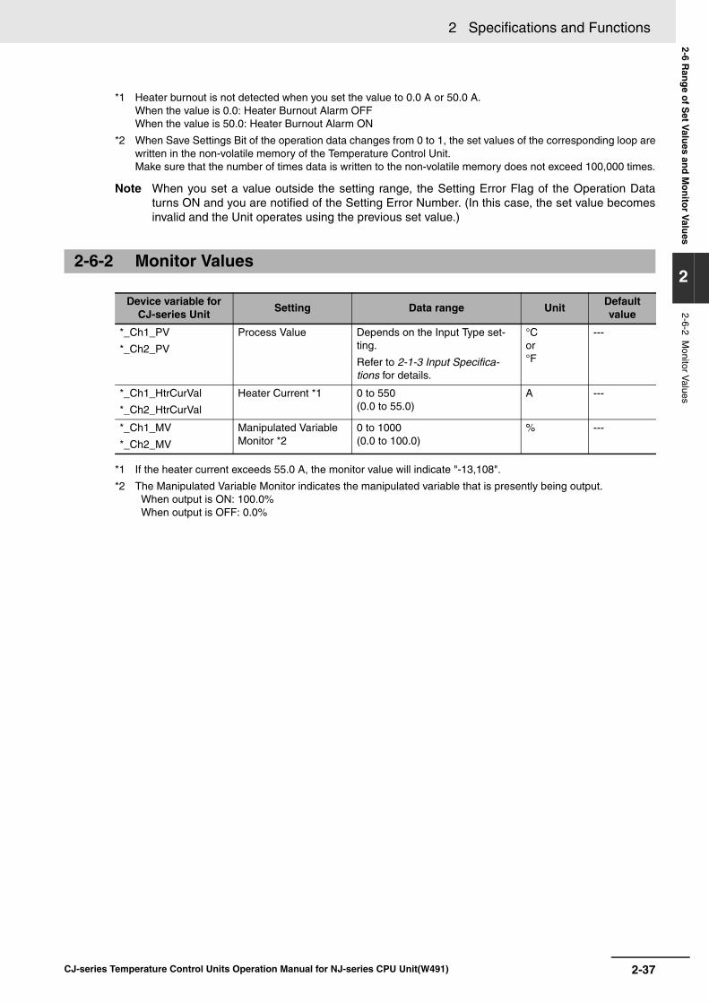
2-37
2 Specifications and Functions
CJ-series Temperature Control Units Operation Manual for NJ-series CPU Unit(W491)
2-6 Ran
ge o
f Set V
alues an
d M
on
itor V
alues
2
2-6-2 Monitor V
alues
*1 Heater burnout is not detected when you set the value to 0.0 A or 50.0 A.When the value is 0.0: Heater Burnout Alarm OFFWhen the value is 50.0: Heater Burnout Alarm ON
*2 When Save Settings Bit of the operation data changes from 0 to 1, the set values of the corresponding loop arewritten in the non-volatile memory of the Temperature Control Unit. Make sure that the number of times data is written to the non-volatile memory does not exceed 100,000 times.
Note When you set a value outside the setting range, the Setting Error Flag of the Operation Dataturns ON and you are notified of the Setting Error Number. (In this case, the set value becomesinvalid and the Unit operates using the previous set value.)
*1 If the heater current exceeds 55.0 A, the monitor value will indicate "-13,108".
*2 The Manipulated Variable Monitor indicates the manipulated variable that is presently being output. When output is ON: 100.0% When output is OFF: 0.0%
2-6-2 Monitor Values
Device variable for CJ-series Unit
Setting Data range UnitDefault value
*_Ch1_PV
*_Ch2_PV
Process Value Depends on the Input Type set-ting.
Refer to 2-1-3 Input Specifica-tions for details.
°C or °F
---
*_Ch1_HtrCurVal
*_Ch2_HtrCurVal
Heater Current *1 0 to 550(0.0 to 55.0)
A ---
*_Ch1_MV
*_Ch2_MV
Manipulated Variable Monitor *2
0 to 1000(0.0 to 100.0)
% ---

2 Specifications and Functions
2-38 CJ-series Temperature Control Units Operation Manual for NJ-series CPU Unit(W491)

3-1CJ-series Temperature Control Units Operation Manual for NJ-series CPU Unit(W491)
3
This section explains the various settings required for temperature control.
3-1 Setting the Input Type . . . . . . . . . . . . . . . . . . . . . . . . . . . . . . . . . . . . . . . . . . 3-2
3-2 Selecting the Temperature Units . . . . . . . . . . . . . . . . . . . . . . . . . . . . . . . . . 3-4
3-3 Setting the Pin 3 of the DIP Switch . . . . . . . . . . . . . . . . . . . . . . . . . . . . . . . . 3-5
3-4 Selecting the Control Operation (Forward/Reverse) . . . . . . . . . . . . . . . . . . 3-6
3-5 Selecting PID Control or ON/OFF Control . . . . . . . . . . . . . . . . . . . . . . . . . . 3-7
3-6 Setting the Control Period . . . . . . . . . . . . . . . . . . . . . . . . . . . . . . . . . . . . . . . 3-8
3-7 Setting the Set Points . . . . . . . . . . . . . . . . . . . . . . . . . . . . . . . . . . . . . . . . . . 3-9
3-8 Using ON/OFF Control . . . . . . . . . . . . . . . . . . . . . . . . . . . . . . . . . . . . . . . . . 3-10
3-9 Setting the PID Constants . . . . . . . . . . . . . . . . . . . . . . . . . . . . . . . . . . . . . . 3-11
3-10 Using the Alarm Output Function . . . . . . . . . . . . . . . . . . . . . . . . . . . . . . . . 3-15
3-11 Using the Heater Burnout Alarm . . . . . . . . . . . . . . . . . . . . . . . . . . . . . . . . 3-19
3-12 Starting and Stopping Temperature Control . . . . . . . . . . . . . . . . . . . . . . . 3-21
Settings Required for Temperature Control

3 Settings Required for Temperature Control
3-2 CJ-series Temperature Control Units Operation Manual for NJ-series CPU Unit(W491)
3-1 Setting the Input Type
Set the input type of the temperature sensor being used. There are two types of Temperature ControlUnits available: One accepts thermocouple inputs and the other accepts platinum resistance thermom-eter inputs. Both types have an "INPUT TYPE" rotary switch on the front of the Unit to set the inputtype. Set the Input Type Switch to the correct setting for sensor and temperature range being used.
The input type setting applies to all of the Unit's control loops. It is not possible to set different inputtypes for the different control loops.
Set the input type with the Input Type Switch on the front of the Unit. If this set value is changed, thenew setting will not become effective until the Unit is restarted, or the controller is reset including whenthe power is turned ON.
The diagram above shows the input type set for a K-type thermocouple with a temperature range of 0.0to 500.0C.
Thermocouple Input Types
The factory setting is 0.
Setting the Input Type Switch
Input Type Settings
Sensor TypeInput type
settingTemperature ranges
Centigrade Fahrenheit
Thermocouple K 0 200 to 1,300C 300 to 2,300F
1 0.0 to 500.0C 0.0 to 900.0F
J 2 100 to 850C 100 to 1,500F
3 0.0 to 400.0C 0.0 to 750.0F
T 4 200.0 to 400.0C 300.0 to 700.0F
L 5 100 to 850C 100 to 1,500F
6 0.0 to 400.0 C 0.0 to 750.0F
R 7 0 to 1,700C 0 to 3,000 F
S 8 0 to 1,700C 0 to 3,000 F
B 9 100 to 1,800C 300 to 3,200 F

3-3
3 Settings Required for Temperature Control
CJ-series Temperature Control Units Operation Manual for NJ-series CPU Unit(W491)
3-1 Settin
g th
e Inp
ut Typ
e
3
Platinum Resistance Thermometer Input Types
The factory setting is 0.
Sensor TypeInput type
settingTemperature ranges
Centigrade Fahrenheit
Platinum resistance thermometer
Pt100 0 200.0 to 650.0C 300.0 to 1,200.0F
JPt100 1 200.0 to 650.0C 300.0 to 1,200.0F
---- 2 to 9 Do not set 2 through 9.

3 Settings Required for Temperature Control
3-4 CJ-series Temperature Control Units Operation Manual for NJ-series CPU Unit(W491)
3-2 Selecting the Temperature Units
The Temperature Control Unit can operate in C or F. Select the desired temperature units with pin 2 ofthe DIP switch on the front of the Unit.
The temperature unit setting applies to all of the Unit's control loops. It is not possible to set differenttemperature unit settings for the different control loops.
The factory setting is OFF (C), as shown by the shading in the diagram above.
If this setting is changed, the new setting will not become effective until the Unit is restarted, or the con-troller is reset including when the power is turned ON.
1 2 3 4 5 6 7 8
ON
Pin 2
Temperature unit
C
F
Setting
OFF
ON

3-5
3 Settings Required for Temperature Control
CJ-series Temperature Control Units Operation Manual for NJ-series CPU Unit(W491)
3-3 Settin
g th
e Pin
3 of th
e DIP
Sw
itch
3
3-3 Setting the Pin 3 of the DIP Switch
Set pin 3 (Data storage/display format) of the DIP switch to ON. (The factory setting is OFF.)
If this setting is changed, the new setting will not become effective until the Unit is restarted, or the con-troller is reset including when the power is turned ON.
1 2 3 4 5 6 7 8
ON
Pin 3
Data storage/display format
Do not set.
16-bit binary
Setting
OFF
ON

3 Settings Required for Temperature Control
3-6 CJ-series Temperature Control Units Operation Manual for NJ-series CPU Unit(W491)
3-4 Selecting the Control Operation (Forward/Reverse)
With forward operation (cooling), the manipulated variable is increased as the PV increases. Withreverse operation (heating), the manipulated variable is increased as the PV decreases.
For example, when heating control is being performed and the process value (PV) is lower than the setpoint (SP), the manipulated variable is increased proportionally as the difference between the PV andSP increases. Consequently, heating control uses "reverse operation" and cooling control uses "forwardoperation." The factory setting is reverse operation (heating).
Set reverse operation or forward operation with loops 1 and 2.
Setting Loop 1 to Reverse Operation and Loop 2 to Forward OperationIf pin 4 is turned OFF and pin 5 is turned ON, loop 1 will be set for reverse operation (heating) andloop 2 will be set for forward operation (cooling).
The following diagram shows pins 4 and 5 set to their factory settings (OFF), which sets reverseoperation (heating) for all loops.
If this setting is changed, the new setting will not become effective until the Unit is restarted, or thecontroller is reset including when the power is turned ON.
The factory setting is OFF.
Forward (Cooling)/Reverse (Heating)
Setting the Control Operation (Pins 4 and 5)
100%
0%
100%
0%
Low temperature
SV High temperature
Forward operation
Low temperature
SV High temperature
Reverse operation
Manipulated variable Manipulated variable
1 2 3 4 5 6 7 8
ON
Pins 4 and 5
Control Operation
Reverse
Forward
Setting
OFF
ON

3-7
3 Settings Required for Temperature Control
CJ-series Temperature Control Units Operation Manual for NJ-series CPU Unit(W491)
3-5 Selectin
g P
ID C
on
trol o
r ON
/OF
F C
on
trol
3
3-5 Selecting PID Control or ON/OFF Control
A switch on the front of the Unit (pin 6 of the DIP switch) selects whether the Temperature Control Unituses ON/OFF control or PID control with 2 degrees of freedom.
The control method setting applies to all of the Unit's control loops. It is not possible to set different con-trol method settings for the different control loops.
If the control method setting is changed during operation, the new setting will not become effective untilthe power is turned OFF and ON again.
The factory setting is OFF (PID control), as shown in the diagram above.
If this setting is changed, the new setting will not become effective until the Unit is restarted or the con-troller is reset, including when the power is turned ON.
PID Control with Two Degrees of FreedomWith PID control, it is necessary to set the proportional band (P), integral time (I), and derivative time(D). These settings can be made automatically with autotuning or manually. Refer to 3-9 Setting thePID Constants for more details on the PID constants.
ON/OFF ControlWith ON/OFF control, the control output will be ON when the PV is below the SV. The control outputwill be OFF when the PV is at or above the SV. (This is the operation when the Unit is set for reverseoperation. This operation will work in the opposite way for forward operation.)
Setting the Control Method (Pin 6)
1 2 3 4 5 6 7 8
ON
Pin 6
Control method
PID control
ON/OFF control
Setting
OFF
ON

3 Settings Required for Temperature Control
3-8 CJ-series Temperature Control Units Operation Manual for NJ-series CPU Unit(W491)
3-6 Setting the Control Period
• This setting determines the output period (control period) for PID control. System control will improvewith a shorter control period, but if you are using relays for heater control, we recommend setting acontrol period of at least 20 s to increase the relay's lifetime. If necessary, the control period can beadjusted during trial operation.
• Set the control period in the device variables for CJ-series Unit Loop 1 and Loop 2 Control Period(*_Ch1_CtlPrdCfg, *_Ch2_CtlPrdCfg). (See the following table.) The standard setting is 2 s, but thefactory setting is 20 s.
• Each control loop has a separate control period setting.
• Setting the Loop 1 Control Period to 2 s
Set *_Ch1_CtlPrdCfg to 2.
Variable name Type Name Function
*_Ch1_CtlPrdCfg UINT Loop 1 Control Period Output Period in PID Control
*_Ch2_CtlPrdCfg UINT Loop 2 Control Period Output Period in PID Control

3-9
3 Settings Required for Temperature Control
CJ-series Temperature Control Units Operation Manual for NJ-series CPU Unit(W491)
3-7 Settin
g th
e Set P
oin
ts
3
3-7 Setting the Set Points
Set the set point (SP) in the device variables for CJ-series Unit Loop 1 and 2 Set point(*_Ch1_SetPointCfg, *_Ch2_SetPointCfg). (See the following table.)
Example) To change the loop 1 Set point from 0 °C to 200 °C, set *_Ch1_SetPointCfg to 200.
Changing the set point is not enough to start temperature control, it is also necessary for theStop Bit for that loop to be OFF. Refer to 3-12 Starting and Stopping Temperature Control fordetails.
Variable name Type Name Function
*_Ch1_SetPointCfg INT Loop 1 Set point Set the set point of loop 1.
*_Ch2_SetPointCfg INT Loop 2 Set point Set the set point of loop 2.

3 Settings Required for Temperature Control
3-10 CJ-series Temperature Control Units Operation Manual for NJ-series CPU Unit(W491)
3-8 Using ON/OFF Control
With ON/OFF control, you set a set point in advance. During reverse operation, the Temperature Con-troller will turn OFF the control output when the set point is reached. When the control output goes OFF,the system temperature will begin to drop and the control output will be turned ON again when the sys-tem temperature falls below the set point. This ON/OFF operation is repeated around the set point.
The control sensitivity setting determines how far the system temperature has to fall below the set pointbefore the control output is turned ON again. Also, the control operation setting determines whether theUnit operates with forward operation (cooling) or reverse operation (heating). With forward operation,the manipulated variable increases as the PV increases; with reverse operation, the manipulated vari-able decreases as the PV increases.
Pin 6 of the DIP switch on the front of the Unit selects whether the Temperature Control Unit usesON/OFF control or PID control with 2 degrees of freedom. The Unit will use PID control if pin 6 is OFF;it will use ON/OFF control if pin 6 is ON. The factory setting is PID control.
In ON/OFF control, the ON and OFF switching creates a stable hysteresis loop. The width of thehysteresis loop is called the control sensitivity.
Set the control method, set point, and control sensitivity for the use of ON/OFF control.
In this example, ON/OFF control is used for loop 1. The set point is 200C and the control sensitivity is2C.
• Turn ON pin 6 of the DIP switch on the front of the Unit. (The new setting will be read when the Unit isrestarted or the controller is reset, including when the power is turned ON.)
• Set device variable for CJ-series Unit Loop 1 Set point (*_Ch1_SetPointCfg) to 200.See 3-7 Setting the Set Points for details.
• Set device variable for CJ-series Unit Loop 1 Control Sensitivity (*_Ch1_CtlHystrsCfg) to 20.
ON/OFF Control Operation
Control Sensitivity
Example Settings
Variable name Type Name Function
*_Ch1_CtlHystrsCfg UINT Loop 1 Control Sensitivity Enabled only during ON/OFF control.
*_Ch2_CtlHystrsCfg UINT Loop 2 Control Sensitivity Enabled only during ON/OFF control.
ON
OFF PV
Control sensitivity (heating)
Set point

3-11
3 Settings Required for Temperature Control
CJ-series Temperature Control Units Operation Manual for NJ-series CPU Unit(W491)
3-9 Settin
g th
e PID
Co
nstan
ts
3
3-9 Setting the PID Constants
The autotuning (AT) function can be used to automatically calculate the optimal PID constants for theset point during operation. This Temperature Control Unit uses the limit cycle method, which deter-mines the controlled system's characteristics by forcibly changing the manipulated variable. Autotuningcannot be started if the Unit is stopped or using ON/OFF control operation.
Starting Autotuning• To start autotuning, turn the device variables for CJ-series Unit Loop 1 and 2 Start AT Bit
(*_Ch1_StartATCmd, *_Ch2_StartATCmd) from 0 to 1.
• When autotuning is completed, you must replace the current PID constants with the calculatedPID constants in order for the Unit to operate with the calculated PID constants. The Unit storesthe calculated PID constants in the Read PID Constants in the Operating Parameters and turnsON the PID Constants Calculated Flag at the same time. Use this flag as an input condition in theCPU Unit's user program and transfer the read PID constants from the Operating Parameters tothe word in the Operating Parameters where the Setting PID constants are stored.
After the PID constants have been transferred, turn the Change PID Constants Bit from 0 to 1.Toggling this control bit causes the Temperature Controller's PID constants to be refreshed withthe new Setting PID constants.
Read PID Constant
Setting PID Constant
Stopping Autotuning• To stop autotuning, change device variables for CJ-series Unit Loop 1 and 2 Stop AT Bit
(*_Ch1_StopATCmd, *_Ch2_StopATCmd) from 0 to 1.
• Only the Stop Bit and Stop AT Bit settings can be changed while autotuning is being executed.Settings changed during autotuning will be enabled when autotuning is completed.
• If the Stop Bit is turned ON while autotuning is being executed, autotuning will be interrupted andoperation will stop. Autotuning will not restart when operation is restarted with the Stop Bit.
Setting PID Constants with Autotuning
Variable name Type Name Function
*_Ch1_ProportionalBandSta UINT Loop 1 Proportional Band for Monitor ---
*_Ch2_ProportionalBandSta UINT Loop 2 Proportional Band for Monitor ---
*_Ch1_IntgTmSta UINT Loop 1 Integral Time for Monitor ---
*_Ch2_IntgTmSta UINT Loop 2 Integral Time for Monitor ---
*_Ch1_DerivativeTmSta UINT Loop 1 Derivative Time for Monitor ---
*_Ch2_DerivativeTmSta UINT Loop 2 Derivative Time for Monitor ---
Variable name Type Name Function
*_Ch1_ProportionalBandCfg UINT Loop 1 Proportional Band ---
*_Ch2_ProportionalBandCfg UINT Loop 2 Proportional Band ---
*_Ch1_IntgTmCfg UINT Loop 1 Integral Time ---
*_Ch2_IntgTmCfg UINT Loop 2 Integral Time ---
*_Ch1_DerivativeTmCfg UINT Loop 1 Derivative Time ---
*_Ch2_DerivativeTmCfg UINT Loop 2 Derivative Time ---

3 Settings Required for Temperature Control
3-12 CJ-series Temperature Control Units Operation Manual for NJ-series CPU Unit(W491)
Set "Proportional Band (P)", "Integral Time (I)" and "Derivative Time (D)" of the Setting PID Constantsfor the use of manually set PID constants.
Additional Information
• When you already know the system's control characteristics, set the PID constants directly toadjust the control characteristics. Set the three PID constants: The proportional band (P), inte-gral time (I), and derivative time (D).
• The Unit will operate with basic proportional operation if the integral time (I) and derivative time(D) are set to 0. If the factory settings are used, the proportional band will produce a manipu-lated variable of 0.0% at the set point.
ProcedureIn this example, autotuning is executed for loop 1 and loop 1 operates using PID control with twodegrees of freedom.
First, execute Autotuning (AT).
1 Start autotuning by turning the device variable for CJ-series Unit Loop 1 Start AT Bit
(*_Ch1_StartATCmd) from 0 to 1.
Next, perform PID constants calculation.
2 When autotuning is completed, the calculated PID constants will be stored in the Read PID
Constants.At the same time, the Loop 1 PID Constants Calculated Flag (*_Ch1_PIDCalcFlg) will be turnedON. Use this bit as an input condition in the CPU Unit's user program and transfer the Read PIDConstants to Setting PID Constants.
3 After the PID constants have been transferred to the output area by the user program, turn the
Loop 1 change PID Constants Bit (*_Ch1_ChgPIDCmd) from 0 to 1.The Temperature Control Unit will read the Setting PID Constants.The PID Constants Calculated Flag (*_Ch1_PIDCalcFlg) will be turned from 1 to 0 automaticallywhen you turn the Change PID Constants Bit (*_Ch1_ChgPIDCmd) from 0 to 1.Refer to A-4 Sample Programming for an example user program that performs the steps out-lined above.
Setting PID Constants Manually
Example PID Control Application

3-13
3 Settings Required for Temperature Control
CJ-series Temperature Control Units Operation Manual for NJ-series CPU Unit(W491)
3-9 Settin
g th
e PID
Co
nstan
ts
3
Timing Chart
Additional Information
Effects of Changes to the PID Constants
The following tables show the effects on the PV when each PID constant is changed (increasedor decreased.)
• Changing P (The Proportional Band)
• Changing I (The Integral Time)
Increasing P It takes longer to reach the set point (SP), but the process value (PV) does not overshoot.
Decreasing P The PV overshoots and there is hunting, but the PV reaches the SP quickly.
Increasing I It takes longer to reach the SP, but hunting, overshooting and undershooting are reduced.
Decreasing I Overshooting and undershoot-ing occur. Hunting occurs. The PV rises quickly.
Start AT Bit
PID Constants Calculated Flag(System-controlled.)
Change PID Constants Bit(User-controlled.)
Setting PID Constant
Setting PID Constant PID constants (user settings)
Output area data read to the CJ1W-TC@@@ Unit's RAM by I/O refreshing.
Nothing is read to the Unit's RAM during this interval.
Output area data read to the CJ1W-TC@@@ Unit's RAM by I/O refreshing.
PID constants automatically calculated by autotuning
Use the PID Constants Calculated Flag as an input condition to trigger the transfer of the read PID constant in the Operating Parameters automatically calculated with AT to the setting PID constant in the Operating Parameters.
Contains the PID constants calculated by autotuning.
Reflects Setting PID Constant (transferred PID constants calcu-lated automatically by AT). (This starts operation.)
Reflects Setting PID Constant (this starts operation).
Set to 1 by the system after calculations are completed.
AT in progressThe PID constants haven't been refreshed from the CPU Unit if this bit is ON.Automatic
calculations completed.
When this bit goes ON, the PID Con-stants Calculated Flag is unlatched and goes OFF.
1
0
1
0
1
0
SP
SP
SP
SP

3 Settings Required for Temperature Control
3-14 CJ-series Temperature Control Units Operation Manual for NJ-series CPU Unit(W491)
• Changing D (The Derivative Time)
Increasing D Overshooting, undershooting, and the set time are reduced, but hunting will occur from small changes in the system itself.
Decreasing D Overshooting and undershoot-ing are increased. It takes time to return to the SP.
SP
SP

3-15
3 Settings Required for Temperature Control
CJ-series Temperature Control Units Operation Manual for NJ-series CPU Unit(W491)
3-10 Usin
g th
e Alarm
Ou
tpu
t Fu
nctio
n
3
3-10 Using the Alarm Output Function
This section explains the alarm modes, standby sequence, and alarm values.
There are two alarm outputs for each loop and any of the following nine alarm modes can be selectedfor each alarm's operation.
To use the alarm output function, set a value in the Loop 1, 2 Alarm 1 Mode and Alarm 2 Mode(*_AlmMd) of the device variable for CJ-series Unit. Set the Alarm Mode for each loop.
If the alarm mode setting is changed, the new setting will not become effective until the controller isreset or the Unit is restarted. Always reset the controller or restart the Unit after changing the alarmmode.
Alarm ModesIn the following diagrams, the "X" indicates the alarm SV. The factory setting is "0."
Setting the Alarm Mode (Initialization Data)
Setting Alarm mode Alarm output function
Alarm SV (X) is positive Alarm SV (X) is negative
0 No alarm Output OFF
1 Upper and lower-limit alarm Always ON
2 Upper-limit alarm
3 Lower-limit alarm
4 Upper and lower-limit range alarm
Always OFF
5 Upper and lower-limit alarm with standby sequence
Always OFF
6 Upper-limit alarm with standby sequence
7 Lower-limit alarm with standby sequence
8 Absolute-value upper-limit alarm
9 Absolute-value lower-limit alarm
ONOFF
X X
SP
ONOFF
X
SP
ONOFF
X
SP
ONOFF
X
SP
ONOFF
X
SP
ONOFF
X
SP
X
ONOFF
X
SP
X
ONOFF
X
SPONOFF
X
SP
ONOFF
X
SPONOFF
X
SP
ONOFF
X
0
ONOFF
X
0
ONOFF
X
0
ONOFF
X
0

3 Settings Required for Temperature Control
3-16 CJ-series Temperature Control Units Operation Manual for NJ-series CPU Unit(W491)
The hysteresis setting controls the ON/OFF switching of the alarm output, as shown in the following dia-gram. This setting can be changed in the Initialization Data words allocated in the DM Area to the Tem-perature Control Unit.
Set device variables for CJ-series Unit "Alarm 1 Hysteresis" (*_Ch1_AL1HystrsCfg,*_Ch2_AL1HystrsCfg) and "Alarm 2 Hysteresis" (*_Ch1_AL2HystrsCfg, *_Ch2_AL2HystrsCfg) inde-pendently for each alarm. The standard setting is 0.2.
If the alarm hysteresis settings are changed, the new setting will not become effective until the control-ler is reset or the Unit is restarted. Always reset the controller or restart the Unit after changing thesesettings.
The Alarm SVs are indicated by "X" in the Alarm Modes table in 3-10 Using the Alarm Output Function.
Set values in device variables for CJ-series Unit "Alarm 1 SV" (*_Ch1_AL1LvlCfg, *_Ch2_AL1LvlCfg)and "Alarm 2 SV" (*_Ch1_AL2LvlCfg, *_Ch2_AL2LvlCfg).
Additional Information
About the Standby Sequence
The "standby sequence" disables the alarm output once the PV leaves the alarm range. Thealarm output will not function until the PV re-enters the alarm range.
For example with the standard "lower-limit alarm" mode, the PV is usually lower than the setpoint when the power is turned ON, so the PV is within the alarm range and the alarm outputgoes ON. If Lower-limit Alarm with Standby Sequence Mode is selected, the alarm will not beoutput until after the PV rises above the alarm SP, leaves the alarm range, and then falls belowthe alarm SP again.
Restarting the Standby Sequence
The standby sequence will be cleared once the PV leaves the alarm range, but the standbysequence will restart (reset) in the following situations:
• At the start of operation (when the controller is restarted or reset, including when the power isturned ON), when the alarm SV, input compensation values, or set point is changed
• When the alarm SV, input calculated values, or set point is changed
• When the Output OFF Flag turns OFF
Setting the Alarm Hysteresis (Initialization Data)
Setting the Alarm SVs (Operating Parameters)
ON
OFF
Alarm SV Alarm SV
ON
OFF
Upper-limit alarm
Lower-limit alarm
Alarm hysteresis Alarm hysteresis

3-17
3 Settings Required for Temperature Control
CJ-series Temperature Control Units Operation Manual for NJ-series CPU Unit(W491)
3-10 Usin
g th
e Alarm
Ou
tpu
t Fu
nctio
n
3
Summary of Alarm Operation
The following timing chart shows the operation of alarms with a standby sequence. In this exam-ple, the alarm mode is Upper and Lower-limit Alarm with Standby Sequence.
Alarm Mode and Alarm HysteresisThe alarm mode and alarm hysteresis for loops 1 and 2 are set as shown in the following table.
1 Set "Loop 1, 2 Alarm 1 Mode and Alarm 2 Mode" (*_AlmMd) to "16#3218".
2 Set hysteresis values in "Alarm Hysteresis" (*_Ch1_AL1HystrsCfg, *_Ch2_AL1HystrsCfg,
*_Ch1_AL2HystrsCfg and *_Ch2_AL2HystrsCfg).
3 To enable the new settings, reset the controller or restart the Unit.
Setting Alarm 1 SV of Loop 2 to 20 CSet "Loop 2 Alarm 1 SV" (*_Ch2_AL1LvlCfg) to 20.
Example Alarm Settings
Loop Alarm Alarm mode Hysteresis
Loop 1 Alarm 1 3: Lower-limit alarm 2.0C
Alarm 2 2: Upper-limit alarm 0.5C
Loop 2 Alarm 1 1: Upper and lower-limit alarm 1.0C
Alarm 2 8: Absolute-value lower-limit alarm 2.0C
Alarm mode: Upper and Lower-limit Alarm with Standby Sequence
Alarm SV(upper)
Alarm goes OFF by hysteresis
Alarm SV(lower)
Alarm output
Standby sequence cleared
Alarm goes OFF by hysteresis
Output disabled by standby sequence

3 Settings Required for Temperature Control
3-18 CJ-series Temperature Control Units Operation Manual for NJ-series CPU Unit(W491)
Summary of Alarm Output Function Settings
Variable name Type Name Function
*_AlmMd WORD Loop 1, 2 Alarm 1 Mode and Alarm 2 Mode
Set the Alarm 1 Mode and Alarm 2 Mode of loop 1 and loop 2.
0: No alarm
1: Upper and lower-limit alarm
2: Upper-limit alarm
3: Lower-limit alarm
4: Upper and lower-limit range alarm
5: Upper and lower-limit alarm with standby sequence
6: Upper-limit alarm with standby sequence
7: Lower-limit alarm with standby sequence
8: Absolute-value upper-limit alarm
9: Absolute-value lower-limit alarm
*_Ch1_AL1HystrsCfg UINT Loop 1 Alarm 1 Hysteresis Set the loop 1 alarm hys-teresis.*_Ch1_AL2HystrsCfg UINT Loop 1 Alarm 2 Hysteresis
*_Ch2_AL1HystrsCfg UINT Loop 2 Alarm 1 Hysteresis Set the loop 2 alarm hys-teresis.*_Ch2_AL2HystrsCfg UINT Loop 2 Alarm 2 Hysteresis
*_Ch1_AL1LvlCfg INT Loop 1 Alarm 1 SV Set the loop 1 detection level.*_Ch1_AL2LvlCfg INT Loop 1 Alarm 2 SV
*_Ch2_AL1LvlCfg INT Loop 2 Alarm 1 SV Set the loop 2 detection level.*_Ch2_AL2LvlCfg INT Loop 2 Alarm 2 SV

3-19
3 Settings Required for Temperature Control
CJ-series Temperature Control Units Operation Manual for NJ-series CPU Unit(W491)
3-11 Usin
g th
e Heater B
urn
ou
t Alarm
3
3-11 Using the Heater Burnout Alarm
• Follow this procedure to detect heater burnout (an open heating wire).
1 Pass the heater wire through the hole in the Current Transformer (CT). Refer to Current Trans-
former (CT) Ratings in 2-1 Specifications and A-1 Dimensions for details on the specifications,model numbers, and dimensions.
2 When current flows through the heater wire, it induces an AC current in the Current Transformer
(CT) that is proportional to the current in the heater wire. The current flowing through the heatercan be determined from the current induced in the CT.
3 The current will drop if there is a heater burnout and the heater burnout alarm (HB output) will
be turned ON if the current falls below the preset heater burnout current.
4 The HB output is a latched output. To release the latch (i.e., turn OFF the HB output), either set
the heater burnout current to 0.0, reset the controller, or restart the Temperature Control Unit.
Note 1 Do not use any CT other than the OMRON E54-CT1 or E54-CT3 Current Transformer.
2 Set the desired heater burnout detection current in the Heater Burnout Current word. Thevalue in the Heater Current Monitor word can be used to check the CT's current.
3 Set the heater burnout current to 0.0 if you are not using the heater burnout detection function.
4 The heater burnout current is set independently for each loop.
• Connect the CT and pass the heater wire through the CT in advance.
• Turn ON the heater's power supply before the Temperature Control Unit or turn ON both at the sametime. The heater burnout alarm will be output if the heater's power supply is turned ON after the Tem-perature Control Unit.
• Temperature control will continue even if a heater burnout is detected, so that the Unit can continuecontrolling heaters that have not burned out.
• Heater burnout detection will operate when the control output has been ON continuously for morethan 200 ms.
• Sometimes the heater's rated current does not match the current that actually flows through theheater. Use the heater current monitor to check the current during actual use.
• Heater burnout detection will be unstable if there is only a small difference between the normal cur-rent and heater burnout current. For stable operation, set a minimum difference of 1.0 A with heatersdrawing less than 10.0 A or a minimum difference of 2.5 A with heaters drawing 10.0 A or more.
Heater Burnout Detection
Operating Conditions
Heater wire
To the CT terminals
CT

3 Settings Required for Temperature Control
3-20 CJ-series Temperature Control Units Operation Manual for NJ-series CPU Unit(W491)
• The heater burnout detection function cannot be used if the heater is being controlled with the posi-tion control method or cycle control method. Also, the heater burnout detection function cannot beused with three-phase heaters.
Note To detect heater burnout in a three-phase heater, use a K2CU-F@@A-@GS (with gate input ter-minals). Refer to the catalog for more details.
• Use the following equation to calculate the average of the normal current and the current with aheater burnout:
• If more than one heater is connected through the CT, set the heater burnout current to the currentinduced when the heater with the smallest current consumption is burned out. If the heaters all con-sume the same current, set the heater burnout current to the current induced when one of the heat-ers is burned out.
• The difference between the normal current and the heater burnout current must meet the followingminimum levels:
Heaters drawing less than 10.0 A:Normal current current with heater burnout 1.0 A(Operation will be unstable with a difference less than 1.0 A.)
Heaters drawing 10.0 A or more:Normal current current with heater burnout 2.5 A(Operation will be unstable with a difference less than 2.5 A.)
• The set value range for the heater burnout current is 0.1 to 49.9 A. Heater burnout will not bedetected if the heater burnout current is set to 0.0 or 50.0 A. The heater burnout alarm will be OFF ifthe heater burnout current is set to 0.0; it will be ON if the heater burnout current is set to 50.0.
• The total heater current during normal operation must not exceed 50.0 A.
Determining the Heater Burnout Current
Example Applications
SV =Current in normal operation + current after heater burnout
2
Heater
1 kW 3
CT
200 VAC
Control output Example 1:A single 1-kW 200-VAC heater is controlled through OUT1.
Normal current = 1,000200
= 5 A (< 10 A)
Current when control output is OFF = 0 A
5 + 02
= 2.5 ASV =
Normal current - control-OFF current = 5 - 0 = 5 A(Operation will be stable with difference 1.0 A.)
Heaters
CT
200 VAC
Control output Example 2:Three 1-kW 200-VAC heaters are controlled through OUT2.
Normal current = 1,000 3
200= 15 A (10 A)
Current with 1 burnout =
15 + 102
= 12.5 ASV =
Normal current - control-OFF current = 15 - 10 = 5 A(Operation will be stable with difference 2.5 A.)
1,000 2200
= 10 A
1 kW

3-21
3 Settings Required for Temperature Control
CJ-series Temperature Control Units Operation Manual for NJ-series CPU Unit(W491)
3-12 Startin
g an
d S
top
pin
g Tem
peratu
re Co
ntro
l
3
3-12 Starting and Stopping Temperature Control
To start temperature control for a loop that has been stopped, turn device variables for CJ-series Unit"Stop Bit" (*_Ch1_StopCtlCmd and *_Ch2_StopCtlCmd) to OFF.
To stop temperature control for the loop, turn ON the Stop Bit.
• The factory setting of the bits is OFF (running).
Starting Loop 1 and Stopping Loop 2• To start control in loop 1 and stop control in loop 2, turn OFF "Loop 1 Stop Bit"
(*_Ch1_StopCtlCmd) and turn ON "Loop 2 Stop Bit" (*_Ch2_StopCtlCmd).

3 Settings Required for Temperature Control
3-22 CJ-series Temperature Control Units Operation Manual for NJ-series CPU Unit(W491)

4-1CJ-series Temperature Control Units Operation Manual for NJ-series CPU Unit(W491)
4
This section explains how to use the input compensation value.
4-1 Shifting the Input Value (Input Compensation) . . . . . . . . . . . . . . . . . . . . . . 4-2
4-2 Recovering from Sensor Not Connected Errors . . . . . . . . . . . . . . . . . . . . . 4-3
Optional Settings

4 Optional Settings
4-2 CJ-series Temperature Control Units Operation Manual for NJ-series CPU Unit(W491)
4-1 Shifting the Input Value (Input Compensation)
• The input value is shifted by the "input compensation value" for all points in the sensor's range. Forexample, if the input compensation value is set to 1.2C and the original process value is 200C, thevalue after compensation will be 201.2C.
• The factory setting of the input compensation value is 0.0 for all loops.
Example Application
1 In Figure 1, the temperature sensor is some distance from the workpiece that is being controlled
and the reading from the temperature sensor must be adjusted to reflect the actual temperatureat the workpiece. (The reading from thermometer (B) shows the true temperature at the work-piece (C).)
2 The input compensation value is just the difference between the workpiece's temperature (B)
and the Temperature Control Unit's reading (A). Figure 2 shows the process values before andafter compensation.
Input Compensation Value = Workpiece's temp. (B) - Unit's reading (A)
3 After setting the input compensation value, compare the temperature displayed on the Unit (A)
with the temperature indicated by thermometer (B). The input compensation value is correct ifthe two readings are approximately equal.
Temperature
Upper limit
100% FS
After compensation
0
Input compensation value
Before compen-sation
Input
(C) Workpiece temp.
(D) Temperature sensor
(A) Temperature Control Unit
Unit's temperature reading (A)
(B) Thermometer
100
Furnace
Temperature after compensation (e.g., 120C)
Figure 2. Compensation Graph of 1-point Compensation
Temperature before compensation (e.g., 110C)
Input compensation value (e.g., 10C)
After compensation
Before compensation
Thermometer reading (B)
Figure 1. Input Compensation Configuration
SP region (e.g., 120C)
Lower limit input compensation value (e.g., 10C)

4-3
4 Optional Settings
CJ-series Temperature Control Units Operation Manual for NJ-series CPU Unit(W491)
4-2 Recoverin
g fro
m S
enso
r No
t Co
nn
ected E
rrors
4
4-2 Recovering from Sensor Not Connected Errors
If a sensor is not connected for any loop, a sensor error will occur and the ERC indicator on the frontpanel of the Unit will light. When necessary, the control and alarm functions for any loop can be dis-abled. The status will be as follows.
• The ERC indicator will not light to indicate sensor errors for the loop. (Refer to 5-1 Error and AlarmProcessing.)
• Control will not be performed for the loop.
• Alarms will not be given for the loop.
• Temperatures will be input for the loop.
To disable the control and alarm functions of a certain loop, set both Alarm Mode 1 and Alarm Mode 2of each loop of device variables for CJ-series Unit "Loop 1, 2 Alarm 1 Mode and Alarm 2 Mode"(*_AlmMd) to 16#F (i.e.,16#FF).
Example) To disable loop 2, set "Loop 1, 2 Alarm 1 Mode and Alarm 2 Mode" (*_AlmMd) to 16#FF. (Inthis case, Alarm Mode 1 and Alarm Mode 2 of loop 1 are set to 0.)
DM Area addressBits
15 14 13 12 11 10 09 08 07 06 05 04 03 02 01 00
*_AlmMd Loop 1 Loop 2
Alarm mode 1 Alarm mode 2 Alarm mode 1 Alarm mode 2

4 Optional Settings
4-4 CJ-series Temperature Control Units Operation Manual for NJ-series CPU Unit(W491)

5-1CJ-series Temperature Control Units Operation Manual for NJ-series CPU Unit(W491)
5
This section provides information on troubleshooting and error processing.
5-1 Error and Alarm Processing . . . . . . . . . . . . . . . . . . . . . . . . . . . . . . . . . . . . . 5-2
5-2 Troubleshooting . . . . . . . . . . . . . . . . . . . . . . . . . . . . . . . . . . . . . . . . . . . . . . 5-10
5-3 Event Logs . . . . . . . . . . . . . . . . . . . . . . . . . . . . . . . . . . . . . . . . . . . . . . . . . . 5-165-3-1 Overview of the Event Logs . . . . . . . . . . . . . . . . . . . . . . . . . . . . . . . . . . . . . . 5-16
5-3-2 Error Table . . . . . . . . . . . . . . . . . . . . . . . . . . . . . . . . . . . . . . . . . . . . . . . . . . . 5-175-3-3 Error Descriptions . . . . . . . . . . . . . . . . . . . . . . . . . . . . . . . . . . . . . . . . . . . . . 5-18
Error and Alarm Processing

5 Error and Alarm Processing
5-2 CJ-series Temperature Control Units Operation Manual for NJ-series CPU Unit(W491)
5-1 Error and Alarm Processing
The ERC Indicator or ERH Indicator will light if an alarm or error occurs in the Temperature Control Unit.
Identifying Errors with the Indicators
Indicator Name Color Status Meaning
RUN RUN Indicator Green Lit The Temperature Control Unit is operating normally.
Not lit The Temperature Control Unit is stopped.
ERC Temperature Control Unit Error
Red Lit An error occurred in the Temperature Control Unit itself.
Not lit There is no error in the Temperature Control Unit.
ERH CPU Unit Error Red Lit An error occurred in the CPU Unit.
Not lit There is no error in the CPU Unit.
(Front of Temperature Control Unit)
RUN
ERC
ERH

5-3
5 Error and Alarm Processing
CJ-series Temperature Control Units Operation Manual for NJ-series CPU Unit(W491)
5-1 Erro
r and
Alarm
Pro
cessing
5
Use the following flowchart to identify the error when an error has occurred in the Temperature ControlUnit.
Error Processing Flowchart
Error occurred.
Is the ERC Indicator lit? Is the RUN Indicator lit?
An alarm occurred while the Unit was operating.
Refer to Alarms and Statuses Detected by the Temperature Control Unit.
Confirm that the Unit's Initialization Data is correct.
Refer to Alarms and Statuses Detected by the Temperature Control Unit.
An error occurred in the CPU Unit.
Yes
No
Yes
No
Refer to Errors Originating in the CPU Unit.
Confirm that the Unit's unit number setting is correct.
Refer to Errors Originating in the CPU Unit.
Refer to 5-2 Troubleshooting.
Is the ERH Indicator lit?Yes
No
Is the RUN Indicator lit?Yes
No

5 Error and Alarm Processing
5-4 CJ-series Temperature Control Units Operation Manual for NJ-series CPU Unit(W491)
ERC indicator lights when an alarm occurs detected by the Temperature Control Unit itself. At this time,an alarm flag of the device variable for CJ-series Unit (for operation) is stored.
Alarms and Statuses Detected by the Temperature Control Unit
BitsName of device variable for
CJ-series UnitType R/W Name Function
*_Ch1_StaWd WORD R Loop 1 Status Bits serve the functions described below.
Each bit is defined with a BOOL data type variable.
Bit 00: Loop 1 AL2 Flag
Bit 01: Loop 1 AL1 Flag
Bit 02: Loop 1 HB Flag
Bit 03: Loop 1 AT Flag
Bit 04: Loop 1 Control Output Flag
Bit 05:
Bit 06:
Bit 07:
Bit 08: Loop 1 Stop Flag
Bit 09: Loop 1 Setting Error Flag
Bit 10: Loop 1 PID Constants Calculated Flag
Bit 11: Loop 1 Standby Flag
Bit 12: Loop 1 Cold Junction Sensor Error
Bit 13: Loop 1 CT Overflow Flag
Bit 14: Loop 1 Sensor Error Flag
Bit 15: Loop 1 Save Completed Flag
00 *_Ch1_AL2Flg BOOL R Loop 1 AL2 Flag
The value becomes 1 when the temperature is within the alarm range set with the input value of loop 1.
The value becomes 0 when outside the alarm range.
01 *_Ch1_AL1Flg BOOL R Loop 1 AL1 Flag
The value becomes 1 when the temperature is within the alarm range set with the input value of loop 1.
The value becomes 0 when outside the alarm range.
02 *_Ch1_HBFlg BOOL R Loop 1 HB Flag The value becomes 1 when the heater cur-rent detection value falls below the Heater Burnout Current.
03 *_Ch1_ATFlg BOOL R Loop 1 AT Flag The value becomes 1 during Autotuning (AT) of loop 1.
The value becomes 0 when Autotuning (AT) stops or finishes.
04 *_Ch1_CtlOutFlg BOOL R Loop 1 Control Output Flag
The value becomes 1 during output of loop 1 Control Output.
08 *_Ch1_StopFlg BOOL R Loop 1 Stop Flag
The value becomes 0 when temperature control of loop 1 executes and 1 when con-trol stops.
09 *_Ch1_SetErr BOOL R Loop 1 Setting Error Flag
The value becomes 1 when there is an error in the set value set as a device variable for CJ-series Unit.

5-5
5 Error and Alarm Processing
CJ-series Temperature Control Units Operation Manual for NJ-series CPU Unit(W491)
5-1 Erro
r and
Alarm
Pro
cessing
5
10 *_Ch1_PIDCalcFlg BOOL R Loop 1 PID Constants Cal-culated Flag
The value becomes 1 when PID constants calculated by the Temperature Control Unit with AT are updated.
When this bit is 1, PID constants of the OUT Area of Operating Parameters are not imported into the Temperature Control Unit.When the bit is 0, PID constants of the OUT Area of Operating Parameters are imported into the Temperature Control Unit.
11 *_Ch1_StbyFlg BOOL R Loop 1 Standby Flag
The value becomes 1 when the Temperature Control Unit is waiting for I/O refreshing after the Controller is reset or the Unit is restarted.
12 *_Ch1_CJErr BOOL R Loop 1 Cold Junction Sen-sor Error
The value becomes 1 when:
• Cold junction sensor error occurs.
13 *_Ch1_CTOvfFlg BOOL R Loop 1 CT Overflow Flag
The value becomes 1 when the heater cur-rent of the CT (current detector) exceeds 55.0 A.
14 *_Ch1_SensErr BOOL R Loop 1 Sensor Error Flag
The value becomes 1 when:
• Sensor is not connected to loop 1.
• Sensor of loop 1 disconnects.• Input temperature exceeds the measure-
ment temperature range.
15 *_Ch1_SaveFlg BOOL R Loop 1 Save Completed Flag
The value becomes 1 when you select save loop 1 (change from 0 to 1) and data is writ-ten to the non-volatile memory.
This flag initializes to 0 when Loop 1 Save changes from 1 to 0 (however, the value is 0 immediately after a controller reset).
*_Ch2_StaWd WORD R Loop 2 Status Bits serve the functions described below.
Each bit is defined with a BOOL data type variable.
Bit 00: Loop 2 AL2 Flag
Bit 01: Loop 2 AL1 Flag
Bit 02: Loop 2 HB Flag
Bit 03: Loop 2 AT Flag
Bit 04: Loop 2 Control Output Flag
Bit 05:
Bit 06:
Bit 07:
Bit 08: Loop 2 Stop Flag
Bit 09: Loop 2 Setting Error Flag
Bit 10: Loop 2 PID Constants Calculated Flag
Bit 11: Loop 2 Standby Flag
Bit 12: Loop 2 Cold Junction Sensor Error
Bit 13: Loop 2 CT Overflow Flag
Bit 14: Loop 2 Sensor Error Flag
Bit 15: Loop 2 Save Completed Flag
BitsName of device variable for
CJ-series UnitType R/W Name Function

5 Error and Alarm Processing
5-6 CJ-series Temperature Control Units Operation Manual for NJ-series CPU Unit(W491)
00 *_Ch2_AL2Flg BOOL R Loop 2 AL2 Flag
The value becomes 1 when the temperature is within the alarm range set with the input value of loop 2.
The value becomes 0 when outside the alarm range.
01 *_Ch2_AL1Flg BOOL R Loop 2 AL1 Flag
The value becomes 1 when the temperature is within the alarm range set with the input value of loop 2.
The value becomes 0 when outside the alarm range.
02 *_Ch2_HBFlg BOOL R Loop 2 HB Flag The value becomes 1 when the heater cur-rent detection value falls below the Heater Burnout Current.
03 *_Ch2_ATFlg BOOL R Loop 2 AT Flag The value becomes 1 during Autotuning (AT) of loop 2.
The value becomes 0 when Autotuning (AT) stops or finishes.
04 *_Ch2_CtlOutFlg BOOL R Loop 2 Control Output Flag
The value becomes 1 during output of loop 2 Control Output.
08 *_Ch2_StopFlg BOOL R Loop 2 Stop Flag
The value becomes 0 when temperature control of loop 2 executes and 1 when con-trol stops.
09 *_Ch2_SetErr BOOL R Loop 2 Setting Error Flag
The value becomes 1 when there is an error in the setting value set as a device variable for CJ-series Unit
10 *_Ch2_PIDCalcFlg BOOL R Loop 2 PID Constants Cal-culated Flag
The value becomes 1 when PID constants calculated by the Temperature Control Unit with AT are updated.
When this bit is 1, PID constants of the OUT Area of Operating Parameters are not imported into the Temperature Control Unit. When the bit is 0, PID constants of the OUT Area of Operating Parameters are imported into the Temperature Control Unit.
11 *_Ch2_StbyFlg BOOL R Loop 2 Standby Flag
The value becomes 1 when the Temperature Control Unit is waiting for I/O refreshing after the Controller is reset or the Unit is restarted.
12 *_Ch2_CJErr BOOL R Loop 2 Cold Junction Sensor Error
The value becomes 1 when:
• Cold junction sensor error occurs.
13 *_Ch2_CTOvfFlg BOOL R Loop 2 CT Overflow Flag
The value becomes 1 when the heater cur-rent of the CT (current detector) exceeds 55.0 A.
14 *_Ch2_SensErr BOOL R Loop 2 Sensor Error Flag
The value becomes 1 when:
• Sensor is not connected to loop 2.
• Sensor of loop 2 disconnects.• Input temperature exceeds the measure-
ment temperature range.
15 *_Ch2_SaveFlg BOOL R Loop 2 Save Completed Flag
The value becomes 1 when you select save loop2 (change from 0 to 1) and data is writ-ten to the non-volatile memory.
This flag initializes to 0 when Loop 2 Save changes from 1 to 0 (however, the value is 0 immediately after a controller reset).
BitsName of device variable for
CJ-series UnitType R/W Name Function

5-7
5 Error and Alarm Processing
CJ-series Temperature Control Units Operation Manual for NJ-series CPU Unit(W491)
5-1 Erro
r and
Alarm
Pro
cessing
5
These alarms indicate that an incorrect operation was performed while the Unit was operating normally.These alarms are cleared automatically when the cause of the alarm is corrected.
If pin 1 of the Temperature Control Unit's DIP Switch is OFF (stop operation when CPU Unit is in PRO-GRAM mode), the RUN Indicator will be OFF when the CPU Unit is in PROGRAM mode.
Setting Error Numbers
When there are errors in two or more settings, the setting error number with the highest priority willbe stored.
ERC Indicator Lit and RUN Indicator Lit
*_Ch1_SensErr*_Ch2_SensErr
*_Ch1_CTOvfFlg*_Ch2_CTOvfFlg
*_Ch1_SetErr*_Ch2_SetErr
*_Ch1_HBFlg*_Ch2_HBFlg
Error Sensor Error CT Overflow Setting Error Heater Burnout Alarm
Cause An input error has occurred. The heater current is above 55.0 A.
There is an error in a setting. A heater circuit has burned out.
Control status
• Control operation contin-ues (Output OFF).
• Alarm operates as if the temperature is out of range.
Control operation continues. The incorrect set value will be ignored and operation will continue with the set values retained in the Temperature Control Unit.
Control operation continues.
Processing Check for incorrect input wir-ing, disconnection, short-cir-cuit, and incorrect input type setting.
The heater current value will be correct when the current is within range.
Check the "Setting Error Number" in *_DecPointSetErrSta. Cor-rect the indicated setting.
Check the heater and repair the heater where the burnout occurred.
Setting error number
Setting name Priority
0 No incorrect settings -
1 Alarm mode 1 1
2 Alarm mode 2 2
3 Alarm 1 hysteresis 3
4 Alarm 2 hysteresis 4
5 Set point 5
6 Alarm 1 SV 6
7 Alarm 2 SV 7
8 Input compensation value 8
9 Control period 9
A Control sensitivity 10
B Proportional band 11
C Integral time 12
D Derivative time 13
E Heater burnout current 14
F Not allocated 15
Lit
RUN
ERC
ERH Not lit
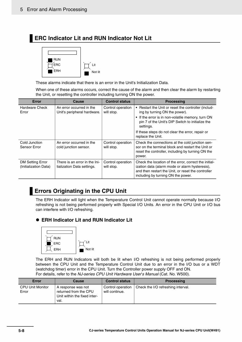
5 Error and Alarm Processing
5-8 CJ-series Temperature Control Units Operation Manual for NJ-series CPU Unit(W491)
These alarms indicate that there is an error in the Unit's Initialization Data.
When one of these alarms occurs, correct the cause of the alarm and then clear the alarm by restartingthe Unit, or resetting the controller including turning ON the power.
The ERH Indicator will light when the Temperature Control Unit cannot operate normally because I/Orefreshing is not being performed properly with Special I/O Units. An error in the CPU Unit or I/O buscan interfere with I/O refreshing.
ERH Indicator Lit and RUN Indicator Lit
The ERH and RUN Indicators will both be lit when I/O refreshing is not being performed properlybetween the CPU Unit and the Temperature Control Unit due to an error in the I/O bus or a WDT(watchdog timer) error in the CPU Unit. Turn the Controller power supply OFF and ON.For details, refer to the NJ-series CPU Unit Hardware User's Manual (Cat. No. W500).
ERC Indicator Lit and RUN Indicator Not Lit
Error Cause Control status Processing
Hardware Check Error
An error occurred in the Unit's peripheral hardware.
Control operation will stop.
• Restart the Unit or reset the controller (includ-ing by turning ON the power).
• If the error is in non-volatile memory, turn ON pin 7 of the Unit's DIP Switch to initialize the settings.
If these steps do not clear the error, repair or replace the Unit.
Cold Junction Sensor Error
An error occurred in the cold junction sensor.
Control operation will stop.
Check the connections at the cold junction sen-sor on the terminal block and restart the Unit or reset the controller, including by turning ON the power.
DM Setting Error(Initialization Data)
There is an error in the Ini-tialization Data settings.
Control operation will stop.
Check the location of the error, correct the initial-ization data (alarm mode or alarm hysteresis), and then restart the Unit, or reset the controller including by turning ON the power.
Errors Originating in the CPU Unit
Error Cause Control status Processing
CPU Unit Monitor Error
A response was not returned from the CPU Unit within the fixed inter-val.
Control operation will continue.
Check the I/O refreshing interval.
Lit
RUN
ERC
ERH Not lit
LitRUN
ERC
ERH Not lit
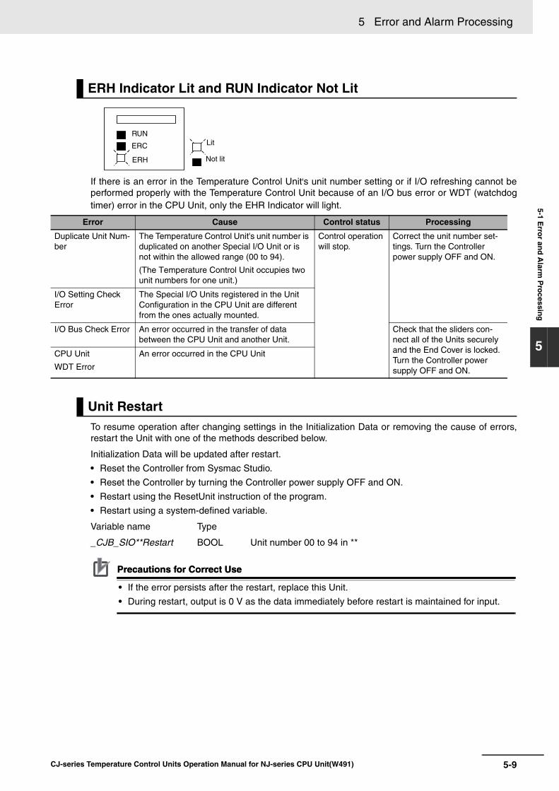
5-9
5 Error and Alarm Processing
CJ-series Temperature Control Units Operation Manual for NJ-series CPU Unit(W491)
5-1 Erro
r and
Alarm
Pro
cessing
5
If there is an error in the Temperature Control Unit's unit number setting or if I/O refreshing cannot beperformed properly with the Temperature Control Unit because of an I/O bus error or WDT (watchdogtimer) error in the CPU Unit, only the EHR Indicator will light.
To resume operation after changing settings in the Initialization Data or removing the cause of errors,restart the Unit with one of the methods described below.
Initialization Data will be updated after restart.
• Reset the Controller from Sysmac Studio.
• Reset the Controller by turning the Controller power supply OFF and ON.
• Restart using the ResetUnit instruction of the program.
• Restart using a system-defined variable.
Variable name Type
_CJB_SIO**Restart BOOL Unit number 00 to 94 in **
Precautions for Correct UsePrecautions for Correct Use
• If the error persists after the restart, replace this Unit.
• During restart, output is 0 V as the data immediately before restart is maintained for input.
ERH Indicator Lit and RUN Indicator Not Lit
Error Cause Control status Processing
Duplicate Unit Num-ber
The Temperature Control Unit's unit number is duplicated on another Special I/O Unit or is not within the allowed range (00 to 94).
(The Temperature Control Unit occupies two unit numbers for one unit.)
Control operation will stop.
Correct the unit number set-tings. Turn the Controller power supply OFF and ON.
I/O Setting Check Error
The Special I/O Units registered in the Unit Configuration in the CPU Unit are different from the ones actually mounted.
I/O Bus Check Error An error occurred in the transfer of data between the CPU Unit and another Unit.
Check that the sliders con-nect all of the Units securely and the End Cover is locked. Turn the Controller power supply OFF and ON.
CPU Unit
WDT Error
An error occurred in the CPU Unit
Unit Restart
LitRUN
ERC
ERH Not lit

5 Error and Alarm Processing
5-10 CJ-series Temperature Control Units Operation Manual for NJ-series CPU Unit(W491)
5-2 Troubleshooting
If some problem develops with the Temperature Control Unit, use the following procedure to isolate andcorrect the problem.
Check Indicators.
Check switch settings and wiring.
Check the Temperature Controller Unit's operating status with the Indicators.Follow the procedures described in 5-1 Error and Alarm Processing to isolate and correct any problems indicated by the LED Indicators.
Check the switch settings and wiring. Power Supply1. Is the power supply ON?2. Is the voltage at the terminals within the allowed range? Switches
Are the switch settings correct for the system you are using? Wiring1. Is the terminal block wiring correct?2. Is the polarity correct (not reversed)?3. Are any power lines disconnected?4. Are any of the systems wires and cables broken or shorted?
If the system checks did not reveal the source of the problem, try to isolate the problem from the symptoms using the tables on the following pages.
Troubleshoot from symptoms.

5-11
5 Error and Alarm Processing
CJ-series Temperature Control Units Operation Manual for NJ-series CPU Unit(W491)
5-2 Trou
blesh
oo
ting
5
Incorrect Measurement or No Measurement
Troubleshooting from Symptoms: Measurement Errors
Step Possible Cause Remedy
Connection The temperature sensor is connected to the wrong terminals or polarity is reversed.
Wire temperature sensor correctly.
The temperature sensor connected to the Tem-perature Control Unit is not compatible with the Unit.
Replace the temperature sensor with one that is com-patible with the Temperature Control Unit.
The temperature sensor wires are broken, short-circuited, or damaged.
Replace the temperature sensor with a good one.
No temperature sensor is connected. Connect a temperature sensor.
The compensating conductor being used is not compatible with the thermocouple.
• Directly connect a thermocouple with long lead wires.• Use a compensating conductor that is compatible
with the thermocouple.
Some equipment is connected between the ther-mocouple and Temperature Control Unit that uses metal different than the metal in the compensat-ing conductor or thermocouple.
The equipment used for connections must be made specifically for use with thermocouples.
The terminal screws are loose so there is poor contact between the wires and terminals.
Tighten the terminal screws.
The thermocouple's lead wires or the compensat-ing conductors are too long, so the resistance in the wires is affecting operation.
• Use thicker compensating conductors.
• Change the wiring location to reduce the length of the wiring.
The conductors between the temperature sensor and the Temperature Control Unit's terminals have three different conductive resistances.
Use conductors with the same resistance for the A, B, and B' terminals.
Installation Noise from electric equipment around the Tem-perature Control Unit is affecting operation.
• Move the Temperature Control Unit away from the equipment that is generating the noise.
• Install surge protectors or noise filters on the equip-ment that is generating the noise.
The temperature sensor's leads run close to power lines, so noise is being induced from the power lines.
• Separate the temperature sensor's leads from the power lines.
• Run the temperature sensor's leads in a conduit or duct separate from the one carrying the power lines.
• Do not run the temperature sensor's leads parallel to the power lines.
• Reduce the length of the temperature sensor's leads.
• Use shielded wire for the temperature sensor's leads.
The temperature sensor is installed too far from the point being controlled, so the response to temperature changes is delayed.
Install the temperature sensor in a protective tube closer to the point being controlled.
The ambient temperature where the Temperature Control Unit is installed exceeds the Unit's rat-ings.
Install the Temperature Control Unit in a location with an ambient temperature between 0 and 55C.
Wireless equipment is being used near the Tem-perature Control Unit.
Shield the Temperature Control Unit.
The temperature around the Temperature Control Unit is not uniform because of heat-generating equipment near the Unit.
Move the Temperature Control Unit to a location where it won't be affected by heat-generating equipment.
There is a draft (breeze) on the Temperature Con-trol Unit's terminal block.
Eliminate or block the draft.

5 Error and Alarm Processing
5-12 CJ-series Temperature Control Units Operation Manual for NJ-series CPU Unit(W491)
Additional Information
Here is a simple method to check the temperature sensor inputs:
With a resistance-thermometer Unit, connect a 100- resistor to the A-B temperature sensorinput terminals and short the B-B terminals. The Temperature Control Unit is operating normallyif the measured temperature is at the 0.0C or 32.0F level.
With a thermocouple Unit, short the temperature sensor input terminals. The Temperature Con-trol Unit is operating normally if the measured temperature is the temperature in the vicinity ofthe terminal block.
Temperature Does Not Rise
Settings The Input Type setting is incorrect. Set the Input Type correctly.
The Temperature Units setting is incorrect. Set the Temperature Units correctly.
The measured temperature appears to be shifted because of the Input Compensation Value setting.
Set the Input Compensation Value to 0.0.
The data storage/display format setting is incor-rect.
• Check the "data storage/display format" of pin 3 of the DIP switch and correct the user program.
• Always set pin 3 of the DIP switch to ON when con-nected with the NJ series.
The user program of the Host System is not cor-rect.
Usage There is a thermocouple input and the input ter-minals are shorted.
Connect a thermocouple.
The temperature sensor was replaced or switch settings were changed while the power was ON.
Turn the power OFF and then ON again.
Troubleshooting from Symptoms: Temperature Control Errors
Step Possible Cause Remedy
Connection The measured temperature is incorrect. Refer to Troubleshooting from Symptoms: Measurement Errors for troubleshooting directions.
There is no load connected to the control output termi-nals.
Connect a load.
The load's polarity is reversed or the load is wired to the wrong terminals.
Wire the load correctly.
The terminal screws are loose so there is poor contact between the wires and terminals.
Tighten the terminal screws.
The heater's power supply is not ON. Turn ON the heater's power supply.
The heater circuit is burned out or damaged. Replace the heater with a good one.
The heater's heat output is insufficient. • Replace the heater with one that has a higher output.
• When using two or more heaters, check whether one is burned out. Replace if necessary.
An overheating protection device is operating. Increase the overheating protection device's temperature set-ting so it is higher than the Temperature Controller Unit's set point.
Settings The forward operation/reverse operation setting is incor-rect
Correct the setting.
The PID constant settings are not correct. • Perform autotuning.
• Make the correct PID constant settings manually.
Temperature control has not been started. Start temperature control.
A cooling fan is operating. Turn OFF the cooling fan.
Step Possible Cause Remedy

5-13
5 Error and Alarm Processing
CJ-series Temperature Control Units Operation Manual for NJ-series CPU Unit(W491)
5-2 Trou
blesh
oo
ting
5
Measured Temperature Higher than Control Temperature
Step Possible Cause Remedy
Connection The measured temperature is incorrect. Refer to Troubleshooting from Symptoms: Measurement Errors for troubleshooting directions.
The load is connected to the wrong control loop, so the heater is being controlled by another loop's control out-put.
Wire the load correctly.
The contacts are fused in the relay operated by the con-trol output.
Replace the relay with a good one.
There is a short circuit in the relay operated by the con-trol output.
Replace the relay with a good one.
Current is flowing to the heater because of leakage cur-rent through the relay operated by the control output.
Connect a bleeder resistor to prevent operation due to the leakage current.
Settings The forward operation/reverse operation setting is incor-rect.
Correct the setting.
The PID constant settings are not correct. • Perform autotuning.
• When autotuning is completed, refresh the PID constants properly so that the Unit operates with the calculated PID constants.
• Make the correct PID constant settings manually.
Usage There is excessive overshooting. Refer to Excessive Overshooting or Undershooting for trouble-shooting directions.
Excessive Overshooting or Undershooting
Step Possible Cause Remedy
Connection The measured temperature is incorrect. Refer to Troubleshooting from Symptoms: Measure-ment Errors for troubleshooting directions.
A general-purpose temperature sensor is being used in a system with a very fast heating response.
Change to a sheathed sensor.
Settings The proportional band is narrow because PID constant P is too small.
• Increase the P constant to a level that produces an acceptable response delay.
• Perform autotuning.
The integral time is short because PID constant I is too small.
• Increase the I constant to a level that produces an acceptable response delay.
• Perform autotuning.
The derivative time is short because PID constant D is too small.
• Increase the D constant to a level that produces acceptable stability.
• Perform autotuning.
ON/OFF control is being used. Use P (proportional) control or PID control.
A long control period has been set in a system with a very fast heating response.
Reduce the control period.
Autotuning was performed, but the Temperature Control Unit's PID constants were not refreshed with the calculated PID constants.
Refresh the Temperature Control Unit's PID constants with the calculated PID constants. Refer to 3-9 Setting the PID Constants for details.

5 Error and Alarm Processing
5-14 CJ-series Temperature Control Units Operation Manual for NJ-series CPU Unit(W491)
The same connection and settings problems can cause overshooting, undershooting, and hunting.Refer to Excessive Overshooting or Undershooting for details on possible connection and settings prob-lems.
No Control Output or No Alarm Output
Excessive Hunting
Step Possible Cause Remedy
Usage The heater's output is too large for the controlled system.
Use a heater that is suitable for the controlled system.
Something disturbs the system periodically and changes it's heating requirement.
Arrange the controlled system to minimize external dis-turbances.
Autotuning is in progress. The hunting will stop when autotuning is completed.
Troubleshooting from Symptoms: Output Errors
Step Possible Cause Remedy
Connection The measured temperature is incorrect. Refer to Troubleshooting from Symptoms: Measure-ment Errors for troubleshooting directions.
The load's polarity is reversed or the load is wired to the wrong terminals.
Wire the load correctly.
The connected load exceeds the output ratings. • Use a load within the output's ratings.
• Repair the load if it is malfunctioning.
A load power supply is not connected to the tran-sistor output.
Provide a power supply that is suitable for the output ratings and load.
The polarity is reversed to the transistor output's load power supply.
Wire the power supply correctly.
Settings Temperature control has not been started. Turn OFF the Stop Bit.
The wrong loop number is specified. Make settings for the correct loop number.
The loop is disabled. (Alarm mode 1 and alarm mode 2 are set to FF.)
Set an alarm mode. Refer to 3-10 Using the Alarm Out-put Function for details.
The set point is incorrect. Set the correct set point.
The alarm mode is set to 0 (no alarm). Set the correct alarm mode.
An alarm with a standby sequence has been set. Set an alarm mode without a standby sequence.
A deviation alarm or absolute value alarm has been set incorrectly.
Set the correct alarm mode.

5-15
5 Error and Alarm Processing
CJ-series Temperature Control Units Operation Manual for NJ-series CPU Unit(W491)
5-2 Trou
blesh
oo
ting
5
Heater Burnout Not Detected
Troubleshooting from Symptoms: HB Alarm Errors
Step Possible Cause Remedy
Connection A Current Transformer (CT) is not connected. Connect a CT.
The CT is connected to the wrong channel. Input the CT correctly.
The heater is being operating with another output, i.e., one from an Output Unit.
Change the wiring to control output that corresponds to the CT input.
The connected CT is not an OMRON E54-CT1 or E54-CT3.
CTs other than the OMRON E54-CT1 and E54-CT3 cannot be used. Connect an E54-CT1 or E54-CT3.
Settings Temperature control has not been started. Start temperature control.
The control output's ON time is less than 200 ms. The heater burnout alarm will operate when the control output's ON time is longer than 200 ms.
The heater's power supply was turned ON after temperature control was started.
Start temperature control after the heater's power sup-ply has been turned ON.
The heater burnout current is set to 0.0 or 50.0 A. Set the appropriate heater burnout current between 0.1 and 49.9 A
The heater burnout current is based on the heater's rated current.
Take an actual measurement of the heater's current to determine the appropriate heater burnout current.
The heater burnout current from the actual mea-surement is not appropriate.
Consider the voltage range of the heater's power sup-ply and current measurement error. Set the heater burnout current again.
Usage The heater current exceeds 50.0 A. Use a heater current of 50.0 A or less.
The heater current is DC. The heater burnout alarm cannot be used with a DC heater.
A pure metallic heater is being used. Take an actual measurement of the heater's current to determine the appropriate heater burnout current.

5 Error and Alarm Processing
5-16 CJ-series Temperature Control Units Operation Manual for NJ-series CPU Unit(W491)
5-3 Event Logs
You use the same methods to manage all of the events that occur on the NJ-series Controller. (Theevents include errors and information.) You can use the Sysmac Studio or an NS-series PT to confirmcurrent Controller events and the logs of events that have occurred. These logs are called event logs.Controller errors that occur for this Unit are also reported as events in the NJ-series CPU Unit.
Refer to the NJ-series CPU Unit Software User’s Manual (Cat. No. W501) for details on the event logsin an NJ-series CPU Unit. Refer to the NJ-series Troubleshooting Manual (Cat. No. W503) for details onController errors, confirmation methods, and corrections.
5-3-1 Overview of the Event Logs
NJ-series CPU Unit
Event logs
Event source
Sysmac Studio
NS-series PT
CJ-series Units
Backup battery
Create User-defined Error instruction:
SetAlarm
Create User-defined Information
instruction: SetInfo
User program
Or
PLC Function Module
Motion Control Function Module
EtherCAT Master Function Module
EtherNet/IP Function Module
Errors in Special Units
EtherCAT slave
Check current Controller
events and the event log
of past events.
Check current Controller
events and the event log
of past events.

5-17
5 Error and Alarm Processing
CJ-series Temperature Control Units Operation Manual for NJ-series CPU Unit(W491)
5-3 Even
t Lo
gs
5
5-3-2 Error Table
The errors that may occur for this Unit are listed below. Event levels are given in the table as follows:
Maj: Major fault level
Prt: Partial fault level
Min: Minor fault level
Obs: Observation
Info: Information
Refer to the NJ-series Troubleshooting Manual (Cat. No. W503) for all of the event codes that mayoccur in an NJ-series Controller.
5-3-2 Error Table
Event code Event name Meaning Assumed causeLevel
ReferenceMaj Prt Min Obs Info
04680000 hex Cold Junction Sensor Error
An error occurred in the cold junction sensor.
• Faulty connection to the cold junction sensor.
• The cold junction sensor failed.
page 19
34940000 hex Setting Error There is an illegal setting.
• The set value is incorrect. page 19
64840000 hex Sensor Error An error occurred in the sensor input.
• Error in input from the Sensor. page 20
64850000 hex CT Overflow An overflow occurred in the CT input.
• The heater current exceeded 55.0 A.
page 20
64860000 hex Heater Burn-out Alarm
A heater burnout occurred.
• The power supply to the heater is not ON.
• The heater is burned out or deteriorated.
page 21

5 Error and Alarm Processing
5-18 CJ-series Temperature Control Units Operation Manual for NJ-series CPU Unit(W491)
This section describes the information that is given for individual errors.
The items that are used to describe individual errors (events) are described in the following copy of anerror table.
*1 One of the following:Major fault: Major fault levelPartial fault: Partial fault levelMinor fault: Minor fault levelObservationInformation
*2 One of the following:Automatic recovery: Normal status is restored automatically when the cause of the error is removed.Error reset: Normal status is restored when the error is reset after the cause of the error is removed.Cycle the power supply: Normal status is restored when the power supply to the Controller is turned OFF and then backON after the cause of the error is removed.Controller reset: Normal status is restored when the Controller is reset after the cause of the error is removed.Depends on cause: The recovery method depends on the cause of the error.
*3 One of the following:System: System event logAccess: Access event log
*4 One of the following:Continues: Execution of the user program will continue.Stops: Execution of the user program stops.Starts: Execution of the user program starts.
5-3-3 Error Descriptions
Controller Error Descriptions
Event name Gives the name of the error. Event code Gives the code of the error.
Meaning Gives a short description of the error.
Source Gives the source of the error. Source details Gives details on the source of the error.
Detection timing
Tells when the error is detected.
Error attributes Level Tells the level of influence on con-trol.*1
Recovery Gives the recov-ery method.*2
Log category Tells which log the error is saved in.*3
Effects User program Tells what will hap-pen to execution of the user pro-gram.*4
Operation Provides special information on the operation that results from the error.
System-defined variables
Variable Data type Name
Lists the variable names, data types, and meanings for system-defined variables that provide direct error notification, that are directly affected by the error, or that contain settings that cause the error.
Cause and cor-rection
Assumed cause Correction Prevention
Lists the possible causes, corrections, and preventive measures for the error.
Attached information
This is the attached information that is displayed by the Sysmac Studio or an NS-series PT.
Precautions/Remarks
Provides precautions, restrictions, and supplemental information.

5-19
5 Error and Alarm Processing
CJ-series Temperature Control Units Operation Manual for NJ-series CPU Unit(W491)
5-3 Even
t Lo
gs
5
5-3-3 Error D
escriptions
Error Descriptions
Event name Cold Junction Sensor Error Event code 04680000 hex
Meaning An error occurred in the cold junction sensor.
Source PLC Function Module Source details CJ-series Unit Detection timing
Continuously
Error attributes Level Observation Recovery --- Log category System
Effects User program Continues. Operation Control operations of the Unit will stop.
System-defined variables
Variable Data type Name
None --- ---
Cause and correction
Assumed cause Correction Prevention
Faulty connection to the cold junction sensor.
Check the connections to the cold junction sensor (i.e., terminal block), reconnect it if the connection is faulty, and then cycle the power supply or restart the Unit.
Securely connect the cold junction sensor (i.e., terminal block).
The cold junction sensor failed. If the cause is not a faulty connection, replace the Temperature Control Unit.
None
Attached information
Attached information 1: Loop number where error was detected
Precautions/Remarks
None
Event name Setting Error Event code 34940000 hex
Meaning There is an illegal setting.
Source PLC Function Module Source details CJ-series Unit Detection timing
Continuously for operating data and operation adjustment data, or at power ON or Controller reset for initial setting data
Error attributes Level Observation Recovery --- Log category System
Effects User program Continues. Operation Operating data or operation adjustment data:The set value that caused the error at the Unit will be ignored. Operation will continue using the set value held in the Temperature Controller Unit.
Initial setting data: Control operations of the Unit will stop.
System-defined variables
Variable Data type Name
None --- ---
Cause and correction
Assumed cause Correction Prevention
The set value is incorrect. Check the content of the setting error number in the lower byte of device variable *_DecPointSetErrSta and correct the settings.If you correct the initial setting data, cycle the power supply, reset the Con-troller, or restart the Unit.
Check and correct the settings.
Attached information
Attached information 1: Loop number where error was detected
Precautions/Remarks
None

5 Error and Alarm Processing
5-20 CJ-series Temperature Control Units Operation Manual for NJ-series CPU Unit(W491)
Event name Sensor Error Event code 64840000 hex
Meaning An error occurred in the sensor input.
Source PLC Function Module Source details CJ-series Unit Detection timing
Continuously
Error attributes Level Observation Recovery --- Log category System
Effects User program Continues. Operation Control operations will continue. Control outputs for the loop of the Unit will stop. The present temperature reaches the measurement upper limit, and so the alarm operation will be performed due to the high temperature.
System-defined variables
Variable Data type Name
None --- ---
Cause and correction
Assumed cause Correction Prevention
Error in input from the Sensor. Check the input for incorrect wiring, disconnection, or short circuits, and correct any problems. Or, correct the input type setting if the input type set-ting is incorrect.
Check for incorrect wiring, broken wires, and short circuits.
Attached information
Attached information 1: Loop number where error was detected
Precautions/Remarks
None
Event name CT Overflow Event code 64850000 hex
Meaning An overflow occurred in the CT input.
Source PLC Function Module Source details CJ-series Unit Detection timing
Continuously
Error attributes Level Observation Recovery --- Log category System
Effects User program Continues. Operation Not affected.
System-defined variables
Variable Data type Name
None --- ---
Cause and correction
Assumed cause Correction Prevention
The heater current exceeded 55.0 A. Set the CT input so that it does not exceed 55.0 A.
Set the CT input so that it does not exceed 55.0 A.
Attached information
Attached information 1: Loop number where error was detected
Precautions/Remarks
None

5-21
5 Error and Alarm Processing
CJ-series Temperature Control Units Operation Manual for NJ-series CPU Unit(W491)
5-3 Even
t Lo
gs
5
5-3-3 Error D
escriptions
Event name Heater Burnout Alarm Event code 64860000 hex
Meaning A heater burnout occurred.
Source PLC Function Module Source details CJ-series Unit Detection timing
Continuously
Error attributes Level Observation Recovery --- Log category System
Effects User program Continues. Operation Not affected.
System-defined variables
Variable Data type Name
None --- ---
Cause and correction
Assumed cause Correction Prevention
The power supply to the heater is not ON.
Turn ON the power supply to the heater.
When you use the Temperature Con-troller Unit, turn ON the power supply to the connected heater.
The heater is burned out or deterio-rated.
If the above causes does not apply, replace the heater.
None
Attached information
Attached information 1: Loop number where error was detected
Precautions/Remarks
None

5 Error and Alarm Processing
5-22 CJ-series Temperature Control Units Operation Manual for NJ-series CPU Unit(W491)

A-1
pp
CJ-series Temperature Control Units Operation Manual for NJ-series CPU Unit(W491)
Ap
p
A-1 Dimensions . . . . . . . . . . . . . . . . . . . . . . . . . . . . . . . . . . . . . . . . . . . . . . . . . . . A-2
A-2 Functional Differences due to CPU Units (NJ/CJ-series) to be Connected . . . . . . . . . . . . . . . . . . . . . . . . . . . . . . . . . . . . . . . . . . . . . . . . . . . . A-3
A-3 Correspondence Table of Device Variables for CJ-series Unit and Memory Used for CJ-series Unit Addresses . . . . . . . . . . . . . . . . . . . . . . . . A-4
A-4 Sample Programming . . . . . . . . . . . . . . . . . . . . . . . . . . . . . . . . . . . . . . . . . A-10
Appendices

Appendices
A-2 CJ-series Temperature Control Units Operation Manual for NJ-series CPU Unit(W491)
A-1 Dimensions
All dimensions are in mm.
CJ1W-TC@@@
Current Transformer (Sold Separately)
0987
65
4 3 2
10
987
65
4 3 2
10
987
65
4 3 2
1
89
65
312790
27
30 2.36 dia.
40×4
0
15
30
9
2.8
7.5
12 dia.
2115
5.8 dia.
10.5
40
30
25
3
10
Two M3 holes,Depth 4Two 3.5 dia. holes
E54-CT3E54-CT1

A-3
Appendices
CJ-series Temperature Control Units Operation Manual for NJ-series CPU Unit(W491)
A-2 F
un
ction
al Differen
ces du
e to C
PU
Un
its (NJ/C
J-series) to b
e Co
nn
ectedA
pp
A-2 Functional Differences due to CPU Units (NJ/CJ-series) to be Connected
This Unit can be used with NJ-series CPU Units.
If this Unit is used with the NJ Series, some functions become unavailable compared to when it is usedwith the CJ series.
The following explains how each function of this Unit changes when a CJ-series CPU Unit is connected,compared when an NJ-series CPU Unit is connected.
Name Use with NJ-series Use with CJ-series
Model CJ1W-TC003/004
CJ1W-TC103/104
CJ1W-TC001/002/003/004
CJ1W-TC101/102/103/104
Unit type SYSMAC CJ-series Special I/O Unit
Applied PLC SYSMAC NJ Series SYSMAC CJ Series
Number of control loops 2 loops (with Heater Burnout Alarm) 2 loops (with Heater Burnout Alarm) or 4 loops
Control input Thermocouple (R, S, K, J, T, B, L)
Resistance thermometer (JPt100, Pt100)
Control Mode PID or ON/OFFPID: 2 degrees of freedom with Autotuning (AT)
Control output CJ1W-TC@03:Open collector (NPN) output (pulse)External 24-VDC power supplyCJ1W-TC@04:Open collector (PNP) output (pulse)External 24-VDC power supply
CJ1W-TC@01/@03:Open collector (NPN) output (pulse)External 24-VDC power supplyCJ1W-TC@02/@04:Open collector (PNP) output (pulse)External 24-VDC power supply
Setting accu-racy Instruction accuracy
Thermocouple input
0.3% or 1 C (whichever is larger) 1 digit or less
Resistance ther-mometer input
0.3% or 0.8 C (whichever is larger) 1 digit or less
Data storage/display format of data exchanged with CPU Unit
16-bit binary only (variable)Use with pin 3 of the DIP switch set to ON.
BCD or 16-bit binary (selectable)Set with pin 3 of the DIP switch.OFF: BCD, ON: Binary
RUN/STOP control Supported
Operation during CPU Unit PRO-GRAM mode
Continue or stop operating (selectable)
Autotuning (AT) of PID constant Can be started and stopped
Sampling period 500 ms
Input compensation value -99.9 to 999.9 C/F
Output wiring method Terminal block
Heater Burnout Detection Available (2 loop type only)
CT heater detection current 0.0 to 50.0 A
Setting write memory Non-volatile Memory (100,000 writes) or RAM

Appendices
A-4 CJ-series Temperature Control Units Operation Manual for NJ-series CPU Unit(W491)
A-3 Correspondence Table of Device Variables for CJ-series Unit and Memory Used for CJ-series Unit Addresses
If this Unit is used with an NJ-series CPU Unit, the user program uses device variables for CJ-seriesUnit that reference the memory used for CJ-series Unit to use the functions.
The correspondence tables for word addresses, bit positions and device variables for CJ-series Unitbetween the I/O memory of the CJ-series CPU Unit and memory used for CJ-series Unit of the NJ-series CPU Unit are shown below.
Start address of special I/O Unit area: n = 2000 words + Unit number 10 (Unit number: 0 to 94)
Start address of special I/O Unit DM area: m = D20000 + Unit number 100 (Unit number: 0 to 94)
Set the CIO and DM area words allocated to the Unit by using the unit number switches on the frontpanel of the Unit.
There are two unit numbers per Temperature Control Unit. Hence, the unit numbers 0 to 94 are avail-able. Please note that this is different from other Special I/O Units.
Switch No. Unit No.Special I/O Unit area allocated
CIO numberData Memory (DM) Area allo-
cated DM number
0 Unit 0 CIO 2000 to CIO 2019 D20000 to D20099
1 Unit 1 CIO 2010 to CIO 2029 D20100 to D20199
2 Unit 2 CIO 2020 to CIO 2039 D20200 to D20299
3 Unit 3 CIO 2030 to CIO 2049 D20300 to D20399
4 Unit 4 CIO 2040 to CIO 2059 D20400 to D20499
5 Unit 5 CIO 2050 to CIO 2069 D20500 to D20599
6 Unit 6 CIO 2060 to CIO 2079 D20600 to D20699
7 Unit 7 CIO 2070 to CIO 2089 D20700 to D20799
8 Unit 8 CIO 2080 to CIO 2099 D20800 to D20899
9 Unit 9 CIO 2090 to CIO 2109 D20900 to D20999
··· ··· ··· ···
n Unit n CIO 2000+n10 to CIO 2000+n10+19
D20000+n100 to D20000+n100+99
··· ··· ··· ···
94 Unit 94 CIO 2940 to CIO 2959 D29400 to D29499

A-5
Appendices
CJ-series Temperature Control Units Operation Manual for NJ-series CPU Unit(W491)
A-3 C
orresp
on
den
ce Table o
f Device V
ariables fo
r CJ-series U
nit an
d M
emo
ry Used
for C
J-series U
nit A
dd
ressesA
pp
Additional Information
• If the same unit number or Special I/O Unit Area is set for more than one Special I/O Unit, amajor fault level "Duplicate Unit Number" occurs and the Unit will not operate.
• After correcting the unit number setting, turn the Controller power supply OFF and ON.

Appendices
A-6 CJ-series Temperature Control Units Operation Manual for NJ-series CPU Unit(W491)
Operation Data
I/OCJ-series I/O
memory addressNJ-series device variable for
CJ-series Unit
Word No. Bit No. Variable name Name Data type
Output(CPU Unit to this Unit)
n+0 00-15 *_Ch1_SetPointCfg Loop 1 Set point INT
n+1 00-15 *_Ch2_SetPointCfg Loop 2 Set point INT
n+2 00 *_Ch2_StartATCmd Loop 2 Start AT Bit BOOL
01 *_Ch2_StopATCmd Loop 2 Stop AT Bit BOOL
02 *_Ch1_StartATCmd Loop 1 Start AT Bit BOOL
03 *_Ch1_StopATCmd Loop 1 Stop AT Bit BOOL
04 *_Ch2_StopCtlCmd Loop 2 Stop Bit BOOL
06 *_Ch1_StopCtlCmd Loop 1 Stop Bit BOOL
12 *_Ch2_ChgPIDCmd Loop 2 change PID Con-stants Bit
BOOL
13 *_Ch1_ChgPIDCmd Loop 1 change PID Con-stants Bit
BOOL
14 *_Ch2_SaveCmd Loop 2 Save Settings Bit BOOL
15 *_Ch1_SaveCmd Loop 1 Save Settings Bit BOOL

A-7
Appendices
CJ-series Temperature Control Units Operation Manual for NJ-series CPU Unit(W491)
A-3 C
orresp
on
den
ce Table o
f Device V
ariables fo
r CJ-series U
nit an
d M
emo
ry Used
for C
J-series U
nit A
dd
ressesA
pp
Input(This Unit to CPU Unit)
n+3 00-15 *_Ch1_PV Loop 1 Process Value INT
n+4 00-15 *_Ch2_PV Loop 2 Process Value INT
n+5 00-15 *_Ch1_SetPointSta Loop 1 Set point for Moni-tor
INT
n+6 00-15 *_Ch2_SetPointSta Loop 2 Set point for Moni-tor
INT
n+7 00-15 *_DecPointSetErrSta Loop 1, 2 Decimal Point and Loop 1, 2 Setting Error Number
WORD
n+8 00-15 *_Ch1_StaWd Loop 1 Status WORD
00 *_Ch1_AL2Flg Loop 1 AL2 Flag BOOL
01 *_Ch1_AL1Flg Loop 1 AL1 Flag BOOL
02 *_Ch1_HBFlg Loop 1 HB Flag BOOL
03 *_Ch1_ATFlg Loop 1 AT Flag BOOL
04 *_Ch1_CtlOutFlg Loop 1 Control Output Flag
BOOL
08 *_Ch1_StopFlg Loop 1 Stop Flag BOOL
09 *_Ch1_SetErr Loop 1 Setting Error Flag BOOL
10 *_Ch1_PIDCalcFlg Loop 1 PID Constants Calculated Flag
BOOL
11 *_Ch1_StbyFlg Loop 1 Standby Flag BOOL
12 *_Ch1_CJErr Loop 1 Cold Junction Sensor Error
BOOL
13 *_Ch1_CTOvfFlg Loop 1 CT Overflow Flag BOOL
14 *_Ch1_SensErr Loop 1 Sensor Error Flag BOOL
15 *_Ch1_SaveFlg Loop 1 Save Completed Flag
BOOL
n+9 00-15 *_Ch2_StaWd Loop 2 Status WORD
00 *_Ch2_AL2Flg Loop 2 AL2 Flag BOOL
01 *_Ch2_AL1Flg Loop 2 AL1 Flag BOOL
02 *_Ch2_HBFlg Loop 2 HB Flag BOOL
03 *_Ch2_ATFlg Loop 2 AT Flag BOOL
04 *_Ch2_CtlOutFlg Loop 2 Control Output Flag
BOOL
08 *_Ch2_StopFlg Loop 2 Stop Bit BOOL
09 *_Ch2_SetErr Loop 2 Setting Error Flag BOOL
10 *_Ch2_PIDCalcFlg Loop 2 PID Constants Calculated Flag
BOOL
11 *_Ch2_StbyFlg Loop 2 Standby Flag BOOL
12 *_Ch2_CJErr Loop 2 Cold Junction Sensor Error
BOOL
13 *_Ch2_CTOvfFlg Loop 2 CT Overflow Flag BOOL
14 *_Ch2_SensErr Loop 2 Sensor Error Flag BOOL
15 *_Ch2_SaveFlg Loop 2 Save Completed Flag
BOOL
I/OCJ-series I/O
memory addressNJ-series device variable for
CJ-series Unit
Word No. Bit No. Variable name Name Data type

Appendices
A-8 CJ-series Temperature Control Units Operation Manual for NJ-series CPU Unit(W491)
Initialization Data
Operating Parameter
Output (CPU Unit to this Unit)
n+10 00-15 *_Ch1_HBLvlCfg Loop 1 Heater Burnout Current
UINT
n+11 00-15 *_Ch2_HBLvlCfg Loop 2 Heater Burnout Current
UINT
Input (This Unit to CPU Unit)
n+13 00-15 *_Ch1_HtrCurVal Loop 1 Heater Current UINT
n+14 00-15 *_Ch2_HtrCurVal Loop 2 Heater Current UINT
n+15 00-15 *_Ch1_HBLvlSta Loop 1 Heater Burnout Current for Monitor
UINT
n+16 00-15 *_Ch2_HBLvlSta Loop 2 Heater Burnout Current for Monitor
UINT
CJ-series I/O memory address
NJ-series device variable for CJ-series Unit
DM No. Bit No. Variable name Name Data type
D(m+0) 00-15 *_AlmMd Loop 1, 2 Alarm 1 Mode and Alarm 2 Mode
WORD
D(m+2) 00-15 *_Ch1_AL1HystrsCfg Loop 1 Alarm 1 Hysteresis UINT
D(m+3) 00-15 *_Ch1_AL2HystrsCfg Loop 1 Alarm 2 Hysteresis UINT
D(m+4) 00-15 *_Ch2_AL1HystrsCfg Loop 2 Alarm 1 Hysteresis UINT
D(m+5) 00-15 *_Ch2_AL2HystrsCfg Loop 2 Alarm 2 Hysteresis UINT
I/OCJ-series I/O
memory addressNJ-series device variable for
CJ-series Unit
DM No. Bit No. Variable name Name Data type
Output (CPU Unit to this Unit)
D(m+10) 00-15 *_Ch1_AL1LvlCfg Loop 1 Alarm 1 SV INT
D(m+11) 00-15 *_Ch1_AL2LvlCfg Loop 1 Alarm 2 SV INT
D(m+12) 00-15 *_Ch1_AIInOfsCfg Loop 1 Input Compensa-tion Value
INT
D(m+13) 00-15 *_Ch1_CtlPrdCfg Loop 1 Control Period UINT
D(m+14) 00-15 *_Ch1_CtlHystrsCfg Loop 1 Control Sensitivity UINT
D(m+15) 00-15 *_Ch1_ProportionalBandCfg
Loop 1 Proportional Band UINT
D(m+16) 00-15 *_Ch1_IntgTmCfg Loop 1 Integral Time UINT
D(m+17) 00-15 *_Ch1_DerivativeTmCfg Loop 1 Derivative Time UINT
D(m+20) 00-15 *_Ch2_AL1LvlCfg Loop 2 Alarm 1 SV INT
D(m+21) 00-15 *_Ch2_AL2LvlCfg Loop 2 Alarm 2 SV INT
D(m+22) 00-15 *_Ch2_AIInOfsCfg Loop 2 Input Compensa-tion Value
INT
D(m+23) 00-15 *_Ch2_CtlPrdCfg Loop 2 Control Period UINT
D(m+24) 00-15 *_Ch2_CtlHystrsCfg Loop 2 Control Sensitivity UINT
D(m+25) 00-15 *_Ch2_ProportionalBandCfg
Loop 2 Proportional Band UINT
D(m+26) 00-15 *_Ch2_IntgTmCfg Loop 2 Integral Time UINT
D(m+27) 00-15 *_Ch2_DerivativeTmCfg Loop 2 Derivative Time UINT
I/OCJ-series I/O
memory addressNJ-series device variable for
CJ-series Unit
Word No. Bit No. Variable name Name Data type

A-9
Appendices
CJ-series Temperature Control Units Operation Manual for NJ-series CPU Unit(W491)
A-3 C
orresp
on
den
ce Table o
f Device V
ariables fo
r CJ-series U
nit an
d M
emo
ry Used
for C
J-series U
nit A
dd
ressesA
pp
Input (This Unit to CPU Unit)
D(m+30) 00-15 *_Ch1_AL1LvlSta Loop 1 Alarm 1 SV for Monitor
INT
D(m+31) 00-15 *_Ch1_AL2LvlSta Loop 1 Alarm 2 SV for Monitor
INT
D(m+32) 00-15 *_Ch1_AIInOfsSta Loop 1 Input Compensa-tion Value for Monitor
INT
D(m+33) 00-15 *_Ch1_CtlPrdSta Loop 1 Control Period for Monitor
UINT
D(m+34) 00-15 *_Ch1_CtlHystrsSta Loop 1 Control Sensitivity for Monitor
UINT
D(m+35) 00-15 *_Ch1_ProportionalBandSta
Loop 1 Proportional Band for Monitor
UINT
D(m+36) 00-15 *_Ch1_IntgTmSta Loop 1 Integral Time for Monitor
UINT
D(m+37) 00-15 *_Ch1_DerivativeTmSta Loop1 Derivative Time for Monitor
UINT
D(m+38) 00-15 *_Ch1_MV Loop 1 Manipulated Vari-able Monitor
INT
D(m+40) 00-15 *_Ch2_AL1LvlSta Loop 2 Alarm 1 SV for Monitor
INT
D(m+41) 00-15 *_Ch2_AL2LvlSta Loop 2 Alarm 2 SV for Monitor
INT
D(m+42) 00-15 *_Ch2_AIInOfsSta Loop 2 Input Compensa-tion Value for Monitor
INT
D(m+43) 00-15 *_Ch2_CtlPrdSta Loop 2 Control Period for Monitor
UINT
D(m+44) 00-15 *_Ch2_CtlHystrsSta Loop 2 Control Sensitivity for Monitor
UINT
D(m+45) 00-15 *_Ch2_ProportionalBandSta
Loop 2 Proportional Band for Monitor
UINT
D(m+46) 00-15 *_Ch2_IntgTmSta Loop 2 Integral Time for Monitor
UINT
D(m+47) 00-15 *_Ch2_DerivativeTmSta Loop 2 Derivative Time for Monitor
UINT
D(m+48) 00-15 *_Ch2_MV Loop 2 Manipulated Vari-able Monitor
INT
I/OCJ-series I/O
memory addressNJ-series device variable for
CJ-series Unit
DM No. Bit No. Variable name Name Data type

Appendices
A-10 CJ-series Temperature Control Units Operation Manual for NJ-series CPU Unit(W491)
A-4 Sample Programming
OutlineStore process value (PV) data of each loop (Ch#_PV) in the user-defined variable (Temperature#)which is the data storage destination.
Each input value is read when the Sensor Error Flag of each loop is OFF.
In this example, the device name "J01" is used when this Unit is registered in Unit Configuration.
Defined-variableUser-defined variable
Device variable for CJ-series Unit
Programming Example
Process Value (PV) Import
NameData type
Factory setting
Allocated address (AT) Comments
Temperature1 BOOL False --- Loop 1 PV Data Storage Destination
Temperature2 BOOL False --- Loop 2 PV Data Storage Destination
NameData type
Factory setting
Allocated address (AT) Comments
J01_Ch1_PV INT 0 IOBus://rack#0/slot#0/Ch1_PV
Loop 1 Process Value
J01_Ch2_PV INT 0 IOBus://rack#0/slot#0/Ch2_PV
Loop 2 Process Value
J01_Ch1_SensErr BOOL --- IOBus://rack#0/slot#0/Ch1_StaWd/Ch1_SensErr
Loop 1 Sensor Error Flag
J01_Ch2_SensErr BOOL --- IOBus://rack#0/slot#0/Ch2_StaWd/Ch2_SensErr
Loop 2 Sensor Error Flag
J01_Ch1_SensErr
(Loop 1 Sensor Error Flag)
J01_Ch2_SensErr
(Loop 2 Sensor Error Flag)
J01_Ch1_ PV
J01_Ch2_ PV
Temperature1
Temperature2
MOVE
MOVE
EN
In
ENO
Out
EN
In
ENO
Out

A-11
Appendices
CJ-series Temperature Control Units Operation Manual for NJ-series CPU Unit(W491)
A-4 S
amp
le Pro
gram
min
gA
pp
OutlineThe program from AT execution of loop 1 to PID constants calculation is shown below.
In this example, the device name "J01" is used when this Unit is registered in Unit Configuration.
Defined-variableUser-defined variable
Device variable for CJ-series Unit
AT Execution and PID Constants Calculation
NameData type
Factory setting
Allocated address (AT) Comments
ATrun BOOL False --- AT Start Signal
NameData type
Factory setting
Allocated address (AT) Comments
J01_Ch1_ATFlg BOOL False IOBus://rack#0/slot#0/Ch1_StaWd/Ch1_ATFlg
Loop 1 AT Flag
J01_Ch1_PIDCalcFlg BOOL False IOBus://rack#0/slot#0/Ch1_StaWd/Ch1_PIDCalcFlg
Loop 1 PID Constants Calculated Flag
J01_Ch1_SaveFlg BOOL False IOBus://rack#0/slot#0/Ch1_StaWd/Ch1_SaveFlg
Loop 1 Save Completed Flag
J01_Ch1_ProportionalBandSta
UINT 0 IOBus://rack#0/slot#0/Ch1_ProportionalBandSta
Loop 1 Proportional Band for Monitor
J01_Ch1_ProportionalBandCfg
UINT 0 IOBus://rack#0/slot#0/Ch1_ProportionalBandCfg
Loop 1 Proportional Band
J01_Ch1_IntgTmSta UINT 0 IOBus://rack#0/slot#0/Ch1_IntgTmSta
Loop 1 Integral Time for Monitor
J01_Ch1_IntgTmCfg UINT 0 IOBus://rack#0/slot#0/Ch1_IntgTmCfg
Loop 1 Integral Time
J01_Ch1_DerivativeTmSta
UINT 0 IOBus://rack#0/slot#0/Ch1_DerivativeTmSta
Loop 1 Derivative Time for Monitor
J01_Ch1_DerivativeTmCfg
UINT 0 IOBus://rack#0/slot#0/Ch1_DerivativeTmCfg
Loop 1 Derivative Time
J01_Ch1_StartATCmd BOOL False IOBus://rack#0/slot#0/Ch1_StartATCmd
Loop 1 Start AT Bit
J01_Ch1_ChgPIDCmd BOOL False IOBus://rack#0/slot#0/Ch1_ChgPIDCmd
Loop 1 change PID Con-stants Bit
J01_Ch1_SaveCmd BOOL False IOBus://rack#0/slot#0/Ch1_SaveCmd
Loop 1 Save Settings Bit

Appendices
A-12 CJ-series Temperature Control Units Operation Manual for NJ-series CPU Unit(W491)
Programming Example
*1 Change of Change PID Constants Bit (J01_Ch1_ChgPIDCmd) from OFF to ON changes the PID ConstantsCalculated Flag (J01_Ch1_PIDCalcFlg) from ON to OFF.
*2 With pin 8 of the DIP switch set to ON (transfer settings within non-volatile memory), be sure to write to thenon-volatile memory of the Temperature Control Unit (change the Save Settings Bit from OFF to ON).
ATrun J01_Ch1_StartATCmdJ01_Ch1_ATFlg
J01_Ch1_StartATCmd
J01_Ch1_PIDCalcFlg (*1)
J01_Ch1_SaveFlg (*2)
J01_Ch1_ProportionalBandSta J01_Ch1_ProportionalBandCfg
MOVE
ENIn
ENOOut
J01_Ch1_IntgTmSta J01_Ch1_IntgTmCfg
MOVE
ENIn
ENOOut
J01_Ch1_DerivativeTmSta J01_Ch1_DerivativeTmCfg
MOVE
ENIn
ENOOut
J01_Ch1_ChgPIDCmd (*1)
J01_Ch1_SaveCmd (*2)
J01_Ch1_SaveCmd (*2)
S
R
Start AT Bit
After the Autotuning (AT) calculations are complete, the read PID constants are transferred tothe setting PID constants, updated, and saved to the non-volatile memory.
After saving to the non-volatile memory is complete, the save instruction is switched OFF.

Index-1CJ-series Temperature Control Units Operation Manual for NJ-series CPU Unit(W491)
I
Index
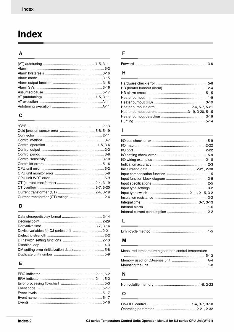
Index-2 CJ-series Temperature Control Units Operation Manual for NJ-series CPU Unit(W491)
Index
Index
A
(AT) autotuning .....................................................1-5, 3-11Alarm ............................................................................. 5-2Alarm hysteresis .......................................................... 3-16Alarm mode ................................................................. 3-15Alarm output function .................................................. 3-15Alarm SVs ................................................................... 3-16Assumed cause ........................................................... 5-17AT (autotuning) .....................................................1-5, 3-11AT execution ................................................................A-11Autotuning execution ...................................................A-11
C
C/F ............................................................................ 2-13Cold junction sensor error ....................................5-8, 5-19Connector .................................................................... 2-11Control method .............................................................. 3-7Control operation ....................................................1-5, 3-6Control output ................................................................ 2-2Control period ................................................................ 3-8Control sensitivity ........................................................ 3-10Controller errors .......................................................... 5-16CPU unit error ............................................................... 5-2CPU unit monitor error .................................................. 5-8CPU unit WDT error ...................................................... 5-9CT (current transformer) .......................................2-4, 3-19CT overflow ..........................................................5-7, 5-20Current transformer (CT) ......................................2-4, 3-19Current transformer (CT) ratings ................................... 2-4
D
Data storage/display format ......................................... 2-14Decimal point ............................................................... 2-29Derivative time ......................................................3-7, 3-14Device variables for CJ-series unit .............................. 2-21Dielectric strength .......................................................... 2-2DIP switch setting functions ........................................ 2-13Disabled loop ................................................................. 4-3DM setting error (initialization data) ............................... 5-8Duplicate unit number ................................................... 5-9
E
ERC indicator .......................................................2-11, 5-2ERH indicator .......................................................2-11, 5-2Error processing flowchart ............................................ 5-3Event code .................................................................. 5-17Event levels ................................................................. 5-17Event name ................................................................. 5-17Events ......................................................................... 5-16
F
Forward ......................................................................... 3-6
H
Hardware check error .................................................... 5-8HB (heater burnout alarm) ............................................. 2-4HB alarm errors ........................................................... 5-15Heater burnout .............................................................. 1-5Heater burnout (HB) .................................................... 3-19Heater burnout alarm ....................................2-4, 5-7, 5-21Heater burnout current ..............................3-19, 3-20, 5-15Heater burnout detection ............................................. 3-19Hunting ........................................................................ 5-14
I
I/O bus check error ........................................................ 5-9I/O map ........................................................................ 2-22I/O port ........................................................................ 2-22I/O setting check error ................................................... 5-9I/O wiring examples ..................................................... 2-18Indication accuracy ........................................................ 2-3Initialization data .................................................2-21, 2-30Input compensation function ......................................... 1-5Input function block diagram .......................................... 2-5Input specifications ........................................................ 2-5Input type settings ......................................................... 3-2Input type switch ..........................................2-11, 2-15, 3-2Insulation resistance ...................................................... 2-2Integral time ..........................................................3-7, 3-13Internal alarm ................................................................ 1-6Internal current consumption ......................................... 2-2
L
Limit-cycle method ........................................................ 1-5
M
Measured temperature higher than control temperature ................................................................................... 5-13
Memory used for CJ-series unit ....................................A-4Mounting the unit ........................................................... 1-8
N
Non-volatile memory ............................................1-6, 2-23
O
ON/OFF control .............................................1-4, 3-7, 3-10Operating parameter ..........................................2-21, 2-32

Index-3CJ-series Temperature Control Units Operation Manual for NJ-series CPU Unit(W491)
Index
I
Operation data ................................................... 2-21, 2-24Output circuits ............................................................. 2-17Output errors ............................................................... 5-14Output indicators ......................................................... 2-11Overshooting ............................................................... 5-13
P
PID constant ...................................................... 3-11, 3-13PID constants bit ......................................................... 3-11PID constants calculated flag ...................................... 3-11PID control ............................................................. 1-4, 3-7PID control with two degrees of freedom ............... 1-4, 3-7Pin 1 of the DIP switch (operation in PROGRAM mode)
.................................................................................. 2-13Pin 2 of the DIP switch (×C/×F) .................... 2-5, 2-13, 3-4Pin 3 of the DIP switch ......................................... 2-14, 3-5Pin 4 of the DIP switch (control operation for loop 1)
........................................................................... 2-14, 3-6Pin 5 of the DIP switch (control operation for loop 2)
........................................................................... 2-14, 3-6Pin 6 of the DIP switch (control method) .............. 2-14, 3-7Pin 7 of the DIP switch (initialize non-volatile memory set
values) ...................................................................... 2-14Pin 8 of the DIP switch (transfer non-volatile memory set
values) ............................................................. 2-14, 2-23Platinum resistance thermometer input setting ranges . 2-6Process value (PV) Import .......................................... A-10Proportional band ................................................ 3-7, 3-13PV (process value) ........................................................ 1-5
R
RAM ............................................................................ 2-23Restart ........................................................................ 2-22Reverse ......................................................................... 3-6RUN indicator ....................................................... 2-11, 5-2
S
(SP) set point ......................................................... 1-5, 3-9Sampling period ............................................................ 2-3Sensor error ......................................................... 5-7, 5-20Set point ................................................................. 1-5, 3-9Setting error ......................................................... 5-7, 5-19Setting error numbers .......................................... 2-29, 5-7Simple method to check the temperature sensor inputs
.................................................................................. 5-12Special I/O unit area ..................................................... A-4Special I/O unit DM area ............................................... A-4Standby sequence ...................................................... 3-16Status indicators ......................................................... 2-11Stop bit ........................................................................ 3-21Sysmac Studio .............................................................. 2-7System-defined variable ............................................. 2-21
T
Temperature control errors .......................................... 5-12
Temperature control method ......................................... 2-2Temperature control unit error ....................................... 5-2Temperature units ......................................................... 3-4Thermocouple input setting ranges ............................... 2-5
U
Undershooting ............................................................. 5-13Unit configuration .......................................................... 2-7Unit number switches ...........................................2-12, A-4Unit restart .................................................................. 2-22
W
Warmup time ................................................................. 2-3

Index-4 CJ-series Temperature Control Units Operation Manual for NJ-series CPU Unit(W491)
Index


Contact Authorized Distributor:
In the interest of product improvement, specifications are subject to change without notice.
Cat. No. W491-E1-01 0711
© OMRON Corporation 2011 All Rights Reserved.
OMRON Corporation Industrial Automation Company
OMRON ELECTRONICS LLCOne Commerce Drive Schaumburg,IL 60173-5302 U.S.A.Tel: (1) 847-843-7900/Fax: (1) 847-843-7787
Regional HeadquartersOMRON EUROPE B.V.Wegalaan 67-69-2132 JD HoofddorpThe NetherlandsTel: (31)2356-81-300/Fax: (31)2356-81-388
Contact: www.ia.omron.comTokyo, JAPAN
OMRON ASIA PACIFIC PTE. LTD.No. 438A Alexandra Road # 05-05/08 (Lobby 2), Alexandra Technopark, Singapore 119967Tel: (65) 6835-3011/Fax: (65) 6835-2711
OMRON (CHINA) CO., LTD.Room 2211, Bank of China Tower, 200 Yin Cheng Zhong Road, PuDong New Area, Shanghai, 200120, ChinaTel: (86) 21-5037-2222/Fax: (86) 21-5037-2200