temperature controller dvs-21ha -...
TRANSCRIPT

User's Guide
Read this guide carefully before using the controller.
DVS-21HATemperature Controller
SET

2 DVS-21HA.rev.03
TABLE OF CONTENTS
PRECAUTIONS .............................................................. 3FEATURES ..................................................................... 4LOCATION OF THE CONTROLS................................... 6
Controller Status Leds ................................................... 6Internal Switches ........................................................... 7
INSTALLATION .............................................................. 8Mounting Instructions ..................................................... 8Connections .................................................................. 8Motor Types .................................................................. 9Heating/Cooling Option ................................................. 10Temperature Probes ..................................................... 11
CHANGING THE PARAMETER SETTINGS .................. 14Using the Display .......................................................... 14Locking the Parameters Settings .................................. 15
TEMPERATURE SETTINGS .......................................... 16Temperature Units ........................................................ 16Viewing Temperatures .................................................. 16Temperature Set Point .................................................. 19Temperature Curve ....................................................... 20
VENTILATION SETTINGS.............................................. 24Cooling Operation ......................................................... 24Minimum Ventilation Cycle ............................................ 26Using Stage 2 Fans for Minimum Ventilation ................. 28Humidity Compensation ................................................ 30Minimum Speed Curve.................................................. 32Outside Temp. Compensation on Stage 1 Bandwidth ... 39Ventilation Settings ....................................................... 40Merging Stage 1 and 2 Fans ......................................... 44Mist Cooling .................................................................. 45
HEATER SETTINGS....................................................... 48Humidity Compensation ................................................ 50
ALARM SETTINGS ......................................................... 53TROUBLESHOOTING GUIDE........................................ 55TECHNICAL SPECIFICATIONS .................................... 60FACTORY SETTINGS .................................................... 61FUNCTION SUMMARY .................................................. 63
Page

3DVS-21HA.rev.03
We strongly recommend installing supplementary naturalventilation as well as a back-up thermostat on at least onecooling stage (refer to the wiring diagram enclosed with thisuser's manual to connect the thermostat).
Although fuses at the input and outputs of the controller protectits circuits in case of an overload or overvoltage, werecommend installing an additional protection device on thecontroller's supply circuit.
The room temperature where the controller is located MUSTALWAYS REMAIN BETWEEN 32°F AND 104°F (0°C TO 40°C).
To avoid exposing the controller to harmful gases or exces-sive humidity, it is preferable to install it in a corridor.
DO NOT SPRAY WATER ON THE CONTROLLER
PRECAUTIONS
FOR CUSTOMER USEEnter the serial number located onthe side of the controller below forfuture reference.
Model number:Serial number:
DVS-21HA

4 DVS-21HA.rev.03
The DVS-21HA is an electronic device used for environmental control inlivestock buildings. It allows the user to maintain a specified target tem-perature by controlling the operation of ventilation and heating equipment.Two stages of variable speed fans can be connected to the controller, aswell as one stage of either constant-speed fans or heating units. In addition,the constant-speed fan stage can be configured as a mist cooling stage.
The main features of the DVS-21HA are as follows:
THREE-DIGIT DISPLAY : A three-digit display provides a high level of accu-racy, allowing the user to specify a temperature to within one tenth of adegree (in Fahrenheit or Celsius units).
PILOT LIGHTS : Pilot lights indicating the state of outputs allow the user tomonitor the operation of the system without having to enter the building.
MINIMUM VENTILATION CYCLE : When ventilation is not required for cool-ing, the first and second stage fans can be operated either continuously orintermittently to reduce the level of humidity and supply oxygen to the room.
TEMPERATURE AND MINIMUM VENTILATION SPEED CURVES : Thecontroller can be set to automatically change the temperature set point andthe minimum ventilation speed over a given period of time in accordancewith the user's requirements by specifying a temperature curve and a mini-mum ventilation speed curve with up to six different points each.
CHOICE OF TEN MOTOR TYPES: The variation in motor speed resultingfrom a change in voltage will depend on the make and capacity of the motor.In order to achieve a high degree of compatibility between controller andmotor, the user can choose from among ten different motor types, thusensuring that the correct voltage is supplied.
MERGING OF STAGE 1 AND 2 FANS : Merging can be applied to smooththe transition between the operation of Stage 1 and 2 fans.
HIGH/LOW TEMPERATURE ALARM OUTPUT
HUMIDITY COMPENSATION: The stage 1 minimum speed can be ad-justed automatically as a function of relative humidity. As humidity increases,the minimum speed of stage 1 fans increases proportionally to compensatefor the change. An alternative method uses Heater 1 to compensate for highhumidity levels.
FEATURES

5DVS-21HA.rev.03
DVS-21HA
FULL-SPEED FAN START-UP : In order to overcome the inertia of theventilation system components and de-ice the fan blades in cold weatherconditions, the controller supplies maximum voltage to the variable speedfans during the 2 seconds immediately following each start-up.
OUTSIDE TEMPERATURE COMPENSATION OF STAGE 1 BAND-WIDTH: If an INTERFACE-3 is connected to the DVS-21HA, a compen-sation is applied to the Stage 1 bandwidth in cold weather conditions toallow for momentary increases in room temperature.
FOUR INDEPENDENT TEMPERATURE PROBE INPUTS : Up to fourtemperature probes can be connected to the controller in order to obtaina more accurate reading of the average room temperature and a fasterreaction time.
OVERLOAD AND OVERVOLTAGE PROTECTION : Fuses are installedat the input and outputs of the controller to protect its circuitry in the caseof an overload or overvoltage.
COMPUTER CONTROL: The controller can be connected to a com-puter, thus making it possible to centralize the management of informa-tion and diversify control strategies.
CONTROL OF AIR INLET MOVEMENT : If the DVS-21HA is used incombination with a WR-F-1AB controller, the movement of the air inletscan be coordinated with the operation of the fans using a potentiometerlocated on the panel drive. This allows the air inlets to be adjusted cor-rectly, without the influence of uncontrollable factors such as wind or airfrom adjoining rooms.
TEST MODE: A test mode allows you to simulate temperature changesand verify controller performance.

6 DVS-21HA.rev.03
LOCATION OF THE CONTROLS
CONTROLLER STATUS LEDS
DEL GNINAEM
1EGATS .NOERASNAF1EGATSNEHWNOSNRUT
2EGATS .NOERASNAF2EGATSNEHWNOSNRUT
/3EGATS1RETAEH .NOERASTINUGNITAEHROSNAF3EGATSNEHWNOSNRUT
.PS.NIM/.PMETEVRUC
SNRUT.DETAVITCASIEVRUCERUTAREPMETEHTNEHWSEHSALF.NOOSLASIEVRUCDEEPSNOITALITNEVMUMINIMEHTNEHWNO
EBORP.FED DETCETEDSIEBORPEVITCEFEDANEHWNOSNRUT
MRALA .DETCETEDSIMRALANANEHWNOSNRUT
DEKCOL .DEKCOLERASRETEMARAPEHTNEHWNOSNRUT
YTIDIMUHNOITASNEPMOC
SI2-1EGATSNODEEPSMUMINIMEHTNEHWNOSNRUTOTDESUGNIEBSI1RETAEHNEHW,DETASNEPMOC
NONOITASNEPMOCEHTNEHWROYTIDIMUHROFETASNEPMOC.TCEFFENISIEGATSTSIMEHT
SET
Adjustment Knob
Function Selector
Button
Digital Display

7DVS-21HA.rev.03
DVS-21HA
# FFO NO
1 SRETEMARAPDEKCOLNU SRETEMARAPDEKCOL
2 SEERGEDTIEHNERHAF SEERGEDSUISLEC
3 DELBASID2EBORP DELBANE2EBORP
4 DELBASID3EBORP DELBANE3EBORP
5 DELBASID4EBORP DELBANE4EBORP
6 EGATSGNITAEHON GNITAEH
7 FFOTSIM NOTSIM
8 2-1SEGATSEGREMTONOD 2-1SEGATSEGREM
9NOITASNEPMOCYTIDIMUHDEEPS.NIM2-1EGATSNO
NOITASNEPMOCYTIDIMUH1RETAEHGNISU
01 DEVRESER
11 DEVRESER
21 DEVRESER
INTERNAL SWITCHES
The internal switches are located on the inside of the front cover. When thecontroller is shipped from the factory, all the switches are set to OFF.
ON
21 3 4 6 75 8 9 1110 12

8 DVS-21HA.rev.03
To connect the controller, refer to the wiring diagram enclosed with this user'smanual.
n Set the voltage switch to the appropriate voltage.
n Use the electrical knockouts provided at the bottom of the enclosure.Do not make additional holes in the enclosure, particularly on the sideof the enclosure when using a computer communications module.
n If metallic cable holders are used to secure cables entering theenclosure, use the ground plate provided with the controller. Connectthe ground wire to the ground stud on the plate.
n If Stage 3 is used for heating, it may be necessary to install atransformer in order to supply the appropriate voltage to the heating unit.
ALARM CONNECTION: There are two types of alarms on the market. Onetype activates when current is cut off at its input, whereas the other activateswhen current is supplied at its input. For an alarm of the first type, use the NOterminal as shown on the wiring diagram. For an alarm of the second type, usethe NC terminal.
ALL WIRING MUST BE DONE BY AN AUTHORIZED ELECTRICIANAND MUST COMPLY WITH APPLICABLE CODES, LAWS ANDREGULATIONS. BE SURE POWER IS OFF BEFORE DOING ANYWIRING TO AVOID ELECTRICAL SHOCKS AND EQUIPMENT DAM-AGE.
INSTALLATION
MOUNTING INSTRUCTIONS
CONNECTIONS
!WARNING
Open the latch and lift the cover. Remove the black caps located on each ofthe four mounting holes. Mount the enclosure to the wall using four screws.Insert the screws into the mounting holes and tighten. Fasten the blackcaps onto the mounting holes.

9DVS-21HA.rev.03
DVS-21HA
The relationship between the voltage supplied to a motor and its operatingspeed is described by a motor curve. This curve varies with the make andcapacity of the motor. The various motors available in the industry have beendivided into ten categories and the controller has been programmed with adifferent motor curve for each of these categories. To ensure that thecontroller supplies the correct voltages, an appropriate curve must beselected for Stage 1 and Stage 2 according to the type of fan motors used.
1 Selecting a Motor Type for Stage 1
Refer to the list of motors enclosed with this user's manual to determine whichtype number (1 to 10) is appropriate for the motors used.
n Set the selection knob toSTAGE 1 — BANDWIDTH/TIMER. The Stage 1 bandwidth isdisplayed and flashes.
n Press the push-button three times.The currently selected motor typeis displayed, alternating with theletters "tYP".
n Use the adjustment knob to adjust the motor type to the desired value.
n Return to the Stage 1 bandwidth display by pressing the push-buttononce again.
2 Selecting A Motor Type for Stage 2
Refer to the list of motors enclosed with this user's manual to determine whichtype (1 to 10) is appropriate for the motors used.
MOTOR TYPES

10 DVS-21HA.rev.03
DVS-21HA
HEATING / COOLING OPTION
n Set the selection knob to STAGE 2 — OFFSET/BANDWIDTH .The offset is displayed, alternating with the letters "OFT".
n Press the push-button twice. The currently selected motor typeflashes.
n Use the adjustment knob to adjust the motor type to the desiredvalue.
n Return to the Stage 2 offset display by pressing the push-buttononce again.
Stage 3 can operate as a heating or cooling stage.
ð Set switches # 6 to OFF to use stage3 for cooling.
ð Set switch # 6 to ON to use Stage 3for heating.
6
ON

11DVS-21HA.rev.03
DVS-21HA
1 Connecting the Probes
The controller is supplied with one temperature probe connected to input# 1. Up to three additional probes can be connected to the controller in orderto obtain a more accurate reading of the average room temperature and afaster reaction time.
n Use inputs # 2, 3 and 4 to connect additional probes, as shown on thewiring diagram enclosed.
CAUTION: Probes operate at low voltage and are isolated from the supply.Be sure that probe cables remain isolated from all high voltage sources. Inparticular, do not route the probe cables through the same electrical knockoutas other cables. Do not connect the shield from the probe cable to a terminalor a ground.
Switches are used to activate or deactivate the additional probes connectedto the controller.
n Activate each additional probe by settingthe appropriate switch to ON:
• Switch # 3 activates the probe connected to input # 2.• Switch # 4 activates the probe connected to input # 3.• Switch # 5 activates the probe connected to input # 4.
TEMPERATURE PROBES
3 4 5
ON
12 DVS-21HA.rev.03
DVS-21HA
2 Extending the Probes
Each probe can be extended up to 500 feet (150 meters). To extend a probe:
n Use a shielded cable of outside diameter between 0.245 and 0.260 in(6.22 and 6.60 mm) (the cable dimensions should not be under 18AWG) to ensure the cable entry is liquid tight. Do not ground theshielding.
n It is preferable to solder the cable joint to ensure a proper contactbetween the two cables.
CAUTION: Do not run probe cables next to other power cables. Whencrossing over other cables, cross at 90°.
3 Defective Probes
If a defective probe is detected, the Defective Probe Pilot Light turns on. Theroom temperature shown on the display is then the average temperaturemeasured by the probes in working condition. The controller will operateaccording to this temperature.To identify the defective probe:
n Set the selection knob to ROOMTEMPERATURE . The room tem-perature is displayed.
n Press the push-button. If the probe connected to input # 1 and sup-plied with the controller is not defective, the letters"PR1" are dis-played, alternating with the on/off state of the probe and the tempera-ture measured by the probe. If the probe is defective, the letters"PR1" are displayed, alternating with the state of the probe and theletter "P".
For each additional probe connected to the controller:
13DVS-21HA.rev.03
DVS-21HA
n Press the push-button once again. If the probe is not defective, theletters "PR#" (where # is the number of the input to which the probe isconnected) are displayed, alternating with the on/off state of the probeand the temperature measured by the probe. If the probe is defective,the letters "PR#" are displayed, alternating with the on/off state of theprobe and the letter "P".

14 DVS-21HA.rev.03
Flashing V alues: The dis-play will flash in certain casesand not in others. The flash-ing indicates that the valueshown can be adjusted. Avalue that is not flashing can-not be adjusted.
CHANGING THE PARAMETER SETTINGS
USING THE DISPLAY
Relative and Absolute Values: Some parameter adjustments are displayedboth as a relative value and an absolute temperature. This applies to all heatingand cooling differentials, the mist differential and the heater offset. Theparameter is first displayed as a relative value. The corresponding absolutetemperature is displayed after six seconds if no action is taken by the user.The absolute value is the temperature at which the stage turns on (except inthe case of the heater and mist offsets where the value displayed is thetemperature at which the stage turns off). If the user turns the adjustmentknob, the relative value reappears. For example, when the user turns theselection knob to a differential position, i.e. STAGE 3—DIFFERENTIAL, thesequence is as follows:
(i) The current differential for stage 3 flashes on the display, alternating with"St. 3".
78.0
(ii) If, after about 6 seconds, no action is taken by the user, the absolutetemperature value is displayed, alternating with "St. 3". In this case, theabsolute value is: Set Point + Bandwidth 1 + Offset 2 + Bandwidth 2 +Differential 3.
St. 32.0
15DVS-21HA.rev.03
DVS-21HA
The parameter settings can be locked to prevent accidentally modifyingthem. When the settings are locked, only the temperature set point and theStage 1 minimum ventilation speed can be modified (as long as the tem-perature curve and the minimum ventilation speed curve are deactivatedrespectively).
To lock the parameter settings:
n Set internal switch # 1 to ON. The Locked Parameter Pilot Light turnson.
To unlock the parameter settings:
n Set internal switch # 1 to OFF. The Locked Parameter Pilot Lightturns off.
LOCKING THE PARAMETER SETTINGS
2.3
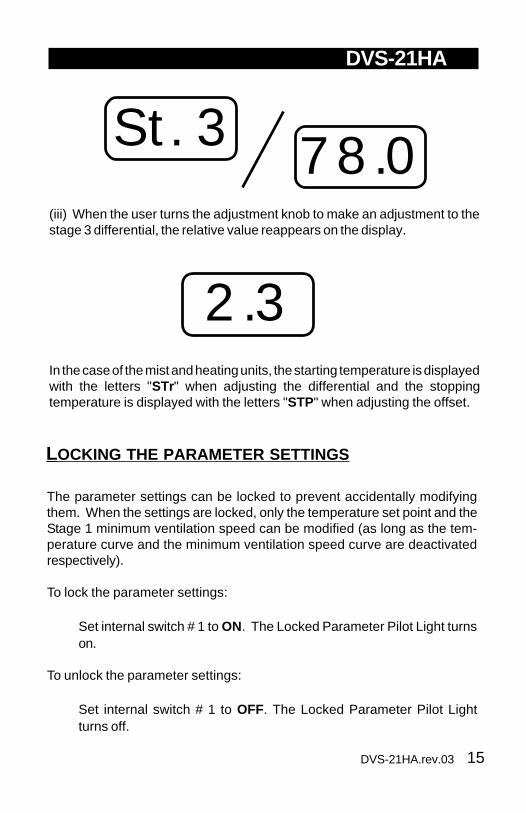
(iii) When the user turns the adjustment knob to make an adjustment to thestage 3 differential, the relative value reappears on the display.
In the case of the mist and heating units, the starting temperature is displayedwith the letters "STr" when adjusting the differential and the stoppingtemperature is displayed with the letters "STP" when adjusting the offset.
St. 378.0

16 DVS-21HA.rev.03
Temperatures can be displayed in either Celsius orFahrenheit units
n Set internal switch # 2 to the desired position:
• ON to display temperatures in Celsius units.• OFF to display temperatures in Fahrenheit units.
TEMPERATURE SETTINGS
To display the desired temperature,set the selection knob to ROOMTEMPERATURE. The readout candisplay values from -40.0oF to 120.0oF( -40.0oC to 48.9oC).
1 Viewing Room Temperature
The room temperature is the average value of all temperatures measured byactivated probes in proper operating condition.
n Set the selection knob to ROOM TEMPERATURE. The room tem-perature is displayed.
2 Viewing Probe Temperatures
The controller can display probe temperatures individually. Probes can alsobe turned on or off to control the temperature in different parts of the building.
n Set selection knob to ROOM TEMPERATURE. The average roomtemperature is displayed.
TEMPERATURE UNITS
VIEWING TEMPERATURES
ON
2

17DVS-21HA.rev.03
DVS-21HA
n Press the push-button. The temperature reading from probe 1 is dis-played, alternating with the letters "Pr 1" and the on/off state of probe1.
n For each additional probe, press the push-button. The temperaturereading from probe x is displayed, alternating with the letters "Pr x "and the on/off state of the probe, etc.
Note: The display returns to the average room temperature after oneminute.
3 Viewing Minimum / Maximum Temperatures
The minimum and maximum temperatures are the lowest and highest tem-perature values recorded since the last reset. Maximum and minimumtemperature values are recorded for the average room temperature as wellas for individual probe temperatures.
n Set the selection knob to ROOM TEMPERATURE. The room tem-perature is displayed.
n Turn the adjustment knob clockwise by one notch. The minimumtemperature is displayed, alternating with the letters "Lo ".
n Turn the adjustment knob clockwise one notch further. The maximumtemperature is displayed, alternating with the letters "Hi".
n Turn the adjustment knob clockwise a third notch. The room tempera-ture is displayed again.
n For each individual probe, press the push-button. The temperaturereading from probe x is displayed, alternating with the letters "Pr x "and the on/off state of the probe.
n Turn the adjustment knob clockwise by one notch. The minimumtemperature is displayed, alternating with the letters "Lo ".
18 DVS-21HA.rev.03
DVS-21HA
n Turn the adjustment knob clockwise one notch further. The maximumtemperature is displayed, alternating with the letters "Hi".
n Turn the adjustment knob clockwise a third notch. The probe tem-perature is displayed again.
n Press the push-button to access the other probes, etc.
NOTE: If you let the display flash for more than 10 seconds, the controllerresets the minimum and maximum temperatures currently in memory (thedisplay stops flashing to indicate that the reset has been done).

19DVS-21HA.rev.03
DVS-21HA
TEMPERATURE SET POINT
The temperature set point is the tar-get room temperature. It can be ad-justed between -40.0°F and 99.9°F(-40.0°C and 37.7°C).
Adjusting Temperature Set Point
n Set the selection knob to SET POINT / To CURVE.The current setpoint flashes on the display.
n Use the adjustment knob to adjust the set point to the desired value.
NOTE: The temperature set point can be adjusted only if the temperaturecurve is deactivated (see following section).

20 DVS-21HA.rev.03
DVS-21HA
The user can define a temperature curve to adjust the set point automaticallyover a given time period.
TEMPERATURE CURVE
Temperature
Days
To1T o2T o3To4To5To6
d4 d25 d35 d50 d70 d80
○
○
○
○
○
○
○
○
○
○
○
○
○
○
○
○
○
○
○
○
○
○
○
○
○
○
○
○
○
○
○
○
○
○
○
○
○
○
○
○
○
○
A curve is defined using six points. Each point specifies a day number anda set point for that day. Once the points of the curve are defined, the curvemust be activated. The controller will change the temperature set point everyhour in a linear fashion between consecutive points of the curve. When thelast point of the curve is reached, the temperature set point for that day ismaintained until the curve is reactivated.
NOTES:
i) All six points of the curve must be specified. If six points are not needed,repeat the last temperature value for each unnecessary point.
ii) Certain restrictions apply to reduce the risk of errors:
− The highest possible day number is 99.
− Decreasing day numbers are not allowed.
− Increasing temperatures are not allowed.
− The temperature variation cannot exceed 3°F (1.6°C) per day.

21DVS-21HA.rev.03
DVS-21HA
1 Specifying the Curve
n Set the selection knob to SETPOINT / To CURVE. The cur-rent temperature set pointflashes on the display.
n Press the push-button. The word OFF is displayed indicating that thetermperature curve is deactivated. If this is not the case, see belowto deactivate the curve.
Repeat the following steps for each of the six points:
n Press the push-button once again. The day number is displayed,alternating with the word "day ".
n Using the adjustment knob, set the day number to the desired value.
n Press the push-button once again. The current temperature set pointis displayed, alternating with the word "set ".
n Using the adjustment knob, adjust the set point to the desired value.
Once the six points of the curve have been specified, activate the curve asexplained below.
NOTE: Make sure the temperature curve is deactivated before specifyingnew points (see below).

22 DVS-21HA.rev.03
DVS-21HA
2 Activating Temperature Curve
If you have just finished specifying the points on the curve:
n Press the push-button once again. The word OFF flashes on thedisplay.
n Turn the adjustment knob clockwise one notch. The word ON flasheson the display and the Temperature Curve Pilot Light flashes, indi-cating that the temperature curve is now activated.
n Set the selection knob to ROOM TEMPERATURE.
If you have previously defined the points on the curve:
n Set the selection knob to SET POINT / To CURVE. The currentvalue of the temperature set point flashes on the display.
n Press the push-button. The word OFF is displayed.
n Press the push-button to display the points of the curve currentlydefined until the word OFF appears (thirteen clicks).
n Turn the adjustment knob clockwise one notch. The word ON flasheson the display and the Temperature Curve Pilot Light flashes, indi-cating that the temperature curve is now activated.
n Set the selection knob to ROOM TEMPERATURE.
23DVS-21HA.rev.03
DVS-21HA
3 Viewing Current Set Point and Day Number
When the temperature curve is activated, the current temperature setpoint and day number can be viewed at any time. The current day num-ber can also be adjusted in order to move forward or backward on thetemperature curve.
n Set the selection knob to SET POINT / To CURVE. The currenttemperature set point is displayed.
n Press the push-button. The current day number is displayed,alternating with the letters "cur. day ".
n Use the adjustment knob to set the day number to the de-sired value.
4 Deactivating Temperature Curve
n Set the selection knob to SET POINT / To CURVE. The currenttemperature set point is displayed.
n Press the push-button to display the points of the curve actuallydefined until the word ON appears (fourteen clicks).
n Turn the adjustment knob counterclockwise one notch. The wordOFF flashes on the display and the Temperature Curve Pilot Lightturns off indicating that the temperature curve is now deactivated.
n Set the selection knob to ROOM TEMPERATURE.

24 DVS-21HA.rev.03
• When room temperature < Set Point, stage 1 fans run at minimumspeed according to the minimum ventilation cycle. If minimum ventilationhas been activated for stage 2, stage 2 fans also provide minimumventilation.
• At Set Point: stage 1 fans stop operating according to the minimumventilation cycle and increase in speed as the room temperature rises.
• At Set Point + Bandwidth 1: stage 1 fans reach full speed.
• At Set Point + Bandwidth 1 + Stage 2 Offset: stage 2 fans start runningcontinuously.
If room temperature rises:
The DVS-21HA controls two stages of variable-speed fans (Stage 1 - 2) andone optional stage of constant-speed fans (Stage 3).
VENTILATION SETTINGS
COOLING OPERATION
RoomTemp.
TemperatureSet Point
STAGE 1
STAGE 2
STAGE 3
BandwidthStage 1
MinimumVentilation
CycleBandwidthStage 2
Stage 2Offset
DifferentialStage 3
Figure 1: Cooling Operation

25DVS-21HA.rev.03
DVS-21HA
• At Set Point + Bandwidth 1 + Stage 2 Offset + Bandwidth 2: stage 2 fansreach full speed.
• At Set Point + Bandwidth 1 + Stage 2 Offset + Bandwidth 2 + Diff. 3:stage 3 fans start running.
If the room temperature falls:
• At Set Point + Bandwidth 1 + Stage 2 Offset + Bandwidth 2: stage 3fans return to a stop; stage 2 fans start decreasing in speed as thetemperature decreases.
• At Set Point + Bandwidth 1 + Stage 2 Offset: if minimum ventilationhas been activated for stage 2, stage 2 fans run according to the mini-mum ventilation cycle; otherwise, stage 2 fans return to a stop.
• At Set Point + Bandwidth 1: Stage 1 fans start decreasing in speed asthe temperature decreases.
• At Set Point: Stage 1 fans reach minimum speed.
• Below the Set Point: stage 1 fans stop operating continuously andoperate according to the minimum ventilation cycle at minimum speed.If minimum ventilation has been activated for stage 2, stage 2 fansalso provide minimum ventilation.
26 DVS-21HA.rev.03
DVS-21HA
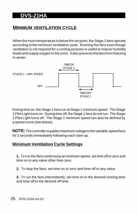
When the room temperature is below the set point, the Stage 1 fans operateaccording to the minimum ventilation cycle. Running the fans even thoughventilation is not required for a cooling purpose is useful to reduce humiditylevels and supply oxygen to the room. It also prevents the fans from freezingin winter.
During time on, the Stage 1 fans run at Stage 1 minimum speed. The Stage1 Pilot Light turns on. During time off, the Stage 1 fans do not run. The Stage1 Pilot Light turns off. The Stage 1 minimum speed can also be defined bya speed curve (see below).
NOTE: The controller supplies maximum voltage to the variable-speed fansfor 2 seconds immediately following each start-up.
Minimum Ventilation Cycle Settings
1. To run the fans continously at minimum speed, set time off to zero andtime on to any value other than zero.
2. To stop the fans, set time on to zero and time off to any value.
3. To run the fans intermittently, set time on to the desired running timeand time off to the desired off time.
MINIMUM VENTILATION CYCLE
STAGE 1 — MIN. SPEED
OFF
TIME ONSTAGE 1
TIME OFFSTAGE 1
27DVS-21HA.rev.03
DVS-21HA
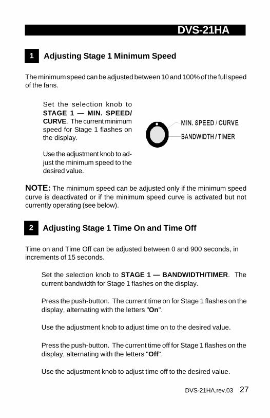
1 Adjusting Stage 1 Minimum Speed
The minimum speed can be adjusted between 10 and 100% of the full speedof the fans.
n Set the selection knob toSTAGE 1 — MIN. SPEED/CURVE. The current minimumspeed for Stage 1 flashes onthe display.
n Use the adjustment knob to ad-just the minimum speed to thedesired value.
NOTE: The minimum speed can be adjusted only if the minimum speedcurve is deactivated or if the minimum speed curve is activated but notcurrently operating (see below).
2 Adjusting Stage 1 Time On and Time Off
Time on and Time Off can be adjusted between 0 and 900 seconds, inincrements of 15 seconds.
n Set the selection knob to STAGE 1 — BANDWIDTH/TIMER . Thecurrent bandwidth for Stage 1 flashes on the display.
n Press the push-button. The current time on for Stage 1 flashes on thedisplay, alternating with the letters "On".
n Use the adjustment knob to adjust time on to the desired value.
n Press the push-button. The current time off for Stage 1 flashes on thedisplay, alternating with the letters "Off ".
n Use the adjustment knob to adjust time off to the desired value.

28 DVS-21HA.rev.03
DVS-21HA
USING STAGE 2 FANS FOR MINIMUM VENTILATION
Stage 2 fans can provide minimum ventilation whenever they are notneeded for cooling purposes, i.e. when the room temperature is less thanSet Point + Stage 1 Bandwidth + Stage 2 Offset. In this case, Stage 2fans operate according to their own minimum ventilation cycle. Thisfeature is activated by setting the Stage 2 Time On value to a value otherthan zero. Figure 2 below sums up the operation of stage 1 and 2 fans:
RoomTemp.
TemperatureSet Point
STAGE 1FULL
STAGE 2MINIMUM
BandwidthStage 1
BandwidthStage 2
OffsetStage 2
STAGE 1MINIMUM
STAGE 2FULL
Figure 2: Stage 1 and 2 Operation showing Minimum Ventilation

29DVS-21HA.rev.03
DVS-21HA
Adjusting Stage 2 Time On and Time Off
To activate minimum ventilation for Stage 2 fans, set Time On to a valueother than zero. Time on and Time Off can be adjusted between 0 and 900seconds, in increments of 15 seconds.
n Set the selection knob to STAGE 2— MIN. SPEED. The currentminimum speed for Stage 2 flashes on the display.
n Press the push-button. The current time on for Stage 2 flashes on thedisplay, alternating with the letters "On".
n Use the adjustment knob to adjust time on to the desired value.
n Press the push-button. The current time off for Stage 2 flashes on thedisplay, alternating with the letters "Off ".
n Use the adjustment knob to adjust time off to the desired value.
30 DVS-21HA.rev.03
DVS-21HA
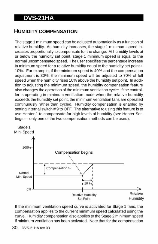
HUMIDITY COMPENSATION
The stage 1 minimum speed can be adjusted automatically as a function ofrelative humidity. As humidity increases, the stage 1 minimum speed in-creases proportionally to compensate for the change. At humidity levels ator below the humidity set point, stage 1 minimum speed is equal to thenormal uncompensated speed. The user specifies the percentage increasein minimum speed for a relative humidity equal to the humidity set point +10%. For example, if the minimum speed is 40% and the compensationadjustment is 30%, the minimum speed will be adjusted to 70% of fullspeed when the humidity rises 10% above the humidity set point. In addi-tion to adjusting the minimum speed, the humidity compensation featurealso changes the operation of the minimum ventilation cycle: if the control-ler is operating in minimum ventilation mode when the relative humidityexceeds the humidity set point, the minimum ventilation fans are operatedcontinuously rather than cycled. Humidity compensation is enabled bysetting internal switch # 9 to OFF. The alternative to using this feature is touse Heater 1 to compensate for high levels of humidity (see Heater Set-tings — only one of the two compensation methods can be used).
If the minimum ventilation speed curve is activated for Stage 1 fans, thecompensation applies to the current minimum speed calculated using thecurve. Humidity compensation also applies to the Stage 2 minimum speedif minimum ventilation has been activated. Note that for the compensation
RelativeHumidity
Relative HumiditySet Point
Stage 1Min. Speed
Compensation begins
0%
100%
NormalMin. Speed
Compensation %
10 %
31DVS-21HA.rev.03
DVS-21HA
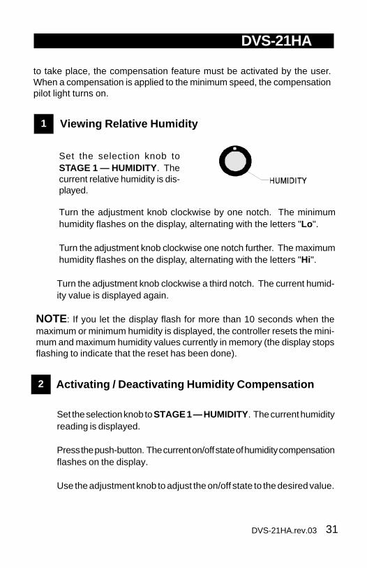
1 Viewing Relative Humidity
n Set the selection knob toSTAGE 1 — HUMIDITY. Thecurrent relative humidity is dis-played.
n Turn the adjustment knob clockwise by one notch. The minimumhumidity flashes on the display, alternating with the letters "Lo ".
n Turn the adjustment knob clockwise one notch further. The maximumhumidity flashes on the display, alternating with the letters "Hi".
n Turn the adjustment knob clockwise a third notch. The current humid-ity value is displayed again.
NOTE: If you let the display flash for more than 10 seconds when themaximum or minimum humidity is displayed, the controller resets the mini-mum and maximum humidity values currently in memory (the display stopsflashing to indicate that the reset has been done).
2 Activating / Deactivating Humidity Compensation
n Set the selection knob to STAGE 1 — HUMIDITY. The current humidityreading is displayed.
n Press the push-button. The current on/off state of humidity compensationflashes on the display.
n Use the adjustment knob to adjust the on/off state to the desired value.
to take place, the compensation feature must be activated by the user.When a compensation is applied to the minimum speed, the compensationpilot light turns on.

32 DVS-21HA.rev.03
DVS-21HA
3 Adjusting Relative Humidity Set Point
When the relative humidity exceeds the humidity set point, stage 1 mini-mum speed is increased by a proportional amount to compensate for theincrease in humidity (if minimum ventilation is activated on stage 2, stage 2minimum speed is also compensated). Note that the humidity compensa-tion feature must be activated for this to work.
n Set the selection knob to STAGE 1 — HUMIDITY. The current humidityreading is displayed.
n Press the push-button twice. The relative humidity set point isdisplayed, alternating with the letters "set rH ".
n Use the adjustment knob to adjust the set point to the desired value.
4 Adjusting Minimum Speed Compensation
This is the percentage increase in minimum speed for a relative humidityequal to the humidity set point + 10%. The value ranges from 0 to 100%.
n Set the selection knob to STAGE 1 — HUMIDITY . The current humidityreading is displayed.
n Press the push-button three times. The current minimum speedcompensation is displayed, alternating with the letters "SPd".
n Use the adjustment knob to adjust the minimum speed compensationto the desired value.

33DVS-21HA.rev.03
DVS-21HA
NOTE:
If the room temperature falls below the values shown in Table 1 below, thefans will begin to run at the minimum speed specified for the first point ofthe curve and will continue to do so as long as the room temperatureremains below the set point. When the room temperature rises above theset point, the fans will return to the current minimum speed, calculatedaccording to the minimum speed curve.
Temperatureor Speed
Daysd4 d25 d35 d50 d70 d80
○
○
○
○
○
○
○
○
○
○
○
○
○
○
○
○
○
○
○
○
○
○
○
○
○
○
○
○
○
○
○
○
○
○
○
○
○
○
○
○
○
○
○
○
○
○
d10
Minimum Speed Curve
Temperature Curve
The user can define a minimum ventilation speed curve to adjust theStage 1 minimum speed automatically over a given time period. Eachcurve is defined by six points. Each point specifies a day number and afan speed for that day. Once the points are defined, the minimum speedcurve must be activated. When the minimum speed curve is activated,the controller adjusts the Stage 1 minimum speed every hour in a lin-ear fashion between two consecutive points.
When the last point of the curve is reached, the curve is deactivated. Thecontroller maintains the minimum speed specified for this point until thecurve is reactivated or until a new single minimum speed is specifiedusing the first method.
MINIMUM VENTILATION SPEED CURVE

34 DVS-21HA.rev.03
DVS-21HA
Interaction Between T emperature and Minimum S peedCurves
• The minimum speed curve can be activated only if the temperaturecurve is already activated
• All points of the minimum speed curve other than the first one areautomatically given day numbers identical to those specified for the tem-perature curve. Only the first point of the minimum speed curve has anadjustable day number. This day number must be greater or equal to theday number specified for the first point of the temperature curve and lessthan the day number specified for the second point of the temperature curve(see example 1).
TEMPERATURE CURVE
POINT 1
POINT 2
MINIMUM SPEED CURVE
d5
d20
d5 to d19 (adjustable)
d20 (not ajustable)
EXAMPLE 1
Table 1.
''Set Point - 5.0°F (2.8°C) - Heater Offset - Stage 3 Differential''
OR
''Set Point'', if the parameter settings are such that the pre-ceding value is greater than the set point.
STAGE 3OPERATION THRESHOLD VALUE
Cooling ''Set Point - 5.0°F (2.8°C)''
Heating

35DVS-21HA.rev.03
DVS-21HA
• If you activated the temperature curve yesterday, the current day num-ber of the temperature curve is d6. Therefore, if you activate the minimumspeed curve today, it will effectively be in operation in 4 days, when thecurrent day number of the temperature curve reaches d10. In the mean-time, the fans will run at the specified single minimum speed (seeexample 2).
• If you activated the temperature curve six days ago, the current daynumber of the temperature curve is d11. Therefore, if you activate the mini-mum speed curve today, it will effectively be in operation the moment youactivate it. In this case, the current minimum speed will be a value between10% and 20%.
POINT 1
POINT 2
d5
d20
TEMPERATURE CURVE MINIMUM SPEED CURVE
TemperatureDay
90.0 °F
85.0 °F
SpeedDay
d10
d20
10 %
20 %
EXAMPLE 2
• When the minimum speed curve is activated, it will effectively be oper-ating (i.e. the controller will begin to adjust the minimum speed according tothe specified points of the curve) only when the current day number of thetemperature curve reaches the first day number of the minimum speed curve.
36 DVS-21HA.rev.03
DVS-21HA
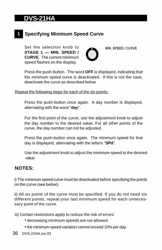
1 Specifying Minimum Speed Curve
n Set the selection knob toSTAGE 1 — MIN. SPEED /CURVE. The current minimumspeed flashes on the display.
n Press the push-button. The word OFF is displayed, indicating thatthe minimum speed curve is deactivated. If this is not the case,deactivate the curve as described below.
Repeat the following steps for each of the six points:
n Press the push-button once again. A day number is displayed,alternating with the word "day ".
n For the first point of the curve, use the adjustment knob to adjustthe day number to the desired value. For all other points of thecurve, the day number can not be adjusted.
n Press the push-button once again. The minimum speed for thatday is displayed, alternating with the letters "SPd".
n Use the adjustment knob to adjust the minimum speed to the desiredvalue.
NOTES:
i) The minimum speed curve must be deactivated before specifying the pointson the curve (see below).
ii) All six points of the curve must be specified. If you do not need sixdifferent points, repeat your last minimum speed for each unneces-sary point of the curve.
iii) Certain restrictions apply to reduce the risk of errors:• decreasing minimum speeds are not allowed.
• the minimum speed variation cannot exceed 10% per day.
37DVS-21HA.rev.03
DVS-21HA
2 Activating Minimum Speed Curve
If you have just finished specifying the points on the curve:
n Press the push-button once again. The word OFF flashes.
n Turn the adjustment knob clockwise by one notch. The word ONflashes on the display and the Minimum Speed Curve Pilot Light turnson, indicating that the minimum speed curve is now activated.
If you have previously specified the points on the curve:
n Set the selection knob to STAGE 1 — MIN. SPEED / CURVE. Thecurrent minimum speed flashes on the display.
n Press the push-button to display the points of the curve currentlydefined until the word OFF appears (fourteen clicks).
n Turn the adjustment knob clockwise by one notch. The word ON flasheson the display and the Minimum Speed Curve Pilot Light turns on, indi-cating that the minimum speed curve is now activated.
3 Viewing Current Minimum Speed and Day
When the minimum speed curve is activated, the current minimumspeed and day number can be viewed at any time. To modify the daynumber, refer to the section on temperature curves.
n Set the selection knob to STAGE 1 — MIN. SPEED / CURVE. Thecurrent minimum speed is displayed.
n Press the push-button. The current day is displayed, alternating withthe letters "cur. dAY ".

38 DVS-21HA.rev.03
DVS-21HA
4 Deactivating Minimum Speed Curve
n Set the selection knob to STAGE 1 — MIN. SPEED / CURVE. Thecurrent minimum speed is displayed.
n Press the push-button to display the points of the curve currentlydefined until the word ON appears (fourteen clicks).
n Turn the adjustment knob counterclockwise by one notch. The wordOFF flashes on the display. The Minimum Speed Curve Pilot Lightstarts blinking, indicating that the minimum speed curve is now deac-tivated.

39DVS-21HA.rev.03
DVS-21HA
OUTSIDE TEMPERATURE COMPENSATION ON STAGE 1BANDWIDTH
In cold weather conditions, sudden increases in room temperature that areknown to be short-lived can be tolerated without unduly increasing ventila-tion. An INTERFACE-3 unit can be connected to the DVS-21HA to provideoutside temperature readings used to compensate the Stage 1 bandwidth.As the outside temperature drops below the outside set point, the Stage 1bandwidth is increased. Two parameters are needed to define the compen-sation: an outside set point and the total degrees (°F) of compensation atOutside Set Point - 10°F. These parameters are defined by the NORWINsoftware package. The compensation is calculated in a linear fashion be-tween the two limit points.
OutsideTemperature
OutsideSet Point
Stage 1Bandwidth
Compensation begins
Normaluncompensated
bandwidth
TotalCompensation (°F)
10°F
Fullycompensated
bandwidth
When compensation is in effect, the user can view the level of compensa-tion by placing the selector knob at STAGE 1 — BANDWIDTH and waiting6 seconds: the compensated bandwidth is displayed, alternating with theletters "Ou.C". If no compensation is in effect, no compensated value isdisplayed.

40 DVS-21HA.rev.03
DVS-21HA
1 Adjusting Stage 1 Bandwidth
The Stage 1 bandwidth is the temperature interval within which the Stage 1variable speed fans increase or decrease in speed proportionally to thetemperature (see Fig. 3 below). The bandwidth can be adjusted between0.5°F and 20.0°F (0.3°C and 11.1°C).
n Set the selection knob to STAGE1 — BANDWIDTH/TIMER . Thecurrent bandwidth for Stage 1flashes on the display.
n Use the adjustment knob to adjustthe bandwidth to the desired value.
VENTILATION SETTINGS
DIFFERENTIAL
Figure 3: Operation of Stages 1 and 2 With Negative Offset
RoomTemp.
TemperatureSet Point
STAGE 1FULL
STAGE 2MINIMUM
BandwidthStage 1
Bandwidth Stage 2
OffsetStage 2
STAGE 1MINIMUM
STAGE 2FULL

41DVS-21HA.rev.03
DVS-21HA
2 Adjusting Stage 2 Offset
The Stage 2 offset is the temperature difference between the moment Stage1 fans reach full speed and Stage 2 fans start running at minimum speed (seeFig. 3 above). The offset can be adjusted between -20.0°F and 20.0°F(-11.1°C and 11.1°C). When the offset is negative, Stage 2 fans start runningbefore Stage 1 fans reach full speed (see Fig. 3 above). If properly adjusted,this makes for a smoother transition in air displacement.If a negative offset is used and if a WR-F-1AB is connected to thecontroller, Stages 1 and 2 are combined into one stage duringcalibration. Reference point B is then the starting temperature of thefirst stage to start its fans (point A is 0.4°F below point B). Point Cbecomes the temperature at which the second stage reaches fullspeed, the second stage being the one that reaches full speed last.Reference point D applies to the first constant-speed fan stage.
Room Temp.
Temperature Set Point
STAGE 1FULL SPEED
STAGE 2MIN. SPEED
BandwidthStage 1
BW Stage 2
Offset Stage 2
STAGE 1MIN. SPEED
STAGE 2FULL SPEED
B C0.4°F
A
Figure 4: Example of a WR-F-1AB calibration with a negative offset

42 DVS-21HA.rev.03
DVS-21HA
n Set the selection knob to STAGE 2 — OFFSET/BANDWIDTH . Thecurrent offset for Stage 2 flashes on the display, alternating with theletters "OFT".
n Use the adjustment knob to adjust the offset to the desired value.
3 Adjusting Stage 2 Bandwidth
The Stage 2 bandwidth is the temperature interval within which the Stage 2variable speed fans increase or decrease in speed proportionally to thetemperature (see Fig. 3 above). The bandwidth can be adjusted between0.5°F and 20.0°F (0.3°C and 11.1°C).
n Set the selection knob to STAGE 2 — OFFSET/BANDWIDTH . Thecurrent offset for Stage 2 is displayed, alternating with the letters "OFT".
n Press the push-button. The current bandwidth for Stage 2 is displayed,alternating with the letters "bd ".
n Use the adjustment knob to adjust the bandwidth to the desired value.
4 Adjusting Stage 2 Minimum Speed
The minimum speed can be adjusted between 10% and 100% of the full speedof the fans.
n Set the selection knob to STAGE 2 — MIN. SPEED. The currentminimum speed for Stage 2 flashes on the display.
n Use the adjustment knob to adjust the minimum speed to the desiredvalue.

43DVS-21HA.rev.03
DVS-21HA
5 Adjusting Stage 3 Differential
The Stage 3 cooling differential is the temperature difference between themoment the Stage 3 constant-speed fans start to run and the moment theyturn off (see Fig. 1 above). The differential can be adjusted between 0.5°Fand 20.0°F (0.3°C and 11.1°C). Note that if the stage 2 offset is negative, thestage 3 differential is calculated from the bandwidth of the stage that reachesfull speed last (stage 1 or 2 – see Fig. 3 above).
n Set the selection knob to STAGE 3 — DIFFERENTIAL . If Stage 3 hasbeen configured for cooling, the current differential for Stage 3 isdisplayed, alternating with the letters «St. 3».
n Use the adjustment knob to adjust the differential to the desired value.

44 DVS-21HA.rev.03
DVS-21HA
MERGING STAGES 1 & 2
The transition from Stage 1 to Stage 2 fans can create jumps in the volumeof displaced air. This can be smoothed out either by defining an offsetbetween the two stages or by merging. When merging is used, the Stage 1fan speed is decreased to match the speed of Stage 2 fans when Stage 2fans start up. As the temperature continues to increase, fan speed is in-creased on both stages to create a smooth progression. When the tem-perature reaches Set Point + Bandwidth 1 + Offset 2 + Bandwidth 2, Stages1 and 2 reach maximum speed. To enable the merging feature, set internalswitch #8 to ON. Note that the offset between the two stages should be setto a value that makes for the smoothest transition in air displacement. If theStage 2 offset is negative such that Stage 2 fans start before Stage 1 fans,Stage 1 fans are started along with Stage 2 fans at Stage 2 minimum speedand increase in speed according to the Stage 2 bandwidth.
TemperatureSet Point
Stage 1 Min. Speed
100%
BandwidthStage 1
Stage 2 Min. Speed
BandwidthStage 2
Stage 1Fan Speed
RoomTemperature
OffsetStage 2

45DVS-21HA.rev.03
DVS-21HA
ON
OFF
TIME ON
TIME OFF
If the humidity compensation is activated, the mist units are turned offwhen the humidity reaches a user-defined maximum humidity level.
The mist units operate according to a timer cycle. Time on is the runningtime of the mist units and time off is the off time of the mist units.
MIST COOLING
Stage 3 can be configured as a mist stage if it is not used as a heating stage.To activate mist cooling, set internal switch #7 to ON.
The following diagram sums up the operation of the mist units.
Mist units turn off
RoomTemperatureSet Point
Mist
Mist OffsetOFF
Mist units turn onin timer mode
Diff.

46 DVS-21HA.rev.03
DVS-21HA
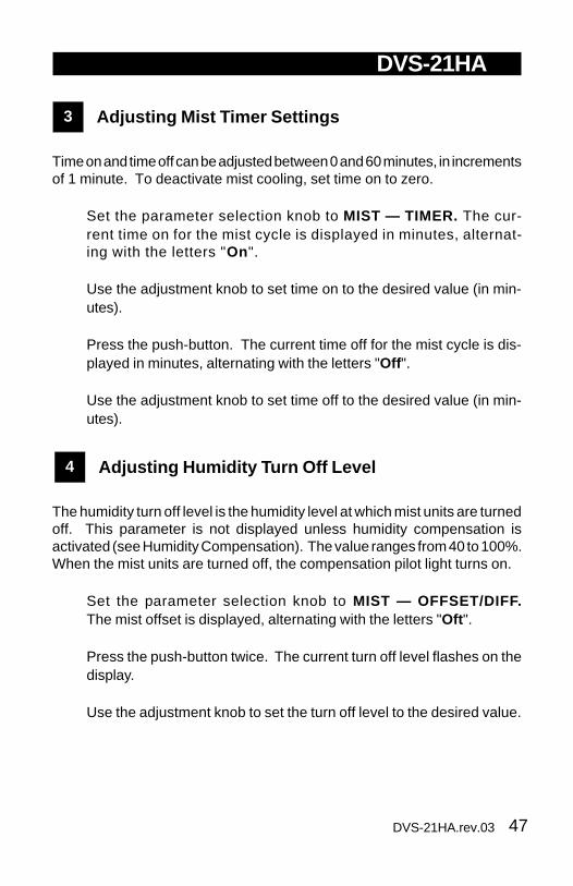
1 Adjusting Mist Offset
The mist offset is the temperature difference from the set point at which themist units turn off. The offset can be adjusted between 0.5°F and 40.0°F(0.3°C and 22.2°C).
n Set the parameter selectionknob to MIST — OFFSET/DIFF. The mist offset is dis-played, alternating with the let-ters "Oft ".
n Using the adjustment knob, set the offset to the desired value.
2 Adjusting Mist Differential
The mist differential is the variation in room temperature between the momentthe mist units turn on and the moment they turn off. The differential can beadjusted between 0.5°F and 20.0°F (0.3°C and 11.1°C).
n Set the parameter selection knob to MIST — OFFSET/DIFF. Themist offset is displayed, alternating with the letters "Oft ".
n Press the push-button. The mist differential is displayed, alternatingwith the letters "diF ".
n Using the adjustment knob, set the differential to the desired value.
47DVS-21HA.rev.03
DVS-21HA
3 Adjusting Mist Timer Settings
Time on and time off can be adjusted between 0 and 60 minutes, in incrementsof 1 minute. To deactivate mist cooling, set time on to zero.
n Set the parameter selection knob to MIST — TIMER. The cur-rent time on for the mist cycle is displayed in minutes, alternat-ing with the letters "On".
n Use the adjustment knob to set time on to the desired value (in min-utes).
n Press the push-button. The current time off for the mist cycle is dis-played in minutes, alternating with the letters "Off ".
n Use the adjustment knob to set time off to the desired value (in min-utes).
4 Adjusting Humidity Turn Off Level
The humidity turn off level is the humidity level at which mist units are turnedoff. This parameter is not displayed unless humidity compensation isactivated (see Humidity Compensation). The value ranges from 40 to 100%.When the mist units are turned off, the compensation pilot light turns on.
n Set the parameter selection knob to MIST — OFFSET/DIFF.The mist offset is displayed, alternating with the letters "Oft ".
n Press the push-button twice. The current turn off level flashes on thedisplay.
n Use the adjustment knob to set the turn off level to the desired value.

48 DVS-21HA.rev.03
HEATER SETTINGS
To use stage 3 for heating, set internal switch # 6 to ON.
If the room temperature rises:
- at Set Point - Heater 1 Offset: Heater 1 turns off.
If the room temperature falls:
- at Set Point - Heater 1 Offset - Heater 1 Diff.: Heater 1 turns on.
RoomTemperature
Heating
Set Point
Heater 1
HEATER 1DIFFERENTIAL
Heater 1 ON Heater 1 OFF
HEATER 1OFFSET
49DVS-21HA.rev.03
DVS-21HA
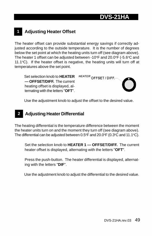
1 Adjusting Heater Offset
The heater offset can provide substantial energy savings if correctly ad-justed according to the outside temperature. It is the number of degreesbelow the set point at which the heating units turn off (see diagram above).The heater 1 offset can be adjusted between -10oF and 20.0oF (-5.6oC and11.1oC). If the heater offset is negative, the heating units will turn off attemperatures above the set point.
n Set selection knob to HEATER— OFFSET/DIFF. The currentheating offset is displayed, al-ternating with the letters "OFT".
n Use the adjustment knob to adjust the offset to the desired value.
2 Adjusting Heater Differential
The heating differential is the temperature difference between the momentthe heater units turn on and the moment they turn off (see diagram above).The differential can be adjusted between 0.5oF and 20.0oF (0.3oC and 11.1oC).
n Set the selection knob to HEATER 1 — OFFSET/DIFF. The currentheater offset is displayed, alternating with the letters "OFT".
n Press the push-button. The heater differential is displayed, alternat-ing with the letters "DIF".
n Use the adjustment knob to adjust the differential to the desired value.

50 DVS-21HA.rev.03
DVS-21HA
HUMIDITY COMPENSATION USING HEATER 1
Heater 1 can be used to reduce humidity levels under certain conditions.When the relative humidity is greater than the humidity set point, Heater 1operates according to a timer cycle as long as Stage 2 fans are not running.When the humidity drops to the humidity set point - 3%, Heater 1 turns off.This feature is enabled by setting internal switch # 9 to ON. The alternativeto using this feature is to compensate the Stage 1 minimum speed (seeVentilation Settings — only one of the two compensation methods can beused).
Heater 1 operates according to timer settings as shown below:
RelativeHumidity
RelativeHumiditySet Point
Heater 1 operatesaccording to timer settings
Heater 13%
Heater 1 turns off
ON
OFF
TIME ON
TIME OFF

51DVS-21HA.rev.03
DVS-21HA
1 Viewing Relative Humidity
The relative humidity is expressed as a percentage.
n Set the selection knob toSTAGE 1 — HUMIDITY. Thecurrent relative humidity is dis-played.
n Turn the adjustment knob clockwise by one notch. The minimumhumidity flashes on the display, alternating with the letters "Lo ".
n Turn the adjustment knob clockwise one notch further. The maximumhumidity flashes on the display, alternating with the letters "Hi".
n Turn the adjustment knob clockwise a third notch. The current humid-ity value is displayed again.
NOTE: If you let the display flash for more than 10 seconds when themaximum or minimum humidity is displayed, the controller resets the mini-mum and maximum humidity values currently in memory (the display stopsflashing to indicate that the reset has been done).
2 Activating / Deactivating Humidity Compensation
n Set the selection knob to STAGE 1 — HUMIDITY. The current humidityreading is displayed.
n Press the push-button. The current on/off state of humidity compensationflashes on the display.
n Use the adjustment knob to adjust the on/off state to the desired value.

52 DVS-21HA.rev.03
DVS-21HA
3 Adjusting Relative Humidity Set Point
When the relative humidity exceeds the humidity set point, Heater 1 turnson and operates according to the timer settings as long as Stage 2 fans arenot running. Note that the humidity compensation feature must be acti-vated for this to work.
n Set the selection knob to STAGE 1 — HUMIDITY. The current humidityreading is displayed.
n Press the push-button twice. The relative humidity set point isdisplayed, alternating with the letters "set rH ".
n Use the adjustment knob to adjust the set point to the desired value.
4 Adjusting Heater 1 Timer Settings
The timer is used to operate Heater 1 for humidity compensation. Time onand Time off can be adjusted from 0 to 900 seconds, in steps of 15 sec-onds.
n Set the selection knob to STAGE 1 — HUMIDITY . The current humidityreading is displayed.
n Press the push-button three times. The current time on is displayed,alternating with the word "On".
n Use the adjustment knob to adjust the time on to the desired value.
n Press the push-button. The current time off is displayed, alternatingwith the word "OFF".
n Use the adjustment knob to adjust the time off to the desired value.

53DVS-21HA.rev.03
ALARM SETTINGS
The controller sets off an alarm in the case of a power failure, a fault in thesupply circuit or a high or low temperature. Temperature alarms are de-fined according to the set point as shown in the diagram below.
Adjusting the Alarm Settings
The high and low alarm offsets range from 0.5oF to 40oF.
n Set the selection knob to ALARMOFFSETS. The current low alarmoffset flashes on the display, al-ternating with the word "LO".
n Use the adjustment knob to set the low alarm offset to the desiredvalue.
RoomTemperature
Set PointHigh Alarm Offset
Time
High Temperature Alarm
Low Alarm Offset
ALARM OFFSETS
If an INTERFACE-3 is connected to the DVS-21HA to monitor the outsidetemperature, the high alarm is handled differently. When the outsidetemperature is greater than the set point, the set point is replaced by theoutside temperature as the reference point. This means an alarm is set offwhen the indoor temperature reaches Outside Temperature + High AlarmOffset. A third parameter, called the critical high temperature, is defined tocontinue monitoring the indoor temperature for high temperatures. Whenthe indoor temperature reaches the critical high temperature (defined asan absolute value), an alarm is set off.

54 DVS-21HA.rev.03
DVS-21HA
n Press the push-button. The current high alarm offset flashes on thedisplay, alternating with the word "HI".
n Use the adjustment knob to set the high alarm offset to the desiredvalue.
n If an INTERFACE-3 is connected to the DVS-21HA, press the push-button. The current critical high temperature is displayed, alternatingwith the letters "Cri ".
n Use the adjustment knob to set the critical high temperature to thedesired value.
55DVS-21HA.rev.03
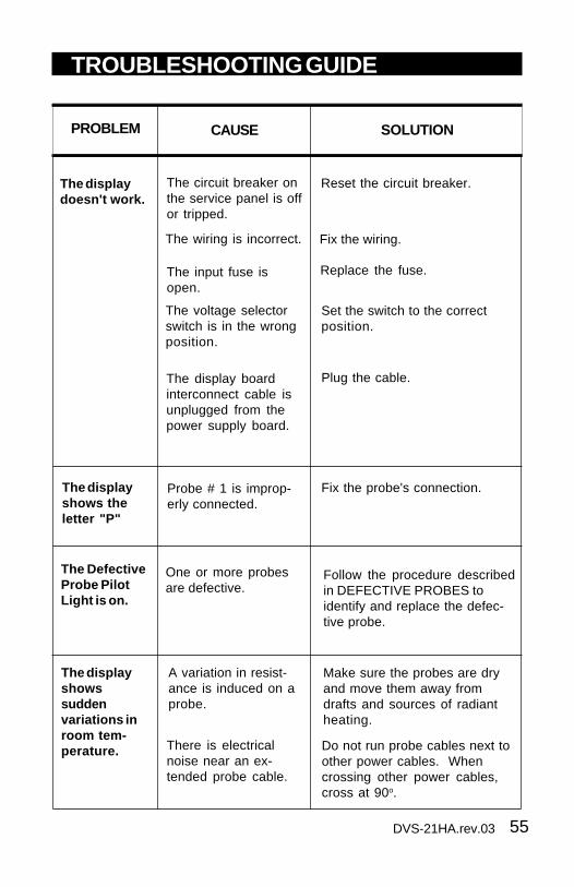
The displayshowssuddenvariations inroom tem-perature.
A variation in resist-ance is induced on aprobe.
There is electricalnoise near an ex-tended probe cable.
Make sure the probes are dryand move them away fromdrafts and sources of radiantheating.
Do not run probe cables next toother power cables. Whencrossing other power cables,cross at 90o.
TROUBLESHOOTING GUIDE
PROBLEM CAUSE SOLUTION
The DefectiveProbe PilotLight is on.
One or more probesare defective.
Follow the procedure describedin DEFECTIVE PROBES toidentify and replace the defec-tive probe.
The display boardinterconnect cable isunplugged from thepower supply board.
The voltage selectorswitch is in the wrongposition.
The input fuse isopen.
The circuit breaker onthe service panel is offor tripped.
The displaydoesn't work.
Reset the circuit breaker.
Replace the fuse.
Set the switch to the correctposition.
Plug the cable.
The displayshows theletter "P"
Probe # 1 is improp-erly connected.
Fix the probe's connection.
The wiring is incorrect. Fix the wiring.

56 DVS-21HA.rev.03
DVS-21HA
SOLUTIONPROBLEM CAUSE
The wiring is incor-rect.
Correct the wiring. In particular,make sure two different lines areconnected to each motor: line L1modulated by the controllershould be combined with anotherline (N for 115V or L2 for 230V) toactivate the motor. Also, be surethe Stage 1 and 2 COMMON issupplied by line L1.
The Stage's fuse isopen.
Replace the fuse.
Make sure the cable is firmlyplugged in with the tabs inplace.
The display boardinterconnect cable isnot plugged into thepower supply boardproperly.
The fan motor isdefective.
Check if motor is defective byconnecting it to an alternatepower supply. Replace themotor if it still doesn't operate.
The minimum speedis too low.
Adjust the minimum speed to ahigher value.
Stage 1 or 2fans are notrunning.
57DVS-21HA.rev.03
DVS-21HA
SOLUTIONPROBLEM CAUSE
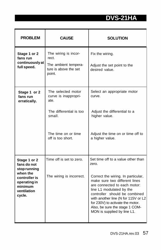
Stage 1 or 2fans runcontinuously atfull speed.
The wiring is incor-rect.
The ambient tempera-ture is above the setpoint.
Fix the wiring.
Adjust the set point to thedesired value.
Stage 1 or 2fans runerratically.
The selected motorcurve is inappropri-ate.
Select an appropriate motorcurve.
The differential is toosmall.
Adjust the differential to ahigher value.
The time on or timeoff is too short.
Adjust the time on or time off toa higher value.
Time off is set to zero. Set time off to a value other thanzero.
Stage 1 or 2fans do notstop runningwhen thecontroller isoperating inminimumventilationcycle.
The wiring is incorrect. Correct the wiring. In particular,make sure two different linesare connected to each motor:line L1 modulated by thecontroller should be combinedwith another line (N for 115V or L2for 230V) to activate the motor.Also, be sure the stage 1 COM-MON is supplied by line L1.

58 DVS-21HA.rev.03
DVS-21HA
CAUSE SOLUTION
The Stage's fuse isopen.
Replace the fuse.
The display boardinterconnect cable isnot plugged into thepower supply boardproperly.
Make sure the cable is firmlyplugged in with the tabs in place.
The wiring is incor-rect.
Correct the wiring. In particular,make sure two different linesare connected to each motor:line L1 modulated by thecontroller should be combinedwith another line (N for 115V or L2for 230V) to activate the motor orheating unit. Also, make sure theStage COMMON is supplied byline L1.
Verify if the motor or heating unitis defective by connecting it toan alternate power supply.Replace the motor or heatingunit If it still is not operating.
The fan motor orheating unit isdefective.
The controller isdefective.
Listen to see if there is a clickingsound when the Stage's pilotlight turns on. If there is noclicking sound, contact yourdistributor to repair the control-ler.
PROBLEM
Stage 3 is notoperating.

59DVS-21HA.rev.03
DVS-21HA
CAUSE SOLUTIONPROBLEM
The internal switchesare improperly set.
Verify the internal switchsettings.
Stage 3 is notrunning asexpected.
60 DVS-21HA.rev.03
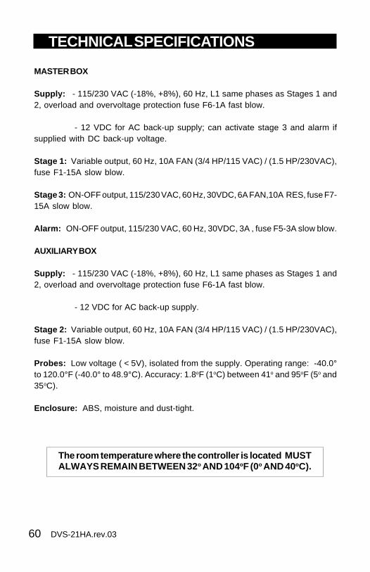
TECHNICAL SPECIFICATIONS
The room temperature where the controller is located MUSTALWAYS REMAIN BETWEEN 32 o AND 104oF (0o AND 40oC).
MASTER BOX
Supply: - 115/230 VAC (-18%, +8%), 60 Hz, L1 same phases as Stages 1 and2, overload and overvoltage protection fuse F6-1A fast blow.
- 12 VDC for AC back-up supply; can activate stage 3 and alarm ifsupplied with DC back-up voltage.
Stage 1: Variable output, 60 Hz, 10A FAN (3/4 HP/115 VAC) / (1.5 HP/230VAC),fuse F1-15A slow blow.
Stage 3: ON-OFF output, 115/230 VAC, 60 Hz, 30VDC, 6A FAN,10A RES, fuse F7-15A slow blow.
Alarm: ON-OFF output, 115/230 VAC, 60 Hz, 30VDC, 3A , fuse F5-3A slow blow.
AUXILIARY BOX
Supply: - 115/230 VAC (-18%, +8%), 60 Hz, L1 same phases as Stages 1 and2, overload and overvoltage protection fuse F6-1A fast blow.
- 12 VDC for AC back-up supply.
Stage 2: Variable output, 60 Hz, 10A FAN (3/4 HP/115 VAC) / (1.5 HP/230VAC),fuse F1-15A slow blow.
Probes: Low voltage ( < 5V), isolated from the supply. Operating range: -40.0°to 120.0°F (-40.0° to 48.9°C). Accuracy: 1.8oF (1oC) between 41o and 95oF (5o and35oC).
Enclosure: ABS, moisture and dust-tight.

61DVS-21HA.rev.03
FACTORY SETTINGS
RETEMARAPYROTCAFGNITTES
FOEGNARSEULAV
tnioPteSerutarepmeT 57 o 9.32(F o )C9.99ot04- o F7.73ot04-( o )C
1egatS
muminiMdeepS
%04 %001ot%01
nOemiT sdnoces51 ybsdnoces009ot051fostnemercni
sdnocesffOemiT sdnoces0
htdiwdnaB 3 o 7.1(F o )C02ot5.0 o F
1.11ot3.0( o )C
ytidimuHlortnoC
teSytidimuHtnioP
%56%001ot04
ytidimuhevitaler
noitasnepmoCegatnecreP
%0muminimfo%001ot0
deeps
1retaeHnOemiT
sdnoces0 ybsdnoces009ot051fostnemercni
sdnoces1retaeHffOemiT
sdnoces0
2egatS
tesffO 5.0 o 3.0(F o )C02ot02- o F
1.11ot1.11-( o )C
htdiwdnaB 2 o 1.1(F o )C02ot5.0 o F
1.11ot3.0( o )C
deepS.niM %04 %001ot01
nOemiT sdnoces0 ybsdnoces009ot051fostnemercni
sdnocesffOemiT sdnoces0
3egatS laitnereffiD 2 o 1.1(F o )C02ot5.0 o F
1.11ot3.0( o )C

62 DVS-21HA.rev.03
DVS-21HA
NOTES:
i) These initial parameter settings will not be retained in the controller'smemory. Each new setting will replace the preceding one.
ii) If the power supply is cut off, the last parameter settings will be re-tained in memory until the power is restored.
RETEMARAPYROTCAFGNITTES
FOEGNARSEULAV
tsiM
nOemiT setunim0 yb,setunim06ot01fostnemercni
etunimffOemiT setunim0
tesffO )C°7.6(F°2104ot5.0 o F
2.22ot3.0( o )C
laitnereffiD 2 o 1.1(F o )C02ot5.0 o F
1.11ot3.0( o )C
nruTytidimuHleveLffO
%59 %001ot04
retaeH
tesffO 5.0 o 3.0(F o )C02ot01- o F
1.11ot6.5-( o )C
laitnereffiD 2 o 1.1(F o )C02ot5.0 o F
1.11ot3.0( o )C
smralA
tesffOhgiH 0.21 o 7.6(F o )C04ot5.0 o F
2.22ot3.0( o )C
tesffOwoL 0.01 o 6.5(F o )C04ot5.0 o F
2.22ot3.0( o )C
.pmeTlacitirC 9.99 o 7.73(F o )C9.99ot04- o F7.73ot04-( o )C

63DVS-21HA.rev.03
NOITISOP YALPSID GNINAEM
MOORERUTAREPMET
eulavydaets erutarepmetmooR
FFO/nO-1rPFFO/nO-2rPFFO/nO-3rPFFO/nO-4rP
xeborprofetatsffo/nodnaerutarepmetmooR
iH/oL .eulaverutarepmetmumixaM/muminiM
°T/TNIOPTESEVRUC
eulavgnihsalf .tnioptesdetsujda-resU
eulavydaetserutarepmetehtgnisudetaluclactniopteS
.evruc
FFO/nO .evrucerutarepmetfosutatS
YAdevrucerutarepmettnerrucehtforebmunyaD
.tniop
tes .tniopevrucerutarepmettnerrucehtfotniopteS
FUNCTION SUMMARY
64 DVS-21HA.rev.03
DVS-21HA
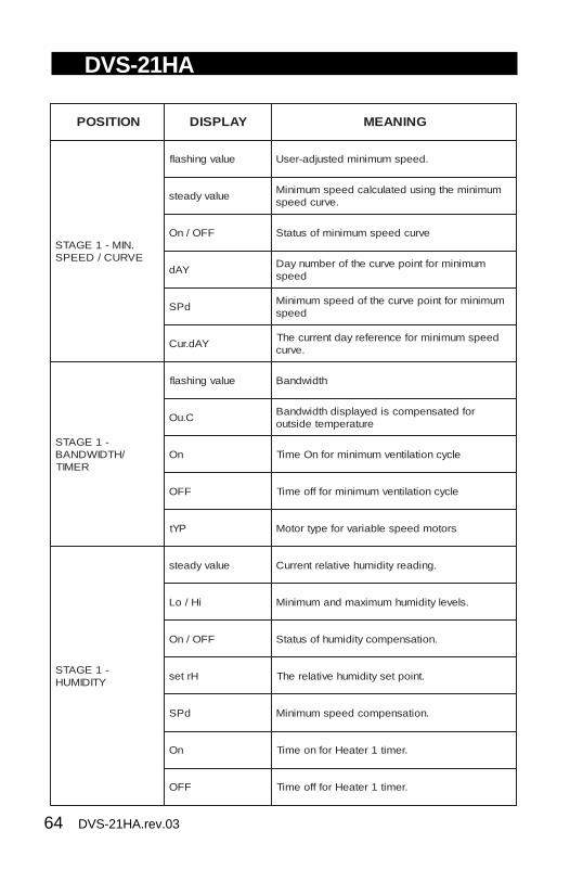
NOITISOP YALPSID GNINAEM
.NIM-1EGATSEVRUC/DEEPS
eulavgnihsalf .deepsmuminimdetsujda-resU
eulavydaetsmuminimehtgnisudetaluclacdeepsmuminiM
.evrucdeeps
FFO/nO evrucdeepsmuminimfosutatS
YAdmuminimroftniopevrucehtforebmunyaD
deeps
dPSmuminimroftniopevrucehtfodeepsmuminiM
deeps
YAd.ruCdeepsmuminimrofecnereferyadtnerrucehT
.evruc
-1EGATS/HTDIWDNAB
REMIT
eulavgnihsalf htdiwdnaB
C.uOrofdetasnepmocsideyalpsidhtdiwdnaB
erutarepmetedistuo
nO elcycnoitalitnevmuminimrofnOemiT
FFO elcycnoitalitnevmuminimrofffoemiT
PYt srotomdeepselbairavrofepytrotoM
-1EGATSYTIDIMUH
eulavydaets .gnidaerytidimuhevitalertnerruC
iH/oL .slevelytidimuhmumixamdnamuminiM
FFO/nO .noitasnepmocytidimuhfosutatS
Hrtes .tnioptesytidimuhevitalerehT
dPS .noitasnepmocdeepsmuminiM
nO .remit1retaeHrofnoemiT
FFO .remit1retaeHrofffoemiT

65DVS-21HA.rev.03
DVS-21HA
NOITISOP YALPSID GNINAEM
-2EGATS/TESFFO
HTDIWDNAB
tfO .tesffo2egatS
db htdiwdnaB
PYt .srotomdeepselbairavrofepytrotoM
.NIM-2EGATSDEEPS
eulavgnihsalf .deepsmuminiM
nO .noemiT
ffO .ffoemiT
3EGATSLAITNEREFFID
3.tS 3egatsroflaitnereffiD
TSIMREMIT
nO .elcyctsimrofnoemiT
ffO .elcyctsimrofffoemiT
TSIM.FFID/TESFFO
PtS/tfO .)erutarepmetpots(tesffotsiM
rtS/Fid .)erutarepmettrats(laitnereffidtsiM
eulavgnihsalf .levelffonrutytidimuH
-1TAEH.FFID/TESFFO
PtS/tfO .)erutarepmetpots(tesffo1retaeH
rtS/Fid .)erutarepmettrats(laitnereffid1retaeH
STESFFOMRALA
oL .tesffomralawoL
iH .tesffomralahgiH
.irC .erutarepmetlacitirC