temperature controller e5 j - omron · temperature controller e5 j fuzzy self-tuning temperature...
TRANSCRIPT

1
Temperature Controller E5 JFuzzy Self-tuning TemperatureController with Advanced PID (2-PID)Control
DIN-size:96 x 96 mm (E5AJ), 72 x 72 mm (E5BJ),48 x 48 mm (E5CJ), 48 x 96 mm (E5EJ)
Fuzzy self-tuning and Auto-tuning optimize temper-ature control.
Minimal user setup.
Dual set point, selectable by external input.
RUN/STOP operation (E5AJ/E5EJ) by externalinput.
Front panel protection conforming to IP54 onE5AJ/E5EJ/E5BJ (IP66/NEMA4 with optionalcover). E5CJ conforms to IP50 (IP66/NEMA4 withoptional cover).
Serial communications models (E5AJ/E5EJ).
Relay, voltage or linear outputs.
Conforms to international EMC and safetystandards.
RC
Ordering Information Temperature Controllers
E5AJ/EJ/BJItem Standard type
Two alarmt t t t
Communications type CommunicationsBoard add-on type
outputs; two eventinputs (with heater
burnout alarm)
RS-232C RS-422 RS-485
Model E5AJ-A2HBE5EJ-A2HBE5BJ-A2HB
E5AJ-A2H01E5EJ-A2H01
E5AJ-A2H02E5EJ-A2H02
E5AJ-A2H03E5EJ-A2H03
E5AJ-A2HME5EJ-A2HM
Note: 1. Be sure to specify Control Output Unit and Current Transformer as necessary when ordering.Example: E5AJ-A2HB, Relay Output Unit E53-R, Current Transformer E54-CT1
2. The heater burnout alarm is not available when the E5J is used with Linear Output Units.
3. Ask your OMRON representative for the E5AJ/E5EJ Communications Manual (Z102) when using a model incorporating a commu-nications function.
4. Be sure to specify Communications Boards as necessary when ordering E5AJ/EJ-A2HM Communications Board add-on types.
Control Output Unit (Required for E5AJ, E5BJ, and E5EJ)
Type Relay Output Unit Voltage Output Unit (for SSR drive)
Current Output Unit
Model E53-R E53-Q E53-C3
Communications BoardsWhen communications capability is required, mount one of the following Boards on the E5AJ-A2HM or E5EJ-A2HM.
Communications RS-232C RS-422 RS-485
Model E53-J01 E53-J02 E53-J03
Note: For details, refer to the E5AJ/E5EJ Communications Manual (Z102).

E5J E5J
2
E5CJItem Standard type Single-function type
Two alarm points; one event input Two alarm points; without eventinput
Without alarm and event input
Relayoutput
Voltageoutput
Currentoutput
Relayoutput
Voltageoutput
Currentoutput
Relayoutput
Voltageoutput
Currentoutput
Model E5CJ-R2HB E5CJ-Q2HB E5CJ-C2B E5CJ-R2 E5CJ-Q2 E5CJ-C2 E5CJ-R E5CJ-Q E5CJ-C
Note: Be sure to specify Current Transformer as necessary when ordering E5CJ-R2HB and E5CJ-Q2HB.The heater burnout alarm is not available for models other than E5CJ-R2HB and E5CJ-Q2HB.
Current Transformers (CT) (Order Separately)Hole diameter 5.8 mm 12.0 mm
Model E54-CT1 E54-CT3
Note: No CT is required unless the heater burnout alarm function is used.
Terminal Covers (Order Separately)Model E5AJ E5EJ E5CJ
Connectable models E53-COV02 E53-COV03 E53-COV04
Temperature RangesInput (switch selectable)
Temperature-resistancethermometer
Thermocouple( )
JPt100Platinum
resistancethermometer
Pt100Platinum
resistancethermometer
K (CA)Chromel vs.
alumel
J (IC)Iron vs.
constantan
T (CC)Copper vs.constantan
LIron vs.
constantan
UCopper vs.constantan
NNichrosilvs. nisil
Built-inswitch
Default set-ting; 2(K)
Tem
pera
ture
ran
ge
1,300900800600400300200100
0–100–200
°C
–199.9
650.0
–199.9
650.0
–200
1,300
–100
850
–199.9
400.0
–100
850
–199.9
400.0
–200
1,300
SettingNo.
0 1 2 3 4 5 6 7
Minimumsetting unit
Targetvalue
0.1°C 1°C 1°C 0.1°C 1°C 0.1°C 1°Cg
Alarm 0.1°C 1°C 1°C 0.1°C 1°C 0.1°C 1°C
Note: Default setting: 2 (K).

E5J E5J
3
Specifications Ratings
Supply voltage 100 to 240 VAC, 50 or 60 Hz 24 V AC/DC, 50 or 60 Hz
Operating voltage range 85% to 110% of rated supply voltage
Power consumption E5AJ/E5EJ: 10 VA (at 100 VAC) to 14 VA (at 240 VAC)E5BJ/E5CJ: 10 VA (at 100 VAC) to 12 VA (at 240 VAC)
10 VA (at 24 VAC)6 W (at 24 VDC)
Input Thermocouple (K/J/T/L/U/N) or platinum resistance thermometer (JPt100/Pt100), selectable
Current T ransformer input Connect an exclusive Current Transformer unit (E54-CT1 or E54-CT3)
Controlt t
E5AJ/E5BJ/E5EJ Replaceable Output Unit (sold separately)Co ooutput E5CJ Relay output SPST-NO, 3 A at 250 VAC (resistive load)5CJ
Voltage output 20 mA at 12 VDC (with short-circuit protection)
Current output 4 to 20 mA DC with a load of 600 Ω max. and a resolution of approx. 2600
Control mode ON/OFF or PID control (2-PID) with fuzzy self-tuning and auto-tuning
Alarm output E5AJ/E5EJ: Relay output, 2 independent SPST-NO contacts; 3 A, 250 VACE5BJ/E5CJ: Common 2 outputs, 2 independent SPST-NO contacts;
E5CJ: 1 A, 250 VAC; E5BJ: 3 A, 250 VAC
Setting method Digital setting via Up and Down Keys
Indication method Digital indications Character heights: E5AJ: PV: 15 mm, SV: 10.5mm
E5EJ/E5BJ: PV: 14 mm, SV: 9.5 mmE5CJ: PV: 12 mm, SV: 8 mm
Event input Contact input: ON: 1 kΩ max., OFF: 100 kΩ min.No-contact input: ON: residual voltage: 3 V max., OFF: leakage current: 1 mA max.
Other functions Key protectionDirect and reverse output selectionMultiple SP (four set points; up to four set points available on E5AJ/E5EJ by engineering level)RUN/STOP (selected via external terminals) (E5AJ, E5EJ)Heater burnout detection
Note: It is possible to add other functions from the engineering level. Refer to the E5J Operation Manual, obtainable from your OMRONrepresentative, for details.

E5J E5J
4
CharacteristicsIndication accuracy (see note 1) (±0.5% of indication value or ±1°C, whichever greater) ±1 digit max.
Hysteresis 0.1° to 999.9°C/°F (in units of 0.1°C/°F) (during ON/OFF control action)
Proportional band 0.1° to 999.9°C/°F (in units of 0.1°C/°F)
Integral (reset) time 0 to 3,999 s (in units of 1 s)
Derivative (rate) time 0 to 3,999 s (in units of 1 s)
Alarm output setting range Thermocouple (K/J/L/N): –1,999° to 9,999°C/°F (in units of 1°C/°F)Platinum resistance thermometer, thermocouple (T/U): –199.9° to 999.9°C/°F (in units of 0.1°C/°F)
Control period Pulse output: 1 to 99 s (in units of 1 s)
Sampling period 500 ms
Output refresh time 500 ms
Display refresh time 500 ms
Insulation resistance (see note 2) 20 MΩ min. (at 500 VDC)
Dielectric strength 2,000 VAC, 50/60 Hz for 1 min between terminals of different polarities
Vibration resistance Malfunction: 10 to 55 Hz, 9.8 m/s2 (1G) for 10 min each in X, Y, and Z directionsDestruction: 10 to 55 Hz, 19.6 m/s2 (2G) for 2 hrs each in X, Y, and Z directions
Shock resistance Malfunction: 196 m/s2 (20G), 3 times each in 6 directions(98 m/s2 (10G) applied to the relay)
Destruction: 294 m/s2 (30G), 3 times each in 6 directions
Life expectancy Mechanical: 10,000,000 operations (relay alarm output)Electrical: 100,000 operations (relay alarm output)
Ambient temperature Operating: –10°C to 55°C (with no icing)Storage: –25°C to 65°C (with no icing)
Ambient humidity Operating: 35% to 85%
Memory protection Non-volatile memory (number of write operations: 100,000)
Enclosure ratings Front panel: E5AJ/E5EJ/E5BJ: IEC standard IP54E5CJ: IEC standard IP50 (see note 3)
Rear case: IEC standard IP20Terminals: IEC standard IP00
Weight E5AJ: Approx. 360 g, E5EJ: Approx. 280 g, E5BJ: Approx. 240 g, E5CJ: Approx. 170 g;Mounting adapter for E5CJ: approx. 10 g;Mounting bracket for E5AJ, E5BJ, and E5EJ: Approx. 65 g
EMC Emission Enclosure: EN55011 Group 1 class AEmission AC Mains: EN55011 Group 1 class AImmunity ESD: EN61000-4-2: 4-kV contact discharge (level 2)
8-kV air discharge (level 3)Immunity RF-interference: ENV50140: 10 V/m (amplitude modulated,
80 MHz to 1 GHz) (level 3)10 V/m (pulse modulated, 900 MHz)
Immunity Conducted Disturbance: ENV50141: 10 V (0.15 to 80 MHz) (level 3)Immunity Burst: EN61000-4-4: 2-kV power-line (level 3)
2-kV I/O signal-line (level 4)
Approved standards UL1092, CSA C22.2 No. 142Conforms to EN50081-2, EN50082-2, EN61010-1 (IEC1010-1) (see note 4)Conforms to VDE0106/part 100 (Finger Protection), when the separately-ordered terminalcover is mounted.
Note: 1. The indication accuracy of the K, T, and N thermocouples at a temperature of –100°C or less is ±2°C±1 digit maximum. The indica-tion accuracy of the U thermocouple at any temperature is ±2°C±1 digit maximum.
2. The insulation resistance was measured with a Control Output Unit attached.
3. The model numbers of the exclusive watertight covers conforming to IP66, NEMA4 are as follows:For E5AJ: Y92A-96N; For E5BJ: Y92A-72N; For E5CJ: Y92A-48N; For E5EJ: Y92A-49N
4. Basic insulation is between the input and output.

E5J E5J
5
Output Unit RatingsNo event input is photoelectrically insulated from the voltage or current output.
Relay Output Unit (see note 2) E53-R SPDT, 5 A at 250 VAC (resistive load)
Voltage Output Unit (for driving SSR) E53-Q NPN, 40 mA at 12 VDC (with short-circuit protection)
E53-Q3 NPN, 20 mA at 24 VDC (with short-circuit protection)
E53-Q4 PNP, 20 mA at 24 VDC (with short-circuit protection)
Linear Output Unit (see note 1 and 3) E53-C3 4 to 20 mA; DC: 600 Ω max.; resolution: approx. 2,600
E53-C3D 0 to 20 mA; DC: 600 Ω max.; resolution: approx. 2,600
E53-V34 0 to 10 V; DC: 1 kΩ min.; resolution: approx. 2,600
E53-V35 0 to 5 V; DC: 1 kΩ min.; resolution: approx. 2,600
Note: 1. The current output is not a transmission output.The heater burnout alarm cannot be used with the E53-C Current Output Units.
2. The contact configuration will be SPST-NO when used with the E5J.
3. No heater burnout alarm is available if the Linear Output Unit is used with the E5J.
Heater Burnout AlarmMax. heater current Single-phase 50 A VAC (see note 1)
Heater current value display accuracy ±5% FS ±1 digit max.
Heater burnout alarm setting range 0.1 to 49.9 A (in units of 0.1 A) (see note 2)
Min. detection ON time 190 ms (see note 3)
Note: 1. Use the K2CU-FA-GS (with gate input terminals) for the detection of three-phase heater burnout.
2. The heater burnout alarm is always OFF if the alarm is set to 0.0 A and always ON if the alarm is set to 50.0 A.
3. No heater burnout detection or heater current value measurement is possible if the control output is ON for less than 190 ms.
Current Transformer RatingsMax. continuous heater current 50 A
Dielectric strength 1,000 VAC
Vibration resistance 50 Hz, 98 m/s2 (10G)
Weight E54-CT1: Approx. 11.5 g; E54-CT3: Approx. 50 g
Accessories (E54-CT3 only) Contact: 2; Plug: 2
Output Unit CharacteristicsRelay unit life expectancy Mechanical: 10,000,000 operations min.
Electrical: 100,000 operations min.
Communications (E5AJ/E5EJ)Protocol RS-232C, RS-422, RS-485
Transmission method Half-duplex
Synchronization method Start-stop synchronization (asynchronous method)
Baud rate 1,200/2,400/4,800/9,600/19,200 bps
Transmission code ASCII
Communications Write to T emperature Controller Set point, alarm value, remote/local selection etc. (proportional band,integral time, derivative time)
Read from Temperature Controller Process value, output value, set point, alarm value, heater currentvalue, initial status, etc. (proportional band, integral time, derivativetime)
Note: 1. The maximum total cable length must not exceed the following limits.RS-422: 500 m, RS-232C: 15 m, RS-485: 500 m
2. The number of connecting Units including the host computer via RS-485 is 32. The number of connecting Units via RS-422 is 32.

E5J E5J
6
NomenclatureE5CJ
Lights when the control out-put is ON. In current outputmode, however, the outputindicator will not be lit.
Set Value (SV) DisplayDisplays the set temperatureand set value of each settingitem.
Output Indicator
Level KeyPress for 1 second minimum tochange levels to set differentgroups of parameters.
Display Key
Press to shift the displayto the next parameter.
Process V alue (PV) displayDisplays the process value, the charac-ter for the parameter being displayedon the SV display, and error messages.
Heater Burnout IndicatorLights when a heater burnout isdetected and stays lit until reset.
Alarm 1 IndicatorLights when alarmoutput 1 is ON.
Alarm 2 IndicatorLights when alarmoutput 2 is ON.
Down and Up KeysPress to increase or decrease the value on the SV display. Successivelyincreases or decreases the value when held down for 1 s or more. Thevalue set will be effective automatically in 2 s or immediately after pressingthe Display Key or Level Key.
Note: There are models that do not incorporateHB, ALM1, and ALM2 indicators.
E5AJ/E5BJ/E5EJ
Lights when the control out-put is ON. In current outputmode, however, the outputindicator will not be lit.
Lights when the TemperatureController is not in operation.The E5BJ or any other E5Jmodel with a communicationsfunction does not incorporate astop indicator.
Heater Burnout Indicator
Output Indicator
Level KeyPress for 1 second mini-mum to change levels toset different groups ofparameters.Display Key
Press to shift the displayto the next parameter.
Stop Indicator
Process V alue (PV) displayDisplays the process value, thecharacter for the parameter beingdisplayed on the SV display, anderror messages.
Set Value (SV) Display
Displays the set temperatureand set value of each settingitem.
Alarm 1 IndicatorLights when alarmoutput 1 is ON.
Alarm 2 IndicatorLights when alarm output2 is ON.
Lights when a heater burnout isdetected and stays lit until reset.
Down and Up KeysPress to increase or decrease the value on the SV display.Successively increases or decreases the value when held downfor 1 s or more. The value set will be effective automatically in 2 sor immediately after pressing the Display Key or Level Key.

E5J E5J
7
OperationNOTICE: Always turn off the power supply to the Temperature Controller before changing any switch settings.
SettingsE5CJRemove the internal mechanism from the housing. Pull out the inter-nal mechanism while pressing the hook at the bottom of the frontpanel.
Internal Switches
E5CJ
Top View
Bottom View
Note: A model with no alarm does not incorporatean alarm mode selector.
Alarm mode selector 2(ALM2) (see note)
Alarm mode selector 1(ALM1) (see note)
Input type selector(INPUT)
Key protection switch(PROTECT)
Function selector(FUNCTION)
E5AJ/E5BJ/E5EJ1. Remove the internal mechanism from the housing. Pull out
the internal mechanism while pressing the hook at the bottomof the front panel.
Hook
Pull out the internal mechanismwhile holding down the hook withyour finger.When inserting the internalmechanism back into the case,push the internal mechanism intothe case until it clicks into place.
2. Connect a Control Output Unit to the vacant socket on theprinted circuit board as shown below.
Mount the Control Output Unitwith the mark facing the direc-tion indicated by the arrow.Be sure to secure the outputunit with the provided fixture.
To remove a Control Output Unit, push it up with the tip of a flat-bladescrewdriver as shown below.
Flat-bladescrewdriver
Internal Switches
E5AJ
Top ViewAlarm mode selector 2(ALM2)
Alarm mode selector 1(ALM1)
Key protection switch(PROTECT)
Input type selector(INPUT)
Function selector(FUNCTION)
Bottom View

E5J E5J
8
Input type selector(INPUT)
Alarm mode selector 2(ALM2)
Alarm mode selector 1(ALM1)
Function selector(FUNCTION)
Key protection switch(PROTECT)
E5BJ
Top View
Bottom View
Alarm mode selector 2(ALM2)
Key protection switch(PROTECT)
Alarm mode selector 1(ALM1)
Input type selector(INPUT)
Function selector(FUNCTION)
E5EJ
Top View
Bottom View
Input Type Selector (INPUT)
This selector selects the temperature sensor to be used. It is facto-ry-set to position 2 to designate a K-type (chromel-alumel thermo-couple) temperature sensor. The following table lists the other pos-sible settings for temperature sensors. Refer to temperature rangecharts under Ordering Information for further information.
Switchtti
Temperatured
Temperature rangeS csetting
e pe a u esensor code °C °F
0, 8 JPt100 –199.9to650.0 –199.9 to 999.9
1, 9 Pt100 –199.9to650.0 –199.9 to 999.9
2 K –200 to1,300 –300 to 2,300
3 J –100 to 850 –100 to 1,500
4 T –199.9to400.0 –199.9 to 700.0
5 L –100 to 850 –100 to 1500
6 U –199.9to400.0 –199.9 to 700.0
7 N –200 to1,300 –300 to 2,300
Note: JPt100:139.16 Ω at 100°CPt100: 138.50 Ω at 100°C
Temperature Control in Fahrenheit1. After setting all internal switch settings, set pin number 4 of
the function switch to ON. This pin is normally set to OFF.
2. Insert the internal mechanism into the housing and turn on theTemperature Controller.
3. du will be displayed. Then press the Up Key to change theset value display into Fahrenheit “f.”
4. Turn off the power 2 s after the set value display has changedto Fahrenheit.
5. Remove the internal mechanism from the housing, set pinnumber 4 of the function switch to OFF, replace it and turn onthe power.
Function Selector (FUNCTION)
1 2 3 4
ON
ON
OFF
The DIP switch sets the operating parameters listed in the followingtable. All pins are factory-set to OFF.
Function selector pinnumber
1 2 3 4
Outputoperation
Normal (see note 1)
ON --- --- ---p
Reverse (seenote 1)
OFF --- --- ---
Controld
ON/OFF --- ON --- ---Co omode Advanced
PID--- OFF --- ---
PIDtuningmode
Withauto-tuning(see note 2)
--- --- ON (see
note 3)
---
With fuzzyself-tuning
--- --- OFF (see
note 3)
---
Level Engineeringlevel
--- --- --- ON
Normaloperation
--- --- --- OFF
Factory setting OFF OFF OFF OFF
Note: 1. For heating applications, use the reverse operationmode. For cooling applications use the normal opera-tion mode. (In other cases, select the desired setting.)
2. To start auto-tuning, press the Level and Display Keyssimultaneously, for 1 s or longer to start auto-tuning.During auto-tuning, the set value display flashes. (Thedisplay will stop flashing after tuning is finished.)
3. If the control mode is ON/OFF, pin 3 can be set ON orOFF. (Pin 3 is not important in case of ON/OFF control.)

E5J E5J
9
Alarm Mode Selectors (ALM1, ALM2)Alarm modes, listed in the following table, can be selected using this switch. The switch is factory-set to position 2, i.e., the upper-limit alarmmode.
Switch Mode Alarm output Setting range
setting Alarm operation When X is positive When X is negative
0 No alarm OFF ---
1 Upper- and lower-limit alarm(deviation)
X XON
OFF SP
Always ON –1999 to 9999, or –199.9 to 999.9(The decimal position varies withthe input type.)
2 Upper-limit alarm (deviation) X
SP
X
SP
3 Lower-limit alarm (deviation) X
SP
X
SP
4 Upper- and lower-limit alarm(deviation)
X X
SP
Always OFF
5 Upper- and lower-limit alarm withstandby sequence (deviation)
X X
SP
Always OFF
6 Upper-limit alarm with standbysequence (deviation)
X
SP
X
SP
7 Lower-limit alarm with standbysequence (deviation)
X
SP
X
SP
8 Absolute-value upper-limit alarm
0°C/°F
X
0°C/°F
X
9 Absolute-value lower-limit alarm
0°C/°F
X
0°C/°F
X
Deviation AlarmIf the alarm mode selector is set to a number between 1 to 7, alarmvalues are set to the width deviated from the set point as shown inthe following illustration.
Set point (SP)100°C/°F
Alarm value
10°C/°F
110°C/°F
Absolute AlarmIf the alarm mode selector is set to 8 or 9, alarm values are set to theabsolute value based on 0°C/°F as shown in the following illustra-tion.
0°C/°F
Alarm value
110°C/°F
110°C/°F

E5J E5J
10
Key Protection Switch (PROTECT)The key protection switch is factory-set to the OFF position.
SP OFF ALL
To write-protect set values, the settings of the protect modes must be changed.
Mode Protection
SP All set values other than the set point will be write-protected.
The Level Key will not be valid. The Down and Up Keys will not be valid except set point setting.
OFF No key protection will be valid.
All keys will work normally.
ALL All set values will be write-protected.
The Level, Down, and Up Keys will not be valid.
Inputting ParametersThe temperature Controller has two display levels 0 and 1, in which only specific parameters can be set. Level 0 is the initial level and is auto-matically entered upon power application. To change the mode to set or change a different group of parameters, hold down the Level Key for1 second minimum. The display level mode changes as shown below. Actual displays vary with models and switch settings. If a display doesnot appear as expected, check your switch settings.
Besides the functions explained here, the Temperature Controller incorporates an alarm hysteresis function, set point limit function, automaticreturn of display mode function, input shift function, and event input 2 type selection (incorporated by the E5AJ and E5EJ only). Refer to theE5J Operation Manual (Z103), which can be obtained from your OMRON representative, for details on these functions.
––––
–
––––
–
Level 0Power ON Level 1
Press the Level Key. Press the Level Key.
Process value, set point setting,alarm 1 and 2
Output value display, hysteresis, controlperiod, SP0/SP1 settings, heater currentvalue display, heater burnout alarm value,proportional band, integral time, derivativetime, manual reset value
Level 0E5CJ
SV
PV
Process value(Set point setting)0
PV
Models with alarm
0
al1(See note 1)Alarm 1 settingSV
0
al2
PV
(See note 2)Alarm 2 settingSV
Press a
Press a
Press a
Note: 1. Nothing is displayed if ALM1 is set to 0 (i.e., no alarmfunction is ON).
2. Nothing is displayed if ALM2 is set to 0 (i.e., no alarmfunction is ON).
E5AJ/E5BJ/E5EJ
Process value
0 (Set point setting)
Press a
(See note 1)Alarm 1 setting
(See note 2)Alarm 2 setting
0
al2
0
Press a
Press a
al1
SV
PV
SV
PV
SV
PV
Note: 1. Nothing is displayed if ALM1 is set to 0 (i.e., no alarmfunction is ON).
2. Nothing is displayed if ALM2 is set to 0 (i.e., no alarmfunction is ON).

E5J E5J
11
Set Point Setting ( °C or °F)Use the Down and UP Keys to set the set point. A model with eventinput allows the change of the set point (SP0 or SP1) that has beenselected.
Alarm 1, 2: al1 , al2 (°C or °F)
Alarm values can be set with Down and Up Keys. The alarm mode isfactory set to upper-limit alarm (deviation) mode.The alarm mode can be changed with the alarm mode selector.An alarm value can be set to the deviation width or absolute valueaccording to the alarm mode.
Deviation alarm Absolute-value alarm
Upper- and lower-limitalarm, upper-limit alarm,lower-limit alarm, upper-
and lower-limit range alarm
Absolute-value upper-limitalarm, absolute-value
lower-limit alarm
Set to the width deviated fromthe set point.
Set point (SP)100°C/°F
Alarm value
10°C/°F
Set to the absolute valuebased on 0°C/ °F.
0°C/°F
Alarm value
110°C/°F
Level 1E5CJ
o
SV
PV
Output valuePress a
ON/OFFcontrol PID control
(Output value display)
1.0
hys
PV
(Hysteresissetting) 20
cp
PV
(See note)(Control period setting)
SVSV
Press a Press a
sp0
PV
(Set point 0 setting SP0)SV
Models with event input
0
0
sp1
PV
SV
Press a
Press a
Models with heater burnout alarm
ct
PV
(See note) (Heater current display)Current valueSV
0.0
hb
PV
SV
Press a
(See note) (Heater burnout alarmSet value)
Press a
p
PV
(Proportional band setting)SV 8.0
If the control mode is set toadvanced PID
233
i
PV
SV
Press a
(Integral time setting)
40
d
PV
SV
Press a
(Derivative time setting)
ofr
PV
(Manual resetvalue setting)SV
When I = 0
50.0
Press a
(Set point 1 setting SP1)
Press a
1 2 3 4ON
1 2 3 4ON
1 2 3 4ON
Note: Nothing is displayed in current output model.
E5J E5J
12
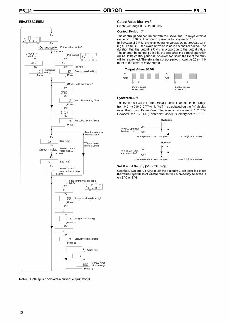
E5AJ/E5BJ/E5EJ
Output valuePress a
o
(Output value display)
20
Press a
cp
1.0
Press a
hys
0
Press a
sp0
Press a
sP1
Press a
ct
0.0
Press a
hb
8.0
Press a
p
233
Press a
i
40
Press a
d
50.0
Press a
ofr
ON/OFFcontrol
(Hysteresissetting)
PID control
(Control period setting)
(Models with event input)
(Set point 0 setting SP0)
(Set point 1 setting SP1)
If control output iscurrent output.
(Heater currentvalue display)
(Heater burnoutalarm value setting)
If the control mode is set to2-PID
(Proportional band setting)
(Integral time setting)
(Derivative time setting)
(Manual resetvalue setting)
SV
PV
SV
PV
SV
PV
SV
PV
SV
PV
SV
PV
SV
PV
SV
PV
SV
PV
SV
PV
SV
PV
0
Current value
(see note)
When I = 0
1 2 3 4ON
1 2 3 4ON
1 2 3 4ON
(See note)Without heaterburnout alarm
(See note)
Note: Nothing is displayed in current output model.
Output V alue Display: oDisplayed range 0.0% to 100.0%
Control Period: cp
The control period can be set with the Down and Up Keys within arange of 1 to 99 s. The control period is factory-set to 20 s.In the case of 2-PID, the relay output or voltage output repeats turn-ing ON and OFF, the cycle of which is called a control period. Theduration that the output is ON is in proportion to the output value.The shorter the control period is, the smoother the control operationwill be. If the control period is, however, too short, the life of the relaywill be shortened. Therefore the control period should be 20 s mini-mum in the case of relay output.
ON
OFF
Control period:10 seconds
ON
OFF
Control period:20 seconds
Output Value: 50.0%
Hysteresis: hys
The hysteresis value for the ON/OFF control can be set in a rangefrom 0.0° to 999.9°C/°F while “hys ” is displayed on the PV displayusing the Up and Down Keys. The value is factory-set to 1.0°C/°F.However, the E5J-F (Fahrenheit Model) is factory-set to 1.8 °F.
Low temperature set point High temperature
Hysteresis
ON
OFFReverse operation(heating control)
Hysteresis
ON
OFF
Normal operation(cooling control)
Low temperature set point High temperature
Set Point 0 Setting ( °C or °F): sp0Use the Down and Up Keys to set the set point 0. It is possible to setthe value regardless of whether the set value presently selected ison SP0 or SP1.

E5J E5J
13
Set Point 1 Setting: sp1
Use the Down and Up Keys to set the set point 1. It is possible to setthe value regardless of whether the set value presently selected ison SP0 or SP1.
14
13
14
13
Contact Input No-contact Input(Open Collector)
ON: The resistance is 1 kΩmax. when short-circui-ted.
OFF: The resistance is100 kΩ min. whenopened.
E5CJ
The set point can be selected by opening or short-circuiting theEV1 terminals (terminals 13 and 14).
ON: The residual voltage is3 V min.
OFF: The current leakage is1 mA max.
Open
Set point 0 (SP0) Set point 1 (SP1)
Closed
20
17
20
17
Contact Input No-contact Input(Open Collector)
E5AJ/E5BJ/E5EJ
The set point can be selected by opening or short-circuitingthe EV1 terminals (terminals 17 and 20). In the case of theE5BJ, however, the terminals 16 and 17 of which should beopened or short-circuited instead.
17
16
17
16
E5BJ E5AJ/E5EJ E5BJ E5AJ/E5EJ
ON: The resistance is 1 kΩmax. when short-circui-ted.
OFF: The resistance is100 kΩ min. whenopened.
ON: The residual voltage is3 V max.
OFF: The current leakage is1 mA max.
E5BJE5AJE5EJ
or
Set point 0 (SP0)
E5BJE5AJE5EJ
or
Set point 1 (SP1)
or or
Heater Current V alue Display: ctThe display range is 0.0 to 55.0 A. FFFF will be displayed if the cur-rent exceeds 55.0 A. When the control output is ON, the currentflowing to the heater is measured and displayed. If the control outputis, however, turned ON for less than 190 ms, the current flow will notbe measured and the current previously measured will be dis-played.
Heater Burnout Alarm V alue Setting: hbThe current value to detect heater burnout can be set within a rangeof 0.0 to 50.0 A.The current value is factory-set to 0.0 A. Check the normal heatercurrent and the current at the time of heater burnout from the heatercurrent value display, and set the set value to the mean value of thecurrent values (i.e., set value = (normal current value + heater burn-out current) 2).If the difference between the normal heater current and heater burn-out current is small, heater burnout detection will not be stable. Forstable detection, the difference in current must be 1.0 A minimum ifthe heater input is less than 10.0 A and 2.5 A minimum if the heaterinput is 10.0 A or more.
Note: 1. Do not allow a current exceeding 50 A to flow in the CT;the maximum continuous heater current is 50 A.
2. Set the value to 0.0 A if the heater burnout alarm is notused, in which case the alarm will not function at all.
Connected to Temperature Controller.
Connected to heater.
Current Transformer Connections

E5J E5J
14
Heater+
–
200 VAC
14
13
12
11
7
6
9
8
105
4
1
3
2
Hea
ter
burn
out a
ndte
mpe
ratu
re a
larm
Alarm output 1
Control output
E5CJ-H
Note: 1. Alarm 1 is used as heater burnout alarm and temperature alarmfor models incorporating a heater burnout alarm.
2. Wire through the hole of the Current Transformer. The CurrentTransformer and the Temperature Controller can be connectedregardless of polarity.
(see note 2)
(see note 1)
E5CJ-H
E5EJ-H
Heater+
–
200 VAC
24
23
22
21
12
11
14
13
15
E5EJ-H
17
16
19
18
20
26
25
28
27
29
5
4
1
3
2
7
6
9
8
10
Alarm output 1
Hea
ter
burn
out a
ndte
mpe
ratu
re a
larm
(see note 1)
(see note 2)
Control output
CT
• Set the alarm mode selector 1 to 0 (i.e., no alarm function is ON)so that alarm output 1 will output only heater burnout alarms.
• If the difference in current is small, increase the apparentelectrical current by increasing the number of turns of the heaterwire around the CT. The current displayed by the heater currentvalue display increases in proportion to the number of turns ofthe heater wire.
• Use the K2CU-FA-GS (incorporating gate input terminals)for detecting three-phase heater burnout.
Output Retention ResetOnce the heater burnout alarm detects heater burnout, alarm output1 will turn ON. To turn OFF alarm output 1, set the heater burnoutalarm value to 0.0 A or turn off the Temperature Controller and thenturn on the Temperature Controller.

E5J E5J
15
• If the control mode is 2-PID with fuzzy self-tuning, theparameters p, i, d, or ofr will not be displayed (i.e., there is noneed to set these parameters). Fuzzy self-tuning always adjustsall PID constants to optimum values inside the TemperatureController.
Proportional Band: pWhen the character “p ” is displayed on the PV display, the propor-tional band (P constant) can be changed using the Up and DownKeys. The new value will be displayed on the SV display. It can beset in a range from 0.1° to 999.9°C/°F in units of 0.1°C/°F. The valueis factory-set to 8.0°C/°F. However, the E5J-F (Fahrenheit Model)is factory-set to 14.4 °F.
Integral T ime : iWhen the character “i ” is displayed on the PV display, the integraltime (I constant) can be changed using the Up and Down Keys. Itcan be set in a range from 0 to 3,999 seconds in units of 1 second.The value is factory-set to 233 seconds.
Derivative T ime : dWhen the character “d ” is displayed on the PV display, the deriva-tive time (D constant) can be changed using the Up and Down Keys.It can be set in a range from 0 to 3,999 seconds in units of 1 second.The value is factory-set to 40 seconds.
Manual Reset V alue Setting (%) : ofrThe necessary output value in stable state will be set within a rangeof 0.0% to 100.0%. The output value is factory-set to 50.0%. In P orPD mode (i.e., when I is 0), the Temperature Controller will be bal-anced with a deviation value between the set point and process val-ue. This deviation value is called the offset. By changing the manualreset value, the offset can be eliminated.
Engineering Level Parameters
The value set before shippingappears. (see note 1)
Displayed if the E5J with a com-munications function is used.
(Data bit length setting)
(Parity check setting)
(Stop bit length setting)
Displayed if the E5J is in 2-PID opera-tion with fuzzy self-tuning.
(Stable range setting)
Displayed if the E5J is in 2-PID opera-tion.
(Alpha setting)
(Automatic return of display mode)
Displayed if the E5J with an alarmfunction is used (see note 2).
(Standby sequencereset method setting)
(Input shift display selection)
Displayed if the E5J with an alarmfunction is used (see note 2).
(Alarm 1 hysteresissetting)
Displayed if the E5J with an alarmfunction is used (see note 2).(Alarm 2 hysteresissetting)
(Set point lower limit setting)
(Set point upper limit setting)
Displayed if the E5J withevent input 2 is used.
(Event input 2 functionselection)
Note: 1. The E5J--F values set before shippingare different. Refer to the E5J Operation Manu-al (Z103).
2. The value will not be displayed if the alarm modeswitch is set to 0 or if the E5J does not incorpo-rate any alarm.
(°C/°F selection)
15.0

E5J E5J
16
d-u °C/°F SelectionTo change the temperature display unit from °C to °F, press the UpKey so that f will be displayed in the set value display.
c: °Cf: °F
SV SV
E5J with Communications FunctionThe communications specifications of the E5J are as follows:
• Data bit length: ASCII 7- (set before shipping) or 8-bit code
• Parity check: None, even (set before shipping), or odd
• Stop bit length: 1 or 2 (set before shipping)
• Use the following parameters to change the above setting.
len Data Bit LengthUse this parameter to change the communications data bit length.
prty Parity CheckUse this parameter to change the communications parity check.
none : NoneeUen : evenodd : odd
SV SV SV
sbit Stop BitUse this parameter to change the stop bit length.
s.tb Stable Range ( °C/°F)This parameter is used to decide conditions under which fuzzy self-tuning operates and can be set within a range of 0.1 to 999.9. If the absolutevalue of the deviation (the difference between the process value and set point) is within the stable range, temperature control operation isdeemed smooth and fuzzy self-tuning will not start.
Set pointStablerange
Stable
PID before tuning PID after tuning
Fuzzy self-tuning
It is deemed that the characteristicsof the control device have beenchanged so that the response wa-veform is processed to tune the PIDconstants.
alfa (α) PID Control TypeBy adjusting internal parameter α of 2-PID within a range of 0.00 to 1.00, PID control such as derivative preceding PID or proportional 2-PID(I-PD) control will be possible.
Set point
α = 0.00 (Derivative preceding PID)
α = 1.00 (Proportional preceding PID)
Difference in set point response due to α.
α = 0.65
To increase the set point response speed, decrease the value of parameter α. If the value of parameter α is decreased, however, the overshoot-ing value will increase.
ret Automatic Return of Display Mode (Return T ime)By setting automatic return of display mode, the display will return to the normal operation display (on level 0 displaying the process value or setpoint) if no key is operated for the time set with this parameter. The return time can be set within a range of 0 to 99 s. If the return time is set to 0 s,this function will not work. The return time is set to 0 s before shipping.

E5J E5J
17
rest Standby Sequence Reset MethodIt is possible to select the restart conditions of the standby sequenceof the alarm attached with standby sequence. If this parameter is setto 0, the standby sequence will restart when the set point, alarm val-ue, or input shift value is changed or the moment the E5J startsoperating including the moment the E5J is turned on. If this pa-rameter is set to 1, the standby sequence will restart only the mo-ment the E5J is turned on. The following timing chart is an exam-ple of a lower limit alarm attached with standby sequence.
Standby sequence releasing point
Standbysequence restart
Standbysequencereleasing point
OFF point due toalarm hysteresis
Alarm point
(Standby sequence reset method 0)
(Standby sequence reset method 1)
Alarm output
Set valuechange
Alarm output
ins Input Shift DisplayIt is possible to select to display or not to display the input shift func-tion on display level 1 with this parameter.
off : Not displayedon : Displayed
SV SV
alh1 Alarm 1 Hysteresis and alh2 Alarm 2 HysteresisIt is possible to adjust alarm sensitivity with both these parameterswithin a range of 0.1 to 999.9. Change the alarm sensitivity of theE5J if the alarm output chatters.
ON
OFF
ON
OFF
Upper limit alarm
Hysteresis
Lower limit alarm
Hysteresis
Low temperature Alarm point
High temperature
Low temperature Alarm point
High temperature
The alarm output will be OFF when the process value is within thealarm hysteresis range when the E5J restarts (e.g., when theE5J is turned on).
sl-l Set Point Lower Limit V alue (°C/°F) and slh Set PointUpper Limit V alue (°C/°F)It is possible to limit the set point changeable range with both theseparameters. For example, if the set point lower limit value is set to0°C and the set point upper limit value is set to 400°C, the set pointcan be changed only between 0°C and 400°C.
eu-2 Event Input 2 T ype SelectionIt is possible to select the function of event input 2. If 0 (set point val-ue selection) is selected, sp-2 and sp-3 will be displayed on displaylevel 1 and if 1 is selected RUN/STOP will be selected. When 0 isselected, the set point can be selected from the following.
20
19
17
EV1
EV2
COM
EV1 EV2 Set point to be selected
Open Open SP0
Short-circuit Open SP1
Open Short-circuit SP2
Short-circuit Short-circuit SP3

E5J E5J
18
Starting Control OperationThe E5J will start control operations as soon as power is turned onuntil power is turned off. Turn off the power and then turn it back onafter setting the desired parameters.
By short-circuiting the EV2 terminals (terminals 17 and 19) of theE5AJ/E5EJ incorporating event input, control operation can be in-terrupted.
Note: Always turn on the Controller and the load simultaneously.Never turn on the load when the Controller is already turnedon. Doing so will disable proper self-tuning and optimumcontrol.For example, when setting the parameters to the Controllerwith the load turned off, turn off the Controller once aftercompleting the setting and then turn it on again simulta-neously with the load. Or, switch event input 2 from STOP toRUN.
Open Short-circuit
Operation Operation is beinginterrupted.
19 19
17 17
Error MessagesThe Temperature controller is provided with self-diagnostic functions, and will display an error message on the PV display when an error isdetected.
Message Error Error output status Item to be checked
Control output Alarm output
s.err (S.Err) Input error OFF (2 mA max.) Processes theerror as anabnormally hightemperature error.
1. Check if the input is outside the possiblecontrol range (i.e., ±10% of the settemperature range) (see note).
2. Check if the settings of the inputs arewrong.
3. Check if there is any wiring mistake,wire burnout, or short-circuit.
e111 (E111) Memory error OFF (2 mA max.) OFF Turn off and then turn on theTemperature Controller. If the displaydoes not change then, repairs arenecessary.
e333 (E333) A/D converter error OFF (2 mA max.) OFF
necessary.If the display returns to normal, theTemperature Controller may have beeninfluenced by noise. Check if noise isbeing generated.
a.err (A.Err) Calibration data error (displayedfor 3 s when the TemperatureController is turned on)
Normal operation (accuracy notguaranteed)
Re-calibration is necessary.
Note: When the input is within the possible control range but outside the possible display range (i.e., –1999 to 9999), will be displayed ifthe value is smaller than –1999 and will be displayed if the value is larger than 9999, however, the control and alarm outputfunctions of the Temperature Controller will work normally.

E5J E5J
19
Fuzzy Self-tuningFuzzy self-tuning is a function that enables the E5J to calculatethe most suitable PID constants for the controlled object.
FeaturesThe E5J judges by itself when to perform fuzzy self-tuning.
Fuzzy Self-tuning FunctionThe fuzzy self-tuning function has three modes.
In SRT (step response tuning) mode, the PID constants are tunedusing a step response method at the time the set point is changed.
In DT (disturbance tuning) mode, the PID constants are amendedso that the controlled temperature will be within the target rangeset in advance when there is external disturbance.
In HT (hunting tuning) mode, when hunting occurs, the PIDconstants are amended to suppress the hunting.
Note: Be sure to turn on the power supply to the load either beforeor simultaneously with the start of Temperature Controlleroperation.Dead time will be measured from the time the TemperatureController starts operating. If a load such as a heater isturned on after the Temperature Controller is turned on,dead time longer than the actual value will be measuredand inappropriate PID constants will be obtained. If an ex-tremely large amount of dead time is measured, the controlamount will be set to 0% for a short period of time beforebeing returned to 100%, and the constants will then be re-tuned. Retuning is performed only for large amounts ofdead time, so be sure to follow the precaution given abovewhen starting operation.
Startup Conditions of SRTSRT will start if the following conditions are satisfied simultaneouslywhen the E5J is turned on or the set point is changed.
At the time the E5 J startsoperating
At the time set point ischanged
1. The set point at the time theE5J starts operating isdifferent from the set pointused at the time SRT waslast executed (see note).
2. The difference between theset point and the processvalue at the time the E5Jstarts operating is largerthan the present proportion-al band value (P) x 1.27+4.
3. The process value at thetime the E5J starts oper-ating is smaller than the setpoint in reverse operationand larger than the set pointin normal operation.
1. The new set point is differ-ent from the set point usedat the time SRT was lastexecuted (see note).
2. The set point changingrange is larger than thepresent proportional bandvalue (P) x 1.27+4.
3. The process value is instable condition before theset point is changed.
4. A larger set point value isset in reverse operation anda smaller set point is set innormal operation.
Note: The last SRT-executed set point is set to 0 before shippingand when changing from 2-PID control to 2-PID control withfuzzy self-tuning.
Imposition Completion Condition of Step Control AmountIn order to prevent overshooting, the step controlled amount mustbe imposed continuously only while the present deviation is thesame as or greater than the value obtained from the proportionalband (P) x 1.27. The step control will not be applied when the devi-ation becomes smaller than this value.
PID Constant Refreshing ConditionsIf the step control amount is applied before the maximum tempera-ture slope (R) is obtained, SRT will not renew any PID constant. Ifthe proportional band obtained from the R and L values that weremeasured before the imposition had been completed is larger thanthe present proportional band, the PID constants will be renewedbecause the measured value is in the direction towards the suitableproportional band value, and the set point at that time will be theSRT-executed set point.
TemperatureSlope (R)
Completion of SRT
Stable range
Time
SPP x 1.27
Stable Temperature StatusIf the temperature is within the stable range for a certain time, it isdeemed that the temperature is stable. This time is called stabilityjudgement time. Like PID constants, stability judgement time is ad-justed with fuzzy self-tuning according to the characteristics of theobject to be controlled. Fuzzy self-tuning will not be activated if thetemperature is stable because the Temperature Controller deemsthat temperature control is smooth.
Shorter than the stability judgement time
Setpoint
Stablerange
Stablerange
(Set to15.0Cbeforeshipping)
Stability judgement time
Stable Stable
Balanced StatusIf the process value is within the stable range for 60 s when there isno output, it is deemed that the the temperature is balanced.
Startup Conditions of DT1. DT will start if the temperature that has been stable varies due
to external disturbance and the deflection of the temperatureexceeds the stable range, and then the temperaturebecomes stable, provided that the number of maximumtemperature values is less than four.
2. DT will start if the set point is changed under the condition thatSRT does not start and the temperature becomes stable,provided that the number of maximum temperature values isless than four.If there are four or more maximum temperature values, HTwill start.
SP
Temperature
Extreme value 2Set point change
Time
Extreme value 1

E5J E5J
20
Startup Conditions of HTHT will be ON when there is hunting with four or more maximumtemperature values (extreme values) while SRT is not beingexecuted.
Extreme value 2 Extreme value 4
Extremevalue 1
Extremevalue 3
Temperature
Time
SP
Note: In specific applications where temperature varies periodi-cally due to disturbance, internal parameters need to be ad-justed. For details, refer to E5J Operation Manual.
Auto-tuningStarting Auto-tuningAuto-tuning can be started by using the following procedure. Usethis procedure when appropriate results are not achieved via fuzzyself-tuning.
1. Turn ON pin 3 of the function selector switch to select the2-PID control mode (refer to page 8).
2. Press the Level Key and the Display Key simultaneously for1 s or longer to start auto-tuning.
Conditions that Prevent Auto-tuningYou will not be able to start auto-tuning when any of the followingconditions exist.
• When the control mode is set for ON/OFF control or 2-PIDcontrol with fuzzy self-tuning.
• When an engineering level parameter is displayed.
• When the key protection switch is set to SP or ALL.
• When the remote/local setting is set to remote.
• When the RUN/STOP setting is set to STOP.
• When a sensor error, memory error, or A/D converter error hasoccurred.
Force-ending Auto-tuningAuto-tuning will be forced to end for any of the following conditions.
• When the Temperature Controller is turned off.
• When the RUN/STOP setting is changed to STOP.
• When a sensor error occurs.
• When the Level Key and the Display Key are pressedsimultaneously for 1 s or longer.
Changing Parameters during Auto-tuning• Parameters cannot be changed during auto-tuning, but the
remote/local setting can be changed.
• The SP also cannot be changed via the event input duringauto-tuning, but the event input status can be changed and theSP will be changed after auto-tuning has been completed.
Set point
Auto-tuning
Auto-tuning started.
Scale changes disabled here.
Event inputterminal
OpenSP0 selected.
ShortedSP1 selected.
SP0
SP1

E5J E5J
21
DimensionsNote: All units are in millimeters unless otherwise indicated.
E5AJ
112
12 98
E5BJ
88
12 98
E5CJ1009.5
58
96 x 96 91 x 91
72 x 72 67 x 67
48 x 4844.8 x 44.8
E5EJ
96
48
112
12 9844
91

E5J E5J
22
Terminal Covers
E53-COV02
E53-COV04
E53-COV03
112
12 115
E5AJ with T erminal Cover
1159.5
58
E5CJ with T erminal Cover
E5EJ with T erminal Cover
112
12 115

E5J E5J
23
Panel CutoutE5AJ
L
120 min.
92+0.8 0
92+0.8 0
92+0.8 0
Side-by-side Mountingof N Controllers
L = (96N – 3.5)+1 0
Side-by-side Mountingof N Controllers
L = (72N – 3.5)+1 0
E5BJ
100 min.L
68+0.7 0
68+0.7 0
68+0.7 0
60 min.
L
45+0.6 0
E5CJ
Side-by-side Mountingof N Controllers
Side-by-side Mountingof N Controllers
E5EJ
120 min.
L
92+0.8 0
45+0.6 0
45+0.6 0
45+0.6 0
92+0.8 0
L = (48N – 2.5)+1 0
Note: 1. Recommended panel thickness is 1 to 4 mm forthe E5CJ and 1 to 8 mm for the E5AJ, E5BJ, andE5EJ.
2. Close side-by-side mounting is possible (in ahorizontal direction).
L = (48N – 2.5)+1 0

E5J E5J
24
InstallationNote: No event input is insulated from the voltage or current output.
100 to 240 VAC 50 or 60 Hz or 24 VAC 50 or 60 Hz 24 VDC
100 to 240 VAC 50 or 60 Hz or 24 VAC 50 or 60 Hz 24 VDC
100 to 240 VAC 50 or 60 Hz or 24 VAC 50 or 60 Hz 24 VDC
Event 2
Use these terminalswhen connecting athermocouple.
12 VDC 40 mA24 VDC 20 mA4 to 20 mA
10
9
8
7
6
5
4
3
2
1
29
28
27
26
25
24
23
22
21
–
+
+
–
8
7
8
7
8
7
Control output
Alarm output 2
For relayoutput
For voltageoutput
For linearoutput
+
–
*Alarm output 1
13
12
11 B
B
A
20
19
18
17
16
15
14
13
12
11
CT
29
28
27
26
25
RD
SG
SD
SG
RS-232C
29
28
27
26
25
RDB
RDA
SG
SDA
SDB
RS-422
29
28
27
26
25
SG
RS-485
Use these terminals whenconnecting a platinum resistance thermometer.
* A model with communicationsfunction has no event input.
Event 1*
E5AJ/E5EJ
E5BJ
Event 1*
Control output
Use these terminalswhen connecting athermocouple.
6
5
4
3
2
1
18
17
16
15
14
13
–
+
Alarmoutput1*
9
8
7 B
B
12
11
10
9
8
7
CTUse these terminals when connecting aplatinum resistance thermometer.
+
–
12
11
12
11
12
11
For relayoutput
For voltageoutput
For linearoutput
+
–
Alarm output 2
A
E5CJ-2B Standard Models
12 VDC 20 mA 4 to 20 mA
+
–
10
9
10
9
10
9
For relayoutput
For voltageoutput
For linearoutput
+
–Control output
Use these terminalswhen connecting athermocouple.
5
4
3
1
14
13
12
11
–
+
Alarmoutput 1*
8
7
6 B
B
10
9
8
7
6Alarm output 2
Event 1*
CT
A
Use these terminals when connecting aplatinum resistance thermometer.
2
B()
A()
A()
B()
+
+
+
+
–
–
–
SOURCE
12 VDC 40 mA24 VDC 20 mASOURCE
SOURCE
4 to 20 mA

E5J E5J
25
100 to 240 VAC 50 or 60 Hz or 24 VAC 50 or 60 Hz 24 VDC
100 to 240 VAC 50 or 60 Hz or 24 VAC 50 or 60 Hz 24 VDC 12 VDC 20 mA 4 to 20 mA
+
–
10
9
10
9
10
9
For relayoutput
For voltageoutput
For linearoutput
+
–Control output
Use these terminalswhen connecting athermocouple.
5
4
3
1
14
13
12
11
–
+
Alarmoutput 1
8
7
6 B
B
10
9
8
7
6Alarm output 2
A
Use these terminals when con-necting a platinum resistancethermometer.2
12 VDC 20 mA 4 to 20 mA
+
–
10
9
10
9
10
9
For relayoutput
For voltageoutput
For linearoutput
+
–Control output
Use these terminalswhen connecting athermocouple.
5
4
3
2
1
14
13
12
11
–
+
8
7
6 B
B
10
9
8
7
6
A
Use these terminals when con-necting a platinum resistancethermometer.
E5CJ-2 Simple Models
E5CJ- Simple Models
SOURCE
SOURCE
Note: Always turn on the Controller and the load simultaneously. Never turn on the load when the Controller is already turned on. Doing so willdisable proper self-tuning and optimum control.For example, when setting the parameters to the Controller with the load turned off, turn off the Controller once after completing thesetting and then turn it on again simultaneously with the load. Or, switch event input 2 from STOP to RUN.
* The alarm output 1 and heater burnout alarm are integrated into one general alarm.
* The event input is not electrically isolated from the voltage output or current output.

E5J E5J
26
PrecautionsMountingThe dimensions of the Temperature Controller conform toDIN 43700. Recommended panel thickness is 1 to 8 mm for theE5AJ, E5BJ, and E5EJ, and 1 to 4 mm for the E5CJ.
The mounted Temperature Controller must be horizontally level.
Do not install the Temperature Controller in a location exposed toexcessive dust or corrosive gases. Moreover, avoid locations sub-ject to heavy vibration or shock, water or oil spray, or high tempera-tures. Any of these conditions will affect product life.
Isolate the Temperature Controller from equipment that generatesstrong, high-frequency noises such as high-frequency welders, be-cause such equipment may prevent proper operation.
E5AJ/E5BJ/E5EJTwo mounting brackets are provided with the Temperature Control-ler. Mount one of the brackets to the top and the other one to the bot-tom of the Temperature Controller. Turn the ratchets of the mountingbrackets clockwise with a Phillips screwdriver until they snap.Insert the unit back into the case by pushing the unit until it clicks intoplace.
E5CJInsert the Temperature Controller into the square hole of the paneland insert an adapter from the backside so that there will be nospace between the Temperature Controller and the panel. Then se-cure the Temperature Controller with a screw.
Tightening screw
DismountingLoosen the screw of the adapter for dismounting.
Connection ExampleWith Solderless T erminalUse M3.5 x 8 solderless terminals with the Temperature Controller’sM3.5 self-rising pressure plate screws.
Solder-dipped LeadsStrip 6 to 8 mm of the lead wires and carefully arrange the wire tips.
Do not tighten the terminal screw with excessive force, because do-ing so many damage them. The terminal block of the TemperatureController is constructed so that the lead wires can be connected toall the terminals from the same direction.
Example: E5CJ
Input Type ConnectionTo reduce inductive noise influence, the lead wires connecting theinput type to the Temperature Controller must be separated from thepower lines and load lines.
Use the specified compensating conductors for thermocouples.Use lead wires having a small resistance for platinum resistancethermometers.
Sequenced CircuitsSeveral seconds are required until the relay is turned ON after pow-er has been supplied to the Temperature Controller. Therefore, takethis time delay into consideration when designing sequenced cir-cuits which incorporate a Temperature Controller.

E5J E5J
27
Watertight Cover• Four sizes (96 x 96, 72 x 72, 48 x 96, 48 x 48) are available.
• Conforms to IP66 or NEMA4 (indoors).
Ordering InformationSize 96 x 96 mm 72 x 72 mm 48 x 96 mm 48 x 48
Model Y92A-96N Y92A-72N Y92A-49N Y92A-48N
MaterialsFront cover 94V-2 polycarbonate
Packing Chloroprene rubber
Panel SUS304
Nomenclature
Note: Tighten the knurled screw to a torque of 0.03 N m (3 kgf cm)and the hexagonal nut to a torque of 0.05 N m (5 kgf cm).
48 x 48 mm 96 x 96/72 x 72/48 x 96 mm
PanelFlat washer
Knurled screw
PanelFixture
Spring lock washer
Hexagonal nut
Knurled screw
Dimensions
Y92A-48N (48 x 48 mm) Y92A-49N (48 x 96 mm)
29.4
21.9(2)
131.7
67.6
69
12
(2)
21.9 14
87.7
67.6
79.2

E5J E5J
28
Y92A-72N (72 x 72 mm) Y92A-96N (96 x 96 mm)
Panel Cutout
Y92A-48N (48 x 48 mm)
(2)21.9
29.4
131.7
115.6
107.7
91.6
21.9(2)
29.4
Two, 4.5 dia.
69±0.3 45+0.6 0
Squarehole
45+0.6 0
PrecautionsIt is possible to open or close the front cover by untightening or tight-ening the knurled screw.
Be sure to take the space required for the opening and closing of thefront cover into consideration when installing the Watertight Cover.
The front cover is made of polycarbonbate, which can be cleanedusing water, methanol, or ethanol.
Regularly check the packing, the quality of which will deteriorateover the process of time.
The front cover can be mounted in any direction.

E5J E5J
29
SSRConnection Example of Temperature Controller and SSR
+
–
+
–
Temperature Controller
Voltage outputterminal (for driv-ing SSR)
Connectable
Load
HeaterPower supplyfor load
Power SSR
SSR
E5AJ/E5BJ/E5EJ
Temperature Controllerwith Voltage Output(12 VDC, 40 mA max.)
See the following table.
E5CJ
Temperature Controllerwith Voltage Output(12 VDC, 20 mA max.)
INPUT LOAD
Model G3PA-VD
240 V: 10 A, 20 A, 40 A, 60 A480 V: 20 A, 30 A
G3NH
75 A, 150 A
G3NA
240 V: 5 A, 10 A, 20 A, 40 A480 V: 10 A, 20 A, 40 A
G3NE
5 A, 10 A, 20 A
G3B
5 A
Appearance
SSRsconnected inparallel
E5AJ/BJ/EJ: 5 pcs. (8 pcs.)E5CJ: 3 pcs. (4 pcs.) (see note)
E5AJ/BJ/EJ: 8 pcs.
E5CJ: 4 pcs.
E5AJ/BJ/EJ: 6 pcs.E5CJ: 3 pcs.
E5AJ/BJ/EJ: 2 pcs.
E5CJ: 1 piece
E5AJ/BJ/EJ: 5 pcs.
E5CJ: 2 pcs.
Rated inputvoltage
5 to 24 VDC 5 to 24 VDC 5 to 24 VDC 12 VDC 5 to 24 VDC
Features Thin, monoblockconstruction with heat sink
For high-powerheater control
Standard model with screwterminals
Compact, low-costmodel with tabterminals
Socket, modelwith 5-Aswitchingcapacity
Note: The number of Units in parentheses is for the 400-V type.
OMRON CorporationSupervisory Control Devices Division28th Fl., Crystal Tower Bldg.,1-2-27, Shiromi, Chuo-ku,Osaka 540-6028 JapanPhone: (81)6-6949-6035 Fax: (81)6-6949-6069
ALL DIMENSIONS SHOWN ARE IN MILLIMETERS.To convert millimeters into inches, multiply by 0.03937. To convert grams into ounces, multiply by 0.03527.
Cat. No. H062-E1-5A In the interest of product improvement, specifications are subject to change without notice.
Printed in Japan0299-2M (1093) a