temperature controller operation manual series user manual.pdf · 4 4.2 level 2 (pid level) press...
TRANSCRIPT

TEMPERATURE CONTROLLER
OPERATION MANUAL
TB100 TB400 TB700 TB600 TB900

1
Before using please check whether range , input and output match your requirement.
1. Front panel instruction 1.1 DISPLAY
PV:Process value,4 digit display (red color) SV:Setting value,4 digit display (green color)
1.2 LED OUT1 :Output 1,green color OUT2 :Output 2,green color AT :Auto Tuning,yellow color PRO :Program ,yellow color --- Only available for PTB models.
AL1 :Alarm 1,red color AL2 :Alarm 2,red color MAN :Manual,yellow color
1.3 KEY SET :MODE & SET key
:SHIFT key :DOWN key :UP key
A/M :Auto/Manual key
2 Auto tuning 2.2 Once AT set YES,auto tuning is to be performed. 2.3 After auto tuning finished,PID parameter is to be set
auomatically. 2.4 ATVL=auto tuning offset,and it will be deduced from SV
(it can prevent over shoot during auto tuning) SV-ATVL=Auto-tuning value,ATVL=auto tuning offset Ex.SV=200℃,ATVL=5,Auto tuning point is at 195℃
* ATVL means Auto-tuning point in program type
2.5 Auto tuning failure Passible 1: ATVL is too big. (If not sure,set ATVL=0)
Passible 2: System time is too long.(Set PID parameter individually)

2
3. Error information
DISPLAY DESCRIPTION
IN1E Open circuit of main control sensor. **** ADCF A/D converter failed. **** CJCE Cold junction compensation failed.
IN2E Open circuit of sub control sensor. UUU1 PV exceeds USPL. NNN1 PV under LSPL. UUU2 Input signal of sub control exceeds the upper limit. NNN2 Input signal of sub control under the lower limit. **** RAMF RAM failed.
INTF Interface failed. AUTF Auto tuning failed.
NOTE::::If the “*” marked error comes up,the Controller needs repair.
Please send it to the nearest sales office or retail dealer.

3
4. Operating flow 4.1 LEVEL 1 (User Level)
PVSV
Display PVDisplay SV
Output Percentage
Auto Tuning Status
Alarm 1 set
To LEVEL 2(press Set key for 5 sec.)
Alarm 2 set
Alarm 3 set
set
OUTL100
ATYES/NO
AL10
AL20
AL30
set
set
set
set
4.1.1 Press the SHIFT KEY ( ) to change the parameters. If the SHIFT
KEY is pressed,the first digit begins blinking. Press the UP KEY( ) or DOWN KEY( ) to increase or decrease the value of the digit,then press the SHIFT KEY( ) again to go to the next digit. As all the digit are written,press SET KEY to enter the value.
4.1.2 SET KEY also has the function of changing MODEs,if the SET KEY is pressed,the display shows the next MODE.
4.1.3 Press SET KEY for 5 sec. the display goes to LEVEL 2,and do the same thing to return LEVEL 1.
4.1.4 If any key were not pressed for 1 minute,the display would go to LEVEL 1.
4.1.5 Press A/M KEY the display to go to LEVEL 1,no matter where it is. 4.1.6 If OUTL set "0",it means the controller has no output,

4
4.2 LEVEL 2 (PID Level) press SET key for 5 seconds to enter Level 2
P13
SetSetSetSet
I1240
SetSetSetSet
D160
SetSetSetSet
db 10
SetSetSetSet
ATVL0
SetSetSetSet
CYT110
SetSetSetSet
HYS11
SetSetSetSet
P23
SetSetSetSet
I2240
SetSetSetSet
D2240
SetSetSetSet
CYT210
SetSetSetSet
HYS21
SetSetSetSet
GAP10
SetSetSetSet
GAP20
SetSetSetSet
LCK0000
Main ControlProportional Band
Range:0-200%ON/OFF at P=0
Main ControlIntegral Time
Main ControlDerivative Time
Main ControlDead-band Time
Main ControlAuto tuning off-set
Main ControlProportional Cycle
Main ControlHysteresis
Sub ControlProportional Band
Sub ControlIntegral Time
Sub ControlDerivative Time
Sub ControlProportional Cycle
Sub ControlHysteresis
Main ControlGap (Output 1)
Sub ControlGap (Output 2)
Function Lock
Range:0~3600 SecIntegral OFF at I=0
Range:0~900 SecDerivative OFF at D=0
Dead time compensationRange:0~1000 Sec
Range:0~USPL
Output (SSR=1,4 ~ 20mA=0,Relay=over10)Range:0~150 Sec
For ON/OFF control onlyRange:0~1000
Sames as P1
Sames as I1
Sames as D1
Sames as CYT1
Sames as HYS1
For 2 output use only,set the volume turning."OFF" early to SV
For 2 output use only,set the volume turning."ON" early to SV
LCK=0000000000000000,To enter any Level ( not include SET Level) and change their parametersLCK=1111111111111111,To enter any Level (include SET Level) and change their parametersLCK=0100010001000100,To enter Level 1 & 2 and to change their parameters.LCK=0110011001100110,To enter Level 1 & 2 and to change Level 1parameters only.LCK=0001000100010001,To enter Level 1 only and to change SV only.LCK=0101010101010101,it can't change any parameter except LCK.
SetSetSetSet
Return P1

5
4.3 LEVEL 3 (INPUT Level) When LCK=0000,press SET key and SHIFT KEY for 5 seconds to enter LEVEL 3
INP1K2
SetSetSetSet
ANL10
SetSetSetSet
ANH15000
SetSetSetSet
DP0000
SetSetSetSet
LSPL0.0
SetSetSetSet
USPL400.0
SetSetSetSet
ANL20
SetSetSetSet
ANH25000
SetSetSetSet
ALD101
SetSetSetSet
ALT110
SetSetSetSet
ALD201
SetSetSetSet
ALT20
SetSetSetSet
ALD301
SetSetSetSet
ALT30
SetSetSetSet
Main Controlinput selection
select the input range,refer to inputselection (P.12 ~ 13)
Main ControlAnalog Zero set
Main ControlAnalog Span set
Decimal point
Lower set-point limit
Upper set-point limit
Sub ControlAnalog Zero set
Sub ControlAnalog Span set
Alarm mode of AL1
Time set of Alarm 1
Alarm mode of AL2
Time set of Alarm 2
Alarm mode of AL3
Alarm 3 time set
It is used as input code are AN1 to AN5Range:LSPL~USPL
Same as ANL1
To set the position of decimal point
To set the lowest point within INP1
To set the highest point within INP1
It is used as input code are AN1 to AN5Range:LSPL~USPL
Sames as ANL2
Range:00~19 (see P.14~15)
It is used in program functionRange:0~99.59 min. 0=flicker alarm,99.59=continued,and other=on delay time
Range:00~19 (see P.14~15)
Sames as ALT1
Range:00~19 (see P.14~15)
Sames as ALT1
HYSA0
SetSetSetSet
Hysteresis of alarm Range:0~1000
CLO1150
Main Controlcalibration
Calibrate the low value of outputRange:LSPL~USPL(current output only)
SetSetSetSet

6
CHO13500
SetSetSetSet
CLO2150
SetSetSetSet
CHO23200
SetSetSetSet
CLO3
SetSetSetSet
RUCY00
SetSetSetSet
WAIT0
SetSetSetSet
HYSM1
SetSetSetSet
IDNO1
SetSetSetSet
BAUD2400
SetSetSetSet
SVOS0
SetSetSetSet
PVOS0
SetSetSetSet
UNITC
SetSetSetSet
SOFT1000
SetSetSetSet
CASC
SetSetSetSet
Main ControlCalibration high
To calibrate the high value of outputRange:0~9999(current output only)
Sub controlCalibration low
Sub controlCalibration high
Transmitter controlCalibration low
Timer of motor
Use in program forwaiting continuedoperation
Hysteresis for motorcontrol
ID number(don't care)
Baud rate(don't care)
Compensate SV
Compensate PV
Unit of PV & SV
Soft filter(don't care)
don't care
Same as CLO1
Same as CHO1
Same as CLO1
Full run time of proportional motor(without potentiometer) Range:0~150 sec.
0=No WaitOther=Wait volume
Range:0~1000
Communication ID number
UART baud rate selectionRange:110~9600 BIT/sec
Range:-1000~1000
Range:LSPL~USPL
Range:C,F,A(analog)
Adjust the response time of PV(the bigger, the faster)Range:0.05~1.00
OUDHEAT
SetSetSetSet
Action mode Range:heat,cool
OPADPID Control action Range:PID,Fuzzy
HZ60 Frequency Range:50,60HZ
CHO3
SetSetSetSet
Transmitter controlCalibration high
Same as CHO1
SetSetSetSet
SetSetSetSet
Return INP1

7
4.4 LEVEL 4 (SET Level) When LCK=1111,press SET key and SHIFT KEY for 5 seconds to enter Level 4. There are SET 0.1 to SET 9.4 for use. 4.4.1 Display::::
SET 1
0 1 0 1
SET * . 1SET * . 1SET * . 1SET * . 1
SET * . 2SET * . 2SET * . 2SET * . 2
SET * . 3SET * . 3SET * . 3SET * . 3
SET * . 4SET * . 4SET * . 4SET * . 4
Press SET SET SET SET key to changeSET 0.* ~ 9.*
0=lock0=lock0=lock0=lock
1=open1=open1=open1=open
4.4.2 Function of SETs
SET Function SET Function 1.1 OUTL 5.1 CLO2,CHO2 1.2 AT 5.2 CLO3,CHO3 1.3 AL1 5.3 RUCY,WAIT,HYSM1.4 AL2 5.4 IDNO,BAUD 2.1 AL3 6.1 SVOS 2.2 ANL1,ANH1,DP 6.2 PVOS 2.3 LSPL,USPL 6.3 UNIT 2.4 ANL2,ANH2 6.4 SOFT 3.1 ALD1 7.1 CASC 3.2 ALT1 7.2 OUD 3.3 ALD2 7.3 OPAD 3.4 ALT2 7.4 HZ 4.1 ALD3 4.2 ALT3 4.3 HYSA 4.4 CLO1,CHO1

8
SET Function Remarks
0=No repeat 8.1 1=Program repeat 0=No power failure 8.2 1=With power failure 0=Start from 0 8.3 1=Start from PV
Program Use
9.3 TRS SV 9.4 TRS PV
Auxiliary Output Use
0=No Remote SV 0.3 1=Remote SV
! NOTE::::Please don't operate SET 8.4,otherwise the controller's process
will be in confusion. 4.4.3 FUNCTION OF LCK LCK=0000,It can enter Level 3 ( press SET + for 5 sec.) LCK=1111,It can enter Level 4 ( press SET + for 5 sec.) LCK=0100,It can enter Level 1 & 2 and change their parameters. LCK=0110,It can enter Level 1 & 2 but change Level 1 parameters only. LCK=0001,It can enter Level 1 only and change SV only. LCK=0101,It can't change any parameters except LCK.

9
4.5 PROGRAM LEVEL (to be ordered)
PTN1
SetSetSetSet
SEG1
SetSetSetSet
TIMER
SetSetSetSet
SV-1
SetSetSetSet
TM-1
SetSetSetSet
OUT-1100
SetSetSetSet
SV-2
SetSetSetSet
TM-2
SetSetSetSet
OUT-2
SetSetSetSet
SV-3
SetSetSetSet
TM-3
SetSetSetSet
OUT-3
SetSetSetSet
SV-4
SetSetSetSet
TM-4
SetSetSetSet
Set program patternRange:0~2
Program segment displayResprent :("pattern"_"segment")
Program timer displayRange:0~99 hour 59minSet volume for Seg.1Range:LSPL~USPL
Set time for Seg.1Range:0~99 hour 59 min
Set output for Seg.1Range:0~100%If OUT=0,No program function
Set volume for Seg.2
Set time for Seg.2
Set output for Seg.2
Set volume for Seg.3
Set time for Seg.3
Set output for Seg.3
Set volume for Seg.4
Set time for Seg.4
OUT-4 Set output for Seg.4
LEVEL 1SetSetSetSet
SV-5
SetSetSetSet
TM-5
SetSetSetSet
OUT-5
SetSetSetSet
SV-6
SetSetSetSet
TM-6
SetSetSetSet
OUT-6
SetSetSetSet
SV-7
SetSetSetSet
TM-7
SetSetSetSet
OUT-7
SetSetSetSet
SV-8
SetSetSetSet
TM-8
SetSetSetSet
OUT-8
Set volume for Seg.5
Set time for Seg.5
Set output for Seg.5
Set volume for Seg.6
Set time for Seg.6
Set output for Seg.6
Set volume for Seg.7
Set time for Seg.7
Set output for Seg.7
Set volume for Seg.8
Set time for Seg.8
Set output for Seg.8
SetSetSetSet
SetSetSetSet
Return LEVEL 1
10
4.5.1 This program has 2 patterns,each pattern contains 8 segments. The segment can be arranged a period of Ramp status or Soak status.
4.5.2 Terminologies pattern :A program consists of some steps. Step :A Ramp status + a Soak status. Ramp status:The status with changing SV. Ramp status:The status with fixed SV.
4.5.3 Operating 1. "KEY" function(no changing parameter)
(START) :To start program procedure,PRO in panel flicker. (WAIT) :To suspend program procedure,PRO in panel will
stop flicker but light. + SET(JUMP):To to jump segment.
+ SET (RESET):To reset program procedure,PRO in panel will be "off".
2. Alarm Function:::: If ALD1 to be set “07”(*refer to the selection,p.14~15), AL1 to be set “2”(AL1=2,it means alarm in segment 2 end), ALT1 to be set “00.10”(alarm time 10 sec.). ****In this case,when program proceeds to segment 2 end,ALM1 relay will be on 10 sec.
3. END function:::: If ALD to be set “17”(refer to the selection,p.14~15),This program will be end in segment 8 or 16. * In this case,PV and END will flicker in display window and the alarm relay acts. This controller doesn’t have END order if program procedure are less than 8 segments. In this case,please set segment’s out = 0. then this program will be end in last set segment. Otherwise,it will proceed 8 or 16 segments.
4. Linking Function:::: PTN=1 proceed pattern 1,contains 8 segments. PTN=2 proceed pattern 2,contains 8 segments. PTN=0 linking proceed pattern 1 and 2 totally 16 segments.(set PTN1 and PTN2 at first,then set PTN=0)
5. Other function(****refer to LEVEL 4) SET 8.1=1 program repeat. SET 8.2=0 No power fail function.

11
SET 8.2=1 with power fail function (if power suspend,the controller will keep memory)
SET 8.3=0 program start from 0. SET 8.3=1 program start from PV.
12
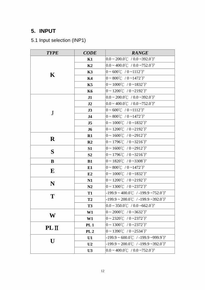
5. INPUT 5.1 Input selection (INP1)
TYPE CODE RANGE K1 0.0 ~ 200.0℃ / 0.0 ~392.0℉ K2 0.0 ~ 400.0℃ / 0.0 ~752.0℉ K3 0 ~ 600℃ / 0 ~1112℉ K4 0 ~ 800℃ / 0 ~1472℉ K5 0 ~ 1000℃ / 0 ~1832℉
K
K6 0 ~ 1200℃ / 0 ~2192℉ J1 0.0 ~ 200.0℃ / 0.0 ~392.0℉ J2 0.0 ~ 400.0℃ / 0.0 ~752.0℉ J3 0 ~ 600℃ / 0 ~1112℉ J4 0 ~ 800℃ / 0 ~1472℉ J5 0 ~ 1000℃ / 0 ~1832℉
J
J6 0 ~ 1200℃ / 0 ~2192℉ R1 0 ~ 1600℃ / 0 ~2912℉
R R2 0 ~ 1796℃ / 0 ~3216℉ S1 0 ~ 1600℃ / 0 ~2912℉
S S2 0 ~ 1796℃ / 0 ~3216℉
B B1 0 ~ 1820℃ / 0 ~3308℉ E1 0 ~ 800℃ / 0 ~1472℉
E E2 0 ~ 1000℃ / 0 ~1832℉ N1 0 ~ 1200℃ / 0 ~2192℉
N N2 0 ~ 1300℃ / 0 ~2372℉ T1 -199.9 ~ 400.0℃ / -199.9 ~752.0℉ T2 -199.9 ~ 200.0℃ / -199.9 ~392.0℉ T
T3 0.0 ~ 350.0℃ / 0.0 ~662.0℉ W1 0 ~ 2000℃ / 0 ~3632℉
W W1 0 ~ 2320℃ / 0 ~2372℉ PL 1 0 ~ 1300℃ / 0 ~2372℉ PLⅡⅡⅡⅡ PL 2 0 ~ 1390℃ / 0 ~2534℉ U1 -199.9 ~ 600.0℃ / -199.9 ~999.9℉ U2 -199.9 ~ 200.0℃ / -199.9 ~392.0℉ U
U3 0.0 ~ 400.0℃ / 0.0 ~752.0℉

13
TYPE CODE RANGE
L1 0 ~ 400℃ / 0 ~752℉ L L2 0 ~ 800℃ / 0 ~1472℉
JP 1 -199.9 ~ 600.0℃ / -199.9 ~999.9℉ JP 2 -199.9 ~ 400.0℃ / -199.9 ~752.0℉ JP 3 -199.9 ~ 200.0℃ / -199.9 ~392.0℉ JP 4 0 ~ 200℃ / 0 ~392℉ JP 5 0 ~ 400℃ / 0 ~752℉
JIS
PT100
JP 6 0 ~ 600℃ / 0 ~1112℉ DP 1 -199.9 ~ 600.0℃ / -199.9 ~999.9℉ DP 2 -199.9 ~ 400.0℃ / -199.9 ~752.0℉ DP 3 -199.9 ~ 200.0℃ / -199.9 ~392.0℉ DP 4 0 ~ 200℃ / 0 ~392℉ DP 5 0 ~ 400℃ / 0 ~752℉
DIN
PT100
DP 6 0 ~ 600℃ / 0 ~1112℉ JP.1 -199.9 ~ 600.0℃ / -199.9 ~999.9℉ JP.2 -199.9 ~ 400.0℃ / -199.9 ~752.0℉ JP.3 -199.9 ~ 200.0℃ / -199.9 ~392.0℉ JP.4 0 ~ 200℃ / 0 ~392℉ JP.5 0 ~ 400℃ / 0 ~752℉
JIS
PT50
JP.6 0 ~ 600℃ / 0 ~1112℉
AN1 AN1 -10 ~ 10mV / -1999~9999 AN2 AN2 0 ~ 10mV / -1999~9999 AN3 AN3 0 ~ 20mV / -1999~9999 AN4 AN4 0 ~ 50mV / -1999~9999 AN5 AN5 10 ~ 50mV / 1999~9999
*The initial set in factory is “K2” without any certain requirement
14
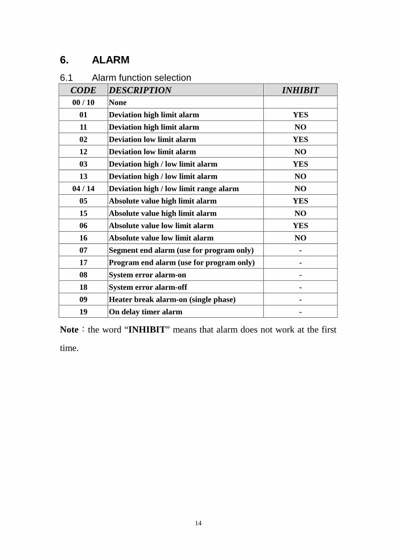
6. ALARM 6.1 Alarm function selection
CODE DESCRIPTION INHIBIT 00 / 10 None
01 Deviation high limit alarm YES 11 Deviation high limit alarm NO 02 Deviation low limit alarm YES 12 Deviation low limit alarm NO 03 Deviation high / low limit alarm YES 13 Deviation high / low limit alarm NO
04 / 14 Deviation high / low limit range alarm NO 05 Absolute value high limit alarm YES 15 Absolute value high limit alarm NO 06 Absolute value low limit alarm YES 16 Absolute value low limit alarm NO 07 Segment end alarm (use for program only) - 17 Program end alarm (use for program only) - 08 System error alarm-on - 18 System error alarm-off - 09 Heater break alarm-on (single phase) - 19 On delay timer alarm -
Note:the word “INHIBIT” means that alarm does not work at the first
time.

15
6.2 Alarm action description
15
05
0414
03
02
0010 Non
01
Deviation high alarm inhibit
HIGHONOFF
LOW
11
Deviation high alarm no inhibit
HIGHONOFF
LOW
Deviation low alarm inhibit
Deviation low alarm no inhibit
HIGHON OFF
LOW
High low alarm inhibit
HIGHON OFF
LOWON
Band alarm
HIGHOFF ON
LOWOFF
Absolute high alarm inhibit
HIGHLOWONOFF
Absolute high alarm no inhibit
HIGHLOWONOFF
16
Absolute low alarm no inhibit
HIGHLOWOFFON
::::SV
::::Alarm set value(inhibit means alarm doesn'twork at the first time)
07
Segment end alarm(use for program only)
(1) ALD1~3,set 07(2) AL1~3=alarm segment No.set(3) ALT1~3 if set 0=flicker alarmALT1~3 if set 99.59=continued alarmALT1~3 if set others=ON delay time
17
Program end alarm(use for program only)
OFF ON
RUN END
08
System error alarm - ON
OFF ON
Normal Error
18
System error alarm - OFF
ON OFF
Normal Error
09
AL
AL
AL
19
On delay timerWhen PV=alarm SV,it keeps acertain period(set time)beforealarm action.Range:00H.00M~99H.59M
Absolute low alarm inhibit
HIGHLOWOFFON06
HIGHON OFF
LOW
12
13
High low alarm no inhibit
HIGHON OFF
LOWON
16
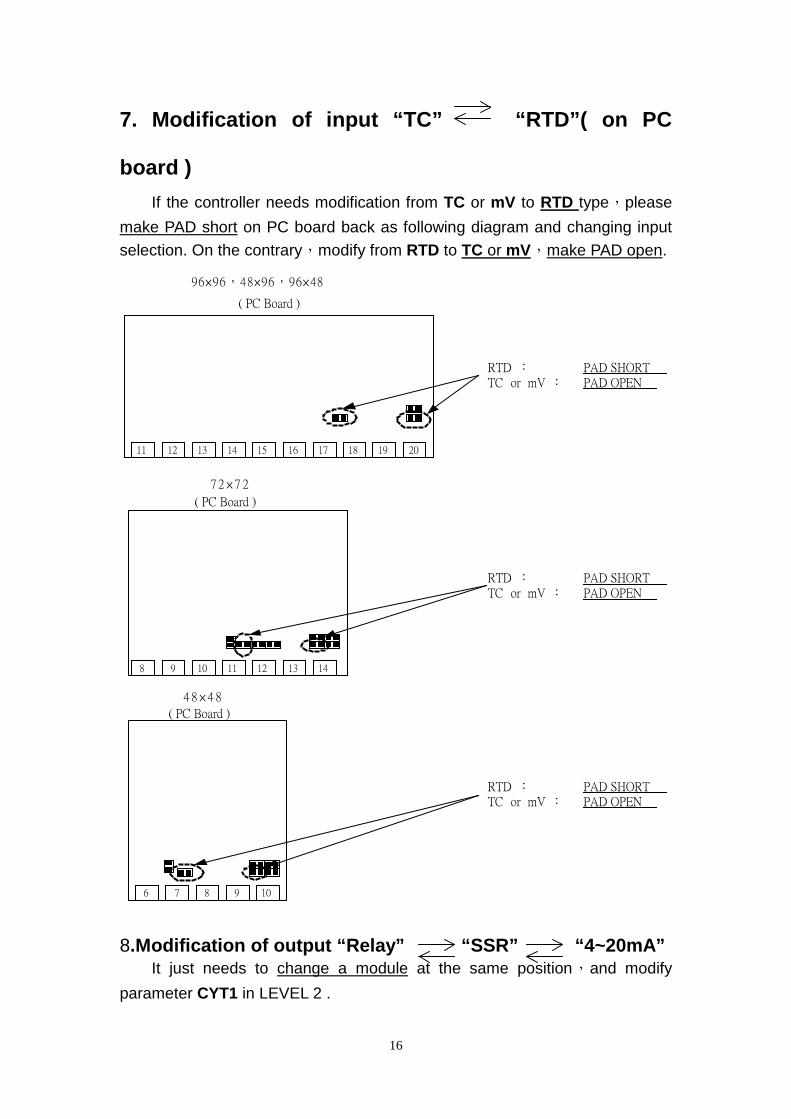
7. Modification of input “TC” “RTD”( on PC
board ) If the controller needs modification from TC or mV to RTD type,please make PAD short on PC board back as following diagram and changing input selection. On the contrary,modify from RTD to TC or mV,make PAD open.
12 13 14 15 16 17 18 19 20
( PC Board )
96×96,48×96,96×48
RTD : PAD SHORTTC or mV : PAD OPEN
8 9 10 11 12 13 14
11
( PC Board )
7 2 × 7 2
RTD : PAD SHORTTC or mV : PAD OPEN
6 7 8 9 10
( PC Board )
4 8 × 4 8
RTD : PAD SHORTTC or mV : PAD OPEN
8.Modification of output “Relay” “SSR” “4~20mA” It just needs to change a module at the same position,and modify parameter CYT1 in LEVEL 2 .

17
9. Modification of output
“HEAT/ALARM” “HEAT/COOL” (on PC board)
12 13 14 15 16 17 18 19 20
( PC Board )
96×96,48×96,96×48
11
PAD AL3:SHORT
PAD OUT2:OPEN
12 13 14 15 16 17 18 19 20
( PC Board )
96×96,48×96,96×48
11
PAD AL3:OPEN
PAD OUT2:SHORT
8 9 10 11 12 13 14
( PC Board )
6 7 8 9 10
( PC Board )
4 8×48
7 2×72
PAD OUT2:OPEN
PAD AL1:SHORT
8 9 10 11 12 13 14
( PC Board )
7 2×72
PAD OUT2:SHORT
PAD AL1:OPEN
PAD OUT2:OPEN
PAD AL1:SHORT
6 7 8 9 10
( PC Board )
48×4 8
PAD OUT2:SHORT
PAD AL1:OPEN
HEAT / ALARM HEAT / COOL

18
10. Modification of INPUT::::0~1V,,,,0~5V,,,,0~10V,,,,mA 10.1 Hardware part:
96×96,,,,48×96,,,,96×48 72×72 48×48 INPUT(+) PIN 17 PIN 11 PIN 7 INPUT (-) PIN 20 PIN 14 PIN 10 1V,,,,5V,,,,10V: (R4 use 100Ω) mA: (R3 use 100Ω,R5 use 2.4Ω, S3&S5 SHORT) 0 ~ 1V: (R1 use 2KΩ,S1&S4 SHORT) 0 ~ 5V: (R2 use 10KΩ,S2&S4 SHORT) 0 ~ 10V: (R3 use 22KΩ,S3&S4 SHORT)
BACKFRONT
19 11
( PC Board )
96×96,48×96,96×48
20
FRONT
14 13 8
( PC Board )
FRONT
10 9 6
( PC Board )
48×48
72×72
19 20
( PC Board )
11
BACK
8 13 14
( PC Board )
BACK
9 10
( PC Board )
48×48
72×72
96×96,48×96,96×48
. . . . . . . . . . . . . . . .
R2
R3
R4
R5
R1
. . . . . . . . . . . .
S1S2 S4S3 S5
R2
R3
R4
R5
R1
. . . .
S1S2 S4S3 S5
. . . .
R2
R3
R1
R4
R5
. . . .
S1S2 S4S3 S5
6 . .
19
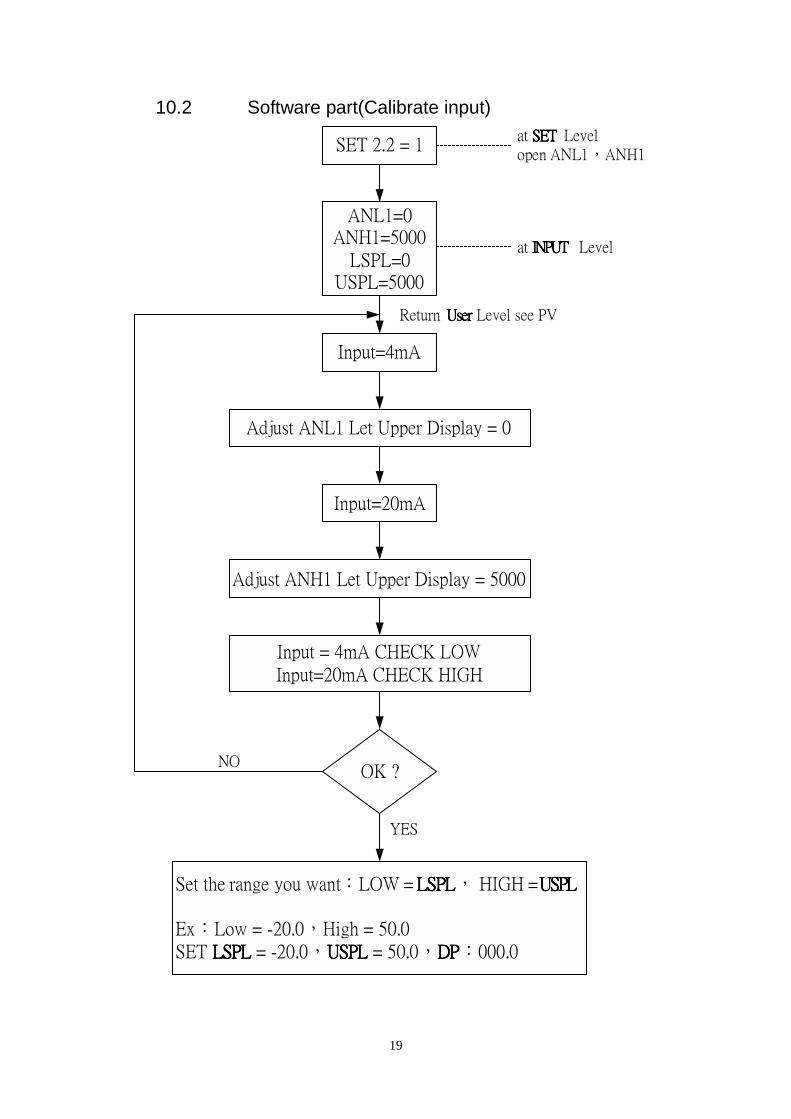
10.2 Software part(Calibrate input)
SET 2.2 = 1
ANL1=0ANH1=5000
LSPL=0USPL=5000
Adjust ANL1 Let Upper Display = 0
Input=4mA
Input=20mA
Adjust ANH1 Let Upper Display = 5000
Input = 4mA CHECK LOWInput=20mA CHECK HIGH
OK ?
Set the range you want:LOW = LSPLLSPLLSPLLSPL, HIGH =USPLUSPLUSPLUSPL
Ex:Low = -20.0,High = 50.0SET LSPL LSPL LSPL LSPL = -20.0,USPL USPL USPL USPL = 50.0,DPDPDPDP:000.0
at SET SET SET SET Levelopen ANL1,ANH1
at INPUT INPUT INPUT INPUT Level
Return UserUserUserUser Level see PV
YES
NO

20
11. Special Function Description:::: 11.1 LEVEL 4 (Set Level)
SET 1
SET 9
SET 0
INP2
OUTY
Input 2 mode setting as below
Output Mode setting as below
11.1.1 Second input mode INP2=0 Non ( TB MODEL ONLY ) INP2=1 10~50mV / 4~20mA / 2~10V INP2=2 0~50mV / 0~20mA / 0~10V
11.1.2 Output mode OUTY=0 Single Output OUTY=1 Double Output OUTY=2 None OUTY=3 Motor Valve OUTY=4 1φSCR (Single Phase Control)
OUTY=5 3φSCR (Three Phase Control)

21
11.2 RAMP & SOAK ( TB MODEL ONLY ) 11.2.1 RAMP:::: I. Please set “SET2.1=1”(Display AL3),”SET4.1=1” (Display ALD3) II. ALD3=9 at INPUT Level III. RAMP menu will be displayed (replace AL3)
RAMP
0 0 0 0
Range:00.00 ~ 99.99Unit:℃ / min(If RAMP not used,set ALD3=0)
11.2.2 SOAK: I. ALD1 / ALD2=19 II. AL1 / AL2 will be display
AL1
0 0 . 0 0Range:00.00 ~ 99.59(Hour.Minute)
11.2.3 Example:::: SV=100℃,RAMP=10.00 (℃/min),AL1=00.10 min,PV=25℃
100℃℃℃℃
PV=25℃℃℃℃
¢J
tttt
power on 5sec.
Time onif PV SV(100 )≧≧≧≧ ℃℃℃℃
Time upAL1 on
SV=PV at start RAMP function
SV=SV+RAMP
AL100.10
00.0100.10
on delay timeset time
1sec.

22
11.3 REMOTE SV (TB MODEL ONLY) 11.3.1 Hardware must be mounted 11.3.2 Set INP2 to1 or 2 (calibration use ANL2,ANH2) 11.3.3 SET 0.3=0 means local SV 11.3.4 SET 0.3=1 means remote SV from Input 2 channel 11.4 Alarm Time ALT1/ALT2/ALT3 description (TB MODEL
ONLY) 1. ALT1=0 means flicker if AL1 is on 2. ALT1=99.59 means alarm if AL1 is on 3. ALT1=00.01 ~ 99.58 means AL1 is on delay timer(* use for large EMI
affect controller) 11.5 Renew function “HYSM” “SETA”
SETA
0 0 0 0
If SETA.1=1,AL1 relay reversed
If SETA.4=0 ,program run alarmIf SETA.4=1,program end alarm
} If TB100 ALM "b" contactis needed
} PTB model only
If SETA.2=1,AL2 relay reversed
If SETA.3=1,AL3 relay reversed
11.6 Function SET8 11.6.1 SET8.1=0 Non
SET8.1=1 program repeat ( PTB model ) 11.6.2 SET8.2=0 Non (PTB only)
SET8.2=1 Power failure access 11.6.3 SET8.3=0 Zero start (PTB only)
SET8.3=1 PV start11.6.4 SET8.4=0 Non
SET8.4=1 display will be transferred to single display (Don’t set this Bit) *SET8=0000 can return double display

23
11.7 Function SET9 11.7.1 SET9.1=0 Non
SET9.1=1 PV / SV switching ( use for single display so please don’t set this Bit.)
11.7.2 SET9.2=0 Non SET9.2=1 PTB models :Timer change from H.M to M.S
11.7.3 SET9.3=0 Non SET9.3=1 Transmission SV
11.7.4 SET9.4=0 Non SET9.4=1 Transmission PV
11.8 SET0 11.8.1 SET0.1=0 Non
SET0.1=1 TTL communication SV output 11.8.2 SET0.2=0 Non
SET0.2=1 Rate for AL3 (ALD3=0) (see Application 1,P.23) 11.8.3 SET0.3=0 Non
SET0.3=1 Remote SV 11.8.4 SET0.4=0 Motor Valve close = “b” out
SET0.4=1 Motor Valve close = “a” out 11.9 WAIT at INPUT Level
WAIT=0 means “no wait” WAIT≠0 means “wait”

24
Application
App1. TTL communication::::SV output & RATE function # Open RATE function (use for slave) 11.10 Open Rate:SET0.2=1 11.11 Open AL3:SET2.1=1 11.12 Open ALD3:SET4.1=1 11.13 ALD3=0 at INPUT Level 11.14 Slave SV = (RATE÷9999)×master SV # Example::::
SD
SG
PTB900master
RD
SG
TB900slave 1
RD
SG
TB900slave 2
SV OUT (SET0.1=1)IDNO=0 (SET5.4=1)BAUD=2400(SET5.4=1)
IDNO=1 (SET5.4=1)BAUD=2400(SET5.4=1)open RATE function
IDNO=2 (SET5.4=1)BAUD=2400(SET5.4=1)open RATE function
Connect Diagram
Time Chart
Time1 hour
1000
SV_1=1000TM_1=01.00 hourOUT_1=100%OUT_2=0%
Time1 hour
900
SV=0slave 1 SV=900RATE SET 9000
Time1 hour
800
SV=0slave 2 SV=800RATE SET 8000
( All reach to the max value at the same time )
SV SV SV

25
App2. Single Phase Control ( for SCR module) # Available Models:::: TB900 / PTB900 ,, TB700 / PTB700 # Data Change:::: OUTY=4
CLO1=0,,,,CHO1=5000 if use for resistance load CLO1=0,,,,CHO1=4000 if use for inductor load
Short
CONTROLLER
G 1
G 2
K 1
K 2
PRO
T
K1
K 2
G 1
S R
G 2
FASTFUSE
U V
SCRModule
** Controller source phase must be same as load source phaseLOAD

26
App3. Single Phase Control ( for TRIAC module) # Available Models:::: TB900 / PTB900 ,,,TB700 / PTB700 # Data Change:::: OUTY=4
CLO1=0,,,,CHO1=5000 if use for resistance load CLO1=0,,,,CHO1=4000 if use for inductor load
Short
CONTROLLER
G1
G2
K1
K2
PRO
T
T1
G1
S R
FASTFUSE
U V
TRIACModule
T2
MM
VU1/2W100Ω 0.1uf/630V
AC
** Controller source phase must be same as load source phase
LOAD

27
App4. Three Phase Control # Available Models:::: TB900 / PTB900 # Data Change:::: OUTY=5
CLO1=0,,,,CHO1=5000 only if use for resistance load
CONTROLLER
Short
K 1G 1
K 2G 2
K 3G 3
TSR
FASTFUSE
U V
DIODE/SCRModule
W
K 2
K 2
G 2
K 3
PRO
T
G 3
G 1
3φ LOAD

28
App5. Single Phase Zero Control # Available Models:::: TB900 / PTB900 ,,,TB700 / PTB700
TB100 / PTB100 # Data Change:::: OUTY=0
CYT1=1
Short
G 2
CONTROLLER
G 1
G 2
PRO
T
R S
G 1
FASTFUSE
U V
SCRModule
CYCLE TIME = 200 mSEC.
OFFON
TIME CHART:

29
App6. Three Phase Zero Control # Available Models:::: TB900 / PTB900 # Data Change:::: OUTY=0
CYT1=1
RG 1
Short
CONTROLLER
WE CAN SUPPLYHEATER SINK
RG 1
TG 1
RG 2
TG 2
PRO
T
TG 2
TG 1
SR
FASTFUSE
U V
SCRModule
RG 2
T
W
CYCLE TIME = 200 mSEC.
OFFON
TIME CHART:

30
App7. Motor Valve Control # Available Models:::: TB900 / PTB 900 ,,TB600 / PTB600
TB700 / PTB700 ,,,TB400 / PTB400, TB100 / PTB100 # Data Change:::: OUTY=3
CYT1=1 ~ 100sec.( Normally set 5 sec.) RUCY=5 ~ 200 sec.
1. CYT1 is the cycle time of Open / Close 2. RUCY is the running time of motor valve 0 ~ 100%
MOTOR VALVE
CONTROLLER
CLOSE
OPEN
COMOPEN
CLOSE
COM
OUT1Relay
OUT2Relay
R
S