temperature sensors temperature...
TRANSCRIPT

66 glass machinery plants & accessories 2/2014
tem
pe
ratu
re s
en
sors
TEMPERATURE SENSORS
he function of the feeder forehearth is to provide gobs of glass to the form-
ing machine at a constant, uni-form temperature suitable for the particular forming process, at a constant weight and shape and at the required speed of the forming machine. The most important physical parameter for the forming process is the glass viscosity and as this var-ies on a logarithmic scale with glass temperature (small changes in temperature producing large changes in viscosity), precise forehearth temperature control
is essential if consistent feeder operation and efficient glassware production are to be maintained.
The actual gob temperature is normally controlled indirectly by controlling the equalizing section temperature of the forehearth and measuring the gob temperature periodically with a portable infra-red pyrometer. Some companies install thermocouples in the feed-er spout but these temperature readings are significantly affected by the location of the thermocou-ple and the feeder tube rotation direction and speed. Although the gob temperature is of prime
T
PSR:
GLASS
TEMPERATURE
MEASUREMENT IN
FOREHEARTHS AND
DISTRIBUTORS
Precise forehearth and
distributor temperature
control is essential
if consistent feeder
operation and efficient
glassware production
are to be maintained.
To control the glass
temperature it must be
accurately measured.
Here we describe
and compare the
temperature sensors
recommended and
used in our forehearth
and distributor systems.

glass machinery plants & accessories 2/2014 67
importance, many glass companies still do not measure this at all and rely entirely on the measurement and control of the equalizing section temperature.
The uniformity of the gob temperature can be evaluated on a qualitative basis by observing the formation of the gob prefer-ably with the feeder tube stopped from rotating. This assumes that all the feeder expendable refrac-tory parts have been correctly selected and installed and that the feeder mechanism has been correctly adjusted and is operat-ing correctly. If the gob does not develop straight from the orifice and curls to one side this indi-cates that the gob is cold on the side to which the gob curls. If the gob curls towards the forehearth then the bottom glass is too cold and the rear cooling sections need increasing in temperature.
If the gob curls away from the forehearth then the bottom temperature is too high and the rear cooling sections need to be reduced in temperature.
Before the development and widespread use of suitable per-manently installed tri-level (tri-plex) thermocouples, these
observations were used for setting up the forehearth zone temperatures.
The use of tem-porary portable tri-level thermo- couples at job changes alongside these observations eventually lead to the use of perma-nently installed tri-level thermocou-ples.
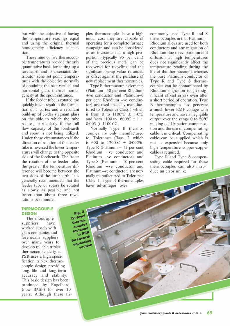
TRI-LEVEL THERMOCOUPLESThe thermal homogeneity of
the glass entering the spout can be used as a quantitative guide to the uniformity of the gob temperature. This is evaluated by installing three tri-level (tri-plex) thermocouples through the equalizing section superstructure across the spout entrance. These thermocouples have three hot junctions located at one inch (25 millimetres) off the channel bot-tom (Lower), in the middle of the glass stream (Middle) and one inch (25 millimetres) below the glass surface (Upper).
They are normally arranged in a nine-point grid with one on the centre line of the forehearth
and one on either side (Left and Right) at a distance equal to a third of the channel width from the centre line. The thermo-couples should be as close to the spout entrance as possible but not so close that their readings are readily affected by changes in the direction and speed of rotation of the feeder tube or rotors. They should be located between burner positions to pre-vent possible damage to the side thermocouple sheaths by flame impingement, with a peephole positioned to allow viewing of the thermocouples. The thermocou-ples are typically located 14.3/8 inches (365 millimetres) back from the spout entrance.
The spread of temperatures
Fig. 1 - A feeder forehearth providing gobs to the forming
machine
PSR standard thermocouple positions
W
365m
m
W/3W/3

over the nine-point grid can be expressed mathematically as a percentage thermal homogene-ity efficiency figure as adopted by several glass companies. In comparing these thermal homo-geneity figures the location of the thermocouples and the method of calculation must be taken into account.
PSR uses the following 9-point and 5-point thermal homogene-ity calculations:
For the 9-point grid, six posi-
tive horizontal temperature dif-ferences ‘ H’ are calculated from the values
(U.C.–U.L.),(U.C.–U.R.),(M.C.–M.L.),(M.C– M.R.),(L.C.–L.L.) and (L.C.–L.R.)by subtracting the lowest value
from the highest value.Three positive vertical temper-
ature differences ‘ V’ are calcu-lated from the highest and lowest values of
(U.L., M.L. and L.L.),(U.C., M.C. and L.C.) and(U.R., M.R. and L.R.)by sub-
tracting the lowest value from the highest value.
The 9-point forehearth ther-mal homogeneity efficiency is then calculated as follows:
9-Point Thermal Homogeneity Efficiency
(%) = [1–( H + V)/M.C.] x 100.
The triangular area formed by the Upper Centre (U.C.), Lower Left (L.L.) and Lower Right
(L.R.) thermocouple junc-tions contains the glass primarily used to form the gob and it is considered that these temperatures have a direct bearing on gob temperature distri-bution and ultimately on the glass distri-bution in the article being manufactured.
For this reason many glass compa-nies only use the
five points within this trian-gle in the calculation.
This allows the upper and middle sidewall temperatures to be operated at higher tempera-tures if necessary to increase the lower sidewall temperatures without producing a lower ther-mal homogeneity efficiency fig-ure.
For the 5-point grid, two posi-tive horizontal temperature dif-ferences ‘ H’ are calculated from the values
(L.C. – L.L.) and (L.C.– L.R.) by subtracting the lowest value from the highest value.
One positive vertical temper-ature difference ‘ V’ is calcu-lated from the highest and low-
est values of (U.C., M.C. and L.C.) by subtracting the low-est value from the highest value.
The 5-point forehearth ther-mal homogene-ity efficiency is then calculated
as follows:5-Point Thermal Homogeneity
Efficiency (%) = [1–3 x ( H + V)/M.C.] x 100.As in the 5-point calculation
there are only two horizontal temperature differences and one vertical temperature difference compared with the six horizon-tal temperature differences and three vertical temperature dif-ferences in the 9 point calcula-tion, the temperature differences are multiplied by 3 to make the typical differences of the 5 points represent the total differences of the 9 points and to make the 9-point and 5-point calculations mathematically equivalent.
Other methods of calculating the forehearth thermal homoge-neity efficiency value are used by different companies but we believe that the versions of the calculations described above best represent the glass thermal homogeneity because if all 9 or 5 thermocouple temperatures are the same both thermal homo-geneity efficiency values calcu-late at 100 per cent and values greater than 100 per cent are not possible. Other calculations attaching more importance to the sidewall temperatures being hotter than the centre tempera-tures can provide thermal homo- geneity efficiency values greater than 100 per cent. The logic behind this is that as these tem-peratures are measured a dis-tance back from the spout the side temperatures will cool faster than the centre line temperatures due to the greater heat losses. So if the side temperatures start off hotter than the centre line tem-peratures it is more likely that the temperatures across the glass width will be more even when the glass reaches the spout entrance. In some designs the centre line tri-level thermocouple is off-set further back upstream from the side tri-level thermocouples to effectively achieve the same result
TEMPERATURE SENSORS
ULMC
UC
LR
MR
UR
LCML
LL
9-point grid
MC
UC
LR
LC
LL
5-point grid
69
but with the objective of having the temperature readings equal and using the original thermal homogeneity efficiency calcula-tion.
These nine or five thermocou-ple temperatures provide the only quantitative basis for setting up a forehearth and its associated dis-tributor zone set point tempera-tures with the objective normally of obtaining the best vertical and horizontal glass thermal homo-geneity at the spout entrance.
If the feeder tube is rotated too quickly it can result in the forma-tion of a vortex and a resultant build-up of colder stagnant glass on the side to which the tube rotates, particularly if the full flow capacity of the forehearth and spout is not being utilized. Under these circumstances if the direction of rotation of the feeder tube is reversed the lower temper-atures will change to the opposite side of the forehearth. The faster the rotation of the feeder tube, the greater the temperature dif-ference will become between the two sides of the forehearth. It is generally recommended that the feeder tube or rotors be rotated as slowly as possible and not faster than about three revo- lutions per minute.
THERMOCOUPLE DESIGN
Thermocouple suppliers have worked closely with glass companies and forehearth suppliers over many years to develop reliable triplex thermocouple designs. PSR uses a high speci-fication triplex thermo-couple design providing long life and long-term accuracy and stability. This basic design has been produced by Engelhard (now BASF) for over 30 years. Although these tri-
plex thermocouples have a high initial cost they are capable of operating for a complete furnace campaign and can be considered as an investment as a high pro-portion (typically 95 per cent) of the precious metal can be recovered for recycling and the significant scrap value refunded or offset against the purchase of new replacement thermocouples.
Type B thermocouple elements (Platinum– 30 per cent Rhodium +ve conductor and Platinum–6 per cent Rhodium –ve conduc-tor) are used specially manufac-tured to Tolerance Class 1 which is from 0 to 1100°C ± 1·0°C and from 1100 to 1600°C ± 1 + 0·003 (t–1100)°C.
Normally Type B thermo-couples are only manufactured to Tolerance Class 2 which is 600 to 1700°C ± 0·0025t. Type R (Platinum – 13 per cent Rhodium +ve conductor and Platinum –ve conductor) and Type S (Platinum – 10 per cent Rhodium +ve conductor and Platinum –ve conductor) are nor-mally manufactured to Tolerance Class 1. Type B thermocouples have advantages over
commonly used Type R and S thermocouples in that Platinum – Rhodium alloys are used for both conductors and any migration of Rhodium due to evaporation and diffusion at high temperatures does not significantly affect the temperature reading during the life of the thermocouple whereas the pure Platinum conductor of Type R and Type S thermo-couples can be contaminated by Rhodium migration to give sig-nificant off-set errors even after a short period of operation. Type B thermocouples also generate a much lower EMF voltage with temperature and have a negligible output over the range 0 to 50°C making cold junction compensa-tion and the use of compensating cable less critical. Compensating cable can be supplied which is not as expensive because only high temperature copper-copper cable is required.
Type R and Type S compen-sating cable required for these thermocouples can also intro-duce an error unlike
glass machinery plants & accessories 2/2014
Fig. 2
Tri-level
thermo-
couples
installed
in PSR
forehearth
equalizing
section

70 glass machinery plants & accessories 2/2014
tem
pe
ratu
re s
en
sors
TEMPERATURE SENSORS
the copper-copper cable used with Type B thermocouples. For example Type R and Type S compensating cable up to a tem-perature of 1000°C and with the connection to the thermocou-ple between 0 and 100°C has a tolerance of ± 2·5°C. Type R and Type S thermocouples were popular for use with the older analogue instrumentation due to their higher millivolt output sig-nals which are easier to measure but this is not now a considera-tion with modern microprocessor based digital instrumentation.
In this thermocouple design there are no connections in the thermocouple head with the pre-cious metal element wires pass-ing directly through the sealed thermocouple head and extend-ing for 2 metres so that the con-nection to the field wiring can be made in an insulated and sealed junction box in a cooler location at the side of the forehearth.
This connection is made with plugs and sockets which are included with the thermocouple. This avoids any junction errors due to connections in the ther-mocouple head being at the high ambient temperature directly above the forehearth. The two-metre long precious metal exten-sion leads (not compensating cable) are individually covered in a heat resistant glass fibre sleeve together with an overall glass fibre sleeve covering all three leads.
For junction identification the Upper junction is sleeved in black and is numbered 1 on the plug, the Middle junction is sleeved in blue and is numbered 2 on the plug and the Lower junction is sleeved in red and is numbered 3 on the plug. The numbers are engraved on the plugs to pro-vide a permanent identification. A sealed and insulated junction box is included in our supply together with the necessary ther-mocouple mounting brackets and insulators.
The junction box protects the plug and socket connections from oxidation and oil contamination due to the relatively high ambient temperature and oily atmosphere around the forehearth. The mounting brack-ets hold the thermo-couples in the correct position and shield the thermocouple heads from the heat from the forehearth superstructure and exhaust flues. The insulators isolate the thermocouples from the forehearth steel-work and mounting bracket to prevent any electrical inter-ference from electric boosting systems.
The thermo- couple has a 15-millimetre out-side diameter and 1 0 - m i l l i m e t r e inside diameter recrystallized alu-
Fig. 3 - Thermocouple junction
box located at side of forehearth.
Access door is open to show plug
and socket connections

glass machinery plants & accessories 2/2014 71
recrystallized alumina sheath.Unlike normal platinum and
platinum-rhodi-um alloys which are corroded by amber glass and have a relatively short life, the ODS Platinum is suitable for use in all glass types and colours.
The three ther-mocouple junc-tions use 0·5 mil-limetres thick Type B thermocouple wire within sin-gle recrystallized alumina twin bore insulators.
The three junc-tions are normally located 1/2 inch (13 millimetres), 2.1/2 inches (64 milli-metres) and 4.1/2 inches (114 milli-metres) from the tip of the thermocouple. The thermocouple is normally installed 1/2 inch (13 millimetres) off the channel block base being designed for use in a nominal 6 inches (152 millime-tres) glass depth. The thermocouple can be lowered the 1/2 inch (13 millimetres) to the channel base if neces-sary to accommodate a lower nominal glass depth of 5.1/2 inches (140 millimetres) or even 5 inches (127 mil-limetres) but other ther-mocouple junction loca-tions for different glass depths can also be pro-vided. If the thermocou-ple is to be installed on the channel bottom then the weight of the thermo-couple must be support-
ed by the thermocouple bracket to prevent deformation of the thimble over time. The thickened thimble bottom protects against possible erosion due to vibration.
The overall length of our standard triplex thermocouple for installation across the spout entrance in an equalizing section is 36 inches (915 millimetres) excluding the thermocouple head made up of an 8 inches (203 millimetres) long, 22 millimetres outside diameter Inconel back-ing tube and a 28 inches (711 millimetres) long, 15 millimetres outside diameter, 10 millimetres inside diameter recrystallized alumina sheath. A 40 millimetres diameter access hole is required in the forehearth roof for instal-lation of the thermocouple.
Longer thermocouples are supplied for other locations such as the forehearth entrance. Longer ODS Platinum thimbles are used for greater glass depths.
ADVANCED CONTROL STRATEGIES
The Upper Centre triplex ther-mocouple junction is used as the control sensor for the equalizing section. This must not be located much more than 1 inch (25 mil-limetres) below the glass surface, particularly for coloured glasses, otherwise temperature control cycling will occur due to exces-sive process lag. In our advanced temperature control systems the Middle Centre and Lower Centre junctions are used in secondary Cascade control loops to trim the cooling section set point tem-peratures, automatically optimiz-ing the centre line vertical glass temperature homogeneity at the spout entrance.
The Lower Left and Lower Right junctions are used in sec-ondary Trim control loops to trim the left and right-hand side firing, automatically optimizing the hor-izontal glass temperature homo-geneity. The secondary Cascade
Fig. 4 - Typical PSR Thermocouples. Single point (simplex) shown right. Tri-level (triplex) shown left
mina sheath protected from the glass with an 8-inch (203 millimetres) long, 0·38-millimetre thick Oxide Dispersion Strengthened (ODS) Platinum thimble thickened to 1·00 millimetres at the tip which is cemented and fired on to the

72 glass machinery plants & accessories 2/2014
tem
pe
ratu
re s
en
sors
TEMPERATURE SENSORS
and Trim control loops operating together automatically optimise the overall thermal homogeneity at the spout entrance.
INFRA-RED FIBROPTIC THERMOMETERS
For measurement of forehearth cooling section temperatures and distributor section temperatures including the throat riser PSR normally recommends and uses infra-red fibroptic thermometers.
The Land Fibroptic Model FG supplied by Land Instruments is a popular analogue instrument of which we have supplied many units over the years although for the past 9 years we have used the Infratherm IS 50-LO/GL, a digital instrument supplied by Lumasense Technologies (for-merly Impac). The thermom-eter consists of an optical head lens mounted in a purge air assembly which is sighted verti-cally from above the forehearth or distributor roof onto the glass surface through an Inconel sight-ing tube. The opti-cal head is con-nected to the ther-mometer processor unit via a 5-metre long stainless steel coated fibroptic light guide which allows the processor unit to be mounted in a junc-tion box in a cooler location at the side of the forehearth or dis-tributor rather than on top of the forehearth. This allows the proces-sor unit to operate accu-rately without the need for air or water cooling as was required with the
infra-red pyrometers originally used over 30 years ago. The maximum ambient temperature for the optical head and light guide is 250°C whereas for the processor unit it is 70°C. The purge air assembly protects the optical head objective lens sur-face from contamination with dust or moisture.
It requires a supply of instru-ment quality (dry and oil free) compressed air at an approxi-mate volume of 65 to 100 litres per minute (4 to 6 cubic metres per hour) and generates a cone shaped air stream.
The optical head is connected to the purge air assembly with a quick release bayonet connector allowing easy
removal for lens checking and cleaning as well as for view-ing down the sighting tube for checking against a portable infra-red thermometer.
A purge air control panel incorporating a pressure regula-tor, water filter, oil filter, indi-vidual flow indicator/regulator rotameter for each fibroptic and low pressure switch for remote alarm monitoring is included in our supply to ensure an ade-quate supply of purge air to each fibroptic thermometer. A 610 millimetres long Inconel sighting tube is used to allow the optical head to be mounted high on top of the forehearth superstructure steelwork on a special mount-
ing bracket/heat shield to protect the optical head and light guide from the heat exhausted from the combustion and cooling flues. The narrow sight-ing angle of the ther-mometer objective lens allows sighting within the 27 millimetres inter-nal diameter Inconel sighting tube and the 40 millimetres diam-eter access hole in the forehearth roof block to the glass surface. The Inconel sighting tube passes through a 134 millimetres thick fibroptic sight-ing block above the forehearth roof block to protect the surrounding roof block insulation and enters 25 milli- metres into the external face of the roof block to ensure that the sighting block is correctly aligned with the access hole in the roof block. The infrared radia-
Fig. 5 - Fibroptic thermometer, purge air
assembly and inconel sighting tube located
above the forehearth
glass machinery plants & accessories 2/2014 73
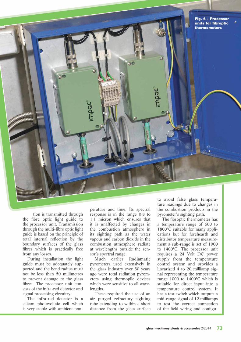
tion is transmitted through the fibre optic light guide to the processor unit. Transmission through the multi-fibre optic light guide is based on the principle of total internal reflection by the boundary surfaces of the glass fibres which is practically free from any losses.
During installation the light guide must be adequately sup-ported and the bend radius must not be less than 50 millimetres to prevent damage to the glass fibres. The processor unit con-sists of the infra-red detector and signal processing circuitry.
The infra-red detector is a silicon photovoltaic cell which is very stable with ambient tem-
perature and time. Its spectral response is in the range 0·8 to 1·1 micron which ensures that it is unaffected by changes in the combustion atmosphere in its sighting path as the water vapour and carbon dioxide in the combustion atmosphere radiate at wavelengths outside the sen-sor’s spectral range.
Much earlier Radiamatic pyrometers used extensively in the glass industry over 50 years ago were total radiation pyrom-eters using thermopile devices which were sensitive to all wave-lengths.
These required the use of an air purged refractory sighting tube extending to within a short distance from the glass surface
to avoid false glass tempera-ture readings due to changes in the combustion products in the pyrometer’s sighting path.
The fibroptic thermometer has a temperature range of 600 to 1800°C suitable for many appli-cations but for forehearth and distributor temperature measure-ment a sub-range is set of 1000 to 1400°C. The processor unit requires a 24 Volt DC power supply from the temperature control system and provides a linearized 4 to 20 milliamp sig-nal representing the temperature range 1000 to 1400°C which is suitable for direct input into a temperature control system. It has a test switch which outputs a mid-range signal of 12 milliamps to test the correct connection of the field wiring and configu-
Fig. 6 - Processor units for fibroptic thermometers

74 glass machinery plants & accessories 2/2014
tem
pe
ratu
re s
en
sors
TEMPERATURE SENSORS
ration of the control system temperature controllers and indi-cators.
The signal processing circuit-ry is digital allowing easy and quick setting up of the instru-ment using a digital interface to a PC running the configuration software. To complement the instrument a calibration source is available allowing quick and easy checking and adjustment of the thermometers.
The fibroptic thermometer has a modular construction allow-ing easy replacement of major component parts, in some cases without the need to return the instrument to the manufacturer.
The fibroptic thermometer measures essentially the surface glass temperature (the top 25 millimetres for white flint glass, 5 millimetres for amber glass and 4 millimetres for green glass) and is installed sighting vertically on the glass surface at the end of each control zone.
To obtain a correct tempera-ture measurement of an object with a radiation thermometer it is necessary to set the emissivity value for the object.
The emissivity of an object is a measure of the object’s emis-sion and absorption of radia-tion at a particular wavelength and temperature compared to a perfect black body which has an emissivity of 100 per cent. As the thermometer is sighting at right angles to the glass surface in a totally enclosed forehearth chamber the emissivity setting on the instrument is set at 100 per cent as in this situation the glass approximates to a total black body.
SINGLE POINT THERMOCOUPLES
Some customers prefer to use single point thermocouples rath-er than fibroptic thermometers in the cooling sections. In this case an equivalent single point (sim-plex) thermocouple design to the
same high specification as the tri-level (triplex) thermocouple design can be supplied.
The single point thermocou-ples have a shorter ODS Platinum thimble as the single junction is only installed 1 inch (25 milli-metres) into the glass surface but they have a longer over-all length as they are mounted in brackets/heat shields high on the superstructure steelwork in the same location as the fibrop-tics would be installed to protect the thermocouple head from the heat from the combustion and cooling exhausts. A peephole is positioned opposite the thermo-couple location to allow correct positioning of the thermocouple in the glass.
The thermocouple is lowered by a colleague whilst being viewed through the peephole. When the thermocouple tip touches the glass surface as indicated by the tip of the thermocouple merg-ing with its own reflection in the glass surface the thermocouple backing tube is marked and then the thermocouple is lowered a
Fig. 7 - Purge
air control
panel for 6
fibroptic
thermometers

glass machinery plants & accessories 2/2014 75
further 11/2 inches (38 milli-metres) to put the thermocouple junction 1 inch (25 millimetres) into the glass surface.
Some customers also use tri-level (triplex) thermocouples in the cooling sections but whilst these provide additional infor-mation to show the temperature gradients through the glass depth along the length of the forehearth this is an expensive option and does not really provide any infor-mation that could not be ascer-tained from the resultant tri-level thermocouple temperatures at the spout entrance.
PSR has used both fibroptic thermometers and single point thermocouples in cooling sec-tions and on balance prefers to use the fibroptic thermometers as they are a non-contact sensor.
Both sensors provide good results and troublefree operation providing that they are installed correctly. Each sensor has its own advantages and disadvan-tages which are summarized and compared below.
ADVANTAGES AND DISADVANTAGES OF INFRA-RED THERMOMETERS
-vide non-contact temperature measurement and are therefore not damaged by and cannot contaminate the glass. Their readings cannot be affected by electric boosting in the glass.
are stable and do not deterio-rate with time. Their calibra-tion can be checked and re-set if necessary. Good installation and maintenance techniques can provide an almost unlim-ited lifespan.
require an instrument qual-ity compressed air supply for purging of the objective lens and a 24 Volt D.C. power sup-ply for the processor unit.
-
vide a high level, linear 4 to 20 milliamp output signal that is less affected by electrical inter-ference than a thermocouple millivolt signal and which can easily be scaled to provide improved signal resolution in a temperature control system.
a fast response time reacting to temperature changes much faster than a thermocouple.
-ure essentially the surface glass temperature and cannot meas-ure the temperature at differ-ent points throughout the glass depth.
-fer takes place through the glass surface infra-red ther-mometers are appropriate for controlling forehearth and dis-tributor zone temperatures.
used in throat riser areas to measure the entrance temper-ature to the distributor from the furnace providing that no cooling is employed over the throat riser section.
surface glass temperature is important in cooling sections to ensure that the glass surface is not being overcooled.
measure the glass surface tem-perature irrespective of chang-es in the furnace glass level.
-face as can occur in the vicin-ity of stirrers can result in a fluctuation in the temperature measured by an infra-red ther-mometer due to surface optical effects.
ADVANTAGES AND DISADVANTAGES OF THERMOCOUPLES
-tact with the glass and can be corroded and damaged by the glass flow and any foreign materials such as stones pass-
ing through with the glass. The thermocouple sheath needs to be protected with an appro-priate platinum thimble to pre-vent corrosion by the glass and provide an acceptable lifespan.
to electrical interference from electric boosting in the glass and need to be isolated from the forehearth and mounting steelwork.
deteriorate with time at high temperatures and the thermo-couple type should be selected to minimize this affect.
-not be practically checked and cannot be re-set. Faulty thermo- couples have to be replaced.
and installation can provide a long but finite lifespan.
of the thermocouples can be recovered for recycling and the significant scrap value refunded or offset against the purchase of new replacement thermocouples.
additional services.
for zone temperature meas-urement and control must be located no more than 1 inch (25 millimetres) below the glass surface otherwise tem-perature control cycling can occur due to the excessive process lag between changes in the heating or cooling and changes in the measured tem-perature.
can be significantly different from the temperature 1 inch (25 millimetres) below the glass surface particularly when cooling coloured glasses.
are set at a particular distance below the glass surface under specific operating conditions changes in the glass level due

76 glass machinery plants & accessories 2/2014
tem
pe
ratu
re s
en
sors
TEMPERATURE SENSORS
to hydraulic head loss along the forehearth at different forehearth throughputs will result in changes in the meas-urement point location and the measured temperature.
-trolled furnace glass level will result in changes in the meas-urement point location and the measured temperature.
controlled to ± 0·010 inches (± 0·25 millimetres) or better for successful thermocouple control of forehearths and dis-tributors. Glass level changes in excess of these values will result in temperature upsets due to the measurement points being closer or further away from the glass surface.
level thermocouples having junctions at different levels can measure the glass temperature throughout the glass depth for glass thermal homogene-ity evaluation and to provide a basis on which to set up fore-hearth and distributor zone temperatures.
long protection thimbles can be used in heavily cooled dis-tributor throat riser areas to measure the glass temperature entering the distributor from the furnace at glass depths not affected by the cooling which may be some 12 inches (305 millimetres) below the glass surface.At the beginning of this article
we stated that the function of the feeder forehearth is to provide gobs of glass to the forming machine at a constant, uniform temperature suitable for the par-ticular forming process, at a con-stant weight and shape and at the required speed of the form-ing machine but that the gob temperature and uniformity is normally controlled indirectly by controlling the equalizing sec-
tion temperature and the glass thermal homogeneity at the spout entrance.
The actual gob temperature not only depends on the glass temperature and thermal homo-geneity as measured in the equal-izing section at the spout entrance but also on the following factors:
superstructure insulation in the forehearth equalizing sec-tion and spout.
-lation.
around the feeder spout as it determines heat losses.
spout firing is normally manu-ally set at a fixed firing level to compensate for the heat losses at the spout so that the glass is generally neither heated nor allowed to cool greatly from the temperature in the equal-izing section.
-izing section and spout which determines the glass residence time and consequent heat loss between the measurement point in the equalizing section and the orifice.
determines the glass residence time and consequent heat loss between the measurement point in the equalizing section and the orifice.
speed of rotation as it affects the glass flow into and within the feeder spout.
stroke and action as it pushes the glass through the orifice.
-tion in cutting the gobs and shear cooling spray which may locally cool the spout and ori-fice ring.As can be seen there are many
other factors that determine the gob temperature and as this is the
final opportunity to control the temperature of the glass and hence the viscosity of the glass entering the form-ing operation we consider that measurement and con-trol of the gob temperature is of prime importance for the forming process and should not be ignored.
CONTINUOUS GOB MEASUREMENT AND CONTROL
Continuous gob tem-perature measurement and control using infra-red thermometers as well as gob monitoring by thermal imaging has been possible for many years but not widely adopted in the industry. For gob temperature measurement a two col-our infra-red thermom-eter is normally used, measuring at two dif-ferent wavelengths and comparing the ratio to minimize the affects of shear spray, steam and smoke on the reading and a peak picker is used to hold the maxi-mum temperature and ignore the shearing. These infrared ther-mometers are generally sighted on the gob at the orifice and measure a similar temperature to a portable infra-red thermo-meter. However, modern parallel shear mechanisms make it very difficult to view the gob near the orifice ring to accurately measure the gob temperature in this way.
PSR has participated in gob temperature measurement and control trials using the high spe- cification BASF Exactus GT infra-red thermometer. The advanced, high speed BASF Exactus GT infra-red thermo-meter has such a fast response time (1000 readings per second) that it can not only measure the gob temperature in free fall

glass machinery plants & accessories 2/2014 77
below the orifice and provide an accurate single average gob temperature, it can also meas-ure the longitudinal temperature profile of each individual gob and this information can be used to analyse the gob forming process and its subsequent effect on the forming process.
Whilst the gob temperatures observed on our forehearths using our normal temperature control strategies have generally been steady and consistent on multiple gob applications, the implementation of gob tempera-ture measurement and control can still contribute to a signifi-cant improvement in the glass condition for the forming pro-cess and eliminate an other-wise unknown and uncontrolled
important parameter.Alongside the gob temperature
measurement trials we have also trialled Model-based Predictive Control algorithms provided by Advanced Control Solutions Inc (ACSI) and these applied to our
normal temperature con-trol strategies have proved to be capable of providing improved thermal homogeneity and gob temperature control as well as improved temperature control response at job changes.
Fig. 8 - Looking to the future? 2 Exactus GT infrared thermometers (left of picture) sighted on double gob feeder operation (right of picture)
Holmfield, Halifax - HX3 6SX West Yorkshire - UKTel: +44 – 1422 – 254472 - Fax: +44 – 1422 – 254473
www.parkinson-spencer.co.uk
PSR PARKINSON-SPENCER REFRACTORIES LTD.