temperature - stay hungry stay foolish… – ikatlah ilmu ... · • why measure temperature? 3 -...
TRANSCRIPT
1
TemperatureTemperature

Contents
2
Topics: Slide No:• Why measure temperature? 3 - 5• Temperature terminology 6 - 8• Temperature measurement technology 9 - 13• Temperature sensors 14 - 40
Why measure temperature?
3
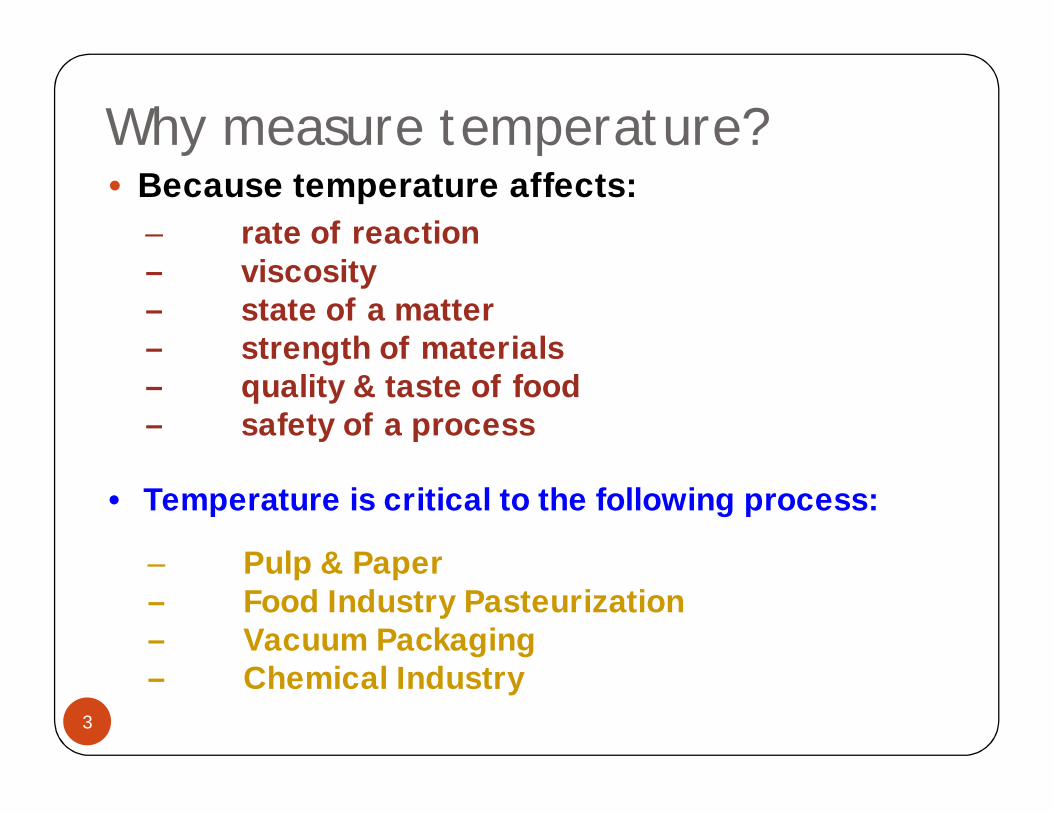
• Because temperature affects:
• Temperature is critical to the following process:
– rate of reaction– viscosity– state of a matter– strength of materials– quality & taste of food– safety of a process
– Pulp & Paper– Food Industry Pasteurization– Vacuum Packaging– Chemical Industry
Why measure temperature?4 Common Reasons
4
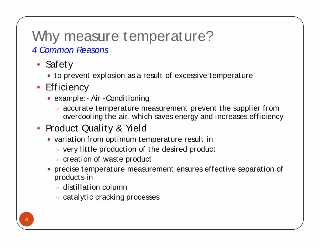
• Safety to prevent explosion as a result of excessive temperature
• Efficiency example:- Air -Conditioning
» accurate temperature measurement prevent the supplier from overcooling the air, which saves energy and increases efficiency
• Product Quality & Yield variation from optimum temperature result in
» very little production of the desired product» creation of waste product
precise temperature measurement ensures effective separation of products in» distillation column» catalytic cracking processes
Why measure temperature?4 Common Reasons
5
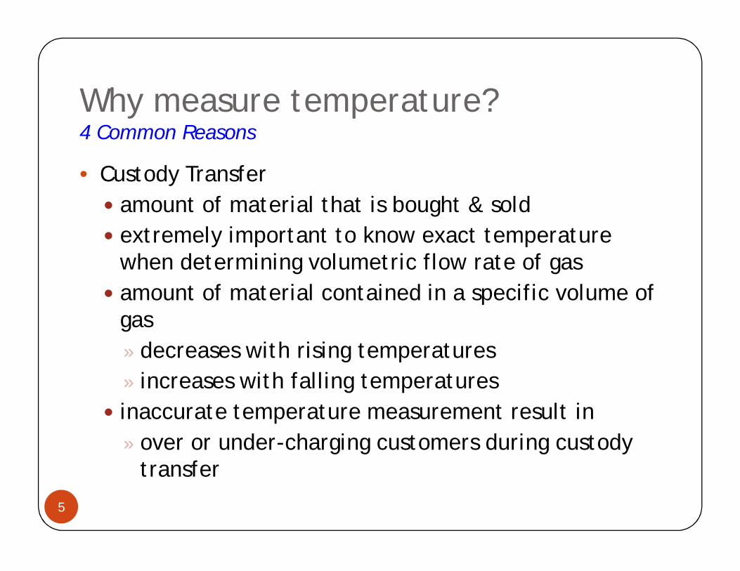
• Custody Transfer amount of material that is bought & sold extremely important to know exact temperature
when determining volumetric flow rate of gas amount of material contained in a specific volume of
gas» decreases with rising temperatures» increases with falling temperatures
inaccurate temperature measurement result in» over or under-charging customers during custody
transfer

Temperature terminologyTemperature Control Loop
6
• Temperature Loop Issues: Fluid response slowly to change in input heat Requires advanced control strategies Feedforward Control
Steam
ColdWater
HotWater
Load Disturbance
TT
TIC
I/P
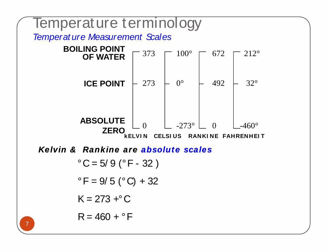
Temperature terminologyTemperature Measurement Scales
7
373 100° 672 212°
273 0° 492 32°
0 -273° 0 -460°
°C = 5/9 (°F - 32 )
°F = 9/5 (°C) + 32
K = 273 +°C
R = 460 + °F
Kelvin & Kelvin & RankineRankine are are absolute scalesabsolute scales
BOILING POINT OF WATER
ICE POINT
ABSOLUTE ZERO
kELVIN CELSIUS RANKINE FAHRENHEIT
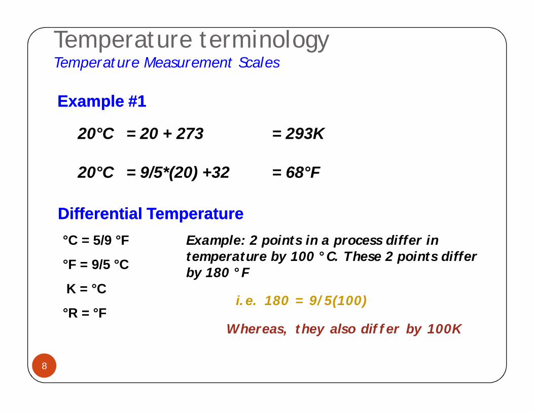
Temperature terminologyTemperature Measurement Scales
8
Differential TemperatureDifferential Temperature°C = 5/9 °F
°F = 9/5 °C
K = °C
°R = °F
Example: 2 points in a process differ in temperature by 100 °C. These 2 points differ by 180 °F
i.e. 180 = 9/5(100)
Whereas, they also differ by 100K
Example #1Example #1
20°C = 20 + 273 = 293K
20°C = 9/5*(20) +32 = 68°F
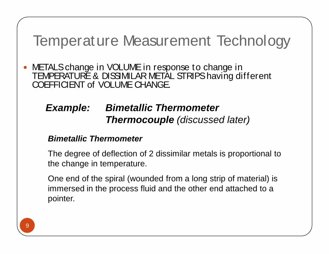
Temperature Measurement Technology
9
METALS change in VOLUME in response to change in TEMPERATURE & DISSIMILAR METAL STRIPS having different COEFFICIENT of VOLUME CHANGE.
Example: Bimetallic ThermometerThermocouple (discussed later)
Bimetallic Thermometer
The degree of deflection of 2 dissimilar metals is proportional to the change in temperature.
One end of the spiral (wounded from a long strip of material) is immersed in the process fluid and the other end attached to a pointer.

Temperature Measurement Technology
10
Example: Vapour Pressure ThermometerA bulb connected to a small bore capillary which
is connected to an indicating device.Indicating device consist of a spiral bourdon
gauge attached to a pointer.The bulb is filled with a volatile liquid and the
entire mechanism is gas tight and filled with gas or liquid under pressure.
Basically the system converts pressure at constant volume to a mechanical movement.
Expansion & Contraction of FILLED THERMAL FLUIDS
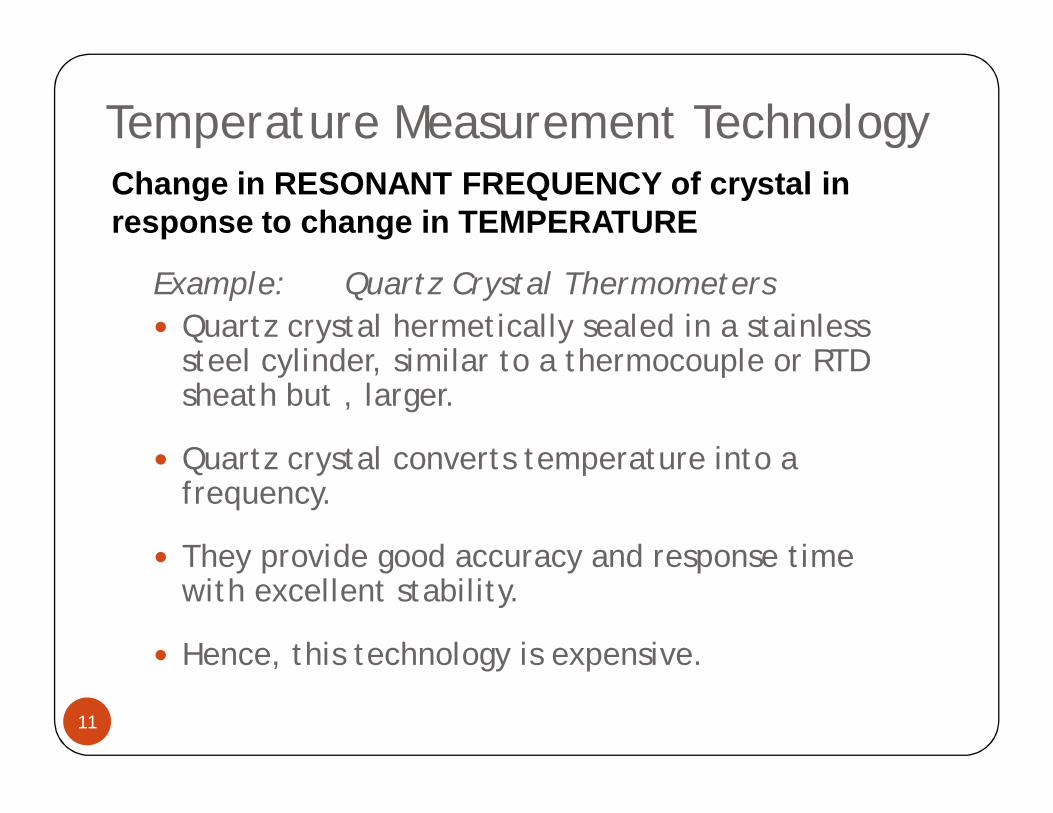
Temperature Measurement Technology
11
Example: Quartz Crystal Thermometers Quartz crystal hermetically sealed in a stainless
steel cylinder, similar to a thermocouple or RTD sheath but , larger.
Quartz crystal converts temperature into a frequency.
They provide good accuracy and response time with excellent stability.
Hence, this technology is expensive.
Change in RESONANT FREQUENCY of crystal in response to change in TEMPERATURE
Temperature Measurement Technology
12
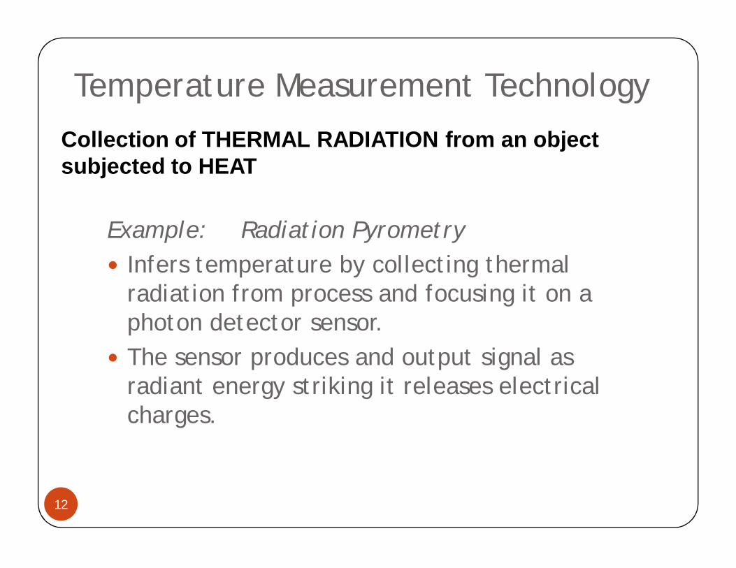
Example: Radiation Pyrometry Infers temperature by collecting thermal
radiation from process and focusing it on a photon detector sensor.
The sensor produces and output signal as radiant energy striking it releases electrical charges.
Collection of THERMAL RADIATION from an object subjected to HEAT
Temperature Measurement Technology
13
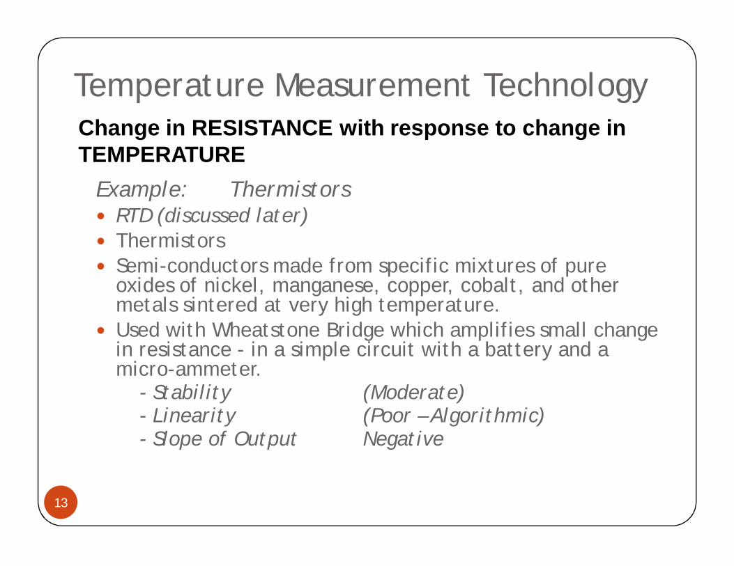
Example: Thermistors RTD (discussed later) Thermistors Semi-conductors made from specific mixtures of pure
oxides of nickel, manganese, copper, cobalt, and other metals sintered at very high temperature.
Used with Wheatstone Bridge which amplifies small change in resistance - in a simple circuit with a battery and a micro-ammeter.
- Stability (Moderate)- Linearity (Poor – Algorithmic)- Slope of Output Negative
Change in RESISTANCE with response to change in TEMPERATURE
Temperature SensorsRTDs
14
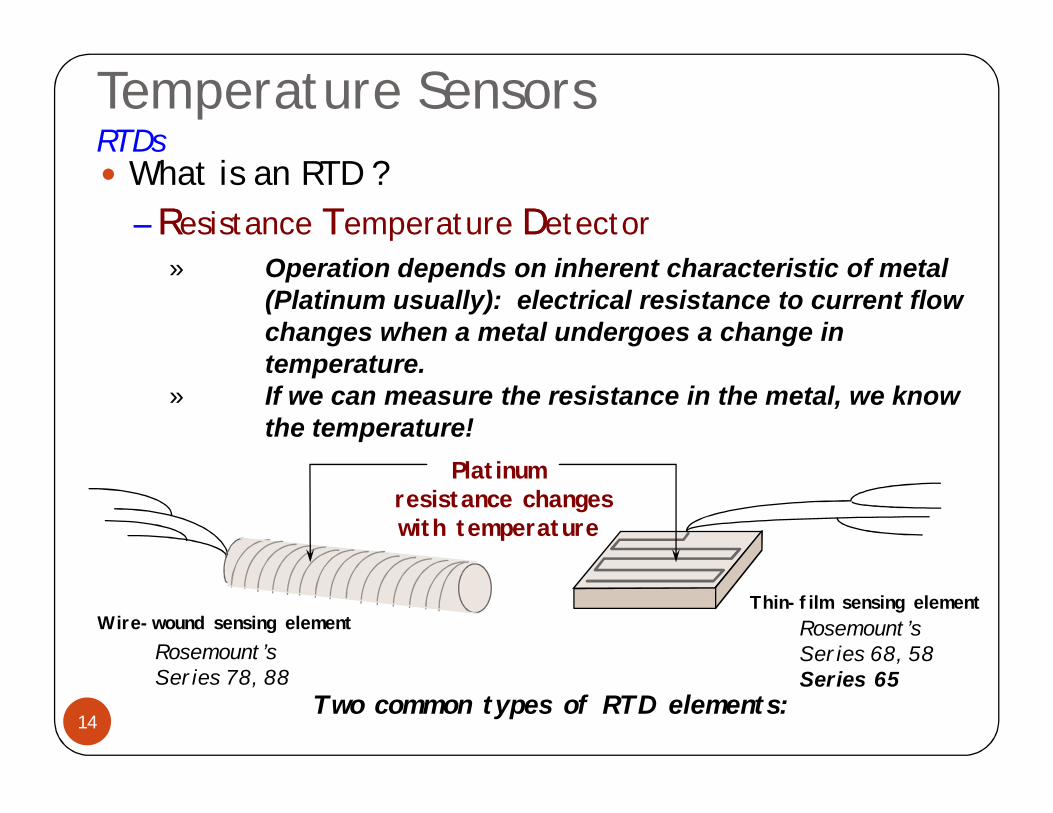
What is an RTD ?–– RResistance TTemperature DDetector
Platinumresistance changes with temperature
Rosemount’s Series 78, 88
Rosemount’s Series 68, 58Series 65
Two common types of RTD elements:
Wire-wound sensing elementThin-film sensing element
» Operation depends on inherent characteristic of metal (Platinum usually): electrical resistance to current flow changes when a metal undergoes a change in temperature.
» If we can measure the resistance in the metal, we know the temperature!
Temperature SensorsRTDs
15
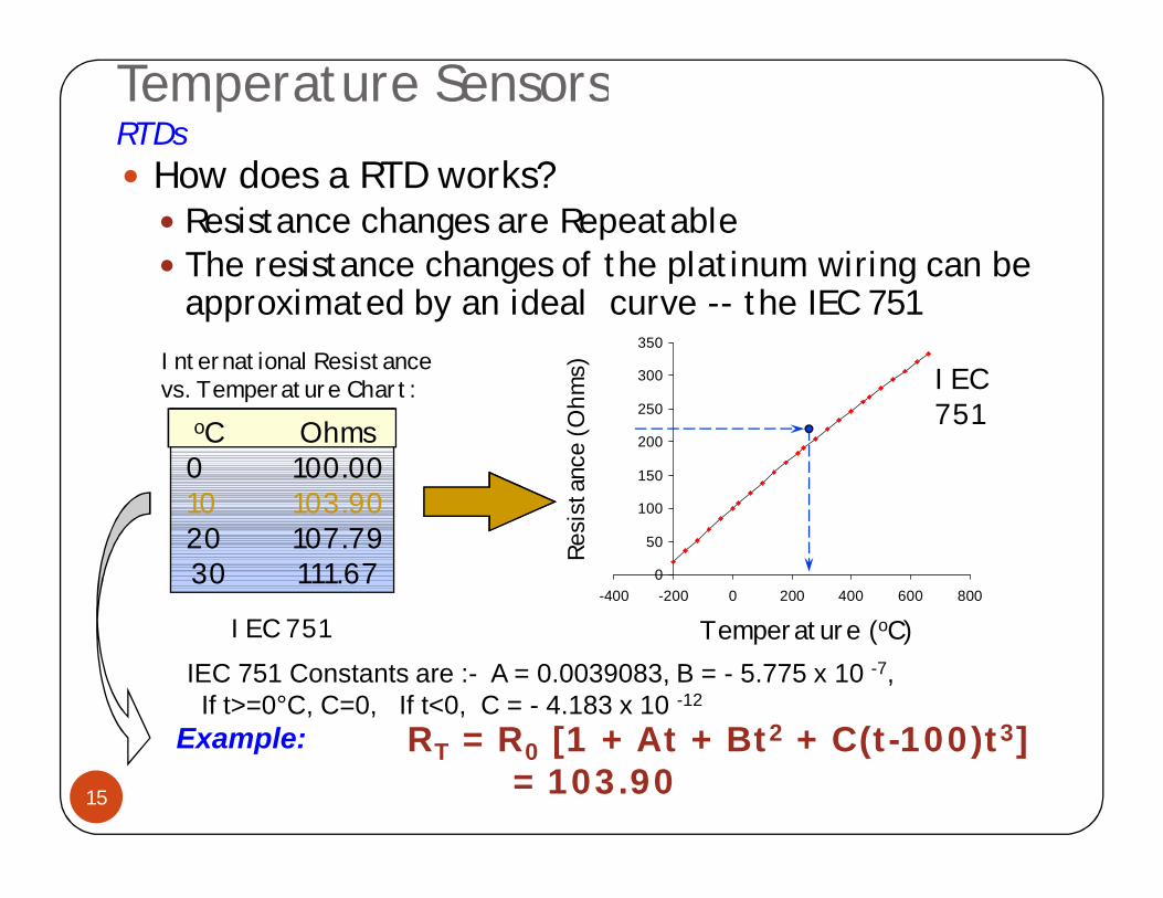
How does a RTD works? Resistance changes are Repeatable The resistance changes of the platinum wiring can be
approximated by an ideal curve -- the IEC 751
0
50
100
150
200
250
300
350
-400 -200 0 200 400 600 800Re
sist
ance
(Ohm
s)
Temperature (oC)
oC Ohms0 100.0010 103.9020 107.7930 111.67
International Resistance vs. Temperature Chart:
IEC 751
IEC751
IEC 751 Constants are :- A = 0.0039083, B = - 5.775 x 10 -7,If t>=0°C, C=0, If t<0, C = - 4.183 x 10 -12
Example: RT = R0 [1 + At + Bt2 + C(t-100)t3]= 103.90
Temperature SensorsRTDs
16
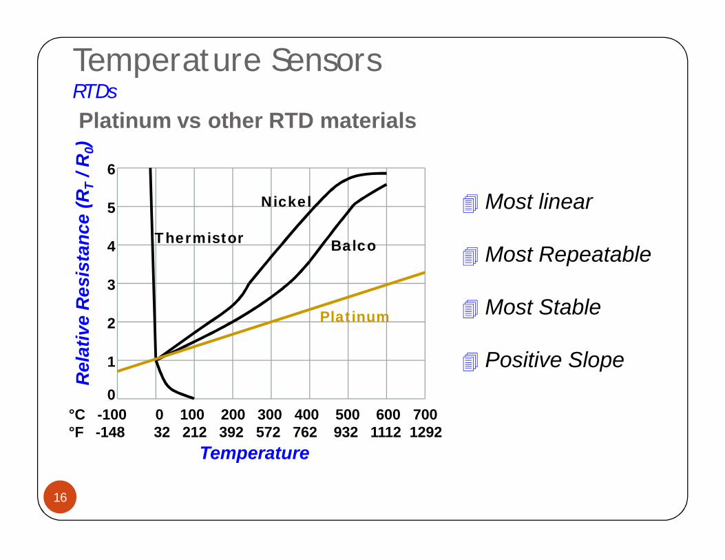
°C -100 0 100 200 300 400 500 600 700°F -148 32 212 392 572 762 932 1112 1292
Temperature
Rel
ativ
e R
esis
tanc
e (R
T/ R
0)
0
1
2
3
4
5
6
Platinum
Balco
Nickel
Thermistor
Most linear
Most Repeatable
Most Stable
Positive Slope
Platinum vs other RTD materials
Temperature SensorsRTDs
17
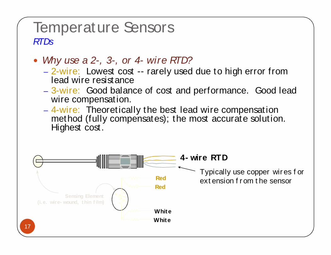
Why use a 2-, 3-, or 4- wire RTD?– 2-wire: Lowest cost -- rarely used due to high error from
lead wire resistance– 3-wire: Good balance of cost and performance. Good lead
wire compensation. – 4-wire: Theoretically the best lead wire compensation
method (fully compensates); the most accurate solution. Highest cost.
Sensing Element(i.e. wire-wound, thin film)
RedRed
White
Red
WhiteWhiteBlackGreenGreen
White
4-wire RTDTypically use copper wires for extension from the sensor
2-wire or 4-wire RTD ?
18
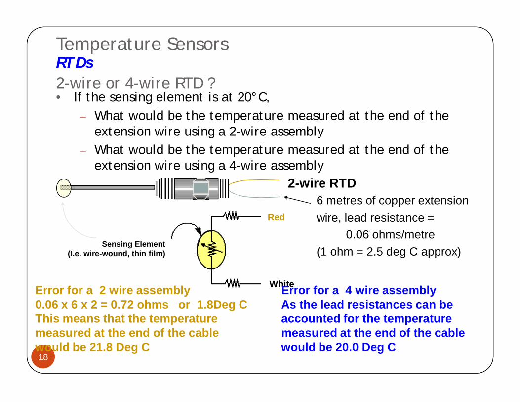
• If the sensing element is at 20°C, – What would be the temperature measured at the end of the
extension wire using a 2-wire assembly– What would be the temperature measured at the end of the
extension wire using a 4-wire assembly
Red
White
2-wire RTD6 metres of copper extensionwire, lead resistance =
0.06 ohms/metre(1 ohm = 2.5 deg C approx)
Sensing Element(I.e. wire-wound, thin film)
Temperature SensorsRTDs
Error for a 2 wire assembly0.06 x 6 x 2 = 0.72 ohms or 1.8Deg CThis means that the temperaturemeasured at the end of the cable would be 21.8 Deg C
Error for a 4 wire assemblyAs the lead resistances can be accounted for the temperature measured at the end of the cable would be 20.0 Deg C
Temperature SensorsRTDs
19
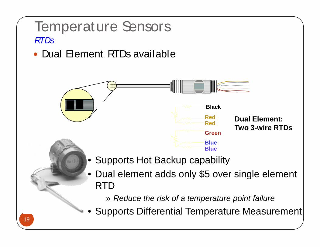
Dual Element RTDs available
• Supports Hot Backup capability• Dual element adds only $5 over single element
RTD» Reduce the risk of a temperature point failure
• Supports Differential Temperature Measurement
RedRed
White
Black
RedRedGreenBlueBlue
White
Dual Element:Two 3-wire RTDs
Temperature SensorsRTDs
20
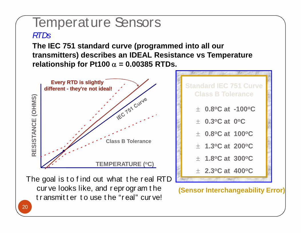
The IEC 751 standard curve (programmed into all our transmitters) describes an IDEAL Resistance vs Temperature relationship for Pt100 = 0.00385 RTDs.
TEMPERATURE (oC)
RES
ISTA
NC
E (O
HM
S)
Class B Tolerance
Standard IEC 751 CurveClass B Tolerance
Standard IEC 751 CurveClass B Tolerance
0.8oC at -100oC
0.3oC at 0oC
0.8oC at 100oC
1.3oC at 200oC
1.8oC at 300oC
2.3oC at 400oC
(Sensor Interchangeability Error)The goal is to find out what the real RTD
curve looks like, and reprogram the transmitter to use the “real” curve!
Every RTD is slightly different - they’re not ideal!
Every RTD is slightly different - they’re not ideal!
Temperature SensorsRTDs
21
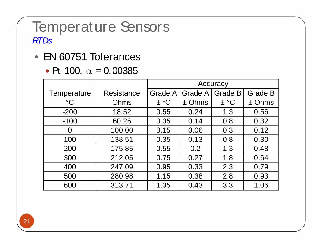
• EN 60751 Tolerances Pt 100, = 0.00385
AccuracyTemperature Resistance Grade A Grade A Grade B Grade B
°C Ohms ± °C ± Ohms ± °C ± Ohms-200 18.52 0.55 0.24 1.3 0.56-100 60.26 0.35 0.14 0.8 0.32
0 100.00 0.15 0.06 0.3 0.12100 138.51 0.35 0.13 0.8 0.30200 175.85 0.55 0.2 1.3 0.48300 212.05 0.75 0.27 1.8 0.64400 247.09 0.95 0.33 2.3 0.79500 280.98 1.15 0.38 2.8 0.93600 313.71 1.35 0.43 3.3 1.06

Temperature SensorsRTDs
22
Your customer is operating a process at 100°Cand is using a Platinum RTD...
What is the maximum error that will be introduced into the temperature measurement
from Sensor Interchangeability?
+/-0.35 deg C for Class A, +/-0.8 deg C for Class B
Fortunately, Sensor Interchangeability Error can be reduced or eliminated by Sensor Matching!
Quiz: - Find the Interchangeability Error

Temperature SensorsRTDs
23
What is RTD Calibration? The real RTD curve is found by “characterizing” an
RTD over a specific temperature range or point.» Temperature Range Characterization
Calibration certificate provided with sensor» Temperature Point Characterization
Calibration certificate provided with sensor
oC Ohms0.0 99.9971.0 100.382.0 100.773.0 101.16
Customer Receives RTD-specific Resistance vs. Temperature Chart:Data generated
(RTD “characterized”)
Temperature Bath- One temperature- Multiple temperatures
Temperature SensorsRTDs
24
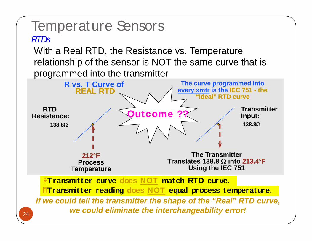
Transmitter reading does NOT equal process temperature.
212212°°FFProcess
Temperature
138.8W 138.8W
RTD Resistance:
TransmitterInput:
R vs. T Curve of REAL RTDREAL RTD
If we could tell the transmitter the shape of the “Real” RTD curve, we could eliminate the interchangeability error!
The curve programmed into every xmtr is the IEC 751 IEC 751 -- the the
“Ideal” RTD curve“Ideal” RTD curve
With a Real RTD, the Resistance vs. Temperature relationship of the sensor is NOT the same curve that is programmed into the transmitter
The TransmitterTranslates 138.8 W into 213.4213.4°°FF
Using the IEC 751
Transmitter curve does NOT match RTD curve.
Outcome ??Outcome ??
Temperature SensorsRTDs
25
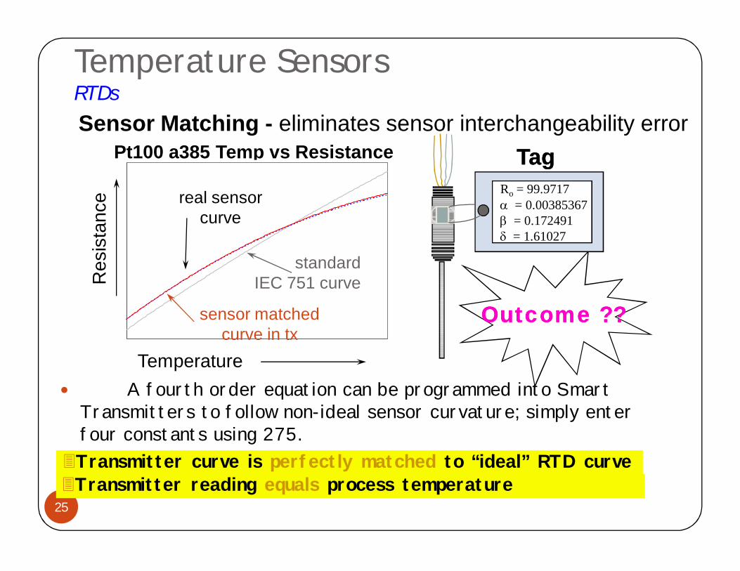
A fourth order equation can be programmed into Smart Transmitters to follow non-ideal sensor curvature; simply enter four constants using 275.
Pt100 a385 Temp vs Resistance
real sensorcurve
standard IEC 751 curve
sensor matchedcurve in tx
Res
ista
nce
Temperature
Transmitter reading equals process temperatureTransmitter curve is perfectly matched to “ideal” RTD curve
Outcome ??Outcome ??
Ro = 99.9717 = 0.00385367b = 0.172491d = 1.61027
TagTagSensor Matching - eliminates sensor interchangeability error
Temperature SensorsRTDs
26
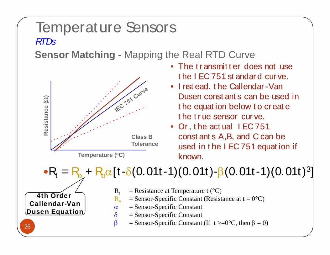
Rt = Ro + Ro[t-d(0.01t-1)(0.01t)-b(0.01t-1)(0.01t)3]Rt = Resistance at Temperature t (°C)Ro = Sensor-Specific Constant (Resistance at t = 0°C) = Sensor-Specific Constantd = Sensor-Specific Constantb = Sensor-Specific Constant (If t >=0°C, then b = 0)
Temperature (oC)
Res
ista
nce
(W)
Class B Tolerance
• The transmitter does not use the IEC 751 standard curve.
• Instead, the Callendar-Van Dusen constants can be used in the equation below to create the true sensor curve.
• Or, the actual IEC 751 constants A,B, and C can be used in the IEC 751 equation if known.
• The transmitter does not use the IEC 751 standard curve.
• Instead, the Callendar-Van Dusen constants can be used in the equation below to create the true sensor curve.
• Or, the actual IEC 751 constants A,B, and C can be used in the IEC 751 equation if known.
Sensor Matching - Mapping the Real RTD Curve
4th Order Callendar-Van
Dusen Equation
Temperature SensorsRTDs
27
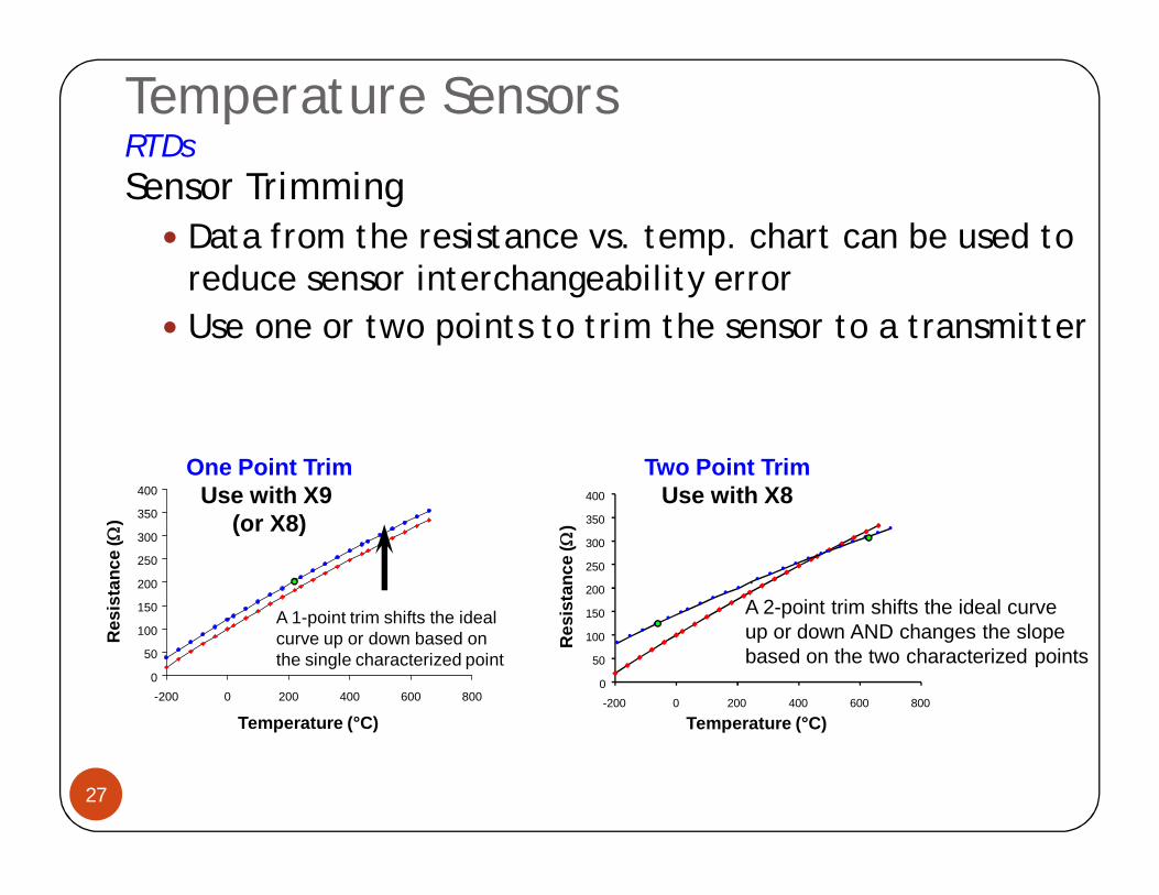
Sensor Trimming Data from the resistance vs. temp. chart can be used to
reduce sensor interchangeability error Use one or two points to trim the sensor to a transmitter
0
50
100
150
200
250
300
350
400
-200 0 200 400 600 800
A 1-point trim shifts the ideal curve up or down based on the single characterized point
Temperature (°C)
Res
ista
nce
(W)
A 2-point trim shifts the ideal curveup or down AND changes the slope based on the two characterized points
Temperature (°C)
Res
ista
nce
(W)
0
50
100
150
200
250
300
350
400
-200 0 200 400 600 800
One Point TrimUse with X9
(or X8)
Two Point TrimUse with X8
Temperature SensorsThermocouples
28
ProcessProcessTemperatureTemperature
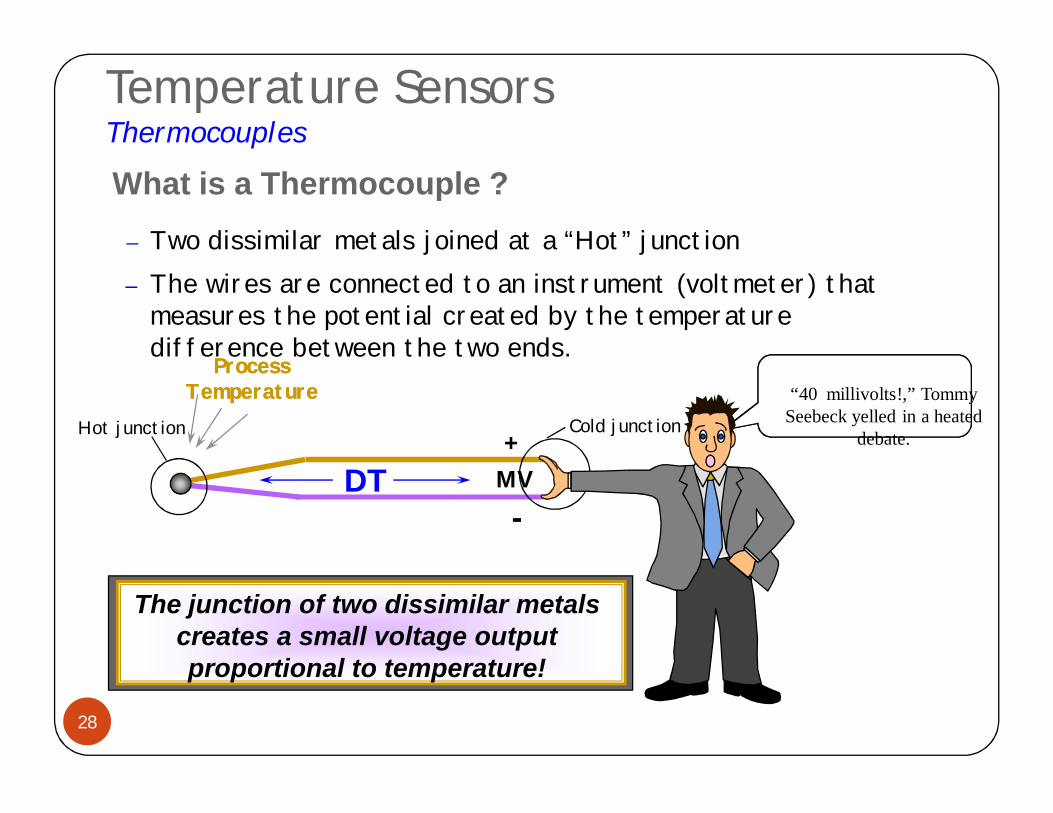
Hot junction
– Two dissimilar metals joined at a “Hot” junction
Cold junction+
-MV
– The wires are connected to an instrument (voltmeter) that measures the potential created by the temperature difference between the two ends.
DT
“40 millivolts!,” Tommy Seebeck yelled in a heated
debate.
The junction of two dissimilar metals creates a small voltage output proportional to temperature!
What is a Thermocouple ?
Temperature SensorsThermocouples
29
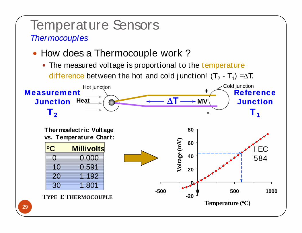
How does a Thermocouple work ? The measured voltage is proportional to the temperature temperature
difference difference between the hot and cold junction! (T2 - T1) =T.
+
-MVHeat
Hot junction Cold junction
oC Millivolts0 0.00010 0.59120 1.19230 1.801
Thermoelectric Voltagevs. Temperature Chart:
TYPE E THERMOCOUPLE
DT
-20
0
20
40
60
80
-500 0 500 1000
Volta
ge (m
V)
Temperature (oC)
IEC584
Measurement Measurement JunctionJunction
TT22
Reference Reference JunctionJunction
TT11
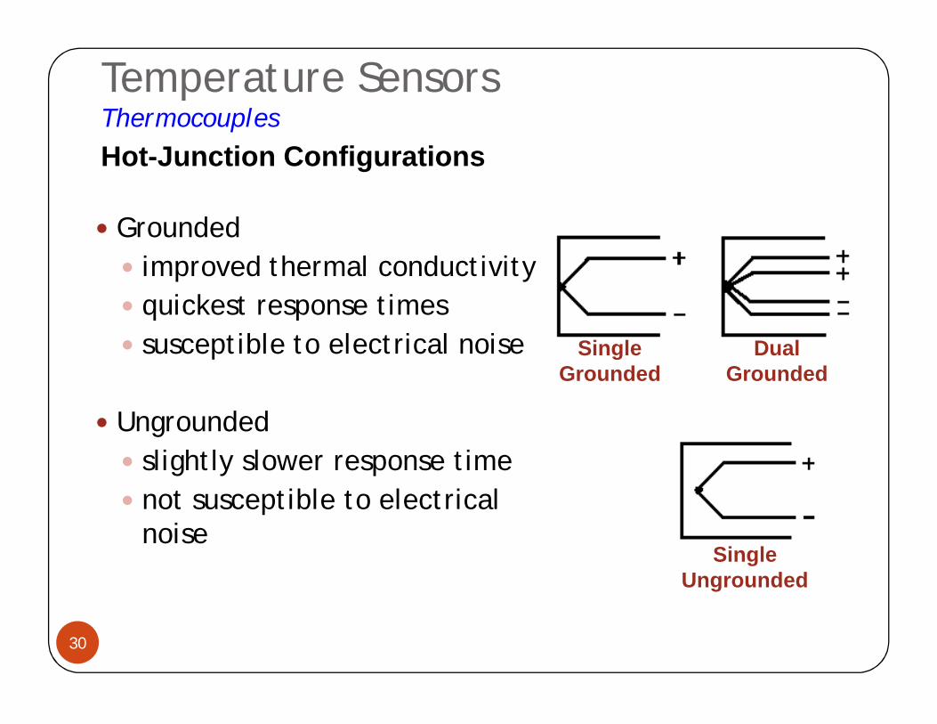
Temperature SensorsThermocouples
30
Grounded improved thermal conductivity quickest response times susceptible to electrical noise
Ungrounded slightly slower response time not susceptible to electrical
noise
Single Grounded
Dual Grounded
Single Ungrounded
Hot-Junction Configurations
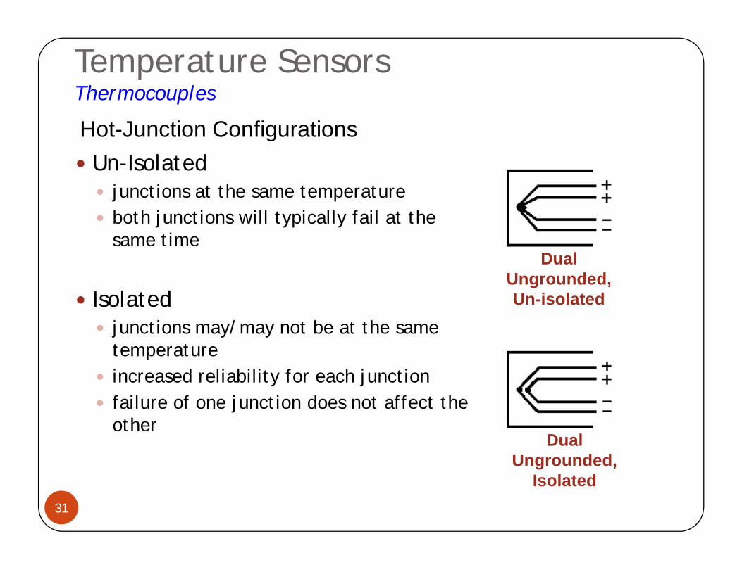
Temperature SensorsThermocouples
31
Un-Isolated junctions at the same temperature both junctions will typically fail at the
same time
Isolated junctions may/may not be at the same
temperature increased reliability for each junction failure of one junction does not affect the
other
Hot-Junction Configurations
Dual Ungrounded, Un-isolated
Dual Ungrounded,
Isolated
Temperature SensorsThermocouples
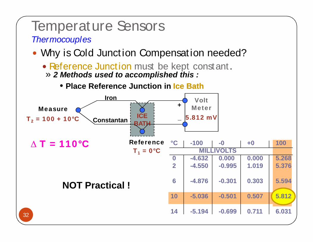
32
Why is Cold Junction Compensation needed? Reference Junction Reference Junction must be kept constant.
ICEBATH
T1 = 0°C
Measure
Reference
Iron
Constantan
+
_
VoltMeter
T2 = 100 + 10°C 5.812 mV
» 2 Methods used to accomplished this :• Place Reference Junction in Ice BathIce Bath
NOT Practical !
°C -100 -0 +0 100MILLIVOLTS
0 -4.632 0.000 0.000 5.2682 -4.550 -0.995 1.019 5.376
6 -4.876 -0.301 0.303 5.594
10 -5.036 -0.501 0.507 5.812
14 -5.194 -0.699 0.711 6.031
T = 110T = 110°°CC
Temperature SensorsThermocouples
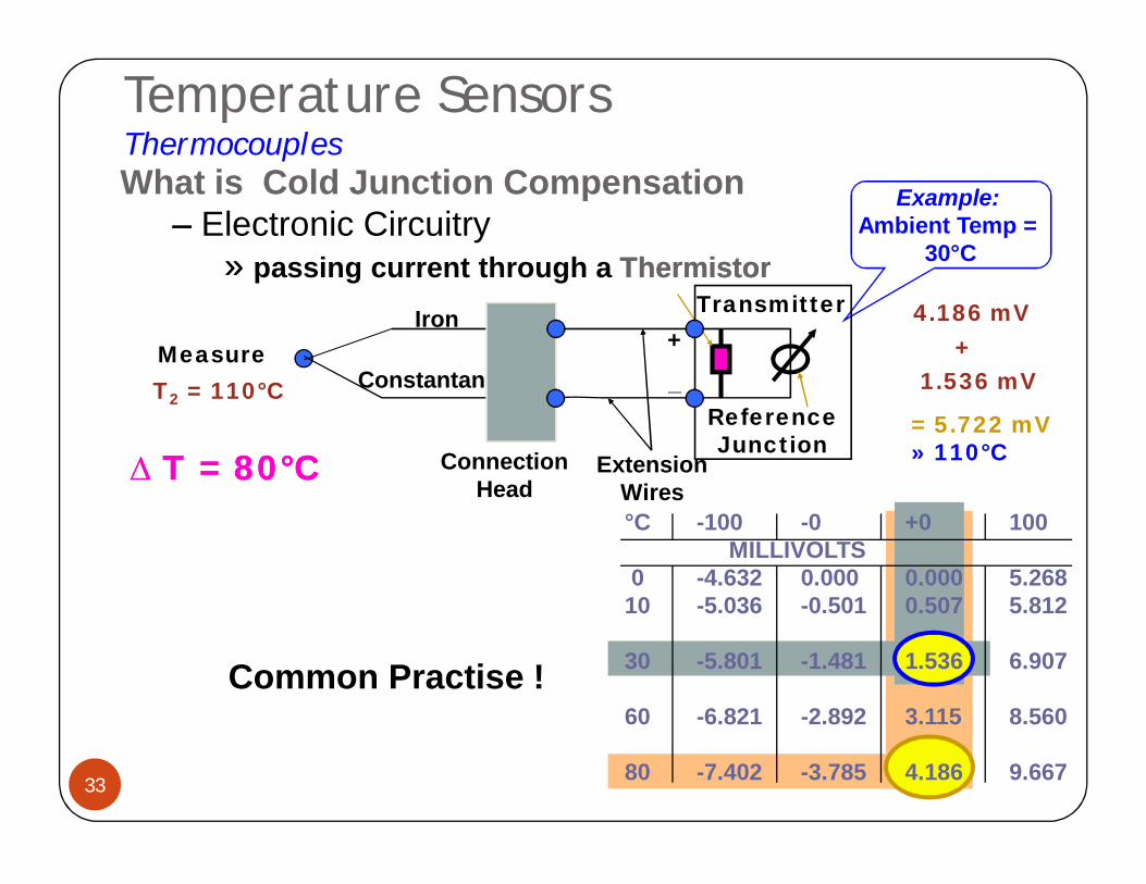
33
Measure
ReferenceJunction
Iron
Constantan+
_
Transmitter
T2 = 110°C
4.186 mV
What is Cold Junction Compensation–– Electronic Circuitry
»» passing current through a ThermistorThermistor
Common Practise !
T = 80T = 80°°CC Connection Head
Extension Wires
Example:Ambient Temp =
30°C
°C -100 -0 +0 100MILLIVOLTS
0 -4.632 0.000 0.000 5.26810 -5.036 -0.501 0.507 5.812
30 -5.801 -1.481 1.536 6.907
60 -6.821 -2.892 3.115 8.560
80 -7.402 -3.785 4.186 9.667
+1.536 mV
= 5.722 mV» 110°C
Temperature SensorsThermocouples
34
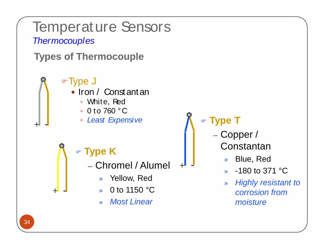
Type J Iron / Constantan White, Red 0 to 760 °C Least Expensive
Types of Thermocouple
Type K– Chromel / Alumel
» Yellow, Red» 0 to 1150 °C» Most Linear
Type T– Copper /
Constantan» Blue, Red» -180 to 371 °C» Highly resistant to
corrosion from moisture
+ -
+ -
+ -
Temperature SensorsThermocouples
35
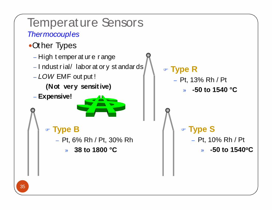
Other Types
Type B– Pt, 6% Rh / Pt, 30% Rh
» 38 to 1800 °C
Type S– Pt, 10% Rh / Pt
» -50 to 1540oC
Type R– Pt, 13% Rh / Pt
» -50 to 1540 °C
– High temperature range– Industrial/ laboratory standards– LOW EMF output!
(Not very sensitive)– Expensive!
Temperature SensorsThermocouples
36
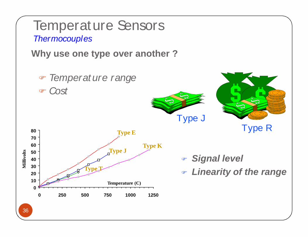
Temperature range Cost
Why use one type over another ?
01020304050607080
0 250 500 750 1000 1250
Type E
Type KType J
Type T Signal level Linearity of the range
Mill
ivol
ts
Temperature (C)
Type JType R
Temperature SensorsThermocouples
37
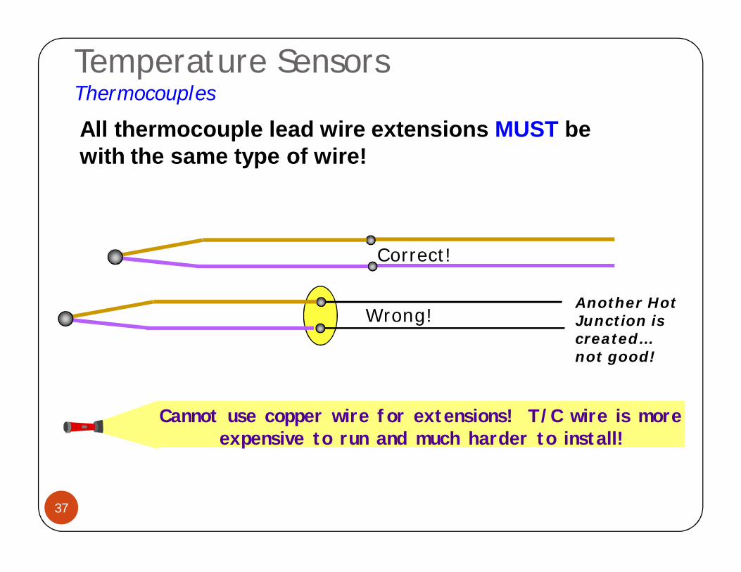
Correct!
Wrong!
All thermocouple lead wire extensions MUST be with the same type of wire!
Another Hot Junction is created… not good!
Cannot use copper wire for extensions! T/C wire is more expensive to run and much harder to install!
Temperature SensorsComparison
38
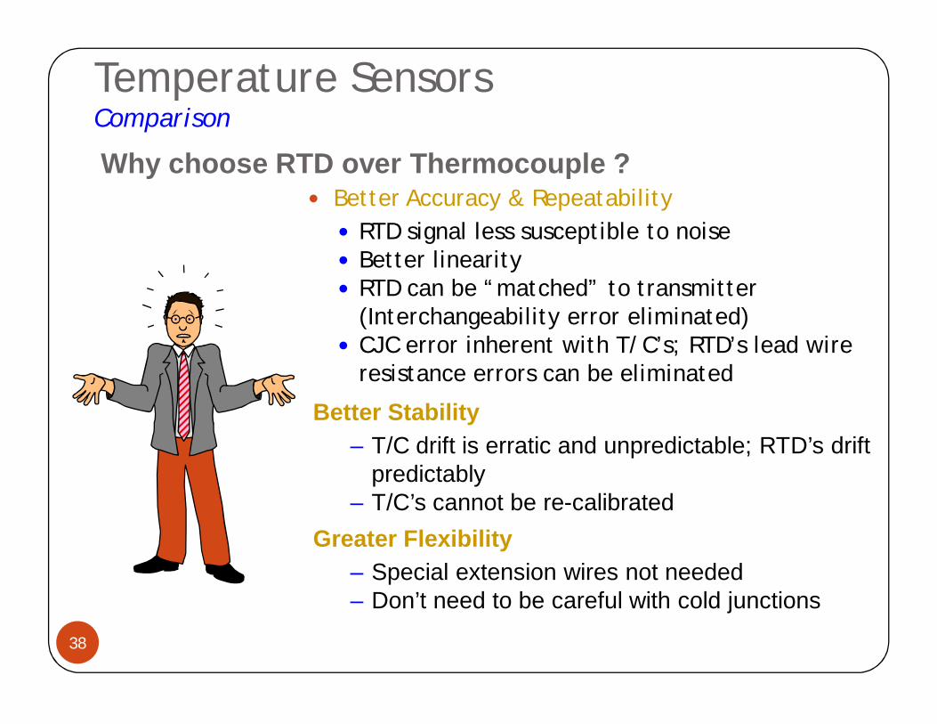
Better Accuracy & Repeatability RTD signal less susceptible to noise Better linearity RTD can be “matched” to transmitter
(Interchangeability error eliminated) CJC error inherent with T/C’s; RTD’s lead wire
resistance errors can be eliminated
Why choose RTD over Thermocouple ?
Better Stability– T/C drift is erratic and unpredictable; RTD’s drift
predictably– T/C’s cannot be re-calibrated
Greater Flexibility– Special extension wires not needed– Don’t need to be careful with cold junctions
Temperature SensorsComparison
39
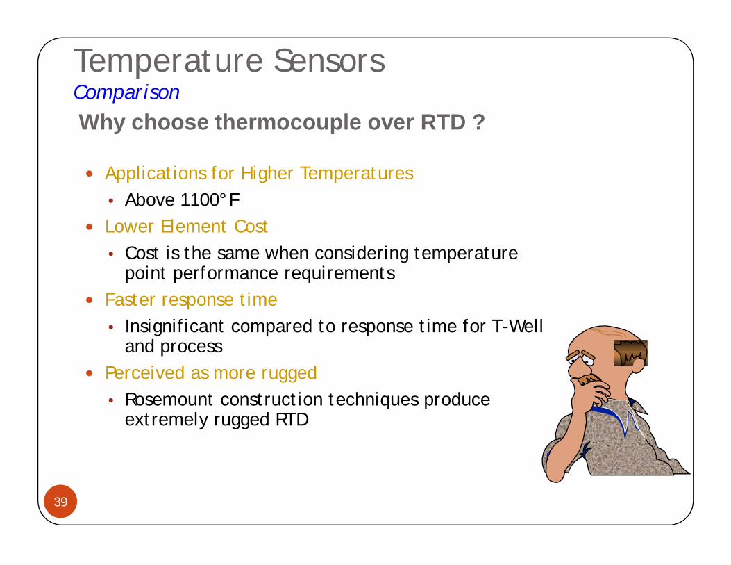
Applications for Higher Temperatures• Above 1100°F
Lower Element Cost • Cost is the same when considering temperature
point performance requirements Faster response time
• Insignificant compared to response time for T-Well and process
Perceived as more rugged• Rosemount construction techniques produce
extremely rugged RTD
Why choose thermocouple over RTD ?
40
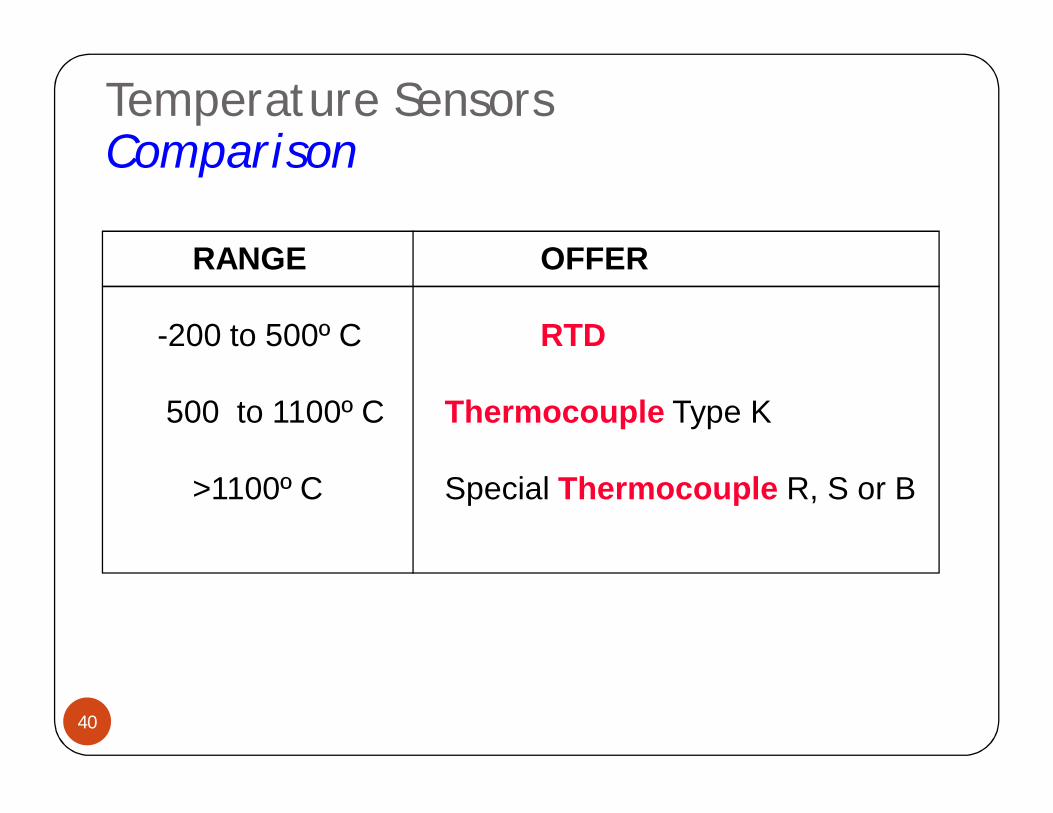
RANGE OFFER
-200 to 500º C RTD
500 to 1100º C Thermocouple Type K
>1100º C Special Thermocouple R, S or B
Temperature SensorsComparison