temporal coherency for video tone mapping - ece.ubc.ca
TRANSCRIPT
Temporal Coherency for Video Tone Mapping
Ronan Boitarda,b, Kadi Bouatouchb, Remi Cozotb, Dominique Thoreaua and Adrien Grusonb
aTechnicolor R&D France, 1 av. Belle Fontaine, Rennes, France;bIRISA, 263 Avenue du General Leclerc, Rennes, France
ABSTRACT
Tone Mapping Operators (TMOs) aim at converting real world high dynamic range (HDR) images captured withHDR cameras, into low dynamic range (LDR) images that can be displayed on LDR displays. Several TMOshave been proposed over the last decade, from the simple global mapping to the more complex one simulating thehuman vision system. While these solutions work generally well for still pictures, they are usually less efficient forvideo sequences as they are source of visual artifacts. Only few of them can be adapted to cope with a sequenceof images. In this paper we present a major problem that a static TMO usually encounters while dealing withvideo sequences, namely the temporal coherency. Indeed, as each tone mapper deals with each frame separately,no temporal coherency is taken into account and hence the results can be quite disturbing for high varyingdynamics in a video. We propose a temporal coherency algorithm that is designed to analyze a video as a whole,and from its characteristics adapts each tone mapped frame of a sequence in order to preserve the temporalcoherency. This temporal coherency algorithm has been tested on a set of real as well as Computer GraphicsImage (CGI) content and put in competition with several algorithms that are designed to be time-dependent.Results show that temporal coherency preserves the overall contrast in a sequence of images. Furthermore, thistechnique is applicable to any TMO as it is a post-processing that only depends on the used TMO.
Keywords: Video Tone Mapping, HDR Video, Temporal Coherency
1. INTRODUCTION
With the development of sensor technology, it is now possible to capture more information than can be dis-played. While some emerging technologies are capable of displaying broader luminance ranges, they are stillquite expensive and will not be available on the customer market soon. That is why some operations are stillneeded to convert High Dynamic Range (HDR) contents to Low Dynamic Range (LDR) ones. These operationsare performed using Tone Mapping Operators (TMOs), also called Tone Reproducers. Technology regarding thetone mapping of still pictures has been thoroughly explored and several satisfying solutions1 have been designed.Furthermore, these operators have various goals and their results can be quite different. Nevertheless, most ofthe existing operators are not designed to handle video sequences.
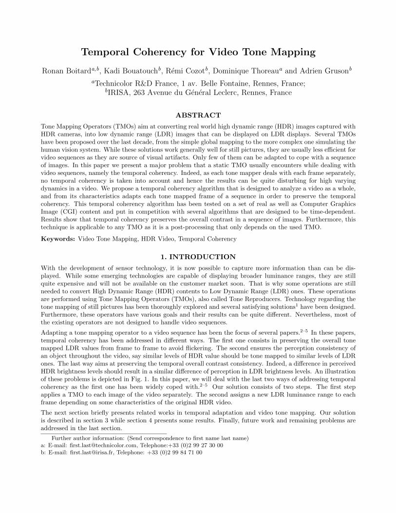
Adapting a tone mapping operator to a video sequence has been the focus of several papers.2–5 In these papers,temporal coherency has been addressed in different ways. The first one consists in preserving the overall tonemapped LDR values from frame to frame to avoid flickering. The second ensures the perception consistency ofan object throughout the video, say similar levels of HDR value should be tone mapped to similar levels of LDRones. The last way aims at preserving the temporal overall contrast consistency. Indeed, a difference in perceivedHDR brightness levels should result in a similar difference of perception in LDR brightness levels. An illustrationof these problems is depicted in Fig. 1. In this paper, we will deal with the last two ways of addressing temporalcoherency as the first one has been widely coped with.2–5 Our solution consists of two steps. The first stepapplies a TMO to each image of the video separately. The second assigns a new LDR luminance range to eachframe depending on some characteristics of the original HDR video.
The next section briefly presents related works in temporal adaptation and video tone mapping. Our solutionis described in section 3 while section 4 presents some results. Finally, future work and remaining problems areaddressed in the last section.
Further author information: (Send correspondence to first name last name)a: E-mail: [email protected], Telephone:+33 (0)2 99 27 30 00b: E-mail: [email protected], Telephone: +33 (0)2 99 84 71 00
(a) HDR False Color(b) Frame with sun (c) Frame without sun
Figure 1: Illustration of lack of temporal coherency in video tone mapping. On the false color representation (a),red represents the maximum HDR value of the video while blue its minimum. Both frames have the same HDRvalues between similar regions. However the scene (c) appears a lot brighter than the scene (b). Furthermore,the perception of the landscape is different between the two frames.
2. RELATED WORK IN VIDEO TONE MAPPING
Tone mapping aims at converting HDR luminance values (Lw) into LDR luma values (Ld). Luma is the weightedsum of gamma-compressed R’G’B’ components of a color video. The 3 original HDR color channels RGB arescaled by Ld/Lw so as to preserve both the hue and the saturation in the tone mapped LDR image. The aims ofTMOs can be quite different since they depend on the targeted applications. While our approach adapts easilyto any TMO, in this work, similarly to other publications,3,4 we decided to build our solution upon Reinhard’sTMO, called Photographic Tone Reproduction (PTR).6
In this section, the PTR algorithm is first introduced, before describing two methods that adapt this TMO tovideo tone mapping. Afterwards, two other TMOs designed for video tone mapping are presented. Finally, issuessolved by these techniques are listed as well as the problems still unsolved.
2.1 Photographic Tone Reproduction
The PTR algorithm is based on photographic techniques and allows to choose the exposure of the tone mappedimage. More precisely, this operator relies on the zonal system designed by Adams.7 This exposure is used tocalibrate the input data (Equation (2)) depending on the key values of the image to be tone mapped. The keyvalue of a scene, κ, is a subjective indication of its overall brightness. It is given by Equation (1):
κ = exp
(1
N·
N∑n=1
log(δ + Lnw)
), (1)
Ls =a
κ· Lw , (2)
where a is the chosen exposure, δ is a small value to avoid singularity, Lw is the HDR luminance and Ls thescaled luminance. N is the number of pixels in the image. The tone mapping operation consists in using a tonemap curve (sigmoid function) given by Equation (3):
Ld =Ls
1 + Ls·(
1 +Ls
L2white
), (3)
where Lwhite is used to burn out areas with a high luminance value and Ld is the LDR luma. Two parameters(a and Lwhite) are then necessary to compute the TMO results. For the sake of simplicity, these parameters arefixed for every sequence to a = 18% and Lwhite = 2 · Lmax.
Although this TMO has been well rated in several evaluations,8–10 it is not designed to work properly for videosequences. Indeed, if the key values change, the tone map curve also changes, resulting in different mappingsfor similar HDR luminance levels in successive frames, which is source of flickering. In the following section, twosolutions are presented to avoid this flickering.
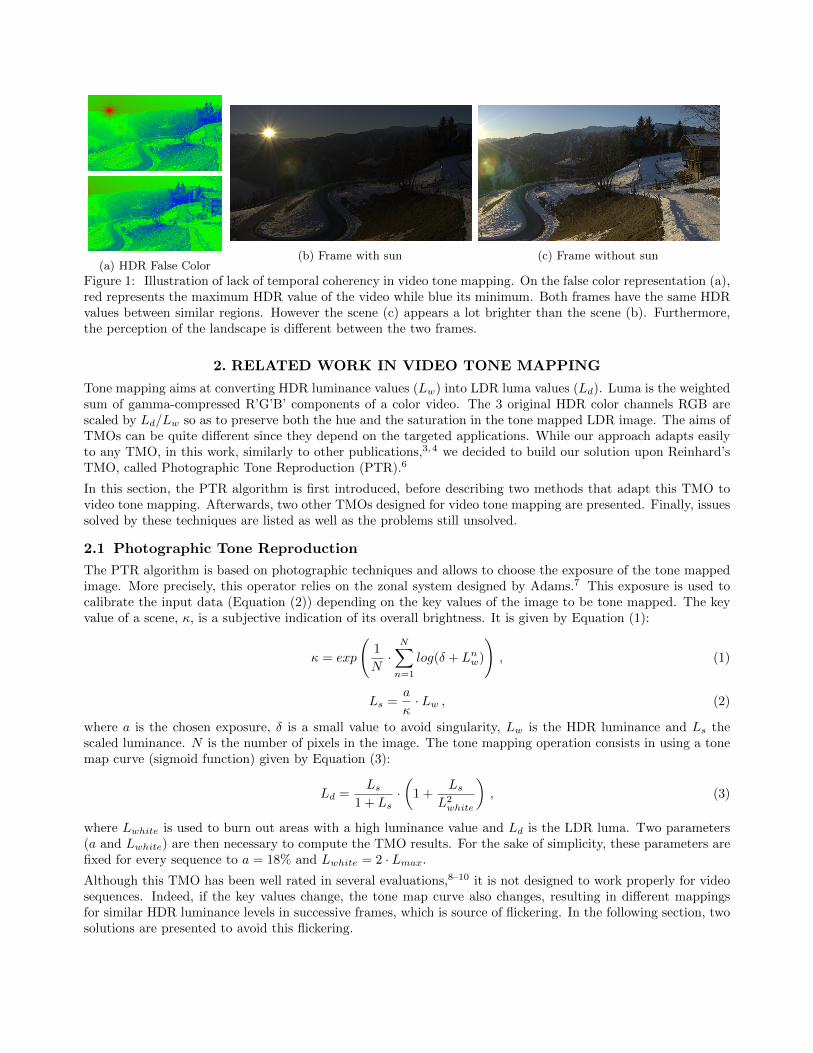
(a) Sun Sequence (b) Walking Ticks
Figure 2: Evolution of the frame key value computed for every frame of two video sequences. On plot (a), anoffset is added to avoid an overlap between the curves, the smoothing effect of both techniques are compared toReinhard’s et al. technique. Kang’s et al. technique smoothes and propagates a change of value while Ramsey’set al. technique only smoothes it. On plot (b), Ramsey’s et al. improvement reduces the temporal shiftingcompared to Kang’s et al. when sharp variations occurs.
2.2 Toward Video Tone Mapping
Kang et al.3 proposed a method based on Reinhard’s operator to reduce the flickering effect. Each image is tonemapped independently using a key value depending on a set of previous frames. More precisely, this key valueis computed using Equation (1) with N the number of pixels of this set augmented with the one of the currentimage. As a consequence, this method smoothes abrupt variations of the frame key value throughout the videosequence. This technique is capable of reducing flickering for sequences with slow illumination variations. It isa first step toward temporal coherency as the processing of each frame depends on its previous ones.
However, for high variations, this technique fails because it considers a fixed number of previous frames. That iswhy, Ramsey et al.4 proposed a method that adapts dynamically this number. The adaptation process dependson the variation of the current frame key value and that of the previous frame. Moreover, the adaptation discardsoutliers using a min/max threshold. This solution performs better than that of Kang’s et al. for a wider rangeof video sequences. The computed key value for both of these techniques and the PTR algorithm is plotted inFig. 2.
2.3 Display Adaptive Tone Mapping
Mantiuk et al.5 proposed a TMO that provides the least perceptually distorted LDR picture on a targeted display.Similarly to Tumblin and Rushmeier,11 whose operator’s goal is to ensure that the scene and display brightnessesmatch, Mantiuk et al. compare the visual response of the Human Visual System (HVS) to the display-adaptedLDR image with that of the original HDR image. The minimization of the residual error between these responsesresults in a piece-wise linear tone map curve. However, this minimization is computed on a per frame basis andconsequently inherits all the problems related to video tone mapping.
To solve this issue, the authors propose a temporal adaptation using a low-pass filter applied to the nodes ofthe piece-wise tone curve. Similarly to the previous solutions,3,4 the tone map curve is smoothed. Nevertheless,this solution’s drawbacks are similar to those of Kang’s et al. technique. In addition, an optimization performedon a per frame basis is quite different from an optimization applied to the whole sequence. Consequently theminimization of the perceptual distortion is not preserved during the temporal adaptation.
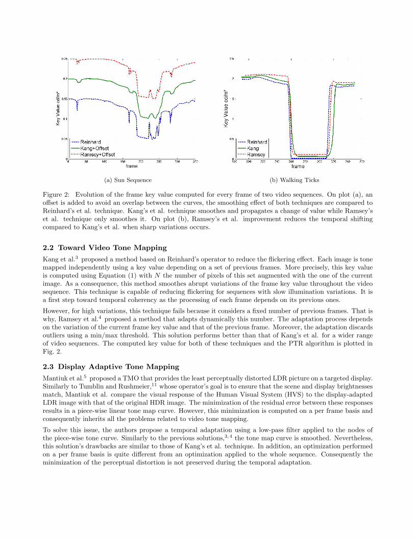
Figure 3: Change of perception of an object when the TMO processes the frames independently. The constantHDR luminance of an object (green line) is tone mapped to high varying LDR luma values (green dashed line).The highly changing maximum HDR luminance value of every frame (orange line) is tone mapped to the sameLDR luma level (orange dashed line).
2.4 Time Dependent Visual Adaptation Tone Mapping
Pattanaik et al.12 designed a TMO called Time Dependent Visual Adaptation (TDVA). The aim of this operatoris to simulate the adaptation of the HVS when a change of illumination occurs. Similarly to other HVS basedoperators,13,14 this TMO simulates both cone and rod photoreceptor responses using Hunt’s model:15
Rrod = BrodLnrod
Lnrod + σn
rod
, Rcone = BconeLncone
Lncone + σn
cone
, (4)
where R is the response to the HDR luminance L, n is a sensitivity constant and both B and σ are determineddepending on the overall scene luminance. The combination of these responses is adapted to the targeted displayrange through an appearance/inverse appearance model. Finally, those responses are inverted to compute thetone mapped LDR luma.
While this TMO is called time-dependent, it was not designed for video sequences. It only simulates the timeneeded for the eye to adapt to a change of illumination condition, say when the photoreceptors are fully adapted.This adaptation time is modeled by exponential decay functions. This TMO computes each frame separatelywhile taking into account the adaptation state of the previous frame.
2.5 Open Issues
As seen in the previous subsections, the first three proposed methods3–5 aim at reducing the flickering due tochanges in the tone map curve throughout subsequent frames. Their solutions smooth the evolution of thesecurves either by adapting the key value to several frames3,4 or by filtering the tone map curve itself.5 On theother hand, the last method12 simulates the behavior of the HVS during the transition between two fully adaptedstates. However, this method also reduces the flickering effect, as it prevents the variables, which control thetone map curve, from evolving too quickly.
While effectively reducing the flickering, these techniques do not solve all the problems inherent in video tonemapping such as the perception consistency of an object and the preservation of the overall temporal brightness(subjective value relative to luminance). The contribution of this paper is to address these two problems.
To ensure that the perception of an object is coherent throughout a video is our first aim. However, a TMOprocesses each frame separately and without information of the previous/next state of an object. That is why,an object with constant HDR luminance level throughout the whole video is tone mapped to several differentLDR levels. This problem is illustrated in Fig. 3 where the green line represents an object with constant HDRluminance value over time whereas its associated tone mapped value varies.
Our second aim is to preserve the temporal brightness coherency. As a static TMO uses to the best the availabledisplay range, each frame is tone mapped to the best brightness level independently of the whole video sequence.Consequently, relative temporal HDR brightness information is not preserved during the course of the tonemapping process. In addition, the maximum HDR luminance value of each frame is tone mapped to the maximumLDR luma value, meaning that different HDR luminance values are tone mapped to the same LDR value. Fig. 3illustrates this problem by the orange line which highly varies for the HDR sequence but is practically constantin the LDR sequence. Consequently, relative HDR brightness levels through subsequent frames are not preservedin the LDR frames. In the next section, we propose solutions to solve the two above mentioned problems.
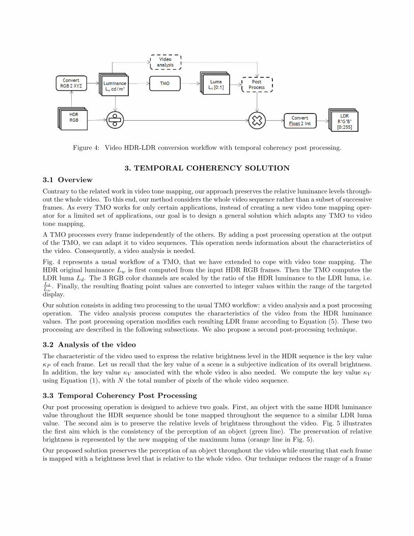
Figure 4: Video HDR-LDR conversion workflow with temporal coherency post processing.
3. TEMPORAL COHERENCY SOLUTION
3.1 Overview
Contrary to the related work in video tone mapping, our approach preserves the relative luminance levels through-out the whole video. To this end, our method considers the whole video sequence rather than a subset of successiveframes. As every TMO works for only certain applications, instead of creating a new video tone mapping oper-ator for a limited set of applications, our goal is to design a general solution which adapts any TMO to videotone mapping.
A TMO processes every frame independently of the others. By adding a post processing operation at the outputof the TMO, we can adapt it to video sequences. This operation needs information about the characteristics ofthe video. Consequently, a video analysis is needed.
Fig. 4 represents a usual workflow of a TMO, that we have extended to cope with video tone mapping. TheHDR original luminance Lw is first computed from the input HDR RGB frames. Then the TMO computes theLDR luma Ld. The 3 RGB color channels are scaled by the ratio of the HDR luminance to the LDR luma, i.e.Ld
Lw. Finally, the resulting floating point values are converted to integer values within the range of the targeted
display.
Our solution consists in adding two processing to the usual TMO workflow: a video analysis and a post processingoperation. The video analysis process computes the characteristics of the video from the HDR luminancevalues. The post processing operation modifies each resulting LDR frame according to Equation (5). These twoprocessing are described in the following subsections. We also propose a second post-processing technique.
3.2 Analysis of the video
The characteristic of the video used to express the relative brightness level in the HDR sequence is the key valueκP of each frame. Let us recall that the key value of a scene is a subjective indication of its overall brightness.In addition, the key value κV associated with the whole video is also needed. We compute the key value κVusing Equation (1), with N the total number of pixels of the whole video sequence.
3.3 Temporal Coherency Post Processing
Our post processing operation is designed to achieve two goals. First, an object with the same HDR luminancevalue throughout the HDR sequence should be tone mapped throughout the sequence to a similar LDR lumavalue. The second aim is to preserve the relative levels of brightness throughout the video. Fig. 5 illustratesthe first aim which is the consistency of the perception of an object (green line). The preservation of relativebrightness is represented by the new mapping of the maximum luma (orange line in Fig. 5).
Our proposed solution preserves the perception of an object throughout the video while ensuring that each frameis mapped with a brightness level that is relative to the whole video. Our technique reduces the range of a frame

Figure 5: Post processing. The LDR luma is the output of the TMO, see Fig. 3. The object luma (green line)variations have been reduced allowing a perception of the object through time stable. The maximum LDR luma(orange line) is reduce to a smaller range in order to preserve temporal brightness coherency.
to preserve the relative brightnesses. This reduction is performed using a scaling function (Equation (5)) whoseshape is defined by the key video value κV and the current frame key value κF :
L′d =
κFκV + κF
· Ld , (5)
where L′d is the post processed LDR luma value and Ld is the output of the TMO. However, in the case of low
scaling value, the range is too small to represent a scene. To cope with this problem, we modify the slope of thescaling function and add an user defined offset MinScale set by the user as shown in Equation (6):
L′d =
(MinScale+ (1 −MinScale) · κF
κV + κF
)· Ld . (6)
This method performs well regarding the two aforementioned aims. However, the proposed scaling functionworks only for Reinhard’s technique and its derivative. To adapt our solution to Kang’s et al. or Ramsey’s et al.techniques, we just need to compute new κF and κV values. However, adapting our method to another TMO isnot straightforward but possible with some changes in the scaling function.
In case the preservation of the perception of an object is not considered, we propose in the next subsection,another method which works for every TMO.
3.4 Relative Brightness Preservation with any TMO
We want to devise a technique which adapts to any TMO. To this end, we propose a method which ignores thepreservation of object perception but ensures the temporal brightness coherency between frames of the sequence.This solution works for any TMO.
Similarly to Tumblin and Rushmeier,11 whose operator’s goal is to ensure that the scene and display brightnessesmatch, in our method the relative difference of brightness between frames is preserved. To this end, the LDRluma Ld is modified to satisfy the following equation:
κHDRF
κHDRF,max
=κLDRF
κLDRF,max
, (7)
where κHDRF is the current HDR frame key value and κHDR
F,max is the maximum frame key value of the video. Thenew scaling function is defined by:
L′d = Ld ·
κHDRP · κLDR
P,max
κHDRP,max · κLDR
P
(8)
where the κP are computed using Equation (1) and L′d is the post-processed LDR luma. This solution preserves
the relative HDR brightness levels in the LDR tone map results. Similarly to the previous section, where lowscale ratio results in artifacts, we use the modifications added in Equation (6).
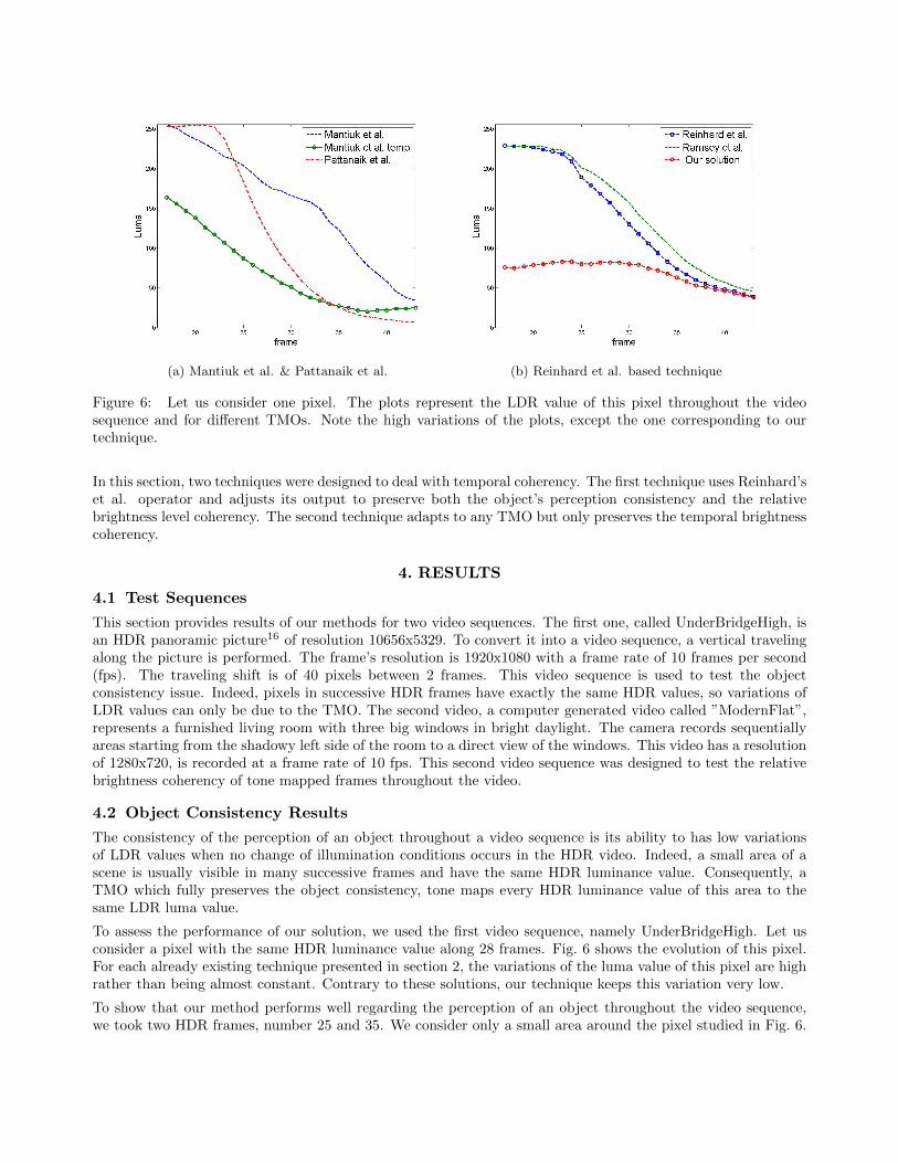
(a) Mantiuk et al. & Pattanaik et al. (b) Reinhard et al. based technique
Figure 6: Let us consider one pixel. The plots represent the LDR value of this pixel throughout the videosequence and for different TMOs. Note the high variations of the plots, except the one corresponding to ourtechnique.
In this section, two techniques were designed to deal with temporal coherency. The first technique uses Reinhard’set al. operator and adjusts its output to preserve both the object’s perception consistency and the relativebrightness level coherency. The second technique adapts to any TMO but only preserves the temporal brightnesscoherency.
4. RESULTS
4.1 Test Sequences
This section provides results of our methods for two video sequences. The first one, called UnderBridgeHigh, isan HDR panoramic picture16 of resolution 10656x5329. To convert it into a video sequence, a vertical travelingalong the picture is performed. The frame’s resolution is 1920x1080 with a frame rate of 10 frames per second(fps). The traveling shift is of 40 pixels between 2 frames. This video sequence is used to test the objectconsistency issue. Indeed, pixels in successive HDR frames have exactly the same HDR values, so variations ofLDR values can only be due to the TMO. The second video, a computer generated video called ”ModernFlat”,represents a furnished living room with three big windows in bright daylight. The camera records sequentiallyareas starting from the shadowy left side of the room to a direct view of the windows. This video has a resolutionof 1280x720, is recorded at a frame rate of 10 fps. This second video sequence was designed to test the relativebrightness coherency of tone mapped frames throughout the video.
4.2 Object Consistency Results
The consistency of the perception of an object throughout a video sequence is its ability to has low variationsof LDR values when no change of illumination conditions occurs in the HDR video. Indeed, a small area of ascene is usually visible in many successive frames and have the same HDR luminance value. Consequently, aTMO which fully preserves the object consistency, tone maps every HDR luminance value of this area to thesame LDR luma value.
To assess the performance of our solution, we used the first video sequence, namely UnderBridgeHigh. Let usconsider a pixel with the same HDR luminance value along 28 frames. Fig. 6 shows the evolution of this pixel.For each already existing technique presented in section 2, the variations of the luma value of this pixel are highrather than being almost constant. Contrary to these solutions, our technique keeps this variation very low.
To show that our method performs well regarding the perception of an object throughout the video sequence,we took two HDR frames, number 25 and 35. We consider only a small area around the pixel studied in Fig. 6.
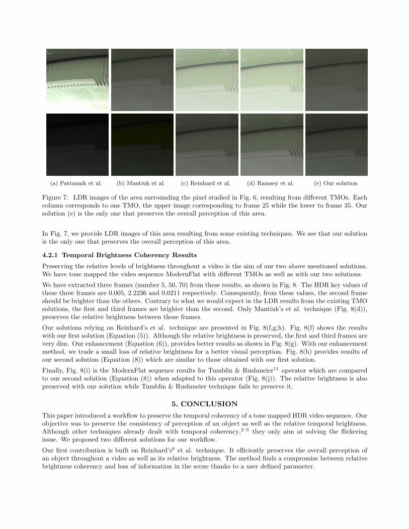
(a) Pattanaik et al. (b) Mantiuk et al. (c) Reinhard et al. (d) Ramsey et al. (e) Our solution
Figure 7: LDR images of the area surrounding the pixel studied in Fig. 6, resulting from different TMOs. Eachcolumn corresponds to one TMO, the upper image corresponding to frame 25 while the lower to frame 35. Oursolution (e) is the only one that preserves the overall perception of this area.
In Fig. 7, we provide LDR images of this area resulting from some existing techniques. We see that our solutionis the only one that preserves the overall perception of this area.
4.2.1 Temporal Brightness Coherency Results
Preserving the relative levels of brightness throughout a video is the aim of our two above mentioned solutions.We have tone mapped the video sequence ModernFlat with different TMOs as well as with our two solutions.
We have extracted three frames (number 5, 50, 70) from these results, as shown in Fig. 8. The HDR key values ofthese three frames are 0.005, 2.2236 and 0.0211 respectively. Consequently, from these values, the second frameshould be brighter than the others. Contrary to what we would expect in the LDR results from the existing TMOsolutions, the first and third frames are brighter than the second. Only Mantiuk’s et al. technique (Fig. 8(d)),preserves the relative brightness between those frames.
Our solutions relying on Reinhard’s et al. technique are presented in Fig. 8(f,g,h). Fig. 8(f) shows the resultswith our first solution (Equation (5)). Although the relative brightness is preserved, the first and third frames arevery dim. Our enhancement (Equation (6)), provides better results as shown in Fig. 8(g). With our enhancementmethod, we trade a small loss of relative brightness for a better visual perception. Fig. 8(h) provides results ofour second solution (Equation (8)) which are similar to those obtained with our first solution.
Finally, Fig. 8(i) is the ModernFlat sequence results for Tumblin & Rushmeier11 operator which are comparedto our second solution (Equation (8)) when adapted to this operator (Fig. 8(j)). The relative brightness is alsopreserved with our solution while Tumblin & Rushmeier technique fails to preserve it.
5. CONCLUSION
This paper introduced a workflow to preserve the temporal coherency of a tone mapped HDR video sequence. Ourobjective was to preserve the consistency of perception of an object as well as the relative temporal brightness.Although other techniques already dealt with temporal coherency,3–5 they only aim at solving the flickeringissue. We proposed two different solutions for our workflow.
Our first contribution is built on Reinhard’s6 et al. technique. It efficiently preserves the overall perception ofan object throughout a video as well as its relative brightness. The method finds a compromise between relativebrightness coherency and loss of information in the scene thanks to a user defined parameter.
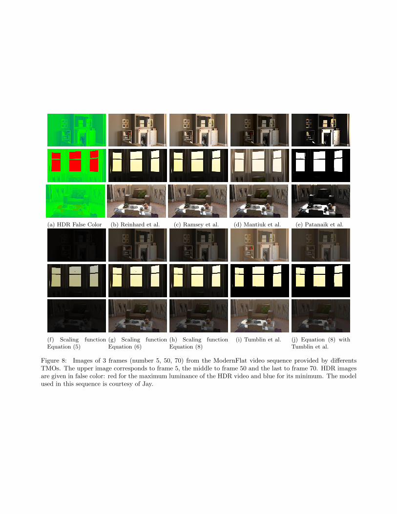
(a) HDR False Color (b) Reinhard et al. (c) Ramsey et al. (d) Mantiuk et al. (e) Patanaik et al.
(f) Scaling functionEquation (5)
(g) Scaling functionEquation (6)
(h) Scaling functionEquation (8)
(i) Tumblin et al. (j) Equation (8) withTumblin et al.
Figure 8: Images of 3 frames (number 5, 50, 70) from the ModernFlat video sequence provided by differentsTMOs. The upper image corresponds to frame 5, the middle to frame 50 and the last to frame 70. HDR imagesare given in false color: red for the maximum luminance of the HDR video and blue for its minimum. The modelused in this sequence is courtesy of Jay.
Our second contribution adapts to any tone mapping operator. Only the relative brightness coherency is preservedin this solution but the same user-defined parameter (offset) is used to avoid loss of information. As it adaptsto any TMO, our solution is capable of addressing any application.
Both solutions are based on the principle that video tone mapping should use the luminance range of the wholeHDR video rather than those of the frames separately.
In future works, we would like to address the coherency of the perception of an object over time while consideringits motion. Relative brightness coherency should also take into account change of illumination conditions as wellas change of scene.
REFERENCES
[1] Devlin, K., Chalmers, A., Wilkie, A., and Purgathofer, W., “Tone Reproduction and Physically BasedSpectral Rendering,” Eurographics 2002 (2002).
[2] Durand, F. and Dorsey, J., “Interactive tone mapping,” Eurographics Workshop on Rendering (2000).
[3] Kang, S. B., Uyttendaele, M., Winder, S., and Szeliski, R., “High dynamic range video,” ACM Trans.Graph. 22, 319–325 (July 2003).
[4] Ramsey, S., III, J. J., and Hansen, C., “Adaptive temporal tone mapping,” Computer Graphics and Imaging- 2004 (3), 3–7 (2004).
[5] Mantiuk, R., Daly, S., and Kerofsky, L., “Display adaptive tone mapping,” ACM Transactions on Graph-ics 27, 1 (Aug. 2008).
[6] Reinhard, E., Stark, M., Shirley, P., and Ferwerda, J., “Photographic tone reproduction for digital images,”ACM Trans. Graph. 21, 267–276 (July 2002).
[7] Adams, A., [The Print: The Ansel Adams Photography Series 3 ], Little, Brown and Compagny (1981).
[8] Kuang, J., Yamaguchi, H., Liu, C., Johnson, G. M., and Fairchild, M. D., “Evaluating HDR renderingalgorithms,” ACM Transactions on Applied Perception 4, 9–es (July 2007).
[9] Ledda, P., Chalmers, A., Troscianko, T., and Seetzen, H., “Evaluation of tone mapping operators using ahigh dynamic range display,” in [ACM SIGGRAPH 2005 Papers ], SIGGRAPH ’05, 640–648, ACM, NewYork, NY, USA (2005).
[10] Yoshida, A., “Perceptual evaluation of tone mapping operators with real-world scenes,” in [Proceedings ofSPIE ], 5666, 192–203, SPIE (2005).
[11] Tumblin, J. and Rushmeier, H., “Tone reproduction for realistic images,” Computer Graphics and Applica-tions IEEE (1993).
[12] Pattanaik, S. N., Tumblin, J., Yee, H., and Greenberg, D. P., “Time-dependent visual adaptation for fastrealistic image display,” in [Proceedings of the 27th annual conference on Computer graphics and interactivetechniques ], SIGGRAPH ’00, 47–54, ACM Press/Addison-Wesley Publishing Co., New York, NY, USA(2000).
[13] Ferwerda, J. A., Pattanaik, S. N., Shirley, P., and Greenberg, D. P., “A model of visual adaptation for real-istic image synthesis,” in [Proceedings of the 23rd annual conference on Computer graphics and interactivetechniques - SIGGRAPH ’96 ], 249–258, ACM Press, New York, New York, USA (1996).
[14] Kuang, J., Johnson, G. M., and Fairchild, M. D., “iCAM06: A refined image appearance model for HDRimage rendering,” Journal of Visual Communication and Image Representation 18, 406–414 (Oct. 2007).
[15] Hunt, R., [The Reproduction of Colour ], The Wiley-IS&T Series in Imaging Science and Technology, JohnWiley & Sons (2005).
[16] Panorama available at http://www.openfootage.net/?p=144.