temposonics - mts sensors: magnetostriktive ...€¦ · temposonics® absolute, non-contact...
TRANSCRIPT
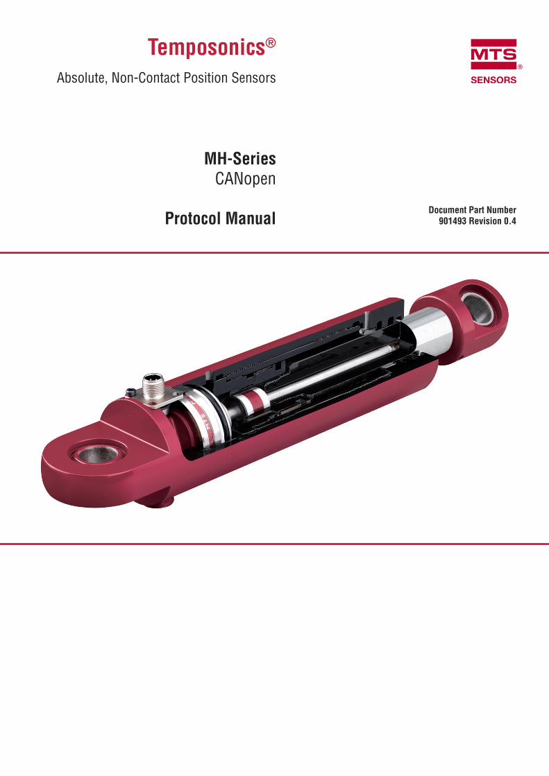
Temposonics®
Absolute, Non-Contact Position Sensors
MH-SeriesCANopen
Protocol Manual Document Part Number
901493 Revision 0.4

Temposonics® MHProtocol Manual CANopen
I 2 I
Rev. By Date Changes Areas Affected Comments
0.1 PL April 13th 2010 First released
0.2 PL February 11th 2011 Manufacturer Area deleted
0.3 PL March 18th 2011 Deleted PDO message format now only standard Formally 12 11.1.4
0.4 PL Jan 28th 2013 Object table overworked 10.3
1. History
Temposonics® MHProtocol Manual CANopen
I 3 I
2 Index of Contents
1 History 022 Index of Contents 033 List of Figures 044 List of Tables 045 Abbreviations 056 General functional 057 Network Management 06 7.1 Module Control Protocol 06 7.1.1 Start_Remot_Node indication (3),(6) 06 7.1.2 Enter_PRE-OPERATIONAL_STATE indication (4),(7) 07 7.1.3 Stop_Remote indication (5),(8) 07 7.1.4 Reset_Node indication (9),(10),(11) 08 7.1.5 Reset_Communication indication (12),(13),(14) 08 7.2 Network Initialisation 08 7.3 Network Pro-Operational State 09 7.4 Network Operational State 09 7.5 Network Stopped State 098 Emergency Object / Mal function 099 Error Control Service 1110 Configuration 12 10.1 LSS Protocol for CANopen 12 10.1.1 Node ID 13 10.1.2 Baud rate 13 10.1.3 Activate Bit timing parameter 14 10.1.4 Store Configuration Data 14 10.1.5 Inquiry and Identification services 14 10.2 SDO Services 15 10.2.1 SDO Download 15 10.2.2 SDO Upload 15 10.2.3 SDO Abort 15 10.3 Object dictionary 16 10.3.1 SDO Objects 1811 Process Data 24 11.1 Transmission the data 24 11.1.1 Synchronous mode 24 11.1.2 Polling with remote frames 24 11.1.3 Asynchronous mode 24 11.1.4 PDO message format 25 11.1.5 PDF error behaviour 2512 Literature 26

Temposonics® MHProtocol Manual CANopen
I 4 I
3 List of figures
Figure 1 MNT State machine 06Figure 2 Start Node message 06Figure 3 Enter Pre-Operational message 07Figure 4 Stop Node message 07Figure 5 Reset Node message 08Figure 6 Reset Communication message 08Figure 7 Boot-up protocol message 08Figure 8 Emergency Object message 09Figure 9 Heartbeat Protocol message 11Figure 10 LSS Switch Mode Selective sequence 12Figure 11 LSS Switch Mode Global 12Figure 12 Configure Node ID protocol 13 Figure 13 Configure Bit-timing parameters protocol 13Figure 14 Activate Bit timing protocol 14 Figure 15 Store LSS Configuration protocol 14Figure 16 SDO Download protocol 15Figure 17 SDO Upload protocol 15Figure 18 SDO Abort protocol 15Figure 19 Manufacturer Status Register definition 18Figure 20 Store all parameters command 19Figure 21 Restore default parameters command 20Figure 22 SYNC Object 24Figure 23 PDO Remote frame 24Figure 24 PDO format 25
4 List of tables
Table 1 Trigger for State Transition 06Table 2 Error Code 10Table 3 Error Register 10Table 4 Heartbeat Protocol Date 11Table 5 LSS Address 12Table 6 Baud Rate Indices 13Table 7 SDO Abort Codes 14Table 8 Description of PDO COB-ID entry 21Table 9 Transmission Type values 21Table 10 Event Timer 21

Temposonics® MHProtocol Manual CANopen
I 5 I
5 Abbreviations
Tx - MH CANopen sensor is the producer of the CAN data frameRx - MH CANopen sensor is the consumer of the CAN data frameSDO - Service Data ObjectPDO - Process Data ObjectSRDO - Safety Relevant Data ObjectCiA - CAN in Automation e.V.ro - read onlyrw - read/writewo - write only
6 Abbreviations
This document reflects the MTS Position Sensor protocol implementation of the standard CANopen protocol.The Sensor supports the CANopen Communication profile DS301 V4.02, the Encoder profile DS406 V3.2 and the LSS Services DS305 V2.1.1

Temposonics® MHProtocol Manual CANopen
I 6 I
7 Network Management
The MH CANopen sensor is used in a CANopen network with a slave functionality,So, normally a CANopen master has the control over the MH CANopen sensor in a CANopen network.
The following description is part of the CANopen communication profile DS301.
7.1 Module Control Protocol
The following messages are not confirmed by the MH CANopen sensor.
7.1.1 Start_Remote_Node indication (3),(6)
Through this service the NMT Master sets the state of the selected NMT slaves to OPERATIONAL.
PAR - 0 All devicesPAR - Node ID This device
Table 1 Trigger for State Transition
Figure 2 Start Node message
Power on or Hardware Reset
Figure 1 MNT State machine
(14) (2) (11)
(1)
(13)
(12) (8)
(6)
(4)
(3)
(5)
(7) (10)
(9)
Initialisation
Operational
Stopped
Pre-Operational
(1) At Power on the initialisation state is entered autonomously
(2) Initialisation finished - enter PRE-OPERATIONAL automatically
(3),(6) Start_Remote_Node indication
(4),(7) Enter_PRE-OPERATIONAL_STATE
(5),(8) Stop_Remote_Node indication
(9),(10),(11) Reset_Node indication
(12),(13),(14) Reset Communication indication
COB-ID Rx/Tx DLCData
D0 D1 D2 D3 D4 D5 D6 D7
0x000 Rx 2 0x01 PAR - - - - - -

Temposonics® MHProtocol Manual CANopen
I 7 I
7.1.2 Enter_PRE-OPERATIONAL_STATE indication (4),(7)
Through this service the NMT Master sets the state of the selected NMT slave(s) to „PREOPERATIONAL“.
7.1.3 Stop_Remote indication (5),(8)
Through this service the NMT Master sets the state of the selected NMT slaves to STOPPED.
PAR - 0 All devicesPAR - Node ID This device
PAR - 0 All devicesPAR - Node ID This device
Figure 3 Enter Pre-Operational message
Figure 4 Stop Node message
COB-ID Rx/Tx DLCData
D0 D1 D2 D3 D4 D5 D6 D7
0x000 Rx 2 0x80 PAR - - - - - -
COB-ID Rx/Tx DLCData
D0 D1 D2 D3 D4 D5 D6 D7
0x000 Rx 2 0x02 PAR - - - - - -

Temposonics® MHProtocol Manual CANopen
I 8 I
7.1.4 Reset_Node indication (9),(10),(11)
Through this service the NMT Master sets the state of the selected NMT Slave(s) from any state to the „reset application“ sub-state.
7.1.5 Reset_Communication indication (12),(13),(14)
Through this service the NMT Master sets the state of the selected NMT Slave(s) from any state to the „reset communication“ sub-state. After completi-on of the service, the state of the selected remote nodes will be RESET COMMUNICATION.
7.2 Network initialisation
When powering the sensor or after a NMT Reset command (7.1.4 and 7.1.5) or after an internal Reset the sensor enters automatically the NMT Initiali-sation state. In this state the MH CANopen sensor loads all parameter from the non-volatile memory into the RAM of the internal microcontroller. Also the microcontroller performs several test function and configuration tasks. In this state is no communication with the MH CANopen sensor possible. After finishing the NMT Initialisation state the MH CANopen sensor enters automatically the NMT Pre-Operational state. During that state transition the MH CANopen sensor sends automatically its Boot-up protocol message.
Note: The COB-ID of the Boot-up protocol is the same as for the heartbeat message. This COB-ID can be individually programmed with Index 100E. (see 10.2 ) So the COB-ID of the Boot-up message can be different.
PAR - 0 All devicesPAR - Node ID This device
PAR - 0 All devicesPAR - Node ID This device
Figure 5 Reset Node message
Figure 6 Reset Communication message
Figure 7 Boot-up protocol message
COB-ID Rx/Tx DLCData
D0 D1 D2 D3 D4 D5 D6 D7
0x000 Rx 2 0x81 PAR - - - - - -
COB-ID Rx/Tx DLCData
D0 D1 D2 D3 D4 D5 D6 D7
0x000 Rx 2 0x82 PAR - - - - - -
COB-ID Rx/Tx DLCData
D0 D1 D2 D3 D4 D5 D6 D7
0x700 +Node-ID Tx 2 0x00 - - - - - - -
Temposonics® MHProtocol Manual CANopen
I 9 I
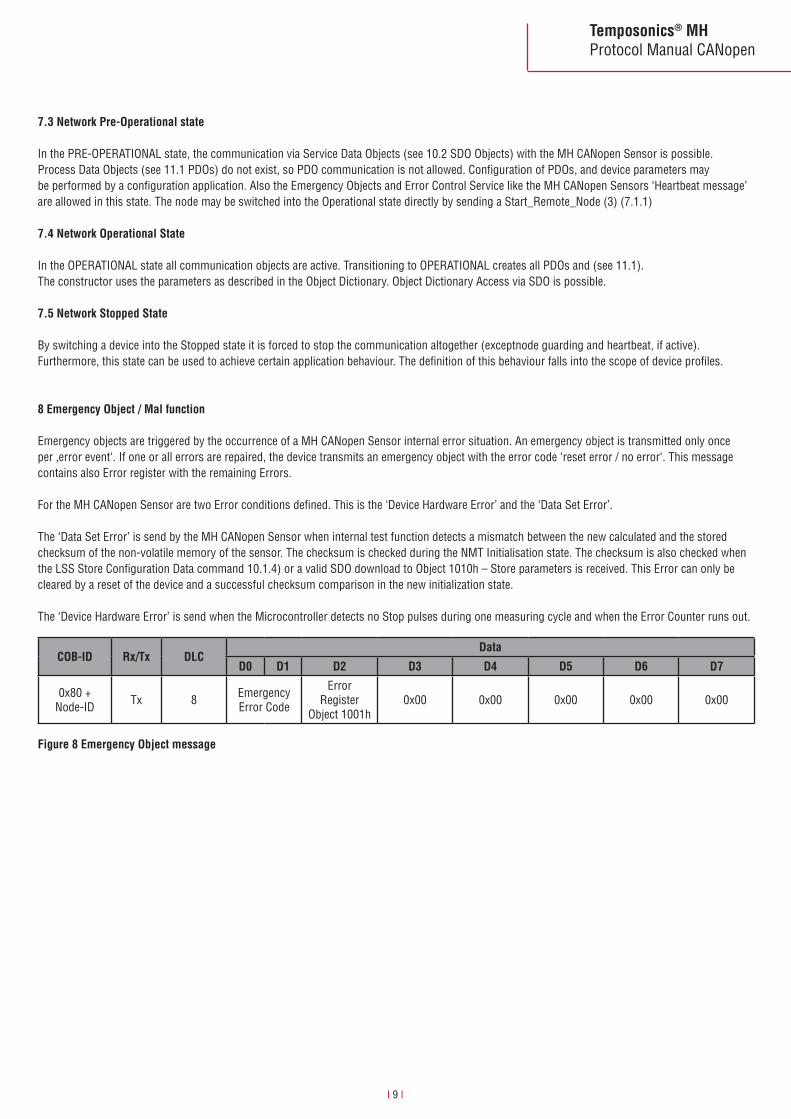
7.3 Network Pre-Operational state
In the PRE-OPERATIONAL state, the communication via Service Data Objects (see 10.2 SDO Objects) with the MH CANopen Sensor is possible. Process Data Objects (see 11.1 PDOs) do not exist, so PDO communication is not allowed. Configuration of PDOs, and device parameters may be performed by a configuration application. Also the Emergency Objects and Error Control Service like the MH CANopen Sensors ‘Heartbeat message’ are allowed in this state. The node may be switched into the Operational state directly by sending a Start_Remote_Node (3) (7.1.1)
7.4 Network Operational State
In the OPERATIONAL state all communication objects are active. Transitioning to OPERATIONAL creates all PDOs and (see 11.1). The constructor uses the parameters as described in the Object Dictionary. Object Dictionary Access via SDO is possible.
7.5 Network Stopped State
By switching a device into the Stopped state it is forced to stop the communication altogether (exceptnode guarding and heartbeat, if active). Furthermore, this state can be used to achieve certain application behaviour. The definition of this behaviour falls into the scope of device profiles.
8 Emergency Object / Mal function
Emergency objects are triggered by the occurrence of a MH CANopen Sensor internal error situation. An emergency object is transmitted only once per ‚error event‘. If one or all errors are repaired, the device transmits an emergency object with the error code ‘reset error / no error‘. This message contains also Error register with the remaining Errors.
For the MH CANopen Sensor are two Error conditions defined. This is the ‘Device Hardware Error’ and the ‘Data Set Error’.
The ‘Data Set Error’ is send by the MH CANopen Sensor when internal test function detects a mismatch between the new calculated and the stored checksum of the non-volatile memory of the sensor. The checksum is checked during the NMT Initialisation state. The checksum is also checked when the LSS Store Configuration Data command 10.1.4) or a valid SDO download to Object 1010h – Store parameters is received. This Error can only be cleared by a reset of the device and a successful checksum comparison in the new initialization state.
The ‘Device Hardware Error’ is send when the Microcontroller detects no Stop pulses during one measuring cycle and when the Error Counter runs out.
Figure 8 Emergency Object message
COB-ID Rx/Tx DLCData
D0 D1 D2 D3 D4 D5 D6 D7
0x80 +Node-ID Tx 8 Emergency
Error Code
ErrorRegister
Object 1001h0x00 0x00 0x00 0x00 0x00

Temposonics® MHProtocol Manual CANopen
I 10 I
Error Code (hex) Meaning
0x0000 Error Reset or No Error
0x5000 Device Hardware
0x6300 Data Set
Error Code (hex) Meaning
0x00 No Error
0x01 Data Set Error
0x81 Device Hardware Error orDevice Hardware Error and Data Set Error
The possible Error Codes are:
The Error Register can contain the following data:
Table 2 Error Code
Table 3 Error Register
Note: The COB-ID of the Emergency Object message can be individually programmed with Index 1014. (see 10.2 ) So the COB-ID of the Emergency message can be different.

Temposonics® MHProtocol Manual CANopen
I 11 I
STATE Meaning
0x00 Bootup
0x04 Stopped
0x05 Operational
0x7F Pre-Operational
Figure 9 Heartbeat Protocol message
Table 4 Heartbeat Protocol Data
Note: This COB-ID can be individually programmed with Index 100E. (see 10.2 ) So the COB-ID of the Heartbeat Protocol message can be different.
9 Error Control Service
Through Error control services the NMT detects failures in a CAN-based Network. When the Error Control service is enabled the MH CANopen Sensor transmits a Heartbeat message cyclically. One or more Heartbeat Consumer receives the indication. The relationship between producer and consumer is configurable via the object dictionary by SDO. By default the Heartbeat is disabled. The first byte of the Heartbeat message contains the actual Network Management State of the MH CANopen Sensor.
COB-ID Rx/Tx DLCData
D0 D1 D2 D3 D4 D5 D6 D7
0x700 + Node-ID Tx 1 STATE - - - - - - -

Temposonics® MHProtocol Manual CANopen
I 12 I
10 Configuration
The complete configuration of the MH CANopen Sensor is done through the CAN Bus interface.
10.1 LSS Protocol for CANopen
Every CANopen Device must have a unique Node-Identifier in the actual CANopen network. The Node Id and the Baud rate can be programmed by using the LSS Protocol DS305 published by the CiA. To program the Node ID and/or the Baud rate the MH CANopen Sensor has change to the LSS Configuration State. There are two ways to switch the MH CANopen Sensor to the LSS Configuration State.
• LSS Switch Mode Selective In this case only the addressed device is switched to the LSS Configuration State. The configuration tool uses the unique LSS Address. The MH CANopen LSS Address has the following structure:
With the following sequence you can switch the MH CANopen sensor to the LSS Configuration State
- Serial Number in this example: 0x09501234
• LSS Switch Mode Global In this case all CANopen devices supporting the LSS Service are switched to the LSS Configuration State.
LSS Address Meaning
Vendor-ID 0x40
Product Code 0x43787800
Revision Number 0x312E3031
Serial Number Actual MH CANopen Sensors Serial Number
Table 5 LSS Address
Figure 10 LSS Switch Mode Selective sequence
Figure 11 LSS Switch Mode Global
COB-ID Rx/Tx DLCData
D0 D1 D2 D3 D4 D5 D6 D7
0x7E5 Rx 8 0x40 0x40 0x00 0x00 0x00 0x00 0x00 0x00
0x7E5 Rx 8 0x41 0x00 0x78 0x78 0x43 0x00 0x00 0x00
0x7E5 Rx 8 0x42 0x31 0x30 0x2E 0x31 0x00 0x00 0x00
0x7E5 Rx 8 0x43 0x34 0x12 0x50 0x09 0x00 0x00 0x00
0x7E5 Tx 8 0x44 0x00 0x00 0x00 0x00 0x00 0x00 0x00
COB-ID Rx/Tx DLCData
D0 D1 D2 D3 D4 D5 D6 D7
0x7E5 Rx 8 0x04 0x01 0x00 0x00 0x00 0x00 - -
When the CANopen devices are in Configuration State the Node ID and/or the Baud rate can be changed.

Temposonics® MHProtocol Manual CANopen
I 13 I
Figure 12 Configure Node ID protocol
Note: The new Node ID gets immediately active after a successful Response message of the MH CANopen sensor. The following COB-IDs are automatically updated according to the Pre-defined Connection Set of the #2 DS301.SDO(Tx); SDO(Rx); Emergency; Error control; PDO1(Tx)
Note: The Baud rate gets active after receiving the ‘Activate Bit timing parameters‘ command or after the ‘Store Configuration Data‘ command with the next Power on Reset.
10.1.1 Node ID
With the following command the Node ID can be programmed.
10.1.2 Baud rate
With the following command the Baud rate can be programmed.
COB-ID Rx/Tx DLCData
D0 D1 D2 D3 D4 D5 D6 D7
0x7E5 Rx 8 0x11 N ID 0x00 0x00 0x00 0x00 0x00 0x00
0x7E4 Tx 8 0x11 Err Code 0x00 0x00 0x00 0x00 0x00 0x00
COB-ID Rx/Tx DLCData
D0 D1 D2 D3 D4 D5 D6 D7
0x7E5 Rx 8 0x13 0x00 Table Index 0x00 0x00 0x00 0x00 0x00
0x7E4 Tx 8 0x13 Err Code 0x00 0x00 0x00 0x00 0x00 0x00
N ID The new Node ID in the range of 1 to 127Err Code 0 - protocol successfully completed 1 - Node ID out of range
Figure 13 Configure Bit-timing parameters protocol
Table 6 Baud rate indices
Table index Bit rate
0 1000 kbit/s
1 800 kbits
2 500 kbit/s
3 250 kbit/s
4 125 kbit/s
5 Reserved
6 50 kbit/s
7 20 kbit/s
8 10 kbit/s
Err Code: 0 - protocol successfully completed 1 - Bit timing not supported

Temposonics® MHProtocol Manual CANopen
I 14 I
10.1.3 Activate Bit timing parameter
With the following command the LSS master shall activate the bit timing defined by the configure bit timing parameters service.
10.1.4 Store Configuration Data
With the following command the LSS Configuration Data (Node ID and Baud rate) is stored to the nonvolatile memory of the MH CANopen sensor.
10.1.5 Inquiry and identification services
The MH CANopen sensor supports also the inquiry and identification services described in the LSS protocol. (See #1 DS 305 for details).
Figure 14 Activate Bit timing protocol
Figure 15 Store LSS Configuration protocol
COB-ID Rx/Tx DLCData
D0 D1 D2 D3 D4 D5 D6 D7
0x7E5 Rx 8 0x15 Switch delay 0x00 0x00 0x00 0x00 0x00
COB-ID Rx/Tx DLCData
D0 D1 D2 D3 D4 D5 D6 D7
0x7E5 Rx 8 0x17 0x00 0x00 0x00 0x00 0x00 0x00 0x00
0x7E4 Tx 8 0x17 Err Code 0x00 0x00 0x00 0x00 0x00 0x00
Switch delay: Time in ms internal multiplied by 2 when the new Bit timing parameters become active.
Err Code: 0 - Protocol successfully completed 2 - Storage media access error
Note: No communication should be performed until the (2*Switch delay) time runs out.
Temposonics® MHProtocol Manual CANopen
I 15 I
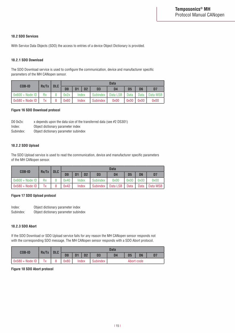
10.2.1 SDO Download
The SDO Download service is used to configure the communication, device and manufacturer specific parameters of the MH CANopen sensor.
10.2.2 SDO Upload
The SDO Upload service is used to read the communication, device and manufacturer specific parameters of the MH CANopen sensor.
10.2.3 SDO Abort
If the SDO Download or SDO Upload service fails for any reason the MH CANopen sensor responds not with the corresponding SDO message. The MH CANopen sensor responds with a SDO Abort protocol.
10.2 SDO Services
With Service Data Objects (SDO) the access to entries of a device Object Dictionary is provided.
COB-ID Rx/Tx DLCData
D0 D1 D2 D3 D4 D5 D6 D7
0x600 + Node ID Rx 8 0x2x Index Subindex Data LSB Data Data Data MSB
0x580 + Node ID Tx 8 0x60 Index Subindex 0x00 0x00 0x00 0x00
COB-ID Rx/Tx DLCData
D0 D1 D2 D3 D4 D5 D6 D7
0x600 + Node ID Rx 8 0x40 Index Subindex 0x00 0x00 0x00 0x00
0x580 + Node ID Tx 8 0x42 Index Subindex Data LSB Data Data Data MSB
COB-ID Rx/Tx DLCData
D0 D1 D2 D3 D4 D5 D6 D7
0x580 + Node ID Tx 8 0x80 Index Subindex Abort code
D0 0x2x: x depends upon the data size of the transferred data (see #2 DS301)Index: Object dictionary parameter indexSubindex: Object dictionary parameter subindex
Index: Object dictionary parameter indexSubindex: Object dictionary parameter subindex
Figure 16 SDO Download protocol
Figure 17 SDO Upload protocol
Figure 18 SDO Abort protocol

Temposonics® MHProtocol Manual CANopen
I 16 I
Abort Code Meaning
0x06090011 Subindex does not exist
0x06090030 Value exceeded
0x06020000 Object does not exist
0x06010001 Object is write only
0x06010002 Object is read only
0x08000020 Data transport error
0x08000000 General error
0x08000022 Wrong state
Table 7 SDO abort codes
10.3 Object dictionary
The following table shows all parameters implemented in the MH CANopen sensor.
Communication Profile Area
Index Subindex Name Typ Attribute Default value Comment
1000 0 device type unsigned32 ro x196x0A
device profile 406multi-sensor encoder interface
1001 0 error register unsigned8 ro 0 0x00: No error0x81: transducer error
1002 0 manufacturer status register unsigned8 ro 1 Additional status register
1005 0 COB-ID SYNC-message unsigned32 rw 80h COB-ID SYNC-message
1008 0 manufacturer device name
visible string const C01 device name
1009 0 manufacturer hardware version visible string const 1.00 hardware version release
100A 0 manufacturer software version visible string const 1.00 software version release
100B 0 Node-ID unsigned32 ro 127 Node-ID can be changed via LSS protocol
100E 0 COB-ID Error Control unsigned32 rw 700h + Node ID error control identifier (should not be changed)
1010 0 1
store parameters unsigned8unsigned32
rorw
11
number of largest sub-index writing the signature ‘save‘ will store all parameters into EEPROM (73, 61, 76, 65)
1011 0 1
restore default parameters unsigned8 unsigned32
rorw
11
number of largest sub-index writing the signature ‘load’ will load all parameters with default values (6C, 6F, 61, 64)
1014 0 COB-ID emergency unsigned32 rw 80h + Node ID COB-ID emergency message
1017 0 producer heartbeat time unsigned16 rw 0 time period in ms
1018 0 1 2 3 4
identity object unsigned8unsigned32unsigned32unsigned32 unsigned32
rororororo
40x400x43787800xxxxxxxx
number of entriesVendor-IDproduct code (ASCII C01)revision numberserial number
1200 0 1 2
1st server SDO parameter unsigned8unsigned32unsigned32
rororo
2600h + Node ID580h + Node ID
number of largest sub-indexCOB-ID client > server (Rx)COB-ID server > client (Tx)

Temposonics® MHProtocol Manual CANopen
I 17 I
Device Profile Area - DS406
Index Subindex Name Typ Attribute Default value Comment
6000 0 operating parameter unsigned16 rw 0 operating parameters
6005 012
linear encodermeasuring stepsettings
unsigned8unsigned32unsigned32
rororo
2100000100
number of objectsposition measuring step in 0.001 µmspeed measuring step in 0.01 µm
6010 01
present value unsigned8integer32
rwrw
1xxxx
number of available channelspresent value channel 1
6020 01
position value unsigned8integer16
roro
1no
number of available channelsposition value channel 1
6030 01
speed value unsigned8integer16
roro
1no
number of available channelsspeed value channel 1
6200 0 cyclic timer unsigned16 rw 1 cyclic timer value in ms if value > 0
6500 0 operating status unsigned16 ro no operating status
6501 0 measuring step unsigned32 ro 100000 position measuring step in 0.001 µm
Index Subindex Name Typ Attribute Default value Comment
1800 01
2
5
1st transmit PDOparameter
unsigned8unsigned32
unsigned8
unsigned16
rorw
rw
rw
5180h + Node ID
254
1
number of largest sub-indexCOB-ID used by PDO1transmission type of PDO1 0–240 : transmission on SYNC message 254: transmission runs asynchronousevent timer
1A00 012
1st trasmit PDOmapping
unsigned32unsigned32unsigned32
constconstconst
26020012060300110
number of largest sub-index 1st mapping parameter2nd mapping parameter

Temposonics® MHProtocol Manual CANopen
I 18 I
10.3.1 SDO Objects
Object 1000h - Device Type
Index Sub Name Data type Access Range/Value Default
1000h 0 Device type unsigned32 ro 0x000A0196 0x000A0196
Object 1000h - Error Type
Index Sub Name Data type Access Range/Value Default
1001h 0 Error register unsigned8 ro 0x000A0196 0x000A0196
Object 1002h - Manufacture Status Register
Index Sub Name Data type Access Range/Value Default
1002h 0 Manufacture Status Register unsigned8 ro 1
Object 1005h - COB-ID Sync
Index Sub Name Data type Access Range/Value Default
1005h 0 COB-ID Sync unsigned32 rw 0…0x7FF 0x80
D7 D6 D5 D4 D3 D2 D1 D0
0 T E3 E2 E1 E0 S N
For details see 8 emergency object / mal function
Different to the #2 DS301 the data type of the MH CANopen sensor is unsigned8 instead of unsigned32. The definition of the manufacture status register is as follows:
This Object defines the COB-ID of the Sync Message used in the NMT Operational state for PDO in Synchronous mode. The MH CANopen Sensor expects the Sync message with this defined COB-ID. The Sync is described in 11.1.1 Synchronous Mode.
Figure 19 Manufacturer status register definition
N: Status 0 = sensor in error state 1 = normal running state valid position and velocity data transmittedS: Start up 0 = normal running state 1 = start up or internal test modeE0: Magnet Error 0 = one magnet detected 1 = no or more than one magnet detectedE1: Range Error 0 = no error 1 = the calculated position is out of range when also the position and velocity value is set to zero 1 = the velocity value maybe not correctE2: Data flash error 0 = no error 1 = the CRC check of data flash parameter memory failedE3: Controller error 0 = no error 1 = the internal test routines detects an errorT: Temperature µC 0 = T < Max temperature 1 = T > Max temperature

Temposonics® MHProtocol Manual CANopen
I 19 I
Object 1008h - Manufacturer Device Name
Index Sub Name Data type Access Range/Value Default
1008h 0 Manufacturer device name visible string const C01
Object 1009h - Manufacturer Hardware Version
Index Sub Name Data type Access Range/Value Default
1009h 0 Manufacturer Hardware Version visible string const 1.00
Object 100Ah - Manufacturer Software Version
Index Sub Name Data type Access Range/Value Default
100Ah 0 Manufacturer Software Version visible string const 1.00
Object 100Bh - Node ID
Index Sub Name Data type Access Range/Value Default
100Bh 0 Node ID unsigned32 rw 1…127 127
Object 100Eh - COB-ID Error Control
Index Sub Name Data type Access Range/Value Default
100Eh 0 COB-ID error control unsigned32 rw 0…0x7FF 0x700 + Node ID
Object 1010h - Store parameters
Index Sub Name Data type Access Range/Value Default
1010h 0 Store parameters unsigned8 ro 1 1
1 All parameters unsigned32 rw 0x73617665 0x73617665
This object defines the COB-ID of the heartbeat and boot-up message (see 9 error control service).
A valid SDO download to this objects stores all changeable parameters of the communication and device profile to the non-volatile memory of the MH CANopen sensor.
COB-ID Rx/Tx DLCData
D0 D1 D2 D3 D4 D5 D6 D7
0x600 + Node ID Rx 8 0x23 0x10 0x10 0x01 0x73 0x61 0x76 0x65
0x580 + Node ID Tx 8 0x60 0x10 0x10 0x01 0x00 0x00 0x00 0x00
Figure 20 Store all parameters command

Temposonics® MHProtocol Manual CANopen
I 20 I
Object 1011h - Restore default parameters
Index Sub Name Data type Access Range/Value Default
1011h 0 Restore default parameters unsigned8 ro 1 1
1 All parameters unsigned32 rw 0x6C6F6164 0x6C6F6164
Object 1014h - COB-ID emergency
Index Sub Name Data type Access Range/Value Default
1014h 0 COB-ID emergency unsigned32 rw 0…0x7FF 0x80 + Node ID
Object 1017h - Producer heartbeat time
Index Sub Name Data type Access Range/Value Default
1017h 0 Producer heartbeat time unsigned16 rw 0…65535 0
COB-ID Rx/Tx DLCData
D0 D1 D2 D3 D4 D5 D6 D7
0x600 + Node ID Rx 8 0x23 0x11 0x10 0x01 0x6C 0x6F 0x61 0x64
0x580 + Node ID Tx 8 0x60 0x11 0x10 0x01 0x00 0x00 0x00 0x00
Figure 21 Restore default parameters command
A valid SDO Download to this object restores all changeable parameters of the communication and device profile in the non-volatile memory of the MH CANopen sensor. The new restored values become active after any reset of the MH CANopen Sensor. The restore values are defined in the # 2 DS301 and # 3 DS406.
With this object you can set the producer heartbeat time of the error control function of the MH CANopen sensor. The value is given in ms. Value 0 disables the heartbeat function. (see 9 Error Control Service)
This object defines the COB-ID of the emergency message (see 8 emergency object / mal function).

Temposonics® MHProtocol Manual CANopen
I 21 I
Object 1018h - Identity object
Index Sub Name Data type Access Range/Value Default
1018h 0 Number of entires unsigned8 ro 4 4
1 Vendor-ID unsigned32 rw 0x40 0x40
2 Product code unsigned32 rw 0x43787800 0x43787800
3 Revision number unsigned32 rw 0x312E3031 0x312E3031
4 Serial number unsigned32 rw
Object 1200h - 1st Server SDO parameter
Index Sub Name Data type Access Range/Value Default
1200h 0 Number of entires unsigned8 ro 2 2
1 COB-ID client -> server (Rx) unsigned32 ro 0x600 + Node ID
2 COB-ID server -> client (Tx) unsigned32 ro 0x580 + Node ID
Object 1800h - 1st PDO parameter
Index Sub Name Data type Access Range/Value Default
1800h 0 Largest subindex unsigned8 ro 5 5
1 COB-ID PDO unsigned32 rw 0x180 + Node ID
2 Transmission type unsigned8 rw 0…255 254
5 Event timer unsigned16 rw 0…65535 1
Table 8 Description of PDO COB-ID entry
Table 9 Transmission type values
Table 10 Event timer
The identity object contains general information about the MH CANopen sensor.This information are also used as the LSS address when using the ‘Switch mode selective’ command.
Subindex 1 contains the COB-ID of the PDO. The PDO can also be disable with this parameter.
The transmission type (sub-index 2) defines the transmission character of the PDO.
For details about the PDO transmission mode see 11.1If the transmission type is set to 254 or 255 the PDO transmission is asynchronous from the sync object. The PDO transmission rate is defined by the event timer or cyclic timer (Index 6200; 2).
Bit number Value Meaning
31 (MSB) 0 PDO exists/valid
1 PDO does not exist / is not valid
10-0 (LSB) X Bits of PDO COB-ID
Event timer Meaning
0 PDO transmission disabled
1 - 65535 PDO transmission in [ms]
Transmission type PDO Transmission synchronous
PDO Transmission asynchronous
RTR only
0 - 240 X
254; 255 X
252; 253 X X
241 - 251 not valid reserved
Temposonics® MHProtocol Manual CANopen
I 22 I
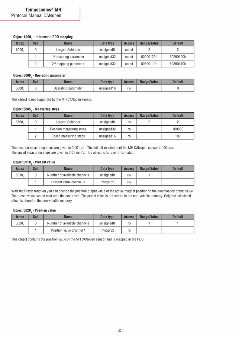
Object 1A00h - 1st transmit PDO mapping
Index Sub Name Data type Access Range/Value Default
1A00h 0 Largest Subindex unsigned8 const 2 2
1 1st mapping parameter unsigned32 const 60200120h 60200120h
2 2nd mapping parameter unsigned32 const 60300110h 60300110h
Object 6005h - Measuring steps
Index Sub Name Data type Access Range/Value Default
6500h 0 Largest Subindex unsigned8 ro 2 2
1 Position measuring steps unsigned32 ro 100000
2 Speed measuring steps unsigned16 ro 100
Object 6010h - Present value
Index Sub Name Data type Access Range/Value Default
6010h 0 Number of available channels unsigned8 rw 1 1
1 Present value channel 1 integer32 rw
Object 6020h - Position value
Index Sub Name Data type Access Range/Value Default
6020h 0 Number of available channels unsigned8 ro 1 1
1 Position value channel 1 integer32 ro
Object 6000h - Operating parameter
Index Sub Name Data type Access Range/Value Default
6000h 0 Operating parameter unsigned16 rw 0
This object is not supported by the MH CANopen sensor.
The position measuring steps are given in 0.001 µm. The default resolution of the MH CANopen sensor is 100 µm. The speed measuring steps are given in 0.01 mm/s. This object is for user information.
With the Preset function you can change the position output value of the actual magnet position to the downloaded preset value. The preset value can be read until the next reset. The preset value is not stored in the non-volatile memory. Only the calculated offset is stored in the non-volatile memory.
This object contains the position value of the MH CANopen sensor and is mapped in the PDO.

Temposonics® MHProtocol Manual CANopen
I 23 I
Object 6030h - Speed value
Index Sub Name Data type Access Range/Value Default
6030h 0 Number of available channels unsigned8 ro 1 1
1 Speed value channel 1 integer16 ro
Object 6200h - Cyclic timer
Index Sub Name Data type Access Range/Value Default
6200h 0 Cyclic timer unsigned16 rw 1
Object 6500h - Operating status
Index Sub Name Data type Access Range/Value Default
6500h 0 Operating status unsigned16 ro 0
Object 6501h - Measuring step
Index Sub Name Data type Access Range/Value Default
6501h 0 Measuring step unsigned32 ro 100000
This object contains the speed value of the MH CANopen sensor and is mapped in the PDO.
This object is not supported by the MH CANopen sensor.
This object has the same functionality as object 6005h subindex 1.The measuring step is given in 0.001 µm. The default resolution of the MH CANopen sensor is 100 µm.
If the transmission type is set to 254 or 255 the PDO transmission is asynchronous from the sync object. The PDO transmis-sion rate is defined by the cyclic timer or event timer (Index1800;5).
Cyclic Timer Meaning
0 PDO transmission disabled
1 - 65535 PDO transmission in [ms]
Temposonics® MHProtocol Manual CANopen
I 24 I
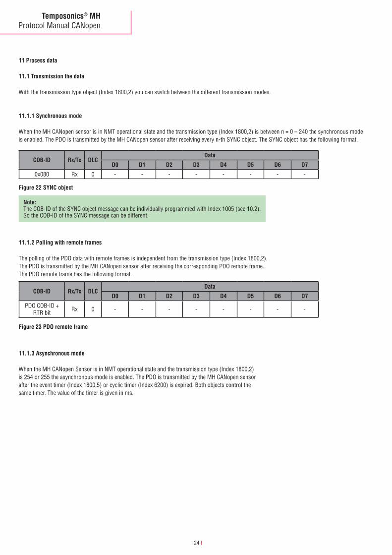
11 Process data
11.1 Transmission the data
With the transmission type object (Index 1800,2) you can switch between the different transmission modes.
11.1.1 Synchronous mode
When the MH CANopen sensor is in NMT operational state and the transmission type (Index 1800,2) is between n = 0 – 240 the synchronous mode is enabled. The PDO is transmitted by the MH CANopen sensor after receiving every n-th SYNC object. The SYNC object has the following format.
11.1.2 Polling with remote frames
The polling of the PDO data with remote frames is independent from the transmission type (Index 1800,2). The PDO is transmitted by the MH CANopen sensor after receiving the corresponding PDO remote frame. The PDO remote frame has the following format.
COB-ID Rx/Tx DLCData
D0 D1 D2 D3 D4 D5 D6 D7
0x080 Rx 0 - - - - - - - -
COB-ID Rx/Tx DLCData
D0 D1 D2 D3 D4 D5 D6 D7
PDO COB-ID + RTR bit Rx 0 - - - - - - - -
Figure 22 SYNC object
Figure 23 PDO remote frame
Note: The COB-ID of the SYNC object message can be individually programmed with Index 1005 (see 10.2). So the COB-ID of the SYNC message can be different.
11.1.3 Asynchronous mode
When the MH CANopen Sensor is in NMT operational state and the transmission type (Index 1800,2) is 254 or 255 the asynchronous mode is enabled. The PDO is transmitted by the MH CANopen sensor after the event timer (Index 1800,5) or cyclic timer (Index 6200) is expired. Both objects control the same timer. The value of the timer is given in ms.

Temposonics® MHProtocol Manual CANopen
I 25 I
11.1.4 PDO message format
This is the format of the MH CANopen sensor PDO message.The PDO message mapping can be seen at Index 1A00.
11.1.5 PDO error behaviour
The errors that can be detected by the MH CANopen sensor are defined in the object manufacture status register (Index 1002,0).
For the PDO message the actual measuring steps for the position (Pos) and speed values an be read with object linear encoder measuring step settings (Index 6005).
COB-ID Rx/Tx DLCData
D0 D1 D2 D3 D4 D5 D6 D7
0x180 + Node ID Tx 6 Pos LSB Pos Pos Pos
MSBSpeed LSB
Speed MSB - -
Figure 24 PDO format
Note: The COB-ID of the PDO message can be individually programmed with Index 1800, 1 (see 10.2).So the COB-ID of the PDO message can be different.
D7 D6 D5 D4 D3 D2 D1 D0
0 T E3 E2 E1 E0 S N
N: Status 0 = Sensor in error state Any error except temperature µC 1 = Normal running state Valid position and velocity data transmittedS: Start up 0 = Normal running state 1 = Start up or internal test mode No PDO communication possibleE0: Magnet Error 0 = One magnet detected Valid position and velocity data transmitted 1 = no magnet detected Position and velocity data set to zero 1 = No or more than one magnet detected Valid position and velocity data of the first magnet transmittedE1: Range Error 0 = No error 1 = The calculated position is out of range Position and velocity value is set to zero 1 = Position buffer has not 100 consecutively valid position values Valid position data transmitted Velocity data maybe not correctE2: Data flash error 0 = No error 1 = The CRC check of data flash parameter memory failed Position and velocity data set to zeroE3: Controller error 0 = No error 1 = the internal test routines detects an error Position and velocity data set to zeroT: Temperature µC 0 = T < Max temperature 1 = T > Max temperature Position and velocity data transmitted

Temposonics® MHProtocol Manual CANopen
I 26 I
12 Literature
# 1 CiA DS305 CANopen Layer Setting Service (LSS) V2.1.1 # 2 CiA DS301 CANopen Application Layer and Communication Profile V4.02 # 3 CiA DS406 CANopen Device profile for encoders V3.1

MTS Sensor TechnologieGmbH & Co. KGAuf dem Schüffel 958513 Lüdenscheid, GermanyTel. + 49-23 51-95 87 0Fax + 49-23 51-5 64 91E-Mail: [email protected]
MTS Systems CorporationSensors Division3001 Sheldon DriveCary, N.C. 27513, USATel. + 1-919-677-0100Fax + 1-919-677-0200E-Mail: [email protected]
MTS Sensors Technology Corp.737 Aihara-cho, Machida-shi, JapanTel. + 81-42-775-3838Fax + 81-42-775-5516E-Mail: [email protected]
Document Part Number: 901493 Revision 0.4 (EN) 02/2013MTS and Temposonics® are registered trademarks of MTS Systems Corporation. All other trademarks are
the property of their respective owners. Printed in Germany. Copyright © 2013 MTS Sensor Technologie GmbH & Co. KG. Alterations reserved. All rights reserved in all
media. No license of any intellectual property rights is granted. The information is subject to change without notice and replaces all data sheets previously supplied. The availability of components on the market is sub-ject to considerable fluctuation and to accelerated technical progress. Therefore we reserve the right to alter
certain components of our products depending on their availability. In the event that product approbations or other circumstances related to your application do not allow a change in components, a continuous supply
with unaltered components must be agreed by specific contract.