tempus cbc 20 connector system - home | itt cannon
TRANSCRIPT

Tempus CBC 20 Connector System

ITT Industries, Cannon ...providing a comprehensive offering of connectivity solutions.In addition to our comprehensive offering of connector products, we provide a complete line of electroniccomponents and solutions.
Metal or poly dome switch arrays
Modular assembly options include: ESD shielding, keypads, EL backlighting, rigid or flexible circuits
Complete design, engineering and test capabilities
Low, mid and high volume production capabilities
Rubber and In Mold Decoration (IMD) products
Wide range of cosmetic options
Integration of decorated and metalized plastic keytops
Multiple PILL and contact options
Precision molded polymeric solutions
From multi-function grips to sophisticated control systems, hall effect products and front panel assemblies
Electronics and software engineering development
Worldwide design and manufacturing
High-mix production capabilities
Global sourcing and supply chain management
SIM, full card, media and memory card configurations
Performance metal plating and inlays
Pick-and-place and IP65 compatible
“Spoon” shaped landing or friction contacts enhance interconnect performance and minimize damage fromdebris, mis-inserts and vandalism.
Top/side actuated tacts
Low profile SMT
Navigation/scrolling switches
Long life key switches
Toggle, rocker, pushbutton, DIP,slide, snap, switchlock, rotary, thumbwheel

Dimensions are shown mm (inch)Dimensions subject to change
www.ittcannon.com1
Tempus CBC 20
• 4 and 5 row high density connections with 2 mm x 2 mm circuit grid
• Push-fit peg at receptacles andrightangle males eliminate heat-staking and problems associated with this process
• Customized monoblock styles can be produced in economically valid quantities
• Solder and press-fit terminations are available
• Sequential mating provides live insertion capability
density connectors already on the mar-ket at present but none have beendesigned with such a system approachin mind and therefore the ability toexpand as required by technology.
TEMPUS CBC 20 contacts are laid outin four and more rows on a 2 mm pitchrather than three rows on a 0.1 inchpitch. This gives the designer the facilli-ty of 240 I/O lines in the same area pre-viously occupied by a 96 way DIN41612 style connector. Using TEMPUSas opposed to DIN 41612 connectors456 and more rather than 192 signalpositions may be obtained on a doubleeuroboard, over twice as many I/Olines, giving the ability to address largebus widths.
Introduction
Benefits
• Designed to conform with International specifications IEC 61076-4-104, IEE P896 Futurebus+, IEC 917 metric modular order
• End-to-End stackable with noloss of positions
• High performance contacts, high Hertz stress
• High temperature materials, notaffected by solder processes
• Modular design for signal andpower connectors
• Bellcore / CSA / UL approved
• Produced under ISO 9001 Quality Management System
With the growth of system circuit sizecombined with the requirement tomanipulate larger amounts of data atgreater speeds, bus systems and theirinterconnect components are beingpushed to their limits by the latestmicroprocessors. The restrictionsimposed by using the DIN 41612 con-nector and existing bus architecture arenow becoming evident. The electronicsindustry also accepts the requirementsto obey metric dimensional practices forfuture generations of components andequipment.
Cannon have responded to meet theserequirements - the result is TEMPUSCBC 20, a two part modular plug andreceptacle connector system. TEMPUSCBC 20 is suitable for a variety ofequipment ranging from laptops tomainframes, custom miniature packag-ing to telecom systems. There are high
Contents
The Industry Standard 2General Data 3Electrical Data 4 Mechanical Data 5System Overview 6Female Signal Modules, Solder 7 Female Signal Modules, Pressfit 9Female Power Modules, Solder 11Female Power Modules, Pressfit 13Male Signal Modules Solder 15Male Signal Modules, Wide Wall Pressfit 19Male Power Modules, Wide Wall Solder / Pressfit 23Male Right-Angle Signal Modules, Wide Wall 26Female Signal Modules, Pressfit 28Female Signal Modules, Pressfit/Solder 30Male Signal Modules, Solder 32Male Signal Modules, Pressfit 37Male Power Modules, Pressfit/Solder 46Male Right-Angle Signal Module 49Male Right-Angle Power Module 51Male Right-Angle Power/Signal Combined 53Female Straight Power Module 55Shrouds 57Hybrid Modules 59Guide Pin / Socket 60Cable Connectors, 4 Row 62Coding System 64Custom Monoblocks 66Typical Futurebus+ 67Standard Monoblocks 68Design Notes 71
Application ToolOverview 75Backplane Assembly 76Press Blocks, Support Blocks 78Right Angle Connectors 79Pushfit Press-in Tool 80Shroud Assembly 81Backplane Repair 82Cable Connector Assembly 83Product Safety Information 84
2 mm Interconnect

Dimensions are shown mm (inch)Dimensions subject to change
www.ittcannon.com2
Tempus CBC 20
• pressfit contacts with pushfit pegs for fast application in mass production
High Performance Contacts• High hertz stress design for high
reliability
• low insertion force (approximately half of DIN 41612 per signal contact)
• high cycle rate at low cost, 1000 cycles minimum as standard
Polarisaton• polarised by design
Coding• coding with no loss of contact
positions
Total System Capability
• signal
• power
• high power
• coaxial
• guiding pins
• guiding with early ground
• cable
• shrouds
• right angle males
• coding
• fibre optics
• backplane extension
• shielding
Live Insertion Capability• signal and power pins are available
in various lengths and positions within the connector modules
Power Handling• power modules available for 3 and
40 Amps, suitable for backplane internal power planes or bus-bar power levels
True Modular System• the ability to mix signal and power
with no loss of signal position with the easy addition of coax, fibre optics and other features
• flexible mix of technology and features allows freedom in design
Monoblock Capability• to complement the modular system
signals, power and other features are available within a single block for ease of application and a lowering of cost in volume applications
• unique modular mould tools allow custom connectors at attractive prices
Low Cost Application• pushfit pegs on plug-in board
mounted modules as an alternative to the standardised heat stake. Simple and fast application with “flatrock“ type tooling
• full application tool support for smallto large volumes and connector repair
Choice of Application andTermination• solder and pressfit termination on
backplane and circuit board mounted connectors
• high temperature materials allow use within surface mount assembly environments
• designed to conform with connector specifications IEC61076-4-104, EIAis64 and CECC draft 75101-810.
• designed to conform with the system build specifications of IEC917, IEEE1301 and IEEE1301.1
• selected as the interconnection system for Futurebus+, general computer, input/output and telecom profiles and Scalabe Coherent Interface
• qualified within major computer, telecom and backplane manufacturers throughout America, Europe, Japan and the Pacific rim
• standardisation guarantees multi-sourcing and compatibility with third party equipment
2mm Pitch• the optimum connector pitch with
reference to price and performance, greater contact density with no largeincrease in board and assembly costs
High I/O• provides over twice the signal pin
availability of DIN41612 on a doubleeurocard
• on a double eurocard: TEMPUS can provide 456 contacts (4 row) or 570 contacts (5 row), for reference DIN41612 provides 192 contacts
Optimum Performance• 45° legform for mechanical stability
and shortest stub length and highestsignal speed
• high I/O allows practical inclusion of ground return patterns for optimal signal integrity
• for high speed, 640 Mbits/s, signal rise times typically ten times faster than VMEbus with low crosstalk
2 mm Interconnect
Industry Standard

Dimensions are shown mm (inch)Dimensions subject to change
www.ittcannon.com3
Tempus CBC 20
Full test reports are available uponrequest. The following lists the IECspecification requirements.
Test Data Overview
Contact Arrangement
Insulator Material
Flammability Rating
Contact Materials and Plating
Plating Options
Contact Area
Termination Finish
Number of Contacts
24 signal
48 signal
96 signal
192 signal
30 signal
60 signal
120 signal
240 signal
8 power
10 power
Refer to relevant connector design notes, all arrangements are standardised inaccordance with IEC, EIA and IEEE specifications.
High Temperature Thermoplastic LCP (liquid crystal polymer) or PPS
UL 94V-0
CuSn6 (phosphor bronze) on female solder and press-fit
CuSn (phosphor bronze) on male press-fit / solder
Brass on male solder
Palladium Nickel plus Gold over Nickel base
Tin lead solder
Layouts Module Length
4 x 6 12,00 (.470)
4 x 12 24,00 (.940)
4 x 24 48,00 (1.890)
4 x 48 96,00 (3.780)5 x 6 12,00 (.470)
5 x 12 24,00 (.940)
5 x 24 48,00 (1.890)
5 x 48 96,00 (3.780)
4 x 2 12,00 (.470)5 x 2 12,00 (.470)
5,00 (.197) Power 6,50 (.256)
5,75 (.226) 7,25 (.285)
6,50 (.256) 8,00 (.315)
7,25 (.285)
8,00 (.315)
Standard Module Arrangement and Size
2,00 x 2,00 (.079 x .079)Contact Pitch
TEMPUS is a reverse system with the male pin contacts mounted on the backplane and the female socket contacts mounted on the daughtercard.
General Data
2 mm Interconnect
Standard Contact Mating Lengthmm(inches)
Signal

Dimensions are shown mm (inch)Dimensions subject to change
www.ittcannon.com4
Tempus CBC 20
500 V dc > 5000 MΩ
1000 V ac
Frequency 1MHz, 1ns risentime, mated connectors
< 2pF< 3pF
1 ns risetime, 50 Ω reference impedance
< 35 nH
500 ps risetime, 50 Ω reference impedance
< 225 ps
< 40 ps
1 ns risetime, 50Ω reference impedance, 2:1
grounded pattern
< 5%
1,50 A / 25°C, 1,00 A / 70°C
4,00 A / 25°C, 3,00 A / 70°C
< 25 mΩ< 35 mΩ< 40 mΩ< 50 mΩ< 50 mΩ
< 10 mΩ
Signal Contacts
Power Contacts
Contact Resistance
Signal
Row A
Row B
Row C
Row D
Row E
Power
all rows
Insulation Resistance
Test Voltage
Voltage Proof
(IEC 512-2 test 40 method A)
Capacitance
Between lines
Between one line all other surrounded
Inductance
Between adjacent Lines
Propagation Delay
Propagation Delay
Skew Row-to-Row
Cross Talk
Signal
Near End Cross talk
Current rating (ambient temperature)
Electrical Data
2 mm Interconnect
Dimensions are shown mm (inch)Dimensions subject to change
www.ittcannon.com5
Tempus CBC 20
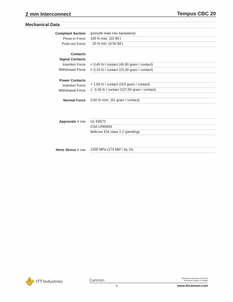
Mechanical Data
UL E8572
CSA LR85691
Bellcore EIA class 1.2 (pending)
1200 MPa (174 klbf / sq. in)
(pressfit male into backplane)
100 N max. (22 lbf.)
20 N min. (4,50 lbf.)
< 0,45 N / contact (45,90 gram / contact)
≥ 0,15 N / contact (15,30 gram / contact)
< 1,50 N / contact (153 gram / contact)
≥ 0,30 N / contact (127,50 gram / contact)
0,60 N nom. (61 gram / contact)
Compliant Section
Press-in Force
Push-out Force
Contacts
Signal Contacts
Insertion Force
Withdrawal Force
Power ContactsInsertion Force
Withdrawal Force
Normal Force
Approvals 4 row
Hertz Stress 4 row
2 mm Interconnect

Dimensions are shown mm (inch)Dimensions subject to change
www.ittcannon.com6
Tempus CBC 20
Shrouds
4 row 5 row
Power Modules Male
4 row wide wall 4 row narrow wall
Power Modules Female
Coding System
Monoblocks
Cable Connectors
Signal Modules Female
4 row solder 4 row press-fit 5 row solder
Signal Modules Male Right-Angle
Ground (e.s.d.) System
Guide Modules
High Power Module
Coaxial Module
Hybrid Modules
System Overview
2 mm Interconnect
Signal Modules Male

Dimensions are shown mm (inch)Dimensions subject to change
www.ittcannon.com7
Tempus CBC 20
1,50 A at 25°C, 1A at 70°C
1000 Vrms
Initial: 5000MΩ, after climatic test: 1000 MΩ45 mΩ maximum
Current Rating
Withstanding Voltage
Insulation Resistance
Contact Resistance
Electrical Data
Contact Pitch
Polarisation
Coding
Housing Material
Termination
Termination p.t.h.
Board Retention
Contact Material
Hertz Stress
Class 1
Plating
Insertion Force
Withdrawal Force
Technical DataMechanical Data
Female Signal Modules - Solder Termination - 4 Row
2,00 x 2,00 (.079 x .079)
By design
With coding keys, see page 64
Liquid Crystal Polymer, UL94V-0 or PPS UL94V-0
Solder tail, tin / lead plated
ø 0,60 (.024), refer to page 73
Pushfit peg or heat stake
Phosphor bronze
1200 MPa (174 klbf / sq. in.)
1000 cycles minimum
Palladium Nickel plus Gold over Nickel
0,45 N (1.6 oz) max. per contact
0,15 N (0,5 oz) min. per contact
• High I/O, 20 contacts per linear centimetre(51 contacts per linear inch)
• High temperature materials, not affected by reflow solder process
• Heat stake or pushfit peg retention
• High performance contacts, high hertz stress, 1000 cycles minimum
• 45° tails for mechanical stability andelectrical performance
• Designed to conform with IEC61076-4-104, EIAis64, IEEE P896 Futurebus+, IEEE P1596 SCI and IEC 917 metric modular order
• Stackable with other TEMPUS modules, with no loss of positions
Features
2 mm Interconnect

Dimensions are shown mm (inch)Dimensions subject to change
www.ittcannon.com8
Tempus CBC 20
Contact in Tube
24 44
48 22
96 11
192 5
Packaging Quantity
192 Contacts
96 Contacts
48 Contacts
24 Contacts
Recommended PCB Hole Pattern,Component Side
Push-fit Peg Version *
After Heat Stake
Heat Stake Version
Performance 1000 mating cycles
All part numbers shown refer to connectorssupplied in trays. For connectors supplied intubes add the designation-VR to the end of thepart number.
Note:
Minimum order quantities apply
* Part numbers in blue letters typeface indicate high runner products: usually available with shorter lead times.
No. of Part Numbers* BoardContacts Pushfit Peg Heat Stake Thickness A B
24 CBC20P00-024FDS1-0-1-002 CBC20P00-024FDS1-0-1 1,60 (.063) 10,00 (.394) 11,95 (.470)
48 CBC20Q00-048FDS1-0-1-002 CBC20Q00-048FDS1-0-1 1,60 (.063) 22,00 (.866) 23,95 (.943)
96 CBC20R00-096FDS1-0-1-002 CBC20R00-096FDS1-0-1 1,60 (.063) 46,00 (1,811) 47,95 (1,888)
192 CBC20S00-192FDS1-0-1-002 CBC20S00-192FDS1-0-1 1,60 (.063) 94,00 (3.701) 95,95 (3.778)
24 CBC20P00-024FDS2-0-1-002 CBC20P00-024FDS2-0-1 2,40 (.094) 10,00 (.394) 11,95 (.470)
48 CBC20Q00-048FDS2-0-1-002 CBC20Q00-048FDS2-0-1 2,40 (.094) 22,00 (.866) 23,95 (.943)
96 CBC20R00-096FDS2-0-1-002 CBC20R00-096FDS2-0-1 2,40 (.094) 46,00 (1.811) 47,95 (1.888)
192 CBC20S00-192FDS2-0-1-002 CBC20S00-192FDS2-0-1 2,40 (.094) 94,00 (3.701) 95,95 (3.778)
* Refer to Design Notes on page 73 for circuit board drill and hole plating details.
Female Signal Modules - Solder Termination - 4 Row
2 mm Interconnect

Dimensions are shown mm (inch)Dimensions subject to change
www.ittcannon.com9
Tempus CBC 20
1,50 A at 25°C, 1 A at 70°C
1000 Vrms
Initial: 5000MΩ, after climatic test: 1000 MΩ45 mΩ maximum
Current Rating
Withstanding Voltage
Insulation Resistance
Contact Resistance
Electrical Data
Contact Pitch
Polarisation
Coding
Housing Material
Termination
Termination p.t.h.
Board Retention
Contact Material
Hertz Stress
Class 1
Plating
Insertion Force
Withdrawal Force
Technical DataMechanical Data
2,00 x 2,00 (.079 x .079)
By design
With coding key, see page 64
Liquid Crystal Polymer, UL94V-0 or PPS, UL94V-0
Eye of the needle compliant section, tin/lead plated
ø 0,70 (.028) refer to page 73
Pushfit peg
Phosphor Bronze
1200 MPa (174 klbf / sq. in.)
1000 cycles minimum
Palladium Nickel plus Gold over Nickel
0,45 N (1.6 oz) max. per contact
0,15 N (0,5 oz) min. per contact
Female Signal Modules - Press Fit Termination - 4 Row
• High I/O, 20 contacts per linear centimetre(51 contacts per linear inch)
• High temperature materials, not affected by reflow solder
• Push fit retention
• High performance contacts, high hertz stress, 1000 cycles minimum
• 45° tails for mechanical stability andelectrical performance
• Designed to conform with IEC 61076-4-104, EIAis64, IEEE P896 Futurebus+, IEEE P1596 SCI and IEC 917 metric modular order
• Stackable with other TEMPUS modules, with no loss of positions
Features
2 mm Interconnect
Dimensions are shown mm (inch)Dimensions subject to change
www.ittcannon.com10
Tempus CBC 20
Recommended PCB Hole Pattern, Component Side
192 Contacts
96 Contacts
48 Contacts
24 Contacts
Detail Press-fit
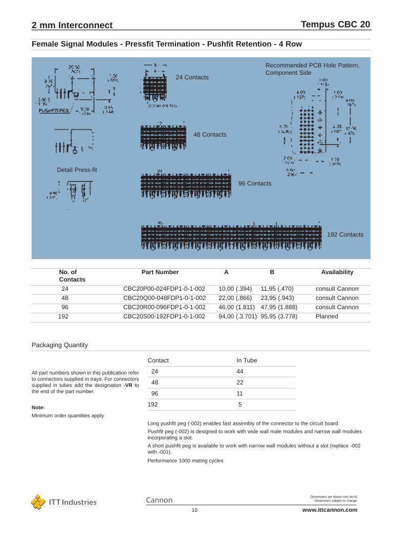
Contact In Tube
24 44
48 22
96 11
192 5
Packaging Quantity
Long pushfit peg (-002) enables fast assembly of the connector to the circuit board.
Pushfit peg (-002) is designed to work with wide wall male modules and narrow wall modulesincorporating a slot.
A short pushfit peg is available to work with narrow wall modules without a slot (replace -002with -001).
Performance 1000 mating cycles
All part numbers shown in this publication referto connectors supplied in trays. For connectorssupplied in tubes add the designation -VR tothe end of the part number.
Note:
Minimum order quantities apply
Female Signal Modules - Pressfit Termination - Pushfit Retention - 4 Row
No. of Part Number A B AvailabilityContacts
24 CBC20P00-024FDP1-0-1-002 10,00 (.394) 11,95 (.470) consult Cannon
48 CBC20Q00-048FDP1-0-1-002 22,00 (.866) 23,95 (.943) consult Cannon
96 CBC20R00-096FDP1-0-1-002 46,00 (1.811) 47,95 (1.888) consult Cannon
192 CBC20S00-192FDP1-0-1-002 94,00 (.3.701) 95,95 (3.778) Planned
2 mm Interconnect

Dimensions are shown mm (inch)Dimensions subject to change
www.ittcannon.com11
4,00 A at 25°C, 3,00A at 70°C
1000 Vrms
Initial: 5000MΩ, after climatic test: 1000 MΩ25 mΩ maximum
Current Rating
Withstanding Voltage
Insulation Resistance
Contact Resistance
Electrical Data
Contact Pitch
Polarisation
Coding
Housing Material
Termination
Termination p.t.h.
Board Retention
Contact Material
Hertz Stress
Class 1
Plating
Insertion Force
Withdrawal Force
Technical DataMechanical Data
2,00 x 2,00 (.079 x .079)
By design
With coding key, see page 64
Liquid Crystal Polymer, UL94V-0 or PPS, UL94V-0
Solder tail, tin / lead plated
ø 0,60 (.024), refer to page 73
Pushfit peg or heat stake
Phosphor bronze
1200 MPa (174 klbf / sq. in.)
1000 cycles minimum
Palladium Nickel plus Gold over Nickel
1,50 N (5,3 oz) max. per contact
0,30 N (1,0 oz) min. per contact
Tempus CBC 20
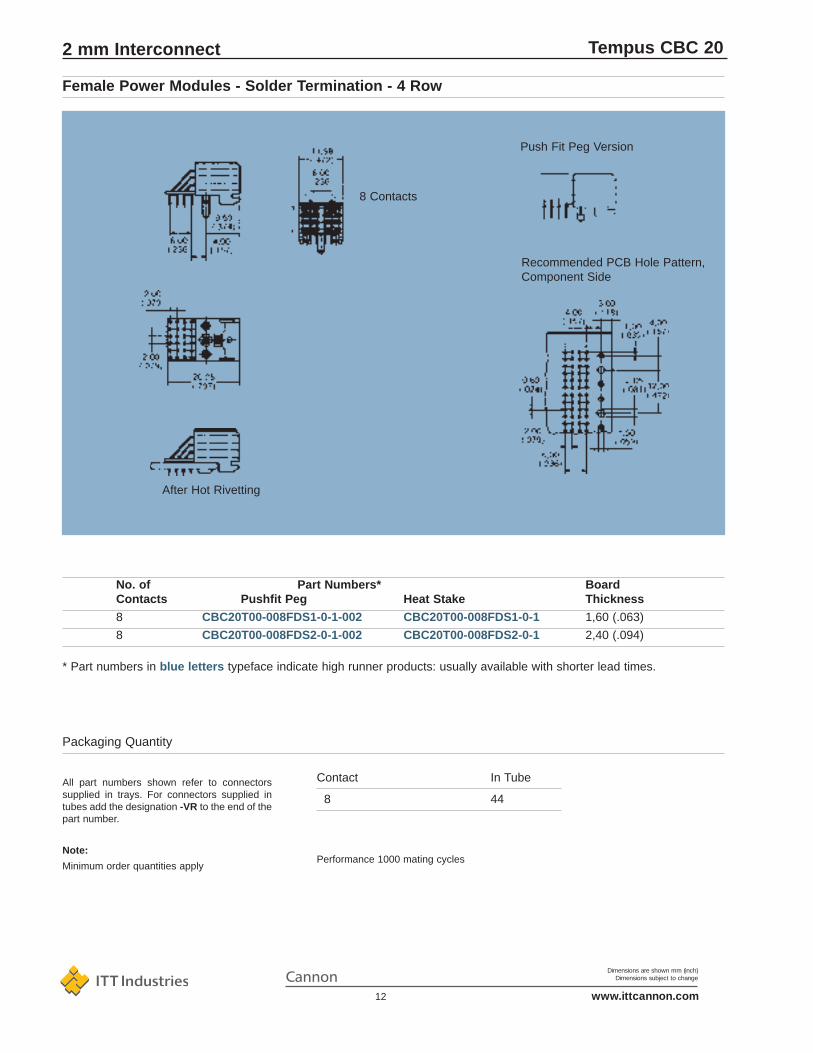
Female Power Modules - Solder Termination - 4 Row
• High temperature materials, not affected by reflow solder process
• 45° legform for optimum mechanicaland electrical performance
• Heat Stake or pushfit peg retention
• High performance contacts, high hertz stress, 1000 cycles minimum
• High I/O, eight contacts in a 12 mm module
• Designed to conform with IEC 48b237, EIAis64, IEEE P896 Futurebus+, IEEE P1596 SCI and IEC 917 metric modular order
• Stackable with other TEMPUS modules, with no loss of positions
Features
2 mm Interconnect
Dimensions are shown mm (inch)Dimensions subject to change
www.ittcannon.com12
Tempus CBC 20
Push Fit Peg Version
Recommended PCB Hole Pattern, Component Side
After Hot Rivetting
8 Contacts
Contact In Tube
8 44
Packaging Quantity
Performance 1000 mating cycles
All part numbers shown refer to connectorssupplied in trays. For connectors supplied intubes add the designation -VR to the end of thepart number.
Note:
Minimum order quantities apply
* Part numbers in blue letters typeface indicate high runner products: usually available with shorter lead times.
No. of Part Numbers* BoardContacts Pushfit Peg Heat Stake Thickness
8 CBC20T00-008FDS1-0-1-002 CBC20T00-008FDS1-0-1 1,60 (.063)
8 CBC20T00-008FDS2-0-1-002 CBC20T00-008FDS2-0-1 2,40 (.094)
Female Power Modules - Solder Termination - 4 Row
2 mm Interconnect

Dimensions are shown mm (inch)Dimensions subject to change
www.ittcannon.com13
4,00 A at 25°C, 3,00 A at 70°C
1000 Vrms
Initial: 5000MΩ, after climatic test: 1000 MΩ25 mΩ maximum
Current Rating
Withstanding Voltage
Insulation Resistance
Contact Resistance
Electrical Data
Contact Pitch
Polarisation
Coding
Housing Material
Termination Press Fit
Termination p.t.h.
Board Retention
Contact Material
Hertz Stress
Class 1
Plating
Insertion Force
Withdrawal Force
Technical DataMechanical Data
2,00 x 2,00 (.079 x .079)
By design
With coding key, see page 64
Liquid Crystal Polymer, UL94V-0 or PPS, UL94V-0
Eye of the needle compliant section, tinlead plated
ø 0,70 (.028) refer to page 73
Pushfit peg
Phosphor Bronze
1200 MPa (174 klbf / sq. in.)
1000 cycles minimum
Palladium Nickel plus Gold over Nickel
1,50 N (1.6 oz) max. per contact
0,30 N (0,5 oz) min. per contact
Tempus CBC 20
Female Power Modules - Press Fit Termination - 4 Row
• 45° tails for mechanical stability andelectrical performance
• High temperature materials, not affected by reflow solder process
• Press fit with push fit retention, solder with heat stake or push fit
• High performance contacts, high hertz stress, 1000 cycles minimum
• Designed to conform with IEC 61076-4-104, EIAis64, IEEE P896 Futurebus+, IEEE P1596 SCI and IEC 917 metric modular order
• Stackable with other TEMPUS modules, with no loss of positions
Features
2 mm Interconnect

Dimensions are shown mm (inch)Dimensions subject to change
www.ittcannon.com14
21,0(.827)
2,0(.079)
3,0(.118)
4,0(.157)
1,0(.039)
4,0(.157)
2,05(.081)
12,(.472)
1,5(.059)
6,0(.236)
2,0(.079)
Recommended PCB Hole Pattern,Component Side
8 Contacts
3,65(.144)
6,0(.236)
11,95(.470)
4,0(.157)
9,5(.374)
6,0(.236)
2,00(.079)
9,3(.366)
Board Retention
push fit peg
PCB Thickness
>1,60 (.063)
Packaging Units
44
Order Number
CBC20T00-008FDP1-0-1-002-VR
Contacts
8
Tempus CBC 20
Female Power Modules - Press Fit Termination - 4 Row
2 mm Interconnect

Dimensions are shown mm (inch)Dimensions subject to change
www.ittcannon.com15
Tempus CBC 20
1,50 A at 25°C, 1,00 A at 70°C
1000 Vrms
Initial: 5000MΩ, after climatic test: 1000 MΩ45 mΩ maximum
Current Rating
Withstanding Voltage
Insulation Resistance
Contact Resistance
Electrical Data
Contact Pitch
Polarisation
Coding
Housing Material
Termination
Termination p.t.h.
Board Guiding Left to Right
Top to Bottom
Board Slot Pitch
Contact Material
Hertz Stress
Class 1
Plating
Insertion Force
Withdrawal Force
Technical DataMechanical Data
2,00 x 2,00 (.079 x .079)
By design
With coding key, see page 64
Liquid Crystal Polymer, UL94V-0 or PPS, UL94V-0
Solder tail, tin / lead plated
ø 0,60 (.024), refer to page 73, 0,50 - 0,80 (.025 - 0,31)
2,50 - 2,50 (.100 - .100)
1,50 - 1,50 (.060 - .060)
16,00 (.630) min.
Brass
1200 MPa (174 klbf / sq. in.)
1000 cycles minimum
Palladium Nickel plus Gold over Nickel
0,45 N (1.6 oz) max. per contact
0,15 N (0,5 oz) min. per contact
Male Signal Modules - Solder Termination - 4 Row
• High temperature materials, not affected by reflow solder process
• Wide wall design for system tolerant2,50 (.098) out-of-centre board insertion
• Sequential mating provides live insertion capability
• High performance contacts, high hertz stress, 1000 cycles minimum
• High I/O, 20 contacts per linear centimetre (51 contacts per linear inch)
• Designed to conform with IEC61076-4-104, EIAis64, IEEE P896 Futurebus+, IEEE P1596 SCI and IEC 917 metric modular order
• Stackable with other TEMPUS modules, with no loss of positions
Features
2 mm Interconnect

Dimensions are shown mm (inch)Dimensions subject to change
www.ittcannon.com16
Tempus CBC 20
Recommended PCB Hole Pattern, Component Side
192 Contacts
96 Contacts
48 Contacts
24 Contacts
No. of
Contacts A B
24 10,00 (.394) 11,95 (.470)
48 22,00 (.866) 23,95 (.943)
96 46,00 (1.811) 47,95 (1.888)
192 94,00 (3.701) 95,95 (3.778)
Male Signal Modules - Solder Termination - 4 Row
2 mm Interconnect

Dimensions are shown mm (inch)Dimensions subject to change
www.ittcannon.com17
Tempus CBC 20
(Continued on next page)
* Part numbers in blue letters typeface indicate high runner products: usually available with shorter lead times.
No. of Board Contact Arrangement RowContacts Part Number * Thickness a b c d
24 CBC20A00-024WDS1-1-1 3,20 (.125) 5,00 (.197) 5,00 (.197) 5,00 (.197) 5,00 (.197)
24 CBC20A00-024WDS1-2-1 3,20 (.125) 6,50 (.256) 5,00 (.197) 5,00 (.197) 5,00 (.197)
24 CBC20A00-024WDS1-3-1 3,20 (.125) 6,50 (.256) 5,75 (.226) 5,75 (.226) 6,50 (.256)
24 CBC20A00-024WDS1-4-1 3,20 (.125) 7,25 (.285) 6,50 (.256) 6,50 (.256) 7,25 (.285)
24 CBC20A00-024WDS1-5-1 3,20 (.125) 6,50 (.256) 6,50 (.256) 6,50 (.256) 6,50 (.256)
24 CBC20A00-02WDS1-8-1 3,20 (.125) 5,75 (.226) 7,25 (.285) 5,75 (.226) 5,75 (.226)
24 CBC20A00-024WDS2-1-1 2,40 (.094) 5,00 (.197) 5,00 (.197) 5,00 (.197) 5,00 (.197)
24 CBC20A00-024WDS2-2-1 2,40 (.094) 6,50 (.256) 5,00 (.197) 5,00 ( .197) 5,00 (.197)
24 CBC20A00-024WDS2-3-1 2,40 (.094) 6,50 (.256) 5,75 (.226) 5,75 (.226) 6,50 (.256)
24 CBC20A00-024WDS2-4-1 2,40 (.094) 7,25 (.285) 6,50 (.256) 6,50 (.256) 7,25 (.285)
24 CBC20A00-024WDS2-5-1 2,40 (.940) 6,50 (.256) 6,50 (.256) 6,50 (.256) 6,50 (.256)
24 CBC20A00-024WDS2-8-1 2,40 (.094) 5,75 (.226) 7,25 (.285) 5,75 (.226) 5,75 (.226)
48 CBC20B00-048WDS1-1-1 3,20 (.125) 5,00 (.197) 5,00 (.197) 5,00 (.197) 5,00 (.197)
48 CBC20B00-048WDS1-2-1 3,20 (.125) 6,50 (.256) 5,00 (.197) 5,00 (.197) 5,00 (.197)
48 CBC20B00-048WDS1-3-1 3,20 (.125) 6,50 (.256) 5,75 (.226) 5,75 (.226) 6,50 (.256)
48 CBC20B00-048WDS1-4-1 3,20 (.125) 7,25 (.285) 6,50 (.256) 6,50 (.256) 7,25 (.285)
48 CBC20B00-048WDS1-5-1 3,20 (.125) 6,50 (.256) 6,50 (.256) 6,50 (.256) 6,50 (.256)
48 CBC20B00-048WDS1-8-1 3,20 (.125) 5,75 (.226) 7,25 (.285) 5,75 (.226) 5,75 (.226)
48 CBC20B00-048WDS2-1-1 2,40 (.094) 5,00 (.197) 5,00 (.197) 5,00 (.197) 5,00 (.197)
48 CBC20B00-048WDS2-2-1 2,40 (.094) 6,50 (.256) 5,00 (.197 5,00 (.197) 5,00 (.197)
48 CBC20B00-048WDS2-3-1 2,40 (.094) 6,50 (.256) 5,75 (.226) 5,75 (.226) 6,50 (.256)
48 CBC20B00-048WDS2-4-1 2,40 (.094) 7,25 (.285) 6,50 (.256) 6,50 (.256) 7,25 (.285)
48 CBC20B00-048WDS2-5-1 2,40 (.094) 6,50 (.256) 6,50 (.256) 6,50 (.256) 6,50 (.256)
48 CBC20B00-048WDS2-8-1 2,40 (.094) 5,75 (.226) 7,25 (.285) 5,75 (.226) 5,75 (.226)
96 CBC20C00-096WDS1-1-1 3,20 (.125) 5,00 (.197) 5,00 (.197) 5,00 (.197) 5,00 (.197)
96 CBC20C00-096WDS1-2-1 3,20 (.125) 6,50 (.256) 5,00 (.197) 5,00 (.197) 5,00 (.197)
96 CBC20C00-096WDS1-3-1 3,20 (.125) 6,50 (.256) 5,75 (.226) 5,75 (.226) 6,50 (.256)
96 CBC20C00-096WDS1-4-1 3,20 (.125) 7,25 (.285) 6,50 (.256) 6,50 (.256) 7,25 (285)
96 CBC20C00-096WDS1-5-1 3,20 (.125) 6,50 (.256) 6,50 (.256) 6,50 (.256) 6,50 (.256)
96 CBC20C00-096WDS1-8-1 3,20 (.125) 5,75 (.226) 7,25 (.285) 5,75 (.226) 5,75 (.226)
96 CBC20C00-096-WDS2-1-1 2,40 (.094) 5,00 (.197) 5,00 (.197) 5,00 (.197) 5,00 (.197)
96 CBC20C00-096WDS2-2-1 2,40 (.094) 6,50 (.256) 5,00 (.197) 5,00 (.197) 5,00 (.197)
96 CBC20C00-096WDS2-3-1 2,40 (.094) 6,50 (.256) 5,75 (.226) 5,75 (.226) 6,50 (.256)
96 CBC20C00-096WDS2-4-1 2,40 (.094) 7,25 (.285) 6,50 (.256) 6,50 (.256) 7,25 (.285)
96 CBC20C00-096WDS2-5-1 2,40 (.094) 6,50 (.256) 6,50 (.256) 6,50 (.256) 6,50 (.256)
96 CBC20C00-096WDS2-8-1 2,40 (.094) 5,75 (.226) 7,25 (.285) 5,75 (.226) 5,75 (.226)
192 CBC20D00-192WDS1-1-1 3,20 (.125) 5,00 (.197) 5,00 (.197) 5,00 (.197) 5,00 (.197)
192 CBC20D00-192WDS1-2-1 3,20 (.125) 6,50 (.256) 5,00 (.197) 5,00 (.197) 5,00 (.197)
192 CBC20D00-192WDS1-3-1 3,20 (.125) 6,50 (.256) 5,75 (.226) 5,75 (.226) 6,50 (.256)
192 CBC20D00-192WDS1-4-1 3,20 (.125) 7,25 (.285) 6,50 (.256) 6,50 (.256) 7,25 (285)
Male Signal Modules - Solder Termination - 4 Row
2 mm Interconnect
Dimensions are shown mm (inch)Dimensions subject to change
www.ittcannon.com18
Tempus CBC 20
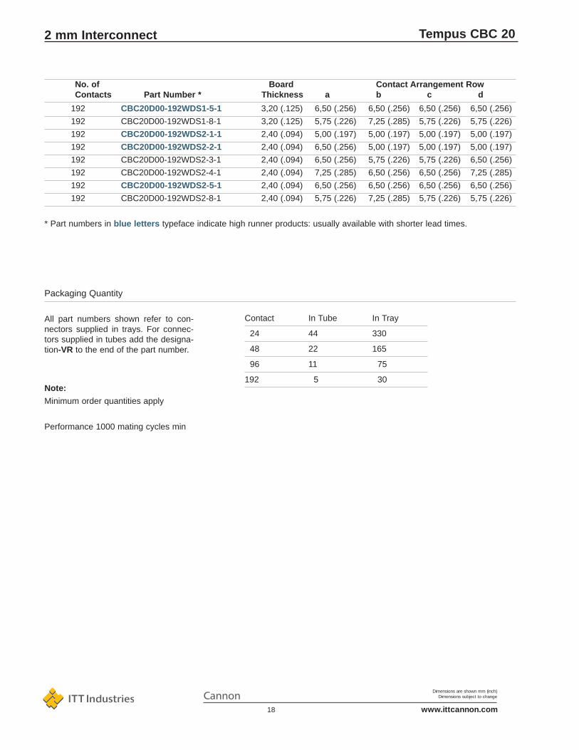
* Part numbers in blue letters typeface indicate high runner products: usually available with shorter lead times.
Contact In Tube In Tray
24 44 330
48 22 165
96 11 75
192 5 30
Packaging Quantity
All part numbers shown refer to con-nectors supplied in trays. For connec-tors supplied in tubes add the designa-tion-VR to the end of the part number.
Note:
Minimum order quantities apply
Performance 1000 mating cycles min
192 CBC20D00-192WDS1-5-1 3,20 (.125) 6,50 (.256) 6,50 (.256) 6,50 (.256) 6,50 (.256)
192 CBC20D00-192WDS1-8-1 3,20 (.125) 5,75 (.226) 7,25 (.285) 5,75 (.226) 5,75 (.226)
192 CBC20D00-192WDS2-1-1 2,40 (.094) 5,00 (.197) 5,00 (.197) 5,00 (.197) 5,00 (.197)
192 CBC20D00-192WDS2-2-1 2,40 (.094) 6,50 (.256) 5,00 (.197) 5,00 (.197) 5,00 (.197)
192 CBC20D00-192WDS2-3-1 2,40 (.094) 6,50 (.256) 5,75 (.226) 5,75 (.226) 6,50 (.256)
192 CBC20D00-192WDS2-4-1 2,40 (.094) 7,25 (.285) 6,50 (.256) 6,50 (.256) 7,25 (.285)
192 CBC20D00-192WDS2-5-1 2,40 (.094) 6,50 (.256) 6,50 (.256) 6,50 (.256) 6,50 (.256)
192 CBC20D00-192WDS2-8-1 2,40 (.094) 5,75 (.226) 7,25 (.285) 5,75 (.226) 5,75 (.226)
No. of Board Contact Arrangement RowContacts Part Number * Thickness a b c d
2 mm Interconnect

Dimensions are shown mm (inch)Dimensions subject to change
www.ittcannon.com19
Tempus CBC 20
1,50 A at 25°C; 1,00 A at 70°C
1000 Vrms
Initial: 5000MΩ; after climatic test: 1000 MΩ45 mΩ maximum
Current Rating
Withstanding Voltage
Insulation Resistance
Contact Resistance
Electrical Data
Contact Pitch
Polarisation
Coding
Housing Material
Termination
Termination p.t.h.
Board Guiding Left to Right
Top to Bottom
Board Slot Pitch
Contact Material
Hertz Stress
Class 1
Plating
Insertion Force
Withdrawal Force
Technical DataMechanical Data
2,00 x 2,00 (.079 x .079)
By design
With coding key, see page 64
Liquid Crystal Polymer, UL94V-0 or PPS, UL94V-0
Eye of needle compliant section, tin/lead plated
ø 0,70 (.028), refer to page 73
2,50 - 2,50 (.100 - .100)
1.50 - 1,50 (.060 - .060)
16,00 (.630) min.
Phosphor bronze
1200 MPa (174 klbf / sq. in.)
1000 cycles minimum
Palladium Nickel plus Gold over Nickel
0,45 N (1.6 oz) max. per contact
0,15 N (0,5 oz) min. per contact
• High temperature materials, not affected by reflow solder process
• Wide wall design for system tolerant2,50 (.098) out-of-centre board insertion
• Sequential mating provides live insertion capability
• High performance contacts, high hertz stress, 1000 cycles minimum
• High I/O, 20 contacts per linear centimetre (51 contacts per linear inch)
• Designed to conform with IEC61076-4-104, EIAis64, IEEE P896 Futurebus+, IEEE P1596 SCI and IEC 917 metric modular order
• Stackable with other TEMPUS modules, with no loss of positions
Features
Male Signal Modules - Wide Wall - Pressfit Termination - 4 Row
2 mm Interconnect

Dimensions are shown mm (inch)Dimensions subject to change
www.ittcannon.com20
Tempus CBC 20
Recommended PCB Hole Pattern,Component Side
192 Contacts
96 Contacts
48 Contacts
24 Contacts
No. of
Contacts A B
24 10.00 (.394) 11,95 (.470)
48 22,00 (.866) 23,95 (.943)
96 46,00 (1.811) 47,95 (1.888)
192 94,00 (3.701) 95,95 (3.778)
(Continued on next page)
* Part numbers in blue letters typeface indicate high runner products: usually available with shorter lead times.
Male Signal Modules - Wide Wall - Pressfit Termination - 4 Row
No. of Part numbers* Termination Contact Arrangement RowContacts a b c d
24 CBC20A00-024WDP1-1-1 Press-fit, 4,30 (.169) tail 5,00 (.197) 5,00 (.197) 5,00 (.197) 5,00 (.197)
24 CBC20A00-024WDP1-2-1 Press-fit, 4,30 (.169) tail 6,50 (.256) 5,00 (.197) 5,00 (.197) 5,00 (.197)
24 CBC20A00-024WDP1-3-1 Press-fit, 4,30 (.169) tail 6,50 (.256) 5,75 (.226) 5,75 (.226) 6,50 (.256)
24 CBC20A00-024WDP1-4-1 Press-fit, 4,30 (.169) tail 7,25 (.285) 6,50 (.256) 6,50 (.256) 7,25 (.285)
24 CBC20A00-024WDP1-5-1 Press-fit, 4,30 (.169) tail 6,50 ( .256) 6,50 (.256) 6,50 (.256) 6,50 (.256)
24 CBC20A00-024WDP1-8-1 Press-fit, 4,30 (.169) tail 5,75 (.226) 7,25 (.285) 5,75 (.226) 5,75 (.226)
24 CBC20A00-024WDU1-1-1 Press-fit, 13,60 (.535) tail 5,00 (.197) 5,00 (.197) 5,00 (.197) 5,00 (.197)
2 mm Interconnect

Dimensions are shown mm (inch)Dimensions subject to change
www.ittcannon.com21
Tempus CBC 20
(Continued on next page)
* Part numbers in blue letters typeface indicate high runner products: usually available with shorter lead times.
Male Signal Modules - Wide Wall - Pressfit Termination - 4 Row
No. of Part numbers* Termination Contact Arrangement RowContacts a b c d
24 CBC20A00-024WDU1-2-1 Press-fit, 13,60 (.535) tail 6,50 (.256) 5,00 (.197) 5,00 (.197) 5,00 (.197)
24 CBC20A00-024WDU-1-3-1 Press-fit, 13,60 (.535) tail 6,50 (.256) 5,75 (.226) 5,75 (.226) 6,50 (.256)
24 CBC20A00-024WDU1-4-1 Press-fit, 13,60 (.535) tail 7,25 (.285) 6,50 (.256) 6,50 (.256) 7,25 (.285)
24 CBC20A00-024WDU1-5-1 Press-fit, 13,60 (.535) tail 6,50 (.256) 6,50 (.256) 6,50 (.256) 6,50 (.256)
24 CBC20A00-024WDU1-8-1 Press-fit, 13,60 (.535) tail 5,75 (.226) 7,25 (.285) 5,75 (.226) 5,75 (.226)
24 CBC20A00-024WDV2-1-1 Press-fit, 17,00 (.669) tail 5,00 (.197) 5,00 (.197) 5,00 (.197) 5,00 (.197)
24 CBC20A00-024WDV2-2-1 Press-fit, 17,00 (.669) tail 6,50 (.256) 5,00 (.197) 5,00 (.197) 5,00 (.197)
24 CBC20A00-024WDV2-3-1 Press-fit, 17,00 (.669) tail 6,50 (.256) 5,75 (.226) 5,75 (.226) 6,50 (.256)
24 CBC20A00-024WDV2-4-1 Press-fit, 17,00 (.669) tail 7,25 (.285) 6,50 (.256) 6,50 (.256) 7,25 (.285)
24 CBC20A00-024WDV2-5-1 Press-fit, 17,00 (.669) tail 6,50 (.256) 6,50 (.256) 6,50 (.256) 6,50 (.256)
24 CBC20A00-024WDV2-8-1 Press-fit, 17,00 (.669) tail 5,75 (.226) 7,25 (.285) 5,75 (.226) 5,75 (.226)
48 CBC20B00-048WDP1-1-1 Press-fit, 4,30 (.169) tail 5,00 (.197) 5,00 (.197) 5,00 (.197) 5,00 (.197)
48 CBC20B00-048WDP1-2-1 Press-fit, 4,30 (.169) tail 6,50 (.256) 5,00 (.197) 5,00 (.197) 5,00 (.197)
48 CBC20B00-048WDP1-3-1 Press-fit, 4,30 (.169) tail 6,50 (.256) 5,75 (.226) 5,75 (.226) 6,50 (.256)
48 CBC20B00-048WDP1-4-1 Press-fit, 4,30 (.169) tail 7,25 (.285) 6,50 (.256) 6,50 (.256) 7,25 (.285)
48 CBC20B00-048WDP1-5-1 Press-fit, 4,30 (.169) tail 6,50 (.256) 6,50 (.256) 6,50 (.256) 6,50 (.256)
48 CBC20B00-048WDP1-8-1 Press-fit, 4,30 (.169) tail 5,75 (.226) 7,25 (.285) 5,75 (.226) 5,75 (.226)
48 CBC20B00-048WDU1-1-1 Press-fit, 13,60 (.535) tail 5,00 (.197) 5,00 (.197) 5,00 (.197) 5,00 (.197)
48 CBC20B00-048WDU1-2-1 Press-fit, 13,60 (.535) tail 6,50 (.256) 5,00 (.197) 5,00 (.197) 5,00 (.197)
48 CBC20B00-048WDU1-3-1 Press-fit, 13,60 (.535) tail 6,50 (.256) 5,75 (.226) 5,75 (.226) 6,50 (.256)
48 CBC20B00-048WDU1-4-1 Press-fit, 13,60 (.535) tail 7,25 (.285) 6,50 (.256) 6,50 (.256) 7,25 (.285)
48 CBC20B00-048WDU1-5-1 Press-fit, 13,60 (.535) tail 6,50 (.256) 6,50 (.256) 6,50 (.256) 6,50 (.256)
48 CBC20B00-048WDU1-8-1 Press-fit, 13,60 (.535) tail 5,75 (.226) 7,25 (.285) 5,75 (.226) 5,75 (.226)
48 CBC20B00-048WDV2-1-1 Press-fit, 17,00 (.669) tail 5,00 (.197) 5,00 (.197) 5,00 (.197) 5,00 (.197)
48 CBC20B00-048WDV2-2-1 Press-fit, 17,00 (.669) tail 6,50 (.256) 5,00 (.197) 5,00 (.197) 5,00 (.197)
48 CBC20B00-048WDV2-3-1 Press-fit, 17,00 (.669) tail 6,50 (.256) 5,75 (.226) 5,75 (.226) 6,50 (.256)
48 CBC20B00-048WDV2-4-1 Press-fit, 17,00 (.669) tail 7,25 (.285) 6,50 (.256) 6,50 (.256) 7,25 (.285)
48 CBC20B00-048WDV2-5-1 Press-fit, 17,00 (.669) tail 6,50 (.256) 6,50 (.256) 6,50 (.256) 6,50 (.256)
48 CBC20B00-048WDV2-8-1 Press-fit, 17,00 (.669) tail 5,75 (.226) 7,25 (.285) 5,75 (.226) 5,75 (.226)
96 CBC20C00-096WDP1-1-1 Press-fit, 4,30 (.169) tail 5,00 (.197) 5,00 (.197) 5,00 (.197) 5,00 (.197)
96 CBC20C00-096WDP1-2-1 Press-fit, 4,30 (.169) tail 6,50 (.256) 5,00 (.197) 5,00 (.197) 5,00 (.197)
96 CBC20C00-096WDP1-3-1 Press-fit, 4,30 (.169) tail 6,50 (.256) 5,75 (.226) 5,75 (.226) 6,50 (.256)
96 CBC20C00-096WDP1-4-1 Press-fit, 4,30 (.169) tail 7,25 (.285) 6,50 (.256) 6,50 (.256) 7,25 (.285)
96 CBC20C00-096WDP1-5-1 Press-fit, 4,30 (.169) tail 6,50 (.256) 6,50 (.256) 6,50 (.256) 6,50 (.256
96 CBC20C00-096WDP1-8-1 Press-fit, 4,30 (.169) tail 5,75 (.226) 7,25 (.285) 5,75 (.226) 5,75 (.226)
96 CBC20C00-096WDU1-1-1 Press-fit, 13,60 (.535) tail 5,00 (.197) 5,00 (.197) 5,00 (.197) 5,00 (.197)
96 CBC20C00-096WDU1-2-1 Press-fit, 13,60 (.535) tail 6,50 (.256) 5,00 (.197) 5,00 (.197) 5,00 (.197)
2 mm Interconnect

Dimensions are shown mm (inch)Dimensions subject to change
www.ittcannon.com22
Tempus CBC 20
Performance 1000 mating cycles min. Contacts In Tube In Tray
24 44 330
48 22 165
96 11 75
192 5 30
Packaging Quantity
All part numbers shown refer to connectors supplied in trays. For connectorssupplied in tubes add the designation -VR to the end of the part number.
Performance 1000 mating cycles min.
Note:Minimum order quantities apply
* Part numbers in blue letters typeface indicate high runner products: usually available with shorter lead times.
No. of Part numbers* Termination Contact Arrangement RowContacts a b c d
96 CBC20B00-096WDU1-3-1 Press-fit, 13,60 (.535) tail 6,50 (.256) 5,75 (.226) 5,75 (.226) 6,50 (.256)
96 CBC20B00-096WDU1-4-1 Press-fit, 13,60 (.535) tail 7,25 (.285) 6,50 (.256) 6,50 (.256) 7,25 (.285)
96 CBC20B00-096WDU1-5-1 Press-fit, 13,60 (.535) tail 6,50 (.256) 6,50 (.256) 6,50 (.256) 6,50 (.256)
96 CBC20B00-096WDU1-8-1 Press-fit, 13,60 (.535) tail 5,75 (.226) 7,25 (.285) 5,75 (.226) 5,75 (.226)
96 CBC20B00-096WDV2-1-1 Press-fit, 17,00 (.669) tail 5,00 (.197) 5,00 (.197) 5,00 (.197) 5,00 (.197)
96 CBC20B00-096WDV2-2-1 Press-fit, 17,00 (.669) tail 6,50 (.256) 5,00 (.197) 5,00 (.197) 5,00 (.197)
96 CBC20B00-096WDV2-3-1 Press-fit, 17,00 (.669) tail 6,50 (.256) 5,75 (.226) 5,75 (.226) 6,50 (.256)
96 CBC20B00-096WDV2-4-1 Press-fit, 17,00 (.669) tail 7,25 (.285) 6,50 (.256) 6,50 (.256) 7,25 (.285)
96 CBC20B00-096WDV2-5-1 Press-fit, 17,00 (.669) tail 6,50 (.256) 6,50 (.256) 6,50 (.256) 6,50 (.256)
96 CBC20B00-096WDV2-8-1 Press-fit, 17,00 (.669) tail 5,75 (.226) 7,25 (.285) 5,75 (.226) 5,75 (.226)
192 CBC20B00-192WDP1-1-1 Press-fit, 4,30 (.169) tail 5,00 (.197) 5,00 (.197) 5,00 (.197) 5,00 (.197)
192 CBC20B00-192WDP1-2-1 Press-fit, 4,30 (.169) tail 6,50 (.256) 5,00 (.197) 5,00 (.197) 5,00 (.197)
192 CBC20B00-192WDP1-3-1 Press-fit, 4,30 (.169) tail 6,50 (.256) 5,75 (.226) 5,75 (.226) 6,50 (.256)
192 CBC20B00-192WDP1-4-1 Press-fit, 4,30 (.169) tail 7,25 (.285) 6,50 (.256) 6,50 (.256) 7,25 (.285)
192 CBC20B00-192WDP1-5-1 Press-fit, 4,30 (.169) tail 6,50 (.256) 6,50 (.256) 6,50 (.256) 6,50 (.256)
192 CBC20B00-192WDP1-8-1 Press-fit, 4,30 (.169) tail 5,75 (.226) 7,25 (.285) 5,75 (.226) 5,75 (.226)
192 CBC20B00-192WDU1-1-1 Press-fit, 13,60 (.535) tail 5,00 (.197) 5,00 (.197) 5,00 (.197) 5,00 (.197)
192 CBC20B00-192WDU1-2-1 Press-fit, 13,60 (.535) tail 6,50 (.256) 5,00 (.197) 5,00 (.197) 5,00 (.197)
192 CBC20B00-192WDU1-3-1 Press-fit, 13,60 (.535) tail 6,50 (.256) 5,75 (.226) 5,75 (.226) 6,50 (.256)
192 CBC20B00-192WDU1-4-1 Press-fit, 13,60 (.535) tail 7,25 (.285) 6,50 (.256) 6,50 (.256) 7,25 (.285)
192 CBC20B00-192WDU1-5-1 Press-fit, 13,60 (.535) tail 6,50 (.256) 6,50 (.256) 6,50 (.256) 6,50 (.256
192 CBC20B00-192WDU1-8-1 Press-fit, 13,60 (.535) tail 5,75 (.226) 7,25 (.285) 5,75 (.226) 5,75 (.226)
192 CBC20B00-192WDV2-1-1 Press-fit, 17,00 (.669) tail 5,00 (.197) 5,00 (.197) 5,00 (.197) 5,00 (.197)
192 CBC20B00-192WDV2-2-1 Press-fit, 17,00 (.669) tail 6,50 (.256) 5,00 (.197) 5,00 (.197) 5,00 (.197)
192 CBC20B00-192WDV2-3-1 Press-fit, 17,00 (.669) tail 6,50 (.256) 5,75 (.226) 5,75 (.226) 6,50 (.256)
192 CBC20B00-192WDV2-4-1 Press-fit, 17,00 (.669) tail 7,25 (.285) 6,50 (.256) 6,50 (.256) 7,25 (.285)
192 CBC20B00-192WDV2-5-1 Press-fit, 17,00 (.669) tail 6,50 (.256) 6,50 (.256) 6,50 (.256) 6,50 (.256)
192 CBC20B00-192WDV2-8-1 Press-fit, 17,00 (.669) tail 5,75 (.226) 7,25 (.285) 5,75 (.226) 5,75 (.226)
Male Signal Modules - Wide Wall - Pressfit Termination - 4 Row
2 mm Interconnect

Dimensions are shown mm (inch)Dimensions subject to change
www.ittcannon.com23
Tempus CBC 20
4,00 A at 25°C, 3,00 A at 70°C
1000 Vrms
Initial: 5000MΩ, after climatic test: 1000 MΩ25 mΩ maximum
Current Rating
Withstanding Voltage
Insulation Resistance
Contact Resistance
Electrical Data
Contact Pitch
Polarisation
Coding
Housing Material
Termination Solder
Termination p.t.h. (solder)
Termination Press-fit
Termination p.t.h. (press-fit)
Board Guiding Left to Right
Top to Bottom
Board Slot Pitch
Contact Material
Hertz Stress
Class 1
Plating
Insertion Force
Withdrawal Force
Technical DataMechanical Data
2,00 x 2,00 (.079 x .079)
By design
With coding key, see page 64
Liquid Crystal Polymer, UL94V-0 or PPS, UL94V-0
Solder tail, tin/lead plated
ø 0,60 (.024)
Eye of needle compliant section, tin/lead plated
ø 0,70 (.028), refer to page 73
2,50 - 2,50 (.100 - .100)
1,50 - 1,50 (.060 - .060)
16,00 (.630) min.
Press-fit contact: Phosphor bronze, Solder contact: Brass
1200 MPa (174 klbf / sq. in.)
1000 cycles minimum
Palladium Nickel plus Gold over Nickel
1,50 N (5,3 oz) max. per contact
0,30 N (1,0 oz) min. per contact
• High temperature materials, not affected by reflow solder process
• Wide wall design for system tolerant 2,50 (.098) out-of-centre board insertion
• Sequential mating provides liveinsertion capability
• High performance contacts, high hertz stress, 1000 cycles minimum
• High I/O, eight power contacts in a 12 mm module
• Designed to conform with IEC61076-4-104, EIAis64, IEEE P896 Futurebus+, IEEE P1596 SCI and IEC 917 metric modular order
• Stackable with other TEMPUS modules, with no loss of positions
Features
Male Power Modules - Wide Wall - Solder or Pressfit Termination - 4 Row
2 mm Interconnect

Dimensions are shown mm (inch)Dimensions subject to change
www.ittcannon.com24
Tempus CBC 20
Recommended P.C.B. Hole Pattern,Component Side
Recommended P.C.B. Hole Pattern,Component Side
Refer to design notes on page 73 for circuit board drill and hole plating details.
Male Power Modules - Wide Wall - Solder or Pressfit Termination - 4 Row
2 mm Interconnect

Dimensions are shown mm (inch)Dimensions subject to change
www.ittcannon.com25
Tempus CBC 20
Contact In Tube In Tray
8 44 330
Packaging Quantity
All part numbers shown refer to con-nectors supplied in trays. For connec-tors supplied in tubes add the designa-tion -VR to the end of the part number.
Note:
Minimum order quantities apply
Performance 1000 mating cycles min
* Part numbers in blue letters typeface indicate standard products: usually available with shorter lead times.
Male Power Modules - Wide Wall - Solder or Pressfit Termination - 4 Row
No. of Part Number* Termination Contact Arrangement RowContacts a b c d
8 CBC20J00-008WDP1-4-1 Press-fit 4,30 (.169) Tail 7,25 (.285) 6,50 (.256) 6,50 (.256) 7,25 (.285)
8 CBC20J00-008WDP1-5-1 Press-fit 4,30 (.169) Tail 6,50 (.256) 6,50 (.256) 6,50 (.256) 6,50 (.256)
8 CBC20J00-008WDP1-6-1 Press-fit 4,30 (.169) Tail 8,00 (.315) 8,00 (.315) 7,25 (.285) 6,50 (.256)
8 CBC20J00-008WDP1-7-1 Press-fit 4,30 (.169) Tail 6,50 (.256) 8,00 (.315) 6,50 (.256) 6,50 (.256)
8 CBC20J00-008WDU1-4-1 Press-fit 13,60 (.535) Tail 7,25 (.285) 6,50 (.256) 6,50 (.256) 7,25 (.285)
8 CBC20J00-008WDU1-5-1 Press-fit 13,60 (.535) Tail 6,50 (.256) 6,50 (.256) 6,50 (.256) 6,50 (.256)
8 CBC20J00-008WDU1-6-1 Press-fit 13,60 (.535) Tail 8,00 (.315) 8,00 (.315) 7,25 (.285) 6,50 (.256)
8 CBC20J00-008WDU1-7-1 Press-fit 13,60 (.535) Tail 6,50 (.256) 8,00 (.315) 6,50 (.256) 6,50 (.256)
8 CBC20J00-008WDV2-4-1 Press-fit 17,00 (.669) Tail 7,25 (.285) 6,50 (.256) 6,50 (.256) 7,25 (.285)
8 CBC20J00-008WDV2-5-1 Press-fit 17,00 (.669) Tail 6,50 (.256) 6,50 (.256) 6,50 (.256) 6,50 (.256)
8 CBC20J00-008WDV2-6-1 Press-fit 17,00 (.669) Tail 8,00 (.315) 8,00 (.315) 7,25 (.285) 6,50 (.256)
8 CBC20J00-008WDV2-7-1 Press-fit 17,00 (.669) Tail 6,50 (.256) 8,00 (.315) 6,50 (.256) 6,50 (.256)
8 CBC20J00-008WDS1-4-1 Solder Tail for 3,20 (.125) Board 7,25 (.285) 6,50 (.256) 6,50 (.256) 7,25 (.285)
8 CBC20J00-008WDS1-5-1 Solder Tail for 3,20 (.125) Board 6,50 (.256) 6,50 (.256) 6,50 (.256) 6,50 (.256)
8 CBC20J00-008WDS1-6-1 Solder Tail for 3,20 (.125) Board 8,00 (.315) 8,00 (.315) 7,25 (.285) 6,50 (.256)
8 CBC20J00-008WDS1-7-1 Solder Tail for 3,20 (.125) Board 6,50 (.256) 8,00 (.315) 6,50 (.256) 6,50 (.256)
8 CBC20J00-008WDS2-4-1 Solder Tail for 2,40 (.094) Board 7,25 (.285) 6,50 (.256) 6,50 (.256) 7,25 (.285)
8 CBC20J00-008WDS2-5-1 Solder Tail for 2,40 (.094) Board 6,50 (.256) 6,50 (.256) 6,50 (.256) 6,50 (.256)
8 CBC20J00-008WDS2-6-1 Solder Tail for 2,40 (.094) Board 8,00 (.315) 8,00 (.315) 7,25 (.285) 6,50 (.256)
8 CBC20J00-008WDS2-7-1 Solder Tail for 2,40 (.094) Board 6,50 (.256) 8,00 (.315) 6,50 (.256) 6,50 (.256)
2 mm Interconnect

Dimensions are shown mm (inch)Dimensions subject to change
www.ittcannon.com26
Tempus CBC 20
1,50 A at 25°C; 1 A at 70°C
1000 Vrms
Initial: 5000MΩ; after climatic test: 1000 MΩ45 mΩ maximum
Current Rating
Withstanding Voltage
Insulation Resistance
Contact Resistance
Electrical Data
Contact Pitch
Polarisation
Coding
Housing Material
Termination
Termination p.t.h.
Board Retention
Contact Material
Hertz Stress
Class 1
Plating
Insertion Force
Withdrawal Force
Technical DataMechanical Data
2,00 x 2,00 (.079 x .079)
By design
With coding key, see page 64
Liquid Crystal Polymer, UL94V-0 or PPS, UL94V-0
Solder tail, tin/lead plated
ø 0,60 (.024) refer to page 73
Pushfit peg or heat stake
Phosphor Bronze
1200 MPa (174 klbf / sq. in.)
1000 cycles minimum
Palladium Nickel plus Gold over Nickel
0,45 N (1.6 oz) max. per contact
0,15 N (0,5 oz) min. per contact
Female Signal Modules - Solder Termination - 5 Row
• High I/O, 25 contacts per linear centimetre(63 contacts per linear inch)
• High temperature materials, not affected by reflow solder
• Heatstake or push fit retention
• High performance contacts, high hertz stress, 1000 cycles minimum
• 45° tails for mechanical stability andelectrical performance
• Designed to conform with IEC61076-4-104, EIAis64, IEEE P896 Futurebus+, IEEE P1596 SCI and IEC 917 metric modular order
• Stackable with other TEMPUS modules, with no loss of positions
Features
2 mm Interconnect

Dimensions are shown mm (inch)Dimensions subject to change
www.ittcannon.com27
Tempus CBC 20
4,00(.157)
9,50(.374)
8,00(.315)
2,00(.079)
2,00(.079)
48
24
1
112
23,00(.906)
23,95(.943)
47,95(1.888)
95,95(3.778)
Recommended PCB Hole Pattern,Component Side
1,50(.059)
2,05(.081)
12,00(.472)
4,00(.157)
1,00(.039)
3,00(.118)
4,00(.157)
06,00(.024)2,00
(.079)8,00(.315)
1
240 Contacts
120 Contacts
60 Contacts
30 Contacts
6
10,00(.394)
11,94(.470)
Board Retention
push fit peg
push fit peg
heat stake
heat stake
push fit peg
push fit peg
heat stake
heat stake
push fit peg
push fit peg
heat stake
heat stake
push fit peg
push fit peg
heat stake
heat stake
PCB Thickness
>1,60 (.063)
2,40 (.094)
1,60 (.063)
2,40 (.094)
1,60 (.063)
2,40 (.094)
1,60 (.063)
2,40 (.094)
1,60 (.063)
2,40 (.094)
1,60 (.063)
2,40 (.094)
1,60 (.063)
2,40 (.094)
1,60 (.063)
2,40 (.094)
Packaging Units
44
44
44
44
22
22
22
22
11
11
11
11
5
5
5
5
Order Number
CBC20K00-030FDS1-0-1-002-VR
CBC20K00-030FDS2-0-1-002-VR
CBC20K00-030FDS1-0-1-VR
CBC20K00-030FDS2-0-1-VR
CBC20K00-060FDS1-0-1-002-VR
CBC20K00-060FDS2-0-1-002-VR
CBC20K00-060FDS1-0-1-VR
CBC20K00-060FDS2-0-1-VR
CBC20K00-120FDS1-0-1-002-VR
CBC20K00-120FDS2-0-1-002-VR
CBC20K00-120FDS1-0-1-VR
CBC20K00-120FDS2-0-1-VR
CBC20K00-240FDS1-0-1-002-VR
CBC20K00-240FDS2-0-1-002-VR
CBC20K00-240FDS1-0-1-VR
CBC20K00-240FDS2-0-1-VR
Contacts
30
30
30
30
60
60
60
60
120
120
120
120
240
240
240
240
Refer to design notes page 73 for circuit board drill and hole plating details.
Female Signal Modules - Solder Termination - 5 Row
2 mm Interconnect

Dimensions are shown mm (inch)Dimensions subject to change
www.ittcannon.com28
Tempus CBC 20
1,50 A at 25°C, 1 A at 70°C
1000 Vrms
Initial: 5000MΩ, after climatic test: 1000 MΩ45 mΩ maximum
Current Rating
Withstanding Voltage
Insulation Resistance
Contact Resistance
Electrical Data
Contact Pitch
Polarisation
Coding
Housing Material
Termination
Termination p.t.h.
Board Retention
Contact Material
Hertz Stress
Class 1
Plating
Insertion Force
Withdrawal Force
Technical DataMechanical Data
2,00 x 2,00 (.079 x .079)
By design
With coding key, see page 64
Liquid Crystal Polymer, UL94V-0 or PPS, UL94V-0
Eye of the needle compliant section, tin/lead plated
ø 0,70 (.028) refer to page 73
Pushfit peg
Phosphor Bronze
1200 MPa (174 klbf / sq. in.)
1000 cycles minimum
Palladium Nickel plus Gold over Nickel
0,45 N (1.6 oz) max. per contact
0,15 N (0,5 oz) min. per contact
Female Signal Modules - Press Fit Termination - 5 Row
• High I/O, 25 contacts per linear centimetre(63 contacts per linear inch)
• High temperature materials, not affected by reflow solder
• Push fit retention
• High performance contacts, high hertz stress, 1000 cycles minimum
• 45° tails for mechanical stability andelectrical performance
• Designed to conform with IEC61076-4-104, EIAis64, IEEE P896 Futurebus+, IEEE P1596 SCI and IEC 917 metric modular order
• Stackable with other TEMPUS modules, with no loss of positions
Features
2 mm Interconnect

Dimensions are shown mm (inch)Dimensions subject to change
www.ittcannon.com29
Tempus CBC 20
Recommended PCB Hole PatternComponent Side
1
2,00(.079)
8,00(.315)
0,60(.024)
4,00(.157)
3,00(.118)
4,00(.157)
12,00(.472)
2,05(.081)3,65
(.144)
2,90(.114)0,8
(.032)
Pushfit Peg
240 Contacts
148
95,95(3.778)
120 Contacts
47,95(1.888)
124
60 Contacts
112
30 Contacts
Location Peg
16
23,95(.943)
4,00(.157)
9,50(.374)
8,00(.315)
1,50(.059)
2,00(.079)
11,30(.445)
23,00(.906) 10,00
(.394)
11,95(.470)
Board Retention
push fit peg
push fit peg
push fit peg
push fit peg
PCB Thickness
>1,60 (.063)
>1,60 (.063)
>1,60 (.063)
>1,60 (.063)
Packaging Units
44
22
11
5
Order Number
CBC20K00-030FDP1-0-1-002-VR
CBC20K00-060FDP1-0-1-002-VR
CBC20K00-120FDP1-0-1-002-VR
CBC20K00-240FDP1-0-1-002-VR
Contacts
30
60
120
240
Refer to design notes page 73 for circuit board drill and hole plating details.
Female Signal Modules - Press Fit Termination - 5 Row
2 mm Interconnect

Dimensions are shown mm (inch)Dimensions subject to change
www.ittcannon.com30
Tempus CBC 20
4,00 A at 25°C; 3,00 A at 70°C
1000 Vrms
Initial: 5000MΩ; after climatic test: 1000 MΩ25 mΩ maximum
Current Rating
Withstanding Voltage
Insulation Resistance
Contact Resistance
Electrical Data
Contact Pitch
Polarisation
Coding
Housing Material
Termination
Termination p.t.h. (solder)
Termination p.t.h. (press fit)
Termination p.t.h.
Board Retention
Contact Material
Hertz Stress
Class 1
Plating
Insertion Force
Withdrawal Force
Technical DataMechanical Data
2,00 x 2,00 (.079 x .079)
By design
With coding key, see page 64
Liquid Crystal Polymer, UL94V-0 or PPS, UL94V-0
Solder tail, tin / lead plated
ø 0,60 (.024), refer to page 73
Eye of the needle compliant section, tin/lead plated
ø 0,70 (.028) refer to page 73
Pushfit peg or heatstake
Phosphor Bronze
1200 MPa (174 klbf / sq. in.)
1000 cycles minimum
Palladium Nickel plus Gold over Nickel
1,50 N (1.6 oz) max. per contact
0,30 N (0,5 oz) min. per contact
Female Power Modules - Press Fit/Solder Termination - 5 Row
• 45° tails for mechanical stability andelectrical performance
• High temperature materials, not affected by reflow solder process
• Press fit with push fit retention, solder with heat stake or push fit
• High performance contacts, high hertz stress, 1000 cycles minimum
• Designed to conform with IEC61076-4-104, EIAis64, IEEE P896 Futurebus+, IEEE P1596 SCI and IEC 917 metric modular order
• Stackable with other TEMPUS modules, with no loss of positions
Features
2 mm Interconnect

Dimensions are shown mm (inch)Dimensions subject to change
www.ittcannon.com31
Tempus CBC 20
Board Retention
push fit peg
push fit peg
push fit peg
heat stake
heat stake
PCB Thickness
>1,60 (.063)
1,60 (.063)
2,40 (.094)
1,60 (.063)
2,40 (.094)
Packaging Units
44
44
44
44
44
Order Number
CBC20K90-010FDP1-0-1-002-VR
CBC20K90-010FDS1-0-1-002-VR
CBC20K90-010FDS2-0-1-002-VR
CBC20K90-010FDS1-0-1-VR
CBC20K90-010FDS2-0-1-VR
Contacts
10
10
10
10
10
3,00(.118)
4,00(.157)
1,00(.039)
4,00(.157)
12,00(.472)
2,05(.081)
1,55(.059)
8,00(.315)
2,00(.079)
2,00(.079)
Recommended P.C.B. Hole Pattern,Component Side
11,30(.445)
9,50(.374)8,00
(.315) 4,00(.157)
Press Fit
2,00(.079)
2,00(.079)
23,00(.906) Solder Tail
10 Contacts
6,05(.238)
25
3,65(.144)
6,00(.236)
11,95(.470)
Female Power Modules - Press Fit/Solder Termination - 5 Row
2 mm Interconnect

Dimensions are shown mm (inch)Dimensions subject to change
www.ittcannon.com32
Tempus CBC 20
1,50 A at 25°C; 1 A at 70°C
1000 Vrms
Initial: 5000MΩ; after climatic test: 1000 MΩ45 mΩ maximum
Current Rating
Withstanding Voltage
Insulation Resistance
Contact Resistance
Contact Pitch
Polarisation
Coding
Housing Material
Termination
Termination p.t.h. (solder)
Board Guiding Left to Right
Top to Bottom
Board Slot Pitch
Contact Material
Hertz Stress
Class 1
Plating
Insertion Force
Withdrawal Force
Technical DataMechanical Data
2,00 x 2,00 (.079 x .079)
By design
With coding key, see page 64
Liquid Crystal Polymer, UL94V-0 or PPS, UL94V-0
Solder tail, tin/lead plated
ø 0,60 (.024), refer to page 73
2,50 - 2,50 (.100 - .100)
1,50 - 1,50 (.060 - .060)
16,00 (.630) min.
Brass
1200 MPa (174 klbf / sq. in.)
1000 cycles minimum
Palladium Nickel plus Gold over Nickel
0,45 N (1.6 oz) max. per contact
0,15 N (0,5 oz) min. per contact
Male Signal Modules - Solder Termination - 5 Row
• High temperature materials, not affected by reflow solder process
• High I/O, 25 contacts per linear centimetre (63 contacts per linear inch)
• Sequential mating provides live insertion capability
• High performance contacts, highhertz stress, 1000 cycles minimum
• Wide wall design for system tolerant2,50 (.098) out-of-centre board insertion
• Designed to conform with IEC61076-4-104, EIAis64, IEEE P896 Futurebus+, IEEE P1596 SCI and IEC 917metric modular order
• Stackable with other TEMPUSmodules, with no loss of positions
Features
2 mm Interconnect
Electrical Data

Dimensions are shown mm (inch)Dimensions subject to change
www.ittcannon.com33
Tempus CBC 20
61
10,00(.394)
11,94(.470)
12,00(.472)
2,00(.079)
10,00(.394)
14,00(.551)
Ø1,30(.051)
18,00 MIN(.709)
0,60(.024)
2,00(.079)
Recommended PCB Hole PatternComponent Side
8,00(.315)
2,00(.079)
30 Contacts
4,60(.181)
2,00(.079)
6,10(.240)
0,50(.020)
13,50(.532)
17,00(.669)
5,00(.197)
17,80(.701)
Mating LengthPackagingUnits
PCBThickness
Termination Length
Contacts Order Number
Refer to design notes page 73 for circuit board drill and hole plating details.
row A row B row C row D row E
30 CBC20K00-030WDS1-501-1-VR 44 >3,20 (.126) 5,00 (.197) 5,00 (.197) 5,00 (.197) 5,00 (.197) 5,00 (.197) 4,60 (.181)
30 CBC20K00-030WDS1-502-1-VR 44 >3,20 (.126) 6,50 (.256) 5,00 (.197) 5,00 (.197) 5,00 (.197) 5,00 (.197) 4,60 (.181)
30 CBC20K00-030WDS1-503-1-VR 44 >3,20 (.126) 6,50 (.256) 5,75 (.226) 5,75 (.226) 6,50 (.256) 5,75 (.226) 4,60 (.181)
30 CBC20K00-030WDS1-504-1-VR 44 >3,20 (.126) 7,25 (.285) 6,50 (.256) 6,50 (.256) 6,50 (.256) 7,25 (.285) 4,60 (.181)
30 CBC20K00-030WDS1-505-1-VR 44 >3,20 (.126) 6,50 (.256) 6,50 (.256) 6,50 (.256) 6,50 (.256) 6,50 (.256) 4,60 (.181)
30 CBC20K00-030WDS1-506-1-VR 44 >3,20 (.126) 8,00 (.315) 8,00 (.315) 7,25 (.285) 6,50 (.256) 6,50 (.256) 4,60 (.181)
30 CBC20K00-030WDS1-507-1-VR 44 >3,20 (.126) 8,00 (.315) 6,50 (.256) 6,50 (.256) 6,50 (.256) 6,50 (.256) 4,60 (.181)
30 CBC20K00-030WDS1-508-1-VR 44 >3,20 (.126) 5,75 (.226) 7,25 (.285) 5,75 (.226) 5,75 (.226) 5,75 (.226) 4,60 (.181)
30 CBC20K00-030WDS1-509-1-VR 44 >3,20 (.126) 5,75 (.226) 5,75 (.226) 5,75 (.226) 5,75 (.226) 5,75 (.226) 4,60 (.181)
30 CBC20K00-030WDS1-601-1-VR 44 >3,20 (.126) 5,00 (.197) 7,25 (.285) 5,00 (.197) 5,00 (.197) 5,00 (.197) 4,60 (.181)
30 CBC20K00-030WDS1-603-1-VR 44 >3,20 (.126) 8,00 (.315) 8,00 (.315) 8,00 (.315) 8,00 (.315) 8,00 (.315) 4,60 (.181)
30 CBC20K00-030WDS1-604-1-VR 44 >3,20 (.126) 7,25 (.285) 7,25 (.285) 7,25 (.285) 7,25 (.285) 7,25 (.285) 4,60 (.181)
30 CBC20K00-030WDS1-605-1-VR 44 >3,20 (.126) 6,50 (.256) 6,50 (.256) 5,75 (.226) 6,50 (.256) 6,50 (.256) 4,60 (.181)
30 CBC20K00-030WDS2-501-1-VR 44 >2,40 (.094) 5,00 (.197) 5,00 (.197) 5,00 (.197) 5,00 (.197) 5,00 (.197) 3,60 (.142)
30 CBC20K00-030WDS2-502-1-VR 44 >2,40 (.094) 6,50 (.256) 5,00 (.197) 5,00 (.197) 5,00 (.197) 5,00 (.197) 3,60 (.142)
30 CBC20K00-030WDS2-503-1-VR 44 >2,40 (.094) 6,50 (.256) 5,75 (.226) 5,75 (.226) 6,50 (.256) 5,75 (.226) 3,60 (.142)
30 CBC20K00-030WDS2-504-1-VR 44 >2,40 (.094) 7,25 (.285) 6,50 (.256) 6,50 (.256) 6,50 (.256) 7,25 (.285) 3,60 (.142)
30 CBC20K00-030WDS2-505-1-VR 44 >2,40 (.094) 6,50 (.256) 6,50 (.256) 6,50 (.256) 6,50 (.256) 6,50 (.256) 3,60 (.142)
30 CBC20K00-030WDS2-506-1-VR 44 >2,40 (.094) 8,00 (.315) 8,00 (.315) 7,25 (.285) 6,50 (.256) 6,50 (.256) 3,60 (.142)
30 CBC20K00-030WDS2-507-1-VR 44 >2,40 (.094) 8,00 (.315) 6,50 (.256) 6,50 (.256) 6,50 (.256) 6,50 (.256) 3,60 (.142)
30 CBC20K00-030WDS2-508-1-VR 44 >2,40 (.094) 5,75 (.226) 7,25 (.285) 5,75 (.226) 5,75 (.226) 5,75 (.226) 3,60 (.142)
30 CBC20K00-030WDS2-509-1-VR 44 >2,40 (.094) 5,75 (.226) 5,75 (.226) 5,75 (.226) 5,75 (.226) 5,75 (.226) 3,60 (.142)
30 CBC20K00-030WDS2-601-1-VR 44 >2,40 (.094) 5,00 (.197) 7,25 (.285) 5,00 (.197) 5,00 (.197) 5,00 (.197) 3,60 (.142)
30 CBC20K00-030WDS2-603-1-VR 44 >2,40 (.094) 8,00 (.315) 8,00 (.315) 8,00 (.315) 8,00 (.315) 8,00 (.315) 3,60 (.142)
30 CBC20K00-030WDS2-604-1-VR 44 >2,40 (.094) 7,25 (.285) 7,25 (.285) 7,25 (.285) 7,25 (.285) 7,25 (.285) 3,60 (.142)
30 CBC20K00-030WDS2-605-1-VR 44 >2,40 (.094) 6,50 (.256) 6,50 (.256) 5,75 (.226) 6,50 (.256) 6,50 (.256) 3,60 (.142)
Male Signal Modules - Solder Termination - 5 Row
2 mm Interconnect

Dimensions are shown mm (inch)Dimensions subject to change
www.ittcannon.com34
Tempus CBC 20
2,00(.079)
0,6(.024)
14,00(.551)
Ø1,30(.051)
2,00(.079)
18,00 MIN(.709)
10,00(.394)
12,00(.472)
2,00(.079)
8,00(.315)
Recommended PCB Hole PatternComponent Side
60 Contacts
121
22,00(.866)
23,94(.943)
17,80(.701)
13,50(.532)
0,50(.020)
5,00(.197)
17,00(.669)
6,10(.240)
2,00(.079)
4,54(.179)
Refer to design notes page 73 for circuit board drill and hole plating details.
60 CBC20K00-060WDS1-501-1-VR 22 >3,20 (.126) 5,00 (.197) 5,00 (.197) 5,00 (.197) 5,00 (.197) 5,00 (.197) 4,60 (.181)
60 CBC20K00-060WDS1-502-1-VR 22 >3,20 (.126) 6,50 (.256) 5,00 (.197) 5,00 (.197) 5,00 (.197) 5,00 (.197) 4,60 (.181)
60 CBC20K00-060WDS1-503-1-VR 22 >3,20 (.126) 6,50 (.256) 5,75 (.226) 5,75 (.226) 6,50 (.256) 5,75 (.226) 4,60 (.181)
60 CBC20K00-060WDS1-504-1-VR 22 >3,20 (.126) 7,25 (.285) 6,50 (.256) 6,50 (.256) 6,50 (.256) 7,25 (.285) 4,60 (.181)
60 CBC20K00-060WDS1-505-1-VR 22 >3,20 (.126) 6,50 (.256) 6,50 (.256) 6,50 (.256) 6,50 (.256) 6,50 (.256) 4,60 (.181)
60 CBC20K00-060WDS1-506-1-VR 22 >3,20 (.126) 8,00 (.315) 8,00 (.315) 7,25 (.285) 6,50 (.256) 6,50 (.256) 4,60 (.181)
60 CBC20K00-060WDS1-507-1-VR 22 >3,20 (.126) 8,00 (.315) 6,50 (.256) 6,50 (.256) 6,50 (.256) 6,50 (.256) 4,60 (.181)
60 CBC20K00-060WDS1-508-1-VR 22 >3,20 (.126) 5,75 (.226) 7,25 (.285) 5,75 (.226) 5,75 (.226) 5,75 (.226) 4,60 (.181)
60 CBC20K00-060WDS1-509-1-VR 22 >3,20 (.126) 5,75 (.226) 5,75 (.226) 5,75 (.226) 5,75 (.226) 5,75 (.226) 4,60 (.181)
60 CBC20K00-060WDS1-601-1-VR 22 >3,20 (.126) 5,00 (.197) 7,25 (.285) 5,00 (.197) 5,00 (.197) 5,00 (.197) 4,60 (.181)
60 CBC20K00-060WDS1-603-1-VR 22 >3,20 (.126) 8,00 (.315) 8,00 (.315) 8,00 (.315) 8,00 (.315) 8,00 (.315) 4,60 (.181)
60 CBC20K00-060WDS1-604-1-VR 22 >3,20 (.126) 7,25 (.285) 7,25 (.285) 7,25 (.285) 7,25 (.285) 7,25 (.285) 4,60 (.181)
60 CBC20K00-060WDS1-605-1-VR 22 >3,20 (.126) 6,50 (.256) 6,50 (.256) 5,75 (.226) 6,50 (.256) 6,50 (.256) 4,60 (.181)
60 CBC20K00-060WDS2-501-1-VR 22 >2,40 (.094) 5,00 (.197) 5,00 (.197) 5,00 (.197) 5,00 (.197) 5,00 (.197) 3,60 (.142)
60 CBC20K00-060WDS2-502-1-VR 22 >2,40 (.094) 6,50 (.256) 5,00 (.197) 5,00 (.197) 5,00 (.197) 5,00 (.197) 3,60 (.142)
60 CBC20K00-060WDS2-503-1-VR 22 >2,40 (.094) 6,50 (.256) 5,75 (.226) 5,75 (.226) 6,50 (.256) 5,75 (.226) 3,60 (.142)
60 CBC20K00-060WDS2-504-1-VR 22 >2,40 (.094) 7,25 (.285) 6,50 (.256) 6,50 (.256) 6,50 (.256) 7,25 (.285) 3,60 (.142)
60 CBC20K00-060WDS2-505-1-VR 22 >2,40 (.094) 6,50 (.256) 6,50 (.256) 6,50 (.256) 6,50 (.256) 6,50 (.256) 3,60 (.142)
60 CBC20K00-060WDS2-506-1-VR 22 >2,40 (.094) 8,00 (.315) 8,00 (.315) 7,25 (.285) 6,50 (.256) 6,50 (.256) 3,60 (.142)
60 CBC20K00-060WDS2-507-1-VR 22 >2,40 (.094) 8,00 (.315) 6,50 (.256) 6,50 (.256) 6,50 (.256) 6,50 (.256) 3,60 (.142)
60 CBC20K00-060WDS2-508-1-VR 22 >2,40 (.094) 5,75 (.226) 7,25 (.285) 5,75 (.226) 5,75 (.226) 5,75 (.226) 3,60 (.142)
60 CBC20K00-060WDS2-509-1-VR 22 >2,40 (.094) 5,75 (.226) 5,75 (.226) 5,75 (.226) 5,75 (.226) 5,75 (.226) 3,60 (.142)
60 CBC20K00-060WDS2-601-1-VR 22 >2,40 (.094) 5,00 (.197) 7,25 (.285) 5,00 (.197) 5,00 (.197) 5,00 (.197) 3,60 (.142)
60 CBC20K00-060WDS2-603-1-VR 22 >2,40 (.094) 8,00 (.315) 8,00 (.315) 8,00 (.315) 8,00 (.315) 8,00 (.315) 3,60 (.142)
60 CBC20K00-060WDS2-604-1-VR 22 >2,40 (.094) 7,25 (.285) 7,25 (.285) 7,25 (.285) 7,25 (.285) 7,25 (.285) 3,60 (.142)
60 CBC20K00-060WDS2-605-1-VR 22 >2,40 (.094) 6,50 (.256) 6,50 (.256) 5,75 (.226) 6,50 (.256) 6,50 (.256) 3,60 (.142)
Male Signal Modules - Solder Termination - 5 Row
2 mm Interconnect
Mating LengthPackagingUnits
PCBThickness
Termination Length
Contacts Order Number
row A row B row C row D row E

Dimensions are shown mm (inch)Dimensions subject to change
www.ittcannon.com35
Tempus CBC 20
12
0,60(.024)
14,00(.551)
Ø1,30(.051)
18,00 MIN(.709)
2,00(.079)
2,00(.079)
10,00(.394)
12,00(.472)
8,00(.315)2,00
(.079)
Recommended PCB Hole PatternComponent Side
120 Contacts
1
46,00(1.811)
47,94(1.887)
17,80(.701)
13,50(.532)
0,50(.020)
17,00(.669)6,10
(.240)
2,00(.079)
5,00(.197)
4,60(.181)
Refer to design notes page 73 for circuit board drill andhole plating details.
120 CBC20K00-120WDS1-501-1-VR 11 >3,20 (.126) 5,00 (.197) 5,00 (.197) 5,00 (.197) 5,00 (.197) 5,00 (.197) 4,60 (.181)
120 CBC20K00-120WDS1-502-1-VR 11 >3,20 (.126) 6,50 (.256) 5,00 (.197) 5,00 (.197) 5,00 (.197) 5,00 (.197) 4,60 (.181)
120 CBC20K00-120WDS1-503-1-VR 11 >3,20 (.126) 6,50 (.256) 5,75 (.226) 5,75 (.226) 6,50 (.256) 5,75 (.226) 4,60 (.181)
120 CBC20K00-120WDS1-504-1-VR 11 >3,20 (.126) 7,25 (.285) 6,50 (.256) 6,50 (.256) 6,50 (.256) 7,25 (.285) 4,60 (.181)
120 CBC20K00-120WDS1-505-1-VR 11 >3,20 (.126) 6,50 (.256) 6,50 (.256) 6,50 (.256) 6,50 (.256) 6,50 (.256) 4,60 (.181)
120 CBC20K00-120WDS1-506-1-VR 11 >3,20 (.126) 8,00 (.315) 8,00 (.315) 7,25 (.285) 6,50 (.256) 6,50 (.256) 4,60 (.181)
120 CBC20K00-120WDS1-507-1-VR 11 >3,20 (.126) 8,00 (.315) 6,50 (.256) 6,50 (.256) 6,50 (.256) 6,50 (.256) 4,60 (.181)
120 CBC20K00-120WDS1-508-1-VR 11 >3,20 (.126) 5,75 (.226) 7,25 (.285) 5,75 (.226) 5,75 (.226) 5,75 (.226) 4,60 (.181)
120 CBC20K00-120WDS1-509-1-VR 11 >3,20 (.126) 5,75 (.226) 5,75 (.226) 5,75 (.226) 5,75 (.226) 5,75 (.226) 4,60 (.181)
120 CBC20K00-120WDS1-601-1-VR 11 >3,20 (.126) 5,00 (.197) 7,25 (.285) 5,00 (.197) 5,00 (.197) 5,00 (.197) 4,60 (.181)
120 CBC20K00-120WDS1-603-1-VR 11 >3,20 (.126) 8,00 (.315) 8,00 (.315) 8,00 (.315) 8,00 (.315) 8,00 (.315) 4,60 (.181)
120 CBC20K00-120WDS1-604-1-VR 11 >3,20 (.126) 7,25 (.285) 7,25 (.285) 7,25 (.285) 7,25 (.285) 7,25 (.285) 4,60 (.181)
120 CBC20K00-120WDS1-605-1-VR 11 >3,20 (.126) 6,50 (.256) 6,50 (.256) 5,75 (.226) 6,50 (.256) 6,50 (.256) 4,60 (.181)
120 CBC20K00-120WDS2-501-1-VR 11 >2,40 (.094) 5,00 (.197) 5,00 (.197) 5,00 (.197) 5,00 (.197) 5,00 (.197) 3,60 (.142)
120 CBC20K00-120WDS2-502-1-VR 11 >2,40 (.094) 6,50 (.256) 5,00 (.197) 5,00 (.197) 5,00 (.197) 5,00 (.197) 3,60 (.142)
120 CBC20K00-120WDS2-503-1-VR 11 >2,40 (.094) 6,50 (.256) 5,75 (.226) 5,75 (.226) 6,50 (.256) 5,75 (.226) 3,60 (.142)
120 CBC20K00-120WDS2-504-1-VR 11 >2,40 (.094) 7,25 (.285) 6,50 (.256) 6,50 (.256) 6,50 (.256) 7,25 (.285) 3,60 (.142)
120 CBC20K00-120WDS2-505-1-VR 11 >2,40 (.094) 6,50 (.256) 6,50 (.256) 6,50 (.256) 6,50 (.256) 6,50 (.256) 3,60 (.142)
120 CBC20K00-120WDS2-506-1-VR 11 >2,40 (.094) 8,00 (.315) 8,00 (.315) 7,25 (.285) 6,50 (.256) 6,50 (.256) 3,60 (.142)
120 CBC20K00-120WDS2-507-1-VR 11 >2,40 (.094) 8,00 (.315) 6,50 (.256) 6,50 (.256) 6,50 (.256) 6,50 (.256) 3,60 (.142)
120 CBC20K00-120WDS2-508-1-VR 11 >2,40 (.094) 5,75 (.226) 7,25 (.285) 5,75 (.226) 5,75 (.226) 5,75 (.226) 3,60 (.142)
120 CBC20K00-120WDS2-509-1-VR 11 >2,40 (.094) 5,75 (.226) 5,75 (.226) 5,75 (.226) 5,75 (.226) 5,75 (.226) 3,60 (.142)
120 CBC20K00-120WDS2-601-1-VR 11 >2,40 (.094) 5,00 (.197) 7,25 (.285) 5,00 (.197) 5,00 (.197) 5,00 (.197) 3,60 (.142)
120 CBC20K00-120WDS2-603-1-VR 11 >2,40 (.094) 8,00 (.315) 8,00 (.315) 8,00 (.315) 8,00 (.315) 8,00 (.315) 3,60 (.142)
120 CBC20K00-120WDS2-604-1-VR 11 >2,40 (.094) 7,25 (.285) 7,25 (.285) 7,25 (.285) 7,25 (.285) 7,25 (.285) 3,60 (.142)
120 CBC20K00-120WDS2-605-1-VR 11 >2,40 (.094) 6,50 (.256) 6,50 (.256) 5,75 (.226) 6,50 (.256) 6,50 (.256) 3,60 (.142)
Male Signal Modules - Solder Termination - 5 Row
2 mm Interconnect
Mating LengthPackagingUnits
PCBThickness
Termination Length
Contacts Order Number
row A row B row C row D row E
Dimensions are shown mm (inch)Dimensions subject to change
www.ittcannon.com36
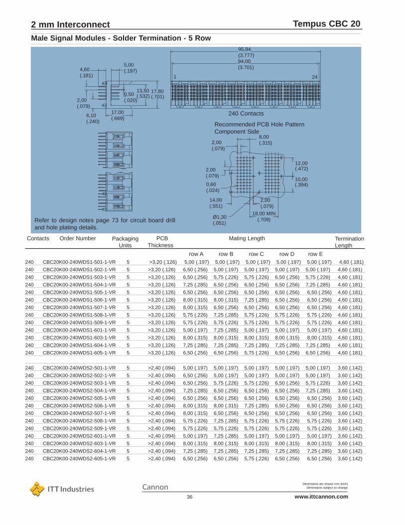
Tempus CBC 20
17,80(.701)
13,50(.532)0,50
(.020)
17,00(.669)
6,10(.240)
2,00(.079)
5,00(.197)4,60
(.181) 1
Recommended PCB Hole PatternComponent Side
240 Contacts
94,00(3.701)
95,94(3.777)
0,60(.024)
14,00(.551)
Ø1,30(.051)
18,00 MIN(.709)
2,00(.079)
2,00(.079)
10,00(.394)
12,00(.472)
8,00(.315)2,00
(.079)
24
Refer to design notes page 73 for circuit board drilland hole plating details.
240 CBC20K00-240WDS1-501-1-VR 5 >3,20 (.126) 5,00 (.197) 5,00 (.197) 5,00 (.197) 5,00 (.197) 5,00 (.197) 4,60 (.181)
240 CBC20K00-240WDS1-502-1-VR 5 >3,20 (.126) 6,50 (.256) 5,00 (.197) 5,00 (.197) 5,00 (.197) 5,00 (.197) 4,60 (.181)
240 CBC20K00-240WDS1-503-1-VR 5 >3,20 (.126) 6,50 (.256) 5,75 (.226) 5,75 (.226) 6,50 (.256) 5,75 (.226) 4,60 (.181)
240 CBC20K00-240WDS1-504-1-VR 5 >3,20 (.126) 7,25 (.285) 6,50 (.256) 6,50 (.256) 6,50 (.256) 7,25 (.285) 4,60 (.181)
240 CBC20K00-240WDS1-505-1-VR 5 >3,20 (.126) 6,50 (.256) 6,50 (.256) 6,50 (.256) 6,50 (.256) 6,50 (.256) 4,60 (.181)
240 CBC20K00-240WDS1-506-1-VR 5 >3,20 (.126) 8,00 (.315) 8,00 (.315) 7,25 (.285) 6,50 (.256) 6,50 (.256) 4,60 (.181)
240 CBC20K00-240WDS1-507-1-VR 5 >3,20 (.126) 8,00 (.315) 6,50 (.256) 6,50 (.256) 6,50 (.256) 6,50 (.256) 4,60 (.181)
240 CBC20K00-240WDS1-508-1-VR 5 >3,20 (.126) 5,75 (.226) 7,25 (.285) 5,75 (.226) 5,75 (.226) 5,75 (.226) 4,60 (.181)
240 CBC20K00-240WDS1-509-1-VR 5 >3,20 (.126) 5,75 (.226) 5,75 (.226) 5,75 (.226) 5,75 (.226) 5,75 (.226) 4,60 (.181)
240 CBC20K00-240WDS1-601-1-VR 5 >3,20 (.126) 5,00 (.197) 7,25 (.285) 5,00 (.197) 5,00 (.197) 5,00 (.197) 4,60 (.181)
240 CBC20K00-240WDS1-603-1-VR 5 >3,20 (.126) 8,00 (.315) 8,00 (.315) 8,00 (.315) 8,00 (.315) 8,00 (.315) 4,60 (.181)
240 CBC20K00-240WDS1-604-1-VR 5 >3,20 (.126) 7,25 (.285) 7,25 (.285) 7,25 (.285) 7,25 (.285) 7,25 (.285) 4,60 (.181)
240 CBC20K00-240WDS1-605-1-VR 5 >3,20 (.126) 6,50 (.256) 6,50 (.256) 5,75 (.226) 6,50 (.256) 6,50 (.256) 4,60 (.181)
240 CBC20K00-240WDS2-501-1-VR 5 >2,40 (.094) 5,00 (.197) 5,00 (.197) 5,00 (.197) 5,00 (.197) 5,00 (.197) 3,60 (.142)
240 CBC20K00-240WDS2-502-1-VR 5 >2,40 (.094) 6,50 (.256) 5,00 (.197) 5,00 (.197) 5,00 (.197) 5,00 (.197) 3,60 (.142)
240 CBC20K00-240WDS2-503-1-VR 5 >2,40 (.094) 6,50 (.256) 5,75 (.226) 5,75 (.226) 6,50 (.256) 5,75 (.226) 3,60 (.142)
240 CBC20K00-240WDS2-504-1-VR 5 >2,40 (.094) 7,25 (.285) 6,50 (.256) 6,50 (.256) 6,50 (.256) 7,25 (.285) 3,60 (.142)
240 CBC20K00-240WDS2-505-1-VR 5 >2,40 (.094) 6,50 (.256) 6,50 (.256) 6,50 (.256) 6,50 (.256) 6,50 (.256) 3,60 (.142)
240 CBC20K00-240WDS2-506-1-VR 5 >2,40 (.094) 8,00 (.315) 8,00 (.315) 7,25 (.285) 6,50 (.256) 6,50 (.256) 3,60 (.142)
240 CBC20K00-240WDS2-507-1-VR 5 >2,40 (.094) 8,00 (.315) 6,50 (.256) 6,50 (.256) 6,50 (.256) 6,50 (.256) 3,60 (.142)
240 CBC20K00-240WDS2-508-1-VR 5 >2,40 (.094) 5,75 (.226) 7,25 (.285) 5,75 (.226) 5,75 (.226) 5,75 (.226) 3,60 (.142)
240 CBC20K00-240WDS2-509-1-VR 5 >2,40 (.094) 5,75 (.226) 5,75 (.226) 5,75 (.226) 5,75 (.226) 5,75 (.226) 3,60 (.142)
240 CBC20K00-240WDS2-601-1-VR 5 >2,40 (.094) 5,00 (.197) 7,25 (.285) 5,00 (.197) 5,00 (.197) 5,00 (.197) 3,60 (.142)
240 CBC20K00-240WDS2-603-1-VR 5 >2,40 (.094) 8,00 (.315) 8,00 (.315) 8,00 (.315) 8,00 (.315) 8,00 (.315) 3,60 (.142)
240 CBC20K00-240WDS2-604-1-VR 5 >2,40 (.094) 7,25 (.285) 7,25 (.285) 7,25 (.285) 7,25 (.285) 7,25 (.285) 3,60 (.142)
240 CBC20K00-240WDS2-605-1-VR 5 >2,40 (.094) 6,50 (.256) 6,50 (.256) 5,75 (.226) 6,50 (.256) 6,50 (.256) 3,60 (.142)
Male Signal Modules - Solder Termination - 5 Row
2 mm Interconnect
Mating LengthPackagingUnits
PCBThickness
Termination Length
Contacts Order Number
row A row B row C row D row E

Dimensions are shown mm (inch)Dimensions subject to change
www.ittcannon.com37
Tempus CBC 20
1,50 A at 25°C; 1 A at 70°C
1000 Vrms
Initial: 5000MΩ; after climatic test: 1000 MΩ45 mΩ maximum
Current Rating
Withstanding Voltage
Insulation Resistance
Contact Resistance
Contact Pitch
Polarisation
Coding
Housing Material
Termination
Termination p.t.h. (solder)
Board Guiding Left to Right
Top to Bottom
Board Slot Pitch
Contact Material
Hertz Stress
Class 1
Plating
Insertion Force
Withdrawal Force
Technical DataMechanical Data
2,00 x 2,00 (.079 x .079)
By design
With coding key, see page 64
Liquid Crystal Polymer, UL94V-0 or PPS, UL94V-0
Eye of the needle compliant section, tin/lead plated
ø 0,70 (.028), refer to page 73
2,50 - 2,50 (.100 - .100)
1,50 - 1,50 (.060 - .060)
16,00 (.630) min.
Phosphor bronze
1200 MPa (174 klbf / sq. in.)
1000 cycles minimum
Palladium Nickel plus Gold over Nickel
0,45 N (1.6 oz) max. per contact
0,15 N (0,5 oz) min. per contact
Male Signal Modules - Press Fit Termination - 5 Row
• High temperature materials, not affected by reflow solder process
• High I/O, 25 contacts per linear centimetre (63 contacts per linear inch)
• Sequential mating provides live insertion capability
• High performance contacts, high hertz stress, 1000 cycles minimum
• Wide wall design for system tolerant2,50 (.098) out-of-centre board insertion
• Designed to conform with IEC61076-4-104, EIAis64, IEEE P896 Futurebus+, IEEE P1596 SCI and IEC 917metric modular order
• Stackable with other TEMPUS modules, with no loss of positions
Features
2 mm Interconnect
Electrical Data

Dimensions are shown mm (inch)Dimensions subject to change
www.ittcannon.com38
Tempus CBC 20
18,00 MIN(.709)
0,70(.028)
2,00(.079)
4,30(.169)
2,00(.079)
5,95(.234)
0,50(.020)
13,50(.532)
17,00(.669)
5,00(.197)
17,80(.701)
30 Contacts
Recommended PCB Hole PatternComponent Side
8,00(.315)
10,00(.394)
11,94(.470)
2,00(.079)
30 CBC20K00-030WDP1-501-1-VR 44 >1,80 (.071) 5,00 (.197) 5,00 (.197) 5,00 (.197) 5,00 (.197) 5,00 (.197) 4,30 (.169)
30 CBC20K00-030WDP1-502-1-VR 44 >1,80 (.071) 6,50 (.256) 5,00 (.197) 5,00 (.197) 5,00 (.197) 5,00 (.197) 4,30 (.169)
30 CBC20K00-030WDP1-503-1-VR 44 >1,80 (.071) 6,50 (.256) 5,75 (.226) 5,75 (.226) 6,50 (.256) 5,75 (.226) 4,30 (.169)
30 CBC20K00-030WDP1-504-1-VR 44 >1,80 (.071) 7,25 (.285) 6,50 (.256) 6,50 (.256) 6,50 (.256) 7,25 (.285) 4,30 (.169)
30 CBC20K00-030WDP1-505-1-VR 44 >1,80 (.071) 6,50 (.256) 6,50 (.256) 6,50 (.256) 6,50 (.256) 6,50 (.256) 4,30 (.169)
30 CBC20K00-030WDP1-506-1-VR 44 >1,80 (.071) 8,00 (.315) 8,00 (.315) 7,25 (.285) 6,50 (.256) 6,50 (.256) 4,30 (.169)
30 CBC20K00-030WDP1-507-1-VR 44 >1,80 (.071) 8,00 (.315) 6,50 (.256) 6,50 (.256) 6,50 (.256) 6,50 (.256) 4,30 (.169)
30 CBC20K00-030WDP1-508-1-VR 44 >1,80 (.071) 5,75 (.226) 7,25 (.285) 5,75 (.226) 5,75 (.226) 5,75 (.226) 4,30 (.169)
30 CBC20K00-030WDP1-509-1-VR 44 >1,80 (.071) 5,75 (.226) 5,75 (.226) 5,75 (.226) 5,75 (.226) 5,75 (.226) 4,30 (.169)
30 CBC20K00-030WDP1-601-1-VR 44 >1,80 (.071) 5,00 (.197) 7,25 (.285) 5,00 (.197) 5,00 (.197) 5,00 (.197) 4,30 (.169)
30 CBC20K00-030WDP1-603-1-VR 44 >1,80 (.071) 8,00 (.315) 8,00 (.315) 8,00 (.315) 8,00 (.315) 8,00 (.315) 4,30 (.169)
30 CBC20K00-030WDP1-604-1-VR 44 >1,80 (.071) 7,25 (.285) 7,25 (.285) 7,25 (.285) 7,25 (.285) 7,25 (.285) 4,30 (.169)
30 CBC20K00-030WDP1-605-1-VR 44 >1,80 (.071) 6,50 (.256) 6,50 (.256) 5,75 (.226) 6,50 (.256) 6,50 (.256) 4,30 (.169)
30 CBC20K00-030WDP3-501-1-VR 44 >1,80 (.071) 5,00 (.197) 5,00 (.197) 5,00 (.197) 5,00 (.197) 5,00 (.197) 4,30 (.169)
30 CBC20K00-030WDP3-502-1-VR 44 >1,80 (.071) 6,50 (.256) 5,00 (.197) 5,00 (.197) 5,00 (.197) 5,00 (.197) 4,30 (.169)
30 CBC20K00-030WDP3-503-1-VR 44 >1,80 (.071) 6,50 (.256) 5,75 (.226) 5,75 (.226) 6,50 (.256) 5,75 (.226) 4,30 (.169)
30 CBC20K00-030WDP3-504-1-VR 44 >1,80 (.071) 7,25 (.285) 6,50 (.256) 6,50 (.256) 6,50 (.256) 7,25 (.285) 4,30 (.169)
30 CBC20K00-030WDP3-505-1-VR 44 >1,80 (.071) 6,50 (.256) 6,50 (.256) 6,50 (.256) 6,50 (.256) 6,50 (.256) 4,30 (.169)
30 CBC20K00-030WDP3-506-1-VR 44 >1,80 (.071) 8,00 (.315) 8,00 (.315) 7,25 (.285) 6,50 (.256) 6,50 (.256) 4,30 (.169)
30 CBC20K00-030WDP3-507-1-VR 44 >1,80 (.071) 8,00 (.315) 6,50 (.256) 6,50 (.256) 6,50 (.256) 6,50 (.256) 4,30 (.169)
30 CBC20K00-030WDP3-508-1-VR 44 >1,80 (.071) 5,75 (.226) 7,25 (.285) 5,75 (.226) 5,75 (.226) 5,75 (.226) 4,30 (.169)
30 CBC20K00-030WDP3-509-1-VR 44 >1,80 (.071) 5,75 (.226) 5,75 (.226) 5,75 (.226) 5,75 (.226) 5,75 (.226) 4,30 (.169)
30 CBC20K00-030WDP3-601-1-VR 44 >1,80 (.071) 5,00 (.197) 7,25 (.285) 5,00 (.197) 5,00 (.197) 5,00 (.197) 4,30 (.169)
30 CBC20K00-030WDP3-603-1-VR 44 >1,80 (.071) 8,00 (.315) 8,00 (.315) 8,00 (.315) 8,00 (.315) 8,00 (.315) 4,30 (.169)
30 CBC20K00-030WDP3-604-1-VR 44 >1,80 (.071) 7,25 (.285) 7,25 (.285) 7,25 (.285) 7,25 (.285) 7,25 (.285) 4,30 (.169)
30 CBC20K00-030WDP3-605-1-VR 44 >1,80 (.071) 6,50 (.256) 6,50 (.256) 5,75 (.226) 6,50 (.256) 6,50 (.256) 4,30 (.169)
Refer to design notes page 73 for circuit board drill and hole plating details.
Male Signal Modules - Press Fit Termination - 5 Row
2 mm Interconnect
Mating LengthPackagingUnits
PCBThickness
Termination Length
Contacts Order Number
row A row B row C row D row E

Dimensions are shown mm (inch)Dimensions subject to change
www.ittcannon.com39
Tempus CBC 20
30 CBC20K00-030WDU1-501-1-VR 44 >1,80 (.071) 5,00 (.197) 5,00 (.197) 5,00 (.197) 5,00 (.197) 5,00 (.197) 4,30 (.169)
30 CBC20K00-030WDU1-502-1-VR 44 >1,80 (.071) 6,50 (.256) 5,00 (.197) 5,00 (.197) 5,00 (.197) 5,00 (.197) 4,30 (.169)
30 CBC20K00-030WDU1-503-1-VR 44 >1,80 (.071) 6,50 (.256) 5,75 (.226) 5,75 (.226) 6,50 (.256) 5,75 (.226) 4,30 (.169)
30 CBC20K00-030WDU1-504-1-VR 44 >1,80 (.071) 7,25 (.285) 6,50 (.256) 6,50 (.256) 6,50 (.256) 7,25 (.285) 4,30 (.169)
30 CBC20K00-030WDU1-505-1-VR 44 >1,80 (.071) 6,50 (.256) 6,50 (.256) 6,50 (.256) 6,50 (.256) 6,50 (.256) 4,30 (.169)
30 CBC20K00-030WDU1-506-1-VR 44 >1,80 (.071) 8,00 (.315) 8,00 (.315) 7,25 (.285) 6,50 (.256) 6,50 (.256) 4,30 (.169)
30 CBC20K00-030WDU1-507-1-VR 44 >1,80 (.071) 8,00 (.315) 6,50 (.256) 6,50 (.256) 6,50 (.256) 6,50 (.256) 4,30 (.169)
30 CBC20K00-030WDU1-508-1-VR 44 >1,80 (.071) 5,75 (.226) 7,25 (.285) 5,75 (.226) 5,75 (.226) 5,75 (.226) 4,30 (.169)
30 CBC20K00-030WDU1-509-1-VR 44 >1,80 (.071) 5,75 (.226) 5,75 (.226) 5,75 (.226) 5,75 (.226) 5,75 (.226) 4,30 (.169)
30 CBC20K00-030WDU1-601-1-VR 44 >1,80 (.071) 5,00 (.197) 7,25 (.285) 5,00 (.197) 5,00 (.197) 5,00 (.197) 4,30 (.169)
30 CBC20K00-030WDU1-603-1-VR 44 >1,80 (.071) 8,00 (.315) 8,00 (.315) 8,00 (.315) 8,00 (.315) 8,00 (.315) 4,30 (.169)
30 CBC20K00-030WDU1-604-1-VR 44 >1,80 (.071) 7,25 (.285) 7,25 (.285) 7,25 (.285) 7,25 (.285) 7,25 (.285) 4,30 (.169)
30 CBC20K00-030WDU1-605-1-VR 44 >1,80 (.071) 6,50 (.256) 6,50 (.256) 5,75 (.226) 6,50 (.256) 6,50 (.256) 4,30 (.169)
30 CBC20K00-030WDV2-501-1-VR 44 >1,80 (.071) 5,00 (.197) 5,00 (.197) 5,00 (.197) 5,00 (.197) 5,00 (.197) 17,00 (.669)
30 CBC20K00-030WDV2-502-1-VR 44 >1,80 (.071) 6,50 (.256) 5,00 (.197) 5,00 (.197) 5,00 (.197) 5,00 (.197) 17,00 (.669)
30 CBC20K00-030WDV2-503-1-VR 44 >1,80 (.071) 6,50 (.256) 5,75 (.226) 5,75 (.226) 6,50 (.256) 5,75 (.226) 17,00 (.669)
30 CBC20K00-030WDV2-504-1-VR 44 >1,80 (.071) 7,25 (.285) 6,50 (.256) 6,50 (.256) 6,50 (.256) 7,25 (.285) 17,00 (.669)
30 CBC20K00-030WDV2-505-1-VR 44 >1,80 (.071) 6,50 (.256) 6,50 (.256) 6,50 (.256) 6,50 (.256) 6,50 (.256) 17,00 (.669)
30 CBC20K00-030WDV2-506-1-VR 44 >1,80 (.071) 8,00 (.315) 8,00 (.315) 7,25 (.285) 6,50 (.256) 6,50 (.256) 17,00 (.669)
30 CBC20K00-030WDV2-507-1-VR 44 >1,80 (.071) 8,00 (.315) 6,50 (.256) 6,50 (.256) 6,50 (.256) 6,50 (.256) 17,00 (.669)
30 CBC20K00-030WDV2-508-1-VR 44 >1,80 (.071) 5,75 (.226) 7,25 (.285) 5,75 (.226) 5,75 (.226) 5,75 (.226) 17,00 (.669)
30 CBC20K00-030WDV2-509-1-VR 44 >1,80 (.071) 5,75 (.226) 5,75 (.226) 5,75 (.226) 5,75 (.226) 5,75 (.226) 17,00 (.669)
30 CBC20K00-030WDV2-601-1-VR 44 >1,80 (.071) 5,00 (.197) 7,25 (.285) 5,00 (.197) 5,00 (.197) 5,00 (.197) 17,00 (.669)
30 CBC20K00-030WDV2-603-1-VR 44 >1,80 (.071) 8,00 (.315) 8,00 (.315) 8,00 (.315) 8,00 (.315) 8,00 (.315) 17,00 (.669)
30 CBC20K00-030WDV2-604-1-VR 44 >1,80 (.071) 7,25 (.285) 7,25 (.285) 7,25 (.285) 7,25 (.285) 7,25 (.285) 17,00 (.669)
30 CBC20K00-030WDV2-605-1-VR 44 >1,80 (.071) 6,50 (.256) 6,50 (.256) 5,75 (.226) 6,50 (.256) 6,50 (.256) 17,00 (.669)
Male Signal Modules - Press Fit Termination - 5 Row
2 mm Interconnect
Mating LengthPackagingUnits
PCBThickness
Termination Length
Contacts Order Number
row A row B row C row D row E

Dimensions are shown mm (inch)Dimensions subject to change
www.ittcannon.com40
Tempus CBC 20
18,00 MIN(.709)
0,70(.028)
2,00(.079)
Recommended PCB Hole PatternComponent Side
8,00(.315)
2,00(.079)
60 Contacts
121
4,30(.169)
2,00(.079)
5,95(.234)
0,50(.020)
13,50(.532)
17,00(.669)
5,00(.197)
17,80(.701)
Refer to design notes page 73 for circuit board drill and hole plating details.
60 CBC20K00-060WDP1-501-1-VR 22 >1,80 (.071) 5,00 (.197) 5,00 (.197) 5,00 (.197) 5,00 (.197) 5,00 (.197) 4,30 (.169)
60 CBC20K00-060WDP1-502-1-VR 22 >1,80 (.071) 6,50 (.256) 5,00 (.197) 5,00 (.197) 5,00 (.197) 5,00 (.197) 4,30 (.169)
60 CBC20K00-060WDP1-503-1-VR 22 >1,80 (.071) 6,50 (.256) 5,75 (.226) 5,75 (.226) 6,50 (.256) 5,75 (.226) 4,30 (.169)
60 CBC20K00-060WDP1-504-1-VR 22 >1,80 (.071) 7,25 (.285) 6,50 (.256) 6,50 (.256) 6,50 (.256) 7,25 (.285) 4,30 (.169)
60 CBC20K00-060WDP1-505-1-VR 22 >1,80 (.071) 6,50 (.256) 6,50 (.256) 6,50 (.256) 6,50 (.256) 6,50 (.256) 4,30 (.169)
60 CBC20K00-060WDP1-506-1-VR 22 >1,80 (.071) 8,00 (.315) 8,00 (.315) 7,25 (.285) 6,50 (.256) 6,50 (.256) 4,30 (.169)
60 CBC20K00-060WDP1-507-1-VR 22 >1,80 (.071) 8,00 (.315) 6,50 (.256) 6,50 (.256) 6,50 (.256) 6,50 (.256) 4,30 (.169)
60 CBC20K00-060WDP1-508-1-VR 22 >1,80 (.071) 5,75 (.226) 7,25 (.285) 5,75 (.226) 5,75 (.226) 5,75 (.226) 4,30 (.169)
60 CBC20K00-060WDP1-509-1-VR 22 >1,80 (.071) 5,75 (.226) 5,75 (.226) 5,75 (.226) 5,75 (.226) 5,75 (.226) 4,30 (.169)
60 CBC20K00-060WDP1-601-1-VR 22 >1,80 (.071) 5,00 (.197) 7,25 (.285) 5,00 (.197) 5,00 (.197) 5,00 (.197) 4,30 (.169)
60 CBC20K00-060WDP1-603-1-VR 22 >1,80 (.071) 8,00 (.315) 8,00 (.315) 8,00 (.315) 8,00 (.315) 8,00 (.315) 4,30 (.169)
60 CBC20K00-060WDP1-604-1-VR 22 >1,80 (.071) 7,25 (.285) 7,25 (.285) 7,25 (.285) 7,25 (.285) 7,25 (.285) 4,30 (.169)
60 CBC20K00-060WDP1-605-1-VR 22 >1,80 (.071) 6,50 (.256) 6,50 (.256) 5,75 (.226) 6,50 (.256) 6,50 (.256) 4,30 (.169)
Male Signal Modules - Press Fit Termination - 5 Row
2 mm Interconnect
Mating LengthPackagingUnits
PCBThickness
Termination Length
Contacts Order Number
row A row B row C row D row E

Dimensions are shown mm (inch)Dimensions subject to change
www.ittcannon.com41
Tempus CBC 20
60 CBC20K00-060WDP3-501-1-VR 22 >1,80 (.071) 5,00 (.197) 5,00 (.197) 5,00 (.197) 5,00 (.197) 5,00 (.197) 4,30 (.169)
60 CBC20K00-060WDP3-502-1-VR 22 >1,80 (.071) 6,50 (.256) 5,00 (.197) 5,00 (.197) 5,00 (.197) 5,00 (.197) 4,30 (.169)
60 CBC20K00-060WDP3-503-1-VR 22 >1,80 (.071) 6,50 (.256) 5,75 (.226) 5,75 (.226) 6,50 (.256) 5,75 (.226) 4,30 (.169)
60 CBC20K00-060WDP3-504-1-VR 22 >1,80 (.071) 7,25 (.285) 6,50 (.256) 6,50 (.256) 6,50 (.256) 7,25 (.285) 4,30 (.169)
60 CBC20K00-060WDP3-505-1-VR 22 >1,80 (.071) 6,50 (.256) 6,50 (.256) 6,50 (.256) 6,50 (.256) 6,50 (.256) 4,30 (.169)
60 CBC20K00-060WDP3-506-1-VR 22 >1,80 (.071) 8,00 (.315) 8,00 (.315) 7,25 (.285) 6,50 (.256) 6,50 (.256) 4,30 (.169)
60 CBC20K00-060WDP3-507-1-VR 22 >1,80 (.071) 8,00 (.315) 6,50 (.256) 6,50 (.256) 6,50 (.256) 6,50 (.256) 4,30 (.169)
60 CBC20K00-060WDP3-508-1-VR 22 >1,80 (.071) 5,75 (.226) 7,25 (.285) 5,75 (.226) 5,75 (.226) 5,75 (.226) 4,30 (.169)
60 CBC20K00-060WDP3-509-1-VR 22 >1,80 (.071) 5,75 (.226) 5,75 (.226) 5,75 (.226) 5,75 (.226) 5,75 (.226) 4,30 (.169)
60 CBC20K00-060WDP3-601-1-VR 22 >1,80 (.071) 5,00 (.197) 7,25 (.285) 5,00 (.197) 5,00 (.197) 5,00 (.197) 4,30 (.169)
60 CBC20K00-060WDP3-603-1-VR 22 >1,80 (.071) 8,00 (.315) 8,00 (.315) 8,00 (.315) 8,00 (.315) 8,00 (.315) 4,30 (.169)
60 CBC20K00-060WDP3-604-1-VR 22 >1,80 (.071) 7,25 (.285) 7,25 (.285) 7,25 (.285) 7,25 (.285) 7,25 (.285) 4,30 (.169)
60 CBC20K00-060WDP3-605-1-VR 22 >1,80 (.071) 6,50 (.256) 6,50 (.256) 5,75 (.226) 6,50 (.256) 6,50 (.256) 4,30 (.169)
60 CBC20K00-060WDU1-501-1-VR 22 >1,80 (.071) 5,00 (.197) 5,00 (.197) 5,00 (.197) 5,00 (.197) 5,00 (.197) 13,60 (.535)
60 CBC20K00-060WDU1-502-1-VR 22 >1,80 (.071) 6,50 (.256) 5,00 (.197) 5,00 (.197) 5,00 (.197) 5,00 (.197) 13,60 (.535)
60 CBC20K00-060WDU1-503-1-VR 22 >1,80 (.071) 6,50 (.256) 5,75 (.226) 5,75 (.226) 6,50 (.256) 5,75 (.226) 13,60 (.535)
60 CBC20K00-060WDU1-504-1-VR 22 >1,80 (.071) 7,25 (.285) 6,50 (.256) 6,50 (.256) 6,50 (.256) 7,25 (.285) 13,60 (.535)
60 CBC20K00-060WDU1-505-1-VR 22 >1,80 (.071) 6,50 (.256) 6,50 (.256) 6,50 (.256) 6,50 (.256) 6,50 (.256) 13,60 (.535)
60 CBC20K00-060WDU1-506-1-VR 22 >1,80 (.071) 8,00 (.315) 8,00 (.315) 7,25 (.285) 6,50 (.256) 6,50 (.256) 13,60 (.535)
60 CBC20K00-060WDU1-507-1-VR 22 >1,80 (.071) 8,00 (.315) 6,50 (.256) 6,50 (.256) 6,50 (.256) 6,50 (.256) 13,60 (.535)
60 CBC20K00-060WDU1-508-1-VR 22 >1,80 (.071) 5,75 (.226) 7,25 (.285) 5,75 (.226) 5,75 (.226) 5,75 (.226) 13,60 (.535)
60 CBC20K00-060WDU1-509-1-VR 22 >1,80 (.071) 5,75 (.226) 5,75 (.226) 5,75 (.226) 5,75 (.226) 5,75 (.226) 13,60 (.535)
60 CBC20K00-060WDU1-601-1-VR 22 >1,80 (.071) 5,00 (.197) 7,25 (.285) 5,00 (.197) 5,00 (.197) 5,00 (.197) 13,60 (.535)
60 CBC20K00-060WDU1-603-1-VR 22 >1,80 (.071) 8,00 (.315) 8,00 (.315) 8,00 (.315) 8,00 (.315) 8,00 (.315) 13,60 (.535)
60 CBC20K00-060WDU1-604-1-VR 22 >1,80 (.071) 7,25 (.285) 7,25 (.285) 7,25 (.285) 7,25 (.285) 7,25 (.285) 13,60 (.535)
60 CBC20K00-060WDU1-605-1-VR 22 >1,80 (.071) 6,50 (.256) 6,50 (.256) 5,75 (.226) 6,50 (.256) 6,50 (.256) 13,60 (.535)
60 CBC20K00-060WDV2-501-1-VR 22 >1,80 (.071) 5,00 (.197) 5,00 (.197) 5,00 (.197) 5,00 (.197) 5,00 (.197) 17,00 (.669)
60 CBC20K00-060WDV2-502-1-VR 22 >1,80 (.071) 6,50 (.256) 5,00 (.197) 5,00 (.197) 5,00 (.197) 5,00 (.197) 17,00 (.669)
60 CBC20K00-060WDV2-503-1-VR 22 >1,80 (.071) 6,50 (.256) 5,75 (.226) 5,75 (.226) 6,50 (.256) 5,75 (.226) 17,00 (.669)
60 CBC20K00-060WDV2-504-1-VR 22 >1,80 (.071) 7,25 (.285) 6,50 (.256) 6,50 (.256) 6,50 (.256) 7,25 (.285) 17,00 (.669)
60 CBC20K00-060WDV2-505-1-VR 22 >1,80 (.071) 6,50 (.256) 6,50 (.256) 6,50 (.256) 6,50 (.256) 6,50 (.256) 17,00 (.669)
60 CBC20K00-060WDV2-506-1-VR 22 >1,80 (.071) 8,00 (.315) 8,00 (.315) 7,25 (.285) 6,50 (.256) 6,50 (.256) 17,00 (.669)
60 CBC20K00-060WDV2-507-1-VR 22 >1,80 (.071) 8,00 (.315) 6,50 (.256) 6,50 (.256) 6,50 (.256) 6,50 (.256) 17,00 (.669)
60 CBC20K00-060WDV2-508-1-VR 22 >1,80 (.071) 5,75 (.226) 7,25 (.285) 5,75 (.226) 5,75 (.226) 5,75 (.226) 17,00 (.669)
60 CBC20K00-060WDV2-509-1-VR 22 >1,80 (.071) 5,75 (.226) 5,75 (.226) 5,75 (.226) 5,75 (.226) 5,75 (.226) 17,00 (.669)
60 CBC20K00-060WDV2-601-1-VR 22 >1,80 (.071) 5,00 (.197) 7,25 (.285) 5,00 (.197) 5,00 (.197) 5,00 (.197) 17,00 (.669)
60 CBC20K00-060WDV2-603-1-VR 22 >1,80 (.071) 8,00 (.315) 8,00 (.315) 8,00 (.315) 8,00 (.315) 8,00 (.315) 17,00 (.669)
60 CBC20K00-060WDV2-604-1-VR 22 >1,80 (.071) 7,25 (.285) 7,25 (.285) 7,25 (.285) 7,25 (.285) 7,25 (.285) 17,00 (.669)
60 CBC20K00-060WDV2-605-1-VR 22 >1,80 (.071) 6,50 (.256) 6,50 (.256) 5,75 (.226) 6,50 (.256) 6,50 (.256) 17,00 (.669)
Male Signal Modules - Press Fit Termination - 5 Row
2 mm Interconnect
Mating LengthPackagingUnits
PCBThickness
Termination Length
Contacts Order Number
row A row B row C row D row E

Dimensions are shown mm (inch)Dimensions subject to change
www.ittcannon.com42
Tempus CBC 20
18,00 MIN(.709)
0,70(.028)
2,00(.079)
Recommended PCB Hole PatternComponent Side
8,00(.315)
2,00(.079)
120 Contacts
241
4,30(.169)
2,00(.079)
5,95(.234)
0,50(.020)
13,50(.532)
17,00(.669)
5,00(.197)
17,80(.701)
120 CBC20K00-120WDP1-501-1-VR 11 >1,80 (.071) 5,00 (.197) 5,00 (.197) 5,00 (.197) 5,00 (.197) 5,00 (.197) 4,30 (.169)
120 CBC20K00-120WDP1-502-1-VR 11 >1,80 (.071) 6,50 (.256) 5,00 (.197) 5,00 (.197) 5,00 (.197) 5,00 (.197) 4,30 (.169)
120 CBC20K00-120WDP1-503-1-VR 11 >1,80 (.071) 6,50 (.256) 5,75 (.226) 5,75 (.226) 6,50 (.256) 5,75 (.226) 4,30 (.169)
120 CBC20K00-120WDP1-504-1-VR 11 >1,80 (.071) 7,25 (.285) 6,50 (.256) 6,50 (.256) 6,50 (.256) 7,25 (.285) 4,30 (.169)
120 CBC20K00-120WDP1-505-1-VR 11 >1,80 (.071) 6,50 (.256) 6,50 (.256) 6,50 (.256) 6,50 (.256) 6,50 (.256) 4,30 (.169)
120 CBC20K00-120WDP1-506-1-VR 11 >1,80 (.071) 8,00 (.315) 8,00 (.315) 7,25 (.285) 6,50 (.256) 6,50 (.256) 4,30 (.169)
120 CBC20K00-120WDP1-507-1-VR 11 >1,80 (.071) 8,00 (.315) 6,50 (.256) 6,50 (.256) 6,50 (.256) 6,50 (.256) 4,30 (.169)
120 CBC20K00-120WDP1-508-1-VR 11 >1,80 (.071) 5,75 (.226) 7,25 (.285) 5,75 (.226) 5,75 (.226) 5,75 (.226) 4,30 (.169)
120 CBC20K00-120WDP1-509-1-VR 11 >1,80 (.071) 5,75 (.226) 5,75 (.226) 5,75 (.226) 5,75 (.226) 5,75 (.226) 4,30 (.169)
120 CBC20K00-120WDP1-601-1-VR 11 >1,80 (.071) 5,00 (.197) 7,25 (.285) 5,00 (.197) 5,00 (.197) 5,00 (.197) 4,30 (.169)
120 CBC20K00-120WDP1-603-1-VR 11 >1,80 (.071) 8,00 (.315) 8,00 (.315) 8,00 (.315) 8,00 (.315) 8,00 (.315) 4,30 (.169)
120 CBC20K00-120WDP1-604-1-VR 11 >1,80 (.071) 7,25 (.285) 7,25 (.285) 7,25 (.285) 7,25 (.285) 7,25 (.285) 4,30 (.169)
120 CBC20K00-120WDP1-605-1-VR 11 >1,80 (.071) 6,50 (.256) 6,50 (.256) 5,75 (.226) 6,50 (.256) 6,50 (.256) 4,30 (.169)
Refer to design notes page 73 for circuit board drill and hole plating details.
Male Signal Modules - Press Fit Termination - 5 Row
2 mm Interconnect
Mating LengthPackagingUnits
PCBThickness
Termination Length
Contacts Order Number
row A row B row C row D row E

Dimensions are shown mm (inch)Dimensions subject to change
www.ittcannon.com43
Tempus CBC 20
120 CBC20K00-120WDP3-501-1-VR 11 >1,80 (.071) 5,00 (.197) 5,00 (.197) 5,00 (.197) 5,00 (.197) 5,00 (.197) 4,30 (.169)
120 CBC20K00-120WDP3-502-1-VR 11 >1,80 (.071) 6,50 (.256) 5,00 (.197) 5,00 (.197) 5,00 (.197) 5,00 (.197) 4,30 (.169)
120 CBC20K00-120WDP3-503-1-VR 11 >1,80 (.071) 6,50 (.256) 5,75 (.226) 5,75 (.226) 6,50 (.256) 5,75 (.226) 4,30 (.169)
120 CBC20K00-120WDP3-504-1-VR 11 >1,80 (.071) 7,25 (.285) 6,50 (.256) 6,50 (.256) 6,50 (.256) 7,25 (.285) 4,30 (.169)
120 CBC20K00-120WDP3-505-1-VR 11 >1,80 (.071) 6,50 (.256) 6,50 (.256) 6,50 (.256) 6,50 (.256) 6,50 (.256) 4,30 (.169)
120 CBC20K00-120WDP3-506-1-VR 11 >1,80 (.071) 8,00 (.315) 8,00 (.315) 7,25 (.285) 6,50 (.256) 6,50 (.256) 4,30 (.169)
120 CBC20K00-120WDP3-507-1-VR 11 >1,80 (.071) 8,00 (.315) 6,50 (.256) 6,50 (.256) 6,50 (.256) 6,50 (.256) 4,30 (.169)
120 CBC20K00-120WDP3-508-1-VR 11 >1,80 (.071) 5,75 (.226) 7,25 (.285) 5,75 (.226) 5,75 (.226) 5,75 (.226) 4,30 (.169)
120 CBC20K00-120WDP3-509-1-VR 11 >1,80 (.071) 5,75 (.226) 5,75 (.226) 5,75 (.226) 5,75 (.226) 5,75 (.226) 4,30 (.169)
120 CBC20K00-120WDP3-601-1-VR 11 >1,80 (.071) 5,00 (.197) 7,25 (.285) 5,00 (.197) 5,00 (.197) 5,00 (.197) 4,30 (.169)
120 CBC20K00-120WDP3-603-1-VR 11 >1,80 (.071) 8,00 (.315) 8,00 (.315) 8,00 (.315) 8,00 (.315) 8,00 (.315) 4,30 (.169)
120 CBC20K00-120WDP3-604-1-VR 11 >1,80 (.071) 7,25 (.285) 7,25 (.285) 7,25 (.285) 7,25 (.285) 7,25 (.285) 4,30 (.169)
120 CBC20K00-120WDP3-605-1-VR 11 >1,80 (.071) 6,50 (.256) 6,50 (.256) 5,75 (.226) 6,50 (.256) 6,50 (.256) 4,30 (.169)
120 CBC20K00-120WDU1-501-1-VR 11 >1,80 (.071) 5,00 (.197) 5,00 (.197) 5,00 (.197) 5,00 (.197) 5,00 (.197) 13,60 (.535)
120 CBC20K00-120WDU1-502-1-VR 11 >1,80 (.071) 6,50 (.256) 5,00 (.197) 5,00 (.197) 5,00 (.197) 5,00 (.197) 13,60 (.535)
120 CBC20K00-120WDU1-503-1-VR 11 >1,80 (.071) 6,50 (.256) 5,75 (.226) 5,75 (.226) 6,50 (.256) 5,75 (.226) 13,60 (.535)
120 CBC20K00-120WDU1-504-1-VR 11 >1,80 (.071) 7,25 (.285) 6,50 (.256) 6,50 (.256) 6,50 (.256) 7,25 (.285) 13,60 (.535)
120 CBC20K00-120WDU1-505-1-VR 11 >1,80 (.071) 6,50 (.256) 6,50 (.256) 6,50 (.256) 6,50 (.256) 6,50 (.256) 13,60 (.535)
120 CBC20K00-120WDU1-506-1-VR 11 >1,80 (.071) 8,00 (.315) 8,00 (.315) 7,25 (.285) 6,50 (.256) 6,50 (.256) 13,60 (.535)
120 CBC20K00-120WDU1-507-1-VR 11 >1,80 (.071) 8,00 (.315) 6,50 (.256) 6,50 (.256) 6,50 (.256) 6,50 (.256) 13,60 (.535)
120 CBC20K00-120WDU1-508-1-VR 11 >1,80 (.071) 5,75 (.226) 7,25 (.285) 5,75 (.226) 5,75 (.226) 5,75 (.226) 13,60 (.535)
120 CBC20K00-120WDU1-509-1-VR 11 >1,80 (.071) 5,75 (.226) 5,75 (.226) 5,75 (.226) 5,75 (.226) 5,75 (.226) 13,60 (.535)
120 CBC20K00-120WDU1-601-1-VR 11 >1,80 (.071) 5,00 (.197) 7,25 (.285) 5,00 (.197) 5,00 (.197) 5,00 (.197) 13,60 (.535)
120 CBC20K00-120WDU1-603-1-VR 11 >1,80 (.071) 8,00 (.315) 8,00 (.315) 8,00 (.315) 8,00 (.315) 8,00 (.315) 13,60 (.535)
120 CBC20K00-120WDU1-604-1-VR 11 >1,80 (.071) 7,25 (.285) 7,25 (.285) 7,25 (.285) 7,25 (.285) 7,25 (.285) 13,60 (.535)
120 CBC20K00-120WDU1-605-1-VR 11 >1,80 (.071) 6,50 (.256) 6,50 (.256) 5,75 (.226) 6,50 (.256) 6,50 (.256) 13,60 (.535)
120 CBC20K00-120WDV2-501-1-VR 11 >1,80 (.071) 5,00 (.197) 5,00 (.197) 5,00 (.197) 5,00 (.197) 5,00 (.197) 17,00 (.669)
120 CBC20K00-120WDV2-502-1-VR 11 >1,80 (.071) 6,50 (.256) 5,00 (.197) 5,00 (.197) 5,00 (.197) 5,00 (.197) 17,00 (.669)
120 CBC20K00-120WDV2-503-1-VR 11 >1,80 (.071) 6,50 (.256) 5,75 (.226) 5,75 (.226) 6,50 (.256) 5,75 (.226) 17,00 (.669)
120 CBC20K00-120WDV2-504-1-VR 11 >1,80 (.071) 7,25 (.285) 6,50 (.256) 6,50 (.256) 6,50 (.256) 7,25 (.285) 17,00 (.669)
120 CBC20K00-120WDV2-505-1-VR 11 >1,80 (.071) 6,50 (.256) 6,50 (.256) 6,50 (.256) 6,50 (.256) 6,50 (.256) 17,00 (.669)
120 CBC20K00-120WDV2-506-1-VR 11 >1,80 (.071) 8,00 (.315) 8,00 (.315) 7,25 (.285) 6,50 (.256) 6,50 (.256) 17,00 (.669)
120 CBC20K00-120WDV2-507-1-VR 11 >1,80 (.071) 8,00 (.315) 6,50 (.256) 6,50 (.256) 6,50 (.256) 6,50 (.256) 17,00 (.669)
120 CBC20K00-120WDV2-508-1-VR 11 >1,80 (.071) 5,75 (.226) 7,25 (.285) 5,75 (.226) 5,75 (.226) 5,75 (.226) 17,00 (.669)
120 CBC20K00-120WDV2-509-1-VR 11 >1,80 (.071) 5,75 (.226) 5,75 (.226) 5,75 (.226) 5,75 (.226) 5,75 (.226) 17,00 (.669)
120 CBC20K00-120WDV2-601-1-VR 11 >1,80 (.071) 5,00 (.197) 7,25 (.285) 5,00 (.197) 5,00 (.197) 5,00 (.197) 17,00 (.669)
120 CBC20K00-120WDV2-603-1-VR 11 >1,80 (.071) 8,00 (.315) 8,00 (.315) 8,00 (.315) 8,00 (.315) 8,00 (.315) 17,00 (.669)
120 CBC20K00-120WDV2-604-1-VR 11 >1,80 (.071) 7,25 (.285) 7,25 (.285) 7,25 (.285) 7,25 (.285) 7,25 (.285) 17,00 (.669)
120 CBC20K00-120WDV2-605-1-VR 11 >1,80 (.071) 6,50 (.256) 6,50 (.256) 5,75 (.226) 6,50 (.256) 6,50 (.256) 17,00 (.669)
Male Signal Modules - Press Fit Termination - 5 Row
2 mm Interconnect
Mating LengthPackagingUnits
PCBThickness
Termination Length
Contacts Order Number
row A row B row C row D row E
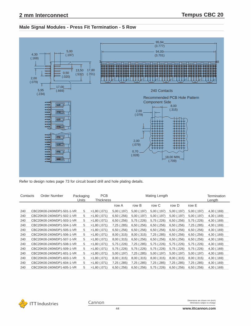
Dimensions are shown mm (inch)Dimensions subject to change
www.ittcannon.com44
Tempus CBC 20
94,00(3.701)
95,94(3.777)
18,00 MIN(.709)
0,70(.028)
2,00(.079)
Recommended PCB Hole PatternComponent Side
8,00(.315)2,00
(.079)
240 Contacts
481
4,30(.169)
2,00(.079)
5,95(.234)
0,50(.020)
13,50(.532)
17,00(.669)
5,00(.197)
17,80(.701)
240 CBC20K00-240WDP1-501-1-VR 5 >1,80 (.071) 5,00 (.197) 5,00 (.197) 5,00 (.197) 5,00 (.197) 5,00 (.197) 4,30 (.169)
240 CBC20K00-240WDP1-502-1-VR 5 >1,80 (.071) 6,50 (.256) 5,00 (.197) 5,00 (.197) 5,00 (.197) 5,00 (.197) 4,30 (.169)
240 CBC20K00-240WDP1-503-1-VR 5 >1,80 (.071) 6,50 (.256) 5,75 (.226) 5,75 (.226) 6,50 (.256) 5,75 (.226) 4,30 (.169)
240 CBC20K00-240WDP1-504-1-VR 5 >1,80 (.071) 7,25 (.285) 6,50 (.256) 6,50 (.256) 6,50 (.256) 7,25 (.285) 4,30 (.169)
240 CBC20K00-240WDP1-505-1-VR 5 >1,80 (.071) 6,50 (.256) 6,50 (.256) 6,50 (.256) 6,50 (.256) 6,50 (.256) 4,30 (.169)
240 CBC20K00-240WDP1-506-1-VR 5 >1,80 (.071) 8,00 (.315) 8,00 (.315) 7,25 (.285) 6,50 (.256) 6,50 (.256) 4,30 (.169)
240 CBC20K00-240WDP1-507-1-VR 5 >1,80 (.071) 8,00 (.315) 6,50 (.256) 6,50 (.256) 6,50 (.256) 6,50 (.256) 4,30 (.169)
240 CBC20K00-240WDP1-508-1-VR 5 >1,80 (.071) 5,75 (.226) 7,25 (.285) 5,75 (.226) 5,75 (.226) 5,75 (.226) 4,30 (.169)
240 CBC20K00-240WDP1-509-1-VR 5 >1,80 (.071) 5,75 (.226) 5,75 (.226) 5,75 (.226) 5,75 (.226) 5,75 (.226) 4,30 (.169)
240 CBC20K00-240WDP1-601-1-VR 5 >1,80 (.071) 5,00 (.197) 7,25 (.285) 5,00 (.197) 5,00 (.197) 5,00 (.197) 4,30 (.169)
240 CBC20K00-240WDP1-603-1-VR 5 >1,80 (.071) 8,00 (.315) 8,00 (.315) 8,00 (.315) 8,00 (.315) 8,00 (.315) 4,30 (.169)
240 CBC20K00-240WDP1-604-1-VR 5 >1,80 (.071) 7,25 (.285) 7,25 (.285) 7,25 (.285) 7,25 (.285) 7,25 (.285) 4,30 (.169)
240 CBC20K00-240WDP1-605-1-VR 5 >1,80 (.071) 6,50 (.256) 6,50 (.256) 5,75 (.226) 6,50 (.256) 6,50 (.256) 4,30 (.169)
Refer to design notes page 73 for circuit board drill and hole plating details.
Male Signal Modules - Press Fit Termination - 5 Row
2 mm Interconnect
Mating LengthPackagingUnits
PCBThickness
Termination Length
Contacts Order Number
row A row B row C row D row E
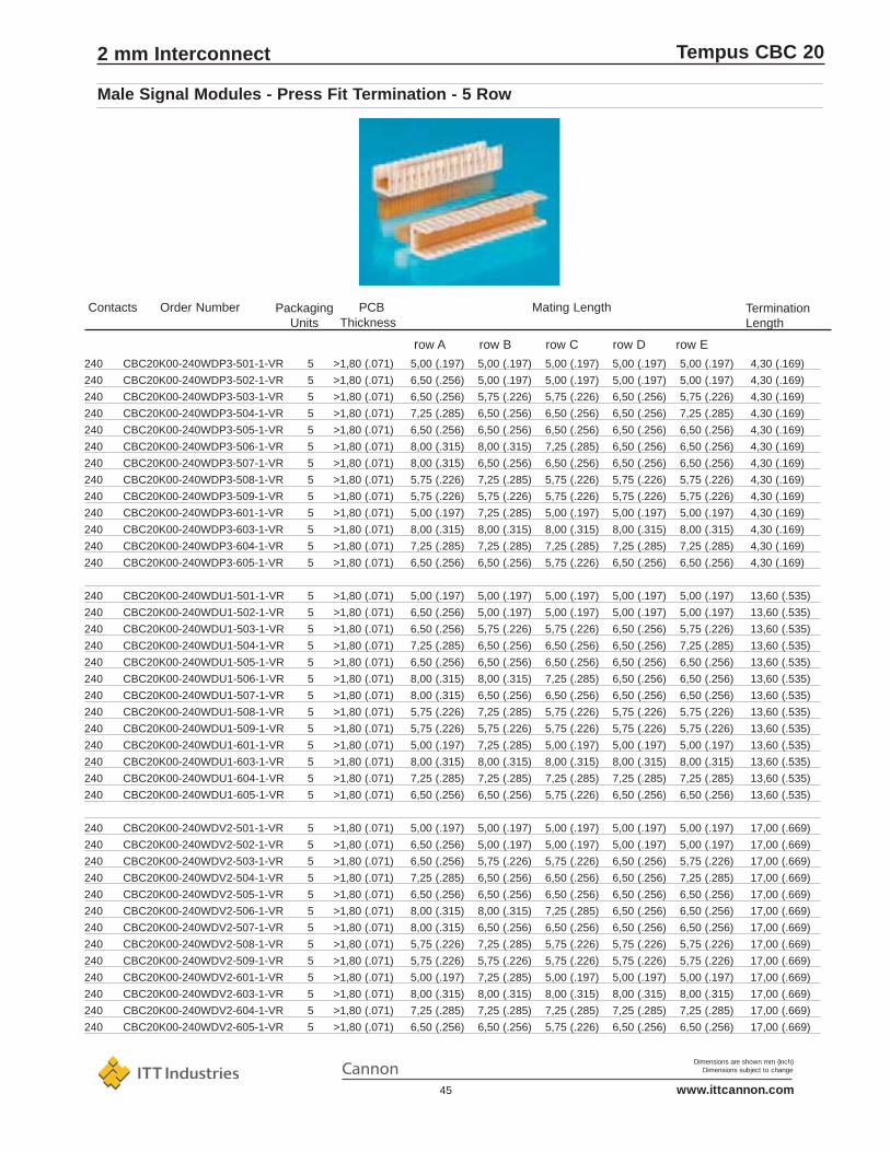
Dimensions are shown mm (inch)Dimensions subject to change
www.ittcannon.com45
Tempus CBC 20
240 CBC20K00-240WDP3-501-1-VR 5 >1,80 (.071) 5,00 (.197) 5,00 (.197) 5,00 (.197) 5,00 (.197) 5,00 (.197) 4,30 (.169)
240 CBC20K00-240WDP3-502-1-VR 5 >1,80 (.071) 6,50 (.256) 5,00 (.197) 5,00 (.197) 5,00 (.197) 5,00 (.197) 4,30 (.169)
240 CBC20K00-240WDP3-503-1-VR 5 >1,80 (.071) 6,50 (.256) 5,75 (.226) 5,75 (.226) 6,50 (.256) 5,75 (.226) 4,30 (.169)
240 CBC20K00-240WDP3-504-1-VR 5 >1,80 (.071) 7,25 (.285) 6,50 (.256) 6,50 (.256) 6,50 (.256) 7,25 (.285) 4,30 (.169)
240 CBC20K00-240WDP3-505-1-VR 5 >1,80 (.071) 6,50 (.256) 6,50 (.256) 6,50 (.256) 6,50 (.256) 6,50 (.256) 4,30 (.169)
240 CBC20K00-240WDP3-506-1-VR 5 >1,80 (.071) 8,00 (.315) 8,00 (.315) 7,25 (.285) 6,50 (.256) 6,50 (.256) 4,30 (.169)
240 CBC20K00-240WDP3-507-1-VR 5 >1,80 (.071) 8,00 (.315) 6,50 (.256) 6,50 (.256) 6,50 (.256) 6,50 (.256) 4,30 (.169)
240 CBC20K00-240WDP3-508-1-VR 5 >1,80 (.071) 5,75 (.226) 7,25 (.285) 5,75 (.226) 5,75 (.226) 5,75 (.226) 4,30 (.169)
240 CBC20K00-240WDP3-509-1-VR 5 >1,80 (.071) 5,75 (.226) 5,75 (.226) 5,75 (.226) 5,75 (.226) 5,75 (.226) 4,30 (.169)
240 CBC20K00-240WDP3-601-1-VR 5 >1,80 (.071) 5,00 (.197) 7,25 (.285) 5,00 (.197) 5,00 (.197) 5,00 (.197) 4,30 (.169)
240 CBC20K00-240WDP3-603-1-VR 5 >1,80 (.071) 8,00 (.315) 8,00 (.315) 8,00 (.315) 8,00 (.315) 8,00 (.315) 4,30 (.169)
240 CBC20K00-240WDP3-604-1-VR 5 >1,80 (.071) 7,25 (.285) 7,25 (.285) 7,25 (.285) 7,25 (.285) 7,25 (.285) 4,30 (.169)
240 CBC20K00-240WDP3-605-1-VR 5 >1,80 (.071) 6,50 (.256) 6,50 (.256) 5,75 (.226) 6,50 (.256) 6,50 (.256) 4,30 (.169)
240 CBC20K00-240WDU1-501-1-VR 5 >1,80 (.071) 5,00 (.197) 5,00 (.197) 5,00 (.197) 5,00 (.197) 5,00 (.197) 13,60 (.535)
240 CBC20K00-240WDU1-502-1-VR 5 >1,80 (.071) 6,50 (.256) 5,00 (.197) 5,00 (.197) 5,00 (.197) 5,00 (.197) 13,60 (.535)
240 CBC20K00-240WDU1-503-1-VR 5 >1,80 (.071) 6,50 (.256) 5,75 (.226) 5,75 (.226) 6,50 (.256) 5,75 (.226) 13,60 (.535)
240 CBC20K00-240WDU1-504-1-VR 5 >1,80 (.071) 7,25 (.285) 6,50 (.256) 6,50 (.256) 6,50 (.256) 7,25 (.285) 13,60 (.535)
240 CBC20K00-240WDU1-505-1-VR 5 >1,80 (.071) 6,50 (.256) 6,50 (.256) 6,50 (.256) 6,50 (.256) 6,50 (.256) 13,60 (.535)
240 CBC20K00-240WDU1-506-1-VR 5 >1,80 (.071) 8,00 (.315) 8,00 (.315) 7,25 (.285) 6,50 (.256) 6,50 (.256) 13,60 (.535)
240 CBC20K00-240WDU1-507-1-VR 5 >1,80 (.071) 8,00 (.315) 6,50 (.256) 6,50 (.256) 6,50 (.256) 6,50 (.256) 13,60 (.535)
240 CBC20K00-240WDU1-508-1-VR 5 >1,80 (.071) 5,75 (.226) 7,25 (.285) 5,75 (.226) 5,75 (.226) 5,75 (.226) 13,60 (.535)
240 CBC20K00-240WDU1-509-1-VR 5 >1,80 (.071) 5,75 (.226) 5,75 (.226) 5,75 (.226) 5,75 (.226) 5,75 (.226) 13,60 (.535)
240 CBC20K00-240WDU1-601-1-VR 5 >1,80 (.071) 5,00 (.197) 7,25 (.285) 5,00 (.197) 5,00 (.197) 5,00 (.197) 13,60 (.535)
240 CBC20K00-240WDU1-603-1-VR 5 >1,80 (.071) 8,00 (.315) 8,00 (.315) 8,00 (.315) 8,00 (.315) 8,00 (.315) 13,60 (.535)
240 CBC20K00-240WDU1-604-1-VR 5 >1,80 (.071) 7,25 (.285) 7,25 (.285) 7,25 (.285) 7,25 (.285) 7,25 (.285) 13,60 (.535)
240 CBC20K00-240WDU1-605-1-VR 5 >1,80 (.071) 6,50 (.256) 6,50 (.256) 5,75 (.226) 6,50 (.256) 6,50 (.256) 13,60 (.535)
240 CBC20K00-240WDV2-501-1-VR 5 >1,80 (.071) 5,00 (.197) 5,00 (.197) 5,00 (.197) 5,00 (.197) 5,00 (.197) 17,00 (.669)
240 CBC20K00-240WDV2-502-1-VR 5 >1,80 (.071) 6,50 (.256) 5,00 (.197) 5,00 (.197) 5,00 (.197) 5,00 (.197) 17,00 (.669)
240 CBC20K00-240WDV2-503-1-VR 5 >1,80 (.071) 6,50 (.256) 5,75 (.226) 5,75 (.226) 6,50 (.256) 5,75 (.226) 17,00 (.669)
240 CBC20K00-240WDV2-504-1-VR 5 >1,80 (.071) 7,25 (.285) 6,50 (.256) 6,50 (.256) 6,50 (.256) 7,25 (.285) 17,00 (.669)
240 CBC20K00-240WDV2-505-1-VR 5 >1,80 (.071) 6,50 (.256) 6,50 (.256) 6,50 (.256) 6,50 (.256) 6,50 (.256) 17,00 (.669)
240 CBC20K00-240WDV2-506-1-VR 5 >1,80 (.071) 8,00 (.315) 8,00 (.315) 7,25 (.285) 6,50 (.256) 6,50 (.256) 17,00 (.669)
240 CBC20K00-240WDV2-507-1-VR 5 >1,80 (.071) 8,00 (.315) 6,50 (.256) 6,50 (.256) 6,50 (.256) 6,50 (.256) 17,00 (.669)
240 CBC20K00-240WDV2-508-1-VR 5 >1,80 (.071) 5,75 (.226) 7,25 (.285) 5,75 (.226) 5,75 (.226) 5,75 (.226) 17,00 (.669)
240 CBC20K00-240WDV2-509-1-VR 5 >1,80 (.071) 5,75 (.226) 5,75 (.226) 5,75 (.226) 5,75 (.226) 5,75 (.226) 17,00 (.669)
240 CBC20K00-240WDV2-601-1-VR 5 >1,80 (.071) 5,00 (.197) 7,25 (.285) 5,00 (.197) 5,00 (.197) 5,00 (.197) 17,00 (.669)
240 CBC20K00-240WDV2-603-1-VR 5 >1,80 (.071) 8,00 (.315) 8,00 (.315) 8,00 (.315) 8,00 (.315) 8,00 (.315) 17,00 (.669)
240 CBC20K00-240WDV2-604-1-VR 5 >1,80 (.071) 7,25 (.285) 7,25 (.285) 7,25 (.285) 7,25 (.285) 7,25 (.285) 17,00 (.669)
240 CBC20K00-240WDV2-605-1-VR 5 >1,80 (.071) 6,50 (.256) 6,50 (.256) 5,75 (.226) 6,50 (.256) 6,50 (.256) 17,00 (.669)
Male Signal Modules - Press Fit Termination - 5 Row
2 mm Interconnect
Mating LengthPackagingUnits
PCBThickness
Termination Length
Contacts Order Number
row A row B row C row D row E

Dimensions are shown mm (inch)Dimensions subject to change
www.ittcannon.com46
Tempus CBC 20
4,00 A at 25°C; 3,00 A at 70°C
1000 Vrms
Initial: 5000MΩ; after climatic test: 1000 MΩ25 mΩ maximum
Current Rating
Withstanding Voltage
Insulation Resistance
Contact Resistance
Contact Pitch
Polarisation
Coding
Housing Material
Termination solder
Termination p.t.h. (solder)
Termination Press Fit
Termination p.t.h. (press fit)
Board Guiding Left to Right
Top to Bottom
Board Slot Pitch
Contact Material
Hertz Stress
Class 1
Plating
Insertion Force
Withdrawal Force
Technical DataMechanical Data
2,00 x 2,00 (.079 x .079)
By design
With coding key, see page 64
Liquid Crystal Polymer, UL94V-0 or PPS. UL94V-0
Solder tail, tin / lead plated
ø 0,60 (.024), refer to page 73
Eye of the needle compliant section, tin/lead plated
ø 0,70 (.028) refer to page 73
2,50 - 2,50 (.100 - .100)
1,50 - 1,50 (.060 - .060)
16,00 (.630) min.
Solder Contact: brass; press fit contact: phosphor bronze
1200 MPa (174 klbf / sq. in.)
1000 cycles minimum
Palladium Nickel plus Gold over Nickel
1,50 N (1.6 oz) max. per contact
0,30 N (0,5 oz) min. per contact
Male Power Modules - Press Fit/Solder Termination - 5 Row
• Wide wall design for system tolerant2,50 (.098) out-of-centre board insertion
• High temperature materials, not affected by reflow solder process
• Sequential mating provides live insertion capability
• High performance contacts, high hertz stress, 1000 cycles minimum
• Designed to conform with IEC61076-4-104, EIAis64, IEEE P896 Futurebus+, IEEE P1596 SCI and IEC 917 metric modular order
• Stackable with other TEMPUS modules, with no loss of positions
Features
2 mm Interconnect
Electrical Data

Dimensions are shown mm (inch)Dimensions subject to change
www.ittcannon.com47
Tempus CBC 20
17,80(.701)
13,50(.532)
6,50(.256)
2,00(.079)
6,10(.240)
17,00(.669)
2,88(.113)
4,30 Pressfit Length(.169)
4,60 Solder Tail Length(.181)
14,00(.551)
2,00(.079)
2,00(.079)
Ø0,60(.024)
Ø1,30(.051)
10,00(.394)
18,00 MIN(.709)
2,00(.079)
18,00 MIN(.709)
0,70(.028)
2,00(.079)
8,00(.315)
Recommended PCB Hole PatternComponent Side
10 Contacts
2 5
2,00(.079)
6,00(.238)
11,94(.470)
Male Power Modules - Press Fit/Solder Termination - 5 Row
2 mm Interconnect

Dimensions are shown mm (inch)Dimensions subject to change
www.ittcannon.com48
Tempus CBC 20
10 CBC20K90-010WDP1-504-1-VR 44 >1,80 (.071) 7,25 (.285) 6,50 (.256) 6,50 (.256) 6,50 (.256) 7,25 (.285) 4,30 (.169)
10 CBC20K90-010WDP1-505-1-VR 44 >1,80 (.071) 6,50 (.256) 6,50 (.256) 6,50 (.256) 6,50 (.256) 6,50 (.256) 4,30 (.169)
10 CBC20K90-010WDP1-506-1-VR 44 >1,80 (.071) 8,00 (.315) 8,00 (.315) 7,25 (.285) 6,50 (.256) 6,50 (.256) 4,30 (.169)
10 CBC20K90-010WDP1-507-1-VR 44 >1,80 (.071) 8,00 (.315) 6,50 (.256) 6,50 (.256) 6,50 (.256) 6,50 (.256) 4,30 (.169)
10 CBC20K90-010WDP1-603-1-VR 44 >1,80 (.071) 8,00 (.315) 8,00 (.315) 8,00 (.315) 8,00 (.315) 8,00 (.315) 4,30 (.169)
10 CBC20K90-010WDP1-604-1-VR 44 >1,80 (.071) 7,25 (.285) 7,25 (.285) 7,25 (.285) 7,25 (.285) 7,25 (.285) 4,30 (.169)
10 CBC20K90-010WDP3-504-1-VR 44 >1,80 (.071) 7,25 (.285) 6,50 (.256) 6,50 (.256) 6,50 (.256) 7,25 (.285) 4,30 (.169)
10 CBC20K90-010WDP3-505-1-VR 44 >1,80 (.071) 6,50 (.256) 6,50 (.256) 6,50 (.256) 6,50 (.256) 6,50 (.256) 4,30 (.169)
10 CBC20K90-010WDP3-506-1-VR 44 >1,80 (.071) 8,00 (.315) 8,00 (.315) 7,25 (.285) 6,50 (.256) 6,50 (.256) 4,30 (.169)
10 CBC20K90-010WDP3-507-1-VR 44 >1,80 (.071) 8,00 (.315) 6,50 (.256) 6,50 (.256) 6,50 (.256) 6,50 (.256) 4,30 (.169)
10 CBC20K90-010WDP3-603-1-VR 44 >1,80 (.071) 8,00 (.315) 8,00 (.315) 8,00 (.315) 8,00 (.315) 8,00 (.315) 4,30 (.169)
10 CBC20K90-010WDP3-604-1-VR 44 >1,80 (.071) 7,25 (.285) 7,25 (.285) 7,25 (.285) 7,25 (.285) 7,25 (.285) 4,30 (.169)
10 CBC20K90-010WDU1-504-1-VR 44 >1,80 (.071) 7,25 (.285) 6,50 (.256) 6,50 (.256) 6,50 (.256) 7,25 (.285) 13,60 (.535)
10 CBC20K90-010WDU1-505-1-VR 44 >1,80 (.071) 6,50 (.256) 6,50 (.256) 6,50 (.256) 6,50 (.256) 6,50 (.256) 13,60 (.535)
10 CBC20K90-010WDU1-506-1-VR 44 >1,80 (.071) 8,00 (.315) 8,00 (3.15) 7,25 (.285) 6,50 (.256) 6,50 (.256) 13,60 (.535)
10 CBC20K90-010WDU1-507-1-VR 44 >1,80 (.071) 8,00 (.315) 6,50 (.256) 6,50 (.256) 6,50 (.256) 6,50 (.256) 13,60 (.535)
10 CBC20K90-010WDU1-603-1-VR 44 >1,80 (.071) 8,00 (.315) 8,00 (.315) 8,00 (.315) 8,00 (.315) 8,00 (.315) 13,60 (.535)
10 CBC20K90-010WDU1-604-1-VR 44 >1,80 (.071) 7,25 (.285) 7,25 (.285) 7,25 (.285) 7,25 (.285) 7,25 (.285) 13,60 (.535)
10 CBC20K90-010WDV2-504-1-VR 44 >1,80 (.071) 7,25 (.285) 6,50 (.256) 6,50 (.256) 6,50 (.256) 7,25 (.285) 17,00 (.669)
10 CBC20K90-010WDV2-505-1-VR 44 >1,80 (.071) 6,50 (.256) 6,50 (.256) 6,50 (.256) 6,50 (.256) 6,50 (.256) 17,00 (.669)
10 CBC20K90-010WDV2-506-1-VR 44 >1,80 (.071) 8,00 (.315) 8,00 (.315) 7,25 (.285) 6,50 (.256) 6,50 (.256) 17,00 (.669)
10 CBC20K90-010WDV2-507-1-VR 44 >1,80 (.071) 8,00 (.315) 6,50 (.256) 6,50 (.256) 6,50 (.256) 6,50 (.256) 17,00 (.669)
10 CBC20K90-010WDV2-603-1-VR 44 >1,80 (.071) 8,00 (.315) 8,00 (.315) 8,00 (.315) 8,00 (.315) 8,00 (.315) 17,00 (.669)
10 CBC20K90-010WDV2-604-1-VR 44 >1,80 (.071) 7,25 (.285 7,25 (.285) 7,25 (.285) 7,25 (.285) 7,25 (.285) 17,00 (.669)
10 CBC20K90-010WDS1-504-1-VR 44 3,20 (.126) 7,25 (.285) 6,50 (.256) 6,50 (.256) 6,50 (.256) 7,25 (.285) 4,60 (.181)
10 CBC20K90-010WDS1-505-1-VR 44 3,20 (.126) 6,50 (.256) 6,50 (.256) 6,50 (.256) 6,50 (.256) 6,50 (.256) 4,60 (.181)
10 CBC20K90-010WDS1-506-1-VR 44 3,20 (.126) 8,00 (.315) 8,00 (.315) 7,25 (.285) 6,50 (.256) 6,50 (.256) 4,60 (.181)
10 CBC20K90-010WDS1-507-1-VR 44 3,20 (.126) 8,00 (.315) 6,50 (.256) 6,50 (.256) 6,50 (.256) 6,50 (.256) 4,60 (.181)
10 CBC20K90-010WDS1-603-1-VR 44 3,20 (.126) 8,00 (.315) 8,00 (.315) 8,00 (.315) 8,00 (.315) 8,00 (.315) 4,60 (.181)
10 CBC20K90-010WDS1-604-1-VR 44 3,20 (.126) 8,00 (.315) 7,25 (.285) 7,25 (.285) 7,25 (.285) 7,25 (.285) 4,60 (.181)
10 CBC20K90-010WDS2-504-1-VR 44 2,40 (.094) 7,25 (.285) 6,50 (.256) 6,50 (.256) 6,50 (.256) 7,25 (.285) 3,60 (.142)
10 CBC20K90-010WDS2-505-1-VR 44 2,40 (.094) 6,50 (.256) 6,50 (.256) 6,50 (.256) 6,50 (.256) 6,50 (.256) 3,60 (.142)
10 CBC20K90-010WDS2-506-1-VR 44 2,40 (.094) 8,00 (.315) 8,00 (.315) 7,25 (.285) 6,50 (.256) 6,50 (.256) 3,60 (.142)
10 CBC20K90-010WDS2-507-1-VR 44 2,40 (.094) 8,00 (.315) 6,50 (.256) 6,50 (.256) 6,50 (.256) 6,50 (.256) 3,60 (.142)
10 CBC20K90-010WDS2-603-1-VR 44 2,40 (.094) 8,00 (.315) 8,00 (.315) 8,00 (.315) 8,00 (.315) 8,00 (.315) 3,60 (.142)
10 CBC20K90-010WDS2-604-1-VR 44 2,40 (.094) 7,25 (.285) 7,25 (.256) 7,25 (.285) 7,25 (.285) 7,25 (.285) 3,60 (.142)
Male Power Modules - Press Fit/Solder Termination - 5 Row
2 mm Interconnect
Mating LengthPackagingUnits
PCBThickness
Termination Length
Contacts Order Number
row A row B row C row D row E

Dimensions are shown mm (inch)Dimensions subject to change
www.ittcannon.com49
Tempus CBC 20
1,50 A at 25°C; 1,00 A at 70°C
1000 Vrms
Initial: 5000MΩ; after climatic test: 1000 MΩ45 mΩ maximum
Current Rating
Withstanding Voltage
Insulation Resistance
Contact Resistance
Electrical Data
Contact Pitch
Polarisation
Coding
Housing Material
Termination Solder
Termination p.t.h.(solder)
Termination Press-fit
Termination p.t.h. (press-fit)
Board Retention
Board Guiding Left to Right
Top to Bottom
Board Slot Pitch
Contact Material
Hertz Stress
Class 1
Plating
Insertion Force
Withdrawal Force
Technical DataMechanical Data
2,00 x 2,00 (.079 x .079)
By design
With coding key, see page 64
Liquid Crystal Polymer, UL94V-0 or PPS, UL94V-0
Solder tail, tin/lead plated
ø 0,60 (.024), refer to page 73
Eye of needle compliant section, tin/lead plated
ø 0,70 (.028), refer to page 73
Pushfit peg or heat stake
2,50 - 2,50 (.100 - .100)
1,50 - 1,50 (.060 - .060)
16,00 (.630) min.
Phosphor bronze
1200 MPa (174 klbf / sq. in.)
1000 cycles minimum
Palladium Nickel plus Gold over Nickel
0,45 N (1.6 oz) max. per contact
0,15 N (0,5 oz) min. per contact
Male Right-Angle Signal Module - Wide Wall - Solder and Pressfit Termination - 4 Row
• High temperature materials, not affected by reflow solder process
• Wide wall design for system tolerant2,50 (.098) out-of-centre board insertion
• 45° legform for optimum electrical performance
• High performance contacts, high hertz stress, 1000 cycles minimum
• High I/O, 20 contacts per linear centimetre (51 contacts per linear inch)
• Designed to conform with IEC61076-4-104, EIAis64, IEEE P896 Futurebus+, IEEE P1596 SCI and IEC 917 metric modular order
• Stackable with other TEMPUS modules, with no loss of positions
Features
2 mm Interconnect

Dimensions are shown mm (inch)Dimensions subject to change
www.ittcannon.com50
Tempus CBC 20
PC Board Hole Pattern
Version P1-002Push-fit Peg Mounting
Version S1(Heat Staking)
Terminals Tinned
Contact In Tube
24 44
Packaging Quantity
All part numbers refer to connectorssupplied in tubes.
Note:
Minimum order quantities apply
Performance 1000 mating cycles min
* Part numbers in blue letters typeface indicate standard products: usually available with shorter lead times.
No. of Part Number* Board Termination Retention Contact Arrangement RowContacts Thickness a b c d
24 CBC20A00-024BDP1-1-1-002-VR 1,60 (.063) Pressfit Pushfit Peg 5,00 (.197) 5,00 (.197) 5,00 (.197) 5,00 (.197)24 CBC20A00-024BDS1-1-1-002-VR 1,60 (.063) Solder Pushfit Peg 5,00 (.197) 5,00 (.197) 5,00 (.197) 5,00 (.197)24 CBC20A00-024BDS1-1-1-VR 1,60 (.063 Solder Heat Stake 5,00 (.197) 5,00 (.197) 5,00 (.197) 5,00 (.197)24 CBC20A00-024BDP1-5-1-002-VR 1,60 (.063) Pressfit Pushfit Peg 6,50 (.256) 6,50 (.256) 6,50 (.256) 6,50 (.256)24 CBC20A00-024BDS1-5-1-002-VR 1,60 (.063) Solder Pushfit Peg 6,50 (.256) 6,50 (.256) 6,50 (.256) 6,50 (.256)24 CBC20A00-024BDS1-5-1-VR 1,60 (.063) Solder Heat Stake 6,50 (.256) 6,50 (.256) 6,50 (.256) 6,50 (.256)
Male Right-Angle Signal Module - Wide Wall - Solder and Pressfit Termination - 4 Row
2 mm Interconnect

Dimensions are shown mm (inch)Dimensions subject to change
www.ittcannon.com51
Tempus CBC 20
4,00 A at 25°C, 3,00 A at 70°C
1000 Vrms
Initial: 5000MΩ, after climatic test: 1000 MΩ25 mΩ maximum
Current Rating
Withstanding Voltage
Insulation Resistance
Contact Resistance
Contact Pitch
Polarisation
Coding
Housing Material
Termination solder
Termination p.t.h. (solder)
Termination Press Fit
Termination p.t.h. (press fit)
Board Guiding Left to Right
Top to Bottom
Board Slot Pitch
Contact Material
Hertz Stress
Class 1
Plating
Insertion Force
Withdrawal Force
Technical DataMechanical Data
2,00 x 2,00 (.079 x .079)
By design
With coding key, see page 64
Liquid Crystal Polymer, UL94V-0 or PPS. UL94V-0
Solder tail, tin / lead plated
ø 0,60 (.024), refer to page 73
Eye of the needle compliant section, tin/lead plated
ø 0,70 (.028) refer to page 73
2,50 - 2,50 (.100 - .100)
1,50 - 1,50 (.060 - .060)
16,00 (.630) min.
Solder Contact: brass, press fit contact: phosphor bronze
1200 MPa (174 klbf / sq. in.)
1000 cycles minimum
Palladium Nickel plus Gold over Nickel
1,50 N (1.6 oz) max. per contact
0,30 N (0,5 oz) min. per contact
• Wide wall design for system tolerant2,50 (.098) out-of-centre board insertion
• High temperature materials, not affected by reflow solder process
• Sequential mating provides live insertion capability
• High performance contacts, high hertz stress, 1000 cycles minimum
• Designed to conform with IEC61076-4-104, EIAis64, IEEE P896 Futurebus+, IEEE P1596 SCI and IEC 917 metric modular order
• Stackable with other TEMPUS modules, with no loss of positions
Features
Male Right-Angle Power Module - Wide Wall - Solder and Pressfit Termination - 4 Row
2 mm Interconnect
Electrical Data
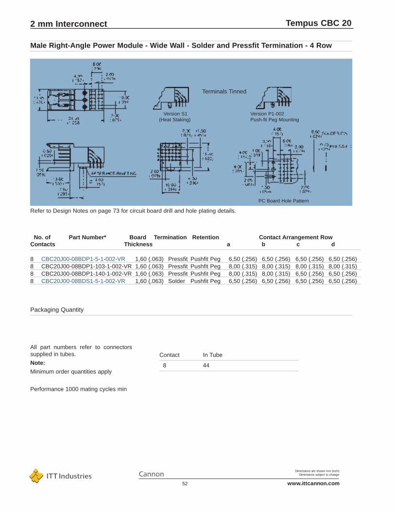
Dimensions are shown mm (inch)Dimensions subject to change
www.ittcannon.com52
Tempus CBC 20
PC Board Hole Pattern
Refer to Design Notes on page 73 for circuit board drill and hole plating details.
Contact In Tube
8 44
Packaging Quantity
All part numbers refer to connectorssupplied in tubes.
Note:
Minimum order quantities apply
Performance 1000 mating cycles min
No. of Part Number* Board Termination Retention Contact Arrangement RowContacts Thickness a b c d
8 CBC20J00-08BDP1-5-1-002-VR 1,60 (.063) Pressfit Pushfit Peg 6,50 (.256) 6,50 (.256) 6,50 (.256) 6,50 (.256)8 CBC20J00-08BDP1-103-1-002-VR 1,60 (.063) Pressfit Pushfit Peg 8,00 (.315) 8,00 (.315) 8,00 (.315) 8,00 (.315)8 CBC20J00-08BDP1-140-1-002-VR 1,60 (.063) Pressfit Pushfit Peg 8,00 (.315) 8,00 (.315) 6,50 (.256) 6,50 (.256)8 CBC20J00-08BDS1-5-1-002-VR 1,60 (.063) Solder Pushfit Peg 6,50 (.256) 6,50 (.256) 6,50 (.256) 6,50 (.256)
Male Right-Angle Power Module - Wide Wall - Solder and Pressfit Termination - 4 Row
2 mm Interconnect
Version P1-002Push-fit Peg Mounting
Version S1(Heat Staking)
Terminals Tinned
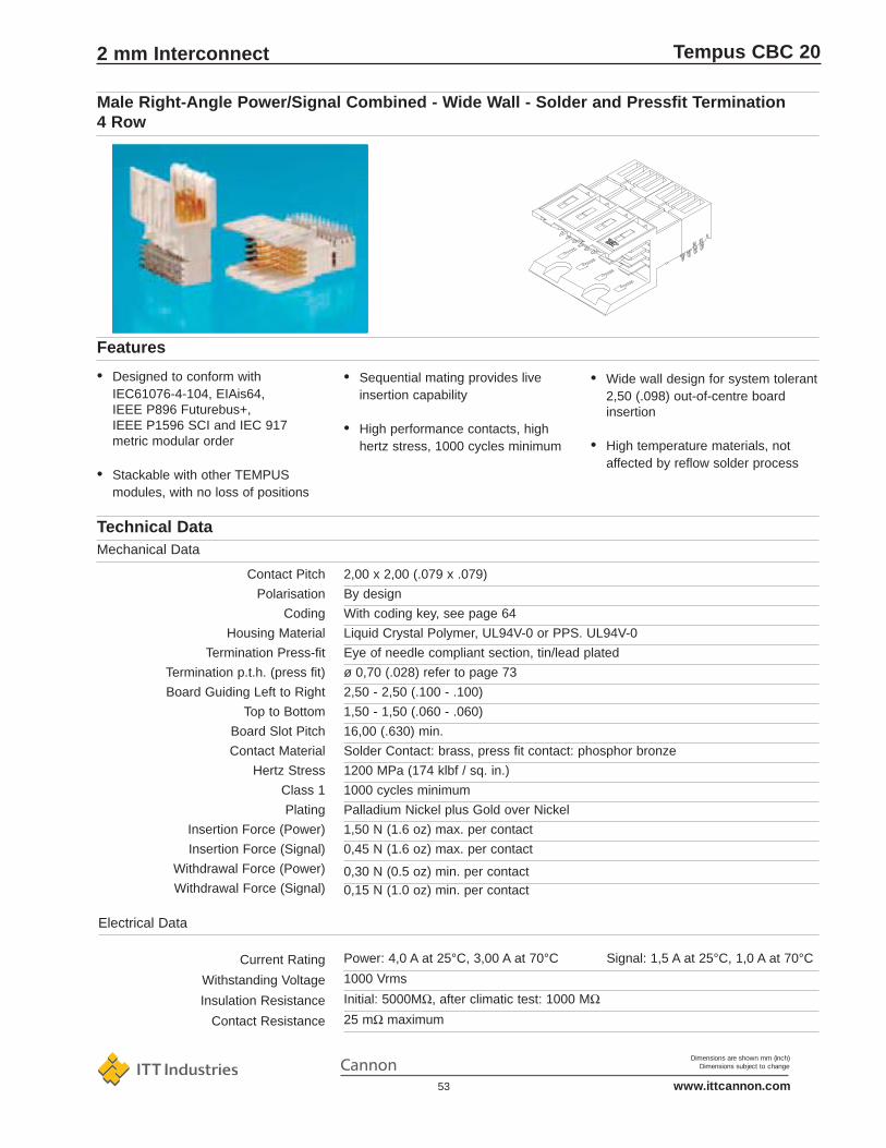
Dimensions are shown mm (inch)Dimensions subject to change
www.ittcannon.com53
Tempus CBC 20
Power: 4,0 A at 25°C, 3,00 A at 70°C Signal: 1,5 A at 25°C, 1,0 A at 70°C
1000 Vrms
Initial: 5000MΩ, after climatic test: 1000 MΩ25 mΩ maximum
Current Rating
Withstanding Voltage
Insulation Resistance
Contact Resistance
Contact Pitch
Polarisation
Coding
Housing Material
Termination Press-fit
Termination p.t.h. (press fit)
Board Guiding Left to Right
Top to Bottom
Board Slot Pitch
Contact Material
Hertz Stress
Class 1
Plating
Insertion Force (Power)
Insertion Force (Signal)
Withdrawal Force (Power)
Withdrawal Force (Signal)
Technical DataMechanical Data
2,00 x 2,00 (.079 x .079)
By design
With coding key, see page 64
Liquid Crystal Polymer, UL94V-0 or PPS. UL94V-0
Eye of needle compliant section, tin/lead plated
ø 0,70 (.028) refer to page 73
2,50 - 2,50 (.100 - .100)
1,50 - 1,50 (.060 - .060)
16,00 (.630) min.
Solder Contact: brass, press fit contact: phosphor bronze
1200 MPa (174 klbf / sq. in.)
1000 cycles minimum
Palladium Nickel plus Gold over Nickel
1,50 N (1.6 oz) max. per contact
0,45 N (1.6 oz) max. per contact
0,30 N (0.5 oz) min. per contact0,15 N (1.0 oz) min. per contact
• Wide wall design for system tolerant2,50 (.098) out-of-centre board insertion
• High temperature materials, not affected by reflow solder process
• Sequential mating provides live insertion capability
• High performance contacts, high hertz stress, 1000 cycles minimum
• Designed to conform with IEC61076-4-104, EIAis64, IEEE P896 Futurebus+, IEEE P1596 SCI and IEC 917 metric modular order
• Stackable with other TEMPUS modules, with no loss of positions
Features
Male Right-Angle Power/Signal Combined - Wide Wall - Solder and Pressfit Termination 4 Row
2 mm Interconnect
Electrical Data

Dimensions are shown mm (inch)Dimensions subject to change
www.ittcannon.com54
Tempus CBC 20
1,50
(0.0
59)
0,50
(0.0
2)
1,40
(0.0
55)
32,00(1.260)
13,6(.535)
7,5(.295)
4,00(.157)
6,00(.236)
3,00
(0.1
18)
3,00
(0.1
18)
9,35
(0.3
68)
22,00(.866)
3,00(0.118)
10,00(0.157)
3,00(0.118)
10,00(0.394)
23,98 max.(.944)
3,00(0.118)
5,0
(0.1
97)
12,0
(0.4
72)
(0.0
81±0
.002
)2,
05±0
,05
6,00(.236)
2,00(.079)
(0.0
28±0
.002
)
Recommended P.C.B. Hole Pattern,Component Side
0,71
±0,0
6
No. of Part Number Board Termination Retention Contact Arrangement RowContacts Thickness a b c d
32 CBC20Z15-032BDP1-15-1-002-VR 1,60 (.063) Pressfit Pushfit Peg Signal
5,00 5,00 5,00 5,00 (.197) (.197) (.197) (.197)
Power
6,50 6,50 6,50 6,50 (.256) (.256) (.256) (.256)
32 CBC120210-149 1,60 (.063) Pressfit Pushfit Peg Signal
5,00 5,00 5,00 5,00 (.197) (.197) (.197) (.197)
Power column 8 all contacts = 8,00 (.315)
Power column 11 all contacts = 6,50 (.256)
Male Right-Angle Power/Signal Combined - Wide Wall - Solder and Pressfit Termination4 Row
2 mm Interconnect

Dimensions are shown mm (inch)Dimensions subject to change
www.ittcannon.com55
Tempus CBC 20
4,00 A at 25°C, 3,00 A at 70°C
1000 Vrms
Initial: 5000MΩ, after climatic test: 1000 MΩ25 mΩ maximum
Current Rating
Withstanding Voltage
Insulation Resistance
Contact Resistance
Electrical Data
Contact Pitch
Polarisation
Coding
Housing Material
Termination Press Fit
Termination p.t.h.
Contact Material
Hertz Stress
Class 1
Plating
Insertion Force
Withdrawal Force
Technical DataMechanical Data
2,00 x 2,00 (.079 x .079)
By design
With coding key, see page 64
Liquid Crystal Polymer, UL94V-0 or PPS, UL94V-0
Eye of the needle compliant section, tin/lead plated
ø 0,70 (.028) refer to page 73
Phosphor Bronze
1200 MPa (174 klbf / sq. in.)
1000 cycles minimum
Palladium Nickel plus Gold over Nickel
1,50 N (1.6 oz) max. per contact
0,30 N (0,5 oz) min. per contact
• 45° tails for mechanical stability andelectrical performance
• High temperature materials, not affected by reflow solder process
• Press fit with push fit retention, solder with heat stake or push fit
• High performance contacts, high hertz stress, 1000 cycles minimum
• Designed to conform with IEC 61076-4-104, EIAis64, IEEE P896 Futurebus+, IEEE P1596 SCI and IEC 917 metric modular order
• Stackable with other TEMPUS modules, with no loss of positions
Features
Female Straight Power Module - Pressfit Termination - 4 Row
2 mm Interconnect

Dimensions are shown mm (inch)Dimensions subject to change
www.ittcannon.com56
Tempus CBC 20
0,71
±0,0
6
(.02
8±0.
002)
2,00
(.07
9)
6,00(.236)
2,00(.079)
0,95(.037)
14,30(.563)
6,00(.236)
1,50
(0.0
59)11
,98
max
. (0
.472
)
14,0
0(.
551)
11,8
5(.
467)
11,3
0(.
445)
2,00
(.07
9)6,
00
(.23
6)
0,35
(.01
4)
10,0
0(.
394)
2,00
(.07
9)
4,30 min.(.169)
Contact In Tube
8 44
Packaging Quantity
Performance 1000 mating cycles
Note:
Minimum order quantities apply
No. of Part Number BoardContacts Thickness
8 CBC20RP00-008FDP1-0-1 (VR) 1,60 (.063)
Female Straight Power Module - Pressfit Termination - 4 Row
2 mm Interconnect

Dimensions are shown mm (inch)Dimensions subject to change
www.ittcannon.com57
Tempus CBC 20
1,50 A at 25°C, 1,00 A at 70°C
1000 Vrms
Initial: 5000MΩ, after climatic test: 1000 MΩ45 mΩ maximum
Current Rating
Withstanding Voltage
Insulation Resistance
Contact Resistance
Electrical Data (when assembled)
Contact Pitch
Polarisation
Coding
Housing Material
Board Retention
Board Guiding Left to Right
Top to Bottom
Board Slot Pitch
Styles
Technical DataMechanical Data
2,00 x 2,00 (.079 x .079)
By design
With coding key, see page 65
Liquid Crystal Polymer, UL94V-0 or PPS, UL94V-0
Press-fit on rear of backplane onto tails of TEMPUS male press-fit module
2,50 - 2,50 (.100 - .100)
1,50 - 1,50 (.060 - .060)
16,00 (.630) min.
3,40 (.130) base or 7,20 (.280) base with wire wrap
Shrouds
• High temperature materials, not affected by reflow solder process
• Polarisation by design
• Two stand-off options
• Stackable with other TEMPUS modules, with no loss of positions
• Wide wall design for system tolerant 2,50 (.100) out-of-centre board insertion
• High I/O, 20 contacts per linear centimetre (51 contacts per linear inch)
• Designed to conform with IEC61076-4-104, EIAis64, IEEE P896 Futurebus+, IEEE P1596 SCI and IEC 917 metric modular order
• To be used in conjunction with TEMPUS CBC 20 male pressfit long tail modules
Features
2 mm Interconnect

Dimensions are shown mm (inch)Dimensions subject to change
www.ittcannon.com58
Tempus CBC 20
3,40 mm Base Version 7,20 mm Base Version
Packaging Quantity Bulk package only
To select shroud/base required; see page 71
No. of Contacts Part Number* Base Height24 CBC20A00-024WR1 3,40 (.134)24 CBC20A00-024WR3 7,20 (.283)48 CBC20B00-048WR1 3,40 (.134)48 CBC20B00-048WR3 7,20 (.283)72 CBC20X00-072WR1 3,40 (.134)96 CBC20C00-096WR1 3,40 (.134)
Shrouds
2 mm Interconnect
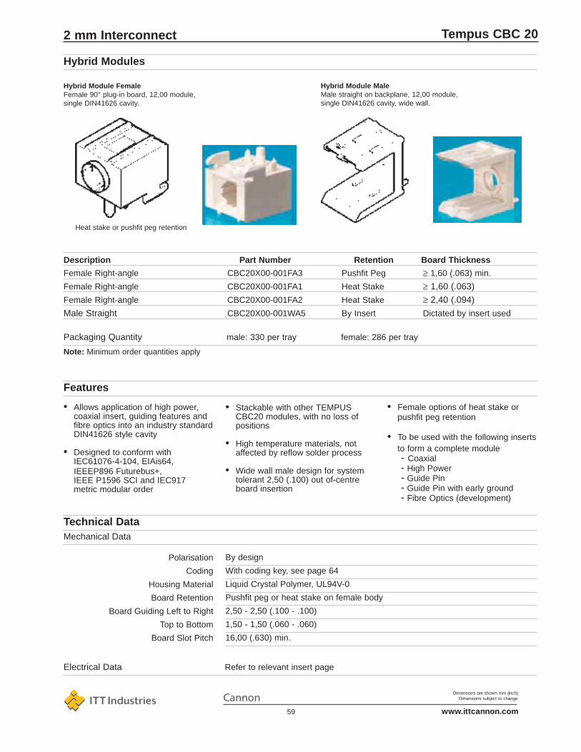
Dimensions are shown mm (inch)Dimensions subject to change
www.ittcannon.com59
Tempus CBC 20
Hybrid Module MaleMale straight on backplane, 12,00 module,single DIN41626 cavity, wide wall.
Heat stake or pushfit peg retention
Hybrid Module FemaleFemale 90° plug-in board, 12,00 module,single DIN41626 cavity.
Note: Minimum order quantities apply
Packaging Quantity male: 330 per tray female: 286 per tray
Description Part Number Retention Board Thickness
Female Right-angle CBC20X00-001FA3 Pushfit Peg ≥ 1,60 (.063) min.
Female Right-angle CBC20X00-001FA1 Heat Stake ≥ 1,60 (.063)
Female Right-angle CBC20X00-001FA2 Heat Stake ≥ 2,40 (.094)
Male Straight CBC20X00-001WA5 By Insert Dictated by insert used
Electrical Data Refer to relevant insert page
By design
With coding key, see page 64
Liquid Crystal Polymer, UL94V-0
Pushfit peg or heat stake on female body
2,50 - 2,50 (.100 - .100)
1,50 - 1,50 (.060 - .060)
16,00 (.630) min.
Polarisation
Coding
Housing Material
Board Retention
Board Guiding Left to Right
Top to Bottom
Board Slot Pitch
Technical DataMechanical Data
• Female options of heat stake or pushfit peg retention
• To be used with the following insertsto form a complete module- Coaxial- High Power- Guide Pin- Guide Pin with early ground- Fibre Optics (development)
• Stackable with other TEMPUS CBC20 modules, with no loss of positions
• High temperature materials, not affected by reflow solder process
• Wide wall male design for system tolerant 2,50 (.100) out of-centre board insertion
• Allows application of high power, coaxial insert, guiding features and fibre optics into an industry standard DIN41626 style cavity
• Designed to conform with IEC61076-4-104, EIAis64, IEEEP896 Futurebus+, IEEE P1596 SCI and IEC917 metric modular order
Features
Hybrid Modules
2 mm Interconnect

Dimensions are shown mm (inch)Dimensions subject to change
www.ittcannon.com60
Tempus CBC 20
Guiding with Ground / E.S.D. Guiding Only
Steel
Steel
Gold
500 cycles minimum
Contact Material Guide Pin on Backplane
Socket on Plug-in Board
Plating
Performance
Insert Mechanical Data
• Guide pin options of- gold plated pin with rear stud
ground tag terminal (e.s.d. capability)
- steel pin with screw to backplane to suit standard female cavity
Contact Pitch
Polarisation
Coding
Housing Material
Board Retention
Socket Termination
Board Guiding Left to Right
Top to Bottom
ESD Pin Retention
Steel Guide Pin Retention
Technical Data Mechanical Data
Single hybrid cavity in a 12 mm module
By design
With coding keys, see page 64
Liquid Crystal Polymer, UL94V-0 or PPS, UL94V-0
Pushfit peg or heat stake on body
Solder to board
2,50 - 2,50 (.100 - .100)
2,50 - 2,50 (.100 - .100)
Nut and Washer
Screw and Washer
• Stackable with other TEMPUS modules, with no loss of positions
• Utilises standard hybrid modules
• Provides a minimum of 2,50 (1.00) out-of-centre misalignment in any direction with early grounding / electro-static discharge capability
Features
Guide Pin / Socket
2 mm Interconnect

Dimensions are shown mm (inch)Dimensions subject to change
www.ittcannon.com61
Tempus CBC 20
Guide Pin CCBC120210-706 should only be used with female monoblocks
Guide Pin withScrewCBC120210-706
Fig. 2Female Hybrid Partof Monoblock
Guide Pin with Ground StudComplete with Nut and WasherCBC120210-705
Fig. 1Grounded SocketCBC120210-701
100 per bag
Note: Minimum order quantities apply.
Packaging Method
Packaging
Current Rating
Insulation Resistance
Technical Data Electrical Data
40 A
Initial: 5000MΩ, after climatic test: 1000MΩ
Guide Pin / Socket Inserts
2 mm Interconnect
Board Details
Dimensions are shown mm (inch)Dimensions subject to change
www.ittcannon.com62
Tempus CBC 20
One bag per assemblyPackaging Method
Packaging
• IDC termination with strain relief
• Wire size of 26 AWG and 30 AWG
• Female contacts for interface to TEMPUS CBC20 male signal modules
• Designed to interface with IEC61076-4-104, EIAis64 style modules and shrouds
Features
1 A
1000 Vrms
Initial: 5000 MΩ, after climatic test: 1000 MΩ
Current Rating
Withstanding Voltage
Insulation Resistance
Electrical Data
Contact Pitch
Basic Design
Housing Material
Termination
Wire
Retention
Contact Specification
Class 3
Plating
Material
Insertion Force
Withdrawal Force
Technical DataMechanical Data
2,00 x 2,00 (.079 x .079)
Snap together terminal block two part for equal wire length, active “press torelease” latch
Body: thermoplastic polyester; Latch: polycarbonate
Insulation displacement, IDC
26 AWG and 30 AWG
Cable tie to body on cable, crimp behind IDC on wires
250 cycles minimum
Gold
Phosphor bronze
0,45 N (1.6 oz) max. per contact
0,15 N (0.5 oz) max. per contact
Cable Connectors, 4 Row
2 mm Interconnect

Dimensions are shown mm (inch)Dimensions subject to change
www.ittcannon.com63
Tempus CBC 20
No. of Contacts Part Number Cable Size (AWG)
24 CBC20C1-024F-W1-3 26
24 CBC20C1-024F-W2-3 28/30
48 CBC20C1-048F-W1-3 26
48 CBC20C1-048F-W2-3 28/30
Note: Minimum order quantities apply
Cable Connectors, 4 Row
2 mm Interconnect

Dimensions are shown mm (inch)Dimensions subject to change
www.ittcannon.com64
Tempus CBC 20
Part Number Description Colour
CBC120210-700 Coding Key set complete codes light blueAF, BF, CF, DF, AM, BM, CM, DM
CBC120210-749 Code Key AF light green
CBC120210-750 Code Key BF light blue
CBC120210-751 Code Key CF pink
CBC120210-752 Code Key DF light brown
CBC120210-745 Code Key AM light green
CBC120210-746 Code Key BM light blue
CBC120210-747 Code Key CM pink
CBC120210-748 Code Key DM light brown
Packaging
Packaging Method As complete key set or separate keys in bagsSeparate keys are supplied 100 keys in a bag complete with holder
Note: Minimum order quantites apply
Material
A simple key may be inserted intoeach 12,00 (.472) length of a moduleor monoblock providing many codingcombinations with a minimum set ofparts.
• Coding with no loss of contact position
• In accordance with IEC48b237 and EIAis64 specifications
Features
Basic Design
Technical DataMechanical Data
Coding keys as defined by IEC61076-4-104 and EIA is64, insert into both halvesof connector, coding without loss of contact position
Liquid Crystal Polymer or PPS, UL94V-0
Coding System
2 mm Interconnect

Dimensions are shown mm (inch)Dimensions subject to change
www.ittcannon.com65
Tempus CBC 20
Break key and holder from frame,insert into connector, than snap offholder.
Code keys used under code clipson female and into code slots onthe male.
Coding System
2 mm Interconnect

Dimensions are shown mm (inch)Dimensions subject to change
www.ittcannon.com66
Tempus CBC 20
produced in accordance with customerrequirements. Please consult yourCannon sales representative or customersupport locations.
• Fewer modules reduces inventory management
• Can feature all parts of the standard modular system plus custom features (such as plastic guide pin etc.)
• Many variations are available, consult Cannon
tools allow custom connectors from standardised tools
• Body and Contact features same asmodules
• Correctly configured in accordance with customer requirement, loweringchance of assembly errors and rework
• Lowers application cost especially involume applications
• Directly replace modular layouts - no board redesign required
• Second sourced by modular layouts
• Unique Cannon modular mould
Features
Due to the unique manufacturing meth-ods employed to produce TEMPUS, awide range of monoblocks many be
Monoblocks are customer tailoredconnectors produced from standardmodule tool and moulded as a singleunit.
Custom Monoblocks
2 mm Interconnect

Dimensions are shown mm (inch)Dimensions subject to change
www.ittcannon.com67
Tempus CBC 20
As Used On
Profile A: General Purpose Multiprocessor SystemsProfile B: General Purpose I/O SystemProfile F: Very High Performance Multiprocessor SystemsProfile T: Telecommunication Systems
• Can be customised to suit customers design variants
• High performance contacts, high hertz stress, 1000 cycles minimum
• 45° female legform provides the shortest stub length and best impedance control, suitable for fast Backplane Transceiver Logic
• Lowers applied cost
• Correct configuration lowers chanceof assembly errors and rework
• Live insertion in accordance with IEEE P896 (rows A to D signal contacts are 6,50 long, row B poweris 8,00 long with rows A, C and D 6,50 long, male)
• Wide or narrow wall availability (male)
• Heat stake or pushfit peg (female)
• Off-the-shelf Futurebus+ slot with live insertion, tails, signal and powercorrectly configured in accordance with IEEE P896
• Two parts replace seven modules on the circuit board and eight modules on the backplane(reference a 12SU slot)
• Caters for central or distributed arbitration (central arbitration use 1 x 232 position and 1 x 208 position, disributed use 2 x 208 position)
Features
Typical Futurebus + 12 SU (System Unit) Connector Layout
2 mm Interconnect

Dimensions are shown mm (inch)Dimensions subject to change
www.ittcannon.com68
Tempus CBC 20
CBC20Z14-032FDS1-0-1-002CBC20Z14-032FDS2-0-1-002
CBC20Z13-208FDS1-0-1CBC20Z13-208FDS2-0-1CBC20Z13-208FDS1-0-1-002CBC20Z13-208FDS2-0-1-002
CBC20Z07-200FDS1-0-1CBC20Z07-200FDS2-0-1CBC20Z07-200FDS1-0-1-002CBC20Z07-200FDS2-0-1-002
CBC20Z06-200FDS1-0-1CBC20Z06-200FDS2-0-1CBC20Z06-200FDS1-0-1-002CBC20Z06-200FDS2-0-1-002
CBC20Z04-104FDS1-0-1CBC20Z04-104FDS2-0-1CBC20Z04-104FDS1-0-1-002CBC20Z04-104FDS2-0-1-002
CBC20Z03-104FDS1-0-1CBC20Z03-104FDS2-0-1CBC20Z03-104FDS1-0-1-002CBC20Z03-104FDS2-0-1-002
CBC20Z02-232FDS1-0-1CBC20Z02-232FDS2-0-1CBC20Z02-232FDS1-0-1-002CBC20Z02-232FDS2-0-1-002
CBC20Z01-208FDS1-0-1CBC20Z01-208FDS2-0-1CBC20Z01-208FDS1-0-1-002CBC20Z01-208FDS2-0-1-002
Standard Monoblocks, Female
2 mm Interconnect

Dimensions are shown mm (inch)Dimensions subject to change
www.ittcannon.com69
Tempus CBC 20
CBC20Z14-032WDP1-15-1
CBC20Z04-104WDP1-17-1CBC20Z04-104WDP1-17-1
CBC20Z03-104WDS1-17-1CBC20Z03-104WDP1-57-1
CBC20Z02-232WDV2-16-1CBC20Z02-208WDP1-15-1CBC20Z02-232WDV2-15-1
CBC20Z01-208WDP1-17-1CBC20Z01-208WDP1-57-1CBC20Z01-208WDV1-16-1
Standard Monoblocks, Male
2 mm Interconnect
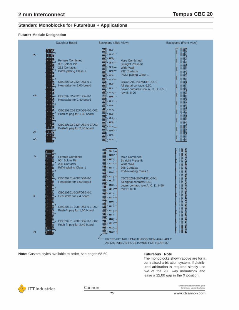
Dimensions are shown mm (inch)Dimensions subject to change
www.ittcannon.com70
Tempus CBC 20
Daughter Board Backplane (Side View) Backplane (Front View)
PRESS-FIT TAIL LENGTH/POSITION AVAILABLEAS DICTATED BY CUSTOMER FOR REAR I/O
Male CombinedStraight Press-fitWide Wall232 ContactsPd/NI-plating Class 1
CBC20Z02-232WDP1-57-1All signal contacts 6,50,power contacts: row A, C, D: 6,50,row B: 8,00
Male CombinedStraight Press-fitWide Wall208 ContactsPd/Ni-plating Class 1
CBC20Z01-208WDP1-57-1All signal contacts 6,50,power contact: row A, C, D: 6,50row B: 8,00
Female Combined90° Solder Pin232 ContactsPd/Ni-plating Class 1
CBC20Z02-232FDS1-0-1Heatstake for 1,60 board
CBC20Z02-232FDS2-0-1Heatstake for 2,40 board
CBC20Z02-232FDS1-0-1-002Push-fit peg for 1,60 board
CBC20Z02-232FDS2-0-1-002Push-fit peg for 2,40 board
Female Combined90° Solder Pin208 ContactsPd/Ni-plating Class 1
CBC20Z01-208FDS1-0-1Heatstake for 1,60 board
CBC20Z01-208FDS2-0-1Heatstake for 2,4 board
CBC20Z01-208FDS1-0-1-002Push-fit peg for 1,60 board
CBC20Z01-208FDS2-0-1-002Push-fit peg for 2,40 board
Futurebus+ NoteThe monoblocks shown above are for acentralised arbitration system. If distrib-uted arbitration is required simply usetwo of the 208 way monoblock andleave a 12,00 gap in the X position.
Note: Custom styles available to order, see pages 68-69
Future+ Module Designation
Standard Monoblocks for Futurebus + Applications
2 mm Interconnect

Dimensions are shown mm (inch)Dimensions subject to change
www.ittcannon.com71
Tempus CBC 20
How to use this table:1 find applicable backplane thickness 2 locate tail length of male module used 3 if resulting contact length (within assembled shroud) is indicatedon chart (i.e. a number between 5,00 and 8,00 mm), then 4 refer to recommended shroud base at top of page.Example: a 3,70 mm backplane with a 13,60 mm tail on the pressfit male module assembled will give a 6,50 mm contact on the rear of the back-plane when a 3,40 mm base shroud is used.
contact length at rear of backplanecontact length at rear of backplane
Shroud Base 7,20 mm
Tempus Tail Code U1 V2
Backplane Thickness Tail Length Tail Lengthmm (inch) 13,60 17,001,80 (.071) not compatible 8,00 (.316)
1,90 (.075) 7,90 (.312)
2,00 (.079) 7,80 (.308)
2,10 (.083) 7,70 (.304)
2,20 (.087) 7,60 (.300)
2,30 (.091) 7,50 (.296)
2,40 (.094) 7,40 (.292)
2,50 (.098) 7,30 (.288)
2,60 (.102) 7,20 (.284)
2,70 (.106) 7,10 (.280)
2,80 (.110) 7,00 (.276)
2,90 (.114) 6,90 (.272)
3,00 (.118) 6,80 (.268)
3,10 (.122) 6,70 (.264)
3,20 (.126) 6,60 (.260)
3,30 (.130) 6,50 (.256)
3,40 (.134) 6,40 (.252)
3,50 (.138) 6,30 (.248)
3,60 (.142) 6,20 (.244)
3,70 (.146) 6,10 (.240)
3,80 (.150) 6,00 (.236)
3,90 (.154) 5,90 (.232)
4,00 (.157) 5,80 (.228)
4,10 (.161) 5,70 (.224)
4,20 (.165) 5,60 (.220)
4,30 (.169) 5,50 (.216)
4,40 (.173) 5,40 (.212)
4,50 (.177) 5,30 (.208)
4,60 (.181) 5,20 (.204)
4,70 (.185) 5,10 (.200)
4,80 (.189) 5,00 (.196)
4,90 (.193)
5,00 (.197)
5,10 (.201)
5,20 (.205)
5,60 (.220)
5,70 (.224)
5,80 (.228)
5,90 (.232)
6,00 (.236)
6,10 (.240)
6,20 (.244)
6,30 (.248)
6,40 (.252)
6,50 (.256)
6,60 (.260)
Shroud Base 3,40 mm
Tempus Tail Code U1 V2
Backplane Thickness Tail Length Tail Lengthmm (inch) 13,60 17,001,80 (.071)
1,90 (.075)
2,00 (.079)
2,10 (.083)
2,20 (.087) 8,00 (.316)
2,30 (.091) 7,90 (.312)
2,40 (.094) 7,80 (.308)
2,50 (.098) 7,70 (.304)
2,60 (.102) 7,60 (.300)
2,70 (.106) 7,50 (.296)
2,80 (.110) 7,40 (.292)
2,90 (.114) 7,30 (.288)
3,00 (.118) 7,20 (.284)
3,10 (.122) 7,10 (.280)
3,20 (.126) 7,00 (.276)
3,30 (.130) 6,90 (.272)
3,40 (.134) 6,80 (.268)
3,50 (.138) 6,70 (.264)
3,60 (.142) 6,60 (.260)
3,70 (.146) 6,50 (.256)
3,80 (.150) 6,40 (252)
3,90 (.154) 6,30 (.248)
4,00 (.157) 6,20 (.244)
4,10 (.161) 6,10 (.240)
4,20 (.165) 6,00 (.236)
4,30 (.169) 5,90 (.232)
4,40 (.173) 5,80 (.228)
4,50 (.177) 5,70 (.224)
4,60 (.181) 5,60 (.220)
4,70 (.185) 5,50 (.216)
4,80 (.189) 5,40 (.212)
4,90 (.193) 5,30 (.208)
5,00 (.197) 5,20 (.205)
5,10 (.201) 5,10 (.201)
5,20 (.205) 5,00 (.197)
5,60 (.220) 8,00 (.316)
5,70 (.224) 7,90 (.312)
5,80 (.228) 7,80 (.308)
5,90 (.232) 7,70 (.304)
6,00 (.236) 7,60 (.300)
6,10 (.240) 7,50 (.296)
6,20 (.244) 7,40 (.292)
6,30 (.248) 7,30 (.288)
6,40 (.252) 7,20 (.284)
6,50 (.256) 7,10 (.280)
6,60 (.260) 7,00 (.276)
Design Notes Shroud / Tail Calculation
2 mm Interconnect
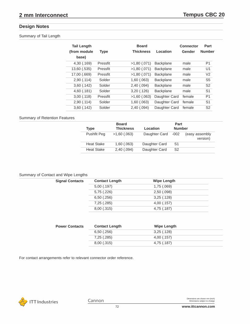
Dimensions are shown mm (inch)Dimensions subject to change
www.ittcannon.com72
Tempus CBC 20
Part
NumberConnector
GenderLocation
Board
ThicknessTypeTail Length
(from module
base)
For contact arrangements refer to relevant connector order reference.
Power Contacts Contact Length Wipe Length
6,50 (.256) 3,25 (.128)
7,25 (.285) 4,00 (.157)
8,00 (.315) 4,75 (.187)
Signal Contacts
Summary of Contact and Wipe Lengths
Contact Length Wipe Length
5,00 (.197) 1,75 (.069)
5,75 (.226) 2,50 (.098)
6,50 (.256) 3,25 (.128)
7,25 (.285) 4,00 (.157)
8,00 (.315) 4,75 (.187)
Summary of Retention Features
Board PartType Thickness Location Number
Pushfit Peg >1,60 (.063) Daughter Card -002 (easy assembly version)
Heat Stake 1,60 (.063) Daughter Card S1
Heat Stake 2,40 (.094) Daughter Card S2
Summary of Tail Length
4,30 (.169) Pressfit >1,80 (.071) Backplane male P1
13,60 (.535) Pressfit >1,80 (.071) Backplane male U1
17,00 (.669) Pressfit >1,80 (.071) Backplane male V2
2,90 (.114) Solder 1,60 (.063) Backplane male S5
3,60 (.142) Solder 2,40 (.094) Backplane male S2
4,60 (.181) Solder 3,20 (.126) Backplane male S1
3,00 (.118) Pressfit >1,60 (.063) Daughter Card female P1
2,90 (.114) Solder 1,60 (.063) Daughter Card female S1
3,60 (.142) Solder 2,40 (.094) Daughter Card female S2
Design Notes
2 mm Interconnect

Dimensions are shown mm (inch)Dimensions subject to change
www.ittcannon.com73
Tempus CBC 20
Solder
Termination Plated Through Drilled Hole Copper Tin
Hole Diameter (A) Diameter (D) Plating (B) Plating (C)0,65 - 0,77 0,78 - 0,83
(.025 - .031) (.031 - .033)
25 - 50 µm 5 - 15 µm(.001 - .002) (.0002 - .0006)
0,50 - 0,80 0,68 - 0,73(.020 - .031) (.027 - .029)
Pressfit
Design Notes
2 mm Interconnect

Dimensions are shown mm (inch)Dimensions subject to change
www.ittcannon.com74
Tempus CBC 20
IEC 61076-4-104 Connector
EIA is64 Connector
CECC draft 75101-810 Connector
IEEE 1301 Metric Equipment Practice
IEEE 1301.1 Equipment Practice using 2,00 Connector
IEC 917 Metric Modular Order
IEEE 896 Futerbus+
IEEE 1596 Scalable Coherent Interface
IEC International Electrotechnical Commission
EIA Electronic Industries Association
IEEE Institute of Electrical and Electronics Engineers
CECC CENELEC Electronic Components Committee
CENELEC European Committee for Electrotechnikcal Standardization
TEMPUS related specifications
Design Notes
2 mm Interconnect

Dimensions are shown mm (inch)Dimensions subject to change
www.ittcannon.com75
Tempus CBC 20
Tool Description Purpose Page
Backplane Assembly
Backplane Press, Fixed Tool Type Press male modules into backplane 76
Insertion Tooling, Fixed Tool Type Press male modules into backplane 77
Plug-in Circuit Board Assembly
Pushfit Press (Small Press) Press board mounted pushfit-peg modules onto plug-in circuit board 80
Pushfit-peg Hand Tool Press board mounted pushfit-peg modules onto plug-in circuit board 83
Shroud Assembly
Shroud Hand Tool Press shrouds onto rear of backplane 81
Shroud Press Tool Press shrouds onto rear of backplane 81
Backplane Repair
Signal Contact Repair Tool Remove and replace signal contact on the backplane 82
Power Contact Repair Tool Remove and replace power contact on the backplane 82
Cable Assembly
Cable Assembly Tool Terminate cable into i.d.c. cable connector terminals 83
The TEMPUS Connector System is fully supported by a full range of application toolingfor prototype to mass-production volumes.
Application Tool Overiew
2 mm Interconnect

Dimensions are shown mm (inch)Dimensions subject to change
www.ittcannon.com76
Tempus CBC 20
Backplane Press(Fixed Tool Type)
A pneumatically powered press for assembling male press-fit modules into a backplane/motherboardwhen used in conjunction with insertion tooling (Fixed Tool type)
Part Number Description
CPP-60-250 Backplane Press, pneumatic assisted
CT 120 090-62 PCB Control - thickness meter, 110/220 VAC, with movable support
CT 120 090-61 PCB Control - pressure force meter, 110 / 220 VAC
• Easy and fast tool change• Fine adjustment with measuring clock
Features
Backplane Assembly
Maximum Backplane Size
Press Capacity
Height
Width
Depth
Weight
Technical Data
Width 500,00 x 1200,00 (19,700 x 47,240) long
60 KN / 6 bar
900,00 (35.400)
1400,00 (55.100)
750,00 (29.500)
20 kg (551 lbs)
2 mm Interconnect

Dimensions are shown mm (inch)Dimensions subject to change
www.ittcannon.com77
Tempus CBC 20
Support Block Holder(for use with Backplane-Press Fixed Tool Type)Order reference CT121586-240
Press Block Holder
These tools may also be used withavailable fixed tool type press with asuitable adaptor. Please consultCannon for interface dimensions.
Note:Press blocks, support blocks as well as spacer have to be ordered separately
• Male Pressfit Connectors to the backplane
• Male Right-angle Connectors to the plug-in board
• Female Pressfit Connectors to the plug-in board
The Cannon basic press CPP-60-250is used with the following tools to assemble:
Insertion Tools (Fixed Tool Type)
If a cross slot or a quick change head is available in the pressbear, the Quick change part CT317-8661-053 can be usedreplacing part CT121586-297
Backplane Assembly, 4 Row
2 mm Interconnect
CT317-8661-053
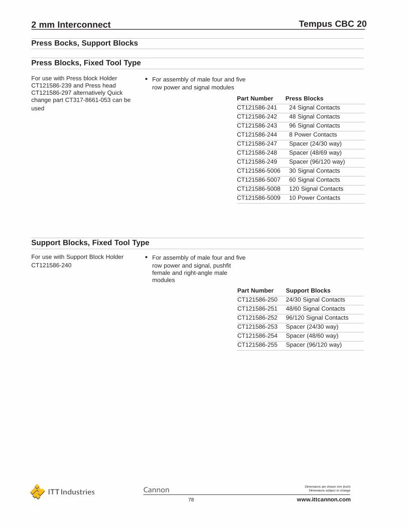
Dimensions are shown mm (inch)Dimensions subject to change
www.ittcannon.com78
Tempus CBC 20
• For assembly of male four and five row power and signal, pushfit female and right-angle male modules
Part Number Support Blocks
CT121586-250 24/30 Signal Contacts
CT121586-251 48/60 Signal Contacts
CT121586-252 96/120 Signal Contacts
CT121586-253 Spacer (24/30 way)
CT121586-254 Spacer (48/60 way)
CT121586-255 Spacer (96/120 way)
For use with Support Block Holder CT121586-240
Support Blocks, Fixed Tool Type
Part Number Press Blocks
CT121586-241 24 Signal Contacts
CT121586-242 48 Signal Contacts
CT121586-243 96 Signal Contacts
CT121586-244 8 Power Contacts
CT121586-247 Spacer (24/30 way)
CT121586-248 Spacer (48/69 way)
CT121586-249 Spacer (96/120 way)
CT121586-5006 30 Signal Contacts
CT121586-5007 60 Signal Contacts
CT121586-5008 120 Signal Contacts
CT121586-5009 10 Power Contacts
Press Bocks, Support Blocks
• For assembly of male four and five row power and signal modules
For use with Press block Holder CT121586-239 and Press head CT121586-297 alternatively Quickchange part CT317-8661-053 can beused
Press Blocks, Fixed Tool Type
2 mm Interconnect

Dimensions are shown mm (inch)Dimensions subject to change
www.ittcannon.com79
Tempus CBC 20
The Cannon Basic Press CPP-60-250 is usedwith the following tools to assemble:
- Male Right-Angle Pressfit Modules- Female Right-Angle Pressfit Modules
Male Right-Angle Connectors withpushfit retention and pressfit tailsto the plug-in board.
Female Connectors with pushfitretention and pressfit tails to the plug-in board.
Support block holder with support blocks and Quick changepart CT317-8661-053. See page 77
Note:Fixing head and press-head, stamp as well assupport block and support block holder have tobe orderd separately
Malepushfit retention
pressfit tail
24 board support
48 board support
96 board support
CT121586-5019
CT121586-5020
CT121586-5021
Part Number Connector Pushfit Block
Femalepushfit retention
pressfit tail
24/30 board support
48/60 board support
96/120 board support
CT121586-302
CT121586-303
CT121586-304
Part Number Connector Pushfit Block
Male Right-Angle Connector, Female Connectors
2 mm Interconnect

Dimensions are shown mm (inch)Dimensions subject to change
www.ittcannon.com80
Tempus CBC 20
Order Reference for Support and Press Head Male Right-AngledCHP-CBC20-Pushfit-M
Order Reference Basic PressCHP-420
Order Reference for Support and Press Jead FemaleCHP-CBC20-Pushfit-F
A hand operated tool for assembling TEMPUSmale and female modules with pushfit peg.
• Consult Cannon for non-standard orspecial board size applications
• Fix up to 12 modules in a single operation
• Quick change adaptor kits for plug-in board mounted male and female modules
• Min/max board dimensions
Features
Pushfit Press-in Tool
2 mm Interconnect

Dimensions are shown mm (inch)Dimensions subject to change
www.ittcannon.com81
Tempus CBC 20
CT121586-295CT121586-296
CT121586-305
CT121586-239
Shroud Hand Tool Shroud Press Tool
If a cross slot or a quick change head is available in the press bear, the Quickchange part CT317-8661-053 can be used replacing part CT121586-297
Shroud Press Tool, to assemble up to 5x12 mm shroud, for use with CPP-60-250:
Part Number Description
CT121586-297 Press head with 90° rotation
CT121586-298 Press stamp
CT121586-305 Support base
Shrouds may be pressfit assembledinto male tails on the rear of the back-plane using either simple hand tools orpress assisted tools.
Part Number Description
CT121586-295 Shroud Hand Tool, 1 Module
CT121586-296 Shroud Hand Tool, 2 Modules
• Press tool head rotates to suit boardlayout
• Low or high volume tools
• Simple fast assembly of TEMPUS shrouds to backplane
Features
Shroud Assembly
2 mm Interconnect
CT317-8661-053

Dimensions are shown mm (inch)Dimensions subject to change
www.ittcannon.com82
Tempus CBC 20
Insertion/Extraction Tool for PowerContacts
Insertion/Extraction Tool for SignalContacts
Backplane Repair
Part Number Description
CIET-CBC20HV Power Contact Repair Tool
• A hand tool to remove and replace single power blade contacts into male modules when assembled intoa backplane.
Part Number Description
CIET-CBC20 Signal Contact Repair Tool
• A hand tool to remove and replace single signal contacts into male modules when assembled into a backplane.
Features
2 mm Interconnect

Dimensions are shown mm (inch)Dimensions subject to change
www.ittcannon.com83
Tempus CBC 20
Cannon has a policy of expanding the TEMPUS system inaccordance with customer wishes in addition to specification.
Due to the flexible manufacturing methods employed many ofthese developments can be incorporated into monoblocks.
...at the development or prototypestage now
• Fibre optic systems
• High speed transmission up to 2, 4 Gigabit / second
• Reverse system
Developments
Part Number Description
995-2000-064 Pushfit-peg Hand Tool CTHT-200
TEMPUS Pushfit-peg Hand Tool• For hand assembly of to six female
modules with pushfit-peg onto a plug-in circuit board.
Part Number Description
CT121586-5010 TEMPUS Cable Connector IDC Tool
TEMPUS IDC Termination Tool• For IDC termination and crimp
retention of cable into the TEMPUS 24 position and 48 position cable connectors.
Cable Connector Assembly
2 mm Interconnect

THIS NOTE MUST BE READ IN CON-JUNCTION WITH THE PRODUCT DATASHEET/CATALOG. FAILURE TOOBSERVE THE ADVICE IN THISINFORMATION SHEET AND THEOPERATING CONDITIONS SPECIFIEDIN THE PRODUCT DATA SHEET/ CATA-LOG COULD RESULT IN HAZARDOUSSITUATIONS.
1. MATERIAL CONTENT AND PHYSI-CAL FORMElectrical connectors do not usually con-tain hazardous materials. They containconducting and non-conducting materialsand can be divided into two groups.a) Printed circuit types and low cost audiotypes which employ all plastic insulatorsand casings.b) Rugged, Fire Barrier and HighReliability types with metal casings andeither natural rubber, synthetic rubber,plastic or glass insulating materials.Contact materials vary with type of con-nector and also application and are usu-ally manufactured from either: Copper,copper alloys, nickel, alumel, chromel orsteel. In special applications, other alloysmay be specified.
2. FIRE CHARACTERISTICS AND ELEC-TRIC SHOCK HAZARDThere is no fire hazard when the connec-tor is correctly wired and used within thespecified parameters. Incorrect wiring orassembly of the connector or carelessuse of metal tools or conductive fluids, ortransit damage to any of the componentparts may cause electric shock or burns.Live circuits must not be broken by sepa-rating mated connectors as this maycause arcing, ionization and burning.Heat dissipation is greater at maximumresistance in a circuit. Hot spots mayoccur when resistance is raised locally bydamage, e.g. cracked or deformed con-tacts, broken strands of wire. Local over-heating may also result from the use ofthe incorrect application tools or frompoor quality soldering or slack screw ter-minals. Overheating may occur if the rat-ings in the product Data Sheet/Catalogare exceeded and can cause breakdownof insulation and hence electric shock. Ifheating is allowed to continue it intensi-fies by further increasing the local resist-ance through loss of temper of springcontacts, formation of oxide film on con-tacts and wires and leakage currentsthrough carbonization of insulation andtracking paths. Fire can then result in thepresence of combustible materials andthis may release noxious fumes.Overheating may not be visually appar-ent. Burns may result from touching over-heated components.
3. HANDLINGCare must be taken to avoid damage to any component parts of electrical con-nectors during installation and use.Although there are normally no sharpedges, care must be taken when handlingcertain components to avoid injury to fin-gers. Electrical connectors may be dam-aged in transit to the customers, anddamage may result in creation of haz-ards. Products should therefore be exam-ined prior to installation/use and rejectedif found to be damaged.
4. DISPOSALIncineration of certain materials mayrelease noxious or even toxic fumes.
5. APPLICATIONConnectors with exposed contacts shouldnot be selected for use on the currentsupply side of an electrical circuit,because an electric shock could resultfrom touching exposed contacts on anunmated connector. Voltages in excess of30 V ac or 42.5 V dc are potentially haz-ardous and care should be taken toensure that such voltages cannot betransmitted in any way to exposed metalparts of the connector body. The connec-tor and wiring should be checked, beforemaking live, to have no damage to metalparts or insulators, no solder blobs, loosestrands, conducting lubricants, swarf, orany other undesired conducting particles.Circuit resistance and continuity checkshould be made to make certain thatthere are no high resistance joints or spu-rious conducting paths. Always use thecorrect application tools as specified inthe Data Sheet/Catalog. Do not permituntrained personnel to wire, assemble ortamper with connectors. For operationvoltage please see appropriate nationalregulations.
IMPORTANT GENERAL INFORMATION(i) Air and creepage paths/Operating volt-age. The admissible operating voltagesdepend on the individual applications andthe valid national and other applicablesafety regulations.For this reason the air and creepage pathdata are only reference values. Observereduction of air and creepage paths dueto PC board and/or harnessing.
(ii) TemperatureAll information given are temperature lim-its. The operation temperature dependson the individual application.
(iii) Other important informationCannon continuously endeavors toimprove their products. Therefore,Cannon products may deviate from thedescription, technical data and shape asshown in this catalog and data sheets.
“Engineered for life” is a registered trade-mark of ITT Industries, ©2003. All othertrademarks or registered trademarks areproperty of their respective owners. Alldata subject to change without notice.
Product WarrantyITT Cannon, a Division of ITTIndustries, Inc. manufactures the high-est quality products available in themarketplace; however these productsare intended to be used in accordancewith the specifications in this publica-tion. Any use or application that devi-ates from the stated operating specifi-cations is not recommended and maybe unsafe. No information and datacontained in this publication shall beconstrued to create any liability on thepart of Cannon. Any new issue of thispublication shall automatically invali-date and supersede any and all previ-ous issues. A limited warranty appliesto Cannon products. Except for obliga-tions assumed by Cannon under thiswarranty, Cannon shall not be liable forany loss, damage, cost of repairs, inci-dental or consequential damages ofany kind, whether or not based onexpress or implied warranty, contract,negligence or strict liability arising inconnection with the design, manufac-ture, sale, use or repair of the products.Product availability, prices and deliverydates are exclusively subject to ourrespective order confirmation form; thesame applies to orders based ondevelopment samples delivered. Thispublication is not to be construed as anoffer. It is intended merely as an invita-tion to make an offer. By this publica-tion, Cannon does not assume respon-sibility or any liability for any patentinfringements or other rights of thirdparties which may result from its use.Reprinting this publication is generallypermitted, indicating the source.However, Cannon's prior consent mustbe obtained in all cases.
Dimensions are shown mm (inch)Dimensions subject to change
www.ittcannon.com84
Product Safety Information