ten years of innovation in the application of piled
TRANSCRIPT

Geosynthetics 2013 April 1-4, Long Beach, California
Ten Years of Innovation in the Application of Piled Embankments in the Netherlands A.E.C. van der Stoel, PhD., University of Twente / CRUX Engineering Netherlands, [email protected] ABSTRACT This paper describes the construction and some general aspects of the design and execution of several Load Transfer Platforms (LTPs) or piled embankments in the Netherlands over the past 10 years. In this period extensive innovations were carried out in both design and execution, resulting in a new design guideline and innovative applications. Because of the particularly poor soil circumstances, many specific challenges were encountered during construction of piles and geogrids. The paper first briefly outlines the major design rules in Dutch Guideline CUR226 after which an extensive overview is given of the major characteristics of various executed projects for road and rail constructions. The paper concludes with two completely new and innovative applications: one for a cemetery (currently being realized) and one for the crane platforms of the biggest on-shore wind farm in the Netherlands (>7,5MW, >198m tip). 1. INTRODUCTION Because of an emphasis on reducing construction time, lateral movements near existing structures (bridges, aqueducts) and reducing the disturbance to the surrounding area during the construction of embankments, several Load Transfer Platforms (LTPs) on piles or Piled Embankments (PEs) have been constructed in the Netherlands in the past 10 years. Piled embankments generally consist of a large number of piles, installed at a small spacing, overlain by geogrids in a platform of material with a high friction, the Load Transfer Platform (LTP). The general principle is illustrated in Figure 1: after applying a working platform of sand (1), the piles (2) and steel pile reinforcement (3) are installed, on which a pile cap (4) is placed (prefab) or casted. On top a mattress (5) consisting of geogrids and granular material is constructed. Finally, on top of this the embankment and (rail)road can be constructed without (piles in bearing layer) or with limited settlements (friction piles, not shown in Figure 1) any settlements occurring.
Figure 1: Principle of piled embankment installation 2. SOIL CONDITIONS IN THE NETHERLANDS To sketch the typical circumstance in which piled embankments are applied in the Netherlands, two typical soil profiles are outlined. Most typical for the soil conditions is that the top meters consist of soft soils with a high groundwater table. In Figure 2 (left, Amsterdam) a soil profile, that is typical for the ground conditions in the western part of the Netherlands is shown. The top layer of the first meters below surface level consists of Anthropogenic sand. Below this top layer the
1154

Holocene deposits are found until a depth of about 10-15 m below surface level. The Holocene formation can be divided (from top to bottom) into peat (Hollandveen), clay (Oude Zeeklei), silty sand (Wadzand), clay (Hydrobiaklei) and peat (Basisveen). The soft Holocene has been deposited on top of the stiff Pleistocene sands which are sometimes divided by an intermediate silty, clayey sand layer (Allerod). The phreatic water level is found about 0.4 m to 1.5m below surface level. The artesian water level in the Pleistocene sand layers usually lie 2 m below the phreatic water level.
Figure 2: Characteristic soil profile for western part (left) and northern part (right) of the Netherlands For the northern part of the Netherlands, the soil conditions are comparable with the western part of the Netherlands, only the Holocene layers are generally much more loamy, see Figure 2 (right, Leeuwarden). The phreatic water level is found about 1.0 m to 2.5m below surface level. For the central and eastern part of the Netherlands, the soil consists of mainly medium dense to dense Pleistocene sand layers, locally overtopped by some Holocene clay or silt layers. The application of piled embankments for these profiles is generally less interesting compared to convention settlement reducing solutions. 3. MODELING PILED EMBANKMENTS 3.1 Introduction to CUR226 In 2010, the Dutch Design Guideline for the design of piled embankments CUR 226 (2010), has been introduced. The outlines of this Design Guideline are given by Van Eekelen et al (2010). The choices made within the Dutch Design Guideline are based on comparisons with and analyses of several field tests, finite element calculations, parameter studies, and work of several authors. The BS8006 (1995 and 2010) and the EBGEO (2010) have been discussed in great detail and the decision was made to adopt the design method of Zaeske (2010) / EBGEO. The safety philosophy and the constraints of the EBGEO for the applicability of the design rules have been adapted for the Dutch situation. In the first stage of the design of a piled embankment, the efforts can usually be limited to calculations for the grids and the bearing capacity of the piles. Lateral loads can however cause relatively large bending moments in the piles, and because the steel pile-reinforcement significantly contributes to the total costs, the determination of displacements, lateral forces and bending moments plays an important role in the design process. In the next paragraphs the design stages of the CUR 226 will be explained. 3.2 Analytical Grid Calculation In the design of the geosynthetic reinforcement, several calculation steps are distinguished. After the material properties en load- and material factors are determined, all loads are converted to an uniformly distributed load and the force distribution within the piled embankment (piles, reinforcement & subsoil) is determined. The line loads that result from this are translated into a strain and membrane tensile force and the spreading perpendicular to the (rail)road axis is included. Because the tensile force depends on the tensile stiffness of the grid, this calculation is an iterative process.
1155

In the past years much research has been performed by Van Eekelen et al. (2012a, 2012b, 2012c), which will probably be incorporated in a revised version of the CUR226 guideline. 3.3 Pile Calculation The vertical bearing capacity of the piles is determined analytically using the Dutch design guidelines Eurocode 7 - NEN 9997-1 (2012). The LTP can be either considered as a Settlement Free Construction (SFC+ settlements < 3cm), where the end-bearing piles transfer the full load to the bearing layers, or as Settlement Reduction Construction (SRC), where a limited settlement of the LTP is accepted and part of the load is transferred to the subsoil between the pile(cap)s and the rest is transferred to (friction) piles. 3.4 Bending Moments in Piles A major part of the design of the LTP is formed by the determination of the bending moments is the piles, caused by for example vehicle loads or asymmetry of the embankment. Because of the complicated deformation behavior of the LTP, this can generally not be done analytically. Therefore, Finite Element Method (FEM) calculations are used to calculate pile moments and deformations. The FEM computer program PLAXIS is very suitable for modeling LTPs (Slaats & Van der Stoel, 2009 & Van der Stoel et al 2007b). Based on the SI the soil profile for the model geometry is determined. For modeling the soil layers the Hardening Soil or Soft Soil Creep model are most appropriate, because they are capable to describe reduction of stiffness as well as irreversible deviator strains due to deviatoric stress. In order to get appropriate parameters for the model, samples have to be taken from the (soft soil) layers that are considered to be most important regarding deformations. Besides determining the volumetric weight (γ), triaxial tests and oedometer tests should be performed for determining stiffness parameters (E50, Eoed) and strength parameters (c’, φ’). Although complex geometries justify a 3D approach, 2D FEM is still preferred because of lower model complexity and limited calculation time. The validity of the CUR226 approach has been verified Houten case (Table 1, #22), using Plaxis 3D Tunnel and Plaxis 2D v9 respectively, see also Figure 3. The bending moments in the piles have been compared for various cases with different traffic loads and soil support, from which the conclusion could be drawn that the bending moments generally occur at the same locations and the extreme bending moments per pile do not differ significantly. Therefore it was concluded that 2D calculations assess the maximum occurring bending moment quite accurately and some reserve should be made when using a 2D model to determine the exact location of the extreme bending moments.
Figure 3: Example of 3D (left) and 2D model (right) based on CUR 226 Recently the calculations of the pile reinforcement and grids of the piled embankment of the highway A12 in Woerden (Table 1, #23), designed using PLAXIS 2D v9, was compared with PLAXIS 3DTunnel (2.4) and PLAXIS 3D 2011 calculations by Oskam (2012). The results, see Figure 4, confirm the CUR 226 findings.
1156
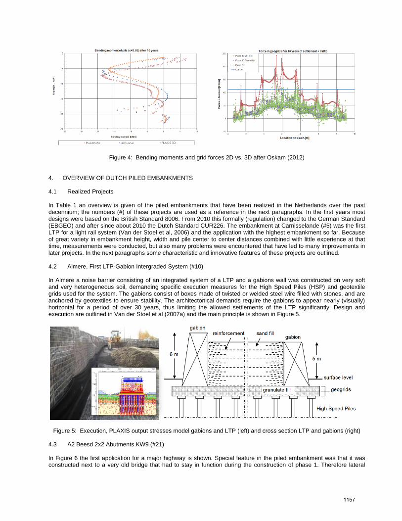
Figure 4: Bending moments and grid forces 2D vs. 3D after Oskam (2012) 4. OVERVIEW OF DUTCH PILED EMBANKMENTS 4.1 Realized Projects In Table 1 an overview is given of the piled embankments that have been realized in the Netherlands over the past decennium; the numbers (#) of these projects are used as a reference in the next paragraphs. In the first years most designs were based on the British Standard 8006. From 2010 this formally (regulation) changed to the German Standard (EBGEO) and after since about 2010 the Dutch Standard CUR226. The embankment at Carnisselande (#5) was the first LTP for a light rail system (Van der Stoel et al, 2006) and the application with the highest embankment so far. Because of great variety in embankment height, width and pile center to center distances combined with little experience at that time, measurements were conducted, but also many problems were encountered that have led to many improvements in later projects. In the next paragraphs some characteristic and innovative features of these projects are outlined. 4.2 Almere, First LTP-Gabion Intergraded System (#10) In Almere a noise barrier consisting of an integrated system of a LTP and a gabions wall was constructed on very soft and very heterogeneous soil, demanding specific execution measures for the High Speed Piles (HSP) and geotextile grids used for the system. The gabions consist of boxes made of twisted or welded steel wire filled with stones, and are anchored by geotextiles to ensure stability. The architectonical demands require the gabions to appear nearly (visually) horizontal for a period of over 30 years, thus limiting the allowed settlements of the LTP significantly. Design and execution are outlined in Van der Stoel et al (2007a) and the main principle is shown in Figure 5.
Figure 5: Execution, PLAXIS output stresses model gabions and LTP (left) and cross section LTP and gabions (right) 4.3 A2 Beesd 2x2 Abutments KW9 (#21) In Figure 6 the first application for a major highway is shown. Special feature in the piled embankment was that it was constructed next to a very old bridge that had to stay in function during the construction of phase 1. Therefore lateral
1157

displacements were a big issue and no consolidation time was available. Thus, the high abutment foundation was constructed before construction of the LTP. When the embankment and new bridge were completed, the old bridge was demolished and at this location also a piled embankment was constructed.
Figure 6: Existing bridge (old situation, left), LTP, sheet pile and abutment foundation (right)
1158
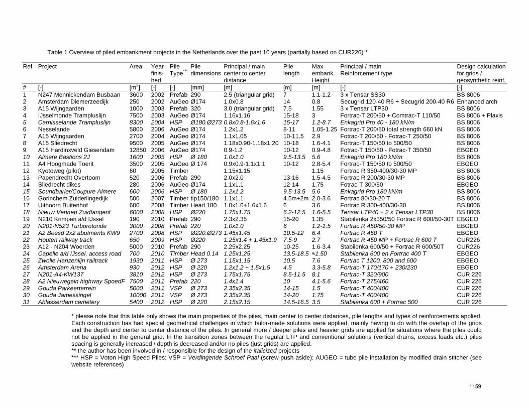
Table 1 Overview of piled embankment projects in the Netherlands over the past 10 years (partially based on CUR226) *
Ref Project Area Year finis-hed
Pile Type
*** Pile dimensions
Principal / main center to center distance
Pile length
Max embank. Height
Principal / main Reinforcement type
Design calculation for grids / geosynthetic reinf.
# [-] [m2] [-] [-] [mm] [m] [m] [m] [-] [-]
1 N247 Monnickendam Busbaan 3600 2002 Prefab 290 2.5 (triangular grid) 7 1.1-1.2 3 x Tensar SS30 BS 8006 2 Amsterdam Diemerzeedijk 250 2002 AuGeo Ø174 1.0x0.8 14 0.8 Secugrid 120-40 R6 + Secugrid 200-40 R6 Enhanced arch 3 A15 Wijngaarden 1000 2003 Prefab 320 3.0 (triangular grid) 7.5 1.55 3 x Tensar LTP30 BS 8006 4 IJsselmonde Trampluslijn 7500 2003 AuGeo Ø174 1.16x1.16 15-18 3 Fortrac-T 200/50 + Comtrac-T 110/50 BS 8006 + Plaxis 5 Carnisselande Trampluslijn 8300 2004 HSP Ø180.Ø273 0.8x0.8-1.6x1.6 15-17 1.2-8.7 Enkagrid Pro 40 - 180 kN/m BS 8006 6 Nesselande 5800 2006 AuGeo Ø174 1.2x1.2 8-11 1.05-1.25 Fortrac-T 200/50 total strength 660 kN BS 8006 7 A15 Wijngaarden 2700 2004 AuGeo Ø174 1.1x1.05 10-11.5 2.9 Fotrac-T 200/50 - Fotrac-T 250/50 BS 8006 8 A15 Sliedrecht 9500 2005 AuGeo Ø174 1.18x0.90-1.18x1.20 10-18 1.6-4.1 Fortrac-T 150/50 to 500/50 BS 8006 9 A15 Hardinxveld Giesendam 12850 2006 AuGeo Ø174 0.9-1.2 10-12 0.9-4.8 Fotrac-T 150/50 - Fotrac-T 350/50 EBGEO 10 Almere Bastions 2J 1600 2005 HSP Ø 180 1.0x1.0 9.5-13.5 5.6 Enkagrid Pro 180 kN/m BS 8006 11 A4 Hoogmade Toerit 3500 2005 AuGeo Ø 174 0.9x0.9-1.1x1.1 10-12 2.8-5.4 Fortrac-T 150/50 to 500/50 EBGEO 12 Kyotoweg (pilot) 60 2005 Timber 1.15x1.15 1.15 Fortrac R 350-400/30-30 MP BS 8006 13 Papendrecht Overtoom 520 2006 Prefab 290 2.0x2.0 13-16 1.5-4.5 Fortrac R 200/30-30 MP BS 8006 14 Sliedrecht dikes 280 2006 AuGeo Ø174 1.1x1.1 12-14 1.75 Fotrac-T 300/50 EBGEO 15 Soundbarier/Coupure Almere 600 2006 HSP Ø 180 1.2x1.2 9.5-13.5 5.6 Enkagrid Pro 180 kN/m BS 8006 16 Gorinchem Zuiderlingedijk 500 2007 Timber tip150/180 1.1x1.1 4.5m+2m 2.0-3.6 Fortrac 80/30-20 T BS 8006 17 Uithoorn Buitenhof 600 2008 Timber Head 180 1.0x1.0+1.6x1.6 6 3.6 Fortrac R 300-400/30-30 BS 8006 18 Nieuw Vennep Zuidtangent 6000 2008 HSP Ø220 1.75x1.75 6.2-12.5 1.6-5.5 Tensar LTP40 + 2 x Tensar LTP30 BS 8006 19 N210 Krimpen a/d IJssel 190 2010 Prefab 290 2.3x2.35 15-20 1.35 Stabilenka 2x350/50 Fortrac R 600/50-30T EBGEO 20 N201-N523 Turborotonde 3000 2008 Prefab 220 1.0x1.0 6 1.2-1.5 Fortrac R 450/50-30 MP EBGEO 21 A2 Beesd 2x2 abutments KW9 2700 2008 HSP Ø220.Ø273 1.45x1.45 10.5-12 6.4 Fortrac R 450 T EBGEO 22 Houten railway track 650 2009 HSP Ø220 1.25x1.4 + 1.45x1.9 7.5-9 2.7 Fortrac R 450 MP + Fortrac R 600 T CUR226 23 A12 - N204 Woerden 5000 2010 Prefab 290 2.25x2.25 10-25 1.6-3.4 Stabilenka 600/50 + Fortrac R 600/50T CUR226 24 Capelle a/d IJssel, access road 700 2010 Timber Head 0.14 1.25x1.25 13.5-18.5 ≈1.50 Stabilenka 600 en Fortrac 400 T EBGEO 25 Zwolle Hanzenlijn railtrack 1930 2011 HSP Ø 273 1.15x1.15 10.5 7.6 Fortrac T 1200. 800 and 600 EBGEO 26 Amsterdam Arena 930 2012 HSP Ø 220 1.2x1.2 + 1.5x1.5 4.5 3.3-5.8 Fortrac-T 170/170 + 230/230 EBGEO 27 N201-A4-KW137 3810 2012 HSP Ø 273 1.75x1.75 8.5-11.5 8.1 Fortrac-T 320/900 CUR 226 28 A2 Nieuwegein highway SpoedF 7500 2011 Prefab 220 1.4x1.4 10 4.1-5.6 Fortrac-T 275/460 CUR 226 29 Gouda Parkeerterrein 5000 2011 VSP Ø 273 2.35x2.35 14-15 1.5 Fortrac-T 400/400 CUR 226 30 Gouda Jamessingel 10000 2011 VSP Ø 273 2.35x2.35 14-20 1.75 Fortrac-T 400/400 CUR 226 31 Ablasserdam cemetery 5400 2012 HSP Ø 220 2.15x2.15 14.5-16.5 3.5 Stabilenka 600 + Fortrac 500 CUR 226
* please note that this table only shows the main properties of the piles, main center to center distances, pile lengths and types of reinforcements applied. Each construction has had special geometrical challenges in which tailor-made solutions were applied, mainly having to do with the overlap of the grids and the depth and center to center distance of the piles. In general more / deeper piles and heavier grids are applied for situations where the piles could not be applied in the general grid. In the transition zones between the regular LTP and conventional solutions (vertical drains, excess loads etc.) piles spacing is generally increased / depth is decreased and/or no piles (just grids) are applied. ** the author has been involved in / responsible for the design of the italicized projects *** HSP = Voton High Speed Piles; VSP = Verdingende Schroef Paal (screw-push aside); AUGEO = tube pile installation by modified drain stitcher (see website references)
1159

4.4 Houten, First Railway Application and Special Transition Zone (#22) In Houten, the first LTP for a main railway system was applied (Van Duijnen et al, 2010 and Van der Stoel et al 2010). Because of the specific requirements that had to be met for the transition between a (rigid bridge) foundation on one side and a regular embankment on the other side, a LTP transition zone was applied, see Figure 7. After the regular LTP in zone 2, in zone 3A first the pile spacing was increased, after which in zone 3B this spacing was increased further and the length of the piles was reduced. Finally in zone 4 no piles were applied, thus creating a smooth transition.
Figure 7: Houten Plaxis input model LTP and wall (left) and construction LTP next to operational railroad (right) 4.5 Zwolle Hanzelijn, Rail Crossing and Integrated System (#25) Near Zwolle, the Hanzelijn, the new rail link between the central Randstad urbanization and the north of the Netherlands is constructed. Prior to constructing a railtunnel trough (see Figure 8), the surrounding area was partially preloaded with sand to limit the settlement caused by the fill alongside the tunnel. The need for a piled embankment for the railway lines around the intersection arises from the local geotechnical impact of connecting to the existing tunnel trough (Van der Stoel et al, 2012). The tunnel comprises a closed part with an open part at each end. The two lines cross at the closed part. The lateral loads on the walls of the open parts are relieved through the use of a reinforced soil construction for the fill (see Figure 9). The piled embankment at the intersection will help to reduce the horizontal soil pressure against the open trough and duct, and prevent excessive moments in the piles underneath the structure. This method also guarantees the stability of the reinforced soil construction. This solution, with high demands on differential settlements between the piled embankment and the rigid tunnel foundation, was the first application for a railway / tunnel crossing.
1160

Figure 8: Overview Hanzelijn crossing tunnel (left) and Plaxis model LTP and soil reinforcement (right)
Figure 9: Hanzelijn pile installation (left), bottom grid (middle) and layered soil reinforcement (right) 4.6 Gouda, Very Low Embankment, Road and Parking (#29 & #30) In Gouda, both a road and a large parking were constructed on very soft soil. Special circumstances were the possible presence of WWII explosives, so for the first time, vibration free screwed piles were used. To reduce the risk of hitting explosives during pile installation, high center to center distances were demanded. Combined with the very low embankment due to the necessary connection to existing roads, this led to the most ‘slender’ piled embankment system so far, see Figure 10. To be able to transfer the loads to the piles, relatively large pile caps had to be applied combined with a small excavation below water level before pile installation / construction.
1161
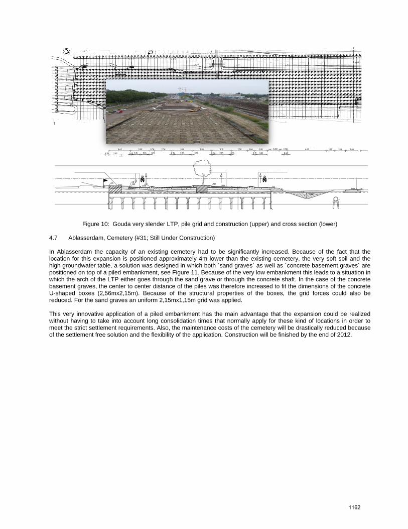
Figure 10: Gouda very slender LTP, pile grid and construction (upper) and cross section (lower) 4.7 Ablasserdam, Cemetery (#31; Still Under Construction) In Ablasserdam the capacity of an existing cemetery had to be significantly increased. Because of the fact that the location for this expansion is positioned approximately 4m lower than the existing cemetery, the very soft soil and the high groundwater table, a solution was designed in which both ´sand graves´ as well as ´concrete basement graves´ are positioned on top of a piled embankment, see Figure 11. Because of the very low embankment this leads to a situation in which the arch of the LTP either goes through the sand grave or through the concrete shaft. In the case of the concrete basement graves, the center to center distance of the piles was therefore increased to fit the dimensions of the concrete U-shaped boxes (2,56mx2,15m). Because of the structural properties of the boxes, the grid forces could also be reduced. For the sand graves an uniform 2,15mx1,15m grid was applied. This very innovative application of a piled embankment has the main advantage that the expansion could be realized without having to take into account long consolidation times that normally apply for these kind of locations in order to meet the strict settlement requirements. Also, the maintenance costs of the cemetery will be drastically reduced because of the settlement free solution and the flexibility of the application. Construction will be finished by the end of 2012.
1162

Figure 11: Two cross sections (1-1, upper & 5-5 lower) and plan view of cemetery with sand graces and tombs 4.8 Noordoostpolder, Wind Park (to Be Constructed Fall 2012/Spring 2013) A partnership of more than 100 agricultural entrepreneurs from the North East Polder and energy company RWE/Essent are about to construct the largest wind farm in the Netherlands (website). It will be located on-shore and near-shore along the dikes of the IJsselmeer. The estimated total investment comprises about 1 billion euros. The 86 wind turbines (>7,5MW, >198m tip) of Windpark Noordoostpolder will generate 1.4 billion kWh of clean sustainable electricity per year in 2015, enough to power more than 400,000 households every day. This makes the North East Polder one of the leading European regions in modern wind energy. In order to build the first 12 on-land wind turbines, a huge mobile crane is needed to place the generator on the tower. In order to build this crane, smaller (but still large) mobile cranes are needed. To position these cranes on the very soft soil and to be able to reach the needed positioning accuracy at hub height, settlement is not allowed at the platform. Therefore, piled embankments will be applied at each location, as shown in Figure 12. Because of the high load on the crane platform (260 kN/m2) and the surrounding platform (185 kN/m2), a HSP pile grid of 1,10x1,10m and 1,30x1,30m respectively will be used. The area of the platforms is 5000 m2 each, adding up to about 60.000m2 total, making it the largest application of a LTP in the Netherlands so far. Special attention is required for the interface between the foundation of the turbines themselves and the crane platform. For this, special FEM interaction calculations have been made, which will be published in near future.
1163

Figure 12: Two cross sections and plan view of wind mill construction LTP (and interaction with mill foundation) 5. CONCLUSION The application of piled embankments has taken a huge flight in the Netherlands in the past ten years. Because of the work conducted by the CUR committee, the publication of the CUR226 guidelines, the many research projects and the fast experience that has been gained in multiple applications, design and execution have been brought to a next level, in which innovative applications, as for the cemetery and wind turbines, are made possible. ACKNOWLEDGEMENTS The author greatly acknowledges the permission of CUR committee 226 on piled embankments, Heijmans, Dura Vermeer, Voorbij Funderingstechnieken / TBI Infra, Huesker Geosynthetics, Koninklijke Sjouke Dijkstra and RWE Essent to use multiple photos and figures in this paper.
1164

REFERENCES Duijnen, P.G. van, Eekelen, S.J.M. van, Stoel, A.E.C. van der, Monitoring of a Railway Piled Embankment, 2010,
Proceedings of 9th International Conference on Geosynthetics, Brazil, 2010, pp 1461-1464 van Eekelen, S.J.M., Jansen, H.L., Duijnen, P.G., van, De Kant, M., Dalen, J.H., van, Brugman, M.H.A., Stoel, A.E.C.,
van der, Peters, M.G.J.M., The Dutch design guideline for piled embankments, Proceedings of 9th International Conference on Geosynthetics, Brazil, 2010, pp 1911-1916
van Eekelen, S.J.M., Bezuijen, A., Lodder, H.J., van Tol, A.F., 2012a and 2012b. “Model experiments on piled embankments” Geotextiles and Geomembranes 32 part I 69-81+ Part II.”82-94
van Eekelen, S.J.M. and Bezuijen, A., 2012c, Dutch Research on basal reinforced piled embankments, Geotechniek Special, English edition, pp. 12-17
Oskam, E., Piled embankments in PLAXIS 2D, 3DTunnel and PLAXIS 3D 2011, Plaxis Bulletin Issue 31, March, 2012 Slaats, H and Stoel, A.E.C. van der, Validation of numerical model components of LTP by means of experimental data,
17th International Conference on Soil Mechanics & Geotechnical Engineering, Alexandria, Egypt, 5-9 October 2009 van der Stoel, A.E.C., De Lange, A.P., Bussert, F. & Meyer, N., Railway embankment on "high speed piles" - Design,
installation and monitoring, Eighth International Conference on Geosynthetics, September 2006, Yokohama Japan van der Stoel, A.E.C., Vink, D., Ravensbergen, R.W., De Hertog M., Design and execution of an integrated LTP and
gabions system, XIV European Conference on Soil Mechanics and Geotechnical Engineering. Madrid, 2007a van der Stoel, A.E.C., J.W. Dijkstra & H. Slaats, A comparative study on the design of LTP; XIV European Conference
on Soil Mechanics and Geotechnical Engineering, Madrid, 2007b van der Stoel, A.E.C., Brok, C.A.J.M., De Lange, A.P., Van Duijnen, P.G., Construction of the first railroad widening in
the Netherlands on a Load Transfer Platform, Proceedings of 9ICG, Brazil, 2010 van der Stoel, A.E.C., Brok, C. A.J.M., De Lange, A.P., Piled embankments in the Netherlands: Lelystad-Zwolle
(Hanzelijn) and Amersfoort-Zwolle rail intersection, EuroGeo 5, Proceedings of 5th European Geosynthetics Congress, Valencia, 2012
Zaeske, D., 2001. Zur Wirkungsweise von unbewehrten und bewehrten mineralischen Tragschichten über pfahlartigen Gründungselementen. Schriftenreihe Geotechnik, Uni Kassel, Heft 10, February 2001 (in German).
BS8006, Code of practice for strengthened/reinforced soils. Soil nail design (1995 & 2010) CUR 226, 2010, Ontwerprichtlijn paalmatrassystemen (Design Guideline Piled Embankments), ISBN 978-90-376-0518-1
(in Dutch). EBGEO (2010), Empfehlungen für den Entwurf und die Berechnung von Erdkörpern mit Bewehrungen aus
Geokunststoffen NEN 9997-1 Geotechnical design of structures - Part 1: General rules ICS 91.080.01; 93.020, 2012 Websites (12
th of October 2012):
http://www.windkoepelnop.nl (Dutch) http://www.voton-hsp.nl (High Speed Piles) http://www.voorbijfunderingstechniek.nl/producten/paalsystemen/vsp.html (VSP piles (Dutch) ) http://www.cofra.nl/product.asp?id=380505&mid=8747&pid=8738 (AUGEO piles)
1165