tender for electrical work for substation& external electrification of new structure
TRANSCRIPT
-1-
THE INSTITUTE OF CHARTERED ACCOUNTANTS OF INDIA
TENDER DOCUMENTSFOR ELECTRICAL WORK
FOR SUB-STATION & EXTERNALELECTRIFICATION OF
THE NEW STRUCTURE OF THE INSTITUTE ATI.P. MARG,
NEW DELHI – 110 002
Name of the Tenderer:
Address:
Last Date of submission of 28 July 2008Tender documents: on or before 3.30 pm
Total pages: 1 to 44(Part I – 1 to 32 & Part II – 33 to 44)
-2-
THE INSTITUTE OF CHARTERED ACCOUNTANTS OFINDIA
PART – I(TECHNICAL BID)
TENDER FORELECTRICAL WORK
FOR SUB-STATION & EXTERNALELECTRIFICATION OF
THE NEW STRUCTURE OF THE INSTITUTE ATI.P. MARG,
NEW DELHI – 110 002
Name of tenderer : -
Address:
Last Date of Submission of 28 July 2008Tender Documents: - on or before 3.30 pm
-3-
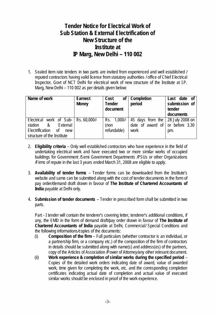
Tender Notice for Electrical Work ofSub Station & External Electrification of
New Structure of theInstitute at
IP Marg, New Delhi – 110 002
1. Sealed item rate tenders in two parts are invited from experienced and well established /reputed contractors having valid license from statutory authorities / office of Chief ElectricalInspector, Govt of NCT Delhi for electrical work of new structure of the Institute at I.P.Marg, New Delhi – 110 002 as per details given below:
Name of work EarnestMoney
Cost ofTenderdocument
Completionperiod
Last date ofsubmission oftenderdocuments
Electrical work of Sub-station & ExternalElectrification of newstructure of the Institute
Rs. 60,000/- Rs. 1,000/-(nonrefundable)
45 days from thedate of award ofwork
28 July 2008 onor before 3.30pm.
2. Eligibility criteria – Only well established contractors who have experience in the field ofundertaking electrical work and have executed two or more similar works of occupiedbuildings for Government /Semi Government Departments /PSUs or other Organizations/Firms of repute in the last 3 years ended March 31, 2008 are eligible to apply.
3. Availability of tender forms – Tender forms can be downloaded from the Institute’swebsite and same can be submitted along with the cost of tender documents in the form ofpay order/demand draft drawn in favour of The Institute of Chartered Accountants ofIndia payable at Delhi only.
4. Submission of tender documents – Tender in prescribed form shall be submitted in twoparts.
Part - I tender will contain the tenderer’s covering letter, tenderer’s additional conditions, ifany, the EMD in the form of demand draft/pay order drawn in favour of The Institute ofChartered Accountants of India payable at Delhi, Commercial/ Special Conditions andthe following informations/copies of the documents:(i) Composition of the firm – Full particulars (whether contractor is an individual, or
a partnership firm, or a company etc.) of the composition of the firm of contractorsin details should be submitted along with name(s) and address(es) of the partners,copy of the Articles of Association /Power of Attorney/any other relevant document.
(ii) Work experience & completion of similar works during the specified period –Copies of the detailed work orders indicating date of award, value of awardedwork, time given for completing the work, etc. and the corresponding completioncertificates indicating actual date of completion and actual value of executedsimilar works should be enclosed in proof of the work experience.
-4-
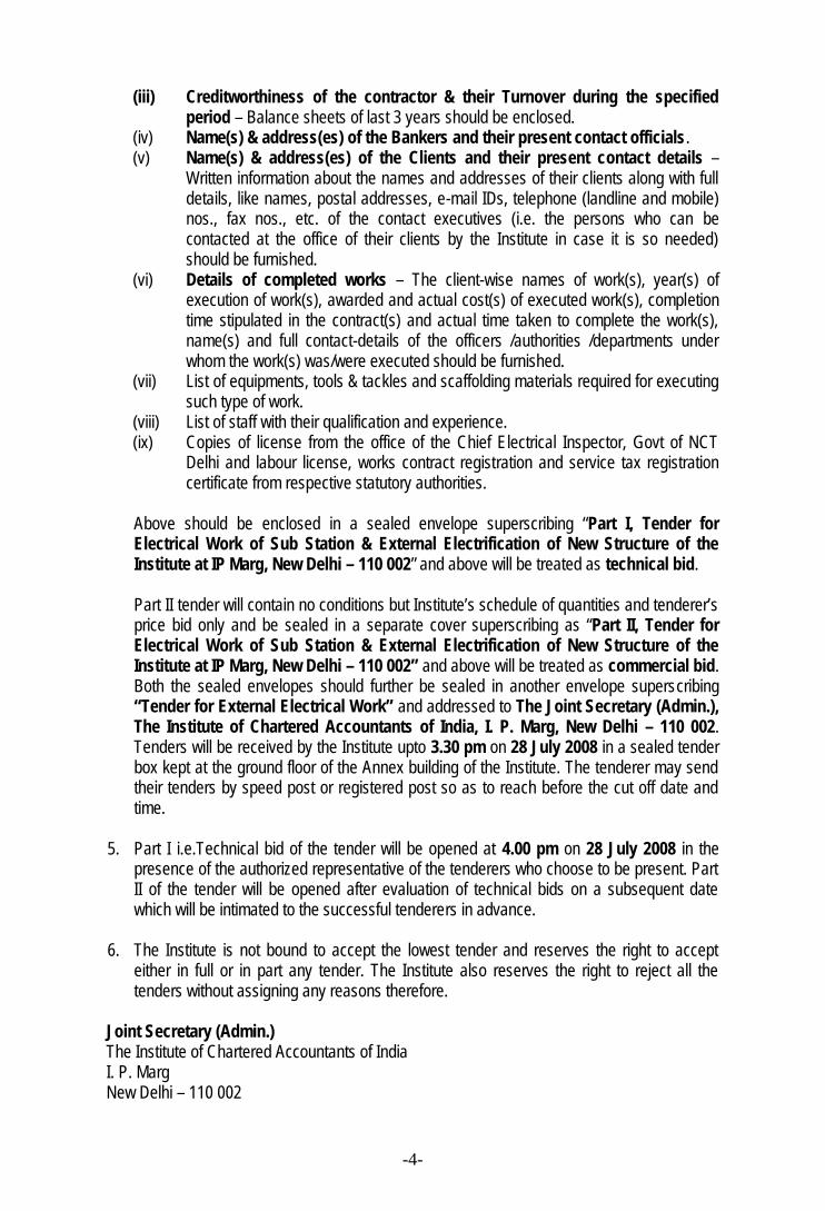
(iii) Creditworthiness of the contractor & their Turnover during the specifiedperiod – Balance sheets of last 3 years should be enclosed.
(iv) Name(s) & address(es) of the Bankers and their present contact officials.(v) Name(s) & address(es) of the Clients and their present contact details –
Written information about the names and addresses of their clients along with fulldetails, like names, postal addresses, e-mail IDs, telephone (landline and mobile)nos., fax nos., etc. of the contact executives (i.e. the persons who can becontacted at the office of their clients by the Institute in case it is so needed)should be furnished.
(vi) Details of completed works – The client-wise names of work(s), year(s) ofexecution of work(s), awarded and actual cost(s) of executed work(s), completiontime stipulated in the contract(s) and actual time taken to complete the work(s),name(s) and full contact-details of the officers /authorities /departments underwhom the work(s) was/were executed should be furnished.
(vii) List of equipments, tools & tackles and scaffolding materials required for executingsuch type of work.
(viii) List of staff with their qualification and experience.(ix) Copies of license from the office of the Chief Electrical Inspector, Govt of NCT
Delhi and labour license, works contract registration and service tax registrationcertificate from respective statutory authorities.
Above should be enclosed in a sealed envelope superscribing “Part I, Tender forElectrical Work of Sub Station & External Electrification of New Structure of theInstitute at IP Marg, New Delhi – 110 002” and above will be treated as technical bid.
Part II tender will contain no conditions but Institute’s schedule of quantities and tenderer’sprice bid only and be sealed in a separate cover superscribing as “Part II, Tender forElectrical Work of Sub Station & External Electrification of New Structure of theInstitute at IP Marg, New Delhi – 110 002” and above will be treated as commercial bid.Both the sealed envelopes should further be sealed in another envelope superscribing“Tender for External Electrical Work” and addressed to The Joint Secretary (Admin.),The Institute of Chartered Accountants of India, I. P. Marg, New Delhi – 110 002.Tenders will be received by the Institute upto 3.30 pm on 28 July 2008 in a sealed tenderbox kept at the ground floor of the Annex building of the Institute. The tenderer may sendtheir tenders by speed post or registered post so as to reach before the cut off date andtime.
5. Part I i.e.Technical bid of the tender will be opened at 4.00 pm on 28 July 2008 in thepresence of the authorized representative of the tenderers who choose to be present. PartII of the tender will be opened after evaluation of technical bids on a subsequent datewhich will be intimated to the successful tenderers in advance.
6. The Institute is not bound to accept the lowest tender and reserves the right to accepteither in full or in part any tender. The Institute also reserves the right to reject all thetenders without assigning any reasons therefore.
Joint Secretary (Admin.)The Institute of Chartered Accountants of IndiaI. P. MargNew Delhi – 110 002
-5-
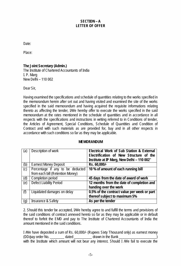
SECTION – ALETTER OF OFFER
Date:
Place:
The Joint Secretary (Admin.)The Institute of Chartered Accountants of IndiaI. P. MargNew Delhi – 110 002
Dear Sir,
Having examined the specifications and schedule of quantities relating to the works specified inthe memorandum herein after set out and having visited and examined the site of the worksspecified in the said memorandum and having acquired the requisite informations relatingthereto as affecting the tender, I/We hereby offer to execute the works specified in the saidmemorandum at the rates mentioned in the schedule of quantities and in accordance in allrespects with the specifications and instructions in writing referred to in Conditions of tender,the Articles of Agreement, Special Conditions, Schedule of Quantities and Condition ofContract and with such materials as are provided for, buy and in all other respects inaccordance with such conditions so far as they may be applicable.
MEMORANDUM
(a) Description of work Electrical Work of Sub Station & ExternalElectrification of New Structure of theInstitute at IP Marg, New Delhi – 110 002”
(b) Earnest Money Deposit Rs. 60,000/-(c) Percentage if any to be deducted
from each bill (Retention Money)10 % of amount of each running bill
(d) Completion period 45 days from the date of award of work(e) Defect Liability Period 12 months from the date of completion and
handing over the work(f) Liquidated damages on delay 0.5% of the contract value per week or part
thereof subject to maximum 5%(g) Insurance & Safety As per the tender
2. Should this tender be accepted, I/We hereby agree to and fulfill the terms and provisions ofthe said conditions of contract annexed hereto so far as they may be applicable or in defaultthereof to forfeit the EMD and pay to The Institute of Chartered Accountants of India theamount mentioned in the said conditions.
I /We have deposited a sum of Rs. 60,000/- (Rupees Sixty Thousand only) as earnest money(DD/pay order No. ________ dated __________ drawn in the Bank _____________________)with the Institute which amount will not bear any interest. Should I /We fail to execute the
-6-
contract when called upon to do so. I / We do hereby agree that this sum shall be forfeited byme /us to the Institute.
Name of the partner of the firm (tenderer) authorized to sign
Signature with seal
-7-
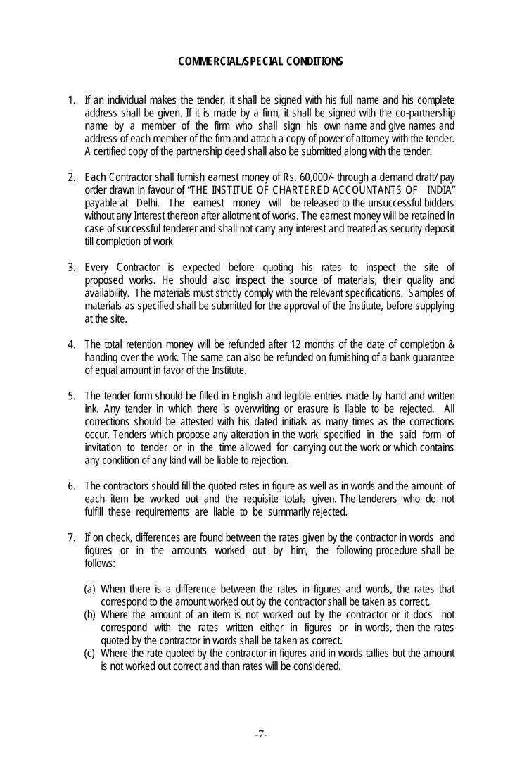
COMMERCIAL/SPECIAL CONDITIONS
1. If an individual makes the tender, it shall be signed with his full name and his completeaddress shall be given. If it is made by a firm, it shall be signed with the co-partnershipname by a member of the firm who shall sign his own name and give names andaddress of each member of the firm and attach a copy of power of attorney with the tender.A certified copy of the partnership deed shall also be submitted along with the tender.
2. Each Contractor shall furnish earnest money of Rs. 60,000/- through a demand draft/ payorder drawn in favour of “THE INSTITUE OF CHARTERED ACCOUNTANTS OF INDIA”payable at Delhi. The earnest money will be released to the unsuccessful bidderswithout any Interest thereon after allotment of works. The earnest money will be retained incase of successful tenderer and shall not carry any interest and treated as security deposittill completion of work
3. Every Contractor is expected before quoting his rates to inspect the site ofproposed works. He should also inspect the source of materials, their quality andavailability. The materials must strictly comply with the relevant specifications. Samples ofmaterials as specified shall be submitted for the approval of the Institute, before supplyingat the site.
4. The total retention money will be refunded after 12 months of the date of completion &handing over the work. The same can also be refunded on furnishing of a bank guaranteeof equal amount in favor of the Institute.
5. The tender form should be filled in English and legible entries made by hand and writtenink. Any tender in which there is overwriting or erasure is liable to be rejected. Allcorrections should be attested with his dated initials as many times as the correctionsoccur. Tenders which propose any alteration in the work specified in the said form ofinvitation to tender or in the time allowed for carrying out the work or which containsany condition of any kind will be liable to rejection.
6. The contractors should fill the quoted rates in figure as well as in words and the amount ofeach item be worked out and the requisite totals given. The tenderers who do notfulfill these requirements are liable to be summarily rejected.
7. If on check, differences are found between the rates given by the contractor in words andfigures or in the amounts worked out by him, the following procedure shall befollows:
(a) When there is a difference between the rates in figures and words, the rates thatcorrespond to the amount worked out by the contractor shall be taken as correct.
(b) Where the amount of an item is not worked out by the contractor or it docs notcorrespond with the rates written either in figures or in words, then the ratesquoted by the contractor in words shall be taken as correct.
(c) Where the rate quoted by the contractor in figures and in words tallies but the amountis not worked out correct and than rates will be considered.
-8-
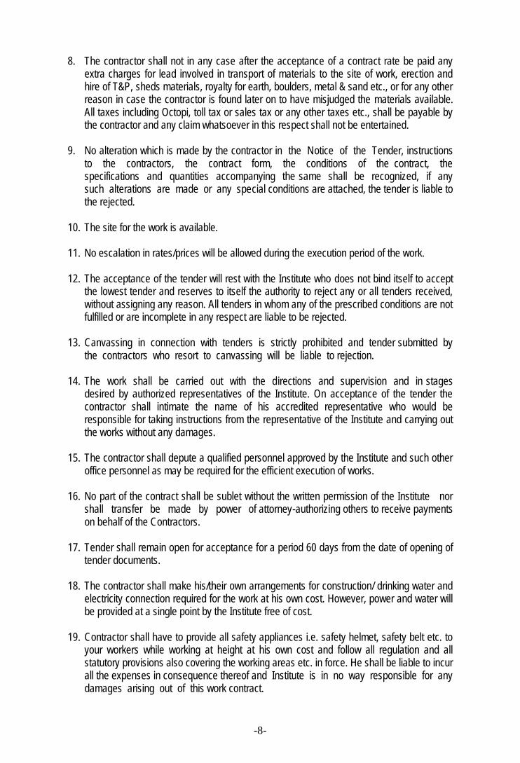
8. The contractor shall not in any case after the acceptance of a contract rate be paid anyextra charges for lead involved in transport of materials to the site of work, erection andhire of T&P, sheds materials, royalty for earth, boulders, metal & sand etc., or for any otherreason in case the contractor is found later on to have misjudged the materials available.All taxes including Octopi, toll tax or sales tax or any other taxes etc., shall be payable bythe contractor and any claim whatsoever in this respect shall not be entertained.
9. No alteration which is made by the contractor in the Notice of the Tender, instructionsto the contractors, the contract form, the conditions of the contract, thespecifications and quantities accompanying the same shall be recognized, if anysuch alterations are made or any special conditions are attached, the tender is liable tothe rejected.
10. The site for the work is available.
11. No escalation in rates/prices will be allowed during the execution period of the work.
12. The acceptance of the tender will rest with the Institute who does not bind itself to acceptthe lowest tender and reserves to itself the authority to reject any or all tenders received,without assigning any reason. All tenders in whom any of the prescribed conditions are notfulfilled or are incomplete in any respect are liable to be rejected.
13. Canvassing in connection with tenders is strictly prohibited and tender submitted bythe contractors who resort to canvassing will be liable to rejection.
14. The work shall be carried out with the directions and supervision and in stagesdesired by authorized representatives of the Institute. On acceptance of the tender thecontractor shall intimate the name of his accredited representative who would beresponsible for taking instructions from the representative of the Institute and carrying outthe works without any damages.
15. The contractor shall depute a qualified personnel approved by the Institute and such otheroffice personnel as may be required for the efficient execution of works.
16. No part of the contract shall be sublet without the written permission of the Institute norshall transfer be made by power of attorney-authorizing others to receive paymentson behalf of the Contractors.
17. Tender shall remain open for acceptance for a period 60 days from the date of opening oftender documents.
18. The contractor shall make his/their own arrangements for construction/ drinking water andelectricity connection required for the work at his own cost. However, power and water willbe provided at a single point by the Institute free of cost.
19. Contractor shall have to provide all safety appliances i.e. safety helmet, safety belt etc. toyour workers while working at height at his own cost and follow all regulation and allstatutory provisions also covering the working areas etc. in force. He shall be liable to incurall the expenses in consequence thereof and Institute is in no way responsible for anydamages arising out of this work contract.
-9-
20. The contractor shall indemnify the Institute for all kinds of injury or death on account of anylabour engaged by the contractor as well as property of the institute at the site of work.The contractors in this regard shall pay any compensation. The contractor shall beresponsible for all implications under labour Laws and Act of Delhi State and CentralGovernment (Including fire insurance).
21. The contractor shall be totally responsible for any damage to the building, buildingmaterial and his materials, equipment, caused due to fire, rain, flood, storm, or anyother natural calamilities at the site of work during construction period.
22. No bill less than Rs. 5,00,000.00 is to be submitted as running bill at one time.
23. No mobilization advance will be paid.
24. All works of operations and use of materials shall be as per specificationsmentioned only and as the directions of the representative of the Institute.
25. Arbitration - In case of any dispute of difference arising in relation tomeaning or interpretation of this order/agreement, the same shall be referred to a solearbitrator to be appointed by the President of the Institute. The Arbitration and ConciliationAct, 1996 will be applicable to the arbitration proceeding and the venue of the arbitrationshall be at New Delhi. The award of the arbitrator shall be final and binding.
26. The measurement of each item executed will be verified jointly and the payment shall bemade within 15 days of completion of the verification and submission of bill with verifiedmeasurement and duly certified by the consultant/ architect. If required certification ofquality of material/workmanship /work quantity executed will be get certified by anindependent architect/ consultant.
27. The contractor shall at all times abide by the instructions, directions given in respect of thematerials, workmanship etc.
28. Statutory Compliance - Contractor shall be responsible for complying with the applicablelaws/bye laws/Regulations in force from time to time.
Contractor shall have to bear all statutory liabilities as applicable to hisworkers/personnel engaged by him for the job. Nothing will be paid extra in this regard. IfInstitute pays any amount in this regard, the same amount will be deducted from the bill.
Contractor shall have to arrange insurance cover for the workers/personnel engaged byyou for the job. Also he will be responsible for all the dues of the workers/personnelengaged by him including the liabilities if any towards workmen compensation or under anyother law.
29. The contractor is required to cause the demolition of any sub standard work inrespect of materials and workmanship or both. The contractor must abide by all suchinstructions.
-10-
30. The contractor shall maintain, “site order book” at site where all instructions by the Instituteshall be recorded and the contractor shall abide by such instructions and sign the bookagainst each such instructions after compliance thereof.
31. Liquidated Damage - In case of non-completion of the work within stipulated period, thecontractor would be liable to pay penalty at the rate of 0.5% of the contract value perweek or part thereof to a maximum of 5% of the total amount of work.
32. FORCE MAJEURE: -If the work delays by: -(i) Acts of God(ii) Abnormally bad weather, or earthquake or floods or similar calamities.(iii) Serious loss or damage by fire or(iv) Civil commotion, local combination of workers strike or lockout or(v) Any other causes, which is the absolute discretion of the Institute and beyond
contractor’s control.
Then any force majors condition herein mentioned occur and continue for a periodexceeding 15 days the parties hereto undertake to sit together and devise forexpeditious and proper performance of the obligations of the parties under this order.
33. Samples of any materials can be had from the contractor free of cost.
34. The Contractor will obtain all necessary permissions/ certificates/ Approvals/NOCs for execution of the works on behalf of the Institute from the statutory/Government bodies like, Municipal Corporation of Delhi, Delhi Traffic Police, Chiefelectrical inspector, BSES etc. with his own arrangement and cost. However, anystatutory fees payable in this regard will be reimbursed to the contractor onsubmission of receipt of payment made.
35. The quoted rates should be inclusive of all taxes like excise duty, sales tax/ VAT,state entry tax, octroi, etc. including service tax.
36. The contractor is to follow up with M/s. BSES Yamuna Power Ltd. for shifting of meteringpanel from upper basement of existing annex building to the new location at ground floornear existing transformer area in the initial stage and again for shifting of the meteringcubical to the new location i.e. upper basement of the new structure after completion of thework.
37. The Contractor will purchase Insurance policy equivalent to the amount of work for aperiod of two months from the date of start of works.
38. The Contractor will quote the rates considering the prevailing taxes and Institute reservesthe right to ask for original purchase receipt of any material brought to the site.
39. The contractor will provide analysis of rate for any item quoted is so desired by theInstitute.
-11-
40. After completion of the work all the scaffolding materials are to be dismantled and removedfrom the premises of the Institute. All the malbas and debrises are to be removed and to bedumped in a dumpyard duly approved by the MCD with his own arrangement oftransportation by the contractor. All the surplus materials of the contractor are to beremoved and the site is to be cleaned in all respects and to be handed over to the Institute.No extra payment will be made in this regard.
41. Each page of the Tender Documents should be signed by the person or personssubmitting the tender in token of his/their having acquainted himself/themselves with theConditions of Contract, General Specifications, Special Condition, etc. as laid down. Anytender with any of the documents not so signed will be rejected.
42. The Institute reserves the right to sub-divide the work mentioned in the tender, among twoor more contractors at its own discretion and the contractors will have to execute theorders for part of the items placed with them at the quoted rates. The Institute alsoreserves the right to increase or decrease the quantities and even omit any items of workafter the order is placed and the Contractor shall execute the same without claiminganything extra for the same. In this context the rates quoted for each item must be selfsupporting and relevant.
43. On receipt of intimation from the Institute of the acceptance of his/their tenders, thesuccessful tenderer shall be bound to sign the formal contract and within seven daysthereof, the successful tender or shall sign as agreement in accordance by the Institute willbe binding on the contractor whether such formal agreement is or is not subsequentlyexecuted. The cost of necessary stamp paper for execution of the agreement shall beborne by the successful tender.
44. The Contractor should note that, unless otherwise stated the tender is strictly on item ratebasis and their attention is drawn to the fact that, rates for each and every item should becorrect, workable and self supporting. The quantities in the Schedule of Quantitiesapproximately indicate the total extent of work but may vary to any extent and may even beomitted thus altering the aggregate value of the contract. No claim shall be entertained onthis account. The contractor shall bring it to the notice of the Institute in case of any extraitems not mentioned in the Schedule of Quantities during the course of the work and shallonly carry out same on written approval from the Institute’s Engineer.
45. The successful tenderer must co-operate with any other contractor appointed by theInstitute so that the work shall proceed smoothly with least possible delay and to thesatisfaction of the Institute’s Engineer.
46. The Institute reserves the right to terminate the contract if the contractor fails to executethe job within the specified period or fails to keep the program of the work given by thecontractor and approved by the Institute.
47. Mode of payment: Payment shall be made through R.A. Bills for actual quantity executedand jointly measured as the work progresses. Retention money deposit (RMD) of 10% ofeach bill shall be deducted. TDS and DVAT will be deducted at the prevailing rate fromeach running bill. All payments will be made through account payee chqeue only to theparty.
-12-
48. Precaution should be taken by the contractor while execution /shifting of materials to theworkplace so that day to day working of the Institute will not be disturbed or stopped. Thecontractor should plan properly so that most of the work which causes maximum noisesmay be carried out in night of holidays. Proper care also should be taken while taking therenovation of the toilets so that no seepage occur to other floors.
49. After completion of the work the contractor is to clean the site and remove the wastagematerial and to dump the same at the site shown to him in the premises of the Institute.The malba related to the material supplied by the contractor is to be removed from the site/premises of the Institute at his own cost. The unused material supplied by the Institute isto be returned by the contractor to the store of the Institute.
50. The rates quoted should be most competitive and there will be no further negotiation.
APPENDIX ‘A’ SCHEDULE OF FISCAL ASPECTS
Terms of payment
a. Mobilization advance No mobilization advance will be paid.
b. EMD In the form of pay order/ demand draft only.
c. Value of work for interim certificate. Rs.5.00 Lacs (Work done)
d. Defect liability period 12 months from the date of handing over of the finalstage.
d. Security deposit. 10 % to be deducted from each running bill excludingearnest money. 50% of security deposit will be releasedafter the virtual completion and balance 50% to bereleased after the defect liability period of 12 months.
-13-
SPECIAL INSTRUCTION TO TENDERERS.
1.1 The entire electrification work shall be carried out by the licensed electrical contractor inaccordance with these specifications without any extra cost.
1.2 For the site supervision, the contractor must depute a qualified electrical engineer. Thecontractor shall employ only experienced and licensed wiremen to do the electrificationwork.
1.3 The work shall conform to relevant Indian standard Specifications the I.E. Acts and Rulesand the requirements of Local Electrical Authority.
1.4 When the installation is complete, the same shall be tested with the 500/1000 voltsMagger in the requirements of Local Electrical Authority.
1.5 Contractor shall submit to the client 3 sets of test certificates for the installation.1.6 The contractor shall carry out all civil works connected with the electrical job. The
contractors shall repair and make good the damage caused by him to the civil structurewhile executing the electrification of work. The foundation for the panel board and for thepoles, grouting of frames in the wall, erection of D.B./ switchboards in the wall / chasingthe walls for embedding the conduits and boxes etc. are all to be carried out by thecontractors including making good the damaged civil work.
1.7 The contractor has to submit shop drawings for the Sub-station equipment and electricaldistribution boards and the conduit layout to the Architects / Consultants for their approvalbefore starting the work. Also one set of approved sample of the materials have to bekept at site.
1.8 The Architect / Consultant will issue the drawings to the Contractors for carrying out thework.
1.9 The electrical contractor, his wire men and supervisors shall be qualified and have a validlicense while quoting as well as during the course of work. The contractor shall provide aqualified electrical engineer at site during the execution of work.
-14-
ARTICLES OF AGREEMENT
Articles of Agreement made the __________ day of ________ at _______________ betweenThe Institute of Chartered Accountants of India, having it Head Office at ICAI Bhawan, I.P.Marg, New Delhi – 110 002 (hereinafter referred to as the Institute) of the one part and M/s._____________ having its office at _____________________ (hereinafter referred to ascontractor) of the other part.
WHEREAS the Ins t i tu te is desirous of carrying out repairs and rehabilitation to its buildings atits headquarter at I. P. Marg, New Delhi – 110 002 and has caused the detailed specificationsdescribing the work to be done to be prepared by the Institute.
AND WHEREAS the said documents inclusive t h e specifications and the schedule ofquantities and price schedule have been signed by or on behalf of the parties hereto.
AND WHEREAS the contractor has agreed to execute upon and subject to the conditions setforth herein, hereinafter upon and subject to the conditions described in the saidspecifications and the said priced schedule of quantities at the respective rates mentioned in thepriced schedule of quantities therein set forth amounting to the sum Rs. ________ (total contractprice), which is part of the Tender document.
AND WHEREAS the contractor has deposited Rs.60,000/- (Rupees Sixty Thousand only) as theEarnest Money with the Institute, which shall become part of security deposit to be retained untilthe expiry of the Defect liability period for the due observance of the contract.
NOW IT IS HEARBY AS FOLLOWS
1. In consideration of the said contract, payments to be made to the said conditions executeand complete the works described in the said documents and such further detaileddrawings as may be furnished to him by the Institute and described in the specifications andthe said priced schedule of quantities.
2. The Institute shall pay the contractor such sums as shall become payablehereunder at the times and in the manner specified in the said conditions.
3. The said contract comprised the building above mentioned and all subsidiary worksconnected there within the same site as may be ordered to be done from time to timeby the Institute even though such works may not be shown on the Drawings or describedin the said specifications or the priced schedule of quantities.
4. The Institute reserves to himself the right of altering the drawings and nature of thework and adding to or omitting any items of work, check of measurement, paymentcertificate, variation arising in view of change of scope of work and approval of rates ofextra substituted items. The decision of the Institute shall be final and binding in- this regard.
5. The Institute in consultation with its consultants reserves the right to exercise control onquality of work, check of measurement, payment certificate, variation arising, in view ofchange of scope of work and approval of rates of extra substituted items. The
-15-
decision of the Institute shall be final and binding this regard.
6. The said conditions and appendix thereto shall be read and construed as forming part ofthis agreement, and the parties hereto shall respectively abide by, submit themselves to thesaid Conditions and perform the agreements on their part respectively in the said Conditionscontained.
7. The agreement and documents mentioned herein shall form the basis of this Contract.
8. This Contract is neither a fixed Lump Sum Contract nor a Piece Work Contract but acontract to carry out the work in respect of renovation work to be paid for according to actualmeasured quantities at the rate contained in the Schedule of rates and Probable Quantitiesor as provided in the said Conditions.
9. The Contractor shall afford every reasonable facility for the carrying out of all works in themanner laid down in the said Conditions and shall make good any damages done to walls,floors, etc. after the completion of such works.
10. The Institute reserves to itself the right of altering the Drawings and nature of the work byadding to or omitting any items of work or having portions of the same carried out withoutprejudice to this contract.
11. Time shall be considered as the essence of this Contract and the Contractor hereby agreesto commence the work soon after the site is handed over to him or from seventh day ofissue of formal work order/agreement was provided for in the said Conditions whichever islater and to complete the entire work within 75 days subjects nevertheless to the provisionsfor extensions of time.
12. Liquidated Damage - In case of non-completion of the work within stipulated period, thecontractor would be liable to pay penalty at the rate of 0.5% of the contract value perweek or part thereof to a maximum of 5% of the total amount of work.
13. All payments by the Institute under this Contract will be made only at Delhi.
14. In case of any dispute of difference arising in relation to meaning or interpretation of thisorder/agreement, the same shall be referred to a sole arbitrator to be appointed by thePresident of the Institute. The Arbitration and Conciliation Act, 1996 will be applicable to thearbitration proceeding and the venue of the arbitration shall be at New Delhi. The award ofthe arbitrator shall be final and binding.
15. The following documents shall be deemed to form and constructed as part of thisagreement along with the amendments, negotiated and confirmed in varioussubsequent letters exchanged as mentioned hereinafter and parties hereto willrespectively abide by and submit themselves to the conditions and stipulations andperform the agreement on their parts respectively in such conditions contained.
i) Notice inviting Tender.ii) Instruction to Tendersiii) Special Conditions of the contractiv) Technical Specificationsv) Schedule of Quantities
-16-
vi) Employer's letter dated ________________.vii) ____________/__________to the contractor awarding the contract.viii) Contractor's letter dated _______________/_____________/___________/ to the
Institute in acceptance of the award of contract.
15. The several parts of this contract have been read to us and fully understood by us.
SIGNED AND DELIVERED by THE INSTITUTE OF CHARTERED ACCOUNTANTS OF INDIA byhand ofSHRI(Name and Designation)
IN THE PRESENCE OF
(1)
ADDRESS
(2)ADDRESS
SIGNED BY THE CONTRACTOR
IN THE PRESENCE OF
(1)
ADDRESS
(2)ADDRESS
-17-
TECHNICAL SPECIFICATION
GENERAL1.01 Work involve additions alterations required for external electrical work to enable the
demolition of present annexe building and to enable continuity of supply to adjoiningmain building which is being supplied electricity from the basement of annexebuilding. The contractor shall visit the site and satisfy himself regarding the siteconditions. All the equipments mentioned in BOQ are to be installed in the first phasein a shed to be constructed by the side of existing transformers at ground floor.Suitable shed will be erected for the safety of the electrical equipment for installationby the owner. After completion of the structure equipments are again to be shifted tothe upper basement of the new structure permanently. Any approvals/ NOCs/Certificates required for the work from any statutory authorities/ government officesare to be obtained by the contractor with his own arrangement and cost. Onlystatutory fees paid in this regard will be reimbursed to the contractor on submissionof the receipt of the same.
1.02 The work as indicated in the scope of work attached herewith includes anymodification/addition/alteration required. Work shall be carried out as per thestandard/specifications indicated below:-i) Relevant ISS as modified upto date. Where IS codes do not exist, the British
Standards shall be followed.ii) Indian Electricity Rules 1956 as amended upto date.iii) CPWD Specifications for Electrical Works (Part – I) Internal, (Part –II) External 1995
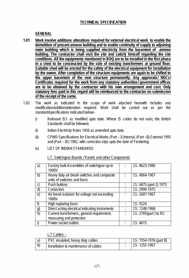
and (Part – IV) 1982, with correction slips upto the date of Tendering.iv) LIST OF INDIAN STANDARDS
L.T. Switchgear Boards / Panels and other Components
a) Factory built Assemblies of switchgear up to1000V
: I.S: 8623-1980
b) Heavy duty air break switches and compositeunits of switches and fuses
: I.S: 4064-1967
c) Push buttons : I.S: 6875 (part 2) 1973d) Contactors : I.S: 2999-1975e) Air break isolators for voltage not exceeding
1000V: I.S: 2607-1967
f) High rupturing fuses : I.S: 9224g) Direct acting electrical indicating instruments : I.S: 1248-1968h) Current transformers, general requirement,
measuring and protective: I.S: 2705(part I to IV)
i) Power socket outlets : I.S: 4615
L.T Cables: -a) PVC insulated, heavy duty cables : I.S: 1554-1976 (part II)b) Installation & maintenance of cables : I.S: 1255-1967
-18-
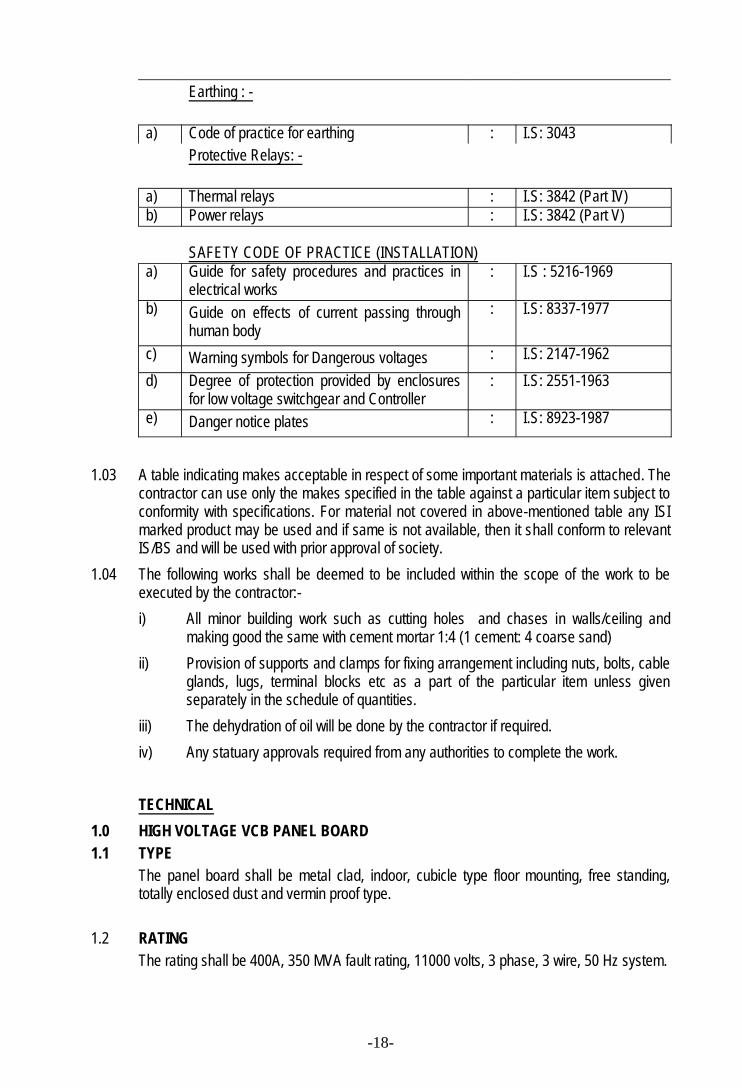
Earthing : -
a) Code of practice for earthing : I.S: 3043Protective Relays: -
a) Thermal relays : I.S: 3842 (Part IV)b) Power relays : I.S: 3842 (Part V)
SAFETY CODE OF PRACTICE (INSTALLATION)a) Guide for safety procedures and practices in
electrical works: I.S : 5216-1969
b) Guide on effects of current passing throughhuman body
: I.S: 8337-1977
c) Warning symbols for Dangerous voltages : I.S: 2147-1962d) Degree of protection provided by enclosures
for low voltage switchgear and Controller: I.S: 2551-1963
e) Danger notice plates : I.S: 8923-1987
1.03 A table indicating makes acceptable in respect of some important materials is attached. Thecontractor can use only the makes specified in the table against a particular item subject toconformity with specifications. For material not covered in above-mentioned table any ISImarked product may be used and if same is not available, then it shall conform to relevantIS/BS and will be used with prior approval of society.
1.04 The following works shall be deemed to be included within the scope of the work to beexecuted by the contractor:-i) All minor building work such as cutting holes and chases in walls/ceiling and
making good the same with cement mortar 1:4 (1 cement: 4 coarse sand)ii) Provision of supports and clamps for fixing arrangement including nuts, bolts, cable
glands, lugs, terminal blocks etc as a part of the particular item unless givenseparately in the schedule of quantities.
iii) The dehydration of oil will be done by the contractor if required.iv) Any statuary approvals required from any authorities to complete the work.
TECHNICAL1.0 HIGH VOLTAGE VCB PANEL BOARD1.1 TYPE
The panel board shall be metal clad, indoor, cubicle type floor mounting, free standing,totally enclosed dust and vermin proof type.
1.2 RATINGThe rating shall be 400A, 350 MVA fault rating, 11000 volts, 3 phase, 3 wire, 50 Hz system.
-19-
1.3 CONSTRUCTIONCubicle type compartmentalised construction with not less than 2/1.6mm thick CRCA sheetsteel having separate compartments for busbars, cable termination, instrumentation andprotection gears. The housing structure shall he welded construction to support the coverand panels rigidly. The circuit breakers shall be drawout with provision I the panel fordrawout trolley arrangement. Earth termination shall be brought out for earth systemconnecting to panel.
1.4 DESIGN ASPECTSThe HT panel board shall be designed with consideration that the switch gear instrumentsprotective relays, bus bars, wiring etc. carried out should have following facilities.a) Facilities for inspection, maintenance and repairs, testing terminal for ease to external
test connections.b) Minimum noise and vibration levels as per relevant Indian Standards.c) Risk of accidental short circuits and open circuits.d) Secured and vibration proof connections for power and control circuits.e) Risk and accidental contacts of live parts; and danger to human lives.
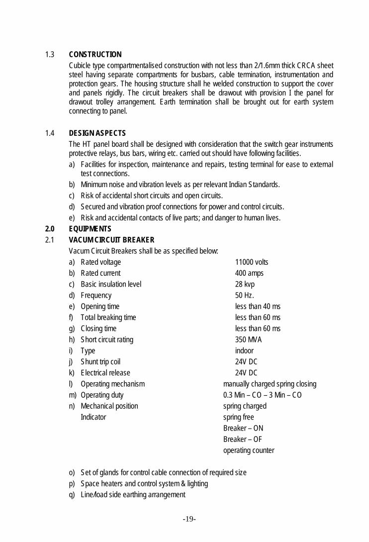
2.0 EQUIPMENTS2.1 VACUM CIRCUIT BREAKER
Vacum Circuit Breakers shall be as specified below:a) Rated voltage 11000 voltsb) Rated current 400 ampsc) Basic insulation level 28 kvpd) Frequency 50 Hz.e) Opening time less than 40 msf) Total breaking time less than 60 msg) Closing time less than 60 msh) Short circuit rating 350 MVAi) Type indoorj) Shunt trip coil 24V DCk) Electrical release 24V DCl) Operating mechanism manually charged spring closingm) Operating duty 0.3 Min – CO – 3 Min – COn) Mechanical position spring charged
Indicator spring freeBreaker – ONBreaker – OFoperating counter
o) Set of glands for control cable connection of required sizep) Space heaters and control system & lightingq) Line/load side earthing arrangement
-20-
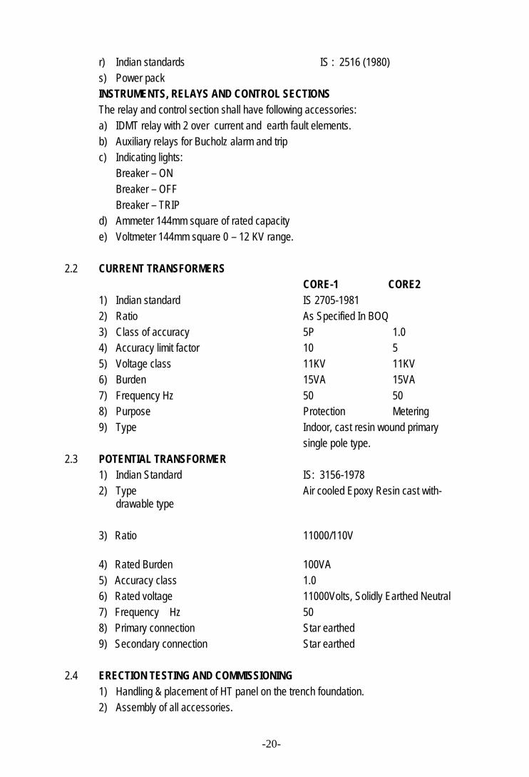
r) Indian standards IS : 2516 (1980)s) Power packINSTRUMENTS, RELAYS AND CONTROL SECTIONSThe relay and control section shall have following accessories:a) IDMT relay with 2 over current and earth fault elements.b) Auxiliary relays for Bucholz alarm and tripc) Indicating lights:
Breaker – ONBreaker – OFFBreaker – TRIP
d) Ammeter 144mm square of rated capacitye) Voltmeter 144mm square 0 – 12 KV range.
2.2 CURRENT TRANSFORMERSCORE-1 CORE2
1) Indian standard IS 2705-19812) Ratio As Specified In BOQ3) Class of accuracy 5P 1.04) Accuracy limit factor 10 55) Voltage class 11KV 11KV6) Burden 15VA 15VA7) Frequency Hz 50 508) Purpose Protection Metering9) Type Indoor, cast resin wound primary
single pole type.2.3 POTENTIAL TRANSFORMER
1) Indian Standard IS: 3156-19782) Type Air cooled Epoxy Resin cast with-
drawable type
3) Ratio 11000/110V
4) Rated Burden 100VA5) Accuracy class 1.06) Rated voltage 11000Volts, Solidly Earthed Neutral7) Frequency Hz 508) Primary connection Star earthed9) Secondary connection Star earthed
2.4 ERECTION TESTING AND COMMISSIONING1) Handling & placement of HT panel on the trench foundation.2) Assembly of all accessories.
-21-
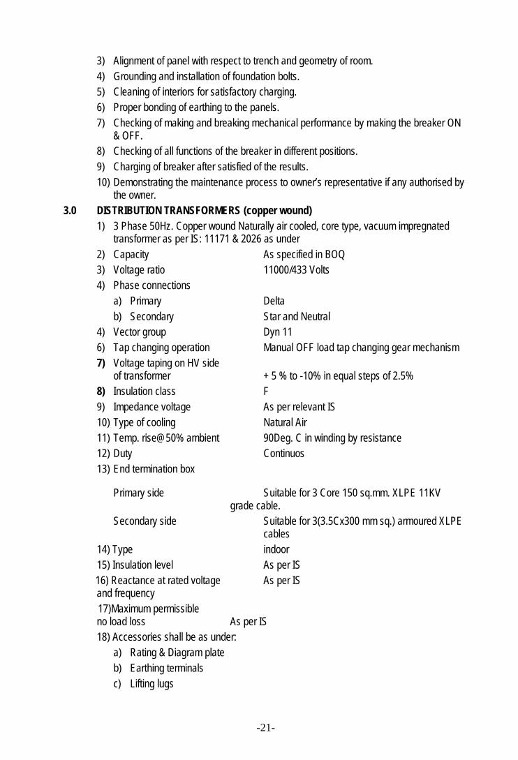
3) Alignment of panel with respect to trench and geometry of room.4) Grounding and installation of foundation bolts.5) Cleaning of interiors for satisfactory charging.6) Proper bonding of earthing to the panels.7) Checking of making and breaking mechanical performance by making the breaker ON
& OFF.8) Checking of all functions of the breaker in different positions.9) Charging of breaker after satisfied of the results.10) Demonstrating the maintenance process to owner’s representative if any authorised by
the owner.3.0 DISTRIBUTION TRANSFORMERS (copper wound)
1) 3 Phase 50Hz. Copper wound Naturally air cooled, core type, vacuum impregnatedtransformer as per IS: 11171 & 2026 as under
2) Capacity As specified in BOQ3) Voltage ratio 11000/433 Volts4) Phase connections
a) Primary Deltab) Secondary Star and Neutral
4) Vector group Dyn 116) Tap changing operation Manual OFF load tap changing gear mechanism7) Voltage taping on HV side
of transformer + 5 % to -10% in equal steps of 2.5%8) Insulation class F9) Impedance voltage As per relevant IS10) Type of cooling Natural Air11) Temp. rise@50% ambient 90Deg. C in winding by resistance12) Duty Continuos13) End termination box
Primary side Suitable for 3 Core 150 sq.mm. XLPE 11KVgrade cable.
Secondary side Suitable for 3(3.5Cx300 mm sq.) armoured XLPEcables
14) Type indoor15) Insulation level As per IS
16) Reactance at rated voltage As per ISand frequency
17)Maximum permissibleno load loss As per IS18) Accessories shall be as under:
a) Rating & Diagram plateb) Earthing terminalsc) Lifting lugs
-22-
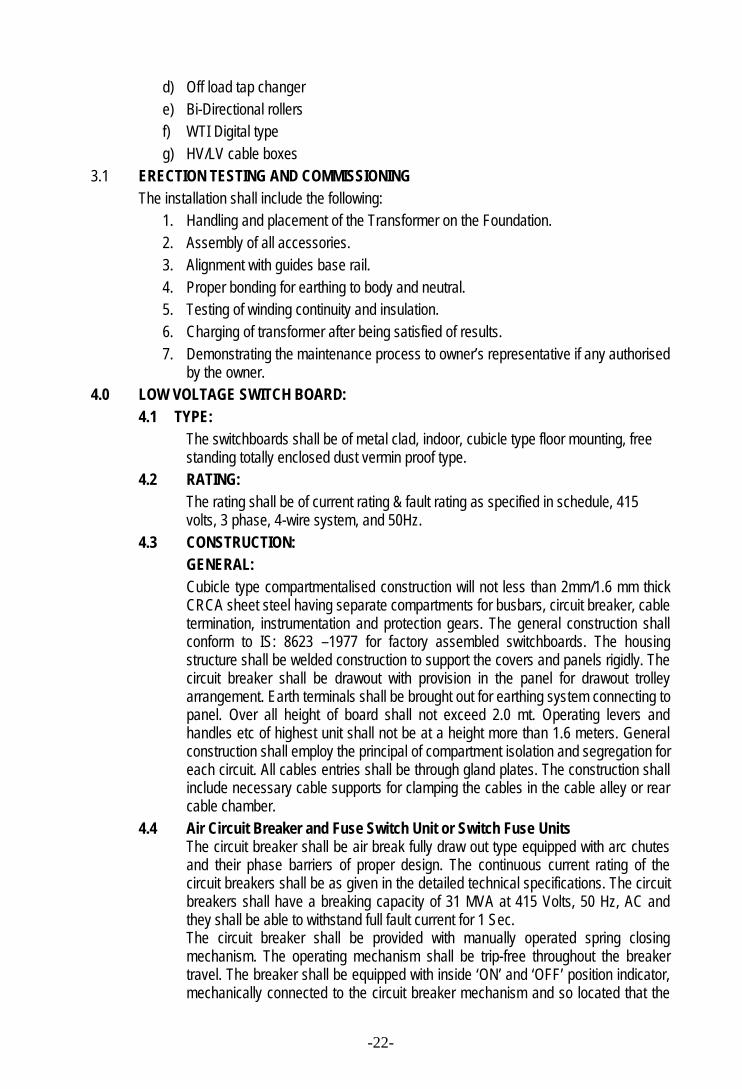
d) Off load tap changere) Bi-Directional rollersf) WTI Digital typeg) HV/LV cable boxes
3.1 ERECTION TESTING AND COMMISSIONINGThe installation shall include the following:
1. Handling and placement of the Transformer on the Foundation.2. Assembly of all accessories.3. Alignment with guides base rail.4. Proper bonding for earthing to body and neutral.5. Testing of winding continuity and insulation.6. Charging of transformer after being satisfied of results.7. Demonstrating the maintenance process to owner’s representative if any authorised
by the owner.4.0 LOW VOLTAGE SWITCH BOARD:
4.1 TYPE:The switchboards shall be of metal clad, indoor, cubicle type floor mounting, freestanding totally enclosed dust vermin proof type.
4.2 RATING:The rating shall be of current rating & fault rating as specified in schedule, 415volts, 3 phase, 4-wire system, and 50Hz.
4.3 CONSTRUCTION:GENERAL:Cubicle type compartmentalised construction will not less than 2mm/1.6 mm thickCRCA sheet steel having separate compartments for busbars, circuit breaker, cabletermination, instrumentation and protection gears. The general construction shallconform to IS: 8623 –1977 for factory assembled switchboards. The housingstructure shall be welded construction to support the covers and panels rigidly. Thecircuit breaker shall be drawout with provision in the panel for drawout trolleyarrangement. Earth terminals shall be brought out for earthing system connecting topanel. Over all height of board shall not exceed 2.0 mt. Operating levers andhandles etc of highest unit shall not be at a height more than 1.6 meters. Generalconstruction shall employ the principal of compartment isolation and segregation foreach circuit. All cables entries shall be through gland plates. The construction shallinclude necessary cable supports for clamping the cables in the cable alley or rearcable chamber.
4.4 Air Circuit Breaker and Fuse Switch Unit or Switch Fuse UnitsThe circuit breaker shall be air break fully draw out type equipped with arc chutesand their phase barriers of proper design. The continuous current rating of thecircuit breakers shall be as given in the detailed technical specifications. The circuitbreakers shall have a breaking capacity of 31 MVA at 415 Volts, 50 Hz, AC andthey shall be able to withstand full fault current for 1 Sec.The circuit breaker shall be provided with manually operated spring closingmechanism. The operating mechanism shall be trip-free throughout the breakertravel. The breaker shall be equipped with inside ‘ON’ and ‘OFF’ position indicator,mechanically connected to the circuit breaker mechanism and so located that the
-23-
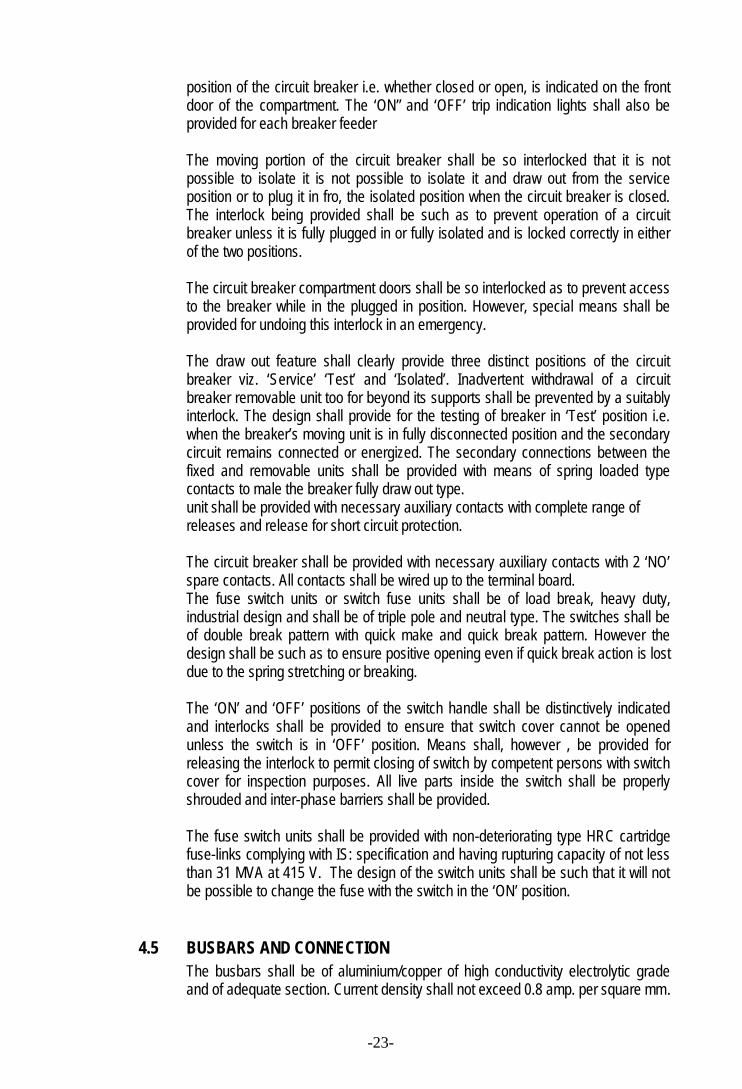
position of the circuit breaker i.e. whether closed or open, is indicated on the frontdoor of the compartment. The ‘ON” and ‘OFF’ trip indication lights shall also beprovided for each breaker feeder
The moving portion of the circuit breaker shall be so interlocked that it is notpossible to isolate it is not possible to isolate it and draw out from the serviceposition or to plug it in fro, the isolated position when the circuit breaker is closed.The interlock being provided shall be such as to prevent operation of a circuitbreaker unless it is fully plugged in or fully isolated and is locked correctly in eitherof the two positions.
The circuit breaker compartment doors shall be so interlocked as to prevent accessto the breaker while in the plugged in position. However, special means shall beprovided for undoing this interlock in an emergency.
The draw out feature shall clearly provide three distinct positions of the circuitbreaker viz. ‘Service’ ‘Test’ and ‘Isolated’. Inadvertent withdrawal of a circuitbreaker removable unit too for beyond its supports shall be prevented by a suitablyinterlock. The design shall provide for the testing of breaker in ‘Test’ position i.e.when the breaker’s moving unit is in fully disconnected position and the secondarycircuit remains connected or energized. The secondary connections between thefixed and removable units shall be provided with means of spring loaded typecontacts to male the breaker fully draw out type.unit shall be provided with necessary auxiliary contacts with complete range ofreleases and release for short circuit protection.
The circuit breaker shall be provided with necessary auxiliary contacts with 2 ‘NO’spare contacts. All contacts shall be wired up to the terminal board.The fuse switch units or switch fuse units shall be of load break, heavy duty,industrial design and shall be of triple pole and neutral type. The switches shall beof double break pattern with quick make and quick break pattern. However thedesign shall be such as to ensure positive opening even if quick break action is lostdue to the spring stretching or breaking.
The ‘ON’ and ‘OFF’ positions of the switch handle shall be distinctively indicatedand interlocks shall be provided to ensure that switch cover cannot be openedunless the switch is in ‘OFF’ position. Means shall, however , be provided forreleasing the interlock to permit closing of switch by competent persons with switchcover for inspection purposes. All live parts inside the switch shall be properlyshrouded and inter-phase barriers shall be provided.
The fuse switch units shall be provided with non-deteriorating type HRC cartridgefuse-links complying with IS: specification and having rupturing capacity of not lessthan 31 MVA at 415 V. The design of the switch units shall be such that it will notbe possible to change the fuse with the switch in the ‘ON’ position.
4.5 BUSBARS AND CONNECTIONThe busbars shall be of aluminium/copper of high conductivity electrolytic gradeand of adequate section. Current density shall not exceed 0.8 amp. per square mm.
-24-
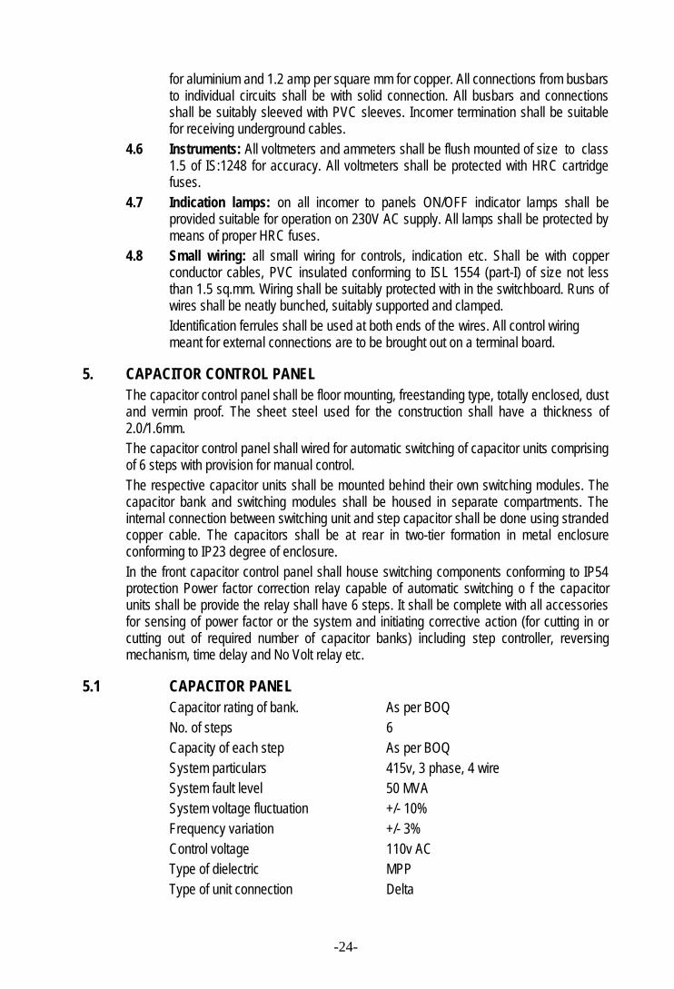
for aluminium and 1.2 amp per square mm for copper. All connections from busbarsto individual circuits shall be with solid connection. All busbars and connectionsshall be suitably sleeved with PVC sleeves. Incomer termination shall be suitablefor receiving underground cables.
4.6 Instruments: All voltmeters and ammeters shall be flush mounted of size to class1.5 of IS:1248 for accuracy. All voltmeters shall be protected with HRC cartridgefuses.
4.7 Indication lamps: on all incomer to panels ON/OFF indicator lamps shall beprovided suitable for operation on 230V AC supply. All lamps shall be protected bymeans of proper HRC fuses.
4.8 Small wiring: all small wiring for controls, indication etc. Shall be with copperconductor cables, PVC insulated conforming to ISL 1554 (part-I) of size not lessthan 1.5 sq.mm. Wiring shall be suitably protected with in the switchboard. Runs ofwires shall be neatly bunched, suitably supported and clamped.Identification ferrules shall be used at both ends of the wires. All control wiringmeant for external connections are to be brought out on a terminal board.
5. CAPACITOR CONTROL PANELThe capacitor control panel shall be floor mounting, freestanding type, totally enclosed, dustand vermin proof. The sheet steel used for the construction shall have a thickness of2.0/1.6mm.The capacitor control panel shall wired for automatic switching of capacitor units comprisingof 6 steps with provision for manual control.The respective capacitor units shall be mounted behind their own switching modules. Thecapacitor bank and switching modules shall be housed in separate compartments. Theinternal connection between switching unit and step capacitor shall be done using strandedcopper cable. The capacitors shall be at rear in two-tier formation in metal enclosureconforming to IP23 degree of enclosure.In the front capacitor control panel shall house switching components conforming to IP54protection Power factor correction relay capable of automatic switching o f the capacitorunits shall be provide the relay shall have 6 steps. It shall be complete with all accessoriesfor sensing of power factor or the system and initiating corrective action (for cutting in orcutting out of required number of capacitor banks) including step controller, reversingmechanism, time delay and No Volt relay etc.
5.1 CAPACITOR PANELCapacitor rating of bank. As per BOQNo. of steps 6Capacity of each step As per BOQSystem particulars 415v, 3 phase, 4 wireSystem fault level 50 MVASystem voltage fluctuation +/- 10%Frequency variation +/- 3%Control voltage 110v ACType of dielectric MPPType of unit connection Delta
-25-
Ambient temp. 48 Deg.CDuty continuous
6. POWER AND CONTROL CABLESAll cables of 11KV grade shall be XLPE cables whereas cables up to 1100v grade shall beXLPE/PVC insulated PVC sheathed as specified in BOQ.Cables shall be capable of satisfactory performance when laid on trays, in trenches,conduits, ducts and when directly buried in ground. Depth of lying in ground shall be 900mm. In conduits space factor of not more than 60%.The estimated lengths of cables of various sizes are indicated in price schedule. Whiletender would be adjusted on the basis of estimated lengths, the successful tenderer shall beresponsible to supply the actual length required at site for cabling all the circuits at the unitrate indicated in his tender.6.1 Technical requirements of Installation work of Power and control Cable
These cables are required for arranging power supply to the equipment beinginstalled. The cables shall be buried directly in ground outside the buildingswhereas within a plant room shall be laid in duct/on walls with proper clamps andsupports on MS fabricated cable racks. The details and arrangement of cable layingshall be got approved.
6.2 Cable installation workThe cables are to be buried directly underground, but when the feeder cables enterthe building, it id to be taken in cable racks/trays/GI pipes depending upon theindividual installations.The cables shall be run in the trenches about 0.90 metre bellow the finished groundlevel and protected n top by bricks all along their runs. The cables shall lie if a bedof sand 75mm below and 75mm above and be surrounded with sand as well. Thecable trenches shall be refilled only with good earth in successive layers of 150mmand ramming. A heap of about 200mm should be left over the filled cable trench,and no blocks of stones or any other heavy material shall be used for back filling.When directly buried cable cross the roads together with other service lines takenalong the same road which come in the way of cable crossing, the cables shall beproperly protected. All necessary protection must be given to cables as may berequired for particular installation conditions.
At points where the cable come out from masonry building for direct burialunderground, they must be taken out through hume pipes/GI pipes grouted in thewalls of the buildings. The pipes shall be so placed that their edges do not damagethe cable. For taking out the cables from the building trenches of requisiterectangular openings will be provided in the building walls and the selectedcontractor shall have to place the pipes in position and fill up the remaining portionsof the opening with cement/plaster/concrete.The sealing should be done in such a way that there is no leaking into the buildingfrom outside. after drawing of cables through the pipes, this will be properly packedwith water proof bituminous packing.The masonry work shall be properly finished to match with the architecturalarrangements.All along the route of direct burial cables, cable markers of permanent nature and ofdesign to be approved by the company shall be laid above the ground level to
-26-
indicate the routes of the cables. The manner in which the markers shall be placedwill be decided in consultation with the company and with his approval. If jointboxes are used the position of the same shall be indicated by suitable markers.All cables when laid in ducts in Plant building and other areas shall be suitablyclamped by means of cable clamps of approved design all along their routes oncable racks/trays. The clamps shall be so arranged that the individual cables arefastened to position but the clamping pressure does not damage any of the cables.On cable tray/rack normally only a single layer of cable shall be used and where thenumber of cables are more the cable/rack shall be made in double tier formation.Bending of GI pipes/conduits where required shall be done so as not to damage ordeform the walls of GI pipe/conduit. Installation shall be so planned as to provide forpulling facilities for cable without damage. Adequate number of inspection typejunction boxes and pull boxes shall be provided for this purpose.For all cable installation work due consideration shall be given to this permissibleradius of bends for individual cables. Where a cable of different diameter is run inone plane and are bent, the radius of bends shall be so selected that cables remainparallel to one another.For all cable runs, whether direct burial of on trays/rack etc. Individual cables shallbe provided with cable identification tags of a permanent type and design to beapproved by the company.GI pipes/. GI flexible pipes and accessories used in the installation shall conform toI.S. 1953. All GI pipes class B shall have galvanised surfaces and shall be lapwelded type and they shall be supplied in standard length.
6.3 LT XLPE CABLES:Type XLPE insulated Al. Conductor.Armouring Armoured/unarmoured as called in BOQConductor copper or aluminium as specified in BOQVoltage grade 1100 VoltsNo. of cores 2, 3., 3.5 or 4 as called for in BOQColour codes Phases: Red, Yellow, Blue, Neutral Black.Indian Standards IS: 7098 Part-I & II
6.4 HT CABLES:Type Cross Linked Polyethylene Insulated (XLPE)
Armouring Armoured/unarmoured as called in BOQConductor copper or aluminium as specified in BOQVoltage grade 11000 Volts (E)No. of cores 3., or as called for in BOQColour codes Phases: Red, Yellow, and BlueIndian Standards IS: 7098 Part-I
-27-
7.1 EARTHINGAll the non-current metal parts of electrical installation shall be earthed properly.All metal conduits, trunking, cable sheaths, switchgear, outlet boxes, distribution boards,light fittings, fans and all other parts made of metal or conductive material shall be bondedtogether and connected by means of specified earthing system.All earthing will be in conformity with the relevant provision of Rules 33 and 61 of the IndianElectricity Rules 1956 and Indian Standard Specifications IS:3043-1987 with latestamendments.
7.2. EARTHING CONDUCTORSAll earthing conductors shall be of high conductivity electrolytic copper of 99 % purity andshall be protected against mechanical injury or corrosion.
7.3 SIZING OF EARTHING CONDUCTORSThe cross sectional area of copper earthing conductor shall be same as the activeconductor for sizes of active copper conductor upto 4.0 sq. mm. and shall be half the sizefor 16 sq.mm. active copper conductor and above. All fixtures, fans, outlet boxes andjunction boxes shall be earthed with 1.5 sqmm PVC Insulated copper conductor wires. Allpower sockets and single phase A/C units shall be earthed with 4.0 PVC Insulated copperconductor wires. All Three phase Final Distribution Boards shall be earthed with 2 nos. 4mm dia bare copper conductor wires. The sizes of the earth continuity conductors shouldnot be less than half of the largest current carrying conductors.The Sub-Distribution Board shall be earthed to 2 nos. 600mm x 600mm x 3mm copper/G.I.plate earthing stations through 25m x 3 mm copper strips.
7.4 CONNECTION OF EARTHING CONDUCTORSMain earthing conductors shall be taken from the earth connections at the mainswitchboards to an earth electrode with which the connection is to be made. Submainearthing conductors shall run from the main switchboard to the sub-distribution boards.Final distribution boards earthing conductors shall run from sub-distribution boards.
7.5 PROHIBITED CONNECTIONSNeutral conductor, sprinkler pipes, or pipes conveying gas, water, or inflammable liquid,structural steel work, metallic enclosures or cables and conductors, metallic conduits andlightning protection system conductors shall not be used as a means of earthing aninstallation or even as a link in an earthing system. The electrical resistance of metallicenclosures for cables and conductors measured between earth connections at the mainswitchboard and any other point on the completed installation shall be low enough to permitthe passage of current necessary to operate fuse or circuit breakers and shall not exceed 1ohm.
7.6 PROTECTION FROM CORROSION
Connections between copper and galvanised equipment shall be made on vertical face andprotected with paint and grease. Galvanised fixing clamps shall not be used for fixing earthconductors. Only copper fixing clamps shall be used for fixing earth conductors. Whenthere is evidence that the soil is aggressive to copper, buried earthing conductors shall beprotected by suitable serving and sheathing.
7.7 EARTHING STATIONPlate Electrode Earthing : Earthing electrode shall consist of a tinned copper plate not lessthan 300mm x 300mm x 3mm thick/900mm x 900mmx 6 mm G.I/600 mm x 600 mm x 6
-28-
mm G.I. as called for in the Schedule. The plate electrode shall be buried as far aspracticable below permanent moisture level but in any case not less than 3 meters belowground level. Wherever possible earth electrodes shall be located as near the water tap,water drain or a down take pipe as possible. Earth electrodes shall not be installed inproximity to a metal fence. It shall be kept clear of the buildings foundations and in no caseshall it be nearer than 2 meters from the outer face of the wall. The earth plate shall be setvertically and surrounded with 150mm thick layer of charcoal, dust and salt mixture. 20mmGI pipe shall run from the top edge of the plate to the ground level. The top of the pipe shallbe provided with a funnel and a mesh for watering the earth through a pipe. The funnelover the GI Pipe shall be housed in a masonry chamber, approximately 300mm x 300mm x300mm deep. The masonry chamber shall be provided with a cast iron cover resting over aGI frame embedded in masonry. Refer Sketch for additional details.
Pipe Electrode Earthing: Earthing electrode shall consist of a GI Pipe (class ‘A’) IndianTube Company make or approved equal not less than 40mm dia and 4.5 meters long. GIPipe electrode shall be cut tapered at the bottom and provided with holes of 12mm diadrilled at 75mm interval upto 2.5 meters length from bottom. The electrode shall be buriedvertically in the ground as far as practicable below permanent moisture level with its top notless than 1.25 M below ground level. The electrode shall be in one piece and no joints shallbe allowed in the electrode. Wherever possible earth electrodes shall be located as nearwater tap, water drain or a down take pipe. Earth electrodes shall not be located inproximity to a metal fence. It shall be kept clear of the building foundations and in no caseshall be nearer than 2 meters from the outer face of the wall. Refer Sketch for additionaldetails.
The pipe earth electrode shall be kept vertically and surrounded with 150mm thick layer ofcharcoal dust and salt mixture upto a height of 2.5 meters from the bottom. At the top of theelectrode a funnel with a mesh shall be provided for watering the earth. The main earthconductors shall be connected to the electrode just below the funnel, with proper terminallugs and check nuts. The funnel over the GI pipe and earth connection housed in amasonry chamber, approximately 350mm deep. The masonry chamber shall be providedwith a cast iron cover resting over a CI frame embedded in masonry.
7.8. EARTH CONNECTION
All metal clad switches and other equipment carrying single phase current, shall beconnected to earth by a single connection. All metal clad switches carrying medium voltageand high voltage shall be connected with earth by two separate and distinct connections.The earthing conductors inside the building wherever exposed shall be properly protectedfrom mechanical injury by running the same in GI Pipe of adequate size.
Earthing conductors outside the building shall be laid 600mm below the finished groundlevel. The over lapping in copper strips at joints where required, shall be minimum 75mm.The joints shall be riveted and brazed with copper rivets and greased in approved manner.Sweated lugs of adequate capacity and size shall be used for all termination of wires above1 Sqmm size and bare copper wire above 2.0mm dia. Lugs shall be bolted to theequipment body after the metal body is cleaned of paint and other oily substance andproperly tinned. The earth wires entering the Final Distribution Boards shall be terminatedwith copper sockets crimped to its ends and tightened to the terminal with the help of flatend brass screws.
-29-
7.9. EARTH RESISTANCEThe earth resistivity of the soil where the earthing stations are located shall be submitted tothe Architects before the earthing work starts and get the approval of the Architects/Society.If the earth resistance is too high and multiple electrode earthing does/not give adequatelow resistance to earth, than the soil resistively immediately surrounding the earthelectrodes shall be reduced by adding sodium chloride, calcium chloride, sodium carbonate,copper sulphate, salt and soft coke or charcoal in suitable proportions as directed by theArchitects.
7.10. RESISTANCE TO EARTH
The resistance of each earth system shall not exceed 1.0 ohm in the case of MediumVoltage system and 0.5 ohm in the case of High Voltage system.
--------------

-30-
Concept Note regarding External Electrification work of addition and alteration in theInstitute building.
Work of external electrification of building has been divided into two parts.
Part one of the external electrification has to be carried out before demolition of annexe building.Equipment required for part one has been designed in such a way that it would be used in finalstage of part two also.
Work of part two pertains to final shifting of the equipment to the basement of new Annexe Building.
Part one pertains to shifting of equipment from the basement and to maintain the continuity ofelectric supply to the main building till completion of new annexe building. This part one mainlyconstitutes of following activities
1.Fabrication and supply of main LT Panel and installing the same at ground floor near thetransformers.
2. Dismantle and shifting of DG’s AMF Panel from the basement of annexe to ground floor nearmain LT Panel.
3. Connection of newly installed AMF Panel to DG and main LT Panel.
4. Connection of main building distribution boards (cables) to the main LT Panel.
5. Energisation of main LT Panel from DG set.
6. Steps 1 to 5 above will result in restoration of electric supply to the main building from DG set .
7. Getting the BSES Yamuna Power limited main HT metering panel shifted temporarily from thebasement of annexe to suitable place near transformers at ground floor. This work will be carried outby BSES. CA institutes to write a letter in advance to BSES in this regard. Follow up work will be putin the scope of external electrical contractor. Official charges for this work will be paid by the CAInstt.
8.Supply and installation of 11 KV 3 Panel Vacumn Circuit Breaker (VCB) panel at ground floor .
9. Dismantling of HT and LT terminations of two numbers existing transformers.
10. Connection of BSES metering panel to VCB panel and from VCB Panel to transformers.
11. Connection of LT terminals of transformers to the main LT Panel.
12. Energization of transformers from BSES supply..
-31-
13. Steps No.7 to 12 will result in restoring BSES supply to the main building and DG set will be puton emergency.
Once activities from Serial No. 1 to 13 of Part -1 are completed demolition of annexe building canstart.
Part 2 of external electrical work will start once the annexe building is completed .Various activitiesfor this Part-2 are as under .
a. Main LT panel will be disconnected from BSES transformer supply and put on DG supply tomaintain electricity to the main building during the transit period.
b. BSES will be asked to shift the metering panel from ground floor to its new permanentlocation in basement of annexe.
c. Dismantling of HT VCB 3 panel board and shifting the same to the basement of Annexe.
d. Two number new dry type transformers of 500 KVA each will be procured and installed inbasement.
e. HT cable connection from metering panel to 11KV VCB Panel and from 11KV VCB panel totransformers will be made.
f. New LT cables to be laid from position of main LT Panel in basement to distribution boardsin main building.
g. Dismantling of main LT Panel from ground floor and shifting the same to the basement.
h. Dismantling of DG’s AMF Panel and shifting the same to basement.
i. Connection from LT side of transformer and AMF panel to the main LT panel.
j. Energisation of supply from BSES to the transformers.
Steps a to j mentioned above will results in completion of electrical supply to the main and annexebuilding.
Tender for external electrical work will be made in two parts. Part 1will be executed at present andPart 2 will be completed after completion of annexe building. Every effort will be made to maincontinuity of supply to the main building during the transit period.
-32-
Present electrical equipment installed in the basement of annexe is very old and obsolete exceptAMF panel. As such all equipment except AMF panel will be discarded. Since oil type equipmentcan not be installed in basement there-fore new dry type transformers will be installed.
In order to accommodate the shifting of equipment from basement to the side of transformers acovered shed will have to be put in place by removing the cooling towers which are redendent.Details of shed will be given as soon as new equipment details are available.
-33-
THE INSTITUTE OF CHARTERED ACCOUNTANTS OF INDIA
PART – II(COMMERCIAL BID)
TENDER FORELECTRICAL WORK FOR
SUB-STATION & EXTERNAL ELECTRIFICATIONOF NEW STRUCTURE OF THE
INSTITUTE ATI.P. MARG,
NEW DELHI – 110 002
Name of tenderer: -
Address:
Last Date of Submission of 28 July 2008Tender Documents: - on or before 3.30 pm