tender specification - bharat heavy electricals ltd. · tender specification ... for any special...
TRANSCRIPT

TENDER SPECIFICATION
BHEL PSSR SCT 1324
FABRICATION & ERECTION OF STRUCTURAL STEEL IN POWER
HOUSE, MILL BUNKER BAY, AUXILLIARY BUILDINGS AND PIPE
RACK ETC
FOR
2 X 600 MW TPP
FOR
TAMIL NADU ELECTRICITY BOARD
ATHIPATTU, TAMIL NADU
VOLUME – II BOOK 1
TECHNICAL SPECIFICATION
BOOK NO …
BHARAT HEAVY ELECTRICALS LIMITED ( A GOVERNMENT OF INDIA UNDERTAKING)
POWER SECTOR – SOUTHERN REGION 690,ANNA SALAI, NANDANAM, CHENNAI – 600 035

POWERING TAMIL NADU’S PROGRESS…
Specification No:SE/E/T&H(P)/No.175 / 2007-2008 Volume-V: Technical Specification-Civil
500 MW NCTPS STAGE-II VOL-V/SEC-C3
Section C3
TECHNICAL SPECIFICATIONS Section C3 – TECHNICAL SPECIFICATIONS..................................................................1 to 241 1 Surveying Works ............................................................................................... 1
2 Soil Investigation ............................................................................................... 2
3 Earthwork and Rockwork.................................................................................. 7
4 Concrete Works............................................................................................... 20
5 Structural Steel Work
a) Fabrication................................................................................................. 54
b) Erection ..................................................................................................... 77
6 Chimney ...................................................................................................... 92
7 Masonry and Plastering Works..................................................................... 120
8 Water Proofing .............................................................................................. 124
9 Plumbing & sanitary Installations.................................................................. 128
10 Metal Work .................................................................................................... 135
11 Miscellaneous Metal and allied Works ......................................................... 144
12 Joinery ..................................................................................................... 147
13 Glazing ..................................................................................................... 149
14 Painting ................................................................................................. 151
15 Tiling and Flooring......................................................................................... 154
16 False ceiling .................................................................................................. 172
17 False Flooring................................................................................................ 175
18 Sheet work in roofing and siding .................................................................. 177
POWERING TAMIL NADU’S PROGRESS…
Specification No:SE/E/T&H(P)/No.175 / 2007-2008 Volume-V: Technical Specification-Civil
500 MW NCTPS STAGE-II VOL-V/SEC-C3
19 Drainage and Sewerage ............................................................................... 180
20 Roads and Pavement ................................................................................... 186
21 Chain link fencing ......................................................................................... 219
22 Landscaping .................................................................................................. 222
23 Piling Works .................................................................................................. 223

BHEL: PSSR: SCT: 1324: VOL II: BOOK 1
INDEX
Sl. No. Applicable Specification Pg. Nos.
1.0 Structural Steel Works 56 – 96
2.0 Metal work 140 – 149
3.0 Misc. metal & allied works 150 – 152
4.0 Sheet work in Roof & siding 182 – 184

POWERING TAMIL NADU’S PROGRESS…
Specification No:SE/E/T&H(P)/No.175 / 2007-2008 Volume-V: Technical Specification-Civil
500 MW NCTPS STAGE-II 56 VOL-V/SEC-C3
thorough mixing. It is advisable to mix the blend of aluminium powder thoroughly with sand and cement before water is added because aluminium powder has a tendency to float on water.
4.26.4 Proprietary material of approved manufacture used as an admixture to obtain
non-shrinking grout shall be mixed in the proportion of 1:1:1 (1 cement: 1 admixture: 1 sand), or as per manufacturer’s instructions.
4.26.5 Pre-mixed non-shrinking grout shall be used all as per manufacturer’s instructions
and without any additional materials/admixtures such as cement, sand and aggregates etc.
5 STRUCTURAL STEEL WORK PART I FABRICATION OF STRUCTURAL STEEL WORK 5.01.00 SCOPE This specification covers supply and/or taking delivery of raw steel materials from
owner's stores, fabrication, testing, painting and delivery to site of structural steelwork including supply of all consumable stores and bolts, nuts, washers, electrodes and other materials required for fabrication and field connections of all structural steelwork in general covered under the scope of the contract. However, for any special structures such as rail & road bridges, steel chimney, tanks, transmission towers, furnace structures, etc., the relevant Indian Standard or IRC specification and Codes of Practices shall be given due consideration over & above this specification.
5.02.00 GENERAL 5.02.01 Work to be provided for by the Contractor The work to be provided for by the Contractor, unless otherwise specified
elsewhere in the contract, shall include, but not be limited to the following :- a) Preparation of complete detailed fabrication drawings and erection
marking drawings required for all the structures covered under the scope of the contract based on design drawings to be furnished by the Owner.
b) To submit revised design with calculations and detailed fabrication
drawings in case any substitution of the designed sections are to be made.
c) To submit design calculations for joints and connections developed by
the contractor along with detailed fabrication drawings.

POWERING TAMIL NADU’S PROGRESS…
Specification No:SE/E/T&H(P)/No.175 / 2007-2008 Volume-V: Technical Specification-Civil
500 MW NCTPS STAGE-II 57 VOL-V/SEC-C3
d) Prepare and submit monthly materials reconciliation statement showing effective utilization of raw steel materials as received from Owner's stores.
e) Furnish quarterly and monthly requirement of matching steel sections for
maintaining required progress of fabrication in accordance with the approved programme and take delivery of all raw steel materials from Owner's stores or supply of such matching steel sections in case the same are not supplied by the owner.
f) Furnish all materials, labour, tools and plant and all consumables required for
fabrication and supply, all necessary bolts, nuts, washers, tie rods and welding electrodes for field connections. The field connection materials supplied by the contractor shall be to the extent of actual requirement plus 10% ( ten percent).
g) Furnish shop painting of all fabricated steelwork as per requirements of
this Specification. h) Suitably mark, bundle and pack for transport all fabricated materials. i) Prepare and furnish detailed Bill of Materials, Drawing Office Despatch
lists, Bolt List and any other list of bought out items required in connection with the fabrication and erection of the structural steelwork.
j) Insure, load and transport all fabricated steelwork field connection
materials to site. k) Furnish necessary test certificates of all raw steel material supplied by
the Contractor. 5.02.02 Work by others No work under this specification will be provided for by any agency other than
the contractor, unless specifically mentioned otherwise elsewhere in the contract. 5.02.03 Codes and standards All work under this specification shall, unless otherwise specified in the contract,
conform to the requirements of the latest revision and/or replacements of the following or any other relevant Indian Standard specifications and codes of practice. In case any particular aspect of the work is not specifically covered by any Indian Standard Specification, any other standard practice, as may be specified by the Engineer shall be followed:-

POWERING TAMIL NADU’S PROGRESS…
Specification No:SE/E/T&H(P)/No.175 / 2007-2008 Volume-V: Technical Specification-Civil
500 MW NCTPS STAGE-II 58 VOL-V/SEC-C3
LIST OF IS CODES - RELEVANT TO FABRICATION OF STRUCTURAL STEEL WORK
IS Codes D e s c r i p t i o n
IS:800 - Code of practice for general construction in steel.
IS:801 - Code of practice for use of cold formed light gauge steel structural members in general building construction.
IS:806 - Code of practice for use of steel tubes in general building
construction.
IS:808 - Dimensions for rolled steel beams, channels and angle sections.
IS:812 - Glossary of terms relating to welding & cutting of metals. IS:813 - Scheme of symbols for welding.
IS:814 - Covered electrodes for metal arc welding of carbon and carbon manganese steel.
IS:815 - Classification coding of covered electrodes for metal arc welding
of mild steel and low alloy high tensile steel.
IS:816 - Code of practice for use of metal arc welding for general construction in mild steel.
IS:817 - Code of practice for training & testing metal arc welders.
IS:818 - Code of practice for safety and health requirements in electric and gas welding and cutting operations.
IS:819 - Code of practice for resistance spot welding for light assemblies in
mild steel. IS:822 - Code of practice for inspection of welds.
IS:919 - Recommendations for limits and fits for (Part - 1&2) engineering.
IS:1161 - Steel Tubes for structural purposes.
IS:1182 - Recommended practice for Radiographic Examination of fushion welded butt joints in steel plates.
IS:1200 - Method of measurement of steel work and iron (Part - 8 ) work.
IS:1239 - Mild steel tubes, tubular and other wrought (Part - 1&2) steel
fittings

POWERING TAMIL NADU’S PROGRESS…
Specification No:SE/E/T&H(P)/No.175 / 2007-2008 Volume-V: Technical Specification-Civil
500 MW NCTPS STAGE-II 59 VOL-V/SEC-C3
IS:1363 - Hexagon head bolts, screws and nuts of product (Part - 1 to 3)
grade C.
IS:1364 - Hexagon head bolts, screws and nuts of product (Part - 1 to 5) grade A & B.
IS:1365 - Slotted counter sunk head screws (dia. 1.6 to 20 mm)
IS:1367 - Technical supply conditions for threaded steel (Part - 1 to 18) fasteners.
IS: 1608 - Method for tensile testing of steel products.
IS:1730 - Dimensions for steel plate, sheet and strip for structural and general engineering purposes.
IS:1852 - Rolling and cutting tolerances for hot-rolled steel product. IS:1977 - Structural steel (Ordinary quality) IS:2016 - Plain washer IS:2062 - Steel for general structural purposes.
IS:2629 - Recommended practice for hot-dip galvanizing of iron and steel.
IS:2633 - Method for testing uniformity of coating on zinc coated articles.
IS:3644 - Code of practice for ultrasonic pulse echo testing by contact and immersion method.
IS:3757 - High Strength Structural Bolt IS:4000 - High strength bolts in steel structure
IS:4759 - Specifications for hot-dip zinc coatings on structural steel and other allied products.
IS:4923 - Hollow steel sections for structural use.
IS:5334 - Code of practice for magnetic particle flaw detection of weld. IS:5369 - General requirements for plain washers and lock washer. IS:6005 - Code of practice for phosphating of iron and steel.
IS:6649 - Specification for hardened and tempered washers for high strength structural bolts and nuts.

POWERING TAMIL NADU’S PROGRESS…
Specification No:SE/E/T&H(P)/No.175 / 2007-2008 Volume-V: Technical Specification-Civil
500 MW NCTPS STAGE-II 60 VOL-V/SEC-C3
IS:6623 - Specification for high strength structural nuts. IS:7215 - Tolerances for fabrication of steel structures. IS:7280 - Bare wire electrode for submerged arc welding
IS:8500 - Structural steel micro alloyed (medium & high strength quality).
IS:8629 - Code of practice for protection of iron and (Part - I to III) steel structures from atmospheric corrosion.
IS:9595 - Recommendation for metal arc welding of carbon manganese
steels. PAINTING
IS:117 - Specification for ready mixed paint, brushing, finishing, exterior, semi-gloss, for general purposes.
IS:128 - Specification for ready mixed paint, brushing, finishing, semi-gloss
for general purposes, black. IS:1477 - Code of practice for painting of ferrons metal (Part - I & II) in
building.
IS:2074 - Ready mixed paint, air-drying red-oxide zinc chrome priming.
IS:2339 - Specification for aluminium paints for general purposes in dual container.
IS:2932 - Specification for enamel, synthetic exterior type - I.
IS:2933 - Specification for enamel, synthetic exterior type - II.
5.02.04 Conformity with Designs Except where the standard connection details are furnished, the contractor shall
design all connections, supply and fabricate all steelwork and furnish all connection materials in accordance with the approved drawings and/or as instructed by the Engineer Keeping in view the maximum utilization of the available sizes and sections of steel materials. The methods of painting, marking, packing and delivery of all fabricated materials shall be in accordance with the provisions of the contract and/or as approved by the Engineer. Provision of all relevant Indian Standard Specifications and Codes of Practice shall be followed unless otherwise specified in the contract.

POWERING TAMIL NADU’S PROGRESS…
Specification No:SE/E/T&H(P)/No.175 / 2007-2008 Volume-V: Technical Specification-Civil
500 MW NCTPS STAGE-II 61 VOL-V/SEC-C3
5.02.05 Materials to be used a) General All steel materials shall be free from all imperfections, mill scales, slag intrusions,
laminations, pittings, rusts etc. that may impair their strength, durability and appearance. All materials shall be of tested quality only unless otherwise permitted by the Engineer and/or Consultant.
If desired by the Engineer, Test Certificates of materials supplied by the
contractor in respect of each consignment shall be submitted in triplicate. Whenever the materials are required to be used from unidentified stocks, if permitted by the Engineer, a random sample shall be tested at an approved laboratory from each lot of 50 tonnes or less of any particular section.
The arc welding electrodes shall conform to the relevant Indian Standard Codes
of Practice and Specifications and shall be of heavily coated type and the thickness of the coating shall be uniform and concentric. With each container of electrodes, the manufacturer shall furnish instructions giving recommended voltage and ampereage ( Polarity in case of D.C. supply ) for which the electrodes are suitable.
b) Steel All steel materials to be used in construction within the purview of this
specification shall comply with any of the following Indian Standard Specifications as may be applicable : -
1) IS : 801 - Cold formed light gauge steel structural member. 2) IS : 806 - Steel tubes in general building construction. 3) IS : 1161 - Steel tubes for structural purpose. 4) IS : 1977 - Structural steel (Ordinary quality) St-42-0 5) IS : 2062 - Steel for general structural purpose 6) IS : 8500 - Structural steel-microalloyed (Ordinary & high strength
quality) In case of imported steel materials being used, these shall conform to
specifications equivalent to any of the above as may be applicable. c) Electrodes All electrodes to be used under the Contract shall comply with any of the
following Indian Standard Specifications as may be applicable : -
POWERING TAMIL NADU’S PROGRESS…
Specification No:SE/E/T&H(P)/No.175 / 2007-2008 Volume-V: Technical Specification-Civil
500 MW NCTPS STAGE-II 62 VOL-V/SEC-C3
1) IS : 814 - Covered electrodes for metal arc welding structural steel 2) IS : 815 - Classification and coding of covered electrodes for metal
arc welding of mild steel and low alloy high tensile steel. 3) IS : 7280 - Base wire electrode for submerged arc welding. d) Bolts and Nuts All bolts and nuts shall conform to the requirements of Indian Standard
Specification IS:1367 - Technical Supply Conditions for Threaded Fasteners. Materials for Bolts and nuts under the purview of this contract shall comply with
any of the following Indian Standard Specifications as may be applicable. a) Mild Steel : All mild steel for bolts and nuts when tested in accordance
with the following Indian Standard Specification shall have a tensile strength of not less than 44 Kg/mm2 and a minimum elongation of 23 per cent on a gauge length of 5.6 √A, where 'A' is the cross sectional area of the test specimen : -
1) IS:1367 - Technical supply conditions for threaded
fastners.
2) IS:1608 - Method for tensile testing of steel other than sheet,
strip, wire and tube. b) High Tensile Steel : The material used for the manufacture of high tensile
steel bolts and nuts shall have the mechanical properties appropriate to the particular class of steel as set out in IS:1367 or as approved by the Engineer.

POWERING TAMIL NADU’S PROGRESS…
Specification No:SE/E/T&H(P)/No.175 / 2007-2008 Volume-V: Technical Specification-Civil
500 MW NCTPS STAGE-II 63 VOL-V/SEC-C3
e) Washers Washers shall be made of steel conforming to any of the following Indian
Standard Specifications as may be applicable under the provisions of the Contract : -
1) IS : 1977 - Structural steel (Ordinary Quality) St-42-0 2) IS : 2062 - Steel for general structural purpose 3) IS : 8500 - Structural steel – microalloyed (medium & high strength
quality) 4) IS : 6623 - High Strength Structural Nuts 5) IS : 6649 - Hardened and tampered washers for high strength
structural bolts & nuts. f) Paints Paints to be used for shop coat of fabricated steel under the purview of this
contract shall conform to the Indian Standard Specification IS:2074 - Ready mixed Paint, Air Drying, Red Oxide - Zinc Chromate Priming.
In highly corrosive environment other type of primer such as epoxy rasin based
zinc rich primer (such as blast steel EZ1 of Shalimer Paints Ltd., or equivalent) may be necessary.
5.02.06 STORAGE OF MATERIAL a) General All materials shall be so stored as to prevent deterioration and to ensure the
preservation of their quality and fitness for the work. Any material which has deteriorated or has been damaged shall be removed from the contractor's yard immediately, failing which, the Engineer shall be at liberty to get the material removed and the cost incurred thereof shall be realised from the Contractor. The Contractor shall maintain upto date accounts in respect of receipt, use and balance of all sizes and sections of steel and other materials. In case the fabrication is carried out in contractor's fabrication shop outside the plant site where other fabrication works are also carried out, all materials meant for use in this contract shall be stacked separately with easily identifiable marks.
b) Steel The steel to be used in fabrication and the resulting cut pieces shall be stored in
separate stacks off the ground sectionwise and lengthwise so that they can be easily inspected, measured and accounted for at any time. If required by the Engineer, the materials may have to be stored under cover and suitably painted for protection against weather.

POWERING TAMIL NADU’S PROGRESS…
Specification No:SE/E/T&H(P)/No.175 / 2007-2008 Volume-V: Technical Specification-Civil
500 MW NCTPS STAGE-II 64 VOL-V/SEC-C3
c) Electrodes The electrodes for electric are welding shall be stored in properly designed
racks, separating different types of electrodes in distinctly marked compartments. The electrodes shall be kept in a dry and warm condition if necessary by resorting to heating.
d) Bolts, Nuts and Washers Bolts, nuts and washers and other fastening materials shall be stored on racks
off the ground with a coating of suitable protective oil. These shall be stored in separate gunny bags or compartments according to diameter, length and quality.
e) Paints Paints shall be stored under cover in air tight containers. Paints supplied in
sealed containers shall be used up as soon as possible once the container is opened.
5.02.07 Quality Control The Contractor shall establish and maintain quality control procedures for
different items of work and materials to the extent he deems necessary to ensure that all work is performed in accordance with this specification. In addition to the Contractor's quality control procedures, materials and workmanship at all times shall be subjected to inspection by the Engineer or Engineer's representative. As far as possible, all inspection by the Engineer or Engineer's representative shall be made at the Contractor's fabrication shop whether located at Site or elsewhere. The Contractor shall co-operate with the Engineer or Engineer's representative in permitting access for inspection to all places where work is being done and in providing free of cost all necessary help in respect of tools and plants, instrument, labour and materials required to carry out the inspection. The inspection shall be so scheduled as to provide the minimum interruption to the work of the Contractor.
Materials or workmanship not in reasonable conformance with the provisions of
this Specification may be rejected at any time during the progress of the work. The quality control procedure shall cover but not be limited to the following items
of work : - 1) Steel : Quality, manufacturer's test certificates, test reports
of representative samples of materials from unidentified stocks if permitted to be used.
2) Bolts, Nuts : Manufacturer's certificate, dimension Washers
checks, Material testing.
POWERING TAMIL NADU’S PROGRESS…
Specification No:SE/E/T&H(P)/No.175 / 2007-2008 Volume-V: Technical Specification-Civil
500 MW NCTPS STAGE-II 65 VOL-V/SEC-C3
3) Electrodes : Manufacturer's certificate, thickness and quality of
flux coating. 4) Welders : Qualifying Tests 5) Welding sets : Performance Tests 6) Welds : Inspection, X-ray, Ultrasonic tests 7) Paints : Manufacturer's certificate, physical inspection
reports 8) Galvanizing : Tests in accordance with IS : 2633 - Method for
testing uniformity of coating on Zinc Coated Articles and IS : 4759 - Specification for Hot- Dip Zinc coatings on Structural Steel and other allied products.
5.02.08 Standard dimensions, forms and weights The dimensions, forms, weights and tolerances of all rolled shapes bolts, nuts,
studs, washers etc. and other members used in the fabrication of any structure shall, wherever applicable, conform to the requirements of the latest relevant Indian Standards, wherever they exist, or, in the absence of Indian Standards, to other equivalent standards.
5.02.09 Shop Drawings The contractor shall within thirty (30) days after the award of the Contract submit
to the Engineer the Schedule of Fabrication and delivery of structural steelwork for approval. He shall within forty five (45) days after the award of the contract start to submit progressively for approval, the shop drawings based on the Design Drawings furnished to him and, before proceeding with the fabrication work, shall get the said shop drawings approved in accordance with the contract.
The sequence of submission of shop drawings for approval shall match with the
approved fabrication and delivery schedule. The approval for the shop drawings will be accorded only towards the general conformity with the design requirements as well as specification and will ensure the correctness of general arrangement for centerline dimensions and levels, Section sizes, and adequacy of connections including splice joints as to the no. of bolts, weld length, size of gusset/end plates. The correctness of all other details like cutting lengths, matching of holes, notch dimensions, match markings, bill of materials, bolt list etc. will be entirely the contractor's responsibility. The approval of the drawing however shall not relieve the contractor of his sole responsibility in carrying out the work correctly and fulfilling the complete requirements of contract documents.

POWERING TAMIL NADU’S PROGRESS…
Specification No:SE/E/T&H(P)/No.175 / 2007-2008 Volume-V: Technical Specification-Civil
500 MW NCTPS STAGE-II 66 VOL-V/SEC-C3
The shop drawings shall include but not be limited to the following : - a) Assembly drawings giving exact sizes of the sections to be used and
identification marks of the various sections. b) Dimensional drawings of base plates, foundation bolt location etc. c) Details of all connections with supporting calculations. d) Comparison sheets to show that the proposed alternative section,if any,
are as strong as the original sections shown on the Design Drawings. e) Complete Bill of Materials and detailed drawings of all sections as also
their billing weights. f) Any other drawings or calculations that may be required for the
clarification of the works or substituted parts thereof. The shop drawings shall give all the necessary information for the fabrication,
erection and painting of the steelwork in accordance with the provisions of this Specification. Shop drawings shall be made in accordance with the best modern practice and with due regard to sequence, speed and economy in fabrication and erection. Shop drawings shall give complete information necessary for fabrication of various components of the steelwork, including the location, type, size and extent of welds. These shall also clearly distinguish between shop and field bolts and welds and specify the class of bolts and nuts. The drawings shall be drawn to a scale large enough to convey all the necessary information adequately. Notes on the shop drawings shall indicate those joints or groups of joints in which it is particularly important that the welding sequence and technique of welding shall be carefully controlled to minimize the locked -up stresses and distortion. Welding symbols used shall be in accordance with the requirements of the Indian Standard Specification --IS:813 - Scheme of symbols for Welding, and shall be consistent throughout. Weld lengths called for on the drawings shall mean the net effective length.
The Contractor shall be responsible for and shall pay for any alterations of the
work due to any discrepancies, errors or omissions on the drawings or other particulars supplied by him, whether such drawings or other particulars have been duly approved or not in accordance with the Contract.
5.03.00 WORKMANSHIP 5.03.01 Fabrication a) General All workmanship shall be equal to the best practice in modern structural shops,
and shall conform to the provisions of the Indian Standard IS:800 - Code of Practice for use of Structural Steel in General Building Construction and other relevant Indian Standards or equivalent.
POWERING TAMIL NADU’S PROGRESS…
Specification No:SE/E/T&H(P)/No.175 / 2007-2008 Volume-V: Technical Specification-Civil
500 MW NCTPS STAGE-II 67 VOL-V/SEC-C3
b) Straightening Material Rolled materials before being laid off or worked, must be clean, free from sharp
kinks, bends or twists and straight within the tolerances allowed by the Indian Standard Specification IS:1852 - Specification for rolling and cutting tolerance for hot-rolled steel products. If straightening is necessary, it may be done by mechanical means or by the application of a limited amount of localized heat. The temperature of heated areas, as measured by approved methods, shall not exceed 600 Deg. C.
c) Cutting Cutting shall be effected by shearing, cropping or sawing. Use of a mechanically
controlled gas cutting torch may be permitted for mild steel only. Gas cutting of high tensile steel may also be permitted provided special care is taken to leave sufficient metal to be removed by machining, so that all metal that has been hardened by flame is removed. Gas cutting without a mechanically controlled torch may be permitted if special care is taken and done under expert hand, subject to the approval of the Engineer.
To determine the effective size of members cut by gas, 3 mm shall be deducted
from each cut edge. Gas cut edges, which will be subjected to substantial stress or which are to have weld metal deposited on them, shall be reasonably free from gouges. Occasional notches or gauges not more than 4 mm deep will be permitted. Gouges greater than 4 mm that remain from cutting, shall be removed by grinding. All re-entrant corners shall be shaped notch-free to a radius of at least 12 mm. shearing, cropping and gas cutting shall be clean, reasonably square and free from any distortion.
d) Planing of edges Planing or finishing of sheared or cropped edges of plates or shapes or of edges
gas-cut with a mechanically controlled torch shall not be required, unless specifically required by design and called for on the drawings, included in a stipulation for edge preparation for welding or as may be required after the inspection of the cut surface. Surface cut with hand-flame shall generally be ground, unless specifically instructed otherwise by the Engineer.
e) Clearances The erection clearance for cleated ends of members connecting steel to steel
shall preferably be not greater than 2 mm at each end. The erection clearance at ends of beams without web cleats shall be not more than 3 mm at each end, but where, for practical reasons, greater clearance is necessary, suitably designed cleatings shall be provided.

POWERING TAMIL NADU’S PROGRESS…
Specification No:SE/E/T&H(P)/No.175 / 2007-2008 Volume-V: Technical Specification-Civil
500 MW NCTPS STAGE-II 68 VOL-V/SEC-C3
5.03.02 Bolted construction a) Holes Holes through more than one thickness of material for members, such as
compound stanchions and girder flanges, shall be drilled after the members are assembled and tightly clamped or bolted together. Punching may be permitted before assembly, if the thickness of the material is not greater than the nominal diameter of bolt plus 3 mm subject to a maximum thickness of 16 mm provided that the holes are punched 3 mm less in diameter than the required size and reamed after assembly to the full diameter.
Holes for rivets or black bolts shall be not more than 1.5 mm or 2.0 mm
(depending on whether the diameter of the bolt is less or more than or equal to 25 mm ) larger in diameter than the nominal diameter of the black bolt passing through them.
Holes for turned and fitted bolts shall be drilled to a diameter equal to the nominal
diameter of the shank or barrel subject to a tolerance grade of H8 as specified in IS:919. Parts to be connected shall be firmly held together by tacking welds or clamps and the holes drilled through all the thicknesses in one operation and subsequently reamed to size. Holes not drilled through all thickness in one operation shall be drilled to a smaller size and reamed out after assembly.
Holes for bolts shall not be formed by gas cutting process. b) Assembly Drifting to enlarge unmatching holes shall not generally be permitted. In case
drifting is permitted to a slight extent during assembly, it shall not distort the metal or enlarge the holes. Holes that must be enlarged to admit the bolts shall be reamed. Poor matching of holes shall be cause for rejection. The component parts shall be so assembled that they are either twisted not otherwise damaged, and shall be so prepared that the specified cambers, if any, are maintained.
Bolted construction shall be permitted only in case of field connections if called
for on the Drawings and is subjected to the limitation of particular connections as may be specified. In special cases, however, shop bolt connections may be allowed if directed by the Engineer.
Washers shall be tapered or otherwise suitably shaped, where necessary, to
give the heads and nuts of bolts a satisfactory bearing. The threaded portion of each bolt shall project out through the nut at least one thread. In all cases the bolt shall be provided with a washer of sufficient thickness under the nut to avoid any threaded portion of the bolt being within the thickness of the parts bolted together. In addition to the normal washer, one spring washer or lock-nut shall be provided for each bolt for connections subjected to vibrating forces or otherwise as may be specified on the drawings.
POWERING TAMIL NADU’S PROGRESS…
Specification No:SE/E/T&H(P)/No.175 / 2007-2008 Volume-V: Technical Specification-Civil
500 MW NCTPS STAGE-II 69 VOL-V/SEC-C3
5.03.03 Welded Construction
a) General Welding shall be in accordance with relevant Indian Standards and as
supplemented in the Specification. Welding shall be done by experienced and good welders who have been qualified by tests in accordance with IS:817.
b) Preparation of Material Surface to be welded shall be free from loose scale, slag, rust, grease, paint and
any other foreign material except that mill scale which withstands vigorous wire brushing may remain. Joint surfaces shall be free from fins and tears. Preparation of edges by gas-cutting shall, wherever practicable, be done by a mechanically guided torch.
c) Assembling Parts to be fillet welded shall be brought in as close contact as practicable and in
no event shall be separated by more than 4 mm. If the separation is 1.5 mm or greater, the size of the fillet welds shall be increased by the amount of the separation. The fit of joints at contact surfaces which are not completely sealed by welds, shall be close enough to exclude water after painting. Abutting parts to be butt-welded shall be carefully aligned. Misalignments greater than 3 mm shall be corrected and in making the correction the parts shall not be drawn into a sharper slope than two degrees (2 Deg.).
The work shall be positioned for flat welding whenever practicable. d) Welding Sequence In assembling and joining parts of a structure or of built-up members, the
procedure and sequence of welding shall be such as will avoid needless distortion and minimize shrinkage stresses. Where it is impossible to avoid high residual stresses in the closing welds of a rigid assembly, such closing welds shall be made in compression elements.
In the fabrication of cover-plated beams and built-up members, all shop splices
in each component part shall be made before such component part is welded to other parts of the member. Long girders or girder sections may be made by shop splicing not more than three sub-sections, each made in accordance with this paragraph.
When required by the Engineer, welded assemblies shall be stress relieved by
heat treating in accordance with the provisions of the relevant Indian Standard or any other Standard approved by the Engineer.
e) Welding technique

POWERING TAMIL NADU’S PROGRESS…
Specification No:SE/E/T&H(P)/No.175 / 2007-2008 Volume-V: Technical Specification-Civil
500 MW NCTPS STAGE-II 70 VOL-V/SEC-C3
All complete penetration groove welds made by manual welding, except when
produced with the aid of backing material not more than 8 mm thick with root opening not less than one-half the thickness of the thinner part joined, shall have the root of the initial layer gouged out on the back side before welding is started from that side, and shall be so welded as to secure sound metal and complete fusion throughout the entire cross- section. Groove welds made with the use of the backing of the same material as the base metal shall have the weld metal thoroughly fused with the backing material. Backing strips need not be removed. If required, they may be removed by gouging or gas cutting after welding is completed, provided no injury is done to the base metal and weld metal and the weld metal surface is left flush or slightly convex with full throat thickness.
Groove welds shall be terminated at the ends of a joint in a manner that will
ensure their soundness. Where possible, this should be done by use of extension bars or run-off plates. Extension bars or run-off plates need not be removed upon completion of the weld unless otherwise specified elsewhere in the Contract.
To get the best and consistent quality of welding, automatic submerged arc
process shall be preferred. The technique of welding employed, the appearance and quality of welds made, and the methods of correcting defective work shall all conform to the relevant Indian Standards.
f) Temperature No welding shall normally be done on parent material at a temperature below (-)
5 Deg.C. However, if welding is to be undertaken at low temperature, adequate precautions as recommended in relevant Indian Standard shall be taken. When the parent material is less than 40 mm thick and the temperature is between (-) 5 Deg. C and 0 Deg. C, the surface around the joint to a distance of 100 mm or 4 times the thickness of the material, whichever is greater, shall be preheated till it is hand warm. When the parent material is more than 40 mm thick, the temperature of the area mentioned above shall be in no case be less than 20 Deg. C. All requirements regarding preheating of the parent material shall be in accordance with the relevant Indian Standard.
g) Peening Where required, intermediate layers of multiple-layer welds may be peened with
light blows from a power hammer, using a round-nose tool. Peening shall be done after the weld has cooled to a temperature warm to the hand. Care shall be exercised to prevent scaling or flaking of weld and base metal from over Peening.
h) Equipment These shall be capable of producing proper current so that the operator may
produce satisfactory welds. The welding machine shall be of a type and capacity

POWERING TAMIL NADU’S PROGRESS…
Specification No:SE/E/T&H(P)/No.175 / 2007-2008 Volume-V: Technical Specification-Civil
500 MW NCTPS STAGE-II 71 VOL-V/SEC-C3
as recommended by the manufacturers of electrodes or as may be approved by the engineer.
5.03.04 Finish Column splices and butt joints of compression members depending on contact
for stress transmission shall be accurately machined and close-butted over the whole section with a clearance not exceeding 0.2 mm locally at any place. In column caps and bases, the ends of shafts together with the attached gussets, angles, channels etc., after welding together, should be accurately machined so that the parts connected butt over the entire surfaces of contact. Care should be taken that those connecting angles or channels are fixed with such accuracy that they are not reduced in thickness by machining by more than 2.0 mm.
5.03.05 Slab bases and caps Bases and caps fabricated out of steel slabs, except when cut from material with
true surface, shall be accurately machined over the bearing surface and shall be in effective contact with the end of the stanchion. A bearing face which is to be grouted direct to a foundation need not be machined if such face is true and parallel to the upper face.
To facilitate grouting, holes shall be provided, where necessary, in stanchion
bases for the escape of air. 5.03.06 Lacing bars The ends of lacing bars shall be neat and free from burrs. 5.03.07 Separators Rolled section or built-up steel separators or diaphragms shall be required for all
double beams except where encased in concrete, in which case, pipe separators shall be used.
5.03.08 Bearing Plates Provision shall be made for all necessary steel bearing plates to take up reaction
of beams and columns and the required stiffeners and gussets whether or not specified in Drawings.
5.03.09 Architectural Clearances Bearing plates and stiffener connections shall not be permitted to encroach on
the designed architectural clearances. 5.03.10 Shop connections a) All shop connections shall be welded as specified on the Drawings.

POWERING TAMIL NADU’S PROGRESS…
Specification No:SE/E/T&H(P)/No.175 / 2007-2008 Volume-V: Technical Specification-Civil
500 MW NCTPS STAGE-II 72 VOL-V/SEC-C3
b) Certain connections, specified to be shop connections, may be changed to field connections if desired by the Engineer for convenience of erection and the Contractor will have to make the desired changes at no extra cost to the Owner.
5.03.11 Castings Steel castings shall be annealed 5.03.12 Shop erection The steelwork shall be temporarily shop-erected complete or as directed by the
Engineer so that accuracy of fit may be checked before despatch. The parts shall be shop-erected with a sufficient number of parallel drifts to bring and keep the parts in place. In case of parts drilled or punched using steel jigs to make all similar parts interchangeable, the steelwork shall be shop erected in such a way as will facilitate the check of interchangeability.
5.03.13 Shop painting a) General Unless otherwise specified, steelwork which will be concealed by interior building
finish need not be painted; steelwork to be encased in concrete shall not be painted. Unless specifically exempted, all other steelwork shall be given one coat of shop paint, applied thoroughly and evenly to dry surfaces which have been cleaned, in accordance with the following paragraph, by brush, spray, roller coating, flow- coating or dipping as may be approved by the Engineer.
After inspection and approval and before leaving the shop, all steelwork specified
to be painted shall be cleaned by hand- wire brushing or by other mechanical cleaning methods to remove loose mill scale, loose rust, weld slag or flux deposit, dirt and other foreign matter. Oil and grease deposits shall be removed by solvent. Steelwork specified to have no shop paint shall, after fabrication, be cleaned of oil or grease by solvent cleaners and be cleaned of dirt and other foreign material by through sweeping with a fibre brush.
After completion of the precleaning, the metal surface shall be immediately
painted with red oxide zinc chromate primer conforming to IS : 2074. In highly corrosive environment, all steelwork shall be given a coat of shop paint,
applied thoroughly and evenly to dry surfaces which have been cleaned by sand blasting to SA 2/1/2 grade minimum. The shop paint shall be epoxy resin based zinc rich primer such as Blast Steel EZ1 of Shalimer Paint Limited or equivalent.

POWERING TAMIL NADU’S PROGRESS…
Specification No:SE/E/T&H(P)/No.175 / 2007-2008 Volume-V: Technical Specification-Civil
500 MW NCTPS STAGE-II 73 VOL-V/SEC-C3
b) Inaccessible parts Surfaces not in contact, but inaccessible after assembly, shall receive two coats
of shop paint, positively of different colours to prove application of two coats before assembly. This does not apply to the interior of sealed hollow sections.
c) Contact surfaces Contact surface shall be cleaned in accordance with Sub-clause 3.13.01 before
assembly. d) Finished surfaces Machine finished surfaces shall be protected against corrosion by a rust
inhibiting coating that can be easily removed prior to erection or which has characteristics that make removal unnecessary prior to erection.
e) Surfaces adjacent to field welds Unless otherwise provided for, surfaces within 50 mm of any field weld location
shall be free of materials that would prevent proper welding or produce objectionable fumes while welding is being done.
5.03.14 Galvanizing a) General Structural steelwork for switchyard or other structures as may be specified in the
Contract shall be hot dip galvanized in accordance with the American Society for Testing and Materials Specification ASTM-A 123 or IS : 2629 - Recommended practice for Hot-Dip Galvanising of Iron and steel. Where the steel structures are required to be galvanized the field connection materials like bolts, nuts and washers shall also be galvanized.
b) Surface Preparation All members to be galvanized shall be cleaned, by the process of pickling of rust,
loose scale, dirt, oil, grease, slag and spatter of welded areas and other foreign substances prior to galvanizing. Pickling shall be carried out by immersing the steel in an acid bath containing either sulphuric or hydrochloric acid at a suitable concentration and temperature. The concentration of the acid and the temperature of the bath can be varied, provided that the pickling time is adjusted accordingly.
The pickling process shall be completed by thoroughly rinsing with water, which
should preferably be warm, so as to remove the residual acid.

POWERING TAMIL NADU’S PROGRESS…
Specification No:SE/E/T&H(P)/No.175 / 2007-2008 Volume-V: Technical Specification-Civil
500 MW NCTPS STAGE-II 74 VOL-V/SEC-C3
c) Procedure Galvanizing shall be carried out by hot dip process in a proper and uniformly
heated bath. It shall meet all the requirements when tested in accordance with IS:2633 - Method for testing uniformity of coating on Zinc Coated Articles and IS:4759 - Specification for Hot-dip zinc coatings on Structural Steel & other allied products.
After finishing the threads of bolts, galvanizing shall be applied over the entire
surface uniformly. The threads of bolts shall not be machined after galvanizing and shall not be clogged with zinc. The threads of nuts may be tapped after galvanizing but care shall be taken to use oil in the threads of nuts during erection.
The surface preparation for galvanizing and the process of galvanizing itself,
shall not adversely affect the mechanical properties of the materials to be galvanized. Where members are of such lengths as to prevent complete dipping in one operation, great care shall be taken to prevent warping.
Materials on which galvanizing has been damaged shall be acid stripped and
re-galvanized unless otherwise directed, but if any member becomes damaged after having been dipped twice, it shall be rejected. Special care shall be taken not to injure the skin on galvanized surfaces during transport and handling. Damages, if occur, shall be made good in accordance with the provisions of this Specification or as directed by the Engineer.
5.04.00 INSPECTION, TESTING, ACCEPTANCE CRITERIA AND DELIVERY 5.04.01 Inspection Unless specified otherwise, inspection to all work shall be made by the Engineer
or Engineer's representative at the place of manufacture prior to delivery. The Engineer or his representative shall have free access at all reasonable times to those parts of the manufacturer's works which are concerned with the fabrication of the steelwork under this Contract and he shall be afforded all reasonable facilities for satisfying himself that the fabrication is being done in accordance with the provisions of this Specification.
The Contractor shall provide free of charge, such labour, materials, electricity,
fuel, water, stores, tools and plant, apparatus and instruments as may be required by the Engineer to carry out inspection and/or tests in accordance with the Contract.
The Contractor shall guarantee compliance with the provisions of this
Specification.
POWERING TAMIL NADU’S PROGRESS…
Specification No:SE/E/T&H(P)/No.175 / 2007-2008 Volume-V: Technical Specification-Civil
500 MW NCTPS STAGE-II 75 VOL-V/SEC-C3
5.04.02 Testing and Acceptance Criteria a) General The Contractor shall carry out sampling and testing in accordance with the
relevant Indian Standards and as supplemented herein for the following items at his own cost, unless otherwise specified in the Contract. The Contractor shall get the specimens tested in a laboratory approved by the Engineer and submit to the Engineer the test results in triplicate within 3 (three) days after completion of the test.
b) Steel All steel supplied by the Contractor shall conform to the relevant Indian
Standards. Except otherwise mentioned in the Contract, only tested quality steel having mill test reports shall be used. In case unidentified steel materials are permitted to be used by the Engineer, random samples of materials will be taken from each unidentified lot of 50 M.T. or less of any particular section for tests to conform to relevant Indian Standards. Cost of all tests shall be borne by the Contractor.
All material shall be free from all imperfections, mill scales, slag intrusions,
laminations, pittings, rusts etc. that may impair their strength, durability and appearance.
c) Testing Criteria for checking Lamination in raw steel plates All raw steel plate of thickness more than 20 mm supplied by the contractor shall
be checked against lamination before procurement & prior to commencement of fabrication work in the following ways as directed by the Engineer.
(1) Ultrasonic testing along the edge of specified points of the plates shall be
carried out to delete lamination in the plates, if any. (2) If the results of the tests in (a) are not satisfactory, the whole area of the
plates shall be checked by ultrasonic testing at specified nodal points formed at equidistant grid locations. The spacing of the grids shall be determined from tests in (a) or as directed by the Engineer.
If the results of the above tests are not satisfactory, the plates shall not be taken
up for fabrication work. Even after fabrication at shop, if the Engineer requires any ultrasonic testing to detect lamination of plates, the same shall be carried out by the Contractor. If the plates in the fabricated item is found to be laminated, the component will be rejected.
d) Welding All electrodes shall be procured from reliable manufacturers with test certificates.
The correct grade and size of electrode which has not deteriorated in storage

POWERING TAMIL NADU’S PROGRESS…
Specification No:SE/E/T&H(P)/No.175 / 2007-2008 Volume-V: Technical Specification-Civil
500 MW NCTPS STAGE-II 76 VOL-V/SEC-C3
shall be used. The inspection and testing of welding shall be performed in accordance with the provisions of the relevant Indian Standards or other equivalents. For every 50 tonnes of welded fabrication, the Engineer may ask for at least 1 (one) test- destructive or non-destructive including X-ray, ultrasonic test or similar, the cost of which shall be borne by the Contractor. In the event of further tests as may be desired by the Engineer, the cost of such test shall be borne by the Contractor if the results are found to be unsatisfactory; and if the test shows no defect, the cost shall be borne by the Owner. In cases of the test results showing deficiency, the Engineer shall have option to reject or instruct any remedial measures to be taken free of charge to the Owner.
e) Bolts, nuts and washers All bolts, nuts and washers shall be procured from reputed manufacturer
approved by the Engineer and shall conform to the relevant Indian Standards. If desired by the Engineer, representative samples of these materials may have to be tested in an approved laboratory and in accordance with the procedures described in relevant Indian Standards. Cost of all such testing shall have to be borne by the Contractor.
f) Shop painting All paints and primers shall be of standard quality and procured from approved
manufacturers and shall conform to the provisions of the relevant Indian Standards.
g) Galvanizing All galvanizing shall be uniform and of standard quality when tested in
accordance with IS:2633 - Method for testing uniformity of coating on Zinc Coated Articles and IS:4759 - specification for Hot-Dip Zinc Coatings on Structural Steel & other allied products.
5.04.03 Tolerance The tolerances on the dimensions of individual rolled steel components shall be
as specified in IS:1852 - specification for rolling and Cutting Tolerances for Hot-rolled Steel Products. The tolerances on straightness, length etc. of various fabricated components (such as beams and girders, columns, crane gantry girder etc.) of the steel structures other than steel railway & road bridges, structures subjected to dynamic loading (like wind, seismic etc.) and thin walled construction (like box girders) shall be as specified in IS:7215 - Tolerances for Fabrication of Steel Structures.

POWERING TAMIL NADU’S PROGRESS…
Specification No:SE/E/T&H(P)/No.175 / 2007-2008 Volume-V: Technical Specification-Civil
500 MW NCTPS STAGE-II 77 VOL-V/SEC-C3
5.04.04 Acceptance Should any structure or part of a structure be found not to comply with any of the
provisions of this Specification, the same shall be liable to rejection. No structure or part of the structure, once rejected, shall be offered again for test, except in cases where the Engineer considers the defects rectifiable. The Engineer may, at his discretion, check the test results obtained at the Contractor's works by independent tests at an approved laboratory and should the items, so tested, be found to be unsatisfactory, the costs shall be borne by the contractor, and if satisfactory, the costs shall be borne by the Owner.
When all tests to be performed in the Contractor's shop under the terms of this
contract have been successfully carried out, the steelwork will be accepted forthwith and the Engineer will issue an acceptance certificate, upon receipt of which, the items will be shop painted, packed and despatched. No item to be delivered unless an acceptance certificate for the same has been issued. The satisfactory completion of these tests or the issue of the certificates shall not bind the Owner to accept the work, should it, on further tests before or after erection, be found not in compliance with the Contract.
5.04.05 Delivery of materials a) General The Contractor will deliver the fabricated structural steel materials to site with all
necessary field connection materials in such sequence as will permit the most efficient and economical performance of the erection work. The Owner may prescribe or control the sequence of delivery of materials, at his own discretion.
b) Marking Each separate piece of fabricated steelwork shall be distinctly marked on all
surfaces before delivery in accordance with the markings shown on approved erection drawings and shall bear such other marks as will further facilitate identification and erection.
c) Packing and Shipping All projecting plates or edges and all ends of members of joints shall be stiffened,
all straight members and plates, shall be bundled, all screwed ends and machined surfaces shall be suitably packed and all bolts, nuts, washers, and small loose parts shall be packed separately in order to prevent damage or distortion during shipping.
Shipping shall be strictly in accordance with the sequence stipulated in the
agreed programme. Payment may be held up for items sent in advance of the sequence till they could be erected. The Contractor shall include and provide for in his rates, the freight and other charges for despatching the materials to the worksite and also for securely protecting and packing the materials to avoid loss

POWERING TAMIL NADU’S PROGRESS…
Specification No:SE/E/T&H(P)/No.175 / 2007-2008 Volume-V: Technical Specification-Civil
500 MW NCTPS STAGE-II 78 VOL-V/SEC-C3
or damage during transport by rail, road or water. All packings shall allow for easy removal and checking at site. Special precautions shall be taken against rusting, corrosion, breakage or damage otherwise of the materials. All parts shall be adequately braced to prevent damage in transit.
Each bundle, bale or package delivered under this contract shall be marked on
as many sides as possible and such distinct marking (all previous irrelevant markings being carefully obliterated) shall show the following : -
a) Name and address of the consignee b) Name and address of the consignor c) Gross weight of the package in tonnes and its dimensions d) Identification marks and/or number of the package e) Custom registration number, if required All markings shall be carried out with such materials as would ensure quick
drying and indelibility. Each component or part or piece of material when shipped, shall be indelibly
marked and/or tagged with reference to assembly drawings and corresponding piece numbers.
Each packing case shall contain in duplicate in English a packing list pasted on
to the inside of the cover in a water- proof envelope, quoting especially - a) Name of the Contractor b) Number and date of the Contract c) Name of the office placing the contract d) Nomenclature of stores e) A schedule of parts or pieces, giving the parts or piece number with
reference to assembly drawings and the quantity of each. The shipping dimensions of each package shall not exceed the maximum
dimensions permissible for transport over the Indian Railways/Roads. After delivery of the materials at site, all packing materials shall automatically
become the property of the Owner without any extra payment. Notwithstanding anything stated hereinbefore, any loss or damage resulting from
inadequate packing shall be made good by the Contractor at no additional cost to the Owner. When facilities exist, all shipments shall be covered by approved Insurance Policy for transit at the cost of the Contractor.

POWERING TAMIL NADU’S PROGRESS…
Specification No:SE/E/T&H(P)/No.175 / 2007-2008 Volume-V: Technical Specification-Civil
500 MW NCTPS STAGE-II 79 VOL-V/SEC-C3
The contractor shall ship the complete materials or part on board a vessel
belonging to an agency approved by the Owner or on rail and/or road transport as directed. The Contractor shall take all reasonable steps to ensure correct appraisal of freight rates, weights and volumes and in no case will the Owner be liable to pay any warehouse, wharfage, demurrage and other charges.
If, however, the Owner has to make payment of any of the above mentioned
charges, the amount paid will be deducted from the progressive bills of the Contractor.
Necessary advise regarding the shipment with relevant details shall reach the
Engineer at least a week in advance. 5.05.00 INFORMATION TO BE SUBMITTED 5.05.01 With Tender The following information are required to be submitted with the Tender : a) Progress Schedule The Contractor shall quote in his Tender a detailed schedule of progress
of work and total time of completion, itemizing the time required for each of the following aspects of work.
1) Preparation and approval of shop drawings 2) Procurement of materials 3) Fabrication and shipping of all anchor bolts 4) Fabrication and shipping of main steelwork 5) Fabrication and shipping of steelwork for bunkers. Tanks and /
or silos as applicable. 6) Fabrication and shipping of all other remaining steel work
including miscellaneous steelwork 7) Final date of completion of all shipments Time required for completion being one of the main criteria for selecting
the successful bidder, it is desired that the bidder quotes the minimum time required by him for completing the work.

POWERING TAMIL NADU’S PROGRESS…
Specification No:SE/E/T&H(P)/No.175 / 2007-2008 Volume-V: Technical Specification-Civil
500 MW NCTPS STAGE-II 80 VOL-V/SEC-C3
b) Shop Location of the Tenderer's fabrication workshop giving details of
equipment, manpower, the total capacity and the capacity that will be available exclusively for this contract shall be submitted.
5.05.02 After Award After award of the Contract the successful Tenderer is to submit the following : - a) Complete fabrication drawings, material lists, cutting lists, bolt lists, field
welding schedules based on the design drawings furnished to him in accordance with the approved schedule.
b) List of phase wise requirement of matching steel section in six (6) copies
in accordance with the approved schedule shall be submitted within 2 (two) weeks after the award of the contract, and/or receipt of the design drawings.
c) Monthly Progress Report with necessary photographs in six (6) copies to
reach the Engineer on or before the 7th day of each month, giving the up-to-date status of preparation of detailed shop drawings, bill of materials, procurement of materials, actual fabrication done, shipping and all other relevant information.
d) Detailed monthly material reconciliation statements relevant to the work
done and reported in the Progress Report, giving the stock at hand of raw steel, work in progress, finished materials and scrap.
e) Results of any test as and when conducted and as required by the
Engineer. f) Manufacturer's mill test report in respect of steel materials, bolts, nuts and
electrodes as may be applicable. PART II ERECTION OF STRUCTURAL STEEL WORK 5.01.00 SCOPE This specification covers the erection of structural steelwork including receiving
and taking delivery of fabricated structural steel materials arriving at Site, and/or from Owner's Site Stores or store Yard, installing the same in position, painting and grouting the stanchion bases all complete as per Drawings, this Specification and other provision of the Contract.

POWERING TAMIL NADU’S PROGRESS…
Specification No:SE/E/T&H(P)/No.175 / 2007-2008 Volume-V: Technical Specification-Civil
500 MW NCTPS STAGE-II 81 VOL-V/SEC-C3
5.02.00 GENERAL 5.02.01 Work to be provided for by the Contractor The work to be provided for by the Contractor, unless otherwise specified in the
Contract, shall include but not be limited to the following: a) The Contractor shall provide all construction and transport equipment,
tools, tackle, consumables, materials, labour and supervision required for the erection of the structural steelwork.
b) Receiving, unloading, checking and moving to storage yard at Site
including prompt attendance to all insurance matters as necessary for all fabricated steel materials arriving at Site. The Contractor shall pay all demurrage and/or wharfage charges etc. on account of default on his part.
c) Transportation of all fabricated structural steel materials from Site storage
yard, handling, rigging, assembling, bolting, welding and satisfactory installation of all fabricated structural steel materials in proper location according to approved erection drawings and/or as directed by the Engineer. If necessary suitable temporary approach roads to be built for transportation of fabricated steel structures.
d) Checking center lines, levels of all foundation blocks including checking
line, level, position and plumb of all bolts and pockets. any defect observed in the foundation shall be brought to the notice of the Engineer. The Contractor shall fully satisfy himself regarding the correctness of the foundations before installing the fabricated steel structures on the foundation blocks.
e) Aligning, plumbing, leveling, bolting, welding and securely fixing the
fabricated steel structures in accordance with the Drawings or as directed by the Engineer.
f) Painting of the erected steel structures if required by the Contract. g) All minor modifications of the fabricated steel structures as directed by
the Engineer including but not limited to the following:-
i) Removal of bends, kinks, twists etc. for parts damaged during transport and handling.
ii) Cutting, chipping, filling, grinding etc. if required for preparation
and finishing of site connections. iii) Reaming of holes for use of higher size bolt if required. iv) Welding of connections in place of bolting for which holes are
either not drilled at all or wrongly drilled during fabrication.

POWERING TAMIL NADU’S PROGRESS…
Specification No:SE/E/T&H(P)/No.175 / 2007-2008 Volume-V: Technical Specification-Civil
500 MW NCTPS STAGE-II 82 VOL-V/SEC-C3
Welding in place of bolting will be permitted only at the discretion of the Engineer.
v) Refabrication of parts damaged beyond repair during transport
and handling or Refabrication of parts which are incorrectly fabricated.
vi) Fabrication of parts omitted during fabrication by error, or
subsequently found necessary. vii) Drilling of holes which are either not drilled at all or are drilled in
incorrect location during fabrication. viii) Carry out tests in accordance with this Specification if directed. 5.02.02 Work by others No work under this Specification will be provided for by any agency other than
the Contractor unless specifically mentioned elsewhere in the Contract. 5.02.03 Codes and Standards All work under this Specification shall, unless specified otherwise, conform to the
latest revisions and/or replacements of the following or any other Indian Standard Specification and codes of Practice of equivalent:-
IS-800 : Code of Practice for general construction in steel IS-456 : Code of Practice for plain or reinforced concrete IS-7205 : Safety Code for erection of Structural Steel work IS-12843 : Tolerance for erection of Steel Structures 5.02.04 Conformity with designs The Contractor will erect the entire fabricated steel structure, align all the
members, complete all field connections and grout the foundations all as per the provisions of this specification and the design criteria detailed in the approved erection drawings and/or other stated document. All work shall conform to the provisions of the relevant Indian Standard Specifications and/or the instructions of the engineer. The testing and acceptance of the erected structures shall be in accordance with the provisions of this Specification and /or the instructions of the Engineer.
POWERING TAMIL NADU’S PROGRESS…
Specification No:SE/E/T&H(P)/No.175 / 2007-2008 Volume-V: Technical Specification-Civil
500 MW NCTPS STAGE-II 83 VOL-V/SEC-C3
5.02.05 Material a) General All fabricated steel structures and connection materials shall be supplied by the
Contractor for fabrication work. The Contractor for erection work will take delivery of all the materials from the storage yard at Site. The Contractor may also have to take delivery directly from railway wagons or trucks at Site as per terms & condition of the contract, in which case he shall have to unload the materials and perform all formalities like checking of materials and attend to insurance matters in accordance with Sub-Clause 2.01.00 and as specified herein before.
While taking delivery, the Contractor will check the quantity, quality and the sizes
of the materials and verify the adequacy of the same in accordance with the Drawings and Specifications. In case the Contractor finds any material inadequate, he shall inform the Engineer immediately prior to taking delivery of the same. No claim whatsoever, in respect of bad quality, shortages or difference in size will be entertained once the delivery is taken and the Contractor shall make good any such deficiency, if detected later, either by repair or with fresh material as may be directed by the Engineer at the Contractor's Own cost.
Excepting all field connection materials like bolts, nuts, washers and electrodes,
which will be supplied by the fabrication Contractor to the extent of 10% in excess of the estimated requirements as per Drawings, all other consumables like oxygen and acetylene gas, paints, fuels, lubricants, oil, grease, cement, sand, aggregates and any other material that may be required for the execution of the works in accordance with the contract will be supplied by the contractor for erection work and will be deemed to have been included in this rates.
b) Materials to conform to Indian Standards All materials required to be supplied by the Contractor under this Contract shall
conform to the relevant Indian Standard Specifications. 5.02.06 Storage of materials a) General All material shall be so stored as to prevent deterioration and to ensure the
preservation of their quality and fitness for use in the works. Any material which has been deteriorated or damaged beyond repairs and has become unfit for use shall be removed immediately from the site, failing which, the Engineer shall be at liberty to get the materials removed by agency and the cost incurred thereof shall be realised from the Contractor's dues.
b) Yard The Contractor will have to establish a suitable yard in an approved location at
site for storing the fabricated steel structures and other materials. The yard shall

POWERING TAMIL NADU’S PROGRESS…
Specification No:SE/E/T&H(P)/No.175 / 2007-2008 Volume-V: Technical Specification-Civil
500 MW NCTPS STAGE-II 84 VOL-V/SEC-C3
have proper facilities like, drainage, lighting, suitable access for large cranes, trailers and other heavy equipments. The yard shall be fenced all around with security arrangement and shall be of sufficiently large area to permit systematic storage of the fabricated steel structures without overcrowding and with suitable access for cranes, trailers and other equipment for use in erection work in proper sequence in accordance with the approved programme of work.
The Tenderer should visit the site prior to submission of his Tender to acquaint
himself with the availability of land and the development necessary by way of filling, drainage, access roads, fences, sheds etc. all of which shall be carried out by the Contractor at his own cost as directed by the Engineer.
c) Covered Store All field connection materials, paints, cement etc. shall be stored on well
designed racks and platforms off the ground in a properly covered store building to be built at the cost of the Contractor.
5.02.07 Quality control The contractor shall establish and maintain quality control procedures for
different items of work and materials as may be directed by the Engineer to assure compliance with the provisions of the Contract and shall submit the records of the same to the Engineer. The quality control operation shall include but not be limited to the following items of work:
a) Erection : Lines, levels, grades, plumbs, joint characteristics
including tightness of bolts.
b) Grouting : Cleaning and roughness of foundation, quality of materials used for grouting, admixtures, Consistency and strength of grout.
c) Painting : Preparation of surface for painting, quality of primers and paints, thinners, application and uniformity of coats.
5.02.08 Taking Delivery The erection Contractor shall take delivery of fabricated structural steel and
necessary connection materials supplied by the fabrication Contractor from railhead, trucks and/or the Owner's stores at site as may be necessary and as per terms & conditions of the contract or as directed by the Engineer. He shall check, unload, transport the materials to his stores for proper storing at his own cost. The erection Contractor shall submit claims to insurance or other authorities and pursue the same in case of loss or damage during transit and handling and all loss thereof shall be borne by him.
POWERING TAMIL NADU’S PROGRESS…
Specification No:SE/E/T&H(P)/No.175 / 2007-2008 Volume-V: Technical Specification-Civil
500 MW NCTPS STAGE-II 85 VOL-V/SEC-C3
The erection contractor shall also take all precautions against damage of the materials in his custody after taking delivery and till the same are erected in place and accepted.
5.03.00 WORKMANSHIP 5.03.01 Erection a) Plant and equipment The suitability and adequacy of all erection tools and plant and equipment
proposed to be used shall be efficient, dependable, in good working condition and shall have the approval of the Engineer.
b) Method and sequence of erection The method and sequence of erection shall have the prior approval of the
Engineer. The Erection shall arrange for most economical method and sequence available to him consistent with the Drawings and Specifications and such information as may be furnished to him prior to the execution of the Contract.
c) Temporary bracing Unless adequate bracing is included as a part of the permanent framing, the
erector during erection shall install, free of cost to the Owner, temporary guys and bracings where needed to secure the framing against loads such as wind or seismic forces comparable in intensity to that for which the structure has been designed, acting upon exposed framing as well as loads due to erection equipment and erection operations.
If additional temporary guys are required to resist wind or seismic forces acting
upon components of the finished structure installed by others during the course of the erection of the steel framing, arrangement for their installation by the erector shall be made free of cost to the Owner.
The responsibility of the Contractor in respect of temporary bracings and guys
shall cease when the structural steel is once located, plumbed, levelled, aligned and grouted within the tolerances permitted under the specification and guyed and braced to the satisfaction of the Engineer.
The temporary guys, braces, false work and cribbing shall be removed
immediately upon completion of the steel erection and shall return to the Owner's store in good condition if the materials are supplied by the Owner otherwise permission shall be given to Contractor to take out the materials from the project site. The Owner may remove and return the materials in good condition to the Contractor without any charge if they have been left in place under other agreed arrangement.
POWERING TAMIL NADU’S PROGRESS…
Specification No:SE/E/T&H(P)/No.175 / 2007-2008 Volume-V: Technical Specification-Civil
500 MW NCTPS STAGE-II 86 VOL-V/SEC-C3
d) Temporary floors for buildings It shall be the responsibility of the Contractor to provide free of cost planking and
to cover such floors during the work in progress as may be required by any Act of Parliament and/or by-laws of state, Municipal or other local authorities.
e) Setting out Positioning and leveling of all steelwork, plumbing of stanchions and placing of
every part of the structure with accuracy shall be in accordance with the approved Drawings and to the satisfaction of the Engineer. Concrete foundations, where required, shall be made by other agencies. Anchor bolts and other anchor steel shall be embedded by other agencies. The Contractor shall check the positions and levels of the anchor bolts, etc. before concreting and get them properly secured against disturbance during pouring operations. He shall remain responsible for correct positioning. For heavy columns, etc. the Contractor shall set proper screed bars if desired by the Engineer, to maintain proper level. No extra payment shall be made for this.
Each tier of column shall be plumbed and maintained in a true vertical position
subject to the limits of tolerance allowable under this Specification. No permanent field connections by bolting or welding shall be carried out until
proper alignment and plumbing has been attained. f) Field bolting All relevant portions in respect of bolted construction of the Specification for
Fabrication of Structural Steelwork applicable to the Project shall also be applicable for field bolting in addition to the following:
Bolts shall be inserted in such a way so that they may remain in position under
gravity even before fixing the nut. Bolted parts shall fit solidly together when assembled and shall not be separated by gaskets or any other interposed compressible materials. When assembled, all joint surfaces, including those adjacent to the washers shall be free of scales except tight mill scales. They shall be free of dirt, loose scales, burns, and other defects that would prevent solid seating of the parts. Contact surfaces within friction-type joints shall be free of oil, paint, lacquer, or galvanizing.
All high tensile bolts shall be tightened to provide, when all fasteners in the joint
are tight, the required minimum bolt tension by any of the following methods. i) Turn-of-nut method When the turn-of-nut method is used to provide the bolt tension, there
shall first be enough bolts brought to a "snug tight" condition to ensure that the parts of the joint are brought into good contact with each other. "snug tight" is defined as the tightness attained by a few impacts of an
POWERING TAMIL NADU’S PROGRESS…
Specification No:SE/E/T&H(P)/No.175 / 2007-2008 Volume-V: Technical Specification-Civil
500 MW NCTPS STAGE-II 87 VOL-V/SEC-C3
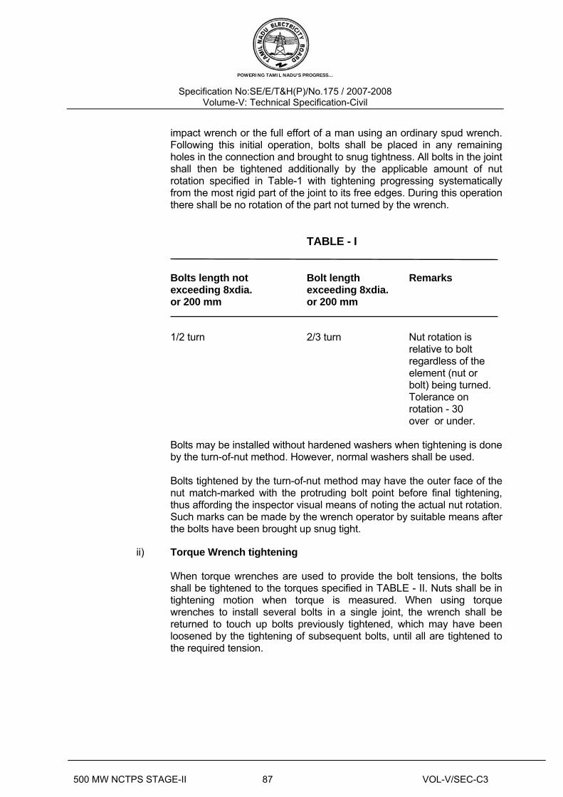
impact wrench or the full effort of a man using an ordinary spud wrench. Following this initial operation, bolts shall be placed in any remaining holes in the connection and brought to snug tightness. All bolts in the joint shall then be tightened additionally by the applicable amount of nut rotation specified in Table-1 with tightening progressing systematically from the most rigid part of the joint to its free edges. During this operation there shall be no rotation of the part not turned by the wrench.
TABLE - I Bolts length not Bolt length Remarks exceeding 8xdia. exceeding 8xdia. or 200 mm or 200 mm 1/2 turn 2/3 turn Nut rotation is relative to bolt regardless of the element (nut or bolt) being turned. Tolerance on rotation - 30 over or under. Bolts may be installed without hardened washers when tightening is done
by the turn-of-nut method. However, normal washers shall be used. Bolts tightened by the turn-of-nut method may have the outer face of the
nut match-marked with the protruding bolt point before final tightening, thus affording the inspector visual means of noting the actual nut rotation. Such marks can be made by the wrench operator by suitable means after the bolts have been brought up snug tight.
ii) Torque Wrench tightening When torque wrenches are used to provide the bolt tensions, the bolts
shall be tightened to the torques specified in TABLE - II. Nuts shall be in tightening motion when torque is measured. When using torque wrenches to install several bolts in a single joint, the wrench shall be returned to touch up bolts previously tightened, which may have been loosened by the tightening of subsequent bolts, until all are tightened to the required tension.
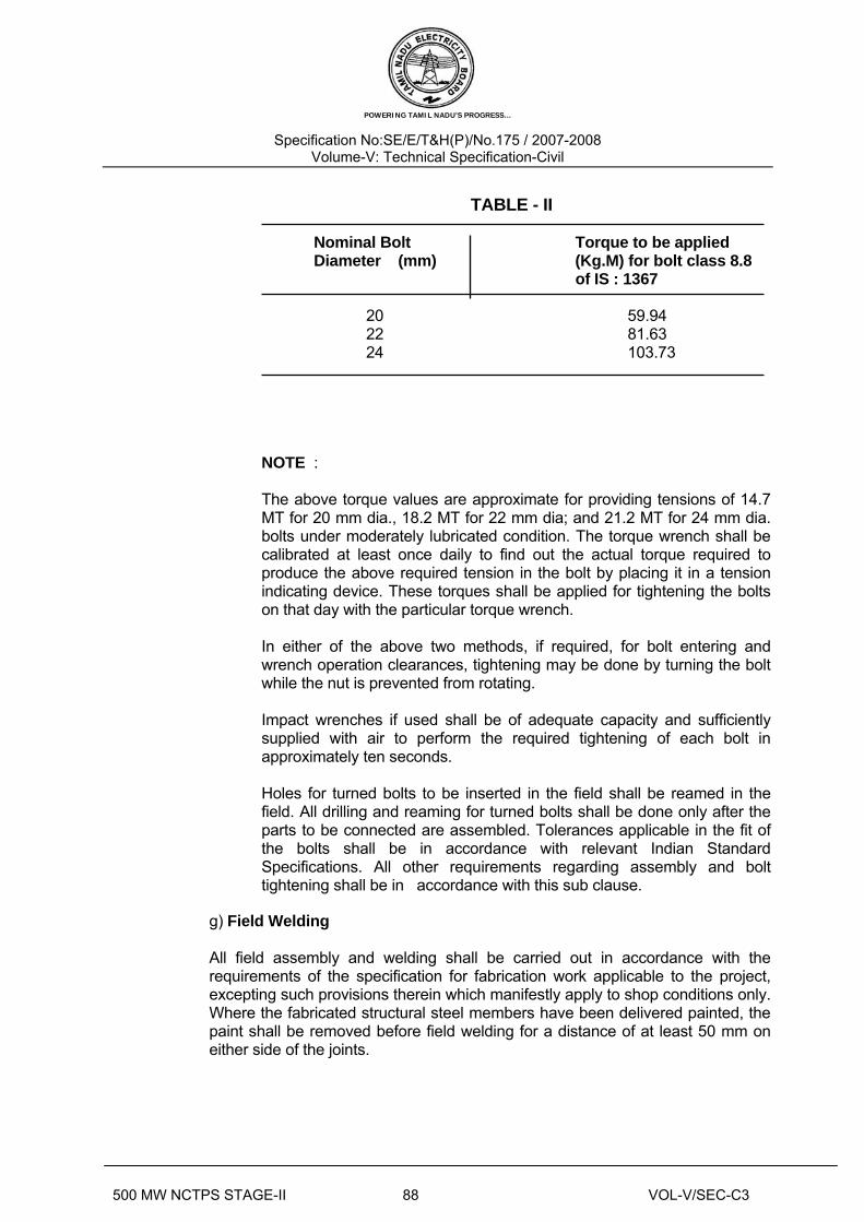
POWERING TAMIL NADU’S PROGRESS…
Specification No:SE/E/T&H(P)/No.175 / 2007-2008 Volume-V: Technical Specification-Civil
500 MW NCTPS STAGE-II 88 VOL-V/SEC-C3
TABLE - II Nominal Bolt Torque to be applied Diameter (mm) (Kg.M) for bolt class 8.8 of IS : 1367 20 59.94 22 81.63 24 103.73 NOTE : The above torque values are approximate for providing tensions of 14.7
MT for 20 mm dia., 18.2 MT for 22 mm dia; and 21.2 MT for 24 mm dia. bolts under moderately lubricated condition. The torque wrench shall be calibrated at least once daily to find out the actual torque required to produce the above required tension in the bolt by placing it in a tension indicating device. These torques shall be applied for tightening the bolts on that day with the particular torque wrench.
In either of the above two methods, if required, for bolt entering and
wrench operation clearances, tightening may be done by turning the bolt while the nut is prevented from rotating.
Impact wrenches if used shall be of adequate capacity and sufficiently
supplied with air to perform the required tightening of each bolt in approximately ten seconds.
Holes for turned bolts to be inserted in the field shall be reamed in the
field. All drilling and reaming for turned bolts shall be done only after the parts to be connected are assembled. Tolerances applicable in the fit of the bolts shall be in accordance with relevant Indian Standard Specifications. All other requirements regarding assembly and bolt tightening shall be in accordance with this sub clause.
g) Field Welding All field assembly and welding shall be carried out in accordance with the
requirements of the specification for fabrication work applicable to the project, excepting such provisions therein which manifestly apply to shop conditions only. Where the fabricated structural steel members have been delivered painted, the paint shall be removed before field welding for a distance of at least 50 mm on either side of the joints.

POWERING TAMIL NADU’S PROGRESS…
Specification No:SE/E/T&H(P)/No.175 / 2007-2008 Volume-V: Technical Specification-Civil
500 MW NCTPS STAGE-II 89 VOL-V/SEC-C3
h) Holes, cutting and fitting No cutting of sections, flanges, webs, cleats, bolts, welds etc. shall be done
unless specifically approved and / or instructed by the Engineer. The erector shall not cut, drill or otherwise alter the work of other trades, or his
own work to accommodate other trades, unless such work is clearly specified in the Contract or directed by the Engineer. Wherever such work is specified the Contractor shall obtain complete information as to size, location and number of alterations prior to carrying out any work. The Contractor shall not be entitled for any payment on account of any such work.
5.03.02 Drifting Correction of minor misfits and reasonable amount of reaming and cutting of
excess stock from rivets will be considered as permissible. For this, light drifting may be used to draw holes together and drills shall be used to enlarge holes as necessary to make connections. Reaming, that weakens the member or makes it impossible to fill the holes properly or to adjust accurately after reaming shall not be allowed.
Any error in shop work which prevents the proper assembling and fitting of parts
by moderate use of drift pins and reamers shall immediately be called to the attention of the Engineer and approval of the method of correction obtained. The use of gas cutting torches at erection site is prohibited.
5.03.03 Grouting of stanchion bases and bearings of beams and girders on stone, brick or concrete (Plain or reinforced) Grouting shall be carried out with Ordinary Cement grout as described below : The mix shall be one (1) part cement and one (1) part sand and just enough
water to make it workable. The positions to be grouted shall be cleaned thoroughly with compressed air jet and wetted with water and any accumulated water shall be removed. These shall be placed under expert supervision, taking care to avoid air-locks. Edges shall be finished properly. If the thickness of grout is 25 mm or more, two (2) parts of 6 mm down graded stone chips may be added to the above noted cement-sand grout mix, if required, by the Engineer or shown on the drawings.
Admixtures like aluminium powder, "ironite" or equivalent may be required to be
added to the grout to enhance certain desirable properties of the grout. Alternatively, the grouting may be done with non-shrink high strength free flow
cementious grout (ready mixed) like "Sika grout - 214", or "Anchor NSG" or approved equivalent.
POWERING TAMIL NADU’S PROGRESS…
Specification No:SE/E/T&H(P)/No.175 / 2007-2008 Volume-V: Technical Specification-Civil
500 MW NCTPS STAGE-II 90 VOL-V/SEC-C3
No grouting shall be carried out until a sufficient number of bottom lengths of stanchions have been properly lined, leveled and plumbed and sufficient floor beams are tied in position.
Whatever method of grouting is employed, the operation shall not be carried out
until the steelwork has been finally leveled and plumbed, the stanchion bases being supported meanwhile by steel wedges, and immediately before grouting, the space under steel shall be thoroughly cleaned.
5.03.04 Painting after erection Field painting, if required to be done by the erection Contractor, shall only be
done after the structure is erected, leveled, plumbed, aligned and grouted in its final position, tested and accepted by the Engineer. However, touch up paintings, making good any damaged shop painting and completing any unfinished portion of the shop coat shall be carried out by the erection Contractor free of cost to the Owner. The materials and specification for such painting in the field shall be in accordance with the requirements of the specification for fabrication of structural steelwork applicable for the project.
Painting shall not be done in rainy or foggy weather or when humidity is such as
to cause condensation on the surfaces to be painted. Before painting of steel, which is delivered unpainted, is commenced, all surfaces to be painted shall be dried and thoroughly cleaned from all loose scale and rust.
All field bolts, welds and abrasions to the shop coat shall be spot painted with the
same paint used for the shop coat. Where specified, surfaces which will be in contact after site assembling shall receive a coat of paint (in addition to the shop coat, if any) and shall be brought together while the paint is still wet.
Surface which will be inaccessible after field assembly shall receive the full
specified protective treatment before assembly. Bolts and fabricated steel members which are galvanized or otherwise treated and steel members to be encased in concrete shall not be painted.
The specification for paint and workmanship shall be in accordance with the
requirements of the specification for fabrication of structural steelwork applicable to the project. The number of coats and the shades to be used shall be as specified or as directed by the Engineer.
5.03.05 Stainless Steel Plate Lining in Bunker Hopper The hopper portion of the coal bunkers shall be lined with stainless steel plates
of 3 to 6 mm thickness. The stainless steel shall be of AISI-316 quality. The work includes supply, fabrication, welding and fixing of stainless steel lining plate to bunker M.S. plate as per drawing & specification.
The stainless steel liner shall be fixed to the tanker hopper MS shall be plug
welding using special electrodes (such as, Inox-CW coding AWS-310-16, ISMBOS-311 or Inox-D2 coding AWSE-309-16, ISMB 04-311 manufactured by

POWERING TAMIL NADU’S PROGRESS…
Specification No:SE/E/T&H(P)/No.175 / 2007-2008 Volume-V: Technical Specification-Civil
500 MW NCTPS STAGE-II 91 VOL-V/SEC-C3
Advani Oerlikon Ltd. or equivalent). Such plug welding shall be done by drilling 21.5 mm dia. holes at 300 mm centre to centre both ways as per drawings. The plug welding shall be ground flush with the lining plate.
5.03.06 Final cleaning up Upon completion of erection and before final acceptance of the work by the
Engineer, the Contractor shall remove free of cost all false work, rubbish and all Temporary Works resulting in connection with the performance of his work.
5.03.07 Safety Measures during Erection The safety measures to workmen and supervisors during all types of erection
work (e.g., use of lifting appliances, slingning, welding, gas cutting, etc.) should be taken as per IS : 7205. When any statutory provisions exist, the same shall be complied with in addition to the provisions contained in the above code.
5.04.00 TESTING AND ACCEPTANCE CRITERIA 5.04.01 General Loading tests shall be carried out on erected structures, if required by the
Engineer, to check adequacy of fabrication and/or erection. Any structure or a part thereof found to be unsuitable for acceptance as a result of the test shall have to be dismantled and replaced with suitable member as per the Contract of either fabrication or erection of steelwork whoever is responsible for it and no payment towards the cost of the dismantled portion and any connected work shall be made to the Contractor, unless it is proved that the deficiency is due to reasons beyond the Contractor's scope. On the basis of the tests, the Engineer will decide whether the fabricator or the erector is responsible for the unacceptable member or structure and his decision will be final. In case it is established that the unacceptability of the member or structure is due to design deficiency, the cost of replacement and/or modifications will be borne by the Owner. In course of dismantling, if any damage is done to any other parts of the structure or to any fixtures, the same shall be made good free of cost by the Contractor responsible, to the satisfaction of the Engineer. The cost of the tests specified hereinafter shall be borne by the Owner. Any extra claim due to loss of time, idle labour, etc. arising out of these testing operations shall not be entertained, however, only reasonable and appropriate time extensions will be allowed.
The structure or structural member under consideration shall be loaded with its
actual dead load for as long a time as possible before testing and the tests shall be conducted as indicated in the following Sub-clauses 4.1.1, 4.1.2 and 4.1.3. The method of testing and application of loading shall be as approved by the Engineer.

POWERING TAMIL NADU’S PROGRESS…
Specification No:SE/E/T&H(P)/No.175 / 2007-2008 Volume-V: Technical Specification-Civil
500 MW NCTPS STAGE-II 92 VOL-V/SEC-C3
a) Stiffness Test In this test, the structure or member shall be subjected, in addition to its actual
dead load, to a test load equal to 1.5 times the specified superimposed load, and this loading shall be maintained for 24 hours. The maximum deflection attained during the test shall be within the permissible limit. If, after removal of the test load, the member or structure does not show a recovery of at least 80 per cent of the maximum strain or deflection shown during 24 hours under load, the test shall be repeated. The structure or member shall be considered to have sufficient stiffness, provided that the recovery after this second test is not less than 90 per cent of the maximum increase in strain or deflection recorded during the second test.
b) Strength Test The structure or structural member under consideration shall be subjected, in
addition to its actual dead load, to a test load equal to the sum of the dead load and twice the specified superimposed load, and this load shall be maintained for 24 hours.
In the case of wind load, a load corresponding to twice the specified wind load
shall be applied and maintained for 24 hours, either with or without the vertical test load for more severe condition in the member under consideration or the structure as a whole. Complete tests under both conditions may be necessary to verify the strength of the structure. The structure shall be deemed to have adequate strength if, during the test, no part fails and if on removal of the test load, the structure shows a recovery of at least 20 per cent of the maximum deflection or strain recorded during the 24 hours under load.
c) Structure of same design Where several structures are built to the same design and it is considered
unnecessary to test all of them, one structure, as a prototype, shall be fully tested, as described in previous Sub-clauses, but in addition, during the first application of the test load, particular note shall be taken of the strain or deflection when the test load 1.5 times the specified superimposed load has been maintained for 24 hours. This information is required as a basis of comparison in any check test carried out on samples of the structure.
When a structure of the same type is selected for a check test, it shall be
subjected, in addition to its actual dead load, to a superimposed test load, equal to 1.5 time the specified live load, in a manner and to an extent prescribed by the Engineer. This load shall be maintained for 24 hours, during which time, the maximum deflection shall be recorded. The check test shall be considered satisfactory, provided that the maximum strain or deflection recorded in the check test does not exceed by more than 20% of the maximum strain or deflection recorded at similar load in the test on the prototype.
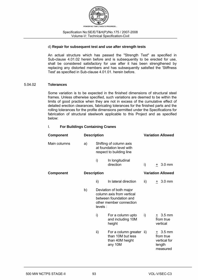
POWERING TAMIL NADU’S PROGRESS…
Specification No:SE/E/T&H(P)/No.175 / 2007-2008 Volume-V: Technical Specification-Civil
500 MW NCTPS STAGE-II 93 VOL-V/SEC-C3
d) Repair for subsequent test and use after strength tests An actual structure which has passed the "Strength Test" as specified in
Sub-clause 4.01.02 herein before and is subsequently to be erected for use, shall be considered satisfactory for use after it has been strengthened by replacing any distorted members and has subsequently satisfied the 'Stiffness Test' as specified in Sub-clause 4.01.01. herein before.
5.04.02 Tolerances Some variation is to be expected in the finished dimensions of structural steel
frames. Unless otherwise specified, such variations are deemed to be within the limits of good practice when they are not in excess of the cumulative effect of detailed erection clearances, fabricating tolerances for the finished parts and the rolling tolerances for the profile dimensions permitted under the Specifications for fabrication of structural steelwork applicable to this Project and as specified below:
I. For Buildings Containing Cranes Component Description Variation Allowed Main columns a) Shifting of column axis at foundation level with respect to building line i) In longitudinal direction i) +_ 3.0 mm Component Description Variation Allowed ii) In lateral direction ii) +_ 3.0 mm b) Deviation of both major column axis from vertical between foundation and other member connection levels : i) For a column upto i) +_ 3.5 mm
and including 10M from true height vertical ii) For a column greater ii) +_ 3.5 mm than 10M but less from true than 40M height vertical for any 10M length measured

POWERING TAMIL NADU’S PROGRESS…
Specification No:SE/E/T&H(P)/No.175 / 2007-2008 Volume-V: Technical Specification-Civil
500 MW NCTPS STAGE-II 94 VOL-V/SEC-C3
between conn- ection levels,
but not more than +_ 7.0 mm per 30 m length
c) For adjacent pairs of columns across the width of the building prior to +_ 9 mm on true placing of truss. span. d) For any individual column deviation of any bearing or resting level from levels shown on drawings. +_ 3.0 mm e) For adjacent pairs of columns either across the width of building or longitudinally level difference allowed between bearing or seating level supposed to be at the same level. 3 mm Trusses a) Deviation at centre of 1/1500 of the span of upper chord span or not member from vertical plane greater than running through centre 10 mm which-
of bottom chord ever is the least Component Description Variation Allowed b) Lateral displacement of 1/250 of depth top chord at centre of of truss or span from vertical plane 20 mm which- running through centre ever is the least of supports. Crane a) Difference in levels of Girders & crane rail measured bet- Tracks ween adjacent columns. 2.0 mm b) Deviation to crane rail gauge +_ 3.0 mm c) Relative shifting of ends of adjacent crane rail in plan and elevation after thermit welding. 1.0 mm

POWERING TAMIL NADU’S PROGRESS…
Specification No:SE/E/T&H(P)/No.175 / 2007-2008 Volume-V: Technical Specification-Civil
500 MW NCTPS STAGE-II 95 VOL-V/SEC-C3
d) Deviation of crane rail axis from centre line of Web. +_ 3.5 mm Setting of At the time of setting of Expansion the expansion gaps, due gaps regard shall be taken of the ambient temperature above or below 30oC. The coefficient of expan- sion or contraction shall be taken as 0.000012 per Deg. C per unit length. II. For Building without Cranes The maximum tolerances for line and level of the steel work shall be ±
3.0 mm on any part of the structure. The structure shall not be out of plumb more than 3.5 mm on each 10M section of height and not more than 7.0 mm per 30 M section.
These tolerances shall apply to all parts of the structure unless the
drawings issued for erection purposes state otherwise. 5.04.03 Acceptance Structures and members which have passed the tests and conform to all
requirements specified in the foregoing Sub-clause 4.01.00, 4.01.01, 4.01.02, 4.01.03 and 4.01.04 and other applicable provisions of this Specification and are within the limits of tolerances specified in Sub-clause 4.02.00 and/or otherwise approved by the Engineer shall be treated as approved and accepted for the purpose of fulfilment of the provisions of this Contract.
5.05.00 INFORMATION TO BE SUBMITTED 5.05.01 Before Tender Along with the Tenders the Tenderers will be required to submit the following
information : a) Tentative Programme The Tenderer shall submit a tentative programme based on the information
available in the Tender Document and visit to Site indicating the structure-wise erection schedule proposed to be maintained by the Contractor to complete the job in time in accordance with the Contract.

POWERING TAMIL NADU’S PROGRESS…
Specification No:SE/E/T&H(P)/No.175 / 2007-2008 Volume-V: Technical Specification-Civil
500 MW NCTPS STAGE-II 96 VOL-V/SEC-C3
b) Constructional Plant and Equipment, Tools, Temporary Works & Manpower A detailed list of all Constructional Plant & Equipment like cranes, derricks,
winches, welding sets, erection tools etc. along with their make, model, present condition and location available with the Tenderer which he will be able to employ on the job to maintain the progress of work in accordance with the Contract shall be submitted along with the Tender. The total number of each category of experienced personnel like fitters, welders, riggers etc. that he will be able to employ on the job shall also be indicated.
c) Erection yard A site plan showing the layout and location of the erection yard proposed to be
established by the Tenderer shall be attached with the Tender indicating the storage space for fabricated steel materials, site-fabrication and repair shop, covered stores, offices, locations of erection equipments and other facilities. The Engineer shall have the right to modify the arrangement and location of the proposed yard to suit site conditions and the Contractor shall comply with the same without any claim whatsoever.
5.05.02 After award of the Contract After award of the contract, the Contractor shall submit the following: a) Detailed Programme The Contractor shall submit a detailed erection programme within a month of
the award of the Contract for completion of the work in time in accordance with the Contract. This will show the target programme, with details of erection proposed to be carried out in each fortnight, details of major equipment required and an assessment of required strength of various categories of workers in a proforma approved by the Engineer.
b) Weekly Progress Report The Contractor shall submit weekly progress reports in triplicate to the Engineer
showing along with necessary photographs, 125 mm x 90 mm size, and all details of actual achievements against the target programme specified in Sub- clause 5.02.01 above. Any shortfall in the achievement in a particular week must be made up within the next week. Along with this report, the Contractor shall also furnish details of fabricated materials in hand at site and the strength of his workers.

POWERING TAMIL NADU’S PROGRESS…
Specification No:SE/E/T&H(P)/No.175 / 2007-2008 Volume-V: Technical Specification-Civil
500 MW NCTPS STAGE-II 140 VOL-V/SEC-C3
Soil And Waste Pipeline On completion of laying, the cast iron soil, waste and ventilation pipelines shall be
tested by the Contractor to detect leakage and any other defects in the pipelines. Test shall be conducted using proper apparatus with attachment for smoke
making machine for applying smoke to the pipelines under pressure. Only cotton waste or brown paper soaked in creosote oil shall be used and fired to obtain dense and pungent smoke. While conducting smoke test, top of soil, waste and ventilation pipes shall be kept open till smoke starts coming out of the openings. The openings shall then be securely plugged with expanding rubber or any other approved plug. The floor traps and other openings for connecting sanitary fixtures shall be sealed with water or other approved plug. The entire pipeline shall be tested in suitable sections as directed by the Consultant. The entire length of the pipelines including all joints under test shall be closely observed for any sign of smoke leakage.
Galvanised Steel Water Supply Pipes After the laying and fixing of all galvanised steel water supply pipes and fittings
are completed, the line shall be slowly and carefully charged with water to a test pressure of 5 kg per sq. cm or the specified working pressure plus 50%, as may be prescribed by the Consultant. Care shall be taken that air in pipelines is completely exhausted while filling the pipelines with water. This pressure shall be maintained for at least one hour, unless otherwise specified.
10 METAL WORK 10.1 General This chapter covers the various metal works such as, Rolling shutter, grills, steel
doors, aluminium doors and windows, ventilators, Louvers, suspended ceilings, roof and wall cladding etc.
10.2 Standards Unless otherwise specified herein. The following standards shall apply to the
works covered by this chapter. IS:733 Wrought aluminium and aluminium alloy bars, rods and
sections (for general engineering purposes) IS:737 Wrought aluminium and aluminium alloy sheet and strips
for general engineering purposes. IS:1038 Steel doors, windows and ventilators IS:1361 Steel windows for industrial buildings IS:1948 Aluminium doors, windows and ventilators IS:1949 Aluminium windows for industrial buildings. IS:3614 Specification for fire check doors IS:4351 Specification for steel door frames IS:6051 Code for designation of aluminium and its alloys. Rolling Shutters IS:2108 Blackheart malleable iron castings
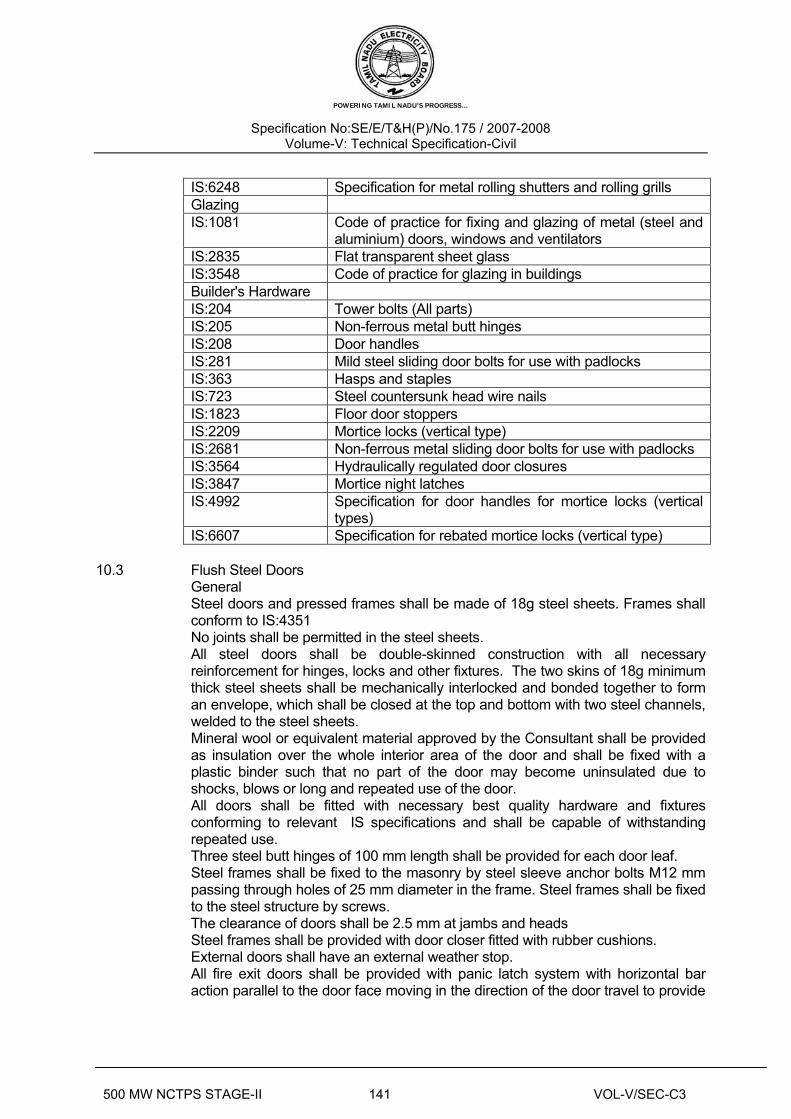
POWERING TAMIL NADU’S PROGRESS…
Specification No:SE/E/T&H(P)/No.175 / 2007-2008 Volume-V: Technical Specification-Civil
500 MW NCTPS STAGE-II 141 VOL-V/SEC-C3
IS:6248 Specification for metal rolling shutters and rolling grills Glazing IS:1081 Code of practice for fixing and glazing of metal (steel and
aluminium) doors, windows and ventilators IS:2835 Flat transparent sheet glass IS:3548 Code of practice for glazing in buildings Builder's Hardware IS:204 Tower bolts (All parts) IS:205 Non-ferrous metal butt hinges IS:208 Door handles IS:281 Mild steel sliding door bolts for use with padlocks IS:363 Hasps and staples IS:723 Steel countersunk head wire nails IS:1823 Floor door stoppers IS:2209 Mortice locks (vertical type) IS:2681 Non-ferrous metal sliding door bolts for use with padlocks IS:3564 Hydraulically regulated door closures IS:3847 Mortice night latches IS:4992 Specification for door handles for mortice locks (vertical
types) IS:6607 Specification for rebated mortice locks (vertical type)
10.3 Flush Steel Doors General Steel doors and pressed frames shall be made of 18g steel sheets. Frames shall
conform to IS:4351 No joints shall be permitted in the steel sheets. All steel doors shall be double-skinned construction with all necessary
reinforcement for hinges, locks and other fixtures. The two skins of 18g minimum thick steel sheets shall be mechanically interlocked and bonded together to form an envelope, which shall be closed at the top and bottom with two steel channels, welded to the steel sheets.
Mineral wool or equivalent material approved by the Consultant shall be provided as insulation over the whole interior area of the door and shall be fixed with a plastic binder such that no part of the door may become uninsulated due to shocks, blows or long and repeated use of the door.
All doors shall be fitted with necessary best quality hardware and fixtures conforming to relevant IS specifications and shall be capable of withstanding repeated use.
Three steel butt hinges of 100 mm length shall be provided for each door leaf. Steel frames shall be fixed to the masonry by steel sleeve anchor bolts M12 mm
passing through holes of 25 mm diameter in the frame. Steel frames shall be fixed to the steel structure by screws.
The clearance of doors shall be 2.5 mm at jambs and heads Steel frames shall be provided with door closer fitted with rubber cushions. External doors shall have an external weather stop. All fire exit doors shall be provided with panic latch system with horizontal bar
action parallel to the door face moving in the direction of the door travel to provide

POWERING TAMIL NADU’S PROGRESS…
Specification No:SE/E/T&H(P)/No.175 / 2007-2008 Volume-V: Technical Specification-Civil
500 MW NCTPS STAGE-II 142 VOL-V/SEC-C3
immediate exit in the event of fire or emergency whilst providing security against unauthorised entry.
Sign plates of anodised aluminium or galvanised steel shall be screwed to the door under the horizontal bar, on which the sign, “PUSH BAR TO OPEN" shall he printed.
The thickness of the normal steel door shall be 45 mm for both single and double doors.
All the above specified details shall be applied for normal steel doors, fire resistant steel doors and fire proof steel doors.
The contractor shall provide the Consultant with following documents for the steel doors:
• Detailed shop and construction drawings as well as the door schedules and samples of hardware.
• Detailed structural analysis of the proposed supplies. • Test certificates proving conformity of the physical properties stipulated in
this specification and relevant standards 10.4 Fire Resisting And Fire Proof Doors Fireproof doors with panic devices shall be provided at all fire exit points as per
recommendations of Tariff Advisory Committee (TAC). These shall conform to IS:3614 (Part I and Part II). Fire rating of doors shall be as per TAC requirement. However, minimum requirement shall be for two hours. Type of doors shall be double cover-plated type with mineral wool insulation.
10.5 Rolling Shutter (Hand Operated, Mechanical Gear Operated And Electrically
Operated) and Grills Rolling shutters shall be fabricated from 18 gauge steel and machine rolled with
75 mm rolling centres with effective bridge depth of 12 mm lath sections, interlocked with each other and ends locked with malleable cast iron clips to IS:2108. They shall be designed to withstand a wind load of 200 Kg/m2 without excessive deflection.
The guides shall be either rolled or pressed deep channel sections 75 mm and 25 mm wide fitted with necessary fitting and fixtures. The suspension shaft shall be formed from heavy duty tubes conforming to IS:1161 and of sufficient diameter so as to resist deflection due to weight of the rolling shutter. The deflection shall not exceed 5mm / metre width. The shaft shall be provided with Cl pulleys and helical springs for counter balancing the weight of the shutter adequately.
The springs shall be approved high tensile flat springs conforming to Grade 2 of IS:4454. These shall be fitted inside the fabricated housing at either ends, which counter-balance the shutter curtain.
The ball bearings shall be double row self-aligning ball bearings fitted inside CI housing fixed on side brackets holding the suspension shaft at either end. The roller assembly shall be designed so as to be capable of producing sufficient torque to ensure easy operation of the rolling shutter in any position. The spring tension shall be adjustable by means of suitable adjustment holes drilled on the rims of the pulley.
The hood cover shall be made of 20 gauge sheets with necessary stiffeners and framework to prevent sag. The bottom lock plate shall be made of 5 mm thick

POWERING TAMIL NADU’S PROGRESS…
Specification No:SE/E/T&H(P)/No.175 / 2007-2008 Volume-V: Technical Specification-Civil
500 MW NCTPS STAGE-II 143 VOL-V/SEC-C3
M.S. plate and 95 mm wide, reinforced with angle/T iron of suitable section with 6 mm dia M.S. rivets interlocked with last stride of curtain.
The locking arrangement shall consist of sliding bolts at both ends of the bottom plate fitted to engage with suitable receiving pockets at the bottom of guide channels.
Unless otherwise specified, for overall area of rolling shutters up to 9 sq.m, pull and push type hand-operated shutters shall be used. For area between 9 and 12 sq.m, pull and push type shutters shall be provided with ball bearings. For area larger than 12 sq.m mechanical gear type or electrically operated shutters shall be supplied.
Rolling grills shall be constructed out of 6 mm dia. rods at 35 mm on centres
running horizontally flexible connected with vertical links spaced not more than 200 mm centres. Alternatively, rolling grills shall be made from perforated slats of approved design reinforced with 6 mm dia. rods.
10.6 Folding Steel Doors The folding doors shall be used for the entrance of machine halls, workshops and
similar. The unit shall be manufactured as a top hung folding door of edged steel sheets and steel sections. Clear height of the pass-gate shall be not less than 2.00 m.
Door leaves shall be manufactured with double flush skin of steel sheet, min 1.5 mm thick, edged and welded to the case. The case shall be stiffened with steel section frame. Thickness of the leaves shall not be less 60 mm.
The door shall be constructed for one way normal manual usage under subtropical conditions for exterior openings in accordance with the architectural design.
The insulation material inside the door shall be fire resistant. The fixing of the door frame to the wall or steel structure shall be carried out by
means of flat steel anchors, size not less than 250/40/4 mm and steel bolts, dia. 8 mm, either cemented into the wall or screwed to the steel structure.
Three anchors shall be provided per 2.5 m length with a minimum of six (6) anchors per door frame.
Joints between doorframe and construction shall be sealed with permanent elastic compound where the door has to be fixed to steel structure.
The door shall be furnished with heavy sturdy-built hardware of corrosion protected steel consisting of: • truck brackets • intermediate hinges with nylon washers • hangers with nylon wheels, ball bearing, lubricated for life incl. wheel centre
pattern • flush handles outside • fold-aside butt hinges, min. three (3) per 2.5 m length • door guides with end and centre pattern • floor channel • furniture, bolts and screws with all fittings
The door and frame shall be galvanised and coated by epoxy paint over galvanizing.

POWERING TAMIL NADU’S PROGRESS…
Specification No:SE/E/T&H(P)/No.175 / 2007-2008 Volume-V: Technical Specification-Civil
500 MW NCTPS STAGE-II 144 VOL-V/SEC-C3
10.7 Steel Windows and Ventilators
These shall conform in all respects to IS: 1038, IS:7452 and IS: 1361 latest editions and as shown on drawings. The details as called for in the above codes shall be applicable for coupling mullions, transoms, weather bars, pivot arrangements for ventilators, etc. or as shown on drawings or called for in the Schedule of Items.
All welds shall be dressed flush on all exposed and contact surfaces.
Where composite unit openings are shown on drawings, the individual window
units shall be joined together with requisite transoms and mullions as shown on drawings. All windows shall be outside glazed fixed with putty or metal glazing beads as shown on the drawings and/or specified under Schedule of Items. Where aluminium glazing beads are specified they shall be extruded aluminium channel 9.5 mm x 9.5 mm x 1.6 mm (Indal Section No. 2209) unless otherwise shown on drawings. Aluminium beads shall be given one coat of zinc chromate primer before fixing to windows.
10.8 Aluminium Doors, Windows, Glass Walls and Louvers Aluminium sections for doors, windows and glass walls shall comply with IS:1948
and IS:1949. Aluminium doors, windows and glass walls as well as aluminium frames shall be
anodised in accordance with relevant Indian Standards. All hardware shall be of concealed construction in the aluminium frame and shall
be made of stainless steel. Sections of aluminium profiles shall not be less than 50 mm deep.
All doors shall be provided with door closer, door stops. Aluminium alloys shall be of uniform quality, free from defects impairing strength
and durability with regularity of surfaces and accuracy of right angles. Aluminium windows at high levels shall be fitted with mechanical devices of type
approved by the Consultant to allow for opening of such windows from the ground level.
Marble sills of 30 mm thickness shall be installed under the windows. Door and window elements shall be fixed to the structure by means of separate
rectangular hollow galvanised steel or aluminium frame. Joints of door and window frames to the walls shall be covered with aluminium
angle on each side and they shall be sealed with permanent elastic material in accordance with the manufacturer’s instructions. For air-conditioned rooms, the aluminium windows shall have double glazing.
The Contractor shall provide the following documents for all aluminium profile constructions: • Detailed shop and construction drawings including the doors and windows
schedule • Detailed structural analysis of the proposed supplies • Test certificates proving the conformity of the physical properties stipulated in
the specifications and the relevant Standards stated herein

POWERING TAMIL NADU’S PROGRESS…
Specification No:SE/E/T&H(P)/No.175 / 2007-2008 Volume-V: Technical Specification-Civil
500 MW NCTPS STAGE-II 145 VOL-V/SEC-C3
10.9 Master Key System An appropriate serviceable and functional master key system for the whole plant
shall be installed. The elaboration of the system itself shall be made in close co-ordination with the Purchaser /Consultant and only after obtaining the Purchaser’s/Consultant’s approval in writing shall the order of production be placed.
The following requirements shall be met: • the general master key shall operate all locks • the main key shall open all locks of one building • the single key shall open the lock of a single room.
Necessary attention shall be paid to later extensions of the master key system, which shall be suitable for the entire plant including all final stages.
The profile cylinders shall be sea water resistant and shall suit all plant requirements. The material of the cylinders shall be of massive brass, nickel-plated with six security pawl studs.
The keys shall be made of material approved by the Purchaser / Consultant and shall have an engraved indication of the applicable key system and the building or door number.
Keys shall be supplied in the following numbers: General master key 10 Main keys 10 nos. per each building Single keys 3 nos. per each door 10.10 Suspended Ceilings Suspended ceilings shall be provided for control rooms, offices, conference
rooms, corridors, etc. The panels shall be 0.8 mm thick, stove enamelled, aluminium sheets In general the size of the panels shall be 600 mm x 600 mm. Panels of closed
appearance of 75 mm or 150 mm wide and length up to 6 meters could be used as directed by the Purchaser / Consultant.
The suspension system shall be of sufficient strength and rigidity to carry the panels.
The panels shall be supported by stove enamelled aluminium panel carriers. The rod hangers shall be made of galvanised steel of 4 mm diameter (minimum). The joints between the panels and the light fixtures and air supply ducts shall be
smooth and regular. Power driven fasteners shall be used for fixing the rod hangers in the reinforced
concrete ceiling. 10.11 Room Designation Signs The entrance to each room shall be furnished with a room designation sign on an
anodised aluminium plate of 4mm thickness Four horizontal grooves of 10 mm width at the lower end of the sign plate shall
take plastic strips on which the designation will be printed in English language. At the upper portion the room number shall be engraved with a black background.
The designation sign plates shall be screwed to the wall with non-corroding screws.
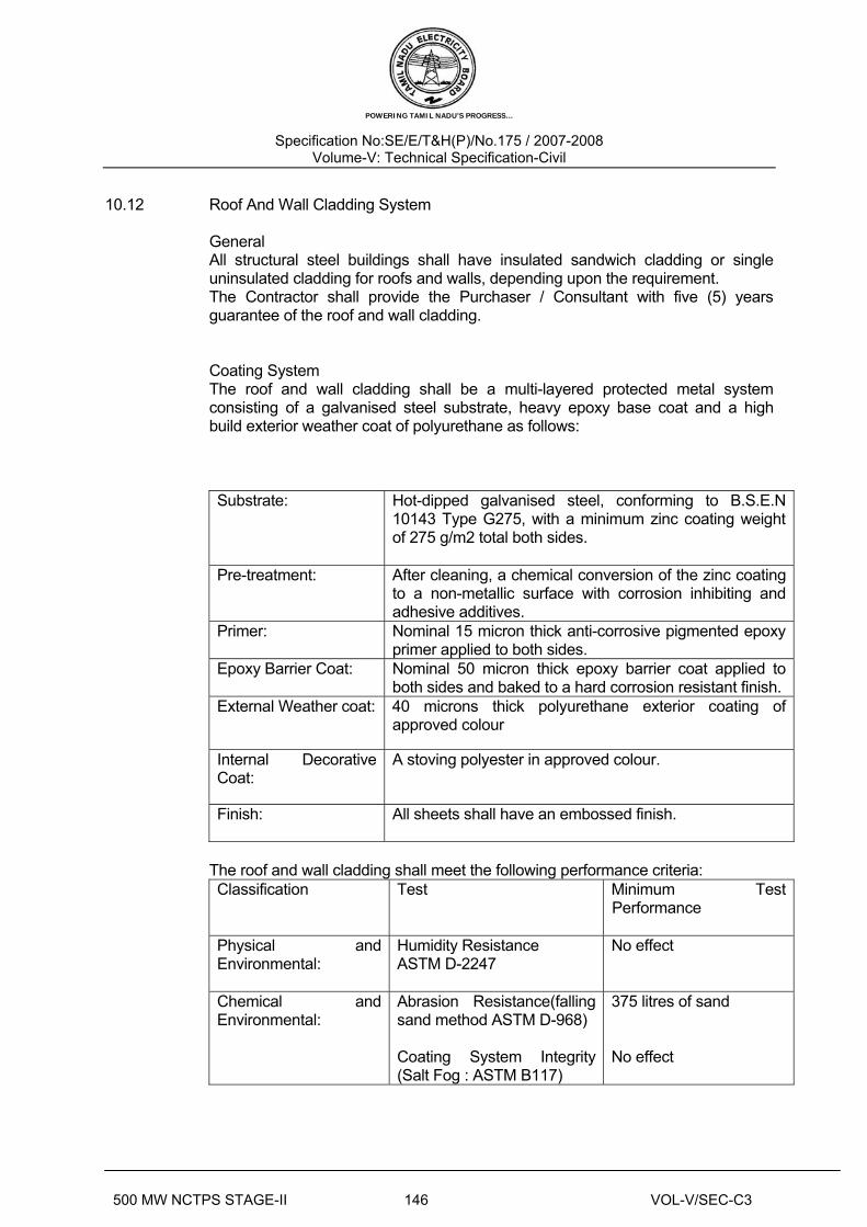
POWERING TAMIL NADU’S PROGRESS…
Specification No:SE/E/T&H(P)/No.175 / 2007-2008 Volume-V: Technical Specification-Civil
500 MW NCTPS STAGE-II 146 VOL-V/SEC-C3
10.12 Roof And Wall Cladding System General All structural steel buildings shall have insulated sandwich cladding or single
uninsulated cladding for roofs and walls, depending upon the requirement. The Contractor shall provide the Purchaser / Consultant with five (5) years
guarantee of the roof and wall cladding. Coating System The roof and wall cladding shall be a multi-layered protected metal system
consisting of a galvanised steel substrate, heavy epoxy base coat and a high build exterior weather coat of polyurethane as follows:
Substrate: Hot-dipped galvanised steel, conforming to B.S.E.N 10143 Type G275, with a minimum zinc coating weight of 275 g/m2 total both sides.
Pre-treatment: After cleaning, a chemical conversion of the zinc coating to a non-metallic surface with corrosion inhibiting and adhesive additives.
Primer: Nominal 15 micron thick anti-corrosive pigmented epoxy primer applied to both sides.
Epoxy Barrier Coat: Nominal 50 micron thick epoxy barrier coat applied to both sides and baked to a hard corrosion resistant finish.
External Weather coat: 40 microns thick polyurethane exterior coating of approved colour
Internal Decorative Coat:
A stoving polyester in approved colour.
Finish: All sheets shall have an embossed finish.
The roof and wall cladding shall meet the following performance criteria:
Classification Test Minimum Test Performance
Physical and Environmental:
Humidity Resistance ASTM D-2247
No effect
Chemical and Environmental:
Abrasion Resistance(falling sand method ASTM D-968) Coating System Integrity (Salt Fog : ASTM B117)
375 litres of sand No effect

POWERING TAMIL NADU’S PROGRESS…
Specification No:SE/E/T&H(P)/No.175 / 2007-2008 Volume-V: Technical Specification-Civil
500 MW NCTPS STAGE-II 147 VOL-V/SEC-C3
The above performance criteria shall be substantiated by test results certified by recognised independent testing authority.
Insulated Sandwich Cladding The insulated roof and wall cladding shall be formed from trapezoidal sheeting
and shall meet all specified design criteria. Roofs
External Roof Weather Sheet
: Profile Thickness Depth
: Trapezoidal : 0.70 mm : 38 mm
Internal Roof Sheet
: Profile Thickness Depth
: Trapezoidal : 0.95 mm : 61 mm
Loadings : The cladding system shall be suitable for the loadings and shall meet the following criteria Deflection : Roof area 1/200 of span, except where roof slopes are
below 5 degrees when the limiting deflection shall be 1/300 of the span
Walls
External wall Weather sheet
: Profile Thickness Depth
: Trapezoidal : 0.70 mm : 38 mm
Internal Wall Sheet
: Profile Thickness Depth
: Trapezoidal : 0.95 mm : 61 mm
The internal liner shall be formed from a trapezoidal galvanised sheet; the exposed face shall be painted.
Deflection : Wall area – 1/120 of the span.
Subgirts : 1.5 mm thick ‘Z’ type galvanised subgirts shall be employed to create a space to accommodate the specified thickness of the insulation. The location of the subgirts shall be such that the external weathering sheets shall meet the specified design loads.
The male side lap joints shall be sealed on site with suitable preformed mastic sealant.
Insulation : Mineral wool lightweight rolls conforming to the requirements of IS 8183 shall be fitted into the space created by the subgirts.
Thickness : 80 mm
Density : 24 kg/m3
Thermal Conductivity
: 0.40 w/m2K
Acoustic Requirements Of The Roof And Wall Cladding Constructions The roof and wall cladding shall provide an acoustic attenuation factor through the
construction of at least between R’w = 36 - 40 dB

POWERING TAMIL NADU’S PROGRESS…
Specification No:SE/E/T&H(P)/No.175 / 2007-2008 Volume-V: Technical Specification-Civil
500 MW NCTPS STAGE-II 148 VOL-V/SEC-C3
Translucent Sheeting Translucent sheeting shall be provided where required and fixed to the walls,
located in continuous bands, comprising of two skins translucent sheeting supplied to match and overlap the specified external and internal profiled metal cladding and manufactured as follows:
Polyester resin reinforced with chopped-strand glass fibre mat and made in a continuous process generally in accordance with IS Standards. A film of tedlar polyvinyl flouride or melinex polyester is bonded chemically to the external weathering surface. Flashing and accessories to be provided.
Light transmission: approx. 60-65% for clear skins End Laps External weathering sheet: Where the angles of the roofs are 7 degrees or below, the end laps shall be a
minimum of 200 mm. On roof slopes in excess of 7 degrees, the end laps shall be a minimum of 150 mm.
On vertical areas the end laps shall be a minimum of 100 mm. Internal liners: End laps shall be 75 mm on the trapezoidal internal liners; the tray shall be butt-
jointed. Sealant The cladding shall be sealed with a non-drying, non-corrosive permanently elastic
pre-formed metal sealing tape capable of performing in a temperature up to 1000oC.
Fixings The external weathering sheet shall be secured to the galvanised subgirts or
structural supports with stainless steel hexagon headed self-tapping screws, each with a integral EPDM (Ethylene Propalene Die Memonoma) washer bonded to a dished aluminium washer. The internal liners shall be secured to the supporting steel structure with galvanised self-tapping screws. Galvanised subgirts dependant on their type shall be secured with galvanised self-tapping screws or rivets.
Side lap fixings shall be blind rivets. The cladding supplier shall submit calculations, which substantiate that his fixing
allowances will meet the design loads. Flashings Flashings required in connection with the external weathering skin shall be formed
from 0.70 mm thick material as specified for the roof and/or side wall cladding. Flashings required in connection with the internal liner shall be constructed from
0.70 mm thick galvanised steel having a painted finish on the exposed face. Corrugation Fillers Profiled filler pieces shall be provided at all terminal positions on the roof and side
wall areas. The fillers shall be of polyethylene foam and be immune to bird and insect attack.

POWERING TAMIL NADU’S PROGRESS…
Specification No:SE/E/T&H(P)/No.175 / 2007-2008 Volume-V: Technical Specification-Civil
500 MW NCTPS STAGE-II 149 VOL-V/SEC-C3
Gutters / Rainwater Pipes Design procedures shall be based on appropriate Indian Standards. The
materials shall be either aluminium or zinc of suitable gauge, and the appliances and components shall comply with the requirements of the applicable Indian Standards.
Single sheet uninsulated roof and wall cladding The roof and/or side wall uninsulated cladding shall be a trapezoidal profiled
metal sheeting, protected on both sides by a multi-layer coating system, and shall meet all specified design criteria.
Roof Sheeting :Thickness Depth
: 0.95 mm : 61 mm
Wall sheeting :Thickness Depth
: 0.70 mm : 38 mm
Loadings :The cladding system shall be suitable for the loadings and shall meet the following criteria
Deflection : Roof area 1/200 of span, except where roof slopes are
below 5 degrees when the limiting deflection shall be 1/300 of the span
Wall area 1/200 of the span
End laps : Where the angles of the roofs are 7 degrees or below the end laps, shall be a minimum of 200 mm. On roof slopes in excess of 7 degrees, the end laps shall be a minimum of 150 mm
On vertical areas the end laps shall be a minimum of 100 mm
Sealants : The cladding shall be sealed with a non-drying, non-corrosive permanently elastic preformed metal sealing tape capable of performing in a temperature up to 1000 deg C.
Fixings : The cladding shall be secured to the structural steel supports with stainless steel hexagon headed self-tapping screw. Each complete with an integral EPDM washer bonded to a dished aluminium washer.
Side lap fixings shall be blind rivets. The cladding supplier shall submit calculations which substantiate that his fixing allowances will meet the design loads.
Flashings : Shall be formed from 0.70 mm thick material as specified for the roof and/or side wall cladding.
Corrugation Closures
: Profiled filler pieces shall be provided at all terminal positions on the roof and side wall areas the fillers shall be of polyethylene foam and be immune to bird and insect attack.

POWERING TAMIL NADU’S PROGRESS…
Specification No:SE/E/T&H(P)/No.175 / 2007-2008 Volume-V: Technical Specification-Civil
500 MW NCTPS STAGE-II 150 VOL-V/SEC-C3
The roof and wall cladding shall be supplied from reputed manufacturer and suppliers subject to the Purchaser’s/Consultant’s prior approval.
11 MISCELLANEOUS METAL & ALLIED WORKS
11.01.00 Scope
This shall include supply, fabrication and erection of miscellaneous metal items of light nature in gates, grills, balcony and stair handrails particulars, structural mullions and transoms, ladders hangers masonry anchors, shelf angles, edge angles, inserts, pipe sleeves, stair nosing, anchor bolts, fasteners, etc. as shown on drawing or as instructed by the Owner. The above items shall be of fabricated or cast M.S/ Aluminium/ Brass, cast iron, M.S. and galvanised M.S. Sheets, aluminium sheets, expanded metal, wire mesh etc. as shown on drawings and/or described in the Schedule of Items.
11.02.00 Installation
11.02.01 Fabrication/Casting
a).General
All work shall be done according to approved shop drawings. All workmanship shall be equal to the best practice in modern structural or foundry shop.
b). Shop Connections
i) All shop connections shall be riveted or welded except when noted
otherwise on drawings.
ii) Welding of steel shall be done in accordance with the IS : 816. Use of
metal arc welding for general construction in Mild Steel.
iii) Welding of aluminium shall be done in accordance with IS: 2812, Arc
welding of Aluminium and Alloys, Special care shall be taken to grind
smooth all welded surface that shall remain exposed to view. Welds
shall be electrically continuous if so required by the Owner.
c).Shop Coat
Before leaving the shop, all metal work shall be thoroughly cleaned by effective means of all loose mill/ scale, rust and foreign matter. Except where encased in concrete, all steelwork shall be given one coat of approved metal protective paint, applied by brush thoroughly and evenly, well worked into joints and other open spaces. All paint shall be applied to dry surfaces. When specified in Schedule, steel work shall be galvanised or galvanized and painted with a coat of zinc chromate primer. Aluminium surfaces which shall come in contact with masonry

POWERING TAMIL NADU’S PROGRESS…
Specification No:SE/E/T&H(P)/No.175 / 2007-2008 Volume-V: Technical Specification-Civil
500 MW NCTPS STAGE-II 151 VOL-V/SEC-C3
shall be given one coat of zinc chromate primer.
11.02.02 Erection
a) Bracing
The Contractor shall provide all necessary temporary guys and braces to ensure alignment and stability of the members and to take care of all loads to which the structure may be subjected including erection of equipment and operation of the same.
b) Temporary Bolting-Up
As erection proceeds the Contractor shall plumb up and level all members and shall securely bolt up to take care of all dead load, wind load and erection stresses. Wherever piles of materials, erection equipment or other loads are carried during erection, proper provision shall be made to take care of the stresses resulting from the same.
c) Turned Bolt
For field connections where bolting is specified, holes for the turned bolts may be reamed in the field, if required. All drilling or reaming for turned bolts shall be done after the parts to be connected are assembled.
d) Welding
Where specified on drawings, welding shall be done in accordance with IS : 816 for steel and IS: 2812 for Aluminium and Alloys.
e) Cutting and Fitting
No cutting of sections, flanges, webs of angles shall be done without the approval of the Owner. Where indicated on the drawings, holes, cuttings, etc. shall be provided as required for installation, to the work by the other Contractors. No additional holes or cuttings, than those shown on drawings, shall be made without the approval of the Owner.
f) Drifting
Correction of minor misfits and a reasonable amount of reaming and cutting of excess stock from rivets may be permitted. For this, light drifting may be allowed to draw holes together. Twist drills shall be used to enlarge as necessary to make connections. Reaming that weakens the members or make it impossible to fill the holes properly or to adjust accurately after reaming shall not be allowed.
Any error in shop work which prevents the proper assembling and fitting of parts by moderate use of drift pins or a moderate amount or reaming and slight chipping and cutting shall immediately be called to the attention of the Owner and approval of the method of correction obtained. The use of cutting torches to enlarge or alter rivet holes shall not be permitted.
g) Grouting
All bearing plates, loose lintels and beams, etc. shall be set to proper grade and level by the Contractor and the Owner's approval obtained before proceeding with the grouting. Grouting shall be done in 1:1.5:3 or 1:1- 1/2:3 concrete with 6 mm down stone chips.

POWERING TAMIL NADU’S PROGRESS…
Specification No:SE/E/T&H(P)/No.175 / 2007-2008 Volume-V: Technical Specification-Civil
500 MW NCTPS STAGE-II 152 VOL-V/SEC-C3
h) Anchor Bolting
When shown on drawings, the miscellaneous metal items shall be fixed to concrete by case hardened and drawn carbonizing steel expander nut and bolt. The Contractor shall submit the manufacturer's literature showing the average pull out and average shear values for bolts of various sizes. The bolts shall be fixed strictly as per the manufacturer's instructions.
i) Pipe Joints
M.S. Pipes shall be joined by threaded sockets or by welding. Cast iron pipes shall be socket and spigot jointed and caulked with hemp and molten lead.
j) Spot Painting
All field rivets and bolts and also any serious abrasion to shop paint shall be spot painted with the same materials as used for the shop paint or equivalent.
k) Making Good
All cutting to concrete or masonry shall be made good to the satisfaction of the Owner.
11.03.00 Acceptance Criteria
a) All items shall be of correct shape, size, weight etc. shown on drawings and
schedule of items.
b) For installed items, the tolerances shall be follows :
i) Permissible deviation from straightness - 1 in 1000.
ii)Seats, stiffener connections etc. shall be as per approved drawings and shall not interfere with architectural clearances.
c) All castings shall be free from blow holes, cracks and other blemishes.
11.04.00 I.S. Codes
IS : 226 - Structural Steel (Standard Quality)
IS: 800 - Code of practice for use of structural steel in general building construction.
IS : 816 - Use of metal arc welding for general construction in mild steel.
IS : 2812 - ARC WELDING OF ALUMINIUM AND ALLOYS
IS : 3150 - HEXAGONAL WIRE NETTING IS:4948 - Welded steel wire fabric for general use. 12 JOINERY 12.1 General This chapter covers the joinery for permanent works i.e. excluding formwork,
shuttering and wood scaffolding.

POWERING TAMIL NADU’S PROGRESS…
Specification No:SE/E/T&H(P)/No.175 / 2007-2008 Volume-V: Technical Specification-Civil
500 MW NCTPS STAGE-II 182 VOL-V/SEC-C3
18 SHEET WORK IN ROOF AND SIDING
SCOPE
This specification covers the erection of asbestos, C.G.I., aluminium or
other sheet covering to roof and side walls at various elevations and the fabrication and/or installation of asbestos, C.G.I or aluminium gutters, flashings etc., as shown on drawings and schedule of items.
IS Codes The following are some of the important IS Codes relevant to this sections : IS : 3007 : Code of practice for laying of asbestos cement sheets IS : 2527 : Code of practice for fixing rain water gutters and down pipes
for roof drainage IS : 1626 : Specification for asbestos cement building pipes gutters and
fittings IS : 277 : Specification for galvanised steel sheets (plain and
corrugated) 18.01.00 Installation 18.02.00 Storage of Materials All materials shall be stored by the Contractor in proper way to prevent all
damage. If the materials are issued at site by the Owner, the Contractor shall at the time of issue, satisfy himself about the condition of issued sheets, gutters, etc. and no complaints shall be entertained later.
18.03.00 Workmanship The workmanship shall be according to best construction practice to give a
water tight finish to the satisfaction of the Owner fixing of gutters and down pipes shall be according to IS:2527.

POWERING TAMIL NADU’S PROGRESS…
Specification No:SE/E/T&H(P)/No.175 / 2007-2008 Volume-V: Technical Specification-Civil
500 MW NCTPS STAGE-II 183 VOL-V/SEC-C3
18.03.01 Asbestos Sheeting Asbestos sheets of profiles as stated in the Schedule of Items, shall be fixed
with minimum 150 mm end lap and side laps as per manufacturer's specification Hook bolts or J-bolts shall be 8 mm dia. at 305 centres 6 mm dia galvanised iron seam bolt and nut with G.I. flat washers and bitumen washers shall be used for stiching ridge cappings, corner pieces, ventilators, north light curves etc.
18.03.02 C.G.I. Sheeting and Aluminium Sheeting
Side laps shall be 2 corrugations for roof and one corrugation for side sheeting. End laps shall be minimum 150 mm for roof and 100 mm for side sheeting. In ridges and hips where plain sheets are used the end laps shall be minimum 100 mm. Holes in C.G.I sheets shall preferably be made on the ground the sheets should be placed on trestles and holes punched in the ridge of the corrugation from the outside inward for obtaining proper seating of limpet washets. Sheets shall be secured to sheet framing by 8 mm dia. galvanised iron hooks or J-bolts and maximum 305 mm apart. The length of the hook or J-bolts shall be to suit the sections of the bearers.
Sheets shall also be bolted at the ends at every third corrugation with 6 mm dia. galvanised iron seam bolts and G.I. flat washers and bituminous washers.
18.03.03 Fibre Glass Reinforced Plastic Sheeting This shall be of thickness and profile as mentioned in the Schedule of Item.
Colour and light transmittance shall be as mentioned in drawings and or schedules. Where used in conjunction with C.G.I. or asbestos sheeting the end and side laps and fixing device shall be same as used for general sheeting. Where used in lieu of glass, the fixing shall be by means of timber or metal glazing beads as mentioned in schedule of items. In all cases, the installation shall be completely watertight and able to withstand the designed wind-pressure as mentioned in Schedule.
18.03.04 Precoated metal sheeting for roof shall be of precoated cold rolled sheet of
total coated thickness (TCT) 0.58 to 0.68 mm of approved manufacturer. The sheet shall be metallic hot deep coated with an alloy of 55% aluminium, 43% zinc and 1.55 silicon coating mass shall be 150 gms/sq.m. sheet shall be fixed with fastening clip and self tapping fastener. Ridge for slope roof shall be of similar material and shall be fixed with necessary self tapping screws as per manufacturer details.
Thermally insulated sandwiched metal cladding for external facaade shall be of
approved manufacturer. Sheeting shall Hi Rib 0.5 mm troughed sheeting manufactured from aluminium alloy high tensile steel (550Mpa) coated with fluro polymer (PV F2 or equivalent ) and shall have life span sustenance against aggressive weathering action. Inner profiled sheet shall be with profile sheet of .6 mm thick (total coated thickness) permanently coated galvanised sheet.

POWERING TAMIL NADU’S PROGRESS…
Specification No:SE/E/T&H(P)/No.175 / 2007-2008 Volume-V: Technical Specification-Civil
500 MW NCTPS STAGE-II 184 VOL-V/SEC-C3
Galvanised coating shall be not less than 120 gm/sq.m. and sandwiched
insulation of 25 mm thick or as per design requirement shall be bonded mineral wool blanket or equivalent conforming to IS: 8183 (minimum density of 32/kg/cum for glass wool and 48/kg/cum for rock wool) having minimum coefficient of thermal conductivity of 0.49 mW/cm deg C (at 50 degree) Cladding shall be fixed to supports/rails by nuts, bolts, hooks, washers self tapping screws of stainless steel Austentic grade) conforming to IS:1367 (part 14) including sealents, gaskets, PVC tape 0.25 mm thick, flashing, black synthetic rubber external trough filler and 25X3 mm aluminium earthing.
18.04.00 Acceptance Criteria The installations shall present a neat appearance and shall be checked for
water tightness. The following shall be checked: a) Side and end laps b) Absence of cracks, holes or damages in sheet c) Spacing of bolts d) Provision of double washers (G.I. and asbestos or bituminous washers) e) Proper installation of flashing 19 DRAINAGE AND SEWERAGE 19.1 General The work to be carried out under this chapter comprises various kinds of drainage
culverts, pipes, and the like, including all accessories as well as pipes and accessories for sewerage.
The Contractor shall design and prepare a flow diagram of the drainage system to
be executed. The diagram shall show material and dimensions of the pipes to be used and the proportion of slope, as well as the invert level at all connection points. The flow diagram is subject to approval of the Consultant.
The pipes and structures of the drainage system shall be placed with sufficient
safety against buoyancy. All earthworks in connection with the work specified hereunder shall be carried out as described under chapter-”Earth work”
All concrete work in connection with the work specified hereunder shall be carried
out as described under chapter- “Plain and Reinforced Concrete”. 19.2 Standards Unless otherwise specified herein, the following standards shall apply to the
works covered by this chapter:

TENDER SPECIFICATION
BHEL PSSR SCT 1324
FABRICATION & ERECTION OF STRUCTURAL STEEL IN POWER
HOUSE, MILL BUNKER BAY, AUXILLIARY BUILDINGS AND PIPE
RACK ETC
FOR
2 X 600 MW TPP
FOR
TAMIL NADU ELECTRICITY BOARD
ATHIPATTU , TAMIL NADU
VOLUME – II BOOK NO 2
TECHNICAL SPECIFICATION
BOOK NO …..
BHARAT HEAVY ELECTRICALS LIMITED ( A GOVERNMENT OF INDIA UNDERTAKING)
POWER SECTOR – SOUTHERN REGION 690,ANNA SALAI, NANDANAM, CHENNAI – 600 035
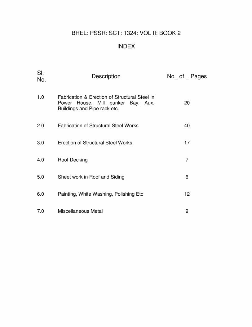
BHEL: PSSR: SCT: 1324: VOL II: BOOK 2
INDEX Sl. No.
Description No_ of _ Pages
1.0 Fabrication & Erection of Structural Steel in
Power House, Mill bunker Bay, Aux. Buildings and Pipe rack etc.
20
2.0 Fabrication of Structural Steel Works 40 3.0 Erection of Structural Steel Works 17 4.0 Roof Decking 7 5.0 Sheet work in Roof and Siding 6 6.0 Painting, White Washing, Polishing Etc 12 7.0 Miscellaneous Metal 9

TITLE: FABRICATION & ERECTION OF
STRUCTURAL STEEL IN POWER
HOUSE, MILL BUNKER BAY,
AUXILIARY BUILDINGS AND PIPE
RACK ETC
SPECIFICATION NO. PE-TS-307-600-C003
VOLUME II
SECTION
REV.NO. 0 DATE 12/09/2008
SHEET 1 OF 20
VOLUME: II
TECHNICAL SPECIFICATIONS
FOR
FABRICATION & ERECTION OF STRUCTURAL STEEL IN POWER
HOUSE, MILL BUNKER BAY, AUXILLIARY BUILDINGS AND PIPE
RACK ETC
SPECIFICATION NO. PE-TS-307-600-C003
BHARAT HEAVY ELECTRICALS LIMITED
POWER SECTOR
PROJECT ENGINEERING MANAGEMENT
NEW DELHI,INDIA
TITLE: FABRICATION & ERECTION OF
STRUCTURAL STEEL IN POWER
HOUSE, MILL BUNKER BAY,
AUXILIARY BUILDINGS AND PIPE
RACK ETC
SPECIFICATION NO. PE-TS-307-600-C003
VOLUME II
SECTION
REV.NO. 0 DATE 12/09/2008
SHEET 2 OF 20
PROJECT TITLE : NORTH CHENNAI TPS STAGE II
NO. OF UNITS : ONE
LOCATION : ATHIPATTU , TAMIL NADU

TITLE: FABRICATION & ERECTION OF
STRUCTURAL STEEL IN POWER
HOUSE, MILL BUNKER BAY,
AUXILIARY BUILDINGS AND PIPE
RACK ETC
SPECIFICATION NO. PE-TS-307-600-C003
VOLUME II
SECTION
REV.NO. 0 DATE 12/09/2008
SHEET 3 OF 20
PROJECT SYNOPSIS
OWNER TAMIL NADU ELECTRICITY BOARD
NAME OF PROJECT NORTH CHENNAI TPS STAGE II
SITE LOCATION
ATHIPATTU, POONERI TALUK, 35 KMS
NORTH OF CHENNAI .
NEAREST RAILWAY STATION ATHIPATTU PUDUNAGAR ON CHENNAI
HOWRAH MAIN LINE , 3 KM FROM SITE
NEAREST AIRPORT CHENNAI—35 KMS FROM SITE
INSTALLED CAPACITY STAGE II 2 X 6OO MW

TITLE: FABRICATION & ERECTION OF
STRUCTURAL STEEL IN POWER
HOUSE, MILL BUNKER BAY,
AUXILIARY BUILDINGS AND PIPE
RACK ETC
SPECIFICATION NO. PE-TS-307-600-C003
VOLUME II
SECTION
REV.NO. 0 DATE 12/09/2008
SHEET 4 OF 20
SECTION A
SCOPE OF WORK

TITLE: FABRICATION & ERECTION OF
STRUCTURAL STEEL IN POWER
HOUSE, MILL BUNKER BAY,
AUXILIARY BUILDINGS AND PIPE
RACK ETC
SPECIFICATION NO. PE-TS-307-600-C003
VOLUME II
SECTION
REV.NO. 0 DATE 12/09/2008
SHEET 5 OF 20
1.0 SCOPE OF WORK
The Scope of Work consists of the following:
This specification covers Transporting from BHEL Stores, Fabrication, testing,
painting and delivery to site & Erection, Alignment, Painting of structural
steelwork including supply of all consumable stores and rivets, bolts, nuts,
washers, electrodes and other materials required for Fabrication & Erection and
field connections of all structural steelwork covered under the scope of the
contract.
Preparation of fabrication drawings, joint design calculations and all other
general and special requirements including appointment of a separate agency,
approved by BHEL, for review and approval of fabrication drawings (prepared
by the bidder) in consultation with BHEL, and all other activities required for
completion of the work including return of surplus/ waste steel materials to
store etc. as per specification, drawings and instructions of the Engineer.
Approval of fabrication drawings does not relieve the bidder from the
responsibility of its correctness and accuracy.
2.0 The works to be performed under this contract consist of providing all labour,
supervision, material, scaffolding, construction equipments, tools and plants,
temporary works, supplies including POL, transportation and all incidental
items not shown or specified but reasonably implied or necessary for the proper
completion of work in all respects. Testing of all materials, concrete,
earthwork, other allied works, preparation of bar bending schedules on the basis
of construction drawings, preparation of fabrication drawings etc. are included
in the rates of items of work. Works shall only be carried out with approved
structural fabrication drawings.
3.0 Fabrication and Erection of Structural Steel work involving rolled section,
sections fabricated out of plates chequered plates/ M.S. gratings, hand rails,
primer and final painting for all Structural Steel works including supply of
HSFG Bolts if any, low hydrogen quality electrodes for welding, non
destructive testing etc., complete as per Quality Plan/Customer requirements.
4.0 The area of work shall be cleared of all vegetation, rubbish and other
objectionable matter, and materials removed, shall be burnt or otherwise
disposed of as directed by the Engineer-in-Charge.
5.0 All gold, silver, oil or other minerals of any description and all precious stones,
coils, treasures, relics, antiques, and other similar things which may be found in
or upon the site shall be the property of BHEL. The contractor shall duly
preserve the same and from time to time deliver the same to such person or
persons as BHEL may from time to time appoint to receive the same.

TITLE: FABRICATION & ERECTION OF
STRUCTURAL STEEL IN POWER
HOUSE, MILL BUNKER BAY,
AUXILIARY BUILDINGS AND PIPE
RACK ETC
SPECIFICATION NO. PE-TS-307-600-C003
VOLUME II
SECTION
REV.NO. 0 DATE 12/09/2008
SHEET 6 OF 20
6.0 All the works areas shall be adequately flood lighted to the satisfaction of the
Engineer-in-Charge when the work is in progress during the night shifts.
7.0 Layout and Levels
Before start of the work, one reference line and two bench marks will be
established by BHEL. Permanent base lines and cross lines shall be established
by the Contractor at sufficiently close intervals as may be directed by the
Engineer with bench marks at all end points to serve as `Reference Grid’.
The contractor shall provide at his expense all templates, pillars and stakes,
equipment, materials and labour for establishing the Grid lines and Pillars and
shall be responsible for their maintenance during the entire period of
construction. The contractor shall maintain a certified copy of drawing showing
such approved reference lines, marks and levels and shall not remove any of
them without the prior approval of the Engineer-in-Charge. The reference
points and pillars already established by BHEL in the works area shall be fully
protected and maintained by the contractor. He shall repair and rebuild the
same in case of any damage.
The contractor shall layout the work from these reference base lines in
consultation with the Engineer-in-Charge and shall be responsible for the
correctness of all measurements and any connection therein, notwithstanding
the fact that the same might have been checked by the staff of the Engineer-in-
Charge.
The contractor shall be responsible for the proper execution of the work to such
lines and grades as may be specified in the drawing or established or indicated
by the Engineer-in-Charge from time to time.
8.0 Setting of laboratory :
The contractor shall set up his own laboratory in the very close vicinity of the
work site as per the directions of Engineer-in-charge at his cost.
The laboratory shall be equipped with latest testing equipment in sufficient
numbers to carry out all the tests as required under the contract. The contractor
shall ensure that the equipment is available well in advance of starting of the
work to avoid stoppage of work on this account.
All the tests shall be carried out by the contractor in presence of Engineer’s
representative and a joint record of all observations and results thereof shall be
maintained, and available with the Engineer.
TITLE: FABRICATION & ERECTION OF
STRUCTURAL STEEL IN POWER
HOUSE, MILL BUNKER BAY,
AUXILIARY BUILDINGS AND PIPE
RACK ETC
SPECIFICATION NO. PE-TS-307-600-C003
VOLUME II
SECTION
REV.NO. 0 DATE 12/09/2008
SHEET 7 OF 20
No separate payment for these operations/tests and for setting of laboratory shall
be made. The cost of these operations shall be deemed to have been included in
the unit rates tendered for the different items under bill of quantities.
9.0 The unit rates shall include all tools, tackles, material, equipment, fixtures,
labour, temporary works and everything whether of permanent or temporary
nature necessary for the completion of the job in all respects..
10.0 Purchaser reserves the unilateral right to split the package in whatsoever manner
he thinks fit, to facilitate the ease of handling of the package. Decision shall be
final and binding on the bidder. The same shall need explicit concurrence of the
Bidder.
11.0 The Contractor must visit the site prior to submitting his quotations to acquaint
himself fully with the nature, type and scope of work and involvement therein.
The rates quoted shall remain firm during entire period of execution till
completion of the work and any additional claim for lack of knowledge shall not
be entertained.
TITLE: FABRICATION & ERECTION OF
STRUCTURAL STEEL IN POWER
HOUSE, MILL BUNKER BAY,
AUXILIARY BUILDINGS AND PIPE
RACK ETC
SPECIFICATION NO. PE-TS-307-600-C003
VOLUME II
SECTION
REV.NO. 0 DATE 12/09/2008
SHEET 8 OF 20
VOLUME-II B
SECTION C
SPECIFIC TECHNICAL REQUIREMENTS
SPECIFICATION NO. PE-TS-307-600-C003
TITLE: FABRICATION & ERECTION OF
STRUCTURAL STEEL IN POWER
HOUSE, MILL BUNKER BAY,
AUXILIARY BUILDINGS AND PIPE
RACK ETC
SPECIFICATION NO. PE-TS-307-600-C003
VOLUME II
SECTION
REV.NO. 0 DATE 12/09/2008
SHEET 9 OF 20
1.0 STRUCTURAL STEEL WORKS
1.01 Structural Steel shall conform to IS:2062 Grade – A for rolled steel members
or plates up to 20 mm thickness. For plates above 20 mm thickness and
welded construction steel conforming to IS:2062 Grade – B (killed and
normalized) shall be used except for crane girders where Grade – C (IS:2062)
steel shall be used. Steel shall be procured from SAIL or any other approved
main producer.
1.02 Chequered plate shall conform to IS:3502 (latest) and minimum thickness of
chequered plate for floorings, covers etc. shall be 6 mm O/P.
1.03 For hand railings GI pipe of medium grade conforming to IS:1239 and
galvanized shall be smooth, conforming to IS:2633 shall be used. Hand railing
shall be flush welded construction, ground smooth using 32 mm Nominal Bore
of 42.2 mm outside diameter pipe, provided with double rail and pipe posts.
Top rail shall be provided at 1000 mm above platform or as approved and pipe
posts spaced not more than 1500 mm center to center. Hand rails post and rails
shall have one coat of red oxide zinc chromate primer. Final painting shall be
same as given for painting on structures.
1.04 CONNECTIONS
Connections shall be in line with detailed Customer Specifications.
Flux and wire combination for submerged Arc welding of Structural steel shall
be as follows :
Filler wire shall be Automelt Gr-C wire of classification AWS-A-5.17-EH14
and flux shall be of agglomerated type (Automelt Gr.-IV) of classification
AWS-A-5.17-F7A2EH 14 of Advani-Oerlikon make.
Following connections shall be provided during erection :
1. Welded Connections :
i. Connection of secondary beam to Main Beam.
ii. Connection of Bracing to Column.
iii. Connection of Brackets from column.
iv. Splicing of column/Transverse Frame Beam
v. Connection of Frame Beam to column.
vi. Connection of Bracing to longitudinal Tie Beam.
TITLE: FABRICATION & ERECTION OF
STRUCTURAL STEEL IN POWER
HOUSE, MILL BUNKER BAY,
AUXILIARY BUILDINGS AND PIPE
RACK ETC
SPECIFICATION NO. PE-TS-307-600-C003
VOLUME II
SECTION
REV.NO. 0 DATE 12/09/2008
SHEET 10 OF 20
vii. Connection of Longitudinal Tie Beam to column.
viii. Connection of Spandrel Beam to Column.
ix. Connection of other secondary structures.
2. HSFG connection (Grade 8.8 bolts)
i. Connection of Crane Girder to column.
ii. Connection between Crane Girders.
iii. Connection of members where tension shall be in the fastener.
3. Bearing Type conection (H.T. bolts Grade 8.8)
i. All removable type connections.
4. M.S Bolts (Gr. 4.6)
i. Purlins, stairs.
5. Low Hydrogen Electrodes as approved by the Engineer shall invariably be
used in the following cases :
i. For welding of all important joints such as Butt joints in Columns (flange or
web), Butt joints in Main frame Beams (Flange or web) etc.
ii. For welding steel having thickness more than 20 mm.
In case of fillet weld between two components, the thickness of the thicker part shall
be considered as the limit for (ii)
Minimum preheat & inter pass temperatures for welding over 40mm to 63 mm
(thickness of the thicker part at the point of welding) shall be 66° C and for over 63
mm, it shall be 110° C. However, higher preheat & inter pass temperatures may be
required due to joint restraint etc and shall be followed as per approved welding
procedure.
M.S. Gratings in Pump House shall be hot dip galvanized in accordance with
IS – 4759. The fasteners shall also be galvanized in terms of IS- 5358. Galvanizing
of steel structure shall be done after all fabrication work is completed. However,
fasteners may be tapped or re-run after galvanizing. Threads of bolts and nuts shall be
capable of developing the full strength of the bolt. The spring washers shall be
electro-galvanized as per IS:1573. All galvanizing shall be uniform and of standard
quality and shall withstand test in accordance with IS:2633. Zinc coating over
galvanized surface of structural members and threaded fasteners shall not be less than
610 gm Per Sq. m. & 375 gm. Per Sq. m. of surface area respectively.
TITLE: FABRICATION & ERECTION OF
STRUCTURAL STEEL IN POWER
HOUSE, MILL BUNKER BAY,
AUXILIARY BUILDINGS AND PIPE
RACK ETC
SPECIFICATION NO. PE-TS-307-600-C003
VOLUME II
SECTION
REV.NO. 0 DATE 12/09/2008
SHEET 11 OF 20
Shop primer paint shall be single coat of Red Oxide Zinc – Chromate Primer and
shall conform to IS:2074 in all respects. The surface preparation shall be done in
accordance with IS:1477 (Part I & II) – Code of Practice for finishing of Ferrous
Metals in Buildings.
1.05 Design Of Connections
i/ Fabrication drawings shall be prepared according to the provision of IS:800,
IS:816, IS:9595, IS:1367 and IS:9178.
ii/ Connection of vertical bracings with connecting members and diagonals of truss
members shall be designed for full tensile capacity of the bracings.
iii/ Size of fillet weld for flange to web connection for built up section shall be as
follows :
a. Full shear capacity for box section.
b. 80% of full shear capacity or actual shear (if indicated in drawings) or 0.5
times of the web thickness which ever is more. For I section Weld shall be
double fillet.
c. All welds shall be continuous. The minimum size of the fillet weld shall be as
per relevant IS code .
iv/ Shear connections shall be designed for 60% of section strength or actual shear(if
indicated in drawings) for rolled sections and 80% of section strength or actual
shear (if indicated in drawings) for built up section or rolled section with cover
plates.
v/ Moment connections between beam and column shall be designed for 100% of
moment capacity of the beam section.
vi/ All butt welds shall be full penetration butt welds.
vii/ The connection between top flange & web of crane girder shall be full penetration
butt weld & for bottom flange, connection may be fillet weld.
viii/Connection of base plate & gusset members with the columns shall be done
considering that total load gets transferred through weld.
TITLE: FABRICATION & ERECTION OF
STRUCTURAL STEEL IN POWER
HOUSE, MILL BUNKER BAY,
AUXILIARY BUILDINGS AND PIPE
RACK ETC
SPECIFICATION NO. PE-TS-307-600-C003
VOLUME II
SECTION
REV.NO. 0 DATE 12/09/2008
SHEET 12 OF 20
ix/ Splicing : All splicing work shall be full strength. Field splicing shall be done
with web /flange cover plates. For, exceptional cases the field splicing shall be
designed for 50% of load carried by the cover plates and remaining 50% load
through full penetration butt weld. Shop splicing for all sections other than rolled
shall be carried out by full penetration butt welds with no cover plates. Splicing
for all rolled sections shall be carried out using web and flange cover plate.
1.06 Minimum Tests To be Carried Out During Fabrication & Erection Of Structural
Steel
1. Steel
Ultrasonic test: plates above 25mm thickness shall be subjected to ultrasonic test as
per ASTM-A435 or equivalent to check the presence of Lamination.
2. Fillet Weld
Dye penetration test : 5% of the total length, Dye penetration shall be carried out to
the root run.
3. Butt Weld
Dye penetration test: 10% of the total length, Dye penetration test shall be carried out
to the root run after back gouging.
Radiography: Generally, splicing shall not be provided in tension flange of Bunker
Girders. Spot radiography shall be carried out on 100% joints in Tension zone &10%
joints in compression zone. Minimum 300 mm length shall be spot radio-graphed.
When radiograph is not possible ultrasonic test shall be carried out after grinding the
surface with prior approval of Engineer.
Ultrasonic Test: 10% of all other Butt welds shall be subject to spot radiographic test
and the entire balance butt weld for ultrasonic test.
1.07 Painting of Structures
Material
Material shall be highest- grade products and shall be delivered to the site in original
sealed containers, bearing brand name, manufacturer’s name and colour shade with
labels intact and seals unbroken. All materials shall be subject to inspection,
analysis and approved by the Engineer. For satisfactory results, it is desired that
primer and finishing paints etc. are to be obtained by the bidder from the same
manufacturer. All paints shall be subject to analysis from random sample taken at
site from painters bucket, if so desired by the Engineer. Paint shall be stirred
frequently to keep the pigment in suspension. Paint shall be ready mixed in original
sealed container as packed by the paint manufacturer. Paints purchased for the work
TITLE: FABRICATION & ERECTION OF
STRUCTURAL STEEL IN POWER
HOUSE, MILL BUNKER BAY,
AUXILIARY BUILDINGS AND PIPE
RACK ETC
SPECIFICATION NO. PE-TS-307-600-C003
VOLUME II
SECTION
REV.NO. 0 DATE 12/09/2008
SHEET 13 OF 20
shall be brought to site in sealed container and shall be opened in the presence of the
Engineer or his authorized representative.
Paints, primers etc required under this contract should be procured from approved
manufacturers, viz. Berger Paints or any other equivalent sources approved by
BHEL. In this regard, BHEL's decision is final and binding to the bidder. Each and
every supply of primer, finishing paints, etc. should be accompanied by
manufacturer’s test certificates. At the time of procurement, the bidder should
furnish all the procurement details to BHEL i.e., the type of material procured
(primer, finishing paints etc.), quantity, source of procurement and shall submit all
test certificates to BHEL. Bidder shall supply the paints in the exact colour / shade
and type of finish of the paint, as per direction of BHEL and no extra payment shall
be entertained by BHEL for the above.
All colours shall be approved by Engineer and tinting and matching shall be done to
the satisfaction of the Engineer. In such case where samples are required they shall
be executed in advance with the specified materials for the approval of the Engineer.
Primer (Red Oxide Zinc Chromate)
The primer shall be Red Oxide Zinc Chromate conforming to the requirements of
IS:2074 (Latest) Ready Mixed Paint, Air Drying, Red Oxide Zinc Chromate primer.
The primer should conform to all the requirements of IS code and any deviation in
any respect from IS code shall not be accepted. The paint should be approved by the
Engineer.
Finishing Coats (Synthetic Enamel Paint)
The finishing coats shall be Synthetic Enamel paint conforming to IS:2932 (Latest)-
“Enamel Synthetic, Exterior: (A) Undercoating (B) Finishing – Specification”. The
paint shall give a smooth, hard, durable and glossy finish to all surfaces. Bidder
shall supply the paints in the exact colour / shade and type of finish of the paint, as
per direction of BHEL and no extra payment shall be entertained by BHEL for the
above. The paint should conform to all the requirements of IS code and any
deviation in any respect from IS code shall not be accepted. The paint should be
approved by the Engineer.
Surface Preparation And Pre-Treatment (Structure)
The surface preparation shall be done in accordance with IS:1477-Part-I (latest)-
“Code of Practice for painting of Ferrous Metals in Buildings: Part I (Pre-
Treatment)” and as directed by the Engineer.
The metal surfaces shall be absolutely clean, dry and free from rust, scales, weld
stag, flux deposit, soap films, wax, dirt, oil, grease, foreign matters like cement

TITLE: FABRICATION & ERECTION OF
STRUCTURAL STEEL IN POWER
HOUSE, MILL BUNKER BAY,
AUXILIARY BUILDINGS AND PIPE
RACK ETC
SPECIFICATION NO. PE-TS-307-600-C003
VOLUME II
SECTION
REV.NO. 0 DATE 12/09/2008
SHEET 14 OF 20
mortar, etc. and free from existing loose red oxide zinc chromate primer and should
be removed by means of wire brushes, hand-scrappers, sand paper, emery cloth,
emery papers, mechanical power tools, etc. or by other effective methods, such as
using solvent cleaning etc. where necessary and as per relevant IS codes and as
directed by the Engineer. It should be remembered that perfectly clean surface is of
great importance while dealing with die painting of ferrous metal. The surfaces
should be carefully inspected and in cases, where the existing red oxide primer is
removed while cleaning the surfaces, the damaged portion should be thoroughly
degreased by clean solvent swabbing, any corrosion products formed should be
thoroughly removed and touched up with a coat of red oxide zinc chromate primer.
No extra payment shall be entertained by BHEL for the above. The actual painting
work should be commenced only after obtaining clearance from the Engineer or his
authorized representative regarding proper cleaning of the surface.
1.08 Application (Structure)
General
The painting work shall be carried out as per the colour scheme of BHEL/Owner or
as per direction of the Engineer and the Bidder shall procure the paints accordingly.
The method of application shall be as recommended by the manufacturer. In case of
selection of special shades and colour (not available in standard shades) the Bidder
shall mix different shades and prepare test panels of minimum size 1 meter square as
per instruction of the Engineer and obtain his approval prior of application of
finishing paints.
Immediately after the preparation of the surface, and providing the touch of primer
in the damaged area, the first coat of primer shall be provided by brush and ensuring
a continuous film without ‘holidays'. After the first coat is hard dry, apply a second
coat of primer so that a film perfectly free from 'holidays' is obtained. The second or
subsequent finishing coats may be applied after the first finishing coat is hard dry
and its gloss is knocked off by scuffing with a very fine cutting device. The surface
should be dry, clean, and free from dust and moisture before subsequent coat is
applied. It is essential to avoid corrosion or any other paint defects, which may result
due to trapped or foreign materials in the paint film. All painting work shall be done
in accordance with relevant I. S codes.
Proper tools and implements shall be used. Scaffoldings, if used, shall be
independent of the surface to be painted to avoid shade differences of the freshly
repaired anchor holes. Painting shall be done by skilled labours in a workman like
manner. All materials shall be applied evenly and thoroughly so as to be free of
sags, runs, crawls or other defects. All coats shall be of proper consistency. In case
of application by brush, no brush marks shall be visible. The brushes shall be clean
and in good condition before application of paint. The use, conditioning and
maintenance of brushes for painting shall conform to the requirements given in

TITLE: FABRICATION & ERECTION OF
STRUCTURAL STEEL IN POWER
HOUSE, MILL BUNKER BAY,
AUXILIARY BUILDINGS AND PIPE
RACK ETC
SPECIFICATION NO. PE-TS-307-600-C003
VOLUME II
SECTION
REV.NO. 0 DATE 12/09/2008
SHEET 15 OF 20
Appendix-A of IS:1477-part-II (latest).
No work shall be done under conditions that are unsuitable for production of good
results. Application of paint which seals the surface to moisture shall only be done
after the moisture on and below the surface has dried out. All coats shall be
thoroughly dry before succeeding coat is applied. Coats of painting as specified are
intended to cover surfaces perfectly. In case the surface is not covered properly by
applying specified number of coats, further coats shall be applied by the Bidder to
conform the paint as per acceptance criteria of this contract. Approval of the
Engineer is to be obtained by the Bidder before application of each coat and no paint
shall be applied until the surface for painting has been accepted by the Engineer.
The sequence of painting of the structural members shall be as per direction of
BHEL and binding on the bidder. Finishing coats shall be of exact colour and shade
as per approved samples and all finish shall be uniform in colour and texture. All
parts of mouldings and ornaments shall be left clean and true to finish.
1.09 Structural Steel Painting
As preventive measure against the aggressive atmospheric environment, the
following measures (using chemical paint) shall be adopted by the bidder as
minimum requirement for all steel structures.
i) All steel members of buildings and structures shall be provided with suitable
protective coating. The minimum maintenance free life of protective coating shall
be ten years expected life ( long range 10 to 20 years as per BS 5493).
Considering exterior exposed to non-polluted inland atmosphere & interior
normally dry using minimum 75 micron DFT in organic zinc silicate primer
(applied over blast cleaned surface to near white metal ). However, for sheltered
structures where sides are not fully covered such as conveyor galleries, deareator
floor, bunker building, transfer tower etc., both inside and outside of structure
shall be considered as exposed to non polluted inland atmosphere. Intermediate
coat shall be of epoxy based T102 or M10 of minimum 75 micron DFT. Interior
structure shall be finished with ( minimum 75 micron DFT) chlorinated rubber
paint of approved shade. Exterior structure shall be finished with ( minimum 70
micron DFT) epoxy based paint. Exterior structure shall further be finished with
top coat of ( minimum 30 micron DFT) polyurethane of approved shade. All paint
shall be of high built constitution.
i) All mild steel parts coming in contact with water or water vapour shall
be hot dipped galvanised. The minimum coating of zinc shall be 610
gm./sq. m. for galvanised structures and comply with IS: 4759 and
other relevant codes. Galvanizing shall be checked out tested in
accordance with IS:2629.

TITLE: FABRICATION & ERECTION OF
STRUCTURAL STEEL IN POWER
HOUSE, MILL BUNKER BAY,
AUXILIARY BUILDINGS AND PIPE
RACK ETC
SPECIFICATION NO. PE-TS-307-600-C003
VOLUME II
SECTION
REV.NO. 0 DATE 12/09/2008
SHEET 16 OF 20
The galvanising shall be followed by the application of an etching
primer and dipping in black bitumen in accordance with BS:3416,
unless otherwise specified.
Minimum Total Thickness Of Paint
Painting on ferrous metal surface shall be done as per IS:1477(part I &II). The total
dry film thickness of the finished paint should not be less than 100 microns,
including (whatever may be available ) dry film thickness of the existing red oxide
zinc chromate primer. The thickness shall be measured by elchometer or any other
approved method as directed by the Engineer.
2.00 Painting On Masonry & Concrete Surfaces
2.01 All painting on masonry or concrete surface shall preferably be applied by roller. It
applied by brush then same shall be finished off with roller.All paints shall be of
approved make including chemical resistant chlorinated rubber paint.Minimum two
finishing coats of paint shall be applied over a coat of primer.The thinner shall not be
used with textured paint (Sandtex Matt or equivalent) finish.
2.02 Acrylic emulsion paint shall be as per IS: 5411 (part 1). Oil bound distemper shall be
as per IS : 428. Cement paint shall confirm to IS-5410, white wash / colour wash shall
confirm to IS-627, plaster of paris punning (minimum 2 mm) shall be provided.
2.03 Fire resistant transparent paint (conforming to IS : 162) shall be provided on all wood
work over French polish or flat oil paint. French polish shall conform to IS : 348.
Flat oil paint shall conform to IS : 137.
2.04 All fire exits shall be painted in post office red/signal red colour shade, which shall not
be used anywhere else except to indicate emergency or safety measure.
2.05 For painting on concrete, masonry and plastered surface IS : 2395 shall be followed.
For painting on steel work and ferrous metals, IS : 1477 shall be followed. For
painting on wood work IS : 2338 shall be followed.
2.06 Bitumen primer used in acid/alkali resistant treatment shall conform to IS : 158.
2.07 Exterior masonry paint (water or solvent based ) shall consist of special resins and
additives , mixed with fine, hard stone aggregates & finest available pigments. The
paint shall be applied on a coat of primer over dried, prepared plastered surface as per
manufacturer's guidelines. The final, finished coating shall be fungus resistant, UV
resistant, water repellent, alkali resistant, and extremely durable with colour fastness.

TITLE: FABRICATION & ERECTION OF
STRUCTURAL STEEL IN POWER
HOUSE, MILL BUNKER BAY,
AUXILIARY BUILDINGS AND PIPE
RACK ETC
SPECIFICATION NO. PE-TS-307-600-C003
VOLUME II
SECTION
REV.NO. 0 DATE 12/09/2008
SHEET 17 OF 20
2.08 All plastered areas above false ceiling shall be provided with two or more coats of
white wash.
2.09 Resin bonded granular textured finish, for external applications shall consist of crushed
stone/quartz chips of 0.5 mm to 2.5 mm size and of approved natural colour/ shade
and bonded with synthetic resins, Adhesives and additives, all together in a single
pack mix. It shall be applied externally, on cured and dried plastered surfaces, with a
dry film thickness of min. 2.0 mm. The final finish shall have UV-Resistant, fungus
/bacterial resistant properties. Grooves shall be provided as per drawing and the same
shall be filled with polysulphide sealant of matching shade/shade.
3.00 Materials
3.07 Grouting materials : shall be Conbextra GP –2 of `Fosroc’ make or equivalent for
Power House & equipment foundations and Conbextra GP – 1 for other foundations.
3.08 Acid Alkali resistant tiles : shall be of approved thickness and shall conform to IS
4457 & IS : 4832 (Pt-1).
3.09 C.G.I. Sheet : thickness of C.G.I sheet shall not be less than 22 g and minimum grade
of galvanization shall be 450gms/m2.
3.10 Glazing : For glazing, Float Glass (Modi Guard or equivalent) shall be used.
6.00 STATUTORY REQUIREMENTS
6.01 Bidder shall comply with all the applicable statutory rules pertaining to Factories Act.
Fire Safety Rules of Tariff Advisory Committee, Water Act for Pollution Control,
Explosives Act, etc.
6.02 Provisions of safety, health and welfare according to Factories Act shall be complied
with. These shall include provision of continuous walkway minimum 500 wide along
the crane-girder level on both sides of building, comfortable approach to EOT crane
cabin, railing, fire escape, locker room for workmen, pantry, toilets, rest room, etc.
6.03 Provisions for fire proof doors number of staircases, fire separation wall, lath
plastering/encasing the structural members (in the fire prone areas), type of glazing
etc. shall be made according to the recommendations of Tariff Advisory Committee.
6.04 Statutory clearances and norms of State Pollution Control Board shall be followed.
6.05 Bidder shall obtain approval of Civil/Architectural drawings from concerned
authorities before taking up the construction work.
TITLE: FABRICATION & ERECTION OF
STRUCTURAL STEEL IN POWER
HOUSE, MILL BUNKER BAY,
AUXILIARY BUILDINGS AND PIPE
RACK ETC
SPECIFICATION NO. PE-TS-307-600-C003
VOLUME II
SECTION
REV.NO. 0 DATE 12/09/2008
SHEET 18 OF 20
7.00 LAYOUT
7.01 Before starting the work, the Contractor shall carry out the setting out of foundation
and structures and provide levels, with reference to general existing grid and bench
mark. If the contractor uses the grid, , bench mark and reference pillar made by
other Contractors, he shall coordinate with the Contractor and shall satisfy himself
of the accuracy of the reference marks. If he is required to set out the foundation
afresh, he shall do so independently with reference to the one existing grid and bench
mark which has been followed by other agency at the instruction of the Engineer. In
case any discrepancy be found. It shall be immediately brought to the notice of the
engineer for any rectification/modification necessary. No complaint shall be
entertained at a later stage. The Contractor shall accurately set out the position for
holding down bolts and inserts.
7.02 If required, in the opinion of the Engineer, he shall construct and maintain pillars for
Grid, references and bench marks and maintain them till the completion of the
construction. He shall also help the Engineer with instruments, materials and labours
for checking the detailed lay outs and levels. The Contractor shall be solely
responsible for the correctness of the layout and levels, and Engineer’s approval
shall not be deemed to imply any warranty in carrying out the work correctly.
8.00 WORKMANSHIP
8.01 Workmanship shall be of the best possible quality and all work shall be carried out by
skilled workmen except for those which normally requires unskilled persons.
Welding shall be done by experienced and certified welders in proper sequence using
necessary jigs and fixtures. Fabrications shall be done in shops having proper
equipment for accurate edge planing and milling of column shell ends, base plate
surfaces etc. and shaping and dimensioning of anchor bolt assembly, inserts and other
misc. items. In addition to the requirement specified above, if the bye-laws of the
local Govt., Municipal or other authorities require the employment of licensed or
registered workmen for various trades, the contractor shall arrange to have the work
done by such registered or licensed personnel. In case of manufactured materials, the
Contractor shall, with no additional cost to the owner, arrange the services of the
supervisors of the manufacturers to ensure that the work is being done according to
the manufacturer’s specifications.
9.00 TEMPORARY WORK
9.01 All scaffoldings, staging, temporary bracing and other necessary temporary work
required for proper execution of the Contract shall be provided by the Contractor at
his own cost and inclusive of all materials, labour, supervision and other facilities.
TITLE: FABRICATION & ERECTION OF
STRUCTURAL STEEL IN POWER
HOUSE, MILL BUNKER BAY,
AUXILIARY BUILDINGS AND PIPE
RACK ETC
SPECIFICATION NO. PE-TS-307-600-C003
VOLUME II
SECTION
REV.NO. 0 DATE 12/09/2008
SHEET 19 OF 20
9.02 The layout and details of such Temporary work shall have the prior approval of the
Engineer as agreed, but the Contractor shall be responsible for proper strength and
safety of the same. All Temporary work shall be constructed so as not to interfere
with any permanent work or with the work by other agencies. If it is necessary to
remove any of the temporary work at any time to facilitate execution of the work or
the work of other agencies, such removal and re-erection, if required, shall be carried
out by the Contactor at the discretion of the Engineer without any delay and any extra
cost on this account shall be borne by the Contractor.
10.00 INTERFACE WITH STRUCTURES UNDER OTHER’S SCOPE
10.01 In cases of interface e.g. structures under other’s scope of supply being supported on
structures under scope of this contractor, the same will be discussed and suitably
addressed.
10.02 Modification in layout of foundation/structure during detail engineering stage may be
necessary to avoid fouling with those under other’s scope. Necessary changes on this
account will be made without any extra cost to Owner.
a) Necessary engineering is to be done and provisions are to be kept accordingly by the
Contractor to construct foundations/underground structures, etc. without
disturbing/endangering the constructions done under the scope of other contracts.
11.00 INSPECTION, TESTING AND QUALITY CONTROL FOR CIVIL WORKS
11.01 Sampling and testing for major items of civil works viz earthwork, concreting,
structural steel work (including welding), etc. shall be carried out in accordance with
the requirements of this specification. Wherever nothing is specified relevant Indian
Standards may be used, in absence of Indian Standards, equivalent International
standards may be used.
11.02 The bidder shall submit for BHEL’s approval a detailed field quality assurance
programme for Civil Works before starting of the construction work. This shall
include frequency of sampling and testing nature/type of test, method of test, setting
of a testing laboratory, arrangement of testing apparatus/equipment, deployment of
qualified/experienced manpower, preparation of format for record, Field Quality Plan,
etc. Tests shall be done in the field and/or at a laboratory approved by the Engineer
and the Bidder shall submit to the Engineer, the test results in triplicate. In addition,
the bidder shall furnish the original test certificate from the manufacturers of various
materials to be used in the construction.
11.03 If any work is found to be of inferior quality or sub-standard, the same shall be
dismantled and shall be redone as per approved quality or relevant standard. BHEL
reserves the right to reject work of inferior quality. All expenses on account of
dismantling and rework shall be born by contractor.

TITLE: FABRICATION & ERECTION OF
STRUCTURAL STEEL IN POWER
HOUSE, MILL BUNKER BAY,
AUXILIARY BUILDINGS AND PIPE
RACK ETC
SPECIFICATION NO. PE-TS-307-600-C003
VOLUME II
SECTION
REV.NO. 0 DATE 12/09/2008
SHEET 20 OF 20
15.0 PTFE (Poly tetra fluorethylene) slide bearing
15.01 General
The bearing shall consist of upper and lower units. The upper unit shall include a
sole plate with mirror finish stainless steel facing bonded to the bottom surface of the
sole plate. The lower unit shall consist of a relevant laminated elastomers pad
surfaced with PTFE. A rigid confining medium substructure bonds the PTFE to the
pad. When the upper and lower units are mated the stainless steel slides on the PTFE
surface with an extremely low coefficient of friction. These bearings shall be
designed as per the performance requirements.
15.02 Material
The resilient bearing pad shall consist of multiple layers of light weight fabric
impregnated with a high quality elastomer compound vulcanised into slabs of
uniform standard thickness as per the requirement. This shall withstand compressive
load not less than 50 Kg/sqcm and shear loads up to 40 Kg/sqcm and shear stress up
to 50% without failure.
15.03 Installation
The seating area for PTFE bearing shall be prepared accurately level and furnished
with a thin layer of epoxy resin mortar. The bearing will be placed on this layer
while it is still workable and the bearing is levelled. The bearing should not be
displaced as the beam is lowered into position. When the mortar and adhesive are
fully set and the beams are ready for lowering temporary supports are set up ready
to support the beam slightly above the top of the bearing. The upper surface of the
bearing shall be coated with sufficient thickness of epoxy resin mortar so that when
the beam is lowered on to the temporary supports it comes into full contact with the
mortar and some is squeezed out. The surplus shall be troweled off and after the
mortar is fully set the temporary supports removed.
TITLE:
TECHNICAL SPECIFICATION FOR
FABRICATION OF STRUCTURAL
STEEL WORK
SPECIFICATION NO.
VOLUME - II B
SECTION - D (PART – I)
REV.NO. 0 DATE
SHEET 1 OF 40
VOLUME: II B
SECTION - D (PART I)
SUB-SECTION – D XVII
FABRICATION OF STRUCTURAL STEEL WORK
Bharat Heavy Electricals Limited Project Engineering Management

TITLE:
TECHNICAL SPECIFICATION FOR
FABRICATION OF STRUCTURAL
STEEL WORK
SPECIFICATION NO.
VOLUME - II B
SECTION - D (PART – I)
REV.NO. 0 DATE
SHEET 2 OF 40
C 0 N T E N T
CLAUSE NO. DESCRIPTION SHEET NO.
1.00.00 SCOPE 3
2.00.00 GENERAL 3
3.00.00 WORKMANSHIP 19
4.00.00 INSPECTION, TESTING, ACCEPTANCE
CRITERIA AND DELIVERY 29
5.00.00 INFORMATION TO BE SUBMITTED 33
6.00.00 RATES AND MEASUREMENTS 34
TITLE:
TECHNICAL SPECIFICATION FOR
FABRICATION OF STRUCTURAL
STEEL WORK
SPECIFICATION NO.
VOLUME - II B
SECTION - D (PART – I)
REV.NO. 0 DATE
SHEET 3 OF 40
SUB-SECTION – D XVII
FABRICATION OF STRUCTURAL STEEL WORK
1.00.00 SCOPE
This specification covers supply, fabrication, testing, painting and delivery to
site of structural steelwork including supply of all consumable stores and
rivets, bolts, nuts, washers, electrodes and other materials required for
fabrication and field connections of all structural steelwork covered under the
scope of the contract.
2.00.00 GENERAL
2.01.00 Work to be provided for by the Contractor
The work to be provided for by the Contractor, unless otherwise specified
elsewhere in the contract, shall include, but not be limited to the following
a) Preparation of complete detailed fabrication drawings and erection
marking drawings required for all the structures covered under the scope of
the contract based on the approved design drawings. As decided by the
Engineer, some or all of these detailed drawings will have to be submitted
for approval.
b) To submit revised design with calculations and detailed fabrication
drawings in case any substitution of the designed sections are to be made.
c) To submit design calculations for joints and. connections developed by the
contractor along with detailed fabrication drawings.
d) Furnish all materials, labour, tools and plant and all consumables required
for fabrication and supply, all necessary rivets, bolts, nuts, washers, tie
rods and welding electrodes for field connections,
e) Furnish shop painting of all fabricated steelwork as per requirements of
this Specification.
f) Suitably mark, bundle, and pack for transport all fabricated materials.
g) Prepare and furnish detailed Bill of Materials, Drawing Office Dispatch
lists, Rivet and Bolt List and any other list of bought out items required in
connection with the fabrication and erection of the structural steelwork.
h) Insure, load and transport all fabricated steelwork field connection
materials to site.

TITLE:
TECHNICAL SPECIFICATION FOR
FABRICATION OF STRUCTURAL
STEEL WORK
SPECIFICATION NO.
VOLUME - II B
SECTION - D (PART – I)
REV.NO. 0 DATE
SHEET 4 OF 40
i) Maintain a fully equipped workshop at site for fabrication, modification
and repairs of steelwork at site as may be required to complete the works
in accordance with the Contract.
2.02.00 Work by others
No work under this specification will be provided for by any agency other than
the contractor, unless specifically mentioned otherwise elsewhere in the
contract.
2.03.00 Codes and standards
All work under this specification shall, unless otherwise specified in the
contract, conform to the requirements of the latest revision and/or
replacements of the following or any other relevant Indian Standard
specifications and codes of practice. In case any particular aspect of the work
is not specifically covered by any Indian Standard specification, any other
standard practice, as may be specified by the Engineer shall be followed:
IS : 226 - Structural steel (Standard Quality)
IS : 800 - Code of Practice for general construction in steel.
IS : 806 - Code of practice for use of steel tubes in general building
construction.
IS : 808 - Rolled steel beams, channels, and angle sections
IS : 813 - Scheme of symbols for welding
IS : 814 - Covered electrodes for metal arc welding of structural steel
IS : 815 - Classification and coding of covered electrodes for metal arc
welding of structural steels.
IS : 816 - Code of practice for use of metal arc welding for general
construction in mild steel
IS : 817 - Code of practice for training and testing metal arc welders
IS : 818 - Code of practice for safety and health requirements in electric
and gas welding and cutting operations
IS : 822 - Code of practice for inspection of welds
IS : 919 - Recommendations for limits and fits for Engineering

TITLE:
TECHNICAL SPECIFICATION FOR
FABRICATION OF STRUCTURAL
STEEL WORK
SPECIFICATION NO.
VOLUME - II B
SECTION - D (PART – I)
REV.NO. 0 DATE
SHEET 5 OF 40
IS : 961 - Structural Steel (High Tensile)
IS : 1148 - Rivet bars for structural purposes
IS : 1149 - High tensile rivet bars for structural purposes
IS : 1161 - Steel Tubes for structural purposes
IS : 1200 - Method of measurement of steelwork and ironwork (Part 8)
IS : 1239 - Mild Steel Tubes
IS : 1363 - Black hexagon bolts, nuts and lock nuts (dia. 6 to 30 mm) and
black hexagon screws (dia 6 to 24 mm)
IS : 1364 - Precision and semi-precision hexagon bolts, screws, nuts and l
locknuts (dia, range 6 to 39 mm)
IS : 1367 - Technical supply conditions for threaded fasteners
IS : 1442 - Covered electrodes for the metal are welding of high tensile
structural steel
IS : 1608 - Method for tensile testing of steel products other than sheet
strip, wire and tube
IS : 1730 - Dimensions for steel plate, sheet, and strip for structural and
general engineering purposes.
IS : 1731 - Dimensions for steel flats for structural and general engineering
purposes
IS : 1852 - Rolling and cutting tolerances for hot-rolled steel products
IS : 1977 - Structural steel (ordinary quality) St-42-0
IS : 2062 - Steel for General Structural Purposes
IS : 2074 - Ready mixed paint, red oxide Zinc chromate priming
IS : 2595 - Code of Practice for Radiographic Testing
IS : 2629 - Recommended practice for Hot-Dip Galvanizing of Iron and
Steel
IS : 2633 - Method for testing uniformity of coating on Zinc Coated Articles

TITLE:
TECHNICAL SPECIFICATION FOR
FABRICATION OF STRUCTURAL
STEEL WORK
SPECIFICATION NO.
VOLUME - II B
SECTION - D (PART – I)
REV.NO. 0 DATE
SHEET 6 OF 40
IS : 3757 - High strength structural bolts
IS : 4759 - Specifications for Hot-Dip Zinc Coatings on Structural Steel
and other allied products
IS : 7205 - Safety Code for Erection of Structural Steelwork
IS : 7215 - Tolerances for fabrication of steel structures
IS : 7280 - Bare wire electrodes for submerged arc welding of structural
steels.
IS : 9595 - Recommendations for metal arc welding of carbon and carbon
manganese steels.
2.04.00 Conformity with Designs
The contractor shall design all connections, supply and fabricate all steelwork
and furnish all connection materials in accordance with the approved drawings
and/or as instructed by the Engineer keeping in view the maximum Utilization
of the available sizes and sections of steel materials. The methods of painting,
marking, packing and delivery of all fabricated materials shall be in
accordance with the provisions of the contract and/or as approved by the
Engineer. Provision of all relevant Indian Standard Specifications and Codes
of Practice shall be followed unless otherwise specified in the contract.
2.05.00 Materials to be used
2.05.01 General
All steel materials required for the work will be supplied by the contractor
unless otherwise specified elsewhere in the contract. The materials shall be
free from all imperfections, mill scales, slag intrusions, laminations, fittings,
rusts etc. that may impair their strength, durability, and appearance. All
materials shall be of tested quality only unless otherwise permitted by the
Engineer and/or Consultant. If desired by the Engineer, Test Certificates in
respect of each consignment shall be submitted in triplicate. Whenever the
materials are required to be used from unidentified stocks, if permitted by the
Engineer, a random sample shall be tested at an approved laboratory from each
lot of 50 tones or less of any particular section.
The arc welding electrodes shall be of approved reputed manufacture and
conforming to the relevant Indian Standard Codes of Practice and
Specifications and shall be of heavily coated type and the thickness of the
coating shall be uniform and concentric. With each container of electrodes,
the manufacturer shall furnish instructions giving recommended voltage and

TITLE:
TECHNICAL SPECIFICATION FOR
FABRICATION OF STRUCTURAL
STEEL WORK
SPECIFICATION NO.
VOLUME - II B
SECTION - D (PART – I)
REV.NO. 0 DATE
SHEET 7 OF 40
amperage (Polarity in case of D.C. supply) for which the electrodes are
suitable.
2.05.02 Steel
All steel materials to be used in construction within the purview of this
specification shall comply with any of the following Indian Standard
Specifications as may be applicable:
a) IS : 2062 - Steel for general structural purposes
b) IS : 961 - Structural steel High Tensile
c) IS : 1977 - Structural steel (Ordinary quality) St-42-0
In case of imported steel materials being used, these shall conform to
specifications equivalent to any of the above as may be applicable.
2.05.03 Rivet Steel
All rivet steel used in construction within the purview of this Specification
shall comply with one of the following Indian Standard Specifications as may
be applicable:
a) IS : 1148 - Rivet Bars for structural purpose
b) IS : 1149 - High tensile rivet bars for structural purposes. Where high
tensile steel is specified for rivets, steps shall be taken to ensure
that the rivets are so manufactured that they can be driven and
heads formed satisfactorily without the physical properties of
steel being impaired.
2.05.04 Electrodes
All electrodes to be used under the Contract shall be of approved reputed
manufacture and shall comply with any of the following Indian Standard
Specifications as may be applicable
a) IS : 814 - Covered electrodes for metal arc welding of structural
steel
b) IS : 815 - Classification and coding of covered electrodes for
metal arc welding of mild steel and low alloy high
tensile steel
c) IS : 1442 - Covered electrodes for the metal arc welding of high

TITLE:
TECHNICAL SPECIFICATION FOR
FABRICATION OF STRUCTURAL
STEEL WORK
SPECIFICATION NO.
VOLUME - II B
SECTION - D (PART – I)
REV.NO. 0 DATE
SHEET 8 OF 40
tensile structural steel
d) IS : 7280 - Bare wire electrodes for submerged arc welding of
structural steels
2.05.05 Bolts and Nuts
All bolts and nuts shall conform to the requirements of Indian Standard
Specification IS: 1367 - Technical Supply Conditions for Threaded Fasteners.
Materials for Bolts and nuts under the purview of this contract shall comply
with any of the following Indian Standard Specifications as may be applicable.
a) Mild Steel
All mild steel for bolts and nuts when tested in accordance with the
following Indian Standard Specification shall have a tensile strength of not
less than 44 Kg/mm² and a minimum elongation of 23 per cent on a gauge
length of 5.6 _/A, where "A" is the cross sectional area of the test
specimen
i) IS: 1367: Technical supply conditions for threaded fasteners
ii) IS: 1608: Method for tensile testing of steel products other than
sheet, strip, wire and tube
b) High Tensile Steel
The material used for the manufacture of high tensile steel bolts and nuts
shall have the mechanical properties appropriate to the particular class of
steel as set out in IS: 1367 or as approved by the Engineer.
2.05.06 Washers
Washers shall be made of steel conforming to any of the following Indian
Standard Specifications as may be applicable under the provisions of the
Contract:
a) IS : 2062 - Steel for general structural purposes
b) IS : 961 - Structural Steel ( High Tensile Quality)
c) IS : 1977 - Structural steel ( Ordinary Quality ) St-42-0
d) IS : 6649 - Hardened washers

TITLE:
TECHNICAL SPECIFICATION FOR
FABRICATION OF STRUCTURAL
STEEL WORK
SPECIFICATION NO.
VOLUME - II B
SECTION - D (PART – I)
REV.NO. 0 DATE
SHEET 9 OF 40
2.05.07 Paints
Paints to be used for shop coat of fabricated steel under the purview of this
contract shall conform to the Indian Standard Specification IS: 2074 - Ready
mixed Paint, Red oxide Zinc Chromate Priming.
2.06.00 Coal Bin
2.06.01 Shape of bins shall be circular, polygonal, square, or rectangular in plan.
Bottom hopper portion may have be conical-cum-hyperbolic or any other
profile shape as shown in the drawing. Bin shall be termed as bunkers or silos
according to their shape and plane of rupture of coal.
2.06.02 For general requirements, fabrication and construction details IS: 9178 (Pt.l &
11) shall be followed as general guidance. The bins shall be fabricated and
erected in segments.
2.06.03 The Coal bins shall be made of mild steel plates joined together with full
strength butt weld and provided with stiffeners at regular interval. Stiffeners
shall be provided on the external face and it may be welded with external face.
2.06.04 Bending of plates and rolled sections to the required shape for fabrication shall
be done by plate bending machine or cold bending process Without resorting
to heating, hammering, angle smithy and black smithy process.
2.06.05 Poking hole (manual or pneumatic) and striking plate shall be provided to
facilitate coal flow. Poking holes shall have circular MS pipe and cover cap as
detailed in the drawing.
2.07.00 New Erection Marks
2.07.01 Additional structures involving new erection marks may be required to be
added at any stage of work.
2.07.02 All such new erection marks shall be detailed and included in marking
schemes and fabrication carded out thereafter.
2.07.03 All such new erection marks shall be considered under item of original
fabrication work. As a result of additional structures becoming necessary if
the work is delayed beyond the time schedule stipulated, the Engineer shall
give suitable extension of time provided he is satisfied about the
reasonableness of the delay involved. However, no claim for extra payments
or revision of rates due to delay shall be entertained.

TITLE:
TECHNICAL SPECIFICATION FOR
FABRICATION OF STRUCTURAL
STEEL WORK
SPECIFICATION NO.
VOLUME - II B
SECTION - D (PART – I)
REV.NO. 0 DATE
SHEET 10 OF 40
2.08.00 ELECTRO FORGED STEEL GRATINGS
2.08.01 Factory made fabricated electro forged gratings unit with steel conforming to
IS: 2062 shall be supplied, fabricated, transported, erected and aligned in
floorings, platforms, drain and trench covers, walkways, passages, staircases
with edge binding strips and anti skid nosing in treads etc.
2.08.02 All grating units shall be rectangular in pattern and electro forged. The size
and the spacing of the bearing bars and cross bars shall be as detailed in
fabrication drawings. The contractor shall submit the grating design for
different spans and load intensities along with fabrication drawings. The depth
of the grating unit shall be 40 mm, unless specified otherwise.
2.08.03 The gratings shall be made up in panel units designed to coincide with the
span of the structural steel framing or openings as indicated in the design/
scope drawings. Maximum possible standardization of the grating panel sizes
shall be tried and designed.
2.08.04 The grating unit shall be accurately fabricated and finished, free from wraps,
twists, or any defects that would impair their strength, serviceability, and
appearance.
2.08.05 Grating work shall include cut outs and clearance opening for all columns,
pipes, ducts, conduits or any other installation penetrating through the grating
work. Such cut outs and clearances shall be treated as specified in subsequent
clauses.
2.08.06 The gratings shall be notched, trimmed and neatly finished around flanges and
webs of the columns, moment connections, cap plates, and such other
components of the steel structures encountered during the placement of the
gratings. In all such cases, the trimming shall be done to follow the profile of
the components encountered. After trimming, the binding strip shall be
provided on the grating to suit the profile so obtained.
2.08.07 Opening in gratings for pipes or ducts that are 150mm in size or diameter or
larger shall be provided with steel bar toe plates of not less than 5mm
thickness and appropriate width, set flush with the bottom of the bearing bars.
2.08.08 Penetrations in gratings that are more than 50mm but less than 150mm in size
or diameter shall be welded with plates of size shown in the detailed drawings
set flush with the bottom of the grating panel.
2.08.09 Unless otherwise indicated on the drawings, grating units at all penetrations
shall be made up in split section, accurately fitted and neatly finished to
provide for proper assembly and erection at the job site.

TITLE:
TECHNICAL SPECIFICATION FOR
FABRICATION OF STRUCTURAL
STEEL WORK
SPECIFICATION NO.
VOLUME - II B
SECTION - D (PART – I)
REV.NO. 0 DATE
SHEET 11 OF 40
2.08.10 Grating units shall be provided with all necessary clips, bolts, nuts and lock
washers required for proper assembly and rigid installation and fastening to
abutting units supporting structural steel framing members.
2.08.11 The gratings shall be of reputed make and manufacturer, as approved by
Engineer. The unit rate quoted by him for this item shall be inclusive of
transport of gratings to the project site, all taxes, duties etc. He shall also
provide all facilities and access to the Engineer or his representative to carry
out inspection during all stages of manufacturing of gratings.
2.08.12 Maximum deviation in linear dimension from the approved dimension shall
not exceed 12mm.
2.08.13 All fabricated grating section and accessories shall be blast cleaned to near
white metal surface (Sa 2½) followed by either of the following two:
(a) Two coats of red lead primer and two coats of black enamel finish paint.
(b) Hot dipped galvanization at 610 gm/sq.m.
in the shop prior to erection at site, as the approved drawing.
2.08.14 Prior to finishing all surfaces shall be cleaned, free from rust, mill scale,
grease, oil, or any other foreign matter by blast cleaning. BS: 4232 shall be
followed for blast cleaning.
2.08.15 Primer can be applied by spray guns or by brushes, however the finish paint
shall necessarily be applied by means of spray guns. The applied coatings
shall be uniform, free from voids and streaks; drilled or punched holes shall be
touched up prior to erection or assembly.
2.09.00 GALVANIZATION OF GRATINGS
2.09.01 Purity of Zinc to be used-for galvanizing shall be 99.5% as per IS: 2 15
2.09.02 After the shop work is complete, the structural material shall be punched with
erection mark and be hot double dip galvanized. Before galvanizing the steel
section shall be thoroughly blast cleaned to near white metal surface (Sa 2½).
2.09.03 The weight of the zinc coating shall be at least 610 gm/m² - unless noted
otherwise.
2.09.04 The galvanized surface shall consist of a continuous and uniformly thick
coating of zinc, firmly adhering to the surface of steel. The finished surface
shall be cleaned and smooth and shall be free from defects like discoloured
patches, bare spots, unevenness of coating, spelter that is loosely attached to

TITLE:
TECHNICAL SPECIFICATION FOR
FABRICATION OF STRUCTURAL
STEEL WORK
SPECIFICATION NO.
VOLUME - II B
SECTION - D (PART – I)
REV.NO. 0 DATE
SHEET 12 OF 40
the steel, blistered surface, flaking or peeling off etc. The presence of any of
these defects noticed on visual or microscopic inspection shall render the
material liable to rejection.
2.09.05 There shall be no flaking or loosening when struck squarely with a chisel faced
hammer. The galvanized steel member shall withstand minimum four one
minute dips in copper sulphate solution as per IS: 2633.
2.09.06 When the steel section is removed from the galvanizing kettle, excess spelter
shall be removed by 'bumping'. The processes known as 'wiping' or 'scrapping'
shall not be used for this purpose.
2.09.07 Defects in certain members indicating presence of impurities in the
galvanizing bath in quantities larger than that permitted by the specifications
or lack of quality control in any manner in the galvanizing plant, shall render
the entire, production in the relevant shift liable to rejection.
2.09.08 All structural steel shall be treated with sodium dichromate or an approved
equivalent solution after galvanizing; so as to prevent white storage stains.
2.09.09 If the galvanizing of any member is damaged, the Engineer shall be shown of
the extent of damage, if so directed the galvanizing may have to the redone in
the similar manner as stated above at no extra cost to the Owner.
2.10.00 STAINLESS STEEL HOPPERS
2.10.01 Material
Stainless steel hopper of grade SS 4 15M as manufactured by SAIL or
equivalent shall be provided in the lower portion of bunker hopper. SS 4 15M
having the following chemical composition shall be used.
Material % Remarks
Carbon 10.03% Max.
Silicon 1.60% Max.
Manganese 0.80% to 1.50%
Phosphorous 0.03% Max.
Sulpher 0.03% Max.
Chromium 10.80% to 12.50%
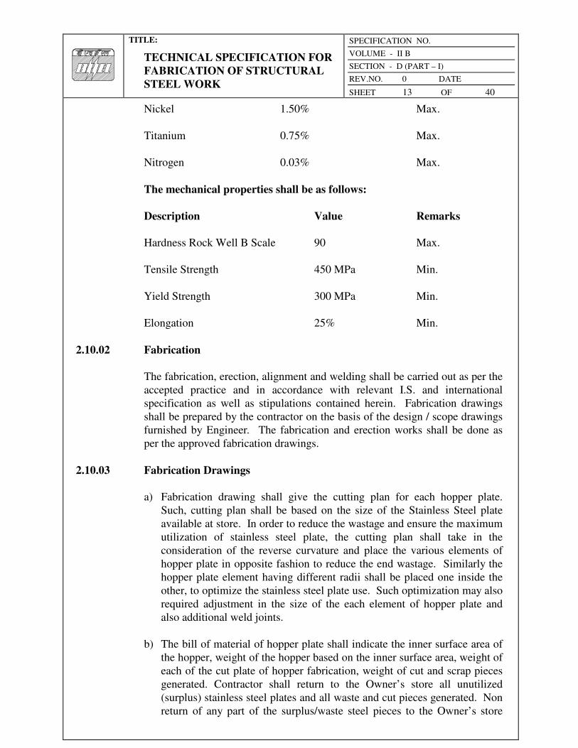
TITLE:
TECHNICAL SPECIFICATION FOR
FABRICATION OF STRUCTURAL
STEEL WORK
SPECIFICATION NO.
VOLUME - II B
SECTION - D (PART – I)
REV.NO. 0 DATE
SHEET 13 OF 40
Nickel 1.50% Max.
Titanium 0.75% Max.
Nitrogen 0.03% Max.
The mechanical properties shall be as follows:
Description Value Remarks
Hardness Rock Well B Scale 90 Max.
Tensile Strength 450 MPa Min.
Yield Strength 300 MPa Min.
Elongation 25% Min.
2.10.02 Fabrication
The fabrication, erection, alignment and welding shall be carried out as per the
accepted practice and in accordance with relevant I.S. and international
specification as well as stipulations contained herein. Fabrication drawings
shall be prepared by the contractor on the basis of the design / scope drawings
furnished by Engineer. The fabrication and erection works shall be done as
per the approved fabrication drawings.
2.10.03 Fabrication Drawings
a) Fabrication drawing shall give the cutting plan for each hopper plate.
Such, cutting plan shall be based on the size of the Stainless Steel plate
available at store. In order to reduce the wastage and ensure the maximum
utilization of stainless steel plate, the cutting plan shall take in the
consideration of the reverse curvature and place the various elements of
hopper plate in opposite fashion to reduce the end wastage. Similarly the
hopper plate element having different radii shall be placed one inside the
other, to optimize the stainless steel plate use. Such optimization may also
required adjustment in the size of the each element of hopper plate and
also additional weld joints.
b) The bill of material of hopper plate shall indicate the inner surface area of
the hopper, weight of the hopper based on the inner surface area, weight of
each of the cut plate of hopper fabrication, weight of cut and scrap pieces
generated. Contractor shall return to the Owner’s store all unutilized
(surplus) stainless steel plates and all waste and cut pieces generated. Non
return of any part of the surplus/waste steel pieces to the Owner’s store

TITLE:
TECHNICAL SPECIFICATION FOR
FABRICATION OF STRUCTURAL
STEEL WORK
SPECIFICATION NO.
VOLUME - II B
SECTION - D (PART – I)
REV.NO. 0 DATE
SHEET 14 OF 40
will call for the penal recovery at three (03) times the maximum
procurement rate for the weight of stainless steel pieces not returned to the
store.
c) In case the contractor does the cutting of the stainless steel without
approved cutting plan then all the wastage (i.e. the difference between the
weight of stainless steel plate cuts and the actual finished weight
considered for the measurement for payment) shall be subjected to the
penal recovery at the rate mentioned above.
2.10.04 Cuffing
Cutting may be affected by shearing, or by using plasma. The cut edges of all
plates shall be perfectly straight and uniform through out. Cutting shall be
done as per the cutting plan shown in the fabrication drawing. Should the
Engineer find it necessary, the edges shall be ground smooth afterwards by
contractor within the unit rates quoted by him. All the edge s shall be ground
smooth before they are welded.
2.10.05 Jointing
Welding shall join stainless steel. All weld joints (along the inclined plane)
shall be staggered. Any common welding process can weld stainless steel viz.
MIG, metal arc or plasma using the covered compatible electrodes as per IS:
5206 or by inert gas arc welding as per IS: 2811. Shielding gas shall be Argon
+ Hydrogen mixture or Argon + Oxygen mixture. However, Argon + Oxygen
mixture shall be preferred. Carbon-di-oxide mixture shall be avoided. 308L
and 315L electrodes/fillers shall be used for the welding of Stainless Steel to
Stainless Steel and Stainless Steel to Mild Steel respectively. However, the
welding process and the type of the electrodes to be used for welding shall be
as per welding procedure, as approved by the Engineer. On the basis of the
welding procedure, the Contractor shall conduct qualification test.
2.10.06 Bending
The stainless steel plates shall be subjected to cold forming and bending in
order to get the desired shape and profile.
2.10.07 Welding sequence
The type of electrodes, welding sequence, preheat and interpass temperature
and post weld heat treatment shall be as approved by the Engineer.
2.10.08 Acceptance Criteria of Fabricated Structures
The acceptance of the fabricated structure work shall depend upon correct

TITLE:
TECHNICAL SPECIFICATION FOR
FABRICATION OF STRUCTURAL
STEEL WORK
SPECIFICATION NO.
VOLUME - II B
SECTION - D (PART – I)
REV.NO. 0 DATE
SHEET 15 OF 40
dimensions and alignment, absence of distortion in the structure, satisfactory
results from the inspection and testing of the welded structure joints and the
test specimens, general workmanship being good meeting the tolerance
requirements given in IS: 7215.
2.11.00 BEARINGS
2.11.01 PTFE (Poly tetra fluorethylene) slide bearing
a) General
The bearings shall consist of upper and lower units. The upper unit shall
include a sole plate with mirror finish stainless steel facing bonded to the
bottom surface of the sole plate. The lower unit shall consist of a relevant
laminated elastomers pad surfaced with PTFE. A rigid confining medium
substructure bonds the PTFE to the pad. When the upper and lower units
are mated the stainless steel slides on the PTFE surface with an extremely
low coefficient of friction. These bearings shall be designed as per the
performance requirements. The bearing shall be of reputed make and
manufacturer as approved by Engineer, for required vertical loads, as per
the construction drawings and for a maximum displacement of ± 50 mm.
b) Material
PTFE bearing shall be sliding against highly polished stainless steel and
the coefficient of friction between them shall be less than 0.06 at 55
kg/cm². In order to prevent cold flow in the PTFE surface it shall be rigidly
bonded by a special high temperature resistant adhesive to the stainless
steel sub-strata. The stainless steel surface, which slides against the PTFE,
is mirror polished. The stainless steel shall be bonded to the top plate by
special high strength adhesive. The thickness of the stainless steel shall be
between 1.0 to 1.5mm.
The resilient bearing pad shall consist of multiple layers of lightweight
fabric impregnated with a high quality elastomer compound vulcanized
into slabs of uniform standard thickness as per the requirement. This shall
withstand vertical (compressive) load not less than 500 kg/cm² and shear
loads upto 40 kg/cm².
c) Installation
The seating area for PTFE bearing shall be prepared accurately level and
furnished with a thin layer of epoxy resin mortar. The bearing will be
placed on this layer while it is still workable and the bearing is levelled.
The bearing should not be displaced as the beam is lowered into position.
When the mortar and adhesive are fully set and the beam slightly above the

TITLE:
TECHNICAL SPECIFICATION FOR
FABRICATION OF STRUCTURAL
STEEL WORK
SPECIFICATION NO.
VOLUME - II B
SECTION - D (PART – I)
REV.NO. 0 DATE
SHEET 16 OF 40
top of the bearing. The upper surface of the bearing shall then be coated
with sufficient thickness of epoxy resin mortar so that when the beam is
lowered on to the temporary supports it comes into full contact with the
mortar and some is squeezed out. The surplus shall be troweled off and
after the mortar is fully set the temporary supports removed.
2.12.00 Storage of material
2.12.01 General
All materials shall be so stored as to prevent deterioration and to ensure the
preservation of their quality and fitness for the work. Any material, which has
deteriorated or has been damaged, shall be removed from the contractor's yard
immediately, failing which, the Engineer shall be at liberty to get the material
removed and the cost incurred thereof shall be realised from the Contractor.
The Contractor shall maintain upto date accounts in respect of receipt, use, and
balance of all sizes and sections of steel and other materials. In case the
fabrication is carried out in contractor's fabrication shop outside the plant site
where other fabrication works are also carried out, all materials meant for use
in this contract shall be stacked separately with easily identifiable marks.
2.12.02 Steel
The steel to be used in fabrication and the resulting cut-pieces shall be stored
in separate stacks off the ground section wise and lengthwise so that they can
be easily inspected, measured, and accounted for at any time. If required by the
Engineer, the materials may have to be stored under cover and suitably painted
for protection against weather.
2.12.03 Electrodes
The electrodes for electric arc welding shall be stored in properly designed
racks, separating different types of electrodes in distinctly marked
compartments. The electrodes shall be kept in a dry and warm condition if
necessary by resorting to heating.
2.12.04 Bolts, Nuts and Washers
Bolts, nuts and washers and other fastening materials shall be stored on racks
off the ground with a coating of suitable protective oil. These shall be stored
in separate gunny bags or compartments according to diameter, length, and
quality.
2.12.05 Paints
Paints shall be stored under cover in air tight containers. Paints supplied in

TITLE:
TECHNICAL SPECIFICATION FOR
FABRICATION OF STRUCTURAL
STEEL WORK
SPECIFICATION NO.
VOLUME - II B
SECTION - D (PART – I)
REV.NO. 0 DATE
SHEET 17 OF 40
sealed containers shall be used up as soon as possible once the container is
opened.
2.13.00 Quality Control
The Contractor shall establish and maintain quality control procedures for
different items of work and materials to the extent he deems necessary to
ensure that all work is performed in accordance with this specification. In
addition to the Contractor's quality control procedures, materials and
workmanship at all times shall be subjected to inspection by the Engineer or
Engineer's representative. As far as possible, all inspection by the Engineer or
Engineer’s representative shall be made at the Contractor's fabrication shop
whether located at Site or elsewhere. The Contractor shall co-operate with the
Engineer or Engineer's representative in permitting access for inspection to all
places where work is being done and in providing free of cost all necessary
help in respect of tools and plants, instrument, labour and materials required to
carry out the inspection. The inspection shall be so scheduled as to provide
the minimum interruption to the work of the Contractor.
Materials or workmanship not in reasonable conformance with the provisions
of this Specification may be rejected at any time during the progress of the
work.
The quality control procedure shall cover but not be limited to the following
items of work
a) Steel: Quality manufacturer's test certificates, test reports of representative
samples of materials from unidentified stocks if permitted to be used.
b) Rivets, Bolts, : Manufacturer's certificate, dimension checks,
Nuts & Washers material testing.
c) Electrodes : Manufacturer's certificate, thickness and quality
of flux coating.
d) Welders : Qualifying Tests
e) Welding sets : Performance Tests
f) Welds : Inspection, X-ray, Ultrasonic tests
g) Paints : Manufacturer’s certificate, physical inspection
reports
h) Galvanizing : Tests in accordance with IS 2633 - Method for
testing uniformity of coating on Zinc Coated

TITLE:
TECHNICAL SPECIFICATION FOR
FABRICATION OF STRUCTURAL
STEEL WORK
SPECIFICATION NO.
VOLUME - II B
SECTION - D (PART – I)
REV.NO. 0 DATE
SHEET 18 OF 40
Articles and IS : 4759 - Specification for Hot-
Dip Zinc coatings on Structural Steel and other
allied products.
2.14.00 Standard dimensions, forms and weights
The dimensions, forms, weights and tolerances of all rolled shapes rivets,
bolts, nuts, studs, washers etc. and other members used in the fabrication of
any structure shall, wherever applicable, conform to the requirements of the
latest relevant Indian Standards, wherever they exist, or, in the absence of
Indian Standards, to other equivalent standards.
2.15.00 Fabrication Drawings
The contractor shall within thirty (30) days after the award of the Contract
submit to the Engineer the Schedule of Fabrication and erection of structural
Steelworks, for approval. Within one week after receipt of approval on design
of any steel structure (part or full) based on the approved design. As decided
by the Engineer, six (6) copies each of some or all of the detailed fabrication
drawings will have to be submitted for approval.
The sequence of preparation of fabrication drawings shall match with the
approved fabrication and erection schedule. The above-mentioned approval for
fabrication drawings will be accorded only towards the general conformity
with the design requirements as well as specifications. The approval of
drawing however shall not relieve the contractor of his sole responsibility in
carrying out the work correctly and fulfilling the complete requirements of
contract documents.
The fabrication drawings shall include but not limited to the following:
a) Assembly drawings giving exact sizes of the sections to be used and
identification marks of the various sections.
b) Dimensional drawings of base plates, foundation bolts location etc.
c) Comparison sheets to show that the proposed alternative section, if any, is
as strong as the original sections shown on the Design Drawings.
d) Complete Bill of Materials and detailed drawings of all sections as also
their billing weights.
e) Any other drawings or calculations that may be required for the
clarification of the works or substituted parts thereof.
These drawings shall give all the necessary information for the fabrication,

TITLE:
TECHNICAL SPECIFICATION FOR
FABRICATION OF STRUCTURAL
STEEL WORK
SPECIFICATION NO.
VOLUME - II B
SECTION - D (PART – I)
REV.NO. 0 DATE
SHEET 19 OF 40
erection, and painting of the steelwork in accordance with the provisions of
this Specification. Fabrication drawings shall be made in accordance with the
best modern practice and with due regard to sequence, speed and economy in
fabrication and erection. Fabrication drawings shall give complete information
necessary for fabrication of the various components of the steelwork, including
the location, type, size, and extent of welds. These shall also clearly
distinguish between shop and field rivets, bolts, and welds and specify the
class of bolts and nuts. The drawings shall be drawn to a scale large enough to
convey all the necessary information adequately. Notes on the fabrication
drawings shall indicate those joints or groups of joints in which it is
particularly important that the welding sequence and technique of welding
shall be carefully controlled to minimize the locked up stresses and distortion.
Welding symbols used shall be in accordance with the requirements of the
Indian Standard Specification. IS: 813 - Scheme of symbols for Welding, and
shall be consistent throughout. Weld lengths called for on the drawings shall
mean the net effective length.
The Contractor shall be responsible for and shall carry out at his cost any
alterations of the work due to any discrepancies, errors or omissions on the
drawings or other particulars supplied by him, whether such drawings or other
particulars have been duly approved or not in accordance with the Contract.
3.00.00 WORKMANSHIP
3.01.00 Fabrication
3.01.01 General
All workmanship shall be equal to the best practice in modern structural shops,
and shall conform to the provisions of the Indian Standard IS: 800 - Code of
Practice for general construction in steel and other relevant Indian Standards or
equivalent.
3.01.02 Straightening Material
Rolled materials before being laid off or worked, must be clean, free from
sharp kinks, bends or twists and straight within the tolerances allowed by the
Indian Standard Specification on IS: 1552 - Specification for rolling and
cutting tolerance for hot-rolled steel products. If straightening is necessary, it
may be done by mechanical means or by the application of a limited amount of
localized heat. The temperature of heated areas, as measured by approved
methods, shall not exceed 600°C.
3.01.03 Cutting
Shearing, cropping, or sawing shall affect cutting. Use of a mechanically

TITLE:
TECHNICAL SPECIFICATION FOR
FABRICATION OF STRUCTURAL
STEEL WORK
SPECIFICATION NO.
VOLUME - II B
SECTION - D (PART – I)
REV.NO. 0 DATE
SHEET 20 OF 40
controlled gas-cutting torch may be permitted for mild steel only. Gas cutting
of high tensile steel may also be permitted provided special care is taken to
leave sufficient metal to be removed by machining, so that all metal that has
been hardened by flame is removed. Gas cutting without a mechanically
controlled torch may be permitted if special care is taken and done under
expert hand, subject to the approval of the Engineer.
To determine the effective size of members cut by gas, 3 mm shall be deducted
from each cut edge. Gas cut edges, which will be subjected to substantial
stress or which are to have weld metal deposited on them, shall be reasonably
free from gouges, occasional notches or gouges not more than 4 mm deep will
be permitted. Gouges greater than 4 mm that remain from cutting shall be
removed by grinding. All re-entrant corners shall be shaped notch free to a
radius of at least 12 mm. Shearing, cropping and gas cutting shall be clean,
reasonably square and free from any distortion.
3.01.04 Planning of edges
Planning or finishing of sheared or cropped edges of plates or shapes or of
edges gas-cut with a mechanically controlled torch shall not be required,
unless specifically required by design and called for on the drawings, included
in a stipulation for edge preparation for welding or as may be required after the
inspection of the cut surface. Surface cut with hand-flame shall generally be
ground, unless specifically instructed otherwise by the Engineer.
3.01.05 Clearances
The erection clearance for cleated ends of members connecting steel to steel
shall preferably be not greater than 2 mm at each end. The erection clearance
at ends of beams web shall be not more than 3 mm at each end, but where for
practical reasons greater clearance is necessary, suitably designed cheatings
shall be provided.
3.02.00 Riveted and bolted construction
3.02.01 Holes
Holes through more than one thickness of material for members, such as
compound stanchions and girder flanges, shall be drilled after the members are
assembled and tightly clamped or bolted together. Punching may be permitted
before assembly, if the thickness of the material is not greater than the nominal
diameter of rivet or bolt plus 3 mm subject to a maximum thickness of 16 mm
provided that the holes are punched 3 mm less in diameter than the required
size and reamed after assembly to the full diameter.
Holes for rivets or black bolts shall be not more than 1.5 mm or 2.0 mm

TITLE:
TECHNICAL SPECIFICATION FOR
FABRICATION OF STRUCTURAL
STEEL WORK
SPECIFICATION NO.
VOLUME - II B
SECTION - D (PART – I)
REV.NO. 0 DATE
SHEET 21 OF 40
(depending on whether the diameter of the rivet or bolt is less or more than or
equal to 25 mm) larger in diameter than the nominal diameter of the rivet or
black bolt passing through them.
Holes for turned and fitted bolts shall be drilled to a diameter equal to the
nominal diameter of the shank or barrel subject to a tolerance grade of BS as
specified in IS: 919. Parts to be connected shall be firmly held together by
tacking welds or clamps and the holes drilled through all the thicknesses in
one operation and subsequently reamed to size. Holes not drilled through all
thickness in one operation shall be drilled to a smaller size and reamed out
after assembly.
Holes for rivets or bolts shall not be formed by gas cutting process.
3.02.02 Assembly
All parts of riveted members shall be well pinned or bolted and rigidly held
together while riveting. Drifting to enlarge unmatching holes shall not
generally be permitted. In case drifting is permitted to a slight extent during
assembly, it shall not distort the metal or enlarge the holes. Holes that must be
enlarged to admit the rivets or bolts shall be reamed. Poor matching of holes
shall be cause for rejection .The component parts shall be so assembled that
they are neither twisted not otherwise damaged, and shall be so prepared that
the specified cambers, if any, are maintained.
Rivets shall ordinarily be hot driven, in which case their finished heads shall
be approximately hemispherical in shape and shall be of uniform size
throughout the work for rivets of the same size full, neatly finished and
concentric with he holes. Rivets shall be heated uniformly to a temperature not
exceeding 1 125°C they shall not be driven after their temperature has fallen
below 540°C.
Rivets shall be driven by power riveters, of either compression or manually
operated type, employing pneumatic, hydraulic or electric power. Hand driven
rivets shall not be allowed unless in exceptional cases specifically approved by
the Engineer. After driving, rivets shall be tight, shall completely fill the holes
and their heads shall be in full contact with the surface. In case of countersunk
rivets, the countersinking shall be fully filled by the rivet, any proudness of the
countersunk head being dressed off flush, if required.
Riveted members shall have all parts firmly drawn and held together before
and during riveting and special care shall be taken in this respect for all single
riveted connections. For multiple riveted connections, a service bolt shall be
provided in every third or fourth hole.
All loose, burnt, or otherwise defective rivets shall be cut out and replaced and

TITLE:
TECHNICAL SPECIFICATION FOR
FABRICATION OF STRUCTURAL
STEEL WORK
SPECIFICATION NO.
VOLUME - II B
SECTION - D (PART – I)
REV.NO. 0 DATE
SHEET 22 OF 40
special care shall be taken to inspect all single riveted connections. Special
care shall also be taken in heating and driving long rivets. The Contractor
shall prove the quality of riveting by cutting some rivets chosen at random by
the Engineer. No extra payment will be made to the Contractor for such
cutting and replacing. Riveting work, for any particular section or group, will
be considered satisfactory when at least 90% of the corresponding cut rivets is
found to be sound. If the ratio is below 75%, all the rivets in the particular
section or group shall be cut, removed and replaced and tested again at the
Contractor's expense. For cases between 75% and 90% the engineer shall have
the option to instruct cutting and replacing any number of further rivets at the
Contractor's cost as he deems necessary.
Bolted construction shall be permitted only in case of field connections if
called for on the Drawings and is subjected to the limitation of particular
connections as may be specified. In special cases, however, shop bolt
connections may be allowed if shown on drawing or directed by the Engineer.
Washers shall be tapered or otherwise suitably shaped, where necessary, to
give the heads and nuts of bolts a satisfactory bearing. The threaded portion of
each bolt shall project trough the nut at least one thread. In all cases the bolt
shall be provided with a washer of sufficient thickness under the nut to avoid
any threaded portion of the bolt being within the thickness of the parts bolted
together. In addition to the normal washer one spring washer or lock nut shall
be provided for each bolt for connections subjected to vibrating forces or
otherwise as may be specified on the Drawings.
3.03.00 Welded Construction
3.03.01 General
Welding shall be in accordance with relevant Indian Standards and as
supplemented in the Specification. Welding shall be done by experienced and
good welders who have been qualified by tests in accordance with IS: 817.
3.03.02 Preparation of material
Surface to be welded shall be free from loose scale, slag, rust, grease, paint,
and any other foreign material except that mill scale, which withstands
vigorous wire brushing, may remain. Joint surfaces shall be free from fins and
tears. Preparation of edges by gas cutting shall, wherever practicable, be done
by a mechanically guided torch.
3.03.03 Assembling
Parts to be fillet welded shall be brought in, as close contact as practicable and
in no event shall be separated by more than 4 mm. If the separation is 1.5 mm
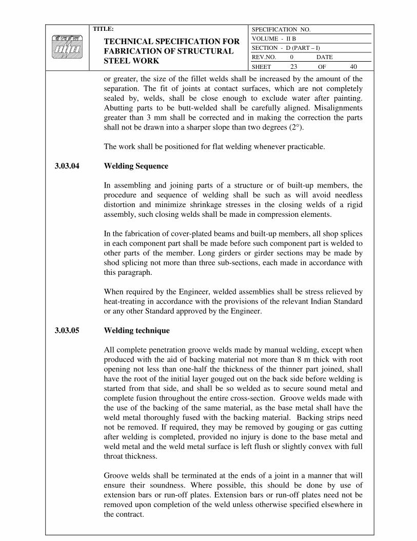
TITLE:
TECHNICAL SPECIFICATION FOR
FABRICATION OF STRUCTURAL
STEEL WORK
SPECIFICATION NO.
VOLUME - II B
SECTION - D (PART – I)
REV.NO. 0 DATE
SHEET 23 OF 40
or greater, the size of the fillet welds shall be increased by the amount of the
separation. The fit of joints at contact surfaces, which are not completely
sealed by, welds, shall be close enough to exclude water after painting.
Abutting parts to be butt-welded shall be carefully aligned. Misalignments
greater than 3 mm shall be corrected and in making the correction the parts
shall not be drawn into a sharper slope than two degrees (2°).
The work shall be positioned for flat welding whenever practicable.
3.03.04 Welding Sequence
In assembling and joining parts of a structure or of built-up members, the
procedure and sequence of welding shall be such as will avoid needless
distortion and minimize shrinkage stresses in the closing welds of a rigid
assembly, such closing welds shall be made in compression elements.
In the fabrication of cover-plated beams and built-up members, all shop splices
in each component part shall be made before such component part is welded to
other parts of the member. Long girders or girder sections may be made by
shod splicing not more than three sub-sections, each made in accordance with
this paragraph.
When required by the Engineer, welded assemblies shall be stress relieved by
heat-treating in accordance with the provisions of the relevant Indian Standard
or any other Standard approved by the Engineer.
3.03.05 Welding technique
All complete penetration groove welds made by manual welding, except when
produced with the aid of backing material not more than 8 m thick with root
opening not less than one-half the thickness of the thinner part joined, shall
have the root of the initial layer gouged out on the back side before welding is
started from that side, and shall be so welded as to secure sound metal and
complete fusion throughout the entire cross-section. Groove welds made with
the use of the backing of the same material, as the base metal shall have the
weld metal thoroughly fused with the backing material. Backing strips need
not be removed. If required, they may be removed by gouging or gas cutting
after welding is completed, provided no injury is done to the base metal and
weld metal and the weld metal surface is left flush or slightly convex with full
throat thickness.
Groove welds shall be terminated at the ends of a joint in a manner that will
ensure their soundness. Where possible, this should be done by use of
extension bars or run-off plates. Extension bars or run-off plates need not be
removed upon completion of the weld unless otherwise specified elsewhere in
the contract.
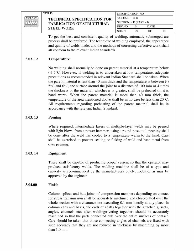
TITLE:
TECHNICAL SPECIFICATION FOR
FABRICATION OF STRUCTURAL
STEEL WORK
SPECIFICATION NO.
VOLUME - II B
SECTION - D (PART – I)
REV.NO. 0 DATE
SHEET 24 OF 40
To get the best and consistent quality of welding, automatic submerged arc
process shall be preferred. The technique of welding employed, the appearance
and quality of welds made, and the methods of correcting defective work shall
all conform to the relevant Indian Standards.
3.03. 12 Temperature
No welding shall normally be done on parent material at a temperature below
(-) 5°C. However, if welding is to undertaken at low temperature, adequate
precautions as recommended in relevant Indian Standard shall be taken. When
the parent material is less than 40 mm thick and the temperature is between (-)
5°C and 0°C, the surface around the joint to a distance of 100 mm or 4 times
the thickness of the material, whichever is greater, shall be preheated till it is
hand warm. When the parent material is more than 40 mm thick, the
temperature of the area mentioned above shall be in no case be less than 20°C.
All requirements regarding preheating of the parent material shall be in
accordance with the relevant Indian Standard.
3.03. 13 Peening
Where required, intermediate layers of multiple-layer welds may be peened
with light blows from a power hammer, using a round-nose tool, peening shall
be done after the weld has cooled to a temperature warm to the hand. Care
shall be exercised to prevent scaling or flaking of weld and base metal from
over peening.
3.03. 14 Equipment
These shall be capable of producing proper current so that the operator may
produce satisfactory welds. The welding machine shall be of a type and
capacity as recommended by the manufacturers of electrodes or as may be
approved by the engineer.
3.04.00 Finish
Column splices and butt joints of compression members depending on contact
for stress transmission shall be accurately machined and close-butted over the
whole section with a clearance not exceeding 0.1 mm locally at any place. In
column caps and bases, the ends of shafts together with the attached gussets,
angles, channels etc; after welding/riveting together, should be accurately
machined so that the parts connected butt over the entire surfaces of contact.
Care should be taken that those connecting angles of channels are fixed with
such accuracy that they are not reduced in thickness by machining by more
than 1.0 mm.
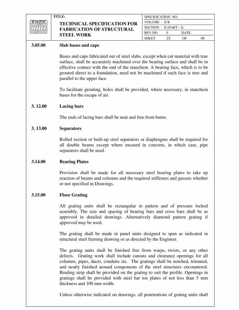
TITLE:
TECHNICAL SPECIFICATION FOR
FABRICATION OF STRUCTURAL
STEEL WORK
SPECIFICATION NO.
VOLUME - II B
SECTION - D (PART – I)
REV.NO. 0 DATE
SHEET 25 OF 40
3.05.00 Slab bases and caps
Bases and caps fabricated out of steel slabs, except when cut material with true
surface, shall be accurately machined over the bearing surface and shall be in
effective contact with the end of the stanchion. A bearing face, which is to be
grouted direct to a foundation, need not be machined if such face is true and
parallel to the upper face.
To facilitate grouting, holes shall be provided, where necessary, in stanchion
bases for the escape of air.
3. 12.00 Lacing bars
The ends of lacing bars shall be neat and free from burns.
3. 13.00 Separators
Rolled section or built-up steel separators or diaphragms shall be required for
all double beams except where encased in concrete, in which case, pipe
separators shall be used.
3.14.00 Bearing Plates
Provision shall be made for all necessary steel bearing plates to take up
reaction of beams and columns and the required stiffeners and gussets whether
or not specified in Drawings.
3.15.00 Floor Grating
All grating units shall be rectangular in pattern and of pressure locked
assembly. The size and spacing of bearing bars and cross bars shall be as
approved in detailed drawings. Alternatively diamond pattern grating if
approved may be used.
The grating shall be made in panel units designed to span as indicated in
structural steel framing drawing or as directed by the Engineer.
The grating units shall be finished free from warps, twists, or any other
defects. Grating work shall include cutouts and clearance openings for all
columns, pipes, ducts, conduits etc. The gratings shall be notched, trimmed,
and neatly finished around components of the steel structures encountered.
Binding strip shall be provided on the grating to suit the profile. Openings in
gratings shall be provided with steel bar toe plates of not less than 5 mm
thickness and 100 mm width.
Unless otherwise indicated on drawings, all penetrations of grating units shall

TITLE:
TECHNICAL SPECIFICATION FOR
FABRICATION OF STRUCTURAL
STEEL WORK
SPECIFICATION NO.
VOLUME - II B
SECTION - D (PART – I)
REV.NO. 0 DATE
SHEET 26 OF 40
be made up in split section, accurately fitted, and neatly finished. Grating units
shall be provided with all necessary clips, bolts, lock washers etc. for proper
assembly and installation on supporting steel members. Maximum deviation in
linear dimension shall not exceed 12 mm.
3.10.00 Chequered Plates
Minimum thickness of chequered plate floorings, covers etc. shall be 6 mm
O/P. Chequered plate shall be accurately cut to the required sizes and shapes
and the cut edges properly ground. Stiffeners shall be provided wherever
required from design consideration.
3.11.00 Architectural Clearances
Bearing plates and stiffener connections shall not be permitted to encroach on
the designed architectural clearances.
3.11.00 Shop connections
a) All shop connections shall be otherwise riveted or welded as specified on
the Drawings.
b) Heads of rivets on surfaces carrying brick walls shall be flattened to 10
mm thick projection.
c) Certain connections, specified to be shop connections, may be changed to
field connections if desired by the Engineer for convenience of erection
and the contractor will have to make the desired changes at no extra cost to
the exchequer.
3.13.00 Castings
Steel castings shall be annealed.
3.14.00 Shop erection
The steelwork shall be temporarily shop-erected complete or as directed by the
Engineer so that accuracy of fit may be checked before dispatch. The parts
shall be shop-erected with a sufficient number of parallel drifts to bring and
keep the parts in place. In case of parts drilled or punched using steel jigs to
make all similar parts interchangeable, the steelwork shall be shop erected in
such a way as will facilitate the check of interchange ability.
TITLE:
TECHNICAL SPECIFICATION FOR
FABRICATION OF STRUCTURAL
STEEL WORK
SPECIFICATION NO.
VOLUME - II B
SECTION - D (PART – I)
REV.NO. 0 DATE
SHEET 27 OF 40
3.15.00 Shop painting
3.15.01 General
Unless otherwise specified, steelwork, which will be concealed by interior
building finish, need not be painted; steelwork to be encased in concrete shall
not be painted. Unless specifically exempted, all other steelwork shall be
given one coat of shop paint, applied thoroughly and evenly to dry surfaces
which have been cleaned, in accordance with the following paragraph, by
brush, spray, roller coating, flow-coating or dipping as may be approved by the
Engineer.
After inspection and approval and before leaving the shop, all steelwork
specified to be painted shall be cleaned by hand-wire brushing or by other
methods of loose mill scale, loose rust, weld slag or flux deposit, dirt and other
foreign matter. Oil and grease deposits shall be removed by the solvent.
Steelwork specified to have no shop paint shall, after fabrication, be cleaned of
oil or grease by solvent cleaners and be cleaned of dirt and other foreign
material by trough sweeping with a fibre brush.
3.15.02 Inaccessible parts
Surfaces not in contact, but inaccessible after assembly, shall receive two coats
of shop paint, Positively of different colours to prove application of two coats
before assembly. This does not apply to the interior of sealed hollow sections.
3.15.03 Contact surfaces
Contact surface shall be cleaned in accordance with sub-clause 3.13.1 before
assembly.
3.15.04 Finished surfaces
Machine finished surfaces shall be protected against corrosion by a rust
inhibiting coating that can be easily removed prior to erection or which has
characteristics that make removal unnecessary prior to erection.
3.15.05 Surfaces adjacent to field welds
Unless otherwise provided for, surfaces within 50 of any field weld location
shall be free of materials that would prevent proper welding or produce
objectionable fumes while welding is being done.

TITLE:
TECHNICAL SPECIFICATION FOR
FABRICATION OF STRUCTURAL
STEEL WORK
SPECIFICATION NO.
VOLUME - II B
SECTION - D (PART – I)
REV.NO. 0 DATE
SHEET 28 OF 40
3.16.00 Galvanizing
3.16.01 General
Structural steelwork for switchyard or other structures as may be specified in
the contract shall be hot dip galvanized in accordance with the American
Society for Testing and Materials Specification ASTM-A 123 or IS: 2629 -
Recommended practice for Hot-Dip Galvanizing of Iron and steel. Where the
steel structures are required to be galvanized the field connection materials
like bolts, nuts and washers shall also be galvanized.
3.16.02 Surface Preparation
All members to be galvanized shall be cleaned, by the process of pickling of
rust, loose scale, oil, grease, slag and spatter of welded areas and other foreign
substances prior to galvanizing. Pickling shall be carried out by immersing the
steel in an acid bath containing either sulphuric or hydrochloric acid at a
suitable concentration and temperature. The concentration of the acid and the
temperature of the bath can be varied, provided that the pickling time is
adjusted accordingly.
The pickling process shall be completed by thoroughly rinsing with water,
which should preferably be warm, so as to remove the residual acid.
3.16.03 Procedure
Galvanizing shall be carried out by hot dip process in a proper and uniformly
heated bath. It shall meet all the requirements when tested in accordance with
IS: 2633 - Method for testing uniformity of coating on Zinc Coated Articles
and IS: 4759 - Specification for Hot-dip zinc coatings on Structural Steel &
other allied products.
After finishing the threads of bolts, galvanizing shall be applied over the entire
surface uniformly. The threads of bolts shall not be machined after galvanizing
and shall not be clogged with zinc. The threads of nuts may be tapped after
galvanizing but care shall be taken to use oil in the threads of nuts during
erection.
The surface preparation for galvanizing and the process of galvanizing itself,
shall not adversely affect the mechanical properties of the materials to be
galvanized. Where members are of such lengths as to prevent complete
dipping in one operation, great care shall be taken to prevent warping.
Materials on which galvanizing has been damaged shall be acid stripped and
re-galvanized unless otherwise directed, but if any member becomes damaged
after leaving been dipped twice, it shall be rejected. Special care shall be taken

TITLE:
TECHNICAL SPECIFICATION FOR
FABRICATION OF STRUCTURAL
STEEL WORK
SPECIFICATION NO.
VOLUME - II B
SECTION - D (PART – I)
REV.NO. 0 DATE
SHEET 29 OF 40
not to injure the skin on galvanized surfaces during transport, handling, and
erection. Damages, if occur, shall be made good in accordance or as directed
by the Engineer.
4.00.00 INSPECTION, TESTING, ACCEPTANCE CRITERIA AND DELIVERY
4.01.00 Inspection
Unless specified otherwise, inspection to all, work shall be made by the or
Engineer's representative at the place of manufacture prior to delivery. The
Engineer or his representative shall have free access at all reasonable times to
those parts of the manufacturer’s works which are concerned with the
fabrication of the steelwork under this Contract and he shall be afforded all
reasonable facilities for satisfying himself that the fabrication is being done
in accordance with the provisions of this Specification.
The Contractor shall provide free of charge, such labour, materials, electricity,
fuel, water, stores, tools and plant, apparatus and instruments as may be
required by the Engineer to carry out inspection and/or tests in accordance
with the Contract. The Contractor shall guarantee compliance with the
provisions of this Specification.
4.02.00 Testing and Acceptance Criteria
4.02.01 General
The Contractor shall carry out sampling and testing in accordance with the
relevant Indian Standards and as supplemented herein for the following items
at his own Cost. The Contractor shall get the specimens tested in a laboratory
approved by the Engineer and submit to the Engineer the test results in
triplicate within 3 (three) days after completion of the test.
4.02.02 Steel
All steel supplied by, the Contractor shall conform, to the relevant Indian
Standards. Except otherwise mentioned in the contract, only tested quality
steel having mill test reports shall be used. In case unidentified steel materials
are permitted to be used by the Engineer, random samples of materials will be
taken from each unidentified lot of 50 M.T or less of any particular section for
tests to conform to relevant Indian Standards. Cost of all tests shall be born by
the contractor.
All material shall be free from all imperfections, mill scales, slag intrusions,
laminations, fittings, rusts etc. that may impair their strength, durability, and
appearance.

TITLE:
TECHNICAL SPECIFICATION FOR
FABRICATION OF STRUCTURAL
STEEL WORK
SPECIFICATION NO.
VOLUME - II B
SECTION - D (PART – I)
REV.NO. 0 DATE
SHEET 30 OF 40
4.02.02 Welding
a) The weld surface shall be cleaned with steel wire brush to remove spatter
metal, slag etc. and 100% of welds shall be inspected visually for size,
length of weldment and external defects. Weld gauges shall be used for
checking weld sizes. The surface shall be clean with regular beads and free
from slags, cracks, blow-holes etc.
b) Non-destructive examination shall be carried out to determine soundness
of weldments as follows:
i) 10% at random on fillet-joints.
ii) 100% on all butt-joints.
c) Should the ND tests indicate defects like improper root penetration,
extensive blowholes, slag intrusion etc., such welds shall be back gauged,
joints prepared again and rewelded. All defects shall be rectified by the
Contractor at no extra costs.
d) All electrodes shall be procured from approved reputed manufacturers with
test certificates. The correct grade and size of electrode, which has not
deteriorated in storage, shall be used. The inspection and testing of
welding shall be performed in accordance with the provisions of the
relevant Indian Standards or other equivalents. For every 50 tones of
welded fabrication, the Engineer may ask for 1(one) test-destructive or
non-destructive including X -ray, ultrasonic test or similar, the cost of
which shall be borne by the Contractor.
4.02.04 Rivets, bolts, nuts and washers
All rivets, bolts, nuts, and washers shall be procured from M/s. Guest Keen
William Ltd. or equivalent and shall confirm to the relevant Indian Standards.
If desired by the Engineer, representative samples of these materials may have
to be tested in an approved laboratory and in accordance with the procedures
described in relevant Indian Standards. Cost of all such testing shall have to be
borne by the Contractor. In addition to testing the rivets by hammer, 2% (two
per cent) of the rivets done shall have to be cut off by chisels to ascertain the
fit, quality of material and workmanship. The removal of the cut rivets and re-
installing new rivets shall be done by the Contractor at his own cost.
4.02.05 Shop painting
All paints and primers shall be of standard quality and procured from approved
manufacturers and shall conform to the provisions of the relevant Indian
Standards.

TITLE:
TECHNICAL SPECIFICATION FOR
FABRICATION OF STRUCTURAL
STEEL WORK
SPECIFICATION NO.
VOLUME - II B
SECTION - D (PART – I)
REV.NO. 0 DATE
SHEET 31 OF 40
4.02. 12 Galvanizing
All galvanizing shall be uniform and of standard quality when tested in
accordance with IS: 2633 - Method for testing uniformity of coating on Zinc
Coated Articles and 15: 4759 - specification for Hot-Dip Zinc Coatings on
Structural Steel & other allied products.
4.03.00 Tolerance
The tolerances on the dimensions of individual rolled steel components shall
be as specified in IS: 1852 - specification for rolling and Cutting Tolerances
for Hot-rolled Steel Products. The tolerances on straightness, length etc. of
various fabricated components (such as beams and girders, columns, crane
gantry girder etc.) of the steel structures shall be as specified in IS: 721 -
Tolerances for Fabrication of Steel Structures.
4.04.00 Acceptance
Should any structure or part of a structure be found not to comply with any of
the provisions of this specification, the same shall be liable to rejection. No
Structure or part of the structure once rejected, shall be offered again for test,
except in cases where the Engineer considers the defects rectifiable. The
Engineer may, at his discretion, check some of the tests at an appropriate
laboratory at the contractors cost.
When all tests to be performed in the Contractor’s shop under the terms of this
contract have been successfully carried out, the steelwork will be accepted
forthwith and the Engineer will issue acceptance certificate, upon receipt of
which, the items will be shop painted, packed and dispatched. No item to be
delivered unless an acceptance certificate for the same has been issued. The
satisfactory completion of these tests or the issue of the certificates shall not
bind the Owner to accept the work, should it, on further tests before or after
erection, be found not in compliance with the Contract.
4.05.00 Delivery of materials
4.05.01 General
The Contractor will deliver the fabricated structural steel materials to site with
all necessary field connection materials in such sequence as will permit the
most efficient and economical performance of the erection work. The Owner
may prescribe or control the sequence of delivery of materials, at his own
discretion.
TITLE:
TECHNICAL SPECIFICATION FOR
FABRICATION OF STRUCTURAL
STEEL WORK
SPECIFICATION NO.
VOLUME - II B
SECTION - D (PART – I)
REV.NO. 0 DATE
SHEET 32 OF 40
4.05.02 Marking
Each separate piece of fabricated steelwork shall be distinctly marked on all
surfaces before delivery in accordance with the markings shown on approved
erection drawings and shall bear such other marks as will further facilitate
identification and erection.
4.05.03 Shipping
Shipping shall be strictly in accordance with the sequence stipulated in the
agreed Programme. Contractor shall dispatch the materials to the e worksite
securely protecting and packing the materials to avoid loss or damage during
transport by rail, road or water. All parts shall be adequately braced to prevent
damage in transit.
Each bundle, bale or package delivered under this contract shall be marked on
as many sides as possible and such distinct marking (all previous irrelevant
markings being carefully obliterated) shall show the following:
a) Name and address of the consignee
b) Name and address of the consignor
c) Gross weight of the package in tonnes and its dimensions
d) Identification marks and/or number of the package
e) Custom registration number, if required
All markings shall be carried out with such materials as would ensure quick
drying and indelibility.
Each component or part or piece of material when shipped, shall be indelibly
marked and/or tagged with reference to assembly drawings and corresponding
piece numbers.
Each packing case shall contain in duplicate in English a packing list pasted on
to the inside of the cover in a water-proof envelope, quoting especially -
a) Name of the Contractor
b) Number and date of the Contract
c) Name of the office placing the contract
d) Nomenclature of stores

TITLE:
TECHNICAL SPECIFICATION FOR
FABRICATION OF STRUCTURAL
STEEL WORK
SPECIFICATION NO.
VOLUME - II B
SECTION - D (PART – I)
REV.NO. 0 DATE
SHEET 33 OF 40
e) A schedule of parts or pieces, giving the parts or piece number with
reference to assembly drawings and the quantity of each.
The shipping dimensions of each packing shall not exceed the maximum
dimensions permissible for transport over the Indian Railways/Roads.
After delivery of the materials at site, all packing materials shall automatically
become the property of the Owner.
Notwithstanding anything stated hereinbefore, any loss or damage resulting
from inadequate packing shall be made good by the Contractor at no additional
cost to the Owner. When facilities exist, all shipments shall be covered by
approved Insurance Policy for transit at the cost of the Contractor.
The contractor shall ship the complete materials or part on board a vessel
belonging to an agency approved by the Owner or on rail and/or road transport
as directed. The Contractor shall take all reasonable steps to ensure correct
appraisal of freight rates, weights and volumes and in no case will the Owner
be liable to pay any warehouse, wharfage, demurrage and other charges.
If, however, the Owner has to make payment of any of the above-mentioned
charges, the amount paid will be deducted from the bills of the Contractor.
Necessary advise regarding the shipment with relevant details shall reach the
Engineer at least a week in advance.
5.00.00 INFORMATION TO BE SUBMITTED
5.01.00 With Tender
The following information is required to be submitted with the Tender:
a) Progress Schedule
The Contractor shall quote in his Tender a detailed schedule of progress of
work and total time of completion, itemizing the time required for each of
the following aspects of work.
i) Preparation and approval of fabrication drawing
ii) Procurement of Materials
iii) Fabrication and shipping of all anchor bolts
iv) Fabrication and shipping of main steelwork.
TITLE:
TECHNICAL SPECIFICATION FOR
FABRICATION OF STRUCTURAL
STEEL WORK
SPECIFICATION NO.
VOLUME - II B
SECTION - D (PART – I)
REV.NO. 0 DATE
SHEET 34 OF 40
v) Fabrication and shipping of steelwork for bunkers, tanks and/or silos as
applicable.
vi) Fabrication and shipping of all other remaining steelwork including
miscellaneous steelwork.
vii) Final date of completion of all shipments.
b) Shop
Location of the Tenderer's fabrication workshop giving details of
equipment, manpower, the total capacity, and the capacity that will be
available exclusively for this contract shall be submitted.
5.02.00 After Award
After award of the Contract the successful Tenderer is to submit the following:
a) Complete fabrication drawings, material lists, cutting lists, rive and bolt
lists, field welding schedules based on the approved design drawings
prepared by him in accordance with the approved schedule.
b) Monthly Progress Report with necessary photographs in six (6) copies to
reach the Engineer on or before the 7th day o. each month, giving the up-
to-date status of preparation of detailed shop drawings, bill of materials,
procurement of materials, actual fabrication done, shipping and all other
relevant information.
c) Detailed monthly material reconciliation statements relevant to the Work
done and reported in the Progress Report, giving the stock at hand of raw
steel, work in progress, finished materials.
d) Results of any test as and when conducted and as require by the engineer.
e) Manufacturer’s mill test report in respect of steel materials, rivets, bolts,
nuts, and electrodes as may be applicable.
6.00.00 RATES AND MEASUREMENT
6.01.00 Rates
6.01.01 The items of work in the Schedule of items describe the work in brief. The
various items of the Schedule of items shall be read in conjunction with these
specifications including amendments and additions, general conditions of
contract, special conditions of contracts, and other tender documents, if any.

TITLE:
TECHNICAL SPECIFICATION FOR
FABRICATION OF STRUCTURAL
STEEL WORK
SPECIFICATION NO.
VOLUME - II B
SECTION - D (PART – I)
REV.NO. 0 DATE
SHEET 35 OF 40
For each item of Schedule of Items, the bidder's rates shall include the
activities covered in the description of the item as well as all necessary
operations described in the Specifications.
6.01.02 The bidder's rates shall include cost of all minor details which are obviously
and fairly intended and which may not have been included in the description in
these documents but are essential for the satisfactory completion of the work.
Rates shall also include for taking all safety measures.
6.01.03 The bidder's -rates for all items of schedule of items shall include complete
cost towards plant, equipment, erection and dismantling of scaffolding, men,
materials and consumables, skilled and unskilled labour, levies, taxes,
royalties, duties, transport, storage, repair/rectification/maintenance until
handing over, contingencies, overhead and all incidental items not specifically
mentioned but reasonably implied and necessary to complete the work.
6.01.04 No claims shall be entertained, if the details shown on the `Released for
Construction’ drawings differ from those shown on the bid/tender drawings.
6.01.05 Rates shall be inclusive of all leads and lifts/elevation.
6.01.06 The bidder's rates for Structural Steel shall include for fabrication and erection,
transportation to site, preparation checking collecting and distributing of the
fabrication drawings and design calculations, erection scheme, alignment,
welding, including preheating and post heating, testing of welders, inspection
of welds, visual inspection, non destructive and special testing, rectification
and correction of defective welding works, production test plate, inspection
and testing, erection scheme, protection against damage in transit, stability of
structures, etc. The rates shall also be inclusive of providing and installing
temporary structures, transport of Owner issue material from store, return of
surplus/waste steel materials including cut pieces/waste steel, provision of
additional butt/weld joint to reduce the wastage and all other general, special,
such requirements as may be required, for the successful completion of the
work.
6.01.07 The bidder's rates for foundation bolts assembly shall include fabrication
erection, installation, and alignment of complete bolt assembly with nuts,
locknuts, anchor plates, stiffener plates, protective tape, etc. This shall also
include the cost of materials not issued by the Owner.
6.01.08 The bidders rates for application of inorganic primer shall include surface
preparation to near white metal surface by blast cleaning, abrasives, touch up
painting, suitable enclosure to avoid contamination and the necessary statutory
approval from the factory inspector/pollution control board etc. regarding the
method of blast cleaning and abrasives used, and getting approval of the
specialized agency supplying the zinc silicate primer.
TITLE:
TECHNICAL SPECIFICATION FOR
FABRICATION OF STRUCTURAL
STEEL WORK
SPECIFICATION NO.
VOLUME - II B
SECTION - D (PART – I)
REV.NO. 0 DATE
SHEET 36 OF 40
6.01.09 The bidder's rates for application of finish painting system shall include
surface preparation, application of intermediate (under) coat, finish coat and
final finish coat, and getting approval of the specialized agency supplying the
finish paint.
6.01.10 The bidder's rates for electro-forged gratings (if specified) shall include
supply, fabrication, transportation to the site, erection and alignment of factory
made electro-forged gratings, all taxes, duties thereon etc. The rates shall also
include preparation of grating design for different spans and load intensifies,
preparation of design and fabrication drawings, edge preparation, blast
cleaning followed by finish paint.
6.01.11 The bidder's rates for galvanization of factory made electro-forged gratings (if
specified) shall include the application of hot dipped galvanization as finish
over the fabricated gratings and the treatment to be given for prevention of
white storage stains, as per the technical Aspiration.
6.01.12 The bidder’s rates for permanent mild steel bolts, nuts and washers shall
include the supply and fixing of such bolts, nuts and washers in position, for
various types of Structural Steel works, as per the technical specification.
6.01.13 The bidder’s rates for high strength structural bolts, nuts and washers shall
include the supply and fixing of such bolts, nuts and washers in position, for
various types, of Structural Steel works, as per the technical specification.
6.01.14 The bidder’s rates for dismantling, additions to, alterations in and/or
modifications shall be inclusive of all operations such as lowering of material,
carriage etc., as mentioned in the technical specification. Unutilised steel
pieces cut/removed shall be returned to the project stores free of charge. Non-
return of unublized steel pieces to the Owner's store would be considered as
wastage and recovery would be affected as per the provision of contract for
structural steel consumption. This shall not include the weight of temporarily
dismantled/supported members, connected member.
6.01.15 The bidder's rates for re-erection of erection marks after additions to,
alterations in and/or modifications shall be inclusive of all operations
mentioned in technical specification for the calculated weight of the
rectified/modified erection mark rejected at site. This shall not include the
weight of temporarily dismantled/supported members, connected member. All
the operations mentioned above for restoring such members shall be carried
out at no extra cost. The work of erection of any erection mark which has not
been dismantled but have been modified/rectified before erection shall not be
paid under this item but shall be paid under relevant item of fabrication and
erection of steel work of Schedule of items for the modified weight.

TITLE:
TECHNICAL SPECIFICATION FOR
FABRICATION OF STRUCTURAL
STEEL WORK
SPECIFICATION NO.
VOLUME - II B
SECTION - D (PART – I)
REV.NO. 0 DATE
SHEET 37 OF 40
6.01.16 The bidder's rates for PTFE shall include design, supply, transportation of the
complete assembly with guides and dust protection cover and installation of
bearings in position drilling, bolting, erecting aligning etc. along with any
taxes, duties thereon etc.
6.01.17 The bidder's rates for Stainless Steel hopper (if specified) shall include
fabrication and erection, transportation to site, preparation checking collecting
and distributing of the fabrication drawings and design calculations, all other
operations mentioned in the technical specification. The rates shall also
include for erection scheme, alignment, making cutting plan, cutting, jointing,
bending, rolling, grinding, drilling, bolting, assembly, edge preparation,
welding including pre-heating, post-heating, testing of welders, inspection of
welds, inspection and testing, protection against damage in transit, stability of
structures, installation of temporary structures etc. The rates shall also be
inclusive of providing and installing temporary structures, transport of Owner
issue material from store, return of surplus / waste steel materials including cut
pieces/waste steel, provision of additional butt / weld joint to reduce the
wastage and all other general, special, such requirements as may be required,
for the successful completion of the work.
6.01.18 The bidders rates for preformed flexible open ended bellow strap of neoprene
(if specified) shall include supply and transportation, installation in position,
drilling, bolting, aligning etc. complete along with any taxes, duties thereon
etc.
6.01.19 The bidder's rates for Stainless Steel Hand Rail (if specified) shall include
complete Hand Rail including, stainless steel beading, stainless steel cleats,
stainless steel fasteners, neoprene gaskets, preparation of shop drawing but
excluding the cost of glazing. The Owner for this item of work shall supply no
material.
6.02.00 MODE OF MEASUREMENT
6.02.01 The measurement for the item of foundation bolts assembly including that of
nuts; locknuts shall be based on the calculated weight of steel installed in
Metric Tonne, corrected to second place of decimal. The weight of the
foundation bolt shall be calculated in the same way as that done for the item of
fabrication, erection, alignment of structural steel. The weight of the nut /
locknut shall be taken as per actual weight supplied by the contractor and
accepted by the Engineer.
6.02.02 The measurement for the item of fabrication, erection, alignment, welding, etc.
of structural steel work shall be based on the approved weight of steel nearest
to a Kg, by applying the unit weight as adopted at the time of issue of
structural steel on the measurements worked out as given below.

TITLE:
TECHNICAL SPECIFICATION FOR
FABRICATION OF STRUCTURAL
STEEL WORK
SPECIFICATION NO.
VOLUME - II B
SECTION - D (PART – I)
REV.NO. 0 DATE
SHEET 38 OF 40
6.02.03 For ISMB, ISMC, ISA, flats, round bars, square bars and pipes, length shall be
taken as per distance between planes normal to the axis of the member passing
through the extreme points of the section.
6.02.04 Gussets plates in trusses, and bracings, brackets plates, stiffeners, and skew
cuts if any in plates for butt welds the area shall be assumed as the minimum
circumscribed rectangle.
6.02.05 For bunker wall plates the minimum-circumscribing rectangle of the
individual plate/pieces out of which these wall plates are assembled by butt-
welding, shall be measured. Care shall be taken to ensure maximum utilization
of cut-pieces generated by providing extra butt joints (for which no extra
payment shall be made).
6.02.06 For all other plates, where the area of any notch/skew cut in the plate is less
than 0.2 sq.m. the area of the plate shall be assumed as that of the minimum
circumscribing rectangle for the purpose of measurement and calculation of
area for the purpose of payment. However, if the area of any notch/skew cuts
in a plate is more than 0.2 sq.m. the actual profile of the plate shall be
considered for the purpose of payment.
6.02.07 No deduction shall be made for the hole in the members, if the area of
individual hole is less than 0.2 sq.m. The weight shall be calculated by
deducting the area of holes, if area of individual hole is more than 0.2 sq.m.
6.02.08 All cut-pieces and scrap generated due to cutting of holes, skew-cuts of plates,
gussets, brackets, stiffeners, etc. shall be stacked separately and handed over to
the project stores without being considered for material accounting as the
circumscribing rectangle has been considered for payment.
6.02.09 The splice plate shown in the fabrication drawing or approved by the Engineer
shall only be measured for payment.
6.02.10 The weight of permanent bolts, washers and nuts and welds shall not be
included in the weights of the members. No extra payment shall be made for
welding/bolting.
6.02.11 The bolts and nuts required for erection purpose shall not be paid for and may
be taken away by the Contractor after final welding for members. Erection
boltholes left after removal of erection bolts shall be suitably plugged with
welds.
6.02.12 The measurement for the item of application of inorganic primer including
blast cleaning of steel surfaces shall be based on the weight on which the zinc
silicate primer is applied, after blast cleaning in Metric Tonne, corrected to
third place of decimal. The weight shall be the weight as approved, for

TITLE:
TECHNICAL SPECIFICATION FOR
FABRICATION OF STRUCTURAL
STEEL WORK
SPECIFICATION NO.
VOLUME - II B
SECTION - D (PART – I)
REV.NO. 0 DATE
SHEET 39 OF 40
erection mark/element of the mark painted, for payment of the item of
fabrication and erection of structural steel works.
6.02.13 The measurement for the item of application of finish primer system shall be
based on the weight on which the epoxy based finish primer is applied in
Metric Tonne, corrected to third place of decimal. The weight shall be the
weight as approved, for erection mark/element of the mark painted, for
payment of the item of fabrication and erection of structural steel works.
6.02.14 The measurement for the item of gratings shall be based on the actual weight
in Kgs, corrected to second place of decimal, as supplied by the Contractor,
and accepted by the Engineer. Nothing extra shall be payable for making
cutouts, notches, openings of any profile, trimming profiles etc. in the grating
units.
6.02.15 The measurement for the item of hot dipped galvanization of gratings shall be
based on the actual weight in Kgs, corrected to second place of decimal of
gratings galvanized by the Contractor and accepted by the Engineer.
6.02.16 The measurement for the item of permanent bolts with nuts and washers shall
be based on the actual weight in Kgs, corrected to second place of decimal, as
supplied by the Contractor and accepted by the Engineer, and as per the
approved bolts and nuts schedules.
6.02.17 The measurement for the item of High Strength Structural bolts with nuts and
washers shall be based on the actual weight in Kgs, corrected to second place
of decimal, as supplied by the Contractor and accepted by the Engineer, and as
per the approved bolts and nuts schedules.
6.02.18 The measurement for the item of the work of dismantling, additions,
alterations, reerection etc. shall be as given below
6.02.19 For dismantling, the unmodified weight of the actually dismantled erection
marks shall only be measured.
6.02.20 For the work of addition to, alteration in and / or modification of 'erection
marks' either in erected position or in the fabrication yard, measurement of
weight for payment purpose shall be calculated as the arithmetic sum of
weight of steel cut and removed from the erection mark, weight of steel
reutilised out of such cut and removed pieces and weight of additional new
steel pieces added to the erection mark.
6.02.21 For re-erection the weight of the modified erection mark shall only be
measured.
6.02.22 The weight shall be measured nearest to kg. and shall be arrived in a manner

TITLE:
TECHNICAL SPECIFICATION FOR
FABRICATION OF STRUCTURAL
STEEL WORK
SPECIFICATION NO.
VOLUME - II B
SECTION - D (PART – I)
REV.NO. 0 DATE
SHEET 40 OF 40
similar to the measurement for the item of fabrication, erection, alignment and
welding of structural steel.
6.02.23 The measurement for the item of PTFE bearings shall be based on the actual
weight in MT, corrected to third place of decimal, supplied by the contractor
and as accepted by the Engineer and as per the approved bearing schedule, for
the total vertical load carrying capacity, for all bearings.
6.02.24 The measurement for the item of stainless steel hopper shall be based on the
actual finished weight of hopper weight in Kgs, corrected to second place of
decimal. The hopper weight shall be arrived by multiplying of the inner
surface area of the hopper with the unit weight of the hopper plate.
6.02.25 The measurement for the item of flexible open-ended bellows straps of
neoprene shall be based in running meter, corrected to second place of
decimal. Bellow Straps shall be supplied as per the requirement of the
approved drawings. The measurement shall be done for the inner
circumference of the bunker on which neoprene has been fixed and for the
length supplied by the Contractor 'and as accepted by the Engineer.
6.02.26 The measurement for the item of Stainless Steel Hand Railing shall be based
in Kgs corrected to second place of decimal. The weight shall also include the
weight of Stainless Steel fasteners, Stainless Steel beading, Stainless Steel
cleats etc. The weight shall be the finished weight of Hand Rail, as accepted
by the Engineer.

TITLE:
TECHNICAL SPECIFICATION FOR
ERECTION OF STRUCTURAL
STEELWORK
SPECIFICATION NO.
VOLUME - II B
SECTION - D (PART – I)
REV.NO. 0 DATE
SHEET 1 OF 17
VOLUME: II B
SECTION - D (PART I)
SUB-SECTION – D XVIII
ERECTION OF STRUCTURAL STEELWORK

TITLE:
TECHNICAL SPECIFICATION FOR
ERECTION OF STRUCTURAL
STEELWORK
SPECIFICATION NO.
VOLUME - II B
SECTION - D (PART – I)
REV.NO. 0 DATE
SHEET 2 OF 17
C 0 N T E N T
CLAUSE NO. DESCRIPTION SHEET NO.
1.00.00 SCOPE 3
2.00.00 GENERAL 3
3.00.00 WORKMANSHIP 6
4.00.00 TESTING AND ACCEPTANCE CRITERIA 12
5.00.00 INFORMATION TO BE SUBMITTED 16
TITLE:
TECHNICAL SPECIFICATION FOR
ERECTION OF STRUCTURAL
STEELWORK
SPECIFICATION NO.
VOLUME - II B
SECTION - D (PART – I)
REV.NO. 0 DATE
SHEET 3 OF 17
SUB-SECTION – D XVIII
ERECTION OF STRUCTURAL STEELWORK
1.00.00 SCOPE
This specification covers the erection of structural steelwork including
receiving and taking delivery of fabricated structural steel materials arriving at
site, installing the same in position, painting and grouting the stanchion bases
all complete as per Drawings, this Specification and other provision of the
Contract.
2.00.00 GENERAL
2.01.00 Work to be provided for by the Contractor, unless otherwise specified in the
Contract, shall include but not be limited to the following:
a) The Contractor shall provide all construction and transport equipment,
tools, tackle, consumables, materials, labour, and supervision required for
erection of the structural steelwork.
b) Receiving, unloading, checking, and moving to storage yard at Site
including prompt attendance to all insurance matters as necessary for all
fabricated steel materials arriving at Site. The Contractor shall pay all
demurrage and/or wharfage charges etc. on account of default on his part.
c) Transportation of all fabricated structural steel materials from Site storage
yard, handling, rigging, assembling, riveting, bolting, welding and
satisfactory installation of all fabricated structural steel materials in proper
location according to approved erection drawings and/or as directed by the
Engineer. If necessary suitable temporary approach roads to be built for
transportation of fabricated steel structures.
d) Checking center lines, levels of all foundation blocks including checking
line, level, position and plumb of all bolts and pockets. Any defect
observed in the foundation shall be rectified with Engineer's approval. The
Contractor shall fully satisfy himself regarding the correctness of the
foundations before installing the fabricated steel structures on the
foundation blocks.
e) Aligning, plumbing, leveling, riveting, bolting, welding and securely fixing
the fabricated steel structures including floor gratings, chequered plates
etc. in accordance with the Drawings or as directed by the Engineer.
f) Painting of the erected steel structures.
TITLE:
TECHNICAL SPECIFICATION FOR
ERECTION OF STRUCTURAL
STEELWORK
SPECIFICATION NO.
VOLUME - II B
SECTION - D (PART – I)
REV.NO. 0 DATE
SHEET 4 OF 17
g) All minor modifications of the fabricated steel structures as directed by the
Engineer including but not limited to the following:
i) Removal of bends, kinks, twists etc. for parts damaged during transport
and handling.
ii) Cutting, chipping, filling, grinding, etc. if required for preparation and
finishing of site connections.
iii) Reaming of holes for use of higher size rivet or bolt if required.
iv) Refabrication of parts damaged beyond repair during transport and
handling or refabrication of parts, which are incorrectly fabricated.
v) Fabrication of parts omitted during fabrication by error, or
subsequently found necessary.
vi) Drilling of holes which are either not drilled at all or are drilled in
incorrect location during fabrication.
vii) Carry out tests in accordance with this specification.
2.02.00 Work by Others
No work under this Specification will be provided for by any agency other
than the Contractor unless specifically mentioned elsewhere in the contract.
2.03.00 Codes and Standards
All work under this Specification shall, unless specified otherwise, conform to
the latest revisions and/or replacements of the following or any other Indian
Standard Specification and codes of Practice of equivalent:
IS: 800 - Code of practice for general construction in steel.
IS: 456 - Code of practice for main or reinforced concrete.
2.04.00 Conformity with Designs
The Contractor will erect the entire fabricated steel structure, align all the
members, complete all field connections and grout the foundations all as per
the provisions of this specification and the sequence and the design criteria
laid down by the Engineer. All work shall conform to the provisions of this
specification and /or instructions of the engineer. The testing and acceptance
of the erected structures shall be in accordance with the provisions of this
Specifications and/or the instructions o the Engineer.

TITLE:
TECHNICAL SPECIFICATION FOR
ERECTION OF STRUCTURAL
STEELWORK
SPECIFICATION NO.
VOLUME - II B
SECTION - D (PART – I)
REV.NO. 0 DATE
SHEET 5 OF 17
2.05.00 Material
2.05.01 General
All fabricated steel structures and connection materials shall be supplied by the
Contractor to the site. The Contractor shall take delivery from railway wagons
or trucks at site, and unload the materials and perform all formalities like
checking of materials and attend to insurance matters in accordance with Sub-
Clause 2.01.00 and as specified hereinbefore.
2.05.02 Materials to conform to Indian standards
All materials required to be supplied by the Contractor under this contract
shall conform to the relevant Indian Standard specifications.
2.06.00 Storage of Materials
2.06.01 General
All material shall be so stored as to prevent deterioration and to ensure the
preservation of their quality and fitness for use in the works. Any material
which has been deteriorated or damaged beyond repairs and has become unfit
for use shall be removed immediately from the site, failing which, the engineer
shall be at liberty to get the materials removed by agency and the cost incurred
thereof shall be realised from the Contractor's dues.
2.06.02 Yard
The Contractor will have to establish a suitable yard in an approved location at
site for storing the fabricated steel structures and other raw steel materials such
as structural sections and plates as required. The yard shall have facilities like
drainage, lighting, and suitable access for large cranes, trailers, and other
heavy equipments. The yard shall be fenced all around with security
arrangement and shall be of sufficiently large area to permit systematic storage
of the fabricated steel structures without overcrowding and with suitable
access for cranes, trailers and other equipment for use in erection work in
proper sequence in accordance with the approved Programme of work.
The Tenderer must visit the site prior to submission of his tender to acquaint
himself with the availability of land and the development necessary by way of
filling, drainage, access roads, fences, sheds etc. all of which shall be carried
out by the Contractor at his own cost as directed by the Engineer.
2.06.03 Covered Store
All field connection materials, paints, cement etc. shall be stored on well
TITLE:
TECHNICAL SPECIFICATION FOR
ERECTION OF STRUCTURAL
STEELWORK
SPECIFICATION NO.
VOLUME - II B
SECTION - D (PART – I)
REV.NO. 0 DATE
SHEET 6 OF 17
designed racks and platforms off the ground in a properly covered store
building to be built at the cost of the Contractor.
2.07.00 Quality Control
The contractor shall establish and maintain quality control procedures for
different items of work and materials as may be directed by the Engineer to
assure compliance with the provisions of the Contract and shall submit the
records of the same to the Engineer. The quality control operation shall include
but not be limited to the Following items of work :
i) Erection: Lines, levels, grades, plumbs, joint characteristics including
tightness of bolts.
ii) Grouting: Cleaning and roughness of foundation, quality of materials used
for grouting, admixtures, consistency, and strength of grout.
iii) Painting: Preparation of surface for painting, quality of primers and paints,
thinners, application and uniformity of coats.
2.08.00 Taking Delivery
The Contractor shall take delivery of fabricated structural steel and necessary
connection materials from railhead/trucks as may be necessary and as directed
by the Engineer. He shall check, unload; transport the materials to his stores
for proper storing at his own cost. The Contractor shall submit claims to
insurance or other authorities and pursue the same in case of loss or damage
during transit and handling and all loss thereof shall be borne by him.
The Contractor shall also take all precautions against damage of the materials
in his custody after taking delivery and till the same are erected in place and
accepted. The Contractor shall salvage, collect, and deliver all the packing
materials to the Owner free of charge.
3.00.00 WORKMANSHIP
3.01.00 Erection
3.01.01 Plant and Equipment
The suitability and adequacy of all erection tools and plant and equipment
proposed to be used shall be thoroughly verified. They shall be efficient,
dependable, in good working condition and shall have the approval of the
Engineer.
TITLE:
TECHNICAL SPECIFICATION FOR
ERECTION OF STRUCTURAL
STEELWORK
SPECIFICATION NO.
VOLUME - II B
SECTION - D (PART – I)
REV.NO. 0 DATE
SHEET 7 OF 17
3.01.02 Method and sequence of erection
The method and sequence of erection shall have the prior approval of the
Engineer. The Contractor shall arrange for most economical method and
sequence available to him consistent with the drawings and specifications and
other relevant stipulations of the contract.
3.01.03 Temporary Bracing
Unless adequate bracing is included as a part of the permanent framing, the
erector during erecrtion shall install, free of cost to the Owne, temporary guys
and bracings where needed to secure the framing against loads such as wind or
seismic forces comparable in intensity to that for which the structure has been
designed, acting upon exposed framing as well as loads due to erection
equipment and erection operations.
If additional temporary guys are required to resist wind or seismic forces
acting upon components of the finished structure installed by others during the
course of the erection of the steel framing, arrangement for their installation by
the erector shall be made free of cost to the Owner.
The requirement of temporary bracings and guys shall cease when the
structural steel is once located, plumbed, levelled, aligned, and grouted within
the tolerances permitted under the specification and guyed and braced to the
satisfaction of the Engineer.
The temporary guys, braces, false work, and cribbing shall not be the property
of the Owner and they may be removed immediately upon completion of the
steel erection.
3.01.04 Temporary Floors for Buildings
It shall be the responsibility of the Contractor to provide free of cost planking
and to cover such floors during the work in progress as may be required by any
Act of Parliament and/or bylaws of state, Municipal or other local authorities.
3.01.05 Setting Out
Positioning and levelling of all steelwork, plumbing of stanchions and placing
of every part of the structure with accuracy shall be in accordance with the
approved Drawings and to the satisfaction of the Engineer. For heavy columns,
etc. the Contractor shall set proper screed bars to maintain proper level. No
extra payment shall be made for this.
Each tier of column shall be plumbed and maintained in a true vertical position
subject to the limits of tolerance under this Specification.

TITLE:
TECHNICAL SPECIFICATION FOR
ERECTION OF STRUCTURAL
STEELWORK
SPECIFICATION NO.
VOLUME - II B
SECTION - D (PART – I)
REV.NO. 0 DATE
SHEET 8 OF 17
No permanent field connections by riveting, bolting or shall be carried out
until proper alignment and plumbing has been attained.
3.01.06 Field Riveting
All rivets shall be heated and driven with pneumatic tools. Hand passing or
"throwing” of rivets are desirable. Any other method of conveying hot rivets
from the furnace to the driving point must be approved by the engineer. No-
cold rivets shall be driven. All other requirements of riveting including quality
and acceptance criteria shall be in accordance with the relevant portions of the
Specification for Fabrication of Structural Steelwork of the Project.
3.01.07 Field Bolting
All relevant Portions in respect of bolted construction of the Specification for
Fabrication of Structural Steelwork applicable to the Project shall also be
applicable for field bolting in addition to the following:
Bolts shall be inserted in such a way so that they may remain in position under
gravity even before fixing the nut. Bolted parts shall fit solidly together when
assembled and shall not be separated by gaskets or any other interposed
compressible materials. When assembled, all joint surfaces, including those
adjacent to the washers shall be free of scales except tight mill scales. They
shall be free of dirt, loose scales, burns, and other, defects that would prevent
solid seating of the parts. Contact surfaces within friction type joints shall be
free of oil, paint, lacquer, or galvanizing.
All high tensile bolts shall be tightened to provide, when all fasteners in the
joint are tight, the required minimum bolt tension by any of the following
methods.
a) Turn-of-nut Method
When the turn-of-nut method is used to provide the bolt tension, there
shall first be enough bolts brought to a "snug tight” condition to ensure that
the parts of the Joint are brought into good contact with each other. 'Snug
tight" is defined as the tightness attained by a few impacts of an impact
wrench or the full effort of a man using an ordinary spud wrench.
Following this initial operation, bolts shall be placed in any remaining
holes in the connection and brought to snug tightness. All bolts in the joint
shall then be tightened additionally by the applicable amount of nut
rotation specified in Table-I with tightening progressing systematically
from the most rigid part of the joint to its free edges. During this operation
there shall be no rotation of the part not turned by the wrench.
TABLE-I

TITLE:
TECHNICAL SPECIFICATION FOR
ERECTION OF STRUCTURAL
STEELWORK
SPECIFICATION NO.
VOLUME - II B
SECTION - D (PART – I)
REV.NO. 0 DATE
SHEET 9 OF 17
Bolts length not Bolt length Remarks
exceeding 8 times exceeding 8 times
dia or 200 mm dia or 200 mm
1/2 turn 2/3 turn Nut rotation is relative to
bolt regardless of the
element (nut or bolt)
being turned.
Tolerance on rotation-30°
over or under.
Bolts may be installed without hardened washers when tightening is done by
the turn -of-nut -method. However, normal washers shall be used.
Bolts tightened by the turn-of-nut method may have the outer face of the
match-marked with the protruding bolt point before final tightening, thus
affording the inspector visual means of noting the actual nut rotation. Such
marks can be made by the wrench operator by suitable means after the bolts
have been brought up snug tight.
b) Torque Wrench Tightening
When torque wrenches are used to provide the bolt tensions, the bolts shall be
tightened to the torques specified in TABLE-II (See Note below the Table).
Nuts shall be in tightening motion when torque is measured. When using
torque wrenches to install several bolts in a single joint, the wrench shall be
returned to touch up bolts previously tightened, which may have been loosened
by the tightening of subsequent bolts, until all are tightened to the required
tension.
TABLE-II
Nominal Bolt Diameter (mm) Torque to be applied
(Kg.M) for bolt class 8.8
of IS:1367
20 59.94
22 81.63
24 103.73
Note: The above torque values are approximate for providing tensions of 14.
7 T for 20 mm dia.; and 21.2 T for 24 mm dia. bolts under moderately
lubricated condition. The torque wrench shall be calibrated at least
TITLE:
TECHNICAL SPECIFICATION FOR
ERECTION OF STRUCTURAL
STEELWORK
SPECIFICATION NO.
VOLUME - II B
SECTION - D (PART – I)
REV.NO. 0 DATE
SHEET 10 OF 17
once daily to find out the actual torque required to produce the above
required tension in the bolt by placing it in a tension indicating device.
These torques shall be applied for tightening the bolts on that day with
the particular wrench.
In either of the above two methods, if required, for bolt entering and wrench
operation clearances, tightening may be done by turning the bolt while the nut
is prevented from rotating.
Impact wrenches if used shall be of adequate capacity and sufficiently supplied
with air to perform the required tightening of each bolt in approximately ten
seconds. Holes for turned bolts to be inserted in the field shall be reamed in
the field. All drilling and reaming for turned bolts shall be done only after the
parts to be connected are assembled. Tolerances applicable in the fit of the
bolts shall be in accordance with relevant Indian Standard Specifications. All
other requirements regarding assembly and bolt tightening shall be in
accordance with this sub clause.
3.01.08 Field Welding
All field assembly and welding shall be carried out in accordance with the
requirements of the specification for fabrication work applicable to the project,
excepting such provisions therein which manifestly apply to shop conditions
only. Where the fabricated structural steel members have been delivered
painted, the paint shall be removed before field welding for a distance of at
least 50 mm on either side of the joints.
3.01.09 Holes, Cutting and Fitting
No cutting of sections, flanges, webs, cleats, rivets, bolts, welds etc. shall be
done unless specifically approved and /or instructed by the Engineer.
The erector shall not cut, drill, or otherwise alter the work of other trades,
unless such work is clearly specified in the Contract or directed by the
Engineer. Wherever such work is obtain specified the Contractor shall obtain
complete information as to size, location and number of alterations prior to
carrying out any work. The Contractor shall not be entitled for any payment on
account of any such work.
3.02.00 Drifting
Correction of minor misfits and reasonable amount of reaming and cutting of
excess stock from rivets will be considered as permissible. For this, light
drifting may be used to draw holes together and drills shall be used to enlarge
holes as necessary to make connections. Reaming, that weakens the member or
makes it impossible to fill the holes properly or to adjust accurately after
TITLE:
TECHNICAL SPECIFICATION FOR
ERECTION OF STRUCTURAL
STEELWORK
SPECIFICATION NO.
VOLUME - II B
SECTION - D (PART – I)
REV.NO. 0 DATE
SHEET 11 OF 17
reaming, shall not be allowed.
Any error in shop work which prevents the proper assembling and fitting of
parts by moderate use of drift pins and reamers shall immediately be called to
the attention of the Engineer and approval of the method of correction
obtained. The use of gas cutting torches at erection site is prohibited.
3.03.00 Grouting of stanchion bases and bearings of beams and girders on stone,
brick or concrete (Plain or reinforced)
Grouting shall be carried out with Ordinary Cement grout as described below:
The mix shall be one (1) part cement and one (1) part sand and just enough
water to make it workable. The positions to be grouted shall be cleaned
thoroughly with compressed air jet and wetted with water and any
accumulated water shall be removed. These shall be placed under expert
supervision, taking care to avoid air locks. Edges shall be finished properly.
If the thickness of grout is 25 mm or more, two (2) parts of 6 mm down graded
stone chips may be added to the above noted cement-sand grout mix, if
required, by the Engineer or shown on the drawings.
No grouting shall be carried out until a sufficient number of bottom lengths of
stanchions have been properly lined, leveled, and plumbed and sufficient floor
beams are tied in position.
Whatever method of grouting is employed, the operation shall not be carried
out until the steelwork has been finally levelled and plumbed, the stanchion
bases being supported meanwhile by steel wedges, and immediately before
grouting, the space under steel shall be thoroughly cleaned.
If required by the Engineer, certain admixtures like aluminium powder,
“ironite” or equivalent, may be required to be added to the grout to enhance
certain desirable properties of the grout. Approved non-shrink pre-mixed grout
having required flowability and compressive strength may also be used with
Engineer's approval.
3.04.00 Painting after Erection
Field painting shall only be done after the structure is erected, levelled,
plumbed, aligned and grouted in its final position, tested and accepted by the
Engineer. Normally, final painting shall be done only after the floor slabs are
concreted and masonry walls are built. However, touch up painting, making
good any damaged shop painting and completing any unfinished portion of the
shop coat shall be carried out by the Contractor free of cost to the Owner. The
materials and specification for such painting in the field shall be in accordance
with the requirements of the specification for fabrication of structural

TITLE:
TECHNICAL SPECIFICATION FOR
ERECTION OF STRUCTURAL
STEELWORK
SPECIFICATION NO.
VOLUME - II B
SECTION - D (PART – I)
REV.NO. 0 DATE
SHEET 12 OF 17
steelwork applicable for the project.
Painting shall not be done in frosty or foggy weather or when humidity is such
as to cause condensation on the surfaces to be painted. Before painting of steel,
which is delivered unpainted, is commenced, all surfaces to be painted shall be
dried and thoroughly cleaned from all loose scale and rust.
All field rivets, bolts, welds, and abrasions to the shop coat shall be spot
painted with the same paint used for the shop coat. Where specified, surfaces,
which will be in contact after site assembling, shall receive a coat of paint (in
addition to the shop coat, if any) and shall be brought together while the paint
is still wet.
Surface, which will be inaccessible after field assembly shall receive the full,
specified protective treatment before Bolts and fabricated steel members who
are galvanized or otherwise treated and steel members to be encased shall not
be painted.
The final painting shall be of tow coats of Synthetics Enamel painting or
Aluminium paint of approved manufacture as per the approved “Schedule of
Painting”. The shades shall also be as per the approved schedule. Synthetic
enamel paint shall conform to IS: 2932.
3.05.00 Final cleaning up
Upon completion of erection and before final acceptance of the work by the
Engineer, the contractor shall remove free of cost all false work, rubbish and
all Temporary Works resulting in connection with the performance of his
work.
4.00.00 TESTING AND ACCEPTANCE CRITERIA
4.01.00 General
Loading tests shall be carried out on erected structures, if required by the
Engineer, to check adequacy of fabrication and/or erection. Any structure or a
part thereof found to be unsuitable for acceptance as a result of the test shall
have to be dismantled and replaced with suitable member as per the Contract
and no payment towards the cost of the dismantled portion and any connected
work shall be made to the contractor. In course of dismantling, if any damage
is done to any other parts of the structure or to any fixtures, the same shall be
made good free of cost by the Contractor, to the satisfaction of the Engineer.
The Cost of the tests specified hereinafter shall be borne by the Owner; but if
the structure fails to pass the tests, the cost of the tests shall be recovered from
the Contractor. Any extra claim due to loss of time, idle labour, etc. arising out
of these testing operations shall not be entertained, however, only reasonable
TITLE:
TECHNICAL SPECIFICATION FOR
ERECTION OF STRUCTURAL
STEELWORK
SPECIFICATION NO.
VOLUME - II B
SECTION - D (PART – I)
REV.NO. 0 DATE
SHEET 13 OF 17
and appropriate time extensions will be allowed.
The structure or structural member under consideration shall be loaded with its
actual dead load for as long a time as possible before testing and the tests shall
be conducted as indicated in the following sub-clauses 4.01.01, 4.01.02 and
4.01.03. The method of testing and application of loading shall be as approved
by the Engineer.
4.01.01 Stiffness Test
In this test, the structure or member shall be subjected, addition to its actual
dead load, to a test load equal to 1.5 times the specified superimposed load,
and this loading shall be maintained for 24 hours. The maximum deflection
attained during the test shall be within the permissible limit. If, after removal
of the test load, the member or structure does not show a recovery of at least
80 per cent of the maximum strain or deflection shown during 24 hours under
load, the test shall be repeated. The structure or member shall be considered to
have sufficient stiffness, provided that the recovery after this second test is not
less than 90 per cent of the maximum increase in strain or deflection recorded
during the second test.
4.01.02 Strength Test
The structure or structural member under consideration shall be subjected, in
addition to its actual dead load, to a test load equal to the sum of the dead load
and twice the specified superimposed load, and this load shall be maintained
for 24 hours.
In the case of wind load, a load corresponding to twice the specified wind load
shall be applied and maintained for 24 hours, either with or without the
vertical test load for more severe condition in the member under consideration
or the structure as a whole. Complete tests under both conditions may be
necessary to verify the strength of the structure. The structure shall be deemed
to have adequate strength if, during the test, no part fails and if on the removal
of the test load, the structure shows a recovery of at least 20 per cent of the
maximum deflection or strain recorded during the 24 hours under load.
4.01.03 Structure of same design
Where several structures are built to the same design and it is considered
unnecessary to test all of them, one structure, as a prototype, shall be fully
tested, as described in previous Sub-clauses, but in addition, during the first
application of the test load, particular note shall be taken of the strain or
deflection when the test load 1.5 times the specified superimposed load has
been maintained for 24 hours. This information is required as a basis of
comparison in any check test carried out on samples of the structure.

TITLE:
TECHNICAL SPECIFICATION FOR
ERECTION OF STRUCTURAL
STEELWORK
SPECIFICATION NO.
VOLUME - II B
SECTION - D (PART – I)
REV.NO. 0 DATE
SHEET 14 OF 17
When a structure of the same type is selected for a check test, it shall be
subjected, in addition to its actual dead load, to a superimposed test load, equal
to 1.5 time the specified live load, in a manner and to an extent prescribed by
the Engineer. This load shall be maintained for 24 hours, during which time,
the maximum deflection shall be recorded. The check test shall be considered
satisfactory, provided that the maximum strain or deflection recorded in the
check test does not exceed by more than 20% of the maximum strain or
deflection recorded at similar load in the test on the prototype.
4.01.04 Repair for subsequent test and use after strength tests
An actual structure which has passed the “Strength Test” as specified in Sub-
clause 4.1.2 hereinbefore and is subsequently to be erected for use, shall be
considered satisfactory for use after it has been strengthened by replacing any
distorted members and has subsequently satisfied the 'Stiffness Test' as
specified in Sub-clause 4.01.01 hereinbefore.
4.02.00 Tolerances
Some variation is to be expected in the finished dimensions of structural steel
frames. Unless otherwise specified, such variations are deemed to be within
the limits of good practice when they are not in excess of the cumulative effect
of detailed erection clearances, fabricating tolerances for the finished parts and
the rolling tolerances for the profile dimensions permitted under the
Specifications for fabrication of structural steel work applicable to this Project
and as specified below:
I. For Buildings Containing Cranes
Component Description Variation Allowed
1. 2. 3.
Main columns a) shifting of column axis
at foundation level with
respect to building line
i) In longitudinal direction i) ± 3.0 mm
ii) In lateral direction ii) ± 3.0 mm
b) Deviation of both major
column axis from vertical
between foundation and
other member connection
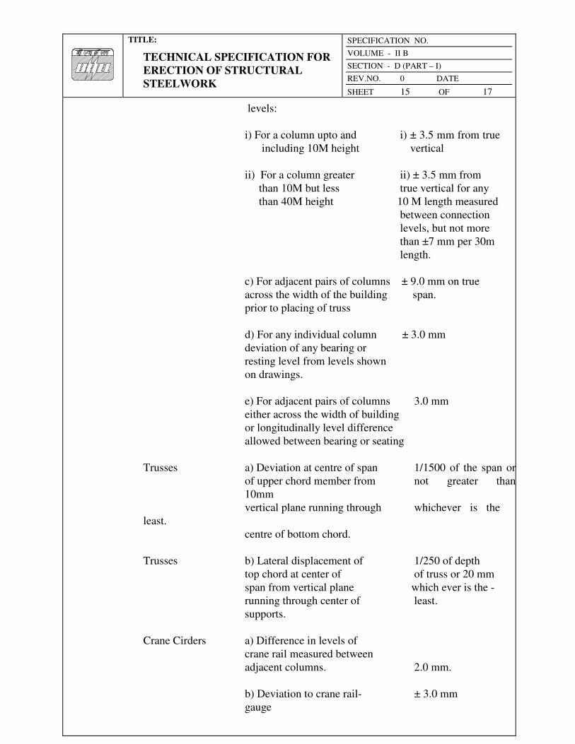
TITLE:
TECHNICAL SPECIFICATION FOR
ERECTION OF STRUCTURAL
STEELWORK
SPECIFICATION NO.
VOLUME - II B
SECTION - D (PART – I)
REV.NO. 0 DATE
SHEET 15 OF 17
levels:
i) For a column upto and i) ± 3.5 mm from true
including 10M height vertical
ii) For a column greater ii) ± 3.5 mm from
than 10M but less true vertical for any
than 40M height 10 M length measured
between connection
levels, but not more
than ±7 mm per 30m
length.
c) For adjacent pairs of columns ± 9.0 mm on true
across the width of the building span.
prior to placing of truss
d) For any individual column ± 3.0 mm
deviation of any bearing or
resting level from levels shown
on drawings.
e) For adjacent pairs of columns 3.0 mm
either across the width of building
or longitudinally level difference
allowed between bearing or seating
Trusses a) Deviation at centre of span 1/1500 of the span or
of upper chord member from not greater than
10mm
vertical plane running through whichever is the
least.
centre of bottom chord.
Trusses b) Lateral displacement of 1/250 of depth
top chord at center of of truss or 20 mm
span from vertical plane which ever is the -
running through center of least.
supports.
Crane Cirders a) Difference in levels of
crane rail measured between
adjacent columns. 2.0 mm.
b) Deviation to crane rail- ± 3.0 mm
gauge
TITLE:
TECHNICAL SPECIFICATION FOR
ERECTION OF STRUCTURAL
STEELWORK
SPECIFICATION NO.
VOLUME - II B
SECTION - D (PART – I)
REV.NO. 0 DATE
SHEET 16 OF 17
c) Relative shifting of ends 1.0 mm.
of adjacent crane rail in plan
and elevation after thermite
welding.
d) Deviation of crane rail axis ± 3.5 mm
from centre line of web.
Setting of At the time of setting of
Expansion the expansion gaps, due
gaps regard shall be taken of
the ambient temperature above
or below 30°C. The coefficient
of expansion or contraction
shall be taken as 0.000012
per °C per unit length.
iv) For Building without Cranes
The maximum tolerances for line and level of the steel work shall be ±3.0 mm
on any part of the structure. The structure shall not be Out of Plumb more
than 3.5 mm on each lox section of height and not more than 7.0 mm per 30 m
section.
These tolerances shall apply to all parts of the structure unless the drawings
issued for erection purposes state otherwise.
4.03.00 Acceptance
Structures and members have passed the tests and conform to all requirements
specified in the foregoing Sub-clause 4.01.00, 4.01.01, 4.01.02, 4.01.03 and
4.01.04 and other applicable provisions of this specification and are within the
limits of tolerances specified in Sub-clause 4.02.00 and/or otherwise approved
by the Engineer shall be treated as approved and accepted for the purpose of
fulfillment of the provisions of this contract.
5.00.00 INFORMATION TO BE SUBMITTED
5.01.00 Before Tender
5.01.01 Tentative Programme
The Tenderer shall submit a tentative programme based on the information
available in the Tender Document and visit to site indicating the structure-wise
erection schedule proposed to be maintained by the Contractor to complete the

TITLE:
TECHNICAL SPECIFICATION FOR
ERECTION OF STRUCTURAL
STEELWORK
SPECIFICATION NO.
VOLUME - II B
SECTION - D (PART – I)
REV.NO. 0 DATE
SHEET 17 OF 17
job in time in accordance with the Contract.
5.01.02 Constructional Plant and Equipment, Tools, Temporary works & manpower A
detailed list Of all constructional plant and equipment like cranes, derricks,
winches, welding sets, erection tools etc. along with their make, model,
present condition and location available with the Tenderer which he will be
able to employ on the job to maintain the progress of work in accordance with
the Contract shall be submitted along with the Tender. The total number of
each category of experienced personnel like fitters, welders, riggers etc. that he
will be able to employ on the job shall also be indicated.
5.01.03 Erection Yard
A site plan showing the layout and location of the erection yard proposed to be
established by the tenderer shall also be attached with the tender indicating the
storage space for fabricated steel materials, site-fabrication and repair shop,
covered stores, offices, locations of erection equipments and other facilities.
The Engineer shall have the right to modify the arrangement and location of
the proposed yard to suit site conditions and the Contractor shall comply with
the same without any claim whatsoever.
5.02.00 After award of the Contract
After award of the contract, the Contractor shall submit the following:
5.02.01 Detailed Programme
The Contractor shall submit a detailed erection programme within a month of
the award of the Contract for completion of the work in time in accordance
with the Contract. This will show the target programme, with details of
erection proposed to be carried out in each fortnight, details of major
equipment required, and an assessment of required strength of various
categories of workers in a proforma approved by the Engineer.
5.02.02 Fortnightly Progress Report
The Contractor shall submit fortnightly progress reports in triplicate to the
Engineer showing along with necessary photographs, 125 mm x 90 mm size,
and all details of actual achievements against the target programme specified
in Sub-clause 5.02.01 above. Any shortfall in the achievement in a particular
fortnight must be made up within the next fortnight. Along with this report, the
Contractor shall also furnish details of fabricated materials in hand at site and
the strength of his workers.
0
TITLE:
STANDARD TECHNICAL
SPECIFICATION FOR ROOF
DECKING
SPECIFICATION NO.
VOLUME - II B
SECTION - D
REV.NO. 0 DATE
SHEET 1 OF 7
VOLUME: II B
SECTION - D
SUB-SECTION – D19
ROOF DECKING
Bharat Heavy Electricals Limited Project Engineering Management

0
TITLE:
STANDARD TECHNICAL
SPECIFICATION FOR ROOF
DECKING
SPECIFICATION NO.
VOLUME - II B
SECTION - D
REV.NO. 0 DATE
SHEET 2 OF 7
C 0 N T E N T
CLAUSE NO. DESCRIPTION SHEET NO.
1.00.00 SCOPE 3
2.00.00 MATERIALS 3
3.00.00 INSTALLATION 4
4.00.00 ACCEPTANCE CRITERIA 6
5.00.00 IS CODES 6
6.00.00 RATES AND MEASUREMENTS 7

0
TITLE:
STANDARD TECHNICAL
SPECIFICATION FOR ROOF
DECKING
SPECIFICATION NO.
VOLUME - II B
SECTION - D
REV.NO. 0 DATE
SHEET 3 OF 7
ROOF DECKING
1.00.00 Scope
This section of the specification covers the supply, fabrication and erection of
profiled light gauge Metal Decks (coated and painted) as roof decking to the
main plant building and any other area as indicated in the drawings.
2.00.00 Material
2.01.01 Roof of main plant TG and Deareator bay and bunker building consists of
permanently colour coated (on exposed face) galvanized MS trough metal
sheet decking plate of approved colour over roof purlins for cast-in-situ roof
slab as per IS: 14246 and conform to class 3. Thickness of deck plate shall be
minimum 0.8mm and minimum trough depth of 44 mm and centre to centre of
the valley shall be 130mm with minimum yield strength of 250 Mpa. Silicon
modified polyester paint shall be used for permanent coating over galvanized
surface with minimum rate of galvanization 275 gm/sqm. DFT of permanent
colour coating shall be 20 microns. It shall serve as permanent shuttering for
cast-in-situ roof slab. It should have adequate strength to support weight of
green concrete and imposed load during construction. The thickness of the
deck plate shall however be designed suitably according to the spacing of roof
purlins.
3.00.00 INSTALLATION
The Contractor shall furnish all labour, equipment and materials as required
for the design, fabrication, coating, erection and fixing of the decking over
purlins, painting and for the complete performance of the work in accordance
with the construction drawings and as described herein.
The description, which follows, gives a general indication of the nature and
extent of the work but is not necessarily exhaustive and does not purport to
cover all the details/operations which will be necessary in order to carry out
the work.
3.01.00 Detailed Design of Roof Decking
The Contractor, in conjunction with the manufacturer, shall be responsible for the detailing of
the profiled decking, fittings and fixtures and shall submit with his tender
particulars of the proposed manufacturer and of the particular product
proposed for use. The detailing is to be based on typical details furnished by
the Engineer. The Contractor shall submit to the Engineer, two copies of the
general arrangement and detailed working drawings for the proposed design,
together with all calculations necessary to verify the adequacy and
completeness of the design & detailing of decking sheets, fixtures, flashings

0
TITLE:
STANDARD TECHNICAL
SPECIFICATION FOR ROOF
DECKING
SPECIFICATION NO.
VOLUME - II B
SECTION - D
REV.NO. 0 DATE
SHEET 4 OF 7
and trims. After approval he shall supply further eight copies.
The Engineer will verify the correct interpretation of his requirements but may
not necessarily check the design and details, and the Contractor shall be
entirely responsible for the accuracy of the drawings and the correctness of the
design and the suitability of the details. Manufacture of roof decking sheets
shall not commence until the necessary approval of the Engineer has been
obtained.
3.02.00 Erection & Fixing
3.02.01 Sequence of Manufacture/Erection
Cutting Schedules, delivery to site and stacking arrangements in store shall
ensure that sheets are erected in a sequence which follows that for the
manufacture. The decking sheets shall be erected using an arrangement of
sheets and joints to conform with the requirements of this specification.
Decking erection for each elevation or feature shall commence at one end only
and proceed towards the other end, in order to ensure tight fitting laps.
3.02.02 Position and Location of Laps
Side and end laps of roof decking sheets shall be located and positioned in
such a manner as to provide the maximum weather protection taking into
account the direction of the prevailing wind.
The lines formed by horizontal laps and fixing shall where possible, be
continuous and coincide with the edges of large openings in the roof.
3.02.03 Alignment of Sheets and Fixings
All roof decking sheets shall be fixed plumb and level with all fixings evenly
spaced and accurately lined. All dirt and grease shall be removed from the
surfaces of the sheets as the work proceeds.
3.02.04 Site Cutting
Approval must be obtained before the roof decking sheets are cut at site.
Generally cutting of sheets to length will not be permitted, only special cutting
and trimming for small openings shall allowed. Where possible, site cut edges
shall be concealed at laps.
3.02.05 Damaged Sheets
Distorted, blemished or water stained sheets and any other fittings shall not be
used.

0
TITLE:
STANDARD TECHNICAL
SPECIFICATION FOR ROOF
DECKING
SPECIFICATION NO.
VOLUME - II B
SECTION - D
REV.NO. 0 DATE
SHEET 5 OF 7
3.02.06 Laps
End laps and side laps to roof decking sheets shall be sufficiently large to
ensure that the decking complies with the weather tightness and other
requirements of this specification. The length of each decking sheet shall be
adjusted so that the end laps shall bear on the purlins. In no case end laps shall
not be less than 150 mm and side laps shall not be less than 53 mm.
3.02.07 End Lap Fixings
End lap fixings shall be located at least 25 mm from the end of each sheet.
3.02.08 Side Lap Fixings
The spacing of side lap fixings shall ensure compliance with this specification
regarding tightness. The spacing of these fixing screws shall not exceed
500mm. The fixing shall be located in the bottom flat of the corrugation.
3.02.09 Holes
Holes in MS decking sheets shall be punched. In case holes are drilled holes,
it is to be ensured that the holes do not go oversize due to the small thickness
of the sheeting. All drilling swarf shall be removed from the surfaces of
decking, supporting steel work, purlins etc.
3.02.10 Location and Spacing of Fixings
Fixings shall be accurately located in position in the centre of the corrugations
to ensure that the heads of bolts, nuts and washers bear squarely down on the
surface of the sheeting and are not located at the edge or on the joints in
supporting purlins.
3.02.11 Fixings
The tenderer shall submit with his tender details of the proposed method for
securing the roofing sheets to the metal purlins. The roof decking sheets are to
be fixed to the roof purlins with hex washer head white zinc plated heat treated
carbon steel self drilling / self tapping screws of minimum thread diameter of
5.6mm. These self drilling screws shall be drilled through the roofing sheets
and purlins supporting the roofing sheets. These purlins shall be suitably
spaced as per the requirement of roofing sheets and the roofing sheets shall not
sag more than span/250 for the loads likely to be imposed during concreting
and in future. The self-drilling screws are to be spaced at a maximum distance
of 390mm centre to centre along the length of the purlins and top chord of
truss. The screws are to be located preferably in the valley only and shall be
installed in accordance with the manufacturer’s recommendations using tools
0
TITLE:
STANDARD TECHNICAL
SPECIFICATION FOR ROOF
DECKING
SPECIFICATION NO.
VOLUME - II B
SECTION - D
REV.NO. 0 DATE
SHEET 6 OF 7
approved by the manufacturer which do not damage the coating of the decking
sheets.
3.03.00 Protection during Construction
Precautions shall be taken during the erection of the roof decking to ensure
that partially erected decking are protected during inclement weather and
damage at all times.
3.04.00 Damage
Any damage to coating & primer during transportation is to redone with the
similar type of coating as per the manufacturer’s specification at no extra cost
to the Owner.
4.00.00 Acceptance Criteria
The installation shall present a neat appearance and shall be checked for water
tightness. The following shall be checked :
a) Side and end laps
b) Absence of damage in the sheeting.
c) Conformity of fixings with the approved design.
5.00.00 IS Codes
All work shall be carried out as per this specification and shall conform to the
latest revision and/or replacements of the following or any other Indian
Standard (IS) Codes, unless specified otherwise. In case any particular aspect
of work is not specifically covered by Indian Standard Codes, any other
standard practice, as may be specified by the Engineer, shall be followed.
IS : 513 - Specification for cold rolled carbon steel sheets.
IS : 3618 - Specification for phosphate treatment of iron and steel for
protection against corrosion.
IS : 4431 - Specification for carbon & carbon manganese free cutting
steel.
IS : 1573 - Electroplated Coatings of zinc on iron and steel.
0
TITLE:
STANDARD TECHNICAL
SPECIFICATION FOR ROOF
DECKING
SPECIFICATION NO.
VOLUME - II B
SECTION - D
REV.NO. 0 DATE
SHEET 7 OF 7
6.00.0 RATES AND MEASUREMENTS
6.01.00 Rates
Rates shall be unit rate for complete item described in the Schedule of Items
and shall include all wastage.
6.02.00 Method of Measurement
Roofing shall be measured for net area of the work done. Profiled
sheeting (coated & painted) shall be measured in plan area of sheets and not
girthed. No deduction shall be made for openings measuring up to 0.1 sq.m. in
area. No extra shall be paid for extra labour in cutting and for wastage etc. in
making opening and cutting to size.
No payments shall be made for laps.

TITLE:
TECHNICAL SPECIFICATION FOR
SHEET WORK IN ROOF AND
SIDING
SPECIFICATION NO.
VOLUME - II B
SECTION - D | SUB-SECTION – D13
REV.NO. 00 DATE
SHEET 1 OF 6
VOLUME: II B
SECTION - D
SUB-SECTION – D13
SHEET WORK IN ROOF AND SIDING
Bharat Heavy Electricals Limited Project Engineering Management
Power Sector, BHEL House Asian Games Village Complex
Siri Fort, New Delhi-110049
TITLE:
TECHNICAL SPECIFICATION FOR
SHEET WORK IN ROOF AND
SIDING
SPECIFICATION NO.
VOLUME - II B
SECTION - D | SUB-SECTION – D13
REV.NO. 00 DATE
SHEET 2 OF 6
C 0 N T E N T
CLAUSE NO. DESCRIPTION SHEET NO.
1.00.00 SCOPE 3
2.00.00 INSTALLATION 3
3.00.00 ACCEPTANCE CRITERIA 4
4.00.00 I.S. CODES 5
5.00.00 RATES AND MEASUREMENTS 5

TITLE:
TECHNICAL SPECIFICATION FOR
SHEET WORK IN ROOF AND
SIDING
SPECIFICATION NO.
VOLUME - II B
SECTION - D | SUB-SECTION – D13
REV.NO. 00 DATE
SHEET 3 OF 6
SHEET WORK IN ROOF AND SIDING
1.00.00 SCOPE
This section covers supply, cutting & fabrication and erection of
corrugated/plain asbestos, corrugated galvanized iron, aluminum, permanently
colour coated troughed zinc-aluminium alloy coated M.S. sheet or other sheet
for covering to roof and sides at various elevations as specified.
2.00.00 INSTALLATION
2.01.00 Storage of Materials
All materials shall be stored by the Contractor in proper way to prevent all
damage.
2.02.00 Workmanship
The workmanship shall be according to best construction practice to give a
watertight finish to the satisfaction of the Engineer. Fixing of gutters and
down pipes shall be according to IS: 2527.
2.02.01 Asbestos Sheeting
Asbestos sheets of profiles as specified shall be fixed with minimum 150 mm
end lap and side laps as per manufacturer's specification. Hook bolts or J-bolts
shall be 8 mm dia. at 305 mm centres. Six (6) mm dia. galvanized iron seam
bolt and nut with G.I. flat washers and bitumen washers shall be used for
stiching ridge cappings, corner pieces, ventilators, north light curves etc.
2.02.02 C.G.I. Sheeting and Aluminium Sheeting
Side laps shall be 2 corrugations for roof and one corrugation for side sheeting.
End laps shall be minimum 150 mm for roof and 100 mm for side sheeting. In
ridges and hips where plain sheets are used, the end laps shall be minimum
100 mm. Holes in C.G.I. sheets shall preferably be made on the ground. The
sheets should be placed on purlins/trestles and holes punched in the ridge of
the corrugation from the outside inward for obtaining proper seating of limpet
washers. Sheets shall be secured to sheet framing by 8 mm dia. galvanised
iron hooks or J-bolts and maximum spacing of the bolts shall be 305 mm. The
length of the hook or J-bolts shall be to suit the sections of the bearers. Sheets
shall also be bolted at the ends at every third corrugation with 6 mm dia.
galvanized iron seam bolts and G.I. flat washers and bituminous washers.

TITLE:
TECHNICAL SPECIFICATION FOR
SHEET WORK IN ROOF AND
SIDING
SPECIFICATION NO.
VOLUME - II B
SECTION - D | SUB-SECTION – D13
REV.NO. 00 DATE
SHEET 4 OF 6
2.02.03 Fibre Glass Reinforced Plastic Sheeting
This shall be of thickness and profile as specified. Colour and light
transmittance shall be as mentioned. Where used in conjunction with C.G.I. or
asbestos sheeting, the end and side laps and fixing device shall be same as
used for general sheeting. Where used in lieu of glass, the fixing shall be by
means of timber or metal glazing beads. In all cases, the installation shall be
completely watertight and able to withstand the designed wind-pressure.
2.02.04 PERMANENT COLOUR COATED SANDWICHED INSULATED METAL
CLADDING SYSTEM
i. Troughed zinc-aluminium alloy coated (both sides) M.S. sheet having 0.6mm
minimum thickness (or high tensile steel sheet having minimum yield strength
of 350 Mpa of 0.5mm minimum thickness) shall be used on external face
(outer face) of cladding system. Weight of coating shall not be less than 150
gm/sq.m. The outer side (exposed face) shall be permanently colour coated
with Polyfluro Vinyl Coating (PVF2) of Dry Film Thickness (DFT) 20 microns
(minimum) over primer. Inner side of external sheet shall be provided with
suitable pre-coating of minimum 7 microns.
ii. Galvanised M.S. sheets of minimum 0.6mm thickness shall be used as inner
liner (internal face) of cladding system. The exposed face shall be
permanently colour coated with silicon modified polyester paint of DFT 20
microns (minimum) over primer. Inner face of external sheet shall be provided
with suitable pre-coating of minimum 7 microns. The rate of galvanization
shall not be less than 275 gm/sqm.
iii. The permanent colour coated sheet shall meet the general requirements of
IS:14246 and shall conform to class 3 for the durability.
iv. Inner sheet shall be fixed directly to side runners and Z spacers made out of at
least 2 mm thick galvanized steel sheet of grade 375 as per IS:277. Inner sheet
shall be fixed at the rate not more than 1.50M centre to centre to hold the
insulation and external sheeting. The fasteners shall be of high quality
corrosion resistant grade of self tapping / self drilling type provided with
suitable cap.
v. The insulation shall be of bonded mineral wool of minimum thickness 50mm
conforming to IS:8183, having a density of 32 Kg/cu.m. for glass wool & 48
Kg/cu.m. for rock wool.
2.02.05 PERMANENT COLOUR COATED (NON-INSULATED) METAL
CLADDING SYSTEM
i. Troughed zinc-aluminium alloy coated not less than 150 gm/sq.m M.S. sheets
having 0.6 mm minimum thickness (or High tensile steel sheet having

TITLE:
TECHNICAL SPECIFICATION FOR
SHEET WORK IN ROOF AND
SIDING
SPECIFICATION NO.
VOLUME - II B
SECTION - D | SUB-SECTION – D13
REV.NO. 00 DATE
SHEET 5 OF 6
minimum yield strength of 350 Mpa of 0.5mm minimum thickness) shall be
used for the cladding system. The outer side (exposed face) shall be
permanently colour coated with PVF2 paint of minimum DFT 20 microns over
primer and the inner side (internal face) shall be coated with same paint of
minimum DFT 12 microns over primer. These shall be fixed directly to
runners. The sheets shall meet the general requirement of IS:14246 and shall
conform to class 3 for the durability.
ii. FLASHING, CAPS, TRIM CLOSURES ETC.
All flashings, trim closures caps etc. required for the metal cladding system
shall be made out of plain sheets having same material and coating
specification as mentioned above for the outer face of the sandwiched metal
cladding.
3.00.00 ACCEPTANCE CRITERIA
The installations shall present a neat appearance and shall be checked for
water tightness. The following shall be checked:
a) Side and end laps
b) Absence of cracks, holes or damages in sheet
c) Spacing of bolts
d) Provision of double washers (G.I. and asbestos or bituminous washers)
e) Proper installation of flashing.
4.00.00 I.S. CODE
All work shall be carried out as per this specification and shall conform to the
latest revision and/or replacements of the following or any other Indian
Standard (IS) Codes, unless specified otherwise. In case any particular aspect
of work is not specifically covered by Indian Standard Codes, any other
standard practice, as may be specified by the Engineer, shall be followed.
IS: 3007 : Code of practice for laying of asbestos cement sheets.
IS: 2527 : Code of practice for fixing rainwater gutters and down
pipes for roof drainage.
IS: 1626 : Specification for asbestos cement building pipes, gutters
and fittings.

TITLE:
TECHNICAL SPECIFICATION FOR
SHEET WORK IN ROOF AND
SIDING
SPECIFICATION NO.
VOLUME - II B
SECTION - D | SUB-SECTION – D13
REV.NO. 00 DATE
SHEET 6 OF 6
IS: 277 : Specification for galvanized steel sheets (plain and
corrugated).
5.00.00 RATES AND MEASUREMENT
5.01.00 Rates
Rates shall be unit rate for complete item described in “Schedule of Items” and
shall include all wastage.
5.02.00 Measurement
Sheeting work in roof & sides shall be measured in Sq.M. for net area of the
work done. Profiled sheeting shall be measured flat and not girthed. Opening
less than 0.40 Sqm shall not be deducted. No extra shall be paid for extra
labour in cutting and for wastage etc. No payment shall be made for laps in
sheeting works.

TITLE:
STANDARD TECHNICAL
SPECIFICATION FOR PAINTING,
WHITEWASHING, POLISHING
SPECIFICATION NO
VOLUME - II B
SECTION - D
REV.NO. 0 DATE
SHEET 1 OF 12
VOLUME: II B
SECTION - D
SUB-SECTION – D11
PAINTING, WHITEWASHING, POLISHING
Bharat Heavy Electricals Limited Project Engineering Management
TITLE:
STANDARD TECHNICAL
SPECIFICATION FOR PAINTING,
WHITEWASHING, POLISHING
SPECIFICATION NO
VOLUME - II B
SECTION - D
REV.NO. 0 DATE
SHEET 2 OF 12
C 0 N T E N T
CLAUSE NO. DESCRIPTION SHEET NO.
1.00.00 SCOPE 3
2.00.00 INSTALLATION 3
3.00.00 ACCEPTANCE CRITERIA AND TESTING 10
4.00.00 I.S. CODES AND STANDARDS 11
5.00.00 RATES AND MEASUREMENTS 12
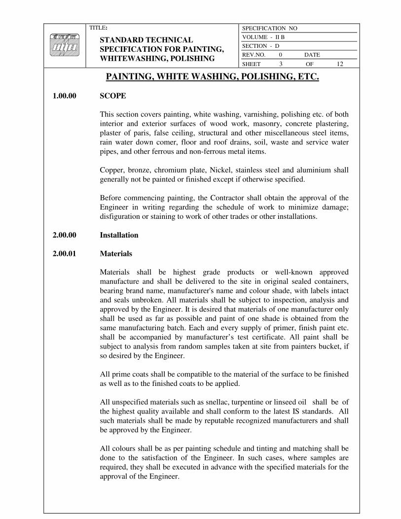
TITLE:
STANDARD TECHNICAL
SPECIFICATION FOR PAINTING,
WHITEWASHING, POLISHING
SPECIFICATION NO
VOLUME - II B
SECTION - D
REV.NO. 0 DATE
SHEET 3 OF 12
PAINTING, WHITE WASHING, POLISHING, ETC.
1.00.00 SCOPE
This section covers painting, white washing, varnishing, polishing etc. of both
interior and exterior surfaces of wood work, masonry, concrete plastering,
plaster of paris, false ceiling, structural and other miscellaneous steel items,
rain water down comer, floor and roof drains, soil, waste and service water
pipes, and other ferrous and non-ferrous metal items.
Copper, bronze, chromium plate, Nickel, stainless steel and aluminium shall
generally not be painted or finished except if otherwise specified.
Before commencing painting, the Contractor shall obtain the approval of the
Engineer in writing regarding the schedule of work to minimize damage;
disfiguration or staining to work of other trades or other installations.
2.00.00 Installation
2.00.01 Materials
Materials shall be highest grade products or well-known approved
manufacture and shall be delivered to the site in original sealed containers,
bearing brand name, manufacturer's name and colour shade, with labels intact
and seals unbroken. All materials shall be subject to inspection, analysis and
approved by the Engineer. It is desired that materials of one manufacturer only
shall be used as far as possible and paint of one shade is obtained from the
same manufacturing batch. Each and every supply of primer, finish paint etc.
shall be accompanied by manufacturer’s test certificate. All paint shall be
subject to analysis from random samples taken at site from painters bucket, if
so desired by the Engineer.
All prime coats shall be compatible to the material of the surface to be finished
as well as to the finished coats to be applied.
All unspecified materials such as snellac, turpentine or linseed oil shall be of
the highest quality available and shall conform to the latest IS standards. All
such materials shall be made by reputable recognized manufacturers and shall
be approved by the Engineer.
All colours shall be as per painting schedule and tinting and matching shall be
done to the satisfaction of the Engineer. In such cases, where samples are
required, they shall be executed in advance with the specified materials for the
approval of the Engineer.
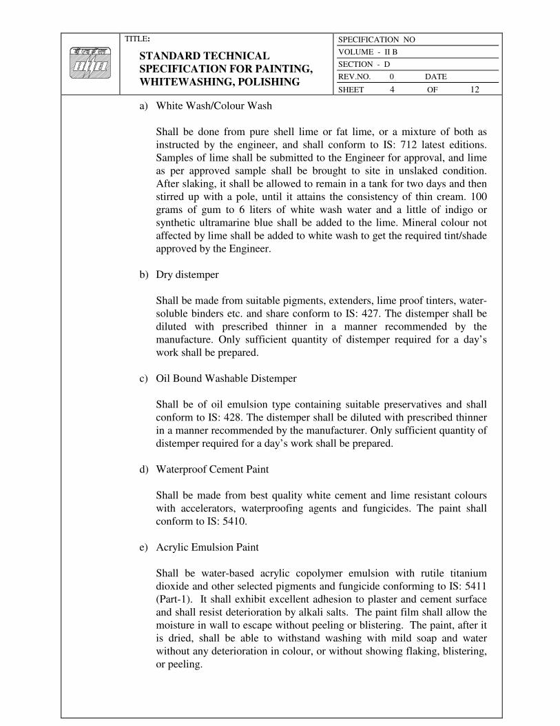
TITLE:
STANDARD TECHNICAL
SPECIFICATION FOR PAINTING,
WHITEWASHING, POLISHING
SPECIFICATION NO
VOLUME - II B
SECTION - D
REV.NO. 0 DATE
SHEET 4 OF 12
a) White Wash/Colour Wash
Shall be done from pure shell lime or fat lime, or a mixture of both as
instructed by the engineer, and shall conform to IS: 712 latest editions.
Samples of lime shall be submitted to the Engineer for approval, and lime
as per approved sample shall be brought to site in unslaked condition.
After slaking, it shall be allowed to remain in a tank for two days and then
stirred up with a pole, until it attains the consistency of thin cream. 100
grams of gum to 6 liters of white wash water and a little of indigo or
synthetic ultramarine blue shall be added to the lime. Mineral colour not
affected by lime shall be added to white wash to get the required tint/shade
approved by the Engineer.
b) Dry distemper
Shall be made from suitable pigments, extenders, lime proof tinters, water-
soluble binders etc. and share conform to IS: 427. The distemper shall be
diluted with prescribed thinner in a manner recommended by the
manufacture. Only sufficient quantity of distemper required for a day’s
work shall be prepared.
c) Oil Bound Washable Distemper
Shall be of oil emulsion type containing suitable preservatives and shall
conform to IS: 428. The distemper shall be diluted with prescribed thinner
in a manner recommended by the manufacturer. Only sufficient quantity of
distemper required for a day’s work shall be prepared.
d) Waterproof Cement Paint
Shall be made from best quality white cement and lime resistant colours
with accelerators, waterproofing agents and fungicides. The paint shall
conform to IS: 5410.
e) Acrylic Emulsion Paint
Shall be water-based acrylic copolymer emulsion with rutile titanium
dioxide and other selected pigments and fungicide conforming to IS: 5411
(Part-1). It shall exhibit excellent adhesion to plaster and cement surface
and shall resist deterioration by alkali salts. The paint film shall allow the
moisture in wall to escape without peeling or blistering. The paint, after it
is dried, shall be able to withstand washing with mild soap and water
without any deterioration in colour, or without showing flaking, blistering,
or peeling.

TITLE:
STANDARD TECHNICAL
SPECIFICATION FOR PAINTING,
WHITEWASHING, POLISHING
SPECIFICATION NO
VOLUME - II B
SECTION - D
REV.NO. 0 DATE
SHEET 5 OF 12
f) Synthetic Enamel Paint
Shall be made from synthetic resins and drying oil with rutile titanium
dioxide and other selected pigments to give a smooth, hard, durable and
glossy finish to all exterior and resist interior surfaces. White and pastel
shades shall not yellowing and darkening with aging. The paint shall
conform to IS: 2932 and IS: 2933.
g) Aluminium Paint
Shall be in two pack containers and shall resist weathering. The paint shall
conform to IS: 2339.
h) Varnishing
Shall be best quality alkyd varnish suitable for brushing over the tint of
paint or light natural wood and shall not darken or yellow with age.
i) French Polish
Shall be made from best quality shellac, denatured spirit and other suitable
alcohol soluble ingredients and made by a well known approved
manufacturer. The material shall conform to IS: 348.
French polish shall not be used on bare wood it shall only be used as
finishing coat on wood after the woods pretreated with a liquid wood filler
conforming to IS: 345 is applied and rubbed out.
j) Bitumen paint (black bituminous anti-corrosive paint)
Bitumen based anti-corrosive paint conforming to IS: 158 shall be used.
2.00.02 Storage
The Contractor shall arrange for safe and proper storage of all materials and
tools. The storage space if allotted within the building shall be adequately
protected from damage, disfigurement, & stains. Paint shall be kept covered at
all times and mixing shall be done in suitable containers. All necessary
precautions shall be taken by the contractor to prevent fire.
2.01.00 Preparation of surface
Before starting the work the Contractor shall obtain the approval of the
Engineer regarding the soundness & readiness of the surface to be painted on.

TITLE:
STANDARD TECHNICAL
SPECIFICATION FOR PAINTING,
WHITEWASHING, POLISHING
SPECIFICATION NO
VOLUME - II B
SECTION - D
REV.NO. 0 DATE
SHEET 6 OF 12
2.01.02 Wood
All surfaces shall be free from, dirt and loose or peeling paints. The surface
shall be rubbed down smooth. All nails & screws shall be sunk below the
surface and filled with putty after applying an under coat. Small knots that do
not justify cutting and sap streaks shall be covered with minimum 2 coats of
pure shellace coating applied thinly & extended 25 mm beyond the area. All
large, loose, or resinous knots shall be removed and filled with sound wood.
All work shall be done as per IS: 2338.
2.01.02 Masonry, Concrete, and Plastered Surface
Surface shall be free from all oil, grease, efflorescence, mildew, loose paint, or
other foreign and loose materials. Masonry cracks shall be cleaned out and
patch filled with mortar similar to the original surface and uniformly textured.
Where this type of resurfacing may lead to the finishing paint being different
in shade from, the original surfaces, the resurfaces area shall be treated with
minimum one coat of cement primer, which should be continued to the
surrounding area for a distance of minimum 100 mm.
Surface with Mildew or Efflorescence shall be treated as below:
All mildewed surfaces shall be treated with an approved fungicide such as
ammoniacal wash consisting of 7g of copper carbonate dissolved in 80ml
liquor ammonia and diluted to water, or 2.5 percent magnesium silicofluoride
solution and allowed to dry thoroughly before paint is applied.
2.01.03 Metal
The surface preparation shall be done in accordance with IS:1477(Part-1)
‘Code of practice for painting of ferrous metals in building’ and as directed by
Engineer. All metal surfaces shall be absolutely clean, dry, and free from rust,
scales, weld slag, flux deposit, wax, grease, dried soap films, foreign matters
like cement mortar etc and free from existing loose red oxide zinc chromate
primer and should be removed by means of wire brushes, hand scrappers, sand
paper, emery cloth, emery papers, or by mechanical power tools etc. or as
directed by Engineer. For exposed chemical resistant paints, surfaces shall be
blast cleaned to near white metal. All galvanized iron surfaces shall be
pretreated with a compatible primer according to the manufacturer's direction.
Any abrasion in shop coat shall be touched up with the same quality of paint as
the original coat. The actual painting work should be commenced only after
obtaining clearance from the Engineer regarding proper cleaning of the
surface.

TITLE:
STANDARD TECHNICAL
SPECIFICATION FOR PAINTING,
WHITEWASHING, POLISHING
SPECIFICATION NO
VOLUME - II B
SECTION - D
REV.NO. 0 DATE
SHEET 7 OF 12
2.02.00 Application
2.02.01 General
The method of application shall be as recommended by the manufacturer. In
case of selection of special shades and colour (not available in standard
shades) the Contractor shall mix different shades and prepare test panels of
minimum size 1 meter square as per instruction of the Engineer and obtain his
approval prior of application of finishing paints.
Proper tools and implements shall be used. Scaffoldings used shall be
independent of the surface to be painted to avoid shade differences of the
freshly repaired anchor notes.
Painting shall be done by skilled labours in a workmanlike manner. All
materials shall be evenly applied so as to free of sags, runs, crawls, or other
defects. All coats shall be of proper consistency. In case of application by
brush, no brush marks shall be visible. The brushes shall be clean and in good
condition before application of paint.
All priming undercoat for painting shall be applied by brush only, and rollers
spray equipments etc. shall not be used.
No work shall be done under conditions that are unsuitable production of good
results. No painting shall be done when plastering is in progress or is drying.
Application of paint, which seals the surfaces to moisture shall only be done
after the moisture on and below the surface has dried out.
All coats shall be thoroughly dry before succeeding coat is applied. Coats of
painting as specified are intended to cover surfaces perfectly. In case the
surface is not covered property by applying the specified number of coats,
further coats shall be applied by the Contractor when so desired by the
Engineer.
All primers and undercoats shall be tinted to approximate the colour of the
finishing coats. Finished coats shall be of exact colour and shade as per
approved samples and all finish shall be uniform in colour and texture. All
parts of mouldings and ornaments shall be left clean and true to finish.
Painting on ferrous metal surface shall, be done as per IS: 1477 (Part I & 2).
The total dry thickness of film should not be less than 120 Micron.
2.02.02 White Washing
The surface where white washing is to be applied shall be cleared of all loose
materials and dirt. All holes and irregularities of the surface shall be filled up

TITLE:
STANDARD TECHNICAL
SPECIFICATION FOR PAINTING,
WHITEWASHING, POLISHING
SPECIFICATION NO
VOLUME - II B
SECTION - D
REV.NO. 0 DATE
SHEET 8 OF 12
with lime putty and shall be allowed to dry up before white washing.
One coat of whitewash shall consist of one stroke from top downwards,
another from bottom upwards over the first stroke and another from left to
right before the previous one dries up. Second coat shall be applied and in case
the Engineer feels that one or more coats are required the Contractor shall do
so without any extra cost to the Owner. No brush marks shall show on the
finished surface.
2.02.03 Dry Distemper
New plastered surface shall be allowed to dry for at least two months. New
lime or lime cement plastered surface shall be washed with a solution of 1 part
Vinegar to 12 parts water or 1:50 sulphuric acid solution and for 24 hours after
which the wall shall be thoroughly washed with clean water. For cement-
plastered surface, the surface shall be washed with solution of 100 gms. of
zinc sulphate to 1 litre of water and allowed to dry.
Dry distempering shall be done as per manufacturers instruction. In applying
the distempers the brush, should first be applied horizontally and immediately
crossed off perpendicularly. Brushing shall not be continued too long,
otherwise brush marks may result.
2.02.04 Oil bound washable distemper
The distemper shall be applied after surface is primed with an alkali resistant
primer, and followed by minimum two coats of oil bound washable distemper
all as per manufacturer's instruction.
2.02.05 Waterproof Cement Paint
Surface to be coated with cement paint shall be washed and brushed down. As
soon as the moisture has disappeared, the surface shall be given one coat of
paint. Care shall be taken so that the paint does not dry out too rapidly. After 4
to 6 hours, the water shall be sprinkled over the surface to assist curing and
prevent cracking. After the first coat has dried (24 to 48 hours) the second coat
shall be applied in a similar manner. The finished surface shall be kept moist
by occasional sprinkling with water for seven days after painting.
2.02.06 Acrylic Emulsion Paint
Paint shall be applied after providing one coat of cement primer solvent of
approved quality and primer shall be conform to IS: 109. Lime gauged cement
plastered surfaces shall not be painted for at least one month after plastering.
A sample patch shall be painted to check alkali reaction if so desired by the
Engineer. Painting shall be done strictly as per manufacturer's specification.

TITLE:
STANDARD TECHNICAL
SPECIFICATION FOR PAINTING,
WHITEWASHING, POLISHING
SPECIFICATION NO
VOLUME - II B
SECTION - D
REV.NO. 0 DATE
SHEET 9 OF 12
2.02.07 Synthetic Enamel Paint
Shall be applied on properly primered surface. Subsequential coat shall not be
applied till the previous coat is dry. The previous shall be lightly sand papered
for better adhesion of subsequent coats.
2.02.08 Aluminium Paint
The paint, supplied in two pack containers shall be mixed and applied strictly
as per manufacturer's direction. When more than one coat of paint is required
or indicated, the next coat shall only be applied after the previous coat become
hard dry.
2.02.09 Clear Synthetic Varnish
The Varnish shall be applied on wood surface after (a) filling, (b) staining &
(c) sealing operations are carried out. The application of a combination of filler
and stain shall not be permitted.
For the finishing coats of varnish, the surface shall be allowed to dry and be
rubbed down lightly, wiped off and allowed to dry. Careful attention to
cleanliness is required for varnishing. All dust and dirt shall be removed from
the surface as well as from the neighbourhood. Damp atmosphere and draughts
shall be avoided, and exposure to extreme heat or cold & dampness shall not
be allowed.
The varnish shall be applied liberally with a brush and spread evenly over a
portion of the surface with light strokes to avoid frothing. It shall be allowed to
flow on white the next section is being laid on excess varnish shall then be
scrapped off the brush and the first section be crossed, recrossed and then laid
off lightly. The varnish once it has begun to set shall not be retouched. In case
of any mistake in application, the varnish shall be removed and the work
started afresh.
The varnish shall be minimum of two coats, with the first coat being a flatting
varnish. This shall be allowed to dry hard and be flatted down, before applying
the next coat. Sufficient time must be allowed between coats to get a hard dry
surface before next coat is applied. All work shall be as per relevant IS Code.
2.02.10 French polish
All unevenness of the surface shall be rubbed down to smoothness with sand
paper and the surface shall well dusted .The pores in the shall be filled up with
a paste of whitening in water or methylated spirit with a suitable pigment like
burnt siemme or umber.

TITLE:
STANDARD TECHNICAL
SPECIFICATION FOR PAINTING,
WHITEWASHING, POLISHING
SPECIFICATION NO
VOLUME - II B
SECTION - D
REV.NO. 0 DATE
SHEET 10 OF 12
After application of the filler paste, the French polish shall be applied with a
pad of woollen cloth covered by a fine cloth. The pad shall be moistened with
polish and rubbed hard on the surface in a series of overlapping circles so that
the polish is sparingly but uniformly applied over the entire area to give an
even surface. A trace of linseed oil may be used on the pad for case of
application. The surface shall be allowed to dry before further coats are
applied in the same manner. To finish off, the pad shall be covered with a
fresh piece of clean fine cloth, slightly damped with methylated spirit, and
rubbed lightly and quickly with circular motions to leave the finished surface
with a uniform texture and high gloss.
2.02.11 Chemical Resistant Paint
For chemical resistant paints, epoxy, chlorinated rubber, or vinyl butryl paint
system shall be used. Manufacturer's recommendation shall be followed
regarding the paint system, exposed to moderately to severe corrosive
condition and subject to acid/alkali spillage & fumes, shall be followed.
2.03.00 Protection
Furniture and other movable objects, equipment, fittings and accessories shall
be moved, protected and replaced upon completion of work. All stationary
equipment shall be well covered so that no paint can fall on them. Work
finished by other agencies shall be well protected. All protections shall be
done as per instructions of the Engineer.
2.04.00 Cleaning up
In addition to provisions in general conditions the Contractor shall, upon
completion of painting etc. remove all marks and make good surfaces, where
paint has been splashed or splattered, including all equipment, fixtures, glass,
furniture, fittings etc. to the satisfaction of the Engineer.
3.00.00 ACCEPTANCE CRITERIA AND TESTING
a) All painted surfaces shall be uniform and pleasing in appearance.
b) All varnished surfaces shall be of uniform texture and high glossy finish.
c) The colour, texture etc. shall match exactly with those of approved samples.
d) All stains, splashes, and splatters of paints and varnishes shall be removed
from surrounding surfaces.
TITLE:
STANDARD TECHNICAL
SPECIFICATION FOR PAINTING,
WHITEWASHING, POLISHING
SPECIFICATION NO
VOLUME - II B
SECTION - D
REV.NO. 0 DATE
SHEET 11 OF 12
Testing
a) As, each part of the work is under progress, i.e. preparation of surface,
providing primer, providing different coats of finishing paints, it shall be
passed by the Engineer. Variation from the drawings or specification or
standard etc. shall not be accepted. The Contractor shall ascertain from
the Engineer as to which parts will be inspected and passed from time to
time. The Contractor shall provide all necessary arrangement for
inspection of the painting work during its different working phase. The
Contractor shall provide necessary scaffolding, approach for inspection
of the above as per direction and satisfaction of the Engineer. All the
necessary cost for scaffolding, approach, platform, lighting arrangement
testing and inspection shall be borne by the Contractor. Such inspection
and testing will not, however, exonerate the Contractor from his
responsibilities for proper workmanship, material etc.
b) The Contractor shall carry out all sampling and necessary testing in
accordance with the relevant Indian Standards and shall conduct such
tests as called for by the Engineer. Where no specific testing procedure is
mentioned in the relevant codes, the tests shall be carried out as per the
prevalent accepted Engineering practice as per the direction of the
Engineer. Tests shall be done in a laboratory, approved by the Engineer,
and cost of testing shall be borne by the contractor.
c) Material/workmanship unsuitable for acceptance shall he removed and
replaced by the Contractor. The work shall be redone as per
Specification of the contract and direction of the Engineer without extra
cost to owner.
4.00.00 I.S. CODE
All work shall be carried out as per this specification and shall conform to the
latest revision and/or replacements of the following or any other Indian
Standard (IS) Codes, unless specified otherwise. In case any particular aspect
of work is not specifically covered by Indian Standard Codes, any other
standard practice, as may be specified by the Engineer, shall be followed.
IS: 348 Specification for French polish
IS: 427 Specification for Distemper, dry colour as required.
IS: 428 Specification for Distemper oil emulsion, colour as required.
IS: 1477 Code of Practice for painting of ferrous metal
(I & II) in buildings.
IS: 2338 Code of Practice for finishing of wood and
TITLE:
STANDARD TECHNICAL
SPECIFICATION FOR PAINTING,
WHITEWASHING, POLISHING
SPECIFICATION NO
VOLUME - II B
SECTION - D
REV.NO. 0 DATE
SHEET 12 OF 12
(I & II) wood based materials.
IS: 2339 Specification for Aluminium, Paints for general purposes in
dual containers.
IS: 2395 Code of Practice for painting concrete, masonry, and Plaster
surface.
IS: 2932 Specification for enamel, exterior type-1.
IS: 5410 Specification for cement paint, colour as required.
5.00.00 RATES AND MEASUREMENT
5.01.00 Rates
Rates shall be unit rates for complete items described in the “Schedule of
Items”.
Rate shall include cleaning, preparation of surface, supply and application of
primer, painting and providing all protection and scaffolding required at site.
5.02.00 Measurements
Painting over the concrete/masonry/wooden surface shall be measured net (on
the surface area on which it is applied) in Sqm.
No deduction shall be made for opening not exceeding 0.5 Sqm and ends of
beams, joints, etc. also no payment shall be made for reveals, jams, soffits, sill
of these openings.
50% deduction shall be made for opening exceeding 0.5 Sqm but not
exceeding 3.0 Sqm each and no addition shall be made for reveals, jams,
soffits, sills etc.
In case of opening exceeding 3.0 Sqm each, deduction shall be made for
opening but jams, soffits, and reveals shall be measured and paid for.
Corrugated surfaces shall be measured flat and measured area shall be
increased by 15%.
Painting of structural steel works shall be measured in M.T. unless specified
otherwise.
TITLE:
STANDARD TECHNICAL
SPECIFICATION FOR
MISCELLANEOUS METAL
SPECIFICATION NO
VOLUME - II B
SECTION - D
REV.NO. 0 DATE
SHEET 1 OF 9
VOLUME: II B
SECTION - D
SUB-SECTION – D8
MISCELLANEOUS METAL
Bharat Heavy Electricals Limited Project Engineering Management
TITLE:
STANDARD TECHNICAL
SPECIFICATION FOR
MISCELLANEOUS METAL
SPECIFICATION NO
VOLUME - II B
SECTION - D
REV.NO. 0 DATE
SHEET 2 OF 9
C 0 N T E N T
CLAUSE NO. DESCRIPTION SHEET NO.
1.00.00 SCOPE 3
2.00.00 INSTALLATION 3
3.00.00 ACCEPTANCE CRITERIA 7
4.00.00 IS CODES 8
5.00.00 RATES AND MEASUREMENTS 8

TITLE:
STANDARD TECHNICAL
SPECIFICATION FOR
MISCELLANEOUS METAL
SPECIFICATION NO
VOLUME - II B
SECTION - D
REV.NO. 0 DATE
SHEET 3 OF 9
MISCELLANEOUS METAL
1.00.00 SCOPE
This section covers supply, fabrication and erection of miscellaneous metal
items of light nature in gates, balcony and stair hand rails, structural works,
ladders, hangers, masonry anchors, anchor bolts, fasteners, chain link fencing,
barbed wire fencing etc. as specified or shown on drawing or as instructed by
the Engineer. The above items shall be of fabricated or cast of mild steel,
aluminium, brass, cast iron, M.S.& galvanized M.S. sheets, aluminium sheets,
expanded metal, wire mesh as shown on drawings or specified.
2.00.00 INSTALLATION
2.01.00 Fabrication/casting
2.01.01 General
All work shall be done according to approved shop drawings. All workmanship
shall be equal to the best practice in modern structural or foundary shop.
2.01.02 Shop Connections
a) All shop connections shall be riveted or welded except when noted
otherwise on drawings.
b) Welding of steel shall be done in accordance with IS: 816.
c) Welding of aluminium shall be done accordance with IS: 2812, “Arc
welding of Aluminium and Alloys.” Special care shall be taken to grind
smooth all welded surface that shall remain exposed to view. Welds shall
be electrically continuous if so required by the Engineer.
2.01.03 Shop Coat
Before leaving the shop, all metal work shall be thoroughly cleaned by
effective means of all loose mill seals, rust and foreign matter. Except where
encased in concrete, all steelwork shall be given one coat of approved metal
protective paint, applied be brush thoroughly and evenly, well worked into
joints and other open spaces. All paint shall be applied to dry surfaces. When
specified steel work shall be galvanised or painted with a coat of zinc
chromate primer. Aluminium surfaces, which shall come in contact with
masonry, shall be given one coat of bituminous paint.
TITLE:
STANDARD TECHNICAL
SPECIFICATION FOR
MISCELLANEOUS METAL
SPECIFICATION NO
VOLUME - II B
SECTION - D
REV.NO. 0 DATE
SHEET 4 OF 9
2.02.00 Erection
2.02.01 Bracing
The Contractor shall provide all necessary temporary guys and braces to
ensure alignment and stability of the members and to take care of all loads to
which the structure may be subjected, including erection of equipment and
operation of the same.
2.02.02 Temporary Bolting-Up
As erection proceeds the Contractor shall plum up and level all members and
shall securely bolt up to take care of all dead load, wind load and erection
stresses. Wherever erection equipment or other loads are carried by members
during erection, proper provision shall be made to take care of the stresses
resulting from the same.
2.02.03 Turned Bolt
For field connections where bolting is specified, holes for the turned bolts may
be reamed in the field, if required. All drilling or reaming for turned bolts
shall be done after the parts to be connected are assembled.
2.02.04 Welding
Where specified on drawings, welding shall be done in accordance with IS:
816 for steel and IS: 2812 for Aluminium & Alloys.
2.02.05 Cutting and Fitting
No cutting of sections, flanges, webs of angles shall be done without the
approval of the Engineer. Where indicated on the drawings holes, cuttings,
etc. shall be provided as required for installation, to the work by the other
Contractors. No additional holes or cuttings, than those shown on drawings,
shall be made without the approval of the Engineer.
2.02.06 Drifting
Correction minor misfits and a reasonable amount of reading and cutting of
excess stock from rivets may be permitted. For this, light drifting may be
allowed to draw holes together. Twist drills shall be used to enlarge as
necessary to make connections, reaming that weakness the members or make it
impossible to fill the holes properly or to adjust accurately after reaming shall
not be allowed.
Any error in shop work which prevents the proper assembling and fitting of

TITLE:
STANDARD TECHNICAL
SPECIFICATION FOR
MISCELLANEOUS METAL
SPECIFICATION NO
VOLUME - II B
SECTION - D
REV.NO. 0 DATE
SHEET 5 OF 9
parts by moderate use of drift pins or a moderate amount or reaming and slight
chipping and cutting shall immediately be called to the attention of the
Engineer-and approval of the method of correction obtained. The use of
cutting torches to enlarge or alter rivet holes shall not be permitted.
2.02.07 Spot Painting
All field rivets and bolts and also any serious abrasion to shop paint shall be
spot painted with the same materials and used for the shop paint or equivalent.
2.02.08 Good
All cutting to concrete or masonry shall be made good to the satisfaction of the
Engineer.
2.02.09 Grouting
All bearing plates, loose, lintels and beams, etc. shall be set to proper grade
and level by the Contractor and the Engineer's approval obtained before
proceeding with the grouting. Grouting shall be done in 1:1½:3 concrete with
6 mm down stone chips or as specified in schedule of items.
2.02.10 Anchor Fasteners
The anchor fasteners shall be of two type viz. light duty for carrying tensile
load upto 0.5MT per fasteners and heavy duty for carrying tensile load of
0.5MT to 5.0MT per fasteners. These anchor fasteners shall be fixed into
concrete. The Contractor shall submit the Manufacture’s literature showing the
average pull out and average shear value for anchor of various sizes. Anchors
shall be fixed in position strictly as per the manufacturers instructions and as
approved by the Engineer.
Heavy Duty Anchor Fasteners
The safe tensile load carrying capacity of the anchors shall be arrived by
providing the minimum factor of capacity of 2.5 for the characteristic load of
the anchor. Minimum size of anchor shall be M8 (8mm). All anchors shall be
from the approved manufacturers like HILTI or equivalent.
a) Anchor fasteners shall be supplied and fixed in position by the contractor.
Anchor fasteners can be of mechanical bonding or chemical bonding.
b) Capacity of the anchor shall be established after considering the effect of
concrete grade, embedment depth, concrete thickness, anchor spacing and
edge distance from the concrete edge.
c) The selection for the particular type of bonding for the anchors shall be
made after considering the concrete grade, available embedment depth,
load to be transferred, space available for installing anchors.

TITLE:
STANDARD TECHNICAL
SPECIFICATION FOR
MISCELLANEOUS METAL
SPECIFICATION NO
VOLUME - II B
SECTION - D
REV.NO. 0 DATE
SHEET 6 OF 9
d) The mechanical bonding anchor are torque controlled anchors made from
carbon steel of grade 8.8 as per IS:1367 part 3. Anchors in bolt as well as
nut version are acceptable. The bolt version anchors consists of bolt
washer, sleeves, plastic section, expansion sleeves and a cone. Nuts
version anchor consists of nuts, threaded rod, washer, sleeves, plastic
section, expansion sleeves and a cone. All steel component of anchor shall
be electro galvanised to minimum 5 micron coating thickness. The plastic
section shall be of polyacetal Derlin 100 or equivalent.
e) Chemical bonding anchor shall consist of foil capsule and threaded rod.
The foil capsule shall contain the resin and hardener. The threaded rod
shall have chiselled tip. The behaviour of anchors under fire shall conform
the heating curves as per ISO:834. Anchors of size M8 to M24 shall
conform to grade 5.8 and anchors of size M27 to M39 shall conform to
grade 8.8 as per IS:1367 part 3. All steel components of the anchors shall
be electro-galvanised to minimum 5 micron thickness.
Light Duty Anchors
This anchor shall comprise of stud, nut, washers, expansion sleeve. The one
end of the stud shall have thread and the other end shall have cold formed
conical head. All steel components of the anchors shall be electro-galvanised
to minimum 5 micron thickness. The expansion sleeve shall preferably be of
stainless steel of SS316. The anchors shall conform to minimum grade 5.8 as
per IS:1367 part 3.
2.02.11 Pipe Joints
MS pipes or GI pipes shall be joined by threaded sockets or by welding. Cast
iron pipes shall be socket and spigot joined and caulked with hemp and molten
head.
2.03.0 FENCING
2.03.01 Chain Link Fencing
The material requirement shall conform to IS: 2721 latest edition. The chain
link fencing shall be woven from 3.15mm dia. wire with mesh size of 50mm.
The mesh wire shall not vary from specified dia. by more then +0.05mm. all
steel wire shall be hot dipped galvanised wire. The dia shall be measured over
the galvanised coating. The line wire shall be 4.0mm dia. mild steel. The
stirrup wire for securing the line wire to the intermediate post (RCC/structural
steel) shall be 2.5 mm diameter mild steel. The tying wire for securing the
chain link fencing to the line wire shall be 1.6mm diameter mild steel. Hair pin
chain staples for fastening down the bottom of galvanised chain line fencing to
the concrete sill shall be 3.15mm wire. The ends shall be bent outwards for
securing anchorage.

TITLE:
STANDARD TECHNICAL
SPECIFICATION FOR
MISCELLANEOUS METAL
SPECIFICATION NO
VOLUME - II B
SECTION - D
REV.NO. 0 DATE
SHEET 7 OF 9
Cleat for eye bolts shall be of uniform size and shall consist of mild steel angle
of 75 x 50 x 8 mm. The eye bolts strainer shall consist of bolt with welded eye
sufficiently threaded and fitted with a nut and washer. Two-way eye bolt
strainer shall have suitable ring nuts fitted after the wires have been strained
on one side. Stretcher bar shall consist of mild steel flats 25 x 4.75 mm. They
shall be secured to the cleats by steel bolts.
The chain link fencing shall be strained between each pair of straining posts
and secured to each straining posts by means of a stretcher bar. One of top line
wire shall be threaded through appropriate adjacent row of mesh, care being
taken that no meshes in the row are bypassed by the line wire except where
deviation is necessary at the straining posts. The second top line wire shall be
strained in front of the fencing. The fencing shall be attached to the top and
bottom line wire by wire ties spaced at 150mm apart and to the other middle
line wire by wire ties spaced at 450mm apart.
The bottom of fencing shall be treated as follows:
Continuous concrete sill 125mm wide x 225mm high for full length between
posts shall be cast with the top 25mm above GL and 25mm below the chain
link fencing. Hair pin staples shall be threaded through the bottom row of
mesh at 750mm c/c and set in the sill to a depth of 150mm.
2.03.02 Barbed Wire Fencing
The barbed wire shall be conform to IS:278 latest edition. The barded wire
shall be galvanised and galvanising shall conform to the requirement laid
down for ‘light-coated wire’ of IS:4826 and it shall be smooth and relatively
free of lumps etc. Wire with excessive roughness blisters, salammoniac spots
shall be rejected. The barbed wire shall be made from two line wire and two
point wire of 2.5 mm thickness each. The barbs shall have four point and shall
be formed by twisting two point wires, each two turns, tightly around both or
one line wire ( Type A - around both line wire, Type B - around one line wire)
making altogether four complete turns. The barbs shall be so finished that four
points are set and located or locked as far as possible at right angle to each
other. The barbs shall have a length of not less then 13mm and not more than
18mm. The distance between two barbs shall be 75+12mm.
Straining posts shall be provided at all ends and corners of fences or at
changes in direction or acute variation in level and at intervals not exceeding
66 M on straight lengths of fence. Intermediate posts shall be spaced at regular
intervals not exceeding 3.0m. Struts shall be fitted to all straining posts behind
the chain link fabric in the direction of line of fence. There shall be four evenly
spaced row of line wire in all. The top line wire shall be doubled, making five
line wire in all. The bottom wire shall be closed to the ground. Each line wire
shall be strained tightly by means of eyebolts strainers or winders at each
straining points. Each line wire shall be secured to each intermediate post by a

TITLE:
STANDARD TECHNICAL
SPECIFICATION FOR
MISCELLANEOUS METAL
SPECIFICATION NO
VOLUME - II B
SECTION - D
REV.NO. 0 DATE
SHEET 8 OF 9
wire stirrup passed through a hold in the post and secured to the line wire by
three complete turns on each sides of the post. The barbed wire shall be fitted
with one dropper at the centre of each bay, secured to the wire so that they
could not be bunched together. Droppers for barbed wire shall be of mild steel
of not less then 25 x 4.75 mm thick with 38 x 4.85 mm half round staples for
fastening the barbed wire to them. Bracing for the rows of barbed wire shall be
approved by the Engineer.
3.00.00 ACCEPTANCE CRITERIA
a) All items shall be correct shape, size, weight etc. shown on drawings and
schedule of items.
b) For installed items, the tolerances shall be as follows
i) Permissible deviation from, straightness – 1 in 1000.
ii) Seats, stiffener connections etc. shall be as per approved drawings and
shall not interfere with architectural clearances.
c) All castings shall be free from blowholes, cracks, and other blemishes.
d) All MS wire fencing shall be in true vertical plain, and shall not bulge.
4.00.00 IS CODES
IS:278 Specification for Galvanised Steel Barbed wire for fencing.
IS:816 Code of practice for use of Metal Arc welding for general
construction in mild steel.
IS:1367 Industrial Fasteners – Threaded steel fasteners - Technical
supply condition.
IS:2721 Specification for Galvanised Steel Chain Link fence fabric.
IS:2812 Arc welding of Aluminum and Alloy
5.00.00 RATES AND MEASURMENTS
5.01.0 Rates
Rates shall include supply, fabrication and installation for misc. metals works
as required for completion of works like gates, fencing, handrails, ladders,
hangers, anchors etc., unless otherwise specified in Schedule of Items.
Rate for fencing shall also include excavation, concreting and supply, erection
& fabrication of post (post made of either structural steel or reinforced cement
TITLE:
STANDARD TECHNICAL
SPECIFICATION FOR
MISCELLANEOUS METAL
SPECIFICATION NO
VOLUME - II B
SECTION - D
REV.NO. 0 DATE
SHEET 9 OF 9
concrete), unless any specific item is excluded.
5.02.0 Measurements
Measurement for MS gates shall be in MT.
Measurement for galvanised MS wire fencing shall be in Sqm.
Measurement for Anchors shall be in nos. for the type as specified in schedule
of items.
Measurement of other misc. metals shall be done in MT unless otherwise
specified in schedule of items.