tension control complete guide...snack food bags are manufactured using tension control technology....
TRANSCRIPT

FACTORY AUTOMATION
Tension Control Complete GuideTENSION CONTROLLERELECTROMAGNETIC CLUTCHES AND BRAKES


Tension Control Complete Guide

CONTENTS
4
Chapter 1 Outline of Tension Control
1-1 What is tension control? 61-2 Places where tension control is used 81-3 Products to which tension control is applied 91-4 Tension control in manufacturing process 101-5 Let's look for tension control around you 141-6 Effect of introducing tension control 16
Chapter 2 Basis of Tension Control
2-1 What is tension? 202-2 What is torque? 212-3 Forces causing tension 21
Chapter 3 Torque Control and Speed Control3-1 Torque control and speed control 263-2 How to use torque control and speed control properly 303-3 Examples of speed control 303-4 System design flow 32
Chapter 4 Types of Tension Control (Torque Control)
4-1 Manual control 344-2 Open-loop control 374-3 Closed-loop control 40
Chapter 5 What Is a Tension Detector?
5-1 What is a tension detector? 445-2 Types and features of tension detectors 455-3 Selection of tension detectors 465-4 Tension and load 48 5-5 Cautions on attaching the tension detector 49
Chapter 6 Actuator6-1 Types and features of actuators 546-2 Powder clutch/brake 556-3 AC servo motor and inverter/motor 586-4 Air clutches/brakes (manufactured by other companies) 606-5 Differences between control using motors and
control using powder 616-6 Actuator selection flow 626-7 Selecting an actuator 63
Chapter 7 Basis of Tension Control SystemConstruction
7-1 Basic tension control system 787-2 Configuration of the tension control system 837-3 Taper tension control 90
Chapter 8 Application Examples
8-1 Business form printing machine 928-2 Offset printing machine 938-3 Gravure printing machine 948-4 Screen printing machine 958-5 Unwinder 968-6 Punching machine 978-7 Inflatable extruder + 2-shaft film winder 988-8 Multiple cutter 998-9 Slitter (1) 1008-10 Laminator 1018-11 Rolling machine 1028-12 Film cleaning machine 1038-13 Plating machine 1048-14 Winder 1058-15 Thickness measuring instrument 1068-16 Steel plate plating line 1078-17 Static electricity eliminating device 1088-18 Slitter (2) 1098-19 Laminator 1108-20 Film processing machine 111
Chapter 9 Trouble Examples and Corrective Actions
Chapter 10 Questions and Answers10-1 Frequently asked questions about powder clutches and
powder brakes 11810-2 Frequently asked questions about tension controllers 125
Chapter 1
Outline of Tension Control
1-1 What is tension control?1-2 Places where tension control is used1-3 Products to which tension control is applied1-4 Tension control in manufacturing process1-5 Let's look for tension control around you1-6 Effectofintroducingtensioncontrol

6
Outline of Tension Control
1
Out
line
of T
ensi
on
Con
trol
2
Bas
is o
f Ten
sion
Con
trol
3
Torq
ue C
ontr
ol a
nd S
peed
Con
trol
4
Type
s of
Ten
sion
Con
trol
(T
orqu
e C
ontr
ol)
5
Wha
t Is
a Te
nsio
n D
etec
tor?
6
Act
uato
r
7
Bas
is o
f Ten
sion
Con
trol
S
yste
m C
onst
ruct
ion
8
App
licat
ion
Exam
ples
9
Trou
ble
Exam
ples
and
C
orre
ctiv
e A
ctio
ns
10
Que
stio
ns a
nd A
nsw
ers
Chapter 1
Winding
Unwinding
Powder brake
Main shaft motor
Tension detector
Material Paper, metallic foil, film, wire, fiber, etc.
The main shaft motor drives the main shaft to feed the long material from left to right. The feed speed (line speed) is determined by the motor speed, which is not related to the tension. However, a motor enabling large output is required when the tension is high.
Main shaft motor
For eliminating slack of the material and generating tension, it is necessary to control the rotation speed of the winding motor. The winding speed can be adjusted correctly by vector control of the motor with the inverter.
Winding section
The feed motor drives the feed rolls. The motor is controlled by the speed or torque. The speed synchronization and tension are controlled between the main shaft and other feed rolls.
Feed motor
The unwinding tension is determined by the braking torque of the powder brake installed in the unwinding section. For keeping the tension constant, it is necessary to decrease the braking torque in accordance with the decrease of the reel diameter.
Unwinding section
Equipment required for tension control
Advantages of tension control
:
:
:
Improving the processing accuracy
Improving the time efficiency
Improving the material efficiency
High speed
Accurate
No waste
Inverter and motor
Feed motor
Tension detector
Outline of Tension ControlChapter
Various processing including printing, coating and slitting is applied to long materials such as paper and films by using roll-to-roll type control.To ensure stable processing, it is important to control the material tension properly and accurately.
1
Powder clutch Powder brake Tension detector
1-1 What is tension control?

Chapter 1Outline of Tension Control
7
1
Out
line
of T
ensi
on
Con
trol
2
Bas
is o
f Ten
sion
C
ontr
ol
3
Torq
ue C
ontr
ol a
nd
Spe
ed C
ontr
ol
4
Type
s of
Ten
sion
Con
trol
(T
orqu
e C
ontr
ol)
5
Wha
t Is
a Te
nsio
n D
etec
tor?
6
Act
uato
r
7
Bas
is o
f Ten
sion
Con
trol
S
yste
m C
onst
ruct
ion
8A
pplic
atio
n Ex
ampl
es
9
Trou
ble
Exam
ples
and
C
orre
ctiv
e A
ctio
ns
10
Que
stio
ns a
nd A
nsw
ers
Winding
Unwinding
Powder brake
Main shaft motor
Tension detector
Material Paper, metallic foil, film, wire, fiber, etc.
The main shaft motor drives the main shaft to feed the long material from left to right. The feed speed (line speed) is determined by the motor speed, which is not related to the tension. However, a motor enabling large output is required when the tension is high.
Main shaft motor
For eliminating slack of the material and generating tension, it is necessary to control the rotation speed of the winding motor. The winding speed can be adjusted correctly by vector control of the motor with the inverter.
Winding section
The feed motor drives the feed rolls. The motor is controlled by the speed or torque. The speed synchronization and tension are controlled between the main shaft and other feed rolls.
Feed motor
The unwinding tension is determined by the braking torque of the powder brake installed in the unwinding section. For keeping the tension constant, it is necessary to decrease the braking torque in accordance with the decrease of the reel diameter.
Unwinding section
Equipment required for tension control
Advantages of tension control
:
:
:
Improving the processing accuracy
Improving the time efficiency
Improving the material efficiency
High speed
Accurate
No waste
Inverter and motor
Feed motor
Tension detector
Tension controller AC servo motor Inverter Vector control motor Geared motor
8
Outline of Tension Control
1
Out
line
of T
ensi
on
Con
trol
2
Bas
is o
f Ten
sion
Con
trol
3
Torq
ue C
ontr
ol a
nd S
peed
Con
trol
4
Type
s of
Ten
sion
Con
trol
(T
orqu
e C
ontr
ol)
5
Wha
t Is
a Te
nsio
n D
etec
tor?
6
Act
uato
r
7
Bas
is o
f Ten
sion
Con
trol
S
yste
m C
onst
ruct
ion
8
App
licat
ion
Exam
ples
9
Trou
ble
Exam
ples
and
C
orre
ctiv
e A
ctio
ns
10
Que
stio
ns a
nd A
nsw
ers
Chapter 1
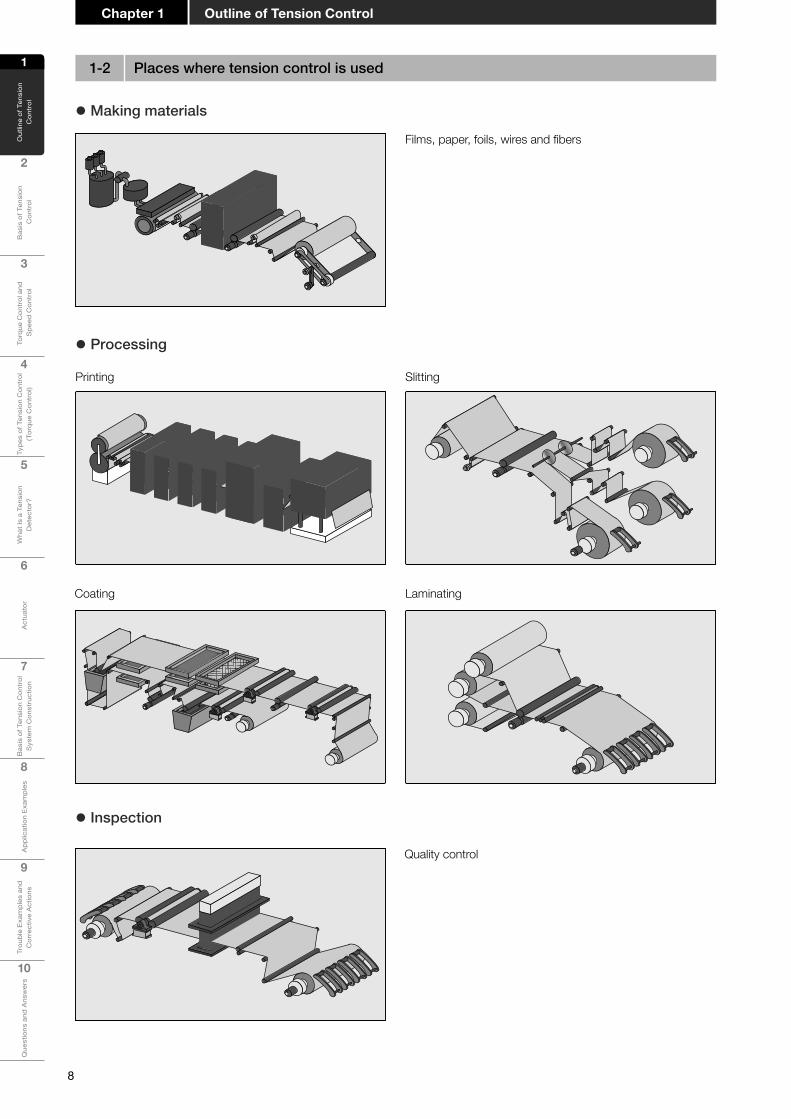
Quality control
z Making materials
Films, paper, foils, wires and fibers
Printing Slitting
Coating Laminating
z Processing
z Inspection
1-2 Places where tension control is used

Chapter 1Outline of Tension Control
9
1
Out
line
of T
ensi
on
Con
trol
2
Bas
is o
f Ten
sion
C
ontr
ol
3
Torq
ue C
ontr
ol a
nd
Spe
ed C
ontr
ol
4
Type
s of
Ten
sion
Con
trol
(T
orqu
e C
ontr
ol)
5
Wha
t Is
a Te
nsio
n D
etec
tor?
6
Act
uato
r
7
Bas
is o
f Ten
sion
Con
trol
S
yste
m C
onst
ruct
ion
8A
pplic
atio
n Ex
ampl
es
9
Trou
ble
Exam
ples
and
C
orre
ctiv
e A
ctio
ns
10
Que
stio
ns a
nd A
nsw
ers
z Plastic shopping bag manufacturing process
Plastic shopping bags (for supermarkets) and garbage bags are manufactured by an inflatable extruder.Heated and melted material such as polyethylene and polypropylene is extruded into a cylindrical shape by blowing air. The extruded cylindrical material is cooled, made flat when the air is discharged from the cavity, shaped into a bag-shaped sheet, and then wound.
z If the tension of the material (paper,film,etc.)islow
If the tension of the material (paper, film, etc.) is low, the material may become slack or form wrinkles during printing.If the tension is too high, the material may shrink after printing.If the tension is unstable, color shift may occur during printing.
1-3 Products to which tension control is applied
Electronic device materialsElectronic device materials Optical filmsOptical films
Paper and plasticPaper and plastic High-tech fibersHigh-tech fibers
Paper Plastic sheets Films Laminated products
Aluminum foils Copper foils Metallic foils Wires
High-techfibersElectronic devices Opticalfilms

10
Outline of Tension Control
1
Out
line
of T
ensi
on
Con
trol
2
Bas
is o
f Ten
sion
Con
trol
3
Torq
ue C
ontr
ol a
nd S
peed
Con
trol
4
Type
s of
Ten
sion
Con
trol
(T
orqu
e C
ontr
ol)
5
Wha
t Is
a Te
nsio
n D
etec
tor?
6
Act
uato
r
7
Bas
is o
f Ten
sion
Con
trol
S
yste
m C
onst
ruct
ion
8
App
licat
ion
Exam
ples
9
Trou
ble
Exam
ples
and
C
orre
ctiv
e A
ctio
ns
10
Que
stio
ns a
nd A
nsw
ers
Chapter 1
2
3
4
5
6
1
Poppingflavor!
Poppingflavor!
DES vapordeposition
Slitting
Laminating
Cross sectional drawing of film
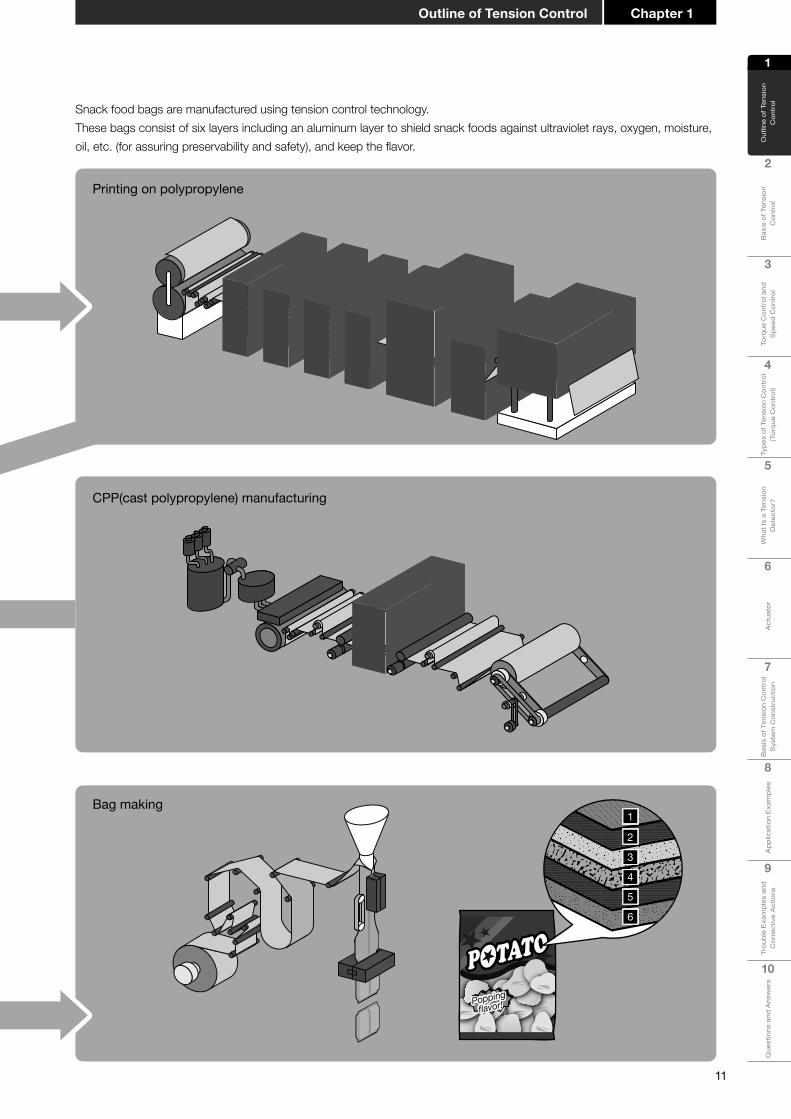
Bag making
CPP(cast polypropylene) manufacturing
234
56
1
DES(biaxially stretched polyethylene)
PolyethyleneCPP(cast polypropylene)
4
56
InkPolyethyleneAluminum
DPP(biaxially stretched polypropylene)
23
1
Printing on polypropyleneDPP (biaxially stretched polypropylene) manufacturingDES (biaxially stretched polyethylene) manufacturing
This section explains various industrial machines which use tension control, while focusing on the snack food bag manufacturing process as an example.
1-4 Tension control in manufacturing process
� 1-4-1 Example: Snack food bag manufacturing process
Chapter 1Outline of Tension Control
11
1
Out
line
of T
ensi
on
Con
trol
2
Bas
is o
f Ten
sion
C
ontr
ol
3
Torq
ue C
ontr
ol a
nd
Spe
ed C
ontr
ol
4
Type
s of
Ten
sion
Con
trol
(T
orqu
e C
ontr
ol)
5
Wha
t Is
a Te
nsio
n D
etec
tor?
6
Act
uato
r
7
Bas
is o
f Ten
sion
Con
trol
S
yste
m C
onst
ruct
ion
8A
pplic
atio
n Ex
ampl
es
9
Trou
ble
Exam
ples
and
C
orre
ctiv
e A
ctio
ns
10
Que
stio
ns a
nd A
nsw
ers
2
3
4
5
6
1
Poppingflavor!
Poppingflavor!
DES vapordeposition
Slitting
Laminating
Cross sectional drawing of film
Bag making
CPP(cast polypropylene) manufacturing
234
56
1
DES(biaxially stretched polyethylene)
PolyethyleneCPP(cast polypropylene)
4
56
InkPolyethyleneAluminum
DPP(biaxially stretched polypropylene)
23
1
Printing on polypropyleneDPP (biaxially stretched polypropylene) manufacturingDES (biaxially stretched polyethylene) manufacturing
Snack food bags are manufactured using tension control technology. These bags consist of six layers including an aluminum layer to shield snack foods against ultraviolet rays, oxygen, moisture, oil, etc. (for assuring preservability and safety), and keep the flavor.

12
Outline of Tension Control
1
Out
line
of T
ensi
on
Con
trol
2
Bas
is o
f Ten
sion
Con
trol
3
Torq
ue C
ontr
ol a
nd S
peed
Con
trol
4
Type
s of
Ten
sion
Con
trol
(T
orqu
e C
ontr
ol)
5
Wha
t Is
a Te
nsio
n D
etec
tor?
6
Act
uato
r
7
Bas
is o
f Ten
sion
Con
trol
S
yste
m C
onst
ruct
ion
8
App
licat
ion
Exam
ples
9
Trou
ble
Exam
ples
and
C
orre
ctiv
e A
ctio
ns
10
Que
stio
ns a
nd A
nsw
ers
Chapter 1
This section introduces an example of a process in which tension control is used in a production line for lithium-ion batteries. � 1-4-2 Example: Lithium-ion battery production line
After the material is machined, it is cut with the slitter to fit in the battery container.
Slitting
Material processing line
The positive and negative electrode materials produced in the material processing line are put in the state where they are insulated by the separator.
Winding
Drying
Winding

Chapter 1Outline of Tension Control
13
1
Out
line
of T
ensi
on
Con
trol
2
Bas
is o
f Ten
sion
C
ontr
ol
3
Torq
ue C
ontr
ol a
nd
Spe
ed C
ontr
ol
4
Type
s of
Ten
sion
Con
trol
(T
orqu
e C
ontr
ol)
5
Wha
t Is
a Te
nsio
n D
etec
tor?
6
Act
uato
r
7
Bas
is o
f Ten
sion
Con
trol
S
yste
m C
onst
ruct
ion
8A
pplic
atio
n Ex
ampl
es
9
Trou
ble
Exam
ples
and
C
orre
ctiv
e A
ctio
ns
10
Que
stio
ns a
nd A
nsw
ers
Products of various sizes can be manufactured by changing the material size and number of turns.
Lithium-ion batteries used for various purposes
Apply slurry (mixture paint) to the positive electrode material (aluminum foil) and the negative electrode material (copper foil).
Coating
Slurry
Electrode material
Cell modularization line
Coating
Laminating
Aging
Capacity measurement
Module assembly
Inspection
Electrolyte injection

14
Outline of Tension Control
1
Out
line
of T
ensi
on
Con
trol
2
Bas
is o
f Ten
sion
Con
trol
3
Torq
ue C
ontr
ol a
nd S
peed
Con
trol
4
Type
s of
Ten
sion
Con
trol
(T
orqu
e C
ontr
ol)
5
Wha
t Is
a Te
nsio
n D
etec
tor?
6
Act
uato
r
7
Bas
is o
f Ten
sion
Con
trol
S
yste
m C
onst
ruct
ion
8
App
licat
ion
Exam
ples
9
Trou
ble
Exam
ples
and
C
orre
ctiv
e A
ctio
ns
10
Que
stio
ns a
nd A
nsw
ers
Chapter 1
Main wing front edge
Horizontal tail
Vertical tail
z For example:Carbon fiber is attractive for improving fuel efficiency, improving cruising range and reducing carbon dioxide emissions. Tension control technology is also used in the production of carbon fiber and for processing molded products containing carbon fiber.
Aircraft
z For example:For the same purpose as with aircraft, tension control technology is used in processing molded products containing carbon fiber.
Automobile parts
Door reinforcing material
Engine hood
Lithium-ion battery
Ceiling
1-5 Let's look for tension control around you

Chapter 1Outline of Tension Control
15
1
Out
line
of T
ensi
on
Con
trol
2
Bas
is o
f Ten
sion
C
ontr
ol
3
Torq
ue C
ontr
ol a
nd
Spe
ed C
ontr
ol
4
Type
s of
Ten
sion
Con
trol
(T
orqu
e C
ontr
ol)
5
Wha
t Is
a Te
nsio
n D
etec
tor?
6
Act
uato
r
7
Bas
is o
f Ten
sion
Con
trol
S
yste
m C
onst
ruct
ion
8A
pplic
atio
n Ex
ampl
es
9
Trou
ble
Exam
ples
and
C
orre
ctiv
e A
ctio
ns
10
Que
stio
ns a
nd A
nsw
ers
z For example:In liquid crystal televisions, tension control technology is used in high-function sheets for liquid crystal, film capacitors and others.
Polarizing plates and protective materials
z For example:Electronic circuits are built into mobile phones, and are mounted on printed-circuit boards.Tension control technology is also used to manufacture cubic components of 1 to 2 mm called ceramic capacitors, a type of electronic component.
Ceramic capacitors
FoilFilm
z For example:Batteries such as for mobile phones are made by laminating thin metal foils such as aluminum. Advanced tension control is required to evenly laminate thin metal foils.
Lithium-ion battery

16
Outline of Tension Control
1
Out
line
of T
ensi
on
Con
trol
2
Bas
is o
f Ten
sion
Con
trol
3
Torq
ue C
ontr
ol a
nd S
peed
Con
trol
4
Type
s of
Ten
sion
Con
trol
(T
orqu
e C
ontr
ol)
5
Wha
t Is
a Te
nsio
n D
etec
tor?
6
Act
uato
r
7
Bas
is o
f Ten
sion
Con
trol
S
yste
m C
onst
ruct
ion
8
App
licat
ion
Exam
ples
9
Trou
ble
Exam
ples
and
C
orre
ctiv
e A
ctio
ns
10
Que
stio
ns a
nd A
nsw
ers
Chapter 1
z If tension control is not used
1-6 Effectofintroducingtensioncontrol
What happens when winding without tension control? Imagine the shape of a roll of toilet paper unwound and then rewound by hand, or the shape of a fishing reel wound without a weight.The shape will not be wound neatly!
� 1-6-1 Improving the wound shapeIn the material processing and winding stages, satisfactory wound shape can be achieved by tension control.If tension control is not performed properly, the following problems may occur:
• Chrysanthemum pattern: The center is crushed due to tight winding.
• Dented roll: The center is dented after winding.
• Arc-shaped curve and bamboo shoot: The material slips out of place during winding.
• Shoulder-missing roll: Both sides are missed during winding.
Chrysanthemum pattern Dented roll
Arc-shaped curve bamboo shoot Shoulder-missing roll
Chapter 1Outline of Tension Control
17
1
Out
line
of T
ensi
on
Con
trol
2
Bas
is o
f Ten
sion
C
ontr
ol
3
Torq
ue C
ontr
ol a
nd
Spe
ed C
ontr
ol
4
Type
s of
Ten
sion
Con
trol
(T
orqu
e C
ontr
ol)
5
Wha
t Is
a Te
nsio
n D
etec
tor?
6
Act
uato
r
7
Bas
is o
f Ten
sion
Con
trol
S
yste
m C
onst
ruct
ion
8A
pplic
atio
n Ex
ampl
es
9
Trou
ble
Exam
ples
and
C
orre
ctiv
e A
ctio
ns
10
Que
stio
ns a
nd A
nsw
ers
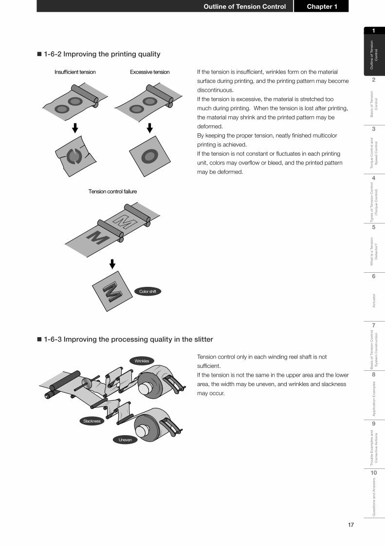
� 1-6-2 Improving the printing quality
Excessive tensionInsufficient tension If the tension is insufficient, wrinkles form on the material surface during printing, and the printing pattern may become discontinuous.If the tension is excessive, the material is stretched too much during printing. When the tension is lost after printing, the material may shrink and the printed pattern may be deformed.By keeping the proper tension, neatly finished multicolor printing is achieved.If the tension is not constant or fluctuates in each printing unit, colors may overflow or bleed, and the printed pattern may be deformed.
Tension control failure
Color shift
M
� 1-6-3 Improving the processing quality in the slitter
Wrinkles
Slackness
Uneven
Tension control only in each winding reel shaft is not sufficient.If the tension is not the same in the upper area and the lower area, the width may be uneven, and wrinkles and slackness may occur.
18
Outline of Tension Control
1
Out
line
of T
ensi
on
Con
trol
2
Bas
is o
f Ten
sion
Con
trol
3
Torq
ue C
ontr
ol a
nd S
peed
Con
trol
4
Type
s of
Ten
sion
Con
trol
(T
orqu
e C
ontr
ol)
5
Wha
t Is
a Te
nsio
n D
etec
tor?
6
Act
uato
r
7
Bas
is o
f Ten
sion
Con
trol
S
yste
m C
onst
ruct
ion
8
App
licat
ion
Exam
ples
9
Trou
ble
Exam
ples
and
C
orre
ctiv
e A
ctio
ns
10
Que
stio
ns a
nd A
nsw
ers
Chapter 1
Point! Why is tension control required?
The purpose of tension control varies depending on the material and machine.When the tension is controlled properly, the material can be transferred to the next process (such as printing, laminating and machining) with proper tension, which stabilizes the material travel, ensures dimensional accuracy and achieves satisfactory winding.
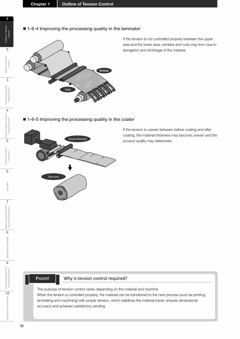
� 1-6-4 Improving the processing quality in the laminator
Curls
Wrinkles
If the tension is not controlled properly between the upper area and the lower area, wrinkles and curls may form due to elongation and shrinkage of the material.
� 1-6-5 Improving the processing quality in the coater
Uneven thickness
Not round
If the tension is uneven between before coating and after coating, the material thickness may become uneven and the product quality may deteriorate.
Chapter 2
Basis of Tension Control
2-1 What is tension?2-2 What is torque?2-3 Forces causing tension

20
1
Out
line
of T
ensi
on
Con
trol
2
Bas
is o
f Ten
sion
Con
trol
3
Torq
ue C
ontr
ol a
nd S
peed
Con
trol
4
Type
s of
Ten
sion
Con
trol
(T
orqu
e C
ontr
ol)
5
Wha
t Is
a Te
nsio
n D
etec
tor?
6
Act
uato
r
7
Bas
is o
f Ten
sion
Con
trol
S
yste
m C
onst
ruct
ion
8
App
licat
ion
Exam
ples
9
Trou
ble
Exam
ples
and
C
orre
ctiv
e A
ctio
ns
10
Que
stio
ns a
nd A
nsw
ers
Basis of Tension ControlChapter 2
Basis of Tension Control2Chapter
When two people pull a rope against each other, tension is applied to the rope.Clearly, the pulling force (F ) and the pulled force (F ) balance each other and the same tension is applied by both people while the rope is stopped.
What is the tension when the rope is moving?If one side is not fixed, the rope moves to the right. A smaller force ( f ) acts on the rope.This means that the tension is not determined by the force on the pulling side when the rope is moving. The tension is affected by the force on the pulled side.
FF
ff
z Pulling force and pulled force
Various physical phenomena occur in machines which process long materials.However, it is difficult to link them with phenomena which occur in daily life.
2-1 What is tension?
21
1
Out
line
of T
ensi
on
Con
trol
2
Bas
is o
f Ten
sion
Con
trol
3
Torq
ue C
ontr
ol a
nd S
peed
Con
trol
4
Type
s of
Ten
sion
Con
trol
(T
orqu
e C
ontr
ol)
5
Wha
t Is
a Te
nsio
n D
etec
tor?
6
Act
uato
r
7
Bas
is o
f Ten
sion
Con
trol
S
yste
m C
onst
ruct
ion
8A
pplic
atio
n Ex
ampl
es
9
Trou
ble
Exam
ples
and
C
orre
ctiv
e A
ctio
ns
10
Que
stio
ns a
nd A
nsw
ers
Chapter 2Basis of Tension Control
Outsidediameter( D )
Feed motorFeed motorFeed motor
Motor torqueMotor torqueMotor torque
Braking torqueBraking torqueBraking torqueRadius ( D/2 )Radius ( D/2 )Radius ( D/2 )
Torque (T )
Tension ( f )
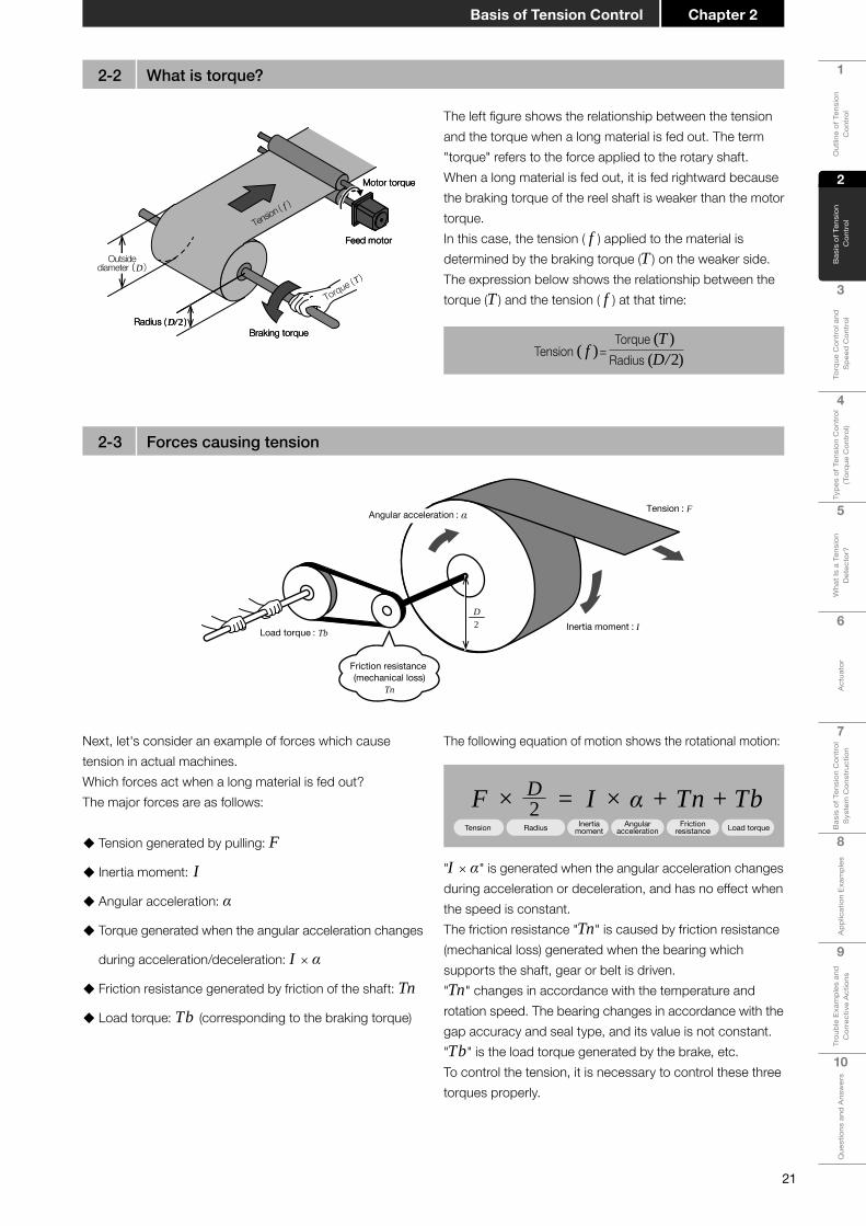
The left figure shows the relationship between the tension and the torque when a long material is fed out. The term "torque" refers to the force applied to the rotary shaft.When a long material is fed out, it is fed rightward because the braking torque of the reel shaft is weaker than the motor torque.In this case, the tension ( f ) applied to the material is determined by the braking torque (T ) on the weaker side.The expression below shows the relationship between the torque (T ) and the tension ( f ) at that time:
Tension ( f )=Torque (T )
Radius (D/2)
2-2 What is torque?
2-3 Forces causing tension
Tension : F
Inertia moment : I
Angular acceleration : α
Load torque : Tb
Friction resistance (mechanical loss)
Tn
D2
F × = I × α + Tn + TbTension Radius Inertia
momentAngular
accelerationFriction
resistance Load torque
D2
The following equation of motion shows the rotational motion:
"I × α" is generated when the angular acceleration changes during acceleration or deceleration, and has no effect when the speed is constant.The friction resistance "Tn" is caused by friction resistance (mechanical loss) generated when the bearing which supports the shaft, gear or belt is driven."Tn" changes in accordance with the temperature and rotation speed. The bearing changes in accordance with the gap accuracy and seal type, and its value is not constant."Tb" is the load torque generated by the brake, etc.To control the tension, it is necessary to control these three torques properly.
Next, let's consider an example of forces which cause tension in actual machines.Which forces act when a long material is fed out?The major forces are as follows:
� Tension generated by pulling: F
� Inertia moment: I
� Angular acceleration: α
� Torque generated when the angular acceleration changes
during acceleration/deceleration: I × α
� Friction resistance generated by friction of the shaft: Tn
� Load torque: Tb (corresponding to the braking torque)

22
1
Out
line
of T
ensi
on
Con
trol
2
Bas
is o
f Ten
sion
Con
trol
3
Torq
ue C
ontr
ol a
nd S
peed
Con
trol
4
Type
s of
Ten
sion
Con
trol
(T
orqu
e C
ontr
ol)
5
Wha
t Is
a Te
nsio
n D
etec
tor?
6
Act
uato
r
7
Bas
is o
f Ten
sion
Con
trol
S
yste
m C
onst
ruct
ion
8
App
licat
ion
Exam
ples
9
Trou
ble
Exam
ples
and
C
orre
ctiv
e A
ctio
ns
10
Que
stio
ns a
nd A
nsw
ers
Basis of Tension ControlChapter 2
� 2-3-1 Inertia moment
The inertia moment is an index which expresses the difficulty of rotating in the rotating body.The mass in linear motion indicates the "difficulty of moving" and "difficulty of stopping" when a force is applied.The inertia moment in rotational motion indicates the "difficulty of rotating" and "difficulty of stopping" when a force to cause rotation is applied.For example, it is difficult to start rotating a reel shaft that has a large outside diameter or large mass, but the shaft inherently continues to rotate once it starts rotating. This property is referred to as "The inertia moment is large".The expression below shows the property:
Inertia moment = Σ[(Distance from center of rotation) × (Mass)]
The inertia moment is large.
The inertia moment is small.
Decelerated
Constant speed
Accelerated
It is necessary to consider the inertia when accelerating or decelerating a rotating body. The torque "T" required for accelerating a rotating body whose inertia is "I" is as follows:
Accordingly, it is necessary to consider that the torque appears as tension on the + side (pulling side) when accelerating the rotating body by pulling it, and appears as tension on the - side (slacking side) when decelerating the rotating body.Torque is not generated during steady operation at a constant speed because the angular acceleration " α " is 0.
T = I × α

23
1
Out
line
of T
ensi
on
Con
trol
2
Bas
is o
f Ten
sion
Con
trol
3
Torq
ue C
ontr
ol a
nd S
peed
Con
trol
4
Type
s of
Ten
sion
Con
trol
(T
orqu
e C
ontr
ol)
5
Wha
t Is
a Te
nsio
n D
etec
tor?
6
Act
uato
r
7
Bas
is o
f Ten
sion
Con
trol
S
yste
m C
onst
ruct
ion
8A
pplic
atio
n Ex
ampl
es
9
Trou
ble
Exam
ples
and
C
orre
ctiv
e A
ctio
ns
10
Que
stio
ns a
nd A
nsw
ers
Chapter 2Basis of Tension Control
Point! Let's study the basic concepts of tension, torque, inertia moment and friction resistance (mechanical loss)!
� 2-3-2 Force generated by the friction resistance (mechanical loss)
Gear Bearing
When the shaft rotates, friction resistance is generated in the bearing which supports the shaft, gear, pulley, etc.The friction resistance also causes tension.Because the effect of the friction resistance cannot be ignored when controlling low tension, proper measures are required.

24
1
Out
line
of T
ensi
on
Con
trol
2
Bas
is o
f Ten
sion
Con
trol
3
Torq
ue C
ontr
ol a
nd S
peed
Con
trol
4
Type
s of
Ten
sion
Con
trol
(T
orqu
e C
ontr
ol)
5
Wha
t Is
a Te
nsio
n D
etec
tor?
6
Act
uato
r
7
Bas
is o
f Ten
sion
Con
trol
S
yste
m C
onst
ruct
ion
8
App
licat
ion
Exam
ples
9
Trou
ble
Exam
ples
and
C
orre
ctiv
e A
ctio
ns
10
Que
stio
ns a
nd A
nsw
ers
Basis of Tension ControlChapter 2
MEMO

Chapter 3
Torque Control and Speed Control
3-1 Torque control and speed control3-2 How to use torque control and speed control
properly3-3 Examples of speed control3-4 Systemdesignflow

26
1
Out
line
of T
ensi
on
Con
trol
2
Bas
is o
f Ten
sion
C
ontr
ol
3
Torq
ue C
ontr
ol a
nd
Spe
ed C
ontr
ol
4
Type
s of
Ten
sion
Con
trol
(T
orqu
e C
ontr
ol)
5
Wha
t Is
a Te
nsio
n D
etec
tor?
6
Act
uato
r
7
Bas
is o
f Ten
sion
Con
trol
S
yste
m C
onst
ruct
ion
8
App
licat
ion
Exam
ples
9
Trou
ble
Exam
ples
and
C
orre
ctiv
e A
ctio
ns
10
Que
stio
ns a
nd A
nsw
ers
Torque Control and Speed ControlChapter 3
Torque control
Brake
Feed roll
Feed motor
Powder brake
Speed control
Feed roll
The material speed is detected.
Feed motor
Vector control motor
Dancer rollMoves
Synchronizes
Torque Control and Speed ControlChapter
33-1 Torque control and speed control
In torque control, only the torque required to control the tension is controlled among the three torques acting on a long material described in Section 2.3; the other torques required to control the friction resistance and inertia are controlled and corrected as necessary.
There are two main methods of tension control, the method using torque control and the method using speed control.
In speed control, the speed of feeding a material is controlled to stabilize the tension.The tension is applied through pressurization by the weight and dancer roll, and is determined by the course of events. Accordingly, in order to manipulate only the torque for controlling the tension during speed control, it is necessary to change the pressurization of the dancer roll or to perform draw control which utilizes the difference in the material feed speed.

27
1
Out
line
of T
ensi
on
Con
trol
2
Bas
is o
f Ten
sion
C
ontr
ol
3
Torq
ue C
ontr
ol a
nd
Spe
ed C
ontr
ol
4
Type
s of
Ten
sion
Con
trol
(T
orqu
e C
ontr
ol)
5
Wha
t Is
a Te
nsio
n D
etec
tor?
6
Act
uato
r
7
Bas
is o
f Ten
sion
Con
trol
S
yste
m C
onst
ruct
ion
8A
pplic
atio
n Ex
ampl
es
9
Trou
ble
Exam
ples
and
C
orre
ctiv
e A
ctio
ns
10
Que
stio
ns a
nd A
nsw
ers
Chapter 3Torque Control and Speed Control
Powder clutch
ZKB-BN
Powder brake
ZKB-XN
AC servo motor
MELSERVO-J4
Inverter(for vector control)
FR-A800
* An actuator is: Driving equipment such as clutches, brakes and motors installed in the winding reel shaft and unwinding reel shaft.
Control is difficult when the inertia is large!
Feed roll
Feed motor
Powder brake
On the other hand, if the effect of the inertia (inertia moment) during acceleration/deceleration and the mechanical friction change considerably during torque control, it is difficult to completely eliminate fluctuations of the tension caused by such changes.As the reel diameter becomes larger, the inertia of the reel becomes larger accordingly, and the torque required to compensate the inertia increases.Accordingly, torque control becomes more difficult with larger inertia and higher acceleration/deceleration speed.
The left figure shows an example of torque control during unwinding. In torque control, the effect of inertia caused by acceleration/deceleration and the friction resistance are almost constant when the material moving speed is constant. Accordingly, the tension can be controlled easily only by applying a constant braking torque.The rotation speed of the reel shaft is determined by the course of events based on the feed speed and reel diameter (material diameter wound around the reel shaft). By adopting an actuator* which generates a constant torque even if the rotation speed changes, the intended tension can be achieved easily without considering changes in the rotation speed of the reel shaft only by changing the torque for controlling the tension.
� 3-1-1 Mechanism of torque control
Applicable equipment
Vector control motor
SF-V5RU

28
1
Out
line
of T
ensi
on
Con
trol
2
Bas
is o
f Ten
sion
C
ontr
ol
3
Torq
ue C
ontr
ol a
nd
Spe
ed C
ontr
ol
4
Type
s of
Ten
sion
Con
trol
(T
orqu
e C
ontr
ol)
5
Wha
t Is
a Te
nsio
n D
etec
tor?
6
Act
uato
r
7
Bas
is o
f Ten
sion
Con
trol
S
yste
m C
onst
ruct
ion
8
App
licat
ion
Exam
ples
9
Trou
ble
Exam
ples
and
C
orre
ctiv
e A
ctio
ns
10
Que
stio
ns a
nd A
nsw
ers
Torque Control and Speed ControlChapter 3
� 3-1-2 Mechanism of speed control
Feed roll
The material speed is detected.
Feed motor
Vector control motor
Dancer roll
Moves
Synchronizes
It is difficult to follow motions.
The inertia increases.
The left figure shows an example of speed control during unwinding.In actual machines, the rotation speed of the motor which feeds out the material is controlled.For applying the tension, the weight is hung on the dancer roll* as shown in the left figure or the dancer roll is pressurized by the air cylinder, etc.
* A dancer roll is: A follower roll (guide roll) whose spindle can move longitudinally or laterally. The tension of the material is determined by the load applied to the dancer roll spindle.
In speed control, the speed of the material moving in the machine is detected, and the machine is controlled so that other driving parts of the machine synchronize with the detected speed. Accordingly, it is easy to stabilize the movement of the material.In addition, because the torque is determined by the course of events even if the torque caused by inertia and the torque caused by mechanical friction fluctuate, the stability of the material deteriorates less.However, because it is not possible to change only the torque for controlling the tension, the tension accuracy is low. In speed control using a dancer roll, the tension is changed by the weight attached to the dancer roll or the pressurization applied to the dancer roll by the air cylinder, etc. If a weight is attached, the inertia of the dancer roll increases. As a result, the response of speed detection becomes low, and the tension may fluctuate in some cases. If the dancer roll is pressurized by the air cylinder, etc., fluctuations in the air cause fluctuations in the tension.Accordingly, the absolute control accuracy of the tension is lower than that in torque control.

29
1
Out
line
of T
ensi
on
Con
trol
2
Bas
is o
f Ten
sion
C
ontr
ol
3
Torq
ue C
ontr
ol a
nd
Spe
ed C
ontr
ol
4
Type
s of
Ten
sion
Con
trol
(T
orqu
e C
ontr
ol)
5
Wha
t Is
a Te
nsio
n D
etec
tor?
6
Act
uato
r
7
Bas
is o
f Ten
sion
Con
trol
S
yste
m C
onst
ruct
ion
8A
pplic
atio
n Ex
ampl
es
9
Trou
ble
Exam
ples
and
C
orre
ctiv
e A
ctio
ns
10
Que
stio
ns a
nd A
nsw
ers
Chapter 3Torque Control and Speed Control
Applicable equipment
AC servo motor
MELSERVO-J4Inverter
(for vector control)
FR-A800
Vector control motor
SF-V5RU
� Dancer roll
z Weight dancer roll
z Spring dancer roll
Dancer rolls are rollers which move considerably longitudinally or laterally, and are classified into weight dancer rolls, spring dancer rolls, etc.
Motor
Motor
Weight
• The tension is 1/2 of the mass of the weight.
• The dancer roll position is not related to the tension.
• The dancer roll position depends on the difference between the input speed and the output speed.
• The material is easily made stable even during acceleration or deceleration.
• Synchronization is achieved easily even if the material between the driving controlled shafts is long.
• It is necessary to change the mass of the weight in order to change the tension.
• The spring force of the spring causes the tension.
• The dancer roll position is changed by the tension.
• The dancer roll position is not changed by the difference in speed.
• The tension control accuracy is better compared with the weight dancer roll.
• The dancer roll absorbs shock.
• It is necessary to stabilize the spring (so a damper is required).Vector control motor
Motor
Spring
Damper
30
1
Out
line
of T
ensi
on
Con
trol
2
Bas
is o
f Ten
sion
C
ontr
ol
3
Torq
ue C
ontr
ol a
nd
Spe
ed C
ontr
ol
4
Type
s of
Ten
sion
Con
trol
(T
orqu
e C
ontr
ol)
5
Wha
t Is
a Te
nsio
n D
etec
tor?
6
Act
uato
r
7
Bas
is o
f Ten
sion
Con
trol
S
yste
m C
onst
ruct
ion
8
App
licat
ion
Exam
ples
9
Trou
ble
Exam
ples
and
C
orre
ctiv
e A
ctio
ns
10
Que
stio
ns a
nd A
nsw
ers
Torque Control and Speed ControlChapter 3
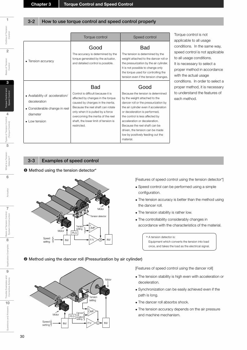
u Method using the tension detector*
v Method using the dancer roll (Pressurization by air cylinder)
• The tension stability is high even with acceleration or deceleration.
• Synchronization can be easily achieved even if the path is long.
• The dancer roll absorbs shock.
• The tension accuracy depends on the air pressure and machine mechanism.
[Features of speed control using the dancer roll]
Motor
Motor
Speedsetting
Tensionsetting
INV F/V
Dancer rollpositionsetting
INV+
PLG
+CMP−
Motor
Motor
Speedsetting INV
+CMP−
F/V
Tensionsetting
INV+
PLG
Tension detector
• Speed control can be performed using a simple configuration.
• The tension accuracy is better than the method using the dancer roll.
• The tension stability is rather low.
• The controllability considerably changes in accordance with the characteristics of the material.
[Features of speed control using the tension detector*]
* A tension detector is: Equipment which converts the tension into load once, and takes the load as the electrical signal.
Torque control is not applicable to all usage conditions. In the same way, speed control is not applicable to all usage conditions.It is necessary to select a proper method in accordance with the actual usage conditions. In order to select a proper method, it is necessary to understand the features of each method.
Torque control Speed control
• Tension accuracy
Good BadThe accuracy is determined by the torque generated by the actuator, and detailed control is possible.
The tension is determined by the weight attached to the dancer roll or the pressurization by the air cylinder. It is not possible to change only the torque used for controlling the tension even if the tension changes.
• Availability of acceleration/deceleration
• Considerable change in reel diameter
• Low tension
Bad GoodControl is difficult because it is affected by changes in the torque caused by changes in the inertia.Because the reel shaft can rotate only when it is pulled by a force overcoming the inertia of the reel shaft, the lower limit of tension is restricted.
Because the tension is determined by the weight attached to the dancer roll or the pressurization by the air cylinder even if acceleration or deceleration is performed, the control is less affected by acceleration or deceleration.Because the reel shaft can be driven, the tension can be made low by positively feeding out the material.
3-2 How to use torque control and speed control properly
3-3 Examples of speed control

31
1
Out
line
of T
ensi
on
Con
trol
2
Bas
is o
f Ten
sion
C
ontr
ol
3
Torq
ue C
ontr
ol a
nd
Spe
ed C
ontr
ol
4
Type
s of
Ten
sion
Con
trol
(T
orqu
e C
ontr
ol)
5
Wha
t Is
a Te
nsio
n D
etec
tor?
6
Act
uato
r
7
Bas
is o
f Ten
sion
Con
trol
S
yste
m C
onst
ruct
ion
8A
pplic
atio
n Ex
ampl
es
9
Trou
ble
Exam
ples
and
C
orre
ctiv
e A
ctio
ns
10
Que
stio
ns a
nd A
nsw
ers
Chapter 3Torque Control and Speed Control
w Method using the dancer roll (Pressurization by powder clutch)
When many follower rolls are driven by the traveling material as shown in the left figure, the tension may become excessive toward the head area due to the effect of mechanical loss in the follower rolls.For driving each follower roll to prevent excessive tension, it is necessary to control the speed in accordance with the elongation and shrinkage of the material.
x Method using draw control
• The tension can be changed by the torque of the powder clutch.
• The dancer roll position depends on the difference between the input speed and the output speed.
• Synchronization can be easily achieved even if the path is long.
• The dancer roll position is not related to the tension.
[Features of speed control using the powder clutch]
It is possible to drive each roll using the servo motors, and to drive the servo motors in the rear area at a higher speed than the servo motors in the front area using the ratio setting units as shown in the left figure.The elongation percentage is approximately 0.1 to 5%.
The method of driving rolls in the rear area at a higher speed in this way is called draw control. The operation tension is determined by the elongation percentage property of the material.
Motor
Motor Tensionsetting
+CMP−
AMP
F/V
Speedsetting INV
INV+PLG
Dancer rollpositionsetting
Counterweight
Follower roll
Feed roll
Excessivetension
Feed motor
Ratio setting unit
Feed roll
Feed motor
Servo motor
Applicable equipment
AC servo motor
MELSERVO-J4Inverter
FR-A800
Stationary tension detector
LX-TD
Flange-type tension detector
LX7-F

32
1
Out
line
of T
ensi
on
Con
trol
2
Bas
is o
f Ten
sion
C
ontr
ol
3
Torq
ue C
ontr
ol a
nd
Spe
ed C
ontr
ol
4
Type
s of
Ten
sion
Con
trol
(T
orqu
e C
ontr
ol)
5
Wha
t Is
a Te
nsio
n D
etec
tor?
6
Act
uato
r
7
Bas
is o
f Ten
sion
Con
trol
S
yste
m C
onst
ruct
ion
8
App
licat
ion
Exam
ples
9
Trou
ble
Exam
ples
and
C
orre
ctiv
e A
ctio
ns
10
Que
stio
ns a
nd A
nsw
ers
Torque Control and Speed ControlChapter 3
[1] Confirming the required specifications of the machine
[2] Determining the specifications of the machine
[3] Dividing processes in the tension control system
[4] Determining the main shaft
[5] Determining the control method between driving shafts
[6] Determining the actuator method
[7] Selecting the actuator
[8] Evaluating the actuator
[9] Determining the control unit
[10] Confirming the control unit
Properties of web, processing processespurpose of machine, etc.
Line speed, tension, reel diameter, roll diameter, etc.
Tension cutting position, control main body (control method), etc.
Determination of driving shaft regarded as main shaft
Reexamining the machinespecifications
Selection between torque control and speed control
Selection of actuator to be used
Selection of actuator capacity (model)
Is proper actuator selected?
Selection of control unit based on control method
Is proper control unit selected?
Completed
Construction of tension control system
Reexamining the controlmethod
YES
YES
NO
NO
Point! Let's consider the combination of control type (torque control or speed control) and auxiliary device (dancer roll or tension detector).
3-4 Systemdesignflow

Chapter 4
Types of Tension Control (Torque Control)
4-1 Manual control4-2 Open-loop control4-3 Closed-loop control
34
1
Out
line
of T
ensi
on
Con
trol
2
Bas
is o
f Ten
sion
C
ontr
ol
3
Torq
ue C
ontr
ol a
nd
Spe
ed C
ontr
ol
4
Type
s of
Ten
sion
Con
trol
(T
orqu
e C
ontr
ol)
5
Wha
t Is
a Te
nsio
n D
etec
tor?
6
Act
uato
r
7
Bas
is o
f Ten
sion
Con
trol
S
yste
m C
onst
ruct
ion
8
App
licat
ion
Exam
ples
9
Trou
ble
Exam
ples
and
C
orre
ctiv
e A
ctio
ns
10
Que
stio
ns a
nd A
nsw
ers
Types of Tension Control (Torque Control)Chapter 4
Types of Tension Control(Torque Control)
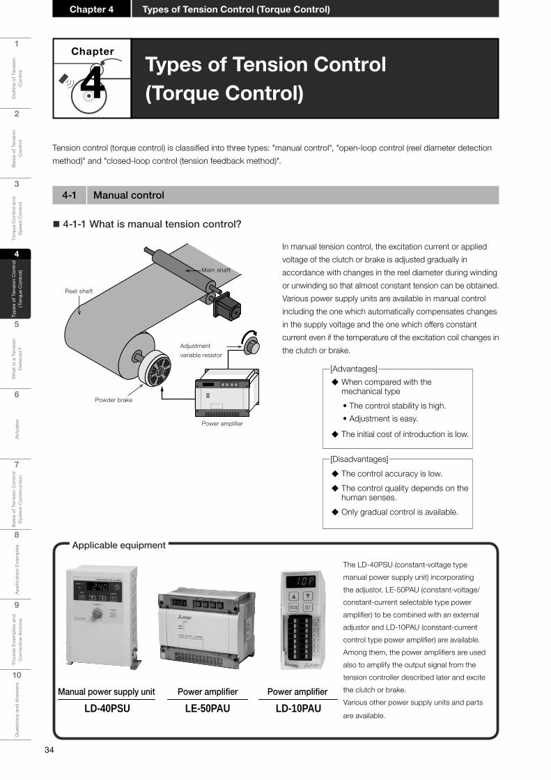
Tension control (torque control) is classified into three types: "manual control", "open-loop control (reel diameter detection method)" and "closed-loop control (tension feedback method)".
� 4-1-1 What is manual tension control?
Chapter
4
The LD-40PSU (constant-voltage type manual power supply unit) incorporating the adjustor, LE-50PAU (constant-voltage/constant-current selectable type power amplifier) to be combined with an external adjustor and LD-10PAU (constant-current control type power amplifier) are available.Among them, the power amplifiers are used also to amplify the output signal from the tension controller described later and excite the clutch or brake.Various other power supply units and parts
are available.
In manual tension control, the excitation current or applied voltage of the clutch or brake is adjusted gradually in accordance with changes in the reel diameter during winding or unwinding so that almost constant tension can be obtained.Various power supply units are available in manual control including the one which automatically compensates changes in the supply voltage and the one which offers constant current even if the temperature of the excitation coil changes in the clutch or brake.
Main shaft
Power amplifier
Adjustment variable resistor
Powder brake
Reel shaft
� The control accuracy is low. � The control quality depends on the human senses. � Only gradual control is available.
� When compared with the mechanical type • The control stability is high.• Adjustment is easy.
� The initial cost of introduction is low.
Manual power supply unit
LD-40PSUPoweramplifier
LE-50PAUPoweramplifier
LD-10PAU
Applicable equipment
4-1 Manual control
[Advantages]
[Disadvantages]

35
1
Out
line
of T
ensi
on
Con
trol
2
Bas
is o
f Ten
sion
C
ontr
ol
3
Torq
ue C
ontr
ol a
nd
Spe
ed C
ontr
ol
4
Type
s of
Ten
sion
Con
trol
(T
orqu
e C
ontr
ol)
5
Wha
t Is
a Te
nsio
n D
etec
tor?
6
Act
uato
r
7
Bas
is o
f Ten
sion
Con
trol
S
yste
m C
onst
ruct
ion
8A
pplic
atio
n Ex
ampl
es
9
Trou
ble
Exam
ples
and
C
orre
ctiv
e A
ctio
ns
10
Que
stio
ns a
nd A
nsw
ers
Chapter 4Types of Tension Control (Torque Control)
� 4-1-2 Usage example of manual power supply unit
When the reel diameter ratio (Maximum diameter/Minimum diameter) is small in the processing machine for paper, film, wire, etc., for the intermediate shaft whose reel diameter does not change, or when high tension accuracy is not required, the manual power supply unit is used as shown in the left figure.Though high tension accuracy is not expected, the tension can be changed easily using the variable resistor provided on the panel of the power supply unit. In addition, because the structure is simple, the tension can be adjusted at low cost.
Manual power supply unit
Powder brake
� 4-1-3Usageexampleofpoweramplifier
When there are many controlled shafts and the PLC performs centralized control, it is recommended to use the power amplifier as shown in the left figure so that the powder brake/clutch can be used very easily.
Power ampli�er
Proximity switch
Power ampli�er
PLC
36
1
Out
line
of T
ensi
on
Con
trol
2
Bas
is o
f Ten
sion
C
ontr
ol
3
Torq
ue C
ontr
ol a
nd
Spe
ed C
ontr
ol
4
Type
s of
Ten
sion
Con
trol
(T
orqu
e C
ontr
ol)
5
Wha
t Is
a Te
nsio
n D
etec
tor?
6
Act
uato
r
7
Bas
is o
f Ten
sion
Con
trol
S
yste
m C
onst
ruct
ion
8
App
licat
ion
Exam
ples
9
Trou
ble
Exam
ples
and
C
orre
ctiv
e A
ctio
ns
10
Que
stio
ns a
nd A
nsw
ers
Types of Tension Control (Torque Control)Chapter 4
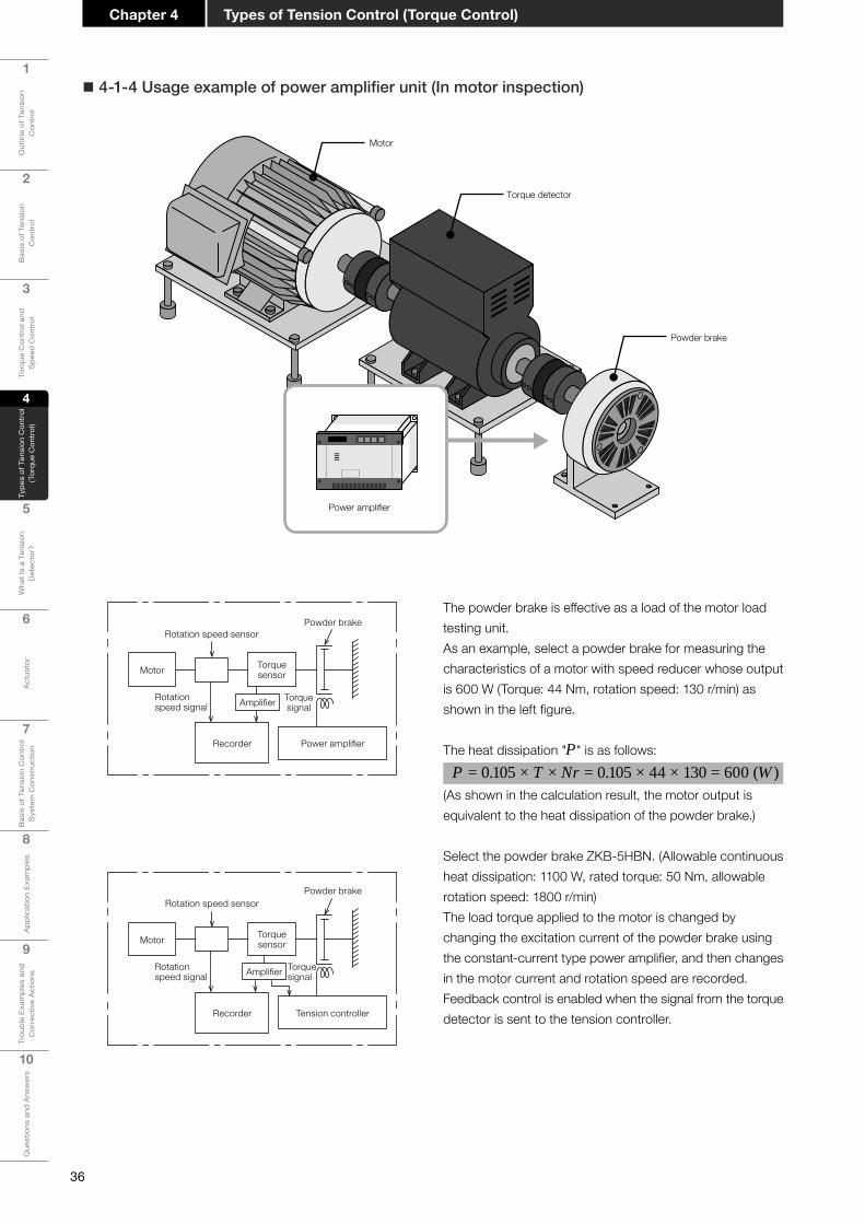
� 4-1-4Usageexampleofpoweramplifierunit(Inmotorinspection)
Motor
Powder brake
Power amplifier
Torque detector
The powder brake is effective as a load of the motor load testing unit.As an example, select a powder brake for measuring the characteristics of a motor with speed reducer whose output is 600 W (Torque: 44 Nm, rotation speed: 130 r/min) as shown in the left figure.
The heat dissipation "P" is as follows: P = 0.105 × T × Nr = 0.105 × 44 × 130 = 600 (W )
(As shown in the calculation result, the motor output is equivalent to the heat dissipation of the powder brake.)
Select the powder brake ZKB-5HBN. (Allowable continuous heat dissipation: 1100 W, rated torque: 50 Nm, allowable rotation speed: 1800 r/min)The load torque applied to the motor is changed by changing the excitation current of the powder brake using the constant-current type power amplifier, and then changes in the motor current and rotation speed are recorded.Feedback control is enabled when the signal from the torque detector is sent to the tension controller.
Rotation speed sensorPowder brake
Motor Torquesensor
Recorder
Torquesignal
Rotationspeed signal Amplifier
Power amplifier
Rotation speed sensorPowder brake
Motor Torquesensor
Recorder
Torquesignal
Rotationspeed signal
Tension controller
Amplifier
37
1
Out
line
of T
ensi
on
Con
trol
2
Bas
is o
f Ten
sion
C
ontr
ol
3
Torq
ue C
ontr
ol a
nd
Spe
ed C
ontr
ol
4
Type
s of
Ten
sion
Con
trol
(T
orqu
e C
ontr
ol)
5
Wha
t Is
a Te
nsio
n D
etec
tor?
6
Act
uato
r
7
Bas
is o
f Ten
sion
Con
trol
S
yste
m C
onst
ruct
ion
8A
pplic
atio
n Ex
ampl
es
9
Trou
ble
Exam
ples
and
C
orre
ctiv
e A
ctio
ns
10
Que
stio
ns a
nd A
nsw
ers
Chapter 4Types of Tension Control (Torque Control)
4-2 Open-loop control
� 4-2-1 What is open-loop control?
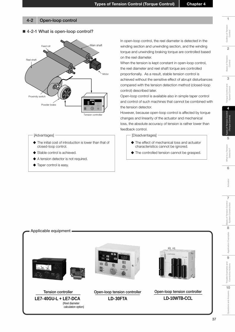
� The initial cost of introduction is lower than that of closed-loop control.
� Stable control is achieved. � A tension detector is not required. � Taper control is easy.
� The effect of mechanical loss and actuator characteristics cannot be ignored. � The controlled tension cannot be grasped.
Tension controller
Proximity switch
Powder brake
Motor
Main shaft
Reel shaft
Feed roll
In open-loop control, the reel diameter is detected in the winding section and unwinding section, and the winding torque and unwinding braking torque are controlled based on the reel diameter.When the tension is kept constant in open-loop control, the reel diameter and reel shaft torque are controlled proportionally. As a result, stable tension control is achieved without the sensitive effect of abrupt disturbances compared with the tension detection method (closed-loop control) described later.Open-loop control is available also in simple taper control and control of such machines that cannot be combined with the tension detector.However, because open-loop control is affected by torque changes and linearity of the actuator and mechanical loss, the absolute accuracy of tension is rather lower than feedback control.
LD-30FTAOpen-loop tension controller Open-loop tension controller
LD-10WTB-CCL
[Advantages] [Disadvantages]
Applicable equipment
LE7-40GU-L + LE7-DCATension controller
(Reel diameter calculation option)

38
1
Out
line
of T
ensi
on
Con
trol
2
Bas
is o
f Ten
sion
C
ontr
ol
3
Torq
ue C
ontr
ol a
nd
Spe
ed C
ontr
ol
4
Type
s of
Ten
sion
Con
trol
(T
orqu
e C
ontr
ol)
5
Wha
t Is
a Te
nsio
n D
etec
tor?
6
Act
uato
r
7
Bas
is o
f Ten
sion
Con
trol
S
yste
m C
onst
ruct
ion
8
App
licat
ion
Exam
ples
9
Trou
ble
Exam
ples
and
C
orre
ctiv
e A
ctio
ns
10
Que
stio
ns a
nd A
nsw
ers
Types of Tension Control (Torque Control)Chapter 4
Ultrasonic sensor
Control unit
A/Dconversion
Minimum diameterConversionMaximum diameter
Q Ultrasonic method
In this method, the signal returned by reflection is read by the ultrasonic sensor, and then the reel diameter is obtained.
� The material is not damaged because contact is not required. � Some materials cannot be detected by the ultrasonic sensor. � The reel diameter increase/decrease direction does not agree with the voltage change direction.
Proximity sensor
Material thicknesst (μmm)
Start diameterφD0 (mm)
Control unit
Materialthickness
Reel diameterinitial value
Reel shaftpulse
Q Integrated thickness detection method
In this method, the reel diameter is calculated from the reel shaft rotation speed detected by the proximity switch attached to the reel shaft, reel shaft initial value and material thickness.In this method, the current reel diameter is obtained by calculating the accumulated material thickness with reference to the reel diameter initial value by utilizing the fact that the reel diameter changes by twice the material thickness per rotation of the reel shaft.
� The noncontact type reel diameter calculation can be performed easily only by installing one proximity sensor. � Errors may be generated due to elongation of the material and involvement of the air. � When the material is thick, the pulse number per rotation can be increased.
� 4-2-2 Reel diameter detection and calculation method
Q Touch arm (lever) method
Control unit
Touch arm
Potentiometer
A/Dconversion
Minimum diameterConversionMaximum diameter
In this method, the moving angle of the roll in contact with the reel diameter is detected by the motion of the lever, and a signal in proportion to the reel diameter is obtained.
� The potentiometer, differential transformer, etc. are available as arm angle detection sensors. � Care is required so that the material surface is not damaged by the contact. � It is necessary to adjust the pressing pressure of the arm.
Method to calculate the reel diameter without touching the materialMethod to detect the reel diameter by touching the material
Method to detect the reel diameter without touching the material
Q Integrated thickness detection method Q Speed & thickness setting method Q Ratio calculation method
Q Touch arm (lever) method
Q Ultrasonic method

39
1
Out
line
of T
ensi
on
Con
trol
2
Bas
is o
f Ten
sion
C
ontr
ol
3
Torq
ue C
ontr
ol a
nd
Spe
ed C
ontr
ol
4
Type
s of
Ten
sion
Con
trol
(T
orqu
e C
ontr
ol)
5
Wha
t Is
a Te
nsio
n D
etec
tor?
6
Act
uato
r
7
Bas
is o
f Ten
sion
Con
trol
S
yste
m C
onst
ruct
ion
8A
pplic
atio
n Ex
ampl
es
9
Trou
ble
Exam
ples
and
C
orre
ctiv
e A
ctio
ns
10
Que
stio
ns a
nd A
nsw
ers
Chapter 4Types of Tension Control (Torque Control)
In this method, the reel diameter changing in accordance with the lapse of time is calculated from the material thickness set value and average speed value.
The left expression shows the reel diameter D (mm) when the material having the thickness T (μm) is wound and unwound at the line speed V (m/min).
When the minimum diameter D1 (for winding) or maximum diameter D4 (for unwinding) is set as the initial value and the material thickness T and average speed V are set, the change in reel diameter D with lapse of time can be automatically calculated using the left expression.This method is called "speed & thickness setting method".
Q Speed & thickness setting method (Sensorless method)
Unwinding Winding
V(m/min)
T(μm)φD1(m
m)
φD4(m
m)
D= D12+4TVt/π ...Winding
D= D42ー4TVt/π ...Unwinding
D1 = Minimum diameter (mm)D4 = Maximum diameter (mm)t = Operation time (min)
Timer
Reel diameter calculation
Materialthickness
Reel diameterinitial value
Proximity sensor EncoderControl unit
Count value NCounter
Reel diametercalculationZero
Q Ratio calculation method
In this method, two sensors, the proximity switch attached to the reel shaft and the rotary encoder detecting the rotation speed of the feed roll, are used.
In this method, the reel diameter is calculated by counting the pulse number of the rotary encoder per rotation of the reel shaft by utilizing the fact that the rotation cycle of the reel increases as the reel diameter increases and the pulse number of the rotary encoder installed in the feed roll having a constant diameter does not change provided the speed is constant.Because errors caused by changes in the material thickness due to elongation of the material and involvement of the air are not generated, the reel diameter can be calculated with higher accuracy compared with the integrated thickness monitoring method provided slip does not occur between the feed roll and the material.
� The reel diameter can be calculated with high accuracy. � The resolution of the reel diameter calculation is determined by the pulse number of the encoder. � Accurate calculation of the reel diameter is possible only after the reel shaft rotates twice.

40
1
Out
line
of T
ensi
on
Con
trol
2
Bas
is o
f Ten
sion
C
ontr
ol
3
Torq
ue C
ontr
ol a
nd
Spe
ed C
ontr
ol
4
Type
s of
Ten
sion
Con
trol
(T
orqu
e C
ontr
ol)
5
Wha
t Is
a Te
nsio
n D
etec
tor?
6
Act
uato
r
7
Bas
is o
f Ten
sion
Con
trol
S
yste
m C
onst
ruct
ion
8
App
licat
ion
Exam
ples
9
Trou
ble
Exam
ples
and
C
orre
ctiv
e A
ctio
ns
10
Que
stio
ns a
nd A
nsw
ers
Types of Tension Control (Torque Control)Chapter 4
Tension controller
Motor
Reel shaft
Main shaft
Tension detector
Powder brake
In the closed-loop control method, which is also called the tension feedback method, the material tension is directly monitored by the tension detector, and the monitored value is fed back so that the monitored value becomes equivalent to the tension control target value.
Though accurate tension equivalent to the target value is obtained, the phenomenon of "hunting" easily occurs due to short-time disturbances. To cope with this, proportional integral control is generally performed.
Because the tension is fed back, the tension accuracy is better than that of open loop control.
� The control is susceptible to short-time disturbances. � The initial cost of introduction is large. � It is necessary to coordinate the machine manipulation and control.
� The control accuracy is high. � The controlled tension can be read directly. � The torque characteristics of the actuator are also corrected.
LE-10WTA-CCL
[Disadvantages]
[Advantages]
4-3 Closed-loop control
Applicable equipment
Closed-loop tension controllerLE7-40GU-L
Tension controller
41
1
Out
line
of T
ensi
on
Con
trol
2
Bas
is o
f Ten
sion
C
ontr
ol
3
Torq
ue C
ontr
ol a
nd
Spe
ed C
ontr
ol
4
Type
s of
Ten
sion
Con
trol
(T
orqu
e C
ontr
ol)
5
Wha
t Is
a Te
nsio
n D
etec
tor?
6
Act
uato
r
7
Bas
is o
f Ten
sion
Con
trol
S
yste
m C
onst
ruct
ion
8A
pplic
atio
n Ex
ampl
es
9
Trou
ble
Exam
ples
and
C
orre
ctiv
e A
ctio
ns
10
Que
stio
ns a
nd A
nsw
ers
Chapter 4Types of Tension Control (Torque Control)
Point! Classification of tension control methods
The tension control methods of powder clutches/brakes are mainly classified into the following three types:• Manual control The material tension is adjusted by human senses.• Open-loop control Controlled torque in proportion to the reel diameter is generated.• Closed-loop control The tension is detected by the sensor, and then controlled so that it matches the
target value.

42
1
Out
line
of T
ensi
on
Con
trol
2
Bas
is o
f Ten
sion
C
ontr
ol
3
Torq
ue C
ontr
ol a
nd
Spe
ed C
ontr
ol
4
Type
s of
Ten
sion
Con
trol
(T
orqu
e C
ontr
ol)
5
Wha
t Is
a Te
nsio
n D
etec
tor?
6
Act
uato
r
7
Bas
is o
f Ten
sion
Con
trol
S
yste
m C
onst
ruct
ion
8
App
licat
ion
Exam
ples
9
Trou
ble
Exam
ples
and
C
orre
ctiv
e A
ctio
ns
10
Que
stio
ns a
nd A
nsw
ers
Types of Tension Control (Torque Control)Chapter 4
MEMO

Chapter 5
What Is a Tension Detector?
5-1 What is a tension detector?5-2 Types and features of tension detectors5-3 Selection of tension detectors5-4 Tension and load5-5 Cautions on attaching the tension detector

44
1
Out
line
of T
ensi
on
Con
trol
2
Bas
is o
f Ten
sion
C
ontr
ol
3
Torq
ue C
ontr
ol a
nd
Spe
ed C
ontr
ol
4
Type
s of
Ten
sion
Con
trol
(T
orqu
e C
ontr
ol)
5
Wha
t Is
a Te
nsio
n D
etec
tor?
6
Act
uato
r
7
Bas
is o
f Ten
sion
Con
trol
S
yste
m C
onst
ruct
ion
8
App
licat
ion
Exam
ples
9
Trou
ble
Exam
ples
and
C
orre
ctiv
e A
ctio
ns
10
Que
stio
ns a
nd A
nsw
ers
What Is a Tension Detector?Chapter 5
What Is a Tension Detector?
A tension detector is a device which converts tension into load once, and uses the load as an electrical signal.A detection roller is installed above the tension detector and guide rollers are installed before and after the tension detector, and the material passes through each roller. By this setup, the tension applied to the material is applied as load on the tension detector via the detection roller.
The internal flat spring bends in accordance with the load applied to the tension detector, and the load is output as an electrical signal by the differential transformer.
Chapter
5
Tension controller
Load applied on tension detector
Input side Output side
Unwinding Winding
5-1 What is a tension detector?
Stationary tension detector
LX-TD
Flange-type tension detector
LX7-F

45
1
Out
line
of T
ensi
on
Con
trol
2
Bas
is o
f Ten
sion
C
ontr
ol
3
Torq
ue C
ontr
ol a
nd
Spe
ed C
ontr
ol
4
Type
s of
Ten
sion
Con
trol
(T
orqu
e C
ontr
ol)
5
Wha
t Is
a Te
nsio
n D
etec
tor?
6
Act
uato
r
7
Bas
is o
f Ten
sion
Con
trol
S
yste
m C
onst
ruct
ion
8A
pplic
atio
n Ex
ampl
es
9
Trou
ble
Exam
ples
and
C
orre
ctiv
e A
ctio
ns
10
Que
stio
ns a
nd A
nsw
ers
Chapter 5What Is a Tension Detector?
The LX-TD and LX7-F tension detectors manufactured by Mitsubishi Electric Corporation use a differential transformer.
z Differentialtransformertype
Strain gauge type
• The structure is simple because the sensor can be directly pasted to the spring.
• The output voltage is small.
• Correction is required against temperature changes.
• This type is susceptible to humidity.
Magnetostriction type
• The sensor section does not contact the detection target, and is highly resistant to shock.
• Correction is required against temperature changes.
• The response speed is slow.
• The amplifier circuit is complicated.
Pressductor®
• The load can be detected even if the displacement is small.
• This product is suitable for high tension.
• The amplifier circuit is complicated.
• The price is high.
z Other types
Osc
illatio
n
Tension meter
Red
Black
Green
Stopper
Flat spring
White ZERO
Tension signaloutput
SPAN
5 V DC
LoadSupportingpoint
Fine displacement type tension detector
Differentialtransformer
Approximately 150 mV
Full scale adjustment
0 to 5 V
noitacfii t ceR
200 μm
+
[Featuresofdifferentialtransformertype] • The sensor section does not contact the detection target, and is highly resistant to shock.
• Because the output voltage is high, this type of sensor is highly resistant to electrical shock compared with other types of sensors.
• Fewer errors are generated during amplification.
• Correction is required against temperature changes.
5-2 Types and features of tension detectors

46
1
Out
line
of T
ensi
on
Con
trol
2
Bas
is o
f Ten
sion
C
ontr
ol
3
Torq
ue C
ontr
ol a
nd
Spe
ed C
ontr
ol
4
Type
s of
Ten
sion
Con
trol
(T
orqu
e C
ontr
ol)
5
Wha
t Is
a Te
nsio
n D
etec
tor?
6
Act
uato
r
7
Bas
is o
f Ten
sion
Con
trol
S
yste
m C
onst
ruct
ion
8
App
licat
ion
Exam
ples
9
Trou
ble
Exam
ples
and
C
orre
ctiv
e A
ctio
ns
10
Que
stio
ns a
nd A
nsw
ers
What Is a Tension Detector?Chapter 5
5-3 Selection of tension detectors
� 5-3-1 How to select a tension detector
z Load caused by the material angle and tension
z Load caused by the tension detection roller and load caused by the tension
z Load caused by the tension detection roller
The following conditions should be examined in order to select a proper tension detector:
� Tension detector types
• Stationary type
• Flange type � Range of tension usage � Weight of the tension detection roller � Tension detector attachment angle � Input/output material angle � Center height of the pillow block (Stationary type only)
Figure (1) shows that the load applied to the tension detector differs with a change of material angle even if the tension is the same.Because the load applied to the tension detector varies depending on several conditions including the material angle even if the tension is the same, it is necessary to select a proper tension detector in accordance with the existing conditions.
Tension Tension
TensionTension
The loads applied to the tension detector can be classified into the following two types as shown in Figure (2):
• Load caused by the tension detection roller: Roller load
• Load caused by the tension: Tension load
A proper tension detector can be selected by calculating the above two loads.
Tension detectionroller
Roller load Roller load
TensionTension
Tension load
Because the tension detector detects the load around the supporting point as described above, the roller load detected by the tension detector differs with a change of tension detector attachment angle as shown in Figure (3).
Gravity direction
Detection directionof the sensor
Supporting point
Roller loadLoad applied on the tensiondetector due to the roller load
(1)
(2)
(3)
Material angle
Roller loadCenter height
Tension
Attachmentangle
Gravity
Roller
Roller load
Gravity
Tension

47
1
Out
line
of T
ensi
on
Con
trol
2
Bas
is o
f Ten
sion
C
ontr
ol
3
Torq
ue C
ontr
ol a
nd
Spe
ed C
ontr
ol
4
Type
s of
Ten
sion
Con
trol
(T
orqu
e C
ontr
ol)
5
Wha
t Is
a Te
nsio
n D
etec
tor?
6
Act
uato
r
7
Bas
is o
f Ten
sion
Con
trol
S
yste
m C
onst
ruct
ion
8A
pplic
atio
n Ex
ampl
es
9
Trou
ble
Exam
ples
and
C
orre
ctiv
e A
ctio
ns
10
Que
stio
ns a
nd A
nsw
ers
Chapter 5What Is a Tension Detector?
z Effectofthecenterheight(Stationarytype)
A pillow block (bearing) is used to connect the tension detector and tension detection roller as shown in Figure (4).The height of the pillow block (bearing) is called the "center height". The tension load detectable by the tension detector varies depending on the center height.
When the center height changes, the distance between the "supporting point of the tension detector" and the "center of the tension detection roller" changes accordingly.In the same way as the principle of leverage, the tension load detectable by the tension detector changes even if the tension is the same.
Center height of the pillow block
Supportingpoint
SpacerCenter height of the pillow block
(4)
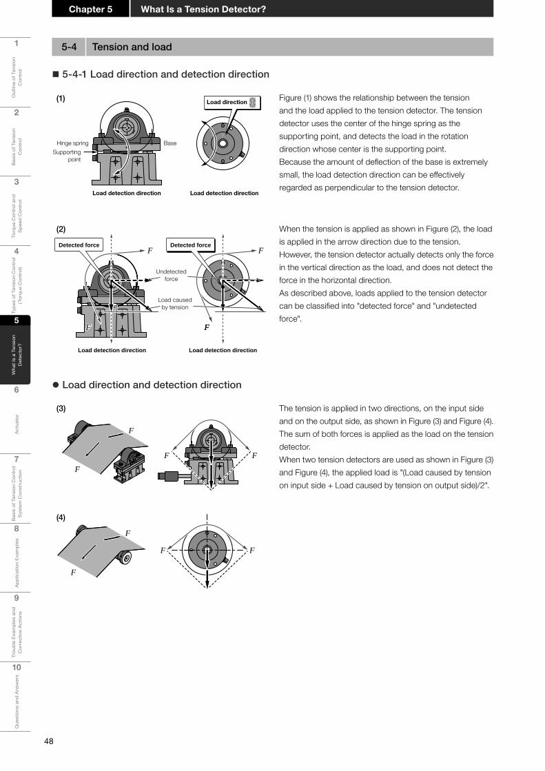
48
1
Out
line
of T
ensi
on
Con
trol
2
Bas
is o
f Ten
sion
C
ontr
ol
3
Torq
ue C
ontr
ol a
nd
Spe
ed C
ontr
ol
4
Type
s of
Ten
sion
Con
trol
(T
orqu
e C
ontr
ol)
5
Wha
t Is
a Te
nsio
n D
etec
tor?
6
Act
uato
r
7
Bas
is o
f Ten
sion
Con
trol
S
yste
m C
onst
ruct
ion
8
App
licat
ion
Exam
ples
9
Trou
ble
Exam
ples
and
C
orre
ctiv
e A
ctio
ns
10
Que
stio
ns a
nd A
nsw
ers
What Is a Tension Detector?Chapter 5
5-4 Tension and load
Figure (1) shows the relationship between the tension and the load applied to the tension detector. The tension detector uses the center of the hinge spring as the supporting point, and detects the load in the rotation direction whose center is the supporting point.Because the amount of deflection of the base is extremely small, the load detection direction can be effectively regarded as perpendicular to the tension detector.
� 5-4-1 Load direction and detection direction
z Load direction and detection direction
Load detection direction Load detection direction
Hinge spring BaseSupporting
point
Load direction
When the tension is applied as shown in Figure (2), the load is applied in the arrow direction due to the tension.However, the tension detector actually detects only the force in the vertical direction as the load, and does not detect the force in the horizontal direction.As described above, loads applied to the tension detector can be classified into "detected force" and "undetected force".
Load detection direction
F
FF
Detected forceDetected force
Load detection direction
Undetectedforce
Load causedby tension
F
F
F
F
FF
The tension is applied in two directions, on the input side and on the output side, as shown in Figure (3) and Figure (4).The sum of both forces is applied as the load on the tension detector.When two tension detectors are used as shown in Figure (3) and Figure (4), the applied load is "(Load caused by tension on input side + Load caused by tension on output side)/2".
(2)
(3)
(1)
F
F
FF
(4)

49
1
Out
line
of T
ensi
on
Con
trol
2
Bas
is o
f Ten
sion
C
ontr
ol
3
Torq
ue C
ontr
ol a
nd
Spe
ed C
ontr
ol
4
Type
s of
Ten
sion
Con
trol
(T
orqu
e C
ontr
ol)
5
Wha
t Is
a Te
nsio
n D
etec
tor?
6
Act
uato
r
7
Bas
is o
f Ten
sion
Con
trol
S
yste
m C
onst
ruct
ion
8A
pplic
atio
n Ex
ampl
es
9
Trou
ble
Exam
ples
and
C
orre
ctiv
e A
ctio
ns
10
Que
stio
ns a
nd A
nsw
ers
Chapter 5What Is a Tension Detector?
5-5 Cautions on attaching the tension detector
� 5-5-1 How to attach the tension detector (Stationary type)
Pillow blockt
Pillow block mounting bolt
Tension detection roller
Because the tension detector is highly sensitive equipment manufactured by precise processing and assembly, care is required when attaching it.
(1) Attachment using the standard pillow block
The pillow block and pillow block mounting bolts are not provided as standard accessories.Make sure that the length of the pillow block mounting bolts does not exceed the thickness "t" of the mounting base on the tension detector side.If the length of the bolts exceeds "t", the bolts will touch the inside of the tension detector, may hinder accurate detection, and may cause a failure.
(2) Attachment using the optional plate
The pillow block and pillow block mounting bolts are not provided as standard accessories.The optional plate mounting bolts are provided as accessories with the optional plate.
Pillow blockmounting bolt
Optional platemounting bolt
Optional plate
z Using the automatic aligning pillow block
Automatic aligning pillow block
Make sure to use the automatic aligning pillow block as the bearing so that machining errors including imbalanced tension detection roller and non-parallel sensor mounting face and changes in the roller length caused by temperature changes are not detected as the tension.The automatic aligning pillow block can mitigate the stress caused by the inclination of the tension detection roller and the effect of deviated material path and uneven thickness.
Inclination of the tension detection roller Deviated material path Only one tension detector
The pillow block can mitigate the effect of deviated material path (when the edge position control is used) and of uneven thickness.
The pillow block can mitigate the effect of the inclination of the tension detection roller when only one tension detector is used.
The pillow block can mitigate the stress caused by the inclination of the tension detection roller.
(1)
(2)
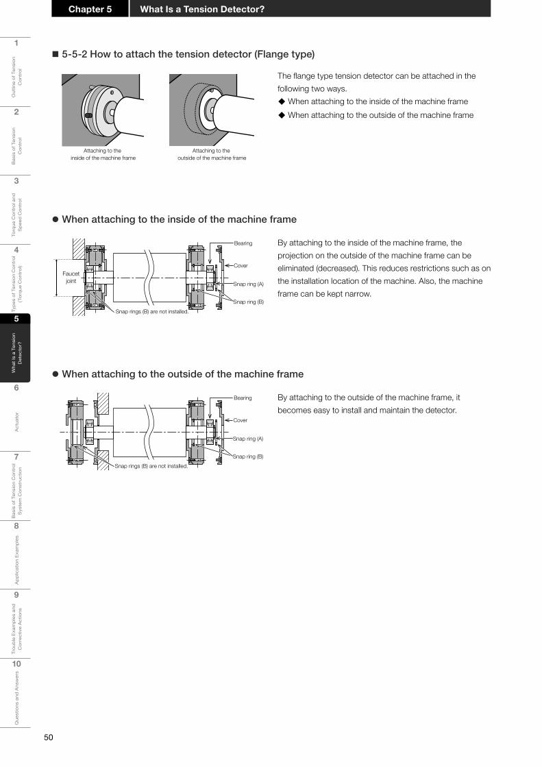
50
1
Out
line
of T
ensi
on
Con
trol
2
Bas
is o
f Ten
sion
C
ontr
ol
3
Torq
ue C
ontr
ol a
nd
Spe
ed C
ontr
ol
4
Type
s of
Ten
sion
Con
trol
(T
orqu
e C
ontr
ol)
5
Wha
t Is
a Te
nsio
n D
etec
tor?
6
Act
uato
r
7
Bas
is o
f Ten
sion
Con
trol
S
yste
m C
onst
ruct
ion
8
App
licat
ion
Exam
ples
9
Trou
ble
Exam
ples
and
C
orre
ctiv
e A
ctio
ns
10
Que
stio
ns a
nd A
nsw
ers
What Is a Tension Detector?Chapter 5
� 5-5-2 How to attach the tension detector (Flange type)
The flange type tension detector can be attached in the following two ways.
� When attaching to the inside of the machine frame � When attaching to the outside of the machine frame
By attaching to the inside of the machine frame, the projection on the outside of the machine frame can be eliminated (decreased). This reduces restrictions such as on the installation location of the machine. Also, the machine frame can be kept narrow.
z When attaching to the inside of the machine frame
By attaching to the outside of the machine frame, it becomes easy to install and maintain the detector.
z When attaching to the outside of the machine frame
Attaching to the inside of the machine frame
Attaching to the outside of the machine frame
Faucetjoint
Bearing
Cover
Snap ring (A)
Snap ring (B)Snap rings (B) are not installed.
Snap rings (B) are not installed.
Bearing
Cover
Snap ring (A)
Snap ring (B)

51
1
Out
line
of T
ensi
on
Con
trol
2
Bas
is o
f Ten
sion
C
ontr
ol
3
Torq
ue C
ontr
ol a
nd
Spe
ed C
ontr
ol
4
Type
s of
Ten
sion
Con
trol
(T
orqu
e C
ontr
ol)
5
Wha
t Is
a Te
nsio
n D
etec
tor?
6
Act
uato
r
7
Bas
is o
f Ten
sion
Con
trol
S
yste
m C
onst
ruct
ion
8A
pplic
atio
n Ex
ampl
es
9
Trou
ble
Exam
ples
and
C
orre
ctiv
e A
ctio
ns
10
Que
stio
ns a
nd A
nsw
ers
Chapter 5What Is a Tension Detector?
� 5-5-3 Cautions on attaching the tension detector
When supporting the tension detection roller at both ends, align the height of the tension detector mounting face.Minimize the dimension marked with "*" to reduce the tension detection error.If the dimension marked with "*" is large, the material may meander, the bearing life may be shortened, and the zero-point output may change.When using the spacer for aligning the height, make sure that the shape of the spacer can cover the entire mounting face.
When using the tension detector in an environment with large temperature changes, install a mechanism to absorb changes in the tension detection roller length caused by temperature changes so that the tension detection accuracy is not affected.For example, the effect of elongation/shrinkage of the tension detection roller can be mitigated by loosening only one set screw used to fix the tension detection roller shaft in the bearing inner ring.
z When using in an environment with large temperature changes
Elongation/shrinkage of the tension detection roller
Set screwSet screw
The effect of elongation/shrinkage of the tension detection roller caused by changes in the ambient temperature can be mitigated.
Stationary tension detector
*
*
Point! LX-TD tension detector
When the material is wide, use two LX-TD tension detectors in total, one at each end of the tension detection roller, so that the tension across the full width can be detected accurately even if the material is stretched on only one side.Only one LX-TD tension detector may be installed on either side when the material is not stretched on one side.Use two LX7-F tension detectors in total, one at each end.
For the flange type tension detector, be sure to use self-aligning bearings. Using the automatic aligning bearings can mitigate the stress caused by the inclination of the tension detection roller and the effects of deviated material path and uneven thickness.
In the case of the flange type tension detector, attaching the snap ring (B) only to the tension detector on the right side enables the tension detector on the left side to slide without being fixed in the left and right directions, thus relieving the effect of expansion and contraction of the tension detection roller due to changes in the ambient temperature.
*
*
Flange type tension detector
Automatic aligning bearings
Snap rings (B) are not installed.Snap ring (B)

52
1
Out
line
of T
ensi
on
Con
trol
2
Bas
is o
f Ten
sion
C
ontr
ol
3
Torq
ue C
ontr
ol a
nd
Spe
ed C
ontr
ol
4
Type
s of
Ten
sion
Con
trol
(T
orqu
e C
ontr
ol)
5
Wha
t Is
a Te
nsio
n D
etec
tor?
6
Act
uato
r
7
Bas
is o
f Ten
sion
Con
trol
S
yste
m C
onst
ruct
ion
8
App
licat
ion
Exam
ples
9
Trou
ble
Exam
ples
and
C
orre
ctiv
e A
ctio
ns
10
Que
stio
ns a
nd A
nsw
ers
What Is a Tension Detector?Chapter 5
z Usage precautions
LX7-F flange-type tension detector is a precision device.Especially, the sensor part can be damaged by impact or disassembly. Please handle with care.
Do not drop the tension detector.
(1)
Do not touch or press the sensor part (1).
(2)
Do not loosen the sensormounting screw (2).
Do not hit the tension detectorwhen installing the tension detector to the device and when installing bearing/shaft to the tension detector.
Do not hit the tension detector when performing centering adjustment.
Do not pry the shaft.
Do not apply a load whichexceeds the maximum load(200% of rated load) wheninstalling and arranging the tension detector.Do not use the tension detection roller as a foothold while working.

Chapter 6
Actuator
6-1 Types and features of actuators6-2 Powder clutch/brake6-3 AC servo motor and inverter/motor6-4 Air clutches/brakes (manufactured by other
companies)6-5 Differencesbetweencontrolusingmotors
and control using powder6-6 Actuatorselectionflow6-7 Selecting an actuator

54
1
Out
line
of T
ensi
on
Con
trol
2
Bas
is o
f Ten
sion
C
ontr
ol
3
Torq
ue C
ontr
ol a
nd
Spe
ed C
ontr
ol
4
Type
s of
Ten
sion
Con
trol
(T
orqu
e C
ontr
ol)
5
Wha
t Is
a Te
nsio
n D
etec
tor?
6
Act
uato
r
7
Bas
is o
f Ten
sion
Con
trol
S
yste
m C
onst
ruct
ion
8
App
licat
ion
Exam
ples
9
Trou
ble
Exam
ples
and
C
orre
ctiv
e A
ctio
ns
10
Que
stio
ns a
nd A
nsw
ers
ActuatorChapter 6
ActuatorChapter
6Motors, clutches, brakes, etc. which move machines are called actuators.
Because each actuator has advantages and disadvantages, it is necessary to select proper actuators in accordance with the purpose.
6-1 Types and features of actuators
1234 Strongly agree
Strongly disagree
Item Type Powderclutch/brake
Airclutch/brake AC servo motor Inverter
(Vector control)
Torque linearity 3 3 4 4Torque
reproducibility 3 2 4 4Torque
control range4
(1 to 100%)3
(5 to 100%)4
(1 to 100%)3
(2 to 100%)
Life 3(Powder)
2(Pad)
4 4
Installation cost 4 4 1 2
Line speed Low to medium High High Medium to high
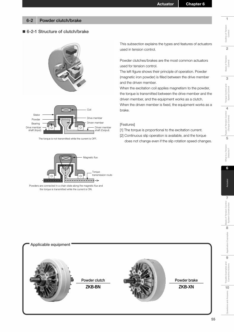
55
1
Out
line
of T
ensi
on
Con
trol
2
Bas
is o
f Ten
sion
C
ontr
ol
3
Torq
ue C
ontr
ol a
nd
Spe
ed C
ontr
ol
4
Type
s of
Ten
sion
Con
trol
(T
orqu
e C
ontr
ol)
5
Wha
t Is
a Te
nsio
n D
etec
tor?
6
Act
uato
r
7
Bas
is o
f Ten
sion
Con
trol
S
yste
m C
onst
ruct
ion
8A
pplic
atio
n Ex
ampl
es
9
Trou
ble
Exam
ples
and
C
orre
ctiv
e A
ctio
ns
10
Que
stio
ns a
nd A
nsw
ers
Chapter 6Actuator
� 6-2-1 Structure of clutch/brake
Coil
Drive member
Driven member
Driven membershaft (Output)
Drive membershaft (Input)
BearingPowder
Stator
The torque is not transmitted while the current is OFF.
This subsection explains the types and features of actuators used in tension control.
Powder clutches/brakes are the most common actuators used for tension control.The left figure shows their principle of operation. Powder (magnetic iron powder) is filled between the drive member and the driven member.When the excitation coil applies magnetism to the powder, the torque is transmitted between the drive member and the driven member, and the equipment works as a clutch.When the driven member is fixed, the equipment works as a brake.
Magnetic flux
Torquetransmission route
Powders are connected in a chain state along the magnetic flux andthe torque is transmitted while the current is ON.
[Features][1] The torque is proportional to the excitation current.[2] Continuous slip operation is available, and the torque
does not change even if the slip rotation speed changes.
6-2 Powder clutch/brake
Applicable equipment
Powder clutchZKB-BN
Powder brakeZKB-XN

56
1
Out
line
of T
ensi
on
Con
trol
2
Bas
is o
f Ten
sion
C
ontr
ol
3
Torq
ue C
ontr
ol a
nd
Spe
ed C
ontr
ol
4
Type
s of
Ten
sion
Con
trol
(T
orqu
e C
ontr
ol)
5
Wha
t Is
a Te
nsio
n D
etec
tor?
6
Act
uato
r
7
Bas
is o
f Ten
sion
Con
trol
S
yste
m C
onst
ruct
ion
8
App
licat
ion
Exam
ples
9
Trou
ble
Exam
ples
and
C
orre
ctiv
e A
ctio
ns
10
Que
stio
ns a
nd A
nsw
ers
ActuatorChapter 6
[Running-inoperation]
Powder inside the powder clutch/brake is distributed unevenly due to shocks applied during transportation, etc. Perform the running-in operation before starting regular operation.
To attain the original performance of the powder clutch/brake, it is important that the powder is distributed evenly inside the powder gap.If powder is distributed unevenly, the torque may become lower, fluctuate or become uneven. As a result, the powder clutch/brake cannot deliver its original performance.
The running-in operation makes unevenly distributed powder distributed evenly inside the powder gap to generate stable torque in proportion to the excitation current.Refer to the corresponding catalog or instruction manual for the running-in operation procedure.
Befo
re ru
nnin
g-in
Afte
r run
ning
-in
Powder gap
Driven member
Powder
Drive member
Powders are accumulated at the bottom due to shocksapplied during transportation, etc.
Powders are distributed evenly inside the powder gap.
Powder gap
Driven member
Powder
Drive member
� 6-2-2 Cautions on using powder clutches/brakes
[Installation]
OutputInput
Elastic coupling
Horizontal
Shaft
• Using the high-speed rotation side as the input side
Use the powder clutch in the regular installation status in which the high-speed rotation side is set as the input side.It is not recommended to use the powder clutch in the reverse installation status for continuous idling because the torque characteristics may deteriorate and the powder life may be shortened.
• How to connect the input shaft and output shaft of the powder clutch/brake
There are mainly two methods to connect the powder clutch/brake shaft and load shaft: the method using a coupling and the method using a belt and chain.In the connection method using a coupling, use an elastic coupling, and make sure that the concentricity and squareness between the two shafts meet the values allowed for the elastic coupling that is used.In the connection method using a belt and chain, make sure that the load applied to the shaft is less than the allowable shaft load determined in accordance with the shaft strength and allowable radial load of the bearing.Refer to the corresponding catalog for the allowable shaft load.
Elastic coupling
Belt

57
1
Out
line
of T
ensi
on
Con
trol
2
Bas
is o
f Ten
sion
C
ontr
ol
3
Torq
ue C
ontr
ol a
nd
Spe
ed C
ontr
ol
4
Type
s of
Ten
sion
Con
trol
(T
orqu
e C
ontr
ol)
5
Wha
t Is
a Te
nsio
n D
etec
tor?
6
Act
uato
r
7
Bas
is o
f Ten
sion
Con
trol
S
yste
m C
onst
ruct
ion
8A
pplic
atio
n Ex
ampl
es
9
Trou
ble
Exam
ples
and
C
orre
ctiv
e A
ctio
ns
10
Que
stio
ns a
nd A
nsw
ers
Chapter 6Actuator
The minimum rotation speed required for operation is determined in the powder clutch/brake. In the powder brake, the minimum rotation speed is 15 r/min. In the powder clutch, the minimum difference in the rotation speed between the input and the output is 15 r/min.(This means that both the powder clutch and the powder brake require a slip rotation speed of 15 r/min or more.)If the slipping rotation speed is low, internal powder may be distributed unevenly and stable torque performance may not be obtained, or a considerable time may be required until the prescribed torque is achieved at startup.The ZKB, ZKG and ZX type powder clutches/brakes can be used when the slip rotation speed becomes approximately 5 r/min.
Powder gap
Driven member
Powder
Drive member
Q If the rotation speed is low
Powders are distributed evenly.
Q If the rotation speed is high
[Moistureabsorptionofpowder]The performance of the powder clutch/brake may be unstable if the powder becomes wet. Take care to ensure that water, oil, etc. does not enter the inside.Especially when the powder clutch/brake is installed near the gear box, oil may enter the inside via the shaft. Perform complete sealing.Because the powder clutch/brake does not have a sealed structure, it cannot be used in an environment in which it is directly exposed to oil mist, oil or water.
Powders becomewet.
Water
Oil
[Idlingtorque]Even if the excitation current is shut down completely, idling torque is generated in the powder clutch/brake due to the magnetism remaining in components and the friction of the powder and bearing.Torque control is available at a torque larger than the idling torque. Refer to the corresponding catalog for the idling torque shown for each model.
Idling torque ≤ Available torque ≤ Rated torque
BearingPowders
Friction of powders and bearing
[Simpletorquemeasurementmethod]Read the value indicated by the spring balance while pulling up the spring balance at a constant speed as shown in the left figure.(Measure the torque during rotation in the power-on status after the running-in operation.)
Spring balance (W [N] )Spring balance (W [N] )Spring balance (W [N] )
Reel shaft (Outside diameter D [m] )
Powder brakePowder brakePowder brake
Wind a proper stringby several turns.Wind a proper stringby several turns.Wind a proper stringby several turns.
[Minimumrotationspeed]
Powder brakes The rotation speed should be 15 r/min or more.
Powder clutches The difference in the rotation speed between the input and the output should be 15 r/min or more.
Torque(T)=W× [Nm]D2

58
1
Out
line
of T
ensi
on
Con
trol
2
Bas
is o
f Ten
sion
C
ontr
ol
3
Torq
ue C
ontr
ol a
nd
Spe
ed C
ontr
ol
4
Type
s of
Ten
sion
Con
trol
(T
orqu
e C
ontr
ol)
5
Wha
t Is
a Te
nsio
n D
etec
tor?
6
Act
uato
r
7
Bas
is o
f Ten
sion
Con
trol
S
yste
m C
onst
ruct
ion
8
App
licat
ion
Exam
ples
9
Trou
ble
Exam
ples
and
C
orre
ctiv
e A
ctio
ns
10
Que
stio
ns a
nd A
nsw
ers
ActuatorChapter 6
The Mitsubishi Electric MELSERVO-J4 Series AC servo motors and FR-A800 Series general-purpose inverters can be operated in torque control mode to perform winding and unwinding.In torque control mode, servo motors and inverters/motors are controlled so that a torque proportional to the command input is obtained. Accordingly, it is possible to obtain a constant tension by giving the command input in proportion to the reel diameter.
¯What is an AC servo motor? ¯What is an inverter? ¯What is an inverter (vector control)?
• An inverter for motor control refers to a device which changes the power frequency of a motor (generally, an induction motor) to change the rotation speed of the motor.
• Each manufacturer generally classifies inverters into several ranks by the motor control function.
• Inverters (vector control) can control the position (motor rotation angle), rotation speed and rotation force (torque).
• Inverters (vector control) can achieve higher-quality control than general-purpose inverters for motor control though the accuracy is lower than that of AC servo motors.
• In tension control, inverters (vector control) offer higher stability of rotation speed because the inertia inside the motor is larger than that of AC servo motors.
• Inverters (vector control) offer smoother transition between the power running torque region and the regenerative torque region than AC servo motors.
• Commands refer to the position (motor rotation angle), rotation speed and rotation force (torque).
• The motor status in response to a command is fed back and controlled.
• A servo motor having a synchronous motor is called an AC servo motor in Mitsubishi Electric Corporation.
• An AC servo motor is a kind of inverter in a broad sense.
An inverter is a device used to convert frequency.
An inverter (vector control) refers to an induction motor combined with an encoder for detecting the position/rotation speed and a cooling fan.
A servo motor is a motor controlled so as to comply faithfully with commands.
� 6-3-1 What are an AC servo motor and inverter/motor?
6-3 AC servo motor and inverter/motor
Applicable equipment
AC servo motorMELSERVO-J4
Inverter(for vector control)
FR-A800

59
1
Out
line
of T
ensi
on
Con
trol
2
Bas
is o
f Ten
sion
C
ontr
ol
3
Torq
ue C
ontr
ol a
nd
Spe
ed C
ontr
ol
4
Type
s of
Ten
sion
Con
trol
(T
orqu
e C
ontr
ol)
5
Wha
t Is
a Te
nsio
n D
etec
tor?
6
Act
uato
r
7
Bas
is o
f Ten
sion
Con
trol
S
yste
m C
onst
ruct
ion
8A
pplic
atio
n Ex
ampl
es
9
Trou
ble
Exam
ples
and
C
orre
ctiv
e A
ctio
ns
10
Que
stio
ns a
nd A
nsw
ers
Chapter 6Actuator
� 6-3-2 Cautions on using the AC servo motor and inverter (vector control)/motor[1] The nominal motor output is determined by the rated
rotation speed and output torque in continuous operation at the rated rotation speed.
Large torque is required at the maximum reel diameter in winding and rewinding, and the rotation speed becomes high at the minimum reel diameter. This means that a large-capacity motor is required when the reel diameter ratio (ratio between the maximum reel diameter and the minimum reel diameter) is high.
However, the motor capacity can be reduced in some cases by utilizing the constant output area. For winding and unwinding, a vector motor that can take a wide constant output area is effective.
[2] For tension control, the rated torque, not the short-time maximum torque, should be examined in the motor.
[3] Compared with the AC servo motor, the start-up delay of the motor during winding control of low tension and small reel diameter may be a problem. Care must be taken when selecting the capacity and gear ratio in winding control with large torque ratio (maximum reel diameter/minimum reel diameter × maximum tension/minimum tension).
[4] AC servo motors are generally suitable for use at high rotation speed. Their output torque is extremely small compared with powder clutches/brakes, and speed reducers are required to drive the reel shaft. If the gear ratio of the speed reducers is too high, accurate tension control cannot be achieved.
[5] When the torque command crosses the regenerative area and power running area, AC servo motors are not suitable for control requiring high accuracy because the torque linearity is not good.
[6] AC servo motors are not suitable for use at low speed because cogging torque is generated in the low-speed area.
[7] In AC servo motors, the recommended value of the load inertia moment ratio is determined for winding and unwinding against the inertia moment of motors.
Refer to the corresponding catalog for details.
1500
50
150
100
75
03000
100
300
40000 3000 500
150
100
120
0
2530
37.5
2000
Torq
ue (%
)
Torq
ue (%
)
Torq
ue (%
)
Short-time maximum torque
Torque in continuous operation
Rotation speed (r/min) Rotation speed (r/min) Rotation speed (r/min)
Short-timemaximum torque(SF-V5RU□K3Y)
Torque incontinuousoperation Constant output Constant output
Torque incontinuousoperation
Short-time maximum torque(SF-V5RU□K4Y)
Short-time maximum torque(SF-V5RU□K4)
Inverter/motor AC servo motor

60
1
Out
line
of T
ensi
on
Con
trol
2
Bas
is o
f Ten
sion
C
ontr
ol
3
Torq
ue C
ontr
ol a
nd
Spe
ed C
ontr
ol
4
Type
s of
Ten
sion
Con
trol
(T
orqu
e C
ontr
ol)
5
Wha
t Is
a Te
nsio
n D
etec
tor?
6
Act
uato
r
7
Bas
is o
f Ten
sion
Con
trol
S
yste
m C
onst
ruct
ion
8
App
licat
ion
Exam
ples
9
Trou
ble
Exam
ples
and
C
orre
ctiv
e A
ctio
ns
10
Que
stio
ns a
nd A
nsw
ers
ActuatorChapter 6
Tension controller
Air brake (manufactured by another company)
Electro-pneumatic converter(manufactured by another company)
Tension detector
Air clutches/brakes (manufactured by other companies) transmit the torque by pressing the friction plate with air.Air clutches/brakes are used for winding and unwinding with relatively large torque and heat capacity compared with powder clutches/brakes. In this case, a Mitsubishi Electric tension controller can be used via an electro-pneumatic converter.
[Features] • The torque is almost proportional to the air pressure.
• The torque can be changed by changing the number of calipers.
• The torque changes in accordance with the slip rotation speed.
• Friction powder is generated from the calipers and disc.
6-4 Air clutches/brakes (manufactured by other companies)

61
1
Out
line
of T
ensi
on
Con
trol
2
Bas
is o
f Ten
sion
C
ontr
ol
3
Torq
ue C
ontr
ol a
nd
Spe
ed C
ontr
ol
4
Type
s of
Ten
sion
Con
trol
(T
orqu
e C
ontr
ol)
5
Wha
t Is
a Te
nsio
n D
etec
tor?
6
Act
uato
r
7
Bas
is o
f Ten
sion
Con
trol
S
yste
m C
onst
ruct
ion
8A
pplic
atio
n Ex
ampl
es
9
Trou
ble
Exam
ples
and
C
orre
ctiv
e A
ctio
ns
10
Que
stio
ns a
nd A
nsw
ers
Chapter 6Actuator
• Control using motors
Motors are used on the side rotating the load (power running side) and the side rotated by the load (regenerative side).When motors are used for winding and unwinding:Winding side: Side rotating the load (power running side) Unwinding side: Side rotated by the load (regenerative side)On the regenerative side, the motor works as a generator, and generates electrical energy. Because the generated electrical energy returns to the AC servo amplifier or inverter, it is necessary to release it by returning it to heat or power. The regenerative unit or regenerative converter is used for this purpose.Motor
Motor
Inverter Regenerative unit
Regeneration
Powerrunning
• Control using powder
Powder brake
Powder clutch
Winding motor
When driving the motor with an inverter, the torque may be insufficient if the rotation speed is low, so the tendency is to increase the gear ratio.However, if the gear ratio is too high, mechanical loss and torque fluctuation may increase.In the AC servo motor, torque ripple (torque unevenness) is generated due to the switching of the motor magnetic pole at low rotation speed.Motors are not perfect, and it is necessary to select a proper actuator in accordance with the usage conditions.
[Rotation speed]
[Powder clutch and powder brake]
The clutch is generally used for winding in combination with a motor.The clutch is sometimes used for unwinding in combination with a reverse rotation motor when the line speed is low.The clutch transmits the motor power to the load shaft, or shuts down the motor power.One of the features of the powder clutch is that it can transmit power while slipping. Accordingly, the powder clutch can make the rotation speed extremely low or zero on the load shaft side, which cannot be achieved by control using motors.However, slip changes into heat energy and generates heat. The brake applies braking to the power of the load shaft. Because the powder brake applies braking with slipping, slip changes into heat energy and generates heat. The generated heat reduces the powder life. In addition, it is necessary to observe the restriction on heat generation (allowable heat dissipation).
6-5 Differencesbetweencontrolusingmotorsandcontrolusingpowder

62
1
Out
line
of T
ensi
on
Con
trol
2
Bas
is o
f Ten
sion
C
ontr
ol
3
Torq
ue C
ontr
ol a
nd
Spe
ed C
ontr
ol
4
Type
s of
Ten
sion
Con
trol
(T
orqu
e C
ontr
ol)
5
Wha
t Is
a Te
nsio
n D
etec
tor?
6
Act
uato
r
7
Bas
is o
f Ten
sion
Con
trol
S
yste
m C
onst
ruct
ion
8
App
licat
ion
Exam
ples
9
Trou
ble
Exam
ples
and
C
orre
ctiv
e A
ctio
ns
10
Que
stio
ns a
nd A
nsw
ers
ActuatorChapter 6
The above figure shows the flow of selecting an actuator.First, confirm the machine specifications, and calculate the approximate capacity of the actuator. Next, temporarily select the model in accordance with the load shaft, torque and rotation speed. Finally, set the gear ratio, and confirm that the torque, rotation speed and capacity of the actuator shaft are acceptable.
[1] Confirming the machine specifications
[2] Confirming the approximate actuator capacity
[3] Calculating the load torque and rotation speed
[4] Confirming the drive shaft torque and rotation speed range
[5] Temporarily selecting the model
[6] Selecting the gear ratio
[7] Calculating the torque,rotation speed and regeneration capacity(heat generation quantity)of the actuator shaft
[8] Confirming the torque range and rotation speed range of the actuator shaft
[9] Determining the input rotation speed for the clutch/brake
[10] Confirming the allowable heat generation capacity
Material speed, tension, reel diameter,roller diameter, etc.
Heat generation quantity, regenerationcapacity and motor capacity
Reel shaft torque, roller torque and rotation speed
Checking the torque range
Confirming the rotation speed range
Temporarily determining the actuator model
Determining the gear ratio betweenthe load shaft and the actuator shaft
Confirming the gear ratio
Torque, rotation speed and heat generationquantity of the actuator shaft
Checking the torque range
Confirming the rotation speed range
Input rotation speed for the clutch/brake
Selection is completed.
Confirming the heat generation capacity
* Only in clutch/brake
Reexamining the machinespecifications
The actuatormodelcan be
changed.
Reexamining the gear ratio
The gearratio can be
changed.
Changingthe actuator
model
YES
YES
YES
YES
NO
NO
NO
YES
YES
NO
NO
NO
6-6 Actuatorselectionflow

63
1
Out
line
of T
ensi
on
Con
trol
2
Bas
is o
f Ten
sion
C
ontr
ol
3
Torq
ue C
ontr
ol a
nd
Spe
ed C
ontr
ol
4
Type
s of
Ten
sion
Con
trol
(T
orqu
e C
ontr
ol)
5
Wha
t Is
a Te
nsio
n D
etec
tor?
6
Act
uato
r
7
Bas
is o
f Ten
sion
Con
trol
S
yste
m C
onst
ruct
ion
8A
pplic
atio
n Ex
ampl
es
9
Trou
ble
Exam
ples
and
C
orre
ctiv
e A
ctio
ns
10
Que
stio
ns a
nd A
nsw
ers
Chapter 6Actuator
This subsection shows a calculation example of a powder brake for unwinding.Calculate the torque, rotation speed and heat dissipation based on the usage conditions.The maximum value and minimum value of the braking torque required at the start and end of unwinding can be obtained as follows:
Tmax = ×Fmax =Dmax
20.25
2 ×80 = 10 Nm
Tmin = ×Fmin =Dmin
20.075
2 ×40 = 1.5 Nm
The maximum value and minimum value of the rotation speed can be obtained as follows:
Nmax = =Vmax
(π×Dmin)15
(π×0.075) = 63.7 r/min
Nmin = =Vmin
(π×Dmax)5
(π×0.25) = 6.4 r/min
The heat dissipation can be obtained as follows:
P = 0.105×T×N = 0.0167×F×V=0.0167×80×15 = 20 W
Select a proper powder brake model based on the above calculation results.Select a model such that the torque, rotation speed and heat dissipation do not exceed the allowable values.In these conditions, the model ZKB-1.2XN is available.
� 6-7-1 Powder brake for unwinding
V
D
F
Usage conditionsTension (F) 40 to 80 N
Reel diameter (D) 75 to 250 mmLine speed (V) 5 to 15 m/minReduction ratio 1
6-7 Selecting an actuator
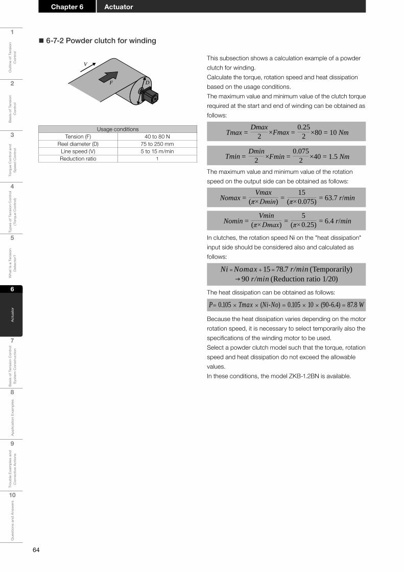
64
1
Out
line
of T
ensi
on
Con
trol
2
Bas
is o
f Ten
sion
C
ontr
ol
3
Torq
ue C
ontr
ol a
nd
Spe
ed C
ontr
ol
4
Type
s of
Ten
sion
Con
trol
(T
orqu
e C
ontr
ol)
5
Wha
t Is
a Te
nsio
n D
etec
tor?
6
Act
uato
r
7
Bas
is o
f Ten
sion
Con
trol
S
yste
m C
onst
ruct
ion
8
App
licat
ion
Exam
ples
9
Trou
ble
Exam
ples
and
C
orre
ctiv
e A
ctio
ns
10
Que
stio
ns a
nd A
nsw
ers
ActuatorChapter 6
� 6-7-2 Powder clutch for winding
This subsection shows a calculation example of a powder clutch for winding.Calculate the torque, rotation speed and heat dissipation based on the usage conditions.The maximum value and minimum value of the clutch torque required at the start and end of winding can be obtained as follows:
Tmax = ×Fmax =Dmax
20.25
2 ×80 = 10 Nm
Tmin = ×Fmin =Dmin
20.075
2 ×40 = 1.5 Nm
The maximum value and minimum value of the rotation speed on the output side can be obtained as follows:
Nomax = =Vmax
(π×Dmin)15
(π×0.075) = 63.7 r/min
Nomin = =Vmin
(π×Dmax)5
(π×0.25) = 6.4 r/min
In clutches, the rotation speed Ni on the "heat dissipation" input side should be considered also and calculated as follows:
Ni = Nomax + 15 = 78.7 r/min (Temporarily) g 90 r/min (Reduction ratio 1/20)
The heat dissipation can be obtained as follows:
P= 0.105 × Tmax × (Ni-No) = 0.105 × 10 × (90-6.4) = 87.8 W
Because the heat dissipation varies depending on the motor rotation speed, it is necessary to select temporarily also the specifications of the winding motor to be used.Select a powder clutch model such that the torque, rotation speed and heat dissipation do not exceed the allowable values.In these conditions, the model ZKB-1.2BN is available.
V
F D
Usage conditionsTension (F) 40 to 80 N
Reel diameter (D) 75 to 250 mmLine speed (V) 5 to 15 m/minReduction ratio 1

65
1
Out
line
of T
ensi
on
Con
trol
2
Bas
is o
f Ten
sion
C
ontr
ol
3
Torq
ue C
ontr
ol a
nd
Spe
ed C
ontr
ol
4
Type
s of
Ten
sion
Con
trol
(T
orqu
e C
ontr
ol)
5
Wha
t Is
a Te
nsio
n D
etec
tor?
6
Act
uato
r
7
Bas
is o
f Ten
sion
Con
trol
S
yste
m C
onst
ruct
ion
8A
pplic
atio
n Ex
ampl
es
9
Trou
ble
Exam
ples
and
C
orre
ctiv
e A
ctio
ns
10
Que
stio
ns a
nd A
nsw
ers
Chapter 6Actuator
Q Selecting the winding motor
Output: 0.2 kWReduction ratio: 1/20
[Gearedmotorselectionresult]
Rotation speed: 90 r/min → Reduction ratio: 1/20Torque: 10.0 Nm×2 →20 Nm or more
Safety factor
[Gearedmotorselectionconditions]
Output (kW)
Rotation speed of output shaft (r/min)
Nominal reduction
ratio
Actual reduction
ratio
Allowable torque of output shaft (Nm)
50 Hz 60 Hz 50 Hz 60 Hz
0.2
500 600 1/3 1/3.07 3.5 2.9300 360 1/5 1/4.97 5.9 4.9150 180 1/10 1/9.93 12 9.8100 120 1/15 1/14.81 18 1575 90 1/20 1/20.08 24 2060 72 1/25 1/23.85 29 2550 60 1/30 1/28.88 33 2937.5 45 1/40 1/41.07 47 3930 36 1/50 1/48.96 59 49
···
[GM-Scharacteristicstable]

66
1
Out
line
of T
ensi
on
Con
trol
2
Bas
is o
f Ten
sion
C
ontr
ol
3
Torq
ue C
ontr
ol a
nd
Spe
ed C
ontr
ol
4
Type
s of
Ten
sion
Con
trol
(T
orqu
e C
ontr
ol)
5
Wha
t Is
a Te
nsio
n D
etec
tor?
6
Act
uato
r
7
Bas
is o
f Ten
sion
Con
trol
S
yste
m C
onst
ruct
ion
8
App
licat
ion
Exam
ples
9
Trou
ble
Exam
ples
and
C
orre
ctiv
e A
ctio
ns
10
Que
stio
ns a
nd A
nsw
ers
ActuatorChapter 6
When the line speed is extremely low during unwinding, the input rotation speed may be lower than the minimum rotation speed in the powder brake.In such a case, replace the powder brake with the combination of "powder clutch and reverse rotation motor". It is called reverse rotation input because the motor rotates in the reverse direction of the reel shaft rotation direction.Connect the output side (or input side) of the powder clutch to the unwinding reel shaft, connect the geared motor to the input side (or output side), and then always rotate the geared motor in the direction reverse to the rotation direction of the unwinding reel shaft. By this configuration, sufficient slip rotation speed can be secured, and stable torque control is achieved.With regard to the powder clutch installation direction, usually connect its input side to the side of higher rotation speed. For example, when the line speed is low and the rotation speed of the unwinding reel shaft is always low, connect the input side of the powder clutch to the motor.When the reel diameter at the start of unwinding is large and sufficient slip rotation speed can be obtained during almost all operation time even though the rotation speed is temporarily low at the start of unwinding, connect the output side of the powder clutch to the motor.
z What is reverse rotation input?
Powder clutch
Reverse rotation motor
Reverserotation input
Powder brake
Normalrotation input
� Unwinding side (Powder brake)
When the input rotation speed is lower than the minimum rotation speed in the powder brake
In this case, replace the powder brake with the combination of "powder clutch + reverse rotation motor".
Minimum rotation speed Model
5 r/min or less → ZKG, ZKB or ZX
15 r/min or less → ZA

67
1
Out
line
of T
ensi
on
Con
trol
2
Bas
is o
f Ten
sion
C
ontr
ol
3
Torq
ue C
ontr
ol a
nd
Spe
ed C
ontr
ol
4
Type
s of
Ten
sion
Con
trol
(T
orqu
e C
ontr
ol)
5
Wha
t Is
a Te
nsio
n D
etec
tor?
6
Act
uato
r
7
Bas
is o
f Ten
sion
Con
trol
S
yste
m C
onst
ruct
ion
8A
pplic
atio
n Ex
ampl
es
9
Trou
ble
Exam
ples
and
C
orre
ctiv
e A
ctio
ns
10
Que
stio
ns a
nd A
nsw
ers
Chapter 6Actuator
Perform the calculation using the same conditions as the previous calculation.In these conditions, the model ZKB-1.2BN is recommended.
Selection result: Powder brake (Reverse rotation input)Conditions
Reel shaft
Recommended model
Clutch shaft
Cooling method
Calculation check
TensionReel diameterLine speed
Torque
Rotation speed
Gear ratio
Heat dissipation
T= D[m] × F[N]2
Reverse rotation inputTorque
Rotation speed on output sideHeat dissipation
Allowable heat dissipation
TorqueRotation speedApproximate heat dissipation
Natural cooling
The selection is OK.
Tmin Tmax
Nmax
Pmax
Model name: ZKB-1.2BN Model data Torque: 0.12 to 12 [Nm]Rotation speed: 5 to 1800 [r/min]Allowable heat dissipation: 95 to 140 [W]
Gear ratio R: 1
Note: Because the rotation speed is too low, use a clutch with reverse rotation input.
Note: Set the clutch input freely in the above range.
T: 1.500 to 10.00 [Nm]N: 1.3 to 21.2 [r/min]P: MAX 6.7 [W]
No: 5.0 to 91.0 [r/min]Tc: 1.500 to 10.00 [Nm] (12.5 to 83.3[%])
Nc: 1.3 to 21.2 [r/min] P: 11.9 to 102.2 [W]
Pp: 95.4 to 102.3 [W]
F: 40 to 80 [N]D: 75 to 250 [mm]V: 1 to 5 [m/min]
Pmin
R= Clutch shaft rotation speedReel shaft rotation speed
N=
P= P0 ( Unwinding quantity) + P1( Reverse rotation input)
V[m/min]3.14 × D[m]
Powderclutch
MotorGear
Reelshaft
Good
Good
Good
Good
Good
P0= 0.0167 × Fmax[N] × Vmax[m/min]P1= 0.105 × No[r/min] × Tmax[Nm]
This section shows an example of actually selecting the powder clutch and geared motor for reverse rotation on the unwinding side.
[Exampleofselectingthereverserotationinput]
First, select the powder brake for unwinding.As a result of calculation with the above conditions, no powder brake is available because there is an area where the rotation speed on the output side of the brake shaft is lower than the minimum rotation speed of“5 r/min”.In such a case, reverse rotation input is effective.
Powderbrake
Gear
Reelshaft
Selection result: Powder brakeConditions
Reel shaft
Recommended model
Brake shaft
Cooling method
Calculation check
TensionReel diameterLine speed
Torque
Rotation speed
Gear ratio
Heat dissipation
T= D[m] × F[N]2
Torque
Rotation speed on output side
Heat dissipation
Allowable heat dissipation
TorqueRotation speedApproximate heat dissipation
Natural cooling
Model name: ZKB-1.2XN Model data Torque: 0.12 to 12 [Nm]Rotation speed: 5 to 1800 [r/min]Allowable heat dissipation: 95 to 140 [W]
Gear ratio R: 1
T: 1.500 to 10.00 [Nm]N: 1.3 to 21.2 [r/min]P: MAX 6.7 [W]
Tb: 1.500 to 10.00 [Nm] (12.5 to 83.3[%])
Nb: 1.3 to 21.2 [r/min]
P: MAX 6.7 [W]
Pp: 95.5 [W] at 6.4 [r/min]
F: 40 to 80 [N]D: 75 to 250 [mm]V: 1 to 5 [m/min]
R= Brake shaft rotation speedReel shaft rotation speed
N=
P= 0.0167 × Fmax[N] × Vmax[m/min]
V[m/min]3.14 × D[m]
Change the conditions, andselect the model again.
TminGood Good
Good
Good
Nmin
Tmax
Nmax
PmaxBad
Powder clutchMotor for reverse rotation input
Tension controller
In the case of unwinding � When the line speed is low.
V:1 to 5 m/min
� Rotation speed on the output side
Minimum value Nmin“1.3 r/min < 5 r/min” … NG
Reverse rotationinput is effective!
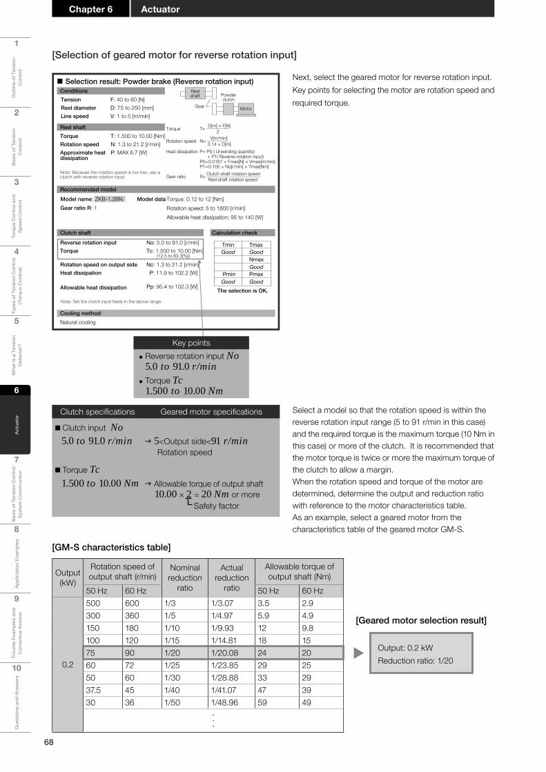
68
1
Out
line
of T
ensi
on
Con
trol
2
Bas
is o
f Ten
sion
C
ontr
ol
3
Torq
ue C
ontr
ol a
nd
Spe
ed C
ontr
ol
4
Type
s of
Ten
sion
Con
trol
(T
orqu
e C
ontr
ol)
5
Wha
t Is
a Te
nsio
n D
etec
tor?
6
Act
uato
r
7
Bas
is o
f Ten
sion
Con
trol
S
yste
m C
onst
ruct
ion
8
App
licat
ion
Exam
ples
9
Trou
ble
Exam
ples
and
C
orre
ctiv
e A
ctio
ns
10
Que
stio
ns a
nd A
nsw
ers
ActuatorChapter 6
Select a model so that the rotation speed is within the reverse rotation input range (5 to 91 r/min in this case) and the required torque is the maximum torque (10 Nm in this case) or more of the clutch. It is recommended that the motor torque is twice or more the maximum torque of the clutch to allow a margin.When the rotation speed and torque of the motor are determined, determine the output and reduction ratio with reference to the motor characteristics table.As an example, select a geared motor from the characteristics table of the geared motor GM-S.
Clutch specifications Geared motor specifications
�Clutch input No 5.0 to 91.0 r/min g 5<Output side<91 r/min
Rotation speed
� Torque Tc 1.500 to 10.00 Nm g Allowable torque of output shaft
10.00 × 2 = 20 Nm or moreSafety factor
Output: 0.2 kWReduction ratio: 1/20
[Gearedmotorselectionresult]
[GM-Scharacteristicstable]
Output (kW)
Rotation speed of output shaft (r/min)
Nominal reduction
ratio
Actualreduction
ratio
Allowable torque of output shaft (Nm)
50 Hz 60 Hz 50 Hz 60 Hz
0.2
500 600 1/3 1/3.07 3.5 2.9300 360 1/5 1/4.97 5.9 4.9150 180 1/10 1/9.93 12 9.8100 120 1/15 1/14.81 18 1575 90 1/20 1/20.08 24 2060 72 1/25 1/23.85 29 2550 60 1/30 1/28.88 33 2937.5 45 1/40 1/41.07 47 3930 36 1/50 1/48.96 59 49
···
[Selectionofgearedmotorforreverserotationinput]
Selection result: Powder brake (Reverse rotation input)Conditions
Reel shaft
Recommended model
Clutch shaft
Cooling method
Calculation check
TensionReel diameterLine speed
Torque
Rotation speed
Gear ratio
Heat dissipation
T= D[m] × F[N]2
Reverse rotation inputTorque
Rotation speed on output sideHeat dissipation
Allowable heat dissipation
TorqueRotation speedApproximate heat dissipation
Natural cooling
The selection is OK.
Tmin Tmax
Nmax
Pmax
Model name: ZKB-1.2BN Model data Torque: 0.12 to 12 [Nm]Rotation speed: 5 to 1800 [r/min]Allowable heat dissipation: 95 to 140 [W]
Gear ratio R: 1
Note: Because the rotation speed is too low, use a clutch with reverse rotation input.
Note: Set the clutch input freely in the above range.
T: 1.500 to 10.00 [Nm]N: 1.3 to 21.2 [r/min]P: MAX 6.7 [W]
No: 5.0 to 91.0 [r/min]Tc: 1.500 to 10.00 [Nm] (12.5 to 83.3[%])
Nc: 1.3 to 21.2 [r/min] P: 11.9 to 102.2 [W]
Pp: 95.4 to 102.3 [W]
F: 40 to 80 [N]D: 75 to 250 [mm]V: 1 to 5 [m/min]
Pmin
R= Clutch shaft rotation speedReel shaft rotation speed
N=
P= P0 ( Unwinding quantity) + P1( Reverse rotation input)
V[m/min]3.14 × D[m]
Powderclutch
MotorGear
Reelshaft
Good
Good
Good
Good
Good
P0= 0.0167 × Fmax[N] × Vmax[m/min]P1= 0.105 × No[r/min] × Tmax[Nm]
Next, select the geared motor for reverse rotation input.Key points for selecting the motor are rotation speed and required torque.
Key points • Reverse rotation input No 5.0 to 91.0 r/min
• Torque Tc 1.500 to 10.00 Nm
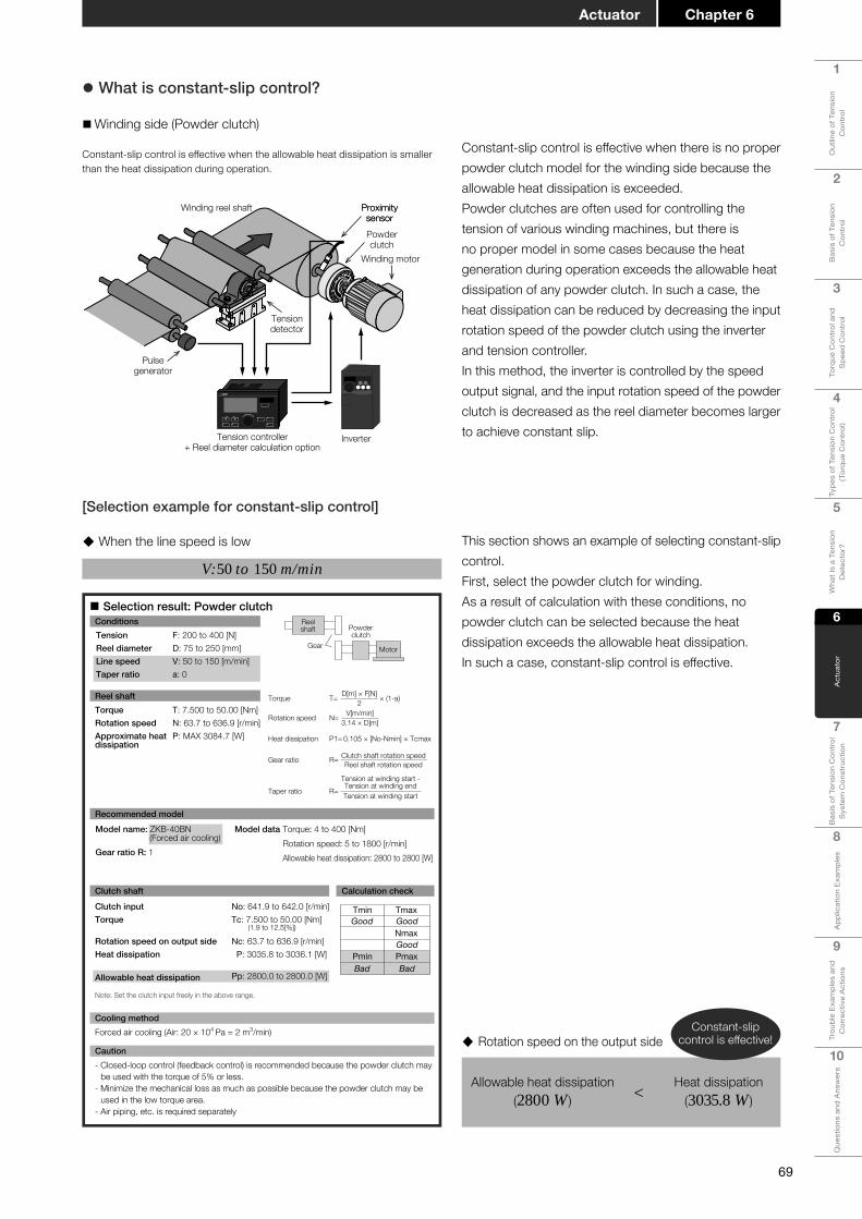
69
1
Out
line
of T
ensi
on
Con
trol
2
Bas
is o
f Ten
sion
C
ontr
ol
3
Torq
ue C
ontr
ol a
nd
Spe
ed C
ontr
ol
4
Type
s of
Ten
sion
Con
trol
(T
orqu
e C
ontr
ol)
5
Wha
t Is
a Te
nsio
n D
etec
tor?
6
Act
uato
r
7
Bas
is o
f Ten
sion
Con
trol
S
yste
m C
onst
ruct
ion
8A
pplic
atio
n Ex
ampl
es
9
Trou
ble
Exam
ples
and
C
orre
ctiv
e A
ctio
ns
10
Que
stio
ns a
nd A
nsw
ers
Chapter 6Actuator
z What is constant-slip control?
�Winding side (Powder clutch)
Constant-slip control is effective when there is no proper powder clutch model for the winding side because the allowable heat dissipation is exceeded.Powder clutches are often used for controlling the tension of various winding machines, but there is no proper model in some cases because the heat generation during operation exceeds the allowable heat dissipation of any powder clutch. In such a case, the heat dissipation can be reduced by decreasing the input rotation speed of the powder clutch using the inverter and tension controller.In this method, the inverter is controlled by the speed output signal, and the input rotation speed of the powder clutch is decreased as the reel diameter becomes larger to achieve constant slip.Tension controller
+ Reel diameter calculation optionInverter
Winding reel shaft Proximitysensor
ProximitysensorPowderclutch
Winding motor
Tensiondetector
Pulsegenerator
Constant-slip control is effective when the allowable heat dissipation is smaller than the heat dissipation during operation.
[Selectionexampleforconstant-slipcontrol]
This section shows an example of selecting constant-slip control.First, select the powder clutch for winding.As a result of calculation with these conditions, no powder clutch can be selected because the heat dissipation exceeds the allowable heat dissipation.In such a case, constant-slip control is effective.
× (1-a)
Selection result: Powder clutchConditions
Reel shaft
Recommended model
Clutch shaft
Cooling method
Calculation check
TensionReel diameterLine speedTaper ratio
Torque
Rotation speed
Gear ratio
Heat dissipation
T= D[m] × F[N]2
Clutch inputTorque
Rotation speed on output sideHeat dissipation
Allowable heat dissipation
TorqueRotation speedApproximate heat dissipation
Forced air cooling (Air: 20 × 104 Pa = 2 m3/min)
Caution- Closed-loop control (feedback control) is recommended because the powder clutch may
be used with the torque of 5% or less.- Minimize the mechanical loss as much as possible because the powder clutch may be
used in the low torque area.- Air piping, etc. is required separately
Model name: ZKB-40BN(Forced air cooling)
Model data Torque: 4 to 400 [Nm]Rotation speed: 5 to 1800 [r/min]Allowable heat dissipation: 2800 to 2800 [W]Gear ratio R: 1
Note: Set the clutch input freely in the above range.
T: 7.500 to 50.00 [Nm]N: 63.7 to 636.9 [r/min]P: MAX 3084.7 [W]
No: 641.9 to 642.0 [r/min]Tc: 7.500 to 50.00 [Nm] (1.9 to 12.5[%])
Nc: 63.7 to 636.9 [r/min] P: 3035.8 to 3036.1 [W]
Pp: 2800.0 to 2800.0 [W]
F: 200 to 400 [N]D: 75 to 250 [mm]V: 50 to 150 [m/min]a: 0
R= Clutch shaft rotation speedReel shaft rotation speed
Taper ratio R=Tension at winding start -Tension at winding endTension at winding start
N=
P1= 0.105 × [No-Nmin] × Tcmax
V[m/min]3.14 × D[m]
Powderclutch
MotorGear
Reelshaft
Tmin Tmax
Nmax
PmaxPmin
Good
Bad
Good
Good
Bad
� When the line speed is low
V:50 to 150 m/min
� Rotation speed on the output side
Allowable heat dissipation (2800 W ) < Heat dissipation
(3035.8 W )
Constant-slip control is effective!

70
1
Out
line
of T
ensi
on
Con
trol
2
Bas
is o
f Ten
sion
C
ontr
ol
3
Torq
ue C
ontr
ol a
nd
Spe
ed C
ontr
ol
4
Type
s of
Ten
sion
Con
trol
(T
orqu
e C
ontr
ol)
5
Wha
t Is
a Te
nsio
n D
etec
tor?
6
Act
uato
r
7
Bas
is o
f Ten
sion
Con
trol
S
yste
m C
onst
ruct
ion
8
App
licat
ion
Exam
ples
9
Trou
ble
Exam
ples
and
C
orre
ctiv
e A
ctio
ns
10
Que
stio
ns a
nd A
nsw
ers
ActuatorChapter 6
<Constant-slip control>Perform the calculation using the same conditions as the previous calculation.In these conditions, the model ZKB-5BN is recommended.
The slection is OK.
Note: Because the heat generation quantity per unit time caused by slip is too large, change the input rotation speed using the inverter, etc. when using the powder clutch.
Dmin DmaxTime
Outputrotation
Input rotationHeat generation quantityper unit time caused by slip whenthe input rotation is not changedHeat generation quantityper unit time caused by slip whenthe input rotation is changed
Powderclutch
Rotationdetector
MotorGear
Reelshaft
Controller Inverter,etc.
× (1-a)
Selection result: Powder clutch (Constant slip)Conditions
Reel shaft
Recommended model
Clutch shaft Calculation check
TensionReel diameterLine speedTaper ratio
Torque
Rotation speed
Gear ratio
Heat dissipation
T= D[m] × F[N]2
Slip rotation speedTorque
Rotation speed on output sideHeat dissipation
Allowable heat dissipation
TorqueRotation speedApproximate heat dissipation
Model name: ZKB-5BN Model data Torque: 0.5 to 50 [Nm]Rotation speed: 5 to 1800 [r/min]Allowable heat dissipation: 180 to 360 [W]
Gear ratio R: 1
Note: Control the input rotation speed so that the slip rotation speed is within the above range.
T: 7.500 to 50.00 [Nm]N: 63.7 to 636.9 [r/min]P: MAX 3084.7 [W]
No: 5.0 to 40.0 [r/min]Tc: 7.500 to 50.00 [Nm] (15.0 to 100.0 [%])
Nc: 63.7 to 636.9 [r/min] P: 26.3 to 210.0 [W]
Pp: 200.6 to 210.8 [W]
F: 200 to 400 [N]D: 75 to 250 [mm]V: 50 to 150 [m/min]a: 0
R= Clutch shaft rotation speedReel shaft rotation speed
Taper ratio R=Tension at winding start -Tension at winding endTension at winding start
N=
P1= 0.105 × [No-Nmin] × Tcmax
V[m/min]3.14 × D[m]
Recommended model
Tmin Tmax
Nmax
PmaxPmin
Good
Good
Good
Good
Good

71
1
Out
line
of T
ensi
on
Con
trol
2
Bas
is o
f Ten
sion
C
ontr
ol
3
Torq
ue C
ontr
ol a
nd
Spe
ed C
ontr
ol
4
Type
s of
Ten
sion
Con
trol
(T
orqu
e C
ontr
ol)
5
Wha
t Is
a Te
nsio
n D
etec
tor?
6
Act
uato
r
7
Bas
is o
f Ten
sion
Con
trol
S
yste
m C
onst
ruct
ion
8A
pplic
atio
n Ex
ampl
es
9
Trou
ble
Exam
ples
and
C
orre
ctiv
e A
ctio
ns
10
Que
stio
ns a
nd A
nsw
ers
Chapter 6Actuator
[Selectionexampleofmotorforconstant-slipcontrol]
Rotation speed and torque
Rotation speed (r/min)
Torq
ue (N
m)
Tension (min)Line speed (min)
Tension (min)Line speed (max)
Tension (max)Line speed (min)
Tension (max)Line speed (max)
25
20
15
10
5
00.0 500.0 1500.01000.0 2000.0 2500.0 3000.0 3500.0
Feasible area
90 r/min (3 Hz)
20
(1) Motor capacity
P = =0.0167×Vmax×Fmax×Dmax
Dmin0.0167×150×400×0.25
0.075 = 3340 W
(2) Winding reel shaft torque
T = =F×D
2(200 to 400)×(0.0750.25)
2 = 7.5 to 50 Nm
(3) Winding reel shaft rotation speed
N = =V
(π×D)(50 to 150)
(3.14×(0.0750.25)) = 63.7 to 637 r/min
(4) Motor shaft rotation speedSuppose that the slip rotation speed of the clutch is 30 r/min
Nm = N + 30 = (63.7 to 637) + 30 = 93.7 to 667 r/min
(5) Temporarily selecting the motorMotor capacity: 3340 W→Rated output: 3.7 kWMotor: SF-HRCA-3.7 K Inverter: FR-E720-3.7 KRated torque: 19.6 Nm (Available torque ratio: 1:50)Rotation speed: 3600 r/min maximum (Rated rotation speed: 1800 r/min) (Available rotation speed ratio: 1:100)
(6) Setting the gear ratio R[1] From the required torque
Rt = =50
19.6
Winding reel shafttorque (max)
Motor rated torque = 2.55 or more shouldbe set.
[2] From the rotation speed setting
Motor rotation speed (max)Motor shaft rotation speed (max)
Rn =3600667 = 5.4 or less should be set.
Rt<R<Rn
2.55<R<5.4→Set R to "3".
(7) Motor shaft torque
T’ = = (7.5 to 50)3
= 2.5 to 16.7 Nm1RT ×
12.8 to 85.2% of the rated torque
(8) Motor shaft rotation speedN' = N×R = (667 to 93.7) × 3 = 281.1 to 2001 r/min 7.8 to 55.6% of the maximum rotation speed
Tension controller+ Reel diameter calculation option
Inverter
Winding reel shaft Proximitysensor
ProximitysensorPowderclutch
Winding motor
Tensiondetector
Pulsegenerator
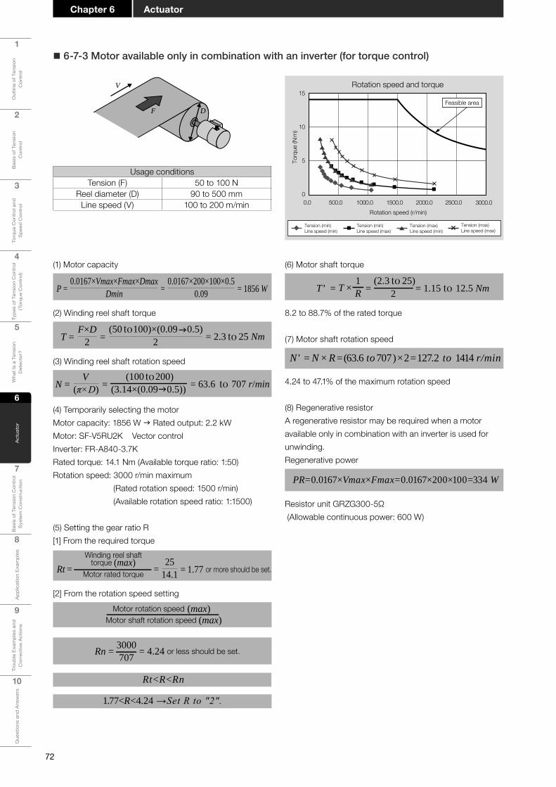
72
1
Out
line
of T
ensi
on
Con
trol
2
Bas
is o
f Ten
sion
C
ontr
ol
3
Torq
ue C
ontr
ol a
nd
Spe
ed C
ontr
ol
4
Type
s of
Ten
sion
Con
trol
(T
orqu
e C
ontr
ol)
5
Wha
t Is
a Te
nsio
n D
etec
tor?
6
Act
uato
r
7
Bas
is o
f Ten
sion
Con
trol
S
yste
m C
onst
ruct
ion
8
App
licat
ion
Exam
ples
9
Trou
ble
Exam
ples
and
C
orre
ctiv
e A
ctio
ns
10
Que
stio
ns a
nd A
nsw
ers
ActuatorChapter 6
� 6-7-3 Motor available only in combination with an inverter (for torque control)
Rotation speed and torque
Rotation speed (r/min)
Torq
ue (N
m)
Tension (min)Line speed (min)
Tension (min)Line speed (max)
Tension (max)Line speed (min)
Tension (max)Line speed (max)
15
10
5
00.0 500.0 1000.0 1500.0 2000.0 2500.0 3000.0
Feasible area
(1) Motor capacity
P = =0.0167×Vmax×Fmax×Dmax
Dmin0.0167×200×100×0.5
0.09 = 1856 W
(2) Winding reel shaft torque
T = =F×D
2(50 to 100)×(0.090.5)
2 = 2.3 to 25 Nm
(3) Winding reel shaft rotation speed
N = =V
(π×D)(100 to200)
(3.14×(0.090.5)) = 63.6 to 707 r/min
(4) Temporarily selecting the motorMotor capacity: 1856 W g Rated output: 2.2 kWMotor: SF-V5RU2K Vector controlInverter: FR-A840-3.7KRated torque: 14.1 Nm (Available torque ratio: 1:50)Rotation speed: 3000 r/min maximum (Rated rotation speed: 1500 r/min) (Available rotation speed ratio: 1:1500)
(5) Setting the gear ratio R[1] From the required torque
Rt = =25
14.1
Winding reel shafttorque (max)
Motor rated torque = 1.77 or more should be set.
[2] From the rotation speed setting
Motor rotation speed (max)Motor shaft rotation speed (max)
Rn = 3000707 = 4.24 or less should be set.
Rt<R<Rn
1.77<R<4.24 →Set R to "2".
(6) Motor shaft torque
T’ = =(2.3 to 25)
2 = 1.15 to 12.5 Nm1RT ×
8.2 to 88.7% of the rated torque
(7) Motor shaft rotation speed
N' = N × R = (63.6 to 707 ) × 2 = 127.2 to 1414 r/min
4.24 to 47.1% of the maximum rotation speed
(8) Regenerative resistorA regenerative resistor may be required when a motor available only in combination with an inverter is used for unwinding.Regenerative power
PR=0.0167×Vmax×Fmax=0.0167×200×100=334 W
Resistor unit GRZG300-5Ω (Allowable continuous power: 600 W)
V
F D
Usage conditionsTension (F) 50 to 100 N
Reel diameter (D) 90 to 500 mmLine speed (V) 100 to 200 m/min

73
1
Out
line
of T
ensi
on
Con
trol
2
Bas
is o
f Ten
sion
C
ontr
ol
3
Torq
ue C
ontr
ol a
nd
Spe
ed C
ontr
ol
4
Type
s of
Ten
sion
Con
trol
(T
orqu
e C
ontr
ol)
5
Wha
t Is
a Te
nsio
n D
etec
tor?
6
Act
uato
r
7
Bas
is o
f Ten
sion
Con
trol
S
yste
m C
onst
ruct
ion
8A
pplic
atio
n Ex
ampl
es
9
Trou
ble
Exam
ples
and
C
orre
ctiv
e A
ctio
ns
10
Que
stio
ns a
nd A
nsw
ers
Chapter 6Actuator
(6) Motor shaft torque
T’ = = (2.3 to 25)2
= 1.15 to 12.5 Nm1RT ×
6.0 to 65.4% of the rated torque
(7) Motor shaft rotation speed
N'=N×R=(63.6 to 707)×2=127 to 1414 r/min
8.4 to 94.2% of the maximum rotation speed
(8) Regenerative resistorA regenerative resistor may be required when a motor available only in combination with an AC servo motor is used for unwinding.Regenerative power
PR=0.0167×Vmax×Fmax=0.0167×200×100=334 W
Regenerative resistor built into the MR-J4-200A: 100 WAccordingly, the external regenerative resistor MR-RB30 (Allowable regenerative power: 300 W) is required.
(1) Motor capacity
P = =0.0167×Vmax×Fmax×Dmax
Dmin0.0167×200×100×0.5
0.09 = 1856 W
(2) Winding reel shaft torque
T = =F×D
2(50 to 100)×(0.090.5)
2 = 2.3 to 25 Nm
(3) Winding reel shaft rotation speed
N = =V
(π×D)(100 to 200)
(3.14×(0.090.5)) = 63.6 to 707 r/min
(4) Temporarily selecting the motorMotor capacity: 1856 W g Rated output: 2.0 kWMotor: HG-SR201amplifier: MR-J4-200ARated torque: 19.1 Nm (Available torque ratio: 1:100)Rotation speed: 1500 r/min maximum (Available rotation speed ratio: 1:1500)
(5) Setting the gear ratio R[1] From the required torque
Rt = =25
19.1
Winding reel shafttorque (max)
Motor rated torque = 1.3 or more should be set.
[2] From the rotation speed settingMotor rotation speed (max)
Motor shaft rotation speed (max)
Rn =1500707 = 2.12 or less should be set.
Rt<R<Rn
1.3<R<2.12→Set R to "2".
� 6-7-4 AC servo motor (for torque control)
Rotation speed (r/min)
Torq
ue (N
m)
Tension (min)Line speed (min)
Tension (min)Line speed (max)
Tension (max)Line speed (min)
Tension (max)Line speed (max)
20
15
10
5
00.0 500.0 1000.0 1500.0
Feasible area
Rotation speed and torqueV
F D
Usage conditionsTension (F) 50 to 100 N
Reel diameter (D) 90 to 500 mmLine speed (V) 100 to 200 m/min

74
1
Out
line
of T
ensi
on
Con
trol
2
Bas
is o
f Ten
sion
C
ontr
ol
3
Torq
ue C
ontr
ol a
nd
Spe
ed C
ontr
ol
4
Type
s of
Ten
sion
Con
trol
(T
orqu
e C
ontr
ol)
5
Wha
t Is
a Te
nsio
n D
etec
tor?
6
Act
uato
r
7
Bas
is o
f Ten
sion
Con
trol
S
yste
m C
onst
ruct
ion
8
App
licat
ion
Exam
ples
9
Trou
ble
Exam
ples
and
C
orre
ctiv
e A
ctio
ns
10
Que
stio
ns a
nd A
nsw
ers
ActuatorChapter 6
� 6-7-5 Motor available only in combination with an inverter (for speed control)
Gear
Motor
Feed motor
[In the case of unwinding]
Winding motor
Gear
Feed motor
[In the case of winding]
Usage conditionsTension (F) 100 to 200 N
Reel diameter (D) 90 to 500 mmLine speed (V) 200 to 300 m/min
Acceleration/deceleration time (t) 20 secMaximum reel shaft inertia moment (l) 15 kgm2
Rotation speed and torque
Rotation speed ( r/min)To
rque
(Nm
)Tension (min)Line speed (min)
Tension (min)Line speed (max)
Tension (max)Line speed (min)
Tension (max)Line speed (max)
50
40
30
20
10
00.0 500.0 1000.0 1500.0 2000.0 2500.0 3000.0
Feasible area
(1) Motor capacity
P = =0.0167×Vmax×Fmax×Dmax
Dmin0.0167×300×200×0.5
0.09 = 5566 W
(2) Required torques[1] Shaft torque
T = =F×D
2(100 to 200)×(0.090.5)
2 = 4.5 to 50 Nm
[2] Torque generated by acceleration/deceleration
T2max = I×α = 15×1 = 15 Nm
Angular acceleration:α angular speed:ω
α = =ωt
(2π×N/60)t =
(2π×191/60)20 = 1 rad/s2
[3] Torque required in the reel shaft
T = T1max+T2max = 50+15 = 65 Nm
(3) Winding reel shaft rotation speed
N = =V
(π×D)(200 to 300)
(3.14×(0.090.5)) = 127 to 1061 r/min
(4) Temporarily selecting the motorMotor capacity: 5566 W g Rated output: 7.5 kWMotor: SF-V5RU7K Inverter: FR-A820-11KRated torque: 47.7 Nm (Available torque ratio: 1:20)Rotation speed: 3000 r/min maximum (Rated rotation speed: 1500 r/min) (Available rotation speed ratio: 1:200)
(5) Setting the gear ratio R[1] From the required torques
Rt = =65
47.7
Winding reel shafttorque (max)
Motor rated torque = 1.36 or more should be set.
[2] From the rotation speed settingMotor rotation speed (max)
Motor shaft rotation speed (max)
Rn =30001061 = 2.82 or less should be set.
Rt < R < Rn
1.36 < R < 2.82 → Set R to "2.5".
(6) Motor shaft torque
T’ = = (4.5 to 65)2.5
= 1.8 to 26 Nm1RT ×
3.7 to 54.5% of the rated torque
(7) Motor shaft rotation speed
N' = N×R = (12 to 1061)×2.5 = 318 to 2653 r/min
10.6 to 88.4% of the maximum rotation speed

75
1
Out
line
of T
ensi
on
Con
trol
2
Bas
is o
f Ten
sion
C
ontr
ol
3
Torq
ue C
ontr
ol a
nd
Spe
ed C
ontr
ol
4
Type
s of
Ten
sion
Con
trol
(T
orqu
e C
ontr
ol)
5
Wha
t Is
a Te
nsio
n D
etec
tor?
6
Act
uato
r
7
Bas
is o
f Ten
sion
Con
trol
S
yste
m C
onst
ruct
ion
8A
pplic
atio
n Ex
ampl
es
9
Trou
ble
Exam
ples
and
C
orre
ctiv
e A
ctio
ns
10
Que
stio
ns a
nd A
nsw
ers
Chapter 6Actuator
� 6-7-6 AC servo motor (for speed control)
(1) Motor capacity
P = =0.0167×Vmax×Fmax×Dmax
Dmin0.0167×300×200×0.5
0.09 = 5566 W
(2) Required torques[1] Shaft torque
T = =F×D
2(100 to 200)×(0.090.5)
2 = 4.5 to 50 Nm
[2] Torque generated by acceleration/deceleration
T2max = I×α = 1.5×1 = 1.5 Nm
Angular acceleration:α angular speed:ω
α = =ωt
(2π×N/60)t =
(2π×191/60)20 = 1 rad/s2
[3] Torque required in the reel shaft
T = T1max+T2max= 50+1.5 = 51.5 Nm(3) Winding reel shaft rotation speed
N = =V
(π×D)(200 to 300)
(3.14×(0.090.5)) = 127 to 1061 r/min
(4) Temporarily selecting the motorMotor capacity: 5566 W g Rated output: 7 kWMotor: HG-SR702Servo amplifier: MR-J4-700ARated torque: 33.4 Nm (Available torque ratio: 1:100)Rotation speed: 3000 r/min maximum (Rated rotation speed: 2000 r/min) (Available rotation speed ratio: 1:50)Motor inertia moment: 154×10-4 kgm2 (0.0154 kgm2)Recommended load inertia moment ratio: 15 times or less
(5) Setting the gear ratio R[1] From the required torques
Rt = =51.533.4
Winding reel shafttorque (max)
Motor rated torque = 1.54 or more should be set.
[2] From the rotation speed settingMotor rotation speed (max)
Motor shaft rotation speed (max)
Rn =30001061 = 2.82 or less should be set.
Rt < R < Rn
1.54 < R < 2.82 → Set R to "2.6". (6) Motor shaft torque
T’ = = (4.5 to 51.5)2.6
= 1.7 to 19.8 Nm1RT ×
5.4 to 66.5% of the rated torque(7) Motor shaft rotation speed
N' = N×R = (127 to 1061)×2.6 = 330 to 2759 r/min
11 to 92% of the maximum rotation speed
(8) Load inertia moment ratio
<R2
Load shaft inertiamoment ratio (Motor inertia moment) x (Load inertia moment ratio)
<1.52.62 0.0154×15
0.221 < 0.231 g OK
Gear
Motor
Feed motor
[In the case of unwinding]
Winding motor
Gear
Feed motor
[In the case of winding]
Rotation speed and torque
Rotation speed (r/min)To
rque
(Nm
)
40
30
20
10
00.0 500.0 1000.0 1500.0 2000.0 2500.0 3000.0
Tension (min)Line speed (min)
Tension (min)Line speed (max)
Tension (max)Line speed (min)
Tension (max)Line speed (max)
Feasible area
Usage conditionsTension (F) 100 to 200 N
Reel diameter (D) 90 to 500 mmLine speed (V) 200 to 300 m/min
Acceleration/deceleration time (t) 20 secMaximum reel shaft inertia moment (l) 15 kgm2

76
1
Out
line
of T
ensi
on
Con
trol
2
Bas
is o
f Ten
sion
C
ontr
ol
3
Torq
ue C
ontr
ol a
nd
Spe
ed C
ontr
ol
4
Type
s of
Ten
sion
Con
trol
(T
orqu
e C
ontr
ol)
5
Wha
t Is
a Te
nsio
n D
etec
tor?
6
Act
uato
r
7
Bas
is o
f Ten
sion
Con
trol
S
yste
m C
onst
ruct
ion
8
App
licat
ion
Exam
ples
9
Trou
ble
Exam
ples
and
C
orre
ctiv
e A
ctio
ns
10
Que
stio
ns a
nd A
nsw
ers
ActuatorChapter 6
Point! When selecting an actuator
First, learn the features of various actuators, identify the machine specifications, and then select a proper actuator. Next, perform detailed calculations for selection, and check whether the temporarily selected actuator meets the intended specifications. It is necessary to examine actuators carefully because selecting a proper actuator has the largest impact on machine performance and economic efficiency.

Chapter 7
Basis of Tension Control System Construction
7-1 Basic tension control system7-2 Configurationofthetensioncontrolsystem7-3 Taper tension control
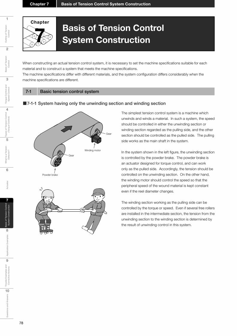
78
1
Out
line
of T
ensi
on
Con
trol
2
Bas
is o
f Ten
sion
C
ontr
ol
3
Torq
ue C
ontr
ol a
nd
Spe
ed C
ontr
ol
4
Type
s of
Ten
sion
Con
trol
(T
orqu
e C
ontr
ol)
5
Wha
t Is
a Te
nsio
n D
etec
tor?
6
Act
uato
r
7
Bas
is o
f Ten
sion
Con
trol
S
yste
m C
onst
ruct
ion
8
App
licat
ion
Exam
ples
9
Trou
ble
Exam
ples
and
C
orre
ctiv
e A
ctio
ns
10
Que
stio
ns a
nd A
nsw
ers
Basis of Tension Control System ConstructionChapter 7
Basis of Tension ControlSystem Construction
Chapter
7
7-1 Basic tension control system
When constructing an actual tension control system, it is necessary to set the machine specifications suitable for each material and to construct a system that meets the machine specifications.The machine specifications differ with different materials, and the system configuration differs considerably when the machine specifications are different.
The simplest tension control system is a machine which unwinds and winds a material. In such a system, the speed should be controlled in either the unwinding section or winding section regarded as the pulling side, and the other section should be controlled as the pulled side. The pulling side works as the main shaft in the system.
In the system shown in the left figure, the unwinding section is controlled by the powder brake. The powder brake is an actuator designed for torque control, and can work only as the pulled side. Accordingly, the tension should be controlled on the unwinding section. On the other hand, the winding motor should control the speed so that the peripheral speed of the wound material is kept constant even if the reel diameter changes.
The winding section working as the pulling side can be controlled by the torque or speed. Even if several free rollers are installed in the intermediate section, the tension from the unwinding section to the winding section is determined by the result of unwinding control in this system.
■7-1-1 System having only the unwinding section and winding section
Winding motor
Powder brake
Gear
Gear
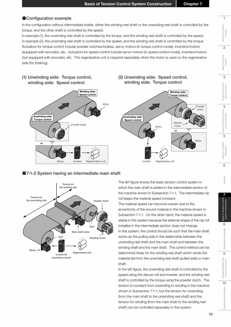
79
1
Out
line
of T
ensi
on
Con
trol
2
Bas
is o
f Ten
sion
C
ontr
ol
3
Torq
ue C
ontr
ol a
nd
Spe
ed C
ontr
ol
4
Type
s of
Ten
sion
Con
trol
(T
orqu
e C
ontr
ol)
5
Wha
t Is
a Te
nsio
n D
etec
tor?
6
Act
uato
r
7
Bas
is o
f Ten
sion
Con
trol
S
yste
m C
onst
ruct
ion
8A
pplic
atio
n Ex
ampl
es
9
Trou
ble
Exam
ples
and
C
orre
ctiv
e A
ctio
ns
10
Que
stio
ns a
nd A
nsw
ers
Chapter 7Basis of Tension Control System Construction
■7-1-2 System having an intermediate main shaft
The left figure shows the basic tension control system in which the main shaft is added in the intermediate section of the machine shown in Subsection 7-1-1. The intermediate nip roll keeps the material speed constant.The material speed can become uneven due to the eccentricity of the wound material in the machine shown in Subsection 7-1-1. On the other hand, the material speed is stable in this system because the external shape of the nip roll installed in the intermediate section does not change.In this system, the control should be such that the main shaft works as the pulling side in the relationship between the unwinding reel shaft and the main shaft and between the winding shaft and the main shaft. The control method can be determined freely for the winding reel shaft which winds the material fed from the unwinding reel shaft (pulled side) or main shaft.In the left figure, the unwinding reel shaft is controlled by the speed using the dancer roll and inverter, and the winding reel shaft is controlled by the torque using the powder clutch. The tension is constant from unwinding to winding in the machine shown in Subsection 7-1-1, but the tension for unwinding (from the main shaft to the unwinding reel shaft) and the tension for winding (from the main shaft to the winding reel shaft) can be controlled separately in this system.
Winding motor
Gear
Gear
Inverter forunwinding control
Regenerative unit Motor
Main shaft motor
Powder clutch
Tension onthe winding side
Tension on the unwinding side
●ConfigurationexampleIn the configuration without intermediate shafts, either the winding reel shaft or the unwinding reel shaft is controlled by the torque, and the other shaft is controlled by the speed.In example (1), the unwinding reel shaft is controlled by the torque, and the winding reel shaft is controlled by the speed. In example (2), the unwinding reel shaft is controlled by the speed, and the winding reel shaft is controlled by the torque. Actuators for torque control include powder clutches/brakes, servo motors (in torque control mode), inverters/motors (equipped with encoder), etc. Actuators for speed control include servo motors (in speed control mode), inverters/motors (not equipped with encoder), etc. The regenerative unit is required separately when the motor is used on the regenerative side (for braking).
(2) Unwinding side: Speed control, winding side: Torque control
(1) Unwinding side: Torque control, winding side: Speed control
Powder brake
Motor
Motor Inverter Regenerative unit
or
Unwinding side:Torque control
Winding side:Speed control
orMotor
Motor
Inverter Regenerative unit
Unwinding side:Speed control
Winding side:Torque control
Gearedmotor
Powderclutch
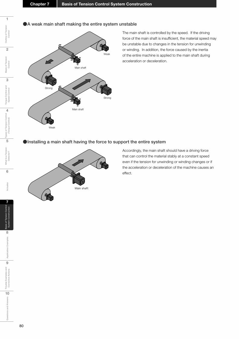
80
1
Out
line
of T
ensi
on
Con
trol
2
Bas
is o
f Ten
sion
C
ontr
ol
3
Torq
ue C
ontr
ol a
nd
Spe
ed C
ontr
ol
4
Type
s of
Ten
sion
Con
trol
(T
orqu
e C
ontr
ol)
5
Wha
t Is
a Te
nsio
n D
etec
tor?
6
Act
uato
r
7
Bas
is o
f Ten
sion
Con
trol
S
yste
m C
onst
ruct
ion
8
App
licat
ion
Exam
ples
9
Trou
ble
Exam
ples
and
C
orre
ctiv
e A
ctio
ns
10
Que
stio
ns a
nd A
nsw
ers
Basis of Tension Control System ConstructionChapter 7
The main shaft is controlled by the speed. If the driving force of the main shaft is insufficient, the material speed may be unstable due to changes in the tension for unwinding or winding. In addition, the force caused by the inertia of the entire machine is applied to the main shaft during acceleration or deceleration.
Main shaft
Weak
Strong
Main shaft
Weak
Strong
●A weak main shaft making the entire system unstable
Accordingly, the main shaft should have a driving force that can control the material stably at a constant speed even if the tension for unwinding or winding changes or if the acceleration or deceleration of the machine causes an effect.
Main shaft
●Installing a main shaft having the force to support the entire system
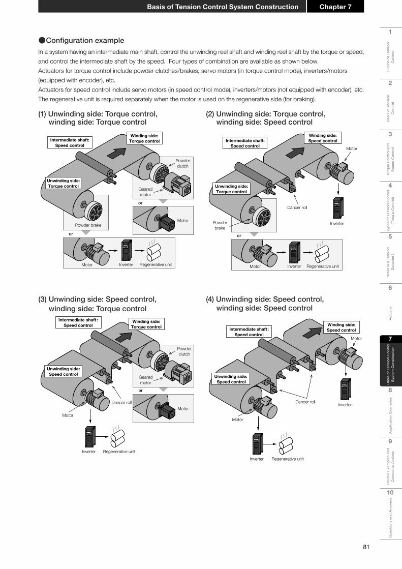
81
1
Out
line
of T
ensi
on
Con
trol
2
Bas
is o
f Ten
sion
C
ontr
ol
3
Torq
ue C
ontr
ol a
nd
Spe
ed C
ontr
ol
4
Type
s of
Ten
sion
Con
trol
(T
orqu
e C
ontr
ol)
5
Wha
t Is
a Te
nsio
n D
etec
tor?
6
Act
uato
r
7
Bas
is o
f Ten
sion
Con
trol
S
yste
m C
onst
ruct
ion
8A
pplic
atio
n Ex
ampl
es
9
Trou
ble
Exam
ples
and
C
orre
ctiv
e A
ctio
ns
10
Que
stio
ns a
nd A
nsw
ers
Chapter 7Basis of Tension Control System Construction
●ConfigurationexampleIn a system having an intermediate main shaft, control the unwinding reel shaft and winding reel shaft by the torque or speed, and control the intermediate shaft by the speed. Four types of combination are available as shown below. Actuators for torque control include powder clutches/brakes, servo motors (in torque control mode), inverters/motors (equipped with encoder), etc. Actuators for speed control include servo motors (in speed control mode), inverters/motors (not equipped with encoder), etc. The regenerative unit is required separately when the motor is used on the regenerative side (for braking).
(4) Unwinding side: Speed control, winding side: Speed control
(2) Unwinding side: Torque control, winding side: Speed control
(3) Unwinding side: Speed control, winding side: Torque control
(1) Unwinding side: Torque control, winding side: Torque control
or
Unwinding side:Torque control
Winding side:Speed controlIntermediate shaft:
Speed control Motor
Dancer roll
Powderbrake
Inverter
Motor Inverter Regenerative unitMotor Inverter Regenerative unit
or
Unwinding side:Torque control
Winding side:Torque controlIntermediate shaft:
Speed control
Powder brake
or
Motor
Gearedmotor
Powderclutch
Winding side:Torque control
or
Motor
Gearedmotor
Powderclutch
Dancer roll
Motor
Inverter Regenerative unit
Unwinding side:Speed control
Intermediate shaft :Speed control
Unwinding side: Speed control
Winding side:Speed controlIntermediate shaft:
Speed control
Dancer roll
Motor
Inverter Regenerative unit
Motor
Inverter
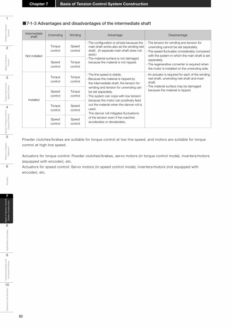
82
1
Out
line
of T
ensi
on
Con
trol
2
Bas
is o
f Ten
sion
C
ontr
ol
3
Torq
ue C
ontr
ol a
nd
Spe
ed C
ontr
ol
4
Type
s of
Ten
sion
Con
trol
(T
orqu
e C
ontr
ol)
5
Wha
t Is
a Te
nsio
n D
etec
tor?
6
Act
uato
r
7
Bas
is o
f Ten
sion
Con
trol
S
yste
m C
onst
ruct
ion
8
App
licat
ion
Exam
ples
9
Trou
ble
Exam
ples
and
C
orre
ctiv
e A
ctio
ns
10
Que
stio
ns a
nd A
nsw
ers
Basis of Tension Control System ConstructionChapter 7
■7-1-3 Advantages and disadvantages of the intermediate shaft
Intermediate shaft Unwinding Winding Advantage Disadvantage
Not installed
Torque control
Speed control
- The configuration is simple because the main shaft works also as the winding reel shaft. (A separate main shaft does not exist.)
- The material surface is not damaged because the material is not nipped.
- The tension for winding and tension for unwinding cannot be set separately.
- The speed fluctuates considerably compared with the system in which the main shaft is set separately.
- The regenerative converter is required when the motor is installed on the unwinding side.
Speed control
Torque control
Installed
Torque control
Torque control
- The line speed is stable.- Because the material is nipped by
the intermediate shaft, the tension for winding and tension for unwinding can be set separately.
- The system can cope with low tension because the motor can positively feed out the material when the dancer roll is used.The dancer roll mitigates fluctuations of the tension even if the machine accelerates or decelerates.
- An actuator is required for each of the winding reel shaft, unwinding reel shaft and main shaft.
- The material surface may be damaged because the material is nipped.Speed
controlTorque control
Torque control
Speed control
Speed control
Speed control
Powder clutches/brakes are suitable for torque control at low line speed, and motors are suitable for torque control at high line speed.
Actuators for torque control: Powder clutches/brakes, servo motors (in torque control mode), inverters/motors (equipped with encoder), etc. Actuators for speed control: Servo motors (in speed control mode), inverters/motors (not equipped with encoder), etc.
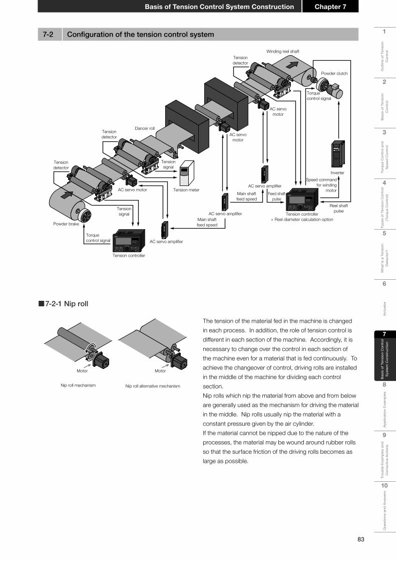
83
1
Out
line
of T
ensi
on
Con
trol
2
Bas
is o
f Ten
sion
C
ontr
ol
3
Torq
ue C
ontr
ol a
nd
Spe
ed C
ontr
ol
4
Type
s of
Ten
sion
Con
trol
(T
orqu
e C
ontr
ol)
5
Wha
t Is
a Te
nsio
n D
etec
tor?
6
Act
uato
r
7
Bas
is o
f Ten
sion
Con
trol
S
yste
m C
onst
ruct
ion
8A
pplic
atio
n Ex
ampl
es
9
Trou
ble
Exam
ples
and
C
orre
ctiv
e A
ctio
ns
10
Que
stio
ns a
nd A
nsw
ers
Chapter 7Basis of Tension Control System Construction
7-2 Configurationofthetensioncontrolsystem
AC servomotor
AC servomotor
AC servo motorFeed shaft
pulse
Tension controller+ Reel diameter calculation option
Reel shaftpulse
Main shaftfeed speed
Main shaftfeed speed
Tension meter
Tensiondetector
Tensiondetector
Tensiondetector
Winding reel shaft
Torquecontrol signal
Tensionsignal
Tensionsignal
Dancer roll
Speed commandfor winding
motor
Inverter
Powder clutch
Torquecontrol signal
AC servo amplifier
Tension controller
AC servo amplifier
AC servo amplifier
Powder brake
The tension of the material fed in the machine is changed in each process. In addition, the role of tension control is different in each section of the machine. Accordingly, it is necessary to change over the control in each section of the machine even for a material that is fed continuously. To achieve the changeover of control, driving rolls are installed in the middle of the machine for dividing each control section. Nip rolls which nip the material from above and from below are generally used as the mechanism for driving the material in the middle. Nip rolls usually nip the material with a constant pressure given by the air cylinder.If the material cannot be nipped due to the nature of the processes, the material may be wound around rubber rolls so that the surface friction of the driving rolls becomes as large as possible.
Motor
Nip roll mechanism Nip roll alternative mechanism
Motor
■7-2-1 Nip roll

84
1
Out
line
of T
ensi
on
Con
trol
2
Bas
is o
f Ten
sion
C
ontr
ol
3
Torq
ue C
ontr
ol a
nd
Spe
ed C
ontr
ol
4
Type
s of
Ten
sion
Con
trol
(T
orqu
e C
ontr
ol)
5
Wha
t Is
a Te
nsio
n D
etec
tor?
6
Act
uato
r
7
Bas
is o
f Ten
sion
Con
trol
S
yste
m C
onst
ruct
ion
8
App
licat
ion
Exam
ples
9
Trou
ble
Exam
ples
and
C
orre
ctiv
e A
ctio
ns
10
Que
stio
ns a
nd A
nsw
ers
Basis of Tension Control System ConstructionChapter 7
It is essential that the machine has only one main shaft and that its speed is controlled. The main shaft determines the processing speed of the entire machine, and other driving shafts should follow the main shaft to feed the web stably.The main shaft works as the leader of the entire machine. In the same way that a human leader should exert leadership to control, conduct and lead a group, the main shaft should have sufficient force to lead the entire machine properly. The term "force" here refers to sufficiently stable speed control and torque.The material is affected by three types of forces (torques): "force of the tension", "force caused by the inertia" and "force caused by mechanical friction". The main shaft should rotate stably even if these forces change successively. Especially when the machine accelerates or decelerates, the torque caused by the inertia of all rotating parts of the machine is applied to the main shaft. This fact should be considered when selecting the actuator for the main shaft.
■7-2-2 Setting the main shaft
■7-2-3 Tension control method
Main shaft
[Unwinding control]
Unwinding control is performed in the area from the reel from which the material is unwound to the first driving roll. Unwinding control is required to unwind the material whose diameter changes at a constant tension. In unwinding control, the driving roll should work as the pulling side and the unwinding reel shaft should work as the pulled side.In some machines including resin film forming machines, the unwinding section does not exist because resin is fed out continuously in a film shape.
[1-shaft unwinding mechanism]
The brake is installed in the reel shaft. Because of the relationship "Unwinding tension = Braking torque/Unwinding radius", a constant tension can be achieved when the braking torque is decreased in accordance with the decrease of the reel diameter.A speed increaser and speed reducer such as gear and pulley are installed as necessary between the reel shaft and the brake.
AC servomotor
Tension detector
Tensionsignal
Torque controlsignal
Powder brake
Tension controller
AC servoamplifier
●Unwinding mechanism
Brake
Feed motor
Radius
Tension

85
1
Out
line
of T
ensi
on
Con
trol
2
Bas
is o
f Ten
sion
C
ontr
ol
3
Torq
ue C
ontr
ol a
nd
Spe
ed C
ontr
ol
4
Type
s of
Ten
sion
Con
trol
(T
orqu
e C
ontr
ol)
5
Wha
t Is
a Te
nsio
n D
etec
tor?
6
Act
uato
r
7
Bas
is o
f Ten
sion
Con
trol
S
yste
m C
onst
ruct
ion
8A
pplic
atio
n Ex
ampl
es
9
Trou
ble
Exam
ples
and
C
orre
ctiv
e A
ctio
ns
10
Que
stio
ns a
nd A
nsw
ers
Chapter 7Basis of Tension Control System Construction
[Simultaneous multi-shaft unwinding mechanism]
In the single cutter (overlapped paper cutting machine), yarn sizing machine and film laminator, long materials wound around multiple reels are unwound at the same time. When overall tension control is performed, the torque of each brake should be even. The intended tension (tension set value) is changed in accordance with the thickness, width, strength, etc. of the material. In addition, because the reel diameter is always changing, each brake should have sufficient performance to adjust the torque in a wide range.
[Unwinding mechanism with motor]
Positive unwinding mechanismIn the following cases, the reel shaft may be driven by the motor to achieve positive unwinding:
• When the reel is heavy, and manual operations such as initial paper passing should be made easy
• When the peripheral speed of the preparatory reel should be controlled so that it becomes equivalent to the unwinding speed of the currently used reel in the automatic paper splicing device (auto paster)
• When the tension caused by mechanical loss of the unwinding shaft is high compared with the intended unwinding tension
• When the acceleration tension caused by the reel inertia is high at startup (Positive unwinding and compensation of the mechanical loss or inertia are required.)
In the above cases, tension control by the speed using the dancer roll mechanism is generally required.
Unwinding mechanism driven by reverse rotation
In the following cases, the motor and clutch are used instead of the brake to drive the reel by reverse rotation:
• When the material is wound and unwound between a pair of reels in the rewinding machine
• When the rotation speed of the brake is 5 r/min (15 r/min in the ZA type) or less on the unwinding side
Brake
Feed motor
BrakeBrake
Feed motor
Clutch
Geared motor
Dancer roll
Feed motor
Feed motor
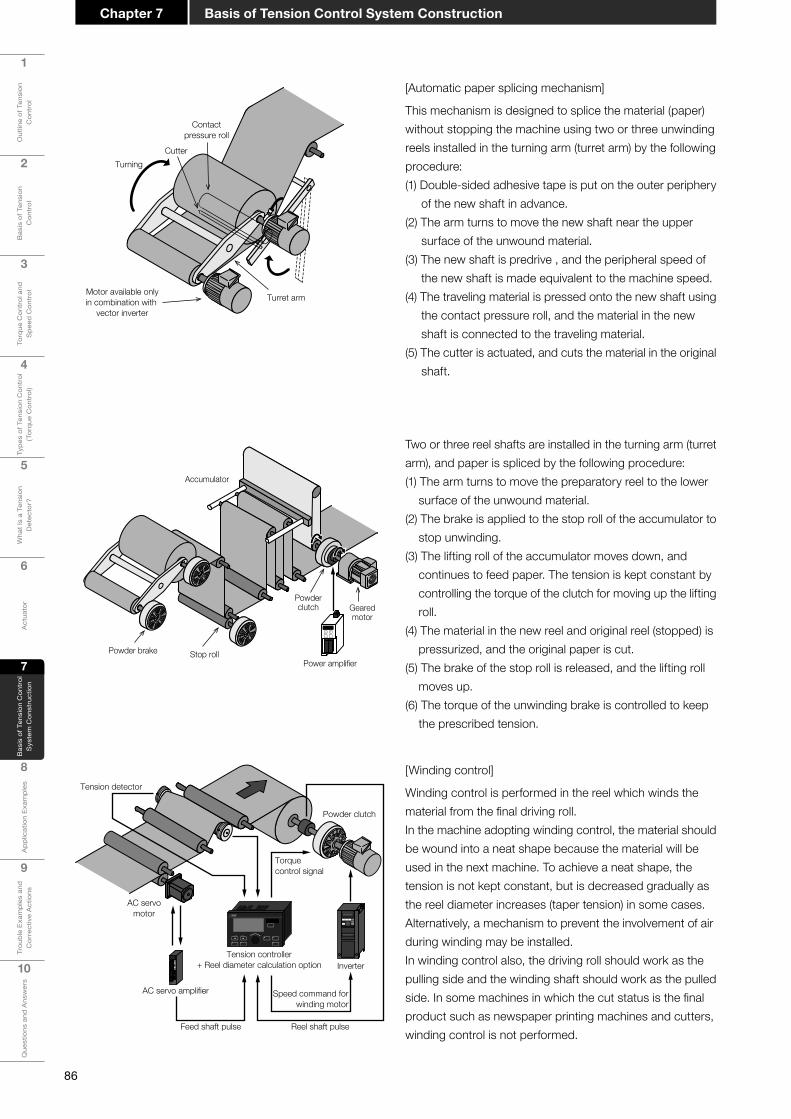
86
1
Out
line
of T
ensi
on
Con
trol
2
Bas
is o
f Ten
sion
C
ontr
ol
3
Torq
ue C
ontr
ol a
nd
Spe
ed C
ontr
ol
4
Type
s of
Ten
sion
Con
trol
(T
orqu
e C
ontr
ol)
5
Wha
t Is
a Te
nsio
n D
etec
tor?
6
Act
uato
r
7
Bas
is o
f Ten
sion
Con
trol
S
yste
m C
onst
ruct
ion
8
App
licat
ion
Exam
ples
9
Trou
ble
Exam
ples
and
C
orre
ctiv
e A
ctio
ns
10
Que
stio
ns a
nd A
nsw
ers
Basis of Tension Control System ConstructionChapter 7
[Winding control]
Winding control is performed in the reel which winds the material from the final driving roll.In the machine adopting winding control, the material should be wound into a neat shape because the material will be used in the next machine. To achieve a neat shape, the tension is not kept constant, but is decreased gradually as the reel diameter increases (taper tension) in some cases. Alternatively, a mechanism to prevent the involvement of air during winding may be installed.In winding control also, the driving roll should work as the pulling side and the winding shaft should work as the pulled side. In some machines in which the cut status is the final product such as newspaper printing machines and cutters, winding control is not performed.
Tension detector
AC servomotor
Feed shaft pulse Reel shaft pulse
Speed command forwinding motor
Torque control signal
Tension controller+ Reel diameter calculation option
AC servo amplifier
Inverter
Powder clutch
[Automatic paper splicing mechanism]
This mechanism is designed to splice the material (paper) without stopping the machine using two or three unwinding reels installed in the turning arm (turret arm) by the following procedure:(1) Double-sided adhesive tape is put on the outer periphery
of the new shaft in advance.(2) The arm turns to move the new shaft near the upper
surface of the unwound material.(3) The new shaft is predrive , and the peripheral speed of
the new shaft is made equivalent to the machine speed.(4) The traveling material is pressed onto the new shaft using
the contact pressure roll, and the material in the new shaft is connected to the traveling material.
(5) The cutter is actuated, and cuts the material in the original shaft.
Two or three reel shafts are installed in the turning arm (turret arm), and paper is spliced by the following procedure:(1) The arm turns to move the preparatory reel to the lower
surface of the unwound material.(2) The brake is applied to the stop roll of the accumulator to
stop unwinding.(3) The lifting roll of the accumulator moves down, and
continues to feed paper. The tension is kept constant by controlling the torque of the clutch for moving up the lifting roll.
(4) The material in the new reel and original reel (stopped) is pressurized, and the original paper is cut.
(5) The brake of the stop roll is released, and the lifting roll moves up.
(6) The torque of the unwinding brake is controlled to keep the prescribed tension.
Motor available onlyin combination with
vector inverter
Turning
Turret arm
Contactpressure roll
Cutter
Powderclutch Geared
motor
Power amplifier
Accumulator
Stop rollPowder brake
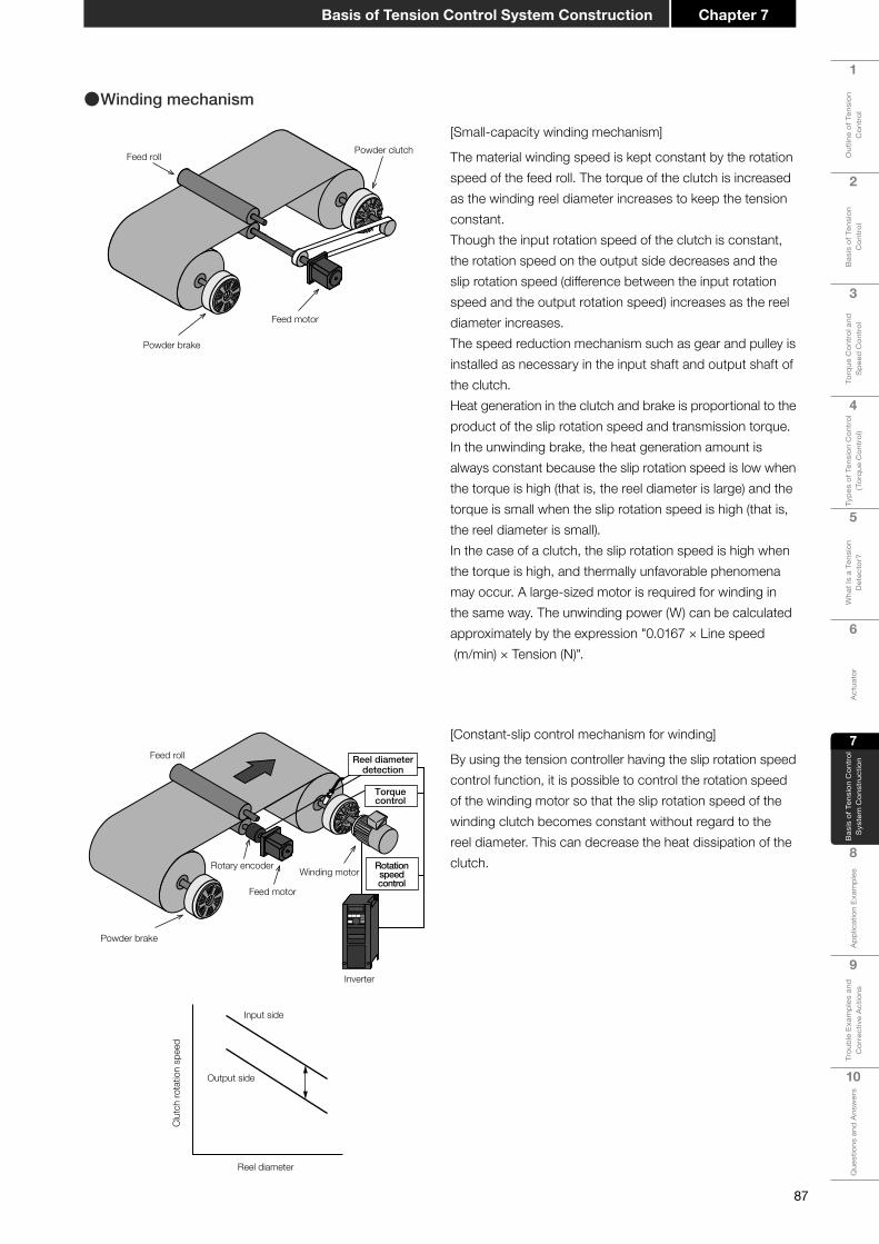
87
1
Out
line
of T
ensi
on
Con
trol
2
Bas
is o
f Ten
sion
C
ontr
ol
3
Torq
ue C
ontr
ol a
nd
Spe
ed C
ontr
ol
4
Type
s of
Ten
sion
Con
trol
(T
orqu
e C
ontr
ol)
5
Wha
t Is
a Te
nsio
n D
etec
tor?
6
Act
uato
r
7
Bas
is o
f Ten
sion
Con
trol
S
yste
m C
onst
ruct
ion
8A
pplic
atio
n Ex
ampl
es
9
Trou
ble
Exam
ples
and
C
orre
ctiv
e A
ctio
ns
10
Que
stio
ns a
nd A
nsw
ers
Chapter 7Basis of Tension Control System Construction
[Small-capacity winding mechanism]
The material winding speed is kept constant by the rotation speed of the feed roll. The torque of the clutch is increased as the winding reel diameter increases to keep the tension constant.Though the input rotation speed of the clutch is constant, the rotation speed on the output side decreases and the slip rotation speed (difference between the input rotation speed and the output rotation speed) increases as the reel diameter increases.The speed reduction mechanism such as gear and pulley is installed as necessary in the input shaft and output shaft of the clutch.Heat generation in the clutch and brake is proportional to the product of the slip rotation speed and transmission torque. In the unwinding brake, the heat generation amount is always constant because the slip rotation speed is low when the torque is high (that is, the reel diameter is large) and the torque is small when the slip rotation speed is high (that is, the reel diameter is small).In the case of a clutch, the slip rotation speed is high when the torque is high, and thermally unfavorable phenomena may occur. A large-sized motor is required for winding in the same way. The unwinding power (W) can be calculated approximately by the expression "0.0167 × Line speed (m/min) × Tension (N)".
●Winding mechanism
Powder brake
Feed motor
Feed rollPowder clutch
[Constant-slip control mechanism for winding]
By using the tension controller having the slip rotation speed control function, it is possible to control the rotation speed of the winding motor so that the slip rotation speed of the winding clutch becomes constant without regard to the reel diameter. This can decrease the heat dissipation of the clutch.
Powder brake
Feed motor
Feed roll
Winding motorRotary encoder
Inverter
Reel diameterdetection
Torquecontrol
Rotationspeedcontrol
Reel diameter
Clut
ch ro
tatio
n sp
eed
Input side
Output side

88
1
Out
line
of T
ensi
on
Con
trol
2
Bas
is o
f Ten
sion
C
ontr
ol
3
Torq
ue C
ontr
ol a
nd
Spe
ed C
ontr
ol
4
Type
s of
Ten
sion
Con
trol
(T
orqu
e C
ontr
ol)
5
Wha
t Is
a Te
nsio
n D
etec
tor?
6
Act
uato
r
7
Bas
is o
f Ten
sion
Con
trol
S
yste
m C
onst
ruct
ion
8
App
licat
ion
Exam
ples
9
Trou
ble
Exam
ples
and
C
orre
ctiv
e A
ctio
ns
10
Que
stio
ns a
nd A
nsw
ers
Basis of Tension Control System ConstructionChapter 7
[Multi-shaft winding mechanism]
In the slitter (which cuts a wide sheet into tape) and separator (which separates a laminated sheet and winds it), the clutches may be installed in multiple reel shafts and controlled by one winding motor as shown in the left figure.
[Continuous winding mechanism]
When both automatic paper splicing & unwinding and automatic paper splicing & winding are performed at the same time, an accumulator is installed (for paper splicing while winding is stopped) in some cases and is not installed (for paper splicing while winding is performed) in other cases.When an accumulator is not installed, predrive control is required to match the peripheral speed. The left figure shows the 2-shaft winding mechanism in which out-feed control is adopted in the continuous winding method (without the accumulator).In the winding mechanism, the clutch and motor are installed in the turret arm in some cases, and installed on the stationary side in other cases.
[Surface winding]
The area around the reel shaft is in contact with the under-roll by the pressure from the press roll.The clutch controls the under-roll driving torque to achieve a constant tension.
Winding motor
Powder clutch
Feed motor
Winding motor
Feed motor
Tension detector
Powder clutch
Turret armTurning
Out-feed roll
Powder brakePowder clutch
Feed motor
Press rollFeed roll
Under-roll
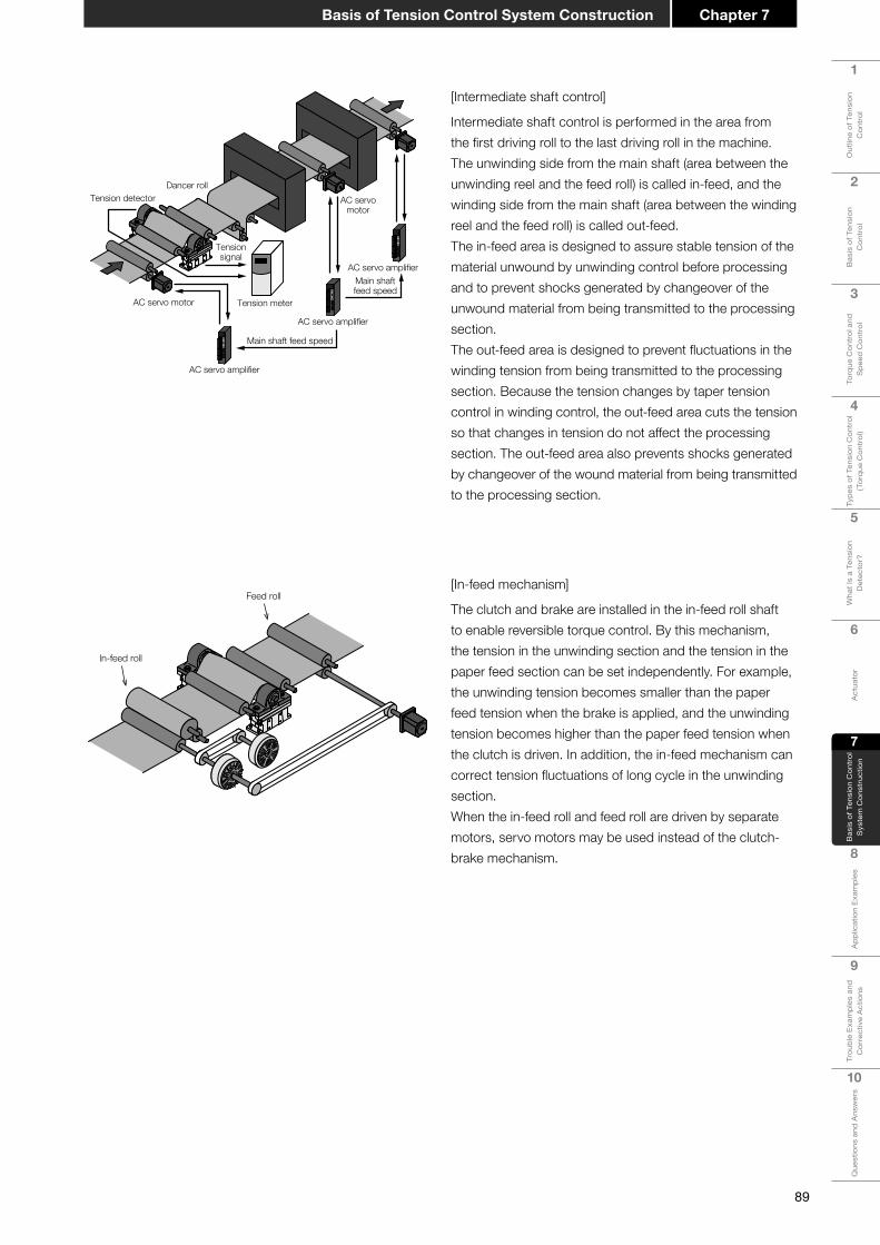
89
1
Out
line
of T
ensi
on
Con
trol
2
Bas
is o
f Ten
sion
C
ontr
ol
3
Torq
ue C
ontr
ol a
nd
Spe
ed C
ontr
ol
4
Type
s of
Ten
sion
Con
trol
(T
orqu
e C
ontr
ol)
5
Wha
t Is
a Te
nsio
n D
etec
tor?
6
Act
uato
r
7
Bas
is o
f Ten
sion
Con
trol
S
yste
m C
onst
ruct
ion
8A
pplic
atio
n Ex
ampl
es
9
Trou
ble
Exam
ples
and
C
orre
ctiv
e A
ctio
ns
10
Que
stio
ns a
nd A
nsw
ers
Chapter 7Basis of Tension Control System Construction
[Intermediate shaft control]
Intermediate shaft control is performed in the area from the first driving roll to the last driving roll in the machine. The unwinding side from the main shaft (area between the unwinding reel and the feed roll) is called in-feed, and the winding side from the main shaft (area between the winding reel and the feed roll) is called out-feed.The in-feed area is designed to assure stable tension of the material unwound by unwinding control before processing and to prevent shocks generated by changeover of the unwound material from being transmitted to the processing section.The out-feed area is designed to prevent fluctuations in the winding tension from being transmitted to the processing section. Because the tension changes by taper tension control in winding control, the out-feed area cuts the tension so that changes in tension do not affect the processing section. The out-feed area also prevents shocks generated by changeover of the wound material from being transmitted to the processing section.
AC servomotor
AC servo motor
Main shaft feed speed
Main shaftfeed speed
Tension meter
Tension detector
Tensionsignal
Dancer roll
AC servo amplifier
AC servo amplifier
AC servo amplifier
[In-feed mechanism]
The clutch and brake are installed in the in-feed roll shaft to enable reversible torque control. By this mechanism, the tension in the unwinding section and the tension in the paper feed section can be set independently. For example, the unwinding tension becomes smaller than the paper feed tension when the brake is applied, and the unwinding tension becomes higher than the paper feed tension when the clutch is driven. In addition, the in-feed mechanism can correct tension fluctuations of long cycle in the unwinding section.When the in-feed roll and feed roll are driven by separate motors, servo motors may be used instead of the clutch-brake mechanism.
In-feed roll
Feed roll

90
1
Out
line
of T
ensi
on
Con
trol
2
Bas
is o
f Ten
sion
C
ontr
ol
3
Torq
ue C
ontr
ol a
nd
Spe
ed C
ontr
ol
4
Type
s of
Ten
sion
Con
trol
(T
orqu
e C
ontr
ol)
5
Wha
t Is
a Te
nsio
n D
etec
tor?
6
Act
uato
r
7
Bas
is o
f Ten
sion
Con
trol
S
yste
m C
onst
ruct
ion
8
App
licat
ion
Exam
ples
9
Trou
ble
Exam
ples
and
C
orre
ctiv
e A
ctio
ns
10
Que
stio
ns a
nd A
nsw
ers
Basis of Tension Control System ConstructionChapter 7
Point! Construction of the tension control system
• Determining the main shaft in the machine used as the reference of the speed
• Dividing control sections, and installing nip rolls
• Determining the control type (speed control or torque control) to be adopted in each control section
• Determining the control method (dancer roll or tension detector)
7-3 Taper tension control
Constant tension control
Taper tension control
Reel diameter mmφ
Cont
rolle
d te
nsio
n N
OMinimumdiameter
Maximumdiameter
Taperratio
Taper tension control (taper control) refers to the control which changes the tension in accordance with changes in the reel diameter.Taper control is mainly used for winding control. The tension is decreased as the reel diameter increases so that the material is not wound too tightly or not displaced during winding.The taper ratio refers to the inclination of tension decrease against constant tension control as shown in the left figure.
●Taper tension control
●Broken line taper tension control
Constant tension control
Broken line taper tension control
Reel diameter mmφ
Cont
rolle
d te
nsio
n N
T1
T2
T3
C1
OMinimumdiameter
Maximumdiameter
C2 C3 C4
T4
Broken line taper tension control refers to taper tension control which changes the taper ratio in the intermediate reel diameter without using the same taper ratio from the initial diameter to the final diameter.

Chapter 8
Application Examples
8-1 Business form printing machine8-2 Offsetprintingmachine8-3 Gravure printing machine8-4 Screen printing machine8-5 Unwinder8-6 Punching machine8-7 Inflatableextruder+2-shaftfilmwinder8-8 Multiple cutter8-9 Slitter (1)8-10 Laminator8-11 Rolling machine8-12 Film cleaning machine8-13 Plating machine8-14 Winder8-15 Thickness measuring instrument8-16 Steel plate plating line8-17 Static electricity eliminating device8-18 Slitter (2)8-19 Laminator8-20 Film processing machine

92
1
Out
line
of T
ensi
on
Con
trol
2
Bas
is o
f Ten
sion
C
ontr
ol
3
Torq
ue C
ontr
ol a
nd
Spe
ed C
ontr
ol
4
Type
s of
Ten
sion
Con
trol
(T
orqu
e C
ontr
ol)
5
Wha
t Is
a Te
nsio
n D
etec
tor?
6
Act
uato
r
7
Bas
is o
f Ten
sion
Con
trol
S
yste
m C
onst
ruct
ion
8
App
licat
ion
Exam
ples
9
Trou
ble
Exam
ples
and
C
orre
ctiv
e A
ctio
ns
10
Que
stio
ns a
nd A
nsw
ers
Application ExamplesChapter 8
Features
Usage conditions
Applicable models
Powder brakeZKB-5HBN
Tension controllerLE7-40GU-L
Unwinding
Printing section
Tensiondetector
LX-050TD
• The feedback type tension controller is used to prevent color shift in printing and improve the pitch accuracy of punched holes used for feed to the printer.
• The stall memory function is effective in the inching operation for color matching during printing to reduce color shift and pitch deviation at restart.
• When the machine decelerates immediately before the base paper runs short, the deceleration gain is utilized to reduce color shift and pitch deviation caused by slackness.
• The powder brake is the thermo block cooling type which does not require water piping.
Unwinding
Tension N 100 to 200
Line speed m/min 250 or less
Reel diameter φ 95 to 800
Powder brake ZKB-5HBNTension controller LE7-40GU-LTension detector LX-050TD
Workpiece material Printer paper
8-1 Business form printing machine

93
1
Out
line
of T
ensi
on
Con
trol
2
Bas
is o
f Ten
sion
C
ontr
ol
3
Torq
ue C
ontr
ol a
nd
Spe
ed C
ontr
ol
4
Type
s of
Ten
sion
Con
trol
(T
orqu
e C
ontr
ol)
5
Wha
t Is
a Te
nsio
n D
etec
tor?
6
Act
uato
r
7
Bas
is o
f Ten
sion
Con
trol
S
yste
m C
onst
ruct
ion
8A
pplic
atio
n Ex
ampl
es
9
Trou
ble
Exam
ples
and
C
orre
ctiv
e A
ctio
ns
10
Que
stio
ns a
nd A
nsw
ers
Chapter 8Application Examples
Features
Usage conditions
Applicable models
To processingsection
Regenerativeunit
Proximityswitch
MotorSF-V5RU37K
InverterFR-A820-55K
+FR-A8AP
Regenerativeunit
LD-10WTB-CCL
Tension detectorLX-050TD
Rotary encoder
LD-10WTB-DCA
LM-10WA-TAD
Tensioncontroller
• Fully-automatic paper splicing (auto paster) may be performed in the paper feed section to save labor.
• In tension control, the reel diameter is detected and fed back for automatic paper splicing.
• The stall memory function is effective in the inching operation for color matching during printing to reduce color shift and pitch deviation at restart.
• When the machine decelerates immediately before the base paper runs short, the deceleration gain is utilized to reduce color shift and pitch deviation caused by slackness.
Unwinding
Tension N 200 to 300
Line speed m/min 500 or less
Reel diameter φ 100 to 1000
Vector inverter FR-A820-55K + FR-A8AP (option)Motor SF-V5RU37K
Tension controller LD-10WTB-CCL + LD-10WTB-DCA + LM-10WA-TAD or LE-10WTA-CCL + LD-10WTB-DCA x 2 units
Tension detector LX-050TD
8-2 Offsetprintingmachine

94
1
Out
line
of T
ensi
on
Con
trol
2
Bas
is o
f Ten
sion
C
ontr
ol
3
Torq
ue C
ontr
ol a
nd
Spe
ed C
ontr
ol
4
Type
s of
Ten
sion
Con
trol
(T
orqu
e C
ontr
ol)
5
Wha
t Is
a Te
nsio
n D
etec
tor?
6
Act
uato
r
7
Bas
is o
f Ten
sion
Con
trol
S
yste
m C
onst
ruct
ion
8
App
licat
ion
Exam
ples
9
Trou
ble
Exam
ples
and
C
orre
ctiv
e A
ctio
ns
10
Que
stio
ns a
nd A
nsw
ers
Application ExamplesChapter 8
Printing section
Regenerativeunit
Proximity switch Motor
SF-V5RU5K
Regenerativeunit
LD-10WTB-CCL
Servo motor
PLC
LD-10WTB-DCA
LM-10WA-TAD
Tension detectorLX-030TD
InverterFR-A820-7.5K+FR-A8AP
Servo amplifier
Encoder pulse
Encoderpulse
Servo amplifierTensioncontroller
• Two shafts in the unwinding section and two shafts in the winding section are driven by the vector inverters in torque control mode.
• The system is connected to the CC-Link, and operated through the network.
Unwinding Winding
Tension N 30 to 150 30 to 150
Line speed m/min 200 or less 200 or less
Reel diameter φ 100 to 700 100 to 700
Vector inverter FR-A820-7.5K + FR-A8AP (option)Motor SF-V5RU5K
Tension controller LD-10WTB-CCL + LD-10WTB-DCA + LM-10WA-TAD or LE-10WTA-CCL + LD-10WTB-DCA x 2 units
Tension detector LX-030TD
Features
Usage conditions
Applicable models
8-3 Gravure printing machine
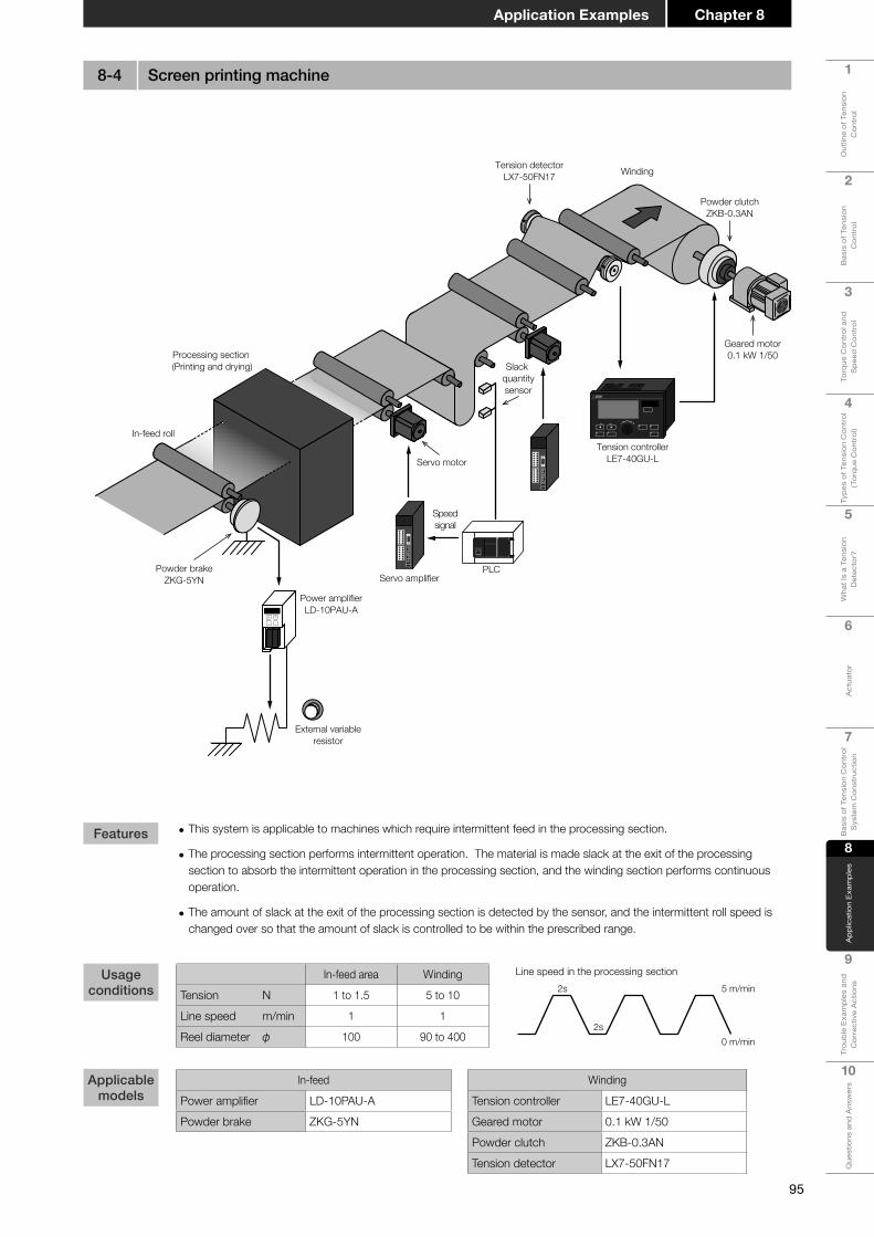
95
1
Out
line
of T
ensi
on
Con
trol
2
Bas
is o
f Ten
sion
C
ontr
ol
3
Torq
ue C
ontr
ol a
nd
Spe
ed C
ontr
ol
4
Type
s of
Ten
sion
Con
trol
(T
orqu
e C
ontr
ol)
5
Wha
t Is
a Te
nsio
n D
etec
tor?
6
Act
uato
r
7
Bas
is o
f Ten
sion
Con
trol
S
yste
m C
onst
ruct
ion
8A
pplic
atio
n Ex
ampl
es
9
Trou
ble
Exam
ples
and
C
orre
ctiv
e A
ctio
ns
10
Que
stio
ns a
nd A
nsw
ers
Chapter 8Application Examples
Servo motor
Processing section (Printing and drying)
In-feed roll
WindingTension detectorLX7-50FN17
Powder clutchZKB-0.3AN
Geared motor0.1 kW 1/50
Tension controllerLE7-40GU-L
Power amplifierLD-10PAU-A
Powder brakeZKG-5YN
External variableresistor
PLC
Speedsignal
Slack quantitysensor
Servo amplifier
• This system is applicable to machines which require intermittent feed in the processing section.
• The processing section performs intermittent operation. The material is made slack at the exit of the processing section to absorb the intermittent operation in the processing section, and the winding section performs continuous operation.
• The amount of slack at the exit of the processing section is detected by the sensor, and the intermittent roll speed is changed over so that the amount of slack is controlled to be within the prescribed range.
In-feed area WindingTension N 1 to 1.5 5 to 10
Line speed m/min 1 1
Reel diameter φ 100 90 to 400
In-feed
Power amplifier LD-10PAU-APowder brake ZKG-5YN
Winding
Tension controller LE7-40GU-LGeared motor 0.1 kW 1/50Powder clutch ZKB-0.3ANTension detector LX7-50FN17
2s
2s
5 m/min
Line speed in the processing section
0 m/min
Features
Usage conditions
Applicable models
8-4 Screen printing machine
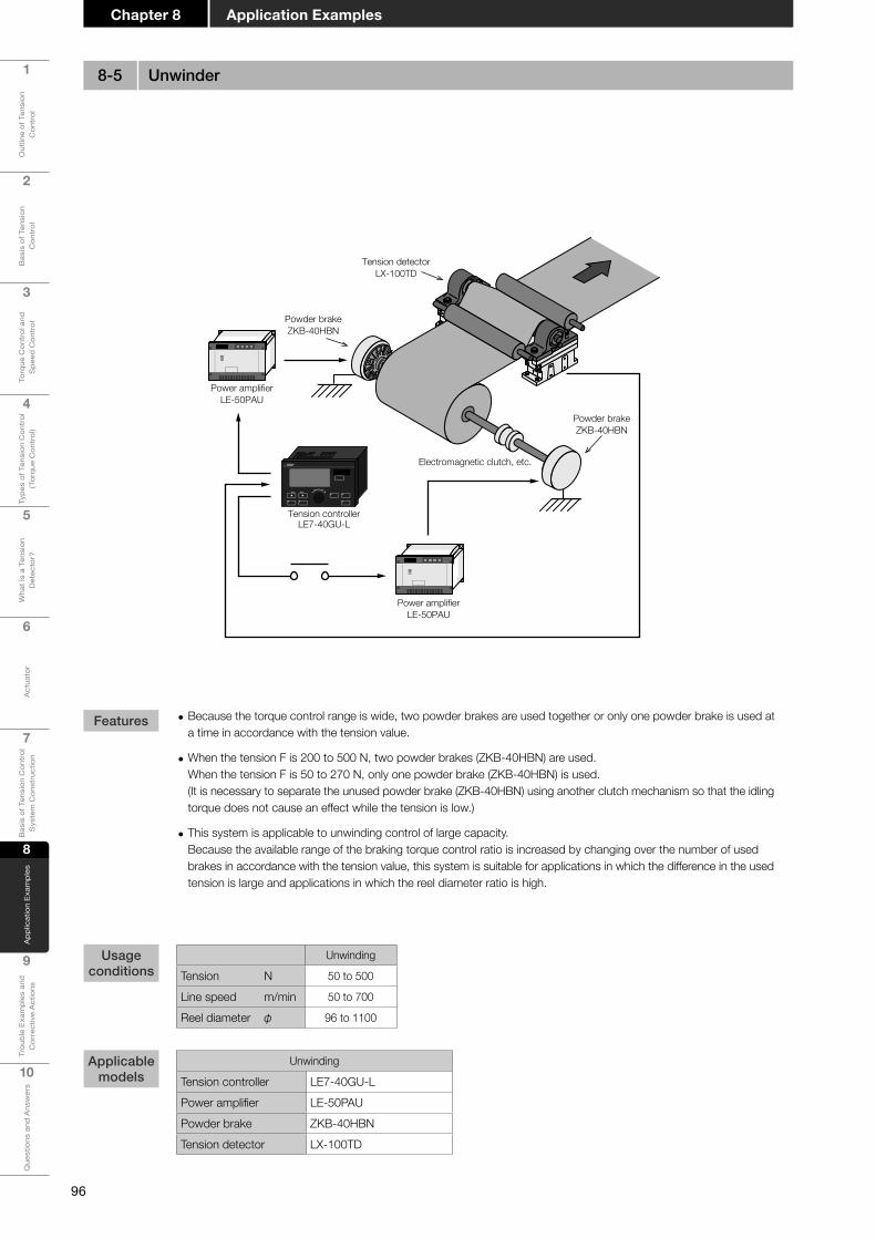
96
1
Out
line
of T
ensi
on
Con
trol
2
Bas
is o
f Ten
sion
C
ontr
ol
3
Torq
ue C
ontr
ol a
nd
Spe
ed C
ontr
ol
4
Type
s of
Ten
sion
Con
trol
(T
orqu
e C
ontr
ol)
5
Wha
t Is
a Te
nsio
n D
etec
tor?
6
Act
uato
r
7
Bas
is o
f Ten
sion
Con
trol
S
yste
m C
onst
ruct
ion
8
App
licat
ion
Exam
ples
9
Trou
ble
Exam
ples
and
C
orre
ctiv
e A
ctio
ns
10
Que
stio
ns a
nd A
nsw
ers
Application ExamplesChapter 8
Electromagnetic clutch, etc.
Powder brakeZKB-40HBN
Tension detectorLX-100TD
Powder brakeZKB-40HBN
Power amplifierLE-50PAU
Tension controllerLE7-40GU-L
Power amplifierLE-50PAU
• Because the torque control range is wide, two powder brakes are used together or only one powder brake is used at a time in accordance with the tension value.
• When the tension F is 200 to 500 N, two powder brakes (ZKB-40HBN) are used. When the tension F is 50 to 270 N, only one powder brake (ZKB-40HBN) is used. (It is necessary to separate the unused powder brake (ZKB-40HBN) using another clutch mechanism so that the idling torque does not cause an effect while the tension is low.)
• This system is applicable to unwinding control of large capacity. Because the available range of the braking torque control ratio is increased by changing over the number of used brakes in accordance with the tension value, this system is suitable for applications in which the difference in the used tension is large and applications in which the reel diameter ratio is high.
Unwinding
Tension N 50 to 500
Line speed m/min 50 to 700
Reel diameter φ 96 to 1100
Unwinding
Tension controller LE7-40GU-LPower amplifier LE-50PAUPowder brake ZKB-40HBNTension detector LX-100TD
Features
Usage conditions
Applicable models
8-5 Unwinder

97
1
Out
line
of T
ensi
on
Con
trol
2
Bas
is o
f Ten
sion
C
ontr
ol
3
Torq
ue C
ontr
ol a
nd
Spe
ed C
ontr
ol
4
Type
s of
Ten
sion
Con
trol
(T
orqu
e C
ontr
ol)
5
Wha
t Is
a Te
nsio
n D
etec
tor?
6
Act
uato
r
7
Bas
is o
f Ten
sion
Con
trol
S
yste
m C
onst
ruct
ion
8A
pplic
atio
n Ex
ampl
es
9
Trou
ble
Exam
ples
and
C
orre
ctiv
e A
ctio
ns
10
Que
stio
ns a
nd A
nsw
ers
Chapter 8Application Examples
ZKB-2.5BNPowder clutch
Geared motor0.2 kW 1/60
Feed roll
Punching section
Proximity switch
Open-loop type tension controllerLD-30FTA
• The material does not travel but is fed intermittently during punching. This system controls the tension in the winding section.
• Though the material is fed intermittently, the geared motor for winding is always rotating so that the material is stretched properly even in the stop status.
• Because intermittent operation is required, the reel diameter detection type tension controller, which offers stable control, is adopted.
• Because the material thickness is 200 μm, the reel shaft pulse number is set to "10 pulses/rotation" and the material thickness is set to "20 μm (= 200 × 1/10)".
• This system is applicable to machines requiring intermittent feed such as hot stamping machines and screen printing machines.
Winding
Tension N 50 to 100
Line speed m/min 6 or less
Reel diameter φ 92 to 500
Winding
Tension controller LD-30FTAPowder clutch ZKB-2.5BNGeared motor 0.2 kW 1/60
Material Paper (Thickness: 200 μm)Number of times of intermittent feed 10 times/min
Features
Usage conditions
Applicable models
8-6 Punching machine

98
1
Out
line
of T
ensi
on
Con
trol
2
Bas
is o
f Ten
sion
C
ontr
ol
3
Torq
ue C
ontr
ol a
nd
Spe
ed C
ontr
ol
4
Type
s of
Ten
sion
Con
trol
(T
orqu
e C
ontr
ol)
5
Wha
t Is
a Te
nsio
n D
etec
tor?
6
Act
uato
r
7
Bas
is o
f Ten
sion
Con
trol
S
yste
m C
onst
ruct
ion
8
App
licat
ion
Exam
ples
9
Trou
ble
Exam
ples
and
C
orre
ctiv
e A
ctio
ns
10
Que
stio
ns a
nd A
nsw
ers
Application ExamplesChapter 8
Air compressor
Powder clutchZKB-5BN
Polyethylenematerial
Geared motor1.5 kW 1/10
Winder ATurret
Tension detectorLX7-150FN17
Edge winding
Winder B
Tension controllerLE7-40GU-L
Tension controllerLE7-40GU-L
• The inflatable extruder extrudes polyethylene film into a cylindrical shape. The cylindrical film is folded in half, cut at both edges, and shaped into two sheets.
• The material film is cooled in this period, and each of the two sheets is wound by the 2-shaft turret type automatic winder respectively. Tension control equipment is used also in this type of application.
• Because the LE7-40GU-L incorporates the new shaft preset (new shaft predrive output) function, a simple parameter setting procedure enables automatic paper splicing using the 2-shaft turret machine.
• Because the LE7-40GU-L incorporates the cut gain (cut torque) function, film can be cut easily.
• This system is applicable to shaft changeover machines using the powder clutch.
Winding
Tension N 15 to 25
Line speed m/min 50 to 150
Reel diameter φ 100 to 900
Winding
Tension controller LE7-40GU-L × 2 unitsTension detector LX7-150FN17Powder clutch ZKB-5BN (Forced air cooling)Geared motor 1.5 kW 1/10
Protective element
Commutation diode 200 VA 5 AProtective resistor 10 W 47 Ω
When the reel is changed over between two shafts, the powder clutch is changed over by the external contact. Make sure to install the protective diode and resistor in parallel with two powder clutches.
Features
Usage conditions
Applicable models
8-7 Inflatableextruder+2-shaftfilmwinder

99
1
Out
line
of T
ensi
on
Con
trol
2
Bas
is o
f Ten
sion
C
ontr
ol
3
Torq
ue C
ontr
ol a
nd
Spe
ed C
ontr
ol
4
Type
s of
Ten
sion
Con
trol
(T
orqu
e C
ontr
ol)
5
Wha
t Is
a Te
nsio
n D
etec
tor?
6
Act
uato
r
7
Bas
is o
f Ten
sion
Con
trol
S
yste
m C
onst
ruct
ion
8A
pplic
atio
n Ex
ampl
es
9
Trou
ble
Exam
ples
and
C
orre
ctiv
e A
ctio
ns
10
Que
stio
ns a
nd A
nsw
ers
Chapter 8Application Examples
LD-10WTB-CCL
Rotary encoder
Cutter
Feed roll
Proximity switch
Tension controller
Powder brakeZA-40Y
Adjustmentvariable resistor
Power amplifierLE-50PAU
• Because several sheets of paper are cut all at once, the tension of every sheet is kept constant to reduce the dimensional misalignment.
• The reel diameter is detected in the representative reel, and four powder brakes are controlled.
• The diameter of the four reels in the unwinding section must be the same.
• Adjustment variable resistor are used to fine-adjust the tension of each shaft.
• This system is applicable to multi-shaft unwinding in the sizing machine, etc.
Winding
Tension N 300 to 500
Line speed m/min 60 to 100
Reel diameter φ 100 to 1200
Winding
Tension controller LD-10WTB-CCLPower amplifier LE-50PAU × 4 unitsPowder brake ZA-40Y × 4 units
Material Paper
Features
Usage conditions
Applicable models
8-8 Multiple cutter
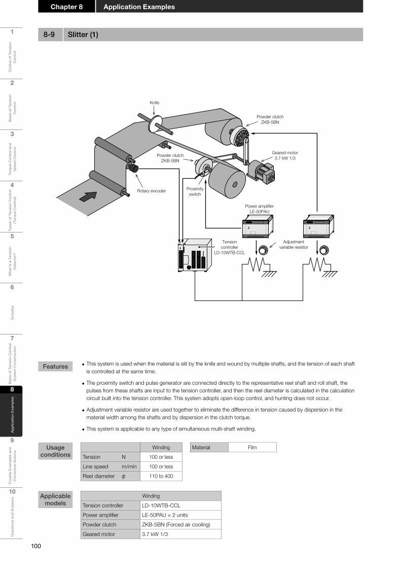
100
1
Out
line
of T
ensi
on
Con
trol
2
Bas
is o
f Ten
sion
C
ontr
ol
3
Torq
ue C
ontr
ol a
nd
Spe
ed C
ontr
ol
4
Type
s of
Ten
sion
Con
trol
(T
orqu
e C
ontr
ol)
5
Wha
t Is
a Te
nsio
n D
etec
tor?
6
Act
uato
r
7
Bas
is o
f Ten
sion
Con
trol
S
yste
m C
onst
ruct
ion
8
App
licat
ion
Exam
ples
9
Trou
ble
Exam
ples
and
C
orre
ctiv
e A
ctio
ns
10
Que
stio
ns a
nd A
nsw
ers
Application ExamplesChapter 8
Powder clutchZKB-5BN
Geared motor3.7 kW 1/3Powder clutch
ZKB-5BN
Knife
Adjustmentvariable resistor
Power amplifierLE-50PAU
Proximityswitch
Rotary encoder
Tensioncontroller
LD-10WTB-CCL
• This system is used when the material is slit by the knife and wound by multiple shafts, and the tension of each shaft is controlled at the same time.
• The proximity switch and pulse generator are connected directly to the representative reel shaft and roll shaft, the pulses from these shafts are input to the tension controller, and then the reel diameter is calculated in the calculation circuit built into the tension controller. This system adopts open-loop control, and hunting does not occur.
• Adjustment variable resistor are used together to eliminate the difference in tension caused by dispersion in the material width among the shafts and by dispersion in the clutch torque.
• This system is applicable to any type of simultaneous multi-shaft winding.
Winding
Tension N 100 or less
Line speed m/min 100 or less
Reel diameter φ 110 to 400
Winding
Tension controller LD-10WTB-CCLPower amplifier LE-50PAU × 2 unitsPowder clutch ZKB-5BN (Forced air cooling)Geared motor 3.7 kW 1/3
Material Film
Features
Usage conditions
Applicable models
8-9 Slitter (1)
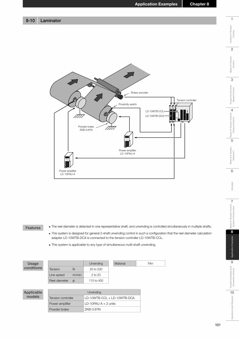
101
1
Out
line
of T
ensi
on
Con
trol
2
Bas
is o
f Ten
sion
C
ontr
ol
3
Torq
ue C
ontr
ol a
nd
Spe
ed C
ontr
ol
4
Type
s of
Ten
sion
Con
trol
(T
orqu
e C
ontr
ol)
5
Wha
t Is
a Te
nsio
n D
etec
tor?
6
Act
uato
r
7
Bas
is o
f Ten
sion
Con
trol
S
yste
m C
onst
ruct
ion
8A
pplic
atio
n Ex
ampl
es
9
Trou
ble
Exam
ples
and
C
orre
ctiv
e A
ctio
ns
10
Que
stio
ns a
nd A
nsw
ers
Chapter 8Application Examples
Rotary encoder
Tension controllerProximity switch
Powder brakeZKB-0.6YN
Power amplifierLD-10PAU-A
LD-10WTB-CCL
LD-10WTB-DCA
Power amplifierLD-10PAU-A
• The reel diameter is detected in one representative shaft, and unwinding is controlled simultaneously in multiple shafts.
• This system is designed for general 2-shaft unwinding control in such a configuration that the reel diameter calculation adapter LD-10WTB-DCA is connected to the tension controller LD-10WTB-CCL.
• This system is applicable to any type of simultaneous multi-shaft unwinding.
Unwinding
Tension N 20 to 200
Line speed m/min 2 to 20
Reel diameter φ 110 to 400
Unwinding
Tension controller LD-10WTB-CCL + LD-10WTB-DCAPower amplifier LD-10PAU-A × 2 unitsPowder brake ZKB-0.6YN
Material Film
Features
Usage conditions
Applicable models
8-10 Laminator

102
1
Out
line
of T
ensi
on
Con
trol
2
Bas
is o
f Ten
sion
C
ontr
ol
3
Torq
ue C
ontr
ol a
nd
Spe
ed C
ontr
ol
4
Type
s of
Ten
sion
Con
trol
(T
orqu
e C
ontr
ol)
5
Wha
t Is
a Te
nsio
n D
etec
tor?
6
Act
uato
r
7
Bas
is o
f Ten
sion
Con
trol
S
yste
m C
onst
ruct
ion
8
App
licat
ion
Exam
ples
9
Trou
ble
Exam
ples
and
C
orre
ctiv
e A
ctio
ns
10
Que
stio
ns a
nd A
nsw
ers
Application ExamplesChapter 8
Air brake
Load cell
Feed roll
Electro-pneumaticconverter
LE-10WTA-CCLTension controller
• The air brake and load call control the tension for unwinding at high tension of metallic materials such as thin steel plate and aluminum plate.
• Because the tension is high, a commercial load cell is used as the detector, and the detected load is input to the tension controller.
• This system is applicable also to winders requiring high tension.
Unwinding
Tension N 10000 or less
Line speed m/min 70 or less
Reel diameter φ 250 to 1200
UnwindingTension controller LE-10WTA-CCLAir brake Product manufactured by another companyElectro-pneumatic converter Product manufactured by another company
Material Thin steel plate
Features
Usage conditions
Applicable models
8-11 Rolling machine
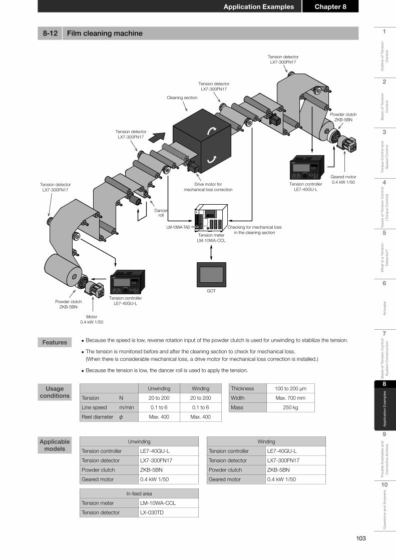
103
1
Out
line
of T
ensi
on
Con
trol
2
Bas
is o
f Ten
sion
C
ontr
ol
3
Torq
ue C
ontr
ol a
nd
Spe
ed C
ontr
ol
4
Type
s of
Ten
sion
Con
trol
(T
orqu
e C
ontr
ol)
5
Wha
t Is
a Te
nsio
n D
etec
tor?
6
Act
uato
r
7
Bas
is o
f Ten
sion
Con
trol
S
yste
m C
onst
ruct
ion
8A
pplic
atio
n Ex
ampl
es
9
Trou
ble
Exam
ples
and
C
orre
ctiv
e A
ctio
ns
10
Que
stio
ns a
nd A
nsw
ers
Chapter 8Application Examples
Powder clutchZKB-5BN
Powder clutchZKB-5BN
Geared motor0.4 kW 1/50
Motor0.4 kW 1/50
Dancerroll
Tension detectorLX7-300FN17
Checking for mechanical lossin the cleaning section
Drive motor formechanical loss correction
Tension detectorLX7-300FN17
Tension detectorLX7-300FN17
Cleaning section
Tension detectorLX7-300FN17
Tension controllerLE7-40GU-L
Tension meterLM-10WA-CCL
GOT
Tension controllerLE7-40GU-L
LM-10WA-TAD
• Because the speed is low, reverse rotation input of the powder clutch is used for unwinding to stabilize the tension.
• The tension is monitored before and after the cleaning section to check for mechanical loss. (When there is considerable mechanical loss, a drive motor for mechanical loss correction is installed.)
• Because the tension is low, the dancer roll is used to apply the tension.
Unwinding Winding
Tension N 20 to 200 20 to 200
Line speed m/min 0.1 to 6 0.1 to 6
Reel diameter φ Max. 400 Max. 400
Thickness 100 to 200 μm
Width Max. 700 mm
Mass 250 kg
Winding
Tension controller LE7-40GU-LTension detector LX7-300FN17Powder clutch ZKB-5BNGeared motor 0.4 kW 1/50
Unwinding
Tension controller LE7-40GU-LTension detector LX7-300FN17Powder clutch ZKB-5BNGeared motor 0.4 kW 1/50
In-feed area
Tension meter LM-10WA-CCLTension detector LX-030TD
Features
Usage conditions
Applicable models
8-12 Film cleaning machine
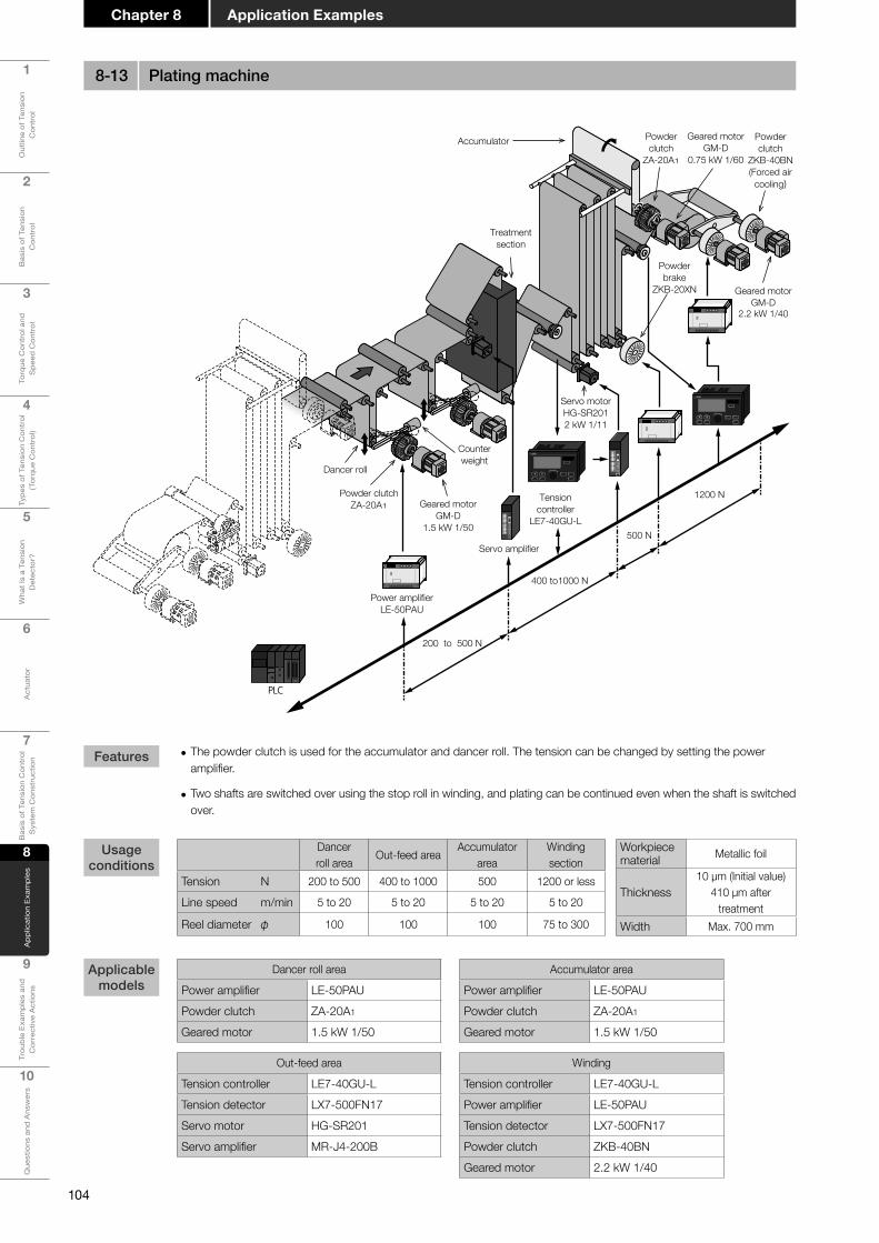
104
1
Out
line
of T
ensi
on
Con
trol
2
Bas
is o
f Ten
sion
C
ontr
ol
3
Torq
ue C
ontr
ol a
nd
Spe
ed C
ontr
ol
4
Type
s of
Ten
sion
Con
trol
(T
orqu
e C
ontr
ol)
5
Wha
t Is
a Te
nsio
n D
etec
tor?
6
Act
uato
r
7
Bas
is o
f Ten
sion
Con
trol
S
yste
m C
onst
ruct
ion
8
App
licat
ion
Exam
ples
9
Trou
ble
Exam
ples
and
C
orre
ctiv
e A
ctio
ns
10
Que
stio
ns a
nd A
nsw
ers
Application ExamplesChapter 8
Tensioncontroller
LE7-40GU-L
Powderbrake
ZKB-20XN
Powder clutchZA-20A1
Powderclutch
ZA-20A1
Geared motorGM-D
1.5 kW 1/50
Accumulator
Geared motorGM-D
2.2 kW 1/40
Powderclutch
ZKB-40BN(Forced air
cooling)
Geared motorGM-D
0.75 kW 1/60
Treatmentsection
PLC
Dancer roll
Servo motorHG-SR2012 kW 1/11
Power amplifierLE-50PAU
Servo amplifier
200 to 500 N
400 to1000 N
1200 N
500 N
Counterweight
• The powder clutch is used for the accumulator and dancer roll. The tension can be changed by setting the power amplifier.
• Two shafts are switched over using the stop roll in winding, and plating can be continued even when the shaft is switched over.
Dancer roll area Out-feed area Accumulator
areaWinding section
Tension N 200 to 500 400 to 1000 500 1200 or less
Line speed m/min 5 to 20 5 to 20 5 to 20 5 to 20
Reel diameter φ 100 100 100 75 to 300
Workpiece material Metallic foil
Thickness10 μm (Initial value)
410 μm after treatment
Width Max. 700 mm
Out-feed area
Tension controller LE7-40GU-LTension detector LX7-500FN17Servo motor HG-SR201Servo amplifier MR-J4-200B
Winding
Tension controller LE7-40GU-LPower amplifier LE-50PAUTension detector LX7-500FN17Powder clutch ZKB-40BNGeared motor 2.2 kW 1/40
Accumulator area
Power amplifier LE-50PAUPowder clutch ZA-20A1
Geared motor 1.5 kW 1/50
Dancer roll area
Power amplifier LE-50PAUPowder clutch ZA-20A1
Geared motor 1.5 kW 1/50
Features
Usage conditions
Applicable models
8-13 Plating machine

105
1
Out
line
of T
ensi
on
Con
trol
2
Bas
is o
f Ten
sion
C
ontr
ol
3
Torq
ue C
ontr
ol a
nd
Spe
ed C
ontr
ol
4
Type
s of
Ten
sion
Con
trol
(T
orqu
e C
ontr
ol)
5
Wha
t Is
a Te
nsio
n D
etec
tor?
6
Act
uato
r
7
Bas
is o
f Ten
sion
Con
trol
S
yste
m C
onst
ruct
ion
8A
pplic
atio
n Ex
ampl
es
9
Trou
ble
Exam
ples
and
C
orre
ctiv
e A
ctio
ns
10
Que
stio
ns a
nd A
nsw
ers
Chapter 8Application Examples
GOT
Servo amplifierMR-J4-60
Servo motorHG-SR51
Powder clutchZKB-0.3AN
Geared motor0.1 kW 1/5
Ultrasonic sensor
Power amplifierLD-10PAU-A
PLC
Tension controllerLE-10WTA-CCL
Stop rollAccumulator
Tension detectorLX-050TD
• The PLC receives the reel diameter signal from the ultrasonic sensor, and performs external taper control.
• The shaft is changed over during winding using the stop roll.
• The accumulator controls the tension using the powder clutch.
Accumulator Winding
Tension N 20 to 50 20 to 50
Line speed m/min Max. 75 Max. 75
Reel diameter φ 100 96 to 400
Winding
Tension controller LE-10WTA-CCLTension detector LX-050TDServo motor HG-SR51Servo amplifier MR-J4-60
Accumulator
Power amplifier LD-10PAU-APowder clutch ZKB-0.3ANGeared motor 0.1 kW 1/5
Features
Usage conditions
Applicable models
8-14 Winder
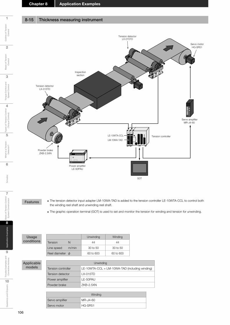
106
1
Out
line
of T
ensi
on
Con
trol
2
Bas
is o
f Ten
sion
C
ontr
ol
3
Torq
ue C
ontr
ol a
nd
Spe
ed C
ontr
ol
4
Type
s of
Ten
sion
Con
trol
(T
orqu
e C
ontr
ol)
5
Wha
t Is
a Te
nsio
n D
etec
tor?
6
Act
uato
r
7
Bas
is o
f Ten
sion
Con
trol
S
yste
m C
onst
ruct
ion
8
App
licat
ion
Exam
ples
9
Trou
ble
Exam
ples
and
C
orre
ctiv
e A
ctio
ns
10
Que
stio
ns a
nd A
nsw
ers
Application ExamplesChapter 8
Servo motorHG-SR51
Powder brakeZKB-2.5XN
Tension detectorLX-015TD
Inspectionsection
Power amplifierLE-50PAU
LE-10WTA-CCL
LM-10WA-TAD
GOT
Servo amplifierMR-J4-60
Tension controller
Tension detectorLX-015TD
• The tension detector input adapter LM-10WA-TAD is added to the tension controller LE-10WTA-CCL to control both the winding reel shaft and unwinding reel shaft.
• The graphic operation terminal (GOT) is used to set and monitor the tension for winding and tension for unwinding.
Unwinding Winding
Tension N 44 44
Line speed m/min 30 to 50 30 to 50
Reel diameter φ 60 to 600 60 to 600
Unwinding
Tension controller LE-10WTA-CCL + LM-10WA-TAD (including winding)Tension detector LX-015TDPower amplifier LE-50PAUPowder brake ZKB-2.5XN
Winding
Servo amplifier MR-J4-60Servo motor HG-SR51
Features
Usage conditions
Applicable models
8-15 Thickness measuring instrument

107
1
Out
line
of T
ensi
on
Con
trol
2
Bas
is o
f Ten
sion
C
ontr
ol
3
Torq
ue C
ontr
ol a
nd
Spe
ed C
ontr
ol
4
Type
s of
Ten
sion
Con
trol
(T
orqu
e C
ontr
ol)
5
Wha
t Is
a Te
nsio
n D
etec
tor?
6
Act
uato
r
7
Bas
is o
f Ten
sion
Con
trol
S
yste
m C
onst
ruct
ion
8A
pplic
atio
n Ex
ampl
es
9
Trou
ble
Exam
ples
and
C
orre
ctiv
e A
ctio
ns
10
Que
stio
ns a
nd A
nsw
ers
Chapter 8Application Examples
GOT
Power amplifierLD-10PAU-B
Powder clutchZKB-1.2BN
Geared motor0.75 kW 1/25
• Because there are many roll shafts, the total mechanical loss is large. To reduce the mechanical loss, a powder clutch is installed in each roll shaft to apply driving corresponding to the mechanical loss and eliminate its effect. This system is effective when there are many shafts but low-tension operation is required.
• Many amplifiers are connected through RS-485 communication, and one graphic operation terminal (GOT) sets the parameters of many amplifiers in a batch.
Mechanical loss N 1 to 7
Line speed m/min 0.5 to 5
Roll diameter φ 250
Powder clutch ZKB-1.2BNPower amplifier LD-10PAU-BGeared motor 0.75 kW 1/25
Features
Usage conditions
Applicable models
8-16 Steel plate plating line

108
1
Out
line
of T
ensi
on
Con
trol
2
Bas
is o
f Ten
sion
C
ontr
ol
3
Torq
ue C
ontr
ol a
nd
Spe
ed C
ontr
ol
4
Type
s of
Ten
sion
Con
trol
(T
orqu
e C
ontr
ol)
5
Wha
t Is
a Te
nsio
n D
etec
tor?
6
Act
uato
r
7
Bas
is o
f Ten
sion
Con
trol
S
yste
m C
onst
ruct
ion
8
App
licat
ion
Exam
ples
9
Trou
ble
Exam
ples
and
C
orre
ctiv
e A
ctio
ns
10
Que
stio
ns a
nd A
nsw
ers
Application ExamplesChapter 8
Servo motor
Ultrasonic sensor
Powder clutchZA-2.5A1
Powder clutchZA-5A1
Tension controllerLE7-40GU-L
Open-loop type tension controllerLD-30FTA
Open-loop type tension controllerLD-30FTA
Tension controllerLE7-40GU-L
Tension meterLM-10PD
Tension detectorLX7-150FN17
Treatment section
Geared motor0.2 kW 1/40
Geared motor0.4 kW 1/40
Powder clutchZA-5A1
Powder clutchZA-2.5A1
Servo amplifier
Shaft A
Shaft A
Shaft B
Shaft B
Geared motor0.4 kW 1/40
Geared motor0.2 kW 1/40
• Because the hunting phenomenon could occur when the reel shaft is rotating at extremely low (rotation) speed if a servo motor is used, a powder clutch is adopted.
• Because the line speed is extremely low, reverse rotation input of the powder clutch is effective in the unwinding section.
• Because the distance between rollers is short in the treatment section, draw control is adopted instead of the dancer roll.
Unwinding WindingTension N 30 to 100 30 to 100Line speed m/min 1 to 15 1 to 15
Reel diameter φ 85 to 400 85 to 400
Unwinding
Shaft A
Tension controller LE7-40GU-LTension detector LX7-150FN17
Powder clutch ZA-2.5A1(Reverse rotation input)
Geared motor 0.2 kW 1/40
Shaft B
Tension controller LD-30FTA
Powder clutch ZA-2.5A1(Reverse rotation input)
Geared motor 0.2 kW 1/40
In-feed areaTension detector LX7-150FN17Tension meter LM-10PD
Winding
Shaft A
Tension controller LE7-40GU-LTension detector LX7-150FN17Powder clutch ZA-5A1
Geared motor 0.4 kW 1/40
Shaft B
Tension controller LD-30FTA
Powder clutch ZA-5A1(Reverse rotation input)
Geared motor 0.4 kW 1/40
Features
Usage conditions
Applicable models
8-17 Static electricity eliminating device

109
1
Out
line
of T
ensi
on
Con
trol
2
Bas
is o
f Ten
sion
C
ontr
ol
3
Torq
ue C
ontr
ol a
nd
Spe
ed C
ontr
ol
4
Type
s of
Ten
sion
Con
trol
(T
orqu
e C
ontr
ol)
5
Wha
t Is
a Te
nsio
n D
etec
tor?
6
Act
uato
r
7
Bas
is o
f Ten
sion
Con
trol
S
yste
m C
onst
ruct
ion
8A
pplic
atio
n Ex
ampl
es
9
Trou
ble
Exam
ples
and
C
orre
ctiv
e A
ctio
ns
10
Que
stio
ns a
nd A
nsw
ers
Chapter 8Application Examples
Powder clutchZA-1.2A1
Constant-torquemotor
SF-HRCA-71M
Proximity switch
Powder clutchZKB-1.2BN
Geared motor0.2 kW 1/40
Tension detectorLX-015TD
Slitter (Knife)
Rotary encoder
Edgewinding
LD-10WTB-CCL
Tension controller
LM-10WA-TAD
LM-10WA-TAD
InverterFR-A820-0.4K
Power amplifierLE-50PAU
Power amplifierLE-50PAU
• Constant-slip control is adopted in the winding section to mitigate the increase of the powder clutch capacity.
• External taper control is adopted so that the taper ratio can be changed in accordance with the reel diameter.
• Reverse input is adopted on the unwinding side because the line speed may be low.
Unwinding WindingTension N 10 to 50 10 to 50Line speed m/min 5 to 30 5 to 30Reel diameter φ 96.2 to 600 96.2 to 600
Thickness 0.2 to 1.2 mmWidth 500 to 1200 mmMass Max. 280 kg
UnwindingTension detector LX-015TDPower amplifier LE-50PAUPowder clutch ZKB-1.2BNGeared motor 0.2 kW 1/40
Winding
Tension controller LD-10WTB-CCL + LM-10WA-TAD × 2 units or LE-10-WTA-CCL + LM-10WA-TAD + LD-10WTB-DCA
Tension detector LX-015TDPower amplifier LE-50PAUPowder clutch ZA-1.2A1
Constant-torque motor SF-HRCA-71MInverter FR-A820-0.4K
Features
Usage conditions
Applicable models
8-18 Slitter (2)

110
1
Out
line
of T
ensi
on
Con
trol
2
Bas
is o
f Ten
sion
C
ontr
ol
3
Torq
ue C
ontr
ol a
nd
Spe
ed C
ontr
ol
4
Type
s of
Ten
sion
Con
trol
(T
orqu
e C
ontr
ol)
5
Wha
t Is
a Te
nsio
n D
etec
tor?
6
Act
uato
r
7
Bas
is o
f Ten
sion
Con
trol
S
yste
m C
onst
ruct
ion
8
App
licat
ion
Exam
ples
9
Trou
ble
Exam
ples
and
C
orre
ctiv
e A
ctio
ns
10
Que
stio
ns a
nd A
nsw
ers
Application ExamplesChapter 8
Open-loop type tension controllerLD-30FTA
Tension controllerLE7-40GU-L
Tension controllerLE7-40GU-L
Tension controllerLE7-40GU-L
Powder brakeZKB-0.6YN
Powder clutchZKB-0.6AN
Proximityswitch
Geared motor0.2 kW 1/20
Tension detectorLX7-150FN17
Powder clutchZKB-2.5BN
Geared motor0.4 kW 1/40
Powder brakeZKB-0.3YN
Winding B
Unwinding AB
Winding AC
Unwinding C
• Feedback control is adopted on the unwinding side to improve the torque stability in the low torque region. (Closed-loop control is recommended in areas whose torque is 5% or less in the powder clutch/brake.)
Unwinding Unwinding Winding Winding
AB C B AC
Tension N 30 to 100 20 to 50 20 to 50 30 to 100
Line speed m/min 2 to 8 2 to 8 2 to 8 2 to 8
Reel diameter φ 75 to 450 75 to 250 75 to 250 75 to 450
Unwinding
ABUnwinding
Tension controller LE7-40GU-L
Tension detector LX7-150FN17Powder brake ZKB-0.6YN
CUnwinding
Tension controller LE7-40GU-LTension detector LX7-150FN17Powder brake ZKB-0.3YN
Winding
BWinding
Tension controller LD-30FTATension detector LX7-150FN17Powder clutch ZKB-0.6ANGeared motor 0.2 kW 1/20
ACWinding
Tension controller LE7-40GU-LTension detector LX7-150FN17Powder clutch ZKB-2.5BNGeared motor 0.4 kW 1/40
Features
Usage conditions
Applicable models
8-19 Laminator

111
1
Out
line
of T
ensi
on
Con
trol
2
Bas
is o
f Ten
sion
C
ontr
ol
3
Torq
ue C
ontr
ol a
nd
Spe
ed C
ontr
ol
4
Type
s of
Ten
sion
Con
trol
(T
orqu
e C
ontr
ol)
5
Wha
t Is
a Te
nsio
n D
etec
tor?
6
Act
uato
r
7
Bas
is o
f Ten
sion
Con
trol
S
yste
m C
onst
ruct
ion
8A
pplic
atio
n Ex
ampl
es
9
Trou
ble
Exam
ples
and
C
orre
ctiv
e A
ctio
ns
10
Que
stio
ns a
nd A
nsw
ers
Chapter 8Application Examples
Powder brakeZKB-1.2XN
Tension detectorLX-015TD
Accumulator
Punch
Geared motor1.5 kW 1/10
Air cylinder
Powder clutchZKB-5BN
(Forced air cooling)Tension detectorLX-015TD
Tension controllerLE7-40GU-L
Accumulator
Air cylinder
Tension controllerLE7-40GU-L
Inverter
Inverter
• Because intermittent operation is performed for pressing the film, an accumulator is installed so that the processing does not stop.
• The forced air cooling type powder clutch is adopted in the winding section to improve heat radiation.
Unwinding Winding
Tension N 75 75
Line speed m/min 10 to 40 10 to 40
Reel diameter φ 90 to 800 90 to 800
Unwinding
Tension controller LE7-40GU-LTension detector LX-015TDPowder brake ZKB-1.2XN
Winding
Tension controller LE7-40GU-LTension detector LX-015TDPowder clutch ZKB-5BN (Forced air cooling)Geared motor 1.5 kW 1/10
Features
Usage conditions
Applicable models
8-20 Film processing machine

112
1
Out
line
of T
ensi
on
Con
trol
2
Bas
is o
f Ten
sion
C
ontr
ol
3
Torq
ue C
ontr
ol a
nd
Spe
ed C
ontr
ol
4
Type
s of
Ten
sion
Con
trol
(T
orqu
e C
ontr
ol)
5
Wha
t Is
a Te
nsio
n D
etec
tor?
6
Act
uato
r
7
Bas
is o
f Ten
sion
Con
trol
S
yste
m C
onst
ruct
ion
8
App
licat
ion
Exam
ples
9
Trou
ble
Exam
ples
and
C
orre
ctiv
e A
ctio
ns
10
Que
stio
ns a
nd A
nsw
ers
Application ExamplesChapter 8
MEMO
Chapter 9
Trouble Examples and Corrective Actions
Trouble Examples and Corrective Actions
ERR!

Chapter 9 Fault Examples and Corrective Actions
1
Out
line
of T
ensi
on
Con
trol
2
Bas
is o
f Ten
sion
C
ontr
ol
3
Torq
ue C
ontr
ol a
nd
Spe
ed C
ontr
ol
4
Type
s of
Ten
sion
Con
trol
(T
orqu
e C
ontr
ol)
5
Wha
t Is
a Te
nsio
n D
etec
tor?
6
Act
uato
r
7
Bas
is o
f Ten
sion
Con
trol
S
yste
m C
onst
ruct
ion
8
App
licat
ion
Exam
ples
9
Trou
ble
Exam
ples
and
C
orre
ctiv
e A
ctio
ns
10
Que
stio
ns a
nd A
nsw
ers
114
Phenomenon Countermeasures
Clutch/brake
Though the powder clutch/brake is used at the rated or lower torque, its temperature becomes extremely high.The surface temperature becomes 100°C or more.
Overload may be applied.The powder clutch/brake may be unavailable even if the used torque does not exceed the rated torque.It is necessary to check the heat dissipation (which is the product of the torque and slip rotation speed) based on the usage conditions.It is necessary to restrict the torque when the slip rotation speed is high. Refer to the catalog for the allowable heat dissipation.
The powder brake wobbles (does not rotate smoothly) at low speed.This phenomenon often occurs when the reel diameter is large.
The stick slip phenomenon may have occurred in the powder brake.The stick slip phenomenon occurs more often when the reel diameter is large (that is, the load is large and the rotation speed is low), and occurs less often as the reel diameter becomes smaller (that is, the load is small and the rotation speed is high).The stick slip phenomenon occurs easily in the unwinding section (powder brake) when the line speed is low (10 m/min. or less). The countermeasure is to increase the slip rotation speed. It is effective to replace the powder brake with the combination of "powder clutch and reverse rotation motor".Other possible factors on the machine side except the powder brake are the tension of the timing belt and the backlash of the gear. A possible factor on the material side is elongation/shrinkage of the material.
In the ZA type clutch, the bearing locks early. The idling torque is large.
The coil locking bolts may be overtightened.If the coil locking bolts are overtightened on the mounting plate, excessive thrust load is applied to the bearing.When fixing the coil locking bolts on the mounting plate, provide proper backlash in both the axial direction and the rotation direction so that the thrust load is not applied to the bearing.
Tension controller
The tension is too high at startup in the tension feedback type control.The material breaks off.
Turn on/off the input signal in accordance with operation start/stop of the machine. If the input signal is kept ON, the control output becomes largest at the time of restart, and excessive tension is applied.If the input signal is turned off at a delayed timing when the machine is stopped, the control output may become large and excessive tension may be applied at the time of restart.Turn off the input signal at the same time the machine stops.
The reel becomes loose when the reel diameter becomes small in open-loop control.
The looseness may be caused by the nonlinear relationship in the small current region between the current and the torque in the powder clutch/brake.Use the nonlinear correction function of the controller.Though the output voltage change ratio against changes in the reel diameter changes when nonlinear correction is performed, it does not indicate an error.
The tension increases when the reel diameter becomes small in the unwinding section in automatic control.
The increase may be caused by mechanical loss in the winding reel shaft.Check the control output of the controller. When the control output is "0", the increase is caused by mechanical loss.Major factors of mechanical loss are the bearing, gear, timing belt, etc. of the reel shaft.Mechanical loss tends to be larger with higher gear ratio higher.Reexamination is required, considering countermeasures such as selecting a bearing whose idling torque is small, connecting the reel shaft directly to the elastic coupling without using a gear, decreasing the tension of the timing belt, etc.
Hunting occurs in the material in feedback control.
Check whether hunting occurs in manual operation. If hunting occurs in manual operation, the factors are vibration, mechanical loss fluctuation, etc. in the machine. Check the machine.If hunting does not occur in manual operation but occurs in automatic operation, the control gain may be high. Adjust the control gain.
Trouble Examples and Corrective Actions

Chapter 9Trouble Examples and Corrective Actions
1
Out
line
of T
ensi
on
Con
trol
2
Bas
is o
f Ten
sion
C
ontr
ol
3
Torq
ue C
ontr
ol a
nd
Spe
ed C
ontr
ol
4
Type
s of
Ten
sion
Con
trol
(T
orqu
e C
ontr
ol)
5
Wha
t Is
a Te
nsio
n D
etec
tor?
6
Act
uato
r
7
Bas
is o
f Ten
sion
Con
trol
S
yste
m C
onst
ruct
ion
8A
pplic
atio
n Ex
ampl
es
9
Trou
ble
Exam
ples
and
C
orre
ctiv
e A
ctio
ns
10
Que
stio
ns a
nd A
nsw
ers
115
Phenomenon Countermeasures
Tension detector
The zero point is often deviated though the zero point/span adjustment is completed.
The deviation may be caused by the effect of mounting the tension detector.Major possible factors are as follows:- The detector mounting face is not horizontal.- The detector mounting face height is different between both ends when
the detection roller is supported at both ends.- The detection roller is imbalanced.- The detection roller length has changed due to temperature changes.
The load becomes excessive during span adjustment though the sum of the roll load and tension load is less than the rated load.
The set value of the tension full scale may be improper.- The set value of the tension full scale remains at the default (500 N).- The full-scale tension is too high compared with the actual maximum
tension to be controlled.The recommended full-scale tension is approximately 1.2 to 1.5 times the actually controlled tension.

Chapter 9 Fault Examples and Corrective Actions
1
Out
line
of T
ensi
on
Con
trol
2
Bas
is o
f Ten
sion
C
ontr
ol
3
Torq
ue C
ontr
ol a
nd
Spe
ed C
ontr
ol
4
Type
s of
Ten
sion
Con
trol
(T
orqu
e C
ontr
ol)
5
Wha
t Is
a Te
nsio
n D
etec
tor?
6
Act
uato
r
7
Bas
is o
f Ten
sion
Con
trol
S
yste
m C
onst
ruct
ion
8
App
licat
ion
Exam
ples
9
Trou
ble
Exam
ples
and
C
orre
ctiv
e A
ctio
ns
10
Que
stio
ns a
nd A
nsw
ers
116
MEMO

Chapter 10
Questions and Answers
10-1 Frequently asked questions about powder clutches and powder brakes
10-2 Frequently asked questions about tension controllers

118
Chapter 10 Questions and Answers
1
Out
line
of T
ensi
on
Con
trol
2
Bas
is o
f Ten
sion
C
ontr
ol
3
Torq
ue C
ontr
ol a
nd
Spe
ed C
ontr
ol
4
Type
s of
Ten
sion
Con
trol
(T
orqu
e C
ontr
ol)
5
Wha
t Is
a Te
nsio
n D
etec
tor?
6
Act
uato
r
7
Bas
is o
f Ten
sion
Con
trol
S
yste
m C
onst
ruct
ion
8
App
licat
ion
Exam
ples
9
Trou
ble
Exam
ples
and
C
orre
ctiv
e A
ctio
ns
10
Que
stio
ns a
nd A
nsw
ers
Q1 What is the dispersion of the torque in the powder clutch/brake? 119
Q2 How can we judge the end of life (overhaul timing) of the powder clutch/brake? 119
Q3 Does the power supply unit for the powder clutch/brake have polarity (+ and -)? 119
Q4Why is the feeling of the shaft weight dispersed when the shaft is rotated after the powder clutch/brake is connected to the machine?
120
Q5 We would like to use the powder clutch/brake with its shaft set vertical. 120
Q6 We would like to use the ZKB-40BN with the mounting plate only on one side. 120
Q7 We would like to use the ZKB-10BN as a brake because we do not have the ZKB-10XN. 120
Q8 What is the proper water temperature in the water-cooling type? 121
Q9 What is the allowable surface temperature of the powder clutch/brake? 121
Q10 We would like to use the powder clutch/brake outdoors. 121
Q11 We would like to use the powder clutch/brake in a vacuum. 122
Q12 We would like to use the powder clutch/brake in a clean room. 122
Q13 What is the upper limit of use of the powder clutch/brake? 122
Q14 Is the rotation direction specified for the powder clutch/brake? 122
Q15 Please explain the life of the powder clutch/brake. 123
Q16 Which is the input/output shaft of the powder clutch? 123
Q17Which of the input shaft and the output shaft of the powder clutch should be connected to the high-speed rotation side?
124
Q18 Please explain how to install the ZKG-AN type powder clutch. 124
Q19 What is the idling torque of the powder clutch/brake? 124
10-1 Frequently asked questions about powder clutches and powder brakes

119
Chapter 10Questions and Answers
1
Out
line
of T
ensi
on
Con
trol
2
Bas
is o
f Ten
sion
C
ontr
ol
3
Torq
ue C
ontr
ol a
nd
Spe
ed C
ontr
ol
4
Type
s of
Ten
sion
Con
trol
(T
orqu
e C
ontr
ol)
5
Wha
t Is
a Te
nsio
n D
etec
tor?
6
Act
uato
r
7
Bas
is o
f Ten
sion
Con
trol
S
yste
m C
onst
ruct
ion
8A
pplic
atio
n Ex
ampl
es
9
Trou
ble
Exam
ples
and
C
orre
ctiv
e A
ctio
ns
10
Que
stio
ns a
nd A
nsw
ers
Q1: What is the dispersion of the torque in the powder clutch/brake?
A1: In catalogs, the standard torque characteristics (representative example) indicate the standard values of new products at the speed "200 r/min". Because powder deteriorates due to aging, the standard characteristics change accordingly. Cope with changes in the torque characteristics by adjusting the current. The dispersion of the torque at around the rated current is approximately ±10% in a single unit of the product. The dispersion among products is approximately ±15% from the standard torque characteristics. It is recommended to design a system such that the current can be adjusted in each powder clutch/brake when operating multiple powder clutches/brakes in parallel.
Q3:Doesthepowersupplyunitforthepowderclutch/brakehavepolarity(+and-)?
A3: The powder clutch/brake uses the DC power supply unit, but it does not have polarity. 24 V
−
24 V
−
Q2: How can we judge the end of life (overhaul timing) of the powder clutch/brake?
A2: As the powder clutch/brake is used for a long time, oxidation advances in the powder and the generated torque becomes smaller. As a guideline, consider that the end of life is reached when the torque decreases by 30% or more from the initial value. If it is difficult to measure the torque, judge the end of life based on the "manufactured product finished status" and the fact that "the torque is insufficient even if the speed setting variable resistor is set to the maximum value".
Rough standard of the lifeRated current
Current
−30%
Torque
Rated current
Current
±10%
Torque Rated current
Current
±15 %
Torque Rated current
Current
Torque Rated current
Current
Torque
Product A Product B Product C
Dispersion of the torque among productsDispersion of the torquein the product single unit

120
Chapter 10 Questions and Answers
1
Out
line
of T
ensi
on
Con
trol
2
Bas
is o
f Ten
sion
C
ontr
ol
3
Torq
ue C
ontr
ol a
nd
Spe
ed C
ontr
ol
4
Type
s of
Ten
sion
Con
trol
(T
orqu
e C
ontr
ol)
5
Wha
t Is
a Te
nsio
n D
etec
tor?
6
Act
uato
r
7
Bas
is o
f Ten
sion
Con
trol
S
yste
m C
onst
ruct
ion
8
App
licat
ion
Exam
ples
9
Trou
ble
Exam
ples
and
C
orre
ctiv
e A
ctio
ns
10
Que
stio
ns a
nd A
nsw
ers
Q5:Wewouldliketousethepowderclutch/brakewithitsshaftsetvertical.
A5: Both the powder clutch and the powder brake are designed to be used with the shaft set horizontal in principle. If the powder clutch/brake is used with its shaft set vertical, the powder will not be distributed evenly, the torque will be lower, fluctuate or become uneven, and the original performance cannot be obtained.
Good Bad
Self weightShaft load
Good Bad
Q6:WewouldliketousetheZKB-40BNwiththemountingplateonlyononeside.
A6: Install the mounting plate on both sides in principle when using the ZKB-5BN or higher models because the shaft load and powder clutch self weight are applied to the mounting area.
Q4: Why is the feeling of the shaft weight dispersed when the shaft is rotated after the powder clutch/brake is connected to the machine?
A4: The shaft feels heavy because the shaft diameter is small and the powder is distributed unevenly before the running-in operation. The dispersion is large because the degree of unevenness of the powder distribution varies among products. Check the feeling of the shaft weight again after performing the running-in operation.
Powder
Q7:WewouldliketousetheZKB-10BNasabrakebecausewedonothavetheZKB-10XN.
A7: The ZKB-10BN can be used as a brake when its output shaft is fixed.
Fixed
Output side Input side

121
Chapter 10Questions and Answers
1
Out
line
of T
ensi
on
Con
trol
2
Bas
is o
f Ten
sion
C
ontr
ol
3
Torq
ue C
ontr
ol a
nd
Spe
ed C
ontr
ol
4
Type
s of
Ten
sion
Con
trol
(T
orqu
e C
ontr
ol)
5
Wha
t Is
a Te
nsio
n D
etec
tor?
6
Act
uato
r
7
Bas
is o
f Ten
sion
Con
trol
S
yste
m C
onst
ruct
ion
8A
pplic
atio
n Ex
ampl
es
9
Trou
ble
Exam
ples
and
C
orre
ctiv
e A
ctio
ns
10
Que
stio
ns a
nd A
nsw
ers
Q10:Wewouldliketousethepowderclutch/brakeoutdoors.
A10: The powder clutch/brake is designed to be used inside a factory, and cannot be used outdoors in principle. If using the powder clutch/brake outdoors, create an environment similar to an indoor environment by attaching a cover if the powder clutch/brake will be exposed to water drops, oil drops, sand dust, salty air, etc. In addition, prevent condensation.
Q9: What is the allowable surface temperature of the powder clutch/brake?
A9: The table below shows the limit surface temperature allowed in continuous operation. If the surface temperature exceeds the value below, the durability will be considerably deteriorated.
Model
100℃ 70℃Compressor
Limit temperature(Rough standard)
100°C or less 70°C or less
Q8: What is the proper water temperature in the water-cooling type?
A8: Supply water of ordinary temperature. If the water temperature is low compared with room temperature, condensation may occur due to the difference in temperature.
Water temperature Room temperature
30℃30℃
Bad
• Natural cooling
• Thermo block
• Water-cooling type ZKB-WN
Forced cooling

122
Chapter 10 Questions and Answers
1
Out
line
of T
ensi
on
Con
trol
2
Bas
is o
f Ten
sion
C
ontr
ol
3
Torq
ue C
ontr
ol a
nd
Spe
ed C
ontr
ol
4
Type
s of
Ten
sion
Con
trol
(T
orqu
e C
ontr
ol)
5
Wha
t Is
a Te
nsio
n D
etec
tor?
6
Act
uato
r
7
Bas
is o
f Ten
sion
Con
trol
S
yste
m C
onst
ruct
ion
8
App
licat
ion
Exam
ples
9
Trou
ble
Exam
ples
and
C
orre
ctiv
e A
ctio
ns
10
Que
stio
ns a
nd A
nsw
ers
Q11:Wewouldliketousethepowderclutch/brakeinavacuum.
A11: It is not possible to use the powder clutch/brake in a vacuum because the slip heat cannot be radiated to the air and the allowable heat dissipation is extremely low.
0 atm
Bad
Q12:Wewouldliketousethepowderclutch/brakeinacleanroom.
A12: It is not possible to use the powder clutch/brake in a clean room in principle because it does not have a completely sealed structure and fine powder generated during use may leak. When covering the powder clutch/brake, cover the entire moving parts because dust is generally generated from other moving parts such as the gear and belt.
Bad
Q14:Istherotationdirectionspecifiedforthepowderclutch/brake?
A14: The powder clutch/brake can rotate in either direction because rotation does not have directionality.
Q13: What is the upper limit of use of the powder clutch/brake?
A13: The rated torque is the upper limit. Though the powder clutch/brake is designed to produce a higher torque than the rated torque when shipped from the factory in view of deterioration due to aging, the powder clutch/brake is not guaranteed if it is used above the rated torque.
Deterioration dueto aging
Use upper limit
Rated currentCurrent
Rated torque
Torque

123
Chapter 10Questions and Answers
1
Out
line
of T
ensi
on
Con
trol
2
Bas
is o
f Ten
sion
C
ontr
ol
3
Torq
ue C
ontr
ol a
nd
Spe
ed C
ontr
ol
4
Type
s of
Ten
sion
Con
trol
(T
orqu
e C
ontr
ol)
5
Wha
t Is
a Te
nsio
n D
etec
tor?
6
Act
uato
r
7
Bas
is o
f Ten
sion
Con
trol
S
yste
m C
onst
ruct
ion
8A
pplic
atio
n Ex
ampl
es
9
Trou
ble
Exam
ples
and
C
orre
ctiv
e A
ctio
ns
10
Que
stio
ns a
nd A
nsw
ers
Q15:Pleaseexplainthelifeofthepowderclutch/brake.
A15: Powder is oxidized when the powder clutch/brake is used for a long time, and the torque decreases due to the oxidation. When the powder clutch/brake is used for winding or unwinding with the allowable heat dissipation, the life of powder is generally 5,000 to 8,000 hours. This value is determined assuming that the powder reaches its end of life when the torque decreases until the rated value at the rated current. The life is longer if the powder clutch/brake is used at a torque lower than the rated torque because powder can be used continuously. As a guideline, consider that the powder has reached its end of life and the powder clutch/brake requires overhaul when the torque decreases by 30% or more from the initial value. If it is difficult to measure the torque, judge the end of life based on the "manufactured product finished status" and the fact that "the torque is insufficient even if the speed setting variable resistor is set to the maximum value". The powder life can be extended if the powder clutch/brake is used with sufficient margin from the allowable heat dissipation. For example, if the powder clutch/brake is used with the heat dissipation at 50% of the allowable value, the powder life may be twice or more. On the contrary, if the powder clutch/brake is used with the heat dissipation above the allowable value, the oxidation of powder may worsen drastically, the decrease of torque may be accelerated, and parts may be damaged. Even when the heat dissipation is the same, the powder life tends to be short if the slip rotation speed is continuously high. Set the system so that the slip rotation speed becomes as low as possible.
A16: "IN (input side)" and "OUT (output side)" are indicated on the product nameplate. The nameplate attached on the outer periphery of the product indicates the information required to control the product.
Current (A)
Initial state
Torq
ue (%
)
Rated current
Rated torque
Life5000 to 8000 h
130
100
Q16: Which is the input/output shaft of the powder clutch?
IN: Input side OUT: Output side
POWDER CLUTCH
MODEL
MITSUBISHI ELECTRIC CORPORATION.MADE IN JAPAN
DC24V 0.46A 1.8kg 134011
IN
OUT
ZKB-0.06ANG

124
Chapter 10 Questions and Answers
1
Out
line
of T
ensi
on
Con
trol
2
Bas
is o
f Ten
sion
C
ontr
ol
3
Torq
ue C
ontr
ol a
nd
Spe
ed C
ontr
ol
4
Type
s of
Ten
sion
Con
trol
(T
orqu
e C
ontr
ol)
5
Wha
t Is
a Te
nsio
n D
etec
tor?
6
Act
uato
r
7
Bas
is o
f Ten
sion
Con
trol
S
yste
m C
onst
ruct
ion
8
App
licat
ion
Exam
ples
9
Trou
ble
Exam
ples
and
C
orre
ctiv
e A
ctio
ns
10
Que
stio
ns a
nd A
nsw
ers
A17: Connect the input side (IN) to the high-speed rotation side, and connect the output side (OUT) to the low-speed rotation side. Connecting the input side (IN) to the high-speed rotation side leads to stable torque and long powder life. Powder is filled between two rotating bodies. When each rotating body is rotated individually, powder moves as follows:• When the input side is rotated
Powder receives the centrifugal force from the input side, adheres on the inner circumference on the input side, and is distributed stably.
• When the output side is rotated Powder receives the centrifugal force from the output side, and scatters from the output side. Because powder is always moving, it is distributed unevenly.
A19: The idling torque refers to the drag torque which is generated by powder, bearings, etc., and is generated even while the power is OFF. The idling torque is 1 to 10% of the rated torque. The actual value varies depending on the model. Refer to the corresponding manual and catalog for details. Because the powder clutch/brake cannot output a torque smaller than the idling torque, consider the idling torque also when selecting a powder clutch/brake to be used.
A18: The ZKG-AN type powder clutch should be handled carefully because its input shaft and output shaft are different from those of other types.
In the ZKG-AN, outputs are provided on the left and right sides. Select either one in accordance with the equipment to be combined.
Target models: ZKG-5AN, ZKG-10AN, ZKG-20AN and ZKG-50AN
Q17: Which of the input shaft and the output shaft of the powder clutch should be connected to the high-speed rotation side?
Q19: What is the idling torque of the powder clutch/brake?
Q18:PleaseexplainhowtoinstalltheZKG-ANtypepowderclutch.
Bearing Powder
Friction resistanceof powder
Frictionresistanceof bearing
Rotationdirection
Input side
Output sideOutput side
Elastic coupling
Mountingplate
Mounting flangeTiming pulley (Input side)
Output side Output side
Output sideInput side
Powders aredistributed stably.
When the input side is rotated
Output sideInput side
Powders aredistributed unevenly.
When the output side is rotated
Good
Bad

125
Chapter 10Questions and Answers
1
Out
line
of T
ensi
on
Con
trol
2
Bas
is o
f Ten
sion
C
ontr
ol
3
Torq
ue C
ontr
ol a
nd
Spe
ed C
ontr
ol
4
Type
s of
Ten
sion
Con
trol
(T
orqu
e C
ontr
ol)
5
Wha
t Is
a Te
nsio
n D
etec
tor?
6
Act
uato
r
7
Bas
is o
f Ten
sion
Con
trol
S
yste
m C
onst
ruct
ion
8A
pplic
atio
n Ex
ampl
es
9
Trou
ble
Exam
ples
and
C
orre
ctiv
e A
ctio
ns
10
Que
stio
ns a
nd A
nsw
ers
Q1Is it possible to use the existing power supply unit even if the powder clutch/brake model is changed?
126
Q2What will happen if the output terminals are short-circuited in the controller and manualpower supply unit?
126
Q3 Can one power supply unit be used for multiple powder clutches/brakes? 127
Q4We would like to indicate the tension while using the manual power supply unit or open-loop type controller.
127
Q5The length of the cable (7 m in the non-explosion-proof specifications, 20 m in theexplosion-proof specifications) supplied as an accessory of the tension detector isinsufficient. Can it be extended?
128
Q6 What is a hinge of the tension detector? 128
Q7 Why is the tension detector not displaced even when a load is applied? 128
Q8 Why do torque fluctuations and hunting occur (especially in the low torque region)? 129
Q9Why does the tension not increase immediately after the line driving is started in windingcontrol using the powder clutch?
129
Q10Why does the tension increase as the reel diameter becomes smaller on the unwindingside in closed-loop tension control?
130
Q11Why does the tension easily decrease when the reel diameter is small in open-loopcontrol?
130
10-2 Frequently asked questions about tension controllers

126
Chapter 10 Questions and Answers
1
Out
line
of T
ensi
on
Con
trol
2
Bas
is o
f Ten
sion
C
ontr
ol
3
Torq
ue C
ontr
ol a
nd
Spe
ed C
ontr
ol
4
Type
s of
Ten
sion
Con
trol
(T
orqu
e C
ontr
ol)
5
Wha
t Is
a Te
nsio
n D
etec
tor?
6
Act
uato
r
7
Bas
is o
f Ten
sion
Con
trol
S
yste
m C
onst
ruct
ion
8
App
licat
ion
Exam
ples
9
Trou
ble
Exam
ples
and
C
orre
ctiv
e A
ctio
ns
10
Que
stio
ns a
nd A
nsw
ers
Q1: Is it possible to use the existing power supply unit even if the powder clutch/brake model is changed?
A1: The existing power supply unit can be used when the rated current of the newly adopted powder clutch/brake is smaller than the current capacity of the power supply unit.
Manual power supply unit (Output: 24 V DC/3.8 A)
Powderclutch/brake
Rated current:3.8 A or less
Q2: What will happen if the output terminals are short-circuited in the controller and manual power supply unit?
A2: The short-circuit protection circuit operates. Release the short-circuit area, turn off the power, wait for 30 seconds, and then turn on the power again to recover the system.
Manual power supply unit
Short-circuit
STOP
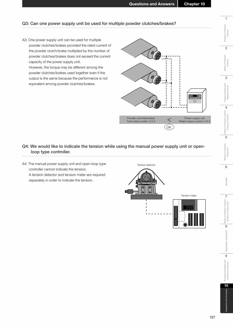
127
Chapter 10Questions and Answers
1
Out
line
of T
ensi
on
Con
trol
2
Bas
is o
f Ten
sion
C
ontr
ol
3
Torq
ue C
ontr
ol a
nd
Spe
ed C
ontr
ol
4
Type
s of
Ten
sion
Con
trol
(T
orqu
e C
ontr
ol)
5
Wha
t Is
a Te
nsio
n D
etec
tor?
6
Act
uato
r
7
Bas
is o
f Ten
sion
Con
trol
S
yste
m C
onst
ruct
ion
8A
pplic
atio
n Ex
ampl
es
9
Trou
ble
Exam
ples
and
C
orre
ctiv
e A
ctio
ns
10
Que
stio
ns a
nd A
nsw
ers
Q3: Can one power supply unit be used for multiple powder clutches/brakes?
A3: One power supply unit can be used for multiple powder clutches/brakes provided the rated current of the powder clutch/brake multiplied by the number of powder clutches/brakes does not exceed the current capacity of the power supply unit. However, the torque may be different among the powder clutches/brakes used together even if the output is the same because the performance is not equivalent among powder clutches/brakes.
Power supply unitRated output current: 3.8 A
Powder clutches/brakesTotal rated current: 3.0 A <
OK
Q4: We would like to indicate the tension while using the manual power supply unit or open-looptypecontroller.
A4: The manual power supply unit and open-loop type controller cannot indicate the tension.
A tension detector and tension meter are required separately in order to indicate the tension.
Tension detector
Tension meter

128
Chapter 10 Questions and Answers
1
Out
line
of T
ensi
on
Con
trol
2
Bas
is o
f Ten
sion
C
ontr
ol
3
Torq
ue C
ontr
ol a
nd
Spe
ed C
ontr
ol
4
Type
s of
Ten
sion
Con
trol
(T
orqu
e C
ontr
ol)
5
Wha
t Is
a Te
nsio
n D
etec
tor?
6
Act
uato
r
7
Bas
is o
f Ten
sion
Con
trol
S
yste
m C
onst
ruct
ion
8
App
licat
ion
Exam
ples
9
Trou
ble
Exam
ples
and
C
orre
ctiv
e A
ctio
ns
10
Que
stio
ns a
nd A
nsw
ers
Q5:Thelengthofthecable(7minthenon-explosion-proofspecifications,20mintheexplosion-proofspecifications)suppliedasanaccessoryofthetensiondetectorisinsufficient.Canitbeextended?
A5: An optional extension cable (50 m) is available. Contact your sales agent.
50 m
Q6: What is a hinge of the tension detector?
A6: A flat spring supported on only one side is incorporated in the tension detector, and its bend is detected. The supporting point of the flat spring is called a hinge. If the resultant force of the tension faces the hinge direction, the flat spring bends by less than the degree corresponding to the actual tension, and the accuracy of tension detection is poor. This should be considered when selecting the tension detector.
Flat spring
Hinge
Detection accuracy in accordancewith the tension direction
Good
Good
BadBad
A7: The pillow block mounting bolts may be interfering with the housing. As a countermeasure, use shorter bolts to prevent interference.
Q7: Why is the tension detector not displaced even when a load is applied?
Pillow blockmounting bolt
Tension detection roller
Pillow block
Long bolt
The bolt is interferingwith the housing.
Installation using the standard pillow block

129
Chapter 10Questions and Answers
1
Out
line
of T
ensi
on
Con
trol
2
Bas
is o
f Ten
sion
C
ontr
ol
3
Torq
ue C
ontr
ol a
nd
Spe
ed C
ontr
ol
4
Type
s of
Ten
sion
Con
trol
(T
orqu
e C
ontr
ol)
5
Wha
t Is
a Te
nsio
n D
etec
tor?
6
Act
uato
r
7
Bas
is o
f Ten
sion
Con
trol
S
yste
m C
onst
ruct
ion
8A
pplic
atio
n Ex
ampl
es
9
Trou
ble
Exam
ples
and
C
orre
ctiv
e A
ctio
ns
10
Que
stio
ns a
nd A
nsw
ers
A9: The material may have been slack when the machine was stopped. As a countermeasure, drive the winding motor in advance before driving the machine main motor so that the material is not slack when the tension controller is started.
A8: The mechanical loss may have some effect. As a countermeasure, it is necessary to reduce the mechanical loss. Major causes of mechanical loss are the sliding resistance of the bearing which supports the reel shaft and the gear installed between the reel shaft and the brake. The mechanical loss tends to increase with higher gear ratio. Because the mechanical loss is not constant but fluctuates, it may cause tension fluctuations and hunting. Hunting can occur easily in the low torque region (where the output voltage is low) because the reel shaft torque is affected considerably by the torque caused by the mechanical loss.
Q9: Why does the tension not increase immediately after the line driving is started in winding control using the powder clutch?
Q8:Whydotorquefluctuationsandhuntingoccur(especiallyinthelowtorqueregion)?
Main motor
Powder clutch
Windingmotor
Driven inadvance
Tension controller
Output
Main motor
Powder clutch
Windingmotor
Tension controller
Output
Powder brake
Reel diameterLargeSmall
Reel shafttorque
A + B: Reel shaft torque
Braking torque
Mechanical loss
A:Braking torque
B: Torque causedby mechanical loss
Tension controller
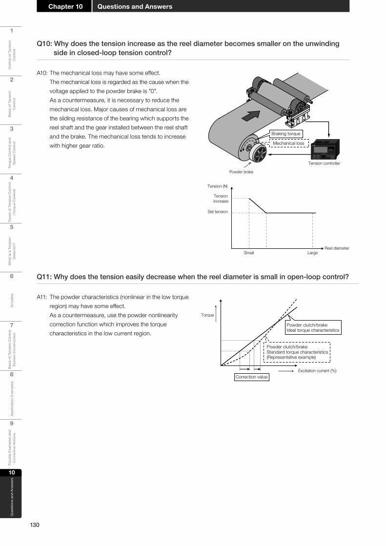
130
Chapter 10 Questions and Answers
1
Out
line
of T
ensi
on
Con
trol
2
Bas
is o
f Ten
sion
C
ontr
ol
3
Torq
ue C
ontr
ol a
nd
Spe
ed C
ontr
ol
4
Type
s of
Ten
sion
Con
trol
(T
orqu
e C
ontr
ol)
5
Wha
t Is
a Te
nsio
n D
etec
tor?
6
Act
uato
r
7
Bas
is o
f Ten
sion
Con
trol
S
yste
m C
onst
ruct
ion
8
App
licat
ion
Exam
ples
9
Trou
ble
Exam
ples
and
C
orre
ctiv
e A
ctio
ns
10
Que
stio
ns a
nd A
nsw
ers
A10: The mechanical loss may have some effect. The mechanical loss is regarded as the cause when the
voltage applied to the powder brake is "0". As a countermeasure, it is necessary to reduce the mechanical loss. Major causes of mechanical loss are the sliding resistance of the bearing which supports the reel shaft and the gear installed between the reel shaft and the brake. The mechanical loss tends to increase with higher gear ratio.
A11: The powder characteristics (nonlinear in the low torque region) may have some effect. As a countermeasure, use the powder nonlinearity correction function which improves the torque characteristics in the low current region.
Q10: Why does the tension increase as the reel diameter becomes smaller on the unwinding side in closed-loop tension control?
Q11: Why does the tension easily decrease when the reel diameter is small in open-loop control?
Excitation current (%)
Torque
Powder clutch/brakeStandard torque characteristics(Representative example)
Powder clutch/brakeIdeal torque characteristics
Correction value
Powder brake
Reel diameterLargeSmall
Tension (N)
Tensionincrease
Set tension
Braking torque
Mechanical loss
Tension controller
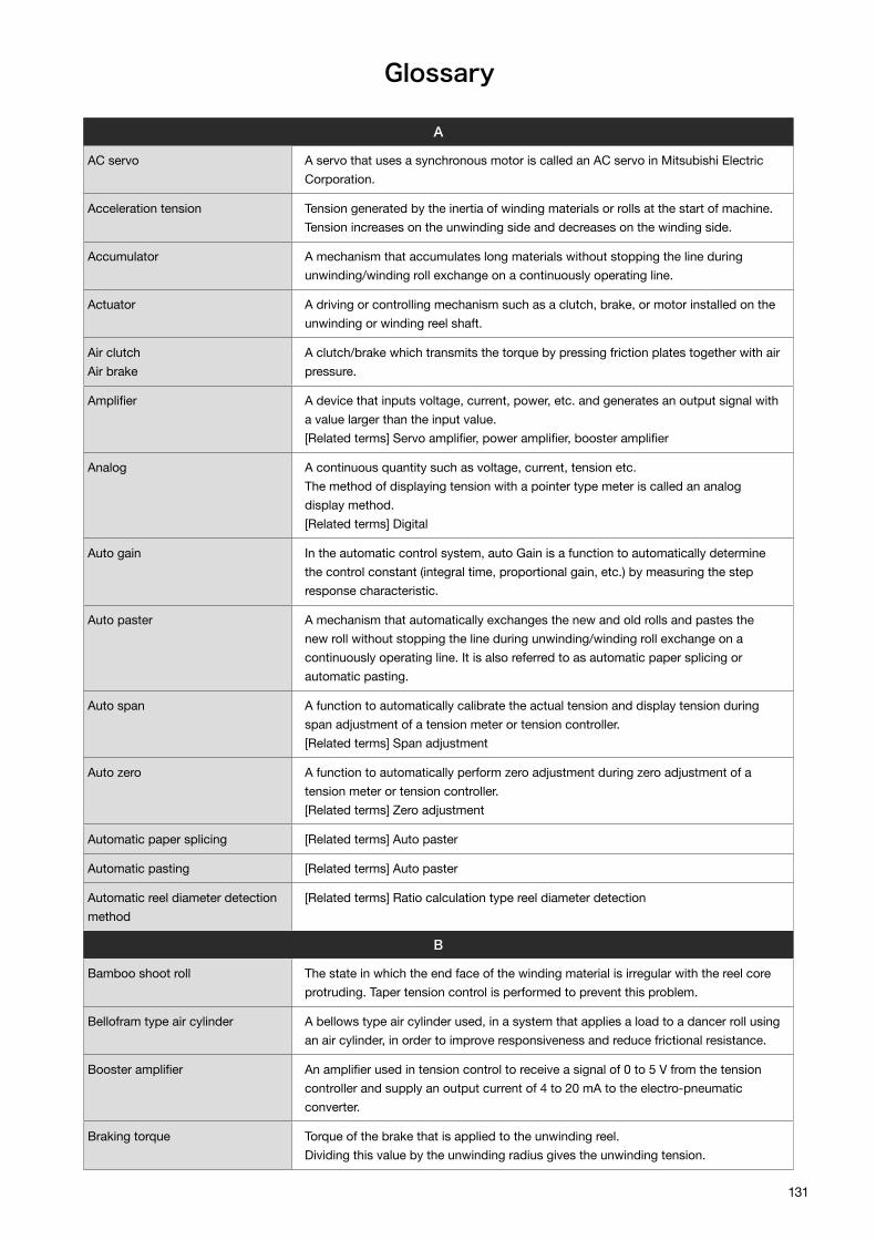
131
Glossary
A
AC servo A servo that uses a synchronous motor is called an AC servo in Mitsubishi Electric Corporation.
Acceleration tension Tension generated by the inertia of winding materials or rolls at the start of machine. Tension increases on the unwinding side and decreases on the winding side.
Accumulator A mechanism that accumulates long materials without stopping the line during unwinding/winding roll exchange on a continuously operating line.
Actuator A driving or controlling mechanism such as a clutch, brake, or motor installed on the unwinding or winding reel shaft.
Air clutchAir brake
A clutch/brake which transmits the torque by pressing friction plates together with air pressure.
Amplifier A device that inputs voltage, current, power, etc. and generates an output signal with a value larger than the input value.[Related terms] Servo amplifier, power amplifier, booster amplifier
Analog A continuous quantity such as voltage, current, tension etc.The method of displaying tension with a pointer type meter is called an analog display method.[Related terms] Digital
Auto gain In the automatic control system, auto Gain is a function to automatically determine the control constant (integral time, proportional gain, etc.) by measuring the step response characteristic.
Auto paster A mechanism that automatically exchanges the new and old rolls and pastes the new roll without stopping the line during unwinding/winding roll exchange on a continuously operating line. It is also referred to as automatic paper splicing or automatic pasting.
Auto span A function to automatically calibrate the actual tension and display tension during span adjustment of a tension meter or tension controller.[Related terms] Span adjustment
Auto zero A function to automatically perform zero adjustment during zero adjustment of a tension meter or tension controller.[Related terms] Zero adjustment
Automatic paper splicing [Related terms] Auto paster
Automatic pasting [Related terms] Auto paster
Automatic reel diameter detection method
[Related terms] Ratio calculation type reel diameter detection
B
Bamboo shoot roll The state in which the end face of the winding material is irregular with the reel core protruding. Taper tension control is performed to prevent this problem.
Bellofram type air cylinder A bellows type air cylinder used, in a system that applies a load to a dancer roll using an air cylinder, in order to improve responsiveness and reduce frictional resistance.
Booster amplifier An amplifier used in tension control to receive a signal of 0 to 5 V from the tension controller and supply an output current of 4 to 20 mA to the electro-pneumatic converter.
Braking torque Torque of the brake that is applied to the unwinding reel.Dividing this value by the unwinding radius gives the unwinding tension.

132
Broken line taper Taper tension control which changes the taper ratio in the intermediate reel diameter without using the same taper ratio from the initial diameter to the final diameter.[Related terms] Taper tension
C
Closed-loop control To automatically control the output according to the difference between the target value and detected value.This corresponds to a tension controller that uses a tension detector in combination.
Constant current control unit Regardless of fluctuations in power supply voltage or load resistance, this control unit produces variable constant output current.
Constant tension control Regardless of changes in reel diameter, unwinding/winding is controlled with a constant tension.
Constant torque control Regardless of changes in reel diameter, unwinding/winding is controlled with a constant torque. A type of taper tension control.
Constant voltage control unit Regardless of fluctuations in power supply voltage or load resistance, this control unit produces variable constant output voltage.
Control components Components such as a transformer, diode stack, sliding voltage regulator, adjustment resistor, protective resistor etc., which constitute a DC power supply for clutches and brakes.
Controller A control unit.Refers to a power amplifier, tension controller, or the like with respect to tension control.
Converting To apply various processing and treatment to long materials.The machines used for this purpose are called converting machines.
Corner diameter Reel diameter which becomes a corner point where the taper rate changes in the broken line taper.[Related terms] Broken line taper
D
Dancer roll A driven roll with a support shaft which can move up and down or right and left.In terms of the dancer roll, the tension of material is determined by the load applied to the roll support shaft.
Dead band In closed loop control that performs output control according to the deviation between the target value and detection value, correction control is not performed when the deviation is small in order to achieve stabilization. Dead band is a deviation band for achieving stabilization.[Related terms] Closed-loop control
Deceleration gain Control magnification for reducing tension fluctuation caused by reel inertia during deceleration of the machine.Example: In the case of the LE-40MTA-E type fully automatic tension controller, an output of 0 to 400% of the current output (below the rated output) can be generated.
Deceleration tension Tension generated by inertia of reels at deceleration of the machine.Tension decreases on the unwinding side and increases on the winding side.
Differential transformer Used to measure the displacement of the spring dancer roll to detect the tension, or to measure the movement of the touch lever to detect the reel diameter.A movable iron core is provided between the primary and secondary coils so that a secondary coil voltage corresponding to the iron core position can be obtained.[Related terms] Spring dancer roll, touch lever
Digital A method of handling values based on discrete quantities.[Related terms] Analog

133
Draw control To operate at a constant elongation rate (drawing rate) by providing multiple feed rolls and slightly increasing the peripheral speed of the rear stage.
Drive member Input-side rotating body of a clutch or brake.
Driven member Output-side rotating body of the clutch.
Driven roll A roll which is not driven by the motor.[Related terms] Guide roll
E
Electronic gear To compensate for the error between the gear ratio required in the system and the actual gear ratio of the machine by electronic circuit or arithmetic processing.
Electro-pneumatic converter Used to obtain air pressure proportional to the input electrical signal and to control air clutches and air brakes.Power supply unit: DC power supply with a built-in manual regulator used to excite clutches and brakes.
External taper tension control To control taper tension by using a reel diameter detection device.[Related terms] Taper tension, internal taper tension control
External tension meter Displays the tension signal received from the tension meter.Tension meters showing various full-scale tension scales are available.
F
Feed roll A driving roll to run long materials.The feed roll must have a structure which does not cause slippage between the roll and material. Also referred to as a nip roll or pinch roll.
Feedback In the case of tension detection, the detected value of tension is loaded into the control system in closed loop control.[Related terms] Closed-loop control
Fine displacement tension detector
Detects tension by measuring fine displacements (0 to ±200 μm) of leaf springs based on tension load with a high precision differential transformer.
G
Geared motor A motor integrated with a speed reducer.A servo motor with a speed reducer with a large deceleration ratio is not very suitable for torque control.
Guide roll A roll used for preventing horizontal deflection and a change in direction during material traveling. It is also referred to as a driven roll because it is not driven by a motor but is rotated by the traveling of material.[Related terms] Driven roll
H
Heat dissipation Heat generation per unit time caused by slipping.The heat dissipation P (W) of the clutch/brake is proportional to the product of the slip rotation speed Nr (r/min) and transmission torque T (Nm).P = 0.105 NrT (W)
Hunting Hunting phenomenon in feedback control.
I
Inertia compensation control Due to the inertia of the reel, the tension increases on the unwinding side and decreases on the winding side when the machine starts. Conversely, when the machine decelerates, the tension decreases on the unwinding side and increases on the winding side.In order to suppress such tension fluctuation, this control is performed to increase or decrease the braking torque and winding torque at the time of starting or stopping.

134
In-feed Between unwinding reel and feed roll.[Related terms] Feed-roll
In-feed roll Roll provided in in-feed.The in-feed roll is driven by a clutch, brake, servo motor, etc.As a result, the tension of the long material upstream of the processing machine can be controlled with high accuracy.[Related terms] In-feed
Integral time Even when the tension deviation is small, if it continues, the control output is changed to further lessen the tension deviation. The term refers to the integral time constant at this time.
Integrated thickness detection method
Determines the reel diameter by the product of the set value of material thickness and the amount of reel rotation.
Internal taper tension control To control taper tension without using a reel diameter detection device.[Related terms] Taper tension, external taper tension control
Inverter A device that implements variable-speed driving of a general-purpose induction motor by coaanverting commercial AC voltage to DC voltage and to variable frequency AC voltage.
L
Length measurement function Detection function of material travel length.The function can obtain advance notice signals and final signals of empty reels (unwinding) and full reels (winding).
Level meter Displays tension values in the form of a bar graph with LEDs arranged in a straight line.
Lifting roll A driven roll in the accumulator.The support shafts of a number of lifting rolls are moved up and down to accumulate or take out the materials.[Related terms] Accumulator, driven roll
Linear line taper To control the taper tension with a constant tension taper ratio from the initial diameter to the final diameter. (The taper ratio should be controlled constantly during control.)[Related terms] Taper tension
M
Mechanical loss correction To prevent any rolling resistance in the reel from affecting the control tension.
Multi-shaft distribution control In the simultaneous multi-shaft winding/unwinding mechanism, control output of each shaft should be distributed based on the signal of a single control unit.
N
New shaft preset In automatic paper splicing control, set the initial value of the torque required for the new shaft immediately after switching.[Related terms] Auto paster
Nip roll [Related terms] Feed-roll
Nonlinear correction To make correction between the input signal and output current to compensate for current vs. torque nonlinearity in the powder clutch/brake.
Numeric keypad A keypad having 10 numeric keys from 0 to 9. It is used for various numerical settings in digital control units.
O
Old shaft sudden stop The automatic paper splicing/unwinding mechanism suddenly stops the reel on the side where unwinding has been completed.For this purpose, some control units have a fixed power supply of short duration rating.

135
Open-loop control Control to keep the tension constant by controlling the reel torque by reel diameter detection.[Related terms] Closed-loop control
Out-feed Between the winding reel and the feed roll.
Out-feed roll Roll provided in out-feed.The out-feed roll is driven by a clutch, brake, servo motor, etc.As a result, the tension of the long material after processing can be controlled with high accuracy.[Related terms] Out-feed
P
Phase control One of the AC voltage control methods, which extracts a part of the AC waveform and controls the average voltage of the output while changing the current running time.
Pillow block Support of the bearing supporting tension detection roller.The height from the mounting surface to the support center is called the center height.
Pinch roll [Related terms] Feed-roll
Positive unwinding To drive the unwinding reel for initial paper feeding operation, or to accelerate the preparation reel (new shaft) during automatic paper splicing operation and drive the unwinding reel with a motor at the time of circumferential speed adjustment, etc.
Potentiometer Detects the rotation angle by applying a constant voltage between the fixed terminals of the variable resistor and measuring the potential of the sliding terminal.
Powder clutchPowder brake
An electromagnetic type clutch/brake which transmits torque by filling fine iron powder between the input rotating body and the output rotating body (or stationary body) and giving magnetism to it.
Power amplifier Generates 0 to rated output voltage and current for the powder clutch/brake in proportion to input signal voltage 0 to 5 V.
Predrive Preparatory operation performed in the automatic paper splicing device in order to adjust the peripheral speed of the preparatory reel to the line speed.
Press roll A roll used in a circumferential driving/braking type winding/unwinding device in order to keep the reel pressed against the under-roll.
Proportional gain The ratio of the direct response component of the control output with respect to the control deviation.
Proximity switch A non-contact type switch that operates when the detector approaches.It may be used as a rotation signal of a reel or feed roll.[Related terms] Feed-roll
Pulse generator The device that generates pulses to detect the rotation speed of the feed roll in a ratio calculation type reel diameter detection device.Also referred to as a rotary encoder.
R
Ratio calculatioan type reel diameter detection
A method of detecting the reel diameter by dividing the rotation speed of the feed roll by the rotation speed of the reel frame.
Reel shaft electronic gear Electronic gear correction with respect to reel shaft rotation detection pulse signal (reel shaft pulse).[Related terms] Electronic gear
Rotary encoder [Related terms] Pulse generator
Rotary joint A rotation mechanism for sending cooling water to the water-cooled powder clutch/brake provided on the turning arm for automatic paper splicing.

136
S
Safety barrier Connected between explosion-proof equipment and non-explosion-proof equipment to prevent an abnormal voltage generated in non-explosion-proof equipment installed in a general environment from entering a hazardous environment.
Semi-automatic reel diameter detection
[Related terms] Integrated thickness detection method
Sensitivity Proportional constant of deviation input to the integrating circuit.Hunting tends to occur when sensitivity is high, and the steady-state deviation increases when sensitivity is low.[Related terms] Hunting
Sensor Refers to a tension detector, proximity switch, pulse generator, and so on in tension control.
Servo amplifier The controller controls the servomotor through a servo amplifier. In tension control, a servo amplifier is connected between the tension controller and servomotor. In response to input signals of 0 to 5 V, the servomotor generates 0 to rated torque.[Related terms] Controller, servomotor
Servo motor A motor that can be freely drive-controlled based on the difference between the command signal and the feedback signal from the detector. It can perform position control, speed control, torque control, etc.
Sliding tension To prevent a sudden change of tension by gradually decreasing the actual command value even if the set value suddenly decreases.Such a gradual decline gradient can be adjusted.
Slip ring A conductive ring with a brush that contacts the rotating body for energizing.A slip ring is required when a powder clutch or powder brake is installed on the turning arm for automatic paper splicing.
Slip rotation speed Difference between the input rotation speed and the output rotation speed of the clutch. It is also the input rotation speed itself in terms of a brake.
Span adjustment To adjust the proportional constant so that the rated output signal and the full-scale display output signal of the meter can be obtained when the maximum input signal is given.
Spring dancer roll To give tension to the material by expansion and contraction of the spring provided on the dancer roll.[Related terms] Dancer roll
Stall torque A certain amount of torque which continues to be applied during startup of the machine or after completion of stop. No feedback control is performed during this time.[Related terms] Feedback
Start timer A timer used in tension control to set the time to switch to the automatic tension control mode after starting the machine. During this period, operation is performed with a predetermined torque (stall torque).
Stop bias In unwinding tension control, to apply a predetermined braking torque temporarily in order to prevent sag due to inertia during stop.
Stop gain Magnification of control output generated during operation of the stop timer after the machine stop operation is started.
Stop roll A roll which is provided at the entrance of the unwinding-side accumulator or the entrance of the winding-side accumulator to hold the material while exchanging reels.
Stop timer A timer used for tension control to set the time during which inertia compensation control (stop gain, stop bias correction) is performed at the time of stop.

137
T
Taper tension In the winding operation, tension is gradually reduced as the winding thickness.
Taper tension ratio Tapering ratio of tension.(Minimum diameter tension - maximum diameter tension)/minimum diameter tension
Tension control by torque control Tension control based on torque control, which controls the tension of the material by adjusting the rotation torque of the roll.
Tension meter Amplifies the weak signal (0 to ±150 mV) from the tension detector to obtain a tension signal output of 0 to 5 V and display its value on the meter.
Torque motor A specially designed AC squirrel cage motor, equipped with a cooling fan so that it can operate at an arbitrary rotational speed.The output torque can be changed by the applied voltage, but is decreased as the rotation speed increases.
Touch lever The moving angle of the roll in contact with the reel is detected by the motion of the lever to obtain a signal in proportion to the reel diameter.The movement of the lever is detected with the differential transformer, potentiometer or the like.
Transistor chopper Controls the average voltage applied to the load by controlling the ON/OFF ratio of the transistor connected in series with the load.The transistor chopper reduces the heat generation of the adjustment part compared to adjusting with a variable resistor or the like.
Transmission torque The torque transmitted from the input shaft of the clutch to the output shaft.It becomes equal to the control torque of the clutch when the clutch is slipping.
Turning arm A reel support for changing the positions of multiple unwinding or winding reels and carrying out the operation for switching to a new shaft.It is also called a turret arm.
Turret arm [Related terms] Turning arm
U
Under-roll A roll installed in the lower part of the reel, not to drive/brake the winding shaft/unwinding shaft, but to drive/brake the rolls that come in contact with the periphery of the reel.
W
Weight dancer Adds a load to the dancer roll to apply tension to the material.[Related terms] Dancer roll
Z
Zero adjustment Operation to adjust the position, where the tension detection roller's own weight is applied, to the 0 (zero) point.
Zero tension detection To detect the condition under which the tension becomes lower than the setting.
Other
% output meter When the output current to the powder clutch/brake is displayed, the rated current (or rated torque, rated voltage) of the load is regarded as 100%, which is made to correspond to the full scale of the 1 mA DC meter.
• Pressductor is either a registered trademark or a trademark of ABB AB.
• The company names, system names and product names mentioned in this document are either registered trademarks or trademarks of their respective companies.
• In some cases, trademark symbols such as 'TM' or '®' are not specified in this document.
Trademarks and registered trademarks

138
MEMO


All trademarks acknowledged.
http://Global.MitsubishiElectric.comHEAD OFFICE: TOKYO BLDG., 2-7-3, MARUNOUCHI, CHIYODA-KU, TOKYO 100-8310, JAPAN
Tension Control C
omplete G
uide
ELECTROMAGNETIC CLUTCHES AND BRAKES
TENSION CONTROLLER
Printed August 2019SH(NA)170011ENG-C 1908(MEE)