tension-weldfi strapping toolsusastrap.com/wp-content/themes/jcw/pdfs/signode_286139_vxlm... · 3...
TRANSCRIPT

VXL-2000-Z and VXM-2000-ZTENSION-WELD®
STRAPPING TOOLS
2
READ THESE INSTRUCTIONS CAREFULLY.
FAILURE TO FOLLOW THESE INSTRUCTIONS CAN RESULT IN SEVERE PERSONAL INJURY.
GENERAL SAFETY CONSIDERATIONS
1. STRAP BREAKAGE HAZARD.Improper operation of the tool or sharp corners on the load can result in strapbreakage during tensioning, which could result in the following:
! A sudden loss of balance causing you to fall.
! Both tool and strap flying violently towards your face.
Failure to place the strap properly around the load or an unstable or shifted load could result ina sudden loss of strap tension during tensioning. This could result in a sudden loss ofbalance causing you to fall.
Read the tool's operating instructions. If the load corners are sharp use edge protectors. Place the strap correctly around a properly positioned load.
! Positioning yourself in-line with the strap, during tensioning and sealing, can result insevere personal injury from flying strap or tool. When tensioning or sealing, positionyourself to one side of the strap and keep all bystanders away.
! Using strap not recommended for this tensioner can result in strap breakage duringtensioning. Use the correct Signode products for your application.
2. TRAINING.This tool must not be used by persons not properly trained in its use. Be certain that youreceive proper training from your employer. If you have any questions contact your SignodeRepresentative.
3. EYE INJURY HAZARD.Failure to wear safety glasses with side shields can result in severe eye injury orblindness. Always wear safety glasses with side shields which conform to ANSIStandard Z87.1 or EN 166.
4. FALL HAZARD.Maintaining improper footing and/or balance when operating the tool can cause you to fall. Donot use the tool when you are in an awkward position.
5. CUT HAZARD.Handling strap or sharp parts could result in cut hands or fingers. Wear protectivegloves.
6. TOOL CARE, MAINTENANCE & PARTS REPLACEMENT.
! Take good care of the tool. Inspect and clean it daily, lubricate it weekly and adjust whennecessary. Replace any worn or broken parts.
! ALWAYS disconnect the pneumatic connection to the tool when performing part removaland replacement procedures. NEVER connect a pneumatic source to a disassembled toolunless otherwise specified.
7. WORK AREA. Keep work areas uncluttered and well lighted.
3
Signode tools and machines are designed and warranted to work together with Signodestrapping and seals. Use of non-Signode strap, seals and/or manufactured or specifiedreplacement parts may result in strap breakage or joint separation while applying strappingto a load or during normal shipping and handling. This could result in severe personal injury.
Several types of strap can be used with this tool. Use the correct Signode products for yourapplication. If you need help contact your Signode Representative.
SAFETY PROCEDURES FOR TOOL OPERATION
1. Before using this tool, read its Operation and Safety instructions.
! Do not exceed the operating air pressures stated elsewhere in the manual.
! Use Signode's approved filter-regulator-lubricator unit (P-008559).
! Never operate a pneumatic tool with a bottled air or gas source.
! For tension adjustments, follow instructions in this manual. For all other adjustments,repairs or cleaning of the tool, disconnect air supply.
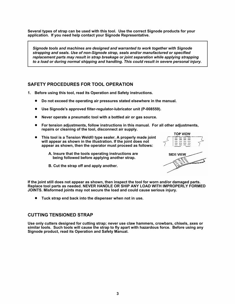
! This tool is a Tension Weld® type sealer. A properly made jointwill appear as shown in the illustration. If the joint does notappear as shown, then the operator must proceed as follows:
A. Insure that the tools operating instructions are being followed before applying another strap.
B. Cut the strap off and apply another.
If the joint still does not appear as shown, then inspect the tool for worn and/or damaged parts.Replace tool parts as needed. NEVER HANDLE OR SHIP ANY LOAD WITH IMPROPERLY FORMEDJOINTS. Misformed joints may not secure the load and could cause serious injury.
! Tuck strap end back into the dispenser when not in use.
CUTTING TENSIONED STRAP
Use only cutters designed for cutting strap; never use claw hammers, crowbars, chisels, axes orsimilar tools. Such tools will cause the strap to fly apart with hazardous force. Before using anySignode product, read its Operation and Safety Manual.
4
TABLE OF CONTENTS
General Safety Instructions 2
Specifications 4
Air Line Piping Installation 5
Operating Instructions 8
Adjustments 10
Parts Removal and Replacement 12
Air Logic and Diagram 20
Air Motor Identification 21
Parts List, Air Motors 22
Parts List, Tool 28
Troubleshooting 30
Maintenance 34
Tool Options 35
EU Declaration of Conformity 39
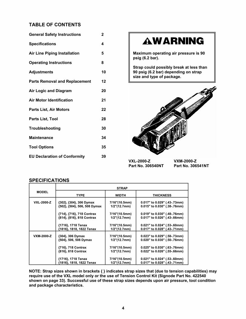
Maximum operating air pressure is 90 psig (6.2 bar).
Strap could possibly break at less than 90 psig (6.2 bar) depending on strap size and type of package.
VXL-2000-Z VXM-2000-ZPart No. 306540NT Part No. 306541NT
SPECIFICATIONS
MODELSTRAP
TYPE WIDTH THICKNESS
VXL-2000-Z {302}, {304}, 306 Dymax{502}, {504}, 506, 508 Dymax
{714}, {716}, 718 Contrax{814}, {816}, 818 Contrax
{1716}, 1718 Tenax{1816}, 1818, 1822 Tenax
7/16"(10.5mm)1/2"(12.7mm)
7/16"(10.5mm)1/2"(12.7mm)
7/16"(10.5mm)1/2"(12.7mm)
0.017" to 0.029" (.43-.73mm)0.015" to 0.030" (.38-.76mm)
0.019" to 0.030" (.48-.76mm)0.017" to 0.026" (.43-.66mm)
0.021" to 0.024" (.53-.60mm)0.017" to 0.028" (.43-.71mm)
VXM-2000-Z {304}, 306 Dymax{504}, 506, 508 Dymax
{716}, 718 Contrax{816}, 818 Contrax
{1716}, 1718 Tenax{1816}, 1818, 1822 Tenax
7/16"(10.5mm)1/2"(12.7mm)
7/16"(10.5mm)1/2"(12.7mm)
7/16"(10.5mm)1/2"(12.7mm)
0.023" to 0.029" (.58-.73mm)0.020" to 0.030" (.50-.76mm)
0.025" to 0.030" (.63-.76mm)0.022" to 0.026" (.55-.66mm)
0.021" to 0.024" (.53-.60mm)0.017" to 0.028" (.43-.71mm)
NOTE: Strap sizes shown in brackets { } indicates strap sizes that (due to tension capabilities) mayrequire use of the VXL model only or the use of Tension Control Kit (Signode Part No. 422540shown on page 33). Successful use of these strap sizes depends upon air pressure, tool conditionand package characteristics.
5
PNEUMATIC INFORMATION
AIR PRESSURE REQUIREMENTS
The VXL/VXM tools are designed to operate at air pressures ranging between 70 and 90 psig (4.8 -6.2 Bar). Operating these tools outside this pressure range could result in strap breakage due toover tensioning or poor quality welds.
AIR PRESSURE VS. PERFORMANCE
The air pressure supplied to the VXL/VXM tools must be a minimum of 70 psig (4.8 Bar) If the airsupply pressure can be adjusted within a range from 70 psi to 90 psi (4.8 - 6.2 Bar) the tool'sperformance can be fine tuned to a particular application or operation preferences. Raising theVXL/VXM air supply pressure to the tool will directly alter the rate at which the tool will take-up thestrap slack and the strap tension. Increasing or decreasing the VXL/VXM air supply within thesuggested 70 to 90 psig (4.8-6.2 Bar) range will not seriously affect the actual welding portion ofthe strap cycle.
After an initial "Break-In" period, the air motor may become more powerful. If the tool'sperformance is effected by this increase in performnace, reduce the air pressure at the regulatoras required (but not below 70 psig).
AIR SUPPLY INSTALLATION
If compressor has a good dryer unit, use black pickled pipe. When a dryer unit is not installed, usegalvanized or copper pipe. To perform reliably, a pneumatic tool requires a continuous source ofclean, water-free air at adequate pressure.
Never operate this tool using a bottled air or gas source.Bottled air/gas sources do not provide consistant operating pressure.
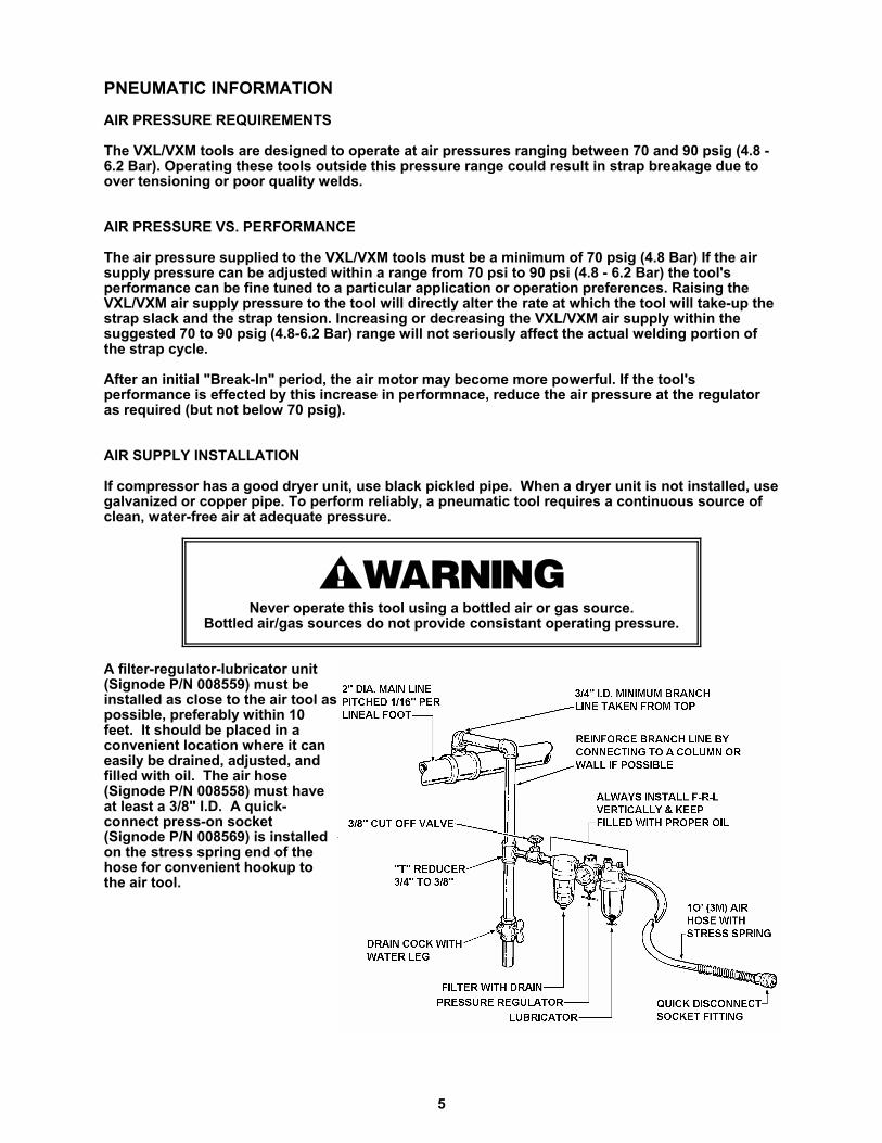
A filter-regulator-lubricator unit(Signode P/N 008559) must beinstalled as close to the air tool aspossible, preferably within 10feet. It should be placed in aconvenient location where it caneasily be drained, adjusted, andfilled with oil. The air hose(Signode P/N 008558) must haveat least a 3/8" I.D. A quick-connect press-on socket(Signode P/N 008569) is installedon the stress spring end of thehose for convenient hookup tothe air tool.
6
PNEUMATIC INFORMATION, Continued
Filter and lubricator bowls are made of polycarbonate material. Do not install where bowls may beexposed to materials incompatible with polycarbonate. Certain oils, solvents, and chemicals ortheir fumes can weaken these bowls and possibly cause them to burst. Clean only with warmwater. A cut-off valve placed ahead of the filter will be useful when cleaning the filter orreplenishing the lubricator.
MOISTURE
Moisture is always present in air lines due to condensation within the lines as the air cools. Stepsmust be taken to remove this moisture and to keep it from the air tool. This is because water tendsto wash away lubricants and cause corrosion, sticking and failure of internal parts.
The main line should be pitched so the far end terminates in a water leg. Branch lines are takenfrom the top of the main, never off the bottom. Every branch should have a water leg at its lowestpoint, with a drain cock which is drained daily.
If these precautions are taken and water is still present, an after cooler and a moisture separatorare required between the compressor and the air receiver tank. A large air line separator can beinstalled in the air tool line, but precautions must be taken to insure that it will be drained daily,before the air tool is operated.
Water in air lines is a constant threat to the proper operation of air tools. Even near freezingoperating conditions, a good refrigerant type dryer is essential. A good dryer will remove 95% ormore of water right at the compressor. The remaining moisture is removed at the water leg in thepiping system or in the filter (Signode Part No. 008559).
NOTE: Additional information is available in the Signode publication, "Air Supply Manual" (E-186038). If you have any questions, contact your local Signode Representative.
LUBRICATION
The air motor must be properly lubricated. This is achieved by keeping the air line lubricator filledwith oil and correctly adjusted. Without proper lubrication, the motor will become sticky and thetool will give low and erratic tension and be difficult to release from the strap.
Install the lubricator as close to the air tool as possible. The arrow on the lubricator's top surfacemust point in the direction of air flow. For proper operation, oil must drop through the lubricatorsight glass at a rate of 1 to 4 drops per minute. This rate is checked while the air tool is runningfree. Only 20% of this oil is actually delivered to the tool. The remaining oil drops back into the oilreservoir. The unit is factory set and should require no adjustment. If an adjustment is required,the adjusting screw on top of the lubricator may be turned as marked to reduce or increase theflow of oil.
The correct grade of oil must be used in the lubricator; too heavy an oil will not provide sufficientlubrication and will cause sticking and sluggish operation of the air tool. Recommended oils areany good grade of rust and oxidation inhibiting oil with a viscosity of 80-120 S.U.S. at 100 degreesFahrenheit. (0.15 to 0.25 cm2 /sec. at 38 degrees Celsius), such as:
Non Fluid Oil Co., grade #LS-1236 Signode oil - Part No. 008556
If necessary, use SAE #5 or SAE #10 non-detergent, cut 1 to 1 with kerosene.
NOTE: Some oils contain anti-wear additives which may disable the air motor. Be certain to userecommended oil.
Several drops of lubricator oil added to the inlet of the air motor or into the air line each day willhelp insure good operation. A noticeable reduction of air motor performance can usually becorrected by squirting a few drops of oil into the air line.
7
STRAP TENSION
Strap tension is controlled by air pressure. Adjust the pressure regulator, within a range of 70 - 90psig (4.8-6.2 bar), to provide the desired tension. Once the regulator is set the tension will beuniform on all straps, provided the operator allows the air motor to stall. The air pressure gaugemust be accurate. Confirm calibration by comparing it to a master gauge.
The VXL-2000Z tool is factory tested to ensure that at least 90 lbs. (400N) of tension is drawn at 90psig (6.2 bar) and the VXM-2000Z tool is factory tested to ensure that at least 140 lbs. (621 N) oftension is drawn at 90 psig (6.2 bar).
Review the instructions on page 10 of this manual for information on how to adjust strap tension.
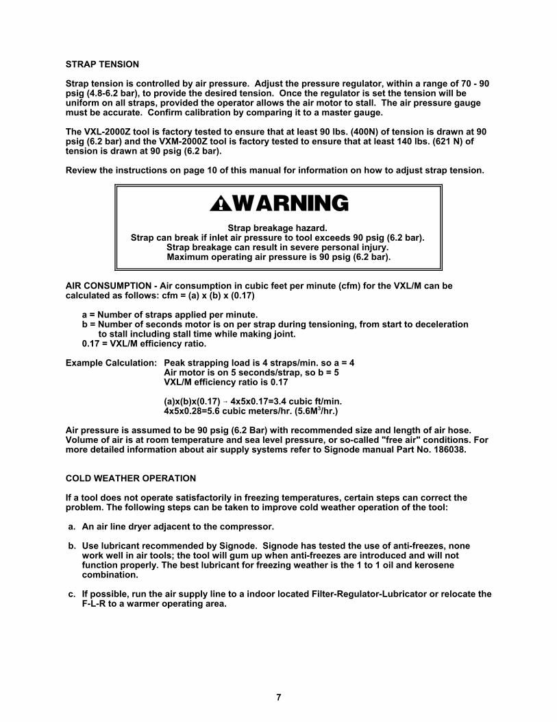
Strap breakage hazard. Strap can break if inlet air pressure to tool exceeds 90 psig (6.2 bar).
Strap breakage can result in severe personal injury. Maximum operating air pressure is 90 psig (6.2 bar).
AIR CONSUMPTION - Air consumption in cubic feet per minute (cfm) for the VXL/M can becalculated as follows: cfm = (a) x (b) x (0.17)
a = Number of straps applied per minute.b = Number of seconds motor is on per strap during tensioning, from start to deceleration
to stall including stall time while making joint.0.17 = VXL/M efficiency ratio.
Example Calculation: Peak strapping load is 4 straps/min. so a = 4Air motor is on 5 seconds/strap, so b = 5 VXL/M efficiency ratio is 0.17
(a)x(b)x(0.17) 6 4x5x0.17=3.4 cubic ft/min.4x5x0.28=5.6 cubic meters/hr. (5.6M3/hr.)
Air pressure is assumed to be 90 psig (6.2 Bar) with recommended size and length of air hose.Volume of air is at room temperature and sea level pressure, or so-called "free air" conditions. Formore detailed information about air supply systems refer to Signode manual Part No. 186038.
COLD WEATHER OPERATION
If a tool does not operate satisfactorily in freezing temperatures, certain steps can correct theproblem. The following steps can be taken to improve cold weather operation of the tool:
a. An air line dryer adjacent to the compressor.
b. Use lubricant recommended by Signode. Signode has tested the use of anti-freezes, nonework well in air tools; the tool will gum up when anti-freezes are introduced and will notfunction properly. The best lubricant for freezing weather is the 1 to 1 oil and kerosenecombination.
c. If possible, run the air supply line to a indoor located Filter-Regulator-Lubricator or relocate theF-L-R to a warmer operating area.
8
OPERATING INSTRUCTIONS
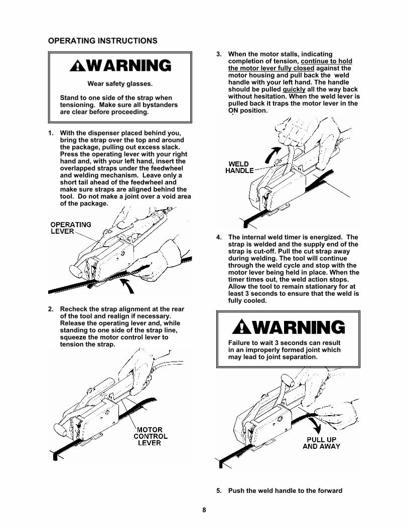
Wear safety glasses.
Stand to one side of the strap whentensioning. Make sure all bystandersare clear before proceeding.
1. With the dispenser placed behind you,bring the strap over the top and aroundthe package, pulling out excess slack. Press the operating lever with your righthand and, with your left hand, insert the overlapped straps under the feedwheeland welding mechanism. Leave only ashort tail ahead of the feedwheel andmake sure straps are aligned behind thetool. Do not make a joint over a void areaof the package.
2. Recheck the strap alignment at the rearof the tool and realign if necessary. Release the operating lever and, whilestanding to one side of the strap line, squeeze the motor control lever totension the strap.
3. When the motor stalls, indicatingcompletion of tension, continue to holdthe motor lever fully closed against themotor housing and pull back the weldhandle with your left hand. The handleshould be pulled quickly all the way backwithout hesitation. When the weld lever ispulled back it traps the motor lever in theON position.
4. The internal weld timer is energized. Thestrap is welded and the supply end of thestrap is cut-off. Pull the cut strap awayduring welding. The tool will continuethrough the weld cycle and stop with themotor lever being held in place. When thetimer times out, the weld action stops. Allow the tool to remain stationary for atleast 3 seconds to ensure that the weld isfully cooled.
Failure to wait 3 seconds can resultin an improperly formed joint whichmay lead to joint separation.
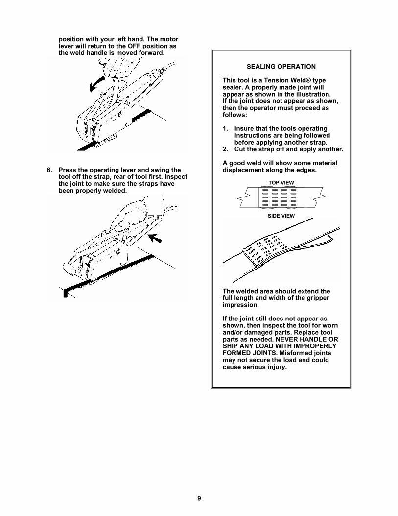
5. Push the weld handle to the forward
9
position with your left hand. The motorlever will return to the OFF position asthe weld handle is moved forward.
6. Press the operating lever and swing thetool off the strap, rear of tool first. Inspectthe joint to make sure the straps havebeen properly welded.
SEALING OPERATION
This tool is a Tension Weld® type sealer. A properly made joint willappear as shown in the illustration. If the joint does not appear as shown,then the operator must proceed asfollows:
1. Insure that the tools operatinginstructions are being followedbefore applying another strap.
2. Cut the strap off and apply another.
A good weld will show some materialdisplacement along the edges.
TOP VIEW
SIDE VIEW
The welded area should extend thefull length and width of the gripperimpression.
If the joint still does not appear asshown, then inspect the tool for wornand/or damaged parts. Replace tool parts as needed. NEVER HANDLE ORSHIP ANY LOAD WITH IMPROPERLYFORMED JOINTS. Misformed joints may not secure the load and couldcause serious injury.
10
TOOL ADJUSTMENTS
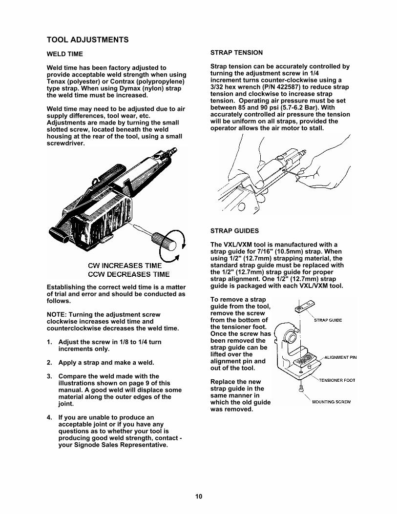
WELD TIME
Weld time has been factory adjusted toprovide acceptable weld strength when usingTenax (polyester) or Contrax (polypropylene)type strap. When using Dymax (nylon) strapthe weld time must be increased.
Weld time may need to be adjusted due to airsupply differences, tool wear, etc.Adjustments are made by turning the smallslotted screw, located beneath the weldhousing at the rear of the tool, using a smallscrewdriver.
Establishing the correct weld time is a matterof trial and error and should be conducted asfollows.
NOTE: Turning the adjustment screwclockwise increases weld time andcounterclockwise decreases the weld time.
1. Adjust the screw in 1/8 to 1/4 turnincrements only.
2. Apply a strap and make a weld.
3. Compare the weld made with theillustrations shown on page 9 of thismanual. A good weld will displace somematerial along the outer edges of thejoint.
4. If you are unable to produce anacceptable joint or if you have anyquestions as to whether your tool isproducing good weld strength, contact -your Signode Sales Representative.
STRAP TENSION
Strap tension can be accurately controlled byturning the adjustment screw in 1/4increment turns counter-clockwise using a3/32 hex wrench (P/N 422587) to reduce straptension and clockwise to increase straptension. Operating air pressure must be setbetween 85 and 90 psi (5.7-6.2 Bar). Withaccurately controlled air pressure the tensionwill be uniform on all straps, provided theoperator allows the air motor to stall.
STRAP GUIDES
The VXL/VXM tool is manufactured with astrap guide for 7/16" (10.5mm) strap. Whenusing 1/2" (12.7mm) strapping material, thestandard strap guide must be replaced withthe 1/2" (12.7mm) strap guide for properstrap alignment. One 1/2" (12.7mm) strapguide is packaged with each VXL/VXM tool.
To remove a strapguide from the tool, remove the screwfrom the bottom ofthe tensioner foot.Once the screw hasbeen removed thestrap guide can belifted over thealignment pin andout of the tool.
Replace the newstrap guide in thesame manner inwhich the old guidewas removed.
11
CUTTER ADJUSTMENTS
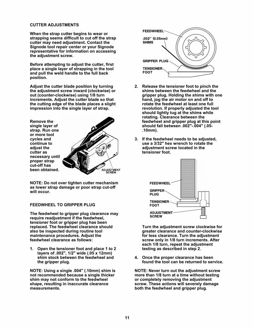
When the strap cutter begins to wear orstrapping seems difficult to cut off the strapcutter may need adjustment. Contact theSignode tool repair center or your Signoderepresentative for information on accessingthe adjustment screw.
Before attempting to adjust the cutter, firstplace a single layer of strapping in the tooland pull the weld handle to the full backposition.
Adjust the cutter blade position by turningthe adjustment screw inward (clockwise) orout (counter-clockwise) using 1/8 turnincrements. Adjust the cutter blade so thatthe cutting edge of the blade places a slightimpression into the single layer of strap.
Remove thesingle layer ofstrap. Run oneor more toolcycles andcontinue toadjust thecutter asnecessary untilproper strapcut-off hasbeen obtained.
NOTE: Do not over tighten cutter mechanismas lower strap damage or poor strap cut-offwill occur.
FEEDWHEEL TO GRIPPER PLUG
The feedwheel to gripper plug clearance mayrequire readjustment if the feedwheel,tensioner foot or gripper plug has beenreplaced. The feedwheel clearance shouldalso be inspected during routine toolmaintenance procedures. Adjust thefeedwheel clearance as follows:
1. Open the tensioner foot and place 1 to 2layers of .002", 1/2" wide (.05 x 12mm)shim stock between the feedwheel andthe gripper plug.
NOTE: Using a single .004" (.10mm) shim isnot recommended because a single thickershim may not conform to the feedwheelshape, resulting in inaccurate clearancemeasurements.
2. Release the tensioner foot to pinch theshims between the feedwheel and thegripper plug. Holding the shims with onehand, jog the air motor on and off torotate the feedwheel at least one fullrevolution. If properly adjusted the toolshould lightly tug at the shims whilerotating. Clearance between thefeedwheel and gripper plug at this pointshould fall between .002"-.004" (.05-.10mm).
3. If the feedwheel needs to be adjusted,use a 3/32" hex wrench to rotate theadjustment screw located in thetensioner foot.
Turn the adjustment screw clockwise forgreater clearance and counter-clockwisefor less clearance. Turn the adjustmentscrew only in 1/8 turn increments. Aftereach 1/8 turn, repeat the adjustmenttesting as described in step 2.
4. Once the proper clearance has beenfound the tool can be returned to service.
NOTE: Never turn out the adjustment screwmore than 1/8 turn at a time without testingor completely removing the adjustmentscrew. These actions will severely damageboth the feedwheel and gripper plug.
12
PARTS REMOVAL & REPLACEMENT
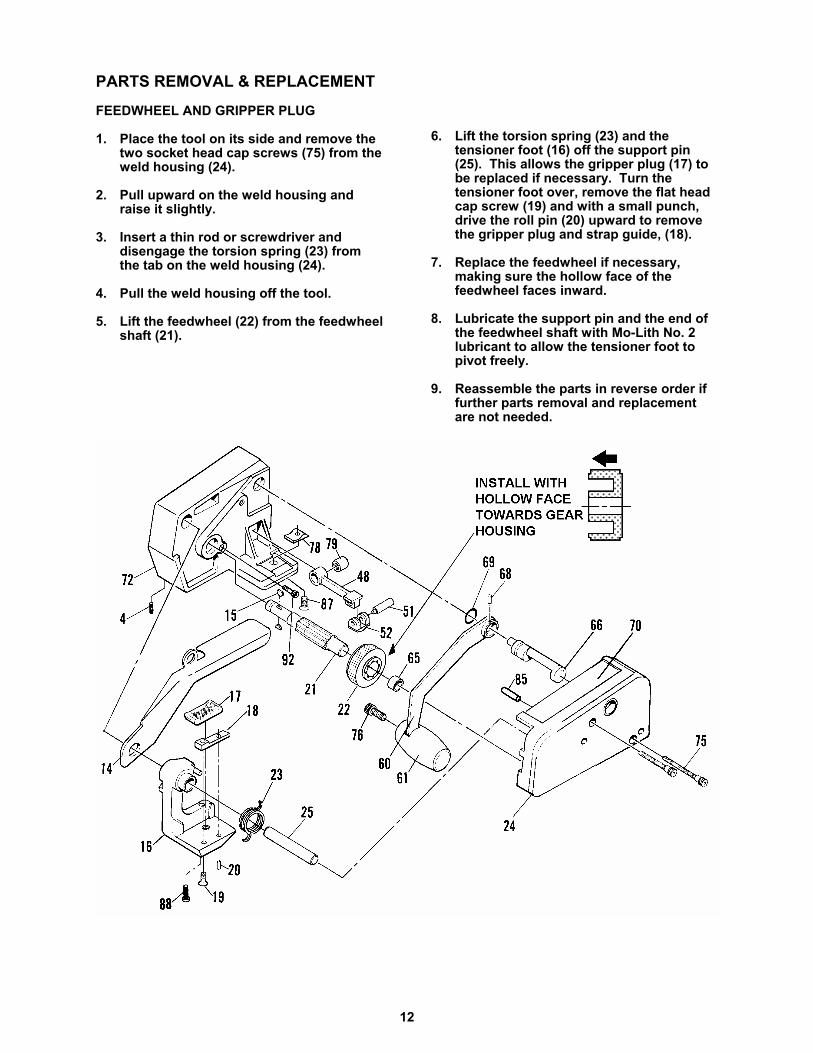
FEEDWHEEL AND GRIPPER PLUG
1. Place the tool on its side and remove thetwo socket head cap screws (75) from theweld housing (24).
2. Pull upward on the weld housing andraise it slightly.
3. Insert a thin rod or screwdriver anddisengage the torsion spring (23) fromthe tab on the weld housing (24).
4. Pull the weld housing off the tool.
5. Lift the feedwheel (22) from the feedwheelshaft (21).
6. Lift the torsion spring (23) and thetensioner foot (16) off the support pin(25). This allows the gripper plug (17) tobe replaced if necessary. Turn thetensioner foot over, remove the flat headcap screw (19) and with a small punch,drive the roll pin (20) upward to removethe gripper plug and strap guide, (18).
7. Replace the feedwheel if necessary,making sure the hollow face of thefeedwheel faces inward.
8. Lubricate the support pin and the end ofthe feedwheel shaft with Mo-Lith No. 2lubricant to allow the tensioner foot topivot freely.
9. Reassemble the parts in reverse order iffurther parts removal and replacementare not needed.
13
CUTTER BLADE
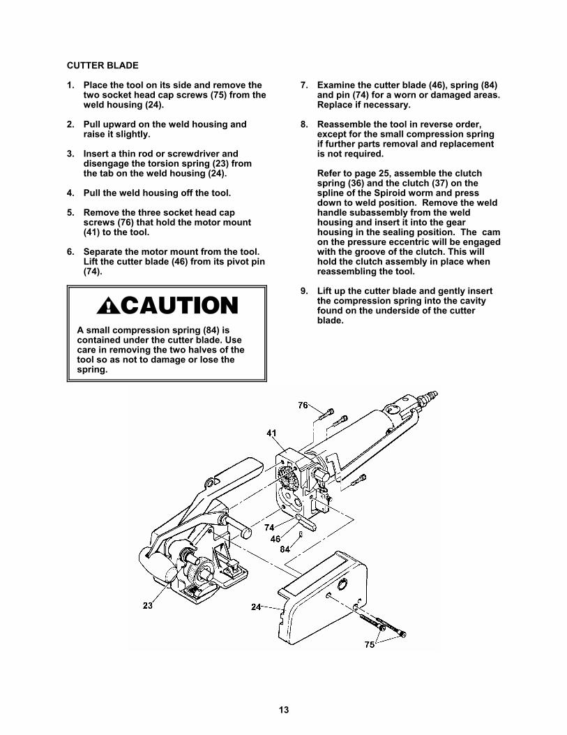
1. Place the tool on its side and remove thetwo socket head cap screws (75) from theweld housing (24).
2. Pull upward on the weld housing andraise it slightly.
3. Insert a thin rod or screwdriver anddisengage the torsion spring (23) fromthe tab on the weld housing (24).
4. Pull the weld housing off the tool.
5. Remove the three socket head capscrews (76) that hold the motor mount(41) to the tool.
6. Separate the motor mount from the tool.Lift the cutter blade (46) from its pivot pin(74).
A small compression spring (84) is contained under the cutter blade. Use care in removing the two halves of the tool so as not to damage or lose the spring.
7. Examine the cutter blade (46), spring (84)and pin (74) for a worn or damaged areas.Replace if necessary.
8. Reassemble the tool in reverse order,except for the small compression springif further parts removal and replacementis not required.
Refer to page 25, assemble the clutchspring (36) and the clutch (37) on thespline of the Spiroid worm and pressdown to weld position. Remove the weldhandle subassembly from the weldhousing and insert it into the gearhousing in the sealing position. The camon the pressure eccentric will be engagedwith the groove of the clutch. This willhold the clutch assembly in place whenreassembling the tool.
9. Lift up the cutter blade and gently insertthe compression spring into the cavityfound on the underside of the cutterblade.

14
WELDING MECHANISM & DRIVE GEARS
1. Remove the idler gear (27) from the pin(30) and examine both parts for wear.
2. Remove the eccentric shaft (26) andexamine it for wear.
3. Lift the slider link (48) from the gear
housing (72). Examine the teeth on theupper gripper (52) for wear. The uppergripper can be replaced by removing thepin (51).
4. Examine the teeth of the lower gripper(78). If the part is to be replaced, it maybe removed by first removing themounting screw (87) from underneath,then punching it out from underneaththrough the two holes.
When reinstalling a lower gripper, useLoctite "380 Black Max" (Signode PartNo. 274111) or an equivalent instantadhesive to ensure the lower gripper willbe held securely. Note that matingsurfaces must be free of dirt and grease.
NOTE: When using 380 Black Max adhesive,directly follow the manufacturers cleaningand preparation instructions.
5. Remove th needle bearing (29) from thehousing by threading a 1/4 x 20 screwthrough the bearing into spacer (86) referto Figure �C� on the following page.Clamp the screw head in a vise andlightly tap the casting to extract thebearing. If bearing removal becomesdifficult use the detailed instructions onthe following page.
15
FIGURE-A
FIGURE-B
FIGURE-C
FIGURE-D
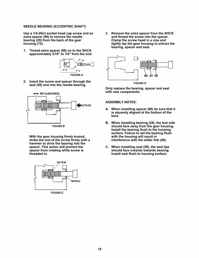
NEEDLE BEARING (ECCENTRIC SHAFT)
Use a 1/4-20x3 socket head cap screw and anextra spacer (86) to remove the needlebearing (29) from the back of the gearhousing (72).
1. Thread extra spacer (86) on to the SHCSapproximately 3/16" to 1/4" from the end.
2. Insert the screw and spacer through theseal (58) and into the needle bearing.
With the gear housing firmly braced,strike the end of the screw firmly with ahammer to drive the bearing into thespacer. This action will prevent thespacer from rotating while screw isthreaded in.
3. Remove the extra spacer from the SHCSand thread the screw into the spacer.Clamp the screw head in a vise andlightly tap the gear housing to extract thebearing, spacer and seal.
Only replace the bearing, spacer and sealwith new components.
ASSEMBLY NOTES:
A. When installing spacer (86) be sure that itis squarely aligned at the bottom of thebore.
B. When installing bearing (29), the text sideshould face away from the gear housing.Install the bearing flush to the housingsurface. Failure to set the bearing flushwith the housing will result ininterference with the slider link (48).
C. When installing seal (58), the seal lipsshould face inwards towards bearing.Install seal flush to housing surface.
16
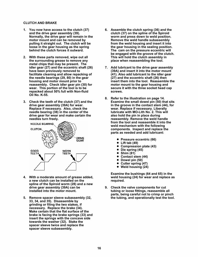
CLUTCH AND BRAKE
1. You now have access to the clutch (37)and the drive gear assembly (39). Normally, the drive gear will remain in themotor mount and can be removed bypulling it straight out. The clutch will beloose in the gear housing as the springbehind the clutch forces it outward.
2. With these parts removed, wipe out allthe surrounding grease to remove anymetal chips that may be present. Theidler gear (27) and the eccentric shaft (26)have been previously removed tofacilitate cleaning and allow repacking ofthe needle bearings (29, 80) in the gearhousing and motor mount prior toreassembly. Check idler gear pin (30) forwear. This portion of the tool is to berepacked about 50% full with Non-fluidOil No. K-55.
3. Check the teeth of the clutch (37) and thedrive gear assembly (39A) for wear. Replace if necessary. Also, check theneedle bearing (38) in the center of thedrive gear for wear and make certain theneedles turn freely.
4. With a moderate amount of grease added,a new clutch can be installed on thespline of the Spiroid worm (28) and a newdrive gear assembly (39A) can beinstalled into the motor mount.
5. Remove spacer sleeve subassembly (32,33, 34, and 35). Disassemble by grinding or filing the two stakes, ifnecessary. Replace the brake (34). Make certain that the flat surface of thebrake is facing the brake springs (33) andinsert the springs with the concave sidetowards the washer (32). Stake thespacer sleeve twice and replace thespacer sleeve subassembly.
6. Assemble the clutch spring (36) and theclutch (37) on the spline of the Spiroidworm and press down to weld position. Remove the weld handle subassemblyfrom the weld housing and insert it intothe gear housing in the sealing position. The cam on the pressure eccentric willbe engaged with the groove of the clutch.This will hold the clutch assembly inplace when reassembling the tool.
7. Add lubricant to the drive gear assembly(39A) and insert it into the motor mount(41). Also add lubricant to the idler gear(27) and the eccentric shaft (26) theninsert them into the tool. Reassemble themotor mount to the gear housing andsecure it with the three socket head capscrews.
8. Refer to the illustration on page 14.Examine the small dowel pin (50) that sitsin the groove in the contact stem (44), forwear. Replace if necessary. Liberallylubricate with MO-Lith No. 2. This willalso hold the pin in place duringreassembly. Remove the weld handlefrom the tool and reassemble it into theweld mechanism with the followingcomponents. Inspect and replace theparts as needed and add lubricant:
! Pressure eccentric (66)! Lift tab (49) ! Compression plate (43)! Die spring (45)! Shim (81)! Contact stem (44)! Dowel pin (50)! Cutter spring (47)! Weld housing (24)
Examine the bushings (64 and 65) in theweld housing (24) for wear and replace asrequired.
9. Check the valve components for cuttubing or loose fittings, reassemble allparts, being careful not to crimp or pinchthe tubing, and operationally test the tool.
17
AIR MOTOR
This tool is manufactured with one of twoavailable air motors. Inspect the air motorhousing to determine which specific airmotor instructions to follow. The two motorsavailable for this tool are part number 422550and 423150.
These instructions also apply to the olderVXL/VXM air motor 273830 (20R38V).
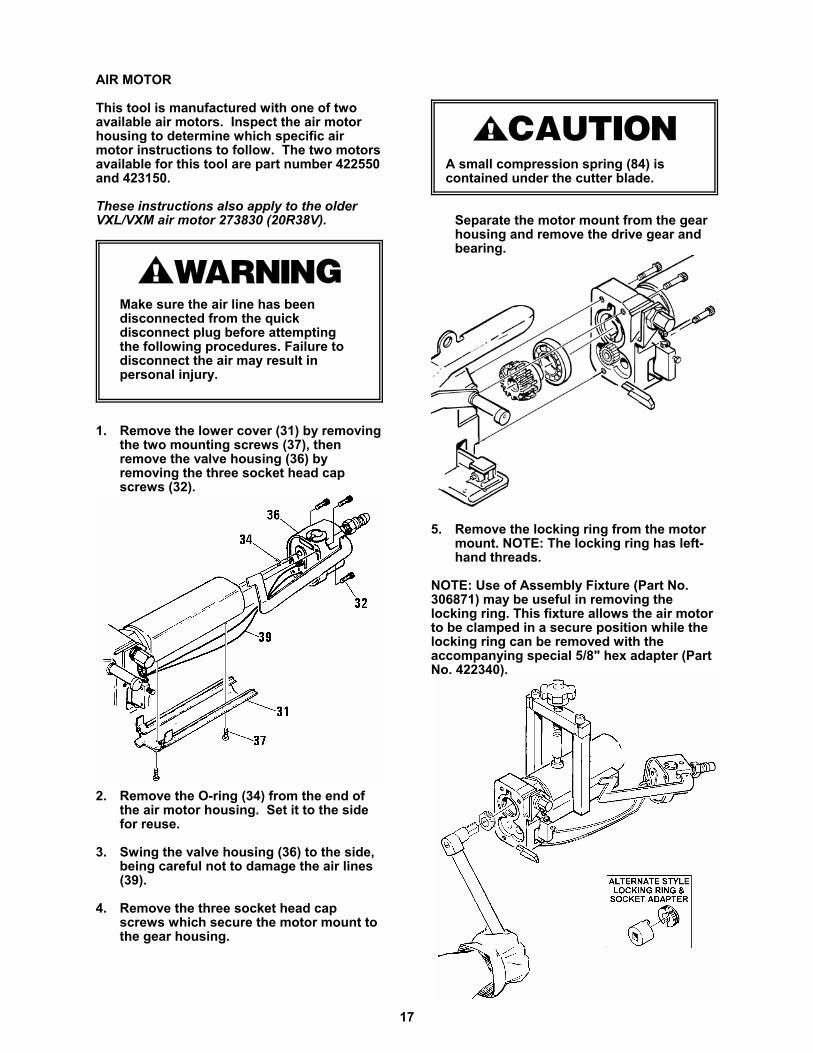
Make sure the air line has beendisconnected from the quick disconnect plug before attempting the following procedures. Failure todisconnect the air may result in personal injury.
1. Remove the lower cover (31) by removingthe two mounting screws (37), thenremove the valve housing (36) byremoving the three socket head capscrews (32).
2. Remove the O-ring (34) from the end ofthe air motor housing. Set it to the sidefor reuse.
3. Swing the valve housing (36) to the side,being careful not to damage the air lines(39).
4. Remove the three socket head capscrews which secure the motor mount tothe gear housing.
A small compression spring (84) is contained under the cutter blade.
Separate the motor mount from the gearhousing and remove the drive gear andbearing.
5. Remove the locking ring from the motormount. NOTE: The locking ring has left-hand threads.
NOTE: Use of Assembly Fixture (Part No.306871) may be useful in removing thelocking ring. This fixture allows the air motorto be clamped in a secure position while thelocking ring can be removed with theaccompanying special 5/8" hex adapter (PartNo. 422340).
18
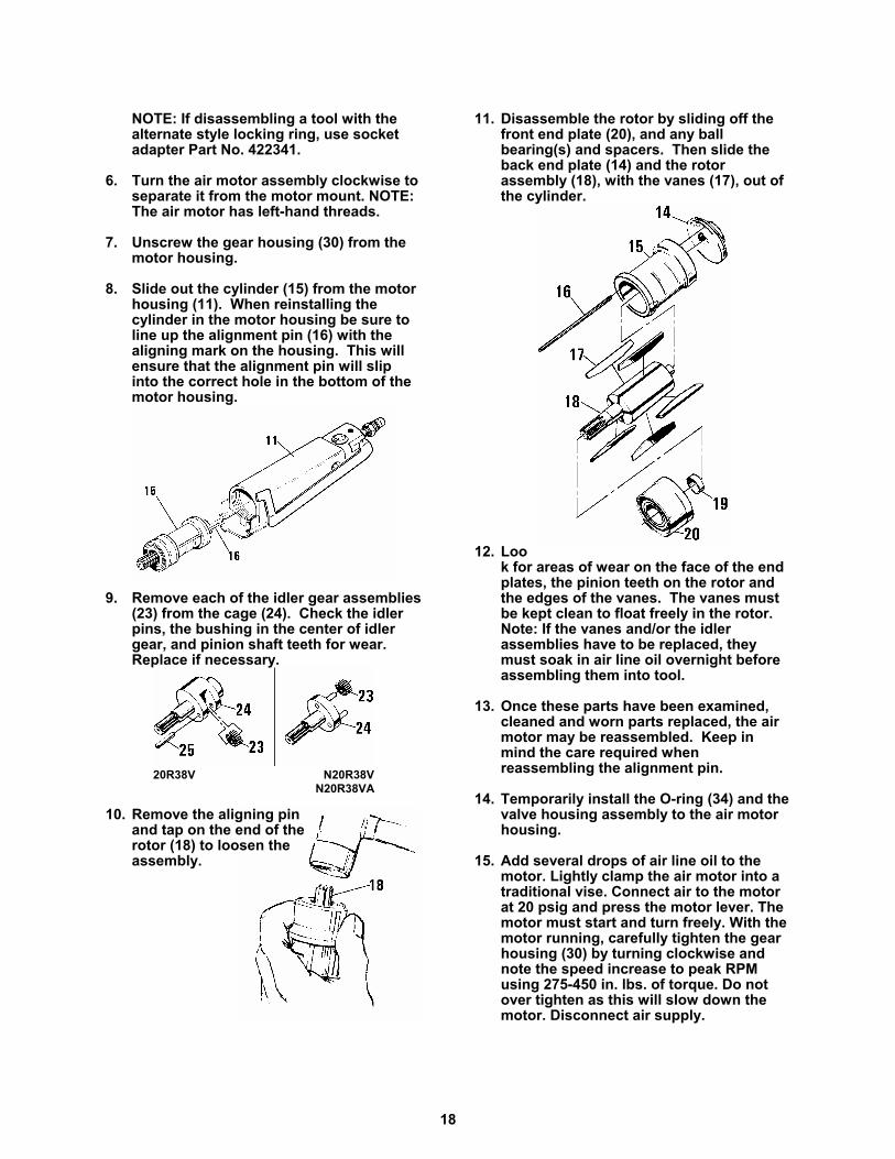
20R38V N20R38VN20R38VA
NOTE: If disassembling a tool with thealternate style locking ring, use socketadapter Part No. 422341.
6. Turn the air motor assembly clockwise toseparate it from the motor mount. NOTE:The air motor has left-hand threads.
7. Unscrew the gear housing (30) from themotor housing.
8. Slide out the cylinder (15) from the motorhousing (11). When reinstalling thecylinder in the motor housing be sure toline up the alignment pin (16) with thealigning mark on the housing. This willensure that the alignment pin will slipinto the correct hole in the bottom of themotor housing.
9. Remove each of the idler gear assemblies(23) from the cage (24). Check the idlerpins, the bushing in the center of idlergear, and pinion shaft teeth for wear.Replace if necessary.
10. Remove the aligning pinand tap on the end of therotor (18) to loosen theassembly.
11. Disassemble the rotor by sliding off thefront end plate (20), and any ballbearing(s) and spacers. Then slide theback end plate (14) and the rotorassembly (18), with the vanes (17), out ofthe cylinder.
12. Look for areas of wear on the face of the endplates, the pinion teeth on the rotor andthe edges of the vanes. The vanes mustbe kept clean to float freely in the rotor.Note: If the vanes and/or the idlerassemblies have to be replaced, theymust soak in air line oil overnight beforeassembling them into tool.
13. Once these parts have been examined,cleaned and worn parts replaced, the airmotor may be reassembled. Keep inmind the care required whenreassembling the alignment pin.
14. Temporarily install the O-ring (34) and thevalve housing assembly to the air motorhousing.
15. Add several drops of air line oil to the motor. Lightly clamp the air motor into atraditional vise. Connect air to the motorat 20 psig and press the motor lever. Themotor must start and turn freely. With themotor running, carefully tighten the gearhousing (30) by turning clockwise andnote the speed increase to peak RPMusing 275-450 in. lbs. of torque. Do notover tighten as this will slow down themotor. Disconnect air supply.
19
16. Remove the air motor from the vise.Clean the motor mounting threads withan appropriate solvent, also clean thethreads of the motor mount. Removethe valve housing assembly and O-ringfrom the air motor.
17. Place a few drops of Loctite #242sealant on both the external threads ofthe air motor and the internal threads ofthe mount. Screw the air motor into themotor mount until fully seated. Back outthe air motor only enough to align themotor to the mount when placed intothe assembly fixture.
18. Place the air motor and mount into theassembly fixture. Make sure the pinwhich extends out from the base of thefixture is properly aligned into thecavity found in the rear of the motormount. Securely clamp the motor inplace.
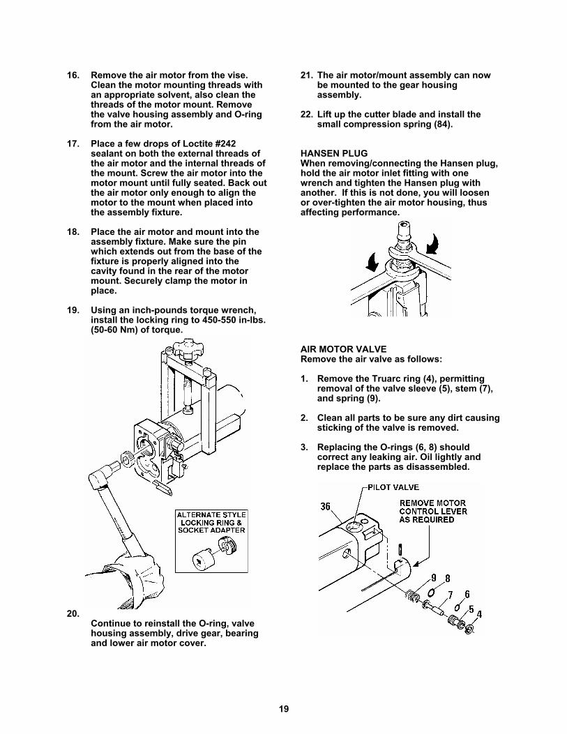
19. Using an inch-pounds torque wrench,install the locking ring to 450-550 in-lbs.(50-60 Nm) of torque.
20.Continue to reinstall the O-ring, valvehousing assembly, drive gear, bearingand lower air motor cover.
21. The air motor/mount assembly can nowbe mounted to the gear housingassembly.
22. Lift up the cutter blade and install thesmall compression spring (84).
HANSEN PLUGWhen removing/connecting the Hansen plug,hold the air motor inlet fitting with onewrench and tighten the Hansen plug withanother. If this is not done, you will loosenor over-tighten the air motor housing, thusaffecting performance.
AIR MOTOR VALVE Remove the air valve as follows:
1. Remove the Truarc ring (4), permittingremoval of the valve sleeve (5), stem (7),and spring (9).
2. Clean all parts to be sure any dirt causingsticking of the valve is removed.
3. Replacing the O-rings (6, 8) shouldcorrect any leaking air. Oil lightly andreplace the parts as disassembled.
20
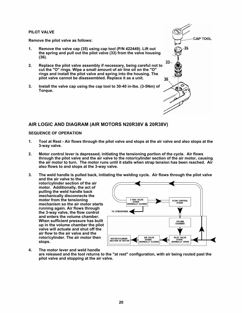
PILOT VALVE
Remove the pilot valve as follows:
1. Remove the valve cap (35) using cap tool (P/N 422449). Lift outthe spring and pull out the pilot valve (33) from the valve housing(36).
2. Replace the pilot valve assembly if necessary, being careful not tocut the "O" rings. Wipe a small amount of air line oil on the "O"rings and install the pilot valve and spring into the housing. Thepilot valve cannot be disassembled. Replace it as a unit.
3. Install the valve cap using the cap tool to 30-40 in-lbs. (3-5Nm) ofTorque.
AIR LOGIC AND DIAGRAM (AIR MOTORS N20R38V & 20R38V)
SEQUENCE OF OPERATION
1. Tool at Rest - Air flows through the pilot valve and stops at the air valve and also stops at the3-way valve.
2. Motor control lever is depressed, initiating the tensioning portion of the cycle. Air flowsthrough the pilot valve and the air valve to the rotor/cylinder section of the air motor, causingthe air motor to turn. The motor runs until it stalls when strap tension has been reached. Airalso flows to and stops at the 3-way valve.
3. The weld handle is pulled back, initiating the welding cycle. Air flows through the pilot valveand the air valve to therotor/cylinder section of the airmotor. Additionally, the act ofpulling the weld handle backmechanically disconnects themotor from the tensioningmechanism so the air motor startsrunning again. Air flows throughthe 3-way valve, the flow controland enters the volume chamber.When sufficient pressure has builtup in the volume chamber the pilotvalve will actuate and shut off theair flow to the air valve and therotor/cylinder. The air motor thenstops.
4. The motor lever and weld handleare released and the tool returns to the "at rest" configuration, with air being routed past thepilot valve and stopping at the air valve.
21
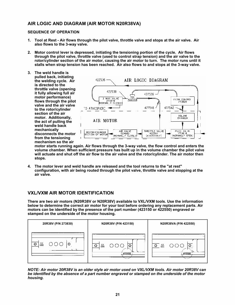
AIR LOGIC AND DIAGRAM (AIR MOTOR N20R38VA)
SEQUENCE OF OPERATION
1. Tool at Rest - Air flows through the pilot valve, throttle valve and stops at the air valve. Airalso flows to the 3-way valve.
2. Motor control lever is depressed, initiating the tensioning portion of the cycle. Air flowsthrough the pilot valve, throttle valve (used to control strap tension) and the air valve to therotor/cylinder section of the air motor, causing the air motor to turn. The motor runs until itstalls when strap tension has been reached. Air also flows to and stops at the 3-way valve.
3. The weld handle ispulled back, initiatingthe welding cycle. Airis directed to thethrottle valve (openingit fully allowing full airmotor performance)flows through the pilotvalve and the air valveto the rotor/cylindersection of the airmotor. Additionally,the act of pulling theweld handle backmechanicallydisconnects the motorfrom the tensioningmechanism so the airmotor starts running again. Air flows through the 3-way valve, the flow control and enters thevolume chamber. When sufficient pressure has built up in the volume chamber the pilot valvewill actuate and shut off the air flow to the air valve and the rotor/cylinder. The air motor thenstops.
4. The motor lever and weld handle are released and the tool returns to the "at rest"configuration, with air being routed through the pilot valve, throttle valve and stopping at theair valve.
VXL/VXM AIR MOTOR IDENTIFICATIONThere are two air motors (N20R38V or N20R38V) available to VXL/VXM tools. Use the informationbelow to determine the correct air motor for your tool before ordering any replacement parts. Airmotors can be identified by the presence of the part number (423150 or 422550) engraved orstamped on the underside of the motor housing.
20R38V (P/N 273830) N20R38V (P/N 423150) N20R38VA (P/N 422550)
NOTE: Air motor 20R38V is an older style air motor used on VXL/VXM tools. Air motor 20R38V canbe identified by the absence of a part number engraved or stamped on the underside of the motorhousing.
22
PARTS LIST, AIR MOTOR N20R38VA (422550)
KEY QTY PART# DESCRIPTION
1 1 020704 Quick disconnect plug2 1 024631 Filter assembly3 2 273822 Fitting4 1 024688 Truarc, #N5000-455 1 024686 Valve sleeve6 1 091624 O-ring7 1 024685 Valve stem8 1 020728 O-ring9 1 024683 Valve spring10 1 004658 Roll pin 1/8 x 13/1611 1 422592 Motor housing13 1 024633 Ball bearing14 1 024643 Back end plate15 1 024623 Cylinder16 1 024687 Align pin17 5 024612 Vane18 1 422874 Rotor19 1 024602 Spacer20 1 422819 Front end plate21 2 023481 Ball bearing22 1 423151 Washer23 3 422869 Idler assembly24 1 422947 Idler carrier assembly25 1 422822 Washer, plastic27 1 422870 Ring gear28 1 023551 Seal 29 1 023556 Pin30 1 024682 Gear housing31 1 422523 Cover32 3 015298 SHCS, 8-32 x 5/833 1 273818 Pilot Valve34 1 023446 O-ring35 1 276845 Valve cap36 1 422529 Valve housing assy37 2 274438 Screw38 1 422534 Motor control lever39 1 422536 Tubing (9" length)40 1 422537 Tubing (6" length)41 1 280522 Information tag42 1 422539 Tubing (1/2" length)43 1 422538 Tubing (5/8" length)44 1 422546 Tubing (8" length)45 1 422533 Tee46 1 422596 Spring47 1 422597 Throttle valve48 1 422598 Throttle valve cap49 1 422535 Adjustment screw50 3 094295 O-Ring51 1 435824 Information sign52 1 274442 Fitting61 1 274073 Return spring62 3 022789 O-Ring
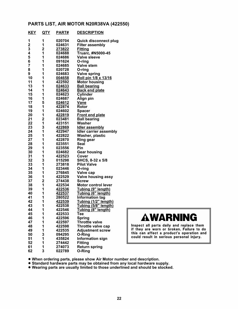
! When ordering parts, please show Air Motor number and description.! Standard hardware parts may be obtained from any local hardware supply. ! Wearing parts are usually limited to those underlined and should be stocked.

23
� The pilot valve (Key 33) must only be serviced by an authorized Signode Service Facility ora maintenance person trained by Signode.
� NEVER remove the pilot valve when air is connected to the tool. Removing a pilot valvewith air to the tool will cause the valve to violently release from the tool.
� Failure to follow the above could result in severe personal injury.

24
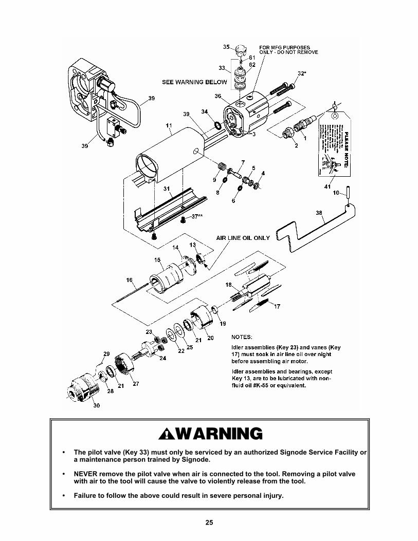
PARTS LIST, AIR MOTOR N20R38V(423150)
KEY QTY PART# DESCRIPTION
1 1 020704 Quick disconnect plug2 1 024631 Filter assembly3 2 273822 Fitting4 1 024688 Truarc, #N5000-455 1 024686 Valve sleeve6 1 091624 O-ring7 1 024685 Valve stem8 1 020728 O-ring9 1 024683 Valve spring10 1 004658 Roll pin 1/8 x 13/1611 1 273888 Motor housing13 1 024633 Ball bearing14 1 024643 Back end plate15 1 024623 Cylinder16 1 024687 Align pin17 5 024612 Vane18 1 422874 Rotor19 1 024602 Spacer20 1 422819 Front end plate21 2 023481 Ball bearing22 1 423151 Washer23 3 422869 Idler assembly24 1 422949 Idler carrier assembly25 1 422822 Washer, plastic27 1 422870 Ring gear28 1 023551 Seal 29 1 023556 Pin30 1 024682 Gear housing31 1 274435 Cover32 3 015298 SHCS, 8-32 x 5/833 1 273818 Pilot Valve34 1 023446 O-ring35 1 276845 Valve cap36 1 422529 Valve housing assy37 2 274438 Screw38 1 422312 Motor control lever39 2' 273821 Tubing41 1 280522 Information tag61 1 274073 Return spring62 3 022789 O-Ring
! When ordering parts, please show Air Motor number and description.! Standard hardware parts may be obtained from any local hardware supply. ! Wearing parts are usually limited to those underlined and should be stocked.
25
� The pilot valve (Key 33) must only be serviced by an authorized Signode Service Facility ora maintenance person trained by Signode.
� NEVER remove the pilot valve when air is connected to the tool. Removing a pilot valvewith air to the tool will cause the valve to violently release from the tool.
� Failure to follow the above could result in severe personal injury.

26
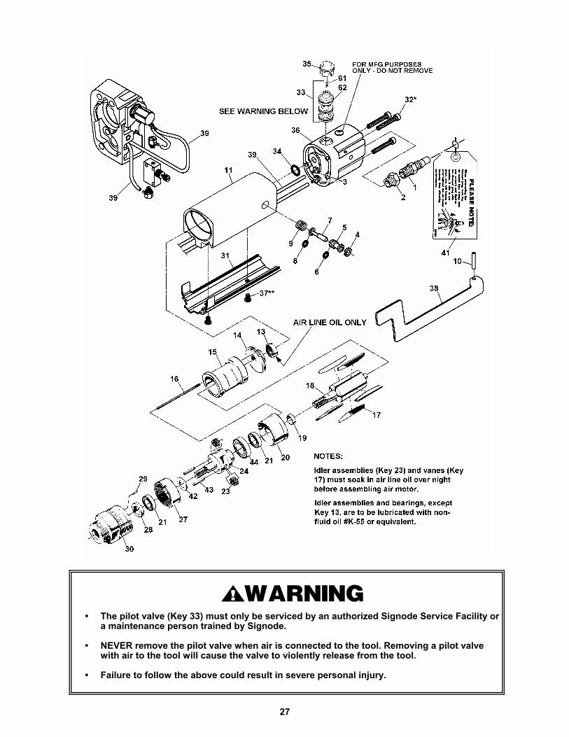
PARTS LIST, AIR MOTOR 20R38V(273830)
KEY QTY PART # DESCRIPTION
1 1 020704 Quick disconnect plug2 1 024631 Filter assembly3 2 273822 Fitting4 1 024688 Truarc, #N5000-455 1 024686 Valve sleeve6 1 091624 O-ring7 1 024685 Valve stem8 1 020728 O-ring9 1 024683 Valve spring10 1 004658 Roll pin 1/8 x 13/1611 1 273888 Motor housing13 1 024633 Ball bearing14 1 024643 Back end plate15 1 024623 Cylinder16 1 024687 Align pin17 5 024612 Vane18 1 024625 Rotor19 1 024602 Spacer20 1 024622 Front end plate21 2 023481 Ball bearing23 2 024607 Idler assembly24 1 024621 Cage27 1 024608 Ring gear28 1 023551 Seal 29 1 023556 Pin30 1 024682 Gear housing31 1 274435 Cover32 3 015298 SHCS, 8-32 x 5/833 1 273818 Pilot Valve34 1 023446 O-ring35 1 273845 Valve cap36 1 422529 Valve housing assy37 2 274438 Screw38 1 422312 Motor control lever39 2' 273821 Tubing41 1 280522 Information tag42 1 024601 Retainer43 2 023555 Pin44 1 023552 Ball bearing61 1 274073 Return spring62 3 022789 O-Ring
! When ordering parts, please show Air Motor number and description.! Standard hardware parts may be obtained from any local hardware supply. ! Wearing parts are usually limited to those underlined and should be stocked.
27
� The pilot valve (Key 33) must only be serviced by an authorized Signode Service Facility ora maintenance person trained by Signode.
� NEVER remove the pilot valve when air is connected to the tool. Removing a pilot valvewith air to the tool will cause the valve to violently release from the tool.
� Failure to follow the above could result in severe personal injury.

28
PARTS LIST, TOOLKEY QTY PART # DESCRIPTION
4 3 423370 Set screw5 1 273881 End cap 6 1 023096 O-ring7 1 023097 Bearing, Faf. #9101K8 1 023082 O-ring9 1 023014 Spacer10 1 014567 Gear, VXL
1 023002 Gear, VXM11 1 008734 Bearing, Faf. #B-54212 1 008552 Oil seal14 1 306842 Handle15 2 023093 Key, Woodruff 213
alloy steel16 1 306863 Tensioner foot17 1 274104 Gripper plug18 1 274105 Strap guide, (1/2")
1 014565 Strap guide, (7/16")19 1 004860 FHSCS, 10-32 x 3/820 1 008624 Roll pin, 1/8 x 1/421 1 014515 Feedwheel shaft22 1 014518 Feedwheel23 1 423460 Spring torsion24 1 273847 Weld housing25 1 274068 Support pin26 1 273861 Eccentric shaft27 1 273859 Idler Gear27A 1 422913 Gear/Bearing assy28 1 014566 Spiroid worm, VXL
1 014517 Spiroid worm, VXM29 1 014530 Needle bearing,
Torrington #B-4730 1 014522 Pin31 1 014527 Bearing,
Fafnir #7202W32 1 014556 Washer33 2 014549 Brake spring34 1 306839 Brake35 1 273886 Spacer sleeve36 1 014542 Clutch spring37 1 306865 Clutch38 1 014529 Bearing needle,
Torrington #B-6839 1 161156 Drive gear 39A 1 161157 Gear/Bearing assy40 1 014528 Bearing41 1 273852 Motor mount42 1 422301 Locking ring43 1 273883 Compression plate44 1 273858 Contact stem45 1 273812 Die spring46 1 422111 Cutter blade47 1 306869 Pin48 1 422122 Slider link49 1 273850 Lift tab50 1 273842 Pin
KEY QTY PART # DESCRIPTION
51 1 422110 Pin, pivot52 1 422121 Upper gripper "Z"53 1 273820 Flow control54 2 274442 Fitting56 1 273819 3-way valve58 1 273827 Oil seal60 1 422549 Weld handle61 1 422575 Knob64 1 273815 Bushing65 1 273816 Bushing66 1 273823 Pressure Eccentric68 1 007631 Roll pin, 1/8 X 5/869 1 023446 O-ring70 1 286392 Warning sign71 1 286349 Nameplate, VXL-Z
1 286350 Nameplate, VXM-Z72 1 273854 Gear housing73 1 023963 Brush, not shown74 1 273814 Pivot pin, cutter75 2 016342 SHCS,¼-20 x 1½76 4 009041 SHCS,¼-20 x ¾78 1 273808 Lower gripper "Z"79 1 273824 Needle bearing80 2 273825 Needle bearing81 1 273828 Shim82 1 422571 Disk83 1 261385 Wear pin84 1 045203 Compression spring,
LEE #LC-020 A-585 1 273838 Stripper pin86 1 273834 Spacer, ¼-2087 1 306545 Slotted screw,
4-40 x 3/1688 2 306847 Adjustment screw92 1 008746 SHCS, ¼-20 x 3/894 1 286373 3-Icon info. sign95 1 433392 Information tag
NOTES:
! Keys 27 and 80 comprise assembly 27A.
! Keys 38 and 39 comprise assembly 39A.
! When ordering parts, please show tool model, part number and description.
! Standard hardware parts may be obtained from any local hardware supply.
! Wearing parts are usually limited to those underlined and should be stocked.

29
30
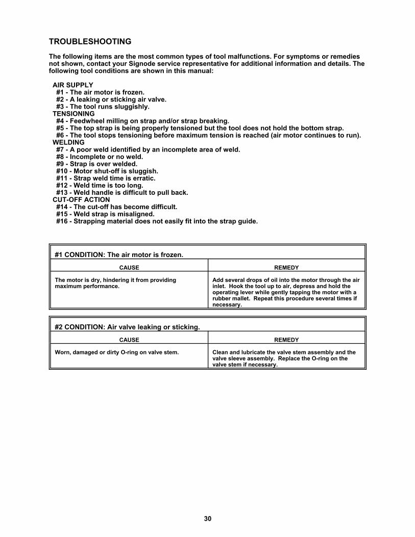
TROUBLESHOOTING
The following items are the most common types of tool malfunctions. For symptoms or remediesnot shown, contact your Signode service representative for additional information and details. Thefollowing tool conditions are shown in this manual:
AIR SUPPLY #1 - The air motor is frozen. #2 - A leaking or sticking air valve. #3 - The tool runs sluggishly. TENSIONING #4 - Feedwheel milling on strap and/or strap breaking. #5 - The top strap is being properly tensioned but the tool does not hold the bottom strap. #6 - The tool stops tensioning before maximum tension is reached (air motor continues to run). WELDING #7 - A poor weld identified by an incomplete area of weld. #8 - Incomplete or no weld. #9 - Strap is over welded. #10 - Motor shut-off is sluggish. #11 - Strap weld time is erratic. #12 - Weld time is too long. #13 - Weld handle is difficult to pull back. CUT-OFF ACTION #14 - The cut-off has become difficult. #15 - Weld strap is misaligned. #16 - Strapping material does not easily fit into the strap guide.
#1 CONDITION: The air motor is frozen.
CAUSE REMEDY
The motor is dry, hindering it from providingmaximum performance.
Add several drops of oil into the motor through the airinlet. Hook the tool up to air, depress and hold theoperating lever while gently tapping the motor with arubber mallet. Repeat this procedure several times ifnecessary.
#2 CONDITION: Air valve leaking or sticking.
CAUSE REMEDY
Worn, damaged or dirty O-ring on valve stem. Clean and lubricate the valve stem assembly and thevalve sleeve assembly. Replace the O-ring on thevalve stem if necessary.
31
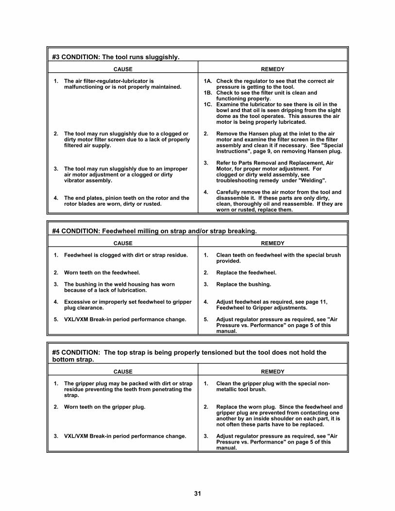
#3 CONDITION: The tool runs sluggishly.
CAUSE REMEDY
1. The air filter-regulator-lubricator ismalfunctioning or is not properly maintained.
2. The tool may run sluggishly due to a clogged ordirty motor filter screen due to a lack of properlyfiltered air supply.
3. The tool may run sluggishly due to an improperair motor adjustment or a clogged or dirtyvibrator assembly.
4. The end plates, pinion teeth on the rotor and therotor blades are worn, dirty or rusted.
1A. Check the regulator to see that the correct airpressure is getting to the tool.
1B. Check to see the filter unit is clean andfunctioning properly.
1C. Examine the lubricator to see there is oil in thebowl and that oil is seen dripping from the sightdome as the tool operates. This assures the airmotor is being properly lubricated.
2. Remove the Hansen plug at the inlet to the airmotor and examine the filter screen in the filterassembly and clean it if necessary. See "SpecialInstructions", page 9, on removing Hansen plug.
3. Refer to Parts Removal and Replacement, AirMotor, for proper motor adjustment. Forclogged or dirty weld assembly, seetroubleshooting remedy under "Welding".
4. Carefully remove the air motor from the tool anddisassemble it. If these parts are only dirty,clean, thoroughly oil and reassemble. If they areworn or rusted, replace them.
#4 CONDITION: Feedwheel milling on strap and/or strap breaking.
CAUSE REMEDY
1. Feedwheel is clogged with dirt or strap residue.
2. Worn teeth on the feedwheel.
3. The bushing in the weld housing has wornbecause of a lack of lubrication.
4. Excessive or improperly set feedwheel to gripperplug clearance.
5. VXL/VXM Break-in period performance change.
1. Clean teeth on feedwheel with the special brushprovided.
2. Replace the feedwheel.
3. Replace the bushing.
4. Adjust feedwheel as required, see page 11,Feedwheel to Gripper adjustments.
5. Adjust regulator pressure as required, see "AirPressure vs. Performance" on page 5 of thismanual.
#5 CONDITION: The top strap is being properly tensioned but the tool does not hold thebottom strap.
CAUSE REMEDY
1. The gripper plug may be packed with dirt or strapresidue preventing the teeth from penetrating thestrap.
2. Worn teeth on the gripper plug.
3. VXL/VXM Break-in period performance change.
1. Clean the gripper plug with the special non-metallic tool brush.
2. Replace the worn plug. Since the feedwheel andgripper plug are prevented from contacting oneanother by an inside shoulder on each part, it isnot often these parts have to be replaced.
3. Adjust regulator pressure as required, see "AirPressure vs. Performance" on page 5 of thismanual.
32
TROUBLESHOOTING, Continued
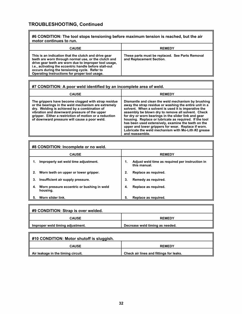
#6 CONDITION: The tool stops tensioning before maximum tension is reached, but the airmotor continues to run.
CAUSE REMEDY
This is an indication that the clutch and drive gearteeth are worn through normal use, or the clutch anddrive gear teeth are worn due to improper tool usage,i.e., activating the eccentric handle before stall-outoccurs during the tensioning cycle. Refer toOperating Instructions for proper tool usage.
These parts must be replaced. See Parts Removaland Replacement Section.
#7 CONDITION: A poor weld identified by an incomplete area of weld.
CAUSE REMEDY
The grippers have become clogged with strap residueor the bearings in the weld mechanism are extremelydry. Welding is achieved by a combination ofvibration and downward pressure of the uppergripper. Either a restriction of motion or a reductionof downward pressure will cause a poor weld.
Dismantle and clean the weld mechanism by brushingaway the strap residue or washing the entire unit in asolvent. When a solvent is used it is imperative theassembly be blown dry to remove all solvent. Checkfor dry or worn bearings in the slider link and gearhousing. Replace or lubricate as required. If the toolhas been used extensively, examine the teeth on theupper and lower grippers for wear. Replace if worn. Lubricate the weld mechanism with Mo-Lith #2 greaseand reassemble.
#8 CONDITION: Incomplete or no weld.
CAUSE REMEDY
1. Improperly set weld time adjustment.
2. Worn teeth on upper or lower gripper.
3. Insufficient air supply pressure.
4. Worn pressure eccentric or bushing in weldhousing.
5. Worn slider link.
1. Adjust weld time as required per instruction inthis manual.
2. Replace as required.
3. Remedy as required.
4. Replace as required.
5. Replace as required.
#9 CONDITION: Strap is over welded.
CAUSE REMEDY
Improper weld timing adjustment. Decrease weld timing as needed.
#10 CONDITION: Motor shutoff is sluggish.
CAUSE REMEDY
Air leakage in the timing circuit. Check air lines and fittings for leaks.
33
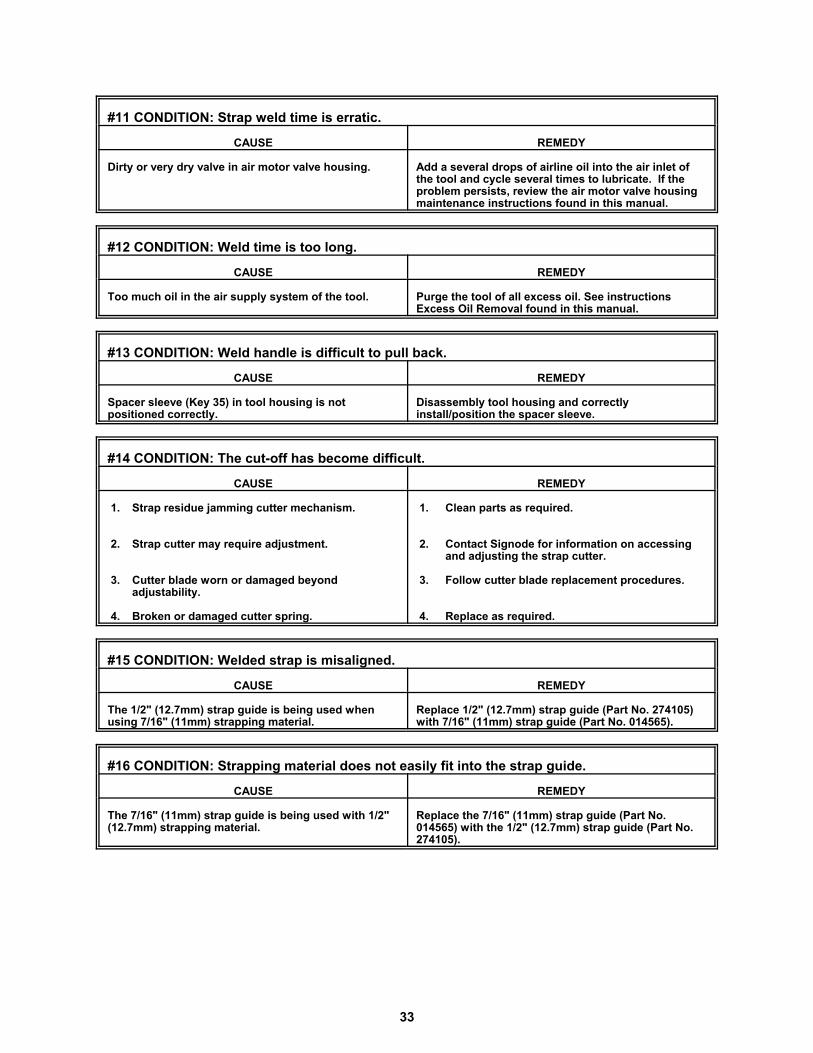
#11 CONDITION: Strap weld time is erratic.
CAUSE REMEDY
Dirty or very dry valve in air motor valve housing. Add a several drops of airline oil into the air inlet ofthe tool and cycle several times to lubricate. If theproblem persists, review the air motor valve housingmaintenance instructions found in this manual.
#12 CONDITION: Weld time is too long.
CAUSE REMEDY
Too much oil in the air supply system of the tool. Purge the tool of all excess oil. See instructionsExcess Oil Removal found in this manual.
#13 CONDITION: Weld handle is difficult to pull back.
CAUSE REMEDY
Spacer sleeve (Key 35) in tool housing is notpositioned correctly.
Disassembly tool housing and correctlyinstall/position the spacer sleeve.
#14 CONDITION: The cut-off has become difficult.
CAUSE REMEDY
1. Strap residue jamming cutter mechanism.
2. Strap cutter may require adjustment.
3. Cutter blade worn or damaged beyondadjustability.
4. Broken or damaged cutter spring.
1. Clean parts as required.
2. Contact Signode for information on accessingand adjusting the strap cutter.
3. Follow cutter blade replacement procedures.
4. Replace as required.
#15 CONDITION: Welded strap is misaligned.
CAUSE REMEDY
The 1/2" (12.7mm) strap guide is being used whenusing 7/16" (11mm) strapping material.
Replace 1/2" (12.7mm) strap guide (Part No. 274105)with 7/16" (11mm) strap guide (Part No. 014565).
#16 CONDITION: Strapping material does not easily fit into the strap guide.
CAUSE REMEDY
The 7/16" (11mm) strap guide is being used with 1/2"(12.7mm) strapping material.
Replace the 7/16" (11mm) strap guide (Part No.014565) with the 1/2" (12.7mm) strap guide (Part No.274105).
34
MAINTENANCE
TOOL
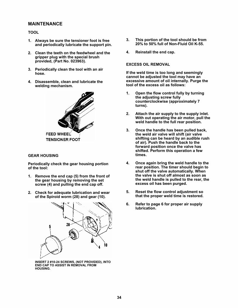
1. Always be sure the tensioner foot is freeand periodically lubricate the support pin.
2. Clean the teeth on the feedwheel and the gripper plug with the special brushprovided, (Part No. 023963).
3. Periodically clean the tool with an airhose.
4. Disassemble, clean and lubricate thewelding mechanism.
GEAR HOUSING
Periodically check the gear housing portionof the tool:
1. Remove the end cap (5) from the front ofthe gear housing by removing the setscrew (4) and pulling the end cap off.
2. Check for adequate lubrication and wearof the Spiroid worm (28) and gear (10).
INSERT 2 #10-24 SCREWS, (NOT PROVIDED), INTOEND CAP TO ASSIST IN REMOVAL FROMHOUSING.
3. This portion of the tool should be from20% to 50% full of Non-Fluid Oil K-55.
4. Reinstall the end cap.
EXCESS OIL REMOVAL
If the weld time is too long and seeminglycannot be adjusted the tool may have anexcessive amount of oil internally. Purge thetool of the excess oil as follows:
1. Open the flow control fully by turningthe adjusting screw fullycounterclockwise (approximately 7turns).
2. Attach the air supply to the supply inlet.With out operating the air motor, pull theweld handle to the full rear position.
3. Once the handle has been pulled back,the weld air valve will shift (air valveshifting can be heard by an audible rushof air). Push the handle back to theforward position once the valve hasshifted. Perform this operation a fewtimes.
4. Once again bring the weld handle to therear position. The timer should begin toshut off the valve automatically. Whenthe valve is shut off almost as soon asthe weld handle is pulled to the rear, theexcess oil has been purged.
5. Reset the flow control adjustment sothat the proper weld time is restored.
6. Refer to page 6 for proper air supplylubrication.
35
TOOL OPTIONS
OVERHEAD SUSPENSION
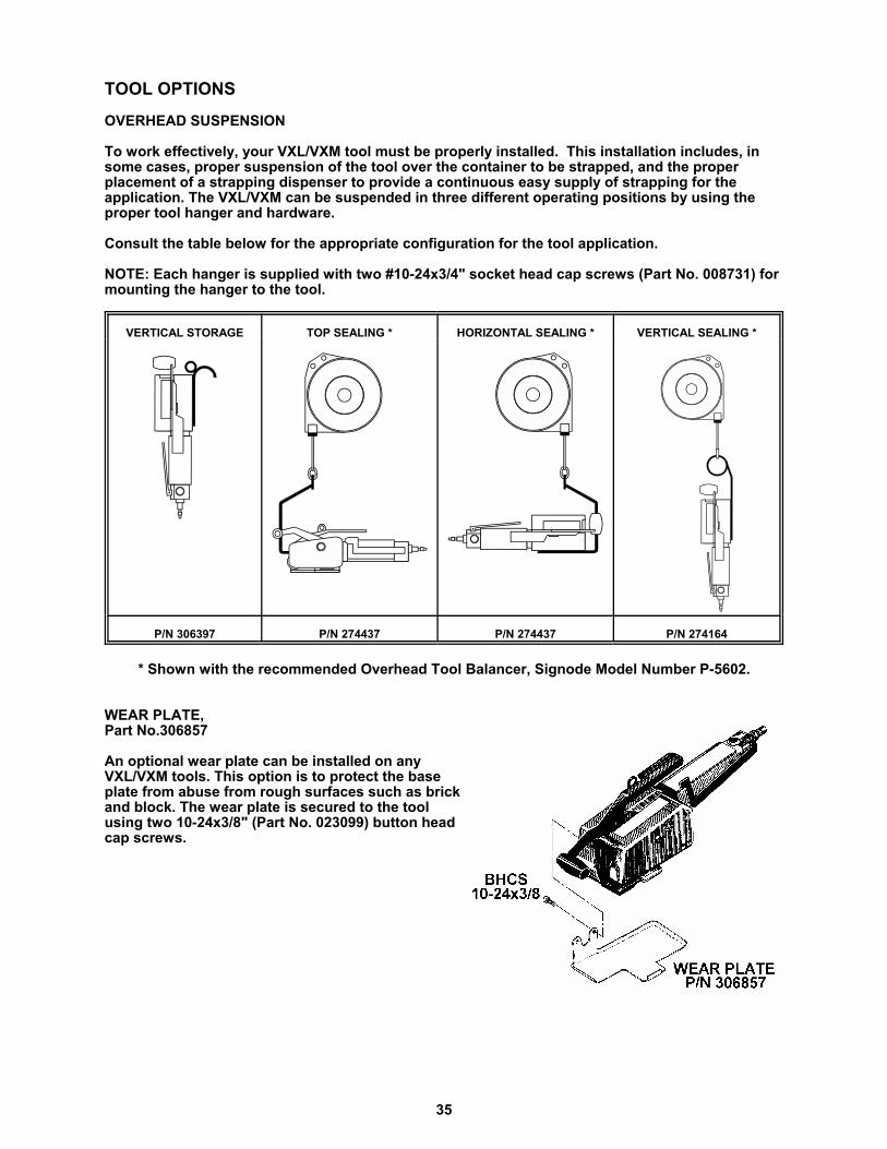
To work effectively, your VXL/VXM tool must be properly installed. This installation includes, insome cases, proper suspension of the tool over the container to be strapped, and the properplacement of a strapping dispenser to provide a continuous easy supply of strapping for theapplication. The VXL/VXM can be suspended in three different operating positions by using theproper tool hanger and hardware.
Consult the table below for the appropriate configuration for the tool application.
NOTE: Each hanger is supplied with two #10-24x3/4" socket head cap screws (Part No. 008731) formounting the hanger to the tool.
VERTICAL STORAGE TOP SEALING * HORIZONTAL SEALING * VERTICAL SEALING *
P/N 306397 P/N 274437 P/N 274437 P/N 274164
* Shown with the recommended Overhead Tool Balancer, Signode Model Number P-5602.
WEAR PLATE,Part No.306857
An optional wear plate can be installed on anyVXL/VXM tools. This option is to protect the baseplate from abuse from rough surfaces such as brickand block. The wear plate is secured to the toolusing two 10-24x3/8" (Part No. 023099) button headcap screws.
36
TOOL OPTIONS, Continued
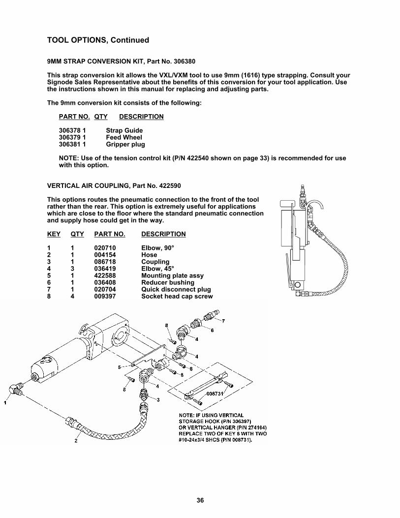
9MM STRAP CONVERSION KIT, Part No. 306380
This strap conversion kit allows the VXL/VXM tool to use 9mm (1616) type strapping. Consult yourSignode Sales Representative about the benefits of this conversion for your tool application. Usethe instructions shown in this manual for replacing and adjusting parts.
The 9mm conversion kit consists of the following:
PART NO. QTY DESCRIPTION
306378 1 Strap Guide306379 1 Feed Wheel306381 1 Gripper plug
NOTE: Use of the tension control kit (P/N 422540 shown on page 33) is recommended for usewith this option.
VERTICAL AIR COUPLING, Part No. 422590
This options routes the pneumatic connection to the front of the toolrather than the rear. This option is extremely useful for applicationswhich are close to the floor where the standard pneumatic connectionand supply hose could get in the way.
KEY QTY PART NO. DESCRIPTION
1 1 020710 Elbow, 90°2 1 004154 Hose3 1 086718 Coupling4 3 036419 Elbow, 45°5 1 422588 Mounting plate assy6 1 036408 Reducer bushing7 1 020704 Quick disconnect plug8 4 009397 Socket head cap screw
37
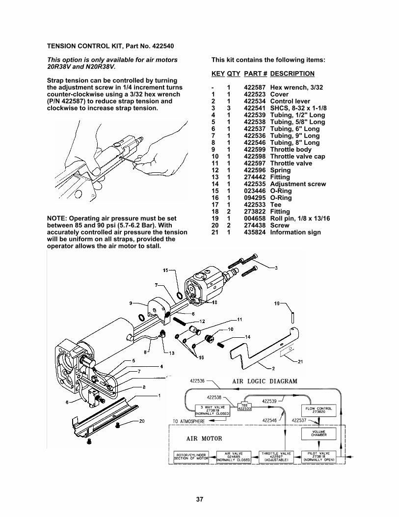
TENSION CONTROL KIT, Part No. 422540
This option is only available for air motors20R38V and N20R38V.
Strap tension can be controlled by turningthe adjustment screw in 1/4 increment turnscounter-clockwise using a 3/32 hex wrench(P/N 422587) to reduce strap tension andclockwise to increase strap tension.
NOTE: Operating air pressure must be setbetween 85 and 90 psi (5.7-6.2 Bar). Withaccurately controlled air pressure the tensionwill be uniform on all straps, provided theoperator allows the air motor to stall.
This kit contains the following items:
KEY QTY PART # DESCRIPTION
- 1 422587 Hex wrench, 3/321 1 422523 Cover2 1 422534 Control lever3 3 422541 SHCS, 8-32 x 1-1/84 1 422539 Tubing, 1/2" Long5 1 422538 Tubing, 5/8" Long6 1 422537 Tubing, 6" Long7 1 422536 Tubing, 9" Long8 1 422546 Tubing, 8" Long9 1 422599 Throttle body10 1 422598 Throttle valve cap11 1 422597 Throttle valve12 1 422596 Spring13 1 274442 Fitting14 1 422535 Adjustment screw15 1 023446 O-Ring16 1 094295 O-Ring17 1 422533 Tee18 2 273822 Fitting19 1 004658 Roll pin, 1/8 x 13/1620 2 274438 Screw21 1 435824 Information sign

38

39
EU Declaration of ConformityThe Supply of Machinery (safety) Regulations
1992 (S.I. 1992/3073)
It is hereby declared that the undermentioned machinery has been designed andconstructed to comply with the health and safety requirements defined in ECDirective 89/392/EEC
Machine Supplier: Signode, Division of ITW Ltd.Queensway, FforestfachSwansea SA5 4ED
Machine Description: VXL/VXM-2000Z
Machine Type: Pneumatic Combination Hand Strapping tool.
Provisions with which machine complies:
89/392/EEC, 91/368/EEC
Harmonized EuroNorms with which machine complies:
EN 292:1, EN 292:2, EN 294, EN 349
Technical Standards with which machine complies:
NA
Signature: Date: 1 Sept 2000
(Peter Oseland)

© Copyright 2001, Signode 286139 Rev. 9/2001
SIGNODENEW TOOL WARRANTY
Signode Engineered Products Warrants that a new Signode strapping tool will operate per functionalspecifications for a period of sixty (60) days after the date of shipment to the owner's place of business.Normal wearing parts, as outlined in the Operation, Parts & Safety manual, are covered by a thirty (30) daywarranty unless, in Signode's judgement, these parts have been subjected to abnormal or extreme usage.Signode's sole liability hereunder will be to repair or replace, without charge, F.O.B. Signode's Glenview,Illinois plant, any tool which proves to not operate per functional specifications within the stated period.Signode reserves the right to replace any tool which proves not to operate per functional specificationswith a new or like-new tool of the same model if in Signode's judgement such replacement is appropriate.Any new replacement tool provided to an owner will carry a full sixty (60) day warranty. Any warrantyrepaired tool or like-new replacement tool will carry a warranty for the balance of the time remaining on theinitial sixty (60) day warranty. This warranty will be extended to compensate for the time the tool is inSignode's possession for warranty repairs.
This warranty is void as to any tool which has been: (I) subjected to mis-use, misapplication, accident,damage, or repaired with other than genuine Signode replacement parts, (II) improperly maintained, oradjusted, or damaged in transit or handling; (III) used with improperly filtered, unlubricated air or improperstrapping material, (IV) in Signode's opinion, altered or repaired in a way that affects or detracts from theperformance of the tool.
SIGNODE MAKES NO WARRANTY, EXPRESSED OR IMPLIED, RELATING TO MERCHANTABILITY,FITNESS OR OTHERWISE EXCEPT AS STATED ABOVE AND SIGNODE'S LIABILITY AS ASSUMED ABOVEIS IN LIEU OF ALL OTHERS ARISING OUT OF OR IN CONNECTION WITH THE USE AND PERFORMANCEOF THE TOOL. IT IS EXPRESSLY UNDERSTOOD THAT SIGNODE SHALL IN NO EVENT BE LIABLE FORANY INDIRECT OR CONSEQUENTIAL DAMAGES INCLUDING, BUT NOT LIMITED TO, DAMAGES WHICHMAY ARISE FROM LOSS OF ANTICIPATED PROFITS OR PRODUCTION, SPOILAGE OF MATERIALS,INCREASED COSTS OF OPERATION OR OTHERWISE.
Considerable effort has be made to ensure that this product conforms to our high quality standards.However, should you experience any difficulties, please contact your Sales Representative providingsamples and the manufacturing code specified on the tool.
Thank you for your help.
SIGNODE ENGINEERED PRODUCTSHand Tool Division
3620 W. Lake Avenue, Glenview, Illinois 60025