terminal stations design for submarine hvac links · terminal stations design for submarine hvac...
TRANSCRIPT

Terminal stations design for submarine HVAC links Capri-Italy and Malta-Sicily interconnections
E. Di Bartolomeo, A. Di Giulio, F. Palone, M. Rebolini, V. Iuliani, Engineering dept. Terna Rete Italia
Rome, Italy [email protected]
Abstract—Submarine interconnections allow for the connection of large islands to the onshore transmission grid and for the decommissioning of local power plants, which are often old, inefficient and polluting. High voltage alternating current (HVAC) cables are an interesting solution for smaller power ratings and distances up to 120 km, due to lower capital costs and absence of converting stations, if compared to HVDC links.
However the design of terminal stations of HVAC interconnections must account for some specific issues, such as switching equipment performance limits, reactive power compensation and insulation coordination.
The paper deals with two recent examples of HVAC submarine link, i.e. the Malta-Sicily and Capri-Italy interconnectors, focusing on terminal substation design and testing.
Keywords—HVAC; submarine cable; substation design; insulation coordination.
I. INTRODUCTION
Most of the main islands in the Mediterranean sea are already interconnected with the nearest shore by means of ac or dc submarine cables. As regards Italy, the two largest islands of Sicily and Sardinia have been connected respectively in 1956 (with a 150 kV ac, 3650 m long single span overhead line) and 1964 (with a mixed overhead/submarine HVDC interconnection).
Several projects are currently in progress, or have recently been completed, for interconnecting some of the remaining islands, such as the Malta-Sicily and the Capri-Italy interconnectors. In both cases the main purpose of the links is to replace the local, fuel-oil based, generation, thus reducing operating cost and pollution and enhancing system reliability.
Both these projects entail the connection of a large island to the Italian National Transmission Network (RTN); although the Malta-Sicily cable will be owned and operated by ENEMALTA, TERNA has been deeply involved in the design, commissioning and testing phase, both as the Italian TSO and as ENEMALTA’s consultant.
Several challenges have been faced, both due to technical and environmental constraints; innovative solutions have thus been identified in order to overcome these issues without reducing the overall link reliability, using innovative schemes
and components. Detailed electrical, reliability and environmental studies have been carried out by TERNA; results have been validated by field tests during the commissioning phase.
The paper deals with the specific issues of these two links and with the design, commissioning and testing of their terminal stations.
II. PROJECTS DESCRIPTION
A. Capri-Italy link
Capri island, located at only few km from the Italian coast, is not still connected with the national transmission grid.
At present time the load (about 20 MW during the summer) is fed by a local power plant, owned by a private company, which relies on expensive and polluting fuel oil diesel generators.
In the last years [1] [2], several island-wide blackouts were caused by generator faults, particularly during the summer peak load, causing significant economic damages. In the same period air and pollution concerns have been raised, leading to investigation about the power plant [3].
In order to minimize outage risk, to avoid air and water pollution due to local generation and to reduce energy cost, Terna is currently commissioning a submarine cable link, for connecting Capri to the Italian mainland.
As a first stage a 30 km long, a 150 kV 3-core submarine cable has been laid between Capri harbor and Torre Annunziata; finally, a second submarine cable stretch (20 km long) will connect Capri with Sorrento peninsula, creating a ring and substantially increasing network reliability (see fig 1 below). Submarine cable characteristics are reported in table I.
The Capri terminal station, currently under construction, will include a new 150 kV /6 kV distribution centre which will feed the local distribution network.
TABLE I. CAPRI-ITALY CABLE CHARACTERISTICS
Power rating 160 MVA
Length 30 km
Capacitance 0.18µF/km

Fig. 1. Outline of the Capri-Italy 150 kVsubmarine cable ring project
B. Malta-Sicily link
Until 2015, Malta Island was one of the two EU states still not connected to the ENTSO-E network. The local load ( about 2.3 TWh/year , with a 425 MW peak load) has been fed by thermoelectric power plants, fueled with gasoil or fuel-oil.
In the last years fault events on aging power plants caused nation-wide outages [4]; high energy cost, and low reliability prompted the need for a safe interconnection with the European network.
Preliminary studies for the Malta-Sicily interconnector have been completed in 2010 by a joint Terna / Enemalta team [5]. The project has been completed in 2014 and commissioned in march 2015.
The Malta-Sicily interconnector is at present time the longest (120 km) HVAC cable in the world, connecting Terna’s Ragusa substation with Enemalta’s Maghtab distribution centre [6]. At present time the link is made by a single (20 km long) circuit underground cable line from Ragusa to the Sicilian shore and by a 3-core submarine cable (100 km long) from Marina di Ragusa to Maghtab, as represented in Fig.2.
With a 200 MW power rating, the link allows Enemalta access to the Italian network and energy market, substantially reducing the energy price and increasing security of supply. In a second phase another cable circuit will be laid, doubling the transfer capacity of the link.
III. TERNMINAL STATIONS DESIGN CHALLENGES
A. Technical challenges
1) Reactive power compensation Reactive power compensation is the main issue when
dealing with long HV cables. Shunt reactors have to be
installed at one or both ends of the link in order to cope with the reactive power surplus of the submarine cable line, increasing the power factory at the receiving ends and fulfilling the rated capacitive switching current constraint of circuit breakers.
.
Fig. 2. Malta Sicily submarine cable route [IEEE PD]
For shorter lines, such as the Capri-Italy link, the most significant constraint is the cable line charging current, which could exceed the rated capacitive switching current of circuit breakers. To deal with this issue it is sufficient to install a single shunt reactor at one end of the link, connected between the circuit breaker and the cable line itself.
For longer cables, such as the Malta-Sicily interconnector, an optimal reactive power profile is necessary in order to fully exploit cable active power transfer capability and shunt reactors must be installed at both ends of the link: being the line inhomogeneous, an asymmetrical shunt reactor compensating scheme has been implemented [6].
Furthermore, shunt reactors at receiving (Maltese) end of the link have been equipped with On-Load Tap Changer (OLTC) in order to control the power factor an perform voltage regulation on the Maltese grid.
2) Insulation coordination Cable networks exhibit little if any risks as regards
lightening overvoltages. By contrast switching overvoltages and harmonic resonances are a potentially troublesome issue.
The large cable capacitance reduces the first resonant network frequency fr, which can be estimated as:
(1)
Where Ssc is the short circuit power at the sending end and Qc the reactive power generated by the cable line.
Point On Wave (POW) switching devices have been installed in both projects in order to minimize shunt reactor
ERCOLANO
TORRE C.LE
CASTELLAMMARE
GRAGNANO
LETTERE
FINCANTIERI
NEW STATION CAPRI
TORRE NORD
S. GIUSEPPE
AGEROLAVICO EQ.
NEW STATIONSORRENTO
SCAFATI
TORRE SUD
NUOVA
SE 220/150 KV
SCAFATI
1° phase
2° phase
RAGUSA
Marina di Ragusa
Maghtab

inrush during cable energization, thus reducing the risk of triggering harmonic overvoltages.
B. Envirnmental costraints
Severe environmental constraints have been encountered during the design, authorization and construction phase of both the Malta-Sicily and Capri-Italy terminal stations.
Limited available space, proximity to the sea and presence of urbanized / touristic environment prompted the need for innovative substation schemes, which allow for a compact and environmental-friendly installation.
Indoor Gas Insulated Switchgears (GIS) have been foreseen at the receiving ends, reducing substation footprint while minimizing its visual impact.
C. Reliability
Due to the limited available local generation, even a temporary fault on one of the link terminal stations is likely to cause a severe outage on the receiving network. As a consequence reliability has been one of the key factors for the substation design.
The fault rates of Table II, based on Terna’s experience, have been considered.
TABLE II. EQUIPMENT FAULT RATES FOR RELIABILITY STUDY
GIS Bay 3.8% Shunt reactor
0.7%
AIS CB 2.7% AIS disc. 0.3%
AIS VT 0,1% AIS CT 0,3%
Severe tests have been carried out in order to assess equipment robustness. Most significantly short circuit withstand tests have been carried out on HV/MV transformers, which are the most critical components.
IV. CAPRI AND TORRE ANNUNZIATA TERMINAL STATIONS
A. Torre Annunziata
Terna’s Torre Annunziata station will be connected to an existing GIS distribution centre owned by the Italian DSO ENEL Distribuzione, located about 1 km away from the shore.
Due to limited space an Hybrid Air/Gas solution will be used; more in detail ABB’s 245 kV Plug and Switch System (PASS) will be used. The single line diagram is shown in Fig.3 below.
Fig. 3. Single line diagram of Torre Annunziata terminal station
During normal operation, the bypass disconnector C is open. In case of shunt reactor fault, the CB “B” will trip, allowing to continue safe operation of the link.
Line switching without the shunt reactor is still possible, as 245 kV-class circuit breakers have a sufficient capacitive rated switching current. In case of maintenance or failures on line circuit breaker “A”, the bypass switch will be closed, allowing for N-1 security. The expected failure rate is then dictated by the existing circuit breaker of the existing ENEL distribution centre and by the input bay on the new PASS, leading to an expected failure rate of 7.6%.
The switchgear footprint is extremely small, as represented in Fig. 4; the compensating shunt reactor will be installed inside a concrete enclosure in order to reduce noise and minimize risks in case of shunt reactor faults.
Fig. 4. Layout of the Torre Annunziata termina station Switchgear.
B. Capri
Capri’s terminal station design faced the severest environmental constraints, both from the landscape/touristic point of view and because of archeological evidences. In fact, archeological finds were evidenced in the foreseen station area, leading to a substantial available space reduction. A GIS station with ring scheme, as reported in Fig.5, has thus been selected, for minimizing the footprint without hindering link reliability.
Fig. 5. Single line diagram of Capri terminal station
From Torre
Annunziata
From Sorrento (future)
To HV/MV transformers
Spare bay
The switchgear will be manufactured by SIEMENS (8DN8 GIS); its footprint is reported in Fig 6 .
V. RAGUSA AND MAGHTAB TERMINAL STATIONS
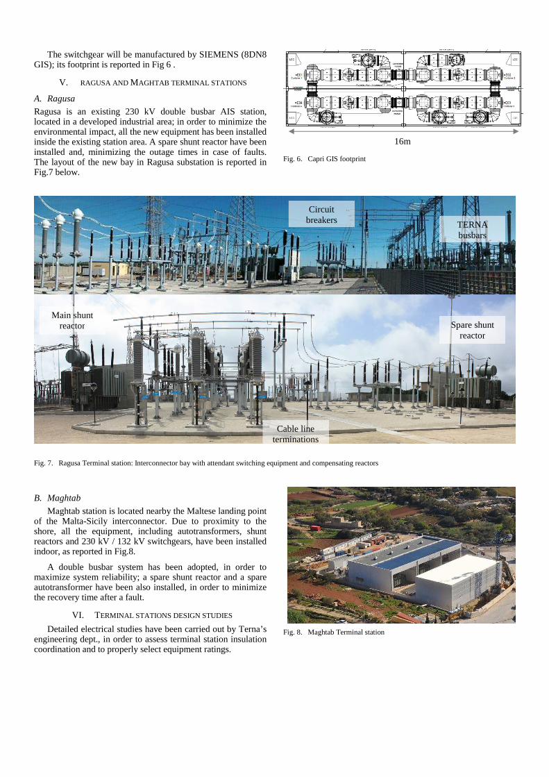
A. Ragusa
Ragusa is an existing 230 kV double busbar AIS station, located in a developed industrial area; in order to minimize the environmental impact, all the new equipment has been installed inside the existing station area. A spare shunt reactor have been installed and, minimizing the outage times in case of faults. The layout of the new bay in Ragusa substation is reported in Fig.7 below.
Fig. 6. Capri GIS footprint
Fig. 7. Ragusa Terminal station: Interconnector bay with attendant switching equipment and compensating reactors
B. Maghtab
Maghtab station is located nearby the Maltese landing point of the Malta-Sicily interconnector. Due to proximity to the shore, all the equipment, including autotransformers, shunt reactors and 230 kV / 132 kV switchgears, have been installed indoor, as reported in Fig.8.
A double busbar system has been adopted, in order to maximize system reliability; a spare shunt reactor and a spare autotransformer have been also installed, in order to minimize the recovery time after a fault.
VI. TERMINAL STATIONS DESIGN STUDIES
Detailed electrical studies have been carried out by Terna’s engineering dept., in order to assess terminal station insulation coordination and to properly select equipment ratings.
Fig. 8. Maghtab Terminal station
16m
TERNA busbars
Main shunt reactor
Cable line terminations
Circuit breakers
Spare shunt reactor

As stated above, circuit breakers are the most stressed component of an HVAC link, due the large capacitive current of the submarine cables. Capacitive current switching is a challenging task for HV circuit breakers; standard test values for cable charging current switching are 160 A and 250 A [7], respectively for 170 kV and 245 kV class circuit breakers. Under this constraint the maximum length for an uncompensated cable line is:
⋅= −
3
tanh"
1
1
1
r
ccMax U
k
ZI
KL (1)
Being K” the imaginary part of line propagation constant, k1, the earth fault factor, Ic the circuit breaker rated cable-charging breaking current, Zc the cable line characteristic impedance, Ur, the circuit breaker rated voltage.
Considering typical capacitance values for XLPE insulated HV submarine cable lines (c=0.18 ÷ 0.25 µF/km), the maximum length for a 150 or 230 kV, 50 Hz uncompensated cable line is about 20 ÷ 30 km.
As regards the Italy-Capri link, its charging current only slightly exceeds the rated switching current of 170 kV class circuit breaker: the most challenging operating condition is during single phase to ground faults on the cable line: the voltages and the cable charging current on the sound phases is increased by k due to the earth fault factor [8], which can be conservatively assumed to be k=1.4.
A single 37 Mvar shunt reactor has thus been chosen for compensating the submarine cable line. Due to space limitation in Capri, the shunt compensation will be installed at the mainland end of the link.
The Malta-Sicily interconnector clearly exceeds the above stated limit: the reactive power compensation sizing process is extensively described in [6]; detailed electrical studies have been addressed in [9].
In both cases, the high resulting (over 90%) shunt compensation degree is likely to cause zero missing phenomenon, if proper countermeasures are not applied [10]. Since 2011, Terna has successfully applied point-on-wave switching of compensated cable lines, with shunt reactor directly connected to the cable line itself.
This operation has been described to cause significant transient overvoltages [11] and to be effective only up to a 75% compensation degree [12].
Theoretically, for a typical accuracy of point-of-wave controller ∆t=1 ms, the maximum shunt compensation degree qmax which does not cause zero missing can be estimated as:
%4.76
10sin1
1 =⋅∆+=
ms
tqMax π (2)
If the shunt compensation degree q exceeds qmax, then the fi rst zero crossing delay can be estimated as:
ms
tq
qt
10sin
1ln0 πτ
⋅∆⋅
−−= (3)
The time constant τ can be evaluated as:
( )Rd
R
RRf
X
+=
πτ
2 (4)
Being XR and RR the shunt reactor reactance and resistance, and Rd the equivalent network resistance. For both Capri and Malta links, the theoretical delay for current zero crossing is about 0.5 s.
Terna’s experience however shows that in practice, due to additional losses and harmonic current, zero crossing occurs significantly before t0. Field tests, described in the following section, clearly show the effectiveness of the proposed solution.
Other solutions, such as pre-insertion resistors or additional circuit breakers for shunt reactor connection to the cable line [11], have not been considered, due to negative reliability impact of those additional components.
As regards insulation coordination issues, proper choice of line arresters furthermore allows for safe mitigation of switching overvoltages [10],[12].
VII. COMMISSIONING AND TESTING
At present time, the Italy-Capri link is still under construction: the submarine cable line has been installed, but the terminal stations construction is still in progress; only factory tests have been, so far, performed.
Final tests on the Malta-Sicily link started in January 2015; the link started commercial operation in April 2015; besides conventional high voltage tests, special tests have been carried out, in order to assess the impedance of the submarine cable line at 50 Hz and higher frequencies. Results, summarized in Fig.9, show that the first resonant frequency is about 375 Hz (around 7th harmonic); impedance magnitude at first resonant frequency is about 180 Ω.
Fig. 9. Malta-Sicily submarine cable: measured positive sequence short circuit impedance

Point-on-wave circuit breaker controllers testing has been another critical test activity, due to their paramount importance during cable line energization. The aim of these tests has been to verify that the closing times of each circuit breaker pole fulfill the severe requirement of 1 ms error margin.
At first, the cable line has been disconnected from the bay, for energizing the only shunt reactor, in order to avoid harmonic resonances in case of excessive closing times errors during the test activities: during point on wave controller testing it is necessary to carry out some switching manoeuvres before the arcing times are correctly identified and significant closing times error can arise before the calibration procedure is completed.
Once the point-on-wave controller calibration has been successfully carried out, the link has been energized from the Sicilian side. As visible in Fig. 10, zero missing effect does not appear, thanks to the correct circuit breaker operation.
Fig. 10. Current at the Sicilian (sending) end of the link, during cable energization
Due to the distributed nature of the submarine cable line, travelling current waves appear, thus ensuring zero crossing on all the three phases, notwithstanding the high compensation degree (attaining 98%) and the attendant extremely low steady state 50 Hz current.
Phase voltages at the receiving end of the link during energization manoeuvre are reported in Fig. 11; the measured switching overvoltage is about 1.9 p.u. i.e. 375 kV, significantly lower than the equipment SIWL (750 kV); no harmonic overvoltages arise.
Fig. 11. Phase to ground voltages in Maghtab, during cable energization
VIII. CONCLUSIONS
Terminal station design for long HVAC submarine cable links has to cope with challenging constraints, both from the technical and environmental point of view. The two considered links are the largest HVAC links in the Mediterranean sea commissioned in the last years, and represent the state of the art as regards the interconnection of large island to the shore.
Innovative solutions such as Hybrid Switchgear or indoor GIS and transformer installation have been foreseen for overcoming environmental issues.
The choice of substation schemes has been dictated by available space limits and reliability targets. Spare components have been foreseen, whenever possible; alternative solutions, such as equipment oversizing, have been implemented in order to cope with N-1 security criterion when spare components (most significantly shunt reactors) installation was not possible.
Field tests show that use of point-on-wave switching allows to counteract both zero missing phenomenon and temporary harmonic overvoltages, without causing significant switching overvoltages.
REFERENCES [1] “Guasto alla centrale elettrica: black-out lascia al buio Capri”, La
Repubblica, August 13th, 2009
[2] “Nuovo blackout a Capri, il sindaco accusa la Sippic”, La Repubblica, October 2nd, 2009
[3] “Capri, sequestrata la centrale elettrica: 3 indagati. Prosegue erogazione energia”, Il Mattino, March 25th, 2010
[4] C. Calleja, “Malta-wide blackout as aging plant trips again”, Times of Malta, Mar. 23, 2010
[5] Giannuzzi, G.M.; Palone, F.; Rebolini, M.; Vassallo, J.; Zaottini, R., “The Malta-Sicily EHV-AC interconnector”, Power Generation, Transmission, Distribution and Energy Conversion (MEDPOWER 2012), 8th Mediterranean Conference on, Cagliari, 1-3 Oct. 2012
[6] S. Lauria, F.Palone, “Optimal Operation of Long Inhomogeneous AC Cable Lines: The Malta–Sicily Interconnector”, Power Delivery, IEEE Transactions on, Vol. 29, Issue 3, 06/2014
[7] International Standard IEC 62271-100:2008 “High-voltage switchgear and controlgear - Part 100: Alternating current circuit-breakers”.
[8] International standard IEC 60071-2:2006 “Insulation co-ordination - Part 1: Definitions, principles and rules”
[9] F. Palone, M. Rebolini, S. Lauria, M. Schembari, J.P. Vassallo “Frequency domain studies for Malta-Sicily interconnector”, proc. Cigre 2014 general session, paper C4-305, Paris, August 28 2014.
[10] Techincal brochure TB 556 “Power system technical performance issues related to the application of long HVAC cables”, ELECTRA n. 270, October 2013.
[11] F. M. Faria da Silva, C. Leth Bak, U. S. Gudmundsdottir W. Wiechowski M. R. Knardrupgård, “Methods to Minimize Zero-Missing Phenomenon”, Power Delivery, IEEE Transactions on, Vol.25, Issue 4, Oct. 2010.
[12] U. S. Gudmundsdottir, Per B. Holst, “Solving Zero-Miss with Cable Energisation at Voltage Peak, Based on Insulation coordination Study Results”, proc.IPST 2013 conference, Vancouver, BC, Canada July 18-20, 2013
I_4_L I_8_L I_12_L
t/s0,100 0,125 0,150 0,175 0,200 0,225 0,250 0,275 0,300 0,325
I/ A
-1000
0
1000
VA VB VC
t/s-0,110 -0,100 -0,090 -0,080 -0,070 -0,060 -0,050
U/ V
-200000
0
200000