termo-blok termo-extra termo-blok ptv · 2.3. working with electronic control panels (option c and...
TRANSCRIPT

TRGOVINA TERMOSTROJ d.o.o. 10250 Lučko, F. Puškarića 1d Tel/Fax +385 1 6531-008, 6531-015, 6531-016 Eurposka unija
e-mail: [email protected] web: http://www.termostroj.com European Union
ELECTRIC BOILERS FOR CENTRAL HEATING
TERMO-Blok TERMO-Extra
TERMO-Blok PTV INSTRUCTIONS FOR USE
‘Ulaganje u budućnost’ ‘Investing for the future’
Projekt sufinancira Europska unija iz Europskog fonda za regionalni razvoj. Project is co-founded by the European Union’s Regional Development Fond.
INSTRUCTIONS FOR USE We reserve the right of alternations

TMS-UT-0114-T03-1
INSTRUCTIONS FOR USE We reserve the right of alternations

TMS-UT-0114-T03-1
Contents 1. Introduction ....................................................................................................................... 1
1.1. Applicable documents ................................................................................................. 1 1.2. Retention of documents .............................................................................................. 1 1.3. Introduction ................................................................................................................. 1 1.4. Heating curves ............................................................................................................ 1
1.4.1. Availability of heating curves................................................................................. 1 1.4.2. About heating curves ............................................................................................ 2 1.4.3. Why does the characteristic heating curve have to be set? .................................. 2 1.4.4. Corrections of the room temperature .................................................................... 2 1.4.5. Limiting the minimum and maximum temperature of the water in the boiler .......... 4
1.5. Functionality of hot domestic water ............................................................................. 4 1.5.1. Availability ............................................................................................................ 4 1.5.2. Description ........................................................................................................... 4
1.6. Frost protection ........................................................................................................... 5 1.6.1. Availability ............................................................................................................ 5 1.6.2. Domestic water ..................................................................................................... 5 1.6.3. Central heating ..................................................................................................... 5
2. Using control panels .......................................................................................................... 6 2.1. Working with standard control panel ........................................................................... 6 2.2. Working with electronic control panels (option E) ........................................................ 7 2.3. Working with electronic control panels (option C and W and Termo Blok PTV) ........... 8
2.3.1. General ................................................................................................................ 8 2.3.2. Central heating functions .....................................................................................11 2.3.3. Domestic water functions (control panel type 2)...................................................13 2.3.4. Central heating functions with heating curves disabled ........................................15
3. Maintenance .....................................................................................................................16 3.1. Periodic checking .......................................................................................................16 3.2. Cleaning.....................................................................................................................16 3.3. Central heating system ..............................................................................................16 3.4. Starting the pump manually .......................................................................................16
4. Survey of possible malfunctions and irregularities in operation .........................................18
INSTRUCTIONS FOR USE We reserve the right of alternations
TMS-UT-0114-T03-1
1. Introduction Thank you for your confidence you have shown to us by purchasing our central heating boiler. In order to use the boiler to the utmost correctly and safely, and above all economically, read thoroughly these instructions before continuing with installation. The appliances must be installed by a competent person, who is responsible for adhering to the existing regulations, rules and guidelines.
1.1. Applicable documents The following additional documents are provided with the appliance: For the owner of the system: Instructions for use Warranty card
For the qualified technician: Instructions for installation Electrical drawing for the appliance
1.2. Retention of documents Please pass on this installation manual to the owner of the system. The owner should retain the manuals so that they are available when required.
1.3. Introduction TERMO-Extra and TERMO-Blok are economical central heating boilers that may be used as an independent or additional source of heat. TERMO-Extra and TERMO-Blok boilers offer you the possibility, to reduce the power of a heater if necessary. The power may be switched on when necessary automatically with the built-in step regulator or manually with switches on the control board. In this way it is possible to adapt the boiler to the utmost to circumstances on the spot. The boiler operates on the principle of rapid heating smaller water quantities, so that exploiting of energy is already 100%. They are particularly suitable for heating smaller business premise, where you are short of space (small apartments, efficiency apartments, representation offices, smaller coffee-shop spaces etc.) or for heating larger spaces in early season when the main boiler is over dimensioned. TERMO-Extra boilers are manufactured only with upper connections. Temperature operation area is from 20 oC to 90 oC. TERMO-Extra and TERMO-Blok are designed in such a way that in apartment-contained central heating they can fit well with your furniture.
1.4. Heating curves 1.4.1. Availability of heating curves Use of heating curves, temperature compensation, is limited to Termo Extra boilers with options C and W, Termo Blok boilers with option C and Termo PTV boilers.
INSTRUCTIONS FOR USE We reserve the right of alternations page 1

TMS-UT-0114-T03-1
1.4.2. About Heating curves The modern way of heating is based on energy savings and automatic adjustments to worm up the space. To achieve the required temperature electric boiler with electronic control panel heats the water in the boiler automatically depending on the external temperature. There is no need to look after the minimal working temperature because electric boilers do not dew and that means that the temperature of the water in the boiler is at the same time the temperature in the heating elements (for example in radiators, convectors etc.). To achieve the desired room temperature, the characteristic heating curve has to be chosen depending on the characteristics of the object and the heating system.
Factory defined curves
If the heating curve is set optimally for heating your apartment or a house, corrections will not be necessary. 1.4.3. Why does the characteristic heating curve have to be set? After the first settings of the heating curve an authorized person can adjust, correct that curve if necessary. Every heating room is built up differently. Different heating elements and heating systems can be used (radiators, under floor heating or combined heating) and every building has a different thermal insulation. For the maximum exploitation of the heating and maximum energy savings, characteristic heating curve has to be set using the parameter on the control panel, in a way that the chosen heating curve is suitable for the heating system and for quality of the building. 1.4.4. Corrections of the room temperature Based on experience, factory settings of the device are for the average insulated object and room temperature of 22oC. If factory settings are not adequate for achieving the desired room temperature, supplemental adjustments of the standard heating curves can be made. Changing the inclination When changing the heating curve, inclination is changing too, and that way temperature of the water in the boiler is changing when the external temperature is low (below + 5oC). Level changes - offset By offsetting the heating curve for the chosen value, the temperature of the water in the boiler is changing without changing the shape of the curve.
INSTRUCTIONS FOR USE We reserve the right of alternations page 2

TMS-UT-0114-T03-1
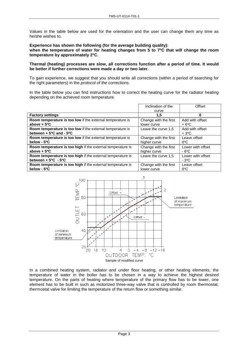
Values in the table below are used for the orientation and the user can change them any time as he/she wishes. The experience has shown the following (for the average building quality): when the temperature of the water for the heating changes from 5 to 7oC that will change the room temperature by approximately 2oC. Thermal (heating) processes are slow, all corrections function after some period of time. It would be better if further corrections were made a day or two later. To gain experience, we suggest that you should write all corrections (in the period of searching for the right parameters) in the protocol of the corrections. In the table below you can find instructions how to correct the heating curve for the radiator heating depending on the achieved room temperature. Inclination of the
curve Offset
Factory settings 1,5 0 Room temperature is too low if the external temperature is above + 5oC
Change with the first lower curve
Add with offset + 6oC
Room temperature is too low if the external temperature is between + 5oC and - 5oC
Leave the curve 1,5 Add with offset + 3oC
Room temperature is too low if the external temperature is below - 5oC
Change with the first higher curve
Leave offset 0oC
Room temperature is too high if the external temperature is above + 5oC
Change with the first higher curve
Lower with offset - 6oC
Room temperature is too high if the external temperature is between + 5oC - 5oC
Leave the curve 1,5 Lower with offset - 3oC
Room temperature is too high if the external temperature is below- 5oC
Change with the first lower curve
Leave offset 0oC
Sample of modified curve
In combined heating system, radiator and under floor heating or other heating elements, temperature of the water in the boiler has to be chosen in a way to achieve the highest desired temperature. On the parts of heating where temperature of the primary flow has to be lower, one element has to be built in such as motorized three-way valve that is controlled by room thermostat, thermostat valve for limiting the temperature of the return flow or something similar.
INSTRUCTIONS FOR USE We reserve the right of alternations page 3

TRGOVINA TERMOSTROJ d.o.o. 10250 Lučko, F. Puškarića 1d Tel/Fax +385 1 6531-008, 6531-015, 6531-016 Eurposka unija
e-mail: [email protected] web: http://www.termostroj.com European Union 1.4.5. Limiting the minimum and maximum temperature of the water in the boiler If the heating curves and offset are selected correctly and the room temperature is falling, in transitional period in heating seasons (fall, spring) minimal temperature of the water in the boiler has to be changed. If the building cannot accumulate heat (sudden and short worming during the day) the necessary temperature of water in the boiler will be too low and will not keep up the desired room temperature. Limitation of the maximum temperature of water in the boiler serves more as a protection. Factory setting is 90oC, and we suggest lowering it to approximately 80oC. Limitation of the maximum temperature of water in the boiler is also used in central heating and domestic water preparation system, and because of that it is not advisable to lower that temperature too much because the domestic water will warm up slowly on higher temperatures.
1.5. Functionality of hot domestic water 1.5.1. Availability Termo Extra boilers with options W, and Termo PTV boilers enable the preparation of hot water in separate water storage with heat exchanger. 1.5.2. Description Domestic water conditioning has the preference order over central heating. At the moment of signaling the need for warming up the domestic water container by the domestic water temperature sensor, the circulation pump of central heating is switched off, and the circulation pump for domestic water conditioning is switched on. Heaters regulate the desired water temperature in the boiler that is 25°C higher than set values of the desired domestic water temperature (independent of central heating curve). Circulation pump for domestic water conditioning supplies the container until the desired temperature of domestic water is reached, upon which it is switched off with previously described and programmed time delay. If the central heating is off, either floor or radiators’ heating, at the moment of reaching the desired domestic water temperature, the desired water temperature in the boiler is set to minimum value of water temperature in the boiler (stand by). At repeated requests for heating the domestic water container, the desired water temperature in the boiler is set to 25°C higher than set values of the desired domestic water temperature. Circulation pump for domestic water conditioning is switched on as late as the water temperature in a boiler reaches the same or higher temperature than desired value of domestic water temperature. The 5°C difference for warm water conditioning is programmed. It means that if the desired temperature of domestic water tank is 60°C, then the central heating will be switched off and domestic water conditioning switched on as late as domestic water temperature is lower than 55°C, and heating will be switched on and domestic water conditioning switched off when the temperature in domestic water tank reaches 60°C, and when the programmed time of supplemental operation of domestic water circulation pump has passed. If the time for domestic water conditioning is longer than 30 minutes, i.e. if the desired temperature of domestic water tank is not reached within 30 minutes, the process will be automatically interrupted and switched to the heating regime, which in this case lasts at least 30 minutes.
INSTALACIJSKE UPUTE Zadržavamo pravo izmjene uputa bez posebne najave

TRGOVINA TERMOSTROJ d.o.o. 10250 Lučko, F. Puškarića 1d Tel/Fax +385 1 6531-008, 6531-015, 6531-016 Eurposka unija
e-mail: [email protected] web: http://www.termostroj.com European Union
1.6. Frost protection 1.6.1. Availability Frost protection, as boiler’s function, is limited to Termo Extra boilers with options E, C and W, Termo Blok boilers with option C and Termo PTV boilers. For other versions of boilers, frost protection can be provided with the usage of an appropriate room thermostat. Where frost protection is controlled by room thermostat, please consult room thermostat manuals for more details. Following topics explain how frost protection is working when it is boiler controlled function (options C,W). 1.6.2. Domestic water If the boiler is on for supply and only warm water conditioning is on or only heating or both, the protection from freezing the water in warm water container switches on automatically when the temperature sensor of warm water container reads the value below 7°C, signaling switching on by blinking display, as well as the LED diode of the heater and warm water conditioning, regulating the warm water container temperature to 7°C. 1.6.3. Central heating If the boiler is on for supply and heating or both (heating and warm water conditioning) are off, the protection from freezing the water in the central heating system switches automatically on if the water temperature sensor in the boiler reads the value below 8°C. In this case the temperature of water in the boiler is maintained at 8°C, as long as the conditions of possible freezing do not disappear. Switching on is signaled by a blinking display as well as the LED diode of the heater and the boiler. In this case, domestic water conditioning has priority. In order for the freezing protection system of central heating to operate, the room thermostat should be in the position of freezing protection as well (otherwise, the circulation pump of central heating would not operate).
INSTALACIJSKE UPUTE Zadržavamo pravo izmjene uputa bez posebne najave

TRGOVINA TERMOSTROJ d.o.o. 10250 Lučko, F. Puškarića 1d Tel/Fax +385 1 6531-008, 6531-015, 6531-016 Eurposka unija
e-mail: [email protected] web: http://www.termostroj.com European Union
2. Using control panels
2.1. Working with standard control panel
Standard electromechanical control panel
The automatics consists of the following elements: 1 – Indicator of temperature /pressure in boiler 2 – Working thermostat 3 – Switch for the 2nd and 3rd operation stage 4 – Cutout thermostat with manual deactivation (switches off on ca 115 oC) 5 – Indicator of air appearance in the boiler - air-indicator (also indicates low voltage protection) 6 - Switch for ON/OFF and the 1st heating stage 7 – Fuse 2,5A protecting the pump and switches 8 – Indication of heater operation 9 - Indicates low voltage protection - under 180V Putting on central heating By switching the switch (6) ON, the central heating system is switched on and the first power stage is active. With switch (3) it is possible to control manually the second or the third power stage of boiler. Boilers with 3 stages have soft start for the second and the third stage and switches (3) have only limiting function. If the boiler is heating, the light of heater in operation (8) is on, if heaters are not working and boiler is in standby only ON/OFF light is on. Adjustment of desired temperature of central heating With the help of working thermostat (2) it is possible to select the fixed desired temperature in boiler. Working thermostat has range from 20ºC to 80ºC. Recommended temperature is about 60ºC (12 o’clock position). Air in the boiler (5), red light If the air appears in the boiler, the signalization of air in the boiler turns on (5) and the boiler stops the operation. In this way the boiler is protected against burning through due to presence of air. To continue the operation the boiler should be vented. If the boiler is correctly vented, the operation of boiler continues automatically. Voltage drop (9), red light If the voltage in the network line drops below 180V by phase, the signalization of under voltage protection (9) turns on, the boiler automatically switches off in order to protect electronics and
INSTALACIJSKE UPUTE Zadržavamo pravo izmjene uputa bez posebne najave

TRGOVINA TERMOSTROJ d.o.o. 10250 Lučko, F. Puškarića 1d Tel/Fax +385 1 6531-008, 6531-015, 6531-016 Eurposka unija
e-mail: [email protected] web: http://www.termostroj.com European Union contactors inside the boiler. The boiler will automatically continue the operation when the network voltage reaches values above 180V. Cutout thermostat - turning on Cutout thermostat (safety thermostat) (4) protects the boiler against rapid increase of temperature above 115°C. The fuse turns the boiler off and ejects the RCCB (RCD)-switch. For boiler to continue working it is necessary to take off the protection cover from the cutout thermostat and press the red key, upon which the RCCB (RCD)-switch should be switched on again. NOTE: If the room thermostat is on, make sure that it is set on the required room temperature and if supply batteries are in order, otherwise the boiler will not operate.
2.2. Working with electronic control panels (option E)
Electronic control panel without external temperature compensation
1. Multipurpose – temperature indicator (temperature of boiler,
adjustment of temperature)
2. Signalization of operation degree of heaters (1, 2, 3)
3. Signalization of the presence of air in the boiler (red light)
4. Signalization of under voltage protection (red light)
5. Signalization of boiler operation (green light)
6. Adjustment of temperature in boiler
7. Switch for central heating switching on and off
8. Thermal fuse
Switching on of central heating By switching the switch (7) to the position 1, the central heating system is switched on. Upon switching on the desired water temperature in boiler is displayed for 5 seconds, signalization of boiler operation is twinkling (5). After 5 seconds the real temperature in the boiler is displayed (1); if the current temperature in the boiler meets the desired one, the signalization lamp of the boiler operation (5) is switched off. Adjustment of desired temperature of central heating By pressing the key for temperature adjustment (6) the desired temperature in the boiler appears, the signalization lamp of the boiler operation (5) is twinkling. By repeated pressing upwards or downwards it is possible to increase or decrease the desired sanitary water temperature. When the temperature is
INSTALACIJSKE UPUTE Zadržavamo pravo izmjene uputa bez posebne najave
TRGOVINA TERMOSTROJ d.o.o. 10250 Lučko, F. Puškarića 1d Tel/Fax +385 1 6531-008, 6531-015, 6531-016 Eurposka unija
e-mail: [email protected] web: http://www.termostroj.com European Union adjusted it is sufficient to wait for 5 seconds (signalization lamp of the boiler operation (5) does not twinkle) in order for the boiler to memorize new temperature. Air in the boiler (3), red light If air appears in the boiler, the signalization of air in the boiler turns on (3) and the boiler stops the operation. In this way the boiler is protected against burning through because of appearance of air. To continue the operation, the boiler should be vented. If the boiler is correctly vented, the operation of boiler continues automatically. Voltage drop (4), red light If the voltage in the network line drops below 180V by phase, the signalization of under voltage protection (4) turns on, the boiler automatically switches off in order to protect electronics and contactors inside the boiler. The boiler will automatically continue the operation when the network voltage reaches values above 180V. Cutout thermostat - turning on Cutout thermostat (safety thermostat) (8) protects the boiler against rapid increase of temperature above 115°C. The fuse turns off the boiler and ejects the RCCB (RCD)-switch. To continue the operation it is necessary to take off the protection cover from the cutout thermostat and press the red key, after which the RCCB (RCD)-switch should be switched on again.
2.3. Working with electronic control panels (option C and W and Termo Blok PTV)
2.3.1. General Regardless of the selected regulation curve, the maximum water temperature in the boiler is limited to 90°C for radiator heating and 50°C for floor heating. Factory setting of the curve is 1,5 for radiator heating. Factory setting of the curve is 0,6 for under floor heating. Refer to chapter 1.4. for detailed description of heating curves. Refer to chapter 1.5. for detailed description of DHW functions. Refer to chapter 1.6. for detailed description of frost protection. Refer to chapter 4.8 for detailed description of selecting desired set of heating curves.
INSTALACIJSKE UPUTE Zadržavamo pravo izmjene uputa bez posebne najave
TRGOVINA TERMOSTROJ d.o.o. 10250 Lučko, F. Puškarića 1d Tel/Fax +385 1 6531-008, 6531-015, 6531-016 Eurposka unija
e-mail: [email protected] web: http://www.termostroj.com European Union
!
4 0bar
0
I
OKAIR
U<
12 1 2 3
4
5
52
2
6711
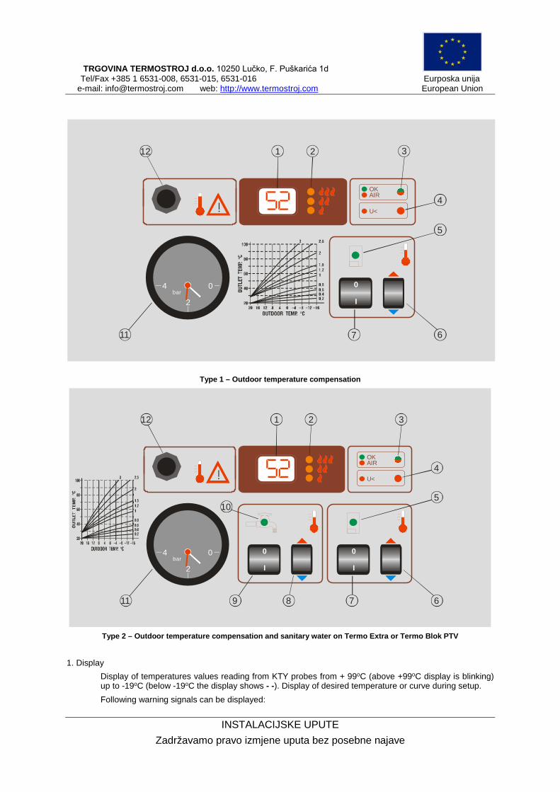
Type 1 – Outdoor temperature compensation
!
4 0
2bar
0
I
0
I
OKAIR
U<
12 1 2 3
4
5
6789
10
11
52
Type 2 – Outdoor temperature compensation and sanitary water on Termo Extra or Termo Blok PTV
1. Display
Display of temperatures values reading from KTY probes from + 99oC (above +99oC display is blinking) up to -19oC (below -19oC the display shows - -). Display of desired temperature or curve during setup. Following warning signals can be displayed:
INSTALACIJSKE UPUTE Zadržavamo pravo izmjene uputa bez posebne najave
TRGOVINA TERMOSTROJ d.o.o. 10250 Lučko, F. Puškarića 1d Tel/Fax +385 1 6531-008, 6531-015, 6531-016 Eurposka unija
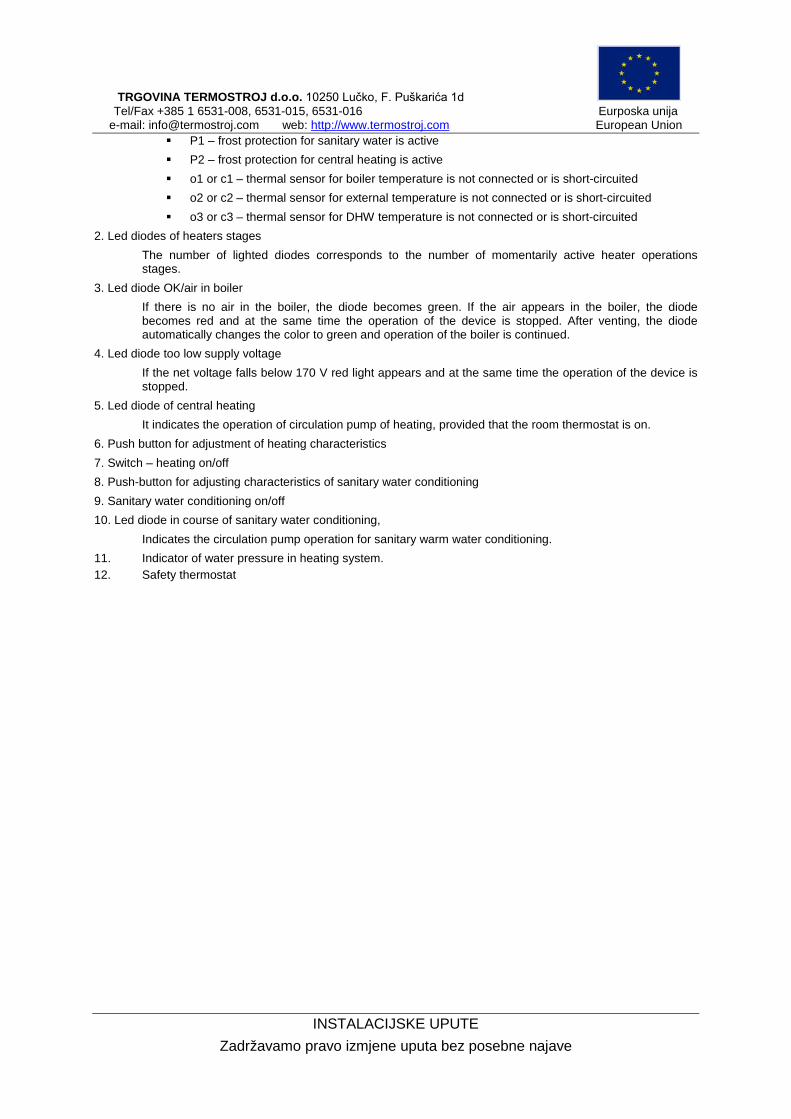
e-mail: [email protected] web: http://www.termostroj.com European Union P1 – frost protection for sanitary water is active P2 – frost protection for central heating is active o1 or c1 – thermal sensor for boiler temperature is not connected or is short-circuited o2 or c2 – thermal sensor for external temperature is not connected or is short-circuited o3 or c3 – thermal sensor for DHW temperature is not connected or is short-circuited
2. Led diodes of heaters stages The number of lighted diodes corresponds to the number of momentarily active heater operations stages.
3. Led diode OK/air in boiler If there is no air in the boiler, the diode becomes green. If the air appears in the boiler, the diode becomes red and at the same time the operation of the device is stopped. After venting, the diode automatically changes the color to green and operation of the boiler is continued.
4. Led diode too low supply voltage If the net voltage falls below 170 V red light appears and at the same time the operation of the device is stopped.
5. Led diode of central heating It indicates the operation of circulation pump of heating, provided that the room thermostat is on.
6. Push button for adjustment of heating characteristics 7. Switch – heating on/off 8. Push-button for adjusting characteristics of sanitary water conditioning 9. Sanitary water conditioning on/off 10. Led diode in course of sanitary water conditioning,
Indicates the circulation pump operation for sanitary warm water conditioning. 11. Indicator of water pressure in heating system. 12. Safety thermostat
INSTALACIJSKE UPUTE Zadržavamo pravo izmjene uputa bez posebne najave

TRGOVINA TERMOSTROJ d.o.o. 10250 Lučko, F. Puškarića 1d Tel/Fax +385 1 6531-008, 6531-015, 6531-016 Eurposka unija
e-mail: [email protected] web: http://www.termostroj.com European Union 2.3.2. Central heating functions
>5 sec0.6
41 >5 sec
>10 sec
>5 sec 3
32
>5 sec
<5 sec
>15 sec
>5 sec 90
>20 sec 60 32>5 sec
Display of desired temperature inside the boiler By pressing the key (6) user can see the desired temperature inside the boiler.(calculated from the selected correction curve) The Display shows the desired temperature of water in the boiler. The value is displayed for 5 s, after which display normally shows the real temperature of water in the boiler.
Correction curve selection By pressing the key (6) user can enter curve selection menu. The number of set curve is blinking, according to which the correction of water temperature in the boiler is corrected in relation to external temperature. Values are between 1 and 3 or 0,2 and 0,9. Curves between 1 and 3 are for radiators’ central heating and curves 0,2 to 0,9 are for under floor heating. By pressing the key, numbers of curves are changing with the step of 0,1 within the set, according to the diagram on the front plate. If the key is held pressed less than 5 s the display value becomes valid regulation curve.
Limiting maximum boiler power By pressing the key (6) user can limit the power level. By pressing the key it is possible to select 1 2 or 3 as number of available power levels. If the key is held pressed less than 5 s the selected power level mode will become active. Boilers from 6 to 16 kW have only two power levels.
Limiting maximum temperature inside the boiler By pressing the key (6) user can limit maximum temperature inside the boiler. Factory defined maximum temperature starts to blink. By pressing up or down user can set new maximum temperature. If the key (6) is held pressed less than 5 s the selected maximum temperature will become active. This temperature represents maximum temperature that can be achieved regardless of selected curve.
Manual selection of desired temperature inside the boiler By pressing the key (6) user can set temperature in the boiler, regardless of previously selected curve. Desired temperature starts to blink. By pressing the key up or down user can select fixed temperature in the boiler. If the key is held pressed less than 5 s the fixed temperature becomes active. When boiler is in fixed temperature mode, the LED display blinks while displaying current temperature in the boiler. User can just press the key (6) up or down for next change of fixed temperature. When boiler is in fixed temperature mode, all correction curves are disregarded. To return to the correction curve mode, the boiler must be switched off and back on using ON/OFF switch.
INSTALACIJSKE UPUTE Zadržavamo pravo izmjene uputa bez posebne najave

TRGOVINA TERMOSTROJ d.o.o. 10250 Lučko, F. Puškarića 1d Tel/Fax +385 1 6531-008, 6531-015, 6531-016 Eurposka unija
e-mail: [email protected] web: http://www.termostroj.com European Union Continuation...
>5 sec 0
-1 >5 sec
>10 sec
>5 sec20
32
>5 sec
<5 sec
>15 sec1.4
Display of external temperature By pressing the key (6) user can see external temperature. The Display shows the external temperature. The value is displayed for 5 s, after which the display normally shows the real temperature of water in the boiler.
Offset of currently selected correction curve By pressing the key (6) user can enter the curve selection menu. The LED display will show current offset in ˚C. Offset does not affect maximal or minimal temperature, they are set in absolute values By pressing the key (6) it is possible to change offset in steps of 1˚C. Factory setting is 0˚C. Offset range is from –9 to +20˚C. If the key is held pressed less than 5 s the displayed value becomes valid offset in ˚C.
Setting the minimal temperature inside the boiler By pressing the key (6) user can select minimal temperature inside the boiler. Minimal temperature starts blinking. Factory setting is 27°C for radiator heating. Factory setting is 20°C for under floor heating. By pressing the key user can select the desired temperature in range from 10 to 50°C. Temperature changes in steps of 1°C. If the key is held pressed less than 5 s the value from the display becomes the desired minimal boiler temperature.
Displaying software version and factory reset By pressing the key (6) longer than 15 seconds, the LED will show the software version and the factory reset of central heating parameters will occur.
INSTALACIJSKE UPUTE Zadržavamo pravo izmjene uputa bez posebne najave
TRGOVINA TERMOSTROJ d.o.o. 10250 Lučko, F. Puškarića 1d Tel/Fax +385 1 6531-008, 6531-015, 6531-016 Eurposka unija
e-mail: [email protected] web: http://www.termostroj.com European Union 2.3.3. Domestic water functions (control panel type 2)
>5 sec50
50 >5 sec
>10 sec
32
>5 sec
<5 sec
1.4
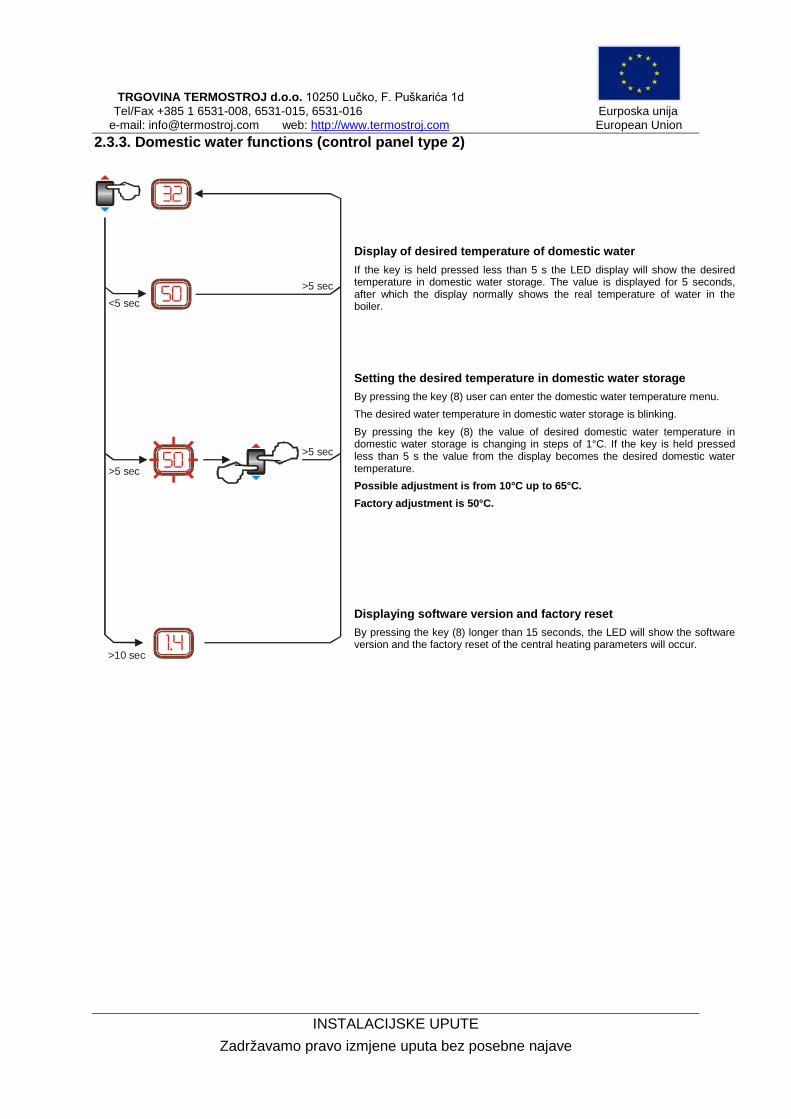
Display of desired temperature of domestic water If the key is held pressed less than 5 s the LED display will show the desired temperature in domestic water storage. The value is displayed for 5 seconds, after which the display normally shows the real temperature of water in the boiler.
Setting the desired temperature in domestic water storage By pressing the key (8) user can enter the domestic water temperature menu. The desired water temperature in domestic water storage is blinking. By pressing the key (8) the value of desired domestic water temperature in domestic water storage is changing in steps of 1°C. If the key is held pressed less than 5 s the value from the display becomes the desired domestic water temperature. Possible adjustment is from 10°C up to 65°C. Factory adjustment is 50°C.
Displaying software version and factory reset By pressing the key (8) longer than 15 seconds, the LED will show the software version and the factory reset of the central heating parameters will occur.
INSTALACIJSKE UPUTE Zadržavamo pravo izmjene uputa bez posebne najave

TRGOVINA TERMOSTROJ d.o.o. 10250 Lučko, F. Puškarića 1d Tel/Fax +385 1 6531-008, 6531-015, 6531-016 Eurposka unija
e-mail: [email protected] web: http://www.termostroj.com European Union Continuation...
>5 sec1.0
36 >5 sec
>10 sec
>5 sec20
32
>5 sec
<5 sec
>15 sec1.4
Display of current temperature in domestic water storage By pressing the key (8) user can select the display of current temperature in the domestic water storage. The value is displayed for 5 s, after which the display normally shows the real temperature of water in the boiler.
Setting additional working time of domestic water pump By pressing the key (8) user can setup additional working time of domestic water pump. The time of supplemental operation of circulation pump operation for domestic water conditioning is blinking. By pressing the key the time is changing from 0,1 min up to 19 min. with the step of 1 digit. If the key is held pressed less than 5 s, the value from a display becomes valid time of supplemental operation of circulation pump for domestic warm water conditioning. Factory setting is 1 min.
Setting stand by temperature inside boiler By pressing the key (8) user can setup stand by temperature inside the boiler. The LED will show current standby temperature inside the boiler. Pressing the key (8) will change standby temperature in range from 10°C to 50°C by 1°C. If the key is held pressed less than 5 s the value from the display becomes the valid standby temperature inside the boiler.
Displaying software version and factory reset By pressing the key (8) longer than 15 seconds, the LED will show the software version and the factory reset of central heating parameters will occur.
INSTALACIJSKE UPUTE Zadržavamo pravo izmjene uputa bez posebne najave

TRGOVINA TERMOSTROJ d.o.o. 10250 Lučko, F. Puškarića 1d Tel/Fax +385 1 6531-008, 6531-015, 6531-016 Eurposka unija
e-mail: [email protected] web: http://www.termostroj.com European Union 2.3.4. Central heating functions with heating curves disabled
>5 sec4 1
4 1 >5 sec
>10 sec
>5 sec 3
32
>5 sec
<5 sec
Display of desired temperature in boiler If the key (6) is held pressed less than 5 s the LED display will show the desired temperature in the boiler. The value is displayed for 5 seconds, after which the display normally shows the real temperature of water in the boiler.
Setting of the desired temperature in the boiler By pressing the key (6) user can enter the boiler temperature menu. The desired boiler temperature is blinking. By pressing the key (6) UP or DOWN, the desired boiler temperature can be set in steps of 1°C. If the key is held pressed less than 5 s the value from the display becomes the desired boiler temperature. Possible adjustment is from 20°C up to 90°C for radiator heating. Possible adjustment is from 15°C up to 45°C for under floor heating.
Limiting maximum power of the boiler By pressing the key (6) user can limit the power level. By pressing the key it is possible to select 1 2 or 3 as number of the available power levels. If the key (6) is held pressed less than 5 s the selected power level mode will become active. Boilers from 6 to 16 kW have only two power levels.
INSTALACIJSKE UPUTE Zadržavamo pravo izmjene uputa bez posebne najave
TRGOVINA TERMOSTROJ d.o.o. 10250 Lučko, F. Puškarića 1d Tel/Fax +385 1 6531-008, 6531-015, 6531-016 Eurposka unija
e-mail: [email protected] web: http://www.termostroj.com European Union
3. Maintenance
3.1. Periodic checking We recommend the inspection of the device once a year by the authorized service provider (before heating season). This service is not included in the warranty. During the inspection all electric and water connections should be tightened, the system should be vented and – if necessary – filled up, valves and general functionality of the device should be checked. RCCD switch - pressing the TEST button must disconnect the RCCD switch. This testing procedure insures that switch is functioning properly. We recommend this test once or twice in heating season. Safety thermostat – we recommended to check safety thermostat before every heating season by heating up the sensor with heating fan or lighter over 100°C must actuate overheating protection by switching off the RCCD switch. Safety valve should be checked once a year (before the beginning of heating season) to ensure proper functioning and avoiding appearance of water calculus. If the boiler is not connected to the room thermostat or if the boiler is out of function during the winter time, there is a danger of installation freezing. In this case the system should be filled with antifreeze liquid for central heating, and if this is not possible water should be drained out.
3.2. Cleaning It is not permitted to use aggressive media (e.g. gasoline, kerosene or solvent) for cleaning the product. Media for cleaning plastics or dishwashing media can be used for the external shell and decorative cover. Control panel should be cleaned with dry or moist cloth (not wet).
3.3. Central heating system If the boiler is not connected to the room thermostat (Termo boilers without C or W option), or if the boiler is out of function during wintertime, there is a danger of installation freeze. In this case the system should be filled with antifreeze liquid for central heating, if this is not possible water should be drained out of the system with the help of charge and discharge. The recommended pressure of central heating installation is 0,15 mpa (1,5 bar), the maximum pressure is 0,25 mpa (2,5 bar).
3.4. Starting the pump manually In order to access the pump, remove the front cover of the boiler as described below. In most cases steps 1 and 2 are sufficient.
INSTALACIJSKE UPUTE Zadržavamo pravo izmjene uputa bez posebne najave

TRGOVINA TERMOSTROJ d.o.o. 10250 Lučko, F. Puškarića 1d Tel/Fax +385 1 6531-008, 6531-015, 6531-016 Eurposka unija
e-mail: [email protected] web: http://www.termostroj.com European Union
Grasp the front case by its sides, pull it towards the front and remove it by lifting it off the unit, push the top cover backwards and lift it of the unit. To start the pump it is necessary to turn off the protection plug on its front side (1), below which there is an axis with the groove for screwdriver. Using the screwdriver, the pump (2) should be turned several times in the direction of the arrow on the pump head and the boiler should be put on again.
When the pump starts the operation the temperature of water in the boiler and the temperature of sanitary water should be selected. The optimal temperature for central heating is between 60 and 70°C. If the room thermostat is connected to the boiler, the desired room temperature should be adjusted according to the instructions of the producer of the room thermostat.
INSTALACIJSKE UPUTE Zadržavamo pravo izmjene uputa bez posebne najave

TRGOVINA TERMOSTROJ d.o.o. 10250 Lučko, F. Puškarića 1d Tel/Fax +385 1 6531-008, 6531-015, 6531-016 Eurposka unija
e-mail: [email protected] web: http://www.termostroj.com European Union
4. Survey of possible malfunctions and irregularities in operation
MALFUNCTION CAUSE ELIMINATION - there is no voltage on the control panel at switching on
- there is no power supply from the net on one or more phases
- fuse 2,5A on the control panel is burned through
- RCCB switch is disconnected
- replace fuse 2,5A and check the cause of burning
- contact authorized service personnel to resolve the problem
- By switching on, the switches on the control panel display the voltage, but the boiler does not heat
- check the adjustment of the room thermostat,
- limiting thermostat is activated - indicator of air presence in the boiler
blocked the operation, - defective switch, - operation thermostat is defective, - heaters are burned through
- check the set temperature on the room thermostat, replace batteries, or the room thermostat is faulty,
- deaerate the boiler in order to turn off the lamp “air in boiler”
- temperature in boiler is on desired value, but radiators do not heat
- circulation pump does not operate, - air stopper on central heating
installation prevents circulation
- start mechanical pump (CHAPTER 4.)
- deaerate installation
- boiler does not provide enough heat
- one phase is missing on supply - in two-stage thermostats the second
stage is not functioning - the second or the third stage is not
manually turned on, - one switcher is defective, - a part of heater is burned through - in a three-phase system the three
different phases are not brought to the boiler
- check fuses on the main panel,
- contact authorized service personnel to resolve the problem
- the switcher can be heard while operating (it buzzes)
radio and TV-interferences
- poor voltage in the net - defective switcher
- contact authorized service personnel to resolve the problem
- when turning on or off the operation thermostat, radio and TV-interferences occur
- defective operation thermostat, - defective blockade (RC – protection)
- contact authorized service personnel to resolve the problem
- boiler in operation “roars”
- the system is not well deaerated, - defective heater
- deaerate the system - contact authorized service
personnel to resolve problem
- pressure in the system varies
- defective expansion vessel, - the vessel pressure is too low or too
high
- contact authorized service personnel to resolve the problem
INSTALACIJSKE UPUTE Zadržavamo pravo izmjene uputa bez posebne najave

TRGOVINA TERMOSTROJ d.o.o. 10250 Lučko, F. Puškarića 1d Tel/Fax +385 1 6531-008, 6531-015, 6531-016 Eurposka unija
e-mail: [email protected] web: http://www.termostroj.com European Union - the actual temperature in the boiler is higher than the desired temperature and the safety thermostat is activated
- defective contactors - defective operation thermostat
- contact authorized service personnel to resolve the exact source of the problem
- RCCB switch disconnects
- defective heater, - humidity on conductors, - safety thermostat is activated
- check leakage, - contact authorized service
personnel to resolve the exact source of the problem
- RCCB switch cannot be reset
- safety thermostat is activated - pre-reset safety thermostat and then the RCCB switch
- contact authorized service personnel to resolve the exact source the of problem
‘Ulaganje u budućnost’ ‘Investing for the future’
Projekt sufinancira Europska unija iz Europskog fonda za regionalni razvoj. Project is co-founded by the European Union’s Regional Development Fond.
INSTALACIJSKE UPUTE Zadržavamo pravo izmjene uputa bez posebne najave
TRGOVINA TERMOSTROJ d.o.o. 10250 Lučko, F. Puškarića 1d Tel/Fax +385 1 6531-008, 6531-015, 6531-016 Eurposka unija
e-mail: [email protected] web: http://www.termostroj.com European Union
INSTALACIJSKE UPUTE Zadržavamo pravo izmjene uputa bez posebne najave

TRGOVINA TERMOSTROJ d.o.o. 10250 Lučko, F. Puškarića 1d Tel/Fax +385 1 6531-008, 6531-015, 6531-016 Eurposka unija
e-mail: [email protected] web: http://www.termostroj.com European Union
ELECTRIC BOILERS FOR CENTRAL HEATING
TERMO-Blok TERMO-Extra
TERMO-Blok PTV INSTRUCTIONS FOR INSTALLATION
‘Ulaganje u budućnost’ ‘Investing for the future’
Projekt sufinancira Europska unija iz Europskog fonda za regionalni razvoj. Project is co-founded by the European Union’s Regional Development Fond.
INSTRUCTIONS FOR INSTALLATION We reserve the right of alternations

TMS-UT-0114-T01-1
INSTRUCTIONS FOR INSTALLATION We reserve the right of alternations

TMS-UT-0114-T01-1
Contents 1. Introduction ....................................................................................................................... 1
1.1. Applicable documents ................................................................................................. 1 1.2. Retention of documents .............................................................................................. 1 1.3. Introduction ................................................................................................................. 1 1.4. Heating curves ............................................................................................................ 1
1.4.1. Availability of heating curves................................................................................. 1 1.4.2. About Heating curves ........................................................................................... 2 1.4.3. Why does the characteristic heating curve have to be set? .................................. 2 1.4.4. Corrections of the room temperature .................................................................... 2 1.4.5. Limiting the minimum and maximum temperature of water in the boiler ................ 4
1.5. Functionality of hot domestic water ............................................................................. 4 1.5.1. Availability ............................................................................................................ 4 1.5.2. Description ........................................................................................................... 4
1.6. Frost protection ........................................................................................................... 5 1.6.1. Avaliability ............................................................................................................ 5 1.6.2. Domestic water ..................................................................................................... 5 1.6.3. Central heating ..................................................................................................... 5
2. Boiler specifications ........................................................................................................... 6
2.1 Dimensions .................................................................................................................. 6 2.2 Expansion Vessel Characteristics (Termo Blok and Termo Blok TV Boilers) ...............10 2.3. Power supply characteristics 230V/400V ...................................................................10 2.4. Function elements of Termo boilers ...........................................................................11
3.0 General requirements .....................................................................................................14
3.1. Contents included in delivery .....................................................................................14 3.2 Preliminary remarks ....................................................................................................14 3.3. Recommendations for various installation types.........................................................15 3.4. Installation site ...........................................................................................................15
3.4.1. Position of a boiler ...............................................................................................15 3.4.2. Power supply .......................................................................................................16 3.5. System requirements ..............................................................................................16 3.5.1. Pipe work.............................................................................................................16 3.5.2. Cleansing and flushing the system ......................................................................16 3.5.3. Filling and preparing heating system ...................................................................17 3.5.4. Pressure relief valve ............................................................................................17 3.5.5. Pressure gauge ...................................................................................................17 3.5.6. Expansion vessel .................................................................................................17 3.5.7. Circulating pump..................................................................................................17 3.5.8. Venting ................................................................................................................17
4. Boiler installation sequence ..............................................................................................18
4.1. Transporting the appliance .........................................................................................18 4.2. Select position for boiler .............................................................................................18 4.3. Fitting the boiler hanging bracket ...............................................................................18 4.4. Removing/fixing the front and top case ......................................................................19 4.5. Pipe work connection .................................................................................................19 4.6. Power supply connection ...........................................................................................20 4.7. Connecting temperature sensors or external electrical controls .................................20
4.7.1. Accessing connection plate .................................................................................20 4.7.2. Connecting external temperature sensor .............................................................21 4.7.3. Connecting domestic hot water temperature sensor ............................................21
INSTRUCTIONS FOR INSTALLATION We reserve the right of alternations

TMS-UT-0114-T01-1
4.7.4. Connecting room thermostat and time switch ......................................................23 4.7.5. Connecting external pump on Termo Extra boilers ..............................................23
4.8. Selecting set of heating curves ..................................................................................24 4.9 Filling the heating system ........................................................................................24
5. Commissioning .................................................................................................................25
5.1. Central heating system check ....................................................................................25 5.2. Preliminary electrical check ........................................................................................25 5.3. Changing the speed of pump for central heating ........................................................25 5.4. Working with standard control panel ..........................................................................26 5.5. Working with electronic control panels (option E) .......................................................27 5.6. Working with electronic control panels (option C and W and Termo Blok PTV) ..........28
5.6.1. General ...............................................................................................................28 5.6.2. Central heating functions .....................................................................................30 5.6.3. Domestic water functions (control panel type 2)...................................................32 5.6.4. Central heating functions with heating curves disabled ........................................34 5.6.4.1 Access to special service menu .........................................................................35
5.7. Starting the pump manually .......................................................................................36 6. Maintenance .................................................................................................................36 6.1. Periodic checking .......................................................................................................36 6.2. Cleaning.....................................................................................................................36
7. Survey of possible malfunctions and irregularities in operation .........................................37
INSTRUCTIONS FOR INSTALLATION We reserve the right of alternations

TMS-UT-0114-T01-1
1. Introduction Thank you for the confidence you have shown to us by purchasing our central heating boiler. In order to use the boiler to the utmost correctly and safely, and above all economically, read thoroughly these instructions before continuing with installation. The appliances must be installed by a competent person, who is responsible for adhering to the existing regulations, rules and guidelines.
1.1. Applicable documents The following additional documents are provided with the appliance: For the owner of the system: Instructions for use Warranty card
For the qualified technician: Instructions for installation Electrical drawing for the appliance
1.2. Retention of documents Please pass on this installation manual to the owner of the system. The owner should retain the manuals so that they are available when required.
1.3. Introduction TERMO-Extra and TERMO-Blok are economical central heating boilers that may be used as an independent or additional source of heat. TERMO-Extra and TERMO-Blok boilers offer you a possibility to reduce the power of the heater if necessary. The power may be switched on automatically when necessary with built-in step regulator or manually with switches on the control board. In this way it is possible to adapt the boiler to the utmost to circumstances on the spot. The boiler operates on a principle of rapid heating smaller water quantities, so that exploiting energy is already 100%. They are particularly suitable for heating smaller business premise, where you are short of space (small apartments, efficiency apartments, representation offices, smaller coffee-shop spaces etc.) or for heating larger spaces in early season when the main boiler is over dimensioned. TERMO-Extra boilers are manufactured only with upper connections. Temperature operation area is from 20 oC to 90 oC. TERMO-Extra and TERMO-Blok are designed in such a way that in apartment-contained central heating they can fit well with your furniture.
1.4. Heating curves 1.4.1. Availability of heating curves Use of heating curves, temperature compensation, is limited to Termo Extra boilers with options C and W, Termo Blok boilers with option C and Termo PTV boilers.
Page 1

TMS-UT-0114-T01-1
1.4.2. About Heating curves The modern way of heating is based on energy saving and automatic adjustments to warm up the space. To achieve the required temperature electric boiler with electronic control panel heats the water in the boiler automatically depending on the external temperature. There is no need to look after the minimal working temperature because electric boilers do not dew and that means that the temperature of the water in the boiler is at the same time the temperature in the heating elements (for example in radiators, convectors etc.). To achieve the desired room temperature, the characteristic heating curve has to be chosen depending on the characteristics of the object and the heating system.
Factory defined curves
If the heating curve is set optimally for heating of your apartment or house, corrections will not be necessary. 1.4.3. Why does the characteristic heating curve have to be set? After the first settings of the heating curve authorized person can adjust, correct that curve if necessary. Every heating room is built up differently. Different heating elements and heating systems can be used (radiators, under floor or combined heating) and every building has a different thermal insulation. For the maximum exploitation of the heating and maximum energy savings, characteristic heating curve has to be set using the parameter on the control panel, in a way that the chosen heating curve is suitable for the heating system and for the quality of the building. 1.4.4. Corrections of the room temperature Based on the experience, factory settings of the device are for the average insulated object and room temperature of 22oC. If factory settings are not adequate for achieving the desired room temperature, supplemental adjustments of the standard heating curves can be made. Changing the inclination When changing the heating curve, inclination is changing too, and in that way the temperature of water in the boiler is changing when the external temperature is low (below+ 5oC). Level changes - offset By offsetting the heating curve for the chosen value the temperature of water in the boiler is changing without changing the shape of the curve.
Page 2
TMS-UT-0114-T01-1
Values in the table below are used for the orientation and the user can change them any time as he/she wishes to. Experience has shown the following (for the average building quality): when the temperature of water for heating changes from 5 to 7oC that will change the room temperature by approximately 2oC. Thermal (heating) processes are slow, all corrections function after a period of time. It would be better if further corrections were made a day or two later. To gain experience, we suggest that you should write all corrections (within a period of searching for the right parameters) in the protocol of the corrections. In the table below you can find instructions how to correct the heating curve for the radiator heating depending on the achieved room temperature. Inclination of the
curve Offset
Factory settings 1,5 0 Room temperature is too low if the external temperature is above + 5oC
Change with the first lower curve
Add with offset + 6oC
Room temperature is too low if the external temperature is between + 5oC and - 5oC
Leave the curve 1,5 Add with offset + 3oC
Room temperature is too low if the external temperature is below - 5oC
Change with the first higher curve
Leave offset 0oC
Room temperature is too high if the external temperature is above + 5oC
Change with the first higher curve
Lower with offset - 6oC
Room temperature is too high if the external temperature is between + 5oC - 5oC
Leave the curve 1,5 Lower with offset - 3oC
Room temperature is too high if the external temperature is below - 5oC
Change with the first lower curve
Leave offset 0oC
Sample of modified curve
In a combined heating system, radiator and under floor heating, or other heating elements, the temperature of water in the boiler has to be chosen in a way to achieve the highest desired temperature. On the parts of heating where temperature of the primary flow has to be lower, one element has to be built in such as motorized three-way valve that is controlled by room thermostat, thermostat valve for limiting the temperature of the return flow or something similar.
Page 3

TMS-UT-0114-T01-1
1.4.5. Limiting the minimum and maximum temperature of water in the boiler If the heating curves and offset are selected correctly and room temperature is falling, in transitional period in heating seasons (fall, spring) minimal temperature of water in the boiler has to be changed. If a building cannot accumulate heat (sudden and short warming during the day) necessary temperature of water in the boiler will be too low and will not keep up the desired room temperature. Limitation of the maximum temperature of water in the boiler serves more as a protection. Factory setting is at 90oC, and we suggest lowering it at approximately 80oC. Limitation of the maximum temperature of water in the boiler is also used in central heating and domestic water preparation system, and because of that it is not advisable to lower that temperature too much because the domestic water will warm up slowly on higher temperatures.
1.5. Functionality of hot domestic water 1.5.1. Availability It is possible to prepare hot water in separate water storage with heat exchanger by using the Termo Extra boilers with options W, and Termo PTV boilers. 1.5.2. Description Domestic water conditioning has a preference order over central heating. At the moment of signaling the need for warming up the domestic water container by the domestic water temperature sensor, the circulation pump of central heating is switched off and the circulation pump for domestic water conditioning is switched on. Heaters regulate the desired water temperature in the boiler that is by 25°C higher than set values of a desired domestic water temperature (independent of the central heating curve). Circulation pump for domestic water conditioning supplies container until the desired temperature of domestic water is reached, upon which it is switched off with the previously described and programmed time delay. If the central heating is off, either floor or radiators heating, at the moment of reaching the desired domestic water temperature, the desired water temperature in a boiler is set to the minimum value of water temperature in the boiler (stand by). At repeated request for heating the domestic water container the desired water temperature in the boiler is set to 25°C higher than set values of the desired domestic water temperature. Circulation pump for domestic water conditioning is switched on as late as the water temperature in the boiler reaches the same or higher temperature than the desired value of domestic water temperature. The 5°C difference for warm water conditioning is programmed. It means that if the desired temperature of domestic water tank is 60°C, then central heating will be switched off and domestic water conditioning switched on as late as domestic water temperature is lower than 55°C, and heating will be switched on and domestic water conditioning switched off when the temperature in domestic water tank reaches 60°C and when the programmed time of supplemental operation of domestic water circulation pump has passed. If the time for domestic water conditioning is longer than 30 min., especially if the desired temperature of domestic water tank is not reached within 30 min., the process will be automatically interrupted and it switches to the heating regime, which in this case lasts for at least 30 min.
Page 4

TMS-UT-0114-T01-1
1.6. Frost protection 1.6.1. Avaliability Frost protection, as boiler’s function, is limited to Termo Extra boilers with options C and W, Termo Blok boilers with option C and Termo PTV boilers. In the case of other versions of boilers frost protection can be provided by the usage of appropriate room thermostat. When frost protection is controlled by room thermostat please consult room thermostat manuals for more details. Following topics explain how frost protection is working when it is a boiler controlled function (options C,W). 1.6.2. Domestic water If the boiler is on for supply and only warm water conditioning is on or only heating or both, the protection from freezing of water in warm water container switches on automatically when the temperature sensor of warm water container reads the value below 7°C, signaling switching on by blinking display, as well as the LED diode of the heater and warm water conditioning, regulating the warm wear container temperature to 7°C. 1.6.3. Central heating If the boiler is on for supply and heating or both (heating and warm water conditioning) are off, the protection from freezing of water in the central heating system switches automatically on if the water temperature sensor in the boiler reads the value below 8°C. In this case the temperature of water in the boiler is maintained at 8°C, until the conditions of possible freezing disappear. Switching on is signaled by the blinking display, as well as by the LED diode of the heater and the boiler. In this case, domestic water conditioning has priority. In order for the freezing protection system of central heating to operate, the room thermostat should be in the position of freezing protection, too (otherwise, the circulation pump of central heating would not operate).
Page 5

TMS-UT-0114-T01-1
2. Boiler specifications
2.1 Dimensions TERMO - Blok
TECHNICAL DATA FOR TERMO BLOK BOILERS Power
kW Capacity
Lit. Expansion
vessel L/bar
Dimensions mm
Weight kg
Maximum operating pressure MPa (bar)
Pipes BSP male
Power supply
6
6 8 / 0,8
A 330 B 930 C 290 D 100 E 65 F 320
40
0,25 (2,5)
3/4”
400V 3N ~ 50/60 Hz
9 12 14
16 18
10 10 / 0,8
A 400 B 930 C 290 D 150 E 65 F 305
46
1”
20 22
24
28
22 12 / 0,8
A 474 B 930 C 290 D 226 E 65 F 305
53 32
36 40
Page 6
TMS-UT-0114-T01-1
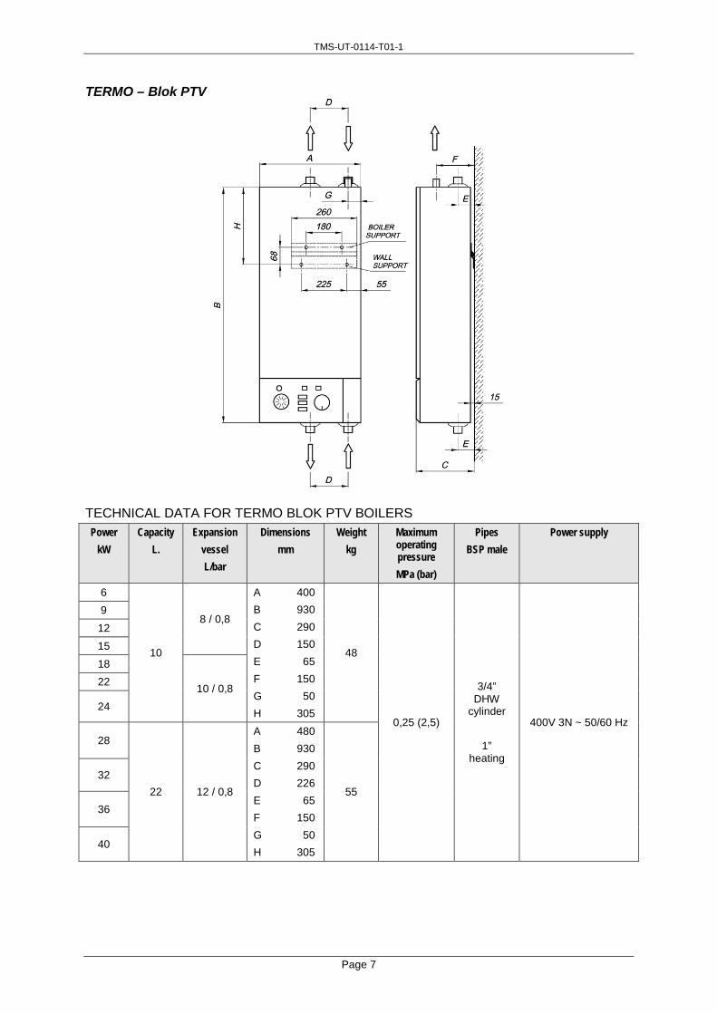
TERMO – Blok PTV
TECHNICAL DATA FOR TERMO BLOK PTV BOILERS
Power kW
Capacity L.
Expansion vessel L/bar
Dimensions mm
Weight kg
Maximum operating pressure MPa (bar)
Pipes BSP male
Power supply
6
10
8 / 0,8
A 400 B 930 C 290 D 150 E 65 F 150 G 50 H 305
48
0,25 (2,5)
3/4” DHW
cylinder
1” heating
400V 3N ~ 50/60 Hz
9 12 15 18
10 / 0,8 22
24
28
22 12 / 0,8
A 480 B 930 C 290 D 226 E 65 F 150 G 50 H 305
55 32
36
40
Page 7

TMS-UT-0114-T01-1
TERMO - Extra
TECHNICAL DATA FOR TERMO EXTRA BOILERS Power
kW Capacity
Lit. Dimensions
mm Weight
kg Maximum operating pressure MPa (bar)
Pipes BSP male
Power supply
6
6
A 330 B 750 C 230 D 100 E 57 F 126
26
0,25 (2,5)
3/4”
400V 3N ~ 50/60 Hz
9
12
14
16
18
10
A 400 B 750 C 230 D 150 E 57 F 126
32 1” 22
24
28
19
A 400 B 930 C 310 D 162 E 115 F 109
45 6/4”
32
36
40
44
48
Page 8

TMS-UT-0114-T01-1
TECHNICAL DATA FOR TERMO EXTRA BOILERS Power
kW Capacity
Lit. Dimensions
mm Weight
kg Maximum operating pressure MPa (bar)
Pipes BSP male
Power supply
52
19
A 400 B 930 C 310 D 162 E 115 F 109
45
0,25 (2,5)
6/4”
400V 3N ~ 50/60 Hz
56
60
64
32
A 550 B 930 C 310 D 316 E 115 F 175
72 2” 72 80 88 96
Page 9

TMS-UT-0114-T01-1
2.2 Expansion Vessel Characteristics (Termo Blok and Termo Blok TV Boilers)
Volume of Expansion
Vessel
L
Maximum Expansion
Vessel Pressure
MPa (bar)
Filling Pressure
MPa (bar)
Maximum Pressure
In the Heating System
MPa (bar)
Height Of the Central Heating System
m
Effective Capacity
Of Expansion
Vessel
L
Adsorption Capacity
%
Maximum Amount of Water in
the System
L
Maximum Power of
Boiler
kW
6
0.4 (4) 0.08 (0.8) 0.3 (3) 10
3.0
50%
86 12 8 4.0 114 16
10 5.0 143 20 12 6.0 172 25
Values are related to working temperature range from 10°C to 90°C.
2.3. Power supply characteristics 230V/400V POWER Nominal
current Fuse current Rated short-
circuit breaking capacity
Icn (EN 60898)
Rated short-circuit
breaking capacity
Icn (IEC 947-2)
Min. conductor's
cross-section
Fuse type RCCB switch type
400V 3N ~ 50/60 Hz 6 kW 8,70 A 10 A
10 kA 15 kA
5 x 2,5 mm2 B10-3
25 / 0,03 A
9 kW 13,04 A 16 A B16-3
12 kW 17,39 A 25 A
5 x 4 mm2 B25-3
14 kW 20,29 A
16 kW 23,19 A 32 A B32-3
18 kW 26,09 A
5 x 6 mm2 40 / 0,03 A
20 kW 28,99 A
40 A B40-3 22 kW 31,88 A
24 kW 34,78 A
5 x 10 mm2 28 kW 40,58 A 50 A B50-3 63 / 0,03 A
(0,3A Termo Extra)
32 kW 46,38 A
63 A B63-3 36 kW 52,17 A 5 x 16 mm2
40 kW 57,97 A
44 kW 63,77 A 80 A
50 kA 105 kA
5 x 25 mm2
NH 160 A 0,3A
48 kW 69,57 A
52 kW 75,36 A
100 A 56 kW 81,16 A
5 x 35 mm2 60 kW 86,96 A
64 kW 92,75 A 125 A
72 kW 104,35 A 5 x 50 mm2
80 kW 115,94 A
160 A 88 kW 127,54 A 5 x 70 mm2
96 kW 139,13 A
230V N ~ 50/60 Hz 6 kW 26,1 A 32 A 10 kA 15 kA 3 x 6 mm2 B32 40 / 0,03 A
9 kW 39,2 A 50 A 10 kA 15 kA 3 x 10 mm2 B50 63 / 0,03 A min. conductor's cross-section in mm2 is based on maximum length of 20 m.
Page 10
TMS-UT-0114-T01-1
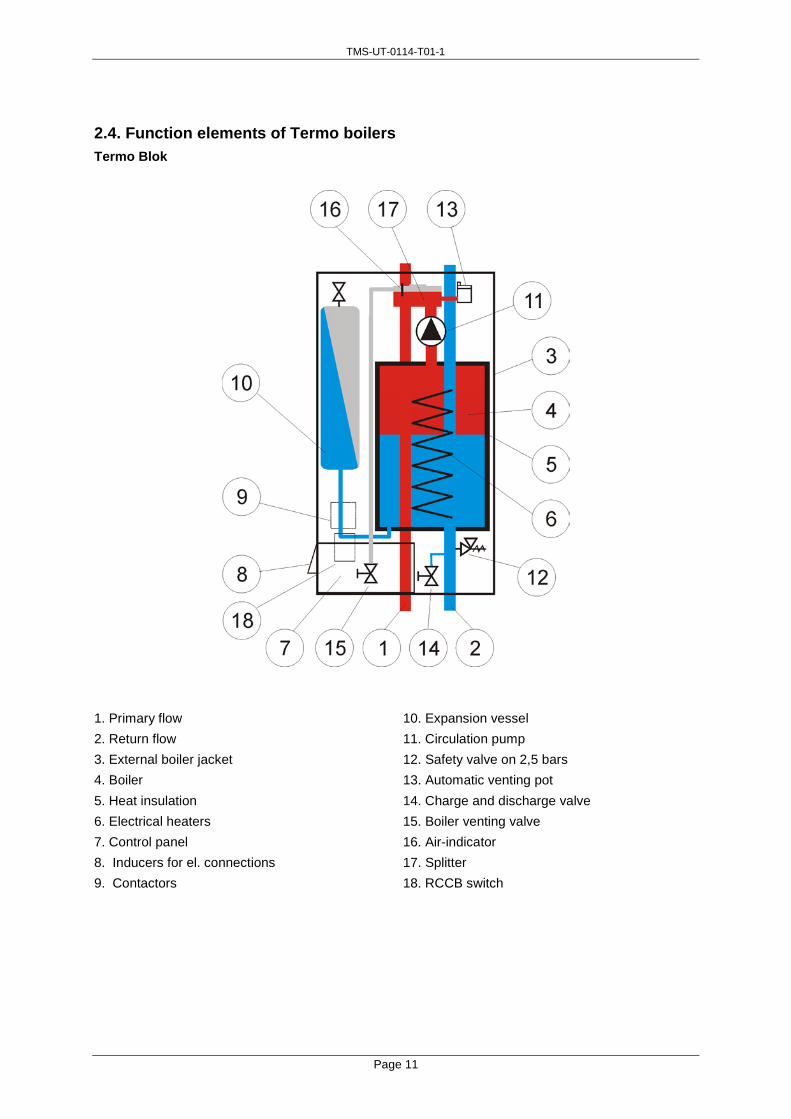
2.4. Function elements of Termo boilers Termo Blok
1. Primary flow 10. Expansion vessel 2. Return flow 11. Circulation pump 3. External boiler jacket 12. Safety valve on 2,5 bars 4. Boiler 13. Automatic venting pot 5. Heat insulation 14. Charge and discharge valve 6. Electrical heaters 15. Boiler venting valve 7. Control panel 16. Air-indicator 8. Inducers for el. connections 17. Splitter 9. Contactors 18. RCCB switch
Page 11

TMS-UT-0114-T01-1
Termo Blok PTV
1. Primary flow 11. Circulation pump 2. Return flow 12. Safety valve on 2,5 bars 3. External boiler jacket 13. Automatic venting valve 4. Boiler 14. Charge and discharge valve 5. Heat insulation 15. Manual venting valve 6. Electrical heaters 16. Air-indicator 7. Control panel 17. Splitter 8. Inducers for el. connections 18. RCCB switch 9. Contactors 19. Pump for domestic water cylinder 10. Expansion vessel 20. Primary flow for domestic water cylinder
Page 12

TMS-UT-0114-T01-1
TERMO-Extra
1. Primary flow 6. Electrical heaters 2. Return flow 7. Control panel 3. External boiler jacket 8. Inducers for el. Connections 4. Boiler 9. Contactors 5. Heat insulation 10. Charge and discharge valve
Page 13
TMS-UT-0114-T01-1
3.0 General requirements
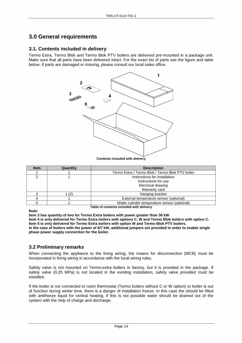
3.1. Contents included in delivery Termo Extra, Termo Blok and Termo Blok PTV boilers are delivered pre-mounted in a package unit. Make sure that all parts have been delivered intact. For the exact list of parts see the figure and table below. If parts are damaged or missing, please consult our local sales office.
Contents included with delivery
Item Quantity Description
1 1 Termo Extra / Termo Blok / Termo Blok PTV boiler 2 1 Instructions for installation
Instructions for use Electrical drawing
Warranty card 3 1 (2) Hanging bracket 4 1 External temperature sensor (optional) 5 1 Water cylinder temperature sensor (optional)
Table of contents included with delivery Note: Item 3 has quantity of two for Termo Extra boilers with power greater than 36 kW Item 4 is only delivered for Termo Extra boilers with options C, W and Termo Blok boilers with option C. Item 5 is only delivered for Termo Extra boilers with option W and Termo Blok PTV boilers. In the case of boilers with the power of 6/7 kW, additional jumpers are provided in order to enable single phase power supply connection for the boiler.
3.2 Preliminary remarks When connecting the appliance to the fixing wiring, the means for disconnection (MCB) must be incorporated in fixing wiring in accordance with the local wiring rules. Safety valve is not mounted on Termo-extra boilers in factory, but it is provided in the package. If safety valve (0,25 MPa) is not located in the existing installation, safety valve provided must be installed. If the boiler is not connected to room thermostat (Termo boilers without C or W option) or boiler is out of function during winter time, there is a danger of installation freeze. In this case the should be filled with antifreeze liquid for central heating, if this is not possible water should be drained out of the system with the help of charge and discharge.
Page 14

TMS-UT-0114-T01-1
Recommended pressure of central heating installation is 0,15 mpa (1,5 bar), maximum pressure is 0,25 mpa (2,5 bar).
3.3. Recommendations for various installation types Following flow chart is provided in order to help installers choosing the right type of boiler for desired installation type. At the end of each tree is the number of corresponding appendix. Each appendix consists of the following: the hydraulic drawing, a typical electrical drawing, the description of connection plate, the description of control panel, and the description of the complete central heating system.
Central heatingtype
Control panel
Central heatingand hot water
Central heating
Instalationtype
Electroniccontrol panel
Basiccontrol panel
Termo-Blok PTV-eAppendix - 1
orTermo-Extra-eAppendix - 2
Termo-Extra-eAppendix - 2
New installation Existing installation
Instalationtype
Termo-BlokPTV-mAppendix - 3
orTermo-Extra-m
Appendix - 4
Termo-Extra-mAppendix - 4
New installation Existing installation
Control panel
Instalationtype
Electroniccontrol panel
Basiccontrol panel
Termo-Blok-eAppendix - 5
orTermo-Extra-eAppendix - 6
Termo-Extra-eAppendix - 6
New installation Existing installation
Instalationtype
Termo-Blok-mAppendix - 7
orTermo-Extra -m
Appendix - 8
Termo-Extra-mAppendix - 8
New installation Existing installation
Note: These installation samples should not be used as the detailed installation plan. Before installation observe the local regulations.
3.4. Installation site 3.4.1. Position of a boiler The location must provide adequate space for servicing and air circulation around the boiler. The boiler may be installed in any room, although particular attention is drawn to the local regulations in respect to the installation of a boiler in a room containing a bath or a shower. The boiler must be mounted on a flat, vertical wall, which must be sufficiently robust to bear the weight of the boiler. The
Page 15

TMS-UT-0114-T01-1
boiler may be installed on a combustible wall, subject to the requirements of the Local Authorities and Building Regulations. Following figure shows the recommended minimal distances.
Minimal distances
It is possible to reduce recommended minimal distances, but the following requirements must be met: Power supply connection, located at the left bottom side of boilers must be accessible Bottom part of boiler must be accessible to allow change of heater Control panel on bottom side of boiler must be accessible Basic air circulation must be maintained
3.4.2. Power supply The boiler is rated as a high power appliance and fixed wiring must be used. Please observe chapters 2.2. and 2.3. about fuse and conductor requirements. When connecting the appliance to the fixing wiring the means for disconnection (MCB) must be incorporated in fixing wiring in accordance with the local wiring rules. RCCB (RCD) switch 0,03A sensitivity is fitted inside a boiler. Note: In some cases additional measures must be taken, subject to the requirements of the Local Authorities. 3.5. System requirements 3.5.1. Pipe work Pipe work that is not a forming part of the useful heating surface should be insulated to help prevent heat loss and possible freezing, particularly where pipes are run through roof spaces and ventilated under floor spaces. Draining taps must be located in accessible positions, which permit the draining of the whole system including the boiler and the hot water system. All capillary joints in all DHW pipe work must be made with lead free solder. 3.5.2. Cleansing and flushing the system Flushing of system is highly recommended, this will prevent damage to the appliance made by dirt from the system. Particularly where a new boiler is to be fitted to an existing system, it is a good practice that the system is thoroughly cleansed. To prevent the formation of deposits and to prevent serious damage to the appliance and system, cleansers must be used carefully and must be completely removed by thoroughly flushing the system. Cleansers should only be left in systems for the maximum of 24 hours.
Page 16

TMS-UT-0114-T01-1
3.5.3. Filling and preparing heating system The system can be filled using the built-in filling valve or via a separate filling point fitted at a convenient position on the heating circuit. The connection must be removed when filling is completed. Where local Water Authority regulation does not allow temporary connection, a sealed system filler pump with break tank must be used. The heating system will not be filled automatically from the domestic hot water side. Note: For the heating system to operate properly the indicator of manometer must be between 1,2 and 1,5 bar when system is cold. It is very important to use soft water or fluids for central heating. Do not fill the system with water from private source. 3.5.4. Pressure relief valve A pressure relief valve is provided with the boiler. This safety device is required on all sealed C.H. systems and is preset at 2,5 bar and provided with a 15 mm compression connection for a discharge pipe, which must be of no less than 15 mm in diameter. The pressure relief valve must not be used for draining purposes. 3.5.5. Pressure gauge This is factory fitted to the Termo Blok and Termo Blok PTV boiler and indicates the primary circuit pressure to facilitate filling and testing. In the case of Termo Extra boiler pressure gauge must be fitted to the installation. 3.5.6. Expansion vessel Termo Blok and Termo Blok PTV boilers incorporate an expansion vessel. Refer to chapter 2.1 for more information about incorporated expansion vessel. Expansion vessel is not incorporated within Termo Extra boilers and it must be fitted in the system. If the nominal capacity of the built in expansion vessel is not sufficient for the heating system (for instance in the case of modernization of old open systems) an additional expansion vessel can be installed externally to the boiler. It should be fitted in the return pipe as close as possible to the boiler. 3.5.7. Circulating pump The circulation pump is included in Termo Blok and Termo Blok PTV boilers. For Termo Extra boilers pump is not incorporated within the boiler and it must be mounted separately. The following figure represents pump characteristics. 3.5.8. Venting The boiler is fitted with an automatic and manual air vent. Additionally boiler is fitted with the air detector that will stop boiler in the case of air presence.
Page 17

TMS-UT-0114-T01-1
4. Boiler installation sequence
4.1. Transporting the appliance Important: The following lift operation exceeds the recommended weight for a one-man lift. General recommendations when handling Clear the route before attempting the lift. Safe lifting techniques are used – keep back straight – bend using legs. Keep load as close to body as possible. Do not twist – reposition your feet. If 2 persons are performing the lift, ensure coordinated movements during lift. Avoid upper body/top heavy bending - do not lean forward/sideways. It is recommended to wear suitable cut resistant gloves with good grip to protect against sharp edges and ensure good grip. Always use assistance if required. Positioning of Appliance for Final Installation Fit bracket securely onto wall before lifting appliance into position. Ensure that stable balance is achieved and lift upwards to drop into place onto bracket. Ensure coordinated movements during a two-person lift to ensure equal spread of weight of load It is recommended to wear suitable cut resistant gloves with good grip to protect against sharp edges and ensure good grip when handling appliance.
4.2. Select position for boiler Refer to chapter 3.4.1. for information regarding the appliance position. In general, the boiler must be positioned in such manner that:
There is enough space around the boiler for service and maintenance There is no chance for boiler to be submerged into water There is no chance for boiler to be poured with significant amount of water Normal level of air circulation can be maintained All necessary pipe work can be connected
4.3. Fitting the boiler hanging bracket Fix the hanging bracket (2) to the wall (1) using the plugs and M8 or M10 screws. Lift up boiler (3) above hanging bracket (2), gently lean it to the wall (1) and slide it down to the hanging bracket (2).
Wall mounting
Note: If the boiler is to be fitted in a timber framed building ensure that the bracket is secured to a substantial part of the timber frame capable of bearing the weight of the boiler.
Page 18

TMS-UT-0114-T01-1
4.4. Removing/fixing the front and top case
Grasp the front case by its sides, pull it towards the front and remove it by lifting it of the unit, push top cover towards back and lift it of the unit.
4.5. Pipe work connection Note: Observe chapter 3.5. for the system requirements before proceeding. System flushing is necessary in order to prevent damage to appliance. It is recommended to fit valves on flow and return pipe work in order to enable easy disconnection/separation of boiler from the central heating system. The following figure indicates flow and return for the central heating on Termo Extra, Termo Blok and Termo Blok PTV boilers.
TERMO-Extra
TERMO-Blok, Termo Blok PTV
Flow and return on Termo Extra, Termo Blok and Termo Blok PTV boilers
Page 19
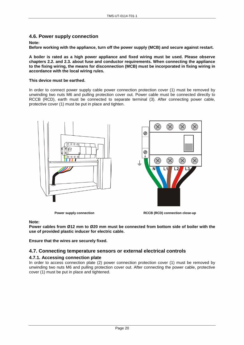
TMS-UT-0114-T01-1
4.6. Power supply connection Note: Before working with the appliance, turn off the power supply (MCB) and secure against restart. A boiler is rated as a high power appliance and fixed wiring must be used. Please observe chapters 2.2. and 2.3. about fuse and conductor requirements. When connecting the appliance to the fixing wiring, the means for disconnection (MCB) must be incorporated in fixing wiring in accordance with the local wiring rules. This device must be earthed. In order to connect power supply cable power connection protection cover (1) must be removed by unwinding two nuts M6 and pulling protection cover out. Power cable must be connected directly to RCCB (RCD), earth must be connected to separate terminal (3). After connecting power cable, protective cover (1) must be put in place and tighten.
Power supply connection RCCB (RCD) connection close-up
Note: Power cables from Ø12 mm to Ø20 mm must be connected from bottom side of boiler with the use of provided plastic inducer for electric cable. Ensure that the wires are securely fixed.
4.7. Connecting temperature sensors or external electrical controls 4.7.1. Accessing connection plate In order to access connection plate (2) power connection protection cover (1) must be removed by unwinding two nuts M6 and pulling protection cover out. After connecting the power cable, protective cover (1) must be put in place and tightened.
Page 20

TMS-UT-0114-T01-1
Accessing connection plate
4.7.2. Connecting external temperature sensor This is applicable only to Termo Extra boilers with option C or W, Termo Blok boilers with option C and Termo Blok PTV boilers. External temperature sensor (delivered with boiler) must be fitted in such manner that it is not affected by sudden temperature changes (exposure to direct sunlight). When fitting sensor please observe the arrow marking top position (it can be seen when protective cover is removed). Connector for outdoor temperature sensor has factory mounted resistor for testing boiler at -13ºC. After installation and initial testing, resistor must be removed and wires from external temperature sensor must be connected.
protective cover
base
External temperature sensor External temperature sensor connection point
on boiler's connection plate
Note: For connecting external temperature sensor two-wire cable can be used, of diameter from 0.6mm2 to 1.5 mm2. 4.7.3. Connecting domestic hot water temperature sensor This is applicable only to Termo Extra boilers with option C and Termo Blok PTV boilers. Domestic hot water temperature sensor (delivered with the boiler) must be fitted in such manner that reading of correct cylinder temperature is ensured. Water cylinder usually has a spot provided for inserting temperature sensor. If this is not the case temperature sensor must have contact with metal part of the cylinder (under the insulation).
Page 21
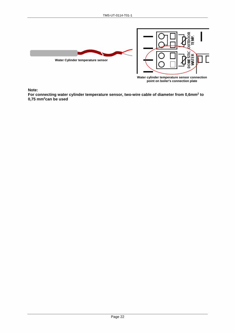
TMS-UT-0114-T01-1
Water Cylinder temperature sensor
Water cylinder temperature sensor connection
point on boiler's connection plate Note: For connecting water cylinder temperature sensor, two-wire cable of diameter from 0,6mm2 to 0,75 mm2can be used
Page 22
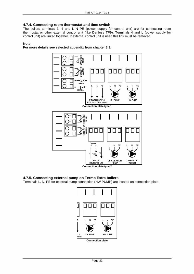
TMS-UT-0114-T01-1
4.7.4. Connecting room thermostat and time switch The boilers terminals 3, 4 and L N PE (power supply for control unit) are for connecting room thermostat or other external control unit (like Danfoss TP9). Terminals 4 and L (power supply for control unit) are linked together. If external control unit is used this link must be removed. Note: For more details see selected appendix from chapter 3.3.
Connection plate type 1
Connection plate type 2
4.7.5. Connecting external pump on Termo Extra boilers Terminals L, N, PE for external pump connection (HW PUMP) are located on connection plate.
Connection plate
Page 23
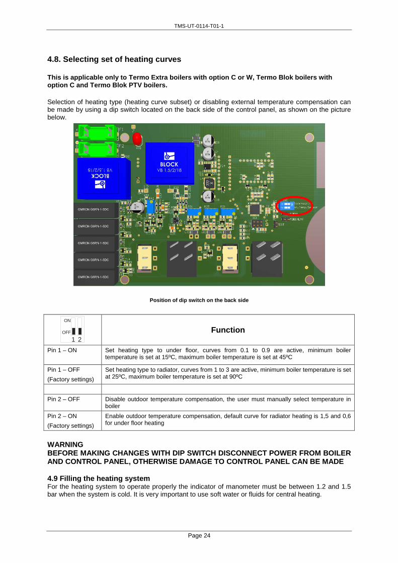
TMS-UT-0114-T01-1
4.8. Selecting set of heating curves This is applicable only to Termo Extra boilers with option C or W, Termo Blok boilers with option C and Termo Blok PTV boilers. Selection of heating type (heating curve subset) or disabling external temperature compensation can be made by using a dip switch located on the back side of the control panel, as shown on the picture below.
Position of dip switch on the back side
1 2
ON
OFF
Function
Pin 1 – ON
Set heating type to under floor, curves from 0.1 to 0.9 are active, minimum boiler temperature is set at 15ºC, maximum boiler temperature is set at 45ºC
Pin 1 – OFF (Factory settings)
Set heating type to radiator, curves from 1 to 3 are active, minimum boiler temperature is set at 25ºC, maximum boiler temperature is set at 90ºC
Pin 2 – OFF Disable outdoor temperature compensation, the user must manually select temperature in
boiler Pin 2 – ON (Factory settings)
Enable outdoor temperature compensation, default curve for radiator heating is 1,5 and 0,6 for under floor heating
WARNING BEFORE MAKING CHANGES WITH DIP SWITCH DISCONNECT POWER FROM BOILER AND CONTROL PANEL, OTHERWISE DAMAGE TO CONTROL PANEL CAN BE MADE 4.9 Filling the heating system For the heating system to operate properly the indicator of manometer must be between 1.2 and 1.5 bar when the system is cold. It is very important to use soft water or fluids for central heating.
Page 24

TMS-UT-0114-T01-1
5. Commissioning
5.1. Central heating system check Check for pressure in the system, it should be from 1.2 to 1.5 bar when the system is cold. Vent all heating elements and installation.
5.2. Preliminary electrical check For single phase system: Check if power cable is tightened on RCCB (RCD) terminals Check the presence of phase on RCCB (RCD) input terminals inside boiler Measure exact voltage between L and N lines, if it is10% higher than nominal voltage
on the appliance, the appliance itself can be damaged. For three phase system: Check if power cable is tightened on RCCB (RCD) terminals Check the presence of each phase on RCCB (RCD) input terminals inside boiler Measure exact voltage between L1 – L2, L1 – L3, L2 – L3, L1 –N. If there is no
voltage between any combinations of phases one phase is missing and the heating elements inside the appliance can be damaged. If the voltage between phases is 10% higher than nominal voltage of the appliance, the appliance itself can be damaged
For all systems: Check if fixed wiring system is used and that MCB is installed, and conform to chapter
2.2. or 2.3. Check if the used power cable conforms to chapter 2.2 or 2.3 Test the RCCB (RCD) switch by pressing T button on it Test the overheating system as described in appendix 9
5.3. Changing the speed of pump for central heating For Termo Blok and Termo Blok PTV: open the cover of boiler as described in chapter 4.4. and locate the central heating pump; use chapter 2.4. for assistance. Move speed slider (1) to desired mark. For Termo Extra boilers an external pump is fitted, so consult the pump manuals for guidance.
Selecting pump speed
Page 25

TMS-UT-0114-T01-1
5.4. Working with standard control panel
Standard electromechanical control panel
An automatic consists of the following elements: 1 – Indicator of temperature /pressure in boiler 2 – Working thermostat 3 – Switch for the 2nd and 3rd operation stage 4 – Cutout thermostat with manual deactivation (switches off at ca 100 oC) 5 – Indicator of air appearance in the boiler - air-indicator 6 - Switch for ON/OFF and 1st heating stage 7 – Fuse 2,5A protecting the pump and the switches 8 – Indication of heater operation 9 - Indicates low voltage protection - under 180V Putting on the central heating By switching the switch (6) ON, the central heating system is switched on and the first power stage is active. With switch (3) it is possible to control manually the second or third power stage of the boiler. Boilers with 3 stages have soft start for the second and third stage, and switches (3) have only limiting function. If the boiler is heating, heaters in operation (8) light is on; if heaters are not working and the boiler is in standby, only ON/OFF light is on. Adjustment of desired temperature of central heating With the help of working thermostat (2) it is possible to select a fixed desired temperature in boiler. Working thermostat range from 20ºC to 90ºC. Recommended temperature is about 60ºC (12 clock position). Air in the boiler (5), red light If the air appears in the boiler, the signalization of air in the boiler turns on (5) and the boiler operation stops. In this way the boiler is protected against burning through due to the appearance of air. For continuation of operation, the boiler should be vented. If the boiler is correctly vented, the operation of boiler continues automatically. Voltage drop (9), red light If the voltage in the network line drops below 180V by phase, the signalization of under voltage protection (9) turns on, the boiler automatically switches off in order to protect electronics and contactors inside the boiler. The boiler will automatically continue the operation when the network voltage reaches values above 180V. Cutout thermostat - turning on Cutout thermostat (safety thermostat) (4) protects the boiler against rapid increase of temperature above 115°C. The fuse turns the boiler off and ejects the RCCB (RCD)-switch. For the boiler to continue working it is necessary to take off the protection cover from the cutout thermostat and press the red key, upon which the RCCB (RCD)-switch should be switched on again.
Page 26

TMS-UT-0114-T01-1
NOTE: If the room thermostat is on, check if it is set at the necessary room temperature and if supply batteries are in order, otherwise the boiler will not operate.
5.5. Working with electronic control panels (option E)
Part number: 1659
4 0
2bar
52
12
11
1 2 3
4
5
6
0
I
7
Electronic control panel without external temperature compensation
1. Multipurpose – temperature indicator (temperature of boiler,
adjustment of temperature)
2. Indication of operation degree of heaters (1., 2., 3.....7)
3. Signalization of air appearance in the boiler (red light)
4. Signalization of under voltage protection (red light)
5. Signalization of boiler operation (green light)
6. Adjustment of temperature in boiler
7. Switch for central heating switching on and off
8. Thermal fuse
Putting on central heating By switching the switch (7) to the position 1, the central heating system is switched on. Upon switching on, a desired water temperature in boiler is displayed for 5 seconds, signalization of boiler operation is twinkling (5). Upon 5 seconds real temperature in the boiler is displayed (1); if the current temperature in boiler meets the desired one, the signalization lamp of boiler operation (5) is switched off. Adjustment of desired temperature of central heating By pressing the key for temperature adjustment (6) the desired temperature in the boiler appears, the signalization lamp of boiler operation (5) is twinkling. By repeated pressing upwards or downwards it is possible to increase or decrease the desired sanitary water temperature. When the temperature is adjusted it is sufficient to wait for 5 seconds (signalization lamp of boiler operation (5) does not twinkle) in order for the boiler to memorizes a new temperature. Air in the boiler (3), red light If the air appears in the boiler, the signalization of air in the boiler turns on (3) and the boiler operation stops. In this way the boiler is protected against malfunction caused by the appearance of air. For the continuation of operation, the boiler should be vented. If the boiler is correctly vented, the operation of boiler continues automatically. Voltage drop (4), red light If the voltage in the network line drops below 180V by phase, the signalization of under voltage protection (4) turns on, the boiler automatically switches off in order to protect the electronics and
Page 27

TMS-UT-0114-T01-1
contactors inside the boiler. The boiler will automatically continue the operation when the network voltage reaches values above 180V. Cutout thermostat - turning on Cutout thermostat (safety thermostat) (8) protects the boiler against rapid increase of temperature above 115°C. The fuse turns the boiler off and ejects the RCCB (RCD)-switch. For the continuation of operation it is necessary to take off the protection cover from the cutout thermostat and press the red key, upon which the RCCB (RCD)-switch should be switched on again.
5.6. Working with electronic control panels (option C and W and Termo Blok PTV)
5.6.1. General Regardless of the selected regulation curve the maximum water temperature in the boiler is limited to 90°C for radiator heating and 50°C for floor heating. Factory setting of the curve is 1,5 for radiator heating. Factory setting of the curve is 0,6 for underfloor heating. Refer to chapter 1.4. for detailed description of heating curves. Refer to chapter 1.5. for detailed description of DHW functions. Refer to chapter 1.6. for detailed description of frost protection. Refer to chapter 4.8 for detailed description of selecting a desired set of heating curves.
Part number: 1659
4 0
2bar
52
12
11
1 2 3
4
5
6
0
I
7
Type 1 – Outdoor temperature compensation
Page 28

TMS-UT-0114-T01-1
Type 2 – Outdoor temperature compensation and sanitary water on Termo Extra or Termo Blok PTV
1. Display temperature reading from KTY probes from – 19°C (below -19°C the display shows --) up to +99°C (above +99°C
display is blinking), display of the desired temperature or curve during setup. Following warnings can be displayed: PF – power line voltage too low or air in the boiler P1 – frost protection for sanitary water is active P2 – frost protection for central heating is active o1 or c1 – thermal sensor for boiler temperature is not connected or it is short-circuited o2 or c2 – thermal sensor for external temperature is not connected or it is short-circuited o3 or c3 – thermal sensor for DHW temperature is not connected or it is short-circuited when heating function is turned off, every 24 hours controller will activate circulation pump for period of 10 seconds, in
order to prevent pump bearings corrosion. That will be indicated on the display as a "running light"
12. Safety thermostat
2. Led diodes of heaters stages The number of lighted diodes corresponds to the number of currently active heater stages (up to seven)
3. Led diode OK/air in boiler If there is no air in the boiler, the diode lights green. If the air appears in the boiler, the diode lights red and at the same time the operation of the device is stopped. After venting, the diode automatically changes the color to green and the operation of the boiler is continued.
4. Led diode too low supply voltage If the net voltage falls below 170 V red light appears and at the same time the operation of the device is stopped.
5. Led diode indication for central heating Indicates that the pump of central heating is active
6. Push button for adjustment of heating characteristics 7. Switch – heating on/off 8. Push-button for adjusting characteristics of sanitary water conditioning 9. Sanitary water conditioning on/off 10. Led diode indication for sanitary water conditioning,
It indicates the circulation pump operation for sanitary warm water conditioning. 11. Indicator of water pressure in heating system.
Page 29
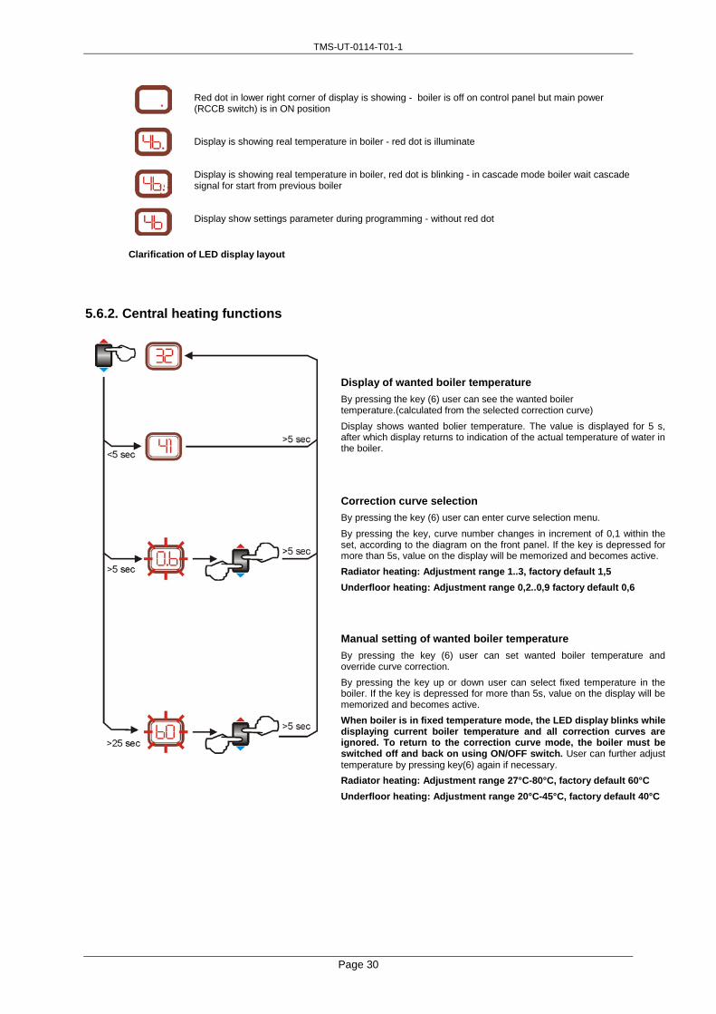
TMS-UT-0114-T01-1
Red dot in lower right corner of display is showing - boiler is off on control panel but main power (RCCB switch) is in ON position
Display is showing real temperature in boiler - red dot is illuminate
Display is showing real temperature in boiler, red dot is blinking - in cascade mode boiler wait cascade signal for start from previous boiler
Display show settings parameter during programming - without red dot
Clarification of LED display layout
5.6.2. Central heating functions
Display of wanted boiler temperature By pressing the key (6) user can see the wanted boiler temperature.(calculated from the selected correction curve) Display shows wanted bolier temperature. The value is displayed for 5 s, after which display returns to indication of the actual temperature of water in the boiler.
Correction curve selection By pressing the key (6) user can enter curve selection menu. By pressing the key, curve number changes in increment of 0,1 within the set, according to the diagram on the front panel. If the key is depressed for more than 5s, value on the display will be memorized and becomes active. Radiator heating: Adjustment range 1..3, factory default 1,5 Underfloor heating: Adjustment range 0,2..0,9 factory default 0,6
Manual setting of wanted boiler temperature By pressing the key (6) user can set wanted boiler temperature and override curve correction. By pressing the key up or down user can select fixed temperature in the boiler. If the key is depressed for more than 5s, value on the display will be memorized and becomes active. When boiler is in fixed temperature mode, the LED display blinks while displaying current boiler temperature and all correction curves are ignored. To return to the correction curve mode, the boiler must be switched off and back on using ON/OFF switch. User can further adjust temperature by pressing key(6) again if necessary. Radiator heating: Adjustment range 27°C-80°C, factory default 60°C Underfloor heating: Adjustment range 20°C-45°C, factory default 40°C
Page 30
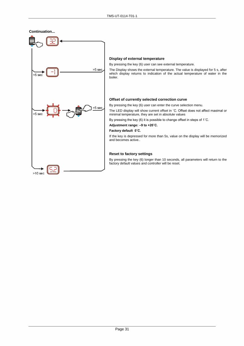
TMS-UT-0114-T01-1
Continuation...
Display of external temperature By pressing the key (6) user can see external temperature. The Display shows the external temperature. The value is displayed for 5 s, after which display returns to indication of the actual temperature of water in the boiler.
Offset of currently selected correction curve By pressing the key (6) user can enter the curve selection menu. The LED display will show current offset in ˚C. Offset does not affect maximal or minimal temperature, they are set in absolute values By pressing the key (6) it is possible to change offset in steps of 1˚C. Adjustment range: –9 to +20˚C. Factory default 0˚C. If the key is depressed for more than 5s, value on the display will be memorized and becomes active..
Reset to factory settings By pressing the key (6) longer than 10 seconds, all parameters will return to the factory default values and controller will be reset.
Page 31

TMS-UT-0114-T01-1
5.6.3. Domestic water functions (control panel type 2)
Display of desired temperature of domestic water If the key is held pressed less than 5 s the LED display will show the desired temperature in domestic water storage. The value is displayed for 5 seconds, after which the display normally shows the real temperature of water in the boiler.
Setting the desired temperature in domestic water storage By pressing the key (8) user can enter the domestic water temperature menu. The desired water temperature in domestic water storage is blinking. By pressing the key (8) the value of desired domestic water temperature in domestic water storage is changing in steps of 1°C. If the key is held pressed less than 5 s the value from the display becomes the desired domestic water temperature. Possible adjustment is from 10°C up to 65°C. Factory adjustment is 50°C.
Displaying software version and factory reset By pressing the key (8) longer than 15 s, the LED will show the software version and the factory reset of central heating parameters will occur.
Page 32
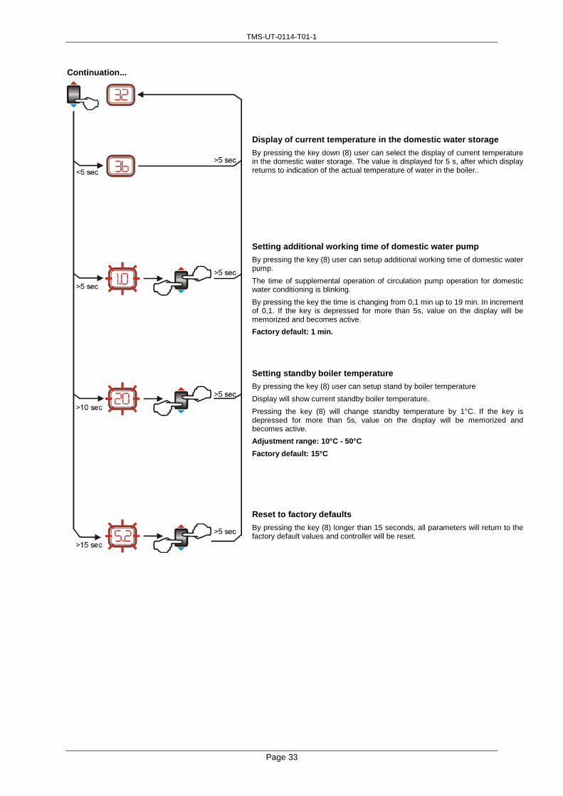
TMS-UT-0114-T01-1
Continuation...
Display of current temperature in the domestic water storage By pressing the key down (8) user can select the display of current temperature in the domestic water storage. The value is displayed for 5 s, after which display returns to indication of the actual temperature of water in the boiler..
Setting additional working time of domestic water pump By pressing the key (8) user can setup additional working time of domestic water pump. The time of supplemental operation of circulation pump operation for domestic water conditioning is blinking. By pressing the key the time is changing from 0,1 min up to 19 min. In increment of 0,1. If the key is depressed for more than 5s, value on the display will be memorized and becomes active. Factory default: 1 min.
Setting standby boiler temperature By pressing the key (8) user can setup stand by boiler temperature Display will show current standby boiler temperature. Pressing the key (8) will change standby temperature by 1°C. If the key is depressed for more than 5s, value on the display will be memorized and becomes active. Adjustment range: 10°C - 50°C Factory default: 15°C
Reset to factory defaults By pressing the key (8) longer than 15 seconds, all parameters will return to the factory default values and controller will be reset.
Page 33

TMS-UT-0114-T01-1
5.6.4. Central heating functions with heating curves disabled
Display of desired temperature in the boiler If the key (6) is held pressed less than 5 s the LED display will show the desired temperature in the boiler. The value is displayed for 5 seconds, after which the display normally shows the real temperature of water in the boiler.
Setting the desired temperature in the boiler By pressing the key (6) user can enter the boiler temperature menu. The desired boiler temperature is blinking. By pressing the key (6) UP or DOWN, the desired boiler temperature can be set in steps of 1°C. If the key is held pressed less than 5 s the value from the display becomes the desired boiler temperature. Possible adjustment is from 20°C up to 90°C for radiator heating. Possible adjustment is from 15°C up to 45°C for under floor heating.
Reset to factory defaults By pressing the key (6) longer than 15 seconds, all parameters will return to the factory default values and controller will be reset.
Page 34

TMS-UT-0114-T01-1
5.6.4.1 Access to special service menu
Access to special service menu To access in special service menu press simultaneously key (6) during switching ON main switch on boiler - RCCB (in that moment key (7) must be turned off)
Limiting maximum boiler temperature
By pressing the key (6) user can limit maximum boiler temperature. Factory defined maximum temperature starts to blink. By pressing up or down user can set new maximum temperature. If the key is depressed for more than 5s, value on the display will be memorized and becomes active. Radiator heating: Adjustment range 60°C-90°C, factory default 80°C Underfloor heating: Adjustment range 30°C-50°C, factory default 45°C
Setting the minimal boiler temperature By pressing the key (6) user can set minimal boiler temperature. Minimal boiler temperature starts blinking. By pressing the key user can select the desired minimal boiler temperature. Temperature changes in steps of 1°C. If the key is depressed for more than 5s, value on the display will be memorized and becomes active. Radiator heating: Adjustment range 20°C-45°C, factory default 45°C Underfloor heating: Adjustment range 15°C-30°C, factory default 30°C
Setting the central heating pump delay By pressing key (6) user can change pump delay time between 0 - 15 min. Factory settings is 0. Selecting the time delay between steps for power regulation By pressing the key (6) user can change the time delay between step for power regulation in the range from 5 to 60 seconds. Default value depends on the number of stages for power regulation – each stage will add 5 seconds. For example, 3 stages will have 3*5=15 seconds between successive stages turn-on, 7 stages will have 7*5=35 seconds between sucessive stages turn-on. Turn of delay is fixed to 1 second.
Selecting the number of steps for power regulation By pressing the key (6) servicer can change the number of steps for power regulation. By pressing the key it is possible to select 2 to 7 steps for power regulation. Default settings: - boilers from 4,5 to 16 kW have only two power levels, boilers from 18 to 24 kW have three power levels and boilers from 28 up to 96 kW have seven power levels. Change in the number of stages will cause time delay parameter to be changed (see below) !
Page 35

TMS-UT-0114-T01-1
5.7. Starting the pump manually To start the pump it is necessary to turn off the protection plug on its front side (1), below which there is an axis with the groove for screwdriver. Using the screwdriver, the pump (2) should be turned several times in the direction of the arrow on the pump head and the boiler should be put on again.
When the pump starts the operation the temperature of water in the boiler and the temperature of sanitary water should be selected. The optimal temperature for central heating is between 60 and 70°C. If the room thermostat is connected to the boiler, the desired room temperature should be adjusted according to the instructions of the producer of the room thermostat.
6. Maintenance
6.1. Periodic checking We recommend the inspection of the device once a year by the authorized service provider (before heating season). This service is not included in the warranty. During the inspection all electric and water connections should be tightened, the system should be vented and – if necessary – filled up, valves and general functionality of the device should be checked. RCCD switch - pressing the TEST button must disconnect the RCCD switch. This testing procedure insures that switch is functioning properly. We recommend this test once or twice in heating season. Safety thermostat – we recommended to check safety thermostat before every heating season by heating up the sensor with heating fan or lighter over 100°C must actuate overheating protection by switching off the RCCD switch. Safety valve should be checked once a year (before the beginning of heating season) to ensure proper functioning and avoiding appearance of water calculus. If the boiler is not connected to the room thermostat or if the boiler is out of function during the winter time, there is a danger of installation freezing. In this case the system should be filled with antifreeze liquid for central heating, and if this is not possible water should be drained out.
6.2. Cleaning It is not permitted to use aggressive media (e.g. gasoline, kerosene or solvent) for cleaning the product. Media for cleaning plastics or dishwashing media can be used for the external shell and decorative cover. Control panel should be cleaned with dry or moist cloth (not wet).
Page 36
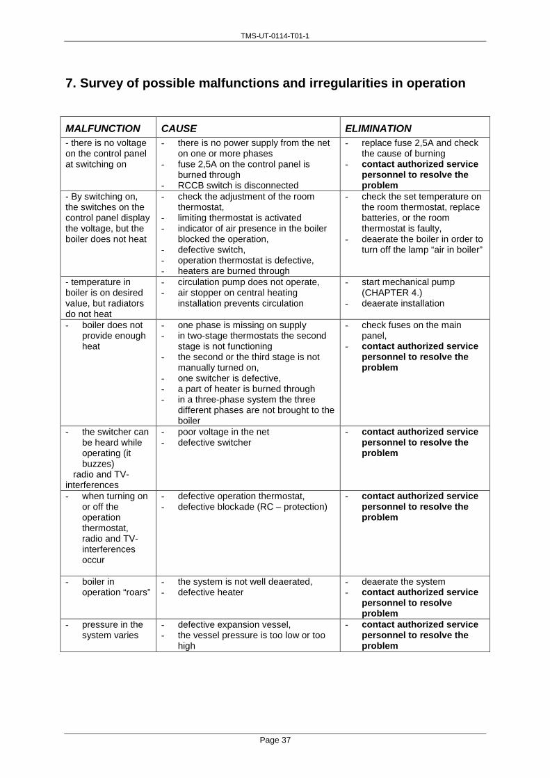
TMS-UT-0114-T01-1
7. Survey of possible malfunctions and irregularities in operation
MALFUNCTION CAUSE ELIMINATION - there is no voltage on the control panel at switching on
- there is no power supply from the net on one or more phases
- fuse 2,5A on the control panel is burned through
- RCCB switch is disconnected
- replace fuse 2,5A and check the cause of burning
- contact authorized service personnel to resolve the problem
- By switching on, the switches on the control panel display the voltage, but the boiler does not heat
- check the adjustment of the room thermostat,
- limiting thermostat is activated - indicator of air presence in the boiler
blocked the operation, - defective switch, - operation thermostat is defective, - heaters are burned through
- check the set temperature on the room thermostat, replace batteries, or the room thermostat is faulty,
- deaerate the boiler in order to turn off the lamp “air in boiler”
- temperature in boiler is on desired value, but radiators do not heat
- circulation pump does not operate, - air stopper on central heating
installation prevents circulation
- start mechanical pump (CHAPTER 4.)
- deaerate installation
- boiler does not provide enough heat
- one phase is missing on supply - in two-stage thermostats the second
stage is not functioning - the second or the third stage is not
manually turned on, - one switcher is defective, - a part of heater is burned through - in a three-phase system the three
different phases are not brought to the boiler
- check fuses on the main panel,
- contact authorized service personnel to resolve the problem
- the switcher can be heard while operating (it buzzes)
radio and TV-interferences
- poor voltage in the net - defective switcher
- contact authorized service personnel to resolve the problem
- when turning on or off the operation thermostat, radio and TV-interferences occur
- defective operation thermostat, - defective blockade (RC – protection)
- contact authorized service personnel to resolve the problem
- boiler in operation “roars”
- the system is not well deaerated, - defective heater
- deaerate the system - contact authorized service
personnel to resolve problem
- pressure in the system varies
- defective expansion vessel, - the vessel pressure is too low or too
high
- contact authorized service personnel to resolve the problem
Page 37

TMS-UT-0114-T01-1
- the actual temperature in the boiler is higher than the desired temperature and the safety thermostat is activated
- defective contactors - defective operation thermostat
- contact authorized service personnel to resolve the exact source of the problem
- RCCB switch disconnects
- defective heater, - humidity on conductors, - safety thermostat is activated
- check leakage, - contact authorized service
personnel to resolve the exact source of the problem
- RCCB switch cannot be reset
- safety thermostat is activated - pre-reset safety thermostat and then the RCCB switch
- contact authorized service personnel to resolve the exact source the of problem
Page 38

TMS-UT-0114-T01-1
Page 39

Termostroj
Croatia
APPENDIX - 1
Termo-Blok PTV
Contains: 1. Hydraulic sketch 3. Connection plate 2. Electric sketch 4. Control panel
1. Hydraulic sketch Termo-Blok PTV-e with room ‘stat (sample –1)
Basic characteristics: The sample of central heating system and DHW preparation that is set above is very popular. It is used in combination with DHW cylinder with indirect heating system. Electronic control panel uses the outside temperature information (with outside temperature probe) and automatically adjusts the temperature level in the boiler - radiators or under floor heating system. It is very simple to adjust the building or apartment insulations characteristics on the control panel. Sanitary water probe (supplied) must be installed into the water cylinder because the control panel needs information about domestic water temperature level. Domestic hot water has priority. Room ‘stat is recommended. Using the room ‘stat you can program several periods in a day with day temperature or reduced temperature level. In the standby position (only green led diode light) the boiler has antifreeze protection for central heating water and water in the cylinder.
Page 40

Termostroj
Croatia
APPENDIX - 1
Termo-Blok PTV
1.1 Hydraulic sketch Termo-Blok PTV-e with programmer (sample –1-1)
Basic characteristics: Basic characteristics are the same as in the sample - 1, but with a programmer (Danfoss TP-9 7-day programmer or similar) you have an opportunity to separate the periods of central heating program from the periods for preparing sanitary hot water. The switches 7 and 9 on the electronic control panel have different functions when a seven-day control unit for central heating and sanitary water preparing is installed. In this case the position ‘’0’’ is AUTO and the position ‘’1’’ is MANUAL. When sanitary water and apartment temperature rise to the desired level, the boiler automatically goes to the standby position (everything is switched off except the standby led diode). It is an energy saving mode (and money saving mode).
Page 41
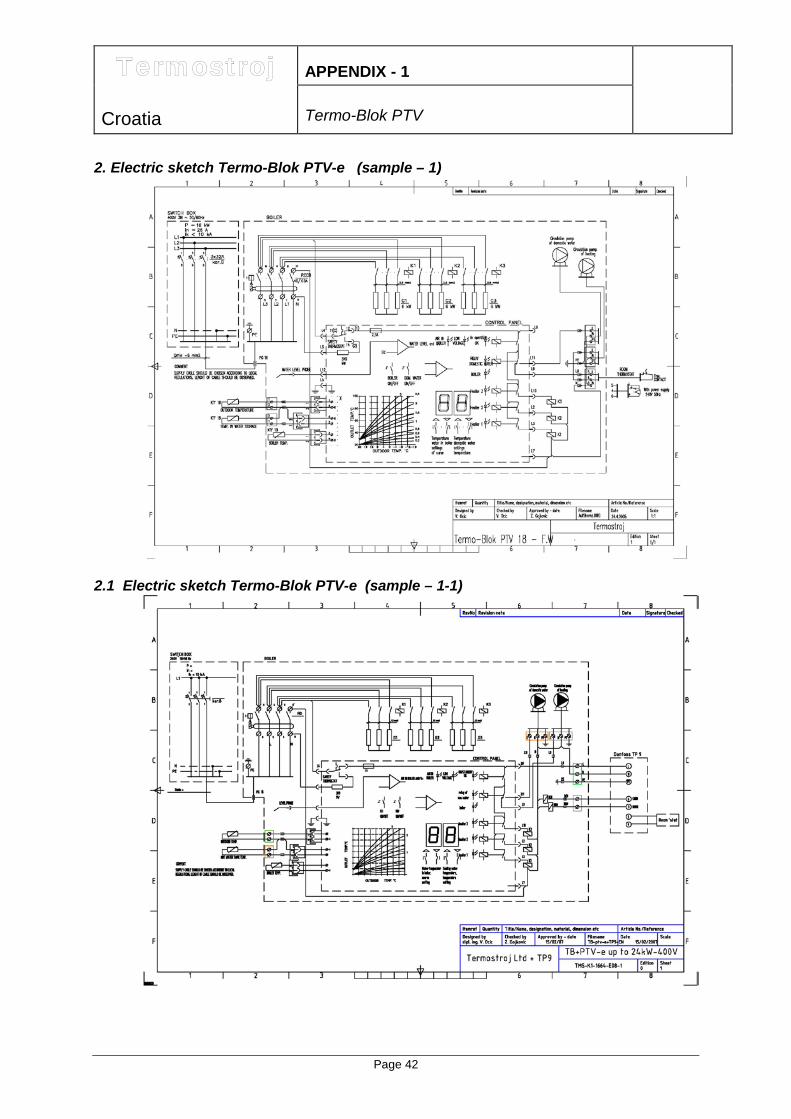
Termostroj
Croatia
APPENDIX - 1
Termo-Blok PTV
2. Electric sketch Termo-Blok PTV-e (sample – 1)
2.1 Electric sketch Termo-Blok PTV-e (sample – 1-1)
Page 42

Termostroj
Croatia
APPENDIX - 1
Termo-Blok PTV
3. Connection plate (sample – 1) 3. Connection plate (sample –1 – 1)
4. Control panel Termo PTV-e
1. Display 2. Led diodes of heaters stages 3. Led diode OK-air/standby 4. Led diode too low supply voltage 5. Led diode of central heating 6. Push-button for the adjustment of heating characteristics 7. Switch – heating AUTOMATIC/MANUAL 8. Push-button for adjusting characteristics of sanitary water conditioning 9. Sanitary water conditioning AUTOMATIC/MANUAL 10. Led diode in course of sanitary water conditioning 11. Indicator of water pressure in the heating system 12. Safety thermostat
Page 43

Termostroj
Croatia
APPENDIX - 2
Termo-Extra-e
Contains: 1. Hydraulic sketch 3. Connection plate 2. Electric sketch 4. Control panel
1. Hydraulic sketch Termo-Extra-e with room 'stat (sample - 2)
Basic characteristics: This sample of central heating system is combined with DHW cylinder and indirect heating system with the electric boiler up to 96 kW 400 V 3 N ~ 50Hz. This sample is similar to the system shown on sample - 1 but with bigger power of electric boiler. Electronic control panel uses the outside temperature information (with outside temperature probe) and automatically adjusts the temperature level in the boiler - radiators or under floor heating system. It is very simple to adjust the building or apartment insulations characteristics on the control panel. Sanitary water probe (supplied) must be installed into the water cylinder because the control panel needs information about domestic water temperature level. Domestic hot water has priority. Room ‘stat is recommended. By using the room ‘stat you can program several periods in a day via day temperature or reduced temperature level. In the standby position (only green led diode light) the boiler has antifreeze protection for central heating water and water in the cylinder.
Page 44

Termostroj
Croatia
APPENDIX - 2
Termo-Extra-e
1.1 Hydraulic sketch Termo-Extra-e with programmer (sample - 2-1)
Basic characteristics: Basic characteristics are the same as in the sample- 2, but with programmer (Danfoss TP-9 7-day programmer or similar) you have an opportunity to separate the periods of central heating program from the periods for preparing sanitary hot water. The switches 7 and 9 on electronic control panel have a different function when 7-day control unit for central heating and sanitary water preparing is installed. In this case position ‘’0’’ is AUTO and position ‘’1’’ is MANUAL. When sanitary water and apartment temperature rise to the desired level, the boiler automatically goes to standby position (everything is switched off except the standby led diode). It is mode for save energy (and money).
Page 45

Termostroj
Croatia
APPENDIX - 2
Termo-Extra-e
2. Electric sketch Termo-Extra-e (sample - 2)
2.1 Electric sketch Termo-Extra-e (sample - 2-1)
Page 46

Termostroj
Croatia
APPENDIX - 2
Termo-Extra-e
3. Connection plate (sample - 2) 3.1 Connection plate (sample - 2 - 1)
4. Control panel Termo-Extra-e
1. Display 2. Led diodes of heaters stages 3. Led diode OK-air/standby 4. Led diode too low supply voltage 5. Led diode of central heating 6. Push-button for adjustment of heating characteristics 7. Switch – heating AUTOMATIC/MANUAL 8. Push-button for adjusting characteristics of sanitary water conditioning 9. Sanitary water conditioning AUTOMATIC/MANUAL 10. Led diode in course of sanitary water conditioning 11. Indicator of water pressure in heating system 12. Safety thermostat
Page 47

Termostroj
Croatia
APPENDIX - 3
Termo-Blok PTV-m
Contains:
1. Hydraulic sketch 3. Connection plate 2. Electric sketch 4. Control panel
1. Hydraulic sketch Termo-Blok PTV-m with programmer (sample - 3)
Basic characteristics: This sample of central heating system is used in combination with DHW cylinder and heat exchanger that is built in it. Electromechanical control panel uses capillary thermostats to regulate temperature in the boiler and cylinder. With central heating programmer (Danfoss TP-9 7-day programmer or similar) you have an opportunity to separate the periods of central heating program from the periods for preparing sanitary hot water. Domestic hot water can have priority or does not have to. Room ‘stat is recommended. By using the room ‘stat you can program several periods in a day via day temperature or reduced temperature level. When sanitary water and apartment temperature rise to the desired level, the boiler goes to the standby position (everything is switched off) by Danfoss control unit TP9. It is energy saving mode (and money saving mode).
Page 48
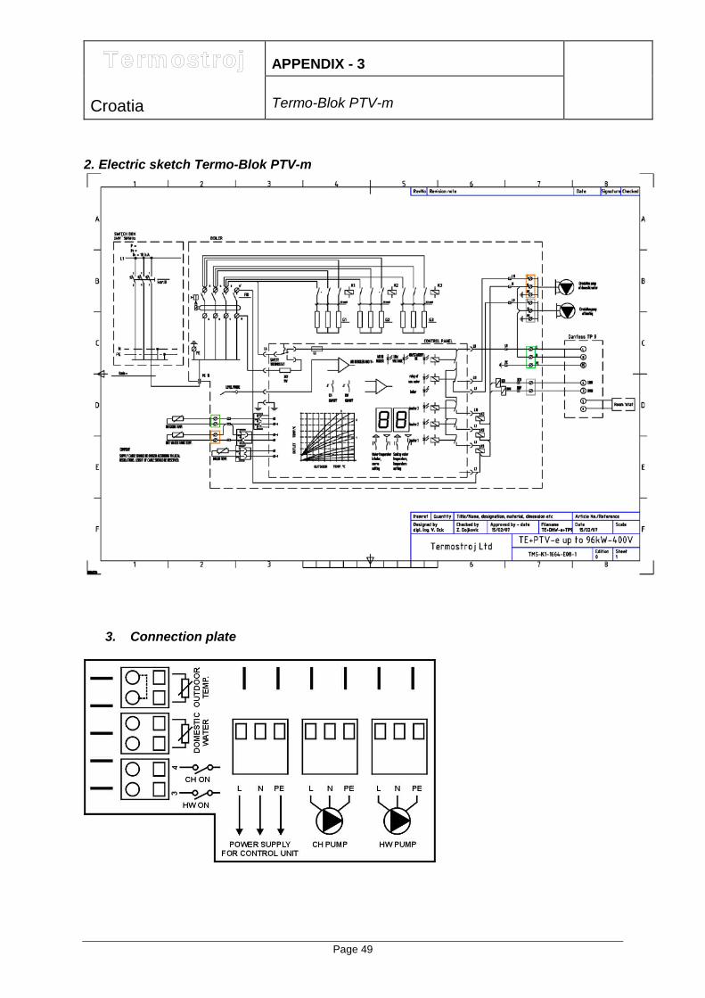
Termostroj
Croatia
APPENDIX - 3
Termo-Blok PTV-m
2. Electric sketch Termo-Blok PTV-m
3. Connection plate
Page 49

Termostroj
Croatia
APPENDIX - 3
Termo-Blok PTV-m
4. Control panel Termo-Blok PTV-m
Automatics consists of the following elements:
1. INDICATOR OF TEMPERATURE /PRESSURE IN BOILER 2. TEMPERATURE REGULATOR - capillary thermostat 3. SWITCH FOR THE 2ND AND 3RD OPERATION STAGE 4. LIMITING THERMOSTATE WITH MANUAL DEACTIVATION (switches off on ca 115 oC) 5. INDICATOR OF AIR APPEARANCE IN THE BOILER - air-indicator 6. SWITCH FOR AUTOMATICS’ FEEDING WITH 220V + 1ST OPERATION STAGE 7. GLAS FUSE 2,5A PROTECTING THE PUMP AND SWITCHES 8. INDICATION OF HEATER OPERATION 9. INDICATES LOW VOLTAGE PROTECTION - UNDER 180V
Page 50

Termostroj
Croatia
APPENDIX - 4
Termo-Extra-m
Contain:
1. Hydraulic sketch 3. Connection plate 2. Electric sketch 4. Control panel
1. Hydraulic sketch Termo-Extra-m with programmer (sample - 4)
Basic characteristics: This sample of central heating system is combined with DHW cylinder and the heat exchanger that is built in it. Termo-Extra boiler has temperature automatics only (working and safety) and the rest of the equipment has to be added (pumps, expansion vessel, security valve, etc…). Electromechanical control panel uses capillary thermostats to regulate temperature in the boiler and cylinder. With central heating programmer (Danfoss TP-9 7-day programmer or similar) you have an opportunity to separate the periods of central heating program from the periods for preparing sanitary hot water. Domestic hot water can have priority or does not have to. Room ‘stat is recommended. By using the room ‘stat you can program several periods in a day via day temperature or reduced temperature level When sanitary water and apartment temperature rise to the desired level, the boiler goes to the standby position (everything is switched off) by Danfoss control unit TP9. It is energy saving mode (and money saving mode).
Page 51
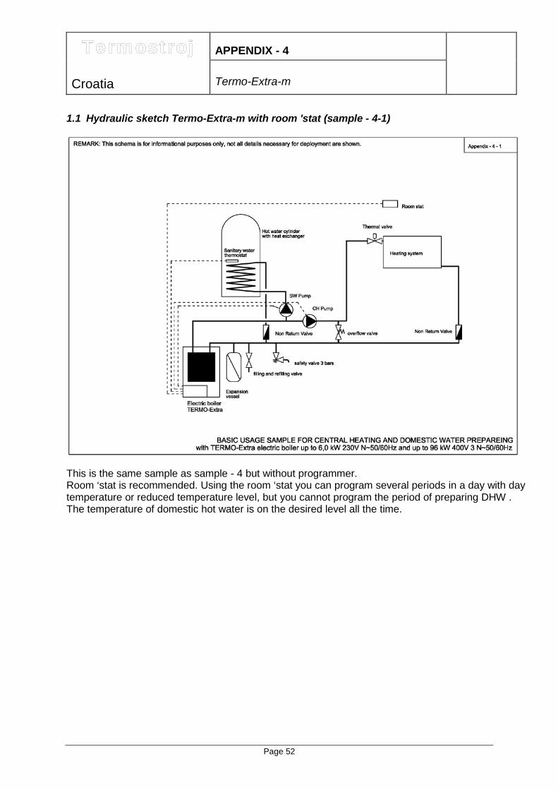
Termostroj
Croatia
APPENDIX - 4
Termo-Extra-m
1.1 Hydraulic sketch Termo-Extra-m with room 'stat (sample - 4-1)
This is the same sample as sample - 4 but without programmer. Room ‘stat is recommended. Using the room ‘stat you can program several periods in a day with day temperature or reduced temperature level, but you cannot program the period of preparing DHW . The temperature of domestic hot water is on the desired level all the time.
Page 52

Termostroj
Croatia
APPENDIX - 4
Termo-Extra-m
2. Electric sketch Termo-Extra-m (sample - 4)
3. Connection plate (sample - 4)
3.1 Connection plate (sample - 4-1)
Page 53

Termostroj
Croatia
APPENDIX - 4
Termo-Extra-m
4. Control panel Termo-Extra-m
Automatics consists of the following elements:
1 - INDICATOR OF TEMPERATURE /PRESSURE IN BOILER 2 - TEMPERATURE REGULATOR - capillary thermostat 3 - SWITCH FOR THE 2ND AND 3RD OPERATION STAGE 4 - LIMITING THERMOSTATE WITH MANUAL DEACTIVATION (switches off on ca 115 oC) 5 - INDICATOR OF AIR APPEARANCE IN THE BOILER - air-indicator 6 - SWITCH FOR AUTOMATICS’ FEEDING WITH 220V + 1ST OPERATION STAGE 7 - GLAS FUSE 2,5A PROTECTING THE PUMP AND SWITCHES 8 - INDICATION OF HEATER OPERATION 9 - INDICATES LOW VOLTAGE PROTECTION - UNDER 180V
Page 54

Termostroj
Croatia
APPENDIX - 5
Termo-Blok-e
Contains: 1. Hydraulic sketch 3. Connection plate 2. Electric sketch 4. Control panel
1. Hydraulic sketch Termo-Blok-e with room 'stat (sample - 5)
Basic characteristics: This is the sample of central heating system - radiators or under floor. Termo-Blok type boilers have power range from 6 up to 40 kW. Electronic control panel uses the outside temperature information (with outside temperature probe) and automatically adjusts the temperature level in the boiler - radiators or under floor heating system. It is very simple to adjust the building or apartment insulations characteristics on the control panel. Room ‘stat is recommended. By using the room ‘stat you can program several periods in a day via day temperature or reduced temperature level. In the standby position (only green led diode light) the boiler has antifreeze protection for central heating water.
Page 55

Termostroj
Croatia
APPENDIX - 5
Termo-Blok-e
2. Electric sketch Termo-Blok-e
3. Connection plate
Page 56
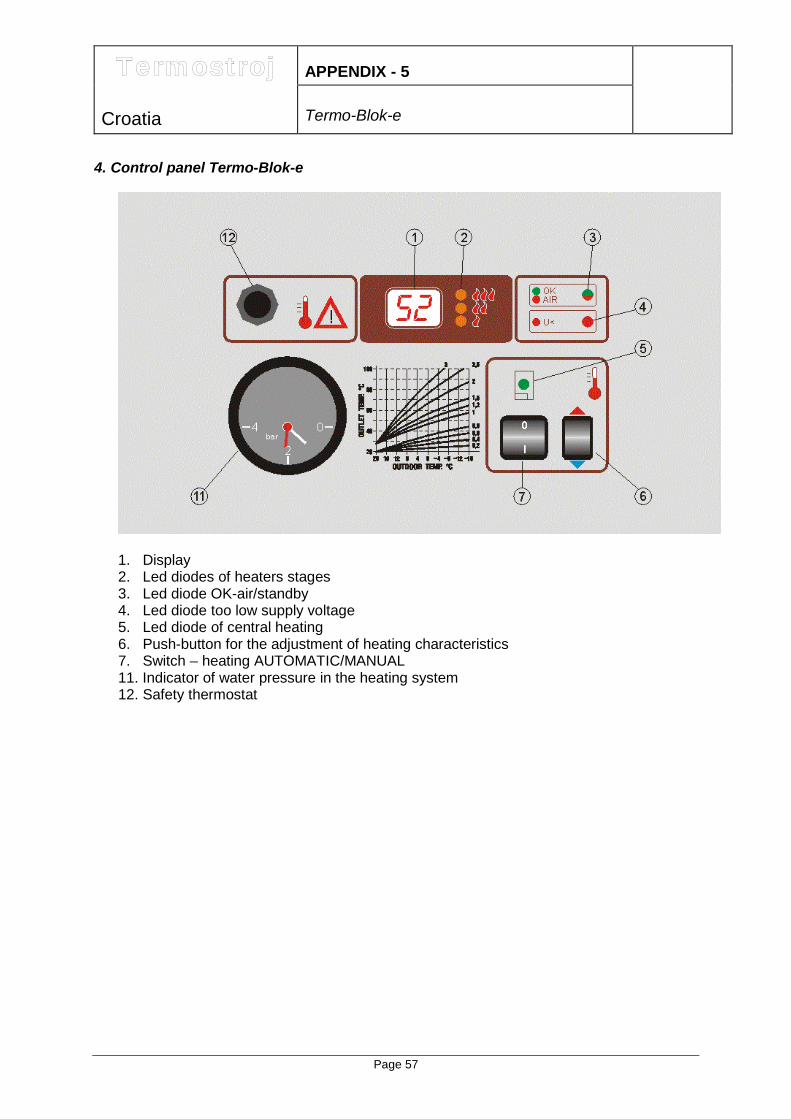
Termostroj
Croatia
APPENDIX - 5
Termo-Blok-e
4. Control panel Termo-Blok-e
1. Display 2. Led diodes of heaters stages 3. Led diode OK-air/standby 4. Led diode too low supply voltage 5. Led diode of central heating 6. Push-button for the adjustment of heating characteristics 7. Switch – heating AUTOMATIC/MANUAL 11. Indicator of water pressure in the heating system 12. Safety thermostat
Page 57

Termostroj
Croatia
APPENDIX - 6
Termo-Extra-e
Contains: 1. Hydraulic sketch 3. Connection plate 2. Electric sketch 4. Control panel
1. Hydraulic sketch Termo-Extra-e with room 'stat (sample - 6)
Basic characteristics: This is a sample of central heating system - radiators or under floor. Termo-Extra type boilers have power range from 6 up to 96 kW. Electronic control panel uses the outside temperature information (with outside temperature probe) and automatically adjusts the temperature level in the boiler - radiators or under floor heating system. It is very simple to adjust the building or apartment insulations characteristics on the control panel. Room ‘stat is recommended. By using the room ‘stat you can program several periods in a day via day temperature or reduced temperature level. In the standby position (only green led diode light) the boiler has antifreeze protection for central heating water.
Page 58

Termostroj
Croatia
APPENDIX - 6
Termo-Extra-e
2. Electric sketch Termo-Extra-e
3. Connection plate
Page 59

Termostroj
Croatia
APPENDIX - 6
Termo-Extra-e
4. Control panel Termo-Extra-e
1. Display 2. Led diodes of heaters stages 3. Led diode OK-air/standby 4. Led diode too low supply voltage 5. Led diode of central heating 6. Push-button for the adjustment of heating characteristics 7. Switch – heating AUTOMATIC/MANUAL 11. Indicator of water pressure in the heating system 12. Safety thermostat
Page 60
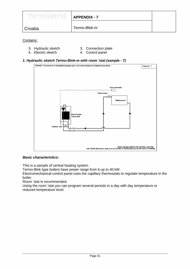
Termostroj
Croatia
APPENDIX - 7
Termo-Blok-m
Contains:
3. Hydraulic sketch 3. Connection plate 4. Electric sketch 4. Control panel
1. Hydraulic sketch Termo-Blok-m with room 'stat (sample - 7)
Basic characteristics: This is a sample of central heating system. Termo-Blok type boilers have power range from 6 up to 40 kW. Electromechanical control panel uses the capillary thermostats to regulate temperature in the boiler. Room ‘stat is recommended. Using the room ‘stat you can program several periods in a day with day temperature or reduced temperature level.
Page 61
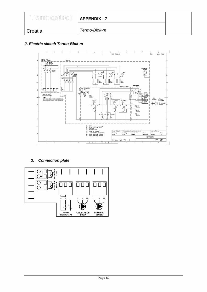
Termostroj
Croatia
APPENDIX - 7
Termo-Blok-m
2. Electric sketch Termo-Blok-m
3. Connection plate
Page 62
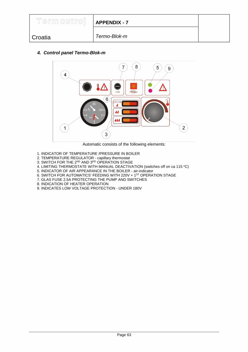
Termostroj
Croatia
APPENDIX - 7
Termo-Blok-m
4. Control panel Termo-Blok-m
Automatic consists of the following elements:
1. INDICATOR OF TEMPERATURE /PRESSURE IN BOILER 2. TEMPERATURE REGULATOR - capillary thermostat 3. SWITCH FOR THE 2ND AND 3RD OPERATION STAGE 4. LIMITING THERMOSTATE WITH MANUAL DEACTIVATION (switches off on ca 115 oC) 5. INDICATOR OF AIR APPEARANCE IN THE BOILER - air-indicator 6. SWITCH FOR AUTOMATICS’ FEEDING WITH 220V + 1ST OPERATION STAGE 7. GLAS FUSE 2,5A PROTECTING THE PUMP AND SWITCHES 8. INDICATION OF HEATER OPERATION 9. INDICATES LOW VOLTAGE PROTECTION - UNDER 180V
Page 63

Termostroj
Croatia
APPENDIX - 8
Termo-Extra-m
Contains:
1. Hydraulic sketch 3. Connection plate 2. Electric sketch 4. Control panel
1. Hydraulic sketch Termo-Extra-m with room 'stat (sample - 8)
Basic characteristics: This is a sample of central heating system. Termo-Extra type boilers have power range from 6 up to 96 kW. Electromechanical control panel uses the capillary thermostats to regulate temperature in the boiler. Room ‘stat is recommended. Using the room ‘stat you can program several periods in a day with day temperature or reduced temperature level.
Page 64

Termostroj
Croatia
APPENDIX - 8
Termo-Extra-m
2. Electric sketch Termo-Extra-m
3. Connection plate
Page 65

Termostroj
Croatia
APPENDIX - 8
Termo-Extra-m
4. Control panel Termo-Extra-m
Automatic consists of the following elements:
1. INDICATOR OF TEMPERATURE /PRESSURE IN BOILER 2. TEMPERATURE REGULATOR - capillary thermostat 3. SWITCH FOR THE 2ND AND 3RD OPERATION STAGE 4. LIMITING THERMOSTATE WITH MANUAL DEACTIVATION (switches off on ca 115 oC) 5. INDICATOR OF AIR APPEARANCE IN THE BOILER - air-indicator 6. SWITCH FOR AUTOMATICS’ FEEDING WITH 220V + 1ST OPERATION STAGE 7. GLAS FUSE 2,5A PROTECTING THE PUMP AND SWITCHES 8. INDICATION OF HEATER OPERATION 9. INDICATES LOW VOLTAGE PROTECTION - UNDER 180V
Page 66

TRGOVINA TERMOSTROJ d.o.o. 10250 Lučko, F. Puškarića 1d Tel/Fax +385 1 6531-008, 6531-015, 6531-016 Eurposka unija
e-mail: [email protected] web: http://www.termostroj.com European Union Contains:
1. Hydraulic sketch 3. Connection plate 2. Electric sketch 4. Control panel
1. Hydraulic sketch Termo-Blok-m with DHW cylinder (sample - 9)
Basic characteristics: This sample is a very usual system used for preparing DHW in cylinder with a heat exchanger. Termo-Blok type boilers have power range from 6 up to 40 kW. If you need more power you can use Termo-Extra type boilers with max. power 96 kW. The capacity of cylinder that you can use is from 80 up to 5.000 lit. Electromechanical control panel uses the capillary thermostats to regulate temperature in the boiler. Recommended boiler temperature is about 80 oC. You can adjust the desired temperature of DHW on the cylinder thermostat.
INSTALACIJSKE UPUTE Zadržavamo pravo izmjene uputa bez posebne najave

TRGOVINA TERMOSTROJ d.o.o. 10250 Lučko, F. Puškarića 1d Tel/Fax +385 1 6531-008, 6531-015, 6531-016 Eurposka unija
e-mail: [email protected] web: http://www.termostroj.com European Union 2. Electric sketch Termo-Blok-m with DHW cylinder
3. Connection plate
INSTALACIJSKE UPUTE Zadržavamo pravo izmjene uputa bez posebne najave

TRGOVINA TERMOSTROJ d.o.o. 10250 Lučko, F. Puškarića 1d Tel/Fax +385 1 6531-008, 6531-015, 6531-016 Eurposka unija
e-mail: [email protected] web: http://www.termostroj.com European Union 4. Control panel Termo-Blok-m
Automatic consists of the following elements:
1. INDICATOR OF TEMPERATURE /PRESSURE IN BOILER 2. TEMPERATURE REGULATOR - capillary thermostat 3. SWITCH FOR THE 2ND AND 3RD OPERATION STAGE 4. LIMITING THERMOSTATE WITH MANUAL DEACTIVATION (switches off on ca 115 oC) 5. INDICATOR OF AIR APPEARANCE IN THE BOILER - air-indicator 6. SWITCH FOR AUTOMATICS’ FEEDING WITH 220V + 1ST OPERATION STAGE 7. GLAS FUSE 2,5A PROTECTING THE PUMP AND SWITCHES 8. INDICATION OF HEATER OPERATION 9. INDICATES LOW VOLTAGE PROTECTION - UNDER 180V
‘Ulaganje u budućnost’ ‘Investing for the future’
Projekt sufinancira Europska unija iz Europskog fonda za regionalni razvoj. Project is co-founded by the European Union’s Regional Development Fond.
INSTALACIJSKE UPUTE Zadržavamo pravo izmjene uputa bez posebne najave

Termostroj
Croatia
APPENDIX - 9
Termo-Blok-m with DHW cylinder
INSTALACIJSKE UPUTE Zadržavamo pravo izmjene uputa bez posebne najave

TRGOVINA TERMOSTROJ d.o.o. 10250 Lučko, F. Puškarića 1d Tel/Fax +385 1 6531-008, 6531-015, 6531-016 Eurposka unija
e-mail: [email protected] web: http://www.termostroj.com European Union
ELECTRIC BOILER FOR CENTRAL HEATING
AND WARM WATER PREPARATION
TERMO-Kombi USER’S INSTRUCTIONS
‘Ulaganje u budućnost’ ‘Investing for the future’
Projekt sufinancira Europska unija iz Europskog fonda za regionalni razvoj. Project is co-founded by the European Union’s Regional Development Fond.
We reserve the right of changing these instructions without special prior notification

TRGOVINA TERMOSTROJ d.o.o. 10250 Lučko, F. Puškarića 1d Tel/Fax +385 1 6531-008, 6531-015, 6531-016 Eurposka unija
e-mail: [email protected] web: http://www.termostroj.com European Union WE ARE NOT LIABLE FOR DAMAGES RESULTING FROM NON-OBSERVING
THESE INSTRUCTIONS
TERMOSTROJ d.o.o. 10250 ZAGREB – LUČKO, F. Puškarića 1d, PP31
Tel/Fax +385 1 6531008, 6531015,6531016
e-mail: [email protected] web: http://www.termostroj.com
Table of contents
1. Introduction .............................................................. 1
2. About the product .................................................... 1
2.1. Construction ..................................................... 1
2.2. Integral parts of the TERMO-Kombi Boiler ...... 2
3. Installation ............................................................... 3
3.1. Important warnings ........................................... 3
3.2. Assembly .......................................................... 3
3.2. Assembly (Continued) ...................................... 4
3.3. Connection to the power network .................... 5
3.4. Connection of room thermostat ........................ 5
4. Use of the product ................................................... 6
4.1. Use of the boiler ............................................... 7
4.2. Manipulation with automatic equipment ........... 8
4.4. Recommendations for optimal use ................11
5. Maintenance ..........................................................11
6. Survey of possible defects and irregularities in
operation ...................................................................13
7. Technical specification ..........................................15
We reserve the right of changing these instructions without special prior notification TMS-UT-1203-Z07-2

TRGOVINA TERMOSTROJ d.o.o. 10250 Lučko, F. Puškarića 1d Tel/Fax +385 1 6531-008, 6531-015, 6531-016 Eurposka unija
e-mail: [email protected] web: http://www.termostroj.com European Union
1. Introduction Thank you for the confidence you have shown to us by having purchased our boiler for central heating and sanitary water preparation. For correct and safe and above all economic use of the product, before assembly and connection, read thoroughly these instructions. Packing contains the following elements: boiler (1), suspension support (3), user’s instructions and letter of guarantee (3), valve for filling and emptying (4), impurities collector (5), plastic pipe for venting the system. The Termo-Kombi boilers meet any and all national regulations and legal standards. Pursuant to the mentioned before, the certification of the product was done according to the valid EN and HRN standards. You can take insight into the certificates at the point of sale, authorized service or web sites: http:/www.termostroj.hr. The firm Termostroj is certified by the quality system pursuant with the standard ISO 9001:2000.
Illustration of unpacked product
2. About the product TERMO-Kombi is the economic boiler for central heating and sanitary water preparation that may be used as the independent source of heat. The boiler is operated on the principle of rapid heating smaller water quantities and its energy exploitation is almost 100% TERMO-Kombi is suitable for using in smaller business premises, flats, smaller catering objects etc., where it is important that it takes up small space. Temperature range of operation is for sanitary water from 30oC up to 55 oC, for central heating from 30oC up to 90 oC. Because of its design and noise free operation, the TERMO-Kombi may easily fit in the living space. The outer metal sheet is protected by plastification.
2.1. Construction The electric boiler TERMO-Kombi is made of quality boiler metal sheet. The boiler itself is upon welding sandblasted and protected with quality reactive fundamental color. At the bottom side of the boiler there are built in electric heaters. From the upper side there is the blind tube for placing the sounding tube of capillary thermostat, temperature, pressure and thermal fuse indicator. The boiler is insulated with 19 mm self extinguishing insulating material Armaflex, which is sufficient to direct all the heat only to the heating and sanitary water preparation system.
We reserve the right of changing these instructions without special prior notification TMS-UT-1203-Z07-2 1

TRGOVINA TERMOSTROJ d.o.o. 10250 Lučko, F. Puškarića 1d Tel/Fax +385 1 6531-008, 6531-015, 6531-016 Eurposka unija
e-mail: [email protected] web: http://www.termostroj.com European Union
2.2. Integral parts of the TERMO-Kombi Boiler 1. Central heating primary flow 2. Central heating return flow 3. External shell of the boiler 4. Boiler 5. Thermal insulation 6. Electric heaters 7. Control panel 8. Boots for el. terminals 9. Contactors 10. Expansion vessel 11. Central heating pump 12. Safety valve at 3 bar 13. Automatic venting pot 14. Filling and emptying valve (in packing, it should
be built in at installation) 15. Valve for boiler venting 16. Sounding tube for air appearance control 17. Distributor 18. RCCB switch 19. Temperature sensor of sanitary water outlet line 20. Exchanger 21. Temperature sensor of sanitary water inlet line 22. Non-return valve 23. Pump for sanitary water preparation 24. Sanitary water intake 25. Sanitary water output 26. Safety valve at 8 bar
We reserve the right of changing these instructions without special prior notification TMS-UT-1203-Z07-2 2

TRGOVINA TERMOSTROJ d.o.o. 10250 Lučko, F. Puškarića 1d Tel/Fax +385 1 6531-008, 6531-015, 6531-016 Eurposka unija
e-mail: [email protected] web: http://www.termostroj.com European Union
3. Installation
3.1. Important warnings THE GUARANTEE SHALL NOT BE ACCEPTED IF THE FOLLOWING WAS NOT OBSERVED: • THE BOILER SHOULD BE PUT INTO
OPERATION BY THE AUTHORIZED SERVICE, • THE ENCLOSED IMPURITIES COLLECTOR
SHOULD BE BUILT IN ON THE STARTING LINE OF CENTRAL HEATING AND INLET COLD SANITARY WATER,
• PRIOR TO CONNECTING THE BOILER TO THE SANITARY WATER LINE, PIPES SHOULD BE CLEANED IN ORDER TO AVOID THE BLOCKAGE OF THE EXCHANGER.
THE LIST OF AUTHORIZED SERVICES IS ON THE BACK OF THE LETTER OF GUARANTEE THE BOILER SHOULD NOT BE INSTALLED ON PLACEC WHERE THERE IS A DANGER OF BEING PORING OVER WITH WATER OR A DANGER OF SINKING. IN AREAS WITH STRONG CONCENTRATION OF LIME IT IS RECOMMENDED TO BUILD IN A MAGNETIC OR ELECTROMAGNETIC LIME BREAKER ON THE INLET LINE OF SANITARY WATER ON THE BOILER.
3.2. Assembly TERMO-Kombi is foreseen for the wall assembly and for the easier assembly, on the backside there is foreseen the suspension support. For the suspension you may use metal wall plugs with the screw M8 or M10 or stronger plastic wall plugs – diana screws. Precise dimensions of boilers are given in the 7. Technical specification Filling and emptying valve is delivered together with the boiler and should be assembled at the installation. If possible, the boiler should be assembled to the lowest point in relation to installation. In this way we are protecting the boiler from air appearance, which may leave heaters without water that could result in their burning through.
Minimum distances at assembly
Disassembly schema
We reserve the right of changing these instructions without special prior notification TMS-UT-1203-Z07-2 3
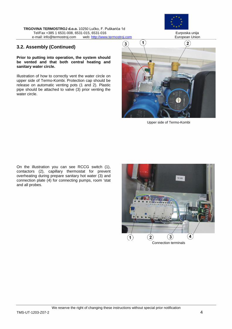
TRGOVINA TERMOSTROJ d.o.o. 10250 Lučko, F. Puškarića 1d Tel/Fax +385 1 6531-008, 6531-015, 6531-016 Eurposka unija
e-mail: [email protected] web: http://www.termostroj.com European Union
3.2. Assembly (Continued) Prior to putting into operation, the system should be vented and that both central heating and sanitary water circle. Illustration of how to correctly vent the water circle on upper side of Termo-Kombi. Protection cap should be release on automatic venting pots (1 and 2). Plastic pipe should be attached to valve (3) prior venting the water circle. On the illustration you can see RCCG switch (1), contactors (2), capillary thermostat for prevent overheating during prepare sanitary hot water (3) and connection plate (4) for connecting pumps, room ‘stat and all probes.
Upper side of Termo-Kombi
Connection terminals
We reserve the right of changing these instructions without special prior notification TMS-UT-1203-Z07-2 4

TRGOVINA TERMOSTROJ d.o.o. 10250 Lučko, F. Puškarića 1d Tel/Fax +385 1 6531-008, 6531-015, 6531-016 Eurposka unija
e-mail: [email protected] web: http://www.termostroj.com European Union
3.3. Connection to the power network For power supply connection on all Termo-Kombi boilers, RCCB switch is used, providing same time protection for boiler and connection point for external power cables.
3.4. Connection of room thermostat The TERMO-Kombi boiler has foreseen clamps for connecting the room thermostat. The short circuit is factory installed on the clamps (for cases when the room thermostat is not used) and if we connect it, we have to take account of the fact, which type of a room thermostat is to be connected. One group of thermostats is connected only serially in the control voltage circuit, resp. on clamps. The other group of thermostats has built in temperature simulation system and therefore should be constantly under voltage and according to the fixed temperature in the room, on its outlet we have the signal for boiler control. In this case the ZERO-line is connected to the clamp “N”. Read instructions for connection of a thermostat, which are enclosed to the thermostat in order to learn which way of connection is laid down by the producer.
Power supply connection
Room thermostat terminal
We reserve the right of changing these instructions without special prior notification TMS-UT-1203-Z07-2 5

TRGOVINA TERMOSTROJ d.o.o. 10250 Lučko, F. Puškarića 1d Tel/Fax +385 1 6531-008, 6531-015, 6531-016 Eurposka unija
e-mail: [email protected] web: http://www.termostroj.com European Union
4. Use of the product Control panel
1. Multipurpose – temperature indicator (temperature of
boiler, sanitary water, adjustment of temperature)
2. Signalization of operation degree of heaters (1., 2., 3.)
3. Signalization of air appearance in the boiler (red light)
4. Signalization of under voltage protection (red light)
5. Signalization of boiler operation (green light)
6. Adjustment of temperature in boiler
7. Switch for central heating switching on and off
8. Sanitary water temperature adjustment
9. Switch for switching on and off the sanitary water
preparation
10. Signalization of sanitary water preparation and
consumption
11. Indicator of pressure in a boiler
12. Thermal fuse
We reserve the right of changing these instructions without special prior notification TMS-UT-1203-Z07-2 6

TRGOVINA TERMOSTROJ d.o.o. 10250 Lučko, F. Puškarića 1d Tel/Fax +385 1 6531-008, 6531-015, 6531-016 Eurposka unija
e-mail: [email protected] web: http://www.termostroj.com European Union
4.1. Use of the boiler First putting on at the beginning of a season For the first putting on at the beginning of a central heating season, the first step should be to put on the boiler by means of the switch for central heating (7), temperature in the boiler (1) should be adjusted to 30°C (in this was the heaters are disconnected and only circulation pump is in operation). Warm water preparation is put on by means of the switch for sanitary water (9) If upon putting on the boiler there is no noise of water or the central heating if warm water pump does not run (during operation, the pump produces slight vibrations) the pump should be manually started. Circulation pumps lubricate bearings with water flowing through the pump and after stoppage it could occur that the bearings “burn”. Starting the pump For starting the pump it is necessary to turn off the protection plug on its front side (1) below which there is the axis with the groove for screwdriver. With the screwdriver, the pump (2) should be several times turned in direction of the arrow on the pump head and the boiler should be put on again. When the pump starts, the operation temperature of water in boiler and temperature of sanitary water should be selected. For central heating the optimal temperature is between 60 and 70°C, whereas for sanitary water optimal temperature ranges from 45 to 48°C. If to the boiler a room thermostat is connected, a desired room temperature should be adjusted according to the instructions of the producer of room thermostat.
Segment of control panel
We reserve the right of changing these instructions without special prior notification TMS-UT-1203-Z07-2 7

TRGOVINA TERMOSTROJ d.o.o. 10250 Lučko, F. Puškarića 1d Tel/Fax +385 1 6531-008, 6531-015, 6531-016 Eurposka unija
e-mail: [email protected] web: http://www.termostroj.com European Union
4.2. Manipulation with automatic equipment Putting on and of the sanitary water preparation The boiler is switched on by means of the main switch (9), for switching on, the switch should be put in the position 1. Upon switching on a desired water temperature in boiler is displayed for 5 seconds, signalization of sanitary water preparation is twinkling (10). Upon 5 seconds real temperature of sanitary water outlet is displayed (1); if there is no requirement for sanitary water, the signalization lamp of sanitary water preparation (10) is switched off. By switching the switch (9) to the position 0, the sanitary water preparation is put off. The entered desired temperature of sanitary water shall be stored. Adjustment of desired temperature of sanitary water By pressing the key for temperature adjustment (8) the desired warm water temperature appears, the signalization lamp of sanitary water preparation (10) is twinkling. By repeated pressing upwards or downwards it is possible to increase or decrease the desired sanitary water temperature. When the temperature is adjusted it is sufficient to wait for 5 seconds (signalization lamp of sanitary water preparation (10) does not twinkle) in order that the boiler memorizes a new temperature. Use of sanitary water If there is a need for sanitary water, the signalization lamp of sanitary water preparation turns on (10) and the temperature of warm water outlet displays. Signalization of operation degree of heaters (2) displays and by turning on lamps it is shown whether one group of heaters is in operation, two or all three groups. The boiler automatically controls a heater operation degree. Putting on central heating By switching the switch (7) to the position 1, the central heating system is switched on. Upon switching on a desired water temperature in boiler is displayed for 5 seconds, signalization of boiler operation is twinkling (5). Upon 5 seconds real temperature in the boiler is displayed (1); if the current temperature in boiler meets the desired one, the signalization lamp of boiler operation (10) is switched off. Adjustment of desired temperature of central heating By pressing the key for temperature adjustment (6) the desired temperature in the boiler appears, the signalization lamp of boiler operation (5) is twinkling. By repeated pressing upwards or downwards it is possible to increase or decrease the desired sanitary water temperature. When the temperature is adjusted it is sufficient to wait for 5 seconds (signalization lamp of boiler operation (10) does not twinkle) in order that the boiler memorizes a new temperature.
Segment of control panel
Segment of control panel
We reserve the right of changing these instructions without special prior notification TMS-UT-1203-Z07-2 8

TRGOVINA TERMOSTROJ d.o.o. 10250 Lučko, F. Puškarića 1d Tel/Fax +385 1 6531-008, 6531-015, 6531-016 Eurposka unija
e-mail: [email protected] web: http://www.termostroj.com European Union
We reserve the right of changing these instructions without special prior notification TMS-UT-1203-Z07-2 9

TRGOVINA TERMOSTROJ d.o.o. 10250 Lučko, F. Puškarića 1d Tel/Fax +385 1 6531-008, 6531-015, 6531-016 Eurposka unija
e-mail: [email protected] web: http://www.termostroj.com European Union Parallel operation of central heating and sanitary water When both modes of operation are active, central heating and sanitary water preparation, the boiler prefers sanitary water. If there is a requirement for warm water, the boiler starts with preparation of sanitary water, the lamp (10) turns on, whereas the boiler operation signalization turns off (5); temperature indicator (1) displays the current temperature of warm water outlet. Air in the boiler (3), red light If in the boiler the air appears, the signalization of air in the boiler turns on (3) and the boiler stops the operation. In this way the boiler is protected against blowing because of appearance of air. For continuation of operation, the boiler should be vented. If the boiler is correctly vented, the operation of boiler continues automatically. Voltage drop (4), red light If the voltage in the network line drops below 180V by phase, the signalization of under voltage protection (4) turns on, the boiler automatically switches off in order to protect electronics and contactors inside the boiler. The boiler shall automatically continue the operation when the network voltage reaches values above 180V. Thermal fuse - turning on By means of thermal fuse (12) the boiler is protected against rapid increase of temperature above 115°C. The fuse turns off the boiler and ejects the FID-switch. For continuation of operation it is necessary to take off the protection cover from the thermal fuse and press the red key, upon which the FID-switch should be switched on again.
Segment of the control panel
Segment of the control panel
We reserve the right of changing these instructions without special prior notification TMS-UT-1203-Z07-2 10

TRGOVINA TERMOSTROJ d.o.o. 10250 Lučko, F. Puškarića 1d Tel/Fax +385 1 6531-008, 6531-015, 6531-016 Eurposka unija
e-mail: [email protected] web: http://www.termostroj.com European Union
4.4. Recommendations for optimal use Central heating For optimal use of the boiler and electric power consumption, we recommend the use of quality room thermostat connected to the boiler. Daily temperature should be between 20°C i 22°C (for each degree above 22°C the consumed energy is increasing exponentially). For the night operation we recommend temperature between 15 i 17 °C. In this way energy saving is higher than in case of complete turning off the boiler during the night. If there is no room thermostat, for night operation the temperature in boiler should be decreased to about 40°C or turned off completely (9. main switch). In summer period, valves below boiler should not be closed (closing valves disables water circulation in system (10 – 15 seconds) generated by safety thermostat. Warm water Optimal temperature of sanitary water, in boiler, is 42°C up to 45°C (above 48°C it comes to increased lime separation that sticks to the exchanger, tubes and pump and may lead to gradual decrease of boiler effect).
5. Maintenance We recommend the inspection of a device once a year by the authorized service (before heating season). This service is not included in the guarantee. During the inspection all electric and water connections should be tightened, the system should be vented and – if necessary – filled up, valves and general functionality of the device should be checked. If you notice a reduced effect of warm water it is necessary to remove lime accumulated within the plate exchanger (1). Only authorized service engineer can do removing lime. Prior to the beginning of cleaning, valves (2) separating the boiler from the sanitary water installation, should be closed. Cleaning tubes should be connected to the foreseen 1/2" piping (3) (internal thread). Cleaning solution (5) may be formic acid 2-3%, nitric acid 3-4% or acetic acid 10%. The solution should circulate through the system by a pump (4), as long as there is the sludge in the outlet pipe. Thereupon the direction of a circulation should be changed and the process repeated. Upon finished cleaning the boiler should be washed in the same way with clear water. For cleaning the product it is not permitted to use aggressive media as e.g. gasoline, kerosene or solvent. For the external shell and decorative cover media for cleaning
plastics or dish washing media may be used. Control panel should be cleaned with dry or moist cloth (not wet).
We reserve the right of changing these instructions without special prior notification TMS-UT-1203-Z07-2 11

TRGOVINA TERMOSTROJ d.o.o. 10250 Lučko, F. Puškarića 1d Tel/Fax +385 1 6531-008, 6531-015, 6531-016 Eurposka unija
e-mail: [email protected] web: http://www.termostroj.com European Union
Schematic illustration of lime removal
We reserve the right of changing these instructions without special prior notification TMS-UT-1203-Z07-2 12

TRGOVINA TERMOSTROJ d.o.o. 10250 Lučko, F. Puškarića 1d Tel/Fax +385 1 6531-008, 6531-015, 6531-016 Eurposka unija
e-mail: [email protected] web: http://www.termostroj.com European Union
6. Survey of possible defects and irregularities in operation
DEFECT CAUSE ELIMINATION - at switching on, no voltage on the control panel
- no feed from net on one or more phases
- fuse 2,5A on the control panel blown
- FID switch ejected
- check on serial clamps of the boiler whether there is feeding
- replace the fuse 2,5A and check the cause of its blowing
- at switching on, switches show voltage on the control board, but the boiler does not heat
- check the adjustment of a room thermostat,
- limit thermostat was activated,
- indicator of air appearance in the boiler blocked the operation,
- defective contactor, - defective operation
thermostat, - blown heaters
- check the adjusted temperature on a room thermostat, replace its batteries or it is defective,
- vent the boiler till the lamp “air in boiler”, turns off
- temperature in boiler is at the desired value, but the radiators are not warm
- circulation pump is not in operation,
- air blockage on central heating installation, that prevents the circulation
- start the mechanical pump or replace it with the new one if it is blown (see 4.1.),
- vent the installation
- the boiler heats poorly - on the feed one phase is missing,
- in two-phase thermostats, second phase is not in operation,
- second or third phase was not manually turned on,
- one contactor defective, - a part of the heater has
blown, - in three-phase system to
the boiler are not brought three various phases
- check fuses on the main panel,
- replace thermostat or, if necessary, contactor,
- replace the heater, - measure with the
instrument voltage between phases, it should be 380V
- in the operation the contactor can be heard (it is buzzing) and possibly radio and TV-interferences
- poor voltage in the network, - defective contactor
- select with the instrument the best phase for control (on the boiler marked with “R”)
- replace the contactor - at switching on or off the operation thermostat radio and TV-disturbances
- defective operation thermostat,
- defective blockade (RC – protection)
- replace the thermostat, - replace the RC – member
- boiler in operation is roaring - a system is not good vented,
- vent the system, - replace heaters
We reserve the right of changing these instructions without special prior notification TMS-UT-1203-Z07-2 13

TRGOVINA TERMOSTROJ d.o.o. 10250 Lučko, F. Puškarića 1d Tel/Fax +385 1 6531-008, 6531-015, 6531-016 Eurposka unija
e-mail: [email protected] web: http://www.termostroj.com European Union - defective heater
- pressure in heating system is varying
- defective expansion vessel, - too low or too high pressure
in the vessel
- if there is water on the valve for pumping the vessel, replace the vessel,
- pressure in the vessel should be 0,5 – 0,8 bar
- FID switch is ejecting - defective heater, - moist on conductors, - safety thermostat activated
- replace the heater, - check leaking, - check the cause of
activation
- FID switch can not be reset - safety thermostat activated - firstly reset the safety thermostat and then the FID switch
- sanitary water temperature is varying
- too low pressure or too small flow in plumbing installation
- set the warm water temperature to the desired temperature without mixing with cold water
- boiler does not reach a desired warm water temperature
- check network fuses - warm water flow is higher
than boiler capacity
- check in the instructions the maximum warm water flow
- boiler does not warm up a water
- pump for warm water preparation is not in operation
- air in warm water system
- start the pump manually according to the instructions in 4.1.
- vent the warm water system
We reserve the right of changing these instructions without special prior notification TMS-UT-1203-Z07-2 14

TRGOVINA TERMOSTROJ d.o.o. 10250 Lučko, F. Puškarića 1d Tel/Fax +385 1 6531-008, 6531-015, 6531-016 Eurposka unija
e-mail: [email protected] web: http://www.termostroj.com European Union
7. Technical specification
1. Central heating return line 2. Sanitary water inlet line (cold water) 3. Valve for venting the boiler 4. Central heating starting line 5. Sanitary water outlet line (warm water)
6. Control panel 7. Wall support for suspension 8. Safety valve at 6 bar 9. Safety valve at 3 bar 10. and 11. Network terminals (3 x 380V 50Hz)
TERMO-Kombi Boilers Type of the device
Characteristics Units TERMO Kombi 18
TERMO Kombi 24
TERMO Kombi 32
TERMO Kombi 40
Central heating heat effect kW 18 24 32 40 Warm water heat effect kW 18 24 32 40 Max. pump supply at 1000 lit/h m 4,8 4,8 4,8 4,8 Area of central heating temperature adjustment
oC 40 - 90 40 - 90 40 - 90 40 - 90
Area of warm water temperature adjustment oC 30 - 55 30 - 55 30 - 55 30 - 55 Warm water flow at 2 bar l/min 6,8 8,5 10,2 11,50 Warm water flow at 2 bar and 55oC l/min 3,10 4,00 5,10 5,8 Specific flow ( at ΔT - 30 K ) l/min 11,2 12,80 13,96 15,6 Permitted overpressure, warm water bar 6 6 6 6 Height mm 930 930 930 930
INSTALACIJSKE UPUTE Zadržavamo pravo izmjene uputa bez posebne najave

TRGOVINA TERMOSTROJ d.o.o. 10250 Lučko, F. Puškarića 1d Tel/Fax +385 1 6531-008, 6531-015, 6531-016 Eurposka unija
e-mail: [email protected] web: http://www.termostroj.com European Union Depth mm 220 220 220 220 Width mm 480 480 550 550 Weight ca kg 48 48 56 56
SUPPLY CHARACTERISTICS (EU based, 380V 3 N ~ 50/60 Hz)
POWER nominal current
fuse current Rated short-circuit
breaking capacity
Icn (EN 60898)
Rated short-circuit
breaking capacity
Icn (IEC 947-2)
min. conductor's cross-section
mm2*
Schrak fuses type
RCCB switch type
18 kW 27,35 A 32 A Kar. B
10 kA 15 kA
6 B 32/3
63 / 0,03 A 24 kW 36,45 A 40 A Kar. B
10
B40/3
32 kW 48,62 A 63 A Kar. B B 63/3
40 kW 60,76 A
‘Ulaganje u budućnost’ ‘Investing for the future’
Projekt sufinancira Europska unija iz Europskog fonda za regionalni razvoj. Project is co-founded by the European Union’s Regional Development Fond.
INSTALACIJSKE UPUTE Zadržavamo pravo izmjene uputa bez posebne najave

TRGOVINA TERMOSTROJ d.o.o. 10250 Lučko, F. Puškarića 1d Tel/Fax +385 1 6531-008, 6531-015, 6531-016 Eurposka unija
e-mail: [email protected] web: http://www.termostroj.com European Union
INSTALACIJSKE UPUTE Zadržavamo pravo izmjene uputa bez posebne najave