terracon consultants, inc. - · pdf filerevised geotechnical engineering study south laredo...
TRANSCRIPT

REVISED GEOTECHNICAL ENGINEERING STUDY
SOUTH LAREDO WASTE WATER TREATMENT PLANT (WWTP) LAREDO, TEXAS
Terracon Project No 89085091 March 24, 2009
Prepared For:
WATER UTILITIES DEPARTMENT CITY OF LAREDO LAREDO, TEXAS
Prepared By:
TERRACON CONSULTANTS, INC. LAREDO, TEXAS


South Laredo Waste Water Treatment Plant (WWTP) Project No. 89085091 March 24, 2009
TABLE OF CONTENTS
INTRODUCTION ..............................................................................................................................1 PROJECT DESCRIPTION................................................................................................................1 SITE EXPLORATION PROCEDURES.............................................................................................2
Field Exploration..........................................................................................................................2 Laboratory Testing ......................................................................................................................3 Chemical Testing.........................................................................................................................3
SITE CONDITIONS ..........................................................................................................................3 SUBSURFACE CONDITIONS..........................................................................................................3
Soil Conditions ............................................................................................................................3 Groundwater Conditions.............................................................................................................4
Piezometers ..............................................................................................................................5 ENGINEERING RECOMMENDATIONS ..........................................................................................5
Geotechnical Considerations .....................................................................................................6 Pad Preparation........................................................................................................................6
Slab Foundation...........................................................................................................................7 Construction Considerations..................................................................................................8
Mat Foundation ............................................................................................................................8 Construction Considerations..................................................................................................8
Spread Footing ............................................................................................................................9 Construction Considerations................................................................................................10
Concrete Ringwall Foundation.................................................................................................10 Construction Considerations................................................................................................11
Below-Grade Walls ....................................................................................................................15 Hydrostatic Pressure .............................................................................................................16
Seismic Design Criteria.............................................................................................................17 Presence of Potential Corrosive Conditions .......................................................................17
Pavements..................................................................................................................................17 Gravel/Prime Coat Pavement....................................................................................................17 Flexible and Rigid Pavement System ......................................................................................18
Flexible Pavement System ....................................................................................................19 Rigid Pavement System.........................................................................................................19 Pavement Section Materials ..................................................................................................20 Pavement Joints and Reinforcement ...................................................................................23
Underground Utility Design Recommendations.....................................................................25 Trench Bearing Pressures.....................................................................................................25 Buoyant Uplift .........................................................................................................................25 Modulus of Soil Reaction.......................................................................................................25
Earthwork ...................................................................................................................................28 Earthwork ...................................................................................................................................28
Site Access .............................................................................................................................28 Structure Pad and Pavement Subgrade Preparation ..........................................................29 Select Fill Materials ................................................................................................................29
i

South Laredo Waste Water Treatment Plant (WWTP) Project No. 89085091 March 24, 2009
TABLE OF CONTENTS (CONTINUED)
Excavations................................................................................................................................30
Shoring....................................................................................................................................30 Trenches .................................................................................................................................30 Occupational Safety and Health Administration (OSHA) Guidelines ................................30
GENERAL COMMENTS.................................................................................................................31 TABLES
Chemical and Soil Resistivity Test Results Slab Foundation Design Parameters Subgrade Improvement Reinforcement Geogrid Properties Caliche Base Course Requirements Percolation Test Results
APPENDIX A
Vicinity Map Bore Location Plan Boring Logs
APPENDIX B
Laboratory Test Results General Notes Unified Soil Classification System
ASFE INFORMATION
ii

REVISED GEOTECHNICAL ENGINEERING STUDY
SOUTH LAREDO WASTE WATER TREATMENT PLANT (WWTP) LAREDO, TEXAS
Terracon Project No 89085091
March 24, 2009 INTRODUCTION Terracon Consultants Inc. (Terracon) is pleased to submit this document which presents the results of our geotechnical engineering study for this project. The project involves expansion and development of South Laredo Waste Water Plant located southeast of Laredo, Texas. Mr. Carlos Villarreal, City Manager, authorized this geotechnical engineering. Our scope of services for this project is outlined in proposal No G083082R, dated December 02, 2008.
PROJECT DESCRIPTION Based on information provided to us by the City and CDM, we understand that plans are underway to expand and develop South Laredo Waste Water Treatment Plant located southeast of Laredo, Texas. The proposed main structures at the plant will consist of the following:
1. Headworks –Approximately 12 to 17 feet wall height and 2 to 15 feet below grade.
2. Aeration Basins – Approximately 25 feet wall height and 10 to 20 feet below grade.
3. 90-Foot Diameter Secondary Clarifiers – Approximately 16 feet wall height and 12 feet below grade.
4. Chlorine Contact Basins – Approximately 20 feet wall height and 20 feet below grade.
5. Chlorine Feed Building – at grade 6. Dewatering Building – at grade 7. Blower/ Electrical Building – at grade 8. Septage Receiving Station – at grade 9. Diesel Generator Pad – at grade 10. 5000 Linear Feet Pipeline across the WWTP. 11. Entrance Road, Parking and driveway Areas. 12. Possibility of Detention Pond/Embankment With 7 Feet Height

South Laredo Waste Water Treatment Plant (WWTP) Project No. 89085091 March 24, 2009
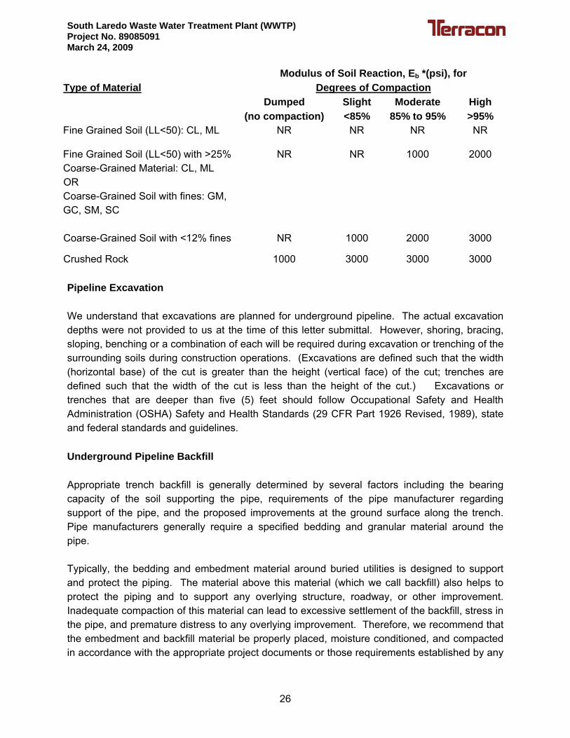
We understand that these structures will be supported on shallow foundation system. Loads of these structures were not provided at the time this report was prepared. A Vicinity Map, Bore Location Plan and individual boring logs are presented in Appendix A of this report. SITE EXPLORATION PROCEDURES Field Exploration Boring locations were chosen and staked on site by CDM. However, depth of the borings was decided based on the conversation between Terracon personnel, CDM and City of Laredo. Locations of the borings are shown on the attached “Bore Location Plan”. A total of 22 borings were drilled at this site. Borings corresponding to particular structures are shown below.
Structure/ Description Proposed Borings Proposed Depth (feet)
Headworks Facility B-1 30 Aeration Basins B-2, B-3, B-4 & B-5 40
B-6 & B-7 30 Secondary Clarifiers
B-8 40 Chlorine Contact Basins B-9 & B-10 40 Dewatering Building B-11 15 Chlorine Feed Building B-12 15 Septage Receiving Station B-13 15 Blower/Electrical Building B-14 15 5000 Linear Feet Pipeline Across The WWTP
B-15, B-16, B-17, B-18, B-19 & B-20
15
Entrance Road, Parking and Driveway Areas
B-21 5
Possible Detention Pond B-22 15 A truck-mounted, rotary drill rig equipped with continuous flight augers was used to advance the boreholes. Soil samples were obtained by the split-barrel sampling procedure. In this procedure, a standard 2-inch O.D. split-barrel sampling spoon is driven into the ground with a 140-pound hammer falling a distance of 30 inches. The number of blows required to advance the sampling spoon the last 12 inches of a normal 18-inch penetration is recorded as the standard penetration resistance value. These values are indicated on the borings logs at the depths of occurrence. The samples were sealed and transported to the laboratory for testing and classification.
2

South Laredo Waste Water Treatment Plant (WWTP) Project No. 89085091 March 24, 2009
Our field representative prepared the field logs as part of the drilling operations. The boring logs included visual classifications of the materials encountered during drilling and our field representative interpretation of the subsurface conditions between samples. Each boring log included with this report represents the engineer’s interpretation of the field logs and include modifications based on visual observations and testing of the samples in the laboratory. Laboratory Testing Selected samples retrieved from the borings were tested for moisture content and gradation to aid in the soil classification and to provide input for our analysis. Atterberg limits tests were also performed on selected portions of the subsurface soils to aid in classifying the soils, evaluate their plasticity and estimate their volume change potential with variations in moisture content. Laboratory Soil resistivity tests were also performed on selected sample of soils. The results of these laboratory tests are shown on the boring logs adjacent to the respective sample location. As part of the testing program, an engineer examined the soil samples in the laboratory. Based on the laboratory test results and the material’s texture and plasticity, the soil samples were described according to the attached General Notes and classified in accordance with the Unified Soil Classification System (USCS). The estimated group symbols for the USCS are shown in the appropriate column on the boring logs. A brief description of the USCS is presented in Appendix B of this report. Chemical Testing Laboratory soil resistivity tests, sulfate content tests and chloride content tests were conducted on selected soil samples recovered from the boring. The results of these tests are presented in table 1 of this report. SITE CONDITIONS Based on our visual observations and the provided plans, the sites for both the existing (Site 2) and the proposed (Site 1) water treatment plant is level and almost clear with partial areas covered with grass and trees. The site is located southeast of Laredo, Texas. SUBSURFACE CONDITIONS Soil Conditions Subsurface conditions were evaluated by drilling 22 borings within the planned limits of construction. In general, the soils encountered at this site consisted primarily of fine grained soils. The fine-grained soils generally consisted of LEAN CLAY (CL) and SILT (ML). The fine grained soils encountered at this site consist of light brown and brown in color and were soft to hard. Course grained soils were also encountered at this site and consisted of SAND (SP),
3

South Laredo Waste Water Treatment Plant (WWTP) Project No. 89085091 March 24, 2009
light brown. Some sand layers were also encountered within the fine grained soils. Please note that not all the materials were encountered in each boring. Also, the thicknesses of the materials will vary from one boring to the other. The subsurface soils encountered at the site generally appear adequate to support the proposed structures provided that the foundations are properly designed and constructed. Based on the result of the laboratory tests and our local experience, the fine grained LEAN CLAY (CL) and SILT (ML) materials are expected to have a potential for low volumetric changes (shrink/swell) due to fluctuations in their moisture content, whereas the coarse grained SAND (SP) materials are expected to be volumetrically stable with fluctuations in their moisture content. However due to low moisture content of the soils, some of the subgrade modification will be required and is addressed in the later sections of this report. Each boring log, representing the stratum descriptions, types of sampling used, laboratory test data and additional field data, is presented in Appendix A.
Groundwater Conditions Groundwater or subsurface water generally appears as either a permanent or temporary water source. Permanent subsurface water is generally present year round, which may or may not be influenced by seasonal and climatic changes. Temporary subsurface water is also referred to as a “perched” water source, which generally develops as a result of seasonal and climatic conditions. For the purposes of this report, we will simply refer to groundwater as subsurface water. The borings were drilled to their full depths using dry drilling techniques to aid in the observation of subsurface water. Subsurface water encountered in five of the soil borings during or upon completion of our field operations and is presented below.
Boring Number
Depth of Groundwater
(feet) B-2 38 B-3 27 B-4 38 B-5 28 B-8 39
Subsurface water maybe present after periods of wet weather. The borings were backfilled with soil cuttings after the drilling operations and subsurface water observations were completed. Specific information concerning subsurface water is noted on the boring logs presented in Appendix A of this report.
4

South Laredo Waste Water Treatment Plant (WWTP) Project No. 89085091 March 24, 2009
Piezometers. Borings B-3 and B-8 were converted to piezometers in order to monitor the subsurface water levels. Each piezometer was constructed using 2-inch diameter pipe. Slotted pipe was inserted into the open borehole and surrounded by sand to a depth of approximately 5 feet below the ground surface. Solid pipe with a surrounding bentonite seal was used in the upper 5 feet of the piezometer. The results of piezometer readings taken prior to issuing this report are presented in the table below.
GROUNDWATER LEVEL DATA
Date/Subsurface Water Depth (feet)
Piezometer 01/19/09 01/21/09 02/02/09 02/06/09 02/13/09 02/20/09
03/24/2009
B-3 27 26 25 25 25 25 27
B-8 39 39 39 39 39 39 37.5 Based on the subsurface water reading, it appears that the water at this site ranges between 25 and 39 feet below ground surface at this time. ENGINEERING RECOMMENDATIONS The foundation type being considered to provide support for the planned structures must satisfy several completely independent engineering criteria with respect to the subsurface conditions encountered at the site. One criterion is the foundation system must be designed with an appropriate factor of safety to reduce the possibility of a bearing capacity failure of the soils underlying the foundation when subjected to axial and lateral load conditions. The other criterion is movement of the foundation system due to compression (consolidation) or expansion (swell) of the underlying soils must be within tolerable limits for the structures. In addition to the criteria affecting the performance of the foundations, consideration must also be given to the effects of lateral earth pressures and hydrostatic pressures that may develop on the buried portion of the structures. Based on the soil data, various foundation systems can be used to support the anticipated plant structures. These foundations may consist of monolithic slabs-on-grade, shallow mats, spread footings and ring wall footings. Recommendations for these types of foundations are provided in this report. Regardless of the foundation type chosen, all piping leading to these structures should be designed with flexible connections to reduce potential damage due to differential movements between these structures and the piping. The suitability and performance of a soil supported foundation for a structure depends on many factors including the magnitude of soil movement expected, the type of structure, the intended use of the structure, the construction methods available to stabilize the soils, and our understanding of the owner’s expectations of the completed structure's performance. The
5

South Laredo Waste Water Treatment Plant (WWTP) Project No. 89085091 March 24, 2009
desired foundation systems may be used at this site provided the structure pads and foundations are designed and constructed as recommended in this report. Based on our laboratory test results, and using the Texas Department of Transportation (TxDOT) method Tex-124-E, we estimate that the Potential Vertical Rise (PVR) at this site is less than one (1) inch in its present condition. Foundation movements on the order of one (1) inch or less are generally considered to be within acceptable tolerances by local geotechnical and structural engineers for structures of this type. However, this movement does not take into account the movement criteria required or perceived by the owner. This “operational” performance criterion may be, and often are, more restrictive than the structural criteria or tolerances. Geotechnical Considerations Expansive soils were not encountered at this site. Based upon the results of our field and laboratory programs, we estimate that the soils at this site are somewhat volumetrically stable. Another geotechnical consideration is that very soft to stiff fine grain soils were encountered to a depth of approximately 20 feet. This material at its present condition has low moisture content. Subgrade modification required for the structure pads are discussed in following section of this report.
Pad Preparation.
• Strip vegetation, gravel, loose topsoil, and other deleterious material from the structure area. The structures area is defined as the structure footprint and any abutting flatwork including a 3-foot overbuild beyond the perimeter of these structures.
• Excavate 1 foot of on-site soil below the proposed structure pad elevation and
stockpile for later use. • Proofroll, overexcavate and replace soft yielding zones in the structure area as
described in the section of this report entitled “Earthwork”. • After proofrolling, scarify and moisture condition the top 6 inches of the exposed
subgrade soil between -2 and +3 percentage points of the optimum moisture content. Compact the subgrade to at least 95 percent of the maximum dry density determined in accordance with ASTM D 698.
• The structure pads can then be completed using onsite stockpiled material. The
stockpiled material should be placed in loose lifts not exceeding 8 inches and then be compacted lifts of about 6 inches in thickness. The stockpiled material
6

South Laredo Waste Water Treatment Plant (WWTP) Project No. 89085091 March 24, 2009
should be moisture conditioned between -2 and +3 percentage points of the optimum moisture content and then compacted to at least 95 percent of the maximum dry density determined in accordance with ASTM D 698. If the pad is raised above existing grades, select fill should then be used to achieve the desired finished pad elevation.
• To provide an “all-weather” working surface and to provide a more uniform slab
support, we recommend that the final 6 inches, or “cap”, of the structure pad consist of granular select fill or caliche material meeting the requirements given in the “Select Fill Materials” section of this report.
Slab Foundation Parameters commonly used to design this type of foundation are provided on Table 2 at the end of this text. The slab foundation design parameters presented on Table 2 are based on the criteria published by the Prestressed Concrete Institute (PCI), the Building Research Advisory Board (BRAB) and the Post-Tensioning Institute (PTI 3rd Edition). These are essentially empirical design methods and the recommended design parameters are based on our understanding of the proposed project, our interpretation of the information and data collected as a part of this study, our area experience, and the criteria published in the PCI, BRAB, and PTI design manuals. Several design methods use the modulus of subgrade reaction, k, to account for soil properties in design of flat, floor slabs. The modulus of subgrade reaction is a spring constant that depends on the kind of soil, the degree of compaction, and the moisture content. A k-value of about 100 pci can be used for design of a flat, grade-supported floor slab.
We recommend that the exterior perimeter grade beams be at least 24 inches below final structure grade. These recommendations are for proper development of bearing capacity for the continuous beam sections of the foundation system and to reduce the potential for water to migrate beneath the slab foundation. These recommendations are not based on structural considerations. Grade beam depths may need to be greater than recommended herein for structural considerations and should be properly evaluated and designed by the Structural Engineer. The grade beams or slab portions may be thickened and widened to serve as spread footings at concentrated load areas. For a slab foundation system designed and constructed as recommended in this report, post construction settlements should be less than 1 inch. Settlement response of a select fill supported slab is influenced more by the quality of construction than by soil-structure interaction. Therefore, it is essential that the recommendations for foundation construction be strictly followed during the construction phases of the building pad and foundation. All piping leading to the structures should be designed with flexible connections to reduce potential damage due to differential movements between the structures and the piping.
7

South Laredo Waste Water Treatment Plant (WWTP) Project No. 89085091 March 24, 2009
Construction Considerations. Grade beams for the slab foundations should preferably be neat excavated. The foundation pad should be prepared as recommended in “Pad Preparation” section of this report. Excavation should be accomplished with a smooth-mouthed bucket. If a toothed bucket is used, excavation with this bucket should be stopped 6 inches above final grade and the grade beam excavation completed with a smooth-mouthed bucket or by hand labor. Due to presence of low plasticity index Silt and Clay materials, caving of the foundation sidewalls may occur. Therefore, the foundation contractor should be prepared to use forms.
The foundation excavations should be sloped sufficiently to create internal sumps for runoff collection and removal of water. If surface runoff water or subsurface water seepage in excess of 1 inch accumulates at the bottom of the foundation excavation, it should be collected and removed and not allowed to adversely affect the quality of the bearing surface. Special care should be taken to protect the exposed soils from being disturbed or drying out prior to placement of the concrete or the select fill pad. Mat Foundation The mats should bear at least 2 feet below final structure grade and may be designed for a bearing pressure not to exceed 3,000 psf based on total load. The mat should be analyzed using a soil-structure interaction program to identify areas of high contact stresses, excessive movements and large moments. If a Winkler-type subgrade modulus model is utilized to model the mat response to load, a subgrade modulus (k) of 100 pounds per cubic inch (pci) can be utilized. Contact stresses should be distributed so that yield does not occur. The indicated bearing pressure includes a factor of safety against a bearing capacity failure of at least 3. A soil unit weight of 100 pounds per cubic foot (pcf) may be assumed for on-site or select fill soils placed above the mat, provided the fill is properly compacted. An allowable coefficient of friction across the mat foundation base of 0.75 can be used to aid in the resistance of ground line shear loading and includes an assumed factor of safety of at least 2. Post construction settlements for the mat foundation designed for the indicated contact pressure should be less than 1 inch, with differential settlements between the center and edge of the mat foundation on the order of ½ to ¾ of an inch assuming proper construction. If this degree of movement is not tolerable, the mat foundation may either be placed deeper, may be thickened to increase its stiffness or supported on drilled piers to reduce these post-construction movements. All piping leading to the structures should be designed with flexible connections to reduce potential damage due to differential movements between the structures and the piping.
Construction Considerations. Circular mat foundations should be neatly excavated. The foundation pad should be prepared as recommended in “Pad Preparation” section of this report. Excavation should be accomplished with a smooth-mouthed bucket. If a toothed bucket is used, excavation with this bucket should be stopped 6 inches above the final bearing surface
8

South Laredo Waste Water Treatment Plant (WWTP) Project No. 89085091 March 24, 2009
and the excavation completed with a smooth-mouthed bucket or by hand labor. If neat excavation is not possible then the foundation should be overexcavated and formed. All loose materials should be removed from the overexcavated areas and filled with lean concrete or compacted cement stabilized sand (two sacks cement to one cubic yard of sand) or flowable fill. Due to presence of low plasticity index Silt and Clay materials, caving of the foundation sidewalls may occur. Therefore, the foundation contractor should be prepared to use forms.
Steel and concrete for foundations should be placed the same day of excavation. If not, a seal slab consisting of lean concrete should be constructed on the same day the contractor achieves the final bearing level in order to protect the exposed foundation soils. The bearing surface should be excavated with a slight slope to create an internal sump for runoff water collection and removal. If surface runoff water accumulates at the bottom of the excavation, it should be pumped out prior to concrete placement. Under no circumstances should water be allowed to adversely affect the quality of the bearing surface. If the mat is buried, backfill above the foundations may be the excavated on-site soils or select fill soils. Backfill soils should be compacted to at least 95 percent of the maximum dry unit weight as determined by the standard moisture/density test (ASTM D 698) at moisture contents ranging from -2 to +3 percentage points of the optimum moisture content. The backfill should be placed in thin, loose lifts not to exceed 8 inches, with compacted thickness not to exceed 6 inches. Spread Footing Perimeter continuous or isolated spread footings should bear no shallower than 2 feet below the structure grade. The footings may be designed for a total load net bearing pressure of 3,000 psf, or a dead load net bearing pressure of 2,000 psf, whichever results in a larger bearing surface. These bearing pressures include factors of safety of approximately 2 and 3, respectively. Footings on different levels should be placed such that a downward 1(V):2(H) projection from the leading edge of the upper footing passes below the adjacent, deeper foundation unit. All footings should be located such that their edge-to-edge spacing is at least 25 percent of the width of the largest footing involved. If a closer footing spacing is necessary, we should be contacted to evaluate if the single footing capacity is still valid or if a reduction in the single footing capacity is necessary due to the close foundation spacing. The final footing layout should be reviewed by the Geotechnical Engineer. Settlements should be less than 1 inch for properly designed and installed footing foundations. Settlement of spread footings will be more sensitive to installation techniques than to soil-structure interaction. All piping leading to the structures should be designed with flexible connections to reduce potential damage due to differential movements between the structures and the piping.
9

South Laredo Waste Water Treatment Plant (WWTP) Project No. 89085091 March 24, 2009
Construction Considerations. Footing foundations should preferably be neat excavated. The foundation pad should be prepared as recommended in “Pad Preparation” section of this report. Excavation should be accomplished with a smooth-mouthed bucket. If a toothed bucket is used, excavation with this bucket should be stopped 6 inches above the final bearing surface and the excavation completed with a smooth-mouthed bucket or by hand labor. If neat excavation is not possible then the foundation should be overexcavated and formed. All loose materials should be removed from the overexcavated areas and filled with lean concrete or compacted cement stabilized sand (two sacks cement to one cubic yard of sand) or flowable fill. Due to presence of low plasticity index Silt and Clay materials, caving of the foundation sidewalls may occur. Therefore, the foundation contractor should be prepared to use forms.
Steel should be placed and the foundation poured the same day of excavation. If not, a seal slab consisting of lean concrete should be poured to protect the exposed foundation soils. The bearing surface should be excavated with a slight slope to create an internal sump for runoff water collection and removal. If surface runoff water in excess of 1 inch accumulates at the bottom of the excavation, it should be pumped out prior to concrete placement. Under no circumstances should water be allowed to adversely affect the quality of the bearing surface. If footings are buried, backfill above the foundation should be select fill soils. Backfill soils should be compacted to at least 98 percent of the maximum dry density as determined in accordance with ASTM D 698 at moisture contents ranging from -2 to +3 percentage points of the optimum moisture content. The backfill should be placed in loose lifts not exceeding 8 inches and then be compacted lifts of about 6 inches in thickness. Concrete Ringwall Foundation A ring foundation may be considered for the planned structures. Typically, the cross section of such a footing resembles an inverted “T”. The ringwall should bear at least 2 feet below structure grade and may be designed for a bearing pressure not to exceed 3,000 psf based on a total load. The indicated bearing pressures include a factor of safety against a bearing capacity failure of at least 3.
An allowable coefficient of friction across the ringwall foundation base of 0.75 can be used to aid in the resistance of ground line shear loading and includes an assumed factor of safety of at least 2. Total settlements, both immediate and long-term, should be less than 1 to 2 inches for a properly designed and constructed ringwall based on the indicated bearing pressure. Differential settlements of the ringwall foundation should be on the order of ½ to ¾ of an inch assuming proper construction. The indicated differential settlement was determined based on preparing the subgrade as noted previously in this report. Settlement response of ringwalls is impacted greatly by the quality of construction. Improper ringwall construction could result in differential settlements that are significantly greater than we have estimated. All piping leading
10

South Laredo Waste Water Treatment Plant (WWTP) Project No. 89085091 March 24, 2009
to the structures should be designed with flexible connections to reduce potential damage due to differential movements between the structures and the piping.
Construction Considerations. The ringwall foundation should preferably be neat excavated. The foundation pad should be prepared as recommended in “Pad Preparation” section of this report. If neat excavation is not possible then the foundation should be over excavated and formed. All loose materials should be removed from the over excavated areas which should then be filled with lean concrete or compacted cement stabilized sand (two sacks cement to one cubic yard of sand) or flowable fill. Due to presence of low plasticity index Silt and Clay materials, caving of the foundation sidewalls may occur. Therefore, the foundation contractor should be prepared to use forms. Steel should be placed and the foundation poured the same day of excavation. If not, a seal slab consisting of lean concrete should be poured to protect the exposed foundation bearing surface. The bearing surface should be excavated with a slight slope to create an internal sump for runoff water collection and removal. If surface runoff water in excess of 2 inches accumulates at the bottom of the excavation, it should be pumped out prior to concrete placement. Under no circumstances should water be allowed to adversely affect the quality of the bearing surface. Backfill above the ringwall should consist of select fill meeting the soil criteria presented later in this report. Backfill soils should be compacted to at least 98 percent of the maximum dry density determined in accordance with ASTM D 698 at moisture contents ranging between -2 and +3 percentage points of optimum moisture content. The backfill should be placed in loose lifts not exceeding 8 inches and then be compacted lifts of about 6 inches in thickness. Drilled Pier Foundations
Due to presence of sand and subsurface water at this site, underreamed piers can be proven difficult to construct at this site. Therefore, recommendations for only straight-sided (non-underreamed) piers are provided in the following paragraphs. Structure loads for this project may be supported on drilled straight-sided piers deeper no shallower than 15 feet. The drilled straight-sided piers should not extend deeper than 40 feet below existing grade without contacting us. The net allowable bearing pressures and side shear values per depth is presented in following table. These bearing pressures include factors of safety against a bearing capacity failure of approximately 2 for total load and 3 for dead load plus long-term live load, respectively. The allowable side shear values include an assumed factor of safety of at least 2. The adhesion factor for soils should be taken as 0 for the upper 4 feet of the shaft for compressive and uplift loading.
11

South Laredo Waste Water Treatment Plant (WWTP) Project No. 89085091 March 24, 2009
Allowable Bearing Pressure
Depth, feet
Allowable Side Shear (psf)
F.S. = 2
Based on Total Load (psf),
F.S. = 2
Based on Dead Load Plus Long-term Live Load
(psf), F.S. = 3
0 - 5 250 --- --- 5 – 10 300 --- ---
10 – 15 400 --- --- 15 – 20 700 9,000 6,000 20 – 25 1,000 11,250 7,500 25 – 30 1,200 13,500 9,000 30 – 35 1,500 18,000 12,000 35 – 40 2,000 20,000 13,000
The allowable end bearing and side shear values presented in this report are based on center-to-center spacing of the pier foundations no closer than a horizontal distance of 3 shaft diameters (using the larger bearing diameter). A closer spacing may be considered but may effect (reduce) the axial capacity of the foundation and/or change the design dimensions (foundation diameter and depth) depending on the spacing pattern of the foundations. Terracon can assist in evaluating the possibility of a closer spacing once a foundation layout has been determined. In addition to the axial compressive loads on the piers, these piers may be subjected to axial tension loads due to the induced structural loading conditions. This force can be used to compute the longitudinal reinforcing steel required in the pier to resist the uplift force induced. However, the cross-sectional area of the reinforcing steel should not be less than ½ percent of the gross cross-sectional area of the drilled pier shaft. The reinforcing steel should extend from the top to the bottom of the shaft to resist this potential uplift force. The ultimate uplift resistance of the straight-shaft drilled piers can be evaluated using the following equation:
Qr = 2 · d · Dp + Wp + PDL (for piers below 15 feet) Where: Qr = Ultimate uplift resistance of pier in kips (k) d = Diameter of pier shaft in feet (ft) Dp = Founding depth of pier minus the upper 10 feet of shaft in
contact with the soil in feet (ft) Wp = Weight of the drilled pier in kips (k) PDL = Dead Load acting on the drilled pier in kips (k)
12

South Laredo Waste Water Treatment Plant (WWTP) Project No. 89085091 March 24, 2009
We recommend that a factor of safety of at least 1.5 be applied to the computed ultimate uplift force. Total settlements, based on the indicated bearing pressures, should be less than 1 inch for properly designed and constructed straight-sided drilled piers. Settlement beneath individual piers will be primarily elastic with most of the settlement occurring during construction. Differential settlement may also occur between adjacent piers. The amount of differential settlement could approach 50 to 75 percent of the total pier settlement. For properly designed and constructed piers, differential settlement between adjacent piers is estimated to be less than ¾ of an inch. Settlement response of drilled piers is impacted more by the quality of construction than by soil-structure interaction. Improper pier installation could result in differential settlements that are significantly greater than we have estimated.
Foundation Installation. As mentioned in previous sections, subsurface water was encountered at a depth between 27 feet and 39 feet below existing grade during our subsurface operations. Based on the piezometer readings show that the water level can raise up to 25 feet below existing ground surface. Subsurface water levels are influenced by seasonal and climatic conditions, which result in fluctuations in subsurface water elevations. Additionally, it is common for water to be present after periods of significant rainfall. In addition the project is located within the 100 year flood plan. Therefore, the contractor should be prepared to use temporary casing to reduce the water flow into the excavation and/or sloughing of the excavation sidewalls should this occur. Prior to any excavation, the foundation contractor should verify the subsurface water levels. The casing and slurry methods for pier installation are discussed in the following paragraphs.
Casing Method. Casing will provide stability of the excavation walls but may not
completely eliminate subsurface water influx potential or stability of the pier excavation bottom unless the casing penetrates below any pervious soils. Casing that terminates in pervious soils may generate “boils” due to the head differential between the inside and outside of the casing and require that the casing be extended until the excess seepage or boils are eliminated. The actual casing depth should be chosen by the drilling subcontractor. If this operation is not successful or to the satisfaction of the engineer, the pier excavation should be flooded with fresh water to offset the differential water pressure caused by the unbalanced water levels inside and outside of the casing. When the pier excavation depth is achieved and the bearing area has been cleaned, steel and concrete should then be placed immediately in the excavation. If more than 6 inches of water is present in the excavation, water should be removed by pumping or the concrete should be tremied completely to the bottom of the excavation with a closed-end tremie.
Removal of casing should be performed with extreme care and under proper supervision to minimize mixing of the surrounding soil and water with the fresh concrete. Rapid withdrawal of casing or the auger may develop suction that could cause the soil to intrude into the excavation. An insufficient head of concrete in the casing during its withdrawal could also allow the soils to
13

South Laredo Waste Water Treatment Plant (WWTP) Project No. 89085091 March 24, 2009
intrude into the wet concrete. Both of these conditions may induce “necking”, a section of reduced diameter, in the pier.
Slurry Method. As an alternate to the use of casing to install the pier foundations, water
or a weighted drilling fluid may be considered. Slurry displacement drilling can only prevent sloughing and water influx but cannot control sloughing once it has occurred. Therefore, slurry displacement drilling techniques must begin at the ground surface, not after sloughing materials are encountered. Typical drilling fluids include those which contain polymers or bentonite. If a polymer is used with “hard” mixing water, a water softening agent may be required to achieve intimate mixing and the appropriate viscosity. The polymer manufacturer should be consulted concerning proper use of the polymer. If bentonite slurry is used, the bentonite should be mixed with water several hours before placing in the pier excavation. Prior mixing gives the bentonite sufficient time to hydrate properly. The drilling fluid should only be of sufficient viscosity to control sloughing of the excavation walls and subsurface water flow into the excavation. Care should be exercised while extracting the auger so that suction does not develop and cause disturbance or create “necking” in the excavation walls as described above. Casing should not be employed in conjunction with the slurry drilling technique due to possible trapping of loose soils and slurry between the concrete and natural soil. The use of weighted drilling fluid when installing drilled pier foundations requires extra effort to ensure an adequate bearing surface is obtained. A clean-out bucket should be used just prior to pier completion in order to remove any cuttings and loose soils which may have accumulated in the bottom of the excavation. Steel and concrete should be placed in the excavation immediately after pier completion. A closed-end tremie should be used to place the concrete completely to the bottom of the excavation in a controlled manner to effectively displace the slurry during concrete placement. When the pier excavation depth is achieved and the bearing area has been cleaned, steel and concrete should then be placed immediately in the excavation. The concrete should be placed completely to the bottom of the excavation with a closed-end tremie in the pier excavation if more than 3 inches of water is ponded on the bearing surface or the slurry drilling technique is used. A short tremie may be used if the excavation has less than 3 inches of ponded water or if the water is pumped out prior to concrete placement. The fluid concrete should not be allowed to strike the pier reinforcement, temporary casing (if required) or excavation sidewalls during concrete placement. The reinforcing steel and concrete should be placed in the excavations immediately following drilling and evaluation for proper bearing stratum, embedment, and cleanliness. Under no circumstances should the foundation excavations remain open overnight. All aspects of concrete design and placement should comply with the American Concrete Institute (ACI) 318-99 Code Building Code Requirements for Structural Concrete, ACI 336.1-98 entitled Standard Specification for the Construction of Drilled Piers, and ACI 336.3R-93 entitled Suggested
14

South Laredo Waste Water Treatment Plant (WWTP) Project No. 89085091 March 24, 2009
Design and Construction Procedures for Pier Foundations. Concrete should be designed to achieve the specified 28-day strength when placed at a 7 inch slump with a ±1 inch tolerance. Adding water to a mix that has been designed for a lower slump does not meet the intent of this recommendation. If a high range water reducer is used to achieve this slump, the span of slump retention for the specific admixture under consideration should be thoroughly investigated. Compatibility with other concrete admixtures should also be considered. A technical representative of the admixture supplier should be consulted on these matters. Successful installation of drilled piers is a coordinated effort involving the general contractor, design consultants, subcontractors and suppliers. Each must be properly equipped and prepared to provide their services in a timely fashion. Several key items of major concern are:
• Proper drilling rig with proper equipment (including casing, augers and rock bits/core barrels). High torque (rock drilling) equipment will be required;
• Reinforcing steel cages tied to meet project specifications;
• Proper scheduling and ordering of concrete for the piers; and
• Monitoring of installation by design professionals.
Pier construction should be carefully monitored to assure compliance of construction activities with the appropriate specifications. Particular attention to the referenced publication is warranted for pier installation. A number of items of concern for pier installation include those listed below.
• Pier locations • Vertical alignment • Competent bearing • Steel placement
• Concrete properties and placement • Casing removal (if required) • Proper casing seal for subsurface water control • Slurry viscosity (if required)
If the contractor has to deviate from the recommended foundations, Terracon should be notified immediately so additional engineering recommendations can be provided for appropriate foundation types. Below-Grade Walls We understand that several structures will be constructed below grade. Below-grade walls will need to be designed for the lateral earth pressures that will be exerted by the fill being retained beneath the floor slab. We assume that these members will need to be designed for little to no outward movement. As a result, we have considered “at rest” earth pressure conditions for computations of the equivalent fluid density. The following equivalent fluid densities can be used to evaluate the lateral “at-rest” earth pressures acting on the exterior members.
15

South Laredo Waste Water Treatment Plant (WWTP) Project No. 89085091 March 24, 2009
Backfill Material Type “At-Rest” Condition Equivalent Fluid Density, pcf
Imported, Granular, Free Draining Gravel 54
Imported, Granular, Free Draining Sand 60
Crushed Limestone or Caliche Base 65
On-site Soil 80 A passive earth fluid density of 125 pcf may be used to calculate the passive earth pressure. The above passive value includes a factor of safety of two (2). The equivalent fluid densities do not include provisions for either surcharge on top of the wall, hydrostatic forces or wall backfill or for sloping backfill. The gravel backfill should comply with the gradation, plasticity and compaction criteria contained in ASTM C-33, Size 67 or Size 467. This material will ensure that the backfill is free draining and that the installed drainage system is allowed to perform its function. The sand used for backfill should be a free draining material with 100 percent passing the No 16 sieve and not more than eight (8) percent passing the No 200 sieve. The gravel used for backfill should also be a free draining material that is a washed, evenly graded mixture of crushed stone, or crushed or uncrushed gravel with 100 percent passing the one and one-half (1½) inch sieve and not more than five (5) percent passing the No 4 sieve.
Hydrostatic Pressure. It is possible that hydrostatic pressures may be generated on the bottom of the structures, especially on the deeper structures. This pressure will tend to force the structures up (float) out of the ground, unless measures are taken to prevent this from occurring. The structures designer must take this into account or it may cause problems during construction and in the future. We recommend that a factor of safety of at least 2 be used against uplift due to hydrostatic pressure. Any structure founded below 20 feet should be designed to withstand the buoyant forces. Uplift on the structures may be resisted by both the weight of the structure itself and the weight of the backfill placed over the foundation of the structure. For the purposes of uplift calculations, the weight used for the structure should be the empty weight since this would represent a more conservative condition during operation of the structures. The weight of the soil or flowable backfill above these flanges can be used, in addition to the weight of the empty structures, to resist the potential hydrostatic uplift forces. When performing weight calculations, densities of 110 pcf should be used for the on-site backfill. Below the water level, effective (soil density minus the unit weight of water) unit densities should be used. If a drain is installed below the mat foundations, the hydrostatic forces should not be a factor to consider in design.
16

South Laredo Waste Water Treatment Plant (WWTP) Project No. 89085091 March 24, 2009
Seismic Design Criteria The 2006 International Building Code (IBC) requires certain geotechnical seismic design criteria to aid the Structural Engineer in their analysis to develop a design response of the building to earthquake loading. These criteria include site spectral acceleration values and the seismic site class. The criteria pertaining to this are:
• Site Class D • Maximum Considered Earthquake 0.2 second Spectral Acceleration (SS) of 0.07g • Maximum Considered Earthquake 1.0 second Spectral Acceleration (S1) of 0.02g
The site class definition was determined using SPT N-values and laboratory shear strength tests in conjunction with Table 1613.5.2 in the 2006 IBC. The Spectral Acceleration values were determined using publicly available information provided on the United States Geological Survey (USGS) website. The above criteria can be used to determine the Seismic Design Category using Tables 1613.5.6 (1) and 1613.5.6 (2) in the 2006 IBC.
Presence of Potential Corrosive Conditions. Corrosivity testing of the soil was performed as a part of our testing program. Based on the lab results, the Sulfate levels range between 238 and 1,140 ppm (parts per million). Based on Table 4.3.1 from the ACI BUILDING CODE the Sulfate exposure is moderate, however due to the level of sulfate type II cement should be used. Based on the lab results, the Chloride levels range between <10 and 207 ppm (parts per million). Therefore corrosion protection methods for the steel are not required. Pavements Entrance road, parking areas and driveway areas are planned of this project. Gravel/ Prime Coat pavement, Flexible pavement and rigid concrete pavement systems may be considered for the project for “Light” and “Heavy” traffic loading conditions. For this project “Light” refers to general parking areas and automobile traffic areas, and “Heavy” refers to service area drives, maintenance vehicles and main access drives. We understand that the “Gravel/Prime Coat Pavement” will consist of a prepared subgrade, base material, gravel, and a sealant of prime coat. The flexible and rigid concrete pavement will consist of a prepared subgrade, base material, and asphalt or concrete. We can revise our pavement recommendations if different traffic information is provided to us. Gravel/Prime Coat Pavement Due to the wheel loads imposed by the heavier vehicles, the access drive should be designed to accommodate occasional vehicles even though the traffic from such will be limited. If the pavement is anticipated to be exposed to frequent heavy traffic, we should be provided with the anticipated traffic loads so that we can provide an appropriate pavement section. One of the following pavement design options may be considered based on economics and expected
17

South Laredo Waste Water Treatment Plant (WWTP) Project No. 89085091 March 24, 2009
performance. The following options are listed from lowest to highest in performance expectancy. Please note that the performance of the below pavement options will also be dependent upon the amount and type of traffic that travels the pavement.
Option 1 – Granular base material overlying a properly prepared subgrade. This option will be more prone to the effects of wet weather than the other options listed below. Thus, more distress such as potholes and “wash-boards” should be expected. Of the three options, this option will likely require more frequent maintenance.
Option 2 – Granular base material overlying a properly prepared subgrade and sealed with a prime coat for partial waterproofing. This option will also be prone to effects of wet weather. However, the prime coat may aid in delaying the development of potholes and “wash-boards”. This option will likely require less maintenance than the above Option 1. Reapplication of the prime coat should be planned as part of the maintenance program.
Option 3 – Granular base material overlying a properly prepared subgrade and sealed with a prime coat followed by placement of one or two thin, clean courses of aggregate; also known as a single or double course “all weather” wearing surface treatment. This option includes the construction of an “all weather” wearing surface, and therefore, will be less prone to damage from wet weather than the other two options and will require less maintenance accordingly. Reapplication of the wearing surface should be included as part of the maintenance program to aid in prolonging the life of the section.
The thickness of the roadway base section should be at least 10 inches. The performance and life of the roadway section will depend on proper preparation of the subgrade underlying the base material; proper selection, quality, and placement of the base material; and selection of one of the three roadway design options. Recommendations for subgrade preparation and selection and placement of fill materials to be used for the roadway sections presented in “Pavement Section Materials” of this report.
It is important that positive drainage be provided. If a surface treatment is not applied to the roadway surface, the roadway should be clearly marked so vehicles do not veer off the road alignment, thus causing rutting of the switching station pad surface. Flexible and Rigid Pavement System Boring B-21 was drilled in the proposed pavement areas. The pavement subgrade is expected to consist of cohesive SILT with some sand. We estimate a California Bearing Ratio (CBR) value of about 2 to 3 percent for design of flexible pavement sections constructed on subgrade
18

South Laredo Waste Water Treatment Plant (WWTP) Project No. 89085091 March 24, 2009
prepared as recommended in the “Earthwork” section of this report. A modulus of subgrade reaction (k) value of about 100 pci is estimated for design of portland cement rigid concrete pavement sections. The recommended pavement sections for flexible and rigid pavements for light and heavy traffic conditions are provided in the subsequent tables.
Flexible Pavement System.
Material Thickness, inches
Modified Subgrade or Geogrid
Moisture Conditioned Subgrade
Component Light Heavy Light HeavyHot Mix Asphaltic Concrete Granular Base Material Modified Subgrade or Geogrid Moisture Conditioned Subgrade
2.0 6.0 6.0 ---
2.0 10.0 6.0 ---
2.0 9.0 --- 6.0
2.0 13.0 --- 6.0
Rigid Pavement System.
Material Thickness, inches
Modified Subgrade
Moisture Conditioned Subgrade
Component Light Heavy Light HeavyReinforced Concrete Modified Subgrade Moisture Conditioned Subgrade
5.0 6.0 ---
6.0 6.0 ---
5.5 --- 6.0
6.5 --- 6.0
• A geogrid placed at the interface of the subgrade and base material may be used
as a replacement for a modified subgrade for asphalt pavement. The geogrid should meet the criteria given in Table 3. Tensar BX 1100 meets these criteria.
• Asphaltic base material may be used in place of granular, unbound base
material. Every 2 inches of granular base material may be replaced with 1 inch of asphaltic base material. However, the minimum thickness of the asphaltic base material is 4 inches and the minimum thickness of the granular base material is 6 inches.
Proper perimeter drainage is very important and should be provided so infiltration of surface water from unpaved areas surrounding the pavement is minimized. We do not recommend installation of landscape beds or islands in the pavement areas. Such features provide an avenue for water to enter into the pavement section and underlying soil subgrade. Water penetration usually results in degradation of the pavement section with time as vehicular traffic
19

South Laredo Waste Water Treatment Plant (WWTP) Project No. 89085091 March 24, 2009
traverses the affected area. Above grade planter boxes, with drainage discharge onto the top of the pavement or directed into sewers, should be considered if landscape features are desired. Treated base material should be considered in asphalt pavement areas near landscape islands/beds or where drainage may be of concern. A crack sealant compatible to both asphalt and concrete should be provided at all concrete-asphalt interfaces. If curbs are needed in certain areas for asphalt and concrete pavements, they should extend below the base material at least 3 inches into the clay subgrade. This will help reduce migration of subsurface water into the pavement base course from adjacent areas. Also to help reduce the migration of subsurface water into the pavement base course, we recommend that backfill behind the curbs consist of low permeability compacted clay soils not loose topsoil, sand, and/or mulch. Strip (wick) drains installed behind the curbs will also help protect the pavements from water which ponds behind the curbs. A crack sealant compatible to both asphalt and concrete should be provided at all concrete-asphalt interfaces. A rigid pavement section constructed of reinforced concrete should be used in areas that will be subjected to heavy wheel and traffic volumes, such as waste bin or “dumpster” areas, entrance/exit ramps, drive lanes and delivery areas. The concrete pavement areas should be large enough to properly accommodate the vehicular traffic and loads. For example:
• the dumpster pad should be large enough so the wheels of the collection truck are entirely supported on the concrete pavement during lifting of the waste bin; and
• the concrete pavement should extend beyond any areas that require extensive
turning, stopping, and maneuvering.
The pavement design engineer should consider these and other similar situations when planning and designing pavement areas. Waste bin and other areas that are not designed to accommodate these situations often result in localized pavement failures. The pavement sections have been designed using generally recognized structural coefficients for the pavement materials. These structural coefficients reflect the relative strength of the pavement materials and their contribution to the structural integrity of the pavement. If the pavement does not drain properly, it is likely that ponded water will infiltrate the pavement materials resulting in a weakening of the materials. As a result, the structural coefficients of the pavement materials will be reduced and the life and performance of the pavement will be shortened. The Asphalt Institute recommends a minimum of 2 percent slope for asphalt pavements. The importance of proper drainage cannot be overemphasized and should be thoroughly considered by the project team.
Pavement Section Materials. Presented below are selection and preparation guidelines for various materials that may be used to construct the pavement sections. Submittals should be made for each pavement material. The submittals should be reviewed by
20

South Laredo Waste Water Treatment Plant (WWTP) Project No. 89085091 March 24, 2009
the Geotechnical Engineer and appropriate members of the design team, and should provide test information necessary to verify full compliance with the recommended or specified material properties.
Hot Mix Asphaltic Concrete Surface Course - The asphaltic concrete surface course should be plant mixed, hot laid Type C or D Surface meeting the master specifications requirements of 2004 TxDOT Standard Specifications Item 340 and specific criteria for the job mix formula. The mix should be designed for a stability of at least 40 and should be compacted between 91 and 95 percent of the maximum theoretical density as measured by TEX-227-F. The asphalt cement content by percent of total mixture weight should fall within a tolerance of ±0.3 percent asphalt cement from the specific mix. In addition, the mix should be designed so 75 to 85 percent of the voids in the mineral aggregate (VMA) are filled with asphalt cement. The grade of the asphalt cement should be PG 64-22. Aggregates known to be prone to stripping should not be used in the hot mix. If such aggregates are used measures should be taken to mitigate this concern. The mix should have at least 70 percent strength retention when tested in accordance with Tex-531-C.
Pavement specimens, which shall be either cores or sections of asphaltic pavement, will be tested according to Test Method TEX-207-F. The nuclear-density gauge or other methods which correlate satisfactorily with results obtained from project pavement specimens may be used when approved by the Engineer. Unless otherwise shown on the plans, the Contractor shall be responsible for obtaining the required pavement specimens at their expense and in a manner and at locations selected by the Engineer. Concrete - Concrete should have a minimum 28-day design compressive strength of 4,000 psi. Prime Coat - The prime coat should consist of sealing the base with a prime oil such as an MC-30 or an emulsion. The prime coat should be applied at a rate of about 0.2 to 0.5 gallons per square yard with materials which meet TxDOT 2004 Standard Specifications Item 300. The prime coat will help to minimize penetration of rainfall and other moisture which penetrates the base. However, due to weathering and traffic, treatment will probably be necessary on a periodic basis to protect the base. In addition, isolated areas of the base which have developed pot holes or other distress may need to be removed and replaced prior to application of a prime coat for maintenance. The prime coat without additional surface treatment may not be very effective when using non-treated base material.
21

South Laredo Waste Water Treatment Plant (WWTP) Project No. 89085091 March 24, 2009
Surface Treatment - The surface treatment would consist of applying a prime coat as described above, followed by an application of asphalt cement immediately followed by an application of aggregate rolled into the surface. After the first course has been placed, another application of asphalt cement and aggregate may be applied over the first course, if desired. The asphalt cement should be the equivalent of an AC-20 (PG 64-22). The aggregate should meet the gradation requirements of a Grade 3 aggregate for the first course and a Grade 5 for the second course. If a two-course treatment is performed, the smaller aggregate should generally fit between the voids in the larger aggregate. If only one course is utilized, a Grade 4 or 5 aggregate is recommended. Application rates of the AC-20 and aggregate should be determined in accordance with the Texas Design Method, Asphalt Institute Manual Series MS 13, or proven field experience with locally available materials. All materials and construction procedures should comply with the applicable Items of the 2004 TxDOT Standard Specifications. Granular Base Material - Base material may be composed of crushed limestone base meeting all of the requirements of 2004 TxDOT Item 247, Type A, Grade 1 or 2; and should have no more than 15 percent of the material passing the No. 200 sieve. The base should be compacted to at least 95 percent of the maximum dry density as determined by the modified moisture-density relation (ASTM D 1557) at moisture contents ranging between -2 and +3 percentage points of the optimum moisture content. As an alternate to the Type A base, “caliche” material meeting the requirement of Table 4 may be used. The base should be compacted to at least 95 percent of the maximum dry density determined in accordance with the modified moisture-density relation (ASTM D 1557) at moisture contents ranging between minus (-2) and plus three (+3) percentage points of optimum. A geogrid may be used to reduce the thickness of the granular base material. The thickness of this layer may be reduced to 70 percent (a 30 percent reduction) of the thickness listed above with the installation of the geogrid at the interface of base and subgrade. The geogrid should meet the criteria given in Table 3. Regardless, the thickness of the base material should be at least six (6) inches. Asphaltic Base Course - The asphaltic base material should meet the specification requirements of 2004 TxDOT Standard Specification Item 340, Type A or B or Item 292, Grade 1. Natural Subgrade - We recommend that the site be stripped of loose topsoil, vegetation and then proofrolled with a 15-ton roller or equivalent machinery to evidence any soft or weak areas. If such areas are found to exist, they should be excavated and replaced under controlled (compacted) conditions as described in
22
South Laredo Waste Water Treatment Plant (WWTP) Project No. 89085091 March 24, 2009
the “Earthwork” section of this report. The excavated material can be used to restore the ground surface to original grade or an imported fill may be considered as an alternate source. When stripping and proofrolling activities are completed, the subgrade should be scarified to a depth of 6 inches and moisture conditioned between -2 and +3 percentage points of the optimum moisture content. The scarified subgrade should be compacted to at least 95 percent of the maximum dry density as determined by the standard moisture/density test (ASTM D 698). Modified Subgrade - Soil Modification or treatment to the subgrade will improve its strength and load carrying capacity. The subgrade may be treated with cement in accordance with TxDOT Item 275. If used, the quantity of cement required should be determined at the laboratory to meet the minimum required compressive strength of 300 psi at 7 days. Subgrade should be compacted to at least 95 percent of the maximum dry density determined in accordance with ASTM D 698 at moisture contents ranging from -2 to +3 percentage points of the optimum moisture content. In areas where concrete will be placed above the cement treated subgrade we suggest that the subgrade be traversed several times with a pneumatic roller to induce "micro-cracks". This technique will help reduce the chances for soil-cement crack patterns to subsequently reflect/propagate through the overlying wearing surface. Moisture Conditioned Subgrade - The subgrade should be scarified to a depth of 6 inches and moisture conditioned between -2 and +3 percentage points of the optimum moisture content. The subgrade should then be compacted to at least 95 percent of the maximum dry density determined in accordance with ASTM D 698.
Details regarding subgrade preparation and fill placement and compaction are presented in the subsection titled “Earthwork.”
Pavement Joints and Reinforcement. The following is recommended for all concrete pavement sections in this report. Refer to ACI 330 “Guide for Design and Construction of Concrete Parking Lots” for additional information. Contraction Joint Spacing: Contraction joints should be spaced 12½ feet each way for
pavement thickness of 5 or 5½ inches; 15 feet each way for pavement thickness of 6 inches or greater.
Contraction Joint Depth: At least ¼ of pavement thickness. Contraction Joint Width: One-fourth inch or as required by joint sealant
manufacturer.
23

South Laredo Waste Water Treatment Plant (WWTP) Project No. 89085091 March 24, 2009
Construction Joint Spacing: To attempt to limit the quantity of joints in the pavement, consideration can be given to installing construction joints at contraction joint locations, where it is applicable.
Construction Joint Depth/ Width: Full depth of pavement thickness. Construct sealant
reservoir along one edge of the joint. Width of reservoir to be ¼ inch or as required by joint sealant manufacturer. Depth of reservoir to be at least ¼ of pavement thickness.
Isolation Joint Spacing: As required to isolate pavement from structures, etc. Isolation Joint Depth: Full depth of pavement thickness. Isolation Joint Width: One-half to 1 inch or as required by the joint sealant
manufacturer. Expansion Joint: None (see note below)
Note: In this locale, drying shrinkage of concrete typically significantly exceeds anticipated
expansion due to thermal affects. As a result, the need for expansion joints is eliminated provided all joints (including saw-cuts) are sealed. Construction of an unnecessary joint may be also become a maintenance problem. All joints should be sealed. If all joints, including saw-cuts, are not sealed then expansion joints should be installed.
Distributed Steel: Steel reinforcement may consist of steel bars described as follows:
No 3 reinforcing steel bars at 12 inches on center each way, Grade 60; or No 4 reinforcing steel bars at 18 inches on center each way, Grade 60
Note: It is imperative that the distributed steel be positioned accurately in the pavement
cross section. All construction joints have dowels. Dowel information varies with pavement thickness as presented as follows.
Pavement Thickness: 5, 5½ inches 6, 6½ inches Dowels: ⅝ inch diameter ¾ inch diameter Dowel Spacing 12 inches on center 12 inches on center Dowel Length: 12 inches long 14 inches long Dowel Embedment: 5 inches 6 inches
24

South Laredo Waste Water Treatment Plant (WWTP) Project No. 89085091 March 24, 2009
Details regarding subgrade preparation and fill placement and compaction are presented in the following subsection. Underground Pipeline Design Recommendations
Trench Bearing Pressures. A 5,000 linear feet pipeline is planned across this project site. The pipe is expected to bear about 5 to 10 feet below the existing ground surface. A total of six borings B-15 through B-20 to a depth of 15 feet were drilled along the pipeline alignment. Cohesive materials, consisted of Silt and Lean Clay were encountered along the pipeline alignment. The subsurface soils have sufficient bearing capacity to support the sewer pipe. Accordingly, we recommend a net allowable bearing pressure of 2,000 pounds per square foot (psf). This bearing pressure includes a factor of safety of at least 2. The bearing pressure also assumes that the bearing surface will be free and clean of any soft or moist material and loose debris, and the pipe will be bedded on a gravel layer.
Buoyant Uplift. Subsurface water was not encountered in the borings during field
operations. However it is possible for water to be present after significant amount of rainfall. Accordingly, underground pipes or structures should be designed to withstand potential buoyant uplift groundwater forces.
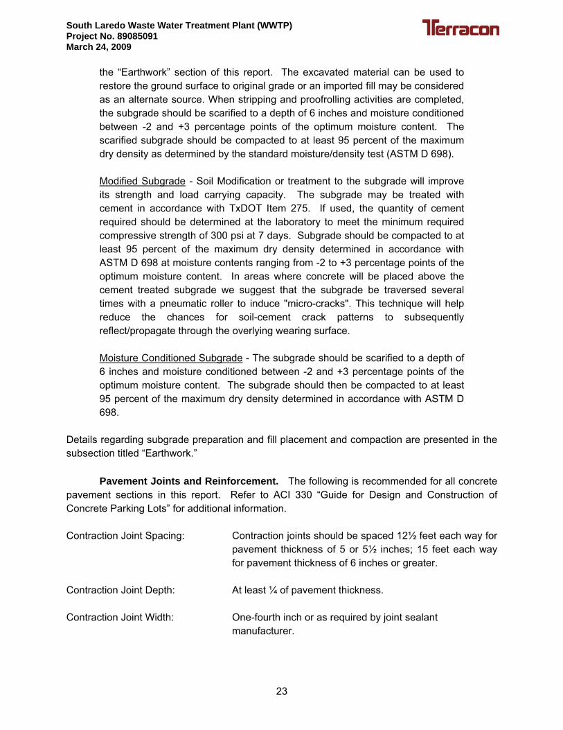
Modulus of Soil Reaction. A modulus of soil reaction for the in-situ soil, Es or En, of 400 to 1,500 psi may be used in the design of the pipe. Additionally, the modulus of soil reaction, Eb or sometimes referred to as E’, of the backfill material supporting the sides of the pipe is also used in the design of the flexible piping. This value is a function of several variables that include:
• Soil type that comprises the backfill material supporting the pipe sides. • Degree of compaction of the backfill material supporting the pipe sides. • Lift thickness of the backfill material supporting the pipe sides.
Values for Eb vary, depending on the pipe backfill and bedding materials. Fine-grained soils consisting of primarily clay and silt should not be used for bedding materials and backfill around the pipe. More specific information regarding this design parameter is included in ASTM D2321 entitled “Standard Practice for Underground Installation of Thermoplastic Pipe for Sewers and Other Gravity Flow Applications.” Below is a table of typical modulus of soil reaction values, Eb, for various backfill materials at different compaction ranges.
25
South Laredo Waste Water Treatment Plant (WWTP) Project No. 89085091 March 24, 2009
Type of Material
Modulus of Soil Reaction, Eb *(psi), for Degrees of Compaction
Dumped (no compaction)
Slight <85%
Moderate 85% to 95%
High >95%
Fine Grained Soil (LL<50): CL, ML NR NR NR NR
Fine Grained Soil (LL<50) with >25% Coarse-Grained Material: CL, ML OR Coarse-Grained Soil with fines: GM, GC, SM, SC
NR NR 1000 2000
Coarse-Grained Soil with <12% fines NR 1000 2000 3000
Crushed Rock 1000 3000 3000 3000 Pipeline Excavation We understand that excavations are planned for underground pipeline. The actual excavation depths were not provided to us at the time of this letter submittal. However, shoring, bracing, sloping, benching or a combination of each will be required during excavation or trenching of the surrounding soils during construction operations. (Excavations are defined such that the width (horizontal base) of the cut is greater than the height (vertical face) of the cut; trenches are defined such that the width of the cut is less than the height of the cut.) Excavations or trenches that are deeper than five (5) feet should follow Occupational Safety and Health Administration (OSHA) Safety and Health Standards (29 CFR Part 1926 Revised, 1989), state and federal standards and guidelines. Underground Pipeline Backfill Appropriate trench backfill is generally determined by several factors including the bearing capacity of the soil supporting the pipe, requirements of the pipe manufacturer regarding support of the pipe, and the proposed improvements at the ground surface along the trench. Pipe manufacturers generally require a specified bedding and granular material around the pipe. Typically, the bedding and embedment material around buried utilities is designed to support and protect the piping. The material above this material (which we call backfill) also helps to protect the piping and to support any overlying structure, roadway, or other improvement. Inadequate compaction of this material can lead to excessive settlement of the backfill, stress in the pipe, and premature distress to any overlying improvement. Therefore, we recommend that the embedment and backfill material be properly placed, moisture conditioned, and compacted in accordance with the appropriate project documents or those requirements established by any
26

South Laredo Waste Water Treatment Plant (WWTP) Project No. 89085091 March 24, 2009
applicable city or county standard specifications for public works construction. The bedding material should meet the following gradation.
Gravel Bedding Specifications
Percent Passing 1½ Inch Sieve 100 Percent Passing 1 Inch Sieve 90 to 100 Percent Passing 3/8 Inch Sieve 25 to 60 Percent Passing No. 4 Sieve 0 to 10 Percent Passing No. 8 Sieve 0 to 5
Backfill beneath roadways should attempt to match the soil type exposed in the excavation sidewalls. As a compaction guideline, we recommend that all trench backfill be placed in loose lifts not to exceed 8 inches, moisture conditioned between -2 and plus +3 percentage points of the optimum moisture content, and compacted to at least 95 percent of the maximum dry density as evaluated by ASTM D 698. Trench backfill in non roadway areas should be placed in loose lifts not to exceed 8 inches, moisture conditioned between -2 and plus +3 percentage points of the optimum moisture content, and compacted to at least 90 percent of the maximum dry density as evaluated by ASTM D 698. Recommended compaction efforts are as per the City of Laredo specification. However, contractor should check the most recent City of Laredo’s specification for the compaction efforts. Flowable fill can be used as an alternative to soil backfill, particularly beneath roadways. Flowable fill typically consists of a mixture of sand, portland cement, fly ash, and water and is readily available from ready-mixed concrete suppliers. This very low strength cementitious fill is placed in a slurry form and readily takes the shape of the excavation. Properly designed and placed, it can be trenched through by a backhoe for future repairs or modifications as required. Embedment backfill along the sides to the top of the pipe and possibly 12 to 24 inches above the pipe should consist of materials that are acceptable to the project civil engineer or materials meeting those requirements established by any applicable city or county standard specifications for public works construction. To avoid potential damage to the pipe, the embedment material should not contain materials exceeding 3 inches in maximum dimension. Onsite soils should be suitable as backfill above the embedment material provided that the soils do not contain deleterious material or particles exceeding 4 inches in maximum dimension. However, we recommend gravel backfill for this zone, since it will not require compaction or moisture conditioning, thus no stress on the pipe during construction. Construction equipment with wheel or gross loads exceeding the pipe’s design strength should not be driven over or close to the pipeline. Additional cover placed on top of the pipe or an alternate route should be provided for machinery producing excessive loads.
27

South Laredo Waste Water Treatment Plant (WWTP) Project No. 89085091 March 24, 2009
Percolation Tests The purpose of this study is to evaluate the soils as per the On Site Sewage Facility (OSSF) requirements. PT-1 boring was advanced to about 5 feet at the site as shown in Figure 2. Percolation tests were performed at the locations of boring PT-1. Subsurface water was not encountered within the explored depth of 5 feet either during or after completion of field activities. Soil percolation tests are used to determine the ability of a soil to transmit wastewater effluent through the soil profile. The soil percolation rate is the amount of time water takes to move through soil, measured in minutes per inch. Finer textured soils (Type IV Clay) have slower percolation rates; it takes longer for water to drain from a test hole. These soil types need larger drainfields than soils with faster percolation rates, such as sandy soils, to handle a given amount of wastewater. Based on the performed percolation tests, the percolation test result was 3 Minute per Inch (MPI) as shown in the Table 5. Earthwork The comments and suggestions in this section are provided for planning and informational purposes so project specifications can be prepared and to indicate conventional methods to achieve the intent of our design recommendations. Details regarding excavation, dewatering, selection of equipment/machinery, trafficability, project site safety, shoring, and other similar construction techniques that require “means and methods” to accomplish the work is the sole responsibility of the project contractor. It should be recognized that the comments contained in this report are based on the observations of small diameter boreholes and the performance of larger excavations may differ significantly as a result of the differences in excavation sizes. Construction means and methods selected by the contractor may differ from those described in this report. Any variations may significantly impact the anticipated behavior of the subsurface conditions during the construction process.
Site Access. Proper site drainage should be maintained during the entire construction
phase so ponding of surface runoff does not occur and cause construction delays and/or inhibit site access, particularly in cut areas. During construction, it is possible the surficial clay soils may become excessively wet as a result of inclement weather conditions. When the moisture content of these clay soils elevates above what is considered to be the optimum range of moisture for compaction operations, they can become difficult to handle and compact. If such conditions create a hindrance to compaction operations or site access, portland cement may be mixed with these soils to improve their workability. The modifier can be mixed in general accordance with TxDOT Items 260 and 275. However, the purpose of the modifier is to dry out the subgrade and allow site workability. The strict requirements for curing and the actual modifier percentage can and should be at the discretion of the contractor. The modified subgrade, however, should be compacted to at least 95 percent of the maximum dry density as
28

South Laredo Waste Water Treatment Plant (WWTP) Project No. 89085091 March 24, 2009
evaluated by ASTM D 698 at moisture contents between -2 to +3 percentage points of the optimum moisture content.
Structure Pad and Pavement Subgrade Preparation. The structure pad and pavement areas should be stripped of all loose debris or topsoil, any organics, and other deleterious materials. Subgrade preparation should extend at least three (3) feet beyond the horizontal limits of the pavements and pads (including all abutting sidewalks and other flatwork). Structure pad should be excavated 1 foot After site stripping and excavating operations, the exposed subgrade should be proofrolled with appropriate construction equipment weighing at least 20 tons. The purpose of this recommendation is to check the subgrade for weak/soft zones prior to fill or base placement and compaction. This operation should be observed and evaluated by qualified geotechnical personnel experienced in earthwork operations. If weak or soft zones are evidenced during proofrolling operations, the weak material in the subject area should be removed to expose competent subgrade soils in both the horizontal and vertical limits. The excavated soil can be reused to restore grade at these isolated areas provided that the material is free and clean of any organic and other deleterious debris. The reused soil should be placed in 6 inch compacted lifts that are moisture conditioned to between -2 and +3 percentage points of optimum moisture content and compacted to at least 95 percent of the maximum dry density as determined by ASTM D 698. Structure pad and pavement subgrade areas requiring fill or base placement should be scarified to a depth of about six (6) inches and moisture conditioned between -2 and +3 percentage points of the optimum moisture content. The moisture conditioned building or pavement subgrade should then be compacted to at least 95 percent of maximum dry density determined in accordance with ASTM D 698. Subgrade areas should be moisture conditioned and compacted just prior to fill or base placement so the subgrade maintains its compaction moisture levels and does not dry out.
Select Fill Materials. If grade adjustments are to be made for this project, it should be accomplished with non-expansive (inert) select fill materials such as a low plasticity clayey soil, clayey gravel, crushed stone base material, crushed concrete or caliche materials. All select fill soils should have a PI between 7 and 20 percent. The select fill materials should be free of organic material and debris, and should not contain stones larger than 3 inches in maximum dimension. All fill should be placed in loose lifts not exceeding 8 inches and then be compacted lifts of about 6 inches in thickness. The materials should be moisture conditioned between -2 and +3 percentage points of the optimum moisture content. Each lift should be compacted to at least 95 percent of the maximum dry density determined in accordance with ASTM D 698.
29

South Laredo Waste Water Treatment Plant (WWTP) Project No. 89085091 March 24, 2009
Excavations We anticipate that excavations are planned at this site in the form of below grade structures and in the in the form of pipeline trenches. The following information should be considered prior to construction of these excavations.
Shoring. Most of the soil encountered throughout the site generally consisted of Silt and Lean Clay materials. The soils encountered at this site were low in plasticity and moisture content. We anticipate that caving of these soils may occur during excavation operations. The contractor should be prepared to shore the excavation walls during construction. Safety, trenching, and shoring are the responsibility of the contractor. The information presented in this section provides a general guideline for the contractor. However, the contractor should follow all of the requirements by OSHA, State, and Local governing agencies Trenches. We anticipate that the trenches for the proposed pipeline at this site will extend to depths of approximately 5 to 10 feet below the ground surface. Water was not encountered at depths shallower than the proposed excavations. However, water may be present after significant amount of rain fall. We anticipate that it may be difficult to effectively dewater the Silt and Lean Clay soils due to the high content of fine material (i.e. silt and/or clay). Where excavations extend below the water level in these soils, some sloughing and/or “running” soil conditions could occur as previously discussed in this report. Shoring will likely be necessary as discussed in the previous section. Occupational Safety and Health Administration (OSHA) Guidelines. Occupational Safety and Health Administration (OSHA) Safety and Health Standards (29 CFR Part 1926 Revised, 1989) require that all trenches in excess of 5 feet deep be shored or appropriately sloped unless the trench sidewalls are comprised of “solid” rock. Rock was NOT encountered in the soil borings drilled for this project.
State of Texas legislation requires that detailed plans and specifications for trench retention systems meet OSHA standards for a safe construction environment during utilities installation. Our recommendations are intended for use in conjunction with OSHA safety regulations and not as a replacement of those regulations. Based on the laboratory tests results, the soils encountered at this site should be considered as Type C soils according to OSHA soil classification guidelines. As stated previously, OSHA requires all soil trenches in excess of 5 feet be shored or appropriately sloped. Currently available and practiced methods for achieving slope and/or trench wall stability includes sloping, benching, combinations of sloping and benching, and installation of shoring systems (hydraulic, timber, etc.). Trench shields may also be considered for use. However, these shields only provide protection to workers; they are not a means for providing slope or trench wall stability. OSHA addresses construction slopes in large
30

South Laredo Waste Water Treatment Plant (WWTP) Project No. 89085091 March 24, 2009
excavations that are less than 20 feet deep. The table shown below is a reproduction of the OSHA.
OSHA TABLE
MAXIMUM ALLOWABLE SLOPES SHORT-TERM (24-HRS OR LESS)
Soil or Rock Type
Maximum Allowable Slopes (H:V)1 for Excavations Less Than 20 Feet Deep3
Stable Rock Vertical (90°) Type A2 ¾: 1 (53°) Type B 1: 1 (45°) Type C 1½: 1 (34°)
Notes: 1. Numbers shown in parentheses next to maximum allowable slopes are
angles expressed in degrees from the horizontal. Angles have been rounded off.
2. A short-term maximum allowable slope of ½H:1V (63°) is allowed in
excavations in Type A soil that are 12 feet or less in depth. Short-term maximum allowable slopes for excavations greater than 12 feet in depth shall be ¾H:1V (53°).
3. Sloping or benching for excavations greater than 20 feet shall be designed by
a licensed professional engineer. The OSHA regulations define short-term as a period of 24 hours or less.
. GENERAL COMMENTS Terracon should be retained to review the final design plans and specifications so comments can be made regarding interpretation and implementation of our geotechnical recommendations in the design and specifications. Terracon also should be retained to provide observation and testing services during grading, excavation, foundation construction and other earth-related construction phases of the project. The analysis and recommendations presented in this report are based upon the data obtained from the borings performed at the indicated locations and from other information discussed in this report. This report does not reflect variations that may occur between borings, across the site, or due to the modifying effects of weather. The nature and extent of such variations may not become evident until during or after construction. If variations appear, we should be
31

South Laredo Waste Water Treatment Plant (WWTP) Project No. 89085091 March 24, 2009
immediately notified so that further evaluation and supplemental recommendations can be provided. The scope of services for this project does not include either specifically or by implication any environmental or biological (e.g., mold, fungi, bacteria) assessment of the site or identification or prevention of pollutants, hazardous materials or conditions. If the owner is concerned about the potential for such contamination or pollution, other studies should be undertaken. This report has been prepared for the exclusive use of our client for specific application to the project discussed and has been prepared in accordance with generally accepted geotechnical engineering practices. No warranties, either express or implied, are intended or made. Site safety, excavation support, and dewatering requirements are the responsibility of others. In the event that changes in the nature, design, or location of the project as outlined in this report are planned, the conclusions and recommendations contained in this report shall not be considered valid unless Terracon reviews the changes and either verifies or modifies the conclusions of this report in writing.
32

South Laredo Waste Water Treatment Plant (WWTP) Project No. 89085091 March 24, 2009
TABLES
Table 1 Chemical and Soil Resistivity Test Results Table 2 Slab Foundation Design Parameters Table 3 Subgrade Improvement Reinforcement Geogrid Properties Table 4 Caliche Base Course Requirements Table 5 Percolation Test Results

South Laredo Waste Water Treatment Plant (WWTP) Project No. 89085091 March 24, 2009
TABLE 1 CHEMICAL AND SOIL RESISTIVITY TEST RESULTS
SOUTH LAREDO WASTE WATER TREATMENT PLANT (WWTP) LAREDO, TEXAS
Chemical Test Soil Resistivity Boring No. Sample Depth (feet) Chloride (ppm) Sulphate (ppm) Resistivity (ohm-cm)
B-1 0 – 5 45 1,140 --- B-1 5 – 10 50 --- 6,820 B-2 0 – 5 198 1,080 769 B-2 5 – 10 101 --- 1,880 B-5 0 – 5 207 948 1,030 B-5 5 – 10 47 --- 4,930 B-6 0 – 5 45 776 7,650 B-6 5 – 10 30 --- 11,670 B-8 0 – 5 28 342 6,350 B-8 5 – 10 21 --- 6,210 B-9 0 – 5 25 238 2,850 B-9 5 – 10 29 --- 6,390
B-11 0 – 5 22 602 2,820 B-11 5 – 10 175 --- 2,000 B-12 0 – 5 16 938 4,100 B-12 5 – 10 <10 --- 2,590 B-14 0 – 5 --- --- 4,480 B-14 5 – 10 --- --- 3,790 B-14 10 – 15 --- --- 1,950

South Laredo Waste Water Treatment Plant (WWTP) Project No. 89085091 March 24, 2009
TABLE 2 SLAB FOUNDATION DESIGN PARAMETERS*
SOUTH LAREDO WASTE WATER TREATMENT PLANT (WWTP) LAREDO, TEXAS
Conventional Method
Existing
ConditionNet Allowable Bearing Pressures**
Total Load 3,000 psf Dead Load 2,000 psf
Potential Vertical Rise (PVR) Less than 1 inch BRAB/PCI Methods: Design Plasticity Index (PI)*** 15 Climatic Rating (Cw) 15 Unconfined Compressive Strength 1.0 tsf Soil Support Index (C) 1.0 PTI Method 3rd Edition: Thornthwaite Moisture Index (Im) -33 Depth of Constant Soil Suction 9 feet Constant Soil Suction 3.6 pF Net Allowable Bearing Pressures**
Total Load 3,000 psf Dead Load 2,000 psf
Edge Moisture Variation Distance (em):
Center Lift 9.0 feet Edge Lift 5.0 feet
Differential Soil Movement (ym):
Center Lift 0.6 inches Edge Lift 1.0 inches
Coefficient of Slab-Subgrade Friction (μ): 0.75 to 1.00
* Based on preparing the structure pads as discussed in the “Pad Preparation” report. ** The net allowable bearing pressures provided above include a factor of safety of at least 2 and 3,
respectively.
*** The BRAB effective PI is equal to the near surface PI if that PI is greater than all of the PI values in the upper 15 feet. The PCI effective PI is always the weighted average of the PI values in the upper 15 feet.

South Laredo Waste Water Treatment Plant (WWTP) Project No. 89085091 March 24, 2009
TABLE 3 SUBGRADE IMPROVEMENT REINFORCEMENT GEOGRID PROPERTIES
SOUTH LAREDO WASTE WATER TREATMENT PLANT (WWTP) LAREDO, TEXAS
PROPERTY TEST METHOD UNITS VALUES Geometry Aperture Size MD1
CMD1
I.D. Calipered2 I.D. Calipered2
in / (mm) in / (mm)
1.00 / (25) 1.30 / (33)
Open Area COE Method3
CW-02215 % 70
Rib Thickness Rib Shape
Calipered Observation
in / (mm) N/A
0.03 / (0.76) Rectangular or
Square Structural Integrity Torsional Rigidity (Aperture Stability Modulus) @ 20 cm-kg
COE METHOD4
cm-kg/deg. 3.25
Flexural Rigidity (Stiffness) MD
ASTM D1388-966
Mg-cm
250,000
Tensile Strength MD CMD True Initial Modulus (min.) MD CMD
ASTM D6637-018
ASTM D6637-018
ASTM D6637-018
ASTM D6637-018
lb/ft / (kN/m) lb/ft / (kN/m)
lb/ft / (kN/m) lb/ft / (kN/m)
280 / (4.1) 450 / (6.6)
17,140 / (250) 27,420 / (400)
Junction Strength MD CMD
GRI GG2-877
GRI GG2-877
lb/ft lb/ft
765
1170 Junction Efficiency GRI GG2-877 % 93
Durability Resistance to Installation Damage
ASTM D5818 %SC/%SW/%GP 90/83/70
Resistance to Long Term Degradation
ASTM D5818 EPA 9090
% 100
Material Polypropylene ASTM D4101
Group 1/Class1 /Grade 2
% 98
Carbon Black ASTM 4218 % 0.5

South Laredo Waste Water Treatment Plant (WWTP) Project No. 89085091 March 24, 2009
TABLE 3 (Continued) SUBGRADE IMPROVEMENT REINFORCEMENT GEOGRID PROPERTIES
SOUTH LAREDO WASTE WATER TREATMENT PLANT (WWTP) LAREDO, TEXAS
NOTES:
1. MD dimension is along roll length; CMD dimension is across roll width. 2. Maximum inside dimensions in each principal direction measured by calipers. 3. Percent Open area measured without magnification by Corps. Of Engineers
method as specified in CW02215. 4. Resistance to in-plane rotational movement measured by applying a 20cm-kg
moment to the central junction of a 9” x 9” specimen restrained at its perimeter. (U.S. Army Corps of Engineers Methodology) & Grid Aperture Stability Test developed by Dr. T. Kinney at the University of Alaska, Fairbanks.
5. Secant Aperture Stability Modulus. Value listed is equal to the mean value
less approximately one standard deviation. 6. ASTM D1388-96, Option A modified to account for wide specimen testing. 7. Geotextile junction strength and junction efficiency measured by
Geosynthetic Research Institute test method GRI-GG2-87 “Geotextile Junction Strength.” Geogrid shall not be pre-tensioned prior to testing strength parameter.
8. True resistance to elongation when initially subjected to a load measured
using ASTM D6637 without deforming test materials under load before measuring such resistance or employing “secant” or “offset” tangent methods of measurement so as to overstate tensile properties. For single layer products use Test Method A, for multi-layer products use Test Method C.

South Laredo Waste Water Treatment Plant (WWTP) Project No. 89085091 March 24, 2009
TABLE 4 CALICHE BASE COURSE REQUIREMENTS
SOUTH LAREDO WASTE WATER TREATMENT PLANT (WWTP) LAREDO, TEXAS
Sieve Size Percent Retained 1 ¾” 0 -10 ⅜” 10-35 No. 4 45 - 75 No. 40 50 - 85 Max. P.I. 12 Max. Wet Ball Mill (TEX-116-E) Amount 40-45 Max. Wet Ball Mill Increase -40 Sieve 20 Min. Comp. Strength: (TEX-117-E) 35-45 psi at 0 psi lateral pressure Min. Comp. Strength: (TEX-117-E) 175 psi at 15 psi lateral pressure Notes:
1. The above specifications, except the compressive strength requirements, are for untreated caliche. In order to meet the compressive strength requirements, lime or cement may need to be added to the natural material.
2. Sulfate content test was perform on the subgrade soils. Lime or cement may be used
to treat the base material as the subgrade soils have less than 8000 ppm sulfates.

South Laredo Waste Water Treatment Plant (WWTP) Project No. 89085091 March 24, 2009
TABLE 5
PERCOLATION TEST RESULTS SOUTH LAREDO WASTE WATER TREATMENT PLANT (WWTP)
LAREDO, TEXAS
Time Depth (inches) Drop Level (inches)
1:55 6.0 0.0
2:05 10.0 4.0
2:15 14.5 4.5
2:25 18.5 4.0
2:35 22.5 4.0
2:45 26.5 4.0
2:55 31.0 4.5
3:05 34.5 3.5
3:15 37.5 3.0
3:25 41.0 3.5
3:35 44.5 3.5
3:45 48.0 3.5
3:55 51.0 3.0
4:05 54.5 3.5
4:15 57.5 3.0
4:25 60.5 3.0
4:35 63.5 3.0
4:45 66.5 3.0
Percolation Rate: 3 MPI

South Laredo Waste Water Treatment Plant (WWTP) Project No. 89085091 March 24, 2009
APPENDIX A
Vicinity Map Bore Location Plan
Boring Logs


23.5
30.0
SILT; light brown, some sand and gravel
LEAN CLAY with sand; light brown
Boring Terminated at 30 feet.
ML
CL
4
4
4
7
83
85
74
N=25
N=13
N=12
N=12
N=10
N=12
N=13
N=15
N=17
SS
SS
SS
SS
SS
SS
SS
SS
SS
28
24
24
24
6
7
7
7
7
8
11
12
9
24
20
20
17
Approx. Surface Elevation: Existing GradeGra
phic
Log DESCRIPTION
Remarks - The boring was backfilled with cuttings after completion of the subsurfacewater level observations.
STRATIFICATION LINES REPRESENT APPROXIMATEBOUNDARIES BETWEEN SOIL TYPES. IN SITU, THETRANSITION BETWEEN STRATA MAY BE MOREGRADUAL.
CLIENT:
WATER LEVEL OBSERVATIONS
See Bore Location Plan
FIGURE NO.3
DATE DRILLED
1/6/2009
This
Log
is n
ot v
alid
if s
eper
ated
from
orig
inal
repo
rt.
Page 1 of 1
PROJECT NUMBER
89085091
LOG OF BORING NO. B-1
BORINGLOCATION:
City of LaredoLaredo, Texas
US
CS
SY
MB
OL
PLA
STI
CIT
Y IN
DE
X
CO
MP
RE
SS
IVE
STR
EN
GTH
, TS
F
DE
PTH
, FE
ET
CO
NFI
NIN
GP
RE
SS
UR
E, P
SI
N: B
LOW
S/F
TP
: TO
NS
/SQ
FT
T: T
ON
S/S
Q F
T
TESTS
DR
Y D
EN
SIT
Y, P
CF
MIN
US
#20
0S
IEV
E, %
Laredo, TexasSAMPLES
5
10
15
20
25
30
PLA
STI
C L
IMIT
, %
South Laredo Waste Water TreatmentPlant
LIQ
UID
LIM
IT, %
US 83
TYP
E
MO
ISTU
RE
CO
NTE
NT,
%
SITE:
PROJECT:
FAIL
UR
E S
TRA
IN, %

23.5
40.0
SILT; light brown, some sand
LEAN CLAY; light brown, some sand
Boring Terminated at 40 feet.
ML
CL
6
7
5
14
90
90
N=18
N=6
N=5
N=8
N=9
N=10
N=8
N=12
N=14
N=11
N=20
SS
SS
SS
SS
SS
SS
SS
SS
SS
SS
SS
27
28
25
28
10
10
12
10
8
11
9
16
19
24
26
21
21
20
14
Approx. Surface Elevation: Existing GradeGra
phic
Log DESCRIPTION
Remarks - The boring was backfilled with cuttings after completion of the subsurfacewater level observations.
STRATIFICATION LINES REPRESENT APPROXIMATEBOUNDARIES BETWEEN SOIL TYPES. IN SITU, THETRANSITION BETWEEN STRATA MAY BE MOREGRADUAL.
CLIENT:
WATER LEVEL OBSERVATIONS
See Bore Location Plan
FIGURE NO.4
DATE DRILLED
1/6/2009
This
Log
is n
ot v
alid
if s
eper
ated
from
orig
inal
repo
rt.
Page 1 of 138 ft
PROJECT NUMBER
89085091
LOG OF BORING NO. B-2
BORINGLOCATION:
City of LaredoLaredo, Texas
US
CS
SY
MB
OL
PLA
STI
CIT
Y IN
DE
X
CO
MP
RE
SS
IVE
STR
EN
GTH
, TS
F
DE
PTH
, FE
ET
CO
NFI
NIN
GP
RE
SS
UR
E, P
SI
N: B
LOW
S/F
TP
: TO
NS
/SQ
FT
T: T
ON
S/S
Q F
T
TESTS
DR
Y D
EN
SIT
Y, P
CF
MIN
US
#20
0S
IEV
E, %
Laredo, TexasSAMPLES
5
10
15
20
25
30
35
40
PLA
STI
C L
IMIT
, %
South Laredo Waste Water TreatmentPlant
LIQ
UID
LIM
IT, %
US 83
TYP
E
MO
ISTU
RE
CO
NTE
NT,
%
SITE:
PROJECT:
FAIL
UR
E S
TRA
IN, %

25.0
30.0
40.0
LEAN CLAY; brown, some sand
- with sand between 15 and 25 feet
SAND; light brown, some silt
LEAN CLAY; light brown, some sand
Boring Terminated at 40 feet.
CL
SP
CL
11
9
9
7
87
75
8
N=12
N=4
N=4
N=5
N=4
N=6
N=9
N=ref/3"
N=ref/2"
N=ref/2"
N=ref/0"
SS
SS
SS
SS
SS
SS
SS
SS
SS
SS
SS
31
30
26
24
13
10
11
11
9
9
11
4
7
18
20
21
17
17
Approx. Surface Elevation: Existing GradeGra
phic
Log DESCRIPTION
Remarks - The boring was backfilled with cuttings after completion of the subsurfacewater level observations.
STRATIFICATION LINES REPRESENT APPROXIMATEBOUNDARIES BETWEEN SOIL TYPES. IN SITU, THETRANSITION BETWEEN STRATA MAY BE MOREGRADUAL.
CLIENT:
27 ft
WATER LEVEL OBSERVATIONS
See Bore Location Plan
FIGURE NO.5
DATE DRILLED
1/14/2009
This
Log
is n
ot v
alid
if s
eper
ated
from
orig
inal
repo
rt.
Page 1 of 129 ft
PROJECT NUMBER
89085091
LOG OF BORING NO. B-3
BORINGLOCATION:
City of LaredoLaredo, Texas
US
CS
SY
MB
OL
PLA
STI
CIT
Y IN
DE
X
CO
MP
RE
SS
IVE
STR
EN
GTH
, TS
F
DE
PTH
, FE
ET
CO
NFI
NIN
GP
RE
SS
UR
E, P
SI
N: B
LOW
S/F
TP
: TO
NS
/SQ
FT
T: T
ON
S/S
Q F
T
TESTS
DR
Y D
EN
SIT
Y, P
CF
MIN
US
#20
0S
IEV
E, %
Laredo, TexasSAMPLES
5
10
15
20
25
30
35
40
PLA
STI
C L
IMIT
, %
South Laredo Waste Water TreatmentPlant
LIQ
UID
LIM
IT, %
US 83
TYP
E
MO
ISTU
RE
CO
NTE
NT,
%
SITE:
PROJECT:
FAIL
UR
E S
TRA
IN, %

8.5
40.0
LEAN CLAY; light brown
SILT; light brown
- with sand below 18½ feet
- some gravel below 33 feet
Boring Terminated at 40 feet.
CL
ML
10
8
7
6
78
N=13
N=6
N=5
N=14
N=13
N=8
N=11
N=15
N=22
N=22
N=ref/1"
SS
SS
SS
SS
SS
SS
SS
SS
SS
SS
SS
34
29
27
22
9
9
8
7
8
12
11
9
10
21
22
24
21
20
16
Approx. Surface Elevation: Existing GradeGra
phic
Log DESCRIPTION
Remarks - The boring was backfilled with cuttings after completion of the subsurfacewater level observations.
STRATIFICATION LINES REPRESENT APPROXIMATEBOUNDARIES BETWEEN SOIL TYPES. IN SITU, THETRANSITION BETWEEN STRATA MAY BE MOREGRADUAL.
CLIENT:
WATER LEVEL OBSERVATIONS
See Bore Location Plan
FIGURE NO.6
DATE DRILLED
1/6/2009
This
Log
is n
ot v
alid
if s
eper
ated
from
orig
inal
repo
rt.
Page 1 of 138 ft
PROJECT NUMBER
89085091
LOG OF BORING NO. B-4
BORINGLOCATION:
City of LaredoLaredo, Texas
US
CS
SY
MB
OL
PLA
STI
CIT
Y IN
DE
X
CO
MP
RE
SS
IVE
STR
EN
GTH
, TS
F
DE
PTH
, FE
ET
CO
NFI
NIN
GP
RE
SS
UR
E, P
SI
N: B
LOW
S/F
TP
: TO
NS
/SQ
FT
T: T
ON
S/S
Q F
T
TESTS
DR
Y D
EN
SIT
Y, P
CF
MIN
US
#20
0S
IEV
E, %
Laredo, TexasSAMPLES
5
10
15
20
25
30
35
40
PLA
STI
C L
IMIT
, %
South Laredo Waste Water TreatmentPlant
LIQ
UID
LIM
IT, %
US 83
TYP
E
MO
ISTU
RE
CO
NTE
NT,
%
SITE:
PROJECT:
FAIL
UR
E S
TRA
IN, %
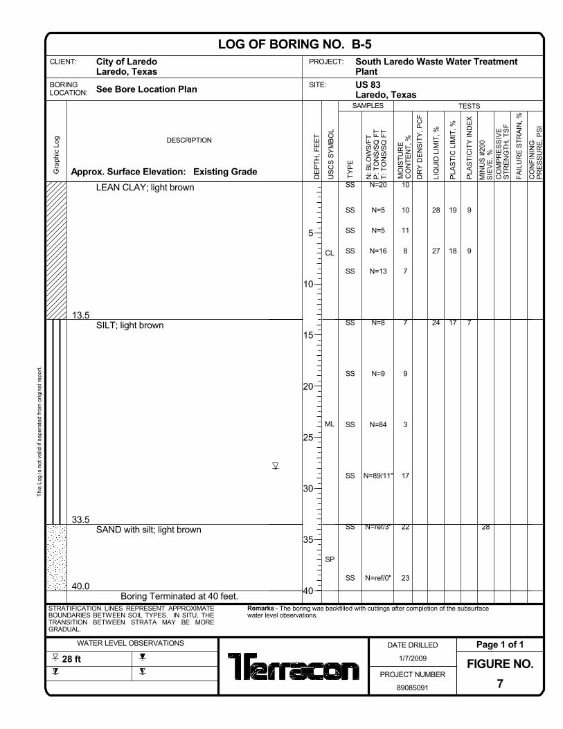
13.5
33.5
40.0
LEAN CLAY; light brown
SILT; light brown
SAND with silt; light brown
Boring Terminated at 40 feet.
CL
ML
SP
9
9
7
28
N=20
N=5
N=5
N=16
N=13
N=8
N=9
N=84
N=89/11"
N=ref/3"
N=ref/0"
SS
SS
SS
SS
SS
SS
SS
SS
SS
SS
SS
28
27
24
10
10
11
8
7
7
9
3
17
22
23
19
18
17
Approx. Surface Elevation: Existing GradeGra
phic
Log DESCRIPTION
Remarks - The boring was backfilled with cuttings after completion of the subsurfacewater level observations.
STRATIFICATION LINES REPRESENT APPROXIMATEBOUNDARIES BETWEEN SOIL TYPES. IN SITU, THETRANSITION BETWEEN STRATA MAY BE MOREGRADUAL.
CLIENT:
WATER LEVEL OBSERVATIONS
See Bore Location Plan
FIGURE NO.7
DATE DRILLED
1/7/2009
This
Log
is n
ot v
alid
if s
eper
ated
from
orig
inal
repo
rt.
Page 1 of 128 ft
PROJECT NUMBER
89085091
LOG OF BORING NO. B-5
BORINGLOCATION:
City of LaredoLaredo, Texas
US
CS
SY
MB
OL
PLA
STI
CIT
Y IN
DE
X
CO
MP
RE
SS
IVE
STR
EN
GTH
, TS
F
DE
PTH
, FE
ET
CO
NFI
NIN
GP
RE
SS
UR
E, P
SI
N: B
LOW
S/F
TP
: TO
NS
/SQ
FT
T: T
ON
S/S
Q F
T
TESTS
DR
Y D
EN
SIT
Y, P
CF
MIN
US
#20
0S
IEV
E, %
Laredo, TexasSAMPLES
5
10
15
20
25
30
35
40
PLA
STI
C L
IMIT
, %
South Laredo Waste Water TreatmentPlant
LIQ
UID
LIM
IT, %
US 83
TYP
E
MO
ISTU
RE
CO
NTE
NT,
%
SITE:
PROJECT:
FAIL
UR
E S
TRA
IN, %

6.0
30.0
SILT; light brown
LEAN CLAY; light brown
Boring Terminated at 30 feet.
ML
CL
7
8
9
12
99
96
N=14
N=9
N=14
N=8
N=10
N=16
N=19
N=23
N=23
SS
SS
SS
SS
SS
SS
SS
SS
SS
27
25
27
29
7
7
7
5
6
11
9
8
13
20
17
18
17
Approx. Surface Elevation: Existing GradeGra
phic
Log DESCRIPTION
Remarks - The boring was backfilled with cuttings after completion of the subsurfacewater level observations.
STRATIFICATION LINES REPRESENT APPROXIMATEBOUNDARIES BETWEEN SOIL TYPES. IN SITU, THETRANSITION BETWEEN STRATA MAY BE MOREGRADUAL.
CLIENT:
WATER LEVEL OBSERVATIONS
See Bore Location Plan
FIGURE NO.8
DATE DRILLED
1/7/2009
This
Log
is n
ot v
alid
if s
eper
ated
from
orig
inal
repo
rt.
Page 1 of 1
PROJECT NUMBER
89085091
LOG OF BORING NO. B-6
BORINGLOCATION:
City of LaredoLaredo, Texas
US
CS
SY
MB
OL
PLA
STI
CIT
Y IN
DE
X
CO
MP
RE
SS
IVE
STR
EN
GTH
, TS
F
DE
PTH
, FE
ET
CO
NFI
NIN
GP
RE
SS
UR
E, P
SI
N: B
LOW
S/F
TP
: TO
NS
/SQ
FT
T: T
ON
S/S
Q F
T
TESTS
DR
Y D
EN
SIT
Y, P
CF
MIN
US
#20
0S
IEV
E, %
Laredo, TexasSAMPLES
5
10
15
20
25
30
PLA
STI
C L
IMIT
, %
South Laredo Waste Water TreatmentPlant
LIQ
UID
LIM
IT, %
US 83
TYP
E
MO
ISTU
RE
CO
NTE
NT,
%
SITE:
PROJECT:
FAIL
UR
E S
TRA
IN, %

18.5
30.0
LEAN CLAY with sand; dark brown
- turns light brown between 8½ and 18½feet
SANDY SILT; light brown
Boring Terminated at 30 feet.
CL
ML
8
9
7
6
81
61
N=14
N=5
N=4
N=5
N=10
N=13
N=10
N=15
N=12
SS
SS
SS
SS
SS
SS
SS
SS
SS
30
27
25
22
15
9
10
9
8
5
8
10
18
22
18
18
16
Approx. Surface Elevation: Existing GradeGra
phic
Log DESCRIPTION
Remarks - The boring was backfilled with cuttings after completion of the subsurfacewater level observations.
STRATIFICATION LINES REPRESENT APPROXIMATEBOUNDARIES BETWEEN SOIL TYPES. IN SITU, THETRANSITION BETWEEN STRATA MAY BE MOREGRADUAL.
CLIENT:
WATER LEVEL OBSERVATIONS
See Bore Location Plan
FIGURE NO.9
DATE DRILLED
1/7/2009
This
Log
is n
ot v
alid
if s
eper
ated
from
orig
inal
repo
rt.
Page 1 of 1
PROJECT NUMBER
89085091
LOG OF BORING NO. B-7
BORINGLOCATION:
City of LaredoLaredo, Texas
US
CS
SY
MB
OL
PLA
STI
CIT
Y IN
DE
X
CO
MP
RE
SS
IVE
STR
EN
GTH
, TS
F
DE
PTH
, FE
ET
CO
NFI
NIN
GP
RE
SS
UR
E, P
SI
N: B
LOW
S/F
TP
: TO
NS
/SQ
FT
T: T
ON
S/S
Q F
T
TESTS
DR
Y D
EN
SIT
Y, P
CF
MIN
US
#20
0S
IEV
E, %
Laredo, TexasSAMPLES
5
10
15
20
25
30
PLA
STI
C L
IMIT
, %
South Laredo Waste Water TreatmentPlant
LIQ
UID
LIM
IT, %
US 83
TYP
E
MO
ISTU
RE
CO
NTE
NT,
%
SITE:
PROJECT:
FAIL
UR
E S
TRA
IN, %

40.0
LEAN CLAY; light brown
- some sand below 13½ feet
Boring Terminated at 40 feet.
CL
7
86
89
N=13
N=4
N=6
N=6
N=8
N=8
N=12
N=8
N=13
N=13
N=50/2"
SS
SS
SS
SS
SS
SS
SS
SS
SS
SS
SS
24 17
Approx. Surface Elevation: Existing GradeGra
phic
Log DESCRIPTION
Remarks - The boring was backfilled with cuttings after completion of the subsurfacewater level observations.
STRATIFICATION LINES REPRESENT APPROXIMATEBOUNDARIES BETWEEN SOIL TYPES. IN SITU, THETRANSITION BETWEEN STRATA MAY BE MOREGRADUAL.
CLIENT:
39 ft
WATER LEVEL OBSERVATIONS
See Bore Location Plan
FIGURE NO.10
DATE DRILLED
1/19/2009
This
Log
is n
ot v
alid
if s
eper
ated
from
orig
inal
repo
rt.
Page 1 of 140 ft
PROJECT NUMBER
89085091
LOG OF BORING NO. B-8
BORINGLOCATION:
City of LaredoLaredo, Texas
US
CS
SY
MB
OL
PLA
STI
CIT
Y IN
DE
X
CO
MP
RE
SS
IVE
STR
EN
GTH
, TS
F
DE
PTH
, FE
ET
CO
NFI
NIN
GP
RE
SS
UR
E, P
SI
N: B
LOW
S/F
TP
: TO
NS
/SQ
FT
T: T
ON
S/S
Q F
T
TESTS
DR
Y D
EN
SIT
Y, P
CF
MIN
US
#20
0S
IEV
E, %
Laredo, TexasSAMPLES
5
10
15
20
25
30
35
40
PLA
STI
C L
IMIT
, %
South Laredo Waste Water TreatmentPlant
LIQ
UID
LIM
IT, %
US 83
TYP
E
MO
ISTU
RE
CO
NTE
NT,
%
SITE:
PROJECT:
FAIL
UR
E S
TRA
IN, %

40.0
LEAN CLAY; light brown
- some gravel below 30 feet
Boring Terminated at 40 feet.
CL
9
7
7
9
22
95
84
N=14
N=13
N=11
N=10
N=11
N=16
N=16
N=19
N=15
N=20
N=20
SS
SS
SS
SS
SS
SS
SS
SS
SS
SS
SS
26
21
20
27
39
7
6
5
4
4
7
7
7
13
4
8
17
14
13
18
17
Approx. Surface Elevation: Existing GradeGra
phic
Log DESCRIPTION
Remarks - The boring was backfilled with cuttings after completion of the subsurfacewater level observations.
STRATIFICATION LINES REPRESENT APPROXIMATEBOUNDARIES BETWEEN SOIL TYPES. IN SITU, THETRANSITION BETWEEN STRATA MAY BE MOREGRADUAL.
CLIENT:
WATER LEVEL OBSERVATIONS
See Bore Location Plan
FIGURE NO.11
DATE DRILLED
1/7/2009
This
Log
is n
ot v
alid
if s
eper
ated
from
orig
inal
repo
rt.
Page 1 of 1
PROJECT NUMBER
89085091
LOG OF BORING NO. B-9
BORINGLOCATION:
City of LaredoLaredo, Texas
US
CS
SY
MB
OL
PLA
STI
CIT
Y IN
DE
X
CO
MP
RE
SS
IVE
STR
EN
GTH
, TS
F
DE
PTH
, FE
ET
CO
NFI
NIN
GP
RE
SS
UR
E, P
SI
N: B
LOW
S/F
TP
: TO
NS
/SQ
FT
T: T
ON
S/S
Q F
T
TESTS
DR
Y D
EN
SIT
Y, P
CF
MIN
US
#20
0S
IEV
E, %
Laredo, TexasSAMPLES
5
10
15
20
25
30
35
40
PLA
STI
C L
IMIT
, %
South Laredo Waste Water TreatmentPlant
LIQ
UID
LIM
IT, %
US 83
TYP
E
MO
ISTU
RE
CO
NTE
NT,
%
SITE:
PROJECT:
FAIL
UR
E S
TRA
IN, %

4.5
28.5
40.0
LEAN CLAY; light brown
SILT with sand; light brown
LEAN CLAY with sand; brown
Boring Terminated at 40 feet.
CL
ML
CL
8
7
6
15
84
76
N=25
N=11
N=6
N=13
N=10
N=8
N=11
N=11
N=14
N=20
N=10
SS
SS
SS
SS
SS
SS
SS
SS
SS
SS
SS
27
27
21
30
7
7
7
8
7
11
13
17
13
16
23
19
20
15
15
Approx. Surface Elevation: Existing GradeGra
phic
Log DESCRIPTION
Remarks - The boring was backfilled with cuttings after completion of the subsurfacewater level observations.
STRATIFICATION LINES REPRESENT APPROXIMATEBOUNDARIES BETWEEN SOIL TYPES. IN SITU, THETRANSITION BETWEEN STRATA MAY BE MOREGRADUAL.
CLIENT:
WATER LEVEL OBSERVATIONS
See Bore Location Plan
FIGURE NO.12
DATE DRILLED
1/8/2009
This
Log
is n
ot v
alid
if s
eper
ated
from
orig
inal
repo
rt.
Page 1 of 1
PROJECT NUMBER
89085091
LOG OF BORING NO. B-10
BORINGLOCATION:
City of LaredoLaredo, Texas
US
CS
SY
MB
OL
PLA
STI
CIT
Y IN
DE
X
CO
MP
RE
SS
IVE
STR
EN
GTH
, TS
F
DE
PTH
, FE
ET
CO
NFI
NIN
GP
RE
SS
UR
E, P
SI
N: B
LOW
S/F
TP
: TO
NS
/SQ
FT
T: T
ON
S/S
Q F
T
TESTS
DR
Y D
EN
SIT
Y, P
CF
MIN
US
#20
0S
IEV
E, %
Laredo, TexasSAMPLES
5
10
15
20
25
30
35
40
PLA
STI
C L
IMIT
, %
South Laredo Waste Water TreatmentPlant
LIQ
UID
LIM
IT, %
US 83
TYP
E
MO
ISTU
RE
CO
NTE
NT,
%
SITE:
PROJECT:
FAIL
UR
E S
TRA
IN, %

15.0
SANDY SILT; light brown
Boring Terminated at 15 feet.
ML
5
6
5
72
67
N=6
N=6
N=2
N=4
N=14
N=6
SS
SS
SS
SS
SS
SS
26
22
25
8
16
16
13
23
8
21
16
20
Approx. Surface Elevation: Existing GradeGra
phic
Log DESCRIPTION
Remarks - The boring was backfilled with cuttings after completion of the subsurfacewater level observations.
STRATIFICATION LINES REPRESENT APPROXIMATEBOUNDARIES BETWEEN SOIL TYPES. IN SITU, THETRANSITION BETWEEN STRATA MAY BE MOREGRADUAL.
CLIENT:
WATER LEVEL OBSERVATIONS
See Bore Location Plan
FIGURE NO.13
DATE DRILLED
1/8/2009
This
Log
is n
ot v
alid
if s
eper
ated
from
orig
inal
repo
rt.
Page 1 of 1
PROJECT NUMBER
89085091
LOG OF BORING NO. B-11
BORINGLOCATION:
City of LaredoLaredo, Texas
US
CS
SY
MB
OL
PLA
STI
CIT
Y IN
DE
X
CO
MP
RE
SS
IVE
STR
EN
GTH
, TS
F
DE
PTH
, FE
ET
CO
NFI
NIN
GP
RE
SS
UR
E, P
SI
N: B
LOW
S/F
TP
: TO
NS
/SQ
FT
T: T
ON
S/S
Q F
T
TESTS
DR
Y D
EN
SIT
Y, P
CF
MIN
US
#20
0S
IEV
E, %
Laredo, TexasSAMPLES
5
10
15
PLA
STI
C L
IMIT
, %
South Laredo Waste Water TreatmentPlant
LIQ
UID
LIM
IT, %
US 83
TYP
E
MO
ISTU
RE
CO
NTE
NT,
%
SITE:
PROJECT:
FAIL
UR
E S
TRA
IN, %
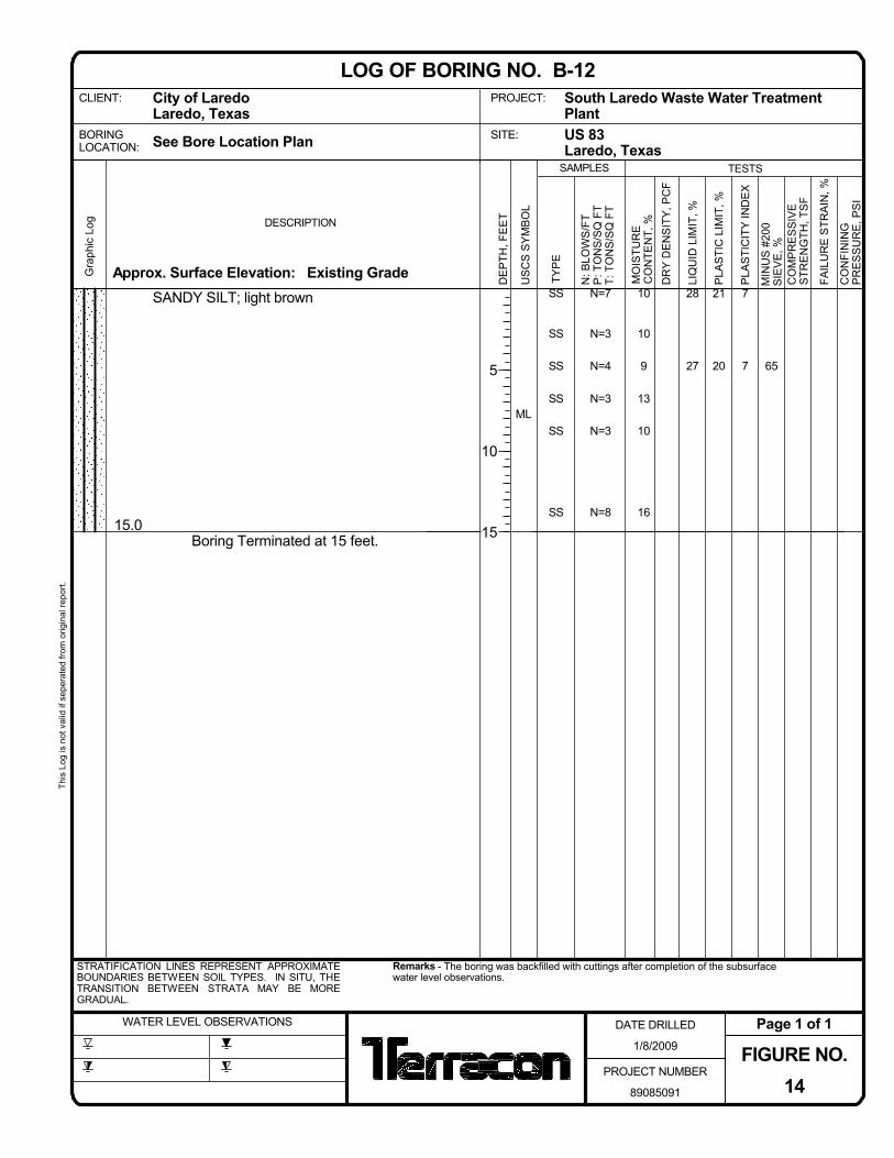
15.0
SANDY SILT; light brown
Boring Terminated at 15 feet.
ML
7
7 65
N=7
N=3
N=4
N=3
N=3
N=8
SS
SS
SS
SS
SS
SS
28
27
10
10
9
13
10
16
21
20
Approx. Surface Elevation: Existing GradeGra
phic
Log DESCRIPTION
Remarks - The boring was backfilled with cuttings after completion of the subsurfacewater level observations.
STRATIFICATION LINES REPRESENT APPROXIMATEBOUNDARIES BETWEEN SOIL TYPES. IN SITU, THETRANSITION BETWEEN STRATA MAY BE MOREGRADUAL.
CLIENT:
WATER LEVEL OBSERVATIONS
See Bore Location Plan
FIGURE NO.14
DATE DRILLED
1/8/2009
This
Log
is n
ot v
alid
if s
eper
ated
from
orig
inal
repo
rt.
Page 1 of 1
PROJECT NUMBER
89085091
LOG OF BORING NO. B-12
BORINGLOCATION:
City of LaredoLaredo, Texas
US
CS
SY
MB
OL
PLA
STI
CIT
Y IN
DE
X
CO
MP
RE
SS
IVE
STR
EN
GTH
, TS
F
DE
PTH
, FE
ET
CO
NFI
NIN
GP
RE
SS
UR
E, P
SI
N: B
LOW
S/F
TP
: TO
NS
/SQ
FT
T: T
ON
S/S
Q F
T
TESTS
DR
Y D
EN
SIT
Y, P
CF
MIN
US
#20
0S
IEV
E, %
Laredo, TexasSAMPLES
5
10
15
PLA
STI
C L
IMIT
, %
South Laredo Waste Water TreatmentPlant
LIQ
UID
LIM
IT, %
US 83
TYP
E
MO
ISTU
RE
CO
NTE
NT,
%
SITE:
PROJECT:
FAIL
UR
E S
TRA
IN, %

6.0
15.0
SANDY SILT; light brown
LEAN CLAY with sand; light brown
Boring Terminated at 15 feet.
ML
CL
3
4
10
72
73
N=18
N=4
N=4
N=5
N=5
N=6
SS
SS
SS
SS
SS
SS
25
23
24
10
6
7
6
8
6
22
19
14
Approx. Surface Elevation: Existing GradeGra
phic
Log DESCRIPTION
Remarks - The boring was backfilled with cuttings after completion of the subsurfacewater level observations.
STRATIFICATION LINES REPRESENT APPROXIMATEBOUNDARIES BETWEEN SOIL TYPES. IN SITU, THETRANSITION BETWEEN STRATA MAY BE MOREGRADUAL.
CLIENT:
WATER LEVEL OBSERVATIONS
See Bore Location Plan
FIGURE NO.15
DATE DRILLED
1/8/2009
This
Log
is n
ot v
alid
if s
eper
ated
from
orig
inal
repo
rt.
Page 1 of 1
PROJECT NUMBER
89085091
LOG OF BORING NO. B-13
BORINGLOCATION:
City of LaredoLaredo, Texas
US
CS
SY
MB
OL
PLA
STI
CIT
Y IN
DE
X
CO
MP
RE
SS
IVE
STR
EN
GTH
, TS
F
DE
PTH
, FE
ET
CO
NFI
NIN
GP
RE
SS
UR
E, P
SI
N: B
LOW
S/F
TP
: TO
NS
/SQ
FT
T: T
ON
S/S
Q F
T
TESTS
DR
Y D
EN
SIT
Y, P
CF
MIN
US
#20
0S
IEV
E, %
Laredo, TexasSAMPLES
5
10
15
PLA
STI
C L
IMIT
, %
South Laredo Waste Water TreatmentPlant
LIQ
UID
LIM
IT, %
US 83
TYP
E
MO
ISTU
RE
CO
NTE
NT,
%
SITE:
PROJECT:
FAIL
UR
E S
TRA
IN, %

8.0
15.0
SILT; light brown, some sand
LEAN CLAY; light brown
Boring Terminated at 15 feet.
ML
CL
6
7
11
78
90
N=14
N=6
N=7
N=6
N=8
N=7
SS
SS
SS
SS
SS
SS
25
27
24
10
7
8
8
9
10
19
20
13
Approx. Surface Elevation: Existing GradeGra
phic
Log DESCRIPTION
Remarks - The boring was backfilled with cuttings after completion of the subsurfacewater level observations.
STRATIFICATION LINES REPRESENT APPROXIMATEBOUNDARIES BETWEEN SOIL TYPES. IN SITU, THETRANSITION BETWEEN STRATA MAY BE MOREGRADUAL.
CLIENT:
WATER LEVEL OBSERVATIONS
See Bore Location Plan
FIGURE NO.16
DATE DRILLED
1/8/2009
This
Log
is n
ot v
alid
if s
eper
ated
from
orig
inal
repo
rt.
Page 1 of 1
PROJECT NUMBER
89085091
LOG OF BORING NO. B-14
BORINGLOCATION:
City of LaredoLaredo, Texas
US
CS
SY
MB
OL
PLA
STI
CIT
Y IN
DE
X
CO
MP
RE
SS
IVE
STR
EN
GTH
, TS
F
DE
PTH
, FE
ET
CO
NFI
NIN
GP
RE
SS
UR
E, P
SI
N: B
LOW
S/F
TP
: TO
NS
/SQ
FT
T: T
ON
S/S
Q F
T
TESTS
DR
Y D
EN
SIT
Y, P
CF
MIN
US
#20
0S
IEV
E, %
Laredo, TexasSAMPLES
5
10
15
PLA
STI
C L
IMIT
, %
South Laredo Waste Water TreatmentPlant
LIQ
UID
LIM
IT, %
US 83
TYP
E
MO
ISTU
RE
CO
NTE
NT,
%
SITE:
PROJECT:
FAIL
UR
E S
TRA
IN, %

15.0
LEAN CLAY; light brown, some sand
Boring Terminated at 15 feet.
CL
7
10
7
90
N=9
N=4
N=2
N=4
N=7
N=4
SS
SS
SS
SS
SS
SS
28
24
23
5
11
11
12
11
15
21
14
16
Approx. Surface Elevation: Existing GradeGra
phic
Log DESCRIPTION
Remarks - The boring was backfilled with cuttings after completion of the subsurfacewater level observations.
STRATIFICATION LINES REPRESENT APPROXIMATEBOUNDARIES BETWEEN SOIL TYPES. IN SITU, THETRANSITION BETWEEN STRATA MAY BE MOREGRADUAL.
CLIENT:
WATER LEVEL OBSERVATIONS
See Bore Location Plan
FIGURE NO.17
DATE DRILLED
1/8/2009
This
Log
is n
ot v
alid
if s
eper
ated
from
orig
inal
repo
rt.
Page 1 of 1
PROJECT NUMBER
89085091
LOG OF BORING NO. B-15
BORINGLOCATION:
City of LaredoLaredo, Texas
US
CS
SY
MB
OL
PLA
STI
CIT
Y IN
DE
X
CO
MP
RE
SS
IVE
STR
EN
GTH
, TS
F
DE
PTH
, FE
ET
CO
NFI
NIN
GP
RE
SS
UR
E, P
SI
N: B
LOW
S/F
TP
: TO
NS
/SQ
FT
T: T
ON
S/S
Q F
T
TESTS
DR
Y D
EN
SIT
Y, P
CF
MIN
US
#20
0S
IEV
E, %
Laredo, TexasSAMPLES
5
10
15
PLA
STI
C L
IMIT
, %
South Laredo Waste Water TreatmentPlant
LIQ
UID
LIM
IT, %
US 83
TYP
E
MO
ISTU
RE
CO
NTE
NT,
%
SITE:
PROJECT:
FAIL
UR
E S
TRA
IN, %

15.0
LEAN CLAY; light brown, some sand
Boring Terminated at 15 feet.
CL
9
9
7
93
N=15
N=4
N=6
N=4
N=6
N=6
SS
SS
SS
SS
SS
SS
31
30
25
8
11
13
9
7
5
22
21
18
Approx. Surface Elevation: Existing GradeGra
phic
Log DESCRIPTION
Remarks - The boring was backfilled with cuttings after completion of the subsurfacewater level observations.
STRATIFICATION LINES REPRESENT APPROXIMATEBOUNDARIES BETWEEN SOIL TYPES. IN SITU, THETRANSITION BETWEEN STRATA MAY BE MOREGRADUAL.
CLIENT:
WATER LEVEL OBSERVATIONS
See Bore Location Plan
FIGURE NO.18
DATE DRILLED
1/8/2009
This
Log
is n
ot v
alid
if s
eper
ated
from
orig
inal
repo
rt.
Page 1 of 1
PROJECT NUMBER
89085091
LOG OF BORING NO. B-16
BORINGLOCATION:
City of LaredoLaredo, Texas
US
CS
SY
MB
OL
PLA
STI
CIT
Y IN
DE
X
CO
MP
RE
SS
IVE
STR
EN
GTH
, TS
F
DE
PTH
, FE
ET
CO
NFI
NIN
GP
RE
SS
UR
E, P
SI
N: B
LOW
S/F
TP
: TO
NS
/SQ
FT
T: T
ON
S/S
Q F
T
TESTS
DR
Y D
EN
SIT
Y, P
CF
MIN
US
#20
0S
IEV
E, %
Laredo, TexasSAMPLES
5
10
15
PLA
STI
C L
IMIT
, %
South Laredo Waste Water TreatmentPlant
LIQ
UID
LIM
IT, %
US 83
TYP
E
MO
ISTU
RE
CO
NTE
NT,
%
SITE:
PROJECT:
FAIL
UR
E S
TRA
IN, %

4.0
15.0
SILT; light brown
LEAN CLAY; light brown, some sand
Boring Terminated at 15 feet.
ML
CL
6
9 88
N=12
N=11
N=11
N=8
N=7
N=8
SS
SS
SS
SS
SS
SS
25
26
19
17
Approx. Surface Elevation: Existing GradeGra
phic
Log DESCRIPTION
Remarks - The boring was backfilled with cuttings after completion of the subsurfacewater level observations.
STRATIFICATION LINES REPRESENT APPROXIMATEBOUNDARIES BETWEEN SOIL TYPES. IN SITU, THETRANSITION BETWEEN STRATA MAY BE MOREGRADUAL.
CLIENT:
WATER LEVEL OBSERVATIONS
See Bore Location Plan
FIGURE NO.19
DATE DRILLED
1/9/2009
This
Log
is n
ot v
alid
if s
eper
ated
from
orig
inal
repo
rt.
Page 1 of 1
PROJECT NUMBER
89085091
LOG OF BORING NO. B-17
BORINGLOCATION:
City of LaredoLaredo, Texas
US
CS
SY
MB
OL
PLA
STI
CIT
Y IN
DE
X
CO
MP
RE
SS
IVE
STR
EN
GTH
, TS
F
DE
PTH
, FE
ET
CO
NFI
NIN
GP
RE
SS
UR
E, P
SI
N: B
LOW
S/F
TP
: TO
NS
/SQ
FT
T: T
ON
S/S
Q F
T
TESTS
DR
Y D
EN
SIT
Y, P
CF
MIN
US
#20
0S
IEV
E, %
Laredo, TexasSAMPLES
5
10
15
PLA
STI
C L
IMIT
, %
South Laredo Waste Water TreatmentPlant
LIQ
UID
LIM
IT, %
US 83
TYP
E
MO
ISTU
RE
CO
NTE
NT,
%
SITE:
PROJECT:
FAIL
UR
E S
TRA
IN, %

15.0
SILT; light brown, some sand
Boring Terminated at 15 feet.
ML
5
6
80
N=8
N=3
N=5
N=9
N=10
N=10
SS
SS
SS
SS
SS
SS
25
26
9
10
9
8
7
8
20
20
Approx. Surface Elevation: Existing GradeGra
phic
Log DESCRIPTION
Remarks - The boring was backfilled with cuttings after completion of the subsurfacewater level observations.
STRATIFICATION LINES REPRESENT APPROXIMATEBOUNDARIES BETWEEN SOIL TYPES. IN SITU, THETRANSITION BETWEEN STRATA MAY BE MOREGRADUAL.
CLIENT:
WATER LEVEL OBSERVATIONS
See Bore Location Plan
FIGURE NO.20
DATE DRILLED
1/9/2009
This
Log
is n
ot v
alid
if s
eper
ated
from
orig
inal
repo
rt.
Page 1 of 1
PROJECT NUMBER
89085091
LOG OF BORING NO. B-18
BORINGLOCATION:
City of LaredoLaredo, Texas
US
CS
SY
MB
OL
PLA
STI
CIT
Y IN
DE
X
CO
MP
RE
SS
IVE
STR
EN
GTH
, TS
F
DE
PTH
, FE
ET
CO
NFI
NIN
GP
RE
SS
UR
E, P
SI
N: B
LOW
S/F
TP
: TO
NS
/SQ
FT
T: T
ON
S/S
Q F
T
TESTS
DR
Y D
EN
SIT
Y, P
CF
MIN
US
#20
0S
IEV
E, %
Laredo, TexasSAMPLES
5
10
15
PLA
STI
C L
IMIT
, %
South Laredo Waste Water TreatmentPlant
LIQ
UID
LIM
IT, %
US 83
TYP
E
MO
ISTU
RE
CO
NTE
NT,
%
SITE:
PROJECT:
FAIL
UR
E S
TRA
IN, %
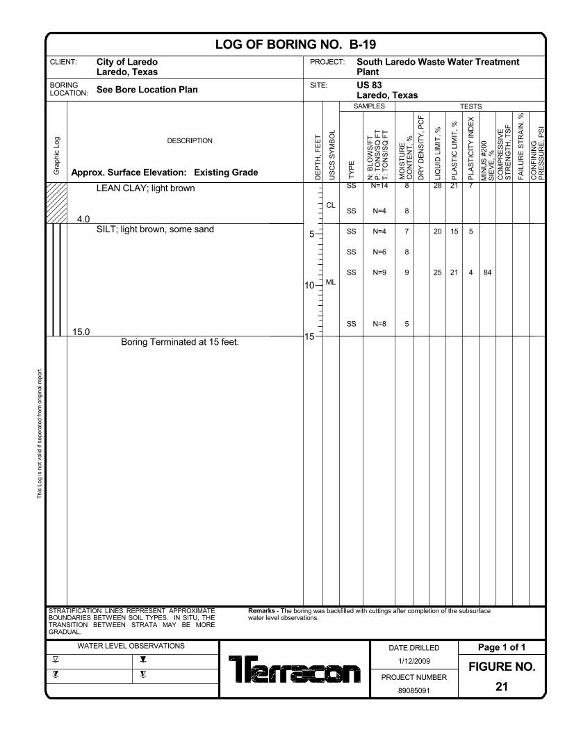
4.0
15.0
LEAN CLAY; light brown
SILT; light brown, some sand
Boring Terminated at 15 feet.
CL
ML
7
5
4 84
N=14
N=4
N=4
N=6
N=9
N=8
SS
SS
SS
SS
SS
SS
28
20
25
8
8
7
8
9
5
21
15
21
Approx. Surface Elevation: Existing GradeGra
phic
Log DESCRIPTION
Remarks - The boring was backfilled with cuttings after completion of the subsurfacewater level observations.
STRATIFICATION LINES REPRESENT APPROXIMATEBOUNDARIES BETWEEN SOIL TYPES. IN SITU, THETRANSITION BETWEEN STRATA MAY BE MOREGRADUAL.
CLIENT:
WATER LEVEL OBSERVATIONS
See Bore Location Plan
FIGURE NO.21
DATE DRILLED
1/12/2009
This
Log
is n
ot v
alid
if s
eper
ated
from
orig
inal
repo
rt.
Page 1 of 1
PROJECT NUMBER
89085091
LOG OF BORING NO. B-19
BORINGLOCATION:
City of LaredoLaredo, Texas
US
CS
SY
MB
OL
PLA
STI
CIT
Y IN
DE
X
CO
MP
RE
SS
IVE
STR
EN
GTH
, TS
F
DE
PTH
, FE
ET
CO
NFI
NIN
GP
RE
SS
UR
E, P
SI
N: B
LOW
S/F
TP
: TO
NS
/SQ
FT
T: T
ON
S/S
Q F
T
TESTS
DR
Y D
EN
SIT
Y, P
CF
MIN
US
#20
0S
IEV
E, %
Laredo, TexasSAMPLES
5
10
15
PLA
STI
C L
IMIT
, %
South Laredo Waste Water TreatmentPlant
LIQ
UID
LIM
IT, %
US 83
TYP
E
MO
ISTU
RE
CO
NTE
NT,
%
SITE:
PROJECT:
FAIL
UR
E S
TRA
IN, %

15.0
SILT with sand, light brown
Boring Terminated at 15 feet.
ML
6
5
80
N=18
N=10
N=11
N=12
N=9
N=10
SS
SS
SS
SS
SS
SS
29
25
9
6
6
5
7
6
23
20
Approx. Surface Elevation: Existing GradeGra
phic
Log DESCRIPTION
Remarks - The boring was backfilled with cuttings after completion of the subsurfacewater level observations.
STRATIFICATION LINES REPRESENT APPROXIMATEBOUNDARIES BETWEEN SOIL TYPES. IN SITU, THETRANSITION BETWEEN STRATA MAY BE MOREGRADUAL.
CLIENT:
WATER LEVEL OBSERVATIONS
See Bore Location Plan
FIGURE NO.22
DATE DRILLED
1/9/2009
This
Log
is n
ot v
alid
if s
eper
ated
from
orig
inal
repo
rt.
Page 1 of 1
PROJECT NUMBER
89085091
LOG OF BORING NO. B-20
BORINGLOCATION:
City of LaredoLaredo, Texas
US
CS
SY
MB
OL
PLA
STI
CIT
Y IN
DE
X
CO
MP
RE
SS
IVE
STR
EN
GTH
, TS
F
DE
PTH
, FE
ET
CO
NFI
NIN
GP
RE
SS
UR
E, P
SI
N: B
LOW
S/F
TP
: TO
NS
/SQ
FT
T: T
ON
S/S
Q F
T
TESTS
DR
Y D
EN
SIT
Y, P
CF
MIN
US
#20
0S
IEV
E, %
Laredo, TexasSAMPLES
5
10
15
PLA
STI
C L
IMIT
, %
South Laredo Waste Water TreatmentPlant
LIQ
UID
LIM
IT, %
US 83
TYP
E
MO
ISTU
RE
CO
NTE
NT,
%
SITE:
PROJECT:
FAIL
UR
E S
TRA
IN, %
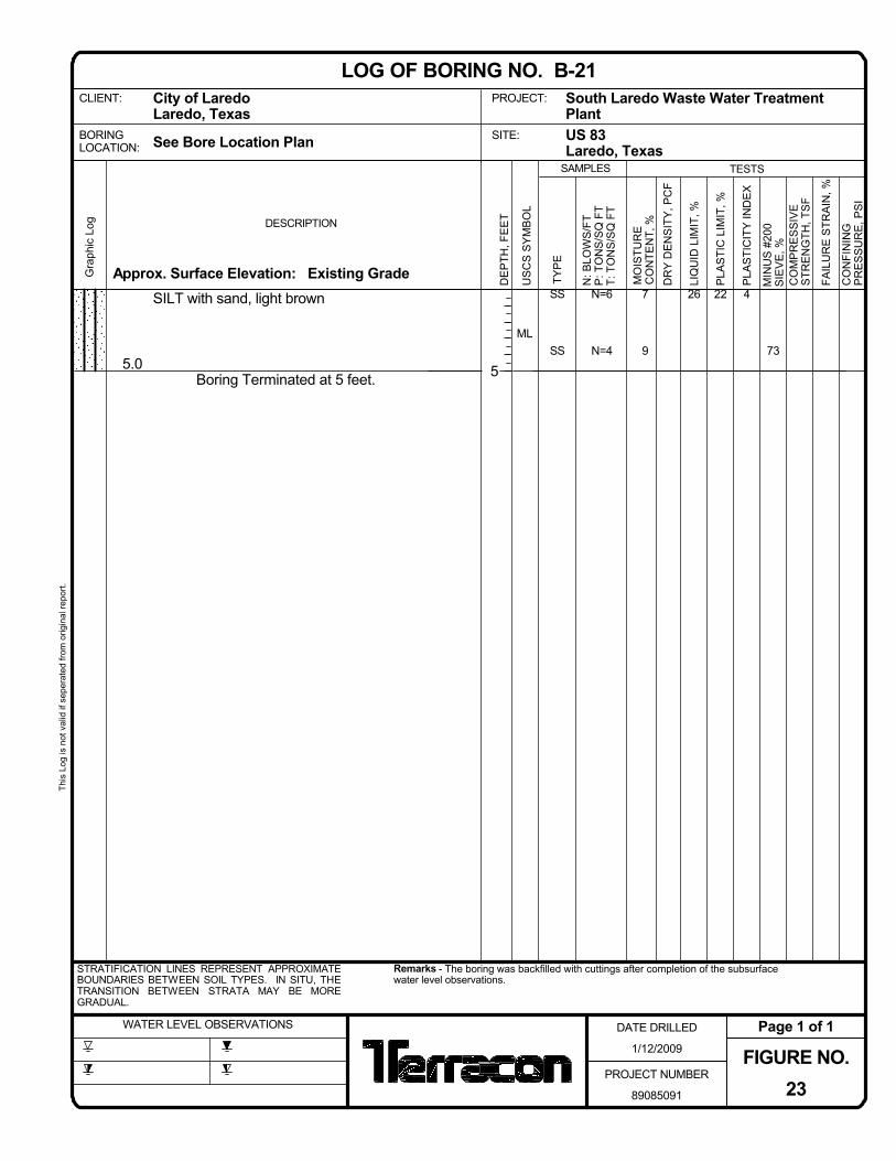
5.0
SILT with sand, light brown
Boring Terminated at 5 feet.
ML
4
73
N=6
N=4
SS
SS
267
9
22
Approx. Surface Elevation: Existing GradeGra
phic
Log DESCRIPTION
Remarks - The boring was backfilled with cuttings after completion of the subsurfacewater level observations.
STRATIFICATION LINES REPRESENT APPROXIMATEBOUNDARIES BETWEEN SOIL TYPES. IN SITU, THETRANSITION BETWEEN STRATA MAY BE MOREGRADUAL.
CLIENT:
WATER LEVEL OBSERVATIONS
See Bore Location Plan
FIGURE NO.23
DATE DRILLED
1/12/2009
This
Log
is n
ot v
alid
if s
eper
ated
from
orig
inal
repo
rt.
Page 1 of 1
PROJECT NUMBER
89085091
LOG OF BORING NO. B-21
BORINGLOCATION:
City of LaredoLaredo, Texas
US
CS
SY
MB
OL
PLA
STI
CIT
Y IN
DE
X
CO
MP
RE
SS
IVE
STR
EN
GTH
, TS
F
DE
PTH
, FE
ET
CO
NFI
NIN
GP
RE
SS
UR
E, P
SI
N: B
LOW
S/F
TP
: TO
NS
/SQ
FT
T: T
ON
S/S
Q F
T
TESTS
DR
Y D
EN
SIT
Y, P
CF
MIN
US
#20
0S
IEV
E, %
Laredo, TexasSAMPLES
5
PLA
STI
C L
IMIT
, %
South Laredo Waste Water TreatmentPlant
LIQ
UID
LIM
IT, %
US 83
TYP
E
MO
ISTU
RE
CO
NTE
NT,
%
SITE:
PROJECT:
FAIL
UR
E S
TRA
IN, %

4.0
15.0
LEAN CLAY; light brown
SILT with sand, light brown
- sandy silt between 8½ and 10 feet
Boring Terminated at 15 feet.
CL
ML
8
6
3
84
58
79
N=14
N=8
N=9
N=11
N=9
N=10
SS
SS
SS
SS
SS
SS
28
26
21
8
8
7
7
7
8
20
20
18
Approx. Surface Elevation: Existing GradeGra
phic
Log DESCRIPTION
Remarks - The boring was backfilled with cuttings after completion of the subsurfacewater level observations.
STRATIFICATION LINES REPRESENT APPROXIMATEBOUNDARIES BETWEEN SOIL TYPES. IN SITU, THETRANSITION BETWEEN STRATA MAY BE MOREGRADUAL.
CLIENT:
WATER LEVEL OBSERVATIONS
See Bore Location Plan
FIGURE NO.24
DATE DRILLED
1/9/2009
This
Log
is n
ot v
alid
if s
eper
ated
from
orig
inal
repo
rt.
Page 1 of 1
PROJECT NUMBER
89085091
LOG OF BORING NO. B-22
BORINGLOCATION:
City of LaredoLaredo, Texas
US
CS
SY
MB
OL
PLA
STI
CIT
Y IN
DE
X
CO
MP
RE
SS
IVE
STR
EN
GTH
, TS
F
DE
PTH
, FE
ET
CO
NFI
NIN
GP
RE
SS
UR
E, P
SI
N: B
LOW
S/F
TP
: TO
NS
/SQ
FT
T: T
ON
S/S
Q F
T
TESTS
DR
Y D
EN
SIT
Y, P
CF
MIN
US
#20
0S
IEV
E, %
Laredo, TexasSAMPLES
5
10
15
PLA
STI
C L
IMIT
, %
South Laredo Waste Water TreatmentPlant
LIQ
UID
LIM
IT, %
US 83
TYP
E
MO
ISTU
RE
CO
NTE
NT,
%
SITE:
PROJECT:
FAIL
UR
E S
TRA
IN, %

5.0
LEAN CLAY; light brown
Boring Terminated at 5 feet.
CL
9N=22
N=10
SS
SS
309
7
21
Approx. Surface Elevation: Existing GradeGra
phic
Log DESCRIPTION
Remarks - The boring was backfilled with cuttings after completion of the subsurfacewater level observations.
STRATIFICATION LINES REPRESENT APPROXIMATEBOUNDARIES BETWEEN SOIL TYPES. IN SITU, THETRANSITION BETWEEN STRATA MAY BE MOREGRADUAL.
CLIENT:
WATER LEVEL OBSERVATIONS
See Bore Location Plan
FIGURE NO.25
DATE DRILLED
1/9/2009
This
Log
is n
ot v
alid
if s
eper
ated
from
orig
inal
repo
rt.
Page 1 of 1
PROJECT NUMBER
89085091
LOG OF BORING NO. PT-1
BORINGLOCATION:
City of LaredoLaredo, Texas
US
CS
SY
MB
OL
PLA
STI
CIT
Y IN
DE
X
CO
MP
RE
SS
IVE
STR
EN
GTH
, TS
F
DE
PTH
, FE
ET
CO
NFI
NIN
GP
RE
SS
UR
E, P
SI
N: B
LOW
S/F
TP
: TO
NS
/SQ
FT
T: T
ON
S/S
Q F
T
TESTS
DR
Y D
EN
SIT
Y, P
CF
MIN
US
#20
0S
IEV
E, %
Laredo, TexasSAMPLES
5
PLA
STI
C L
IMIT
, %
South Laredo Waste Water TreatmentPlant
LIQ
UID
LIM
IT, %
US 83
TYP
E
MO
ISTU
RE
CO
NTE
NT,
%
SITE:
PROJECT:
FAIL
UR
E S
TRA
IN, %

South Laredo Waste Water Treatment Plant (WWTP) Project No. 89085091 March 24, 2009
APPENDIX B
Laboratory Test Results General Notes
Unified Soil Classification System

South Laredo Waste Water Treatment Plant (WWTP) Project No. 89085091 March 24, 2009
LABORATORY TEST RESULTS General Soil mechanics laboratory tests procedures are performed in accordance with accepted geotechnical engineering practice. These procedures are described in detail in the most current edition of the American Society for Testing and Materials (ASTM) book titled Annual Book of ASTM Standards or as outlined in the book titled: Soil Testing for Engineers, by T. William Lambe. Testing Program The laboratory testing program was directed towards evaluating the physical and engineering properties of the subsoils. Tests were performed in general accordance with the following standards.
Laboratory Test Applicable Test Standard Moisture Content ASTM D 2216 Liquid Limit, Plastic Limit and Plasticity Index of Soil ASTM D 4318 Amount of Material Finer than the No 200 (75-μm) Sieve ASTM D 1140 The laboratory test results are tabulated either adjacent to the corresponding sample depths on the individual boring logs in Appendix A or on attached sheets that may be provided in this Appendix. Laboratory test results were used to classify the soils encountered in substantial accordance with the Unified Soil Classification System. Sample Disposal All samples were returned to our laboratory. The samples not tested in the laboratory will be stored for a period of 30 days subsequent to submittal of this report and will be discarded after this period, unless other arrangements are made prior to the disposal period.

GENERAL NOTES DRILLING & SAMPLING SYMBOLS: SS: Split Spoon - 1-3/8" I.D., 2" O.D., unless otherwise noted HS: Hollow Stem Auger ST: Thin-Walled Tube - 2" O.D., unless otherwise noted PA: Power Auger RS: Ring Sampler - 2.42" I.D., 3" O.D., unless otherwise noted HA: Hand Auger DB: Diamond Bit Coring - 4", N, B RB: Rock Bit BS: Bulk Sample or Auger Sample WB: Wash Boring or Mud Rotary
The number of blows required to advance a standard 2-inch O.D. split-spoon sampler (SS) the last 12 inches of the total 18-inch penetration with a 140-pound hammer falling 30 inches is considered the “Standard Penetration” or “N-value”.
WATER LEVEL MEASUREMENT SYMBOLS: WL: Water Level WS: While Sampling N/E: Not Encountered WCI: Wet Cave in WD: While Drilling DCI: Dry Cave in BCR: Before Casing Removal AB: After Boring ACR: After Casing Removal
Water levels indicated on the boring logs are the levels measured in the borings at the times indicated. Groundwater levels at other times and other locations across the site could vary. In pervious soils, the indicated levels may reflect the location of groundwater. In low permeability soils, the accurate determination of groundwater levels may not be possible with only short-term observations.
DESCRIPTIVE SOIL CLASSIFICATION: Soil classification is based on the Unified Classification System. Coarse Grained Soils have more than 50% of their dry weight retained on a #200 sieve; their principal descriptors are: boulders, cobbles, gravel or sand. Fine Grained Soils have less than 50% of their dry weight retained on a #200 sieve; they are principally described as clays if they are plastic, and silts if they are slightly plastic or non-plastic. Major constituents may be added as modifiers and minor constituents may be added according to the relative proportions based on grain size. In addition to gradation, coarse-grained soils are defined on the basis of their in-place relative density and fine-grained soils on the basis of their consistency.
CONSISTENCY OF FINE-GRAINED SOILS RELATIVE DENSITY OF COARSE-GRAINED SOILS
Unconfined
Compressive Strength, Qu, psf
Standard Penetration or N-value (SS)
Blows/Ft.
Consistency
Standard Penetration
or N-value (SS) Blows/Ft.
Relative Density < 500 <2 Very Soft 0 – 3 Very Loose 500 – 1,000 2-3 Soft 4 – 9 Loose 1,001 – 2,000 4-6 Medium Stiff 10 – 29 Medium Dense 2,001 – 4,000 7-12 Stiff 30 – 49 Dense 4,001 – 8,000 13-26 Very Stiff 50+ Very Dense 8,000+ 26+ Hard
RELATIVE PROPORTIONS OF SAND AND GRAVEL GRAIN SIZE TERMINOLOGY Descriptive Term(s) of other
constituents Percent of Dry Weight
Major Component of Sample
Particle Size
Trace < 15 Boulders Over 12 in. (300mm) With 15 – 29 Cobbles 12 in. to 3 in. (300mm to 75 mm)
Modifier > 30 Gravel 3 in. to #4 sieve (75mm to 4.75 mm)
RELATIVE PROPORTIONS OF FINES Sand
Silt or Clay #4 to #200 sieve (4.75mm to 0.075mm)
Passing #200 Sieve (0.075mm)
PLASTICITY DESCRIPTION Descriptive Term(s) of other constituents
Percent of Dry Weight
Term Plasticity Index
Trace With
Modifiers
< 5 5 – 12 > 12
Non-plastic
Low Medium
High
0 1-10 11-30 30+

Form 111—6/98
UNIFIED SOIL CLASSIFICATION SYSTEM Criteria for Assigning Group Symbols and Group Names Using Laboratory TestsA Soil Classification
Group Symbol
Group NameB
Cu ≥ 4 and 1 ≤ Cc ≤ 3E GW Well-graded gravelF Clean Gravels Less than 5% finesC Cu < 4 and/or 1 > Cc > 3E GP Poorly graded gravelF
Fines classify as ML or MH GM Silty gravelF,G, H
Coarse Grained Soils
More than 50% retained
on No. 200 sieve
Gravels More than 50% of coarse fraction retained on No. 4 sieve Gravels with Fines More
than 12% finesC Fines classify as CL or CH GC Clayey gravelF,G,H
Cu ≥ 6 and 1 ≤ Cc ≤ 3E SW Well-graded sandI Clean Sands Less than 5% finesD Cu < 6 and/or 1 > Cc > 3E SP Poorly graded sandI
Fines classify as ML or MH SM Silty sandG,H,I
Sands 50% or more of coarse fraction passes No. 4 sieve Sands with Fines
More than 12% finesD Fines Classify as CL or CH SC Clayey sandG,H,I
PI > 7 and plots on or above “A” lineJ CL Lean clayK,L,M Silts and Clays Liquid limit less than 50
inorganic
PI < 4 or plots below “A” lineJ ML SiltK,L,M
Liquid limit - oven dried Organic clayK,L,M,N
Fine-Grained Soils 50% or more passes the No. 200 sieve
organic
Liquid limit - not dried < 0.75 OL
Organic siltK,L,M,O
inorganic PI plots on or above “A” line CH Fat clayK,L,M
Silts and Clays Liquid limit 50 or more
PI plots below “A” line MH Elastic SiltK,L,M
Liquid limit - oven dried Organic clayK,L,M,P organic
Liquid limit - not dried < 0.75 OH
Organic siltK,L,M,Q
Highly organic soils Primarily organic matter, dark in color, and organic odor PT Peat
A Based on the material passing the 3-in. (75-mm) sieve B If field sample contained cobbles or boulders, or both, add “with cobbles
or boulders, or both” to group name. C Gravels with 5 to 12% fines require dual symbols: GW-GM well-graded
gravel with silt, GW-GC well-graded gravel with clay, GP-GM poorly graded gravel with silt, GP-GC poorly graded gravel with clay.
D Sands with 5 to 12% fines require dual symbols: SW-SM well-graded sand with silt, SW-SC well-graded sand with clay, SP-SM poorly graded sand with silt, SP-SC poorly graded sand with clay
E Cu = D60/D10 Cc = 6010
230
DxD)(D
F If soil contains ≥ 15% sand, add “with sand” to group name. G If fines classify as CL-ML, use dual symbol GC-GM, or SC-SM.
HIf fines are organic, add “with organic fines” to group name. I If soil contains ≥ 15% gravel, add “with gravel” to group name. J If Atterberg limits plot in shaded area, soil is a CL-ML, silty clay. K If soil contains 15 to 29% plus No. 200, add “with sand” or “with
gravel,” whichever is predominant. L If soil contains ≥ 30% plus No. 200 predominantly sand, add
“sandy” to group name. M If soil contains ≥ 30% plus No. 200, predominantly gravel, add
“gravelly” to group name. N PI ≥ 4 and plots on or above “A” line. O PI < 4 or plots below “A” line. P PI plots on or above “A” line. Q PI plots below “A” line.

South Laredo Waste Water Treatment Plant (WWTP) Project No. 89085091 March 24, 2009
ASFE INFORMATION