terrestrial and underwater locomotion control for a
TRANSCRIPT

9
Terrestrial and Underwater Locomotion Control for a Biomimetic Amphibious Robot Capable
of Multimode Motion
Junzhi Yu, Qinghai Yang, Rui Ding and Min Tan Laboratory of Complex Systems and Intelligence Science, Institute of Automation
Chinese Academy of Sciences China
1. Introduction
The advancement of mechatronic devices and computer science has provided an impulse to fast-moving robotic technology in last decades. Taking the category of robots as an example, besides the industrial robots for manufacturing, the list of emerging robots for spaceflight, navigation, medical nursing, service, military purposes and so on, are growing (Yang et al., 2007). Further, there are many application-specific robots being developed and used today across a wide variety of domains. An accompanying drawback is that conventional robots can only work in a single working condition. For instance, the terrestrial mobile robots are functionally unable to propel in water owing to lacking necessary aquatic propelling units or waterproof treatment, while the underwater robots mostly have not sufficient locomotion ability on land since the locomotion will undergo stronger friction than it encounters in viscosity medium. Developing versatile robots adapting to changing environments faces significant challenge. Amphibious robots, with dual locomotion for mixed water-land environments, draw great attention and interest from academics and engineers all over the world (Ijspeert et al., 2005, 2007; Healy & Bishop, 2009). No doubt, they are very important tools when executing terrestrial and/or underwater related operations in complex surroundings (e.g. in the combat zone). In particular, military robots are currently being applied to many missions in Iraq and Afghanistan ranging from mine detection, surveillance, as well as logistics to rescue operations. Besides military applications, the well-developed amphibious robots that are highly maneuverable and adaptable to changeable terrains will cover more complex real-world missions, including ecological monitoring, amphibious reconnaissance, safety check, search and rescue, etc. Compared with other single-function robots, the existing amphibious robots capable of operating both on land and under water are relatively rare. Generally speaking, they tend to fall into two primary categories: legged and snake-like. Since irregular and uneven terrain is the salient feature of water-land environment, many amphibious robots conventionally utilized leg-like locomotion on rough terrains. Some examples include the lobster robot constructed by J. Ayers group in Northeastern University of US (Ayers, 2004), the ALUV with six legs to duplicate crab by IS Robotics and Rockwell for the purpose of sensing or mine detection (Greiner et al., 1996), as well as the robotic crab built by Harbin Engineering
Source: Motion Control, Book edited by: Federico Casolo, ISBN 978-953-7619-55-8, pp. 580, January 2010, INTECH, Croatia, downloaded from SCIYO.COM
www.intechopen.com

Motion Control
182
University in China (Wang et al., 2005). Although these legged robots with waterproofing treatment can operate on land and underwater, the aquatic locomotion is restricted to the ocean floor, which greatly reduces their workspace. Moreover, the mechanical configuration and the control algorithms related to these robots are highly complicated. Some other robots use improved legged structures as leading driving devices, such as the simplified wheel-leg propellers of Wheg IV built by Case Western Reserve University (CWRU) and the Naval Postgraduate School (NPS) to mimic cockroach’s outstanding locomotion ability (Boxerbaum et al., 2005; Harkins et al. 2005), driving fins of robot turtle called Madeleine in Nekton Research (Kemp et al. 2005), and the paddles and semicircular legs applied to a series of legged amphibious robots developed by McGill University and its cooperative universities (Prahacs et al. 2005; Georgiades et al. 2009). The modified legged amphibious robots exhibit faster locomotion speed and better mobility, whilst maintaining a strong adaptability. Aside from leg-like mode, snake-like locomotion is also utilized to achieve amphibious movements in a biomimetic manner. Some snakes in nature possess unique biological properties making them survive in various geographical environments, offering design inspiration in creating novel robots. Typically, ACM-R5 and AmphiBot are two robotic prototypes with different design philosophies. The ACM-R5 composed of multiple joints with 2 DOFs is built by robotics lab in Tokyo Institute of Technology and is the latest version in their research on snake-like robot since 1970s (Yamada et al. 2005). While the AmphiBot is constructed by Swiss Federal Institute of Technology and can crawl on land like snake and swim in water like lamprey (Ijspeert et al., 2005, 2007). At present, most studies on amphibious robots mainly concentrate on locomotion mechanisms, control algorithms as well as their implementation. There is still a big gap between the actual performance of the existing robots and that of the biological counterpart in terms of speed, maneuverability and terrain adaptability. At the same time, the amphibious operation capabilities both on land and under water can hardly be guaranteed. One of the key causes is the difficulty posed by multifunctional driving mechanisms and steady control methods. This problem is further complicated by the fact that effective mechanism for direct control over the robot’s position and orientation is unavailable. Based on our previous research on the mechatronic design and motion control of biomimetic robotic fish/dolphin (Yu et al. 2004, 2007), this chapter presents the preliminary results of our attempts to create an amphibious robot, “AmphiRobot”, which is capable of multimode motion. The AmphiRobot takes the carangiform swimming as the primary locomotion pattern under water and the wheel-like motion as the basic way on land. Considering slender body structure of the robot, a body deformation steering approach is proposed for the locomotion on land, which employs the propelling units’ departure from the longitudinal centerline of the whole body. Meanwhile, a chainlike network model of Central Pattern Generator (CPG) based on the nonlinear oscillator has been established for the underwater locomotion, which comprises the tail fin CPG and pectoral fin CPG. Benefitting from the reasonable mass distribution, the promethean swiveling body device, which can revolve all of the propelling-units in ±90°, executes the smooth transition of fish-like motion and dolphin-like swimming without additional counterweight. Compared with the existing amphibious robots, the multi-purpose, amphibious propulsive mechanism that combines carangiform or dolphin-like swimming with wheel-like motions achieves efficient movements both under water and on land possibly, which endows the robot with more substantial terrain adaptability.
www.intechopen.com

Terrestrial and Underwater Locomotion Control for a Biomimetic Amphibious Robot Capable of Multimode Motion
183
The rest of the chapter is organized as follows. The bio-inspired mechanisms, mechanical design as well as system implementation are outlined in Section 2. A body deformation steering approach to locomotion control on land is offered in Section 3. The CPG based swimming control is presented in Section 4. Finally, Section 5 concludes the chapter with the outline of future work.
2. Mechatronic design of a biomimetic amphibious robot
2.1 Biological inspiration In past millions of years, the fact that amphibians can survive in complex and changeful environments reveals that every amphibian possesses unique traits and dexterous structures suitable for the current living conditions. Replicating such biological morphologies, structures, functions, working principles, controlling mechanisms, etc., in the context of biorobotics, will greatly promote the insight of researchers on amphibians and accelerate the investigation on amphibious robots (Bandyopadhyay, 2004, 2005). Since bio-inspired design is the blending of biology, mechanics, mechanical engineering, electronics and computer control into an integrated system, it is never an easy task to copy nature exactly and essentially. For the convenience of engineering practice, a partial biomimetic approach is commonly employed. That is, only part of the biomimetic robot, which may be the morphology, mechanical structure, function, locomotion or control principle, is similar to the biological counterpart, whereas other parts are the same as different prototypes or are not bio-inspired at all. The AmphiRobot in this work combines the locomotion features of carangiform fish and dolphin together and also integrates the characters of wheeled devices. Compared with the propellers-driven mechanisms, on the one hand, fish takes advantage of the coordinated motion of its body, fins and tail to achieve efficient and agile swimming performance (Sfakiotakis et al. 1999). The AmphiRobot therefore takes fish-like swimming as the main motion mode by using a set of modular propelling units and caudal peduncle. On the other hand, dolphin relies on the coordination of oscillating tail fluke and pectoral flippers to perform fast and efficient propulsion. Its fluke oscillation in the vertical plane, rather than the oscillation of fish tail in the horizontal plane, endows dolphin with better maneuverability while pitching (Fish & Rohr, 1999). A promethean swiveling body device is further introduced to unite the fish-like and dolphin-like swimming into the AmphiRobot, enabling the robot to convert the motion between these two modes agilely.
2.2 Design specifications The design of the AmphiRobot is directed by the following guidelines:
• To be modular: The module-oriented design allows us to quickly alter the length of the robot by adding or removing modules, as well as to replace failed module;
• To be waterproof: Each module, plus head, is individually watertight. Even leakage occurred in one module will merely damage a single joint, which will not affect overall function of the robot;
• To be transparent: The side panels of head and each module are made of Perspex, facilitating the monitor of operation and trouble shooting;
• To be slightly buoyant: When inactive, most of the robot body should stay under the surface of water with the longitudinal axis parallel with the surface and the robot at a pre-set depth under water should revert to the surface passively;
www.intechopen.com

Motion Control
184
• To have distributed actuators and power: Each module and head carry batteries for their own DC motors or servomotors, which not only prolong the working period of robots, but also strengthen the modularity;
• To be stable in every locomotion mode: The robot should be stable in both fish-like motion and dolphin-like one when inactive, so the centre of mass of module should be placed just at the geometric centre so that the module can float stably while the centre of mass of head should be placed below the geometric centre to ensure the stability of the whole robot.
2.3 Mechanical design
Fig. 1. The overall structure of the AmphiRobot-I with multimode motion
Fig. 2. Schematic illustration of the head structure in the AmphiRobot-I
www.intechopen.com

Terrestrial and Underwater Locomotion Control for a Biomimetic Amphibious Robot Capable of Multimode Motion
185
As shown in Fig. 1, the AmphiRobot is composed of a head, alternative wheel-paddle and flipper, swivelling body device, modular propelling units and caudal peduncle. The framework of the robot parts is manufactured by the alloy aluminium fabrication, with the use of transparent plexiglass on both sides, which will aid in making impervious to surrounding water and inspecting the running state of built-in components. The head of the AmphiRobot serves as the control center, including a pair of DC motors, control circuits and other core components, as illustrated in Fig. 2. Two DC motors and their controllers are located in the head symmetrically, with their rotation output transmitted by a pair of mutual-engaged bevel wheels. By altering the output direction 90°, the output shafts rotate to obtain the power in the head. As depicted in Fig. 3, the alternative wheel-paddle and flipper can be assembled to the output shafts of DC motors respectively, to achieve various amphibious motion modes.
Fig. 3. Interchangeable wheel-paddle and flipper
Fig. 4. An integrated wheel-propeller-fin mechanism. (a) Back view. (b) Front view. (c) Mechanical configuration of a composite coaxial shaft
www.intechopen.com

Motion Control
186
In water, with the flipper mounted to the output shaft, the jigging motion along with lateral oscillations of modular propelling units can implement moving forward or backward, turning, and pitching. In the meantime, continuous rotating of the flipper on land will drive the robot to crawl forward. The crawling exhibited in the robot, in particular, allows better obstacle-negotiation capability, but this movement is relatively slow and insufficient. It will readily lead to the head vibration, which implicates the system unsteadiness. However, a wheel-paddle with four feet at the end of four spokes is employed and assembled in each side of the robot’s head, which covers the shortage of flipper. The similarity with wheel on structure can improve moving speed dramatically while its tetrapod design also takes into account the climbing obstacle capability. By utilizing special shaped design of wheel-paddle blades, its continuous rotating can drive the robot by thrust vertical to robot’s profile plane which can help turn under water. Furthermore, to make separate wheel-paddle and flipper more compact and flexible, a hybrid wheel-propeller-fin mechanism is proposed in the AmphiRobot-II, where a unique coaxial shaft is employed to drive wheel-propeller and flipper individually. With such a mechanism, the underwater and terrestrial locomotion might be simultaneously guaranteed in performance and be autonomously switched in control. Fig. 4 shows the schematic representation of the integrated wheel-propeller-fin mechanism. As a crucial component, the composite coaxial shaft shown in Fig. 4c comprises two independent outputs: the inner shaft and the outer shaft. The former actuated by servo drives the artificial flipper, while the latter actuated by DC motor drives the wheel-propeller. Because symmetrically fixed drive shaft will laterally take up too much room in the head unit (only 150 mm in width), an extension fixture has to be utilized. The composite shaft joins the outer of the side panel via axlebox of the custom-built sealing unit. Rather than fastening the DC motor and servo firmly to the bottom of the head, they are vertically arranged on the inner of side panel. Specifically, the servo drives the inner shaft via a gear set with a reduction ratio of 1:2, which allows the flipper to forward flapping or reversing flapping in a range of 0–360° (discontinuous). Notice that the flipper in this fashion is capable of forward and backward swimming, as well as pitch motions by adjusting the angle of attack of the fin.
2.4 Hardware configuration The AmphiRobot possesses many DOFs for flexible locomotion. The control system is
therefore required to manage a multitude of servomotors and DC motors, plus sensors,
communication module, etc., bringing forward high demands. Fig. 5 illustrates the overall
structure of the control system specially developed for the robot, whose kernel is the master
board based on the ARM AT91RM9200 microcontroller produced by Atmel Corporation.
The control of DC motors depends on the matching position controllers which link DC
motors and AT91RM9200 together and communicate with AT91TM9200 via RS-232 ports.
The controllers can realize multiple motion modes of DC motors, such as (profile) velocity
mode, (profile) position mode, homing mode, and so on. When the switch is on, the
controllers enter homing mode to find the initial position of wheel-paddle device or flipper,
and then stay still waiting for the orders from AT91RM9200. If the robot is on land, the
controllers are in velocity mode and make motors rotate continuously; otherwise, if in
water, the controllers will switch to position mode and realize the motors’ jigging motion
around a middle position. The operating modes via controller and corresponding motion of
motors always depend on the orders from upper control platform.
www.intechopen.com
Terrestrial and Underwater Locomotion Control for a Biomimetic Amphibious Robot Capable of Multimode Motion
187
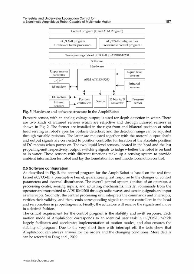
Fig. 5. Hardware and software structure in the AmphiRobot
Pressure sensor, with an analog voltage output, is used for depth detection in water. There are two kinds of infrared sensors which are reflective and through infrared sensors as shown in Fig. 2. The former are installed in the right front and bilateral position of robot head serving as robot’s eyes for obstacle detection, and the detection range can be adjusted through variable resistors. The latter are mounted together with the motors’ output shafts and output signals are connected to position controller for location of the absolute position of DC motors when power on. The two liquid level sensors, located in the head and the last propelling-unit respectively, output switching signals to judge whether the robot is on land or in water. These sensors with different functions make up a sensing system to provide ambient information for robot and lay the foundation for multimode locomotion control.
2.5 Software configuration As described in Fig. 5, the control program for the AmphiRobot is based on the real-time kernel uC/OS-II, a preemptive kernel, guaranteeing fast response to the changes of control parameters and external disturbance. The overall control system consists of an operator, a processing centre, sensing inputs, and actuating mechanisms. Firstly, commands from the operator are transmitted to AT91RM9200 through radio waves and sensing signals are input as interrupts. Secondly, the central processing unit interprets the commands and interrupts, verifies their validity, and then sends corresponding signals to motor controllers in the head and servomotors in propelling-units. Finally, the actuators will receive the signals and move in a desired fashion. The critical requirement for the control program is the stability and swift response. Each
motion mode of AmphiRobot corresponds to an identical user task in uC/OS-II, which
largely facilitates and accelerates implementation of motion modes, and also ensures the
stability of program. Due to the very short time with interrupt off, the tests show that
AmphiRobot can always answer for the orders and the changing conditions. More details
can be referred to Ding et al., 2009.
www.intechopen.com

Motion Control
188
Fig. 6. Developed robotic prototype: AmphiRobot-I and AmphiRobot-II
2.6 Experimental setup Base on the above hardware and software design, as shown in Fig. 6, two robotic prototypes have been successfully fabricated in our laboratory. The dimensions for these two prototypes are about 640mm × 190mm × 110mm and 700mm × 320mm × 150mm, respectively. At present, two control modes have been applied to the amphibious prototype: the manual mode and the automatic control mode. For the former, a custom-built remote controller has been developed. Since radio frequency (RF) waves are severely attenuated under water, once the depth underwater exceeds 300 mm, the RF link will become unreliable and even unconnected. A relatively autonomous mode with the aid of onboard sensors, therefore, is further employed to obstacle-avoidance, diving and surface, aquatic-terrestrial transition, etc. In actual test, the prototype can easily implement the switch between fish-swimming mode and dolphin-swimming mode by regulating the swiveling body mechanism, and can also perform efficient propulsion in each mode. Detailed control methods to terrestrial and underwater locomotion will be elaborated in Sections 3 and 4, respectively.
3. Terrestrial locomotion control
Fig. 7. Two cases for formation of instantaneous center of rotation (ICR) in two locomotion modes on land. (a) The differential drive case. (b) The ackerman steering case.
As a rule, the mobile robot locomotion on land involves differential drive, steered wheel drive, synchronous drive, omni-directional drive and ackerman steering. For the AmphiRobot equipped with wheel-paddles (AmphiRobot-I) or wheel-propeller-fin mechanism (AmphiRobot-II), wheeled locomotion is the basic mode on land. It seems that
www.intechopen.com

Terrestrial and Underwater Locomotion Control for a Biomimetic Amphibious Robot Capable of Multimode Motion
189
the differential drive in Fig. 7a is a reasonable locomotion form. But the slender body of the robot and the lateral friction from rear passive wheels have somewhat negative influence on steering. The poor actual steering performance verifies the incongruity of differential steering. Through careful analysis on the basic configuration, the drive of the AmphiRobot is more similar to that of car drive shown in Fig. 7b. The perpendiculars of two mutually independent wheels and the fixed wheels of a car form an instantaneous center of rotation (ICR) and the orientation of the car will be altered. When the robot body remains straight, the fore driving wheel-like part and rear passive wheels are parallel, no ICR is formed, and the robot moves forward. Benefiting moderately from the carangiform swimming mode in water, the robot’s body shape can be varied when the modular propelling units departure from their central positions, and then the perpendiculars of wheel-paddles and passive wheels intersect and an ICR is formed which makes the robot maneuver on land. Such a maneuvering procedure is hereinafter referred to as “body-deformation steering.” For our robot with three fish-like propelling units, the rotations of the second or third unit independently and the coordinated oscillations of the two units will make the body shape change and meet the requirements of forming an ICR. So there exist three ways available to steer the robot agilely on land. These three methods form different ICRs corresponding to different turning radii, and the following parts will deal with geometry-based analyses and optimization.
3.1 Coordinated deflection via the last two propelling units
Fig. 8. Illustration of changing the body shape via the coordinated deflections of the second and third propelling units, wherein the perpendiculars of wheel-like part and passive wheels form an ICR
www.intechopen.com

Motion Control
190
As shown in the Fig. 8, both the second unit and the third one departure from their middle positions with offset of ┙ and ┚, respectively. The body shape turns from a straight line into an approximate arc shape so that an ICR is coming into being. Once the deflection angles of propelling units are given, D1 and D2 can be calculated according to the below relation of side length and interior angle of triangle:
( )1
sin sin
D D
β π α β= − − ( )2
sin sin
D D
α π α β= − − (1)
where D is a constant. The two right triangles share the same hypotenuse, having
1sin( )
1 22 sin( ) sin
sin
LL LL
L
L
α β γα β γ γγ
⎧⎪⎪⎨⎪⎪⎩
+ − = ⇒ =+ −= (2)
where L1 = D1 + D3, L2 = D2 + D4, specially D3 and D4 are known variables. Combing (1) and (2), ┛ can be solved, and then the turning radius associated with the specific deflection can be derived through R = L1 × cot(┙ + ┚ – ┛):
( )( ) ( ) ( ) ( )
( )2
sin sin cos 3 sin cos 4 sin
sin
D D DR
α β α β α β α β α βα β
+ ∗ + + ∗ + ∗ + + ∗ += + (3)
3.2 Deflection of the second or third propelling unit separately
(a) Separate rotating of the second unit (b) Separate rotating of the third unit
Fig. 9. Illustration of deflecting the second or third propelling unit separately to change the body shape and form new ICRs
As illustrated in Fig. 9, the separate rotating of the second or third unit will also form ICR. According to the above calculation method, the following relationship can be yielded:
αα
∗ + +′ = 3 cos 4
sin
D D DR
( ) ββ
+ +′′ = 3 cos 4
sin
D D DR (4)
www.intechopen.com

Terrestrial and Underwater Locomotion Control for a Biomimetic Amphibious Robot Capable of Multimode Motion
191
3.3 Comparison of three methods
Fig. 10. Comparative result for three methods to form ICR
To further acquire the optimal turning mode, the radii of three turning cases with the same deflection angels are analytically compared. That is, the following relation holds:
α β α β′ ′+ = = (5)
Fig. 10 indicates the comparative result, where the hood facet is the turning radius related to coordinated deflection of the second and third units. The red and black curves denote the turning radii corresponding to the independent deflection of the second and third units. As can be seen, the following inequality is satisfied:
′′ ′< <R R R (6)
With the equal deflections, the case employing the third propelling unit to rotate around its spin axis generates the minimal radius, in which the robot is more maneuverable on land. Furthermore, the individual rotating of the third unit brings about less deviation of passive wheels from the longitudinal centerline, which is beneficial to the stability of the robot.
3.4 Differential velocity Suppose that the revolutions, angular velocities and linear velocities of the left and right wheel-like part are nL, nR, ωL, , ωR and VL,, VR, respectively, the angular velocity of the robot is ω. As can be observed in Fig. 8, the left and right wheel-paddles hold the same angular velocity, i.e.,
πω ωπω ω
⎧ ⎛ ⎞′′= = = ∗ +⎜ ⎟⎪⎪ ⎝ ⎠⎨ ⎛ ⎞⎪ ′′= = = ∗ −⎜ ⎟⎪ ⎝ ⎠⎩
2
60 2
2
60 2
RR R
LL L
n dV r r R
n dV r r R
(7)
where r is the radius of wheel-like part and d is the distance between the two wheel-like parts. Another equation expressed in the revolutions can be further written as
www.intechopen.com

Motion Control
192
′′ += ′′ −
2
2
R
L
dR
n
dn R. (8)
3.5 Kinematic models Base on the optimal body-deformation steering by the deflection of the third propelling unit, the two robot frames are established in the midpoints of the rear wheels and forward wheel-like part, taking the heading of the third propelling unit and head module as the orientations of X axis, and the orientations from right wheel to left wheel as that of Y axis, as shown in Fig. 11.
Fig. 11. Schematic of kinematic model based on the body-deformation steering
For the convenience of theoretical analysis, some suppositions are made below:
• Robot moving on a horizontal plane;
• Point contact of the wheels with ground which are not deformable;
• Pure rolling and no slipping, skidding or sliding;
• Steering axis orthogonal to the surface. It can be easily obtain the following equation:
( )( )θ βθ β
⎧ = +⎪⎨ = +⎪⎩$$
cos
sin
x v
y v (9)
where v is the motion speed of the midpoint of driving wheel-like part; θ is the direction
angle, i.e. the angle between Xm and XW; ┚ is the steering angle of guide wheels; $x and $y are
the translational velocities of Omf.
www.intechopen.com

Terrestrial and Underwater Locomotion Control for a Biomimetic Amphibious Robot Capable of Multimode Motion
193
Via rotating of the third unit causes deviation of passive wheels from the longitudinal central line, and the offset in such a situation is very little compared with the distance between fore and rear wheels. The following equation can therefore be approximated as:
( )θ β=$ / tanv L (10)
where L is the distance between the two midpoints, and θ$ is the rotary velocity.
The equations (10) and (11) compose one of the kinematic models of the robot. Notice that wheel can not move in the direction perpendicular to the wheel plane. To be specific, Omf can not translate along the Ymf axis for the fore wheel and Om can not move along Ym axis. So the following non-holonomic constraint for the amphibious robot holds:
( ) ( )θ θ θ βθ β θ β
⎧ − + =⎪⎨ + − + =⎪⎩$$ $
$ $sin cos cos 0
sin cos 0
x y L
x y (11)
Due to the special steering method, the rear wheels have different radius with that of fore wheel, another kinematic model can be described below:
( ) ( )( ) ( )( )
θ β β θ βθ β β θ β
θ β
⎧ ′ = + + +⎪ ′ = + + +⎨⎪ =⎩
$$$
cos tan sin
sin tan cos
/ tan
x v v
y v v
v L
(12)
where ′$x and ′$y are the translational velocities of Om in the world frame.
Fig. 12. The simulation result of two kinematic models
Based on the kinematic equations (9), (10) and (12), the locomotion trajectories of the robot
can be simulated. As shown in Fig. 12, the circle in blue asterisk is the trajectory of fore
wheel, and the red one is that of rear passive wheels. The error between these two
trajectories is largely caused by the approximation of (10), which is the departure of
midpoint of rear wheels from the longitudinal centerline.
www.intechopen.com

Motion Control
194
Additionally, combining (7) and (10), the relationship between the steering angle and the turning radius can further be derived:
( )β
β+ + ∗=# 3 4 cos
tan
D D DR (13)
Notice that this is only an approximate result, corresponding to the accuracy radius ′′R in (4). A comparative result for this relation is plotted in Fig. 13, where the blue curve denotes the turning radius calculated through the geometric analysis, while the red one is based on the kinematics model. Though the error increases with rising steering angle, the absolute error is relatively small as opposed to the turning radius, which is acceptable in practice. When the steering angle is about 45°, the turning radius approaches a body length of the robot. Notice also that a body length means the length between the fore wheel-like part and rear wheels as the body maintains straight.
Fig. 13. The comparison of turning radii
Fig. 14. Image sequence (anticlockwise) of performing circular motion via the body-deformation steering
www.intechopen.com

Terrestrial and Underwater Locomotion Control for a Biomimetic Amphibious Robot Capable of Multimode Motion
195
3.6 Experimental results To verify the body-deformation steering method and the analysis about the turning radius, experiments have been carried out on the ceramic tile-paved floor in our lab. During testing, the head and the first two propelling units keep in a straight line, the third unit is rotated by a specific angle of 37° which remains the same all the while, with the velocities of the left and right wheel-paddles according with the relationship in (8), and a circular motion is executed, as shown in Fig. 14. Note that the blue and red lines in two snapshots stand for the same locations in the actual ground. The measured steering radius is about 550 mm, and the calculated radii from (4) and (13) are 552 mm and 506 mm, respectively. The negligible error between the theoretical and experimental performance demonstrates the validity of the utilized body-deformation steering approach.
4. Underwater locomotion control
Neurobiology studies have shown that the locomotion of animals is governed hierarchically by the central nervous system, from the cerebral cortex level, the brainstem level, to the spinal cord level (Delcomyn, 1980). Fundamental rhythmic movements in locomotion, such as swimming, walking, running, and flying, are produced by central pattern generators (CPGs) at the spinal cord level. A CPG is a neuronal circuit capable of producing rhythmic patterns of neural activity automatically and unconsciously. The rhythmic pattern activates motor neurons that control the muscles generating the rhythmic movements. At the higher level, CPGs are networks of neurons that can produce coordinated oscillatory signals without oscillatory inputs. The sensory input or descending input from higher elements can regulate the frequency and phase of the rhythmic patterns by altering the intrinsic properties of the neurons and the synaptic strengths and connectivity among them (Delcomyn, 1980; Ijspeert, 2008).
Fig. 15. The simplified CPG model for the AmphiRobot
Typically, there are two kinds of CPG models: chain structure and network structure. The former is commonly used by multi-limbs animals, especially higher vertebrates, e.g. cat, dog, etc. The latter is usually found in aquatic animals such as lamprey and salamander. In the chain CPG, the oscillators are arranged as a line and rhythmic signal is transmitted from one side to another with phases imposed to oscillators. Since the basic locomotion mode of the AmphiRobot in water is carangiform swimming, a bio-inspired controller, i.e. CPG-based control model is employed to generate steady fish-like swimming. From the perspective of biology, fish, as a vertebrate, possesses the similar neural structure similar to
www.intechopen.com

Motion Control
196
chain-like CPG. One motion freedom generally corresponds to an oscillating unit and several oscillating units constitute different and complete topology of CPGs. Therefore, the general structure of the AmphiRobot is functionally depicted in Fig. 15, including pectoral CPG and tail CPG. The oscillating units have the identical structure which comprises two nonlinear oscillators denoting the extensor and flexor, separately.
4.1 Model of nonlinear oscillator For steady anguilliform and carangiform swimming, a propulsive wave form (hereafter referred to as body wave) that results from the progression of muscular contraction from head to tail is exhibited (Barrett, 1996). The replication of traveling body wave allows the robot to propel itself forward in water. This body wave is usually fitted by a sinusoidal function in bio-inspired engineering. Similar to lamprey model, the nonlinear oscillator is described as a phase oscillator with controlled amplitude (Ijspeert et al, 2007):
( )( )
θ π θ θ φττ
⎧ = + − −⎪⎪⎨ ⎧ ⎫⎪ = − −⎨ ⎬⎪ ⎩ ⎭⎩
∑$
$$ $
2 sin
4
i i j ij j i ijj
ii i i i i
f a w
a A a a
(14)
where θi and ai denote state variables representing the phase and the amplitude of oscillator, fi and Ai indicate the intrinsic frequency and amplitude, and τi is a positive constant determining the convergence speed from ai to Ai. The couplings between oscillators are defined by the weight wij and phase biases φij .
The output xi is a positive oscillatory signal expressed by (15) and it is the actual controlling parameters of the AmphiRobot.
( ){ }θ= +1 cosi i ix a (15)
To analyze the converging character of amplitude, the second equation in (14) can be rewritten as
τ ττ+ + =$$ $
2 2
4 4a a a A (16)
So the general solution of preceding equation can be derived below:
( ) τ−= + ⋅ +21 2
t
a C C t e A (17)
Because t is a positive constant, a will approach A when →∞t . That is, the state variable a will ultimately converge to A. The convergence speed is determined by τ. The bigger τ is, the faster the convergence will be.
4.2 CPG network model Two intrinsic cellular reaction mechanisms influence the formation of CPG. One is the rhythmic excitation of single pacemaker cell and another is the synaptic connection between components of neural network. The rhythmic excitation of pacemaker is generated by the oscillation of membrane potential which is driven by several ionic mechanisms. However,
www.intechopen.com

Terrestrial and Underwater Locomotion Control for a Biomimetic Amphibious Robot Capable of Multimode Motion
197
the implementation of membrane oscillation is difficult in engineering practice. In our method, the external stimulus is utilized to excite the oscillation of nonlinear oscillators. The rhythmic excitation supplied by pacemaker cell appears at different occasions in different neurons. Between the two identical pacemaker cells which activate extensor and flexor respectively, there exists the synaptic inhibition. Namely, when a pacemaker cell is active, another does not fire. The synaptic inhibition guarantees the interactive activity of CPG. Oscillating condition and network mechanism including weight and phase are generally involved in CPG model. The network mechanism in the AmphiRobot includes the intrinsic connections of pectoral CPG and tail CPG and mutual connections between them. The network model of AmphiRobot is schematically shown in Fig. 16. The input is the drive which is divided into left part and right one, driving the left and right side of robot body respectively. The pitch arcs represent the connections between oscillators and the arrows are the connection directions. In particular, the oscillating units in the tail CPG possess the same structure and their coordinated oscillations generate thrust for efficient and flexible swimming. We remark that the couplings between different units may be downwards, upwards and contralateral connections. Specifically, the couplings between the tail CPG and the pectoral CPG are defined as the unidirectional connections from oscillators of tail to those of pectoral fins. Some activation limitation is further imposed on the unidirectional couplings, which will be addressed later.
(a) The network with coupling (b) The input drive
Fig. 16. The CPG network for the AmphiRobot
4.3 The design of saturation function To bridge the input drive and oscillators, a special saturation function is imported, which has a direct impact on the output of CPG. Considering the motion mechanism of biological opponent and the energy saving during slow swimming, the AmphiRobot adopts the oscillating length-based control strategy. Each joint is assigned a different threshold which is ascending upwards except that pectoral fins have the same threshold as Joint 4 (J4), as shown in Fig. 16. When the input is below the minimum threshold dlow (the same as dlow,4), all the oscillators can not oscillate and the robot remains still. Once the input is large than dlow,4, the O4, O8 and O9, O10 starts to oscillate, leading to the swing of J4 and pectoral fins, where the AmphiRobot is in the slow-swimming mode. As the input keeps increasing, the J3–J1
www.intechopen.com

Motion Control
198
will participate in the propulsion. At the same time, oscillating frequency and amplitude are in proportion to the input drive and keep increasing. When the input drive reaches the maximum threshold dhigh, the frequency and amplitude achieve the maximum values, respectively, and the robot therefore obtains the maximum velocity. Once the input is larger than dhigh, dhigh will be adopted as the input:
if dleft,right ≥ dhigh dleft,right = dhigh
The amplitude of oscillator has the same functional form in (18). Oscillators in each unit have the same coefficients while different parameters in different units.
+ ≥⎧= ⎨⎩
if
otherwiseA A low
sat
k d b d dA
A (18)
The frequency of oscillator has different saturation function for the tail CPG and the pectoral
CPG. When the left and right input drives are different, the left and right oscillators will
oscillate with distinct frequency and output waves possess the variant periods, the
subtraction of which generates a new wave with modified period. Although the non-
synchronous frequency is feasible in engineering, the coupling of excitation-inhibit on left
and right side will be broken. All the oscillators of the tail CPG are consequently allocated
the same frequency:
( )( ) ( ) ( )
+⎧ + ≥⎪⎪= ⋅ + ≥ ≥⎨⎪⎪⎩
, ,
, ,
if min ,2
max , if max , min ,
otherwise
L Rf tail f tail L R low
tail f tail L R f tail L R low L R
sat
d dk b d d d
f k d d b d d d d d
f
(19)
When the input drive satisfies the oscillating conditions, oscillators will work. In such a case,
the drive is called “effective drive” expressed as deffect. On the other hand, the motion of
pectoral fins does not possess the symmetry and each pectoral fin can work independently.
Thus, the pectoral fins have the same functional form with different parameters:
( ), , if min ,
otherwise
f pec f pec L R low
pec
sat
k d b d d df
f
⎧ + ≥⎪= ⎨⎪⎩ (20)
4.4 Parametric configuration At present, the trial-and-error method based on the simulating techniques of computer is
employed to obtain the characteristic parameters associated with the built CPG model.
Tables 1 and 2 summarize the related parameters for saturation function and for couplings
between oscillators to achieve steady swimming in water. For simplicity, the phase lag
between the left and right pectoral fins is defined as 0. The phase lag between oscillators in
the same unit of tail CPG is defined as π according to the flexor-extensor structure. Since
the traveling wave propagates from head to tail, the downward phase lag is defined as π /4, accordingly the upward phase as π− /4. The pectoral fins and J4 oscillate in phase
and thereby the phase relationship between pectoral and tail oscillators can be derived.
www.intechopen.com

Terrestrial and Underwater Locomotion Control for a Biomimetic Amphibious Robot Capable of Multimode Motion
199
Variables Symbol The tail CPG The pectoral CPG
Number of oscillators N 8 2
Time constant τ 20
Minimum threshold dlow [2.5, 2, 1.5, 1] (J1–J4) 1
Maximum threshold dhigh 5
Frequency coefficient [kf, bf] [0.45, 0.3] [0.5, 0.3]
Amplitude coefficient [kA, bA]
[0.030, 0.10] (J1) [0.035, 0.12] (J2) [0.045, 0.14] (J3) [0.055, 0.16] (J4)
[0.08, 0.06]
Saturation frequency fsat 0
Saturation amplitude Asat 0
Table 1. The parameters in saturation function
Variables Symbol The tail CPG The pectoral CPG
Coupling (in the tail CPG)
(downwards) [wij, φ ij]
(upwards) [wij, φ ij]
(contralateral) [wij, φ ij]
[10, π /4]
[10, –π /4]
[10,π ]
Coupling (the tail CPG to the
pectoral CPG)
[w19, φ 19]
[w29, φ 29]
[w39, φ 39]
[w49, φ 49]
[w5, 10, φ 5, 10]
[w6, 10, φ 6, 10]
[w7, 10, φ 7, 10]
[w8, 10, φ 8, 10]
[0/30, 3π /4]
[0/30, 2π /4]
[0/30,π /4]
[0/30,0] [0/30,–π /4]
[0/30, –2π /4]
[0/30, –3π /4]
[0/30, –π ]
Coupling (in the pectoral CPG)
[10, 0]
Table 2. The parameters for couplings between oscillators
Notice that two kinds of weight from the tail CPG to the pectoral CPG are pre-set. When the robot moves slowly, the weight is 0. While in fast swimming, the weight is chosen as 30. The critical condition for weight switch is triggered by the value of effective drive. The weight is 0 when 3effectd < and 30 when 3effectd ≥ .
4.5 On-line generation of control parameters In the conventional body wave-based control method, the oscillating positions in a period is fixed. The speed control mainly depends on the time delay between two positions (Yu et al., 2004). The less the delay is, the faster the robot swims. The robot obtains the maximum speed in case of the minimum time delay. Due to the fixed but limited control points, the fish-like oscillations is relatively stiff. In addition, the robot is unable to adjust the characteristics according to the external environment and internal state. Considering these factors, CPG-based model is integrated to produce control parameters in real time.
www.intechopen.com

Motion Control
200
In practice, the subtraction of output of two oscillators in one tail unit is used to actuate the corresponding servomotor, as shown in (21), whereas the outputs of pectoral oscillators are directly adopted as control signal.
4i i ix xϕ += − (21)
where i=1, 2, 3, 4. An example of the input drive for straight swimming is plotted in Fig. 17, and corresponding output signal for oscillating units in Fig. 18.
Fig. 17. The activity of CPG in straight swimming
Fig. 18. The applied control signals in straight swimming
Further, assuming i ia y=$ and i iy a=$ $$ , a set of reduced-order equation is employed to yield
control data:
www.intechopen.com

Terrestrial and Underwater Locomotion Control for a Biomimetic Amphibious Robot Capable of Multimode Motion
201
( )( )
2 sin
4
i i j ij j i ijj
i i
ii i i i i
f a w
a y
y A a y
θ π θ θ φ
ττ
⎧ = + − −⎪⎪⎪ =⎨⎪ ⎛ ⎞⎪ = − −⎜ ⎟⎪ ⎝ ⎠⎩
∑$
$
$
(22)
The 10 oscillators of the CPG network are made up of 30 reduced-order equations, which means considerable computing burden and an efficient numerical method is obligatory. With the processing frequency of 180 MHz in the ARM AT91RM9200 microcontroller, the 4-order and three-order Runge-Kutta in tests consumed about 43 ms and 33 ms, respectively, both of which are higher than 20 ms, the intrinsic control period of servomotors. To mitigate the computation consumption, a simplified Euler method is utilized to solving the equation (22). The iterative method of Euler is outlined as below:
( )1 ,n n n ny y hf x y+ = + (23)
The computing amount of the Euler method is only a quarter of that of four-order Runge-Kutta. The time consumption is reduced to about 13–14 ms, which satisfies the requirement of real-time computation.
4.6 Experimental results During testing, different drives with bilateral symmetry and varied strength are applied to the AmphiRobot. All the joints from J1 to J4 are involved in the propulsion sequentially. A comparison of actual swimming wave and the simulating wave are depicted in Fig. 19. Notice that the snapshots of swimming are clipped from the experimental video and the straight lines in the simulating results denote joint J1–J4. In Fig. 19a, pectoral fins and joint J4 initially started to oscillate simultaneously when the input drive reached the threshold of these oscillators, and others joints remained still in their middle positions. By analogy, the oscillators corresponding to the J3–J1 from Figs. 19b–d participated in the driving, and the oscillating frequency and amplitude increased in proportion to the input drive. In the comparisons, the actual moving pattern agrees with simulation result, which verifies the feasibility of the CPG network. Note also that an irregular jerk emerged while powered on and it was caused by the fact that random numbers were assigned to the initial values of (22). This jerk disappeared quickly when the random initial values converged to the regular oscillating wave. The jerk demonstrates a potential advantage of CPG model that the controller can switch to stable locomotion from an arbitrary state and eliminate disturbance effectively. Furthermore, the relationship between speed and symmetrical input drives in straight swimming is summarized in Fig. 20. When the inputs exceeded the minimum threshold, the AmphiRobot began to swim. Because only pectoral fins and J4 were involved in propulsion, the swimming speed was very low. The profile of moving velocity was similar with an exponential curve and the acceleration increased constantly when the drives ranged from dlow,4 to dlow,1. Though the swimming speed continued to augment when the inputs were above dlow,1, the acceleration decreased remarkably. The swimming attained the maximum speed when inputs reached maximum acceptable drives. The whole profile was clearly divided into two distinct phases by the point dlow,1. In the first stage, besides the speed
www.intechopen.com

Motion Control
202
increased with increasing frequency and amplitude, the active body length involved in the swimming increased continually because of the participation of more joints. Nevertheless, all the joints functioned and the active body length remained invariant in the second stage. The two-phase profile demonstrated that the oscillating body length plays an important role in the swimming speed of the AmphiRobot.
(a) drive=1
(b) drive=1.5
www.intechopen.com

Terrestrial and Underwater Locomotion Control for a Biomimetic Amphibious Robot Capable of Multimode Motion
203
(c) drive=2
(d) drive=2.5
Fig. 19. A comparison of actual swimming and simulation results
www.intechopen.com

Motion Control
204
Fig. 20. The relationship of swimming speed and drive difference
5. Conclusion
This chapter has reviewed some of the issues involved in creating a multimode amphibious robot, especially its mechanical design and motion control, in a biomimetic manner. Based on the body structure, motion characteristics of amphibians, two generations of multimode biomimetic amphibious robots, named “AmphiRobot”, have been developed. For terrestrial movements, a geometry based steering method called body-deformation steering has been proposed and optimized, taking advantage of the wheel-like mechanisms attached to the robot. At the same time, a chainlike CPG network responsible for coordinated swimming between multi-joint tail and artificial pectoral fins has been built. The aquatic control parameters mainly involve the length of undulation part, oscillating frequency and amplitude cooperatively regulated by the threshold values of the saturation function for each propelling unit. The real-time online calculation of controlling parameters has been also implemented. Preliminary testing results, both on land and in water, have demonstrated the effectiveness of the proposed control scheme. However, the amphibious locomotion performance of the AmphiRobot is still far behind that of animals in terms of speed and agility, especially in complex unstructured environments. More cooperative efforts from materials, actuators, sensors, control as well as learning aspects will be needed to improve the robot locomotor skills in unstructured and even unknown surroundings. The ongoing and future work will focus on the analysis and optimization of locomotion control for autonomous movements as well as flexible water-land transitions. Hydrodynamic experiments based hybrid mechanical/electrical optimization, of course, is a plus for real-world applications.
6. Acknowledgement
The authors would like to thank Prof. Weibing Wang in the Machine and Electricity Engineering College, Shihezi University, for his contribution to mechanical design and fabrication of the AmphiRobot.
www.intechopen.com

Terrestrial and Underwater Locomotion Control for a Biomimetic Amphibious Robot Capable of Multimode Motion
205
This work was supported in part by the National Natural Science Foundation of China under Grants 60775053 and 60505015, in part by the Municipal Natural Science Foundation of Beijing under Grant 4082031, in part by the National 863 Program under Grant 2007AA04Z202, and in part by the Beijing Nova Programme (2006A80).
7. References
Ayers, J. (2004). Underwater walking, Arthropod Structure and Development, Vol. 33, pp. 347–360
Bandyopadhyay, P.R. (2004). Guest editorial: biology-inspired science and technology for autonomous underwater vehicles, IEEE J. Ocean. Eng., Vol. 29, No. 3, pp. 542–546
Bandyopadhyay, P.R. (2005). Trends in biorobotic autonomous undersea vehicles, IEEE J. Ocean. Eng., Vol. 30, No. 1, pp. 109–139
Barrett, D.S. (1996). Propulsive efficiency of a flexible hull underwater vehicle, Dissertation for the Doctoral Degree, Cambridge, MA: Massachusetts Institute of Technology
Boxerbaum, A.; Werk, P.; Quinn, R. & Vaidyanathan, R. (2005). Design of an autonomous amphibious robot for surf zone operation: Part I mechanical design for multi-mode mobility, Proc. of the 2005 IEEE/ASME International Conference on Advanced Intelligent Mechatronics, pp. 1460–1464
Delcomyn, F. (1980). Neural basis for rhythmic behaviour in animals, Science, Vol. 210, pp. 492–498
Ding, R.; Yu, J.; Yang, Q.; Hu, X. & Tan, M. (2009). Platform-level design for a biomimetic amphibious robot, Proc. of IEEE International Conference on Robotics and Biomimetics, Bangkok, Thailand, pp. 977–982
Fish, F.E. & Rohr, J.J. (1999). Review of dolphin hydrodynamics and swimming performance, Technical Report 1801, SPAWARS System Center San Diego, CA
Georgiades, C.; Nahon, M. & Buehler, M. (2009). Simulation of an underwater hexapod robot, Ocean Engineering, Vol. 36, pp. 39–47
Greiner, H.; Shectman, A.; Won, C.; Elsley, D. & Beith, P. (1996). Autonomous legged underwater vehicles for near land warfare, Proc. Symp. Autonom. Underwater Vehicle Tech., pp. 41–48
Harkins, R.; Ward, J.; Vaidyanathan, R.; Boxerbaum, A. & Quinn, R. (2005). Design of an autonomous amphibious robot for surf zone operation: Part II - hardware, control implementation and simulation, Proc. of the 2005 IEEE/ASME International Conference on Advanced Intelligent Mechatronics, pp. 1465–1470
Healy, P.D. & Bishop, B.E. (2009). Sea-dragon: an amphibious robot for operation in the littorals, Proc. of 41st Southeastern Symp. on System Theory, University of tennessee Space Institute, Tullahome, TN, USA, pp. 266–270
Ijspeert, A.J.; Crespi, A. & Cabelguen, J.-M. (2005). Simulation and robotic studies of salamander locomotion: applying neurobiological principles to the control of locomotion in robots, Neuroinformatics, Vol. 3, pp. 171–196
Ijspeert, A.J.; Crespi, A.; Ryczko, D. & Cabelguen, J.-M. (2007). From swimming to walking with a salamander robot driven by a spinal cord model, Science, Vol. 315, No. 5817, pp. 1416–1420
Ijspeert, A.J. (2008). Central pattern generators for locomotion in animals and robots: a review, Neural Networks, Vol. 21, No. 4, pp. 642–653
www.intechopen.com

Motion Control
206
Kemp, M.; Hobson, B. & Long, J. (2005). Madeleine: an agile auv propelled by flexible fins, Proc. of the 14th International Symposium on Unmanned Untethered Submersible Technology (UUST), pp. 1–6
Lauder, G.V.; Anderson, E.J.; Tangorra, T.J. & Madden, P.G.A. (2007a). Fish biorobotics: kinematics and hydrodynamics of self-propulsion, The Journal of Experimental Biology, Vol. 210, pp. 2767–2780
Lauder, G.V. & Madden, P.G.A. (2007b). Fish locomotion: kinematics and hydrodynamics of flexible foil-like fins, Exp. Fluids, Vol. 43, pp. 641–653
Prahacs, C.; Saunders, A.; Smith, M.; McMordie, D. & Buehler, M. (2005). Towards legged amphibious mobile robotics, J. Eng. Design and Innovation (online), vol. 1, part. 01P3, Available: www.cden.ca/JEDI/index.html
Sfakiotakis, M.; Lane, D.M. & Davies, J.B.C. (1999). Review of fish swimming modes for aquatic locomotion, IEEE J. Oceanic Eng., Vol. 24, No. 2, pp. 237–252
Yamada, H.; Chigisaki, S.; Mori, M.; Takita, K.; Ogami, K. & Hirose, S. (2005). Development of amphibious snake-like robot ACM-R5, Proc. of 36th Int. Symposium on Robotics, pp. 433–440
Yang, Q.; Yu, J.; Tan, M. & Wang, S. (2007). Amphibious biomimetic robots: a review, Robot, Vol. 29, No. 6, pp. 601–608
Yu, J.; Tan, M.; Wang, S. & Chen, E. (2004). Development of a biomimetic robotic fish and its control algorithm, IEEE Trans. Syst., Man, Cybern. B, Cybern., Vol. 34, No. 4, pp. 1798–1810
Yu, J.; Hu, Y.; Fan, R.; Wang, L. & Huo, J. (2007). Mechanical design and motion control of a biomimetic robotic dolphin, Advanced Robotics, Vol. 21, No. 3–4, pp. 499–513
Wang, L.; Sun, L.; Chen, D.; Zhang, D. & Meng, Q. (2005). A bionic crab-like robot prototype, Journal of Harbin Engineering University, Vol. 26, No. 5, pp. 591–595
www.intechopen.com

Motion ControlEdited by Federico Casolo
ISBN 978-953-7619-55-8Hard cover, 590 pagesPublisher InTechPublished online 01, January, 2010Published in print edition January, 2010
InTech EuropeUniversity Campus STeP Ri Slavka Krautzeka 83/A 51000 Rijeka, Croatia Phone: +385 (51) 770 447 Fax: +385 (51) 686 166www.intechopen.com
InTech ChinaUnit 405, Office Block, Hotel Equatorial Shanghai No.65, Yan An Road (West), Shanghai, 200040, China
Phone: +86-21-62489820 Fax: +86-21-62489821
The book reveals many different aspects of motion control and a wide multiplicity of approaches to theproblem as well. Despite the number of examples, however, this volume is not meant to be exhaustive: itintends to offer some original insights for all researchers who will hopefully make their experience available fora forthcoming publication on the subject.
How to referenceIn order to correctly reference this scholarly work, feel free to copy and paste the following:
Junzhi Yu, Qinghai Yang, Rui Ding and Min Tan (2010). Terrestrial and Underwater Locomotion Control for aBiomimetic Amphibious Robot Capable of Multimode Motion, Motion Control, Federico Casolo (Ed.), ISBN:978-953-7619-55-8, InTech, Available from: http://www.intechopen.com/books/motion-control/terrestrial-and-underwater-locomotion-control-for-a-biomimetic-amphibious-robot-capable-of-multimode

© 2010 The Author(s). Licensee IntechOpen. This chapter is distributedunder the terms of the Creative Commons Attribution-NonCommercial-ShareAlike-3.0 License, which permits use, distribution and reproduction fornon-commercial purposes, provided the original is properly cited andderivative works building on this content are distributed under the samelicense.