tesla coil design for electron gun application
TRANSCRIPT
TESLA COIL DESIGN FOR ELECTRON GUN APPLICATION
M. Parafiev%, C. Gough, S. IvkovicPaul Scherrer Institute, Accelerator Division
5232 Villigen PSI, Switzerland
Abstract describe our results of optimizing the parameters of theresonant air-core transformer.
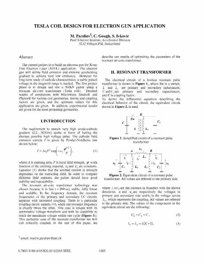
The current project is to build an electron gun for X-rayFree Electron Laser (XFEL) application. The electrongun will utilize field emission and extreme accelerating II. RESONANT TRANSFORMERgradient to achieve very low emittance. However forlong-term study of cathode characteristics, a stable pulsed The electrical circuit of a lossless resonant pulsevoltage in the megavolt range is needed. The first project transformer is shown in Figure 1., where Sw is a switch,phase is to design and test a 500kV pulser using a L and Ls are primary and secondary inductances,resonant air-core transformer (Tesla coil). Detailed C and Cs are primary and secondary capacitances,results of simulations with Microwave Studio® and and K is coupling factor.PSpice® for various coil geometries, tuning and coupling To derive the differential equations describing thefactors are given, and the optimum values for this electrical behavior of the circuit, the equivalent circuitapplication are given. In addition, experimental results shown in Figure 2. is used.are given for the most promising geometries.
K
I.INTRODUCTION c SC,The requirement to sustain very high anode-cathode T L L
gradient (0.2... lGV/m) spoke in favor of having the Ishortest possible high voltage pulse. The cathode field Figure 1. Simplified circuit of a resonant pulseemission current I is given by Fowler-Nordheim law transformershown below:
2 (O3/2) U3 BI=AclF expL- c2Y ()A B
where A is emitting area, F is local field strength, y work u, 34 I iS U2function of the emitting material, cl and c2 are constants. C L1 L2 C2Equation (1) shows that the emitted current is strongly I Idependant on the extracting field. In order to compare Figure 2. Equivalent circuit of a resonant pulsedifferent field emitters, the pulser should have good transformer. All values are referred to the primary side.stability and repeatability.The resonant air-core transformer technology was
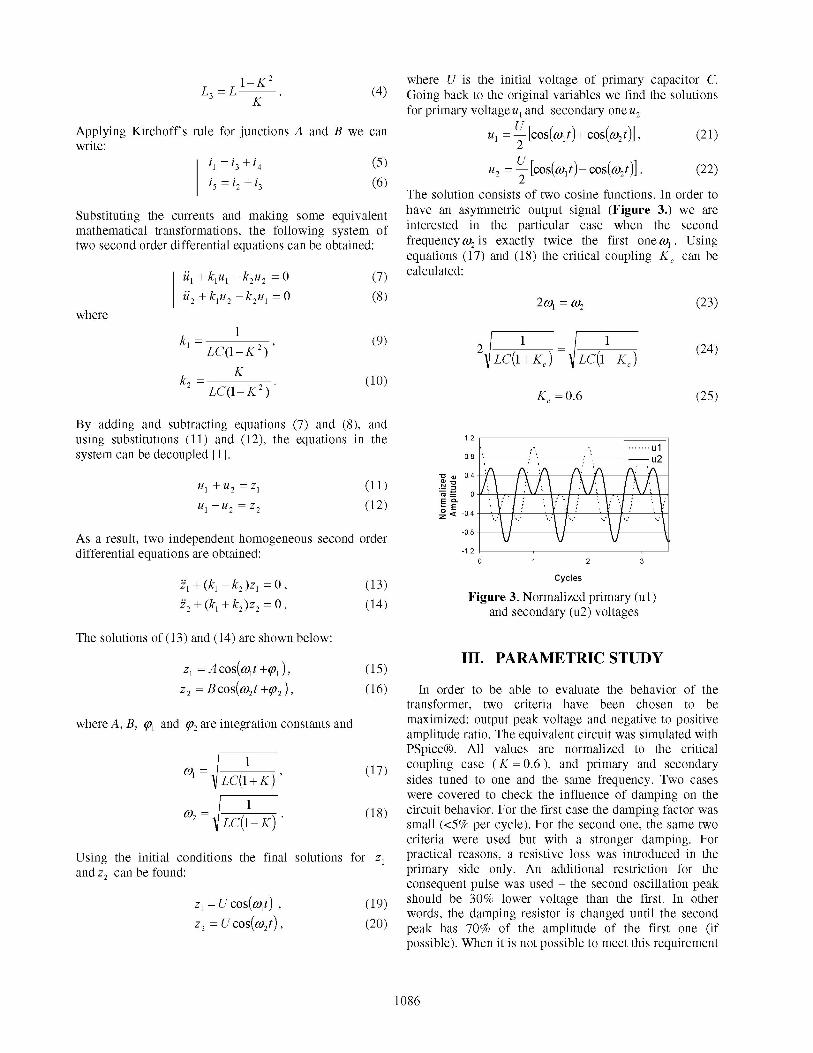
chosen because it is fast (z 200 ns), stable, fully linear where i1 to i5 are the currents in branches with the shownand scalable. In the frequency domain, the resonant directions, ul and u2are respectively the voltages infrequencies of the primary and secondary LC circuits primary and secondary side andU3 is the voltage acrossseparate with increased coupling. There is a particular L3, which represents the coupling. All values are referredcoupling factor, namely 0.6, when one resonant frequency to the primary side. The values of the components in theis exactly twice the other. This case is unique with its equivalent circuit are the following:asymmetric voltage waveform and with its capability toreach the maximum voltage within one cycle (Figure 3.). Cl = C2 = C, (2)This particular case of the resonant transformer we willcall critically coupled. In the rest of this paper, we -= = L(K+1), (3)
4 email: martin.paraliev @psi.ch
0-7803-9189-6/05/$20.00 ©C2005 IEEE. 1085
1-K2 where U is the initial voltage of primary capacitor C.L3= L (4) Going back to the original variables we find the solutions
for primary voltage ul and secondary one u2Applying Kirchoff's rule for junctions A and B we can Ul U-[Colt)+COS(01] (21)write: 2
11 =13 +14 (5) =-[cos(OS(t) - cos(cO2t)]. (22)i5 =2 +i3 (6) 2
The solution consists of two cosine functions. In order to
Substituting the currents and making some equivalent have an asymmetric output signal (Figure 3.) we aremathematical transformations, the following system of interested in the particular case when the secondtwo second order differential equations can be obtained: frequency 02 is exactly twice the first one o . Using
equations (17) and (18) the critical coupling KC can be
l+ k1u - k2u2 = 0 (7) calculated:U2 I 12 212
| 2+ k1u2 -k2ul =0 (8) 2coil =2 (23)where
L= L(I K2)' 2 1K
1 (24)
k2= K (10)LC(1-K2) K =0.6 (25)
By adding and subtracting equations (7) and (8), andusing substitutions (11) and (12), the equations in the 1.2system can be decoupled [1]. 0.8 u2
U+U2 =z1 (1)
81-82=Z2 ~~~(12) °Q 0 ''\ '' '
As a result, two independent homogeneous second order-0 VVdifferential equations are obtained: -.
0 1 2 3
z1 + (k1 -k2)z1 =0,' (13) Cycles
Z2(l +k2z2= 0. (14) Figure 3. Normalized primary (ul)E and secondary (u2) voltages
The solutions of (13) and (14) are shown below:
z12Acos(co1t2y1), (15) III. PARAMETRIC STUDY
Z= Bcos(co2t +y2), (16) In order to be able to evaluate the behavior of thetransformer, two criteria have been chosen to be
where A, B, ql and y2 are integration constants and maximized: output peak voltage and negative to positiveamplitude ratio. The equivalent circuit was simulated withPSpice. All values are normalized to the critical
1 k 1k) (17) coupling case (K =0.6), and primary and secondaryLC(1 sides tuned to one and the same frequency. Two casesI2Bcos( t 02 (16) Inwere covered to check the influence of damping on the
0t)2 =-/ 1 *t(18) circuit behavior. For the first case the damping factor wasLC(1- K) small (<5% per cycle). For the second one, the same two
criteria were used but with a stronger damping. ForUsing the initial conditions the final solutions for z, practical reasons, a resistive loss was introduced in theandOz2 canbefound: primary side only. An additional restriction for the
consequent pulse was used - the second oscillation peakZ= u cos(a)lt) (19) should be 30% lower voltage than the first. In other
1J2 (18) ciwords, the damping resistor is changed until the secondC=U cos(ma2t) (20) peak has 70% of the amplitude of the first one (if
possible). When it is not possible to meet this requirement
1086

the chart goes to zero. Figure 4. represents the peak value IV.COIL GEOMETRYof the output oscillation and Figure 5. shows negative topositive peak voltage ratio, both as function of primary In order to find the optimal transformer layout,capacitance and coupling factor. different transformer geometries and conductor cross
sections were compared. The study was conducted using3D PC based electromagnetic solver (MicrowaveStudio®) results and prototype measurements.
120%- / = j _ Unfortunately the simulations appeared to be very/ xf kfwg g t ...............*~u1-1.2Ef_.081 sensitive to mesh density. One way around this problem is
Normalized |/ 0 to keep exactly the same meshing in all the simulationsAmplitude of 80-independent of studied paaee.The lreratio between
Secondary prmtr agVoltage the dimensions of the modeled coil and conductor cross-
wl l0111r/ 0.70 section details results in a large number of mesh points40%Coupling and respectively long computing time.40%- .50~~~~~~L Factor K
40 % 83 % 143% 0 4 The results for two transformer geometries areNormalized Primary Capacitance presented: helical and spiral. Both types were measured in
autotransformer mode with one turn primary. For theFigure 4. Normalized secondary peak voltage spiral type, central and peripheral excitation was used, asamplitude as function of coupling and primary it is shown in Figure 6.
capacitance with 30% loss factor
Ell B-1 0
160%J _ 1.41.6..Ei1.2-14 Central Excitation Peripheral Excitation
/ X x/s ~ ~ ~ 2-1
Ap/An 140%.-l112
Ratio 14U% *o~~~0.8- Figure 6. Central and Peripheral ExcitationRatio 120% w | ; l > of spiral type transformer
100%- ._ L80%- /X 7
40%_ = °55 Coupling V. SIMULATION AND EXPERIMENTALNormalized Primary 1A0.40 Factor K RESULTS
Capacitance
Figure 5. Negative to positive peak voltage ratio of Microwave Studio® model of 20 turns spiral coil, withsecondary voltage as function of coupling and outer diameter 370mm, span 3.6mm, made out of stripprimary capacitance with 30% loss factor conductor 5mm wide and 0.9mm thick, is shown in
The graphs show that the negative to positive peak Figure 7.voltage ratio is more sensitive to the parameters changethan the peak amplitude. Table 1. summarizes theparametric study results.
Table 1. Summarized results of the parametric studyDamping <5% 30%
Absolute max. norm. voltage, % 120 115Conditions: Figure 7. Microwave Studio® model
- Coupling 0.60 0.60- Norm. capacitor, % 207 250 0.90
0.85---Masreen
Acceptable change of + +7 0.80I ~~~~~~~~~~+4+7 0.80 A Simulationcoupling factor1), % 2 -20.0.75
Acceptable change of norm. +34 +40 0 0.70capacitance 1), % -34 -17 0.60
1)With respect to absolute max. voltage point. Conditions: amplitude Turns1 2 2change -20%, negative to positive ratio ±10%.Tun
Figure 8. Simulation vs. measurement
1087

Graphic representation of the results based on Microwave To evaluate the influence of the conductor size on theStudio® simulations and prototype measurements are coupling, two strips with different width were chosen.shown in Figure 8. The results for helix and spiral transformers are shown in
Three parameters that affect the coupling were studied: Figure 12.transformer geometry, conductor cross-section profile andconductor size. A set of transformer prototypes with 1.00different geometries was built and measured (Figure 9.). 0.80
. 0.60
. 0.40 Spiral Strip 50x10 -e--- Spiral Strip 14x1
||0.20 -h.- Helix Strip 50x1
0.000 2 4 6 8 10 12 14
Turns
Figure 12. Air-transformer conductorsize comparison.
VI.CONCLUSIONS
Figure 9. Measured prototypes The performed parametric study showed that the
Three transformer types were compared - helix, spiral output pulse amplitude and shape are sensitive to thecoupling and relatively less sensitive to primarywith central excitation and spiral with peripheral copling an rel ativelylspesitivet piarcapacitance. To keep large negative to positive peak
excitation. To make a fair comparison the diameter of the voltage ratio of the output pulse, the coupling factorhelix was equal to the mean spiral diameter and all the should be kept within 0.58 to 0.62. Slightly larger value ofother parameters were kept the same. The results are primary capacitance (with respect to the tuned value)shown in Figure 10. gives an improvement in amplitude without changing the
1.00 negative to positive ratio too much.With increasing number of turns the coupling
0.80 decreases. The spiral transformer with peripheral.S 0.60 excitation gives the best coupling for given dimensionsa I Iand conductors span. The influence of the conductorO0 0.40 -t-Spiral Peripheral|j....o 0.0 piralHelix pl cross-section profile on coupling is small on condition
0.20 -- SpiralCentral that the conductor cross-section perimeter is the same. In0.00 general wider strips give better coupling.
0 2 4 6 8 10 12 14 The difference in coupling between simulations (withTurns fixed mesh) and measurements is less than 1%.
In general, scaling the size of the transformer gives aFigure 10. Air-transformer geometry comparison, linear scaling of all self and mutual inductances but does
not change the coupling.To evaluate the influence of the conductor cross-section
profile on the coupling, two cases with same perimeterwere chosen - round and strip conductor. The results for VII. REFERENCEShelix and spiral transformers are shown in Figure 11.
1.00 [[1] Frank L. H. Wolfs, Physics Lecture Notes 2004,0.80 University of Rochester, Rochester, NY 14627, USA
0.8.- 0.60
-0--Spiral Round 090.40-O x Spiral Strip 14xl
0.20 -c-- Helix Round 09-H- Helix Strip 14xl
0.000 2 4 6 8 10 12 14
Turns
Figure 11. Air-transformer conductor cross-sectionprofile comparison.
1088